
DOE/EW82763 -2 A GENERIC APPROACH TO …/67531/metadc738475/m2/1/high... · IMPROVED SEMI-SOLID...
31
- i ,? . - . .. DOE/EW82763 -2 A GENERIC APPROACH TO OF METALS IMPROVED SEMI-SOLID FORMING Final Report For Period June 6,2000 - June 5,2002 Eric M. Klier Chesapeake Composites Corporation 239 Old Churchmans Road New Castle, DE 19720 June 2002 Prepared for THE U.S. DEPARTMENT OF ENERGY Under Award Number DE-FG02-99ER82 7 63
Transcript of DOE/EW82763 -2 A GENERIC APPROACH TO …/67531/metadc738475/m2/1/high... · IMPROVED SEMI-SOLID...
- i ,? . - . . .
DOE/EW82763 -2
A GENERIC APPROACH TO
OF METALS IMPROVED SEMI-SOLID FORMING
Final Report
For Period June 6,2000 - June 5,2002
Eric M. Klier
Chesapeake Composites Corporation 239 Old Churchmans Road
New Castle, DE 19720
June 2002
Prepared for
THE U.S. DEPARTMENT OF ENERGY Under Award Number DE-FG02 -9 9ER8 2 7 63

This report was prepared as an acco1uIt of work sponsored by an agency of the United States Government. Neither the United States Government nor any agency thereof, nor any of their cmploytts, makes any warranty, express or impiiod, or assumes any kgal liability or rcsponsibilhy for the accuracy. completeness, or use- fulness of any information, apparatus, product, or proass dwlweb or rcpnsents that its use would not infringe privately owned rigbts. Reference herein to any spe- cific commercial product, proass, or &ce by trade name, trademark, manufac- turer, or otherwise docs not necessarily coastitute or imply itf cndonement, recom- mendktion. or favoring by the United St+s Government or any agency thmof. The views and opinions of authors exprrssed herein do not necessarily state or reflect those of the United States Government or any agency thereof.

DISCLAIMER
. Portions of this document may be illegible in electronic image products. Images are produced from the best available original document.

NOTICE
This report was prepared as an account of work sponsored by the United States Government. Neither the United States nor the United States Department of Energy, nor any of their employees, nor any of their awardees, subcontractors, or their employees, makes any warranty, express or implied, or assumes any legal liability or responsibility for the accuracy, completeness, or usefdness of any information, apparatus, product or process disclosed or represents that its use would not infiinge privately- owned rights.

, : . i
Abstract
Chesapeake has developed a manufacturing approach for scale-up to 6" diameter billets. This approach has been inserted into an extant ceramic manufacturing facility to yielding a plant with the capability of up to 5 million pounds per year of billets up to 6" m diameter. The manufacturing approach is summarized as follows:
0 Aqueous ball milling for the production of a ceramic sluny
Spray drying for the formation of a iiee flowing powder for pressing
Isostatic pressing for the formation of large cylindrical preforms
0 Burnout and firing in air kilns
Liquid metal infiltration using vertical squeeze infiltration press
All process steps utilize commercially available equipment that operates continuously or in large batches. Furthermore, the process steps are highly automated and coordinated for reduced labor costs, inventory costs and to minimize cycle time.
Finally, the results of the 4" diameter billet work and the manufacturing approach were incorporated into Chesapeake's existing cost model to evaluate the primary processing costs at the 4" diameter billet level. Results of the cost model indicate that the cost/Ib. to manufacture DSCTM Aluminum billet is consistent with the market interest (what customers are willing to pay) for the product.
Materials and experimental techniques
Three composite castings and one ceramic preform were evaluated. Two of the castings are very similar in terms of volume hction ceramic while the third has a slightly higher volume fraction. In what follows, these materials will be designated as Clay Clb, and C2, respectively. The ceramic preform corresponds to the C 1 castings and will be designated P 1.
Optical Microscopy (OM) and Scanning Electron Microscopy (SEM) were used to characterize the microstructures of as-cast composites after standard diamond-based metallographic preparation techniques. For SEM imaging, a final electropolishing step was introduced (3sec at 50V with Struers A2 electrolyte) after mechanical polishing in order to remove a layer of Al (which is preferentially electropolished) and reveal the reinforcement architecture within the composite (in the case of compressed samples it also helps to reveal any

voids within the m a h of the composites produced during straining, which would not be discemable after simple mechanical polishing due to smearing of the soft Al matrix). High precision helium pycnometry was employed in determining the density of the as-cast composites. Volume fi-actions of cerarnic in the as-cast materials were determined from these density measurements assuming no porosity and densities for bulk & 0 3 and Al of 3.97 gkm3 and 2.6989 g/cm3, respectively.
Compressive testing was conducted on cylindrical samples 10 mm in diameter and 15 mm m height. It was experimentally determined that this specific sample geometry has the maximum aspect ratio for which no plastic buckling occurs. The samples were compressed between polished WC platens in a 100 kN servohydraulic universal testing machine outfitted with a h a c e and a controlled atmosphere chamber. Teflon was used as a lubricant between the sample and the platen surfaces up to 250 "C, while BN was used at higher temperatures.
For all experiments above room temperature the testing chamber was first evacuated and flushed with argon (to avoid oxidation of the WC platens), then heated at 10 "C/min to the specific testing temperature and left to equilibrate for 45 min prior to testing. The rate of cooling of the c h b e r after testing is the same as the heating rate. The compressive behavior of the composites was determined at 25 "C, 250 "C, 500 "C, 600 "C, 670 "C and 720 "C. Compressive tests were conducted on ceramic preforms prior to infiltration at 25 "C, 600 "C, and 670 "C.
In all compression tests, the machine was piloted under crosshead displacement control. Strain in the samples was determined from this displacement, corrected for the (temperature- dependent) compliance of the testing set-up. Measured stram-rates throughout a single test never vary by more than a factor of 1.3. The strain rate-dependence of the composite flow curves was determined at 25 "C, 250 "C and 670 "C, and for nominal strain rates of 10" s-', 1 O-* s-', lo-' s-', and 10' s-' .
The elastic constants of the as-cast composite samples (same sample geometry as for mechanical testing) were determined using an ultrasonic wave reflection technique. In particular, the speed of sound in the as-cast samples was determined using a 25 MHz transducer linked to a digital oscilloscope.
In an attempt to study the effect of deformation history on the microstructure and the subsequent compressive response of the present composites the following experiments were conducted:
(i) dissolution of the composite matrix in a caustic solution (concentrated NaOH + KOH) a k r different amounts of pre-strain at various testing temperatures
(ii) testing of the composites at 25 "C, 250 "C, and 670 "C after a given amount of pre-strain at 500 "C

. . . .
(iii) testing ofthe composites at quasi-static strain rates (10" s-l) after pre-stmining at higher strain rates (lo-' s" and 10' s-'), and
(iv) determination of changes in the density and elastic constants of the composites as a result of deformation under various testing conditions. All of the above experiments are complemented by metallographic studies of deformed samples.
Microstructure and physical properties
As cast composite microstructures are characterized by a relatively homogeneous distribution of fine ceramic particles in a pore-free matrix, Fig. la. There seems to be a slight structuring of the composite on the intermediate scale; spheres of sintered particles on the order of 100 kmm diameter (in comparison to the particles which are nominally 0.3 l m in diameter), which are surrounded by channels of unreinforced Al matrix, can be seen in the OM of Fig. la, and at a higher magnification in the SEM, Fig. lb. These spheres are probably a product of the freeze- drying step during preform preparation. In Fig. 1 b one can also see that the reinforcing phase in the composites is interconnected which is a direct result of sintering of the ceramic preform prior to infiltration. In fact, the present composites have interpenetrating phase microstructures and are very similar to other interpenetrating phase composites (IPCs) found in literature.
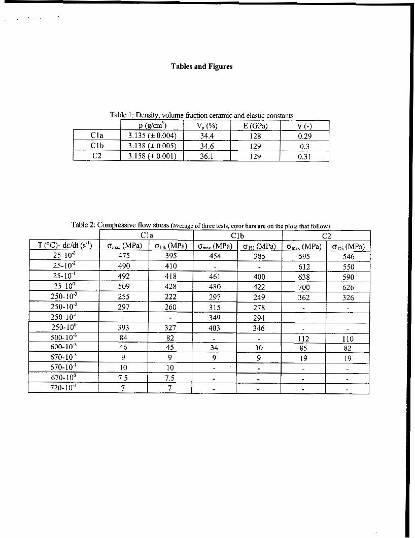
The measured density and calculated ceramic volume hctions. in the as-cast composites are given in Table 1. Values are averages of at least ten measurements. A variation in density fi-om sample to sample, which is not statistical in nature, was noted: the density, and thus the ceramic volume fi-action varies in the radial direction (perpendicular to the direction of infiltration), decreasing fi-om the exterior to the interior of the casting. This variation is small, however, with a maximum measured difference on the order of 1.5 vol.% a03.
Compressive behavior
Curves displaying typical compressive responses of the present composites for various testing conditions are given in Fig. 2. Table 2 Sumtnarizes the results of the compression tests in terms of the peak stress attained, and the stress at 1% reference strain (given that the peak stress does not occur at a set strain for each testing condition). The elastic constants measured by ultrasonic vibration can be found in Table 1. It should be noted that all plotted and tabulated values are absolute values of true stress and true strain.
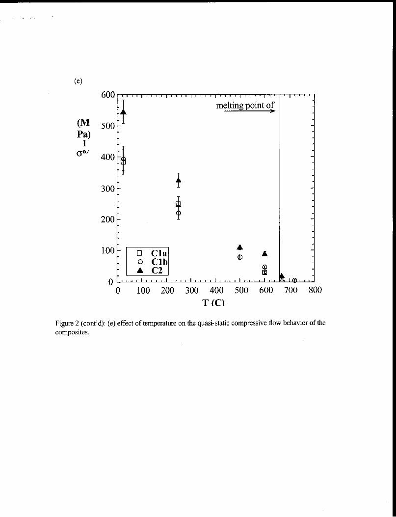
GeneraZ trends: The compressive flow stress of the present composites decreases as the temperature is increased to the melting point of the matrix. On the other hand, increasing the strain-rate serves to increase the compressive flow stress and this strain-rate dependence is greater at higher temperatures. The composites, thus, respond to mriations in temperature and strain-rate in a m e r similar to that observed for pure aluminum, usually understood in light of

thermally activated components in dislocation motion. These findings are in agreement with the literature, in which composites with a strain-rate sensitive matrix are also found to be strain-rate sensitive (conversely, matrix metals that are not strain-rate sensitive typically result in composites that are not sensitive to strain-rate).
At temperatures above the melting point of the A1 matrix, however, both the temperature and the strain-rate dependence of the flow stress disappear, within the experimental error of the measurements. In contrast, thixotropic materials display a decrease in flow stress with increasing strain rate, due to the competing processes of agglomeration and deagglomeration of the solid phase under the influence of strain. In the present materials, the solid phase deagglomerates under the influence of strain (see below) but there is no physical mechanism (such as local melting or “welding” of the solid phase in thixotropic alloy systems) to accommodate re- agglomeration. It would seem that some solubility of the solid phase in the liquid is also necessary for agglomeration processes (or coarsening) to be operative on the time scale of straining. The rate of straining, thus, does not seem to be a determining parameter in the behavior of pure aluminum-matrix composites above the melting point of aluminum.
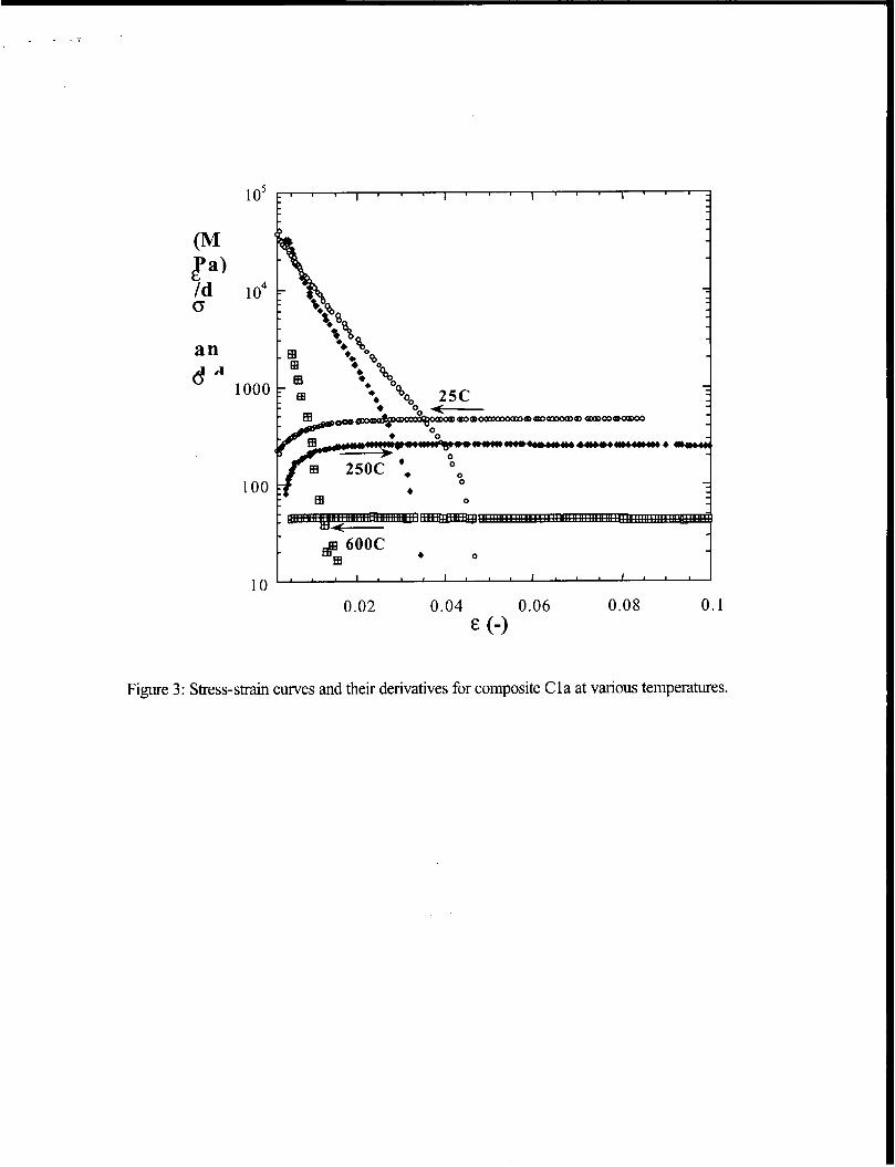
A common feature of all stress-strain curves is the existence of a peak stress after which the values of stress continuously decreases. This peak stress can be determined by taking the derivative of the stress-strain curve and finding its intersection with the stress-strain curve (do/de: = 0, which is a geometric &ability criterion called the Considere criterion), Fig. 3. Interestingly, the strain at which this peak stress (or “instability stress” according to the Considere criterion nomenclature) occurs is also a hc t ion of temperature and strain rate; it decreases with increasing temperature, Fig. 3, and increases with increasing strain-rate.
Effect of volume fraction: The effect of varying the volume hction ceramic in the investigated materials is noted both in Fig. 3 and Table 2; increasing their volume fi-action serves to increase their compressive strength (material Cla and Clb versus C2). The fact that a difference in volume fraction of close to 2% can result in an increase in flow stress on the order of 25% (for the peak stress at 25 “C and lo” s-’), indicates the importance of dispersion strengthening in the deformation behavior of these materials; dispersion strengthening is highly sensitive to the interparticle distance, A, which in turn is sensitive to the volume hction of particles (particularly in this high volume fmction regime).
Preform behavior: Compressive stress-strain curves of the ceramic preform prior to infiltration (Pl) do not display significant variation between room temperature and 670 “C, Fig. 4; an average compressive strength of 17 MPa for the ceramic preforms was determined. This value is slightly higher but close to the average compressive strength of its corresponding composites (C 1 a and C 1 b) above the melting point of the matrix, which is 9 f 2 MPa.
Macroscopic failure characteristics: Macroscopic fracture of the compressive samples at room temperature OCCUTS shortly after the peak stress has been attained, through a single shear crack located at approximately 45 O to the compression axis. At temperatures above the melting

point of Al multiple cracking occurs at precisely the maximum stress and these cracks are situated parallel to the compression axis and with a preference towards the exterior of the samples-a phenomenon very similar to spallation. At the intermediate temperatures of 250 "C and 500 "Cy relatively large compressive strains (20-30%) can be imposed on the samples without the appearance of macrocracks. The strains at which cracks fnally appear are much greater than the strain at which the peak stress occurs. These cracks are located on the surface of the midsection of the samples-probably a product of specimen barreling that is inevitable at large strains. At 600 "Cy the composites display no predominant fracture mode; cracks appear shortly after the peak stress either at 45 " or parallel to the compression axis. The described failure modes at a given temperature are not affected by the imposed strain rate. The preform, finally, fixtures by the simultaneous propagation of several cracks with a mixed character; the cracks have segments both parallel and at a specific angle (not necessarily 45 ") to the compression axis. Cracking occurs at precisely the maximum attained stress.
Dissolution experiments: The strain at which the maximum stress occurs was chosen as a reference strain; several samples from the three composite castings were quasistatically compressed (1 0" s") at various temperatures, to strains less than or greater than this reference strain. For samples that were deformed to strains greater than this reference strain (regardless of testing temperature and imposed strain rate), complete dissolution of the matrix was possible and the reinforcement settled to the bottom of the beaker, in which the dissolution took place, in the form of a powder; an indication that for those samples the reinforcement was no longer interconnected. For samples that were deformed to strains smaller than this reference strain, complete dissolution of the matrix was impossible and a residual inner core of metal was always present. In the exterior of the samples, however, were dissolution of the matrix did take place the reinforcement remained interconnected and there was no evidence of accumulated ceramic powder at the bottom of the beaker. The maximum in the compressive stress-strain curve of the present composites is, thus, somehow related to the loss of long-range interconnectivity of the reinforcing ceramic phase. Whether the loss of interconnectivity is a product of this peak stress or vice versa is not yet clear.
Effect of prestraining at a different temperature: Three samples fi-om the C1 castings were deformed at 500 "C to strains slightly greater than the strain corresponding to the maximum stress (this temperature was chosen due to the low probability of macrocracking). After this prestraining, the samples were cooled down and subsequently tested at room temperature, 250 "C and 670 "C. At all temperatures the prestrained samples join the compressive curves of as- cast samples, which were monotonically tested at the same strain rate s-'). This would indicate that for the given composite microstructure contiguity of the reinforcing phase plays a negligible role on plastic flow. It is rather the characteristic length scale of the microstructure (the interparticle distance for example), and its interaction with dislocation motion, which dominates the deformation behavior. This length scale should not change drastically with the loss of ceramic interconnectivity. Furthermore, the shape of the stress-strain curves of the prestrained samples is the same as those of the as-cast samples; a maximum in stress occurs after which the stress continuously decreases. This would seem to indicate that the maximum in the stress-strain

curve does not occur due to the loss of interconnectivity of the reinforcement. Rather, another mechanism (or combination of mechanisms) becomes operative at that point leading to the breakdown of the ceramic network.
whether or not interconnectivity of the ceramic phase influences the elastic constants of these materials is not yet clear-neither experimentally nor theoretically. Measurements of the elastic constants on three samples (one from each casting) deformed to 15% strain at 250 "C revealed a 23% decrease in the Young's modulus. These results are, however, non conclusive since this decrease in modulus was also accompanied by a decrease in density of the samples in the range of 0.6 and 0.9%. This density decrease is primarily a product of microstructural damage accumulation in the form of matrix voiding, as revealed by SEM images of the compressed samples, Fig. 6. To distinguish the effects of interconnectivity and damage, we plan to determine the elastic constants of samples deformed to s& only slightly greater than the strain at which the maximum stress occurs (roughly 3% at temperatures between 250 "C and 500 "C). At such small strains, the amount of accumulated damage is expected to be minimal.
Strain late histmy effects: Samples of casting Cla and Clb where compressed at 250 "Cy initially under high strain rate conditions (lo-' s-l and 10' s-'), immediately followed by quasi- static reloading (lo" s-l), Fig. 7. The differences between the flow stress cf'the reloaded samples and the uninterrupted quasistatic flow stress are small; however, the flow curves of the reloaded specimens tend to be somewhat lower than in the as-cast sample. Similarly, a sample reloaded at 250 "C after deforming at room temperature and thus at higher stress, displayed a lower flow stress compared to quasistatic loading at 250 "Cy Fig. 7. One possible explanation for both of these observations is that damages accumulates with strain and is dependent on the flow stress.
Conclusions :
+ Materials produced by infiltration of sintered &03 preforms by liquid Al are homogeneous both macroscopically and microscopically. However, they display a certain amount of structuring on the meso- scale, in the form of spherical sintered bodies on the order of 100 lm, which are surrounded by unreinforced Al "veins".
+ These materials are strain-rate dependent at room temperature and at 250 "Cy their strain- rate sensitivity being higher at higher temperatures. Above the melting point of the matrix, and thus in the semi-solid state, this strain-rate dependency disappears. In other words, these materials do not appear to be thixotropic. The stresses needed to deform them in the semi-solid state are relatively low (lOMPa), but cracking is evident early on in the deformation history. It is worth stressing, however, that these are results for testing under a uniaxial pressure and it is unclear what the effect of a superimposed hydrostatic pressure (common in thixoforming or any forming process) would be.

+ The fact that the reinforcement in these materials is interconnected has no bearing on their flow behavior in both the solid and the semi-solid state. Disruption of this interconnectivity during straining or forming should not affect the mechanical properties of these composites at low or high temperature.
+ Damage accumulates during plastic deformation of the composites primarily in the form of matrix voids, and the amount of damage seems to depend on flow stress (and thus strain rate).
Tables and Figures
Table 1 : Density, volume hction ceramic and elastic constants
Cla 3.135 (f 0.004) 34.4 128 0.29 Clb 3.138 (f 0.005) 34.6 129 0.3
P (g/cm3> v, (%) E (GPa) v (-1
I C2 I 3.158 (f0.001) I 36.1 I 129 I 0.31 I
Table 2: Compressive flow stress (average of three tests, error bars are on the plots that follow) Cla C lb c 2
_______~
T (“C)- dddt (s-I) Omax (MPa) 01% (MPa) Omax (MPa) 01% (MPa) Omax (MPa) 01% (MPa) 25- 10” 475 395 454 385 595 546 25- 1 0-2 490 410 - - 612 550

Figure 1: Microstructure of as-cast composite Clb; (a) optical micrograph (Al is the lighter phase) and (b) scanning electron micrograph (Al is the darker phase).

600
500
400
300
200
100 p
Cla
400
300
200
100
n v
0 0.05 0.1
E (-1 0.15
Figure 2: (a) Typical flow curves for composites C1 and C2 at room temperature and (b) effect of strain-rate on compressive behavior of composite Clb at 250 "C.
600
500
400
300
200
100 0.0001 0.001 0.01 0.1 1 10
dddt (s')
15
E s D 3
10
5
0 0.0001 0.001 0.01 0.1 1 10
dddt (S -1)
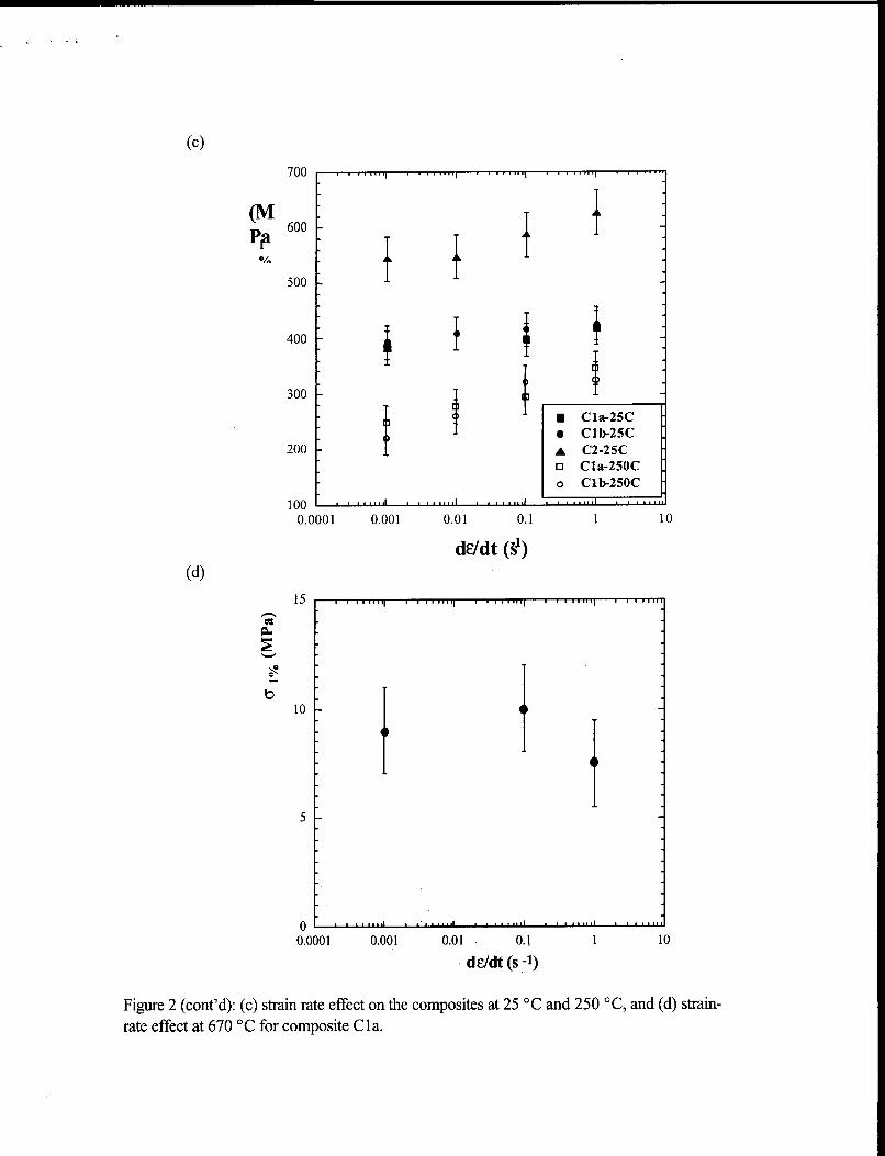
Figure 2 (cont'd): (c) strain rate effect on the composites at 25 "C and 250 "C, and (d) strain- rate effect at 670 "C for composite Cla.
. . . I
- 1 A C 2 I
ii 500
40011 200 3001
1.
I
melting point of
A a i
Figure 2 (cont'd): (e) effect of temperature on the quasi-static compressive flow behavior of the composites.
B a
1 o5
1 o4
1000
100
1 0 ' . ' ' ' ' ' ' ' ' ' ' I ' ' ' I ' ' ' ' 0.02 0.04 0.06 0.08 0.1
E (-1
Figure 3: Stress-strain curves and their derivatives for composite Cla at various temperatures.

25
(M ga
20
15
10
5
0
Figure 4: Compressive stress- strain curves of ceramic preform P 1.

. . . .
Figure 6: Matrix voiding after plastic straining at 250 "C in composite Cla.

25C-103 6'
L e- I A 25OC-16 S' 4001 e ?- *
300
200
100
0 ' ' ' I ' ' ' ' I ' ' ' ' ' ' ' ' ' ' 0 0.05 0.1 0.15 0.2
E (-1
Figure 7: Effect of strain-rate histoy on the compressive flow behavior of composite Clb.
. . . (
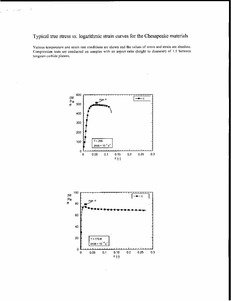
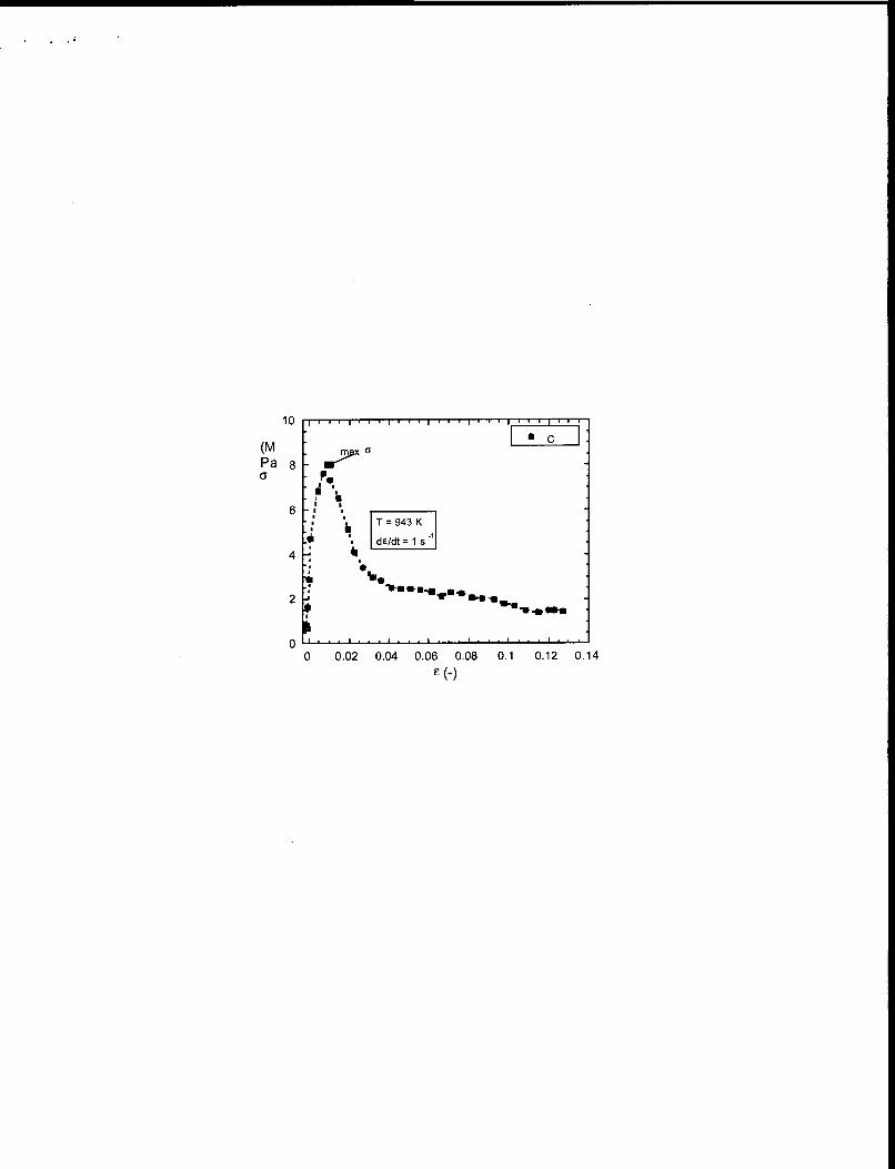
Typical true stress vs. logarithmic strain curves for the Chesapeake materials
Various temperature and strain rate conditions are shown and the values of stress and strain are absolute. Compression tests are conducted on samples with an aspect ratio (height to diameter) of 1.5 between tungsten carbide platens.
300
200
100
0 0 0.05 0.1 0.15 0.2 0.25 0.3
E (-1
1
0 0.05 0.1 0.15 0.2 0.25 0.3 E (4
6
A
2
0 0 0.02 0.04 0.06 0.08 0.1 0.12 0.14
E (-)

Subject
Engine test with Chesapeake piston;
Piston type- 7961 Engine: 85 KW; W; supercharged Test type: 2 point endurance test
Distribution list
A. Brawn t. Hofmann s. Barnes
Circulate: JHa, AM61
--" Y --__-
Reason of investigation
Cnessapeake cornp~sit dispersoids ombedded inro a Aturninurn matri Gf! p!storrs, Due to the exceknt hcgh temper hstand at ioadsng candttions where cast AI pistans fail,
Hovtever. the first Chesapeake piston has failed after 60 t~ testrng time.
Tatget
Find out the reason for failure and investtgate the pistan on further details of Chesapeake suitability as pistan material

Failure Mode
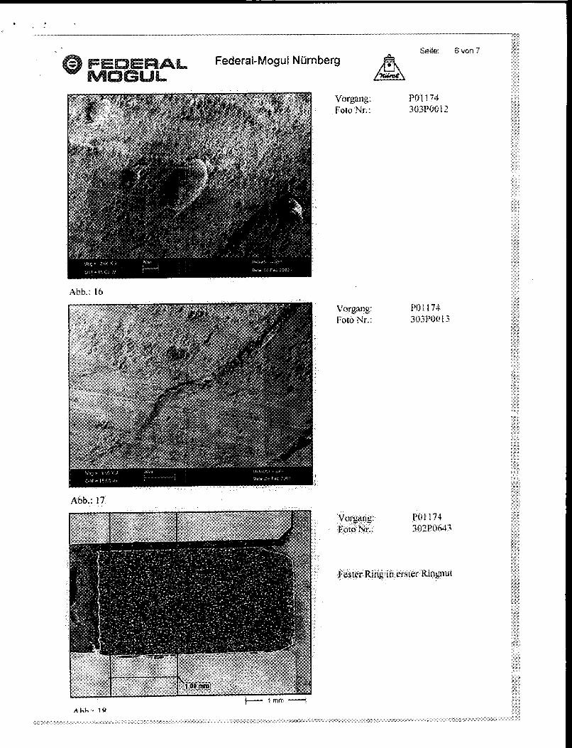
i Cracking has occured at the pin bore piam the area of highest mechanic& load,ng (see Flg 4 1 ;. The c r a ~ k s were initiated at both pin axis > 3 different ~~r~~~~~~ (named I. I l l ) were found at the fracture surface (sa2 Fig 2).
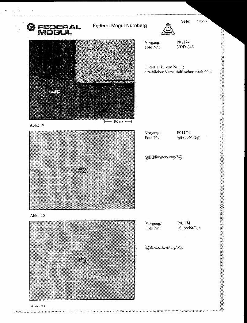
es sf the bawl edge (see Fig. *1j
I Mainly cracking at some plaees (see
of highest stresses, but deflection of crack to granular surfaces at
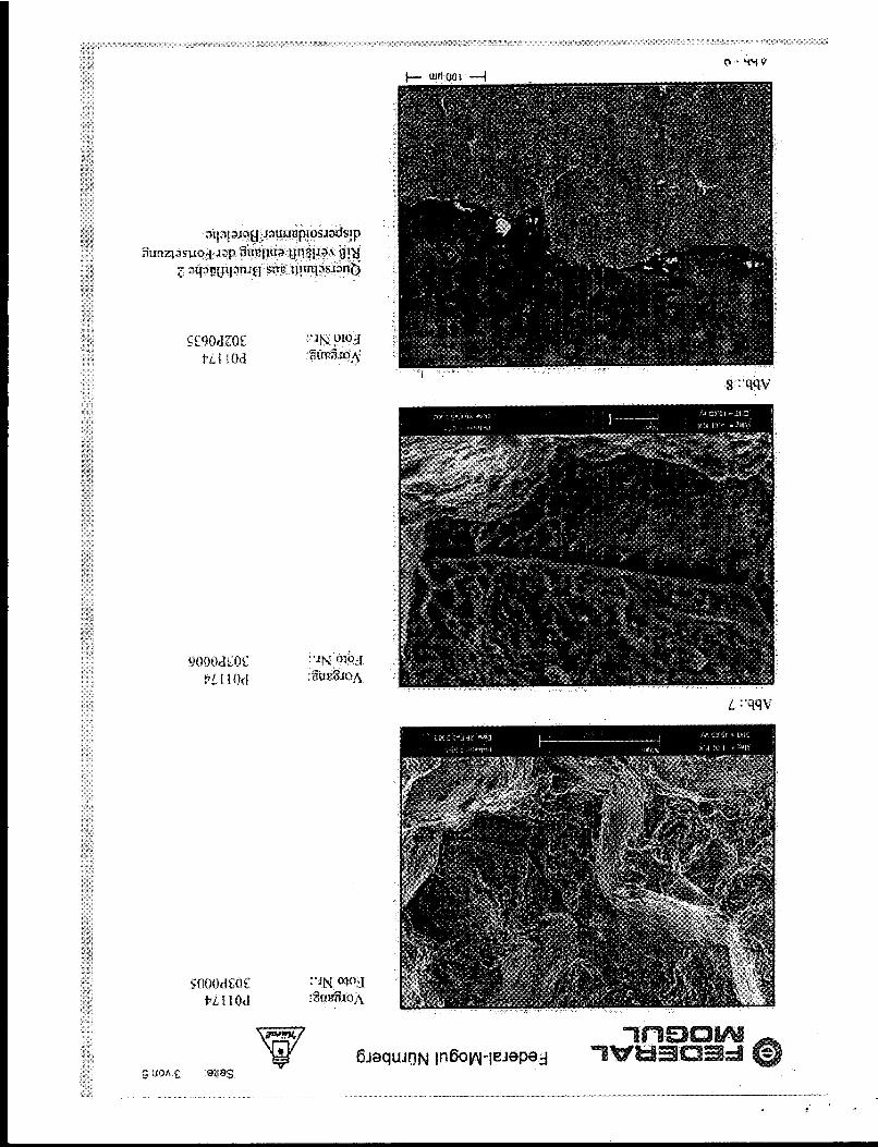
granule surf;3css, Sire of the granuk
Crack has foilowed the plane of highest stresses w ucture [see Fig 5).
ree areas can be related to:
I . Crack inrtitiitian gh x law rates 1 8 Crack propagat wre 5
111 C r x k propqetron at low temperatures I very high rates
lnhsmsneneities
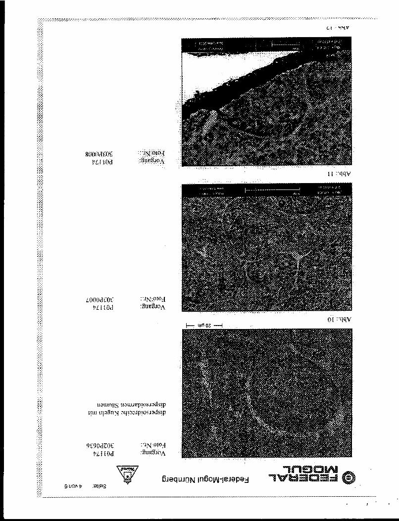
The fractured piston sho ;. Preferred crack pi L T y p I and t l fract ructure of hard granules embedded inta a softer matrix
[sa@ Ftg li,. ,8) news structure of the piston material (see FIQ B - 22) ture be closely related 40 the granular structure ai the 9 This i n h ~ f l i ~ ~ ~ ~
fracture surface i. Earlier investigations on Chesapeake nitaterial have revealed a s:tuctu:r: of dispersoid rich
granules ~ ~ b ~ ~ d ~ d inta 8 dispersoid paar matrix, too (sse FIB 13)
at consists of harder and softer areas, resulting jn locai~ed plastic n and crack p r ~ ~ ~ ~ ~ ~ i o n at sphericat surfaces
Crack initiation
'r ftre locations of
prn after anly 60 h engine testing
Re candAions at the ftrst ring groove oduced witnoua a soIution for ring groooue
reinfarcement
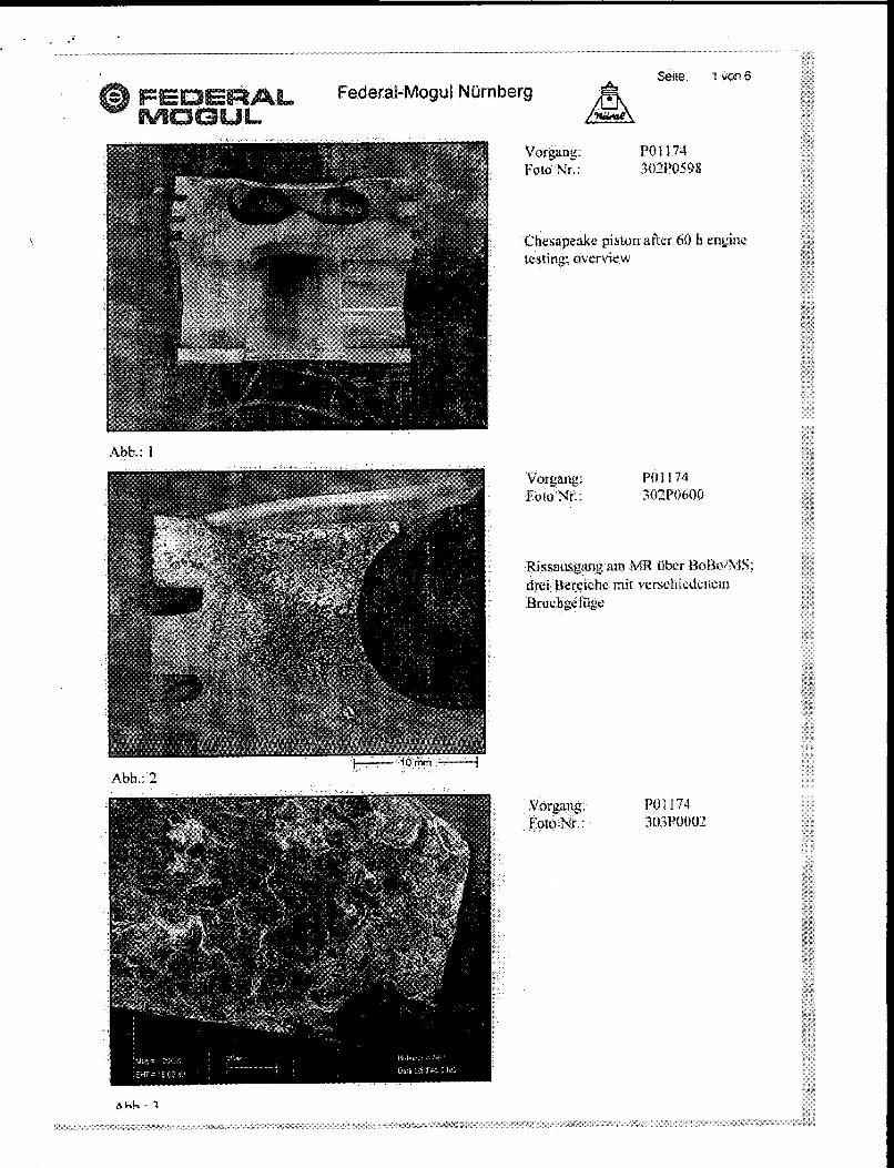
SO h engine
dbb,: 1

. . -~
*rta 2vran6 Federal -M og u I N ij m berg
AM.: 9
C l . Y Y V
. .

Selta 5von 6 Federal-Mug ul Nil rnberg
Abb.: 13
Ahb.: 14
d h h - t i
Rbb.: 16
Abb.: 17
Ahh.: 19
Abb.: 20