Dodge SX2.0 Chassis Diagnostics Manual.pdf
52
TABLE OF CONTENTS 1.0 INTRODUCTION .........................................................1 1.1 SYSTEM COVERAGE ...............................................1 1.2 SIX-STEP TROUBLESHOOTING PROCEDURE ..........................1 2.0 IDENTIFICATION OF SYSTEM .............................................1 3.0 SYSTEM DESCRIPTION AND FUNCTIONAL OPERATION ......................1 3.1 TEVES MARK 20e SYSTEM DESCRIPTION .............................1 3.1.1 PEDAL FEEL/VEHICLES CHARACTERISTICS ...................2 3.1.2 SYSTEM COMPONENTS .....................................2 3.1.3 ABS AND RED BRAKE WARNING INDICATOR ...................2 3.1.4 CONTROLLER ANTILOCK BRAKE (CAB) .......................3 3.1.5 HYDRAULIC CONTROL UNIT .................................3 3.1.6 SENSORS .................................................3 3.2 ABS DIAGNOSTIC TROUBLE CODES ..................................4 3.2.1 SYSTEM INITIALIZATION ....................................4 3.2.2 DIAGNOSTIC MODE ........................................4 3.2.3 INTERMITTENT DIAGNOSTIC TROUBLE CODES ................4 3.3 FREEZE FRAME ....................................................4 3.4 USING THE DRBIIIT .................................................4 3.5 DRBIIIT ERROR MESSAGES .........................................4 3.5.1 DRBIIIT DOES NOT POWER UP (BLANK SCREEN)...............5 3.5.2 DISPLAY IS NOT VISIBLE ....................................5 4.0 DISCLAIMERS, SAFETY, WARNINGS .......................................5 4.1 DISCLAIMERS......................................................5 4.2 SAFETY ...........................................................5 4.2.1 TECHNICIAN SAFETY INFORMATION ..........................5 4.2.2 VEHICLE PREPARATION FOR TESTING ........................5 4.2.3 SERVICING SUB—ASSEMBLIES ..............................5 4.2.4 DRBIIIT SAFETY INFORMATION ..............................6 4.3 WARNING .........................................................6 4.3.1 VEHICLE DAMAGE WARNINGS ...............................6 4.3.2 ROAD TESTING A COMPLAINT VEHICLE .......................6 4.4 DIAGNOSIS ........................................................6 5.0 REQUIRED TOOLS AND EQUIPMENT ......................................7 6.0 GLOSSARY OF TERMS...................................................7 7.0 DIAGNOSTIC INFORMATION AND PROCEDURES ............................9 BRAKES (CAB) BUS SYSTEM COMMUNICATION FAILURE .................................10 CAB INTERNAL FAILURE ................................................12 CLUSTER LAMP FAILURE................................................14 LEFT FRONT SENSOR CIRCUIT FAILURE ..................................16 LEFT REAR SENSOR CIRCUIT FAILURE ...................................16 RIGHT FRONT SENSOR CIRCUIT FAILURE .................................16 RIGHT REAR SENSOR CIRCUIT FAILURE ..................................16 LEFT FRONT WHEEL SPEED SIGNAL FAILURE .............................21 i
description
Diagnostics Manual for 2004 Dodge SX2.0
Transcript of Dodge SX2.0 Chassis Diagnostics Manual.pdf

TABLE OF CONTENTS
1.0 INTRODUCTION . . . . . . . . . . . . . . . . . . . . . . . . . . . . . . . . . . . . . . . . . . . . . . . . . . . . . . . . .1
1.1 SYSTEM COVERAGE . . . . . . . . . . . . . . . . . . . . . . . . . . . . . . . . . . . . . . . . . . . . . . .11.2 SIX-STEP TROUBLESHOOTING PROCEDURE . . . . . . . . . . . . . . . . . . . . . . . . . .1
2.0 IDENTIFICATION OF SYSTEM . . . . . . . . . . . . . . . . . . . . . . . . . . . . . . . . . . . . . . . . . . . . .1
3.0 SYSTEM DESCRIPTION AND FUNCTIONAL OPERATION . . . . . . . . . . . . . . . . . . . . . .1
3.1 TEVES MARK 20e SYSTEM DESCRIPTION . . . . . . . . . . . . . . . . . . . . . . . . . . . . .13.1.1 PEDAL FEEL/VEHICLES CHARACTERISTICS . . . . . . . . . . . . . . . . . . .23.1.2 SYSTEM COMPONENTS. . . . . . . . . . . . . . . . . . . . . . . . . . . . . . . . . . . . .23.1.3 ABS AND RED BRAKE WARNING INDICATOR. . . . . . . . . . . . . . . . . . .23.1.4 CONTROLLER ANTILOCK BRAKE (CAB) . . . . . . . . . . . . . . . . . . . . . . .33.1.5 HYDRAULIC CONTROL UNIT . . . . . . . . . . . . . . . . . . . . . . . . . . . . . . . . .33.1.6 SENSORS . . . . . . . . . . . . . . . . . . . . . . . . . . . . . . . . . . . . . . . . . . . . . . . . .3
3.2 ABS DIAGNOSTIC TROUBLE CODES . . . . . . . . . . . . . . . . . . . . . . . . . . . . . . . . . .43.2.1 SYSTEM INITIALIZATION . . . . . . . . . . . . . . . . . . . . . . . . . . . . . . . . . . . .43.2.2 DIAGNOSTIC MODE . . . . . . . . . . . . . . . . . . . . . . . . . . . . . . . . . . . . . . . .43.2.3 INTERMITTENT DIAGNOSTIC TROUBLE CODES . . . . . . . . . . . . . . . .4
3.3 FREEZE FRAME. . . . . . . . . . . . . . . . . . . . . . . . . . . . . . . . . . . . . . . . . . . . . . . . . . . .43.4 USING THE DRBIIIT . . . . . . . . . . . . . . . . . . . . . . . . . . . . . . . . . . . . . . . . . . . . . . . . .43.5 DRBIIIT ERROR MESSAGES . . . . . . . . . . . . . . . . . . . . . . . . . . . . . . . . . . . . . . . . .4
3.5.1 DRBIIIT DOES NOT POWER UP (BLANK SCREEN). . . . . . . . . . . . . . .53.5.2 DISPLAY IS NOT VISIBLE . . . . . . . . . . . . . . . . . . . . . . . . . . . . . . . . . . . .5
4.0 DISCLAIMERS, SAFETY, WARNINGS . . . . . . . . . . . . . . . . . . . . . . . . . . . . . . . . . . . . . . .5
4.1 DISCLAIMERS. . . . . . . . . . . . . . . . . . . . . . . . . . . . . . . . . . . . . . . . . . . . . . . . . . . . . .54.2 SAFETY . . . . . . . . . . . . . . . . . . . . . . . . . . . . . . . . . . . . . . . . . . . . . . . . . . . . . . . . . . .5
4.2.1 TECHNICIAN SAFETY INFORMATION . . . . . . . . . . . . . . . . . . . . . . . . . .54.2.2 VEHICLE PREPARATION FOR TESTING. . . . . . . . . . . . . . . . . . . . . . . .54.2.3 SERVICING SUB—ASSEMBLIES . . . . . . . . . . . . . . . . . . . . . . . . . . . . . .54.2.4 DRBIIIT SAFETY INFORMATION . . . . . . . . . . . . . . . . . . . . . . . . . . . . . .6
4.3 WARNING . . . . . . . . . . . . . . . . . . . . . . . . . . . . . . . . . . . . . . . . . . . . . . . . . . . . . . . . .64.3.1 VEHICLE DAMAGE WARNINGS . . . . . . . . . . . . . . . . . . . . . . . . . . . . . . .64.3.2 ROAD TESTING A COMPLAINT VEHICLE . . . . . . . . . . . . . . . . . . . . . . .6
4.4 DIAGNOSIS . . . . . . . . . . . . . . . . . . . . . . . . . . . . . . . . . . . . . . . . . . . . . . . . . . . . . . . .6
5.0 REQUIRED TOOLS AND EQUIPMENT . . . . . . . . . . . . . . . . . . . . . . . . . . . . . . . . . . . . . .7
6.0 GLOSSARY OF TERMS . . . . . . . . . . . . . . . . . . . . . . . . . . . . . . . . . . . . . . . . . . . . . . . . . . .7
7.0 DIAGNOSTIC INFORMATION AND PROCEDURES . . . . . . . . . . . . . . . . . . . . . . . . . . . .9
BRAKES (CAB)BUS SYSTEM COMMUNICATION FAILURE . . . . . . . . . . . . . . . . . . . . . . . . . . . . . . . . .10CAB INTERNAL FAILURE . . . . . . . . . . . . . . . . . . . . . . . . . . . . . . . . . . . . . . . . . . . . . . . .12CLUSTER LAMP FAILURE. . . . . . . . . . . . . . . . . . . . . . . . . . . . . . . . . . . . . . . . . . . . . . . .14LEFT FRONT SENSOR CIRCUIT FAILURE . . . . . . . . . . . . . . . . . . . . . . . . . . . . . . . . . .16LEFT REAR SENSOR CIRCUIT FAILURE . . . . . . . . . . . . . . . . . . . . . . . . . . . . . . . . . . .16RIGHT FRONT SENSOR CIRCUIT FAILURE . . . . . . . . . . . . . . . . . . . . . . . . . . . . . . . . .16RIGHT REAR SENSOR CIRCUIT FAILURE . . . . . . . . . . . . . . . . . . . . . . . . . . . . . . . . . .16LEFT FRONT WHEEL SPEED SIGNAL FAILURE . . . . . . . . . . . . . . . . . . . . . . . . . . . . .21
i

TABLE OF CONTENTS - Continued
LEFT REAR WHEEL SPEED SIGNAL FAILURE . . . . . . . . . . . . . . . . . . . . . . . . . . . . . .21RIGHT FRONT WHEEL SPEED SIGNAL FAILURE . . . . . . . . . . . . . . . . . . . . . . . . . . . .21RIGHT REAR WHEEL SPEED SIGNAL FAILURE . . . . . . . . . . . . . . . . . . . . . . . . . . . . .21PUMP CIRCUIT FAILURE . . . . . . . . . . . . . . . . . . . . . . . . . . . . . . . . . . . . . . . . . . . . . . . .24SYSTEM OVER VOLTAGE. . . . . . . . . . . . . . . . . . . . . . . . . . . . . . . . . . . . . . . . . . . . . . . .28SYSTEM UNDER VOLTAGE . . . . . . . . . . . . . . . . . . . . . . . . . . . . . . . . . . . . . . . . . . . . . .31VALVE POWER FEED FAILURE . . . . . . . . . . . . . . . . . . . . . . . . . . . . . . . . . . . . . . . . . . .33
COMMUNICATION*NO RESPONSE FROM CONTROLLER ANTILOCK BRAKE . . . . . . . . . . . . . . . . . . . .36
VERIFICATION TESTSVERIFICATION TESTS . . . . . . . . . . . . . . . . . . . . . . . . . . . . . . . . . . . . . . . . . . . . . . . . . . .38
8.0 COMPONENT LOCATIONS . . . . . . . . . . . . . . . . . . . . . . . . . . . . . . . . . . . . . . . . . . . . . . .39
8.1 CONTROLLER ANTILOCK BRAKE . . . . . . . . . . . . . . . . . . . . . . . . . . . . . . . . . . . .398.2 DATA LINK CONNECTOR . . . . . . . . . . . . . . . . . . . . . . . . . . . . . . . . . . . . . . . . . . .398.3 FUSES . . . . . . . . . . . . . . . . . . . . . . . . . . . . . . . . . . . . . . . . . . . . . . . . . . . . . . . . . . .398.4 HYDRAULIC CONTROL UNIT . . . . . . . . . . . . . . . . . . . . . . . . . . . . . . . . . . . . . . . .408.5 PUMP MOTOR . . . . . . . . . . . . . . . . . . . . . . . . . . . . . . . . . . . . . . . . . . . . . . . . . . . .408.6 TONE WHEELS. . . . . . . . . . . . . . . . . . . . . . . . . . . . . . . . . . . . . . . . . . . . . . . . . . . .408.7 WHEEL SPEED SENSORS . . . . . . . . . . . . . . . . . . . . . . . . . . . . . . . . . . . . . . . . . .418.8 WHEEL SPEED SENSOR CONNECTORS. . . . . . . . . . . . . . . . . . . . . . . . . . . . . .42
9.0 CONNECTOR PINOUTS . . . . . . . . . . . . . . . . . . . . . . . . . . . . . . . . . . . . . . . . . . . . . . . . .43
ABS PUMP MOTOR - 2 WAY. . . . . . . . . . . . . . . . . . . . . . . . . . . . . . . . . . . . . . . . . . . . . .43BRAKE LAMP SWITCH - BLACK 6 WAY . . . . . . . . . . . . . . . . . . . . . . . . . . . . . . . . . . . .43CONTROLLER ANTILOCK BRAKE - BLACK 24 WAY . . . . . . . . . . . . . . . . . . . . . . . . . .43DATA LINK CONNECTOR - WHITE 16 WAY . . . . . . . . . . . . . . . . . . . . . . . . . . . . . . . . .44LEFT FRONT WHEEL SPEED SENSOR - BLACK 2 WAY . . . . . . . . . . . . . . . . . . . . . .44LEFT REAR WHEEL SPEED SENSOR - BLACK 2 WAY. . . . . . . . . . . . . . . . . . . . . . . .44RIGHT FRONT WHEEL SPEED SENSOR - BLACK 2 WAY . . . . . . . . . . . . . . . . . . . . .44RIGHT REAR WHEEL SPEED SENSOR - BLACK 2 WAY . . . . . . . . . . . . . . . . . . . . . .45
10.0 SCHEMATIC DIAGRAMS . . . . . . . . . . . . . . . . . . . . . . . . . . . . . . . . . . . . . . . . . . . . . . . . .47
TEVES MARK 20e CONTROLLER ANTILOCK BRAKE – ABS . . . . . . . . . . . . . . . . . . 47
ii

1.0 INTRODUCTION
The procedures contained in this manual includeall the specifications, instructions, and graphicsneeded to diagnose 2004 Chrysler and Dodge NeonMark 20e Antilock Braking System (ABS) prob-lems. The diagnostics in this manual are based onthe failure condition or symptom being present attime of diagnosis.
Follow the recommendations below when choos-ing your diagnostic path.1. First make sure the DRBIIIt is communicating
with the CAB. If the DRBIIIt displays a “NoResponse” condition, you must diagnose thatfirst.
2. Read and record DTC’s (diagnostic trouble codes)and Freeze Frame information with theDRBIIIt.
3. If no DTC’s are present, identify the customercomplaint.
4. Once the DTC or customer complaint is identi-fied, locate the matching test in the Table ofContents and begin to diagnose the symptom.
All component location views are in Section 8.0.All connector pinouts are in Section 9.0. All sche-matics are in Section 10.0.
An * placed before the symptom description indi-cated a customer complaint.
When repairs are required, refer to the appropri-ate service manual for the proper removal andrepair procedure.
Diagnostic procedures change every year. Newdiagnostic systems may be added; carry over sys-tems may be enhanced. READ THIS MANUALBEFORE TRYING TO DIAGNOSE A VEHICLECODE. It is recommended that you review theentire manual to become familiar with all new andchanged diagnostic procedures.
After using this book, if you have any commentsor recommendations, please fill out the form at theback of the book and mail it back to us.
1.1 SYSTEM COVERAGE
This diagnostic procedure manual covers theTeves Mark 20e Antilock Braking System (ABS) onthe Neon.
1.2 SIX-STEP TROUBLESHOOTINGPROCEDURE
Diagnosis of the antilock brake system is done insix basic steps:• verification of complaint• verification of any related symptoms• symptom analysis
• problem isolation• repair of isolated problem• verification of proper operation
2.0 IDENTIFICATION OFSYSTEM
Vehicles equipped with the Teves Mark 20e an-tilock brake system can be identified by the pres-ence of the hydraulic control unit located with thecontroller antilock brake (CAB) under the hoodnear the air cleaner housing, or by observing theABS lamp illumination during the bulb check.
3.0 SYSTEM DESCRIPTION ANDFUNCTIONAL OPERATION
3.1 TEVES MARK 20e SYSTEMDESCRIPTION
This section covers the physical and operationaldescriptions, and the diagnostic service proceduresfor the Teves Mark 20e Antilock Brake System. It isthe only antilock brake system (ABS) available onthis vehicle.
The purpose of the antilock brake system is toprevent wheel lockup under braking conditions onvirtually any type of road surface. Antilock brakingis desirable because a vehicle that is stopped with-out locking the wheels retains directional stabilityand some steering capability. This allows the driverto retain greater control of the vehicle during brak-ing.
All vehicles equipped with ABS use ElectronicVariable Brake Proportioning (EVBP) to balancefront-to-rear braking when the brakes are appliedin the partial braking range.
A Controller Antilock Brake (CAB) module isused to monitor wheel speeds and to modulate(control) hydraulic pressure in each brake channelwhen ABS is actuated. The CAB also provides avehicle speed signal (VSS) to the powertrain controlmodule via PCI BUS.
During a non-ABS stop, the system functions as astandard diagonally split configuration. The pri-mary hydraulic system supplies brake fluid pres-sure to the right front and left rear brakes, and thesecondary hydraulic system supplies the right rearand left front brakes. A conventional proportioningvalve is not used. This system uses the existing ABSsolenoids to replace and perform the same functionsthat the proportioning valves do. The CAB has aspecial software program that monitors the wheelspeeds and when certain criteria are met the soft-
1
GENERAL INFORMATION

ware will enable the solenoids to perform the samebrake fluid management control as the proportion-ing valves.
During an ABS stop, the system still uses thediagonal hydraulic split; however, the brake systempressure is further split into four control channels.During ABS operation, all wheels are controlledindependently and are on four separate controlchannels.
During an antilock stop, “wheel lock-up” does notnecessarily mean that the wheel has locked, itmeans only that the wheel is turning slower thanthe vehicle speed. This is called “wheel slip” and isindicated as a percentage. 0% slip means that thewheel is rolling free and 100% slip means that thewheel is locked. The antilock system maintains anaverage of approximately 20% wheel slip.
It is important to remember that the antilockbrake system does not shorten the vehicle stoppingdistance under all driving conditions, but providesimproved control of the vehicle while stopping.Vehicle stopping distance is still dependent on ve-hicle speed, weight, tires, road surface, and otherfactors.
3.1.1 PEDAL FEEL/VEHICLESCHARACTERISTICS
There are several pedal feel/vehicle characteris-tics that are considered normal for antilock brakingthat may require further explanation.
When stopping conditions activate the antilockbrakes, the driver may feel some vibrations/pulsations in the brake pedal and may hear thesolenoid valves clicking and the pump motor run-ning. The vibrations/pulsations are caused by theisolating, building and decaying of brake fluid pres-sure within the brake lines. The ABS system pre-vents complete wheel lock-up, but some wheel slipis required for the best braking performance. Thisslip may result in some tire chirping, depending onthe road surface. This chirping should not be inter-preted as total wheel lock-up. Total wheel lock-upleaves black tire marks on dry pavement. Antilockbraking may leave some light marks.
At the end of an ABS stop, the ABS may functionall the way down to near 0 km/h (0 mph). There maybe a slight brake pedal drop anytime the ABS isdeactivated.
In case of braking on a bumpy surface, the ABSsystem may detect wheel locking tendencies due towheel hop and cycle the ABS. In that event thebrake pedal may pulsate with a perceived loss ofdeceleration. ABS braking may also be activated attimes while on dry pavement with sand, gravel, orother loose debris on the road.
It should be noted that the pulsating pedal feelcharacteristic will not illuminate the brake warning
lamps or set a trouble code that is stored in theController Antilock Brake (CAB). When investigat-ing a hard pedal feel, inspect the sensor and tonewheel teeth for chips/broken teeth, damaged sensorpole tips, excessive runout of the tone wheel, orexcessive air gap.
3.1.2 SYSTEM COMPONENTSANTILOCK BRAKE SYSTEM• controller antilock brake (CAB)• vacuum booster• master cylinder (w/center valves)• hydraulic control unit (HCU)• valve block assembly: 8 valve solenoids (4 inlet
valves, 4 outlet valves)• pump/motor assembly:
1 motor2 pumps
• 4 wheel speed sensor/tone wheel assemblies• ABS warning indicator• fuses and wiring harness• fluid reservoir (integral part of master cylinder
assembly)
3.1.3 ABS AND RED BRAKE WARNINGINDICATOR
The amber ABS warning indicator is located inthe instrument cluster. It is used to inform thedriver that the antilock function has been turned offdue to a system malfunction. The CAB controls thelamp indirectly. The CAB monitors its own func-tions. If the CAB determines that the ABS warningindicator should be on, the CAB sends a messagevia the PCI BUS to the instrument cluster and thecluster turns on the indicator. The indicator willremain lit during every key cycle until the circuit orcomponent fault is repaired and the CAB no longerdetects the fault. After repair of a sensor signalfault or a pump motor fault, the CAB must sense allfour wheels at 25 km/h (15 mph) before it willextinguish the ABS and Indicators.
The Instrument Cluster will illuminate the ABSWarning Indicator if it loses communication withthe CAB.
The red brake warning indicator is located in theinstrument cluster. It can be activated by applica-tion of the parking brake, a leak in the front or rearwheel brake hydraulic circuit which causes themaster cylinder reservoir to be low on fluid, or byturning the ignition switch to the start position.The red brake warning indicator can also be turnedon if the CAB indicates an Electronic Brake Distri-bution (EBD) failure.
2
GENERAL INFORMATION

3.1.4 CONTROLLER ANTILOCK BRAKE(CAB)
The antilock brake controller (CAB) is amicroprocessor-based device that monitors wheelspeeds and controls the antilock functions.
The primary functions of the CAB are:• monitor wheel speeds• detect wheel locking tendencies• detect wheel slip• control fluid pressure modulation to the brakes
during antilock stop and traction control opera-tion
• monitor the system for proper operation• provide communication to the DRBIIIt while in
diagnostic mode• store diagnostic information in non-volatile
memoryThe CAB continously monitors the speed of each
wheel. When a wheel locking tendency is detected,the CAB will command the appropriate valve tomodulate brake fluid pressure in its hydraulic unit.Brake pedal position is maintained during an an-tilock stop by being a closed system with the use of3 accumulators. The CAB continues to control pres-sure in individual hydraulic circuits until a wheellocking tendency is no longer present. The CABturns on the pump/motor during an antilock stop.
The antilock brake system is constantly moni-tored by the CAB for proper operation. If the CABdetects a system malfunction, it can disable theantilock system and turn on the antilock warninglamp. If the antilock function is disabled, the sys-tem will revert to standard base brake systemoperation.
The CAB inputs include the following:• four wheel speed sensors• brake lamp switch• ignition switch• battery voltage• diagnostic communication (PCI BUS)
The CAB outputs include the following:• eight valve/solenoid drivers• pump/motor actuation• ABS warning indicator actuation (PCI BUS)• red brake warning indicator actuation (PCI BUS)• diagnostic communication (PCI BUS)
3.1.5 HYDRAULIC CONTROL UNITThe hydraulic control unit (HCU) contains the
valve block assembly and the pump/motor assem-bly.
Valve Block Assembly: The valve block assem-bly contains inlet valves, outlet valves, and shuttlevalves. The inlet valves are spring-loaded in theopen position and the outlet valves are springloaded in the closed position. During an antilockstop, these valves are cycled to maintain the properslip ratio for each channel. If a wheel locks, the inletvalve is closed to prevent any further pressureincrease. Then the outlet valve is opened to releasethe pressure to the accumulators until the wheel isno longer slipping. Once the wheel is no longerslipping, the outlet valve is closed and the inletvalve is opened to reapply pressure. If the wheel isdecelerating within its predetermined limits (prop-er slip ratio), both valves will close to hold thepressure constant.
Pump Motor Assembly: The pump motor as-sembly provides the extra amount of fluid neededduring antilock braking. The pump is supplied fluidthat is released to the accumulators when the outletvalve is opened during an antilock stop. The pumpis also used to drain the accumulator circuits afterthe antilock stop is complete. The pump is operatedby an integral electric motor. This motor is con-trolled by the CAB. The CAB may turn on the motorwhen an antilock stop is detected. The pump con-tinues to run during the antilock stop and is turnedoff approximately 3-5 seconds after the stop iscomplete. The CAB monitors the pump motor oper-ation internally.
3.1.6 SENSORSWheel Speed Sensors and Tone Wheels: One
wheel speed sensor (WSS) is located at each wheel.The sensor has internal circuitry powered by 12volts from the controller antilock brake (CAB). Thesensor generates and sends a DC voltage signalback to the CAB. The signal is toggled in proportionto the speed of the toothed tone wheel as it passesthe sensor pole. The CAB uses the signal to activateABS functions as required.
Because of the internal circuitry, correctsensor function cannot be determined by aresistance check across the pins of the sensor.
The front wheel sensors are attached to a boss inthe steering knuckle. The tone wheels are an inte-gral part of the front axle shaft. The rear speedsensors are mounted in the caliper adapter plateand the rear tone wheels are an integral part of therear rotor hubs. The wheel speed sensor air gapis NOT adjustable.
Correct antilock system operation is dependenton wheel speed signals from the wheel speed sen-sors. The vehicle’s wheels and tires should all be thesame size and type to generate accurate signals. Inaddition, the tires should be inflated to the recom-mended pressures for optimum system operation.Variations in wheel and tire size or significant
3
GENERAL INFORMATION

variations in inflation pressure can produce inaccu-rate wheel speed signals; however, the system willcontinue to function when using the correct factorymini-spare.
3.2 ABS DIAGNOSTIC TROUBLE CODES
The Teves Mark 20e Antilock Brake System(ABS) module may report any of the followingdiagnostic trouble codes:• BUS System Communication Failure• CAB Internal Failure• Cluster Lamp Failure• Left Front Sensor Circuit Failure• Left Front Wheel Speed Signal Failure• Left Rear Sensor Circuit Failure• Left Rear Wheel Speed Signal Failure• Pump Circuit Failure• Right Front Sensor Circuit Failure• Right Front Wheel Speed Signal Failure• Right Rear Sensor Circuit Failure• Right Rear Wheel Speed Signal Failure• System Over Voltage• System Under Voltage• Valve Power Feed Failure
Diagnostic trouble codes are retained in memoryuntil erased using the DRBIIIt, or automaticallyerased after 255 key cycles or 3500 miles.
3.2.1 SYSTEM INITIALIZATIONSystem initialization starts when the key is
turned to “run”. At this point, the CAB performs acomplete self-check of all electrical components inthe antilock brake systems. The ABS and brakewarning lamps will illuminate for 4 seconds withignition on.
At 20 km/h (12 mph) a dynamic test is performed.This will momentarily run the pump/motor. If dur-ing the dynamic test, the brake pedal is depressed,the driver may feel the test through brake pedalpulsations. This is a normal condition.
If any component sets a trouble code duringsystem initialization or dynamic check, the CABwill illuminate the ABS warning lamp.
3.2.2 DIAGNOSTIC MODEFor a Mark 20e system to enter diagnostic mode,
vehicle speed must be below 10 km/h (6 mph) andno ABS condition present. If vehicle speed is notbelow 10 km/h (6 mph), a “no response” messagecould be displayed by the DRBIIIt. The followingare characteristics of diagnostic mode:
• The amber ABS and red brake warning indicatorwill blink rapidly. If a hard trouble code ispresent, such as a CAB Power Feed Circuitdiagnostic trouble code, the indicator will beilluminated without blinking until the diagnostictrouble condition is corrected.
• Antilock operation is disabled.
3.2.3 INTERMITTENT DIAGNOSTICTROUBLE CODES
If the malfunction is not present while perform-ing a test procedure, the diagnostic procedures willnot locate the problem. In this case, the code canonly suggest an area to inspect. Check for thefollowing:• loose or corroded conditions• damaged components (sensors, tone wheels)• damaged wiring• excessive axle shaft runout• hydraulic system leaks• foundation (non-ABS) brake system problems
If no obvious problems are found, erase diagnostictrouble codes and, with the key on, wiggle the wireharness and connectors. Recheck for codes periodi-cally while working through the system. This pro-cedure may uncover a difficult to locate malfunc-tion.
3.3 FREEZE FRAME
Freeze Frame takes a ‘‘snapshot’’ of specific vehi-cle information the instant an ABS failure is recog-nized and stores this information into the CABmemory. This information can be accessed using theDRBIIIt to help diagnose the fault. Freeze Framewill capture the first time failure or only a newfailure that occurs during the current ignition cycle.
3.4 USING THE DRBIIIT
Refer to the DRBIIIt user’s guide for instructionsand assistance with reading diagnostic troublecodes, erasing diagnostic trouble codes and otherDRBIIIt functions.
3.5 DRBIIIT ERROR MESSAGES
Under normal operation, the DRBIIIt will dis-play one of only two error messages:
– User-Requested WARM Boot or User-Requested COLD Boot
4
GENERAL INFORMATION

If the DRBIIIt should display any other errormessage, record the entire display and call the StarCenter. This is a sample of such an error messagedisplay:
ver: 2.14date: 26 Jul93file: key_itf.ccdate: Jul 26 1993line: 548err. 0x1User-Requested COLD boot
Press MORE to switch between this displayand the application screen.
Press F4 when done noting information.
3.5.1 DRBIIIT DOES NOT POWER UP(BLANK SCREEN)
If the LED’s do not light or no sound is emitted atstart up, check for loose cable connections or a badcable. Check the vehicle battery voltage (data link16-way connector cavity 16). A minimum of 11 voltsis required to adequately power the DRBIIIt. Alsocheck for a good ground at the DLC.
If all connections are proper between theDRBIIIt and the vehicle or other devices, and thevehicle battery is fully charged, an inoperativeDRBIIIt may be the result of faulty cable or vehiclewiring.
3.5.2 DISPLAY IS NOT VISIBLELow temperatures will affect the visibility of the
display. Adjust the contrast to compensate for thiscondition.
4.0 DISCLAIMERS, SAFETY,WARNINGS
4.1 DISCLAIMERS
All information, illustrations, and specificationscontained in this manual are based on the latestinformation available at the time of publication.The right is reserved to make changes at any timewithout notice.
4.2 SAFETY
4.2.1 TECHNICIAN SAFETY INFORMATION
WARNING: ENGINES PRODUCE CARBONMONOXIDE THAT IS ODORLESS, CAUSESSLOWER REACTION TIME, AND CAN LEADTO SERIOUS INJURY. WHEN THE ENGINE ISOPERATING, KEEP SERVICE AREAS WELLVENTILATED, OR ATTACH THE VEHICLEEXHAUST SYSTEM TO THE SHOP EXHAUSTREMOVAL SYSTEM.
Set the parking brake and block the wheels beforetesting or repairing the vehicle. It is especiallyimportant to block the wheels on the vehicle; theparking brake does not hold the front drive wheels.
When servicing a vehicle, always wear eye pro-tection, and remove any metal jewelry such aswatchbands or bracelets that might make an inad-vertent electrical contact.
When diagnosing an antilock brake or speedproportional steering system problem, it is impor-tant to follow approved procedures where applica-ble. These procedures can be found in the servicemanual. Following these procedures is very impor-tant to safety of individuals performing diagnostictests.
4.2.2 VEHICLE PREPARATION FORTESTING
Make sure the vehicle being tested has a fullycharged battery. If it does not, false diagnostic codesor error messages may occur.
4.2.3 SERVICING SUB—ASSEMBLIESSome components of the antilock brake or speed
proportional steering system are intended to beserviced in assembly only. Attempting to remove orrepair certain sub-components may result in per-sonal injury and/or improper system operation.Only those components with approved repair andinstallation procedures in the service manualshould be serviced.
5
GENERAL INFORMATION

4.2.4 DRBIIIT SAFETY INFORMATION
WARNING: EXCEEDING THE LIMITS OF THEDRBIIIT MULTIMETER IS DANGEROUS. ITCAN EXPOSE YOU TO SERIOUS ORPOSSIBLY FATAL INJURY. CAREFULLYREAD AND UNDERSTAND THE CAUTIONSAND THE SPECIFICATION LIMITS.• Follow the vehicle manufacturer’s service speci-
fications at all times.• Do not use the DRBIIIt if it has been damaged.• Do not use the test leads if the insulation is
damaged or if metal is exposed.• To avoid electrical shock, do not touch the test
leads, tips, or the circuit being tested.• Choose the proper range and function for the
measurement. Do not try voltage or current mea-surements that may exceed the rated capacity.
• Do not exceed the limits shown in the table below:
FUNCTION INPUT LIMIT
Volts 0 — 500 peak volts AC0 — 500 volts DC
Ohms (resistance)* 0 — 1.12 megohms
Frequency MeasuredFrequency Generated
0 — 10 kHz
Temperature -58 — 1100° F-50 — 600° C
* Ohms cannot be measured if voltage ispresent. Ohm can be measured only in anon—powered circuit.
• Voltage between any terminal and ground mustnot exceed 500v DC or 500v peak AC.
• Use caution when measuring voltage above 25vDC or 25v AC.
• Use the low current shunt to measure circuits upto 10A. Use the high current clamp to measurecircuits exceeding 10A.
• When testing for the presence of voltage or cur-rent, make sure the meter is functioning cor-rectly. Take a reading of a known voltage orcurrent before accepting a zero reading.
• When measuring current, connect the meter inseries with the lead.
• When using the meter function, keep theDRBIIIt away from spark plug or coil wires toavoid measuring error from outside interference.
4.3 WARNING
4.3.1 VEHICLE DAMAGE WARNINGSBefore disconnecting any control module, make
sure the ignition is “off”. Failure to do so coulddamage the module.
When testing voltage or continuity at any controlmodule, use the terminal side (not the wire end) ofthe connector. Do not probe a wire through theinsulation, this will damage it and eventually causeit to fail because of corrosion.
Use care when performing electrical tests so as toprevent accidental shorting of terminals. Such mis-takes can damage fuses or components. Also, asecond code could be set, making diagnosis of theoriginal problem more difficult.
4.3.2 ROAD TESTING A COMPLAINTVEHICLE
Some complaints will require a test drive as partof the repair verification procedure. The purpose ofthe test drive is to try to duplicate the diagnosticcode or symptom condition.
CAUTION: Before road testing a vehicle, besure that all components are reassembled.During the test drive, do not try to read theDRBIIIT screen while in motion. Do not hangthe DRBIII T from the rear view mirror oroperate it yourself. Have an assistantavailable to operate the DRBIII T.
4.4 DIAGNOSIS
1. Your diagnostic test procedure must begin with athorough visual inspection of the ABS system fordamaged components or disconnected connec-tors. The brake lamps must be operational, andif they are not, repair them prior to continuing.
2. Connect the DRBIIIt to the data link connectorlocated under the dash to the left of the steeringcolumn. If the DRBIIIt does not power up, checkthe power and ground supplies to the connector.
3. Select “Antilock Brakes”. Turn the ignition on. Ifthe DRBIIIt displays “No Response”, performthe proper test.
4. Read and record all ABS diagnostic trouble codesand Freeze Frame information. If the “ValvePower Feed Circuit” diagnostic trouble code ispresent, it must be repaired prior to addressingany other DTC’s. If any additional codes arepresent, proceed to the appropriate test.
5. If there are no diagnostic trouble codes present,select “Inputs/Outputs” and read the brakeswitch input as you press and release the brake
6
GENERAL INFORMATION

pedal. If the display does not match the state ofthe pedal, perform the proper test. If a problemwith the amber “ABS” warning indicator exists,refer to the proper test.
6. If no other problems are found, it will be neces-sary to road test the vehicle. THE DRBIIItMUST NOT BE CONNECTED TO THEDATA LINK CONNECTOR WHEN ROADTESTING FOR PROPER ANTILOCK OP-ERATION. THE SYSTEM IS DISABLEDWHILE IN DIAGNOSTIC MODE. Performseveral antilock stops from above 50 Km/h (30mph) and then repeat steps 2, 3, and 4. If anydiagnostic trouble codes are present, proceed tothe appropriate test.
7. The following conditions should be considered“NORMAL” operation, and no repairs should beattempted to correct them.– Brake pedal feedback during an ABS stop
(clicking, vibrating)– Clicking, groaning or buzzing at 10 Km/h
(6 mph) (drive off self test)– Groaning noise during an ABS stop– Slight brake pedal drop and pop noise when
ignition is initially turned on– Brake pedal ratcheting down at the end of an
ABS stop8. If the complaint is ABS “cycling” at the end of a
stop at low speeds, it may caused by a marginalwheel speed sensor signal. The sensor air gap,tone wheel condition, and/or brakes hanging upare possible causes of this condition.
9. After a road test in which no problems werefound, refer to any Technical Service Bulletinsthat may apply.
5.0 REQUIRED TOOLS ANDEQUIPMENT
DRBIIIt (diagnostic read-out box)jumper wiresohmmetervoltmetertest lamp
6.0 GLOSSARY OF TERMS
ABS antilock brake system
CAB controller antilock brake
DC direct current
DLC data link connector
DRB diagnostic read–out box
EVBP electronic variable brake proportion-ing
HCU hydraulic control unit
HZ Hertz
LF left front
LR left rear
PCI Programmable CommunicationInterference
PCM Powertrain Control Module
PDC power distribution center
P/M pump motor
RF right front
RR right rear
SOL solenoid
WSS wheel speed sensor
7
GENERAL INFORMATION

NOTES
8

7.0
DIAGNOSTIC INFORMATION ANDPROCEDURES
9

Symptom:BUS SYSTEM COMMUNICATION FAILURE
When Monitored and Set Condition:
BUS SYSTEM COMMUNICATION FAILURE
When Monitored: Ignition ON, continuously.
Set Condition: When the CAB does not receive a message from the instrument cluster for10 seconds.
POSSIBLE CAUSES
INTERMITTENT CONDITION
ELECTRO-MECHANICAL INSTRUMENT CLUSTER DTC PRESENT
BUS CIRCUIT OPEN
CAB - INTERNAL FAILURE
TEST ACTION APPLICABILITY
1 Turn the ignition on.With the DRBIIIt, read DTCs.With the DRBIIIt, read Freeze Frame information.With the DRBIIIt, erase DTCs.Turn the ignition off.Turn the ignition on.With the DRBIIIt, read DTCs.Does the DRBIIIt display BUS SYSTEM COMMUNICATION FAILURE?
All
Yes → Go To 2
No → Go To 4
2 Turn the ignition on.With the DRBIIIt, read EMIC DTCs.Does the DRBIIIt display ABS MESSAGE NOT RECEIVED?
All
Yes → Refer to symptom ABS MESSAGE NOT RECEIVED in theBODY/INSTRUMENT CLUSTER category.Perform ABS VERIFICATION TEST - VER 1.
No → Go To 3
10
BRAKES (CAB)

TEST ACTION APPLICABILITY
3 Turn the ignition off.Disconnect the negative (-) battery cable.Disconnect the CAB harness connector.NOTE: check connector - Clean/repair as necessary.Measure the resistance of the Bus circuit between the CAB connector and the DataLink Connector (DLC).Is the resistance below 5.0 ohms?
All
Yes → Replace the Controller Antilock Brake in accordance with theService Information.Perform ABS VERIFICATION TEST - VER 1.
No → Repair the Bus circuit for an open.Perform ABS VERIFICATION TEST - VER 1.
4 Turn the ignition off.Visually inspect the related wiring harness. Look for any chafed, pierced, pinched, orpartially broken wires.Visually inspect the related wire harness connectors. Look for broken, bent, pushedout, or corroded terminals.Were any problems found?
All
Yes → Repair as necessary.Perform ABS VERIFICATION TEST - VER 1.
No → Test Complete.
11
BRAKES (CAB)
BUS SYSTEM COMMUNICATION FAILURE — Continued

Symptom:CAB INTERNAL FAILURE
When Monitored and Set Condition:
CAB INTERNAL FAILURE
When Monitored: Ignition on. The CAB monitors the Fused B(+) circuit at all times forproper system voltage.
Set Condition: If the Fused B(+) voltage is missing when the CAB detects that an internalmain driver is not 9on9, the Diagnostic Trouble Code (DTC) is set.
POSSIBLE CAUSES
INTERMITTENT DTC
DAMAGED CAB/CAB HARNESS CONNECTOR
CAB - GROUND CIRCUIT OPEN
ABS VALVE FUSED B(+) CIRCUIT OPEN
ABS PUMP FUSED B(+) CIRCUIT OPEN
CAB - INTERNAL FAULT
TEST ACTION APPLICABILITY
1 Turn the ignition on.With the DRBIIIt, read DTCs.With the DRBIIIt, erase DTCs.Turn the ignition off.Turn the ignition on.With the DRBIIIt, read DTCs.Does the DRBIIIt display CAB INTERNAL FAILURE?
All
Yes → Go To 2
No → Go To 6
2 Turn the ignition off.Disconnect the CAB harness connector.Inspect the CAB/CAB harness connector for damage.Is there any broken, bent, pushed out, corroded or spread terminals?
All
Yes → Repair as necessary.Perform ABS VERIFICATION TEST - VER 1.
No → Go To 3
12
BRAKES (CAB)
TEST ACTION APPLICABILITY
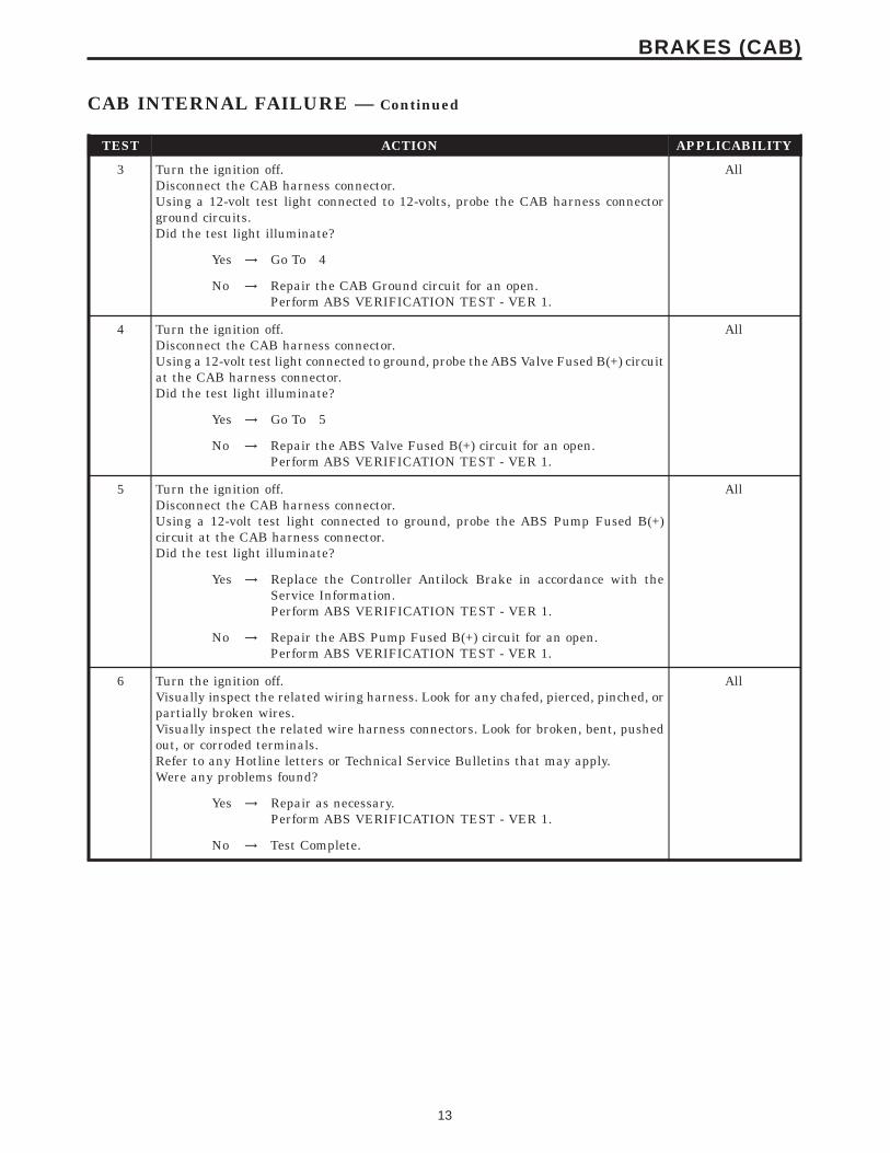
3 Turn the ignition off.Disconnect the CAB harness connector.Using a 12-volt test light connected to 12-volts, probe the CAB harness connectorground circuits.Did the test light illuminate?
All
Yes → Go To 4
No → Repair the CAB Ground circuit for an open.Perform ABS VERIFICATION TEST - VER 1.
4 Turn the ignition off.Disconnect the CAB harness connector.Using a 12-volt test light connected to ground, probe the ABS Valve Fused B(+) circuitat the CAB harness connector.Did the test light illuminate?
All
Yes → Go To 5
No → Repair the ABS Valve Fused B(+) circuit for an open.Perform ABS VERIFICATION TEST - VER 1.
5 Turn the ignition off.Disconnect the CAB harness connector.Using a 12-volt test light connected to ground, probe the ABS Pump Fused B(+)circuit at the CAB harness connector.Did the test light illuminate?
All
Yes → Replace the Controller Antilock Brake in accordance with theService Information.Perform ABS VERIFICATION TEST - VER 1.
No → Repair the ABS Pump Fused B(+) circuit for an open.Perform ABS VERIFICATION TEST - VER 1.
6 Turn the ignition off.Visually inspect the related wiring harness. Look for any chafed, pierced, pinched, orpartially broken wires.Visually inspect the related wire harness connectors. Look for broken, bent, pushedout, or corroded terminals.Refer to any Hotline letters or Technical Service Bulletins that may apply.Were any problems found?
All
Yes → Repair as necessary.Perform ABS VERIFICATION TEST - VER 1.
No → Test Complete.
13
BRAKES (CAB)
CAB INTERNAL FAILURE — Continued
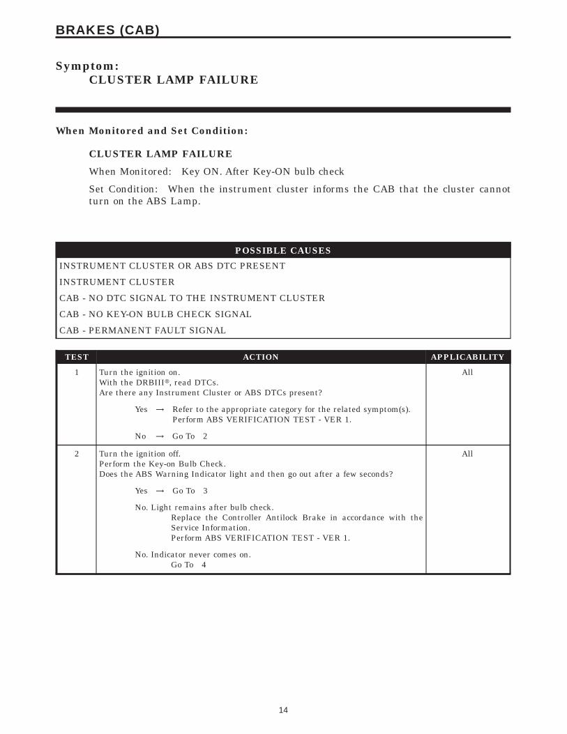
Symptom:CLUSTER LAMP FAILURE
When Monitored and Set Condition:
CLUSTER LAMP FAILURE
When Monitored: Key ON. After Key-ON bulb check
Set Condition: When the instrument cluster informs the CAB that the cluster cannotturn on the ABS Lamp.
POSSIBLE CAUSES
INSTRUMENT CLUSTER OR ABS DTC PRESENT
INSTRUMENT CLUSTER
CAB - NO DTC SIGNAL TO THE INSTRUMENT CLUSTER
CAB - NO KEY-ON BULB CHECK SIGNAL
CAB - PERMANENT FAULT SIGNAL
TEST ACTION APPLICABILITY
1 Turn the ignition on.With the DRBIIIt, read DTCs.Are there any Instrument Cluster or ABS DTCs present?
All
Yes → Refer to the appropriate category for the related symptom(s).Perform ABS VERIFICATION TEST - VER 1.
No → Go To 2
2 Turn the ignition off.Perform the Key-on Bulb Check.Does the ABS Warning Indicator light and then go out after a few seconds?
All
Yes → Go To 3
No. Light remains after bulb check.Replace the Controller Antilock Brake in accordance with theService Information.Perform ABS VERIFICATION TEST - VER 1.
No. Indicator never comes on.Go To 4
14
BRAKES (CAB)
TEST ACTION APPLICABILITY
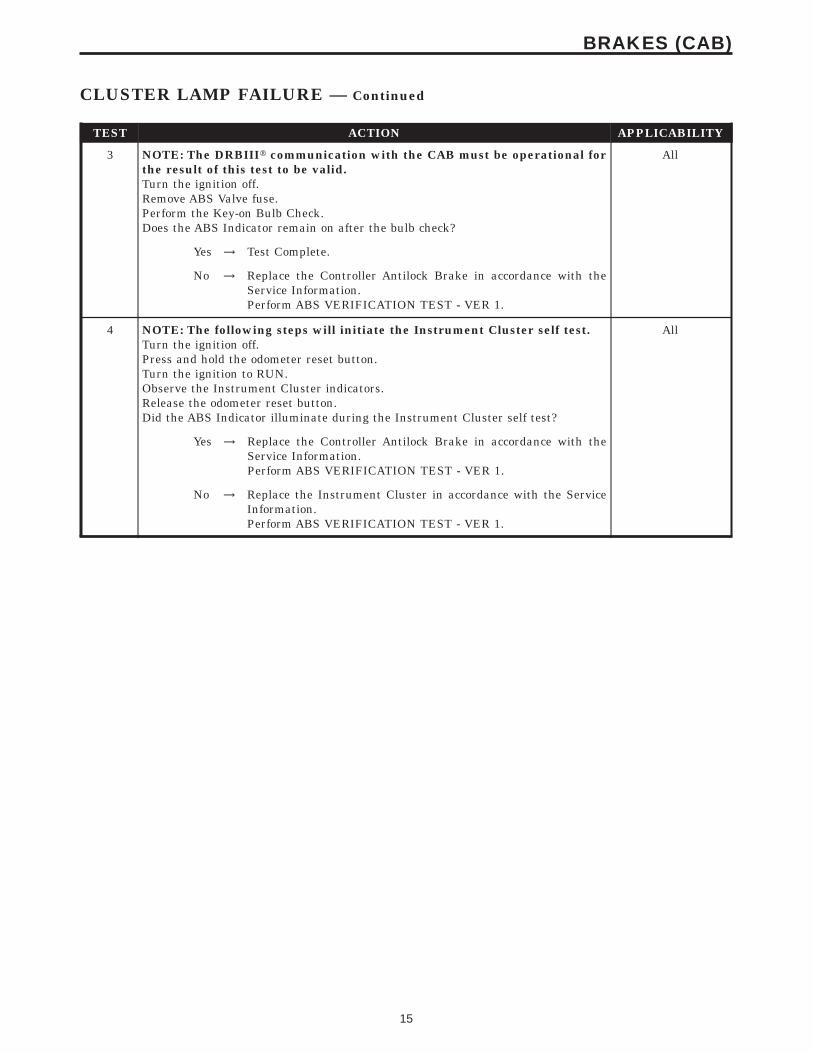
3 NOTE: The DRBIIIt communication with the CAB must be operational forthe result of this test to be valid.Turn the ignition off.Remove ABS Valve fuse.Perform the Key-on Bulb Check.Does the ABS Indicator remain on after the bulb check?
All
Yes → Test Complete.
No → Replace the Controller Antilock Brake in accordance with theService Information.Perform ABS VERIFICATION TEST - VER 1.
4 NOTE: The following steps will initiate the Instrument Cluster self test.Turn the ignition off.Press and hold the odometer reset button.Turn the ignition to RUN.Observe the Instrument Cluster indicators.Release the odometer reset button.Did the ABS Indicator illuminate during the Instrument Cluster self test?
All
Yes → Replace the Controller Antilock Brake in accordance with theService Information.Perform ABS VERIFICATION TEST - VER 1.
No → Replace the Instrument Cluster in accordance with the ServiceInformation.Perform ABS VERIFICATION TEST - VER 1.
15
BRAKES (CAB)
CLUSTER LAMP FAILURE — Continued
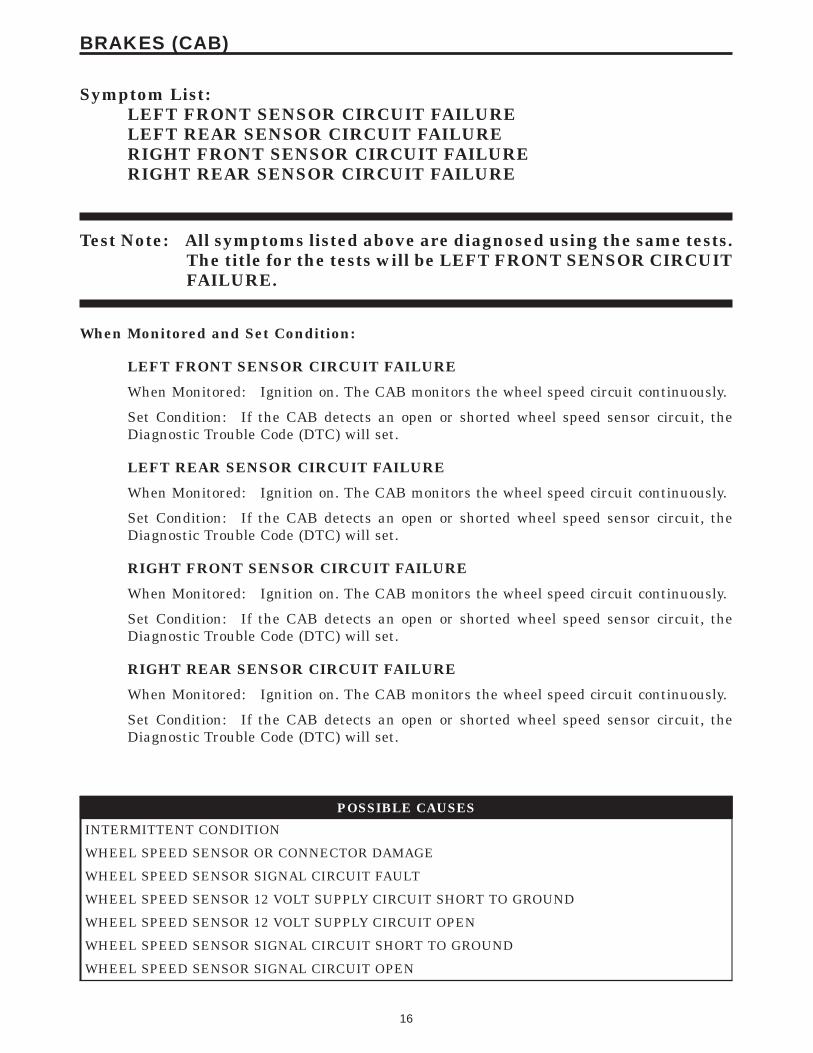
Symptom List:LEFT FRONT SENSOR CIRCUIT FAILURELEFT REAR SENSOR CIRCUIT FAILURERIGHT FRONT SENSOR CIRCUIT FAILURERIGHT REAR SENSOR CIRCUIT FAILURE
Test Note: All symptoms listed above are diagnosed using the same tests.The title for the tests will be LEFT FRONT SENSOR CIRCUITFAILURE.
When Monitored and Set Condition:
LEFT FRONT SENSOR CIRCUIT FAILURE
When Monitored: Ignition on. The CAB monitors the wheel speed circuit continuously.
Set Condition: If the CAB detects an open or shorted wheel speed sensor circuit, theDiagnostic Trouble Code (DTC) will set.
LEFT REAR SENSOR CIRCUIT FAILURE
When Monitored: Ignition on. The CAB monitors the wheel speed circuit continuously.
Set Condition: If the CAB detects an open or shorted wheel speed sensor circuit, theDiagnostic Trouble Code (DTC) will set.
RIGHT FRONT SENSOR CIRCUIT FAILURE
When Monitored: Ignition on. The CAB monitors the wheel speed circuit continuously.
Set Condition: If the CAB detects an open or shorted wheel speed sensor circuit, theDiagnostic Trouble Code (DTC) will set.
RIGHT REAR SENSOR CIRCUIT FAILURE
When Monitored: Ignition on. The CAB monitors the wheel speed circuit continuously.
Set Condition: If the CAB detects an open or shorted wheel speed sensor circuit, theDiagnostic Trouble Code (DTC) will set.
POSSIBLE CAUSES
INTERMITTENT CONDITION
WHEEL SPEED SENSOR OR CONNECTOR DAMAGE
WHEEL SPEED SENSOR SIGNAL CIRCUIT FAULT
WHEEL SPEED SENSOR 12 VOLT SUPPLY CIRCUIT SHORT TO GROUND
WHEEL SPEED SENSOR 12 VOLT SUPPLY CIRCUIT OPEN
WHEEL SPEED SENSOR SIGNAL CIRCUIT SHORT TO GROUND
WHEEL SPEED SENSOR SIGNAL CIRCUIT OPEN
16
BRAKES (CAB)

POSSIBLE CAUSES
CAB - 12 VOLT SUPPLY CIRCUIT FAULT
CAB - SIGNAL CIRCUIT FAULT
WHEEL SPEED SENSOR 12 VOLT SUPPLY SHORT TO GROUND
WHEEL SPEED SENSOR SIGNAL CIRCUIT INOPERATIVE
TEST ACTION APPLICABILITY
1 Turn the ignition on.With the DRBIIIt, read DTCs.With the DRBIIIt, read the Freeze Frame information.With the DRBIIIt, erase DTCs.Turn the ignition off.Turn the ignition on.With the DRBIIIt, read DTCs.NOTE: The CAB must sense all four wheels at 25km/h (15 mph) before it willextinguish the ABS indicators.Does the DRBIIIt display SENSOR CIRCUIT FAILURE?
All
Yes → Go To 2
No → Go To 13
2 Turn the ignition off.Inspect the CAB connector, affected Wheel Speed Sensor, and affected Wheel SpeedSensor connector.Is the affected Wheel Speed Sensor or any of the connectors damaged?
All
Yes → Repair as necessary.Perform ABS VERIFICATION TEST - VER 1.
No → Go To 3
3 Turn the ignition off.Disconnect the affected Wheel Speed Sensor connector.Note: Check connector - Clean/repair as necessary.Turn the ignition on.Measure the voltage between affected Wheel Speed Sensor 12 Volt Supply circuit andground.Is the voltage above 10 volts?
All
Yes → Go To 6
No → Go To 4
4 Turn the ignition off.Disconnect the CAB harness connector.Disconnect the affected Wheel Speed Sensor connector.Using a 12-volt test light connected to 12-volts, probe the affected Wheel SpeedSensor 12 Volt Supply circuit.Does the test light illuminate?
All
Yes → Repair the affected Wheel Speed Sensor 12 Volt Supply circuit fora short to ground.Perform ABS VERIFICATION TEST - VER 1.
No → Go To 5
17
BRAKES (CAB)
LEFT FRONT SENSOR CIRCUIT FAILURE — Continued

TEST ACTION APPLICABILITY
5 Turn the ignition off.Disconnect the CAB harness connector.Disconnect the affected Wheel Speed Sensor connector.Connect a jumper wire between affected Wheel Speed Sensor 12 Volt Supply circuitand ground.Using a 12-volt test light connected to 12-volts, probe the affected Wheel SpeedSensor 12 Volt Supply circuit.Does the test light illuminate?
All
Yes → Go To 6
No → Repair the affected Wheel Speed Sensor 12 Volt Supply circuit foran open.Perform ABS VERIFICATION TEST - VER 1.
6 Turn the ignition off.Disconnect the affected Wheel Speed Sensor connector.NOTE: Check connector - Clean/repair as necessary.Turn the ignition on.Measure the voltage between affected Wheel Speed Sensor Signal circuit and ground.Is the voltage above 1 volt?
All
Yes → Repair the affected Wheel Speed Sensor Signal circuit for a shortto voltage.Perform ABS VERIFICATION TEST - VER 1.
No → Go To 7
7 Turn the ignition off.Disconnect the CAB harness connector.Disconnect the affected Wheel Speed Sensor connector.Using a 12-volt test light connected to 12-volts, probe the affected Wheel SpeedSensor Signal circuit.Does the test light illuminate?
All
Yes → Repair the affected Wheel Speed Sensor Signal circuit for a shortto ground.Perform ABS VERIFICATION TEST - VER 1.
No → Go To 8
8 Turn the ignition off.Disconnect the CAB harness connector.Disconnect the affected Wheel Speed Sensor connector.Connect a jumper wire between affected Wheel Speed Sensor Signal circuit andground.Using a 12-volt test light connected to 12-volts, probe the affected Wheel SpeedSensor Signal circuit.Does the test light illuminate?
All
Yes → Go To 9
No → Repair the affected Wheel Speed Sensor Signal circuit for an open.Perform ABS VERIFICATION TEST - VER 1.
18
BRAKES (CAB)
LEFT FRONT SENSOR CIRCUIT FAILURE — Continued

TEST ACTION APPLICABILITY
9 Turn the ignition off.Remove the CAB harness strain relief to access wires.Reconnect the CAB harness connector.Turn the ignition on.Measure the voltage between affected Wheel Speed Sensor 12 Volt Supply circuit andground.Is the voltage above 10 volts?
All
Yes → Go To 10
No → Replace the Controller Antilock Brake in accordance with theService Information.Perform ABS VERIFICATION TEST - VER 1.
10 Turn the ignition off.Remove the CAB harness strain relief to access wires.Reconnect the CAB harness connector.Turn the ignition on.Measure the voltage between affected Wheel Speed Sensor 12 Volt Supply circuit andaffected Wheel Speed Sensor Signal circuit.Is the voltage above 10 volts?
All
Yes → Go To 11
No → Replace the Controller Antilock Brake in accordance with theService Information.Perform ABS VERIFICATION TEST - VER 1.
11 Turn the ignition off.Reconnect ALL affected Wheel Speed Sensor circuit connectors.Disconnect the affected Wheel Speed Sensor connector.Turn the ignition on.Measure the voltage of the affected Wheel Speed Sensor 12 Volt Supply circuit in theaffected Wheel Speed Sensor connector while reconnecting the sensor connector.Did the affected Wheel Speed Sensor 12 Volt Supply circuit drop voltage to 0 DCvolts?
All
Yes → Replace the affected Wheel Speed Sensor in accordance with theService Information.Perform ABS VERIFICATION TEST - VER 1.
No → Go To 12
12 Turn the ignition off.Reconnect ALL affected Wheel Speed Sensor circuit connectors.Turn the ignition on.Measure the DC voltage of the Wheel Speed Sensor Signal circuit in the affectedWheel Speed Sensor connector.Slowly rotate the wheel.Does the DC voltage toggle between 1.6 volts to .8 volts?
All
Yes → Go To 13
No → Replace the affected Wheel Speed Sensor in accordance with theService Information.Perform ABS VERIFICATION TEST - VER 1.
19
BRAKES (CAB)
LEFT FRONT SENSOR CIRCUIT FAILURE — Continued
TEST ACTION APPLICABILITY
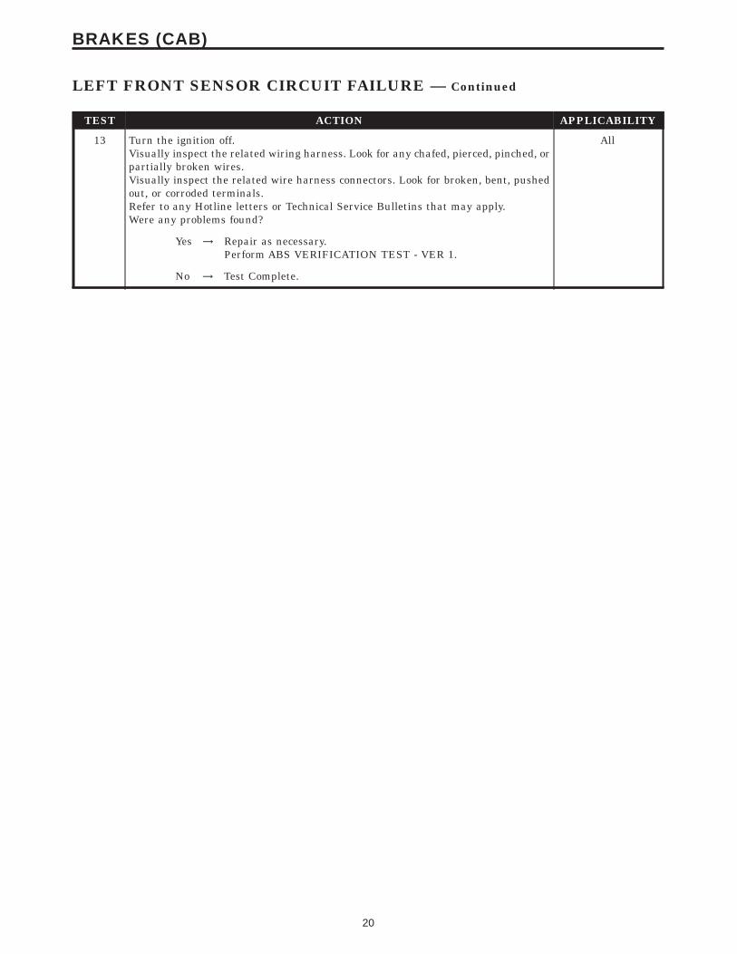
13 Turn the ignition off.Visually inspect the related wiring harness. Look for any chafed, pierced, pinched, orpartially broken wires.Visually inspect the related wire harness connectors. Look for broken, bent, pushedout, or corroded terminals.Refer to any Hotline letters or Technical Service Bulletins that may apply.Were any problems found?
All
Yes → Repair as necessary.Perform ABS VERIFICATION TEST - VER 1.
No → Test Complete.
20
BRAKES (CAB)
LEFT FRONT SENSOR CIRCUIT FAILURE — Continued

Symptom List:LEFT FRONT WHEEL SPEED SIGNAL FAILURELEFT REAR WHEEL SPEED SIGNAL FAILURERIGHT FRONT WHEEL SPEED SIGNAL FAILURERIGHT REAR WHEEL SPEED SIGNAL FAILURE
Test Note: All symptoms listed above are diagnosed using the same tests.The title for the tests will be LEFT FRONT WHEEL SPEEDSIGNAL FAILURE.
When Monitored and Set Condition:
LEFT FRONT WHEEL SPEED SIGNAL FAILURE
When Monitored: Wheel speed comparison is checked and verified at drive off andcontinuously thereafter.
Set Condition: If, during an ABS stop, the CAB commands any valve solenoid on for anextended length of time, and does not see a corresponding wheel speed change, theDiagnostic Trouble Code (DTC) is set. The DTC can also set if the signal is missing orerratic.
LEFT REAR WHEEL SPEED SIGNAL FAILURE
When Monitored: Wheel speed comparison is checked and verified at drive off andcontinuously thereafter.
Set Condition: If, during an ABS stop, the CAB commands any valve solenoid on for anextended length of time, and does not see a corresponding wheel speed change, theDiagnostic Trouble Code (DTC) is set. The DTC can also set if the signal is missing orerratic.
RIGHT FRONT WHEEL SPEED SIGNAL FAILURE
When Monitored: Wheel speed comparison is checked and verified at drive off andcontinuously thereafter.
Set Condition: If, during an ABS stop, the CAB commands any valve solenoid on for anextended length of time, and does not see a corresponding wheel speed change, theDiagnostic Trouble Code (DTC) is set. The DTC can also set if the signal is missing orerratic.
RIGHT REAR WHEEL SPEED SIGNAL FAILURE
When Monitored: Wheel speed comparison is checked and verified at drive off andcontinuously thereafter.
Set Condition: If, during an ABS stop, the CAB commands any valve solenoid on for anextended length of time, and does not see a corresponding wheel speed change, theDiagnostic Trouble Code (DTC) is set. The DTC can also set if the signal is missing orerratic.
21
BRAKES (CAB)

POSSIBLE CAUSES
WHEEL SPEED SIGNAL FAILURE DTC PRESENT
AFFECTED WHEEL SPEED SENSOR SIGNAL INOPERATIVE
AFFECTED WHEEL SPEED SENSOR CONNECTOR DAMAGED
AFFECTED WHEEL SPEED SENSOR TONE WHEEL DAMAGED
AFFECTED WHEEL SPEED SENSOR AIR GAP FAULT
WHEEL BEARING FAULT
BRAKE LINING FAULT
AFFECTED WHEEL SPEED SENSOR CIRCUIT ELECTRICAL FAULT
TEST ACTION APPLICABILITY
1 Turn the ignition on.With the DRBIIIt, read DTCs.With the DRBIIIt, read Freeze Frame information.NOTE: The CAB must sense ALL 4 wheels at 25 km/h (15 mph) before it willextinguish the ABS indicators.Does the DRBIIIt display WHEEL SPEED SIGNAL FAILURE and SENSORCIRCUIT FAILURE?
All
Yes → Refer to the affected Wheel Speed SENSOR CIRCUIT FAILUREfor the related symptom(s).Perform ABS VERIFICATION TEST - VER 1.
No → Go To 2
2 Turn the ignition on.With the DRBIIIt in Sensors, monitor ALL the Wheel Speed Sensor Signals while anassistant drives the vehicle.Slowly accelerate as straight as possible from a stop to 24 km/h (15 mph).Is the affected Wheel Speed Signal showing 0 km/h (0 mph)?
All
Yes → Go To 3
No → The condition is not present at this time. Monitor DRBIIItparameters while wiggling the related wiring harness. Refer toany Technical Service Bulletins(TSB) that may apply. Visuallyinspect the related wiring harness and connector terminals.Perform ABS VERIFICATION TEST - VER 1.
3 Turn the ignition off.Inspect the CAB connector, affected Wheel Speed Sensor, and affected Wheel SpeedSensor connector.Is the Wheel Speed Sensor or any connector damaged?
All
Yes → Repair as necessary.Perform ABS VERIFICATION TEST - VER 1.
No → Go To 4
22
BRAKES (CAB)
LEFT FRONT WHEEL SPEED SIGNAL FAILURE — Continued

TEST ACTION APPLICABILITY
4 Turn ignition off.Inspect the affected Tone Wheel for damaged, missing teeth, cracks, or looseness.NOTE: The Tone Wheel teeth should be perfectly square, not bent, or nicked.Is the affected Tone Wheel OK?
All
Yes → Go To 5
No → Replace the Tone Wheel in accordance with the Service Informa-tion.Perform ABS VERIFICATION TEST - VER 1.
5 Turn the ignition off.Using a Feeler Gauge, measure the affected Wheel Speed Sensor Air Gap.NOTE: Refer to the appropriate service information, if necessary, forprocedures or specifications.Is the Air Gap OK?
All
Yes → Go To 6
No → Repair as necessary.Perform ABS VERIFICATION TEST - VER 1.
6 Turn the ignition off.Inspect the wheel bearings for excessive runout or clearance.NOTE: Refer to the appropriate service information, if necessary, forprocedures or specifications.Is the bearing clearance OK ?
All
Yes → Go To 7
No → Repair as necessary.Perform ABS VERIFICATION TEST - VER 1.
7 Turn the ignition off.Visually inspect brakes for locking up due to lining contamination or overheating.Inspect all components for defects which may cause a Signal DTC to set.Is any component damaged?
All
Yes → Repair as necessary.Perform ABS VERIFICATION TEST - VER 1.
No → Refer to symptom SENSOR CIRCUIT FAILURE for furtherdiagnostics.Perform ABS VERIFICATION TEST - VER 1.
23
BRAKES (CAB)
LEFT FRONT WHEEL SPEED SIGNAL FAILURE — Continued

Symptom:PUMP CIRCUIT FAILURE
When Monitored and Set Condition:
PUMP CIRCUIT FAILURE
When Monitored: Ignition on. The CAB commands the pump on at 20 km/h (12 mph) tocheck its operation, if the brake switch is not applied. If the brake is applied, the test willrun at 40 km/h (25 mph).
Set Condition: The DTC is stored when the CAB detects: 1) Improper voltage decay afterthe pump was turned off. 2) Pump not energized by the CAB, but voltage is present for 3.5seconds. 3) Pump is turned on by the CAB, but without sufficient voltage to operate it.
POSSIBLE CAUSES
CAB - PUMP MOTOR RUNNING CONTINUOUSLY
ABS PUMP FUSE
ABS PUMP MOTOR INTERMITTENT DTC
DAMAGED CAB/CAB HARNESS CONNECTOR
ABS PUMP FUSED B(+) CIRCUIT INTERMITTENT SHORT TO GROUND
ABS PUMP FUSED B(+) CIRCUIT SHORT TO GROUND
CAB - INTERNAL FAULT
ABS PUMP MOTOR INOPERATIVE
ABS PUMP MOTOR OPEN
ABS PUMP MOTOR B(+) CIRCUIT OPEN
ABS PUMP MOTOR GROUND CIRCUIT OPEN
CAB - INTERNAL FAULT
TEST ACTION APPLICABILITY
1 Turn the ignition off.Turn the ignition on.Monitor the ABS Pump Motor for continuous operation.NOTE: The CAB must sense ALL wheels at 25 km/h (15 mph) before it willextinguish the ABS indicators.Is the ABS Pump Motor running continuously?
All
Yes → Replace the Controller Antilock Brake in accordance with theService Information.Perform ABS VERIFICATION TEST - VER 1.
No → Go To 2
24
BRAKES (CAB)

TEST ACTION APPLICABILITY
2 Turn the ignition off.Turn the ignition on.With the DRBIIIt, read DTCs.With the DRBIIIt, erase DTCs.Turn the ignition off.Turn the ignition on.With the DRBIIIt, actuate the ABS Pump Motor.Did the ABS Pump Motor operate?
All
Yes → Go To 3
No → Go To 4
3 Turn the ignition off.Visually inspect the related wiring harness. Look for any chafed, pierced, pinched, orpartially broken wires.Make sure the Pump Motor connecter is secure.Visually inspect the related wire harness connectors. Look for broken, bent, pushedout, or corroded terminals.Refer to any Hotline letters or Technical Service Bulletins that may apply.Were any problems found?
All
Yes → Repair as necessary.Perform ABS VERIFICATION TEST - VER 1.
No → Test Complete.
4 Turn the ignition off.Remove and inspect the ABS Pump fuse.Is the ABS Pump fuse open?
All
Yes → Go To 5
No → Go To 8
5 Turn the ignition off.Visually inspect the ABS Pump Fused B(+) circuit in the wiring harness.Look for any sign of an intermittent short to ground.Is the wiring harness OK?
All
Yes → Go To 6
No → Repair the ABS Pump Fused B(+) circuit for a short to ground.Perform ABS VERIFICATION TEST - VER 1.
6 Turn the ignition off.Disconnect the CAB harness connector.Check connectors - Clean/repair as necessary.Using a 12-volt test light connected to 12-volts, probe the ABS Pump Fused B(+)circuit fuse terminal.Does the test light illuminate?
All
Yes → Repair the ABS Pump Fused B(+) circuit for a short to ground.Perform ABS VERIFICATION TEST - VER 1.
No → Go To 7
25
BRAKES (CAB)
PUMP CIRCUIT FAILURE — Continued
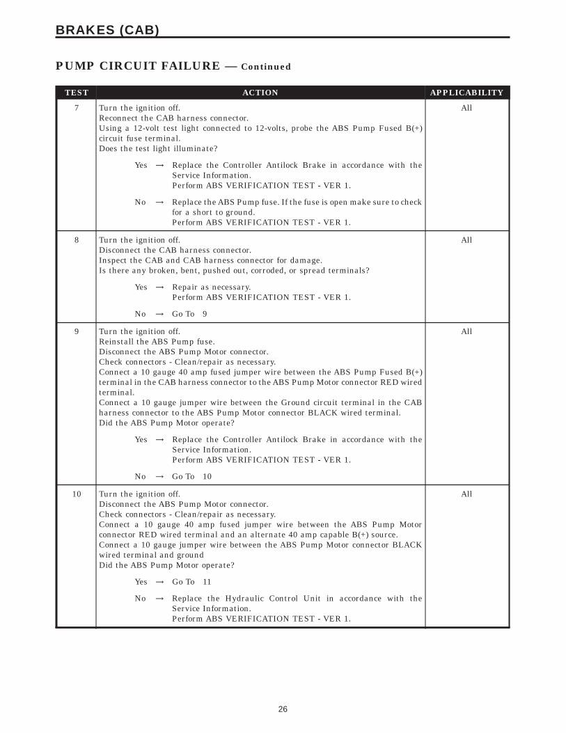
TEST ACTION APPLICABILITY
7 Turn the ignition off.Reconnect the CAB harness connector.Using a 12-volt test light connected to 12-volts, probe the ABS Pump Fused B(+)circuit fuse terminal.Does the test light illuminate?
All
Yes → Replace the Controller Antilock Brake in accordance with theService Information.Perform ABS VERIFICATION TEST - VER 1.
No → Replace the ABS Pump fuse. If the fuse is open make sure to checkfor a short to ground.Perform ABS VERIFICATION TEST - VER 1.
8 Turn the ignition off.Disconnect the CAB harness connector.Inspect the CAB and CAB harness connector for damage.Is there any broken, bent, pushed out, corroded, or spread terminals?
All
Yes → Repair as necessary.Perform ABS VERIFICATION TEST - VER 1.
No → Go To 9
9 Turn the ignition off.Reinstall the ABS Pump fuse.Disconnect the ABS Pump Motor connector.Check connectors - Clean/repair as necessary.Connect a 10 gauge 40 amp fused jumper wire between the ABS Pump Fused B(+)terminal in the CAB harness connector to the ABS Pump Motor connector RED wiredterminal.Connect a 10 gauge jumper wire between the Ground circuit terminal in the CABharness connector to the ABS Pump Motor connector BLACK wired terminal.Did the ABS Pump Motor operate?
All
Yes → Replace the Controller Antilock Brake in accordance with theService Information.Perform ABS VERIFICATION TEST - VER 1.
No → Go To 10
10 Turn the ignition off.Disconnect the ABS Pump Motor connector.Check connectors - Clean/repair as necessary.Connect a 10 gauge 40 amp fused jumper wire between the ABS Pump Motorconnector RED wired terminal and an alternate 40 amp capable B(+) source.Connect a 10 gauge jumper wire between the ABS Pump Motor connector BLACKwired terminal and groundDid the ABS Pump Motor operate?
All
Yes → Go To 11
No → Replace the Hydraulic Control Unit in accordance with theService Information.Perform ABS VERIFICATION TEST - VER 1.
26
BRAKES (CAB)
PUMP CIRCUIT FAILURE — Continued

TEST ACTION APPLICABILITY
11 Turn the ignition off.Disconnect the ABS Pump Motor connector.Check connectors - Clean/repair as necessary.Connect a 10 gauge 40 amp fused jumper wire between the ABS Pump Fused B(+)terminal in the CAB harness connector to the ABS Pump Motor connector RED wiredterminal.Connect a 10 gauge jumper wire between the ABS Pump Motor connector BLACKwired terminal and ground.Did the ABS Pump Motor operate?
All
Yes → Repair the ABS Pump Motor Fused B(+) circuit for an open.Perform ABS VERIFICATION TEST - VER 1.
No → Repair the ABS Pump Motor Ground circuit for an open.Perform ABS VERIFICATION TEST - VER 1.
27
BRAKES (CAB)
PUMP CIRCUIT FAILURE — Continued

Symptom:SYSTEM OVER VOLTAGE
When Monitored and Set Condition:
SYSTEM OVER VOLTAGE
When Monitored: Ignition on. The CAB monitors the Fused B(+) circuit at all times forproper system voltage.
Set Condition: If the voltage is above 16.5 volts, the Diagnostic Trouble Code (DTC) is set.
POSSIBLE CAUSES
INTERMITTENT DTC
BATTERY CHARGER CONNECTED
FUSED IGNITION SWITCH OUTPUT (RUN) CIRCUIT HIGH
DAMAGED CAB/CAB HARNESS CONNECTOR
CAB - GROUND CIRCUIT OPEN
CAB - INTERNAL FAULT
TEST ACTION APPLICABILITY
1 Turn the ignition on.With the DRBIIIt, read DTC’s.With the DRBIIIt, erase DTC’s.Turn the ignition off.Turn the ignition on.Start the engine.With the DRBIIIt, read DTC’s.Does the DRBIIIt display SYSTEM OVER VOLTAGE?
All
Yes → Go To 2
No → Go To 7
2 Is a battery charger connected to the vehicle? All
Yes → Ensure the battery is fully charged.Perform ABS VERIFICATION TEST - VER 1.
No → Go To 3
28
BRAKES (CAB)

TEST ACTION APPLICABILITY
3 Turn the ignition off.Disconnect the CAB connector.Note: Check connector - Clean/repair as necessary.Start the engine.Raise engine speed above 1,800 RPM’sMeasure the voltage between Fused Ignition Switch Output (RUN) circuit andground.Is the voltage above 16.5 volts ?
All
Yes → Refer to appropriate service information for Charging Systemtesting and repair.Perform ABS VERIFICATION TEST - VER 1.
No → Go To 4
4 Turn the ignition off.Disconnect the CAB connector.Note: Check connector - Clean/repair as necessary.Inspect the CAB and CAB harness connector for damage.Is there any broken, bent, pushed out, corroded, or spread terminals?
All
Yes → Repair as necessary.Perform ABS VERIFICATION TEST - VER 1.
No → Go To 5
5 Turn the ignition off.Disconnect the CAB connector.Note: Check connector - Clean/repair as necessary.Using a 12-volt test light connected to 12-volts, probe the Ground circuits.Does the test light illuminate?
All
Yes → Go To 6
No → Repair the Ground circuit for an open.Perform ABS VERIFICATION TEST - VER 1.
6 Turn the ignition off.Reconnect the CAB harness connector.Turn the ignition on.With the DRBIIIt in Sensors, read the ignition voltage.Does the DRBIIIt display ignition voltage above 16 volts?
All
Yes → Replace the Controller Antilock Brake in accordance with theService Information.Perform ABS VERIFICATION TEST - VER 1.
No → Go To 7
29
BRAKES (CAB)
SYSTEM OVER VOLTAGE — Continued
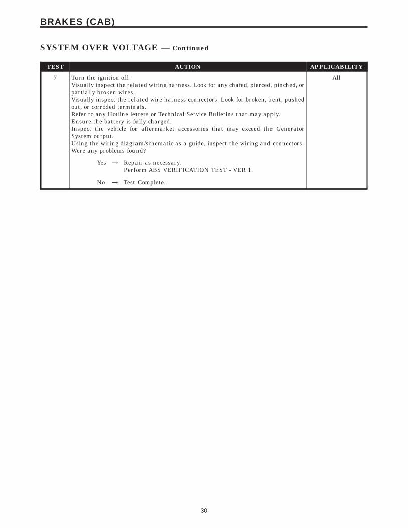
TEST ACTION APPLICABILITY
7 Turn the ignition off.Visually inspect the related wiring harness. Look for any chafed, pierced, pinched, orpartially broken wires.Visually inspect the related wire harness connectors. Look for broken, bent, pushedout, or corroded terminals.Refer to any Hotline letters or Technical Service Bulletins that may apply.Ensure the battery is fully charged.Inspect the vehicle for aftermarket accessories that may exceed the GeneratorSystem output.Using the wiring diagram/schematic as a guide, inspect the wiring and connectors.Were any problems found?
All
Yes → Repair as necessary.Perform ABS VERIFICATION TEST - VER 1.
No → Test Complete.
30
BRAKES (CAB)
SYSTEM OVER VOLTAGE — Continued

Symptom:SYSTEM UNDER VOLTAGE
When Monitored and Set Condition:
SYSTEM UNDER VOLTAGE
When Monitored: Ignition on. The CAB monitors the Fused Ignition Switch Outputcircuit voltage above 10 km/h (6 mph) for proper system voltage.
Set Condition: If the voltage is below 9.5 volts, the Diagnostic Trouble Code (DTC) is set.
POSSIBLE CAUSES
INTERMITTENT DTC
DAMAGED CAB/CAB HARNESS CONNECTOR
RUNNING BATTERY VOLTAGE LOW
CAB - GROUND CIRCUIT OPEN
FUSED IGNITION SWITCH OUTPUT (RUN) CIRCUIT OPEN
CAB - INTERNAL FAULT
TEST ACTION APPLICABILITY
1 Turn the ignition on.With the DRBIIIt, read DTC’s.With the DRBIIIt, erase DTC’s.Turn the ignition off.Turn the ignition on.Start the engine.Drive the vehicle above 16 km/h (10 mph) for at least 20 seconds.Stop the vehicleWith the DRBIIIt, read DTC’s.Does the DRBIIIt display SYSTEM UNDER VOLTAGE ?
All
Yes → Go To 2
No → Go To 6
2 Engine Running.Measure the battery voltage.Is the battery voltage below 10 volts?
All
Yes → Refer to appropriate service information for charging systemtesting and repair.Perform ABS VERIFICATION TEST - VER 1.
No → Go To 3
31
BRAKES (CAB)

TEST ACTION APPLICABILITY
3 Turn the ignition off.Disconnect the CAB harness connector.Inspect the CAB and CAB harness connector for damage.Is there any broken, bent, pushed out, corroded, or spread terminals?
All
Yes → Repair as necessary.Perform ABS VERIFICATION TEST - VER 1.
No → Go To 4
4 Turn the ignition off.Disconnect the CAB harness connector.Using a 12-volt test light connected to 12-volts, probe the Ground circuits.Does the test light illuminate?
All
Yes → Go To 5
No → Repair the Ground circuit for an open.Perform ABS VERIFICATION TEST - VER 1.
5 Turn the ignition on.Using a 12-volt test light connected to ground, probe the Fused Ignition SwitchOutput (RUN) circuit.Does the test light illuminate?
All
Yes → Replace the Controller Antilock Brake in accordance with theService Information.Perform ABS VERIFICATION TEST - VER 1.
No → Repair the Fused Ignition Switch Output (RUN) circuit for anopen.Perform ABS VERIFICATION TEST - VER 1.
6 Turn the ignition off.Visually inspect the related wiring harness. Look for any chafed, pierced, pinched, orpartially broken wires.Visually inspect the related wire harness connectors. Look for broken, bent, pushedout, or corroded terminals.Refer to any Hotline letters or Technical Service Bulletins that may apply.Ensure the battery is fully charged.Inspect the vehicle for aftermarket accessories that may exceed the GeneratorSystem output.Using the wiring diagram/schematic as a guide, inspect the wiring and connectors.Were any problems found?
All
Yes → Repair as necessary.Perform ABS VERIFICATION TEST - VER 1.
No → Test Complete.
32
BRAKES (CAB)
SYSTEM UNDER VOLTAGE — Continued

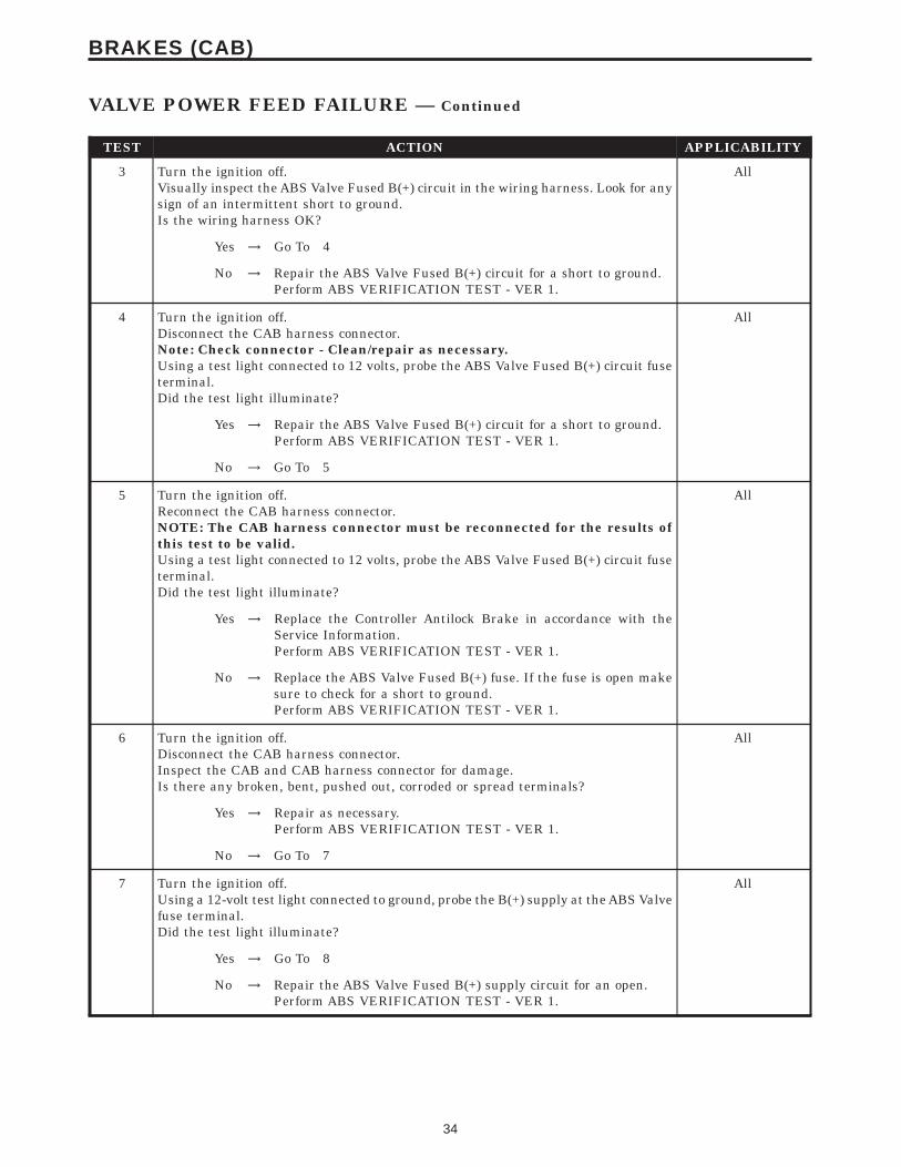
Symptom:VALVE POWER FEED FAILURE
When Monitored and Set Condition:
VALVE POWER FEED FAILURE
When Monitored: Ignition on. The CAB monitors its internal microprocessors for correctoperation.
Set Condition: If the CAB detects an internal fault, the DTC is set.
POSSIBLE CAUSES
INTERMITTENT DTC
ABS VALVE FUSE
ABS VALVE FUSED B(+) SUPPLY CIRCUIT OPEN
ABS VALVE FUSED B(+) CIRCUIT OPEN
ABS VALVE FUSED B(+) CIRCUIT INTERMITTENT SHORT TO GROUND
ABS VALVE FUSED B(+) CIRCUIT SHORT TO GROUND
DAMAGED CAB/CAB HARNESS CONNECTOR
CAB - GROUND CIRCUIT OPEN
CAB - INTERNAL FAULT
TEST ACTION APPLICABILITY
1 Turn the ignition on.With the DRBIIIt, read DTC’s.With the DRBIIIt, erase DTC’s.Turn the ignition off.Turn the ignition on.With the DRBIIIt, read DTC’s.Does the DRBIIIt display VALVE POWER FEED FAILURE?
All
Yes → Go To 2
No → Go To 10
2 Turn the ignition off.Remove and Inspect the ABS Valve fuse.Is the ABS Valve fuse open?
All
Yes → Go To 3
No → Go To 6
33
BRAKES (CAB)
TEST ACTION APPLICABILITY
3 Turn the ignition off.Visually inspect the ABS Valve Fused B(+) circuit in the wiring harness. Look for anysign of an intermittent short to ground.Is the wiring harness OK?
All
Yes → Go To 4
No → Repair the ABS Valve Fused B(+) circuit for a short to ground.Perform ABS VERIFICATION TEST - VER 1.
4 Turn the ignition off.Disconnect the CAB harness connector.Note: Check connector - Clean/repair as necessary.Using a test light connected to 12 volts, probe the ABS Valve Fused B(+) circuit fuseterminal.Did the test light illuminate?
All
Yes → Repair the ABS Valve Fused B(+) circuit for a short to ground.Perform ABS VERIFICATION TEST - VER 1.
No → Go To 5
5 Turn the ignition off.Reconnect the CAB harness connector.NOTE: The CAB harness connector must be reconnected for the results ofthis test to be valid.Using a test light connected to 12 volts, probe the ABS Valve Fused B(+) circuit fuseterminal.Did the test light illuminate?
All
Yes → Replace the Controller Antilock Brake in accordance with theService Information.Perform ABS VERIFICATION TEST - VER 1.
No → Replace the ABS Valve Fused B(+) fuse. If the fuse is open makesure to check for a short to ground.Perform ABS VERIFICATION TEST - VER 1.
6 Turn the ignition off.Disconnect the CAB harness connector.Inspect the CAB and CAB harness connector for damage.Is there any broken, bent, pushed out, corroded or spread terminals?
All
Yes → Repair as necessary.Perform ABS VERIFICATION TEST - VER 1.
No → Go To 7
7 Turn the ignition off.Using a 12-volt test light connected to ground, probe the B(+) supply at the ABS Valvefuse terminal.Did the test light illuminate?
All
Yes → Go To 8
No → Repair the ABS Valve Fused B(+) supply circuit for an open.Perform ABS VERIFICATION TEST - VER 1.
34
BRAKES (CAB)
VALVE POWER FEED FAILURE — Continued
TEST ACTION APPLICABILITY
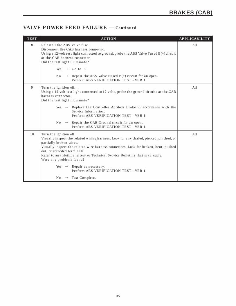
8 Reinstall the ABS Valve fuse.Disconnect the CAB harness connector.Using a 12-volt test light connected to ground, probe the ABS Valve Fused B(+) circuitat the CAB harness connector.Did the test light illuminate?
All
Yes → Go To 9
No → Repair the ABS Valve Fused B(+) circuit for an open.Perform ABS VERIFICATION TEST - VER 1.
9 Turn the ignition off.Using a 12-volt test light connected to 12-volts, probe the ground circuits at the CABharness connector.Did the test light illuminate?
All
Yes → Replace the Controller Antilock Brake in accordance with theService Information.Perform ABS VERIFICATION TEST - VER 1.
No → Repair the CAB Ground circuit for an open.Perform ABS VERIFICATION TEST - VER 1.
10 Turn the ignition off.Visually inspect the related wiring harness. Look for any chafed, pierced, pinched, orpartially broken wires.Visually inspect the related wire harness connectors. Look for broken, bent, pushedout, or corroded terminals.Refer to any Hotline letters or Technical Service Bulletins that may apply.Were any problems found?
All
Yes → Repair as necessary.Perform ABS VERIFICATION TEST - VER 1.
No → Test Complete.
35
BRAKES (CAB)
VALVE POWER FEED FAILURE — Continued

Symptom:*NO RESPONSE FROM CONTROLLER ANTILOCK BRAKE
POSSIBLE CAUSES
NO RESPONSE FROM CAB
GROUND CIRCUIT OPEN
OPEN FUSED IGNITION SWITCH OUTPUT CIRCUIT
OPEN PCI BUS CIRCUIT
CONTROLLER ANTILOCK BRAKE
TEST ACTION APPLICABILITY
1 Turn the ignition on.Note: As soon as one or more module communicates with the DRB, answerthe question.With the DRB, attempt to communicate with the Airbag Control Module (ACM).With the DRB, attempt to communicate with the Instrument Cluster (MIC).Was the DRB able to I/D or establish communications with either of the modules?
All
Yes → Go To 2
No → Refer to the Communications category and perform the symptomPCI Bus Communication Failure.Perform ABS VERIFICATION TEST - VER 1.
2 Turn the ignition off.Disconnect the CAB harness connector.Using a 12-volt test light connected to 12-volts, probe both ground circuits.Is the test light illuminated for both circuits?
All
Yes → Go To 3
No → Repair the ground circuit(s) for an open.Perform ABS VERIFICATION TEST - VER 1.
3 Turn the ignition off.Disconnect the CAB harness connector.Turn the ignition on.Using a 12-volt test light connected to ground, probe the Fused Ignition SwitchOutput circuit.Is the test light illuminated?
All
Yes → Go To 4
No → Repair the Fused Ignition Switch Output circuit for an open.Perform ABS VERIFICATION TEST - VER 1.
36
COMMUNICATION

TEST ACTION APPLICABILITY
4 Note: Ensure there is PCI Bus communication with other modules on thevehicle before proceeding. If not, refer to the symptom list from the menuand repair as necessary.Disconnect the CAB harness connector.Use Scope input cable CH7058, Cable to Probe adapter CH7062, and the red andblack test probes.Connect the scope input cable to the channel one connector on the DRB. Attach thered and black leads and the cable to probe adapter to the scope input cable.With the DRBIIIt select Pep Module Tools.Select lab scope.Select Live Data.Select 12 volt square wave.Press F2 for Scope.Press F2 and use the down arrow to set voltage range to 20 volts. Press F2 againwhen complete.Connect the Black lead to the chassis ground. Connect the Red lead to the PCI Buscircuit in the CAB connector.Turn the ignition on.Observe the voltage display on the DRB Lab Scope.Does the voltage pulse from 0 to approximately 7.5 volts?
All
Yes → Go To 5
No → Repair the PCI Bus circuit for an open.Perform ABS VERIFICATION TEST - VER 1.
5 If there are no possible causes remaining, view repair. All
RepairReplace the Controller Antilock Brake in accordance with theService Information.Perform ABS VERIFICATION TEST - VER 1.
37
COMMUNICATION
*NO RESPONSE FROM CONTROLLER ANTILOCK BRAKE — Continued

Verification Tests
ABS VERIFICATION TEST - VER 1 APPLICABILITY
1. Turn the ignition off.2. Connect all previously disconnected components and connectors.3. Ensure all accessories are turned off and the battery is fully charged.4. Ensure that the Ignition is on, and with the DRBIII, erase all Diagnostic Trouble Codes fromALL modules. Start the engine and allow it to run for 2 minutes and fully operate the systemthat was malfunctioning.5. Turn the ignition off and wait 5 seconds. Turn the ignition on and using the DRBIII, readDTC’s from ALL modules.6. If any Diagnostic Trouble Codes are present, return to Symptom list and troubleshoot newor recurring symptom.7. NOTE: For Sensor Signal and Pump Motor faults, the CAB must sense all 4 wheelsat 25 km/h (15 mph) before it will extinguish the ABS Indicator.8. If there are no DTC’s present after turning ignition on, road test the vehicle for at least 5minutes. Perform several antilock braking stops.9. Caution: Ensure braking capability is available before road testing.10. Again, with the DRBIIIt read DTC’s. If any DTC’s are present, return to Symptom list.11. If there are no Diagnostic Trouble Codes (DTC’s) present, and the customer’s concern can nolonger be duplicated, the repair is complete.Are any DTC’s present or is the original concern still present?
All
Yes → Repair is not complete, refer to appropriate symptom.
No → Repair is complete.
38
VERIFICATION TESTS

8.0 COMPONENT LOCATIONS
8.1 CONTROLLER ANTILOCK BRAKE
8.2 DATA LINK CONNECTOR
8.3 FUSES
COMPONENT
LOCATIONS
39
COMPONENT LOCATIONS

8.4 HYDRAULIC CONTROL UNIT
8.5 PUMP MOTOR
8.6 TONE WHEELSFRONT
COMPONENT
LOCATIONS
40
COMPONENT LOCATIONS

REAR
8.7 WHEEL SPEED SENSORSFRONT
REAR
COMPONENT
LOCATIONS
41
COMPONENT LOCATIONS

8.8 WHEEL SPEED SENSOR CONNECTORSFRONT
REAR
COMPONENT
LOCATIONS
42
COMPONENT LOCATIONS

9.0 CONNECTOR PINOUTS
ABS PUMP MOTOR - 2 WAYCAV CIRCUIT FUNCTION
1 TN GROUND
2 RD PUMP MOTOR RELAY OUTPUT
BRAKE LAMP SWITCH - BLACK 6 WAYCAV CIRCUIT FUNCTION
1 F32 18PK/DB FUSED B(+)
2 L50 18WT/TN BRAKE LAMP SWITCH OUTPUT
2 L50 18WT/TN BRAKE LAMP SWITCH OUTPUT
3 V30 20DB/RD (2.0L) SPEED CONTROL BRAKE LAMP SWITCH OUTPUT
4 V32 20YL/RD (2.0L) S/C SUPPLY
5 Z1 20BK (2.0L) GROUND
5 Z1 18BK (2.4L TURBO) GROUND
6 K29 20WT/PK BRAKE SWITCH SIGNAL
6 K29 20WT/PK (2.0L) BRAKE SWITCH SIGNAL
CONTROLLER ANTILOCK BRAKE - BLACK 24 WAYCAV CIRCUIT FUNCTION
1 Z1 12BK GROUND
2 B1 18YL/DB RIGHT REAR WHEEL SPEED SENSOR SIGNAL
3 B2 18YL RIGHT REAR WHEEL SPEED SENSOR 12 VOLT SUPPLY
4 - -
5 D25 18VT/YL PCI BUS
6 B6 18WT/DB RIGHT FRONT WHEEL SPEED SENSOR SIGNAL
7 B7 18WT RIGHT FRONT WHEEL SPEED SENSOR 12 VOLT SUPPLY
8 - -
9 A20 12RD/DB FUSED B(+)
10 F12 18DB/WT (2.0L) FUSED IGNITION SWITCH OUTPUT (RUN-START)
10 F12 18DB/RD (2.4LTURBO)
FUSED IGNITION SWITCH OUTPUT (RUN-START)
11 - -
12 - -
13 - -
14 - -
15 - -
16 Z1 12BK GROUND
17 - -
18 L50 18WT/TN BRAKE LAMP SWITCH OUTPUT
19 B3 18LG/DB LEFT REAR WHEEL SPEED SENSOR SIGNAL
20 B4 18LG LEFT REAR WHEEL SPEED SENSOR 12 VOLT SUPPLY
21 - -
22 B8 18RD/DB LEFT FRONT WHEEL SPEED SENSOR SIGNAL
23 B9 18RD LEFT FRONT WHEEL SPEED SENSOR 12 VOLT SUPPLY
24 A10 12RD/DG FUSED B(+)
CONNECTOR
PINOUTS
43
CONNECTOR PINOUTS

DATA LINK CONNECTOR - WHITE 16 WAYCAV CIRCUIT FUNCTION
1 - -
2 D25 20VT/YL PCI BUS (PCM)
3 - -
4 Z12 20BK/TN GROUND
5 Z12 20BK/TN GROUND
6 - -
7 D21 20PK SCI TRANSMIT (PCM)
8 - -
9 D6 20PK/LB (2.0L) SCI RECEIVE (TCM)
10 - -
11 - -
12 D20 20LG SCI RECEIVE (PCM)
13 - -
14 - -
15 D15 20WT/DG (2.0L) SCI TRANSMIT (TCM)
16 A14 18RD/WT FUSED B(+)
LEFT FRONT WHEEL SPEED SENSOR - BLACK 2 WAYCAV CIRCUIT FUNCTION
1 B9 18RD LEFT FRONT WHEEL SPEED SENSOR 12 VOLT SUPPLY
2 B8 18RD/DB LEFT FRONT WHEEL SPEED SENSOR SIGNAL
LEFT REAR WHEEL SPEED SENSOR - BLACK 2 WAYCAV CIRCUIT FUNCTION
1 B4 20LG LEFT REAR WHEEL SPEED SENSOR 12 VOLT SUPPLY
2 B3 20LG/DB LEFT REAR WHEEL SPEED SENSOR SIGNAL
RIGHT FRONT WHEEL SPEED SENSOR - BLACK 2 WAYCAV CIRCUIT FUNCTION
1 B7 18WT RIGHT FRONT WHEEL SPEED SENSOR 12 VOLT SUPPLY
2 B6 18WT/DB RIGHT FRONT WHEEL SPEED SENSOR SIGNAL
CONNECTOR
PINOUTS
44
CONNECTOR PINOUTS

RIGHT REAR WHEEL SPEED SENSOR - BLACK 2 WAYCAV CIRCUIT FUNCTION
1 B2 20YL RIGHT REAR WHEEL SPEED SENSOR 12 VOLT SUPPLY
2 B1 20YL/DB RIGHT REAR WHEEL SPEED SENSOR SIGNAL
CONNECTOR
PINOUTS
45
CONNECTOR PINOUTS

NOTES
46

10.0 SCHEMATIC DIAGRAMS
10.1 TEVES MARK 20e CONTROLLER ANTILOCK BRAKE – ABS
SCHEMATIC
DIAGRAMS
47
SCHEMATIC DIAGRAMS

NOTES
48

DIAGNOSTIC TEST PROCEDURES — TELL US!
DaimlerChrysler Corporation is constantly working to provide the technician the best diagnostic manuals possible.Your comments and recommendations regarding the diagnostic manuals and procedures are appreciated.
To best understand your suggestion, please complete the form giving us as much detail as possible.
Model Year Body Type Engine
Transmission Vehicle Mileage MDH
Diagnostic Procedure Book No. Page
Comments/recommendations (if necessary, draw sketch)
Name
Submitted by:
Address
City/State/Zip
Business Phone #
All comments become property of DaimlerChrysler Corporation and may be used without compensation.
Dealer Technical Operations800 Chrysler DriveCIMS 486-02-76Auburn Hills, MI 48326-2757