Documento Intel
595
Intel® Advanced Vector Extensions Programming Reference 319433-011 JUNE 2011
-
Upload
henrique-varella-ehrenfried -
Category
Documents
-
view
169 -
download
4
Transcript of Documento Intel

Intel® Advanced Vector ExtensionsProgramming Reference
319433-011
JUNE 2011

INFORMATION IN THIS DOCUMENT IS PROVIDED IN CONNECTION WITH INTEL PRODUCTS. NO LICENSE,EXPRESS OR IMPLIED, BY ESTOPPEL OR OTHERWISE, TO ANY INTELLECTUAL PROPERTY RIGHTS IS GRANT-ED BY THIS DOCUMENT. EXCEPT AS PROVIDED IN INTEL’S TERMS AND CONDITIONS OF SALE FOR SUCHPRODUCTS, INTEL ASSUMES NO LIABILITY WHATSOEVER, AND INTEL DISCLAIMS ANY EXPRESS OR IMPLIEDWARRANTY, RELATING TO SALE AND/OR USE OF INTEL PRODUCTS INCLUDING LIABILITY OR WARRANTIESRELATING TO FITNESS FOR A PARTICULAR PURPOSE, MERCHANTABILITY, OR INFRINGEMENT OF ANYPATENT, COPYRIGHT OR OTHER INTELLECTUAL PROPERTY RIGHT. INTEL PRODUCTS ARE NOT INTENDEDFOR USE IN MEDICAL, LIFE SAVING, OR LIFE SUSTAINING APPLICATIONS.
Intel may make changes to specifications and product descriptions at any time, without notice.
Developers must not rely on the absence or characteristics of any features or instructions marked “re-served” or “undefined.” Improper use of reserved or undefined features or instructions may cause unpre-dictable behavior or failure in developer's software code when running on an Intel processor. Intel reservesthese features or instructions for future definition and shall have no responsibility whatsoever for conflictsor incompatibilities arising from their unauthorized use.
The Intel® 64 architecture processors may contain design defects or errors known as errata. Current char-acterized errata are available on request.
Hyper-Threading Technology requires a computer system with an Intel® processor supporting Hyper-Threading Technology and an HT Technology enabled chipset, BIOS and operating system. Performance willvary depending on the specific hardware and software you use. For more information, see http://www.in-tel.com/technology/hyperthread/index.htm; including details on which processors support HT Technology.
Intel® Virtualization Technology requires a computer system with an enabled Intel® processor, BIOS, virtualmachine monitor (VMM) and for some uses, certain platform software enabled for it. Functionality, perfor-mance or other benefits will vary depending on hardware and software configurations. Intel® VirtualizationTechnology-enabled BIOS and VMM applications are currently in development.
64-bit computing on Intel architecture requires a computer system with a processor, chipset, BIOS, oper-ating system, device drivers and applications enabled for Intel® 64 architecture. Processors will not operate(including 32-bit operation) without an Intel® 64 architecture-enabled BIOS. Performance will vary depend-ing on your hardware and software configurations. Consult with your system vendor for more information.
Intel, Pentium, Intel Atom, Intel Xeon, Intel NetBurst, Intel Core, Intel Core Solo, Intel Core Duo, Intel Core2 Duo, Intel Core 2 Extreme, Intel Pentium D, Itanium, Intel SpeedStep, MMX, and VTune are trademarksor registered trademarks of Intel Corporation or its subsidiaries in the United States and other countries.
*Other names and brands may be claimed as the property of others.
Contact your local Intel sales office or your distributor to obtain the latest specifications and before placingyour product order.
Copies of documents which have an ordering number and are referenced in this document, or other Intelliterature, may be obtained from:
Intel CorporationP.O. Box 5937Denver, CO 80217-9808
or call 1-800-548-4725or visit Intel’s website at http://www.intel.com
Copyright © 1997-2011 Intel Corporation
ii Ref. # 319433-011

CONTENTSPAGE
CHAPTER 1INTEL® ADVANCED VECTOR EXTENSIONS1.1 About This Document . . . . . . . . . . . . . . . . . . . . . . . . . . . . . . . . . . . . . . . . . . . . . . . . . . . . . . . . . . . . . . 1-11.2 Overview . . . . . . . . . . . . . . . . . . . . . . . . . . . . . . . . . . . . . . . . . . . . . . . . . . . . . . . . . . . . . . . . . . . . . . . . . . 1-11.3 Intel® Advanced Vector Extensions Architecture Overview . . . . . . . . . . . . . . . . . . . . . . . . . . . 1-21.3.1 256-Bit Wide SIMD Register Support . . . . . . . . . . . . . . . . . . . . . . . . . . . . . . . . . . . . . . . . . . . . . 1-21.3.2 Instruction Syntax Enhancements . . . . . . . . . . . . . . . . . . . . . . . . . . . . . . . . . . . . . . . . . . . . . . . 1-31.3.3 VEX Prefix Instruction Encoding Support . . . . . . . . . . . . . . . . . . . . . . . . . . . . . . . . . . . . . . . . . 1-41.4 Overview AVX2. . . . . . . . . . . . . . . . . . . . . . . . . . . . . . . . . . . . . . . . . . . . . . . . . . . . . . . . . . . . . . . . . . . . 1-41.5 Functional Overview . . . . . . . . . . . . . . . . . . . . . . . . . . . . . . . . . . . . . . . . . . . . . . . . . . . . . . . . . . . . . . . 1-51.5.1 256-bit Floating-Point Arithmetic Processing Enhancements . . . . . . . . . . . . . . . . . . . . . . 1-51.5.2 256-bit Non-Arithmetic Instruction Enhancements. . . . . . . . . . . . . . . . . . . . . . . . . . . . . . . . 1-51.5.3 Arithmetic Primitives for 128-bit Vector and Scalar processing . . . . . . . . . . . . . . . . . . . . 1-61.5.4 Non-Arithmetic Primitives for 128-bit Vector and Scalar Processing . . . . . . . . . . . . . . . 1-61.5.5 AVX2 and 256-bit Vector Integer Processing . . . . . . . . . . . . . . . . . . . . . . . . . . . . . . . . . . . . . 1-71.6 General Purpose Instruction Set Enhancements. . . . . . . . . . . . . . . . . . . . . . . . . . . . . . . . . . . . . . 1-8
CHAPTER 2APPLICATION PROGRAMMING MODEL2.1 Detection of PCLMULQDQ and AES Instructions . . . . . . . . . . . . . . . . . . . . . . . . . . . . . . . . . . . . . . 2-12.2 Detection of AVX and FMA Instructions . . . . . . . . . . . . . . . . . . . . . . . . . . . . . . . . . . . . . . . . . . . . . 2-12.2.1 Detection of FMA . . . . . . . . . . . . . . . . . . . . . . . . . . . . . . . . . . . . . . . . . . . . . . . . . . . . . . . . . . . . . . . 2-32.2.2 Detection of VEX-Encoded AES and VPCLMULQDQ. . . . . . . . . . . . . . . . . . . . . . . . . . . . . . . . 2-42.2.3 Detection of AVX2 . . . . . . . . . . . . . . . . . . . . . . . . . . . . . . . . . . . . . . . . . . . . . . . . . . . . . . . . . . . . . . 2-62.2.4 Detection VEX-encoded GPR Instructions . . . . . . . . . . . . . . . . . . . . . . . . . . . . . . . . . . . . . . . . 2-72.3 Fused-Multiply-ADD (FMA) Numeric Behavior . . . . . . . . . . . . . . . . . . . . . . . . . . . . . . . . . . . . . . . . 2-72.3.1 FMA Instruction Operand Order and Arithmetic Behavior . . . . . . . . . . . . . . . . . . . . . . . . . 2-112.4 Accessing YMM Registers. . . . . . . . . . . . . . . . . . . . . . . . . . . . . . . . . . . . . . . . . . . . . . . . . . . . . . . . . . 2-122.5 Memory alignment . . . . . . . . . . . . . . . . . . . . . . . . . . . . . . . . . . . . . . . . . . . . . . . . . . . . . . . . . . . . . . . . 2-132.6 SIMD floating-point ExCeptions . . . . . . . . . . . . . . . . . . . . . . . . . . . . . . . . . . . . . . . . . . . . . . . . . . . . 2-152.7 Instruction Exception Specification. . . . . . . . . . . . . . . . . . . . . . . . . . . . . . . . . . . . . . . . . . . . . . . . . 2-152.7.1 Exceptions Type 1 (Aligned memory reference) . . . . . . . . . . . . . . . . . . . . . . . . . . . . . . . . . 2-212.7.2 Exceptions Type 2 (>=16 Byte Memory Reference, Unaligned) . . . . . . . . . . . . . . . . . . . 2-222.7.3 Exceptions Type 3 (<16 Byte memory argument). . . . . . . . . . . . . . . . . . . . . . . . . . . . . . . . 2-232.7.4 Exceptions Type 4 (>=16 Byte mem arg no alignment, no floating-point
exceptions) . . . . . . . . . . . . . . . . . . . . . . . . . . . . . . . . . . . . . . . . . . . . . . . . . . . . . . . . . . . . . . . . . . . . 2-242.7.5 Exceptions Type 5 (<16 Byte mem arg and no FP exceptions) . . . . . . . . . . . . . . . . . . . . 2-252.7.6 Exceptions Type 6 (VEX-Encoded Instructions Without Legacy SSE Analogues). . . . 2-262.7.7 Exceptions Type 7 (No FP exceptions, no memory arg). . . . . . . . . . . . . . . . . . . . . . . . . . . 2-272.7.8 Exceptions Type 8 (AVX and no memory argument) . . . . . . . . . . . . . . . . . . . . . . . . . . . . . 2-272.7.9 Exception Type 11 (VEX-only, mem arg no AC, floating-point exceptions) . . . . . . . . . 2-282.7.10 Exception Type 12 (VEX-only, VSIB mem arg, no AC, no floating-point exceptions). 2-292.7.11 Exception Conditions for VEX-Encoded GPR Instructions . . . . . . . . . . . . . . . . . . . . . . . . . 2-302.8 Programming Considerations with 128-bit SIMD Instructions . . . . . . . . . . . . . . . . . . . . . . . . 2-312.8.1 Clearing Upper YMM State Between AVX and Legacy SSE Instructions . . . . . . . . . . . . 2-32
i Ref. # 319433-011

2.8.2 Using AVX 128-bit Instructions Instead of Legacy SSE instructions . . . . . . . . . . . . . . . 2-332.8.3 Unaligned Memory Access and Buffer Size Management . . . . . . . . . . . . . . . . . . . . . . . . . 2-332.9 CPUID Instruction . . . . . . . . . . . . . . . . . . . . . . . . . . . . . . . . . . . . . . . . . . . . . . . . . . . . . . . . . . . . . . . . . 2-34
CPUID—CPU Identification . . . . . . . . . . . . . . . . . . . . . . . . . . . . . . . . . . . . . . . . . . . . . . . . . . . . . . 2-34
CHAPTER 3 SYSTEM PROGRAMMING MODEL3.1 YMM State, VEX Prefix and Supported Operating Modes . . . . . . . . . . . . . . . . . . . . . . . . . . . . . 3-13.2 YMM State Management . . . . . . . . . . . . . . . . . . . . . . . . . . . . . . . . . . . . . . . . . . . . . . . . . . . . . . . . . . . 3-23.2.1 Detection of YMM State Support . . . . . . . . . . . . . . . . . . . . . . . . . . . . . . . . . . . . . . . . . . . . . . . . . 3-23.2.2 Enabling of YMM State . . . . . . . . . . . . . . . . . . . . . . . . . . . . . . . . . . . . . . . . . . . . . . . . . . . . . . . . . . 3-23.2.3 Enabling of SIMD Floating-Exception Support . . . . . . . . . . . . . . . . . . . . . . . . . . . . . . . . . . . . . 3-33.2.4 The Layout of XSAVE Area . . . . . . . . . . . . . . . . . . . . . . . . . . . . . . . . . . . . . . . . . . . . . . . . . . . . . . 3-43.2.5 XSAVE/XRSTOR Interaction with YMM State and MXCSR. . . . . . . . . . . . . . . . . . . . . . . . . . 3-53.2.6 Processor Extended State Save Optimization and XSAVEOPT . . . . . . . . . . . . . . . . . . . . . 3-73.2.6.1 XSAVEOPT Usage Guidelines . . . . . . . . . . . . . . . . . . . . . . . . . . . . . . . . . . . . . . . . . . . . . . . . . 3-83.3 Reset Behavior . . . . . . . . . . . . . . . . . . . . . . . . . . . . . . . . . . . . . . . . . . . . . . . . . . . . . . . . . . . . . . . . . . . . 3-93.4 Emulation. . . . . . . . . . . . . . . . . . . . . . . . . . . . . . . . . . . . . . . . . . . . . . . . . . . . . . . . . . . . . . . . . . . . . . . . . . 3-93.5 Writing AVX floating-point exception handlers. . . . . . . . . . . . . . . . . . . . . . . . . . . . . . . . . . . . . . . 3-9
CHAPTER 4INSTRUCTION FORMAT4.1 Instruction Formats . . . . . . . . . . . . . . . . . . . . . . . . . . . . . . . . . . . . . . . . . . . . . . . . . . . . . . . . . . . . . . . . 4-14.1.1 VEX and the LOCK prefix . . . . . . . . . . . . . . . . . . . . . . . . . . . . . . . . . . . . . . . . . . . . . . . . . . . . . . . . 4-24.1.2 VEX and the 66H, F2H, and F3H prefixes. . . . . . . . . . . . . . . . . . . . . . . . . . . . . . . . . . . . . . . . . 4-24.1.3 VEX and the REX prefix . . . . . . . . . . . . . . . . . . . . . . . . . . . . . . . . . . . . . . . . . . . . . . . . . . . . . . . . . 4-24.1.4 The VEX Prefix . . . . . . . . . . . . . . . . . . . . . . . . . . . . . . . . . . . . . . . . . . . . . . . . . . . . . . . . . . . . . . . . . 4-24.1.4.1 VEX Byte 0, bits[7:0] . . . . . . . . . . . . . . . . . . . . . . . . . . . . . . . . . . . . . . . . . . . . . . . . . . . . . . . . . 4-44.1.4.2 VEX Byte 1, bit [7] - ‘R’ . . . . . . . . . . . . . . . . . . . . . . . . . . . . . . . . . . . . . . . . . . . . . . . . . . . . . . . 4-44.1.4.3 3-byte VEX byte 1, bit[6] - ‘X’. . . . . . . . . . . . . . . . . . . . . . . . . . . . . . . . . . . . . . . . . . . . . . . . . 4-44.1.4.4 3-byte VEX byte 1, bit[5] - ‘B’. . . . . . . . . . . . . . . . . . . . . . . . . . . . . . . . . . . . . . . . . . . . . . . . . 4-64.1.4.5 3-byte VEX byte 2, bit[7] - ‘W’ . . . . . . . . . . . . . . . . . . . . . . . . . . . . . . . . . . . . . . . . . . . . . . . . 4-64.1.4.6 2-byte VEX Byte 1, bits[6:3] and 3-byte VEX Byte 2, bits [6:3]- ‘vvvv’ the Source
or dest Register Specifier . . . . . . . . . . . . . . . . . . . . . . . . . . . . . . . . . . . . . . . . . . . . . . . . . . . . 4-64.1.5 Instruction Operand Encoding and VEX.vvvv, ModR/M. . . . . . . . . . . . . . . . . . . . . . . . . . . . . 4-74.1.5.1 3-byte VEX byte 1, bits[4:0] - “m-mmmm” . . . . . . . . . . . . . . . . . . . . . . . . . . . . . . . . . . . . . 4-94.1.5.2 2-byte VEX byte 1, bit[2], and 3-byte VEX byte 2, bit [2]- “L”. . . . . . . . . . . . . . . . . . . 4-94.1.5.3 2-byte VEX byte 1, bits[1:0], and 3-byte VEX byte 2, bits [1:0]- “pp” . . . . . . . . . . . . 4-94.1.6 The Opcode Byte . . . . . . . . . . . . . . . . . . . . . . . . . . . . . . . . . . . . . . . . . . . . . . . . . . . . . . . . . . . . . . 4-104.1.7 The MODRM, SIB, and Displacement Bytes . . . . . . . . . . . . . . . . . . . . . . . . . . . . . . . . . . . . . . . 4-104.1.8 The Third Source Operand (Immediate Byte). . . . . . . . . . . . . . . . . . . . . . . . . . . . . . . . . . . . . 4-104.1.9 AVX Instructions and the Upper 128-bits of YMM registers . . . . . . . . . . . . . . . . . . . . . . 4-104.1.9.1 Vector Length Transition and Programming Considerations . . . . . . . . . . . . . . . . . . . 4-104.1.10 AVX Instruction Length . . . . . . . . . . . . . . . . . . . . . . . . . . . . . . . . . . . . . . . . . . . . . . . . . . . . . . . . 4-114.2 Vector SIB (VSIB) Memory Addressing . . . . . . . . . . . . . . . . . . . . . . . . . . . . . . . . . . . . . . . . . . . . . . 4-114.2.1 64-bit Mode VSIB Memory Addressing . . . . . . . . . . . . . . . . . . . . . . . . . . . . . . . . . . . . . . . . . . 4-134.3 VEX Encoding Support for GPR Instructions . . . . . . . . . . . . . . . . . . . . . . . . . . . . . . . . . . . . . . . . 4-13
ii Ref. # 319433-011

CHAPTER 5 INSTRUCTION SET REFERENCE5.1 Interpreting InstructIon Reference Pages . . . . . . . . . . . . . . . . . . . . . . . . . . . . . . . . . . . . . . . . . . . 5-15.1.1 Instruction Format. . . . . . . . . . . . . . . . . . . . . . . . . . . . . . . . . . . . . . . . . . . . . . . . . . . . . . . . . . . . . . . 5-1
(V)ADDSD- ADD Scalar Double-Precision Floating-Point Values (THIS IS AN EXAMPLE). . . . . . . . . . . . . . . . . . . . . . . . . . . . . . . . . . . . . . . . . . . . . . . . . . . . . . . . . . . . . . . . . . . . . . . 5-2
5.1.2 Opcode Column in the Instruction Summary Table . . . . . . . . . . . . . . . . . . . . . . . . . . . . . . . . . 5-25.1.3 Instruction Column in the Instruction Summary Table . . . . . . . . . . . . . . . . . . . . . . . . . . . . . . 5-55.1.4 Operand Encoding column in the Instruction Summary Table . . . . . . . . . . . . . . . . . . . . . . . 5-65.1.5 64/32 bit Mode Support column in the Instruction Summary Table . . . . . . . . . . . . . . . . . 5-65.1.6 CPUID Support column in the Instruction Summary Table . . . . . . . . . . . . . . . . . . . . . . . . . . 5-65.2 Summary of Terms . . . . . . . . . . . . . . . . . . . . . . . . . . . . . . . . . . . . . . . . . . . . . . . . . . . . . . . . . . . . . . . . 5-75.3 Instruction SET Reference . . . . . . . . . . . . . . . . . . . . . . . . . . . . . . . . . . . . . . . . . . . . . . . . . . . . . . . . . 5-7
MPSADBW - Multiple Sum of Absolute Differences. . . . . . . . . . . . . . . . . . . . . . . . . . . . . . . . . 5-8PABSB/PABSW/PABSD — Packed Absolute Value . . . . . . . . . . . . . . . . . . . . . . . . . . . . . . . .5-17PACKSSWB/PACKSSDW—Pack with Signed Saturation . . . . . . . . . . . . . . . . . . . . . . . . . . .5-21PACKUSDW — Pack with Unsigned Saturation . . . . . . . . . . . . . . . . . . . . . . . . . . . . . . . . . . .5-26PACKUSWB — Pack with Unsigned Saturation . . . . . . . . . . . . . . . . . . . . . . . . . . . . . . . . . . .5-30PADDB/PADDW/PADDD/PADDQ — Add Packed Integers . . . . . . . . . . . . . . . . . . . . . . . . . .5-34PADDSB/PADDSW — Add Packed Signed Integers with Signed Saturation . . . . . . . . .5-39PADDUSB/PADDUSW — Add Packed Unsigned Integers with Unsigned Saturation. .5-42PALIGNR - Byte Align . . . . . . . . . . . . . . . . . . . . . . . . . . . . . . . . . . . . . . . . . . . . . . . . . . . . . . . . . . .5-45PAND — Logical AND . . . . . . . . . . . . . . . . . . . . . . . . . . . . . . . . . . . . . . . . . . . . . . . . . . . . . . . . . . .5-48PANDN — Logical AND NOT . . . . . . . . . . . . . . . . . . . . . . . . . . . . . . . . . . . . . . . . . . . . . . . . . . . . .5-50PAVGB/PAVGW — Average Packed Integers . . . . . . . . . . . . . . . . . . . . . . . . . . . . . . . . . . . . .5-52PBLENDVB — Variable Blend Packed Bytes . . . . . . . . . . . . . . . . . . . . . . . . . . . . . . . . . . . . . .5-55PBLENDW - Blend Packed Words . . . . . . . . . . . . . . . . . . . . . . . . . . . . . . . . . . . . . . . . . . . . . . . .5-60PCMPEQB/PCMPEQW/PCMPEQD/PCMPEQQ- Compare Packed Integers for Equality . . . . . . . . . . . . . . . . . . . . . . . . . . . . . . . . . . . . . . . . . . . . . . . . . . . . . . . . . . . . . . . . . . . . . . . .5-63PCMPGTB/PCMPGTW/PCMPGTD/PCMPGTQ- Compare Packed Integers for Greater Than. . . . . . . . . . . . . . . . . . . . . . . . . . . . . . . . . . . . . . . . . . . . . . . . . . . . . . . . . . . . . . . . . . . . . . . . . . .5-68PHADDW/PHADDD - Packed Horizontal Add . . . . . . . . . . . . . . . . . . . . . . . . . . . . . . . . . . . . . .5-73PHADDSW - Packed Horizontal Add with Saturation . . . . . . . . . . . . . . . . . . . . . . . . . . . . . .5-77PHSUBW/PHSUBD - Packed Horizontal Subtract . . . . . . . . . . . . . . . . . . . . . . . . . . . . . . . . . .5-80PHSUBSW - Packed Horizontal Subtract with Saturation . . . . . . . . . . . . . . . . . . . . . . . . . .5-84PMADDUBSW- Multiply and Add Packed Integers . . . . . . . . . . . . . . . . . . . . . . . . . . . . . . . . .5-87PMADDWD- Multiply and Add Packed Integers. . . . . . . . . . . . . . . . . . . . . . . . . . . . . . . . . . . .5-89PMAXSB/PMAXSW/PMAXSD- Maximum of Packed Signed Integers . . . . . . . . . . . . . . . .5-92PMAXUB/PMAXUW/PMAXUD- Maximum of Packed Unsigned Integers . . . . . . . . . . . . .5-97PMINSB/PMINSW/PMINSD- Minimum of Packed Signed Integers . . . . . . . . . . . . . . . . . 5-102PMINUB/PMINUW/PMINUD- Minimum of Packed Unsigned Integers . . . . . . . . . . . . . . 5-107PMOVMSKB- Move Byte Mask . . . . . . . . . . . . . . . . . . . . . . . . . . . . . . . . . . . . . . . . . . . . . . . . . 5-112PMOVSX - Packed Move with Sign Extend . . . . . . . . . . . . . . . . . . . . . . . . . . . . . . . . . . . . . 5-114PMOVZX - Packed Move with Zero Extend . . . . . . . . . . . . . . . . . . . . . . . . . . . . . . . . . . . . 5-120PMULDQ - Multiply Packed Doubleword Integers . . . . . . . . . . . . . . . . . . . . . . . . . . . . . . . 5-126PMULHRSW - Multiply Packed Unsigned Integers with Round and Scale. . . . . . . . . . 5-129PMULHUW - Multiply Packed Unsigned Integers and Store High Result. . . . . . . . . . . 5-132
Ref. # 319433-011 iii

PMULHW - Multiply Packed Integers and Store High Result . . . . . . . . . . . . . . . . . . . . . .5-135PMULLW/PMULLD - Multiply Packed Integers and Store Low Result . . . . . . . . . . . . . .5-138PMULUDQ - Multiply Packed Unsigned Doubleword Integers . . . . . . . . . . . . . . . . . . . . .5-143POR - Bitwise Logical Or . . . . . . . . . . . . . . . . . . . . . . . . . . . . . . . . . . . . . . . . . . . . . . . . . . . . . . .5-146PSADBW - Compute Sum of Absolute Differences. . . . . . . . . . . . . . . . . . . . . . . . . . . . . . .5-148PSHUFB - Packed Shuffle Bytes. . . . . . . . . . . . . . . . . . . . . . . . . . . . . . . . . . . . . . . . . . . . . . . .5-151PSHUFD - Shuffle Packed Doublewords . . . . . . . . . . . . . . . . . . . . . . . . . . . . . . . . . . . . . . . .5-154PSHUFHW — Shuffle Packed High Words . . . . . . . . . . . . . . . . . . . . . . . . . . . . . . . . . . . . . . .5-157PSHUFLW - Shuffle Packed Low Words . . . . . . . . . . . . . . . . . . . . . . . . . . . . . . . . . . . . . . . . .5-160PSIGNB/PSIGNW/PSIGND - Packed SIGN . . . . . . . . . . . . . . . . . . . . . . . . . . . . . . . . . . . . . . . .5-163PSLLDQ - Byte Shift Left . . . . . . . . . . . . . . . . . . . . . . . . . . . . . . . . . . . . . . . . . . . . . . . . . . . . . .5-169PSLLW/PSLLD/PSLLQ - Bit Shift Left . . . . . . . . . . . . . . . . . . . . . . . . . . . . . . . . . . . . . . . . . .5-171PSRAW/PSRAD - Bit Shift Arithmetic Right . . . . . . . . . . . . . . . . . . . . . . . . . . . . . . . . . . . . .5-178PSRLDQ - Byte Shift Right . . . . . . . . . . . . . . . . . . . . . . . . . . . . . . . . . . . . . . . . . . . . . . . . . . . . .5-183PSRLW/PSRLD/PSRLQ - Shift Packed Data Right Logical . . . . . . . . . . . . . . . . . . . . . . . . .5-185PSUBB/PSUBW/PSUBD/PSUBQ -Packed Integer Subtract . . . . . . . . . . . . . . . . . . . . . . . .5-192PSUBSB/PSUBSW -Subtract Packed Signed Integers with Signed Saturation. . . . . .5-198PSUBUSB/PSUBUSW -Subtract Packed Unsigned Integers with Unsigned Saturation . . . . . . . . . . . . . . . . . . . . . . . . . . . . . . . . . . . . . . . . . . . . . . . . . . . . . . . . . . . . . . . . . . . .5-201PUNPCKHBW/PUNPCKHWD/PUNPCKHDQ/PUNPCKHQDQ - Unpack High Data . . . . .5-204PUNPCKLBW/PUNPCKLWD/PUNPCKLDQ/PUNPCKLQDQ - Unpack Low Data . . . . . .5-211PXOR - Exclusive Or . . . . . . . . . . . . . . . . . . . . . . . . . . . . . . . . . . . . . . . . . . . . . . . . . . . . . . . . . . .5-218MOVNTDQA- Load Double Quadword Non-Temporal Aligned Hint . . . . . . . . . . . . . . . .5-220VBROADCAST- Broadcast Floating-Point Data . . . . . . . . . . . . . . . . . . . . . . . . . . . . . . . . . .5-223VBROADCASTF128/I128- Broadcast 128-Bit Data . . . . . . . . . . . . . . . . . . . . . . . . . . . . . .5-225VPBLENDD - Blend Packed Dwords. . . . . . . . . . . . . . . . . . . . . . . . . . . . . . . . . . . . . . . . . . . . .5-227VPBROADCAST- Broadcast Integer Data . . . . . . . . . . . . . . . . . . . . . . . . . . . . . . . . . . . . . . .5-229VPERMD - Full Doublewords Element Permutation . . . . . . . . . . . . . . . . . . . . . . . . . . . . . .5-234VPERMPD - Permute Double-Precision Floating-Point Elements . . . . . . . . . . . . . . . . . .5-236VPERMPS - Permute Single-Precision Floating-Point Elements . . . . . . . . . . . . . . . . . . .5-237VPERMQ - Qwords Element Permutation . . . . . . . . . . . . . . . . . . . . . . . . . . . . . . . . . . . . . . .5-239VPERM2I128- Permute Integer Values . . . . . . . . . . . . . . . . . . . . . . . . . . . . . . . . . . . . . . . . .5-240VEXTRACTI128- Extract packed Integer Values . . . . . . . . . . . . . . . . . . . . . . . . . . . . . . . .5-242VINSERTI128- Insert packed Integer values . . . . . . . . . . . . . . . . . . . . . . . . . . . . . . . . . . . .5-244VPMASKMOV- Conditional SIMD Integer Packed Loads and Stores . . . . . . . . . . . . . . .5-246VPSLLVD/VPSLLVQ - Variable Bit Shift Left Logical . . . . . . . . . . . . . . . . . . . . . . . . . . . . .5-250VPSRAVD - Variable Bit Shift Right Arithmetic . . . . . . . . . . . . . . . . . . . . . . . . . . . . . . . . . .5-253VPSRLVD/VPSRLVQ - Variable Bit Shift Right Logical . . . . . . . . . . . . . . . . . . . . . . . . . . .5-255VGATHERDPD/VGATHERQPD - Gather Packed DP FP values Using Signed Dword/Qword Indices . . . . . . . . . . . . . . . . . . . . . . . . . . . . . . . . . . . . . . . . . . . . . . . . . . . . . . . . .5-258VGATHERDPS/VGATHERQPS - Gather Packed SP FP values Using Signed Dword/Qword Indices . . . . . . . . . . . . . . . . . . . . . . . . . . . . . . . . . . . . . . . . . . . . . . . . . . . . . . . . .5-264VPGATHERDD/VPGATHERQD - Gather Packed Dword values Using Signed Dword/Qword Indices . . . . . . . . . . . . . . . . . . . . . . . . . . . . . . . . . . . . . . . . . . . . . . . . . . . . . . . . .5-270VPGATHERDQ/VPGATHERQQ - Gather Packed Qword values Using Signed Dword/Qword Indices . . . . . . . . . . . . . . . . . . . . . . . . . . . . . . . . . . . . . . . . . . . . . . . . . . . . . . . . .5-276
iv Ref. # 319433-011

CHAPTER 6 INSTRUCTION SET REFERENCE - FMA6.1 FMA InstructIon SET Reference . . . . . . . . . . . . . . . . . . . . . . . . . . . . . . . . . . . . . . . . . . . . . . . . . . . . 6-1
VFMADD132PD/VFMADD213PD/VFMADD231PD - Fused Multiply-Add of Packed Double-Precision Floating-Point Values . . . . . . . . . . . . . . . . . . . . . . . . . . . . . . . . . . . . . . . . . . . 6-2VFMADD132PS/VFMADD213PS/VFMADD231PS - Fused Multiply-Add of Packed Single-Precision Floating-Point Values . . . . . . . . . . . . . . . . . . . . . . . . . . . . . . . . . . . . . . . . . . . . 6-6VFMADD132SD/VFMADD213SD/VFMADD231SD - Fused Multiply-Add of Scalar Double-Precision Floating-Point Values . . . . . . . . . . . . . . . . . . . . . . . . . . . . . . . . . . . . . . . . . .6-10VFMADD132SS/VFMADD213SS/VFMADD231SS - Fused Multiply-Add of Scalar Single-Precision Floating-Point Values . . . . . . . . . . . . . . . . . . . . . . . . . . . . . . . . . . . . . . . . . . .6-13VFMADDSUB132PD/VFMADDSUB213PD/VFMADDSUB231PD - Fused Multiply-Alternating Add/Subtract of Packed Double-Precision Floating-Point Values . . . . . . .6-16VFMADDSUB132PS/VFMADDSUB213PS/VFMADDSUB231PS - Fused Multiply-Alternating Add/Subtract of Packed Single-Precision Floating-Point Values . . . . . . . .6-20VFMSUBADD132PD/VFMSUBADD213PD/VFMSUBADD231PD - Fused Multiply-Alternating Subtract/Add of Packed Double-Precision Floating-Point Values . . . . . . .6-24VFMSUBADD132PS/VFMSUBADD213PS/VFMSUBADD231PS - Fused Multiply-Alternating Subtract/Add of Packed Single-Precision Floating-Point Values . . . . . . . .6-28VFMSUB132PD/VFMSUB213PD/VFMSUB231PD - Fused Multiply-Subtract of Packed Double-Precision Floating-Point Values . . . . . . . . . . . . . . . . . . . . . . . . . . . . . . . . . . .6-32VFMSUB132PS/VFMSUB213PS/VFMSUB231PS - Fused Multiply-Subtract of Packed Single-Precision Floating-Point Values. . . . . . . . . . . . . . . . . . . . . . . . . . . . . . . . . . . .6-36VFMSUB132SD/VFMSUB213SD/VFMSUB231SD - Fused Multiply-Subtract of Scalar Double-Precision Floating-Point Values . . . . . . . . . . . . . . . . . . . . . . . . . . . . . . . . . . . .6-40VFMSUB132SS/VFMSUB213SS/VFMSUB231SS - Fused Multiply-Subtract of Scalar Single-Precision Floating-Point Values . . . . . . . . . . . . . . . . . . . . . . . . . . . . . . . . . . . . .6-43VFNMADD132PD/VFNMADD213PD/VFNMADD231PD - Fused Negative Multiply-Add of Packed Double-Precision Floating-Point Values . . . . . . . . . . . . . . . . . . . . . . . . . . . .6-46VFNMADD132PS/VFNMADD213PS/VFNMADD231PS - Fused Negative Multiply-Add of Packed Single-Precision Floating-Point Values. . . . . . . . . . . . . . . . . . . . . . . . . . . . .6-50VFNMADD132SD/VFNMADD213SD/VFNMADD231SD - Fused Negative Multiply-Add of Scalar Double-Precision Floating-Point Values . . . . . . . . . . . . . . . . . . . . . . . . . . . . .6-54VFNMADD132SS/VFNMADD213SS/VFNMADD231SS - Fused Negative Multiply-Add of Scalar Single-Precision Floating-Point Values . . . . . . . . . . . . . . . . . . . . . . . . . . . . . .6-57VFNMSUB132PD/VFNMSUB213PD/VFNMSUB231PD - Fused Negative Multiply-Subtract of Packed Double-Precision Floating-Point Values . . . . . . . . . . . . . . . . . . . . . . .6-60VFNMSUB132PS/VFNMSUB213PS/VFNMSUB231PS - Fused Negative Multiply-Subtract of Packed Single-Precision Floating-Point Values . . . . . . . . . . . . . . . . . . . . . . . .6-64VFNMSUB132SD/VFNMSUB213SD/VFNMSUB231SD - Fused Negative Multiply-Subtract of Scalar Double-Precision Floating-Point Values . . . . . . . . . . . . . . . . . . . . . . . .6-68VFNMSUB132SS/VFNMSUB213SS/VFNMSUB231SS - Fused Negative Multiply-Subtract of Scalar Single-Precision Floating-Point Values . . . . . . . . . . . . . . . . . . . . . . . . .6-71
Ref. # 319433-011 v

CHAPTER 7INSTRUCTION SET REFERENCE - VEX-ENCODED GPR INSTRUCTIONS7.1 Instruction Format . . . . . . . . . . . . . . . . . . . . . . . . . . . . . . . . . . . . . . . . . . . . . . . . . . . . . . . . . . . . . . . . . 7-17.2 INSTRUCTION SET REFERENCE . . . . . . . . . . . . . . . . . . . . . . . . . . . . . . . . . . . . . . . . . . . . . . . . . . . . . 7-1
ANDN — Logical AND NOT . . . . . . . . . . . . . . . . . . . . . . . . . . . . . . . . . . . . . . . . . . . . . . . . . . . . . . . 7-2BEXTR — Bit Field Extract . . . . . . . . . . . . . . . . . . . . . . . . . . . . . . . . . . . . . . . . . . . . . . . . . . . . . . . 7-4BLSI — Extract Lowest Set Isolated Bit . . . . . . . . . . . . . . . . . . . . . . . . . . . . . . . . . . . . . . . . . . . 7-6BLSMSK — Get Mask Up to Lowest Set Bit. . . . . . . . . . . . . . . . . . . . . . . . . . . . . . . . . . . . . . . . 7-8BLSR- Reset Lowest Set Bit . . . . . . . . . . . . . . . . . . . . . . . . . . . . . . . . . . . . . . . . . . . . . . . . . . . . 7-10BZHI - Zero High Bits Starting with Specified Bit Position . . . . . . . . . . . . . . . . . . . . . . . . 7-12LZCNT— Count the Number of Leading Zero Bits . . . . . . . . . . . . . . . . . . . . . . . . . . . . . . . . 7-14MULX — Unsigned Multiply Without Affecting Flags . . . . . . . . . . . . . . . . . . . . . . . . . . . . . . 7-16PDEP — Parallel Bits Deposit. . . . . . . . . . . . . . . . . . . . . . . . . . . . . . . . . . . . . . . . . . . . . . . . . . . . 7-18PEXT— Parallel Bits Extract . . . . . . . . . . . . . . . . . . . . . . . . . . . . . . . . . . . . . . . . . . . . . . . . . . . . 7-20RORX — Rotate Right Logical Without Affecting Flags . . . . . . . . . . . . . . . . . . . . . . . . . . . 7-22SARX/SHLX/SHRX- Shift Without Affecting Flags . . . . . . . . . . . . . . . . . . . . . . . . . . . . . . . . 7-24TZCNT — Count the Number of Trailing Zero Bits . . . . . . . . . . . . . . . . . . . . . . . . . . . . . . . . 7-27INVPCID - Invalidate Processor Context ID . . . . . . . . . . . . . . . . . . . . . . . . . . . . . . . . . . . . . . . 7-29
CHAPTER 8 POST-32NM PROCESSOR INSTRUCTIONS8.1 Overview . . . . . . . . . . . . . . . . . . . . . . . . . . . . . . . . . . . . . . . . . . . . . . . . . . . . . . . . . . . . . . . . . . . . . . . . . . 8-18.2 CPUID Detection of New Instructions. . . . . . . . . . . . . . . . . . . . . . . . . . . . . . . . . . . . . . . . . . . . . . . . 8-18.3 16-Bit Floating-Point Data type Support. . . . . . . . . . . . . . . . . . . . . . . . . . . . . . . . . . . . . . . . . . . . . 8-38.3.1 Half-Precision Floating-Point Conversion . . . . . . . . . . . . . . . . . . . . . . . . . . . . . . . . . . . . . . . . . 8-68.4 Vector Instruction Exception Specification. . . . . . . . . . . . . . . . . . . . . . . . . . . . . . . . . . . . . . . . . . . 8-98.4.1 Exception Type 11 (VEX-only, mem arg no AC, floating-point exceptions) . . . . . . . . . 8-108.5 FS/GS base support for 64-bit Software. . . . . . . . . . . . . . . . . . . . . . . . . . . . . . . . . . . . . . . . . . . . 8-108.6 Using RDRAND Instruction and Intrinsic . . . . . . . . . . . . . . . . . . . . . . . . . . . . . . . . . . . . . . . . . . . . 8-118.7 Instruction Reference . . . . . . . . . . . . . . . . . . . . . . . . . . . . . . . . . . . . . . . . . . . . . . . . . . . . . . . . . . . . . 8-12
RDFSBASE/RDGSBASE—Read FS/GS Segment Base Register . . . . . . . . . . . . . . . . . . . . . 8-13RDRAND—Read Random Number . . . . . . . . . . . . . . . . . . . . . . . . . . . . . . . . . . . . . . . . . . . . . . . 8-15WRFSBASE/WRGSBASE—Write FS/GS Segment Base Register . . . . . . . . . . . . . . . . . . . . 8-18VCVTPH2PS – Convert 16-bit FP values to Single-Precision FP values. . . . . . . . . . . . . 8-20VCVTPS2PH – Convert Single-Precision FP value to 16-bit FP value. . . . . . . . . . . . . . . 8-23
APPENDIX AInstruction Summary 1A.1 AVX Instructions . . . . . . . . . . . . . . . . . . . . . . . . . . . . . . . . . . . . . . . . . . . . . . . . . . . . . . . . . . . . . . . . . . . A-1A.2 Promoted Vector Integer Instructions in AVX2 . . . . . . . . . . . . . . . . . . . . . . . . . . . . . . . . . . . . A-10
APPENDIX BOPCODE MAPB.1 Using Opcode Tables . . . . . . . . . . . . . . . . . . . . . . . . . . . . . . . . . . . . . . . . . . . . . . . . . . . . . . . . . . . . . . . B-1B.2 Key to Abbreviations . . . . . . . . . . . . . . . . . . . . . . . . . . . . . . . . . . . . . . . . . . . . . . . . . . . . . . . . . . . . . . . B-2B.2.1 Codes for Addressing Method. . . . . . . . . . . . . . . . . . . . . . . . . . . . . . . . . . . . . . . . . . . . . . . . . . . . B-2
vi Ref. # 319433-011

B.2.2 Codes for Operand Type . . . . . . . . . . . . . . . . . . . . . . . . . . . . . . . . . . . . . . . . . . . . . . . . . . . . . . . . . B-3B.2.3 Register Codes . . . . . . . . . . . . . . . . . . . . . . . . . . . . . . . . . . . . . . . . . . . . . . . . . . . . . . . . . . . . . . . . . . B-4B.2.4 Opcode Look-up Examples for One, Two, and Three-Byte Opcodes . . . . . . . . . . . . . . . . . B-5B.2.4.1 One-Byte Opcode Instructions. . . . . . . . . . . . . . . . . . . . . . . . . . . . . . . . . . . . . . . . . . . . . . . . . B-5B.2.4.2 Two-Byte Opcode Instructions . . . . . . . . . . . . . . . . . . . . . . . . . . . . . . . . . . . . . . . . . . . . . . . . B-6B.2.4.3 Three-Byte Opcode Instructions. . . . . . . . . . . . . . . . . . . . . . . . . . . . . . . . . . . . . . . . . . . . . . . B-7B.2.4.4 VEX Prefix Instructions . . . . . . . . . . . . . . . . . . . . . . . . . . . . . . . . . . . . . . . . . . . . . . . . . . . . . . . B-7B.2.5 Superscripts Utilized in Opcode Tables . . . . . . . . . . . . . . . . . . . . . . . . . . . . . . . . . . . . . . . . . . . . B-8B.3 One, Two, and THREE-Byte Opcode Maps . . . . . . . . . . . . . . . . . . . . . . . . . . . . . . . . . . . . . . . . . . . B-9B.4 Opcode Extensions For One-Byte And Two-byte Opcodes . . . . . . . . . . . . . . . . . . . . . . . . . . B-20B.4.1 Opcode Look-up Examples Using Opcode Extensions . . . . . . . . . . . . . . . . . . . . . . . . . . . . .B-20B.4.2 Opcode Extension Tables . . . . . . . . . . . . . . . . . . . . . . . . . . . . . . . . . . . . . . . . . . . . . . . . . . . . . . .B-21B.5 Escape Opcode Instructions . . . . . . . . . . . . . . . . . . . . . . . . . . . . . . . . . . . . . . . . . . . . . . . . . . . . . . . B-23B.5.1 Opcode Look-up Examples for Escape Instruction Opcodes. . . . . . . . . . . . . . . . . . . . . . . .B-23B.5.2 Escape Opcode Instruction Tables . . . . . . . . . . . . . . . . . . . . . . . . . . . . . . . . . . . . . . . . . . . . . . .B-23B.5.2.1 Escape Opcodes with D8 as First Byte . . . . . . . . . . . . . . . . . . . . . . . . . . . . . . . . . . . . . . . .B-24B.5.2.2 Escape Opcodes with D9 as First Byte . . . . . . . . . . . . . . . . . . . . . . . . . . . . . . . . . . . . . . . .B-25B.5.2.3 Escape Opcodes with DA as First Byte . . . . . . . . . . . . . . . . . . . . . . . . . . . . . . . . . . . . . . . .B-26B.5.2.4 Escape Opcodes with DB as First Byte . . . . . . . . . . . . . . . . . . . . . . . . . . . . . . . . . . . . . . . .B-27B.5.2.5 Escape Opcodes with DC as First Byte . . . . . . . . . . . . . . . . . . . . . . . . . . . . . . . . . . . . . . . .B-28B.5.2.6 Escape Opcodes with DD as First Byte . . . . . . . . . . . . . . . . . . . . . . . . . . . . . . . . . . . . . . . .B-29B.5.2.7 Escape Opcodes with DE as First Byte . . . . . . . . . . . . . . . . . . . . . . . . . . . . . . . . . . . . . . . .B-30B.5.2.8 Escape Opcodes with DF As First Byte . . . . . . . . . . . . . . . . . . . . . . . . . . . . . . . . . . . . . . . .B-31
Ref. # 319433-011 vii

CONTENTS
viii Ref. # 319433-011

TABLESPAGE
2-1 Rounding behavior of Zero Result in FMA Operation . . . . . . . . . . . . . . . . . . . . . . . . . . . 2-82-2 FMA Numeric Behavior . . . . . . . . . . . . . . . . . . . . . . . . . . . . . . . . . . . . . . . . . . . . . . . . . . . . . . . 2-92-3 Alignment Faulting Conditions when Memory Access is Not Aligned. . . . . . . . . . . . 2-142-4 Instructions Requiring Explicitly Aligned Memory . . . . . . . . . . . . . . . . . . . . . . . . . . . . . 2-142-5 Instructions Not Requiring Explicit Memory Alignment . . . . . . . . . . . . . . . . . . . . . . . . 2-152-6 Exception class description . . . . . . . . . . . . . . . . . . . . . . . . . . . . . . . . . . . . . . . . . . . . . . . . . . 2-162-7 Instructions in each Exception Class. . . . . . . . . . . . . . . . . . . . . . . . . . . . . . . . . . . . . . . . . . 2-172-8 #UD Exception and VEX.W=1 Encoding. . . . . . . . . . . . . . . . . . . . . . . . . . . . . . . . . . . . . . . 2-192-9 #UD Exception and VEX.L Field Encoding . . . . . . . . . . . . . . . . . . . . . . . . . . . . . . . . . . . . . 2-192-10 Type 1 Class Exception Conditions . . . . . . . . . . . . . . . . . . . . . . . . . . . . . . . . . . . . . . . . . . . 2-212-11 Type 2 Class Exception Conditions . . . . . . . . . . . . . . . . . . . . . . . . . . . . . . . . . . . . . . . . . . . 2-222-12 Type 3 Class Exception Conditions . . . . . . . . . . . . . . . . . . . . . . . . . . . . . . . . . . . . . . . . . . . 2-232-13 Type 4 Class Exception Conditions . . . . . . . . . . . . . . . . . . . . . . . . . . . . . . . . . . . . . . . . . . . 2-242-14 Type 5 Class Exception Conditions . . . . . . . . . . . . . . . . . . . . . . . . . . . . . . . . . . . . . . . . . . . 2-252-15 Type 6 Class Exception Conditions . . . . . . . . . . . . . . . . . . . . . . . . . . . . . . . . . . . . . . . . . . . 2-262-16 Type 7 Class Exception Conditions . . . . . . . . . . . . . . . . . . . . . . . . . . . . . . . . . . . . . . . . . . . 2-272-17 Type 8 Class Exception Conditions . . . . . . . . . . . . . . . . . . . . . . . . . . . . . . . . . . . . . . . . . . . 2-272-18 Type 11 Class Exception Conditions. . . . . . . . . . . . . . . . . . . . . . . . . . . . . . . . . . . . . . . . . . 2-282-19 Type 12 Class Exception Conditions. . . . . . . . . . . . . . . . . . . . . . . . . . . . . . . . . . . . . . . . . . 2-292-20 Exception Groupings for Instructions Listed in Chapter 7 . . . . . . . . . . . . . . . . . . . . . . 2-302-21 Exception Definition for LZCNT and TZCNT. . . . . . . . . . . . . . . . . . . . . . . . . . . . . . . . . . . 2-302-22 Exception Definition (VEX-Encoded GPR Instructions) . . . . . . . . . . . . . . . . . . . . . . . . . 2-312-23 Information Returned by CPUID Instruction. . . . . . . . . . . . . . . . . . . . . . . . . . . . . . . . . . . 2-352-24 Highest CPUID Source Operand for Intel 64 and IA-32 Processors . . . . . . . . . . . . . 2-452-25 Processor Type Field . . . . . . . . . . . . . . . . . . . . . . . . . . . . . . . . . . . . . . . . . . . . . . . . . . . . . . . . 2-462-26 Feature Information Returned in the ECX Register. . . . . . . . . . . . . . . . . . . . . . . . . . . . 2-492-27 More on Feature Information Returned in the EDX Register . . . . . . . . . . . . . . . . . . . 2-522-28 Encoding of Cache and TLB Descriptors . . . . . . . . . . . . . . . . . . . . . . . . . . . . . . . . . . . . . . 2-542-29 Structured Extended Feature Leaf, Function 0, EBX Register. . . . . . . . . . . . . . . . . . 2-592-30 Processor Brand String Returned with Pentium 4 Processor. . . . . . . . . . . . . . . . . . . 2-622-31 Mapping of Brand Indices; and Intel 64 and IA-32 Processor Brand Strings . . . . . 2-643-1 XFEATURE_ENABLED_MASK and Processor State Components . . . . . . . . . . . . . . . . 3-33-2 CR4 bits for AVX New Instructions technology support. . . . . . . . . . . . . . . . . . . . . . . . 3-33-3 Layout of XSAVE Area For Processor Supporting YMM State . . . . . . . . . . . . . . . . . . 3-43-4 XSAVE Header Format . . . . . . . . . . . . . . . . . . . . . . . . . . . . . . . . . . . . . . . . . . . . . . . . . . . . . . . 3-43-5 XSAVE Save Area Layout for YMM State (Ext_Save_Area_2) . . . . . . . . . . . . . . . . . . 3-53-6 XRSTOR Action on MXCSR, XMM Registers, YMM Registers. . . . . . . . . . . . . . . . . . . . . 3-53-7 Processor Supplied Init Values XRSTOR May Use . . . . . . . . . . . . . . . . . . . . . . . . . . . . . . 3-63-8 XSAVE Action on MXCSR, XMM, YMM Register . . . . . . . . . . . . . . . . . . . . . . . . . . . . . . . . . 3-74-1 VEX.vvvv to register name mapping . . . . . . . . . . . . . . . . . . . . . . . . . . . . . . . . . . . . . . . . . . 4-74-2 Instructions with a VEX.vvvv destination . . . . . . . . . . . . . . . . . . . . . . . . . . . . . . . . . . . . . 4-84-3 VEX.m-mmmm interpretation . . . . . . . . . . . . . . . . . . . . . . . . . . . . . . . . . . . . . . . . . . . . . . . . 4-94-4 VEX.L interpretation . . . . . . . . . . . . . . . . . . . . . . . . . . . . . . . . . . . . . . . . . . . . . . . . . . . . . . . . . 4-94-5 VEX.pp interpretation . . . . . . . . . . . . . . . . . . . . . . . . . . . . . . . . . . . . . . . . . . . . . . . . . . . . . . . 4-10
Ref. # 319433-011 ix

4-6 32-Bit VSIB Addressing Forms of the SIB Byte. . . . . . . . . . . . . . . . . . . . . . . . . . . . . . . . 4-128-1 Length, Precision, and Range of Floating-Point Data Types . . . . . . . . . . . . . . . . . . . . . 8-38-2 Half-Precision Floating-Point Number and NaN Encodings . . . . . . . . . . . . . . . . . . . . . . 8-48-3 Real and Floating-Point Number Notation . . . . . . . . . . . . . . . . . . . . . . . . . . . . . . . . . . . . . 8-58-4 Immediate Byte Encoding for 16-bit Floating-Point Conversion Instructions . . . . . 8-68-5 Non-Numerical Behavior for VCVTPH2PS, VCVTPS2PH . . . . . . . . . . . . . . . . . . . . . . . . 8-68-6 Invalid Operation for VCVTPH2PS, VCVTPS2PH . . . . . . . . . . . . . . . . . . . . . . . . . . . . . . . 8-78-7 Denormal Condition for VCVTPS2PH . . . . . . . . . . . . . . . . . . . . . . . . . . . . . . . . . . . . . . . . . . 8-78-8 Underflow Condition for VCVTPS2PH . . . . . . . . . . . . . . . . . . . . . . . . . . . . . . . . . . . . . . . . . 8-88-9 Overflow Condition for VCVTPS2PH . . . . . . . . . . . . . . . . . . . . . . . . . . . . . . . . . . . . . . . . . . 8-88-10 Inexact Condition for VCVTPS2PH . . . . . . . . . . . . . . . . . . . . . . . . . . . . . . . . . . . . . . . . . . . . 8-88-11 Exception class description . . . . . . . . . . . . . . . . . . . . . . . . . . . . . . . . . . . . . . . . . . . . . . . . . . . 8-98-12 Immediate Byte Encoding for 16-bit Floating-Point Conversion Instructions . . . . 8-24A-1 Promoted SSE/SSE2/SSE3/SSSE3/SSE4 Instructions in AVX . . . . . . . . . . . . . . . . . . . . A-1A-2 Promoted Vector Integer SIMD Instructions in AVX2 . . . . . . . . . . . . . . . . . . . . . . . . . . A-10A-3 VEX-Only SIMD Instructions in AVX and AVX2 . . . . . . . . . . . . . . . . . . . . . . . . . . . . . . . A-14A-4 New Primitive in AVX2 Instructions . . . . . . . . . . . . . . . . . . . . . . . . . . . . . . . . . . . . . . . . . . . A-16A-5 FMA Instructions . . . . . . . . . . . . . . . . . . . . . . . . . . . . . . . . . . . . . . . . . . . . . . . . . . . . . . . . . . . . . . A-19A-6 VEX-Encoded and Other General-Purpose Instruction Sets . . . . . . . . . . . . . . . . . . . . . A-27A-7 New Instructions Introduced in Processors Code Named Ivy Bridge . . . . . . . . . . . . . A-30B-1 Superscripts Utilized in Opcode Tables . . . . . . . . . . . . . . . . . . . . . . . . . . . . . . . . . . . . . . . . B-8B-2 One-byte Opcode Map: (00H — F7H) *. . . . . . . . . . . . . . . . . . . . . . . . . . . . . . . . . . . . . . . . B-10B-3 Two-byte Opcode Map: 00H — 77H (First Byte is 0FH) * . . . . . . . . . . . . . . . . . . . . . . B-12B-4 Three-byte Opcode Map: 00H — F7H (First Two Bytes are 0F 38H) * . . . . . . . . . . B-16B-5 Three-byte Opcode Map: 00H — F7H (First two bytes are 0F 3AH) *. . . . . . . . . . . B-18B-6 Opcode Extensions for One- and Two-byte Opcodes by Group Number * . . . . . . . B-21B-7 D8 Opcode Map When ModR/M Byte is Within 00H to BFH * . . . . . . . . . . . . . . . . . . . B-24B-8 D8 Opcode Map When ModR/M Byte is Outside 00H to BFH *. . . . . . . . . . . . . . . . . . B-24B-9 D9 Opcode Map When ModR/M Byte is Within 00H to BFH * . . . . . . . . . . . . . . . . . . . B-25B-10 D9 Opcode Map When ModR/M Byte is Outside 00H to BFH *. . . . . . . . . . . . . . . . . . B-25B-11 DA Opcode Map When ModR/M Byte is Within 00H to BFH * . . . . . . . . . . . . . . . . . . . B-26B-12 DA Opcode Map When ModR/M Byte is Outside 00H to BFH *. . . . . . . . . . . . . . . . . . B-26B-13 DB Opcode Map When ModR/M Byte is Within 00H to BFH * . . . . . . . . . . . . . . . . . . . B-27B-14 DB Opcode Map When ModR/M Byte is Outside 00H to BFH *. . . . . . . . . . . . . . . . . . B-27B-15 DC Opcode Map When ModR/M Byte is Within 00H to BFH * . . . . . . . . . . . . . . . . . . . B-28B-16 DC Opcode Map When ModR/M Byte is Outside 00H to BFH * . . . . . . . . . . . . . . . . . . B-28B-17 DD Opcode Map When ModR/M Byte is Within 00H to BFH * . . . . . . . . . . . . . . . . . . . B-29B-18 DD Opcode Map When ModR/M Byte is Outside 00H to BFH *. . . . . . . . . . . . . . . . . . B-29B-19 DE Opcode Map When ModR/M Byte is Within 00H to BFH * . . . . . . . . . . . . . . . . . . . B-30B-20 DE Opcode Map When ModR/M Byte is Outside 00H to BFH * . . . . . . . . . . . . . . . . . . B-30B-21 DF Opcode Map When ModR/M Byte is Within 00H to BFH * . . . . . . . . . . . . . . . . . . . B-31B-22 DF Opcode Map When ModR/M Byte is Outside 00H to BFH * . . . . . . . . . . . . . . . . . . B-31
x Ref. # 319433-011

FIGURESPAGE
Figure 2-1. General Procedural Flow of Application Detection of AVX . . . . . . . . . . . . . . . . . . . . . . 2-2Figure 2-2. Version Information Returned by CPUID in EAX . . . . . . . . . . . . . . . . . . . . . . . . . . . . . . . 2-46Figure 2-3. Feature Information Returned in the ECX Register. . . . . . . . . . . . . . . . . . . . . . . . . . . . 2-48Figure 2-4. Feature Information Returned in the EDX Register . . . . . . . . . . . . . . . . . . . . . . . . . . . 2-51Figure 2-5. Determination of Support for the Processor Brand String . . . . . . . . . . . . . . . . . . . . . 2-61Figure 2-6. Algorithm for Extracting Maximum Processor Frequency . . . . . . . . . . . . . . . . . . . . . . 2-63Figure 4-1. Instruction Encoding Format with VEX Prefix . . . . . . . . . . . . . . . . . . . . . . . . . . . . . . . . . . 4-2Figure 4-2. VEX bitfields. . . . . . . . . . . . . . . . . . . . . . . . . . . . . . . . . . . . . . . . . . . . . . . . . . . . . . . . . . . . . . . . . 4-5Figure 5-1. VMPSADBW Operation . . . . . . . . . . . . . . . . . . . . . . . . . . . . . . . . . . . . . . . . . . . . . . . . . . . . . . 5-10Figure 5-2. 256-bit VPALIGN Instruction Operation . . . . . . . . . . . . . . . . . . . . . . . . . . . . . . . . . . . . . . 5-46Figure 5-3. 256-bit VPHADDD Instruction Operation . . . . . . . . . . . . . . . . . . . . . . . . . . . . . . . . . . . . . 5-74Figure 5-4. 256-bit VPSHUFD Instruction Operation. . . . . . . . . . . . . . . . . . . . . . . . . . . . . . . . . . . . .5-155Figure 5-5. 128-bit PUNPCKLBW Instruction Operation using 64-bit Operands. . . . . . . . . . . .5-212Figure 5-6. VBROADCASTI128 Operation. . . . . . . . . . . . . . . . . . . . . . . . . . . . . . . . . . . . . . . . . . . . . . .5-226Figure 5-7. VPBROADCASTD Operation (VEX.256 encoded version). . . . . . . . . . . . . . . . . . . . . .5-230Figure 5-8. VPBROADCASTD Operation (128-bit version). . . . . . . . . . . . . . . . . . . . . . . . . . . . . . . .5-230Figure 5-9. VPERM2I128 Operation . . . . . . . . . . . . . . . . . . . . . . . . . . . . . . . . . . . . . . . . . . . . . . . . . . . .5-240Figure 7-1. PDEP Example . . . . . . . . . . . . . . . . . . . . . . . . . . . . . . . . . . . . . . . . . . . . . . . . . . . . . . . . . . . . . . 7-18Figure 7-2. PEXT Example . . . . . . . . . . . . . . . . . . . . . . . . . . . . . . . . . . . . . . . . . . . . . . . . . . . . . . . . . . . . . . 7-20Figure 7-3. INVPCID Descriptor. . . . . . . . . . . . . . . . . . . . . . . . . . . . . . . . . . . . . . . . . . . . . . . . . . . . . . . . . . 7-29Figure 8-1. General Procedural Flow of Application Detection of Float-16 . . . . . . . . . . . . . . . . . . 8-2Figure 8-2. Floating-Point Data Types . . . . . . . . . . . . . . . . . . . . . . . . . . . . . . . . . . . . . . . . . . . . . . . . . . . . 8-5Figure 8-3. VCVTPH2PS (128-bit Version) . . . . . . . . . . . . . . . . . . . . . . . . . . . . . . . . . . . . . . . . . . . . . . . 8-21Figure 8-4. VCVTPS2PH (128-bit Version) . . . . . . . . . . . . . . . . . . . . . . . . . . . . . . . . . . . . . . . . . . . . . . . 8-24Figure B-1. ModR/M Byte nnn Field (Bits 5, 4, and 3) . . . . . . . . . . . . . . . . . . . . . . . . . . . . . . . . . . . . . B-20
xi Ref. # 319433-011

xii Ref. # 319433-011

INTEL® ADVANCED VECTOR EXTENSIONS
CHAPTER 1INTEL® ADVANCED VECTOR EXTENSIONS
1.1 ABOUT THIS DOCUMENTThis document describes the software programming interfaces of several vectorSIMD and general-purpose instruction extensions of the Intel® 64 architecture thatwill be introduced with Intel 64 processors built on 22nm process technology. TheIntel AVX extensions is described in Intel® 64 and IA-32 Architectures SoftwareDeveloper’s Manual. The instruction set extensions covered in this document areorganized in the following chapters:• 256-bit vector integer instruction extensions, referred to as Intel® AVX2 (also as
AVX2), are described in Chapter 5.• FMA instruction extensions are described in Chapter 6.• VEX-encoded, general-purpose instruction extensions are described in Chapter 7.• Instruction extensions introduced in the leading 22nm processor generation are
described in Chapter 8.Chapter 1 provides an overview of these instruction set extensions. Chapter 2 de-scribes the application programming environment. Chapter 3 describes systemprogramming requirements needed to support 256-bit registers. Chapter 4 de-scribes the architectural extensions of Intel 64 instruction encoding format thatsupport 256-bit registers, three and four operand syntax, vector-index memory ad-dressing.
1.2 OVERVIEWIntel® Advanced Vector Extensions extend beyond the capabilities and program-ming environment over those of multiple generations of Streaming SIMD Exten-sions. Intel AVX addresses the continued need for vector floating-pointperformance in mainstream scientific and engineering numerical applications, visu-al processing, recognition, data-mining/synthesis, gaming, physics, cryptographyand other areas of applications. Intel AVX is designed to facilitate efficient imple-mentation by wide spectrum of software architectures of varying degrees of threadparallelism, and data vector lengths. Intel AVX offers the following benefits:• efficient building blocks for applications targeted across all segments of
computing platforms. • significant increase in floating-point performance density with good power
efficiency over previous generations of 128-bit SIMD instruction set extensions, • scalable performance with multi-core processor capability. Intel AVX also establishes a foundation for future evolution in both instruction set
Ref. # 319433-011 1-1

INTEL® ADVANCED VECTOR EXTENSIONS
functionality and vector lengths by introducing an efficient instruction encodingscheme, three and four operand instruction syntax, supporting load and storemasking, etc.Intel Advanced Vector Extensions offers comprehensive architectural enhance-ments and functional enhancements in arithmetic as well as data processing prim-itives. Section 1.3 summarizes the architectural enhancement of AVX. Functionaloverview of AVX and FMA instructions are summarized in Section 1.5. General-pur-pose encryption and AES instructions follow the existing architecture of 128-bitSIMD instruction sets like SSE4 and its predecessors, Section 1.6 provides a shortsummary.
1.3 INTEL® ADVANCED VECTOR EXTENSIONS ARCHITECTURE OVERVIEW
Intel AVX has many similarities to the SSE and double-precision floating-point por-tions of SSE2. However, Intel AVX introduces the following architectural enhance-ments:• Support for 256-bit wide vectors and SIMD register set. 256-bit register state is
managed by Operating System using XSAVE/XRSTOR instructions introduced in 45 nm Intel 64 processors (see IA-32 Intel® Architecture Software Developer’s Manual, Volumes 2B and 3A).
• Instruction syntax support for generalized three-operand syntax to improve instruction programming flexibility and efficient encoding of new instruction extensions.
• Enhancement of legacy 128-bit SIMD instruction extensions to support three-operand syntax and to simplify compiler vectorization of high-level language expressions.
• Instruction encoding format using a new prefix (referred to as VEX) to provide compact, efficient encoding for three-operand syntax, vector lengths, compaction of SIMD prefixes and REX functionality.
• FMA extensions and enhanced floating-point compare instructions add support for IEEE-754-2008 standard.
1.3.1 256-Bit Wide SIMD Register SupportIntel AVX introduces support for 256-bit wide SIMD registers (YMM0-YMM7 in oper-ating modes that are 32-bit or less, YMM0-YMM15 in 64-bit mode). The lower 128-bits of the YMM registers are aliased to the respective 128-bit XMM registers.
1-2 Ref. # 319433-011

INTEL® ADVANCED VECTOR EXTENSIONS
1.3.2 Instruction Syntax EnhancementsIntel AVX employs an instruction encoding scheme using a new prefix (known as a “VEX” prefix). Instruction encoding using the VEX prefix can directly encode a register operand within the VEX prefix. This supports two new instruction syntax in Intel 64 architecture: • A non-destructive operand (in a three-operand instruction syntax): The non-
destructive source reduces the number of registers, register-register copies and explicit load operations required in typical SSE loops, reduces code size, and improves micro-fusion opportunities.
• A third source operand (in a four-operand instruction syntax) via the upper 4 bits in an 8-bit immediate field. Support for the third source operand is defined for selected instructions (e.g., VBLENDVPD, VBLENDVPS, and PBLENDVB).
Two-operand instruction syntax previously expressed as
ADDPS xmm1, xmm2/m128
now can be expressed in three-operand syntax as
VADDPS xmm1, xmm2, xmm3/m128
In four-operand syntax, the extra register operand is encoded in the immediate byte.
XMM0YMM0
XMM1YMM1
. . .XMM15YMM15
Bit#0127128255
Ref. # 319433-011 1-3
INTEL® ADVANCED VECTOR EXTENSIONS
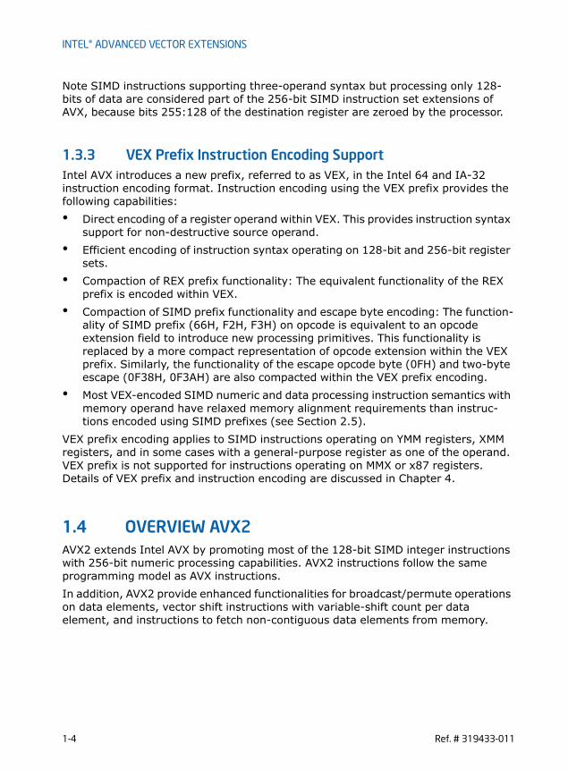
Note SIMD instructions supporting three-operand syntax but processing only 128-bits of data are considered part of the 256-bit SIMD instruction set extensions of AVX, because bits 255:128 of the destination register are zeroed by the processor.
1.3.3 VEX Prefix Instruction Encoding SupportIntel AVX introduces a new prefix, referred to as VEX, in the Intel 64 and IA-32 instruction encoding format. Instruction encoding using the VEX prefix provides the following capabilities:• Direct encoding of a register operand within VEX. This provides instruction syntax
support for non-destructive source operand. • Efficient encoding of instruction syntax operating on 128-bit and 256-bit register
sets.• Compaction of REX prefix functionality: The equivalent functionality of the REX
prefix is encoded within VEX. • Compaction of SIMD prefix functionality and escape byte encoding: The function-
ality of SIMD prefix (66H, F2H, F3H) on opcode is equivalent to an opcode extension field to introduce new processing primitives. This functionality is replaced by a more compact representation of opcode extension within the VEX prefix. Similarly, the functionality of the escape opcode byte (0FH) and two-byte escape (0F38H, 0F3AH) are also compacted within the VEX prefix encoding.
• Most VEX-encoded SIMD numeric and data processing instruction semantics with memory operand have relaxed memory alignment requirements than instruc-tions encoded using SIMD prefixes (see Section 2.5).
VEX prefix encoding applies to SIMD instructions operating on YMM registers, XMM registers, and in some cases with a general-purpose register as one of the operand. VEX prefix is not supported for instructions operating on MMX or x87 registers. Details of VEX prefix and instruction encoding are discussed in Chapter 4.
1.4 OVERVIEW AVX2AVX2 extends Intel AVX by promoting most of the 128-bit SIMD integer instructions with 256-bit numeric processing capabilities. AVX2 instructions follow the same programming model as AVX instructions. In addition, AVX2 provide enhanced functionalities for broadcast/permute operations on data elements, vector shift instructions with variable-shift count per data element, and instructions to fetch non-contiguous data elements from memory.
1-4 Ref. # 319433-011

INTEL® ADVANCED VECTOR EXTENSIONS
1.5 FUNCTIONAL OVERVIEWIntel AVX and FMA provide comprehensive functional improvements over previous generations of SIMD instruction extensions. The functional improvements include:• 256-bit floating-point arithmetic primitives: AVX enhances existing 128-bit
floating-point arithmetic instructions with 256-bit capabilities for floating-point processing. FMA provides additional set of 256-bit floating-point processing capabilities with a rich set of fused-multiply-add and fused multiply-subtract primitives.
• Enhancements for flexible SIMD data movements: AVX provides a number of new data movement primitives to enable efficient SIMD programming in relation to loading non-unit-strided data into SIMD registers, intra-register SIMD data manipulation, conditional expression and branch handling, etc. Enhancements for SIMD data movement primitives cover 256-bit and 128-bit vector floating-point data, and 128-bit integer SIMD data processing using VEX-encoded instruc-tions.
Several key categories of functional improvements in AVX and FMA are summarized in the following subsections.
1.5.1 256-bit Floating-Point Arithmetic Processing EnhancementsIntel AVX provides 35 256-bit floating-point arithmetic instructions. The arithmetic operations cover add, subtract, multiply, divide, square-root, compare, max, min, round, etc., on single-precision and double-precision floating-point data. The enhancement in AVX on floating-point compare operation provides 32 condi-tional predicates to improve programming flexibility in evaluating conditional expres-sions.FMA provides 36 256-bit floating-point instructions to perform computation on 256-bit vectors. The arithmetic operations cover fused multiply-add, fused multiply-subtract, fused multiply add/subtract interleave, signed-reversed multiply on fused multiply-add and multiply-subtract.
1.5.2 256-bit Non-Arithmetic Instruction EnhancementsIntel AVX provides new primitives for handling data movement within 256-bit floating-point vectors and promotes many 128-bit floating data processing instruc-tions to handle 256-bit floating-point vectors. AVX includes 39 256-bit data processing instructions that are promoted from previous generations of SIMD instruction extensions, ranging from logical, blend, convert, test, unpacking, shuffling, load and stores. AVX introduces 18 new data processing instructions that operate on 256-bit vectors. These new primitives cover the following operations:
Ref. # 319433-011 1-5

INTEL® ADVANCED VECTOR EXTENSIONS
• Non-unit-stride fetching of SIMD data. AVX provides several flexible SIMD floating-point data fetching primitives:
— broadcast of single or multiple data elements into a 256-bit destination,
— masked move primitives to load or store SIMD data elements conditionally,• Intra-register manipulation of SIMD data elements. AVX provides several flexible
SIMD floating-point data manipulation primitives:
— insert/extract multiple SIMD floating-point data elements to/from 256-bit SIMD registers
— permute primitives to facilitate efficient manipulation of floating-point data elements in 256-bit SIMD registers
• Branch handling. AVX provides several primitives to enable handling of branches in SIMD programming:
— new variable blend instructions supports four-operand syntax with non-destructive source syntax. This is more flexible than the equivalent SSE4 instruction syntax which uses the XMM0 register as the implied mask for blend selection.
— Packed TEST instructions for floating-point data.
1.5.3 Arithmetic Primitives for 128-bit Vector and Scalar processing
Intel AVX provides 131 128-bit numeric processing instructions that employ VEX-prefix encoding. These VEX-encoded instructions generally provide the same func-tionality over instructions operating on XMM register that are encoded using SIMD prefixes. The 128-bit numeric processing instructions in AVX cover floating-point and integer data processing across 128-bit vector and scalar processing. The enhancement in AVX on 128-bit floating-point compare operation provides 32 conditional predicates to improve programming flexibility in evaluating conditional expressions. This contrasts with floating-point SIMD compare instructions in SSE and SSE2 supporting only 8 conditional predicates.FMA provides 60 128-bit floating-point instructions to process 128-bit vector and scalar data. The arithmetic operations cover fused multiply-add, fused multiply-subtract, signed-reversed multiply on fused multiply-add and multiply-subtract.
1.5.4 Non-Arithmetic Primitives for 128-bit Vector and Scalar Processing
Intel AVX provides 126 data processing instructions that employ VEX-prefix encoding. These VEX-encoded instructions generally provide the same functionality over instructions operating on XMM register that are encoded using SIMD prefixes.
1-6 Ref. # 319433-011

INTEL® ADVANCED VECTOR EXTENSIONS
The 128-bit data processing instructions in AVX cover floating-point and integer data movement primitives. Additional enhancements in AVX on 128-bit data processing primitives include 16 new instructions with the following capabilities:• Non-unit-strided fetching of SIMD data. AVX provides several flexible SIMD
floating-point data fetching primitives:
— broadcast of single data element into a 128-bit destination,
— masked move primitives to load or store SIMD data elements conditionally,• Intra-register manipulation of SIMD data elements. AVX provides several flexible
SIMD floating-point data manipulation primitives:
— permute primitives to facilitate efficient manipulation of floating-point data elements in 128-bit SIMD registers
• Branch handling. AVX provides several primitives to enable handling of branches in SIMD programming:
— new variable blend instructions supports four-operand syntax with non-destructive source syntax. Branching conditions dependent on floating-point data or integer data can benefit from Intel AVX. This is more flexible than non-VEX encoded instruction syntax that uses the XMM0 register as implied mask for blend selection. While variable blend with implied XMM0 syntax is supported in SSE4 using SIMD prefix encoding, VEX-encoded 128-bit variable blend instructions only support the more flexible four-operand syntax.
— Packed TEST instructions for floating-point data.
1.5.5 AVX2 and 256-bit Vector Integer ProcessingAVX2 promotes the vast majority of 128-bit integer SIMD instruction sets to operate with 256-bit wide YMM registers. AVX2 instructions are encoded using the VEX prefix and require the same operating system support as AVX. Generally, most of the promoted 256-bit vector integer instructions follow the 128-bit lane operation, similar to the promoted 256-bit floating-point SIMD instructions in AVX.Newer functionalities in AVX2 generally fall into the following categories:• Fetching non-contiguous data elements from memory using vector-index
memory addressing. These “gather” instructions introduce a new memory-addressing form, consisting of a base register and multiple indices specified by a vector register (either XMM or YMM). Data elements sizes of 32 and 64-bits are supported, and data types for floating-point and integer elements are also supported.
• Cross-lane functionalities are provided with several new instructions for broadcast and permute operations. Some of the 256-bit vector integer instruc-tions promoted from legacy SSE instruction sets also exhibit cross-lane behavior, e.g. VPMOVZ/VPMOVS family.
Ref. # 319433-011 1-7

INTEL® ADVANCED VECTOR EXTENSIONS
• AVX2 complements the AVX instructions that are typed for floating-point operation with a full compliment of equivalent set for operating with 32/64-bit integer data elements.
• Vector shift instructions with per-element shift count. Data elements sizes of 32 and 64-bits are supported.
1.6 GENERAL PURPOSE INSTRUCTION SET ENHANCEMENTS
Enhancements in the general-purpose instruction set consist of several categories:• A rich collection of instructions to manipulate integer data at bit-granularity. Most
of the bit-manipulation instructions employ VEX-prefix encoding to support three-operand syntax with non-destructive source operands. Two of the bit-manipulating instructions (LZCNT, TZCNT) are not encoded using VEX. The VEX-encoded bit-manipulation instructions include: ANDN, BEXTR, BLSI, BLSMSK, BLSR, BZHI, PEXT, PDEP, LZCNT, TZCNT, SARX, SHLX, SHRX, and RORX.
• Enhanced integer multiply instruction (MULX) in conjunctions with some of the bit-manipulation instructions allow software to accelerate calculation of large integer numerics (wider than 128-bits).
• INVPCID instruction targets system software that manages processor context IDs.
Details of enumerating these instruction enhancements are described in detail in Section 2.2.4.
1-8 Ref. # 319433-011

APPLICATION PROGRAMMING MODEL
CHAPTER 2APPLICATION PROGRAMMING MODEL
The application programming model for AVX2 is the same as Intel AVX and FMA. The VEX-encoded general-purpose instructions generally follows legacy general-purpose instructions. They are summarized as follows:• Section 2.1 through Section 2.8 apply to AVX2, AVX and FMA. The OS support
and detection process is identical for AVX2, AVX, F16C, and FMA• The numeric exception behavior of FMA is similar to previous generations of SIMD
floating-point instructions. The specific details are described in Section 2.3.CPUID instruction details for detecting AVX, FMA, AESNI, PCLMULQDQ, AVX2, BMI1, BMI2, LZCNT and INVPCID are described in Section 2.9.
2.1 DETECTION OF PCLMULQDQ AND AES INSTRUCTIONS
Before an application attempts to use the following AES instructions: AESDEC/AESDECLAST/AESENC/AESENCLAST/AESIMC/AESKEYGENASSIST, it must check that the processor supports the AES extensions. AES extensions is supported if CPUID.01H:ECX.AES[bit 25] = 1. Prior to using PCLMULQDQ instruction, application must check if CPUID.01H:ECX.PCLMULQDQ[bit 1] = 1.
Operating systems that support handling SSE state will also support applications that use AES extensions and PCLMULQDQ instruction. This is the same requirement for SSE2, SSE3, SSSE3, and SSE4.
2.2 DETECTION OF AVX AND FMA INSTRUCTIONS AVX and FMA operate on the 256-bit YMM register state. System software require-ments to support YMM state is described in Chapter 3.Application detection of new instruction extensions operating on the YMM state follows the general procedural flow in Figure 2-1.
Ref. # 319433-011 2-1

APPLICATION PROGRAMMING MODEL
Prior to using AVX, the application must identify that the operating system supports the XGETBV instruction, the YMM register state, in addition to processor’s support for YMM state management using XSAVE/XRSTOR and AVX instructions. The following simplified sequence accomplishes both and is strongly recommended.1) Detect CPUID.1:ECX.OSXSAVE[bit 27] = 1 (XGETBV enabled for application use1)2) Issue XGETBV and verify that XFEATURE_ENABLED_MASK[2:1] = ‘11b’ (XMM state and YMM state are enabled by OS).3) detect CPUID.1:ECX.AVX[bit 28] = 1 (AVX instructions supported).(Step 3 can be done in any order relative to 1 and 2)The following pseudocode illustrates this recommended application AVX detection process:----------------------------------------------------------------------------------------INT supports_AVX(){ ; result in eax
mov eax, 1cpuid
Figure 2-1. General Procedural Flow of Application Detection of AVX
1. If CPUID.01H:ECX.OSXSAVE reports 1, it also indirectly implies the processor supports XSAVE, XRSTOR, XGETBV, processor extended state bit vector XFEATURE_ENALBED_MASK register. Thus an application may streamline the checking of CPUID feature flags for XSAVE and OSXSAVE. XSETBV is a privileged instruction.
Implied HW support for
Check enabled state in
XFEM via XGETBV
Check feature flag for Instruction set
Check feature flag
CPUID.1H:ECX.OXSAVE = 1?
OS provides processorextended state management
State ok to use
XSAVE, XRSTOR, XGETBV, XFEATURE_ENABLED_MASK
enabled Instructions
Yes
2-2 Ref. # 319433-011

APPLICATION PROGRAMMING MODEL
and ecx, 018000000Hcmp ecx, 018000000H; check both OSXSAVE and AVX feature flags jne not_supported; processor supports AVX instructions and XGETBV is enabled by OSmov ecx, 0; specify 0 for XFEATURE_ENABLED_MASK registerXGETBV; result in EDX:EAXand eax, 06Hcmp eax, 06H; check OS has enabled both XMM and YMM state supportjne not_supportedmov eax, 1jmp doneNOT_SUPPORTED:mov eax, 0done:
}-------------------------------------------------------------------------------Note: It is unwise for an application to rely exclusively on CPUID.1:ECX.AVX[bit 28] or at all on CPUID.1:ECX.XSAVE[bit 26]: These indicate hardware support but not operating system support. If YMM state management is not enabled by an operating systems, AVX instructions will #UD regardless of CPUID.1:ECX.AVX[bit 28]. “CPUID.1:ECX.XSAVE[bit 26] = 1” does not guarantee the OS actually uses the XSAVE process for state management.These steps above also apply to enhanced 128-bit SIMD floating-pointing instruc-tions in AVX (using VEX prefix-encoding) that operate on the YMM states. Application detection of VEX-encoded AES is described in Section 2.2.2.
2.2.1 Detection of FMA Hardware support for FMA is indicated by CPUID.1:ECX.FMA[bit 12]=1. Application Software must identify that hardware supports AVX as explained in Section 2.2, after that it must also detect support for FMA by CPUID.1:ECX.FMA[bit 12]. The recommended pseudocode sequence for detection of FMA is: ----------------------------------------------------------------------------------------INT supports_fma(){ ; result in eax
mov eax, 1cpuidand ecx, 018001000H
Ref. # 319433-011 2-3

APPLICATION PROGRAMMING MODEL
cmp ecx, 018001000H; check OSXSAVE, AVX, FMA feature flags jne not_supported; processor supports AVX,FMA instructions and XGETBV is enabled by OSmov ecx, 0; specify 0 for XFEATURE_ENABLED_MASK registerXGETBV; result in EDX:EAXand eax, 06Hcmp eax, 06H; check OS has enabled both XMM and YMM state supportjne not_supportedmov eax, 1jmp doneNOT_SUPPORTED:mov eax, 0done:
}-------------------------------------------------------------------------------Note that FMA comprises of 256-bit and 128-bit SIMD instructions operating on YMM states.
2.2.2 Detection of VEX-Encoded AES and VPCLMULQDQVAESDEC/VAESDECLAST/VAESENC/VAESENCLAST/VAESIMC/VAESKEYGENASSIST instructions operate on YMM states. The detection sequence must combine checking for CPUID.1:ECX.AES[bit 25] = 1 and the sequence for detection application support for AVX. Similarly, the detection sequence for VPCLMULQDQ must combine checking for CPUID.1:ECX.PCLMULQDQ[bit 1] = 1 and the sequence for detection application support for AVX. This is shown in the pseudocode:----------------------------------------------------------------------------------------INT supports_VAES(){ ; result in eax
mov eax, 1cpuidand ecx, 01A000000Hcmp ecx, 01A000000H; check OSXSAVE, AVX and AES feature flags jne not_supported
2-4 Ref. # 319433-011

APPLICATION PROGRAMMING MODEL
; processor supports AVX and VEX.128-encoded AES instructions and XGETBV is enabled by OS
mov ecx, 0; specify 0 for XFEATURE_ENABLED_MASK registerXGETBV; result in EDX:EAXand eax, 06Hcmp eax, 06H; check OS has enabled both XMM and YMM state supportjne not_supportedmov eax, 1jmp doneNOT_SUPPORTED:mov eax, 0done:
}
INT supports_VPCLMULQDQ(){ ; result in eax
mov eax, 1cpuidand ecx, 018000002Hcmp ecx, 018000002H; check OSXSAVE, AVX and PCLMULQDQ feature flags jne not_supported; processor supports AVX and VPCLMULQDQ instructions and XGETBV is
enabled by OSmov ecx, 0; specify 0 for XFEATURE_ENABLED_MASK registerXGETBV; result in EDX:EAXand eax, 06Hcmp eax, 06H; check OS has enabled both XMM and YMM state supportjne not_supportedmov eax, 1jmp doneNOT_SUPPORTED:mov eax, 0done:
}-------------------------------------------------------------------------------
Ref. # 319433-011 2-5

APPLICATION PROGRAMMING MODEL
2.2.3 Detection of AVX2 Hardware support for AVX2 is indicated by CPUID.(EAX=07H, ECX=0H):EBX.AVX2[bit 5]=1. Application Software must identify that hardware supports AVX as explained in Section 2.2, after that it must also detect support for AVX2 by checking CPUID.(EAX=07H, ECX=0H):EBX.AVX2[bit 5]. The recommended pseudocode sequence for detection of AVX2 is: ----------------------------------------------------------------------------------------INT supports_avx2(){ ; result in eax
mov eax, 1cpuidand ecx, 018000000Hcmp ecx, 018000000H; check both OSXSAVE and AVX feature flags jne not_supported; processor supports AVX instructions and XGETBV is enabled by OSmov eax, 7mov ecx, 0cpuidand ebx, 20Hcmp ebx, 20H; check AVX2 feature flags jne not_supportedmov ecx, 0; specify 0 for XFEATURE_ENABLED_MASK registerXGETBV; result in EDX:EAXand eax, 06Hcmp eax, 06H; check OS has enabled both XMM and YMM state supportjne not_supportedmov eax, 1jmp doneNOT_SUPPORTED:mov eax, 0done:
}-------------------------------------------------------------------------------
2-6 Ref. # 319433-011

APPLICATION PROGRAMMING MODEL
2.2.4 Detection VEX-encoded GPR InstructionsVEX-encoded general-purpose instructions do not operate on YMM registers and are similar to legacy general-purpose instructions. Checking for OSXSAVE or YMM support is not required. There are separate feature flags for the following subsets of instructions that operate on general purpose registers, and the detection requirements for hardware support are:CPUID.(EAX=07H, ECX=0H):EBX.BMI1[bit 3]: if 1 indicates the processor supports the first group of advanced bit manipulation extensions (ANDN, BEXTR, BLSI, BLSMK, BLSR, TZCNT);CPUID.(EAX=07H, ECX=0H):EBX.BMI2[bit 8]: if 1 indicates the processor supports the second group of advanced bit manipulation extensions (BZHI, MULX, PDEP, PEXT, RORX, SARX, SHLX, SHRX);CPUID.(EAX=07H, ECX=0H):EBX.INVPCID[bit 10]: if 1 indicates the processor supports the INVPCID instruction for system software that manages processor context ID.CPUID.EAX=80000001H:ECX.LZCNT[bit 5]: if 1 indicates the processor supports the LZCNT instruction.
2.3 FUSED-MULTIPLY-ADD (FMA) NUMERIC BEHAVIORFMA instructions can perform fused-multiply-add operations (including fused-multiply-subtract, and other varieties) on packed and scalar data elements in the instruction operands. Separate FMA instructions are provided to handle different types of arithmetic operations on the three source operands.FMA instruction syntax is defined using three source operands and the first source operand is updated based on the result of the arithmetic operations of the data elements of 128-bit or 256-bit operands, i.e. The first source operand is also the destination operand.The arithmetic FMA operation performed in an FMA instruction takes one of several forms, r=(x*y)+z, r=(x*y)-z, r=-(x*y)+z, or r=-(x*y)-z. Packed FMA instructions can perform eight single-precision FMA operations or four double-precision FMA operations with 256-bit vectors. Scalar FMA instructions only perform one arithmetic operation on the low order data element. The content of the rest of the data elements in the lower 128-bits of the destination operand is preserved. the upper 128bits of the destination operand are filled with zero. An arithmetic FMA operation of the form, r=(x*y)+z, takes two IEEE-754-2008 single (double) precision values and multiplies them to form an infinite precision intermediate value. This intermediate value is added to a third single (double) preci-sion value (also at infinite precision) and rounded to produce a single (double) preci-sion result.
Ref. # 319433-011 2-7

APPLICATION PROGRAMMING MODEL
Table 2-2 describes the numerical behavior of the FMA operation, r=(x*y)+z, r=(x*y)-z, r=-(x*y)+z, r=-(x*y)-z for various input values. The input values can be 0, finite non-zero (F in Table 2-2), infinity of either sign (INF in Table 2-2), positive infinity (+INF in Table 2-2), negative infinity (-INF in Table 2-2), or NaN (including QNaN or SNaN). If any one of the input values is a NAN, the result of FMA operation, r, may be a quietized NAN. The result can be either Q(x), Q(y), or Q(z), see Table 2-2. If x is a NaN, then:
• Q(x) = x if x is QNaN or
• Q(x) = the quietized NaN obtained from x if x is SNaNThe notation for the output value in Table 2-2 are:• “+INF”: positive infinity, “-INF”: negative infinity. When the result depends on a
conditional expression, both values are listed in the result column and the condition is described in the comment column.
• QNaNIndefinite represents the QNaN which has the sign bit equal to 1, the most significand field equal to 1, and the remaining significand field bits equal to 0.
• The summation or subtraction of 0s or identical values in FMA operation can lead to the following situations shown in Table 2-1
• If the FMA computation represents an invalid operation (e.g. when adding two INF with opposite signs)), the invalid exception is signaled, and the MXCSR.IE flag is set.
Table 2-1. Rounding behavior of Zero Result in FMA Operationx*y z (x*y) + z (x*y) - z - (x*y) + z - (x*y) - z
(+0) (+0)+0 in all rounding modes
- 0 when rounding down, and +0 otherwise
- 0 when rounding down, and +0 otherwise
- 0 in all rounding modes
(+0) (-0)- 0 when rounding down, and +0 otherwise
+0 in all rounding modes
- 0 in all rounding modes
- 0 when rounding down, and +0 otherwise
(-0) (+0)- 0 when rounding down, and +0 otherwise
- 0 in all rounding modes
+ 0 in all rounding modes
- 0 when rounding down, and +0 otherwise
(-0) (-0)- 0 in all rounding modes
- 0 when rounding down, and +0 otherwise
- 0 when rounding down, and +0 otherwise
+ 0 in all rounding modes
F -F- 0 when rounding down, and +0 otherwise
2*F -2*F - 0 when rounding down, and +0 otherwise
F F2*F - 0 when
rounding down, and +0 otherwise
- 0 when rounding down, and +0 otherwise
-2*F
2-8 Ref. # 319433-011

APPLICATION PROGRAMMING MODEL
Table 2-2. FMA Numeric Behavior x
(multiplicand)
y (multiplier)
zr=(x*y)
+zr=(x*y)
-zr =
-(x*y)+zr=
-(x*y)-zComment
NaN 0, F, INF, NaN
0, F, INF, NaN
Q(x) Q(x) Q(x) Q(x) Signal invalid exception if x or y or z is SNaN
0, F, INF NaN 0, F, INF, NaN
Q(y) Q(y) Q(y) Q(y) Signal invalid exception if y or z is SNaN
0, F, INF 0, F, INF NaN Q(z) Q(z) Q(z) Q(z) Signal invalid exception if z is SNaN
INF F, INF +INF
+INF QNaNIn-definite
QNaNIn-definite
-INF if x*y and z have the same sign
QNaNIn-definite
-INF +INF QNaNIn-definite
if x*y and z have opposite signs
INF F, INF -INF -INF QNaNIn-definite
QNaNIn-definite
+INF if x*y and z have the same sign
QNaNIn-definite
+INF -INF QNaNIn-definite
if x*y and z have opposite signs
INF F, INF 0, F +INF +INF -INF -INF if x and y have the same sign
-INF -INF +INF +INF if x and y have opposite signs
INF 0 0, F, INF
QNaNIn-definite
QNaNIn-definite
QNaNIn-definite
QNaNIn-definite
Signal invalid exception
0 INF 0, F, INF
QNaNIn-definite
QNaNIn-definite
QNaNIn-definite
QNaNIn-definite
Signal invalid exception
F INF +INF
+INF QNaNIn-definite
QNaNIn-definite
-INF if x*y and z have the same sign
QNaNIn-definite
-INF +INF QNaNIn-definite
if x*y and z have opposite signs
Ref. # 319433-011 2-9

APPLICATION PROGRAMMING MODEL
F INF -INF -INF QNaNIn-definite
QNaNIn-definite
+INF if x*y and z have the same sign
QNaNIn-definite
+INF -INF QNaNIn-definite
if x*y and z have opposite signs
F INF 0,F +INF +INF -INF -INF if x * y > 0
-INF -INF +INF +INF if x * y < 0
0,F 0,F INF +INF -INF +INF -INF if z > 0
-INF +INF -INF +INF if z < 0
0 0 0 0 0 0 0 The sign of the result depends on the sign of the operands and on the rounding mode. The product x*y is +0 or -0, depending on the signs of x and y. The sum-mation/subtrac-tion of the zero representing (x*y) and the zero represent-ing z can lead to one of the four cases shown in Table 2-1.
0 F 0 0 0 0 0
F 0 0 0 0 0 0
0 0 F z -z z -z
0 F F z -z z -z
x (multiplicand)
y (multiplier)
z r=(x*y)+z
r=(x*y) -z
r = -(x*y)+z
r=-(x*y)-z
Comment
2-10 Ref. # 319433-011

APPLICATION PROGRAMMING MODEL
If unmasked floating-point exceptions are signaled (invalid operation, denormal operand, overflow, underflow, or inexact result) the result register is left unchanged and a floating-point exception handler is invoked.
2.3.1 FMA Instruction Operand Order and Arithmetic BehaviorFMA instruction mnemonics are defined explicitly with an ordered three digits, e.g. VFMADD132PD. The value of each digit refers to the ordering of the three source operand as defined by instruction encoding specification:• ‘1’: The first source operand (also the destination operand) in the syntactical
order listed in this specification.• ‘2’: The second source operand in the syntactical order. This is a YMM/XMM
register, encoded using VEX prefix.• ‘3’: The third source operand in the syntactical order. The first and third operand
are encoded following ModR/M encoding rules. The ordering of each digit within the mnemonic refers to the floating-point data listed on the right-hand side of the arithmetic equation of each FMA operation (see Table 2-2):
F 0 F z -z z -z
F F 0 x*y x*y -x*y -x*y Rounded to the destination pre-cision, with bounded expo-nent
F F F (x*y)+z (x*y)-z -(x*y)+z -(x*y)-z Rounded to the destination pre-cision, with bounded expo-nent; however, if the exact val-ues of x*y and z are equal in magnitude with signs resulting in the FMA operation pro-ducing 0, the rounding behav-ior described in Table 2-1.
x (multiplicand)
y (multiplier)
z r=(x*y)+z
r=(x*y) -z
r = -(x*y)+z
r=-(x*y)-z
Comment
Ref. # 319433-011 2-11

APPLICATION PROGRAMMING MODEL
• The first position in the three digits of a FMA mnemonic refers to the operand position of the first FP data expressed in the arithmetic equation of FMA operation, the multiplicand.
• The second position in the three digits of a FMA mnemonic refers to the operand position of the second FP data expressed in the arithmetic equation of FMA operation, the multiplier.
• The third position in the three digits of a FMA mnemonic refers to the operand position of the FP data being added/subtracted to the multiplication result.
Note the non-numerical result of an FMA operation does not resemble the mathemat-ically-defined commutative property between the multiplicand and the multiplier values (see Table 2-2). Consequently, software tools (such as an assembler) may support a complementary set of FMA mnemonics for each FMA instruction for ease of programming to take advantage of the mathematical property of commutative multi-plications. For example, an assembler may optionally support the complementary mnemonic “VFMADD312PD“ in addition to the true mnemonic “VFMADD132PD“. The assembler will generate the same instruction opcode sequence corresponding to VFMADD132PD. The processor executes VFMADD132PD and report any NAN condi-tions based on the definition of VFMADD132PD. Similarly, if the complementary mnemonic VFMADD123PD is supported by an assembler at source level, it must generate the opcode sequence corresponding to VFMADD213PD; the complementary mnemonic VFMADD321PD must produce the opcode sequence defined by VFMADD231PD. In the absence of FMA operations reporting a NAN result, the numer-ical results of using either mnemonic with an assembler supporting both mnemonics will match the behavior defined in Table 2-2. Support for the complementary FMA mnemonics by software tools is optional.
2.4 ACCESSING YMM REGISTERSThe lower 128 bits of a YMM register is aliased to the corresponding XMM register. Legacy SSE instructions (i.e. SIMD instructions operating on XMM state but not using the VEX prefix, also referred to non-VEX encoded SIMD instructions) will not access the upper bits (255:128) of the YMM registers. AVX and FMA instructions with a VEX prefix and vector length of 128-bits zeroes the upper 128 bits of the YMM register. See Chapter 2, “Programming Considerations with 128-bit SIMD Instructions” for more details.
Upper bits of YMM registers (255:128) can be read and written by many instructions with a VEX.256 prefix.
XSAVE and XRSTOR may be used to save and restore the upper bits of the YMM regis-ters.
2-12 Ref. # 319433-011

APPLICATION PROGRAMMING MODEL
2.5 MEMORY ALIGNMENT Memory alignment requirements on VEX-encoded instruction differ from non-VEX-encoded instructions. Memory alignment applies to non-VEX-encoded SIMD instruc-tions in three categories:• Explicitly-aligned SIMD load and store instructions accessing 16 bytes of memory
(e.g. MOVAPD, MOVAPS, MOVDQA, etc.). These instructions always require memory address to be aligned on 16-byte boundary.
• Explicitly-unaligned SIMD load and store instructions accessing 16 bytes or less of data from memory (e.g. MOVUPD, MOVUPS, MOVDQU, MOVQ, MOVD, etc.). These instructions do not require memory address to be aligned on 16-byte boundary.
• The vast majority of arithmetic and data processing instructions in legacy SSE instructions (non-VEX-encoded SIMD instructions) support memory access semantics. When these instructions access 16 bytes of data from memory, the memory address must be aligned on 16-byte boundary.
Most arithmetic and data processing instructions encoded using the VEX prefix and performing memory accesses have more flexible memory alignment requirements than instructions that are encoded without the VEX prefix. Specifically, • With the exception of explicitly aligned 16 or 32 byte SIMD load/store instruc-
tions, most VEX-encoded, arithmetic and data processing instructions operate in a flexible environment regarding memory address alignment, i.e. VEX-encoded instruction with 32-byte or 16-byte load semantics will support unaligned load operation by default. Memory arguments for most instructions with VEX prefix operate normally without causing #GP(0) on any byte-granularity alignment (unlike Legacy SSE instructions). The instructions that require explicit memory alignment requirements are listed in Table 2-4.
Software may see performance penalties when unaligned accesses cross cacheline boundaries, so reasonable attempts to align commonly used data sets should continue to be pursued.Atomic memory operation in Intel 64 and IA-32 architecture is guaranteed only for a subset of memory operand sizes and alignment scenarios. The list of guaranteed atomic operations are described in Section 7.1.1 of IA-32 Intel® Architecture Soft-ware Developer’s Manual, Volumes 3A. AVX and FMA instructions do not introduce any new guaranteed atomic memory operations.AVX and FMA will generate an #AC(0) fault on misaligned 4 or 8-byte memory refer-ences in Ring-3 when CR0.AM=1. 16 and 32-byte memory references will not generate #AC(0) fault. See Table 2-3 for details.Certain AVX instructions always require 16- or 32-byte alignment (see the complete list of such instructions in Table 2-4). These instructions will #GP(0) if not aligned to 16-byte boundaries (for 16-byte granularity loads and stores) or 32-byte boundaries (for 32-byte loads and stores).
Ref. # 319433-011 2-13

APPLICATION PROGRAMMING MODEL
Table 2-3. Alignment Faulting Conditions when Memory Access is Not Aligned EFLAGS.AC==1 && Ring-3 && CR0.AM == 1 0 1
Inst
ruct
ion
Type
AVX
, FM
A, A
VX
2,
16- or 32-byte “explicitly unaligned” loads and stores (see Table 2-5)
no fault no fault
VEX op YMM, m256 no fault no fault
VEX op XMM, m128 no fault no fault
“explicitly aligned” loads and stores (see Table 2-4)
#GP(0) #GP(0)
2, 4, or 8-byte loads and stores no fault #AC(0)
SSE
16 byte “explicitly unaligned” loads and stores (see Table 2-5)
no fault no fault
op XMM, m128 #GP(0) #GP(0)
“explicitly aligned” loads and stores (see Table 2-4)
#GP(0) #GP(0)
2, 4, or 8-byte loads and stores no fault #AC(0)
Table 2-4. Instructions Requiring Explicitly Aligned Memory
Require 16-byte alignment Require 32-byte alignment
(V)MOVDQA xmm, m128 VMOVDQA ymm, m256
(V)MOVDQA m128, xmm VMOVDQA m256, ymm
(V)MOVAPS xmm, m128 VMOVAPS ymm, m256
(V)MOVAPS m128, xmm VMOVAPS m256, ymm
(V)MOVAPD xmm, m128 VMOVAPD ymm, m256
(V)MOVAPD m128, xmm VMOVAPD m256, ymm
(V)MOVNTPS m128, xmm VMOVNTPS m256, ymm
(V)MOVNTPD m128, xmm VMOVNTPD m256, ymm
(V)MOVNTDQ m128, xmm VMOVNTDQ m256, ymm
(V)MOVNTDQA xmm, m128 VMOVNTDQA ymm, m256
2-14 Ref. # 319433-011

APPLICATION PROGRAMMING MODEL
2.6 SIMD FLOATING-POINT EXCEPTIONSAVX and FMA instructions can generate SIMD floating-point exceptions (#XM) and respond to exception masks in the same way as Legacy SSE instructions. When CR4.OSXMMEXCPT=0 any unmasked FP exceptions generate an Undefined Opcode exception (#UD).
AVX FP exceptions are created in a similar fashion (differing only in number of el-ements) to Legacy SSE and SSE2 instructions capable of generating SIMD floating-point exceptions.
AVX introduces no new arithmetic operations (AVX floating-point are analogues ofexisting Legacy SSE instructions). FMA introduces new arithmetic operations, de-tailed FMA numeric behavior are described in Section 2.3.
2.7 INSTRUCTION EXCEPTION SPECIFICATIONTo use this reference of instruction exceptions, look at each instruction for a descrip-tion of the particular exception type of interest. For example, ADDPS contains the entry:“See Exceptions Type 2”In this entry, “Type2” can be looked up in Table 2-6.
Table 2-5. Instructions Not Requiring Explicit Memory Alignment
(V)MOVDQU xmm, m128
(V)MOVDQU m128, m128
(V)MOVUPS xmm, m128
(V)MOVUPS m128, xmm
(V)MOVUPD xmm, m128
(V)MOVUPD m128, xmm
VMOVDQU ymm, m256
VMOVDQU m256, ymm
VMOVUPS ymm, m256
VMOVUPS m256, ymm
VMOVUPD ymm, m256
VMOVUPD m256, ymm
Ref. # 319433-011 2-15

APPLICATION PROGRAMMING MODEL
The instruction’s corresponding CPUID feature flag can be identified in the fourth column of the Instruction summary table. Note: #UD on CPUID feature flags=0 is not guaranteed in a virtualized environment if the hardware supports the feature flag.
Table 2-6. Exception class description
See Table 2-7 for lists of instructions in each exception class.
Exception Class Instruction Set Mem Arg Floating-Point Exceptions (#XM)
Type 1 AVX, AVX2,Legacy SSE
16/32 byte explicitly aligned
none
Type 2 AVX, FMA, AVX2,Legacy SSE
16/32 byte not explic-itly aligned
yes
Type 3 AVX, FMA, Legacy SSE
< 16 byte yes
Type 4 AVX, AVX2,Legacy SSE
16/32 byte not explic-itly aligned
no
Type 5 AVX, AVX2,Legacy SSE
< 16 byte no
Type 6 AVX, AVX2 (no Legacy SSE)
Varies (At present, none do)
Type 7 AVX, AVX2Legacy SSE
none none
Type 8 AVX none none
Type 11 F16C 8 or 16 byte, Not explic-itly aligned, no AC#
yes
Type 12 AVX2 Not explicitlyaligned, no AC#
no
2-16 Ref. # 319433-011

APPLICATION PROGRAMMING MODEL
Table 2-7. Instructions in each Exception ClassException Class Instruction
Type 1 (V)MOVAPD, (V)MOVAPS, (V)MOVDQA, (V)MOVNTDQ, (V)MOVNTDQA, (V)MOVNTPD, (V)MOVNTPS
Type 2 (V)ADDPD, (V)ADDPS, (V)ADDSUBPD, (V)ADDSUBPS, (V)CMPPD, (V)CMPPS, (V)CVTDQ2PS, (V)CVTPD2DQ, (V)CVTPD2PS, (V)CVTPS2DQ, (V)CVTTPD2DQ, (V)CVTTPS2DQ, (V)DIVPD, (V)DIVPS, (V)DPPD*, (V)DPPS*, VFMADD132PD, VFMADD213PD, VFMADD231PD, VFMADD132PS, VFMADD213PS, VFMADD231PS, VFMADDSUB132PD, VFMADDSUB213PD, VFMADDSUB231PD, VFMADDSUB132PS, VFMADDSUB213PS, VFMADDSUB231PS, VFMSUBADD132PD, VFMSUBADD213PD, VFMSUBADD231PD, VFMSUBADD132PS, VFMSUBADD213PS, VFMSUBADD231PS, VFMSUB132PD, VFMSUB213PD, VFMSUB231PD, VFMSUB132PS, VFMSUB213PS, VFMSUB231PS, VFNMADD132PD, VFNMADD213PD, VFNMADD231PD, VFNMADD132PS, VFNMADD213PS, VFNMADD231PS, VFNMSUB132PD, VFNMSUB213PD, VFNMSUB231PD, VFNMSUB132PS, VFNMSUB213PS, VFNMSUB231PS, (V)HADDPD, (V)HADDPS, (V)HSUBPD, (V)HSUBPS, (V)MAXPD, (V)MAXPS, (V)MINPD, (V)MINPS, (V)MULPD, (V)MULPS, (V)ROUNDPS, (V)ROUNDPS, (V)SQRTPD, (V)SQRTPS, (V)SUBPD, (V)SUBPS
Type 3 (V)ADDSD, (V)ADDSS, (V)CMPSD, (V)CMPSS, (V)COMISD, (V)COMISS, (V)CVTPS2PD, (V)CVTSD2SI, (V)CVTSD2SS, (V)CVTSI2SD, (V)CVTSI2SS, (V)CVTSS2SD, (V)CVTSS2SI, (V)CVTTSD2SI, (V)CVTTSS2SI, (V)DIVSD, (V)DIVSS, VFMADD132SD, VFMADD213SD, VFMADD231SD, VFMADD132SS, VFMADD213SS, VFMADD231SS, VFMSUB132SD, VFMSUB213SD, VFMSUB231SD, VFMSUB132SS, VFMSUB213SS, VFMSUB231SS, VFNMADD132SD, VFNMADD213SD, VFNMADD231SD, VFNMADD132SS, VFNMADD213SS, VFNMADD231SS, VFNMSUB132SD, VFNMSUB213SD, VFNMSUB231SD, VFNMSUB132SS, VFNMSUB213SS, VFNMSUB231SS, (V)MAXSD, (V)MAXSS, (V)MINSD, (V)MINSS, (V)MULSD, (V)MULSS, (V)ROUNDSD, (V)ROUNDSS, (V)SQRTSD, (V)SQRTSS, (V)SUBSD, (V)SUBSS, (V)UCOMISD, (V)UCOMISS
Type 4 (V)AESDEC, (V)AESDECLAST, (V)AESENC, (V)AESENCLAST, (V)AESIMC, (V)AESKEYGENASSIST, (V)ANDPD, (V)ANDPS, (V)ANDNPD, (V)ANDNPS, (V)BLENDPD, (V)BLENDPS, VBLENDVPD, VBLENDVPS, (V)LDDQU, (V)MASKMOVDQU, (V)PTEST, VTESTPS, VTESTPD, (V)MOVDQU*, (V)MOVSHDUP, (V)MOVSLDUP, (V)MOVUPD*, (V)MOVUPS*, (V)MPSADBW, (V)ORPD, (V)ORPS, (V)PABSB, (V)PABSW, (V)PABSD, (V)PACKSSWB, (V)PACKSSDW, (V)PACKUSWB, (V)PACKUSDW, (V)PADDB, (V)PADDW, (V)PADDD, (V)PADDQ, (V)PADDSB, (V)PADDSW, (V)PADDUSB, (V)PADDUSW, (V)PALIGNR, (V)PAND, (V)PANDN, (V)PAVGB, (V)PAVGW, (V)PBLENDVB, (V)PBLENDW, (V)PCMP(E/I)STRI/M, (V)PCMPEQB, (V)PCMPEQW, (V)PCMPEQD, (V)PCMPEQQ, (V)PCMPGTB, (V)PCMPGTW, (V)PCMPGTD, (V)PCMPGTQ, (V)PCLMULQDQ, (V)PHADDW, (V)PHADDD, (V)PHADDSW, (V)PHMINPOSUW, (V)PHSUBD, (V)PHSUBW, (V)PHSUBSW, (V)PMADDWD, (V)PMADDUBSW,
Ref. # 319433-011 2-17

APPLICATION PROGRAMMING MODEL
(*) - Additional exception restrictions are present - see the Instruction descriptionfor details
(**) - Instruction behavior on alignment check reporting with mask bits of less thanall 1s are the same as with mask bits of all 1s, i.e. no alignment checks are per-formed.
Table 2-7 classifies exception behaviors for AVX instructions. Within each class of exception conditions that are listed in Table 2-10 through Table 2-16, certain subsets of AVX instructions may be subject to #UD exception depending on the encoded value of the VEX.L field. Table 2-9 provides supplemental information of AVX instruc-tions that may be subject to #UD exception if encoded with incorrect values in the VEX.W or VEX.L field.
Type 4 Continued (V)PMAXSB, (V)PMAXSW, (V)PMAXSD, (V)PMAXUB, (V)PMAXUW, (V)PMAXUD, (V)PMINSB, (V)PMINSW, (V)PMINSD, (V)PMINUB, (V)PMINUW, (V)PMINUD, (V)PMULHUW, (V)PMULHRSW, (V)PMULHW, (V)PMULLW, (V)PMULLD, (V)PMULUDQ, (V)PMULDQ, (V)POR, (V)PSADBW, (V)PSHUFB, (V)PSHUFD, (V)PSHUFHW, (V)PSHUFLW, (V)PSIGNB, (V)PSIGNW, (V)PSIGND, (V)PSLLW, (V)PSLLD, (V)PSLLQ, (V)PSRAW, (V)PSRAD, (V)PSRLW, (V)PSRLD, (V)PSRLQ, (V)PSUBB, (V)PSUBW, (V)PSUBD, (V)PSUBQ, (V)PSUBSB, (V)PSUBSW, (V)PUNPCKHBW, (V)PUNPCKHWD, (V)PUNPCKHDQ, (V)PUNPCKHQDQ, (V)PUNPCKLBW, (V)PUNPCKLWD, (V)PUNPCKLDQ, (V)PUNPCKLQDQ, (V)PXOR, (V)RCPPS, (V)RSQRTPS, (V)SHUFPD, (V)SHUFPS, (V)UNPCKHPD, (V)UNPCKHPS, (V)UNPCKLPD, (V)UNPCKLPS, (V)XORPD, (V)XORPS, VPBLENDD, VPERMD, VPERMPS, VPERMPD, VPERMQ, VPSLLVD, VPSLLVQ, VPSRAVD, VPSRLVD, VPSRLVQ
Type 5 (V)CVTDQ2PD, (V)EXTRACTPS, (V)INSERTPS, (V)MOVD, (V)MOVQ, (V)MOVDDUP, (V)MOVLPD, (V)MOVLPS, (V)MOVHPD, (V)MOVHPS, (V)MOVSD, (V)MOVSS, (V)PEXTRB, (V)PEXTRD, (V)PEXTRW, (V)PEXTRQ, (V)PINSRB, (V)PINSRD, (V)PINSRW, (V)PINSRQ, (V)RCPSS, (V)RSQRTSS, (V)PMOVSX/ZX, VLDMXCSR*, VSTMXCSR
Type 6 VEXTRACTF128, VPERMILPD, VPERMILPS, VPERM2F128, VBROADCASTSS, VBROADCASTSD, VBROADCASTF128, VINSERTF128, VMASKMOVPS**, VMASKMOVPD**, VPMASKMOVD, VPMASKMOVQ, VBROADCASTI128, VPBROADCASTB, VPBROADCASTD, VPBROADCASTW, VPBROADCASTQ, VEXTRACTI128, VINSERTI128, VPERM2I128
Type 7 (V)MOVLHPS, (V)MOVHLPS, (V)MOVMSKPD, (V)MOVMSKPS, (V)PMOVMSKB, (V)PSLLDQ, (V)PSRLDQ, (V)PSLLW, (V)PSLLD, (V)PSLLQ, (V)PSRAW, (V)PSRAD, (V)PSRLW, (V)PSRLD, (V)PSRLQ
Type 8 VZEROALL, VZEROUPPER
Type 11 VCVTPH2PS, VCVTPS2PH
Type 12 VGATHERDPS, VGATHERDPD, VGATHERQPS, VGATHERQPD,VPGATHERDD, VPGATHERDQ, VPGATHERQD, VPGATHERQQ
Exception Class Instruction
2-18 Ref. # 319433-011

APPLICATION PROGRAMMING MODEL
Table 2-8. #UD Exception and VEX.W=1 Encoding
Table 2-9. #UD Exception and VEX.L Field Encoding
Exception Class #UD If VEX.W = 1 in all modes#UD If VEX.W = 1 in non-64-bit modes
Type 1
Type 2
Type 3
Type 4 VBLENDVPD, VBLENDVPS, VPBLENDVB, VTESTPD, VTESTPS, VPBLENDD, VPERMD, VPERMPS, VPERM2I128, VPSRAVD
Type 5 VPEXTRQ, VPINSRQ,
Type 6 VEXTRACTF128, VPERMILPD, VPERMILPS, VPERM2F128, VBROADCASTSS, VBROADCASTSD, VBROADCASTF128, VINSERTF128, VMASKMOVPS, VMASKMOVPD, VBROADCASTI128, VPBROADCASTB/W/D,VEXTRACTI128, VINSERTI128
Type 7
Type 8
Type 11 VCVTPH2PS, VCVTPS2PH
Exception Class
#UD If VEX.L = 0#UD If (VEX.L = 1 && AVX2 not
present && AVX present)#UD If (VEX.L = 1 && AVX2 present)
Type 1 VMOVNTDQA
Type 2 VDPPD VDPPD
Type 3
Ref. # 319433-011 2-19

APPLICATION PROGRAMMING MODEL
Type 4 VPERMD, VPERMPD,VPERMPS, VPERMQ,VPERM2I128
VMASKMOVDQU, VMPSADBW, VPABSB/W/D, VPACKSSWB/DW, VPACKUSWB/DW, VPADDB/W/D, VPADDQ, VPADDSB/W, VPAND, VPADDUSB/W, VPALIGNR, VPANDN, VPAVGB/W, VPBLENDVB, VPBLENDW, VPCMP(E/I)STRI/M, VPCMPEQB/W/D/Q, VPHADDW/D, VPCMPGTB/W/D/Q, VPHADDSW, VPHMINPOSUW, VPHSUBD/W, VPHSUBSW, VPMADDWD, VPMADDUBSW, VPMAXSB/W/D, VPMAXUB/W/D, VPMINSB/W/D, VPMINUB/W/D, VPMULHUW, VPMULHRSW, VPMULHW/LW, VPMULLD, VPMULUDQ, VPMULDQ, VPOR, VPSADBW, VPSHUFB/D, VPSHUFHW/LW, VPSIGNB/W/D, VPSLLW/D/Q, VPSRAW/D, VPSRLW/D/Q, VPSUBB/W/D/Q, VPSUBSB/W, VPUNPCKHQDQ, VPUNPCKHBW/WD/DQ, VPUNPCKLBW/WD/DQ, VPUNPCKLQDQ, VPXOR
VPCMP(E/I)STRI/M, PHMINPOSUW,
Type 5 VEXTRACTPS, VINSERTPS, VMOVD, VMOVQ, VMOVLPD, VMOVLPS, VMOVHPD, VMOVHPS, VPEXTRB, VPEXTRD, VPEXTRW, VPEXTRQ, VPINSRB, VPINSRD, VPINSRW, VPINSRQ, VPMOVSX/ZX, VLDMXCSR, VSTMXCSR
same as column 3
Type 6 VEXTRACTF128, VPERM2F128, VBROADCASTSD, VBROADCASTF128, VINSERTF128,
Type 7 VMOVLHPS, VMOVHLPS, VPMOVMSKB, VPSLLDQ, VPSRLDQ, VPSLLW, VPSLLD, VPSLLQ, VPSRAW, VPSRAD, VPSRLW, VPSRLD, VPSRLQ
VMOVLHPS, VMOVHLPS,
Type 8
Exception Class
#UD If VEX.L = 0 #UD If (VEX.L = 1 && AVX2 not present && AVX present)
#UD If (VEX.L = 1 && AVX2 present)
2-20 Ref. # 319433-011

APPLICATION PROGRAMMING MODEL
2.7.1 Exceptions Type 1 (Aligned memory reference)
Table 2-10. Type 1 Class Exception Conditions
ExceptionR
eal
Vir
tual
80
x86
Prot
ecte
d an
d Co
mpa
tibi
lity
64
-bit
Cause of Exception
Invalid Opcode, #UD
X X VEX prefix
X X VEX prefix:If XFEATURE_ENABLED_MASK[2:1] != ‘11b’.If CR4.OSXSAVE[bit 18]=0.
X X X X Legacy SSE instruction:If CR0.EM[bit 2] = 1.If CR4.OSFXSR[bit 9] = 0.
X X X X If preceded by a LOCK prefix (F0H)
X X If any REX, F2, F3, or 66 prefixes precede a VEX prefix
X X X X If any corresponding CPUID feature flag is ‘0’
Device Not Avail-able, #NM
X X X X If CR0.TS[bit 3]=1
Stack, SS(0) X For an illegal address in the SS segment
X If a memory address referencing the SS segment is in a non-canonical form
General Protec-tion, #GP(0)
X X VEX.256: Memory operand is not 32-byte aligned VEX.128: Memory operand is not 16-byte aligned
X X X X Legacy SSE: Memory operand is not 16-byte aligned
X For an illegal memory operand effective address in the CS, DS, ES, FS or GS segments.
X If the memory address is in a non-canonical form.
X X If any part of the operand lies outside the effec-tive address space from 0 to FFFFH
Page Fault #PF(fault-code)
X X X For a page fault
Ref. # 319433-011 2-21

APPLICATION PROGRAMMING MODEL
2.7.2 Exceptions Type 2 (>=16 Byte Memory Reference, Unaligned)
Table 2-11. Type 2 Class Exception Conditions
Exception
Rea
l
Vir
tual
80
86
Pro
tect
ed a
nd
Com
pati
bilit
y
64
-bit
Cause of Exception
Invalid Opcode, #UD
X X VEX prefix
X X X X If an unmasked SIMD floating-point exception and CR4.OSXMMEXCPT[bit 10] = 0.
X X VEX prefix:If XFEATURE_ENABLED_MASK[2:1] != ‘11b’.If CR4.OSXSAVE[bit 18]=0.
X X X X Legacy SSE instruction:If CR0.EM[bit 2] = 1.If CR4.OSFXSR[bit 9] = 0.
X X X X If preceded by a LOCK prefix (F0H)
X X If any REX, F2, F3, or 66 prefixes precede a VEX prefix
X X X X If any corresponding CPUID feature flag is ‘0’
Device Not Avail-able, #NM
X X X X If CR0.TS[bit 3]=1
Stack, SS(0) X For an illegal address in the SS segment
X If a memory address referencing the SS segment is in a non-canonical form
General Protec-tion, #GP(0)
X X X X Legacy SSE: Memory operand is not 16-byte aligned
X For an illegal memory operand effective address in the CS, DS, ES, FS or GS segments.
X If the memory address is in a non-canonical form.
X X If any part of the operand lies outside the effective address space from 0 to FFFFH
Page Fault #PF(fault-code)
X X X For a page fault
SIMD Floating-Point Exception, #XM
X X X X If an unmasked SIMD floating-point exception and CR4.OSXMMEXCPT[bit 10] = 1
2-22 Ref. # 319433-011
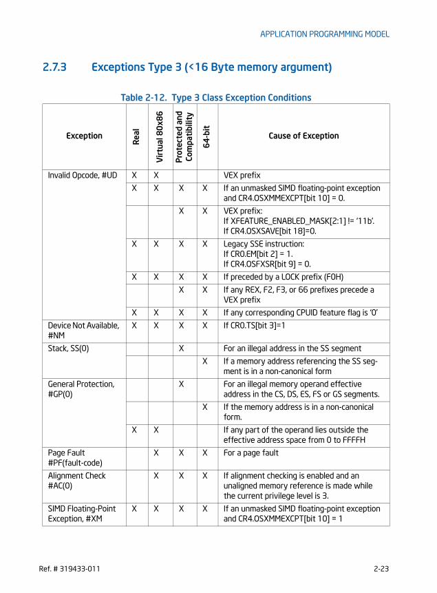
APPLICATION PROGRAMMING MODEL
2.7.3 Exceptions Type 3 (<16 Byte memory argument)
Table 2-12. Type 3 Class Exception Conditions
ExceptionR
eal
Vir
tual
80
x86
Prot
ecte
d an
d Co
mpa
tibi
lity
64
-bit
Cause of Exception
Invalid Opcode, #UD X X VEX prefix
X X X X If an unmasked SIMD floating-point exception and CR4.OSXMMEXCPT[bit 10] = 0.
X X VEX prefix:If XFEATURE_ENABLED_MASK[2:1] != ‘11b’.If CR4.OSXSAVE[bit 18]=0.
X X X X Legacy SSE instruction:If CR0.EM[bit 2] = 1.If CR4.OSFXSR[bit 9] = 0.
X X X X If preceded by a LOCK prefix (F0H)
X X If any REX, F2, F3, or 66 prefixes precede a VEX prefix
X X X X If any corresponding CPUID feature flag is ‘0’
Device Not Available, #NM
X X X X If CR0.TS[bit 3]=1
Stack, SS(0) X For an illegal address in the SS segment
X If a memory address referencing the SS seg-ment is in a non-canonical form
General Protection, #GP(0)
X For an illegal memory operand effective address in the CS, DS, ES, FS or GS segments.
X If the memory address is in a non-canonical form.
X X If any part of the operand lies outside the effective address space from 0 to FFFFH
Page Fault #PF(fault-code)
X X X For a page fault
Alignment Check #AC(0)
X X X If alignment checking is enabled and an unaligned memory reference is made while the current privilege level is 3.
SIMD Floating-Point Exception, #XM
X X X X If an unmasked SIMD floating-point exception and CR4.OSXMMEXCPT[bit 10] = 1
Ref. # 319433-011 2-23
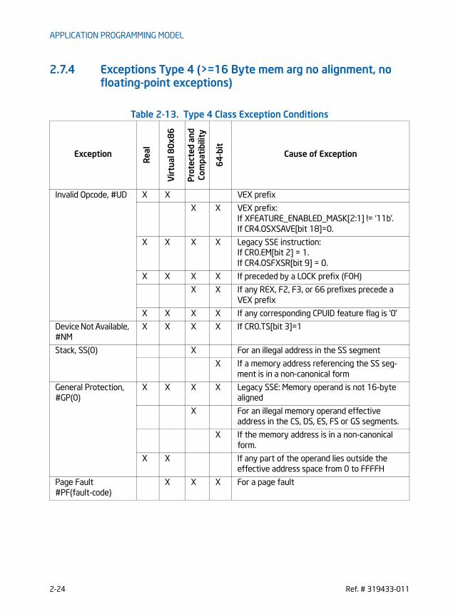
APPLICATION PROGRAMMING MODEL
2.7.4 Exceptions Type 4 (>=16 Byte mem arg no alignment, no floating-point exceptions)
Table 2-13. Type 4 Class Exception Conditions
ExceptionR
eal
Vir
tual
80
x86
Pro
tect
ed a
nd
Com
pati
bilit
y
64
-bit
Cause of Exception
Invalid Opcode, #UD X X VEX prefix
X X VEX prefix:If XFEATURE_ENABLED_MASK[2:1] != ‘11b’.If CR4.OSXSAVE[bit 18]=0.
X X X X Legacy SSE instruction:If CR0.EM[bit 2] = 1.If CR4.OSFXSR[bit 9] = 0.
X X X X If preceded by a LOCK prefix (F0H)
X X If any REX, F2, F3, or 66 prefixes precede a VEX prefix
X X X X If any corresponding CPUID feature flag is ‘0’
Device Not Available, #NM
X X X X If CR0.TS[bit 3]=1
Stack, SS(0) X For an illegal address in the SS segment
X If a memory address referencing the SS seg-ment is in a non-canonical form
General Protection, #GP(0)
X X X X Legacy SSE: Memory operand is not 16-byte aligned
X For an illegal memory operand effective address in the CS, DS, ES, FS or GS segments.
X If the memory address is in a non-canonical form.
X X If any part of the operand lies outside the effective address space from 0 to FFFFH
Page Fault #PF(fault-code)
X X X For a page fault
2-24 Ref. # 319433-011

APPLICATION PROGRAMMING MODEL
2.7.5 Exceptions Type 5 (<16 Byte mem arg and no FP exceptions)
Table 2-14. Type 5 Class Exception Conditions
ExceptionR
eal
Vir
tual
80
x86
Prot
ecte
d an
d Co
mpa
tibi
lity
64
-bit
Cause of Exception
Invalid Opcode, #UD X X VEX prefix
X X VEX prefix:If XFEATURE_ENABLED_MASK[2:1] != ‘11b’.If CR4.OSXSAVE[bit 18]=0.
X X X X Legacy SSE instruction:If CR0.EM[bit 2] = 1.If CR4.OSFXSR[bit 9] = 0.
X X X X If preceded by a LOCK prefix (F0H)
X X If any REX, F2, F3, or 66 prefixes precede a VEX prefix
X X X X If any corresponding CPUID feature flag is ‘0’
Device Not Available, #NM
X X X X If CR0.TS[bit 3]=1
Stack, SS(0) X For an illegal address in the SS segment
X If a memory address referencing the SS seg-ment is in a non-canonical form
General Protection, #GP(0)
X For an illegal memory operand effective address in the CS, DS, ES, FS or GS segments.
X If the memory address is in a non-canonical form.
X X If any part of the operand lies outside the effective address space from 0 to FFFFH
Page Fault #PF(fault-code)
X X X For a page fault
Alignment Check #AC(0)
X X X If alignment checking is enabled and an unaligned memory reference is made while the current privilege level is 3.
Ref. # 319433-011 2-25

APPLICATION PROGRAMMING MODEL
2.7.6 Exceptions Type 6 (VEX-Encoded Instructions Without Legacy SSE Analogues)
Note: At present, the AVX instructions in this category do not generate floating-point exceptions.
Table 2-15. Type 6 Class Exception Conditions
Exception
Rea
l
Vir
tual
80
x86
Pro
tect
ed a
nd
Com
pati
bilit
y
64
-bit
Cause of Exception
Invalid Opcode, #UD X X VEX prefix
X X If XFEATURE_ENABLED_MASK[2:1] != ‘11b’.If CR4.OSXSAVE[bit 18]=0.
X X If preceded by a LOCK prefix (F0H)
X X If any REX, F2, F3, or 66 prefixes precede a VEX prefix
X X If any corresponding CPUID feature flag is ‘0’
Device Not Available, #NM
X X If CR0.TS[bit 3]=1
Stack, SS(0) X For an illegal address in the SS segment
X If a memory address referencing the SS seg-ment is in a non-canonical form
General Protection, #GP(0)
X For an illegal memory operand effective address in the CS, DS, ES, FS or GS segments.
X If the memory address is in a non-canonical form.
Page Fault #PF(fault-code)
X X For a page fault
Alignment Check #AC(0)
X X For 4 or 8 byte memory references if align-ment checking is enabled and an unaligned memory reference is made while the current privilege level is 3.
2-26 Ref. # 319433-011

APPLICATION PROGRAMMING MODEL
2.7.7 Exceptions Type 7 (No FP exceptions, no memory arg)
Table 2-16. Type 7 Class Exception Conditions
2.7.8 Exceptions Type 8 (AVX and no memory argument)
Table 2-17. Type 8 Class Exception Conditions
ExceptionR
eal
Vir
tual
80
x86
Prot
ecte
d an
d Co
mpa
tibi
lity
64
-bit
Cause of Exception
Invalid Opcode, #UD X X VEX prefix
X X VEX prefix:If XFEATURE_ENABLED_MASK[2:1] != ‘11b’.If CR4.OSXSAVE[bit 18]=0.
X X X X Legacy SSE instruction:If CR0.EM[bit 2] = 1.If CR4.OSFXSR[bit 9] = 0.
X X X X If preceded by a LOCK prefix (F0H)
X X If any REX, F2, F3, or 66 prefixes precede a VEX prefix
X X X X If any corresponding CPUID feature flag is ‘0’
Device Not Available, #NM
X X If CR0.TS[bit 3]=1
Exception
Rea
l
Vir
tual
80x
86
Pro
tect
ed a
nd
Com
patib
ility
64-b
it
Cause of Exception
Invalid Opcode, #UD X X Always in Real or Virtual 80x86 mode
X X If XFEATURE_ENABLED_MASK[2:1] != ‘11b’.If CR4.OSXSAVE[bit 18]=0.If CPUID.01H.ECX.AVX[bit 28]=0.If VEX.vvvv != 1111B.
X X X X If proceeded by a LOCK prefix (F0H)
Device Not Available, #NM
X X If CR0.TS[bit 3]=1.
Ref. # 319433-011 2-27

APPLICATION PROGRAMMING MODEL
2.7.9 Exception Type 11 (VEX-only, mem arg no AC, floating-point exceptions)
Table 2-18. Type 11 Class Exception Conditions
ExceptionR
eal
Vir
tual
80
x86
Pro
tect
ed a
nd
Com
pati
bilit
y
64
-bit
Cause of Exception
Invalid Opcode, #UD X X VEX prefix
X X VEX prefix:If XFEATURE_ENABLED_MASK[2:1] != ‘11b’.If CR4.OSXSAVE[bit 18]=0.
X X X X If preceded by a LOCK prefix (F0H)
X X If any REX, F2, F3, or 66 prefixes precede a VEX prefix
X X X X If any corresponding CPUID feature flag is ‘0’
Device Not Available, #NM
X X X X If CR0.TS[bit 3]=1
Stack, SS(0) X For an illegal address in the SS segment
X If a memory address referencing the SS seg-ment is in a non-canonical form
General Protection, #GP(0)
X For an illegal memory operand effective address in the CS, DS, ES, FS or GS segments.
X If the memory address is in a non-canonical form.
X X If any part of the operand lies outside the effective address space from 0 to FFFFH
Page Fault #PF(fault-code)
X X X For a page fault
SIMD Floating-Point Exception, #XM
X X X X If an unmasked SIMD floating-point exception and CR4.OSXMMEXCPT[bit 10] = 1
2-28 Ref. # 319433-011

APPLICATION PROGRAMMING MODEL
2.7.10 Exception Type 12 (VEX-only, VSIB mem arg, no AC, no floating-point exceptions)
Table 2-19. Type 12 Class Exception Conditions
ExceptionR
eal
Vir
tual
80
x86
Pro
tect
ed a
nd
Com
pati
bilit
y
64
-bit
Cause of Exception
Invalid Opcode, #UD X X VEX prefix
X X VEX prefix:If XFEATURE_ENABLED_MASK[2:1] != ‘11b’.If CR4.OSXSAVE[bit 18]=0.
X X X X If preceded by a LOCK prefix (F0H)
X X If any REX, F2, F3, or 66 prefixes precede a VEX prefix
X X X NA If address size attribute is 16 bit
X X X X If ModR/M.mod = ‘11b’
X X X X If ModR/M.rm != ‘100b’
X X X X If any corresponding CPUID feature flag is ‘0’
X X X X If any vector register is used more than once between the destination register, mask regis-ter and the index register in VSIB addressing.
Device Not Available, #NM
X X X X If CR0.TS[bit 3]=1
Stack, SS(0) X For an illegal address in the SS segment
X If a memory address referencing the SS seg-ment is in a non-canonical form
General Protection, #GP(0)
X For an illegal memory operand effective address in the CS, DS, ES, FS or GS segments.
X If the memory address is in a non-canonical form.
X X If any part of the operand lies outside the effective address space from 0 to FFFFH
Page Fault #PF(fault-code)
X X X For a page fault
Ref. # 319433-011 2-29

APPLICATION PROGRAMMING MODEL
2.7.11 Exception Conditions for VEX-Encoded GPR InstructionsThe exception conditions applicable to VEX-encoded GPR instruction differs from those of legacy GPR instructions. Table 2-20 groups instructions listed in Chapter 7 and lists details of the exception conditions for VEX-encoded GRP instructions in Table 2-22 for those instructions which have a default operand size of 32 bits and 16-bit operand size is not encodable. Table 2-21 lists exception conditions for those instructions that support operation on 16-bit operands.
(*) - Additional exception restrictions are present - see the Instruction description for details
Table 2-20. Exception Groupings for Instructions Listed in Chapter 7
Exception Class Instruction
See Table 2-21 LZCNT, TZCNT
See Table 2-22 ANDN, BLSI, BLSMSK, BLSR, BZHI, MULX, PDEP, PEXT, RORX, SARX, SHLX, SHRX
Table 2-21. Exception Definition for LZCNT and TZCNT
Exception
Rea
l
Vir
tual
80
x86
Prot
ecte
d an
d Co
mpa
tibi
lity
64
-bit
Cause of Exception
Stack, SS(0) X X X For an illegal address in the SS segment
X If a memory address referencing the SS seg-ment is in a non-canonical form
General Protection, #GP(0)
X For an illegal memory operand effective address in the CS, DS, ES, FS or GS segments. If the DS, ES, FS, or GS register is used to access memory and it contains a null segment selector.
X If the memory address is in a non-canonical form.
X X If any part of the operand lies outside the effective address space from 0 to FFFFH
Page Fault #PF(fault-code)
X X X For a page fault
Alignment Check #AC(0)
X X X If alignment checking is enabled and an unaligned memory reference is made while the current privilege level is 3.
2-30 Ref. # 319433-011

APPLICATION PROGRAMMING MODEL
2.8 PROGRAMMING CONSIDERATIONS WITH 128-BIT SIMD INSTRUCTIONS
VEX-encoded SIMD instructions generally operate on the 256-bit YMM register state. In contrast, non-VEX encoded instructions (e.g from SSE to AES) operating on XMM registers only access the lower 128-bit of YMM registers. Processors supporting both 256-bit VEX-encoded instructions and legacy 128-bit SIMD instructions have internal state to manage the upper and lower halves of the YMM register states. Functionally, VEX-encoded SIMD instructions can be intermixed with legacy SSE instructions (non-VEX-encoded SIMD instructions operating on XMM registers). However, there is a
Table 2-22. Exception Definition (VEX-Encoded GPR Instructions)
Exception
Rea
l
Vir
tual
80
x86
Prot
ecte
d an
d Co
mpa
tibi
lity
64
-bit
Cause of Exception
Invalid Opcode, #UD X X X X If BMI1/BMI2 CPUID feature flag is ‘0’
X X If a VEX prefix is present
X X If any REX, F2, F3, or 66 prefixes precede a VEX prefix
Stack, SS(0) X X X For an illegal address in the SS segment
X If a memory address referencing the SS seg-ment is in a non-canonical form
General Protection, #GP(0)
X For an illegal memory operand effective address in the CS, DS, ES, FS or GS segments. If the DS, ES, FS, or GS register is used to access memory and it contains a null segment selector.
X If the memory address is in a non-canonical form.
X X If any part of the operand lies outside the effective address space from 0 to FFFFH
Page Fault #PF(fault-code)
X X X For a page fault
Alignment Check #AC(0)
X X X If alignment checking is enabled and an unaligned memory reference is made while the current privilege level is 3.
Ref. # 319433-011 2-31

APPLICATION PROGRAMMING MODEL
performance impact with intermixing VEX-encoded SIMD instructions (AVX, FMA) and Legacy SSE instructions that only operate on the XMM register state. The general programming considerations to realize optimal performance are the following:• Minimize transition delays and partial register stalls with YMM registers accesses:
Intermixed 256-bit, 128-bit or scalar SIMD instructions that are encoded with VEX prefixes have no transition delay due to internal state management. Sequences of legacy SSE instructions (including SSE2, and subsequentgenerations non-VEX-encoded SIMD extensions) that are not intermixed withVEX-encoded SIMD instructions are not subject to transition delays.
• When an application must employ AVX and/or FMA, along with legacy SSE code, it should minimize the number of transitions between VEX-encoded instructions and legacy, non-VEX-encoded SSE code. Section 2.8.1 provides recommendation for software to minimize the impact of transitions between VEX-encoded code and legacy SSE code.
In addition to performance considerations, programmers should also be cognizant of the implications of VEX-encoded AVX instructions with the expectations of system software components that manage the processor state components enabled by XCR0. For additional information see Section 4.1.9.1, “Vector Length Transition and Programming Considerations”.
2.8.1 Clearing Upper YMM State Between AVX and Legacy SSE Instructions
There is no transition penalty if an application clears the upper bits of all YMM regis-ters (set to ‘0’) via VZEROUPPER, VZEROALL, before transitioning between AVX instructions and legacy SSE instructions. Note: clearing the upper state via sequences of XORPS or loading ‘0’ values individually may be useful for breaking dependency, but will not avoid state transition penalties.
Example 1: an application using 256-bit AVX instructions makes calls to a library written using Legacy SSE instructions. This would encounter a delay upon executing the first Legacy SSE instruction in that library and then (after exiting the library) upon executing the first AVX instruction. To eliminate both of these delays, the user should execute the instruction VZEROUPPER prior to entering the legacy library and (after exiting the library) before executing in a 256-bit AVX code path.
Example 2: a library using 256-bit AVX instructions is intended to support other applications that use legacy SSE instructions. Such a library function should execute VZEROUPPER prior to executing other VEX-encoded instructions. The library function should issue VZEROUPPER at the end of the function before it returns to the calling application. This will prevent the calling application to experience delay when it starts to execute legacy SSE code.
2-32 Ref. # 319433-011

APPLICATION PROGRAMMING MODEL
2.8.2 Using AVX 128-bit Instructions Instead of Legacy SSE instructions
Applications using AVX and FMA should migrate legacy 128-bit SIMD instructions to their 128-bit AVX equivalents. AVX supplies the full complement of 128-bit SIMD instructions except for AES and PCLMULQDQ.
2.8.3 Unaligned Memory Access and Buffer Size ManagementThe majority of AVX instructions support loading 16/32 bytes from memory without alignment restrictions (A number non-VEX-encoded SIMD instructions also don’t require 16-byte address alignment, e.g. MOVDQU, MOVUPS, MOVUPD, LDDQU, PCMPESTRI, PCMPESTRM, PCMPISTRI and PCMPISTRM). A buffer size management issue related to unaligned SIMD memory access is discussed here.The size requirements for memory buffer allocation should consider unaligned SIMD memory semantics and application usage. Frequently a caller function may pass an address pointer in conjunction with a length parameter. From the caller perspective, the length parameter usually corresponds to the limit of the allocated memory buffer range, or it may correspond to certain application-specific configuration parameter that have indirect relationship with valid buffer size. For certain types of application usage, it may be desirable to make distinctions between valid buffer range limit versus other application specific parameters related memory access patterns, examples of the latter may be stride distance, frame dimensions, etc. There may be situations that a callee wishes to load 16-bytes of data with parts of the 16-bytes lying outside the valid memory buffer region to take advantage of the efficiency of SIMD load bandwidth and discard invalid data elements outside the buffer boundary. An example of this may be in video processing of frames having dimensions that are not modular 16 bytes. Allocating buffers without regard to the use of the subsequent 16/32 bytes can lead to the rare occurrence of access rights violation as described below:• A present page in the linear address space being used by ring 3 code is followed
by a page owned by ring 0 code,• A caller routine allocates a memory buffer without adding extra pad space and
passes the buffer address to a callee routine,• A callee routine implements an iterative processing algorithm by advancing an
address pointer relative to the buffer address using SIMD instructions with unaligned 16/32 load semantics
• The callee routine may choose to load 16/32 bytes near buffer boundary with the intent to discard invalid data outside the data buffer allocated by the caller.
• If the valid data buffer extends to the end of the present page, unaligned 16/32 byte loads near the end of a present page may spill over to the subsequent ring-0 page and causing a #GP.
Ref. # 319433-011 2-33

APPLICATION PROGRAMMING MODEL
This can be avoided by padding each individual allocation or by padding each area memory is allocated from. As a general rule, the minimal padding size should be the width the largest SIMD register that might be used in conjunction with unaligned SIMD memory access.
2.9 CPUID INSTRUCTION
CPUID—CPU Identification
Description
The ID flag (bit 21) in the EFLAGS register indicates support for the CPUID instruc-tion. If a software procedure can set and clear this flag, the processor executing the procedure supports the CPUID instruction. This instruction operates the same in non-64-bit modes and 64-bit mode.
CPUID returns processor identification and feature information in the EAX, EBX, ECX, and EDX registers.1 The instruction’s output is dependent on the contents of the EAX register upon execution (in some cases, ECX as well). For example, the following pseudocode loads EAX with 00H and causes CPUID to return a Maximum Return Value and the Vendor Identification String in the appropriate registers:
MOV EAX, 00HCPUID
Table 2-23 shows information returned, depending on the initial value loaded into the EAX register. Table 2-24 shows the maximum CPUID input value recognized for each family of IA-32 processors on which CPUID is implemented.
Two types of information are returned: basic and extended function information. If a value is entered for CPUID.EAX is invalid for a particular processor, the data for the highest basic information leaf is returned. For example, using the Intel Core 2 Duo E6850 processor, the following is true:
CPUID.EAX = 05H (* Returns MONITOR/MWAIT leaf. *)
Opcode Instruction 64-Bit ModeCompat/Leg Mode
Description
0F A2 CPUID Valid Valid Returns processor identification and feature information to the EAX, EBX, ECX, and EDX registers, as determined by input entered in EAX (in some cases, ECX as well).
1. On Intel 64 processors, CPUID clears the high 32 bits of the RAX/RBX/RCX/RDX registers in all modes.
2-34 Ref. # 319433-011

APPLICATION PROGRAMMING MODEL
CPUID.EAX = 0AH (* Returns Architectural Performance Monitoring leaf. *) CPUID.EAX = 0BH (* INVALID: Returns the same information as CPUID.EAX = 0AH. *) CPUID.EAX = 80000008H (* Returns virtual/physical address size data. *)CPUID.EAX = 8000000AH (* INVALID: Returns same information as CPUID.EAX = 0AH. *)
When CPUID returns the highest basic leaf information as a result of an invalid input EAX value, any dependence on input ECX value in the basic leaf is honored.
CPUID can be executed at any privilege level to serialize instruction execution. Seri-alizing instruction execution guarantees that any modifications to flags, registers, and memory for previous instructions are completed before the next instruction is fetched and executed.
See also:
“Serializing Instructions” in Chapter 8, “Multiple-Processor Management,” in the Intel® 64 and IA-32 Architectures Software Developer’s Manual, Volume 3A
"Caching Translation Information" in Chapter 4, “Paging,” in the Intel® 64 and IA-32 Architectures Software Developer’s Manual, Volume 3A
Table 2-23. Information Returned by CPUID Instruction
Initial EAX Value Information Provided about the Processor
Basic CPUID Information
0H EAXEBXECXEDX
Maximum Input Value for Basic CPUID Information (see Table 2-24)“Genu”“ntel”“ineI”
01H EAX
EBX
ECXEDX
Version Information: Type, Family, Model, and Stepping ID (see Figure 2-2)
Bits 7-0: Brand IndexBits 15-8: CLFLUSH line size (Value ∗ 8 = cache line size in bytes)Bits 23-16: Maximum number of addressable IDs for logical processors in this physical package*. Bits 31-24: Initial APIC ID
Feature Information (see Figure 2-3 and Table 2-26)Feature Information (see Figure 2-4 and Table 2-27)NOTES: * The nearest power-of-2 integer that is not smaller than EBX[23:16] is the maximum number of unique initial APIC IDs reserved for address-ing different logical processors in a physical package.
02H EAXEBXECXEDX
Cache and TLB Information (see Table 2-28)Cache and TLB InformationCache and TLB InformationCache and TLB Information
Ref. # 319433-011 2-35

APPLICATION PROGRAMMING MODEL
03H EAX Reserved.
EBX Reserved.
ECX Bits 00-31 of 96 bit processor serial number. (Available in Pentium III processor only; otherwise, the value in this register is reserved.)
EDX Bits 32-63 of 96 bit processor serial number. (Available in Pentium III processor only; otherwise, the value in this register is reserved.)
NOTES: Processor serial number (PSN) is not supported in the Pentium 4 pro-cessor or later. On all models, use the PSN flag (returned usingCPUID) to check for PSN support before accessing the feature.
See AP-485, Intel Processor Identification and the CPUID Instruc-tion (Order Number 241618) for more information on PSN.
CPUID leaves > 3 < 80000000 are visible only when IA32_MISC_ENABLES.BOOT_NT4[bit 22] = 0 (default).
Deterministic Cache Parameters Leaf
04H NOTES:Leaf 04H output depends on the initial value in ECX. See also: “INPUT EAX = 4: Returns Deterministic Cache Parametersfor each level on page 2-58.
EAX Bits 4-0: Cache Type Field0 = Null - No more caches1 = Data Cache 2 = Instruction Cache3 = Unified Cache4-31 = Reserved
Bits 7-5: Cache Level (starts at 1) Bits 8: Self Initializing cache level (does not need SW initialization)Bits 9: Fully Associative cache
Bits 13-10: ReservedBits 25-14: Maximum number of addressable IDs for logical processors sharing this cache*, ** Bits 31-26: Maximum number of addressable IDs for processor cores in the physical package*, ***, ****
EBX Bits 11-00: L = System Coherency Line Size*Bits 21-12: P = Physical Line partitions*Bits 31-22: W = Ways of associativity*
ECX Bits 31-00: S = Number of Sets*
Table 2-23. Information Returned by CPUID Instruction(Continued)
Initial EAX Value Information Provided about the Processor
2-36 Ref. # 319433-011

APPLICATION PROGRAMMING MODEL
EDX Bit 0: WBINVD/INVD behavior on lower level cachesBit 10: Write-Back Invalidate/Invalidate
0 = WBINVD/INVD from threads sharing this cache acts upon lower level caches for threads sharing this cache1 = WBINVD/INVD is not guaranteed to act upon lower level caches of non-originating threads sharing this cache.
Bit 1: Cache Inclusiveness0 = Cache is not inclusive of lower cache levels.1 = Cache is inclusive of lower cache levels.
Bit 2: Complex cache indexing0 = Direct mapped cache1 = A complex function is used to index the cache, potentially usingall address bits.
Bits 31-03: Reserved = 0
NOTES:* Add one to the return value to get the result. ** The nearest power-of-2 integer that is not smaller than (1 +
EAX[25:14]) is the number of unique initial APIC IDs reserved foraddressing different logical processors sharing this cache
*** The nearest power-of-2 integer that is not smaller than (1 +EAX[31:26]) is the number of unique Core_IDs reserved for address-ing different processor cores in a physical package. Core ID is a sub-set of bits of the initial APIC ID.
****The returned value is constant for valid initial values in ECX. ValidECX values start from 0.
MONITOR/MWAIT Leaf
05H EAX Bits 15-00: Smallest monitor-line size in bytes (default is processor's monitor granularity) Bits 31-16: Reserved = 0
EBX Bits 15-00: Largest monitor-line size in bytes (default is processor's monitor granularity) Bits 31-16: Reserved = 0
ECX Bits 00: Enumeration of Monitor-Mwait extensions (beyond EAX and EBX registers) supported
Bits 01: Supports treating interrupts as break-event for MWAIT, even when interrupts disabled
Bits 31 - 02: Reserved
Table 2-23. Information Returned by CPUID Instruction(Continued)
Initial EAX Value Information Provided about the Processor
Ref. # 319433-011 2-37

APPLICATION PROGRAMMING MODEL
EDX Bits 03 - 00: Number of C0* sub C-states supported using MWaitBits 07 - 04: Number of C1* sub C-states supported using MWAITBits 11 - 08: Number of C2* sub C-states supported using MWAITBits 15 - 12: Number of C3* sub C-states supported using MWAITBits 19 - 16: Number of C4* sub C-states supported using MWAITBits 31 - 20: Reserved = 0NOTE:* The definition of C0 through C4 states for MWAIT extension are pro-
cessor-specific C-states, not ACPI C-states.
Thermal and Power Management Leaf
06H EAX
EBX
Bits 00: Digital temperature sensor is supported if setBits 01: Intel Turbo Boost Technology is availableBits 31 - 02: Reserved Bits 03 - 00: Number of Interrupt Thresholds in Digital Thermal SensorBits 31 - 04: Reserved
ECX Bits 00: Hardware Coordination Feedback Capability (Presence of MCNT and ACNT MSRs). The capability to provide a measure of delivered pro-cessor performance (since last reset of the counters), as a percentage of expected processor performance at frequency specified in CPUID Brand StringBits 02 - 01: Reserved = 0Bit 03: The processor supports performance-energy bias preference ifCPUID.06H:ECX.SETBH[bit 3] is set and it also implies the presence of anew architectural MSR called IA32_ENERGY_PERF_BIAS (1B0H)Bits 31 - 04: Reserved = 0
EDX Reserved = 0
Structured Extended feature Leaf
07H NOTES:Leaf 07H main leaf (ECX = 0). IF leaf 07H is not supported, EAX=EBX=ECX=EDX=0
EAX Bits 31-0: Reports the maximum number sub-leaves that are sup-ported in leaf 07H.
Table 2-23. Information Returned by CPUID Instruction(Continued)
Initial EAX Value Information Provided about the Processor
2-38 Ref. # 319433-011

APPLICATION PROGRAMMING MODEL
EBX Bits 00: FSGSBASEBits 02-01: Reserved.Bits 03: BMI1Bits 04: Reserved.Bits 05: AVX2Bits 07-06: Reserved.Bits 08: BMI2Bits 09: ERMSBits 10: INVPCIDBits 31-11: Reserved.
ECX Bit 31-0: Reserved
EDX Bit 31-0: Reserved.
Structured Extended Feature Enumeration Sub-leaves (EAX = 07H, ECX = n, n > 1)
07H NOTES:Leaf 07H output depends on the initial value in ECX. If ECX contains an invalid sub leaf index, EAX/EBX/ECX/EDX return 0.
EAX This field reports 0 if the sub-leaf index, n, is invalid*; otherwise it is reserved.
EBX This field reports 0 if the sub-leaf index, n, is invalid*; otherwise it is reserved.
ECX This field reports 0 if the sub-leaf index, n, is invalid*; otherwise it is reserved.
EDX This field reports 0 if the sub-leaf index, n, is invalid*; otherwise it is reserved.
Direct Cache Access Information Leaf
09H EAXEBXECXEDX
Value of bits [31:0] of IA32_PLATFORM_DCA_CAP MSR (address 1F8H)Reserved Reserved Reserved
Architectural Performance Monitoring Leaf
0AH EAX Bits 07 - 00: Version ID of architectural performance monitoringBits 15- 08: Number of general-purpose performance monitoring counter per logical processorBits 23 - 16: Bit width of general-purpose, performance monitoring counter Bits 31 - 24: Length of EBX bit vector to enumerate architectural per-formance monitoring events
Table 2-23. Information Returned by CPUID Instruction(Continued)
Initial EAX Value Information Provided about the Processor
Ref. # 319433-011 2-39

APPLICATION PROGRAMMING MODEL
EBX Bit 00: Core cycle event not available if 1Bit 01: Instruction retired event not available if 1Bit 02: Reference cycles event not available if 1Bit 03: Last-level cache reference event not available if 1Bit 04: Last-level cache misses event not available if 1Bit 05: Branch instruction retired event not available if 1Bit 06: Branch mispredict retired event not available if 1Bits 31- 07: Reserved = 0
ECX
EDX
Reserved = 0Bits 04 - 00: Number of fixed-function performance counters (if Ver-sion ID > 1)Bits 12- 05: Bit width of fixed-function performance counters (if Ver-sion ID > 1)Reserved = 0
Extended Topology Enumeration Leaf
0BH NOTES:Most of Leaf 0BH output depends on the initial value in ECX. EDX output do not vary with initial value in ECX.ECX[7:0] output always reflect initial value in ECX.All other output value for an invalid initial value in ECX are 0This leaf exists if EBX[15:0] contain a non-zero value.
EAX Bits 04-00: Number of bits to shift right on x2APIC ID to get a unique topology ID of the next level type*. All logical processors with the same next level ID share current level.Bits 31-5: Reserved.
EBX Bits 15 - 00: Number of logical processors at this level type. The num-ber reflects configuration as shipped by Intel**.Bits 31- 16: Reserved.
ECX Bits 07 - 00: Level number. Same value in ECX inputBits 15 - 08: Level type***.Bits 31 - 16: Reserved.
EDX Bits 31- 0: x2APIC ID the current logical processor.
NOTES:* Software should use this field (EAX[4:0]) to enumerate processor topology of the system.
Table 2-23. Information Returned by CPUID Instruction(Continued)
Initial EAX Value Information Provided about the Processor
2-40 Ref. # 319433-011

APPLICATION PROGRAMMING MODEL
** Software must not use EBX[15:0] to enumerate processor topology of the system. This value in this field (EBX[15:0]) is only intended for display/diagnostic purposes. The actual number of logical processors available to BIOS/OS/Applications may be different from the value of EBX[15:0], depending on software and platform hardware configura-tions.
*** The value of the “level type” field is not related to level numbers in any way, higher “level type” values do not mean higher levels. Level type field has the following encoding:0: invalid1: SMT2: Core3-255: Reserved
Processor Extended State Enumeration Main Leaf (EAX = 0DH, ECX = 0)
0DH NOTES:Leaf 0DH main leaf (ECX = 0).
EAX Bits 31-00: Reports the valid bit fields of the lower 32 bits of the XFEATURE_ENABLED_MASK register. If a bit is 0, the corresponding bit field in XFEATURE_ENABLED_MASK is reserved.Bit 00: legacy x87 Bit 01: 128-bit SSEBit 02: 256-bit AVX
EBX Bits 31-00: Maximum size (bytes, from the beginning of the XSAVE/XRSTOR save area) required by enabled features in XCR0. May be different than ECX if some features at the end of the XSAVE save area are not enabled.
ECX Bit 31-00: Maximum size (bytes, from the beginning of the XSAVE/XRSTOR save area) of the XSAVE/XRSTOR save area required by all supported features in the processor, i.e all the valid bit fields in XCR0.
EDX Bit 31-0: Reports the valid bit fields of the upper 32 bits of the XFEATURE_ENABLED_MASK register (XCR0). If a bit is 0, the corre-sponding bit field in XCR0 is reserved
Processor Extended State Enumeration Sub-leaf (EAX = 0DH, ECX = 1)
Table 2-23. Information Returned by CPUID Instruction(Continued)
Initial EAX Value Information Provided about the Processor
Ref. # 319433-011 2-41

APPLICATION PROGRAMMING MODEL
EAX
EBXECXEDX
Bit 00: XSAVEOPT is available;Bits 31-1: ReservedReservedReservedReserved
Processor Extended State Enumeration Sub-leaves (EAX = 0DH, ECX = n, n > 1)
0DH NOTES:Leaf 0DH output depends on the initial value in ECX. If ECX contains an invalid sub leaf index, EAX/EBX/ECX/EDX return 0.Each valid sub-leaf index maps to a valid bit in the XCR0 register starting at bit position 2
EAX Bits 31-0: The size in bytes (from the offset specified in EBX) of the save area for an extended state feature associated with a valid sub-leaf index, n. This field reports 0 if the sub-leaf index, n, is invalid*.
EBX Bits 31-0: The offset in bytes of this extended state component’s save area from the beginning of the XSAVE/XRSTOR area.This field reports 0 if the sub-leaf index, n, is invalid*.
ECX This field reports 0 if the sub-leaf index, n, is invalid*; otherwise it is reserved.
EDX This field reports 0 if the sub-leaf index, n, is invalid*; otherwise it is reserved.
*The highest valid sub-leaf index, n, is (POPCNT(CPUID.(EAX=0D, ECX=0):EAX) + POPCNT(CPUID.(EAX=0D, ECX=0):EDX) - 1)
Extended Function CPUID Information
80000000H EAX Maximum Input Value for Extended Function CPUID Information (see Table 2-24).
EBXECXEDX
ReservedReservedReserved
80000001H EAXEBXECX
Extended Processor Signature and Feature Bits.ReservedBit 0: LAHF/SAHF available in 64-bit modeBits 31-1 Reserved
Table 2-23. Information Returned by CPUID Instruction(Continued)
Initial EAX Value Information Provided about the Processor
2-42 Ref. # 319433-011

APPLICATION PROGRAMMING MODEL
EDX Bits 4-0: ReservedBit 5: LZCNT availableBits 10-6: ReservedBit 11: SYSCALL/SYSRET available (when in 64-bit mode)Bits 19-12: Reserved = 0Bit 20: Execute Disable Bit availableBits 28-21: Reserved = 0Bit 29: Intel® 64 Architecture available if 1Bits 31-30: Reserved = 0
80000002H EAXEBXECXEDX
Processor Brand StringProcessor Brand String ContinuedProcessor Brand String ContinuedProcessor Brand String Continued
80000003H EAXEBXECXEDX
Processor Brand String ContinuedProcessor Brand String ContinuedProcessor Brand String ContinuedProcessor Brand String Continued
80000004H EAXEBXECXEDX
Processor Brand String ContinuedProcessor Brand String ContinuedProcessor Brand String ContinuedProcessor Brand String Continued
80000005H EAXEBXECXEDX
Reserved = 0Reserved = 0Reserved = 0Reserved = 0
80000006H EAXEBX
Reserved = 0Reserved = 0
ECX
EDX
Bits 7-0: Cache Line size in bytesBits 15-12: L2 Associativity field *Bits 31-16: Cache size in 1K unitsReserved = 0
NOTES:* L2 associativity field encodings:
00H - Disabled01H - Direct mapped02H - 2-way04H - 4-way06H - 8-way08H - 16-way0FH - Fully associative
Table 2-23. Information Returned by CPUID Instruction(Continued)
Initial EAX Value Information Provided about the Processor
Ref. # 319433-011 2-43

APPLICATION PROGRAMMING MODEL
INPUT EAX = 0: Returns CPUID’s Highest Value for Basic Processor Information and the Vendor Identification String
When CPUID executes with EAX set to 0, the processor returns the highest value the CPUID recognizes for returning basic processor information. The value is returned in the EAX register (see Table 2-24) and is processor specific.
A vendor identification string is also returned in EBX, EDX, and ECX. For Intel processors, the string is “GenuineIntel” and is expressed:
EBX ← 756e6547h (* "Genu", with G in the low 4 bits of BL *)EDX ← 49656e69h (* "ineI", with i in the low 4 bits of DL *)ECX ← 6c65746eh (* "ntel", with n in the low 4 bits of CL *)
INPUT EAX = 80000000H: Returns CPUID’s Highest Value for Extended Processor Information
When CPUID executes with EAX set to 0, the processor returns the highest value the processor recognizes for returning extended processor information. The value is returned in the EAX register (see Table 2-24) and is processor specific.
80000007H EAXEBXECXEDX
Reserved = 0Reserved = 0Reserved = 0Reserved = 0
80000008H EAX Virtual/Physical Address size Bits 7-0: #Physical Address Bits*Bits 15-8: #Virtual Address BitsBits 31-16: Reserved = 0
EBXECXEDX
Reserved = 0Reserved = 0Reserved = 0
NOTES:* If CPUID.80000008H:EAX[7:0] is supported, the maximum physical
address number supported should come from this field.
Table 2-23. Information Returned by CPUID Instruction(Continued)
Initial EAX Value Information Provided about the Processor
2-44 Ref. # 319433-011

APPLICATION PROGRAMMING MODEL
IA32_BIOS_SIGN_ID Returns Microcode Update Signature
For processors that support the microcode update facility, the IA32_BIOS_SIGN_ID MSR is loaded with the update signature whenever CPUID executes. The signature is returned in the upper DWORD. For details, see Chapter 10 in the Intel® 64 and IA-32 Architectures Software Developer’s Manual, Volume 3A.
Table 2-24. Highest CPUID Source Operand for Intel 64 and IA-32 Processors
Intel 64 or IA-32 Processors
Highest Value in EAX
Basic InformationExtended Function
Information
Earlier Intel486 Processors CPUID Not Implemented CPUID Not Implemented
Later Intel486 Processors and Pentium Processors
01H Not Implemented
Pentium Pro and Pentium II Processors, Intel® Celeron® Processors
02H Not Implemented
Pentium III Processors 03H Not Implemented
Pentium 4 Processors 02H 80000004H
Intel Xeon Processors 02H 80000004H
Pentium M Processor 02H 80000004H
Pentium 4 Processor supporting Hyper-Threading Technology
05H 80000008H
Pentium D Processor (8xx) 05H 80000008H
Pentium D Processor (9xx) 06H 80000008H
Intel Core Duo Processor 0AH 80000008H
Intel Core 2 Duo Processor 0AH 80000008H
Intel Xeon Processor 3000, 5100, 5300 Series
0AH 80000008H
Intel Xeon Processor 3000, 5100, 5200, 5300, 5400 Series
0AH 80000008H
Intel Core 2 Duo Processor 8000 Series
0DH 80000008H
Intel Xeon Processor 5200, 5400 Series
0AH 80000008H
Ref. # 319433-011 2-45

APPLICATION PROGRAMMING MODEL
INPUT EAX = 1: Returns Model, Family, Stepping Information
When CPUID executes with EAX set to 1, version information is returned in EAX (see Figure 2-2). For example: model, family, and processor type for the Intel Xeon processor 5100 series is as follows:• Model — 1111B• Family — 0101B• Processor Type — 00B
See Table 2-25 for available processor type values. Stepping IDs are provided as needed.
NOTESee "Caching Translation Information" in Chapter 4, “Paging,” in the Intel® 64 and IA-32 Architectures Software Developer’s Manual,
Figure 2-2. Version Information Returned by CPUID in EAX
Table 2-25. Processor Type FieldType Encoding
Original OEM Processor 00B
Intel OverDrive® Processor 01B
Dual processor (not applicable to Intel486 processors)
10B
Intel reserved 11B
OM16525
Processor Type
034781112131415161920272831
EAX
Family (0FH for the Pentium 4 Processor Family)
Model
ExtendedFamily ID
ExtendedModel ID
FamilyID
ModelStepping
ID
Extended Family ID (0)
Extended Model ID (0)
Reserved
2-46 Ref. # 319433-011

APPLICATION PROGRAMMING MODEL
Volume 3A, and Chapter 14 in the Intel® 64 and IA-32 Architectures Software Developer’s Manual, Volume 1, for information on identifying earlier IA-32 processors.
The Extended Family ID needs to be examined only when the Family ID is 0FH. Inte-grate the fields into a display using the following rule:
IF Family_ID ≠ 0FHTHEN Displayed_Family = Family_ID;ELSE Displayed_Family = Extended_Family_ID + Family_ID;(* Right justify and zero-extend 4-bit field. *)
FI;(* Show Display_Family as HEX field. *)
The Extended Model ID needs to be examined only when the Family ID is 06H or 0FH. Integrate the field into a display using the following rule:
IF (Family_ID = 06H or Family_ID = 0FH)THEN Displayed_Model = (Extended_Model_ID << 4) + Model_ID;(* Right justify and zero-extend 4-bit field; display Model_ID as HEX field.*)ELSE Displayed_Model = Model_ID;
FI;(* Show Display_Model as HEX field. *)
INPUT EAX = 1: Returns Additional Information in EBX
When CPUID executes with EAX set to 1, additional information is returned to the EBX register: • Brand index (low byte of EBX) — this number provides an entry into a brand
string table that contains brand strings for IA-32 processors. More information about this field is provided later in this section.
• CLFLUSH instruction cache line size (second byte of EBX) — this number indicates the size of the cache line flushed with CLFLUSH instruction in 8-byte increments. This field was introduced in the Pentium 4 processor.
• Local APIC ID (high byte of EBX) — this number is the 8-bit ID that is assigned to the local APIC on the processor during power up. This field was introduced in the Pentium 4 processor.
INPUT EAX = 1: Returns Feature Information in ECX and EDX
When CPUID executes with EAX set to 1, feature information is returned in ECX and EDX.• Figure 2-3 and Table 2-26 show encodings for ECX.• Figure 2-4 and Table 2-27 show encodings for EDX.
Ref. # 319433-011 2-47

APPLICATION PROGRAMMING MODEL
For all feature flags, a 1 indicates that the feature is supported. Use Intel to properly interpret feature flags.
NOTESoftware must confirm that a processor feature is present using feature flags returned by CPUID prior to using the feature. Software should not depend on future offerings retaining all features.
Figure 2-3. Feature Information Returned in the ECX Register
OM16524b
CNXT-ID — L1 Context ID
012345678910111213141516171819202122232425262728293031
ECX
TM2 — Thermal Monitor 2EST — Enhanced Intel SpeedStep® Technology
DS-CPL — CPL Qualified Debug StoreMONITOR — MONITOR/MWAIT
PCLMULQDQ — Carryless Multiplication
Reserved
CMPXCHG16B
SMX — Safer Mode Extensions
xTPR Update Control
SSSE3 — SSSE3 Extensions
PDCM — Perf/Debug Capability MSR
VMX — Virtual Machine Extensions
SSE4_1 — SSE4.1
OSXSAVE
SSE4_2 — SSE4.2
DCA — Direct Cache Access
x2APIC
POPCNT
XSAVE
AVX
AES
FMA — Fused Multiply Add
SSE3 — SSE3 Extensions
PCID — Process-context Identifiers
DTES64 — 64-bit DS Area
MOVBE
F16CRDRAND
2-48 Ref. # 319433-011

APPLICATION PROGRAMMING MODEL
Table 2-26. Feature Information Returned in the ECX Register
Bit # Mnemonic Description
0 SSE3 Streaming SIMD Extensions 3 (SSE3). A value of 1 indicates the processor supports this technology.
1 PCLMULQDQA value of 1 indicates the processor supports PCLMULQDQ instruction.
2 DTES6464-bit DS Area. A value of 1 indicates the processor supports DS area using 64-bit layout.
3 MONITOR MONITOR/MWAIT. A value of 1 indicates the processor supports this feature.
4 DS-CPL CPL Qualified Debug Store. A value of 1 indicates the processor supports the extensions to the Debug Store feature to allow for branch message storage qualified by CPL.
5 VMXVirtual Machine Extensions. A value of 1 indicates that the processor supports this technology.
6 SMXSafer Mode Extensions. A value of 1 indicates that the processor supports this technology. See Chapter 6, “Safer Mode Extensions Reference”.
7 EST Enhanced Intel SpeedStep® technology. A value of 1 indicates that the processor supports this technology.
8 TM2 Thermal Monitor 2. A value of 1 indicates whether the processor supports this technology.
9 SSSE3A value of 1 indicates the presence of the Supplemental Streaming SIMD Extensions 3 (SSSE3). A value of 0 indicates the instruction extensions are not present in the processor.
10 CNXT-ID
L1 Context ID. A value of 1 indicates the L1 data cache mode can be set to either adaptive mode or shared mode. A value of 0 indicates this feature is not supported. See definition of the IA32_MISC_ENABLE MSR Bit 24 (L1 Data Cache Context Mode) for details.
11 Reserved Reserved
12 FMAA value of 1 indicates the processor supports FMA extensions using YMM state.
13 CMPXCHG16BCMPXCHG16B Available. A value of 1 indicates that the feature is available.
14xTPR Update
ControlxTPR Update Control. A value of 1 indicates that the processor supports changing IA32_MISC_ENABLES[bit 23].
15 PDCMPerfmon and Debug Capability: A value of 1 indicates the processor supports the performance and debug feature indication MSR IA32_PERF_CAPABILITIES.
16 Reserved Reserved
Ref. # 319433-011 2-49

APPLICATION PROGRAMMING MODEL
17 PCIDProcess-context identifiers. A value of 1 indicates that the processor supports PCIDs and that software may set CR4.PCIDE to 1.
18 DCA A value of 1 indicates the processor supports the ability to prefetch data from a memory mapped device.
19 SSE4.1 A value of 1 indicates that the processor supports SSE4.1.
20 SSE4.2 A value of 1 indicates that the processor supports SSE4.2.
21 x2APICA value of 1 indicates that the processor supports x2APIC feature.
22 MOVBEA value of 1 indicates that the processor supports MOVBE instruction.
23 POPCNTA value of 1 indicates that the processor supports the POPCNT instruction.
24 Reserved Reserved
25 AESA value of 1 indicates that the processor supports the AES instruction.
26 XSAVE
A value of 1 indicates that the processor supports the XFEATURE_ENABLED_MASK register and XSAVE/XRSTOR/XSETBV/XGETBV instructions to manage processor extended states.
27 OSXSAVEA value of 1 indicates that the OS has enabled support for using XGETBV/XSETBV instructions to query processor extended states.
28 AVXA value of 1 indicates that processor supports AVX instructions operating on 256-bit YMM state, and three-operand encoding of 256-bit and 128-bit SIMD instructions.
29 F16CA value of 1 indicates that processor supports 16-bit floating-point conversion instructions.
30 RDRANDA value of 1 indicates that processor supports RDRAND instruction.
31 Not Used Always return 0
Table 2-26. Feature Information Returned in the ECX Register (Continued)
Bit # Mnemonic Description
2-50 Ref. # 319433-011

APPLICATION PROGRAMMING MODEL
Figure 2-4. Feature Information Returned in the EDX Register
Ref. # 319433-011 2-51

APPLICATION PROGRAMMING MODEL
Table 2-27. More on Feature Information Returned in the EDX Register
Bit # Mnemonic Description
0 FPU floating-point Unit On-Chip. The processor contains an x87 FPU.
1
VME
Virtual 8086 Mode Enhancements. Virtual 8086 mode enhancements, including CR4.VME for controlling the feature, CR4.PVI for protected mode virtual interrupts, software interrupt indirection, expansion of the TSS with the software indirection bitmap, and EFLAGS.VIF and EFLAGS.VIP flags.
2 DE
Debugging Extensions. Support for I/O breakpoints, including CR4.DE for controlling the feature, and optional trapping of accesses to DR4 and DR5.
3 PSE
Page Size Extension. Large pages of size 4 MByte are supported, including CR4.PSE for controlling the feature, the defined dirty bit in PDE (Page Directory Entries), optional reserved bit trapping in CR3, PDEs, and PTEs.
4 TSC
Time Stamp Counter. The RDTSC instruction is supported, including CR4.TSD for controlling privilege.
5 MSR
Model Specific Registers RDMSR and WRMSR Instructions. The RDMSR and WRMSR instructions are supported. Some of the MSRs are implementation dependent.
6
PAE
Physical Address Extension. Physical addresses greater than 32 bits are supported: extended page table entry formats, an extra level in the page translation tables is defined, 2-MByte pages are supported instead of 4 Mbyte pages if PAE bit is 1. The actual number of address bits beyond 32 is not defined, and is implementation specific.
7
MCE
Machine Check Exception. Exception 18 is defined for Machine Checks, including CR4.MCE for controlling the feature. This feature does not define the model-specific implementations of machine-check error logging, reporting, and processor shutdowns. Machine Check exception handlers may have to depend on processor version to do model specific processing of the exception, or test for the presence of the Machine Check feature.
8 CX8
CMPXCHG8B Instruction. The compare-and-exchange 8 bytes (64 bits) instruction is supported (implicitly locked and atomic).
9
APIC
APIC On-Chip. The processor contains an Advanced Programmable Interrupt Controller (APIC), responding to memory mapped commands in the physical address range FFFE0000H to FFFE0FFFH (by default - some processors permit the APIC to be relocated).
10 Reserved Reserved
11SEP
SYSENTER and SYSEXIT Instructions. The SYSENTER and SYSEXIT and associated MSRs are supported.
12
MTRR
Memory Type Range Registers. MTRRs are supported. The MTRRcap MSR contains feature bits that describe what memory types are supported, how many variable MTRRs are supported, and whether fixed MTRRs are supported.
2-52 Ref. # 319433-011

APPLICATION PROGRAMMING MODEL
13
PGE
PTE Global Bit. The global bit in page directory entries (PDEs) and page table entries (PTEs) is supported, indicating TLB entries that are common to different processes and need not be flushed. The CR4.PGE bit controls this feature.
14
MCA
Machine Check Architecture. The Machine Check Architecture, which provides a compatible mechanism for error reporting in P6 family, Pentium 4, Intel Xeon processors, and future processors, is supported. The MCG_CAP MSR contains feature bits describing how many banks of error reporting MSRs are supported.
15 CMOV
Conditional Move Instructions. The conditional move instruction CMOV is supported. In addition, if x87 FPU is present as indicated by the CPUID.FPU feature bit, then the FCOMI and FCMOV instructions are supported
16
PAT
Page Attribute Table. Page Attribute Table is supported. This feature augments the Memory Type Range Registers (MTRRs), allowing an operating system to specify attributes of memory on a 4K granularity through a linear address.
17
PSE-36
36-Bit Page Size Extension. Extended 4-MByte pages that are capable of addressing physical memory beyond 4 GBytes are supported. This feature indicates that the upper four bits of the physical address of the 4-MByte page is encoded by bits 13-16 of the page directory entry.
18 PSN
Processor Serial Number. The processor supports the 96-bit processor identification number feature and the feature is enabled.
19 CLFSH CLFLUSH Instruction. CLFLUSH Instruction is supported.
20 Reserved Reserved
21
DS
Debug Store. The processor supports the ability to write debug information into a memory resident buffer. This feature is used by the branch trace store (BTS) and precise event-based sampling (PEBS) facilities (see Chapter 16, “Debugging, Branch Profiles and Time-Stamp Counter,” in the Intel® 64 and IA-32 Architectures Software Developer’s Manual, Volume 3A).
22
ACPI
Thermal Monitor and Software Controlled Clock Facilities. The processor implements internal MSRs that allow processor temperature to be monitored and processor performance to be modulated in predefined duty cycles under software control.
23 MMX Intel MMX Technology. The processor supports the Intel MMX technology.
24
FXSR
FXSAVE and FXRSTOR Instructions. The FXSAVE and FXRSTOR instructions are supported for fast save and restore of the floating-point context. Presence of this bit also indicates that CR4.OSFXSR is available for an operating system to indicate that it supports the FXSAVE and FXRSTOR instructions.
Table 2-27. More on Feature Information Returned in the EDX Register(Continued)
Bit # Mnemonic Description
Ref. # 319433-011 2-53

APPLICATION PROGRAMMING MODEL
INPUT EAX = 2: Cache and TLB Information Returned in EAX, EBX, ECX, EDX
When CPUID executes with EAX set to 2, the processor returns information about the processor’s internal caches and TLBs in the EAX, EBX, ECX, and EDX registers.
The encoding is as follows:• The least-significant byte in register EAX (register AL) indicates the number of
times the CPUID instruction must be executed with an input value of 2 to get a complete description of the processor’s caches and TLBs. The first member of the family of Pentium 4 processors will return a 1.
• The most significant bit (bit 31) of each register indicates whether the register contains valid information (set to 0) or is reserved (set to 1).
• If a register contains valid information, the information is contained in 1 byte descriptors. Table 2-28 shows the encoding of these descriptors. Note that the order of descriptors in the EAX, EBX, ECX, and EDX registers is not defined; that is, specific bytes are not designated to contain descriptors for specific cache or TLB types. The descriptors may appear in any order.
25 SSE SSE. The processor supports the SSE extensions.
26 SSE2 SSE2. The processor supports the SSE2 extensions.
27SS
Self Snoop. The processor supports the management of conflicting memory types by performing a snoop of its own cache structure for transactions issued to the bus.
28HTT
Multi-Threading. The physical processor package is capable of supporting more than one logical processor.
29TM
Thermal Monitor. The processor implements the thermal monitor automatic thermal control circuitry (TCC).
30 Reserved Reserved
31
PBE
Pending Break Enable. The processor supports the use of the FERR#/PBE# pin when the processor is in the stop-clock state (STPCLK# is asserted) to signal the processor that an interrupt is pending and that the processor should return to normal operation to handle the interrupt. Bit 10 (PBE enable) in the IA32_MISC_ENABLE MSR enables this capability.
Table 2-28. Encoding of Cache and TLB Descriptors Descriptor Value Cache or TLB Description
00H Null descriptor
01H Instruction TLB: 4 KByte pages, 4-way set associative, 32 entries
02H Instruction TLB: 4 MByte pages, 4-way set associative, 2 entries
Table 2-27. More on Feature Information Returned in the EDX Register(Continued)
Bit # Mnemonic Description
2-54 Ref. # 319433-011

APPLICATION PROGRAMMING MODEL
03H Data TLB: 4 KByte pages, 4-way set associative, 64 entries
04H Data TLB: 4 MByte pages, 4-way set associative, 8 entries
05H Data TLB1: 4 MByte pages, 4-way set associative, 32 entries
06H 1st-level instruction cache: 8 KBytes, 4-way set associative, 32 byte line size
08H 1st-level instruction cache: 16 KBytes, 4-way set associative, 32 byte line size
0AH 1st-level data cache: 8 KBytes, 2-way set associative, 32 byte line size
0BH Instruction TLB: 4 MByte pages, 4-way set associative, 4 entries
0CH 1st-level data cache: 16 KBytes, 4-way set associative, 32 byte line size
22H 3rd-level cache: 512 KBytes, 4-way set associative, 64 byte line size, 2 lines per sector
23H 3rd-level cache: 1 MBytes, 8-way set associative, 64 byte line size, 2 lines per sector
25H 3rd-level cache: 2 MBytes, 8-way set associative, 64 byte line size, 2 lines per sector
29H 3rd-level cache: 4 MBytes, 8-way set associative, 64 byte line size, 2 lines per sector
2CH 1st-level data cache: 32 KBytes, 8-way set associative, 64 byte line size
30H 1st-level instruction cache: 32 KBytes, 8-way set associative, 64 byte line size
40H No 2nd-level cache or, if processor contains a valid 2nd-level cache, no 3rd-level cache
41H 2nd-level cache: 128 KBytes, 4-way set associative, 32 byte line size
42H 2nd-level cache: 256 KBytes, 4-way set associative, 32 byte line size
43H 2nd-level cache: 512 KBytes, 4-way set associative, 32 byte line size
44H 2nd-level cache: 1 MByte, 4-way set associative, 32 byte line size
45H 2nd-level cache: 2 MByte, 4-way set associative, 32 byte line size
46H 3rd-level cache: 4 MByte, 4-way set associative, 64 byte line size
47H 3rd-level cache: 8 MByte, 8-way set associative, 64 byte line size
49H 3rd-level cache: 4MB, 16-way set associative, 64-byte line size (Intel Xeon processor MP, Family 0FH, Model 06H);
2nd-level cache: 4 MByte, 16-way set associative, 64 byte line size
4AH 3rd-level cache: 6MByte, 12-way set associative, 64 byte line size
4BH 3rd-level cache: 8MByte, 16-way set associative, 64 byte line size
4CH 3rd-level cache: 12MByte, 12-way set associative, 64 byte line size
4DH 3rd-level cache: 16MByte, 16-way set associative, 64 byte line size
Table 2-28. Encoding of Cache and TLB Descriptors (Continued)Descriptor Value Cache or TLB Description
Ref. # 319433-011 2-55

APPLICATION PROGRAMMING MODEL
4EH 2nd-level cache: 6MByte, 24-way set associative, 64 byte line size
50H Instruction TLB: 4 KByte and 2-MByte or 4-MByte pages, 64 entries
51H Instruction TLB: 4 KByte and 2-MByte or 4-MByte pages, 128 entries
52H Instruction TLB: 4 KByte and 2-MByte or 4-MByte pages, 256 entries
56H Data TLB0: 4 MByte pages, 4-way set associative, 16 entries
57H Data TLB0: 4 KByte pages, 4-way associative, 16 entries
5BH Data TLB: 4 KByte and 4 MByte pages, 64 entries
5CH Data TLB: 4 KByte and 4 MByte pages,128 entries
5DH Data TLB: 4 KByte and 4 MByte pages,256 entries
60H 1st-level data cache: 16 KByte, 8-way set associative, 64 byte line size
66H 1st-level data cache: 8 KByte, 4-way set associative, 64 byte line size
67H 1st-level data cache: 16 KByte, 4-way set associative, 64 byte line size
68H 1st-level data cache: 32 KByte, 4-way set associative, 64 byte line size
70H Trace cache: 12 K-μop, 8-way set associative
71H Trace cache: 16 K-μop, 8-way set associative
72H Trace cache: 32 K-μop, 8-way set associative
78H 2nd-level cache: 1 MByte, 4-way set associative, 64byte line size
79H 2nd-level cache: 128 KByte, 8-way set associative, 64 byte line size, 2 lines per sector
7AH 2nd-level cache: 256 KByte, 8-way set associative, 64 byte line size, 2 lines per sector
7BH 2nd-level cache: 512 KByte, 8-way set associative, 64 byte line size, 2 lines per sector
7CH 2nd-level cache: 1 MByte, 8-way set associative, 64 byte line size, 2 lines per sector
7DH 2nd-level cache: 2 MByte, 8-way set associative, 64byte line size
7FH 2nd-level cache: 512 KByte, 2-way set associative, 64-byte line size
82H 2nd-level cache: 256 KByte, 8-way set associative, 32 byte line size
83H 2nd-level cache: 512 KByte, 8-way set associative, 32 byte line size
84H 2nd-level cache: 1 MByte, 8-way set associative, 32 byte line size
85H 2nd-level cache: 2 MByte, 8-way set associative, 32 byte line size
86H 2nd-level cache: 512 KByte, 4-way set associative, 64 byte line size
87H 2nd-level cache: 1 MByte, 8-way set associative, 64 byte line size
B0H Instruction TLB: 4 KByte pages, 4-way set associative, 128 entries
Table 2-28. Encoding of Cache and TLB Descriptors (Continued)Descriptor Value Cache or TLB Description
2-56 Ref. # 319433-011

APPLICATION PROGRAMMING MODEL
Example 2-1. Example of Cache and TLB Interpretation
The first member of the family of Pentium 4 processors returns the following informa-tion about caches and TLBs when the CPUID executes with an input value of 2:
EAX 66 5B 50 01HEBX 0HECX 0HEDX 00 7A 70 00H
Which means:• The least-significant byte (byte 0) of register EAX is set to 01H. This indicates
that CPUID needs to be executed once with an input value of 2 to retrieve complete information about caches and TLBs.
• The most-significant bit of all four registers (EAX, EBX, ECX, and EDX) is set to 0, indicating that each register contains valid 1-byte descriptors.
• Bytes 1, 2, and 3 of register EAX indicate that the processor has:
— 50H - a 64-entry instruction TLB, for mapping 4-KByte and 2-MByte or 4-MByte pages.
— 5BH - a 64-entry data TLB, for mapping 4-KByte and 4-MByte pages.
— 66H - an 8-KByte 1st level data cache, 4-way set associative, with a 64-Byte cache line size.
• The descriptors in registers EBX and ECX are valid, but contain NULL descriptors.• Bytes 0, 1, 2, and 3 of register EDX indicate that the processor has:
— 00H - NULL descriptor.
— 70H - Trace cache: 12 K-μop, 8-way set associative.
— 7AH - a 256-KByte 2nd level cache, 8-way set associative, with a sectored, 64-byte cache line size.
— 00H - NULL descriptor.
B1H Instruction TLB: 2M pages, 4-way, 8 entries or 4M pages, 4-way, 4 entries
B3H Data TLB: 4 KByte pages, 4-way set associative, 128 entries
B4H Data TLB1: 4 KByte pages, 4-way associative, 256 entries
F0H 64-Byte prefetching
F1H 128-Byte prefetching
Table 2-28. Encoding of Cache and TLB Descriptors (Continued)Descriptor Value Cache or TLB Description
Ref. # 319433-011 2-57

APPLICATION PROGRAMMING MODEL
INPUT EAX = 4: Returns Deterministic Cache Parameters for Each Level
When CPUID executes with EAX set to 4 and ECX contains an index value, the processor returns encoded data that describe a set of deterministic cache parame-ters (for the cache level associated with the input in ECX). Valid index values start from 0.
Software can enumerate the deterministic cache parameters for each level of the cache hierarchy starting with an index value of 0, until the parameters report the value associated with the cache type field is 0. The architecturally defined fields reported by deterministic cache parameters are documented in Table 2-23.
The CPUID leaf 4 also reports data that can be used to derive the topology of processor cores in a physical package. This information is constant for all valid index values. Software can query the raw data reported by executing CPUID with EAX=4 and ECX=0 and use it as part of the topology enumeration algorithm described in Chapter 8, “Multiple-Processor Management,” in the Intel® 64 and IA-32 Architec-tures Software Developer’s Manual, Volume 3A.
INPUT EAX = 5: Returns MONITOR and MWAIT Features
When CPUID executes with EAX set to 5, the processor returns information about features available to MONITOR/MWAIT instructions. The MONITOR instruction is used for address-range monitoring in conjunction with MWAIT instruction. The MWAIT instruction optionally provides additional extensions for advanced power manage-ment. See Table 2-23.
INPUT EAX = 6: Returns Thermal and Power Management Features
When CPUID executes with EAX set to 6, the processor returns information about thermal and power management features. See Table 2-23.
INPUT EAX = 7: Returns Structured Extended Feature Enumeration Information
When CPUID executes with EAX set to 7 and ECX = 0, the processor returns informa-tion about the maximum number of sub-leaves that contain extended feature flags. See Table 2-23.
When CPUID executes with EAX set to 7 and ECX = n (n > 1and less than the num-ber of non-zero bits in CPUID.(EAX=07H, ECX= 0H).EAX, the processor returns information about extended feature flags. See Table 2-23. In sub-leaf 0, only EAX has the number of sub-leaves. In sub-leaf 0, EBX, ECX & EDX all contain extended feature flags.
2-58 Ref. # 319433-011

APPLICATION PROGRAMMING MODEL
INPUT EAX = 9: Returns Direct Cache Access Information
When CPUID executes with EAX set to 9, the processor returns information about Direct Cache Access capabilities. See Table 2-23.
INPUT EAX = 10: Returns Architectural Performance Monitoring Features
When CPUID executes with EAX set to 10, the processor returns information about support for architectural performance monitoring capabilities. Architectural perfor-mance monitoring is supported if the version ID (see Table 2-23) is greater than Pn 0. See Table 2-23.
For each version of architectural performance monitoring capability, software must enumerate this leaf to discover the programming facilities and the architectural performance events available in the processor. The details are described in Chapter 16, “Debugging, Branch Profiles and Time-Stamp Counter,” in the Intel® 64 and IA-32 Architectures Software Developer’s Manual, Volume 3A.
INPUT EAX = 11: Returns Extended Topology Information
When CPUID executes with EAX set to 11, the processor returns information about extended topology enumeration data. Software must detect the presence of CPUID leaf 0BH by verifying (a) the highest leaf index supported by CPUID is >= 0BH, and (b) CPUID.0BH:EBX[15:0] reports a non-zero value.
INPUT EAX = 13: Returns Processor Extended States Enumeration Information
When CPUID executes with EAX set to 13 and ECX = 0, the processor returns infor-mation about the bit-vector representation of all processor state extensions that are supported in the processor and storage size requirements of the XSAVE/XRSTOR area. See Table 2-23.
When CPUID executes with EAX set to 13 and ECX = n (n > 1and less than the number of non-zero bits in CPUID.(EAX=0DH, ECX= 0H).EAX and CPUID.(EAX=0DH, ECX= 0H).EDX), the processor returns information about the size and offset of each processor extended state save area within the XSAVE/XRSTOR area. See Table 2-23.
METHODS FOR RETURNING BRANDING INFORMATION
Use the following techniques to access branding information:
Table 2-29. Structured Extended Feature Leaf, Function 0, EBX Register
Bit # Mnemonic Description
0 RWFSGSBASEA value of 1 indicates the processor supports RD/WR FSGSBASE instructions
1-31 Reserved Reserved
Ref. # 319433-011 2-59

APPLICATION PROGRAMMING MODEL
1. Processor brand string method; this method also returns the processor’smaximum operating frequency
2. Processor brand index; this method uses a software supplied brand string table.
These two methods are discussed in the following sections. For methods that are available in early processors, see Section: “Identification of Earlier IA-32 Processors” in Chapter 14 of the Intel® 64 and IA-32 Architectures Software Developer’s Manual, Volume 1.
The Processor Brand String Method
Figure 2-5 describes the algorithm used for detection of the brand string. Processor brand identification software should execute this algorithm on all Intel 64 and IA-32 processors.
This method (introduced with Pentium 4 processors) returns an ASCII brand identifi-cation string and the maximum operating frequency of the processor to the EAX, EBX, ECX, and EDX registers.
2-60 Ref. # 319433-011

APPLICATION PROGRAMMING MODEL
How Brand Strings Work
To use the brand string method, execute CPUID with EAX input of 8000002H through 80000004H. For each input value, CPUID returns 16 ASCII characters using EAX, EBX, ECX, and EDX. The returned string will be NULL-terminated.
Table 2-30 shows the brand string that is returned by the first processor in the Pentium 4 processor family.
Figure 2-5. Determination of Support for the Processor Brand String
OM15194
IF (EAX & 0x80000000)
CPUID
IF (EAX Return Value ≥ 0x80000004)
CPUID Function
Supported
True ≥Extended
EAX Return Value =Max. Extended CPUID
Function Index
Input: EAX= 0x80000000
Processor BrandString NotSupported
False
Processor BrandString Supported
True
Ref. # 319433-011 2-61

APPLICATION PROGRAMMING MODEL
Extracting the Maximum Processor Frequency from Brand Strings
Figure 2-6 provides an algorithm which software can use to extract the maximum processor operating frequency from the processor brand string.
NOTEWhen a frequency is given in a brand string, it is the maximum qualified frequency of the processor, not the frequency at which the processor is currently running.
Table 2-30. Processor Brand String Returned with Pentium 4 Processor
EAX Input Value Return Values ASCII Equivalent
80000002H EAX = 20202020H
EBX = 20202020H
ECX = 20202020H
EDX = 6E492020H
“ ”
“ ”
“ ”
“nI ”
80000003H EAX = 286C6574H
EBX = 50202952H
ECX = 69746E65H
EDX = 52286D75H
“(let”
“P )R”
“itne”
“R(mu”
80000004H EAX = 20342029H
EBX = 20555043H
ECX = 30303531H
EDX = 007A484DH
“ 4 )”
“ UPC”
“0051”
“\0zHM”
2-62 Ref. # 319433-011

APPLICATION PROGRAMMING MODEL
The Processor Brand Index Method
The brand index method (introduced with Pentium® III Xeon® processors) provides an entry point into a brand identification table that is maintained in memory by system software and is accessible from system- and user-level code. In this table, each brand index is associate with an ASCII brand identification string that identifies the official Intel family and model number of a processor.
When CPUID executes with EAX set to 1, the processor returns a brand index to the low byte in EBX. Software can then use this index to locate the brand identification string for the processor in the brand identification table. The first entry (brand index 0) in this table is reserved, allowing for backward compatibility with processors that
Figure 2-6. Algorithm for Extracting Maximum Processor Frequency
Ref. # 319433-011 2-63

APPLICATION PROGRAMMING MODEL
do not support the brand identification feature. Starting with processor signature family ID = 0FH, model = 03H, brand index method is no longer supported. Use brand string method instead.
Table 2-31 shows brand indices that have identification strings associated with them.
Table 2-31. Mapping of Brand Indices; and Intel 64 and IA-32 Processor Brand Strings
Brand Index Brand String
00H This processor does not support the brand identification feature
01H Intel(R) Celeron(R) processor1
02H Intel(R) Pentium(R) III processor1
03H Intel(R) Pentium(R) III Xeon(R) processor; If processor signature = 000006B1h, then Intel(R) Celeron(R) processor
04H Intel(R) Pentium(R) III processor
06H Mobile Intel(R) Pentium(R) III processor-M
07H Mobile Intel(R) Celeron(R) processor1
08H Intel(R) Pentium(R) 4 processor
09H Intel(R) Pentium(R) 4 processor
0AH Intel(R) Celeron(R) processor1
0BH Intel(R) Xeon(R) processor; If processor signature = 00000F13h, then Intel(R) Xeon(R) processor MP
0CH Intel(R) Xeon(R) processor MP
0EH Mobile Intel(R) Pentium(R) 4 processor-M; If processor signature = 00000F13h, then Intel(R) Xeon(R) processor
0FH Mobile Intel(R) Celeron(R) processor1
11H Mobile Genuine Intel(R) processor
12H Intel(R) Celeron(R) M processor
13H Mobile Intel(R) Celeron(R) processor1
14H Intel(R) Celeron(R) processor
15H Mobile Genuine Intel(R) processor
16H Intel(R) Pentium(R) M processor
17H Mobile Intel(R) Celeron(R) processor1
18H – 0FFH RESERVED
NOTES:1.Indicates versions of these processors that were introduced after the Pentium III
2-64 Ref. # 319433-011

APPLICATION PROGRAMMING MODEL
IA-32 Architecture Compatibility
CPUID is not supported in early models of the Intel486 processor or in any IA-32 processor earlier than the Intel486 processor.
Operation
IA32_BIOS_SIGN_ID MSR ← Update with installed microcode revision number;
CASE (EAX) OFEAX = 0:
EAX ← Highest basic function input value understood by CPUID;EBX ← Vendor identification string;EDX ← Vendor identification string;ECX ← Vendor identification string;
BREAK;EAX = 1H:
EAX[3:0] ← Stepping ID; EAX[7:4] ← Model; EAX[11:8] ← Family; EAX[13:12] ← Processor type; EAX[15:14] ← Reserved;EAX[19:16] ← Extended Model;EAX[27:20] ← Extended Family;EAX[31:28] ← Reserved;EBX[7:0] ← Brand Index; (* Reserved if the value is zero. *)EBX[15:8] ← CLFLUSH Line Size;EBX[16:23] ← Reserved; (* Number of threads enabled = 2 if MT enable fuse set. *)EBX[24:31] ← Initial APIC ID;ECX ← Feature flags; (* See Figure 2-3. *)EDX ← Feature flags; (* See Figure 2-4. *)
BREAK;EAX = 2H:
EAX ← Cache and TLB information; EBX ← Cache and TLB information; ECX ← Cache and TLB information;
EDX ← Cache and TLB information; BREAK;EAX = 3H:
EAX ← Reserved; EBX ← Reserved; ECX ← ProcessorSerialNumber[31:0];
(* Pentium III processors only, otherwise reserved. *)EDX ← ProcessorSerialNumber[63:32]; (* Pentium III processors only, otherwise reserved. *
Ref. # 319433-011 2-65

APPLICATION PROGRAMMING MODEL
BREAKEAX = 4H:
EAX ← Deterministic Cache Parameters Leaf; (* See Table 2-23. *)EBX ← Deterministic Cache Parameters Leaf;
ECX ← Deterministic Cache Parameters Leaf; EDX ← Deterministic Cache Parameters Leaf;
BREAK;EAX = 5H:
EAX ← MONITOR/MWAIT Leaf; (* See Table 2-23. *) EBX ← MONITOR/MWAIT Leaf; ECX ← MONITOR/MWAIT Leaf;
EDX ← MONITOR/MWAIT Leaf; BREAK;EAX = 6H:
EAX ← Thermal and Power Management Leaf; (* See Table 2-23. *) EBX ← Thermal and Power Management Leaf; ECX ← Thermal and Power Management Leaf;
EDX ← Thermal and Power Management Leaf; BREAK;EAX = 7H :
EAX ← Structured Extended Feature Leaf; (* See Table 2-23. *); EBX ← Structured Extended Feature Leaf; ECX ← Structured Extended Feature Leaf;
EDX ← Structured Extended Feature Leaf; BREAK;EAX = 8H:
EAX ← Reserved = 0; EBX ← Reserved = 0; ECX ← Reserved = 0;
EDX ← Reserved = 0; BREAK;EAX = 9H:
EAX ← Direct Cache Access Information Leaf; (* See Table 2-23. *) EBX ← Direct Cache Access Information Leaf; ECX ← Direct Cache Access Information Leaf;
EDX ← Direct Cache Access Information Leaf; BREAK;EAX = AH:
EAX ← Architectural Performance Monitoring Leaf; (* See Table 2-23. *) EBX ← Architectural Performance Monitoring Leaf; ECX ← Architectural Performance Monitoring Leaf;
EDX ← Architectural Performance Monitoring Leaf; BREAK
2-66 Ref. # 319433-011

APPLICATION PROGRAMMING MODEL
EAX = BH:EAX ← Extended Topology Enumeration Leaf; (* See Table 2-23. *)EBX ← Extended Topology Enumeration Leaf;
ECX ← Extended Topology Enumeration Leaf; EDX ← Extended Topology Enumeration Leaf;
BREAK;EAX = CH:
EAX ← Reserved = 0; EBX ← Reserved = 0; ECX ← Reserved = 0;
EDX ← Reserved = 0; BREAK;EAX = DH:
EAX ← Processor Extended State Enumeration Leaf; (* See Table 2-23. *) EBX ← Processor Extended State Enumeration Leaf; ECX ← Processor Extended State Enumeration Leaf;
EDX ← Processor Extended State Enumeration Leaf; BREAK;
BREAK;EAX = 80000000H:
EAX ← Highest extended function input value understood by CPUID;EBX ← Reserved; ECX ← Reserved; EDX ← Reserved;
BREAK;EAX = 80000001H:
EAX ← Reserved; EBX ← Reserved; ECX ← Extended Feature Bits (* See Table 2-23.*); EDX ← Extended Feature Bits (* See Table 2-23. *);
BREAK;EAX = 80000002H:
EAX ← Processor Brand String; EBX ← Processor Brand String, continued;ECX ← Processor Brand String, continued; EDX ← Processor Brand String, continued;
BREAK;EAX = 80000003H:
EAX ← Processor Brand String, continued; EBX ← Processor Brand String, continued; ECX ← Processor Brand String, continued; EDX ← Processor Brand String, continued;
BREAK;
Ref. # 319433-011 2-67

APPLICATION PROGRAMMING MODEL
EAX = 80000004H:EAX ← Processor Brand String, continued; EBX ← Processor Brand String, continued; ECX ← Processor Brand String, continued; EDX ← Processor Brand String, continued;
BREAK;EAX = 80000005H:
EAX ← Reserved = 0; EBX ← Reserved = 0; ECX ← Reserved = 0; EDX ← Reserved = 0;
BREAK;EAX = 80000006H:
EAX ← Reserved = 0; EBX ← Reserved = 0; ECX ← Cache information; EDX ← Reserved = 0;
BREAK;EAX = 80000007H:
EAX ← Reserved = 0; EBX ← Reserved = 0; ECX ← Reserved = 0; EDX ← Reserved = 0;
BREAK;EAX = 80000008H:
EAX ← Reserved = 0; EBX ← Reserved = 0; ECX ← Reserved = 0; EDX ← Reserved = 0;
BREAK;DEFAULT: (* EAX = Value outside of recognized range for CPUID. *)
(* If the highest basic information leaf data depend on ECX input value, ECX is honored.*)EAX ← Reserved; (* Information returned for highest basic information leaf. *)EBX ← Reserved; (* Information returned for highest basic information leaf. *)ECX ← Reserved; (* Information returned for highest basic information leaf. *)EDX ← Reserved; (* Information returned for highest basic information leaf. *)
BREAK;ESAC;
Flags Affected
None.
2-68 Ref. # 319433-011

APPLICATION PROGRAMMING MODEL
Exceptions (All Operating Modes)#UD If the LOCK prefix is used.
In earlier IA-32 processors that do not support the CPUID instruction, execution of the instruction results in an invalid opcode (#UD) exception being generated.
Ref. # 319433-011 2-69

APPLICATION PROGRAMMING MODEL
§
This page was
intentionally left
blank.
2-70 Ref. # 319433-011
SYSTEM PROGRAMMING MODEL
CHAPTER 3SYSTEM PROGRAMMING MODEL
This chapter describes the operating system programming considerations for AVX, F16C, AVX2 and FMA. The AES extension and PCLMULQDQ instruction follow the same system software requirements for XMM state support and SIMD floating-point exception support as SSE2, SSE3, SSSE3, SSE4 (see Chapter 12 of IA-32 Intel Archi-tecture Software Developer’s Manual, Volumes 3A). The AVX, F16C, AVX2 and FMA extensions operate on 256-bit YMM registers, and require operating system to supports processor extended state management using XSAVE/XRSTOR instructions. VAESDEC/VAESDECLAST/VAESENC/VAESEN-CLAST/VAESIMC/VAESKEYGENASSIST/VPCLMULQDQ follow the same system programming requirements as AVX and FMA instructions operating on YMM states.The basic requirements for an operating system using XSAVE/XRSTOR to manage processor extended states for current and future Intel Architecture processors can be found in Chapter 12 of IA-32 Intel Architecture Software Developer’s Manual, Volumes 3A. This chapter covers additional requirements for OS to support YMM state.
3.1 YMM STATE, VEX PREFIX AND SUPPORTED OPERATING MODES
AVX, F16C, AVX2 and FMA instructions operates on YMM states and requires VEX prefix encoding. SIMD instructions operating on XMM states (i.e. not accessing the upper 128 bits of YMM) generally do not use VEX prefix. Not all instructions that require VEX prefix encoding need YMM or XMM registers as operands.For processors that support YMM states, the YMM state exists in all operating modes. However, the available interfaces to access YMM states may vary in different modes. The processor's support for instruction extensions that employ VEX prefix encoding is independent of the processor's support for YMM state. Instructions requiring VEX prefix encoding generally are supported in 64-bit, 32-bit modes, and 16-bit protected mode. They are not supported in Real mode, Virtual-8086 mode or entering into SMM mode.Note that bits 255:128 of YMM register state are maintained across transitions into and out of these modes. Because, XSAVE/XRSTOR instruction can operate in all oper-ating modes, it is possible that the processor's YMM register state can be modified by software in any operating mode by executing XRSTOR. The YMM registers can be updated by XRSTOR using the state information stored in the XSAVE/XRSTOR area residing in memory.
Ref. # 319433-011 3-1

SYSTEM PROGRAMMING MODEL
3.2 YMM STATE MANAGEMENTOperating systems must use the XSAVE/XRSTOR instructions for YMM state manage-ment. The XSAVE/XRSTOR instructions also provide flexible and efficient interface to manage XMM/MXCSR states and x87 FPU states in conjunction with new processor extended states. An OS must enable its YMM state management to support AVX and FMA extensions. Otherwise, an attempt to execute an instruction in AVX or FMA extensions (including an enhanced 128-bit SIMD instructions using VEX encoding) will cause a #UD excep-tion.
3.2.1 Detection of YMM State SupportDetection of hardware support for new processor extended state is provided by the main leaf of CPUID leaf function 0DH with index ECX = 0. Specifically, the return value in EDX:EAX of CPUID.(EAX=0DH, ECX=0) provides a 64-bit wide bit vector of hardware support of processor state components, beginning with bit 0 of EAX corre-sponding to x87 FPU state, CPUID.(EAX=0DH, ECX=0):EAX[1] corresponding to SSE state (XMM registers and MXCSR), CPUID.(EAX=0DH, ECX=0):EAX[2] corre-sponding to YMM states.
3.2.2 Enabling of YMM State An OS can enable YMM state support with the following steps:
• Verify the processor supports XSAVE/XRSTOR/XSETBV/XGETBV instructions and the XFEATURE_ENABLED_MASK register by checking CPUID.1.ECX.XSAVE[bit 26]=1.
• Verify the processor supports YMM state (i.e. bit 2 of XFEATURE_ENABLED_MASK is valid) by checking CPUID.(EAX=0DH, ECX=0):EAX.YMM[2]. The OS should also verify CPUID.(EAX=0DH, ECX=0):EAX.SSE[bit 1]=1, because the lower 128-bits of an YMM register are aliased to an XMM register.
The OS must determine the buffer size requirement for the XSAVE area that will be used by XSAVE/XRSTOR (see CPUID instruction in Section 2.9).
• Set CR4.OSXSAVE[bit 18]=1 to enable the use of XSETBV/XGETBV instructions to write/read the XFEATURE_ENABLED_MASK register.
• Supply an appropriate mask via EDX:EAX to execute XSETBV to enable the processor state components that the OS wishes to manage using XSAVE/XRSTOR instruction. To enable x87 FPU, SSE and YMM state management using XSAVE/XRSTOR, the enable mask is EDX=0H, EAX=7H (The individual bits of XFEATURE_ENABLED_MASK is listed in Table 3-1).
3-2 Ref. # 319433-011

SYSTEM PROGRAMMING MODEL
To enable YMM state, the OS must use EDX:EAX[2:1] = 11B when executingXSETBV. An attempt to execute XSETBV with EDX:EAX[2:1] = 10B causes a#GP(0) exception.
3.2.3 Enabling of SIMD Floating-Exception SupportAVX and FMA instruction may generate SIMD floating-point exceptions. An OS must enable SIMD floating-point exception support by setting CR4.OSXMMEXCPT[bit 10]=1.The effect of CR4 setting that affects AVX and FMA enabling is listed in Table 3-2
Table 3-1. XFEATURE_ENABLED_MASK and Processor State Components
Bit Meaning
0 - x87If set, the processor supports x87 FPU state management via XSAVE/XRSTOR. This bit must be 1 if CPUID.01H:ECX.XSAVE[26] = 1.
1 - SSEIf set, the processor supports SSE state (XMM and MXCSR) management via XSAVE/XRSTOR. This bit must be set to ‘1’ to enable AVX.
2 - YMMIf set, the processor supports YMM state (upper 128 bits of YMM registers) management via XSAVE. This bit must be set to ‘1’ to enable AVX and FMA.
Table 3-2. CR4 bits for AVX New Instructions technology support
Bit Meaning
CR4.OSXSAVE[bit 18] If set, the OS supports use of XSETBV/XGETBV instruc-tion to access the XFEATURE_ENABLED_MASK register, XSAVE/XRSTOR to manage processor extended state. Must be set to ‘1’ to enable AVX and FMA.
CR4.OSXMMEXCPT[bit 10] Must be set to 1 to enable SIMD floating-point exceptions. This applies to AVX, FMA operating on YMM states, and legacy 128-bit SIMD floating-point instructions operating on XMM states.
CR4.OSFXSR[bit 9] Ignored by AVX and FMA instructions operating on YMM states. Must be set to 1 to enable SIMD instructions operating on XMM state.
Ref. # 319433-011 3-3

SYSTEM PROGRAMMING MODEL
3.2.4 The Layout of XSAVE AreaThe OS must determine the buffer size requirement by querying CPUID with EAX=0DH, ECX=0. If the OS wishes to enable all processor extended state compo-nents in the XFEATURE_ENABLED_MASK, it can allocate the buffer size according to CPUID.(EAX=0DH, ECX=0):ECX. After the memory buffer for XSAVE is allocated, the entire buffer must to cleared to zero prior to use by XSAVE. For processors that support SSE and YMM states, the XSAVE area layout is listed in Table 3-3. The register fields of the first 512 byte of the XSAVE area are identical to those of the FXSAVE/FXRSTOR area.
The format of the header is as follows (see Table 3-4):
The layout of the Ext_Save_Area[YMM] contains 16 of the upper 128-bits of the YMM registers, it is shown in Table 3-5.
Table 3-3. Layout of XSAVE Area For Processor Supporting YMM State
Save Areas Offset (Byte) Size (Bytes)
FPU/SSE SaveArea 0 512
Header 512 64
Ext_Save_Area_2 (YMM)
CPUID.(EAX=0DH, ECX=2):EBX CPUID.(EAX=0DH, ECX=2):EAX
Table 3-4. XSAVE Header Format
15:8 7:0Byte Offset from Header
Byte Offset from XSAVE
Area
Reserved (Must be zero) XSTATE_BV 0 512
Reserved Reserved (Must be zero) 16 528
Reserved Reserved 32 544
Reserved Reserved 48 560
3-4 Ref. # 319433-011

SYSTEM PROGRAMMING MODEL
3.2.5 XSAVE/XRSTOR Interaction with YMM State and MXCSRThe processor’s action as a result of executing XRSTOR, on the MXCSR, XMM and YMM registers, are listed in Table 3-6 (Both bit 1 and bit 2 of the XFEATURE_ENABLED_MASK register are presumed to be 1). The XMM registers may be initialized by the processor (See XRSTOR operation in Intel® 64 and IA-32 Archi-tectures Software Developer’s Manual, Volume 2B). When the MXCSR register is updated from memory, reserved bit checking is enforced. The saving/restoring of MXCSR is bound to both the SSE state and YMM state. MXCSR save/restore will not be bound to any future states.
Table 3-5. XSAVE Save Area Layout for YMM State (Ext_Save_Area_2)
31 16 15 0
Byte Offset from
YMM_Save_Area
Byte Offset from XSAVE Area
YMM1[255:128] YMM0[255:128] 0 576
YMM3[255:128] YMM2[255:128] 32 608
YMM5[255:128] YMM4[255:128] 64 640
YMM7[255:128] YMM6[255:128] 96 672
YMM9[255:128] YMM8[255:128] 128 704
YMM11[255:128] YMM10[255:128] 160 736
YMM13[255:128] YMM12[255:128] 192 768
YMM15[255:128] YMM14[255:128] 224 800
Table 3-6. XRSTOR Action on MXCSR, XMM Registers, YMM Registers
EDX:EAX XSATE_BVMXCSR YMM_H
RegistersXMM Registers
Bit 2 Bit 1 Bit 2 Bit 1
0 0 X X None None None
Ref. # 319433-011 3-5
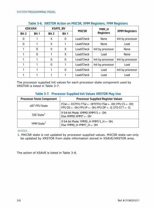
SYSTEM PROGRAMMING MODEL
The processor supplied init values for each processor state component used by XRSTOR is listed in Table 3-7.
The action of XSAVE is listed in Table 3-8.
0 1 X 0 Load/Check None Init by processor
0 1 X 1 Load/Check None Load
1 0 0 X Load/Check Init by processor None
1 0 1 X Load/Check Load None
1 1 0 0 Load/Check Init by processor Init by processor
1 1 0 1 Load/Check Init by processor Load
1 1 1 0 Load/Check Load Init by processor
1 1 1 1 Load/Check Load Load
Table 3-7. Processor Supplied Init Values XRSTOR May Use
Processor State Component Processor Supplied Register Values
x87 FPU StateFCW ← 037FH; FTW ← 0FFFFH; FSW ← 0H; FPU CS ← 0H; FPU DS ← 0H; FPU IP ← 0H; FPU DP ← 0; ST0-ST7 ← 0;
SSE State1
NOTES:
1. MXCSR state is not updated by processor supplied values. MXCSR state can onlybe updated by XRSTOR from state information stored in XSAVE/XRSTOR area.
If 64-bit Mode: XMM0-XMM15 ← 0H;Else XMM0-XMM7 ← 0H
YMM State1 If 64-bit Mode: YMM0_H-YMM15_H ← 0H;Else YMM0_H-YMM7_H ← 0H
Table 3-6. XRSTOR Action on MXCSR, XMM Registers, YMM Registers
EDX:EAX XSATE_BVMXCSR
YMM_H Registers XMM Registers
Bit 2 Bit 1 Bit 2 Bit 1
3-6 Ref. # 319433-011

SYSTEM PROGRAMMING MODEL
3.2.6 Processor Extended State Save Optimization and XSAVEOPTThe XSAVEOPT instruction paired with XRSTOR is designed to provide a high perfor-mance method for system software to perform state save and restore.A processor may indicate its support for the XSAVEOPT instruction if CPUID.(EAX=0DH, ECX=1):EAX.XSAVEOPT[Bit 0] = 1. The functionality of XSAVEOPT is similar to XSAVE. Software can use XSAVEOPT/XRSTOR in a pair-wise manner similar to XSAVE/XRSTOR to save and restore processor extended states.The syntax and operands for XSAVEOPT instructions are identical to XSAVE, i.e. the mask operand in EDX:EAX specifies the subset of enabled features to be saved. Note that software using XSAVEOPT must observe the same restrictions as XSAVE while allocating a new save area. i.e., the header area must be initialized to zeroes. The first 64-bits in the save image header starting at offset 512 are referred to as XHEADER.BV. However, the instruction differs from XSAVE in several important aspects:
1. If a component state in the processor specified by the save mask corresponds to an INIT state, the instruction may clear the corresponding bit in XHEADER.BV, but may not write out the state (unlike the XSAVE instruction, which always writes out the state).
2. If the processor determines that the component state specified by the save mask hasn't been modified since the last XRSTOR, the instruction may not write out the state to the save area.
3. A implication of this optimization is that software which needs to examine the saved image must first check the XHEADER.BV to see if any bits are clear. If the
Table 3-8. XSAVE Action on MXCSR, XMM, YMM Register
EDX:EAX XFEATURE_ENABLED_MASK MXCSR
YMM_H Registers XMM Registers
Bit 2 Bit 1 Bit 2 Bit 1
0 0 X X None None None
0 1 X 1 Store None Store
0 1 X 0 None None None
1 0 0 X None None None
1 0 1 1 Store Store None
1 1 0 0 None None None
1 1 0 1 Store None Store
1 1 1 1 Store Store Store
Ref. # 319433-011 3-7
SYSTEM PROGRAMMING MODEL
header bit is clear, it means that the state is INIT and the saved memory image may not correspond to the actual processor state.
4. The performance of XSAVEOPT will always be better than or at least equal to that of XSAVE.
3.2.6.1 XSAVEOPT Usage GuidelinesWhen using the XSAVEOPT facility, software must be aware of the following guide-lines:
1. The processor uses a tracking mechanism to determine which state components will be written to memory by the XSAVEOPT instruction. The mechanism includes three sub-conditions that are recorded internally each time XRSTOR is executed and evaluated on the invocation of the next XSAVEOPT. If a change is detected in any one of these sub-conditions, XSAVEOPT will behave exactly as XSAVE. The three sub-conditions are:
— current CPL of the logical processor
— indication whether or not the logical processor is in VMX non-root operation
— linear address of the XSAVE/XRSTOR area
2. Upon allocation of a new XSAVE/XRSTOR area and before an XSAVE or XSAVEOPT instruction is used, the save area header (HEADER.XSTATE) must be initialized to zeroes for proper operation.
3. XSAVEOPT is designed primarily for use in context switch operations. The values stored by the XSAVEOPT instruction depend on the values previously stored in a given XSAVE area.
4. Manual modifications to the XSAVE area between an XRSTOR instruction and the matching XSAVEOPT may result in data corruption.
5. For optimization to be performed properly, the XRSTOR XSAVEOPT pair must use the same segment when referencing the XSAVE area and the base of that segment must be unchanged between the two operations.
6. Software should avoid executing XSAVEOPT into a buffer from which it hadn’t previously executed a XRSTOR. For newly allocated buffers, software can execute XRSTOR with the linear address of the buffer and a restore mask of EDX:EAX = 0. Executing XRSTOR(0:0) doesn’t restore any state, but ensures expected operation of the XSAVEOPT instruction.
7. The XSAVE area can be moved or even paged, but the contents at the linear address of the save area at an XSAVEOPT must be the same as that when the previous XRSTOR was performed.
A destination operand not aligned to 64-byte boundary (in either 64-bit or 32-bit modes) will result in a general-protection (#GP) exception being generated. In 64-bit mode the upper 32 bits of RDX and RAX are ignored.
3-8 Ref. # 319433-011

SYSTEM PROGRAMMING MODEL
3.3 RESET BEHAVIORAt processor reset• YMM0-16 bits[255:0] are set to zero. • XFEATURE_ENABLED_MASK[2:1] is set to zero, XFEATURE_ENABLED_MASK[0]
is set to 1.• CR4.OSXSAVE[bit 18] (and its mirror CPUID.1.ECX.OSXSAVE[bit 27]) is set to
0.
3.4 EMULATIONSetting the CR0.EMbit to 1 provides a technique to emulate Legacy SSE floating-point instruction sets in software. This technique is not supported with AVX instruc-tions, nor FMA instructions. If an operating system wishes to emulate AVX instructions, set XFEATURE_ENABLED_MASK[2:1] to zero. This will cause AVX instructions to #UD. Emulation of FMA by operating system can be done similarly as with emulating AVX instructions.
3.5 WRITING AVX FLOATING-POINT EXCEPTION HANDLERS
AVX and FMA floating-point exceptions are handled in an entirely analogous way to Legacy SSE floating-point exceptions. To handle unmasked SIMD floating-point exceptions, the operating system or executive must provide an exception handler. The section titled “SSE and SSE2 SIMD Floating-Point Exceptions” in Chapter 11, “Programming with Streaming SIMD Extensions 2 (SSE2),” of the IA-32 Intel® Archi-tecture Software Developer’s Manual, Volume 1, describes the SIMD floating-point exception classes and gives suggestions for writing an exception handler to handle them.To indicate that the operating system provides a handler for SIMD floating-point exceptions (#XM), the CR4.OSXMMEXCPT flag (bit 10) must be set.
Ref. # 319433-011 3-9

SYSTEM PROGRAMMING MODEL
§
This page was
intentionally left
blank.
3-10 Ref. # 319433-011

INSTRUCTION FORMAT
CHAPTER 4INSTRUCTION FORMAT
AVX F16C, AVX2 and FMA instructions are encoded using a more efficient format than previous instruction extensions in the Intel 64 and IA-32 architecture. The improved encoding format uses a new prefix referred to as “VEX“. The VEX prefix may be two or three bytes long, depending on the instruction semantics. Despite the length of the VEX prefix, the instruction encoding format using VEX addresses two important issues: (a) there exists inefficiency in instruction encoding due to SIMD prefixes and some fields of the REX prefix, (b) Both SIMD prefixes and REX prefix increase in instruction byte-length. This chapter describes the instruction encoding format using VEX.VEX-prefix encoding enables a subset of AVX2 instructions to support “vector SIM“ form of memory addressing. This is described in Section 4.2.VEX-prefix encoding also enables some general purpose instructions to support three-operand syntax. This is described in Section 4.3.
4.1 INSTRUCTION FORMATSLegacy instruction set extensions in IA-32 architecture employs one or more “single-purpose“ byte as an “escape opcode“, or required SIMD prefix (66H, F2H, F3H) to expand the processing capability of the instruction set. Intel 64 architecture uses the REX prefix to expand the encoding of register access in instruction operands. Both SIMD prefixes and REX prefix carry the side effect that they can cause the length of an instruction to increase significantly. Legacy Intel 64 and IA-32 instruction set are limited to supporting instruction syntax of only two operands that can be encoded to access registers (and only one can access a memory address).Instruction encoding using VEX prefix provides several advantages:• Instruction syntax support for three operands and up-to four operands when
necessary. For example, the third source register used by VBLENDVPD is encoded using bits 7:4 of the immediate byte.
• Encoding support for vector length of 128 bits (using XMM registers) and 256 bits (using YMM registers)
• Encoding support for instruction syntax of non-destructive source operands.• Elimination of escape opcode byte (0FH), SIMD prefix byte (66H, F2H, F3H) via a
compact bit field representation within the VEX prefix.• Elimination of the need to use REX prefix to encode the extended half of general-
purpose register sets (R8-R15) for direct register access, memory addressing, or accessing XMM8-XMM15 (including YMM8-YMM15).
Ref. # 319433-011 4-1

INSTRUCTION FORMAT
• Flexible and more compact bit fields are provided in the VEX prefix to retain the full functionality provided by REX prefix. REX.W, REX.X, REX.B functionalities are provided in the three-byte VEX prefix only because only a subset of SIMD instruc-tions need them.
• Extensibility for future instruction extensions without significant instruction length increase.
Figure 4-1 shows the Intel 64 instruction encoding format with VEX prefix support. Legacy instruction without a VEX prefix is fully supported and unchanged. The use of VEX prefix in an Intel 64 instruction is optional, but a VEX prefix is required for Intel 64 instructions that operate on YMM registers or support three and four operand syntax. VEX prefix is not a constant-valued, “single-purpose” byte like 0FH, 66H, F2H, F3H in legacy SSE instructions. VEX prefix provides substantially richer capa-bility than the REX prefix.
Figure 4-1. Instruction Encoding Format with VEX Prefix
4.1.1 VEX and the LOCK prefixAny VEX-encoded instruction with a LOCK prefix preceding VEX will #UD.
4.1.2 VEX and the 66H, F2H, and F3H prefixesAny VEX-encoded instruction with a 66H, F2H, or F3H prefix preceding VEX will #UD.
4.1.3 VEX and the REX prefixAny VEX-encoded instruction with a REX prefix proceeding VEX will #UD.
4.1.4 The VEX Prefix The VEX prefix is encoded in either the two-byte form (the first byte must be C5H) or in the three-byte form (the first byte must be C4H). The two-byte VEX is used mainly for 128-bit, scalar and the most common 256-bit AVX instructions, while the three-byte VEX provides a compact replacement of REX and 3-byte opcode instructions (including AVX and FMA instructions). Beyond the first byte of the VEX prefix it
ModR/M
1
[Prefixes] [VEX] OPCODE [SIB] [DISP] [IMM]
2,3 1 0,1 0,1,2,4 0,1# Bytes
4-2 Ref. # 319433-011
INSTRUCTION FORMAT
consists of a number of bit fields providing specific capability; they are shown in Figure 4-2. The bit fields of the VEX prefix can be summarized by its functional purposes:• Non-destructive source register encoding (applicable to three and four operand
syntax): This is the first source operand in the instruction syntax. It is represented by the notation, VEX.vvvv. This field is encoded using 1’s complement form (inverted form), i.e. XMM0/YMM0/R0 is encoded as 1111B, XMM15/YMM15/R15 is encoded as 0000B.
• Vector length encoding: This 1-bit field represented by the notation VEX.L. L= 0 means vector length is 128 bits wide, L=1 means 256 bit vector. The value of this field is written as VEX.128 or VEX.256 in this document to distinguish encoded values of other VEX bit fields.
• REX prefix functionality: Full REX prefix functionality is provided in the three-byte form of VEX prefix. However the VEX bit fields providing REX functionality are encoded using 1’s complement form, i.e. XMM0/YMM0/R0 is encoded as 1111B, XMM15/YMM15/R15 is encoded as 0000B.
— Two-byte form of the VEX prefix only provides the equivalent functionality of REX.R, using 1’s complement encoding. This is represented as VEX.R.
— Three-byte form of the VEX prefix provides REX.R, REX.X, REX.B functionality using 1’s complement encoding and three dedicated bit fields represented as VEX.R, VEX.X, VEX.B.
— Three-byte form of the VEX prefix provides the functionality of REX.W only to specific instructions that need to override default 32-bit operand size for a general purpose register to 64-bit size in 64-bit mode. For those applicable instructions, VEX.W field provides the same functionality as REX.W. VEX.W field can provide completely different functionality for other instructions.
Consequently, the use of REX prefix with VEX encoded instructions is notallowed. However, the intent of the REX prefix for expanding register set isreserved for future instruction set extensions using VEX prefix encoding format.
• Compaction of SIMD prefix: Legacy SSE instructions effectively use SIMD prefixes (66H, F2H, F3H) as an opcode extension field. VEX prefix encoding allows the functional capability of such legacy SSE instructions (operating on XMM registers, bits 255:128 of corresponding YMM unmodified) to be encoded using the VEX.pp field without the presence of any SIMD prefix. The VEX-encoded 128-bit instruction will zero-out bits 255:128 of the destination register. VEX-encoded instruction may have 128 bit vector length or 256 bits length.
• Compaction of two-byte and three-byte opcode: More recently introduced legacy SSE instructions employ two and three-byte opcode. The one or two leading bytes are: 0FH, and 0FH 3AH/0FH 38H. The one-byte escape (0FH) and two-byte escape (0FH 3AH, 0FH 38H) can also be interpreted as an opcode extension field. The VEX.mmmmm field provides compaction to allow many legacy instruction to be encoded without the constant byte sequence, 0FH, 0FH 3AH, 0FH 38H. These VEX-encoded instruction may have 128 bit vector length or 256 bits length.
Ref. # 319433-011 4-3

INSTRUCTION FORMAT
The VEX prefix is required to be the last prefix and immediately precedes the opcode bytes. It must follow any other prefixes. If VEX prefix is present a REX prefix is not supported. The 3-byte VEX leaves room for future expansion with 3 reserved bits. REX and the 66h/F2h/F3h prefixes are reclaimed for future use.VEX prefix has a two-byte form and a three byte form. If an instruction syntax can be encoded using the two-byte form, it can also be encoded using the three byte form of VEX. The latter increases the length of the instruction by one byte. This may be helpful in some situations for code alignment. The VEX prefix supports 256-bit versions of floating-point SSE, SSE2, SSE3, and SSE4 instructions. VEX-encoded 128-bit vector integer instructions are supported in AVX. 256-bit vector integer instructions are supported in AVX2 but not AVX. Table A-1 of Appendix A lists promoted, VEX-128 encoded vector integer instructions in AVX. Table A-2 lists 128-bit and 256-bit, promoted VEX-encoded vector integer instructions. Note, certain new instruction functionality can only be encoded with the VEX prefix (See Appendix A, Table A-3, Table A-4, Table A-5).The VEX prefix will #UD on any instruction containing MMX register sources or desti-nations.The following subsections describe the various fields in two or three-byte VEX prefix:
4.1.4.1 VEX Byte 0, bits[7:0] VEX Byte 0, bits [7:0] must contain the value 11000101b (C5h) or 11000100b (C4h). The 3-byte VEX uses the C4h first byte, while the 2-byte VEX uses the C5h first byte.
4.1.4.2 VEX Byte 1, bit [7] - ‘R’VEX Byte 1, bit [7] contains a bit analogous to a bit inverted REX.R. In protected and compatibility modes the bit must be set to ‘1’ otherwise the instruction is LES or LDS. This bit is present in both 2- and 3-byte VEX prefixes. The usage of WRXB bits for legacy instructions is explained in detail section 2.2.1.2 of Intel 64 and IA-32 Archi-tectures Software developer’s manual, Volume 2A. This bit is stored in bit inverted format.
4.1.4.3 3-byte VEX byte 1, bit[6] - ‘X’ Bit[6] of the 3-byte VEX byte 1 encodes a bit analogous to a bit inverted REX.X. It is an extension of the SIB Index field in 64-bit modes. In 32-bit modes, this bit must be set to ‘1’ otherwise the instruction is LES or LDS. This bit is available only in the 3-byte VEX prefix. This bit is stored in bit inverted format.
4-4 Ref. # 319433-011

INSTRUCTION FORMAT
Figure 4-2. VEX bitfields
11000100 1
670
vvvv
1 03 2
L
7
R: REX.R in 1’s complement (inverted) form
00000: Reserved for future use (will #UD)00001: implied 0F leading opcode byte00010: implied 0F 38 leading opcode bytes00011: implied 0F 3A leading opcode bytes00100-11111: Reserved for future use (will #UD)
Byte 0 Byte 2
(Bit Position)
vvvv: a register specifier (in 1’s complement form) or 1111 if unused.
67 0
R X B
Byte 1
pp: opcode extension providing equivalent functionality of a SIMD prefix
W: opcode specific (use like REX.W, or used for opcode
m-mmmm
5
m-mmmm:
W
L: Vector Length
0: Same as REX.R=1 (64-bit mode only)1: Same as REX.R=0 (must be 1 in 32-bit mode)
4
pp 3-byte VEX
11000101 1
670
vvvv
1 03 2
L
7
R pp 2-byte VEX
B: REX.B in 1’s complement (inverted) form
0: Same as REX.B=1 (64-bit mode only)1: Same as REX.B=0 (Ignored in 32-bit mode).
extension, or ignored, depending on the opcode byte)
0: scalar or 128-bit vector1: 256-bit vector
00: None01: 6610: F311: F2
0: Same as REX.X=1 (64-bit mode only)1: Same as REX.X=0 (must be 1 in 32-bit mode)
X: REX.X in 1’s complement (inverted) form
Ref. # 319433-011 4-5

INSTRUCTION FORMAT
4.1.4.4 3-byte VEX byte 1, bit[5] - ‘B’ Bit[5] of the 3-byte VEX byte 1 encodes a bit analogous to a bit inverted REX.B. In 64-bit modes, it is an extension of the ModR/M r/m field, or the SIB base field. In 32-bit modes, this bit is ignored.This bit is available only in the 3-byte VEX prefix.This bit is stored in bit inverted format.
4.1.4.5 3-byte VEX byte 2, bit[7] - ‘W’ Bit[7] of the 3-byte VEX byte 2 is represented by the notation VEX.W. It can provide following functions, depending on the specific opcode. • For AVX instructions that have equivalent legacy SSE instructions (typically
these SSE instructions have a general-purpose register operand with its oper-and size attribute promotable by REX.W), if REX.W promotes the operand size attribute of the general-purpose register operand in legacy SSE instruction, VEX.W has same meaning in the corresponding AVX equivalent form. In 32-bit modes, VEX.W is silently ignored.
• For AVX instructions that have equivalent legacy SSE instructions (typically these SSE instructions have operands with their operand size attribute fixed and not promotable by REX.W), if REX.W is don’t care in legacy SSE instruction, VEX.W is ignored in the corresponding AVX equivalent form irrespective of mode.
• For new AVX instructions where VEX.W has no defined function (typically these meant the combination of the opcode byte and VEX.mmmmm did not have any equivalent SSE functions), VEX.W is reserved as zero and setting to other than zero will cause instruction to #UD.
4.1.4.6 2-byte VEX Byte 1, bits[6:3] and 3-byte VEX Byte 2, bits [6:3]- ‘vvvv’ the Source or dest Register Specifier
In 32-bit mode the VEX first byte C4 and C5 alias onto the LES and LDS instructions. To maintain compatibility with existing programs the VEX 2nd byte, bits [7:6] must be 11b. To achieve this, the VEX payload bits are selected to place only inverted, 64-bit valid fields (extended register selectors) in these upper bits. The 2-byte VEX Byte 1, bits [6:3] and the 3-byte VEX, Byte 2, bits [6:3] encode a field (shorthand VEX.vvvv) that for instructions with 2 or more source registers and an XMM or YMM or memory destination encodes the first source register specifier stored in inverted (1’s complement) form. VEX.vvvv is not used by the instructions with one source (except certain shifts, see below) or on instructions with no XMM or YMM or memory destination. If an instruc-tion does not use VEX.vvvv then it should be set to 1111b otherwise instruction will #UD.In 64-bit mode all 4 bits may be used. See Table 4-1 for the encoding of the XMM or YMM registers. In 32-bit and 16-bit modes bit 6 must be 1 (if bit 6 is not 1, the 2-byte
4-6 Ref. # 319433-011

INSTRUCTION FORMAT
VEX version will generate LDS instruction and the 3-byte VEX version will ignore this bit).
Table 4-1. VEX.vvvv to register name mapping
The VEX.vvvv field is encoded in bit inverted format for accessing a register oper-and.
4.1.5 Instruction Operand Encoding and VEX.vvvv, ModR/MVEX-encoded instructions support three-operand and four-operand instruction syntax. Some VEX-encoded instructions have syntax with less than three operands, e.g. VEX-encoded pack shift instructions support one source operand and one desti-nation operand). The roles of VEX.vvvv, reg field of ModR/M byte (ModR/M.reg), r/m field of ModR/M byte (ModR/M.r/m) with respect to encoding destination and source operands vary with different type of instruction syntax.The role of VEX.vvvv can be summarized to three situations:• VEX.vvvv encodes the first source register operand, specified in inverted (1’s
complement) form and is valid for instructions with 2 or more source operands.
VEX.vvvv Dest RegisterValid in Legacy/Compatibility
32-bit modes?
1111B XMM0/YMM0 Valid
1110B XMM1/YMM1 Valid
1101B XMM2/YMM2 Valid
1100B XMM3/YMM3 Valid
1011B XMM4/YMM4 Valid
1010B XMM5/YMM5 Valid
1001B XMM6/YMM6 Valid
1000B XMM7/YMM7 Valid
0111B XMM8/YMM8 Invalid
0110B XMM9/YMM9 Invalid
0101B XMM10/YMM10 Invalid
0100B XMM11/YMM11 Invalid
0011B XMM12/YMM12 Invalid
0010B XMM13/YMM13 Invalid
0001B XMM14/YMM14 Invalid
0000B XMM15/YMM15 Invalid
Ref. # 319433-011 4-7
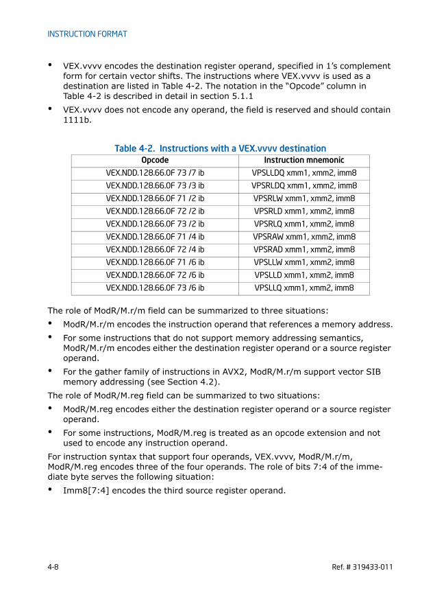
INSTRUCTION FORMAT
• VEX.vvvv encodes the destination register operand, specified in 1’s complement form for certain vector shifts. The instructions where VEX.vvvv is used as a destination are listed in Table 4-2. The notation in the “Opcode” column in Table 4-2 is described in detail in section 5.1.1
• VEX.vvvv does not encode any operand, the field is reserved and should contain 1111b.
Table 4-2. Instructions with a VEX.vvvv destination
The role of ModR/M.r/m field can be summarized to three situations:• ModR/M.r/m encodes the instruction operand that references a memory address.• For some instructions that do not support memory addressing semantics,
ModR/M.r/m encodes either the destination register operand or a source register operand.
• For the gather family of instructions in AVX2, ModR/M.r/m support vector SIB memory addressing (see Section 4.2).
The role of ModR/M.reg field can be summarized to two situations:• ModR/M.reg encodes either the destination register operand or a source register
operand.• For some instructions, ModR/M.reg is treated as an opcode extension and not
used to encode any instruction operand.For instruction syntax that support four operands, VEX.vvvv, ModR/M.r/m, ModR/M.reg encodes three of the four operands. The role of bits 7:4 of the imme-diate byte serves the following situation:• Imm8[7:4] encodes the third source register operand.
Opcode Instruction mnemonic
VEX.NDD.128.66.0F 73 /7 ib VPSLLDQ xmm1, xmm2, imm8
VEX.NDD.128.66.0F 73 /3 ib VPSRLDQ xmm1, xmm2, imm8
VEX.NDD.128.66.0F 71 /2 ib VPSRLW xmm1, xmm2, imm8
VEX.NDD.128.66.0F 72 /2 ib VPSRLD xmm1, xmm2, imm8
VEX.NDD.128.66.0F 73 /2 ib VPSRLQ xmm1, xmm2, imm8
VEX.NDD.128.66.0F 71 /4 ib VPSRAW xmm1, xmm2, imm8
VEX.NDD.128.66.0F 72 /4 ib VPSRAD xmm1, xmm2, imm8
VEX.NDD.128.66.0F 71 /6 ib VPSLLW xmm1, xmm2, imm8
VEX.NDD.128.66.0F 72 /6 ib VPSLLD xmm1, xmm2, imm8
VEX.NDD.128.66.0F 73 /6 ib VPSLLQ xmm1, xmm2, imm8
4-8 Ref. # 319433-011
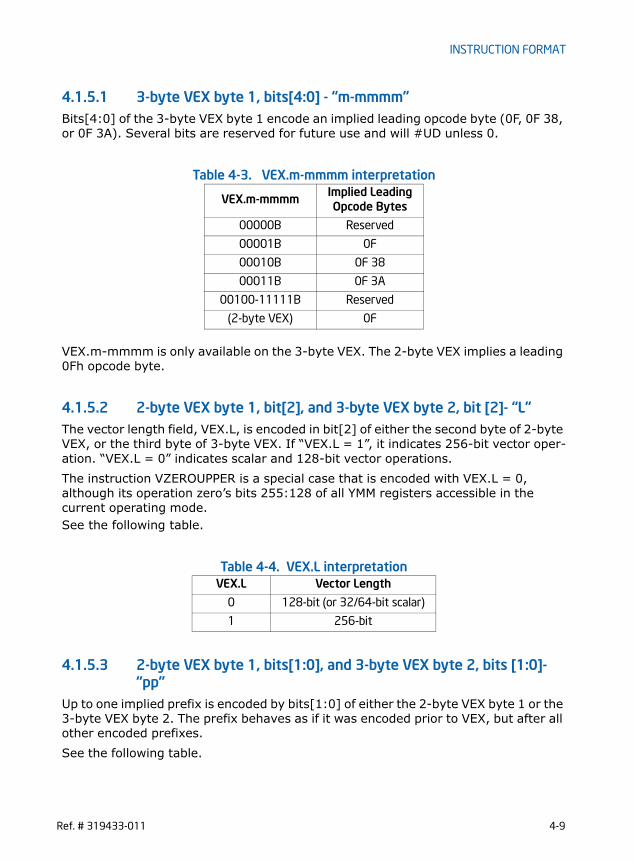
INSTRUCTION FORMAT
4.1.5.1 3-byte VEX byte 1, bits[4:0] - “m-mmmm” Bits[4:0] of the 3-byte VEX byte 1 encode an implied leading opcode byte (0F, 0F 38, or 0F 3A). Several bits are reserved for future use and will #UD unless 0.
Table 4-3. VEX.m-mmmm interpretation
VEX.m-mmmm is only available on the 3-byte VEX. The 2-byte VEX implies a leading 0Fh opcode byte.
4.1.5.2 2-byte VEX byte 1, bit[2], and 3-byte VEX byte 2, bit [2]- “L”The vector length field, VEX.L, is encoded in bit[2] of either the second byte of 2-byte VEX, or the third byte of 3-byte VEX. If “VEX.L = 1”, it indicates 256-bit vector oper-ation. “VEX.L = 0” indicates scalar and 128-bit vector operations.The instruction VZEROUPPER is a special case that is encoded with VEX.L = 0, although its operation zero’s bits 255:128 of all YMM registers accessible in the current operating mode.See the following table.
Table 4-4. VEX.L interpretation
4.1.5.3 2-byte VEX byte 1, bits[1:0], and 3-byte VEX byte 2, bits [1:0]- “pp”
Up to one implied prefix is encoded by bits[1:0] of either the 2-byte VEX byte 1 or the 3-byte VEX byte 2. The prefix behaves as if it was encoded prior to VEX, but after all other encoded prefixes.See the following table.
VEX.m-mmmm Implied Leading Opcode Bytes
00000B Reserved
00001B 0F
00010B 0F 38
00011B 0F 3A
00100-11111B Reserved
(2-byte VEX) 0F
VEX.L Vector Length
0 128-bit (or 32/64-bit scalar)
1 256-bit
Ref. # 319433-011 4-9

INSTRUCTION FORMAT
Table 4-5. VEX.pp interpretation
4.1.6 The Opcode ByteOne (and only one) opcode byte follows the 2 or 3 byte VEX. Legal opcodes are spec-ified in Appendix B, in color. Any instruction that uses illegal opcode will #UD.
4.1.7 The MODRM, SIB, and Displacement BytesThe encodings are unchanged but the interpretation of reg_field or rm_field differs (see above).
4.1.8 The Third Source Operand (Immediate Byte)VEX-encoded instructions can support instruction with a four operand syntax. VBLENDVPD, VBLENDVPS, and PBLENDVB use imm8[7:4] to encode one of the source registers.
4.1.9 AVX Instructions and the Upper 128-bits of YMM registersIf an instruction with a destination XMM register is encoded with a VEX prefix, the processor zeroes the upper 128 bits of the equivalent YMM register. Legacy SSE instructions without VEX preserve the upper 128-bits.
4.1.9.1 Vector Length Transition and Programming Considerations An instruction encoded with a VEX.128 prefix that loads a YMM register operand operates as follows:• Data is loaded into bits 127:0 of the register• Bits above bit 127 in the register are cleared.Thus, such an instruction clears bits 255:128 of a destination YMM register on processors with a maximum vector-register width of 256 bits. In the event that future processors extend the vector registers to greater widths, an instruction encoded with a VEX.128 or VEX.256 prefix will also clear any bits beyond bit 255.
ppImplies this prefix after other
prefixes but before VEX
00B None
01B 66
10B F3
11B F2
4-10 Ref. # 319433-011
INSTRUCTION FORMAT
(This is in contrast with legacy SSE instructions, which have no VEX prefix; these modify only bits 127:0 of any destination register operand.)Programmers should bear in mind that instructions encoded with VEX.128 and VEX.256 prefixes will clear any future extensions to the vector registers. A calling function that uses such extensions should save their state before calling legacy func-tions. This is not possible for involuntary calls (e.g., into an interrupt-service routine). It is recommended that software handling involuntary calls accommodate this by not executing instructions encoded with VEX.128 and VEX.256 prefixes. In the event that it is not possible or desirable to restrict these instructions, then soft-ware must take special care to avoid actions that would, on future processors, zero the upper bits of vector registers. Processors that support further vector-register extensions (defining bits beyond bit 255) will also extend the XSAVE and XRSTOR instructions to save and restore these extensions. To ensure forward compatibility, software that handles involuntary calls and that uses instructions encoded with VEX.128 and VEX.256 prefixes should first save and then restore the vector registers (with any extensions) using the XSAVE and XRSTOR instructions with save/restore masks that set bits that correspond to all vector-register extensions. Ideally, software should rely on a mechanism that is cognizant of which bits to set. (E.g., an OS mechanism that sets the save/restore mask bits for all vector-register extensions that are enabled in XCR0.) Saving and restoring state with instructions other than XSAVE and XRSTOR will, on future processors with wider vector registers, corrupt the extended state of the vector registers - even if doing so functions correctly on processors supporting 256-bit vector registers. (The same is true if XSAVE and XRSTOR are used with a save/restore mask that does not set bits corresponding to all supported extensions to the vector registers.)
4.1.10 AVX Instruction LengthThe AVX and FMA instructions described in this document (including VEX and ignoring other prefixes) do not exceed 11 bytes in length, but may increase in the future. The maximum length of an Intel 64 and IA-32 instruction remains 15 bytes.
4.2 VECTOR SIB (VSIB) MEMORY ADDRESSING In AVX2, an SIB byte that follows the ModR/M byte can support VSIB memory addressing to an array of linear addresses. VSIB addressing is only supported in a subset of AVX2 instructions. VSIB memory addressing requires 32-bit or 64-bit effec-tive address. In 32-bit mode, VSIB addressing is not supported when address size attribute is overridden to 16 bits. In 16-bit protected mode, VSIB memory addressing is permitted if address size attribute is overridden to 32 bits. Additionally, VSIB memory addressing is supported only with VEX prefix.In VSIB memory addressing, the SIB byte consists of:• The scale field (bit 7:6) specifies the scale factor.
Ref. # 319433-011 4-11

INSTRUCTION FORMAT
• The index field (bits 5:3) specifies the register number of the vector index register, each element in the vector register specifies an index.
• The base field (bits 2:0) specifies the register number of the base register.
Table 4-6 shows the 32-bit VSIB addressing form. It is organized to give 256 possible values of the SIB byte (in hexadecimal). General purpose registers used as a base are indicated across the top of the table, along with corresponding values for the SIB byte’s base field. The register names also include R8L-R15L applicable only in 64-bit mode (when address size override prefix is used, but the value of VEX.B is not shown in Table 4-6). In 32-bit mode, R8L-R15L does not apply.Table rows in the body of the table indicate the vector index register used as the index field and each supported scaling factor shown separately. Vector registers used in the index field can be XMM or YMM registers. The left-most column includes vector registers VR8-VR15, which are only available in 64-bit mode and does not apply if encoding in 32-bit mode.
Table 4-6. 32-Bit VSIB Addressing Forms of the SIB Byter32
(In decimal) Base =(In binary) Base =
EAX/R8L0000
ECX/R9L1001
EDX/R10L2010
EBX/R11L3011
ESP/R12L4100
EBP/R13L1
5101
ESI/R14L6110
EDI/R15L7111
Scaled Index SS Index Value of SIB Byte (in Hexadecimal)
VR0/VR8VR1/VR9VR2/VR10VR3/VR11VR4/VR12VR5/VR13VR6/VR14VR7/VR15
*1 00 000001010011100101110111
0008101820283038
0109111921293139
020A121A222A323A
030B131B232B333B
040C141C242C343C
050D151D252D353D
060E161E262E363E
070F171F272F373F
VR0/VR8VR1/VR9VR2/VR10VR3/VR11VR4/VR12VR5/VR13VR6/VR14VR7/VR15
*2 01 000001010011100101110111
4048505860687078
4149515961697179
424A525A626A727A
434B535B636B737B
444C545C646C747C
454D555D656D757D
464E565E666E767E
474F575F676F777F
VR0/VR8VR1/VR9VR2/VR10VR3/VR11VR4/VR12VR5/VR13VR6/VR14VR7/VR15
*4 10 000001010011100101110111
80889098A0A8B0B8
81899189A1A9B1B9
828A929AA2AAB2BA
838B939BA3ABB3BB
848C949CA4ACB4BC
858D959DA5ADB5BD
868E969EA6AEB6BE
878F979FA7AFB7BF
4-12 Ref. # 319433-011

INSTRUCTION FORMAT
4.2.1 64-bit Mode VSIB Memory Addressing In 64-bit mode VSIB memory addressing uses the VEX.B field and the base field of the SIB byte to encode one of the 16 general-purpose register as the base register. The VEX.X field and the index field of the SIB byte encode one of the 16 vector regis-ters as the vector index register. In 64-bit mode the top row of Table 4-6 base register should be interpreted as the full 64-bit of each register.
4.3 VEX ENCODING SUPPORT FOR GPR INSTRUCTIONS VEX prefix may be used to encode instructions that operate on neither YMM nor XMM registers. VEX-encoded general-purpose-register instructions have the following properties:• Instruction syntax support for three encodable operands.• Encoding support for instruction syntax of non-destructive source operand,
destination operand encoded via VEX.vvvv, and destructive three-operand syntax.
• Elimination of escape opcode byte (0FH), two-byte escape via a compact bit field representation within the VEX prefix.
• Elimination of the need to use REX prefix to encode the extended half of general-purpose register sets (R8-R15) for direct register access or memory addressing.
• Flexible and more compact bit fields are provided in the VEX prefix to retain the full functionality provided by REX prefix. REX.W, REX.X, REX.B functionalities are provided in the three-byte VEX prefix only.
VR0/VR8VR1/VR9VR2/VR10VR3/VR11VR4/VR12VR5/VR13VR6/VR14VR7/VR15
*8 11 000001010011100101110111
C0C8D0D8E0E8F0F8
C1C9D1D9E1E9F1F9
C2CAD2DAE2EAF2FA
C3CBD3DBE3EBF3FB
C4CCD4DCE4ECF4FC
C5CDD5DDE5EDF5FD
C6CED6DEE6EEF6FE
C7CFD7DFE7EFF7FF
NOTES:
1. If ModR/M.mod = 00b, then effective address is computed as [scaled vector index] + disp32. Other-wise the effective address is computed as [EBP/R13]+ disp, the displacement is either 8 bit or 32 bitdepending on the value of ModR/M.mod:
MOD Effective Address00b [Scaled Vector Register] + Disp3201b [Scaled Vector Register] + Disp8 + [EBP/R13]10b [Scaled Vector Register] + Disp32 + [EBP/R13]
Table 4-6. 32-Bit VSIB Addressing Forms of the SIB Byte
Ref. # 319433-011 4-13
INSTRUCTION FORMAT
• VEX-encoded GPR instructions are encoded with VEX.L=0.Any VEX-encoded GPR instruction with a 66H, F2H, or F3H prefix preceding VEX will #UD.Any VEX-encoded GPR instruction with a REX prefix proceeding VEX will #UD. VEX-encoded GPR instructions are not supported in real and virtual 8086 modes.
§
4-14 Ref. # 319433-011

INSTRUCTION SET REFERENCE
CHAPTER 5INSTRUCTION SET REFERENCE
Instructions that are described in this document follow the general documentation convention established in Intel 64 and IA-32 Architectures Software Developer’s Manual Volume 2A and 2B. Additional notations and conventions adopted in this document are listed in Section 5.1. Section 5.2 covers supplemental information that applies to a specific subset of instructions.
5.1 INTERPRETING INSTRUCTION REFERENCE PAGESThis section describes the format of information contained in the instruction refer-ence pages in this chapter. It explains notational conventions and abbreviations used in these sections that are outside of those conventions described in Section 3.1 of the Intel 64 and IA-32 Architectures Software Developer’s Manual Volume 2A.
5.1.1 Instruction FormatThe following is an example of the format used for each instruction description in this chapter. The table below provides an example summary table:
Ref. # 319433-011 5-1

INSTRUCTION SET REFERENCE
(V)ADDSD- ADD Scalar Double-Precision Floating-Point Values (THIS IS AN EXAMPLE)
Instruction Operand Encoding
5.1.2 Opcode Column in the Instruction Summary TableFor notation and conventions applicable to instructions that do not use VEX prefix, consult Section 3.1 of the Intel 64 and IA-32 Architectures Software Developer’s Manual Volume 2A.In the Instruction Summary Table, the Opcode column presents each instruction encoded using the VEX prefix in following form (including the modR/M byte if appli-cable, the immediate byte if applicable):VEX.[NDS,NDD,DDS].[128,256,LZ,LIG].[66,F2,F3].0F/0F3A/0F38.[W0,W1, WIG] opcode [/r] [/ib,/is4]• VEX: indicates the presence of the VEX prefix is required. The VEX prefix can be
encoded using the three-byte form (the first byte is C4H), or using the two-byte form (the first byte is C5H). The two-byte form of VEX only applies to those instructions that do not require the following fields to be encoded:
Opcode/Instruction
Op/En
64/32-bit Mode
CPUID Feature Flag
Description
F2 0F 58 /r A V/V SSE2 Add the low double-preci-sion floating-point value from xmm2/mem to xmm1 and store the result in xmm1
ADDSD xmm1, xmm2/m64VEX.NDS.128.F2.0F.WIG 58 /r B V/V AVX Add the low double-preci-
sion floating-point value from xmm3/mem to xmm2 and store the result in xmm1
VADDSD xmm1, xmm2, xmm3/m64
Op/En Operand 1 Operand 2 Operand 3 Operand 4
A ModRM:reg (w) ModRM:r/m (r) NA NA
B ModRM:reg (w) VEX.vvvv (r) ModRM:r/m (r) NA
5-2 Ref. # 319433-011

INSTRUCTION SET REFERENCE
VEX.mmmmm, VEX.W, VEX.X, VEX.B. Refer to Section 4.1.4 for more detail on the VEX prefixThe encoding of various sub-fields of the VEX prefix is described using thefollowing notations:
— NDS, NDD, DDS: specifies that VEX.vvvv field is valid for the encoding of a register operand:
• VEX.NDS: VEX.vvvv encodes the first source register in an instruction syntax where the content of source registers will be preserved.
• VEX.NDD: VEX.vvvv encodes the destination register that cannot be encoded by ModR/M:reg field.
• VEX.DDS: VEX.vvvv encodes the second source register in a three-operand instruction syntax where the content of first source register will be overwritten by the result.
• If none of NDS, NDD, and DDS is present, VEX.vvvv must be 1111b (i.e. VEX.vvvv does not encode an operand). The VEX.vvvv field can be encoded using either the 2-byte or 3-byte form of the VEX prefix.
— 128,256,LZ,LIG: VEX.L field can be 0 (denoted by VEX.128 or VEX.LZ) or 1 (denoted by VEX.256). The VEX.L field can be encoded using either the 2-byte or 3-byte form of the VEX prefix. The presence of the notation VEX.256 or VEX.128 in the opcode column should be interpreted as follows:
• If VEX.256 is present in the opcode column: The semantics of the instruction must be encoded with VEX.L = 1. An attempt to encode this instruction with VEX.L= 0 can result in one of two situations: (a) if VEX.128 version is defined, the processor will behave according to the defined VEX.128 behavior; (b) an #UD occurs if there is no VEX.128 version defined.
• If VEX.128 is present in the opcode column but there is no VEX.256 version defined for the same opcode byte: Two situations apply: (a) For VEX-encoded, 128-bit SIMD integer instructions, software must encode the instruction with VEX.L = 0. The processor will treat the opcode byte encoded with VEX.L= 1 by causing an #UD exception; (b) For VEX-encoded, 128-bit packed floating-point instructions, software must encode the instruction with VEX.L = 0. The processor will treat the opcode byte encoded with VEX.L= 1 by causing an #UD exception (e.g. VMOVLPS).
• If VEX.LIG is present in the opcode column: The VEX.L value is ignored. This generally applies to VEX-encoded scalar SIMD floating-point instruc-tions. Scalar SIMD floating-point instruction can be distinguished from the mnemonic of the instruction. Generally, the last two letters of the instruction mnemonic would be either “SS“, “SD“, or “SI“ for SIMD floating-point conversion instructions.
Ref. # 319433-011 5-3

INSTRUCTION SET REFERENCE
• If VEX.LZ is present in the opcode column: The VEX.L must be encoded to be 0B, an #UD occurs if VEX.L is not zero.
— 66,F2,F3: The presence or absence of these value maps to the VEX.pp field encodings. If absent, this corresponds to VEX.pp=00B. If present, the corre-sponding VEX.pp value affects the “opcode” byte in the same way as if a SIMD prefix (66H, F2H or F3H) does to the ensuing opcode byte. Thus a non-zero encoding of VEX.pp may be considered as an implied 66H/F2H/F3H prefix. The VEX.pp field may be encoded using either the 2-byte or 3-byte form of the VEX prefix.
— 0F,0F3A,0F38: The presence maps to a valid encoding of the VEX.mmmmm field. Only three encoded values of VEX.mmmmm are defined as valid, corre-sponding to the escape byte sequence of 0FH, 0F3AH and 0F38H. The effect of a valid VEX.mmmmm encoding on the ensuing opcode byte is same as if the corresponding escape byte sequence on the ensuing opcode byte for non-VEX encoded instructions. Thus a valid encoding of VEX.mmmmm may be consider as an implies escape byte sequence of either 0FH, 0F3AH or 0F38H. The VEX.mmmmm field must be encoded using the 3-byte form of VEX prefix.
— 0F,0F3A,0F38 and 2-byte/3-byte VEX. The presence of 0F3A and 0F38 in the opcode column implies that opcode can only be encoded by the three-byte form of VEX. The presence of 0F in the opcode column does not preclude the opcode to be encoded by the two-byte of VEX if the semantics of the opcode does not require any subfield of VEX not present in the two-byte form of the VEX prefix.
— W0: VEX.W=0.
— W1: VEX.W=1.
— The presence of W0/W1 in the opcode column applies to two situations: (a) it is treated as an extended opcode bit, (b) the instruction semantics support an operand size promotion to 64-bit of a general-purpose register operand or a 32-bit memory operand. The presence of W1 in the opcode column implies the opcode must be encoded using the 3-byte form of the VEX prefix. The presence of W0 in the opcode column does not preclude the opcode to be encoded using the C5H form of the VEX prefix, if the semantics of the opcode does not require other VEX subfields not present in the two-byte form of the VEX prefix. Please see Section 4.1.4 on the subfield definitions within VEX.
— WIG: If WIG is present, the instruction may be encoded using the C5H form (if VEX.mmmmm is not required); or when using the C4H form of VEX prefix, VEX.W value is ignored.
• opcode: Instruction opcode.• /r — Indicates that the ModR/M byte of the instruction contains a register
operand and an r/m operand.• ib: A 1-byte immediate operand to the instruction that follows the opcode,
ModR/M bytes or scale/indexing bytes.
5-4 Ref. # 319433-011
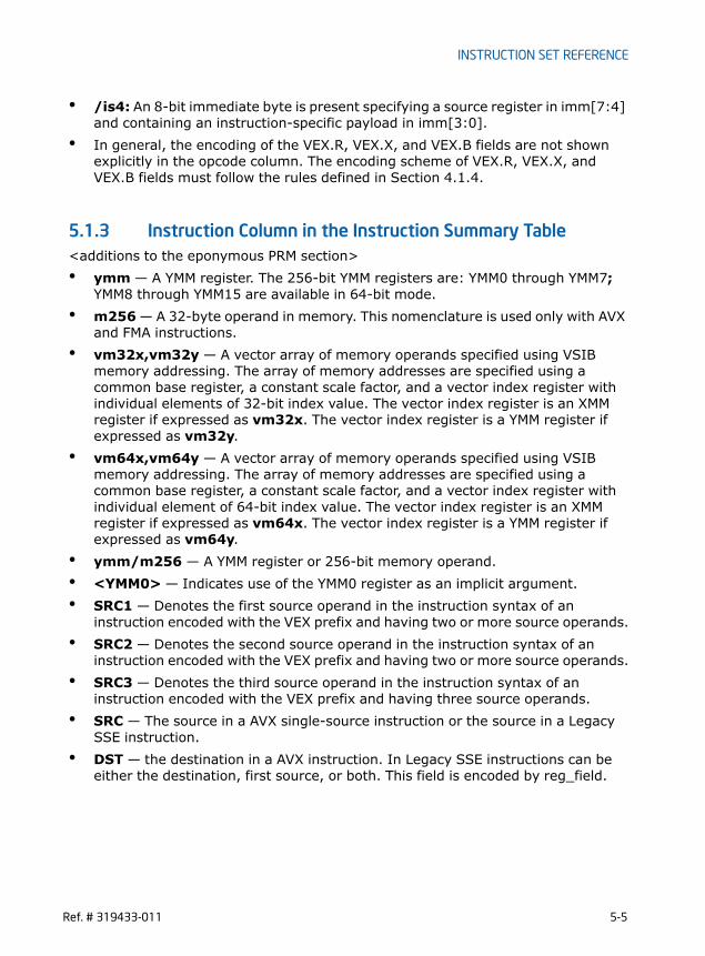
INSTRUCTION SET REFERENCE
• /is4: An 8-bit immediate byte is present specifying a source register in imm[7:4] and containing an instruction-specific payload in imm[3:0].
• In general, the encoding of the VEX.R, VEX.X, and VEX.B fields are not shown explicitly in the opcode column. The encoding scheme of VEX.R, VEX.X, and VEX.B fields must follow the rules defined in Section 4.1.4.
5.1.3 Instruction Column in the Instruction Summary Table<additions to the eponymous PRM section>• ymm — A YMM register. The 256-bit YMM registers are: YMM0 through YMM7;
YMM8 through YMM15 are available in 64-bit mode.• m256 — A 32-byte operand in memory. This nomenclature is used only with AVX
and FMA instructions.• vm32x,vm32y — A vector array of memory operands specified using VSIB
memory addressing. The array of memory addresses are specified using a common base register, a constant scale factor, and a vector index register with individual elements of 32-bit index value. The vector index register is an XMM register if expressed as vm32x. The vector index register is a YMM register if expressed as vm32y.
• vm64x,vm64y — A vector array of memory operands specified using VSIB memory addressing. The array of memory addresses are specified using a common base register, a constant scale factor, and a vector index register with individual element of 64-bit index value. The vector index register is an XMM register if expressed as vm64x. The vector index register is a YMM register if expressed as vm64y.
• ymm/m256 — A YMM register or 256-bit memory operand. • <YMM0> — Indicates use of the YMM0 register as an implicit argument.• SRC1 — Denotes the first source operand in the instruction syntax of an
instruction encoded with the VEX prefix and having two or more source operands.• SRC2 — Denotes the second source operand in the instruction syntax of an
instruction encoded with the VEX prefix and having two or more source operands.• SRC3 — Denotes the third source operand in the instruction syntax of an
instruction encoded with the VEX prefix and having three source operands.• SRC — The source in a AVX single-source instruction or the source in a Legacy
SSE instruction.• DST — the destination in a AVX instruction. In Legacy SSE instructions can be
either the destination, first source, or both. This field is encoded by reg_field.
Ref. # 319433-011 5-5
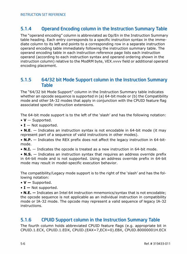
INSTRUCTION SET REFERENCE
5.1.4 Operand Encoding column in the Instruction Summary TableThe “operand encoding” column is abbreviated as Op/En in the Instruction Summary table heading. Each entry corresponds to a specific instruction syntax in the imme-diate column to its left and points to a corresponding row in a separate instruction operand encoding table immediately following the instruction summary table. The operand encoding table in each instruction reference page lists each instruction operand (according to each instruction syntax and operand ordering shown in the instruction column) relative to the ModRM byte, VEX.vvvv field or additional operand encoding placement.
5.1.5 64/32 bit Mode Support column in the Instruction Summary Table
The “64/32 bit Mode Support” column in the Instruction Summary table indicates whether an opcode sequence is supported in (a) 64-bit mode or (b) the Compatibility mode and other IA-32 modes that apply in conjunction with the CPUID feature flag associated specific instruction extensions.
The 64-bit mode support is to the left of the ‘slash’ and has the following notation:• V — Supported.• I — Not supported.• N.E. — Indicates an instruction syntax is not encodable in 64-bit mode (it mayrepresent part of a sequence of valid instructions in other modes).• N.P. — Indicates the REX prefix does not affect the legacy instruction in 64-bit-mode.• N.I. — Indicates the opcode is treated as a new instruction in 64-bit mode.• N.S. — Indicates an instruction syntax that requires an address override prefixin 64-bit mode and is not supported. Using an address override prefix in 64-bitmode may result in model-specific execution behavior.
The compatibility/Legacy mode support is to the right of the ‘slash’ and has the fol-lowing notation:• V — Supported.• I — Not supported.• N.E. — Indicates an Intel 64 instruction mnemonics/syntax that is not encodable;the opcode sequence is not applicable as an individual instruction in compatibilitymode or IA-32 mode. The opcode may represent a valid sequence of legacy IA-32instructions.
5.1.6 CPUID Support column in the Instruction Summary TableThe fourth column holds abbreviated CPUID feature flags (e.g. appropriate bit inCPUID.1.ECX, CPUID.1.EDX, CPUID.(EAX=7,ECX=0).EBX, CPUID.80000001H.ECX
5-6 Ref. # 319433-011

INSTRUCTION SET REFERENCE
forSSE/SSE2/SSE3/SSSE3/SSE4.1/SSE4.2/AVX/FP16/RDRAND/AVX2/BMI1/BMI2/LZCNT support) that indicate processor support for the instruction. If the correspond-ing flag is ‘0’, the instruction will #UD.
5.2 SUMMARY OF TERMS• “Legacy SSE”: Refers to SSE, SSE2, SSE3, SSSE3, SSE4, and any future
instruction sets referencing XMM registers and encoded without a VEX prefix.• XGETBV, XSETBV, XSAVE, XRSTOR are defined in IA-32 Intel Architecture
Software Developer’s Manual, Volumes 3A and Intel® 64 and IA-32 Architectures Software Developer’s Manual, Volume 2B.
• VEX: refers to a two-byte or three-byte prefix. AVX and FMA instructions are encoded using a VEX prefix.
• VEX.vvvv. The VEX bitfield specifying a source or destination register (in 1’s complement form).
• rm_field: shorthand for the ModR/M r/m field and any REX.B• reg_field: shorthand for the ModR/M reg field and any REX.R• VLMAX: the maximum vector register width pertaining to the instruction. This is
not the vector-length encoding in the instruction's prefix but is instead determined by the current value of XCR0. For existing processors, VLMAX is 256 whenever XFEATURE_ENABLED_MASK.YMM[bit 2] is 1. Future processors may defined new bits in XFEATURE_ENABLED_MASK whose setting may imply other values for VLMAX.
VLMAX Definition
5.3 INSTRUCTION SET REFERENCE<AVX2 instructions are listed below>
XCR0 Component VLMAX
XCR0.YMM 256
Ref. # 319433-011 5-7
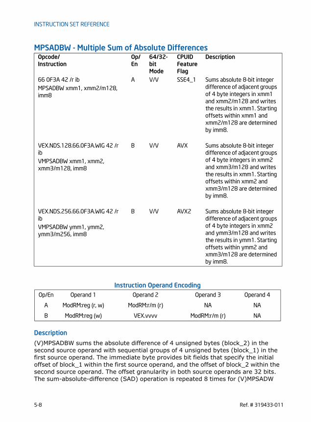
INSTRUCTION SET REFERENCE
MPSADBW - Multiple Sum of Absolute Differences
Instruction Operand Encoding
Description
(V)MPSADBW sums the absolute difference of 4 unsigned bytes (block_2) in the second source operand with sequential groups of 4 unsigned bytes (block_1) in the first source operand. The immediate byte provides bit fields that specify the initial offset of block_1 within the first source operand, and the offset of block_2 within the second source operand. The offset granularity in both source operands are 32 bits. The sum-absolute-difference (SAD) operation is repeated 8 times for (V)MPSADW
Opcode/Instruction
Op/ En
64/32-bit Mode
CPUID Feature Flag
Description
66 0F3A 42 /r ib A V/V SSE4_1 Sums absolute 8-bit integer difference of adjacent groups of 4 byte integers in xmm1 and xmm2/m128 and writes the results in xmm1. Starting offsets within xmm1 and xmm2/m128 are determined by imm8.
MPSADBW xmm1, xmm2/m128, imm8
VEX.NDS.128.66.0F3A.WIG 42 /r ib
B V/V AVX Sums absolute 8-bit integer difference of adjacent groups of 4 byte integers in xmm2 and xmm3/m128 and writes the results in xmm1. Starting offsets within xmm2 and xmm3/m128 are determined by imm8.
VMPSADBW xmm1, xmm2, xmm3/m128, imm8
VEX.NDS.256.66.0F3A.WIG 42 /r ib
B V/V AVX2 Sums absolute 8-bit integer difference of adjacent groups of 4 byte integers in xmm2 and ymm3/m128 and writes the results in ymm1. Starting offsets within ymm2 and xmm3/m128 are determined by imm8.
VMPSADBW ymm1, ymm2, ymm3/m256, imm8
Op/En Operand 1 Operand 2 Operand 3 Operand 4
A ModRM:reg (r, w) ModRM:r/m (r) NA NA
B ModRM:reg (w) VEX.vvvv ModRM:r/m (r) NA
5-8 Ref. # 319433-011

INSTRUCTION SET REFERENCE
between the same block_2 (fixed offset within the second source operand) and a variable block_1 (offset is shifted by 8 bits for each SAD operation) in the first source operand. Each 16-bit result of eight SAD operations is written to the respective word in the destination operand.128-bit Legacy SSE version: Imm8[1:0]*32 specifies the bit offset of block_2 within the second source operand. Imm[2]*32 specifies the initial bit offset of the block_1 within the first source operand. The first source operand and destination operand are the same. The first source and destination operands are XMM registers. The second source operand is either an XMM register or a 128-bit memory location. Bits (255:128) of the corresponding YMM destination register remain unchanged. Bits 7:3 of the immediate byte are ignored.VEX.128 encoded version: Imm8[1:0]*32 specifies the bit offset of block_2 within the second source operand. Imm[2]*32 specifies the initial bit offset of the block_1 within the first source operand. The first source and destination operands are XMM registers. The second source operand is either an XMM register or a 128-bit memory location. Bits (127:128) of the corresponding YMM register are zeroed. Bits 7:3 of the immediate byte are ignored.VEX.256 encoded version: The sum-absolute-difference (SAD) operation is repeated 8 times for MPSADW between the same block_2 (fixed offset within the second source operand) and a variable block_1 (offset is shifted by 8 bits for each SAD oper-ation) in the first source operand. Each 16-bit result of eight SAD operations between block_2 and block_1 is written to the respective word in the lower 128 bits of the destination operand. Additionally, VMPSADBW performs another eight SAD operations on block_4 of the second source operand and block_3 of the first source operand. (Imm8[4:3]*32 + 128) specifies the bit offset of block_4 within the second source operand. (Imm[5]*32+128) specifies the initial bit offset of the block_3 within the first source operand. Each 16-bit result of eight SAD operations between block_4 and block_3 is written to the respective word in the upper 128 bits of the destination operand. The first source operand is a YMM register. The second source register can be a YMM register or a 256-bit memory location. The destination operand is a YMM register. Bits 7:6 of the immediate byte are ignored.
Ref. # 319433-011 5-9

INSTRUCTION SET REFERENCE
Operation
VMPSADBW (VEX.256 encoded version)SRC2_OFFSET imm8[1:0]*32SRC1_OFFSET imm8[2]*32SRC1_BYTE0 SRC1[SRC1_OFFSET+7:SRC1_OFFSET]
Figure 5-1. VMPSADBW Operation
Abs. Diff.
Sum
Imm[4:3]*32+128
Imm[5]*32+128Src2
Src1
128255 144
128255 224 192
Abs. Diff.
Sum
Imm[1:0]*32
Imm[2]*32Src2
Destination
0127 16
0127 96 64
Destination
Src1
5-10 Ref. # 319433-011

INSTRUCTION SET REFERENCE
SRC1_BYTE1 SRC1[SRC1_OFFSET+15:SRC1_OFFSET+8]SRC1_BYTE2 SRC1[SRC1_OFFSET+23:SRC1_OFFSET+16]SRC1_BYTE3 SRC1[SRC1_OFFSET+31:SRC1_OFFSET+24]SRC1_BYTE4 SRC1[SRC1_OFFSET+39:SRC1_OFFSET+32]SRC1_BYTE5 SRC1[SRC1_OFFSET+47:SRC1_OFFSET+40]SRC1_BYTE6 SRC1[SRC1_OFFSET+55:SRC1_OFFSET+48]SRC1_BYTE7 SRC1[SRC1_OFFSET+63:SRC1_OFFSET+56]SRC1_BYTE8 SRC1[SRC1_OFFSET+71:SRC1_OFFSET+64]SRC1_BYTE9 SRC1[SRC1_OFFSET+79:SRC1_OFFSET+72]SRC1_BYTE10 SRC1[SRC1_OFFSET+87:SRC1_OFFSET+80]
SRC2_BYTE0 SRC2[SRC2_OFFSET+7:SRC2_OFFSET]SRC2_BYTE1 SRC2[SRC2_OFFSET+15:SRC2_OFFSET+8]SRC2_BYTE2 SRC2[SRC2_OFFSET+23:SRC2_OFFSET+16]SRC2_BYTE3 SRC2[SRC2_OFFSET+31:SRC2_OFFSET+24]
TEMP0 ABS(SRC1_BYTE0 - SRC2_BYTE0)TEMP1 ABS(SRC1_BYTE1 - SRC2_BYTE1)TEMP2 ABS(SRC1_BYTE2 - SRC2_BYTE2)TEMP3 ABS(SRC1_BYTE3 - SRC2_BYTE3)DEST[15:0] TEMP0 + TEMP1 + TEMP2 + TEMP3TEMP0 ABS(SRC1_BYTE1 - SRC2_BYTE0)TEMP1 ABS(SRC1_BYTE2 - SRC2_BYTE1)TEMP2 ABS(SRC1_BYTE3 - SRC2_BYTE2)TEMP3 ABS(SRC1_BYTE4 - SRC2_BYTE3)DEST[31:16] TEMP0 + TEMP1 + TEMP2 + TEMP3TEMP0 ABS(SRC1_BYTE2 - SRC2_BYTE0)TEMP1 ABS(SRC1_BYTE3 - SRC2_BYTE1)TEMP2 ABS(SRC1_BYTE4 - SRC2_BYTE2)TEMP3 ABS(SRC1_BYTE5 - SRC2_BYTE3)DEST[47:32] TEMP0 + TEMP1 + TEMP2 + TEMP3TEMP0 ABS(SRC1_BYTE3 - SRC2_BYTE0)TEMP1 ABS(SRC1_BYTE4 - SRC2_BYTE1)TEMP2 ABS(SRC1_BYTE5 - SRC2_BYTE2)TEMP3 ABS(SRC1_BYTE6 - SRC2_BYTE3)DEST[63:48] TEMP0 + TEMP1 + TEMP2 + TEMP3TEMP0 ABS(SRC1_BYTE4 - SRC2_BYTE0)TEMP1 ABS(SRC1_BYTE5 - SRC2_BYTE1)TEMP2 ABS(SRC1_BYTE6 - SRC2_BYTE2)TEMP3 ABS(SRC1_BYTE7 - SRC2_BYTE3)DEST[79:64] TEMP0 + TEMP1 + TEMP2 + TEMP3TEMP0 ABS(SRC1_BYTE5 - SRC2_BYTE0)TEMP1 ABS(SRC1_BYTE6 - SRC2_BYTE1)
Ref. # 319433-011 5-11

INSTRUCTION SET REFERENCE
TEMP2 ABS(SRC1_BYTE7 - SRC2_BYTE2)TEMP3 ABS(SRC1_BYTE8 - SRC2_BYTE3)DEST[95:80] TEMP0 + TEMP1 + TEMP2 + TEMP3TEMP0 ABS(SRC1_BYTE6 - SRC2_BYTE0)TEMP1 ABS(SRC1_BYTE7 - SRC2_BYTE1)TEMP2 ABS(SRC1_BYTE8 - SRC2_BYTE2)TEMP3 ABS(SRC1_BYTE9 - SRC2_BYTE3)DEST[111:96] TEMP0 + TEMP1 + TEMP2 + TEMP3
TEMP0 ABS(SRC1_BYTE7 - SRC2_BYTE0)TEMP1 ABS(SRC1_BYTE8 - SRC2_BYTE1)TEMP2 ABS(SRC1_BYTE9 - SRC2_BYTE2)TEMP3 ABS(SRC1_BYTE10 - SRC2_BYTE3)DEST[127:112] TEMP0 + TEMP1 + TEMP2 + TEMP3
SRC2_OFFSET imm8[4:3]*32 + 128SRC1_OFFSET imm8[5]*32 + 128SRC1_BYTE0 SRC1[SRC1_OFFSET+7:SRC1_OFFSET]SRC1_BYTE1 SRC1[SRC1_OFFSET+15:SRC1_OFFSET+8]SRC1_BYTE2 SRC1[SRC1_OFFSET+23:SRC1_OFFSET+16]SRC1_BYTE3 SRC1[SRC1_OFFSET+31:SRC1_OFFSET+24]SRC1_BYTE4 SRC1[SRC1_OFFSET+39:SRC1_OFFSET+32]SRC1_BYTE5 SRC1[SRC1_OFFSET+47:SRC1_OFFSET+40]SRC1_BYTE6 SRC1[SRC1_OFFSET+55:SRC1_OFFSET+48]SRC1_BYTE7 SRC1[SRC1_OFFSET+63:SRC1_OFFSET+56]SRC1_BYTE8 SRC1[SRC1_OFFSET+71:SRC1_OFFSET+64]SRC1_BYTE9 SRC1[SRC1_OFFSET+79:SRC1_OFFSET+72]SRC1_BYTE10 SRC1[SRC1_OFFSET+87:SRC1_OFFSET+80]
SRC2_BYTE0 SRC2[SRC2_OFFSET+7:SRC2_OFFSET]SRC2_BYTE1 SRC2[SRC2_OFFSET+15:SRC2_OFFSET+8]SRC2_BYTE2 SRC2[SRC2_OFFSET+23:SRC2_OFFSET+16]SRC2_BYTE3 SRC2[SRC2_OFFSET+31:SRC2_OFFSET+24]
TEMP0 ABS(SRC1_BYTE0 - SRC2_BYTE0)TEMP1 ABS(SRC1_BYTE1 - SRC2_BYTE1)TEMP2 ABS(SRC1_BYTE2 - SRC2_BYTE2)TEMP3 ABS(SRC1_BYTE3 - SRC2_BYTE3)DEST[143:128] TEMP0 + TEMP1 + TEMP2 + TEMP3TEMP0 ABS(SRC1_BYTE1 - SRC2_BYTE0)TEMP1 ABS(SRC1_BYTE2 - SRC2_BYTE1)TEMP2 ABS(SRC1_BYTE3 - SRC2_BYTE2)TEMP3 ABS(SRC1_BYTE4 - SRC2_BYTE3)
5-12 Ref. # 319433-011

INSTRUCTION SET REFERENCE
DEST[159:144] TEMP0 + TEMP1 + TEMP2 + TEMP3TEMP0 ABS(SRC1_BYTE2 - SRC2_BYTE0)TEMP1 ABS(SRC1_BYTE3 - SRC2_BYTE1)TEMP2 ABS(SRC1_BYTE4 - SRC2_BYTE2)TEMP3 ABS(SRC1_BYTE5 - SRC2_BYTE3)DEST[175:160] TEMP0 + TEMP1 + TEMP2 + TEMP3TEMP0 ABS(SRC1_BYTE3 - SRC2_BYTE0)TEMP1 ABS(SRC1_BYTE4 - SRC2_BYTE1)TEMP2 ABS(SRC1_BYTE5 - SRC2_BYTE2)TEMP3 ABS(SRC1_BYTE6 - SRC2_BYTE3)DEST[191:176] TEMP0 + TEMP1 + TEMP2 + TEMP3TEMP0 ABS(SRC1_BYTE4 - SRC2_BYTE0)TEMP1 ABS(SRC1_BYTE5 - SRC2_BYTE1)TEMP2 ABS(SRC1_BYTE6 - SRC2_BYTE2)TEMP3 ABS(SRC1_BYTE7 - SRC2_BYTE3)DEST[207:192] TEMP0 + TEMP1 + TEMP2 + TEMP3TEMP0 ABS(SRC1_BYTE5 - SRC2_BYTE0)TEMP1 ABS(SRC1_BYTE6 - SRC2_BYTE1)TEMP2 ABS(SRC1_BYTE7 - SRC2_BYTE2)TEMP3 ABS(SRC1_BYTE8 - SRC2_BYTE3)DEST[223:208] TEMP0 + TEMP1 + TEMP2 + TEMP3TEMP0 ABS(SRC1_BYTE6 - SRC2_BYTE0)TEMP1 ABS(SRC1_BYTE7 - SRC2_BYTE1)TEMP2 ABS(SRC1_BYTE8 - SRC2_BYTE2)TEMP3 ABS(SRC1_BYTE9 - SRC2_BYTE3)DEST[239:224] TEMP0 + TEMP1 + TEMP2 + TEMP3
TEMP0 ABS(SRC1_BYTE7 - SRC2_BYTE0)TEMP1 ABS(SRC1_BYTE8 - SRC2_BYTE1)TEMP2 ABS(SRC1_BYTE9 - SRC2_BYTE2)TEMP3 ABS(SRC1_BYTE10 - SRC2_BYTE3)DEST[255:240] TEMP0 + TEMP1 + TEMP2 + TEMP3
VMPSADBW (VEX.128 encoded version)SRC2_OFFSET imm8[1:0]*32SRC1_OFFSET imm8[2]*32SRC1_BYTE0 SRC1[SRC1_OFFSET+7:SRC1_OFFSET]SRC1_BYTE1 SRC1[SRC1_OFFSET+15:SRC1_OFFSET+8]SRC1_BYTE2 SRC1[SRC1_OFFSET+23:SRC1_OFFSET+16]SRC1_BYTE3 SRC1[SRC1_OFFSET+31:SRC1_OFFSET+24]SRC1_BYTE4 SRC1[SRC1_OFFSET+39:SRC1_OFFSET+32]SRC1_BYTE5 SRC1[SRC1_OFFSET+47:SRC1_OFFSET+40]SRC1_BYTE6 SRC1[SRC1_OFFSET+55:SRC1_OFFSET+48]
Ref. # 319433-011 5-13

INSTRUCTION SET REFERENCE
SRC1_BYTE7 SRC1[SRC1_OFFSET+63:SRC1_OFFSET+56]SRC1_BYTE8 SRC1[SRC1_OFFSET+71:SRC1_OFFSET+64]SRC1_BYTE9 SRC1[SRC1_OFFSET+79:SRC1_OFFSET+72]SRC1_BYTE10 SRC1[SRC1_OFFSET+87:SRC1_OFFSET+80]
SRC2_BYTE0 SRC2[SRC2_OFFSET+7:SRC2_OFFSET]SRC2_BYTE1 SRC2[SRC2_OFFSET+15:SRC2_OFFSET+8]SRC2_BYTE2 SRC2[SRC2_OFFSET+23:SRC2_OFFSET+16]SRC2_BYTE3 SRC2[SRC2_OFFSET+31:SRC2_OFFSET+24]
TEMP0 ABS(SRC1_BYTE0 - SRC2_BYTE0)TEMP1 ABS(SRC1_BYTE1 - SRC2_BYTE1)TEMP2 ABS(SRC1_BYTE2 - SRC2_BYTE2)TEMP3 ABS(SRC1_BYTE3 - SRC2_BYTE3)DEST[15:0] TEMP0 + TEMP1 + TEMP2 + TEMP3TEMP0 ABS(SRC1_BYTE1 - SRC2_BYTE0)TEMP1 ABS(SRC1_BYTE2 - SRC2_BYTE1)TEMP2 ABS(SRC1_BYTE3 - SRC2_BYTE2)TEMP3 ABS(SRC1_BYTE4 - SRC2_BYTE3)DEST[31:16] TEMP0 + TEMP1 + TEMP2 + TEMP3TEMP0 ABS(SRC1_BYTE2 - SRC2_BYTE0)TEMP1 ABS(SRC1_BYTE3 - SRC2_BYTE1)TEMP2 ABS(SRC1_BYTE4 - SRC2_BYTE2)TEMP3 ABS(SRC1_BYTE5 - SRC2_BYTE3)DEST[47:32] TEMP0 + TEMP1 + TEMP2 + TEMP3TEMP0 ABS(SRC1_BYTE3 - SRC2_BYTE0)TEMP1 ABS(SRC1_BYTE4 - SRC2_BYTE1)TEMP2 ABS(SRC1_BYTE5 - SRC2_BYTE2)TEMP3 ABS(SRC1_BYTE6 - SRC2_BYTE3)DEST[63:48] TEMP0 + TEMP1 + TEMP2 + TEMP3TEMP0 ABS(SRC1_BYTE4 - SRC2_BYTE0)TEMP1 ABS(SRC1_BYTE5 - SRC2_BYTE1)TEMP2 ABS(SRC1_BYTE6 - SRC2_BYTE2)TEMP3 ABS(SRC1_BYTE7 - SRC2_BYTE3)DEST[79:64] TEMP0 + TEMP1 + TEMP2 + TEMP3TEMP0 ABS(SRC1_BYTE5 - SRC2_BYTE0)TEMP1 ABS(SRC1_BYTE6 - SRC2_BYTE1)TEMP2 ABS(SRC1_BYTE7 - SRC2_BYTE2)TEMP3 ABS(SRC1_BYTE8 - SRC2_BYTE3)DEST[95:80] TEMP0 + TEMP1 + TEMP2 + TEMP3TEMP0 ABS(SRC1_BYTE6 - SRC2_BYTE0)TEMP1 ABS(SRC1_BYTE7 - SRC2_BYTE1)TEMP2 ABS(SRC1_BYTE8 - SRC2_BYTE2)
5-14 Ref. # 319433-011

INSTRUCTION SET REFERENCE
TEMP3 ABS(SRC1_BYTE9 - SRC2_BYTE3)DEST[111:96] TEMP0 + TEMP1 + TEMP2 + TEMP3
TEMP0 ABS(SRC1_BYTE7 - SRC2_BYTE0)TEMP1 ABS(SRC1_BYTE8 - SRC2_BYTE1)TEMP2 ABS(SRC1_BYTE9 - SRC2_BYTE2)TEMP3 ABS(SRC1_BYTE10 - SRC2_BYTE3)DEST[127:112] TEMP0 + TEMP1 + TEMP2 + TEMP3
DEST[VLMAX:128] 0
MPSADBW (128-bit Legacy SSE version)SRC_OFFSET imm8[1:0]*32DEST_OFFSET imm8[2]*32DEST_BYTE0 DEST[DEST_OFFSET+7:DEST_OFFSET]DEST_BYTE1 DEST[DEST_OFFSET+15:DEST_OFFSET+8]DEST_BYTE2 DEST[DEST_OFFSET+23:DEST_OFFSET+16]DEST_BYTE3 DEST[DEST_OFFSET+31:DEST_OFFSET+24]DEST_BYTE4 DEST[DEST_OFFSET+39:DEST_OFFSET+32]DEST_BYTE5 DEST[DEST_OFFSET+47:DEST_OFFSET+40]DEST_BYTE6 DEST[DEST_OFFSET+55:DEST_OFFSET+48]DEST_BYTE7 DEST[DEST_OFFSET+63:DEST_OFFSET+56]DEST_BYTE8 DEST[DEST_OFFSET+71:DEST_OFFSET+64]DEST_BYTE9 DEST[DEST_OFFSET+79:DEST_OFFSET+72]DEST_BYTE10 DEST[DEST_OFFSET+87:DEST_OFFSET+80]
SRC_BYTE0 SRC[SRC_OFFSET+7:SRC_OFFSET]SRC_BYTE1 SRC[SRC_OFFSET+15:SRC_OFFSET+8]SRC_BYTE2 SRC[SRC_OFFSET+23:SRC_OFFSET+16]SRC_BYTE3 SRC[SRC_OFFSET+31:SRC_OFFSET+24]
TEMP0 ABS(DEST_BYTE0 - SRC_BYTE0)TEMP1 ABS(DEST_BYTE1 - SRC_BYTE1)TEMP2 ABS(DEST_BYTE2 - SRC_BYTE2)TEMP3 ABS(DEST_BYTE3 - SRC_BYTE3)DEST[15:0] TEMP0 + TEMP1 + TEMP2 + TEMP3TEMP0 ABS(DEST_BYTE1 - SRC_BYTE0)TEMP1 ABS(DEST_BYTE2 - SRC_BYTE1)TEMP2 ABS(DEST_BYTE3 - SRC_BYTE2)TEMP3 ABS(DEST_BYTE4 - SRC_BYTE3)DEST[31:16] TEMP0 + TEMP1 + TEMP2 + TEMP3TEMP0 ABS(DEST_BYTE2 - SRC_BYTE0)TEMP1 ABS(DEST_BYTE3 - SRC_BYTE1)
Ref. # 319433-011 5-15

INSTRUCTION SET REFERENCE
TEMP2 ABS(DEST_BYTE4 - SRC_BYTE2)TEMP3 ABS(DEST_BYTE5 - SRC_BYTE3)DEST[47:32] TEMP0 + TEMP1 + TEMP2 + TEMP3TEMP0 ABS(DEST_BYTE3 - SRC_BYTE0)TEMP1 ABS(DEST_BYTE4 - SRC_BYTE1)TEMP2 ABS(DEST_BYTE5 - SRC_BYTE2)TEMP3 ABS(DEST_BYTE6 - SRC_BYTE3)DEST[63:48] TEMP0 + TEMP1 + TEMP2 + TEMP3TEMP0 ABS(DEST_BYTE4 - SRC_BYTE0)TEMP1 ABS(DEST_BYTE5 - SRC_BYTE1)TEMP2 ABS(DEST_BYTE6 - SRC_BYTE2)TEMP3 ABS(DEST_BYTE7 - SRC_BYTE3)DEST[79:64] TEMP0 + TEMP1 + TEMP2 + TEMP3TEMP0 ABS(DEST_BYTE5 - SRC_BYTE0)TEMP1 ABS(DEST_BYTE6 - SRC_BYTE1)TEMP2 ABS(DEST_BYTE7 - SRC_BYTE2)TEMP3 ABS(DEST_BYTE8 - SRC_BYTE3)DEST[95:80] TEMP0 + TEMP1 + TEMP2 + TEMP3TEMP0 ABS(DEST_BYTE6 - SRC_BYTE0)TEMP1 ABS(DEST_BYTE7 - SRC_BYTE1)TEMP2 ABS(DEST_BYTE8 - SRC_BYTE2)TEMP3 ABS(DEST_BYTE9 - SRC_BYTE3)DEST[111:96] TEMP0 + TEMP1 + TEMP2 + TEMP3
TEMP0 ABS(DEST_BYTE7 - SRC_BYTE0)TEMP1 ABS(DEST_BYTE8 - SRC_BYTE1)TEMP2 ABS(DEST_BYTE9 - SRC_BYTE2)TEMP3 ABS(DEST_BYTE10 - SRC_BYTE3)DEST[127:112] TEMP0 + TEMP1 + TEMP2 + TEDEST[VLMAX:128] (Unmodified)
Intel C/C++ Compiler Intrinsic Equivalent
(V)MPSADBW __m128i _mm_mpsadbw_epu8 (__m128i s1, __m128i s2, const int mask);
VMPSADBW __m256i _mm256_mpsadbw_epu8 (__m256i s1, __m256i s2, const int mask);
SIMD Floating-Point Exceptions
None
Other ExceptionsSee Exceptions Type 4
5-16 Ref. # 319433-011

INSTRUCTION SET REFERENCE
PABSB/PABSW/PABSD — Packed Absolute Value Opcode/Instruction
Op/ En
64/32-bit Mode
CPUID Feature Flag
Description
66 0F 38 1C /r A V/V SSSE3 Compute the absolute value of bytes in xmm2/m128 and store UNSIGNED result in xmm1.
PABSB xmm1, xmm2/m128
66 0F 38 1D /r A V/V SSSE3 Compute the absolute value of 16-bit integers in xmm2/m128 and store UNSIGNED result in xmm1.
PABSW xmm1, xmm2/m128
66 0F 38 1E /r A V/V SSSE3 Compute the absolute value of 32-bit integers in xmm2/m128 and store UNSIGNED result in xmm1.
PABSD xmm1, xmm2/m128
VEX.128.66.0F38.WIG 1C /r A V/V AVX Compute the absolute value of bytes in xmm2/m128 and store UNSIGNED result in xmm1.
VPABSB xmm1, xmm2/m128
VEX.128.66.0F38.WIG 1D /r A V/V AVX Compute the absolute value of 16-bit integers in xmm2/m128 and store UNSIGNED result in xmm1.
VPABSW xmm1, xmm2/m128
VEX.128.66.0F38.WIG 1E /r A V/V AVX Compute the absolute value of 32-bit integers in xmm2/m128 and store UNSIGNED result in xmm1.
VPABSD xmm1, xmm2/m128
VEX.256.66.0F38.WIG 1C /r A V/V AVX2 Compute the absolute value of bytes in ymm2/m256 and store UNSIGNED result in ymm1.
VPABSB ymm1, ymm2/m256
Ref. # 319433-011 5-17

INSTRUCTION SET REFERENCE
Instruction Operand Encoding
Description
(V)PABSB/W/D computes the absolute value of each data element of the source operand (the second operand) and stores the UNSIGNED results in the destination operand (the first operand). (V)PABSB operates on signed bytes, (V)PABSW operates on 16-bit words, and (V)PABSD operates on signed 32-bit integers. The source operand can be an XMM register or a YMM register or a 128-bit memory location or 256-bit memory location. The destination operand can be an XMM or a YMM register. Both operands can be MMX register or XMM registers. VEX.256 encoded version: The first source operand is a YMM register or a 256-bit memory location. The destination operand is a YMM register. VEX.128 encoded version: The source operand is an XMM register or 128-bit memory location. The destination operand is an XMM register. The upper bits (255:128) of the corresponding YMM register destination are zeroed.128-bit Legacy SSE version: The source operand can be an XMM register or a 128-bit memory location. The destination is not distinct from the first source XMM register and the upper bits (255:128) of the corresponding YMM register destination are unmodified.
Operation
PABSB with 128 bit operands:Unsigned DEST[7:0] ABS(SRC[7:.0]) Repeat operation for 2nd through 15th bytes Unsigned DEST[127:120] ABS(SRC[127:120])
VEX.256.66.0F38.WIG 1D /r A V/V AVX2 Compute the absolute value of 16-bit integers in ymm2/m256 and store UNSIGNED result in ymm1.
VPABSW ymm1, ymm2/m256
VEX.256.66.0F38.WIG 1E /r A V/V AVX2 Compute the absolute value of 32-bit integers in ymm2/m256 and store UNSIGNED result in ymm1.
VPABSD ymm1, ymm2/m256
Op/En Operand 1 Operand 2 Operand 3 Operand 4
A ModRM:reg (w) ModRM:r/m (r) NA NA
Opcode/Instruction
Op/ En
64/32-bit Mode
CPUID Feature Flag
Description
5-18 Ref. # 319433-011

INSTRUCTION SET REFERENCE
VPABSB with 128 bit operands:Unsigned DEST[7:0] ABS(SRC[7:.0]) Repeat operation for 2nd through 15th bytes Unsigned DEST[127:120] ABS(SRC[127:120])
VPABSB with 256 bit operands:Unsigned DEST[7:0] ABS(SRC[7:.0]) Repeat operation for 2nd through 31st bytes Unsigned DEST[255:248] ABS(SRC[255:248])
PABSW with 128 bit operands:Unsigned DEST[15:0] ABS(SRC[15:0]) Repeat operation for 2nd through 7th 16-bit words Unsigned DEST[127:112] ABS(SRC[127:112])
VPABSW with 128 bit operands:Unsigned DEST[15:0] ABS(SRC[15:0]) Repeat operation for 2nd through 7th 16-bit words Unsigned DEST[127:112] ABS(SRC[127:112])
VPABSW with 256 bit operands:Unsigned DEST[15:0] ABS(SRC[15:0]) Repeat operation for 2nd through 15th 16-bit words Unsigned DEST[255:240] ABS(SRC[255:240])
PABSD with 128 bit operands:Unsigned DEST[31:0] ABS(SRC[31:0]) Repeat operation for 2nd through 3rd 32-bit double words Unsigned DEST[127:96] ABS(SRC[127:96])
VPABSD with 128 bit operands:Unsigned DEST[31:0] ABS(SRC[31:0]) Repeat operation for 2nd through 3rd 32-bit double words Unsigned DEST[127:96] ABS(SRC[127:96])
VPABSD with 256 bit operands:Unsigned DEST[31:0] ABS(SRC[31:0]) Repeat operation for 2nd through 7th 32-bit double words Unsigned DEST[255:224] ABS(SRC[255:224])
Intel C/C++ Compiler Intrinsic Equivalent
PABSB__m128i _mm_abs_epi8 (__m128i a)
Ref. # 319433-011 5-19

INSTRUCTION SET REFERENCE
VPABSB__m128i _mm_abs_epi8 (__m128i a)
VPABSB__m256i _mm256_abs_epi8 (__m256i a)
PABSW__m128i _mm_abs_epi16 (__m128i a)
VPABSW__m128i _mm_abs_epi16 (__m128i a)
VPABSW__m256i _mm256_abs_epi16 (__m256i a)
PABSD__m128i _mm_abs_epi32 (__m128i a)
VPABSD__m128i _mm_abs_epi32 (__m128i a)
VPABSD__m256i _mm256_abs_epi32 (__m256i a)
SIMD Floating-Point Exceptions
None
Other Exceptions
See Exceptions Type 4
5-20 Ref. # 319433-011

INSTRUCTION SET REFERENCE
PACKSSWB/PACKSSDW—Pack with Signed Saturation Opcode/Instruction
Op/ En
64/32-bit Mode
CPUID Feature Flag
Description
66 0F 63 /r A V/V SSE2 Converts 8 packed signed word integers from xmm1 and from xxm2/m128 into 16 packed signed byte integers in xmm1 using signed saturation.
PACKSSWB xmm1, xmm2/m128
66 0F 6B /r A V/V SSE2 Converts 4 packed signed dou-bleword integers from xmm1 and from xmm2/m128 into 8 packed signed word integers in xmm1using signed saturation.
PACKSSDW xmm1, xmm2/m128
VEX.NDS.128.66.0F.WIG 63 /r B V/V AVX Converts 8 packed signed word integers from xmm2 and from xmm3/m128 into 16 packed signed byte integers in xmm1 using signed saturation.
VPACKSSWB xmm1, xmm2, xmm3/m128
VEX.NDS.128.66.0F.WIG 6B /r B V/V AVX Converts 4 packed signed dou-bleword integers from xmm2 and from xmm3/m128 into 8 packed signed word integers in xmm1using signed saturation.
VPACKSSDW xmm1, xmm2, xmm3/m128
VEX.NDS.256.66.0F.WIG 63 /r B V/V AVX2 Converts 16 packed signed word integers from ymm2 and from ymm3/m256 into 32 packed signed byte integers in ymm1 using signed saturation.
VPACKSSWB ymm1, ymm2, ymm3/m256
VEX.NDS.256.66.0F.WIG 6B /r B V/V AVX2 Converts 8 packed signed dou-bleword integers from ymm2 and from ymm3/m256 into 16 packed signed word integers in ymm1using signed saturation.
VPACKSSDW ymm1, ymm2, ymm3/m256
Ref. # 319433-011 5-21

INSTRUCTION SET REFERENCE
Instruction Operand Encoding
Description
The PACKSSWB or VPACKSSWB instruction converts 8 or 16 signed word integers from the first source operand and 8 or 16 signed word integers from the second source operand into 16 or 32 signed byte integers and stores the result in the desti-nation operand. If a signed word integer value is beyond the range of a signed byte integer (that is, greater than 7FH for a positive integer or greater than 80H for a negative integer), the saturated signed byte integer value of 7FH or 80H, respec-tively, is stored in the destination.
The PACKSSDW instruction packs 4 or 8 signed doublewords from the first source operand and 4 or 8 signed doublewords from the second source operand into 8 or 16 signed words in the destination operand. If a signed doubleword integer value is beyond the range of a signed word (that is, greater than 7FFFH for a positive integer or greater than 8000H for a negative integer), the saturated signed word integer value of 7FFFH or 8000H, respectively, is stored into the destination.VEX.256 encoded version: The first source operand is a YMM register. The second source operand is a YMM register or a 256-bit memory location. The destination operand is a YMM register. VEX.128 encoded version: The first source operand is an XMM register. The second source operand is an XMM register or 128-bit memory location. The destination operand is an XMM register. The upper bits (255:128) of the corresponding YMM register destination are zeroed.128-bit Legacy SSE version: The first source operand is an XMM register. The second operand can be an XMM register or a 128-bit memory location. The destination is not distinct from the first source XMM register and the upper bits (255:128) of the corre-sponding YMM register destination are unmodified.
Operation
PACKSSWB instruction (128-bit Legacy SSE version)DEST[7:0] SaturateSignedWordToSignedByte (DEST[15:0]);DEST[15:8] SaturateSignedWordToSignedByte (DEST[31:16]); DEST[23:16] SaturateSignedWordToSignedByte (DEST[47:32]);DEST[31:24] SaturateSignedWordToSignedByte (DEST[63:48]);DEST[39:32] SaturateSignedWordToSignedByte (DEST[79:64]);DEST[47:40] SaturateSignedWordToSignedByte (DEST[95:80]);DEST[55:48] SaturateSignedWordToSignedByte (DEST[111:96]);DEST[63:56] SaturateSignedWordToSignedByte (DEST[127:112]);DEST[71:64] SaturateSignedWordToSignedByte (SRC[15:0]);
Op/En Operand 1 Operand 2 Operand 3 Operand 4
A ModRM:reg (r, w) ModRM:r/m (r) NA NA
B ModRM:reg (w) VEX.vvvv ModRM:r/m (r) NA
5-22 Ref. # 319433-011

INSTRUCTION SET REFERENCE
DEST[79:72] SaturateSignedWordToSignedByte (SRC[31:16]);DEST[87:80] SaturateSignedWordToSignedByte (SRC[47:32]);DEST[95:88] SaturateSignedWordToSignedByte (SRC[63:48]);DEST[103:96] SaturateSignedWordToSignedByte (SRC[79:64]);DEST[111:104] SaturateSignedWordToSignedByte (SRC[95:80]);DEST[119:112] SaturateSignedWordToSignedByte (SRC[111:96]);DEST[127:120] SaturateSignedWordToSignedByte (SRC[127:112]);
PACKSSDW instruction (128-bit Legacy SSE version)DEST[15:0] SaturateSignedDwordToSignedWord (DEST[31:0]);DEST[31:16] SaturateSignedDwordToSignedWord (DEST[63:32]);DEST[47:32] SaturateSignedDwordToSignedWord (DEST[95:64]);DEST[63:48] SaturateSignedDwordToSignedWord (DEST[127:96]);DEST[79:64] SaturateSignedDwordToSignedWord (SRC[31:0]);DEST[95:80] SaturateSignedDwordToSignedWord (SRC[63:32]);DEST[111:96] SaturateSignedDwordToSignedWord (SRC[95:64]);DEST[127:112] SaturateSignedDwordToSignedWord (SRC[127:96]);
VPACKSSWB instruction (VEX.128 encoded version)DEST[7:0] SaturateSignedWordToSignedByte (SRC1[15:0]);DEST[15:8] SaturateSignedWordToSignedByte (SRC1[31:16]); DEST[23:16] SaturateSignedWordToSignedByte (SRC1[47:32]);DEST[31:24] SaturateSignedWordToSignedByte (SRC1[63:48]);DEST[39:32] SaturateSignedWordToSignedByte (SRC1[79:64]);DEST[47:40] SaturateSignedWordToSignedByte (SRC1[95:80]);DEST[55:48] SaturateSignedWordToSignedByte (SRC1[111:96]);DEST[63:56] SaturateSignedWordToSignedByte (SRC1[127:112]);DEST[71:64] SaturateSignedWordToSignedByte (SRC2[15:0]);DEST[79:72] SaturateSignedWordToSignedByte (SRC2[31:16]);DEST[87:80] SaturateSignedWordToSignedByte (SRC2[47:32]);DEST[95:88] SaturateSignedWordToSignedByte (SRC2[63:48]);DEST[103:96] SaturateSignedWordToSignedByte (SRC2[79:64]);DEST[111:104] SaturateSignedWordToSignedByte (SRC2[95:80]);DEST[119:112] SaturateSignedWordToSignedByte (SRC2[111:96]);DEST[127:120] SaturateSignedWordToSignedByte (SRC2[127:112]);DEST[VLMAX:128] 0;
VPACKSSDW instruction (VEX.128 encoded version)DEST[15:0] SaturateSignedDwordToSignedWord (SRC1[31:0]);DEST[31:16] SaturateSignedDwordToSignedWord (SRC1[63:32]);DEST[47:32] SaturateSignedDwordToSignedWord (SRC1[95:64]);DEST[63:48] SaturateSignedDwordToSignedWord (SRC1[127:96]);DEST[79:64] SaturateSignedDwordToSignedWord (SRC2[31:0]);
Ref. # 319433-011 5-23

INSTRUCTION SET REFERENCE
DEST[95:80] SaturateSignedDwordToSignedWord (SRC2[63:32]);DEST[111:96] SaturateSignedDwordToSignedWord (SRC2[95:64]);DEST[127:112] SaturateSignedDwordToSignedWord (SRC2[127:96]);DEST[VLMAX:128] 0;
VPACKSSWB instruction (VEX.256 encoded version)DEST[7:0] SaturateSignedWordToSignedByte (SRC1[15:0]);DEST[15:8] SaturateSignedWordToSignedByte (SRC1[31:16]); DEST[23:16] SaturateSignedWordToSignedByte (SRC1[47:32]);DEST[31:24] SaturateSignedWordToSignedByte (SRC1[63:48]);DEST[39:32] SaturateSignedWordToSignedByte (SRC1[79:64]);DEST[47:40] SaturateSignedWordToSignedByte (SRC1[95:80]);DEST[55:48] SaturateSignedWordToSignedByte (SRC1[111:96]);DEST[63:56] SaturateSignedWordToSignedByte (SRC1[127:112]);DEST[71:64] SaturateSignedWordToSignedByte (SRC2[15:0]);DEST[79:72] SaturateSignedWordToSignedByte (SRC2[31:16]);DEST[87:80] SaturateSignedWordToSignedByte (SRC2[47:32]);DEST[95:88] SaturateSignedWordToSignedByte (SRC2[63:48]);DEST[103:96] SaturateSignedWordToSignedByte (SRC2[79:64]);DEST[111:104] SaturateSignedWordToSignedByte (SRC2[95:80]);DEST[119:112] SaturateSignedWordToSignedByte (SRC2[111:96]);DEST[127:120] SaturateSignedWordToSignedByte (SRC2[127:112]);DEST[135:128] SaturateSignedWordToSignedByte (SRC1[143:128]);DEST[143:136] SaturateSignedWordToSignedByte (SRC1[159:144]); DEST[151:144] SaturateSignedWordToSignedByte (SRC1[175:160]);DEST[159:152] SaturateSignedWordToSignedByte (SRC1[191:176]);DEST[167:160] SaturateSignedWordToSignedByte (SRC1[207:192]);DEST[175:168] SaturateSignedWordToSignedByte (SRC1[223:208]);DEST[183:176] SaturateSignedWordToSignedByte (SRC1[239:224]);DEST[191:184] SaturateSignedWordToSignedByte (SRC1[255:240]);DEST[199:192] SaturateSignedWordToSignedByte (SRC2[143:128]);DEST[207:200] SaturateSignedWordToSignedByte (SRC2[159:144]);DEST[215:208] SaturateSignedWordToSignedByte (SRC2[175:160]);DEST[223:216] SaturateSignedWordToSignedByte (SRC2[191:176]);DEST[231:224] SaturateSignedWordToSignedByte (SRC2[207:192]);DEST[239:232] SaturateSignedWordToSignedByte (SRC2[223:208]);DEST[247:240] SaturateSignedWordToSignedByte (SRC2[239:224]);DEST[255:248] SaturateSignedWordToSignedByte (SRC2[255:240]);
VPACKSSDW instruction (VEX.256 encoded version)DEST[15:0] SaturateSignedDwordToSignedWord (SRC1[31:0]);DEST[31:16] SaturateSignedDwordToSignedWord (SRC1[63:32]);DEST[47:32] SaturateSignedDwordToSignedWord (SRC1[95:64]);
5-24 Ref. # 319433-011

INSTRUCTION SET REFERENCE
DEST[63:48] SaturateSignedDwordToSignedWord (SRC1[127:96]);DEST[79:64] SaturateSignedDwordToSignedWord (SRC2[31:0]);DEST[95:80] SaturateSignedDwordToSignedWord (SRC2[63:32]);DEST[111:96] SaturateSignedDwordToSignedWord (SRC2[95:64]);DEST[127:112] SaturateSignedDwordToSignedWord (SRC2[127:96]);DEST[143:128] SaturateSignedDwordToSignedWord (SRC1[159:128]);DEST[159:144] SaturateSignedDwordToSignedWord (SRC1[191:160]);DEST[175:160] SaturateSignedDwordToSignedWord (SRC1[223:192]);DEST[191:176] SaturateSignedDwordToSignedWord (SRC1[255:224]);DEST[207:192] SaturateSignedDwordToSignedWord (SRC2[159:128]);DEST[223:208] SaturateSignedDwordToSignedWord (SRC2[191:160]);DEST[239:224] SaturateSignedDwordToSignedWord (SRC2[223:192]);DEST[255:240] SaturateSignedDwordToSignedWord (SRC2[255:224]);
Intel C/C++ Compiler Intrinsic Equivalent
(V)PACKSSWB __m128i _mm_packs_epi16(__m128i m1, __m128i m2)
(V)PACKSSDW __m128i _mm_packs_epi32(__m128i m1, __m128i m2)
VPACKSSWB __m256i _mm256_packs_epi16(__m256i m1, __m256i m2)
VPACKSSDW __m256i _mm256_packs_epi32(__m256i m1, __m256i m2)
SIMD Floating-Point Exceptions
None
Other Exceptions
See Exceptions Type 4
Ref. # 319433-011 5-25

INSTRUCTION SET REFERENCE
PACKUSDW — Pack with Unsigned Saturation
Instruction Operand Encoding
Description
Converts packed signed doubleword integers into packed unsigned word integers using unsigned saturation to handle overflow conditions. If the signed doubleword value is beyond the range of an unsigned word (that is, greater than FFFFH or less than 0000H), the saturated unsigned word integer value of FFFFH or 0000H, respec-tively, is stored in the destination.
Opcode/Instruction
Op/ En
64/32-bit Mode
CPUID Feature Flag
Description
66 0F 38 2B /r A V/V SSE4_1 Convert 4 packed signed dou-bleword integers from xmm1 and 4 packed signed double-word integers from xmm2/m128 into 8 packed unsigned word integers in xmm1 using unsigned satura-tion.
PACKUSDW xmm1, xmm2/m128
VEX.NDS.128.66.0F38.WIG 2B /r B V/V AVX Convert 4 packed signed dou-bleword integers from xmm2 and 4 packed signed double-word integers from xmm3/m128 into 8 packed unsigned word integers in xmm1 using unsigned satura-tion.
VPACKUSDW xmm1,xmm2, xmm3/m128
VEX.NDS.256.66.0F38.WIG 2B /r B V/V AVX2 Convert 8 packed signed dou-bleword integers from ymm2 and 8 packed signed double-word integers from ymm3/m128 into 16 packed unsigned word integers in ymm1 using unsigned satura-tion.
VPACKUSDW ymm1, ymm2, ymm3/m256
Op/En Operand 1 Operand 2 Operand 3 Operand 4
A ModRM:reg (r, w) ModRM:r/m (r) NA NA
B ModRM:reg (w) VEX.vvvv ModRM:r/m (r) NA
5-26 Ref. # 319433-011

INSTRUCTION SET REFERENCE
VEX.256 encoded version: The first source operand is a YMM register. The second source operand is a YMM register or a 256-bit memory location. The destination operand is a YMM register. VEX.128 encoded version: The first source operand is an XMM register. The second source operand is an XMM register or 128-bit memory location. The destination operand is an XMM register. The upper bits (255:128) of the corresponding YMM register destination are zeroed.128-bit Legacy SSE version: The first source operand is an XMM register. The second operand can be an XMM register or a 128-bit memory location. The destination is not distinct from the first source XMM register and the upper bits (255:128) of the corre-sponding YMM register destination are unmodified.
Operation
PACKUSDW (Legacy SSE instruction)TMP[15:0] (DEST[31:0] < 0) ? 0 : DEST[15:0];DEST[15:0] (DEST[31:0] > FFFFH) ? FFFFH : TMP[15:0] ;TMP[31:16] (DEST[63:32] < 0) ? 0 : DEST[47:32];DEST[31:16] (DEST[63:32] > FFFFH) ? FFFFH : TMP[31:16] ;TMP[47:32] (DEST[95:64] < 0) ? 0 : DEST[79:64];DEST[47:32] (DEST[95:64] > FFFFH) ? FFFFH : TMP[47:32] ;TMP[63:48] (DEST[127:96] < 0) ? 0 : DEST[111:96];DEST[63:48] (DEST[127:96] > FFFFH) ? FFFFH : TMP[63:48] ;TMP[79:64] (SRC[31:0] < 0) ? 0 : SRC[15:0];DEST[63:48] (SRC[31:0] > FFFFH) ? FFFFH : TMP[79:64] ;TMP[95:80] (SRC[63:32] < 0) ? 0 : SRC[47:32];DEST[95:80] (SRC[63:32] > FFFFH) ? FFFFH : TMP[95:80] ;TMP[111:96] (SRC[95:64] < 0) ? 0 : SRC[79:64];DEST[111:96] (SRC[95:64] > FFFFH) ? FFFFH : TMP[111:96] ;TMP[127:112] (SRC[127:96] < 0) ? 0 : SRC[111:96];DEST[127:112] (SRC[127:96] > FFFFH) ? FFFFH : TMP[127:112] ;
PACKUSDW (VEX.128 encoded version)TMP[15:0] (SRC1[31:0] < 0) ? 0 : SRC1[15:0];DEST[15:0] (SRC1[31:0] > FFFFH) ? FFFFH : TMP[15:0] ;TMP[31:16] (SRC1[63:32] < 0) ? 0 : SRC1[47:32];DEST[31:16] (SRC1[63:32] > FFFFH) ? FFFFH : TMP[31:16] ;TMP[47:32] (SRC1[95:64] < 0) ? 0 : SRC1[79:64];DEST[47:32] (SRC1[95:64] > FFFFH) ? FFFFH : TMP[47:32] ;TMP[63:48] (SRC1[127:96] < 0) ? 0 : SRC1[111:96];DEST[63:48] (SRC1[127:96] > FFFFH) ? FFFFH : TMP[63:48] ;TMP[79:64] (SRC2[31:0] < 0) ? 0 : SRC2[15:0];DEST[63:48] (SRC2[31:0] > FFFFH) ? FFFFH : TMP[79:64] ;TMP[95:80] (SRC2[63:32] < 0) ? 0 : SRC2[47:32];
Ref. # 319433-011 5-27
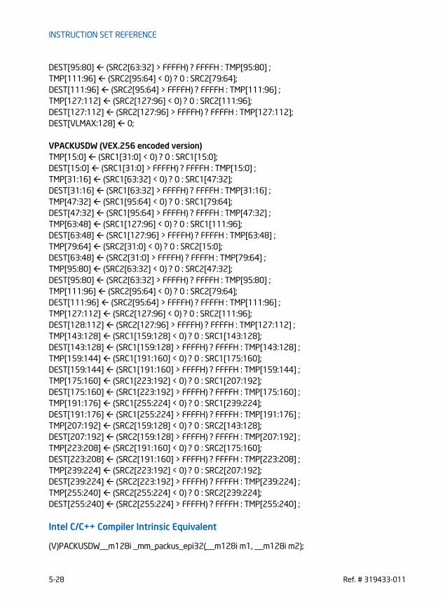
INSTRUCTION SET REFERENCE
DEST[95:80] (SRC2[63:32] > FFFFH) ? FFFFH : TMP[95:80] ;TMP[111:96] (SRC2[95:64] < 0) ? 0 : SRC2[79:64];DEST[111:96] (SRC2[95:64] > FFFFH) ? FFFFH : TMP[111:96] ;TMP[127:112] (SRC2[127:96] < 0) ? 0 : SRC2[111:96];DEST[127:112] (SRC2[127:96] > FFFFH) ? FFFFH : TMP[127:112];DEST[VLMAX:128] 0;
VPACKUSDW (VEX.256 encoded version)TMP[15:0] (SRC1[31:0] < 0) ? 0 : SRC1[15:0];DEST[15:0] (SRC1[31:0] > FFFFH) ? FFFFH : TMP[15:0] ;TMP[31:16] (SRC1[63:32] < 0) ? 0 : SRC1[47:32];DEST[31:16] (SRC1[63:32] > FFFFH) ? FFFFH : TMP[31:16] ;TMP[47:32] (SRC1[95:64] < 0) ? 0 : SRC1[79:64];DEST[47:32] (SRC1[95:64] > FFFFH) ? FFFFH : TMP[47:32] ;TMP[63:48] (SRC1[127:96] < 0) ? 0 : SRC1[111:96];DEST[63:48] (SRC1[127:96] > FFFFH) ? FFFFH : TMP[63:48] ;TMP[79:64] (SRC2[31:0] < 0) ? 0 : SRC2[15:0];DEST[63:48] (SRC2[31:0] > FFFFH) ? FFFFH : TMP[79:64] ;TMP[95:80] (SRC2[63:32] < 0) ? 0 : SRC2[47:32];DEST[95:80] (SRC2[63:32] > FFFFH) ? FFFFH : TMP[95:80] ;TMP[111:96] (SRC2[95:64] < 0) ? 0 : SRC2[79:64];DEST[111:96] (SRC2[95:64] > FFFFH) ? FFFFH : TMP[111:96] ;TMP[127:112] (SRC2[127:96] < 0) ? 0 : SRC2[111:96];DEST[128:112] (SRC2[127:96] > FFFFH) ? FFFFH : TMP[127:112] ;TMP[143:128] (SRC1[159:128] < 0) ? 0 : SRC1[143:128];DEST[143:128] (SRC1[159:128] > FFFFH) ? FFFFH : TMP[143:128] ;TMP[159:144] (SRC1[191:160] < 0) ? 0 : SRC1[175:160];DEST[159:144] (SRC1[191:160] > FFFFH) ? FFFFH : TMP[159:144] ;TMP[175:160] (SRC1[223:192] < 0) ? 0 : SRC1[207:192];DEST[175:160] (SRC1[223:192] > FFFFH) ? FFFFH : TMP[175:160] ;TMP[191:176] (SRC1[255:224] < 0) ? 0 : SRC1[239:224];DEST[191:176] (SRC1[255:224] > FFFFH) ? FFFFH : TMP[191:176] ;TMP[207:192] (SRC2[159:128] < 0) ? 0 : SRC2[143:128];DEST[207:192] (SRC2[159:128] > FFFFH) ? FFFFH : TMP[207:192] ;TMP[223:208] (SRC2[191:160] < 0) ? 0 : SRC2[175:160];DEST[223:208] (SRC2[191:160] > FFFFH) ? FFFFH : TMP[223:208] ;TMP[239:224] (SRC2[223:192] < 0) ? 0 : SRC2[207:192];DEST[239:224] (SRC2[223:192] > FFFFH) ? FFFFH : TMP[239:224] ;TMP[255:240] (SRC2[255:224] < 0) ? 0 : SRC2[239:224];DEST[255:240] (SRC2[255:224] > FFFFH) ? FFFFH : TMP[255:240] ;
Intel C/C++ Compiler Intrinsic Equivalent
(V)PACKUSDW__m128i _mm_packus_epi32(__m128i m1, __m128i m2);
5-28 Ref. # 319433-011

INSTRUCTION SET REFERENCE
VPACKUSDW__m256i _mm256_packus_epi32(__m256i m1, __m256i m2);
SIMD Floating-Point Exceptions
None
Other Exceptions
See Exceptions Type 4
Ref. # 319433-011 5-29

INSTRUCTION SET REFERENCE
PACKUSWB — Pack with Unsigned Saturation
Instruction Operand Encoding
Description
Converts 8 or 16 signed word integers from the first source operand and 8 or 16 signed word integers from the second source operand into 16 or 32 unsigned byte integers and stores the result in the destination operand. If a signed word integer value is beyond the range of an unsigned byte integer (that is, greater than FFH or less than 00H), the saturated unsigned byte integer value of FFH or 00H, respec-tively, is stored in the destination.VEX.256 encoded version: The first source operand is a YMM register. The second source operand is a YMM register or a 256-bit memory location. The destination operand is a YMM register. VEX.128 encoded version: The first source operand is an XMM register. The second source operand is an XMM register or 128-bit memory location. The destination
Opcode/Instruction
Op/ En
64/32-bit Mode
CPUID Feature Flag
Description
66 0F 67 /r A V/V SSE2 Converts 8 signed word integers from xmm1 and 8 signed word integers from xmm2/m128 into 16 unsigned byte integers in xmm1 using unsigned satura-tion.
PACKUSWB xmm1, xmm2/m128
VEX.NDS.128.66.0F.WIG 67 /r B V/V AVX Converts 8 signed word integers from xmm2 and 8 signed word integers from xmm3/m128 into 16 unsigned byte integers in xmm1 using unsigned satura-tion.
VPACKUSWB xmm1,xmm2, xmm3/m128
VEX.NDS.256.66.0F.WIG 67 /r B V/V AVX2 Converts 16 signed word inte-gers from ymm2 and 16signed word integers from ymm3/m256 into 32 unsigned byte integers in ymm1 using unsigned saturation.
VPACKUSWB ymm1, ymm2, ymm3/m256
Op/En Operand 1 Operand 2 Operand 3 Operand 4
A ModRM:reg (r, w) ModRM:r/m (r) NA NA
B ModRM:reg (w) VEX.vvvv ModRM:r/m (r) NA
5-30 Ref. # 319433-011

INSTRUCTION SET REFERENCE
operand is an XMM register. The upper bits (255:128) of the corresponding YMM register destination are zeroed.128-bit Legacy SSE version: The first source operand is an XMM register. The second operand can be an XMM register or a 128-bit memory location. The destination is not distinct from the first source XMM register and the upper bits (255:128) of the corre-sponding YMM register destination are unmodified.
Operation
PACKUSWB (Legacy SSE instruction)DEST[7:0]SaturateSignedWordToUnsignedByte (DEST[15:0]);DEST[15:8] SaturateSignedWordToUnsignedByte (DEST[31:16]);DEST[23:16] SaturateSignedWordToUnsignedByte (DEST[47:32]);DEST[31:24] SaturateSignedWordToUnsignedByte (DEST[63:48]);DEST[39:32] SaturateSignedWordToUnsignedByte (DEST[79:64]);DEST[47:40] SaturateSignedWordToUnsignedByte (DEST[95:80]);DEST[55:48] SaturateSignedWordToUnsignedByte (DEST[111:96]);DEST[63:56] SaturateSignedWordToUnsignedByte (DEST[127:112]);DEST[71:64] SaturateSignedWordToUnsignedByte (SRC[15:0]);DEST[79:72] SaturateSignedWordToUnsignedByte (SRC[31:16]);DEST[87:80] SaturateSignedWordToUnsignedByte (SRC[47:32]);DEST[95:88] SaturateSignedWordToUnsignedByte (SRC[63:48]);DEST[103:96] SaturateSignedWordToUnsignedByte (SRC[79:64]);DEST[111:104] SaturateSignedWordToUnsignedByte (SRC[95:80]);DEST[119:112] SaturateSignedWordToUnsignedByte (SRC[111:96]);DEST[127:120] SaturateSignedWordToUnsignedByte (SRC[127:112]);
PACKUSWB (VEX.128 encoded version)DEST[7:0] SaturateSignedWordToUnsignedByte (SRC1[15:0]);DEST[15:8] SaturateSignedWordToUnsignedByte (SRC1[31:16]);DEST[23:16] SaturateSignedWordToUnsignedByte (SRC1[47:32]);DEST[31:24] SaturateSignedWordToUnsignedByte (SRC1[63:48]);DEST[39:32] SaturateSignedWordToUnsignedByte (SRC1[79:64]);DEST[47:40] SaturateSignedWordToUnsignedByte (SRC1[95:80]);DEST[55:48] SaturateSignedWordToUnsignedByte (SRC1[111:96]);DEST[63:56] SaturateSignedWordToUnsignedByte (SRC1[127:112]);DEST[71:64] SaturateSignedWordToUnsignedByte (SRC2[15:0]);DEST[79:72] SaturateSignedWordToUnsignedByte (SRC2[31:16]);DEST[87:80] SaturateSignedWordToUnsignedByte (SRC2[47:32]);DEST[95:88] SaturateSignedWordToUnsignedByte (SRC2[63:48]);DEST[103:96] SaturateSignedWordToUnsignedByte (SRC2[79:64]);DEST[111:104] SaturateSignedWordToUnsignedByte (SRC2[95:80]);DEST[119:112] SaturateSignedWordToUnsignedByte (SRC2[111:96]);DEST[127:120] SaturateSignedWordToUnsignedByte (SRC2[127:112]);
Ref. # 319433-011 5-31
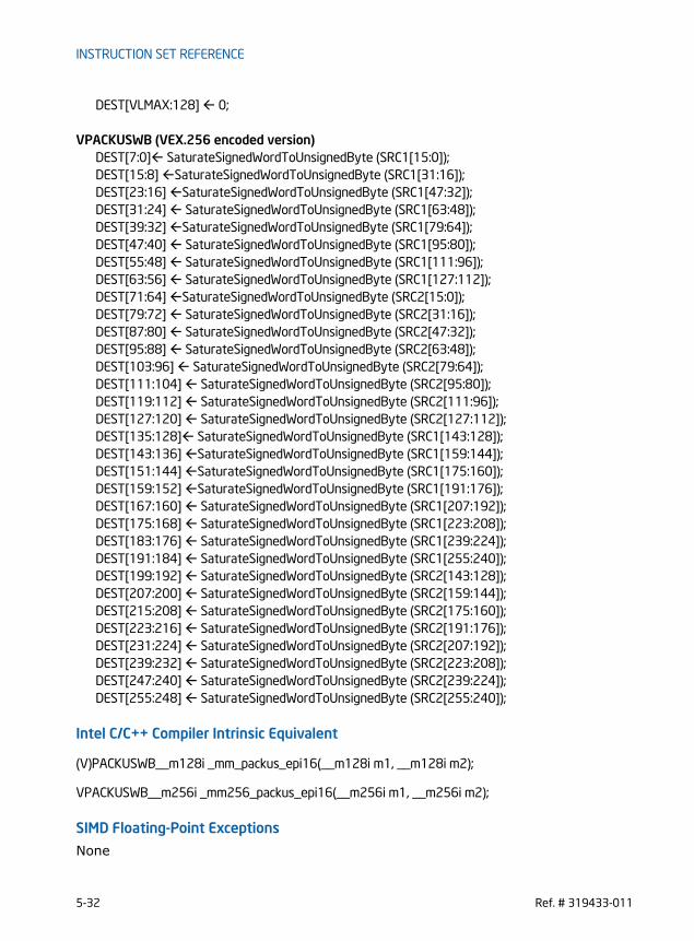
INSTRUCTION SET REFERENCE
DEST[VLMAX:128] 0;
VPACKUSWB (VEX.256 encoded version)DEST[7:0] SaturateSignedWordToUnsignedByte (SRC1[15:0]);DEST[15:8] SaturateSignedWordToUnsignedByte (SRC1[31:16]);DEST[23:16] SaturateSignedWordToUnsignedByte (SRC1[47:32]);DEST[31:24] SaturateSignedWordToUnsignedByte (SRC1[63:48]);DEST[39:32] SaturateSignedWordToUnsignedByte (SRC1[79:64]);DEST[47:40] SaturateSignedWordToUnsignedByte (SRC1[95:80]);DEST[55:48] SaturateSignedWordToUnsignedByte (SRC1[111:96]);DEST[63:56] SaturateSignedWordToUnsignedByte (SRC1[127:112]);DEST[71:64] SaturateSignedWordToUnsignedByte (SRC2[15:0]);DEST[79:72] SaturateSignedWordToUnsignedByte (SRC2[31:16]);DEST[87:80] SaturateSignedWordToUnsignedByte (SRC2[47:32]);DEST[95:88] SaturateSignedWordToUnsignedByte (SRC2[63:48]);DEST[103:96] SaturateSignedWordToUnsignedByte (SRC2[79:64]);DEST[111:104] SaturateSignedWordToUnsignedByte (SRC2[95:80]);DEST[119:112] SaturateSignedWordToUnsignedByte (SRC2[111:96]);DEST[127:120] SaturateSignedWordToUnsignedByte (SRC2[127:112]);DEST[135:128] SaturateSignedWordToUnsignedByte (SRC1[143:128]);DEST[143:136] SaturateSignedWordToUnsignedByte (SRC1[159:144]);DEST[151:144] SaturateSignedWordToUnsignedByte (SRC1[175:160]);DEST[159:152] SaturateSignedWordToUnsignedByte (SRC1[191:176]);DEST[167:160] SaturateSignedWordToUnsignedByte (SRC1[207:192]);DEST[175:168] SaturateSignedWordToUnsignedByte (SRC1[223:208]);DEST[183:176] SaturateSignedWordToUnsignedByte (SRC1[239:224]);DEST[191:184] SaturateSignedWordToUnsignedByte (SRC1[255:240]);DEST[199:192] SaturateSignedWordToUnsignedByte (SRC2[143:128]);DEST[207:200] SaturateSignedWordToUnsignedByte (SRC2[159:144]);DEST[215:208] SaturateSignedWordToUnsignedByte (SRC2[175:160]);DEST[223:216] SaturateSignedWordToUnsignedByte (SRC2[191:176]);DEST[231:224] SaturateSignedWordToUnsignedByte (SRC2[207:192]);DEST[239:232] SaturateSignedWordToUnsignedByte (SRC2[223:208]);DEST[247:240] SaturateSignedWordToUnsignedByte (SRC2[239:224]);DEST[255:248] SaturateSignedWordToUnsignedByte (SRC2[255:240]);
Intel C/C++ Compiler Intrinsic Equivalent
(V)PACKUSWB__m128i _mm_packus_epi16(__m128i m1, __m128i m2);
VPACKUSWB__m256i _mm256_packus_epi16(__m256i m1, __m256i m2);
SIMD Floating-Point Exceptions
None
5-32 Ref. # 319433-011

INSTRUCTION SET REFERENCE
Other Exceptions
See Exceptions Type 4
Ref. # 319433-011 5-33

INSTRUCTION SET REFERENCE
PADDB/PADDW/PADDD/PADDQ — Add Packed IntegersOpcode/Instruction
Op/ En
64/32-bit Mode
CPUID Feature Flag
Description
66 0F FC /r A V/V SSE2 Add packed byte integers from xmm2/m128 and xmm1.PADDB xmm1, xmm2/m128
66 0F FD /r A V/V SSE2 Add packed word integers from xmm2/m128 and xmm1.PADDW xmm1, xmm2/m128
66 0F FE /r A V/V SSE2 Add packed doubleword integers from xmm2/m128 and xmm1.PADDD xmm1, xmm2/m128
66 0F D4/r A V/V SSE2 Add packed quadword integers from xmm2/m128 and xmm1.PADDQ xmm1, xmm2/m128
VEX.NDS.128.66.0F.WIG FC /r B V/V AVX Add packed byte integers from xmm2, and xmm3/m128 and store in xmm1.
VPADDB xmm1, xmm2, xmm3/m128
VEX.NDS.128.66.0F.WIG FD /r B V/V AVX Add packed word integers from xmm2, xmm3/m128 and store in xmm1.
VPADDW xmm1, xmm2, xmm3/m128
VEX.NDS.128.66.0F.WIG FE /r B V/V AVX Add packed doubleword integers from xmm2, xmm3/m128 and store in xmm1.
VPADDD xmm1, xmm2, xmm3/m128
VEX.NDS.128.66.0F.WIG D4 /r B V/V AVX Add packed quadword integers from xmm2, xmm3/m128 and store in xmm1.
VPADDQ xmm1, xmm2, xmm3/m128
VEX.NDS.256.66.0F.WIG FC /r B V/V AVX2 Add packed byte integers from ymm2, and ymm3/m256 and store in xmm1.
VPADDB ymm1, ymm2, ymm3/m256
VEX.NDS.256.66.0F.WIG FD /r B V/V AVX2 Add packed word integers from ymm2, ymm3/m256 and store in ymm1.
VPADDW ymm1, ymm2, ymm3/m256
5-34 Ref. # 319433-011

INSTRUCTION SET REFERENCE
Instruction Operand Encoding
Description
The PADDB and VPADDB instructions add packed byte integers from the first source operand and second source operand and store the packed integer result in destina-tion operand. When an individual result is too large to be represented in 8 bits (over-flow), the result is wrapped around and the low 8 bits are written to the destination operand (that is, the carry is ignored).
The PADDW and VPADDW instructions add packed word integers from the first source operand and second source operand and store the packed integer result in destina-tion operand. When an individual result is too large to be represented in 16 bits (overflow), the result is wrapped around and the low 16 bits are written to the desti-nation operand.
The PADDD and VPADDD instructions add packed doubleword integers from the first source operand and second source operand and store the packed integer result in destination operand. When an individual result is too large to be represented in 32 bits (overflow), the result is wrapped around and the low 32 bits are written to the destination operand.The PADDQ and VPADDQ instructions add packed quadword integers from the first source operand and second source operand and store the packed integer result in destination operand. When a quadword result is too large to be represented in 64 bits (overflow), the result is wrapped around and the low 64 bits are written to the desti-nation element (that is, the carry is ignored).
Note that the (V)PADDB, (V)PADDW, (V)PADDD and (V)PADDQ instructions can operate on either unsigned or signed (two's complement notation) packed integers; however, it does not set bits in the EFLAGS register to indicate overflow and/or a
VEX.NDS.256.66.0F.WIG FE /r B V/V AVX2 Add packed doubleword integers from ymm2, ymm3/m256 and store in ymm1.
VPADDD ymm1, ymm2, ymm3/m256
VEX.NDS.256.66.0F.WIG D4 /r B V/V AVX2 Add packed quadword integers from ymm2, ymm3/m256 and store in ymm1.
VPADDQ ymm1, ymm2, ymm3/m256
Op/En Operand 1 Operand 2 Operand 3 Operand 4
A ModRM:reg (r, w) ModRM:r/m (r) NA NA
B ModRM:reg (w) VEX.vvvv ModRM:r/m (r) NA
Opcode/Instruction
Op/ En
64/32-bit Mode
CPUID Feature Flag
Description
Ref. # 319433-011 5-35

INSTRUCTION SET REFERENCE
carry. To prevent undetected overflow conditions, software must control the ranges of values operated on.VEX.256 encoded version: The first source operand is a YMM register. The second source operand is a YMM register or a 256-bit memory location. The destination operand is a YMM register. VEX.128 encoded version: The first source operand is an XMM register. The second source operand is an XMM register or 128-bit memory location. The destination operand is an XMM register. The upper bits (255:128) of the corresponding YMM register destination are zeroed.128-bit Legacy SSE version: The first source operand is an XMM register. The second operand can be an XMM register or a 128-bit memory location. The destination is not distinct from the first source XMM register and the upper bits (255:128) of the corre-sponding YMM register destination are unmodified.
Operation
PADDB (Legacy SSE instruction)DEST[7:0] DEST[7:0] + SRC[7:0]; (* Repeat add operation for 2nd through 14th byte *)DEST[127:120] DEST[127:120] + SRC[127:120];
PADDW (Legacy SSE instruction)DEST[15:0] DEST[15:0] + SRC[15:0];(* Repeat add operation for 2nd through 7th word *)DEST[127:112] DEST[127:112] + SRC[127:112];
PADDD (Legacy SSE instruction)DEST[31:0] DEST[31:0] + SRC[31:0];(* Repeat add operation for 2nd and 3th doubleword *)DEST[127:96] DEST[127:96] + SRC[127:96];
PADDQ (Legacy SSE instruction)DEST[63:0] DEST[63:0] + SRC[63:0];DEST[127:64] DEST[127:64] + SRC[127:64];
VPADDB (VEX.128 encoded instruction)DEST[7:0] SRC1[7:0] + SRC2[7:0]; (* Repeat add operation for 2nd through 14th byte *)DEST[127:120] SRC1[127:120] + SRC2[127:120];DEST[VLMAX:128] 0;
VPADDW (VEX.128 encoded instruction)DEST[15:0] SRC1[15:0] + SRC2[15:0];(* Repeat add operation for 2nd through 7th word *)
5-36 Ref. # 319433-011
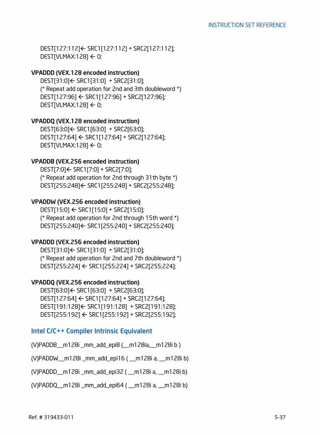
INSTRUCTION SET REFERENCE
DEST[127:112] SRC1[127:112] + SRC2[127:112];DEST[VLMAX:128] 0;
VPADDD (VEX.128 encoded instruction)DEST[31:0] SRC1[31:0] + SRC2[31:0];(* Repeat add operation for 2nd and 3th doubleword *)DEST[127:96] SRC1[127:96] + SRC2[127:96];DEST[VLMAX:128] 0;
VPADDQ (VEX.128 encoded instruction)DEST[63:0] SRC1[63:0] + SRC2[63:0];DEST[127:64] SRC1[127:64] + SRC2[127:64];DEST[VLMAX:128] 0;
VPADDB (VEX.256 encoded instruction)DEST[7:0] SRC1[7:0] + SRC2[7:0]; (* Repeat add operation for 2nd through 31th byte *)DEST[255:248] SRC1[255:248] + SRC2[255:248];
VPADDW (VEX.256 encoded instruction)DEST[15:0] SRC1[15:0] + SRC2[15:0];(* Repeat add operation for 2nd through 15th word *)DEST[255:240] SRC1[255:240] + SRC2[255:240];
VPADDD (VEX.256 encoded instruction)DEST[31:0] SRC1[31:0] + SRC2[31:0];(* Repeat add operation for 2nd and 7th doubleword *)DEST[255:224] SRC1[255:224] + SRC2[255:224];
VPADDQ (VEX.256 encoded instruction)DEST[63:0] SRC1[63:0] + SRC2[63:0];DEST[127:64] SRC1[127:64] + SRC2[127:64];DEST[191:128] SRC1[191:128] + SRC2[191:128];DEST[255:192] SRC1[255:192] + SRC2[255:192];
Intel C/C++ Compiler Intrinsic Equivalent
(V)PADDB__m128i _mm_add_epi8 (__m128ia,__m128i b )
(V)PADDW__m128i _mm_add_epi16 ( __m128i a, __m128i b)
(V)PADDD__m128i _mm_add_epi32 ( __m128i a, __m128i b)
(V)PADDQ__m128i _mm_add_epi64 ( __m128i a, __m128i b)
Ref. # 319433-011 5-37

INSTRUCTION SET REFERENCE
VPADDB__m256i _mm256_add_epi8 (__m256ia,__m256i b )
VPADDW__m256i _mm256_add_epi16 ( __m256i a, __m256i b)
VPADDD__m256i _mm256_add_epi32 ( __m256i a, __m256i b)
VPADDQ__m256i _mm256_add_epi64 ( __m256i a, __m256i b)
SIMD Floating-Point Exceptions
None
Other Exceptions
See Exceptions Type 4
5-38 Ref. # 319433-011

INSTRUCTION SET REFERENCE
PADDSB/PADDSW — Add Packed Signed Integers with Signed Saturation
Instruction Operand Encoding
Description
(V)PADDSB performs a SIMD add of the packed signed integers with saturation from the first source operand and second source operand and stores the packed integer results in the destination operand. When an individual byte result is beyond the
Opcode/Instruction
Op/ En
64/32-bit Mode
CPUID Feature Flag
Description
66 0F EC /r A V/V SSE2 Add packed signed byte integers from xmm2/m128 and xmm1 and saturate the results.
PADDSB xmm1, xmm2/m128
66 0F ED /r A V/V SSE2 Add packed signed word integers from xmm2/m128 and xmm1 and saturate the results.
PADDSW xmm1, xmm2/m128
VEX.NDS.128.66.0F.WIG EC /r B V/V AVX Add packed signed byte integers from xmm2, and xmm3/m128 and store the saturated results in xmm1.
VPADDSB xmm1, xmm2, xmm3/m128
VEX.NDS.128.66.0F.WIG ED /r B V/V AVX Add packed signed word integers from xmm2, and xmm3/m128 and store the saturated results in xmm1.
VPADDSW xmm1, xmm2, xmm3/m128
VEX.NDS.256.66.0F.WIG EC /r B V/V AVX2 Add packed signed byte integers from ymm2, and ymm3/m256 and store the saturated results in ymm1.
VPADDSB ymm1, ymm2, ymm3/m256
VEX.NDS.256.66.0F.WIG ED /r B V/V AVX2 Add packed signed word integers from ymm2, and ymm3/m256 and store the saturated results in ymm1.
VPADDSW ymm1, ymm2, ymm3/m256
Op/En Operand 1 Operand 2 Operand 3 Operand 4
A ModRM:reg (r, w) ModRM:r/m (r) NA NA
B ModRM:reg (w) VEX.vvvv ModRM:r/m (r) NA
Ref. # 319433-011 5-39

INSTRUCTION SET REFERENCE
range of a signed byte integer (that is, greater than 7FH or less than 80H), the satu-rated value of 7FH or 80H, respectively, is written to the destination operand.(V)PADDSW performs a SIMD add of the packed signed word integers with saturation from the first source operand and second source operand and stores the packed integer results in the destination operand. When an individual word result is beyond the range of a signed word integer (that is, greater than 7FFFH or less than 8000H), the saturated value of 7FFFH or 8000H, respectively, is written to the destination operand.VEX.256 encoded version: The first source operand is a YMM register. The second source operand is a YMM register or a 256-bit memory location. The destination operand is a YMM register. VEX.128 encoded version: The first source operand is an XMM register. The second source operand is an XMM register or 128-bit memory location. The destination operand is an XMM register. The upper bits (255:128) of the corresponding YMM register destination are zeroed.128-bit Legacy SSE version: The first source operand is an XMM register. The second operand can be an XMM register or a 128-bit memory location. The destination is not distinct from the first source XMM register and the upper bits (255:128) of the corre-sponding YMM register destination are unmodified.
Operation
PADDSB (Legacy SSE instruction)DEST[7:0] SaturateToSignedByte (DEST[7:0] + SRC[7:0]);(* Repeat add operation for 2nd through 14th bytes *)DEST[127:120] SaturateToSignedByte (DEST[127:120] + SRC[127:120]);
PADDSW (Legacy SSE instruction)DEST[15:0] SaturateToSignedWord (DEST[15:0] + SRC[15:0]);(* Repeat add operation for 2nd through 7th words *)DEST[127:112] SaturateToSignedWord (DEST[127:112] + SRC[127:112])
VPADDSB (VEX.128 encoded version)DEST[7:0] SaturateToSignedByte (SRC1[7:0] + SRC2[7:0]);(* Repeat add operation for 2nd through 14th bytes *)DEST[127:120] SaturateToSignedByte (SRC1[127:120] + SRC2[127:120]);DEST[VLMAX:128] 0
VPADDSW (VEX.128 encoded version)DEST[15:0] SaturateToSignedWord (SRC1[15:0] + SRC2[15:0]);(* Repeat add operation for 2nd through 7th words *)DEST[127:112] SaturateToSignedWord (SRC1[127:112] + SRC2[127:112])DEST[VLMAX:128] 0
5-40 Ref. # 319433-011

INSTRUCTION SET REFERENCE
VPADDSB (VEX.256 encoded version)DEST[7:0] SaturateToSignedByte (SRC1[7:0] + SRC2[7:0]);(* Repeat add operation for 2nd through 31st bytes *)DEST[255:248] SaturateToSignedByte (SRC1[255:248] + SRC2[255:248]);
VPADDSW (VEX.256 encoded version)DEST[15:0] SaturateToSignedWord (SRC1[15:0] + SRC2[15:0]);(* Repeat add operation for 2nd through 15th words *)DEST[255:240] SaturateToSignedWord (SRC1[255:240] + SRC2[255:240])
Intel C/C++ Compiler Intrinsic Equivalent
PADDSB __m128i _mm_adds_epi8 ( __m128i a, __m128i b)
PADDSW __m128i _mm_adds_epi16 ( __m128i a, __m128i b)
VPADDSB __m128i _mm_adds_epi8 ( __m128i a, __m128i b)
VPADDSW __m128i _mm_adds_epi16 ( __m128i a, __m128i b)
VPADDSB __m256i _mm256_adds_epi8 ( __m256i a, __m256i b)
VPADDSW __m256i _mm256_adds_epi16 ( __m256i a, __m256i b)
SIMD Floating-Point Exceptions
None
Ref. # 319433-011 5-41

INSTRUCTION SET REFERENCE
PADDUSB/PADDUSW — Add Packed Unsigned Integers with Unsigned Saturation
Instruction Operand Encoding
Description
(V)PADDUSB performs a SIMD add of the packed unsigned integers with saturation from the first source operand and second source operand and stores the packed integer results in the destination operand. When an individual byte result is beyond
Opcode/Instruction
Op/ En
64/32-bit Mode
CPUID Feature Flag
Description
66 0F DC /r A V/V SSE2 Add packed unsigned byte inte-gers from xmm2/m128 and xmm1 and saturate the results.
PADDUSB xmm1, xmm2/m128
66 0F DD /r A V/V SSE2 Add packed signed word integers from xmm2/m128 and xmm1 and saturate the results.
PADDUSW xmm1, xmm2/m128
VEX.NDS.128.66.0F.WIG DC /r B V/V AVX Add packed unsigned byte inte-gers from xmm2, and xmm3/m128 and store the satu-rated results in xmm1.
VPADDUSB xmm1, xmm2, xmm3/m128
VEX.NDS.128.66.0F.WIG DD /r B V/V AVX Add packed unsigned word inte-gers from xmm2, and xmm3/m128 and store the satu-rated results in xmm1.
VPADDUSW xmm1, xmm2, xmm3/m128
VEX.NDS.256.66.0F.WIG DC /r B V/V AVX2 Add packed unsigned byte inte-gers from ymm2, and ymm3/m256 and store the satu-rated results in ymm1.
VPADDUSB ymm1, ymm2, ymm3/m256
VEX.NDS.256.66.0F.WIG DD /r B V/V AVX2 Add packed unsigned word inte-gers from ymm2, and ymm3/m256 and store the satu-rated results in ymm1.
VPADDUSW ymm1, ymm2, ymm3/m256
Op/En Operand 1 Operand 2 Operand 3 Operand 4
A ModRM:reg (r, w) ModRM:r/m (r) NA NA
B ModRM:reg (w) VEX.vvvv ModRM:r/m (r) NA
5-42 Ref. # 319433-011

INSTRUCTION SET REFERENCE
the range of an unsigned byte integer (that is, greater than FFH), the saturated value of FFH is written to the destination operand.(V)PADDUSW performs a SIMD add of the packed unsigned word integers with satu-ration from the first source operand and second source operand and stores the packed integer results in the destination operand. When an individual word result is beyond the range of an unsigned word integer (that is, greater than FFFFH), the saturated value of FFFFH is written to the destination operand.VEX.256 encoded version: The first source operand is a YMM register. The second source operand is a YMM register or a 256-bit memory location. The destination operand is a YMM register. VEX.128 encoded version: The first source operand is an XMM register. The second source operand is an XMM register or 128-bit memory location. The destination operand is an XMM register. The upper bits (255:128) of the corresponding YMM register destination are zeroed.128-bit Legacy SSE version: The first source operand is an XMM register. The second operand can be an XMM register or a 128-bit memory location. The destination is not distinct from the first source XMM register and the upper bits (255:128) of the corre-sponding YMM register destination are unmodified.
Operation
PADDUSB (Legacy SSE instruction)DEST[7:0] SaturateToUnsignedByte (DEST[7:0] + SRC[7:0]);(* Repeat add operation for 2nd through 14th bytes *)DEST[127:120] SaturateToUnsignedByte (DEST[127:120] + SRC[127:120]);
PADDUSW (Legacy SSE instruction)DEST[15:0] SaturateToUnsignedWord (DEST[15:0] + SRC[15:0]);(* Repeat add operation for 2nd through 7th words *)DEST[127:112] SaturateToUnsignedWord (DEST[127:112] + SRC[127:112])
VPADDUSB (VEX.128 encoded version)DEST[7:0] SaturateToUnsignedByte (SRC1[7:0] + SRC2[7:0]);(* Repeat add operation for 2nd through 14th bytes *)DEST[127:120] SaturateToUnsignedByte (SRC1[127:120] + SRC2[127:120]);DEST[VLMAX:128] 0
VPADDUSW (VEX.128 encoded version)DEST[15:0] SaturateToUnsignedWord (SRC1[15:0] + SRC2[15:0]);(* Repeat add operation for 2nd through 7th words *)DEST[127:112] SaturateToUnsignedWord (SRC1[127:112] + SRC2[127:112])DEST[VLMAX:128] 0
VPADDUSB (VEX.256 encoded version)
Ref. # 319433-011 5-43

INSTRUCTION SET REFERENCE
DEST[7:0] SaturateToUnsignedByte (SRC1[7:0] + SRC2[7:0]);(* Repeat add operation for 2nd through 31st bytes *)DEST[255:248] SaturateToUnsignedByte (SRC1[255:248] + SRC2[255:248]);
VPADDUSW (VEX.256 encoded version)DEST[15:0] SaturateToUnsignedWord (SRC1[15:0] + SRC2[15:0]);(* Repeat add operation for 2nd through 15th words *)DEST[255:240] SaturateToUnsignedWord (SRC1[255:240] + SRC2[255:240])
Intel C/C++ Compiler Intrinsic Equivalent
(V)PADDUSB__m128i _mm_adds_epu8 ( __m128i a, __m128i b)
(V)PADDUSW__m128i _mm_adds_epu16 ( __m128i a, __m128i b)
VPADDUSB__m256i _mm256_adds_epu8 ( __m256i a, __m256i b)
VPADDUSW__m256i _mm256_adds_epu16 ( __m256i a, __m256i b)
SIMD Floating-Point Exceptions
None
Other Exceptions
See Exceptions Type 4
5-44 Ref. # 319433-011

INSTRUCTION SET REFERENCE
PALIGNR - Byte Align
Instruction Operand Encoding
Description
(V)PALIGNR concatenates two blocks of 16-byte data from the first source operand and the second source operand into an intermediate 32-byte composite, shifts the composite at byte granularity to the right by a constant immediate, and extracts the right aligned 16-byte result into the destination. The immediate value is considered unsigned. Immediate shift counts larger than 32 for 128-bit operands produces a zero result. Legacy SSE instructions: In 64-bit mode use the REX prefix to access additional registers.
Opcode/Instruction
Op/ En
64/32-bit Mode
CPUID Feature Flag
Description
66 0F 3A 0F /r ib A V/V SSSE3 Concatenate destination and source operands, extract byte aligned result shifted to the right by constant value in imm8 and result is stored in xmm1.
PALIGNR xmm1, xmm2/m128, imm8
VEX.NDS.128.66.0F3A.WIG 0F /r ib B V/V AVX Concatenate xmm2 and xmm3/m128 into a 32-byte intermediate result, extract byte aligned result shifted to the right by constant value in imm8 and result is stored in xmm1.
VPALIGNR xmm1, xmm2, xmm3/m128, imm8
VEX.NDS.256.66.0F3A.WIG 0F /r ib B V/V AVX2 Concatenate pairs of 16 bytes in ymm2 and ymm3/m256 into 32-byte intermediate result, extract byte-aligned, 16-byte result shifted to the right by constant values in imm8 from each intermediate result, and two 16-byte results are stored in ymm1
VPALIGNR ymm1, ymm2, ymm3/m256, imm8
Op/En Operand 1 Operand 2 Operand 3 Operand 4
A ModRM:reg (r, w) ModRM:r/m (r) NA NA
B ModRM:reg (w) VEX.vvvv ModRM:r/m (r) NA
Ref. # 319433-011 5-45

INSTRUCTION SET REFERENCE
128-bit Legacy SSE version: Bits (255:128) of the corresponding YMM destination register remain unchanged.VEX.256 encoded version: The first source operand is a YMM register and contains two 16-byte blocks. The second source operand is a YMM register or a 256-bit memory location containing two 16-byte block. The destination operand is a YMM register and contain two 16-byte results. The imm8[7:0] is the common shift count used for the two lower 16-byte block sources and the two upper 16-byte block sources. The low 16-byte block of the two source operands produce the low 16-byte result of the destination operand, the high 16-byte block of the two source operands produce the high 16-byte result of the destination operand.VEX.128 encoded version: The first source operand is an XMM register. The second source operand is an XMM register or 128-bit memory location. The destination operand is an XMM register. The upper bits (255:128) of the corresponding YMM register destination are zeroed.Concatenation is done with 128-bit data in the first and second source operand for both 128-bit and 256-bit instructions. The high 128-bits of the intermediate composite 256-bit result came from the 128-bit data from the first source operand; the low 128-bits of the intermediate result came from the 128-bit data of the second source operand.
Figure 5-2. 256-bit VPALIGN Instruction Operation
Operation
PALIGNRtemp1[255:0] ((DEST[127:0] << 128) OR SRC[127:0])>>(imm8*8);DEST[127:0] temp1[127:0]
127 0
SRC1
Imm8[7:0]*8
Imm8[7:0]*8
127 0
SRC2
255 128
SRC1
255 128
SRC2
255 128
DEST
127 0
DEST
5-46 Ref. # 319433-011
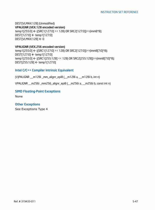
INSTRUCTION SET REFERENCE
DEST[VLMAX:128] (Unmodified)VPALIGNR (VEX.128 encoded version)temp1[255:0] ((SRC1[127:0] << 128) OR SRC2[127:0])>>(imm8*8);DEST[127:0] temp1[127:0]DEST[VLMAX:128] 0
VPALIGNR (VEX.256 encoded version)temp1[255:0] ((SRC1[127:0] << 128) OR SRC2[127:0])>>(imm8[7:0]*8);DEST[127:0] temp1[127:0]temp1[255:0] ((SRC1[255:128] << 128) OR SRC2[255:128])>>(imm8[7:0]*8);DEST[255:128] temp1[127:0]
Intel C/C++ Compiler Intrinsic Equivalent
(V)PALIGNR __m128i _mm_alignr_epi8 (__m128i a, __m128i b, int n)
VPALIGNR __m256i _mm256_alignr_epi8 (__m256i a, __m256i b, const int n)
SIMD Floating-Point Exceptions
None
Other ExceptionsSee Exceptions Type 4
Ref. # 319433-011 5-47

INSTRUCTION SET REFERENCE
PAND — Logical AND
Instruction Operand Encoding
Description
Performs a bitwise logical AND operation on the first source operand and second source operand and stores the result in the destination operand. Each bit of the result is set to 1 if the corresponding bits of the first and second operands are 1, otherwise it is set to 0.VEX.256 encoded version: The first source operand is a YMM register. The second source operand is a YMM register or a 256-bit memory location. The destination operand is a YMM register. VEX.128 encoded version: The first source operand is an XMM register. The second source operand is an XMM register or 128-bit memory location. The destination operand is an XMM register. The upper bits (255:128) of the corresponding YMM register destination are zeroed.128-bit Legacy SSE version: The first source operand is an XMM register. The second operand can be an XMM register or a 128-bit memory location. The destination is not distinct from the first source XMM register and the upper bits (255:128) of the corre-sponding YMM register destination are unmodified.
Operation
PAND (Legacy SSE instruction)DEST[127:0] (DEST[127:0] AND SRC[127:0])
Opcode/Instruction
Op/ En
64/32-bit Mode
CPUID Feature Flag
Description
66 0F DB /r A V/V SSE2 Bitwise AND of xmm2/m128 and xmm1.PAND xmm1, xmm2/.m128
VEX.NDS.128.66.0F.WIG DB /r B V/V AVX Bitwise AND of xmm2, and xmm3/m128 and store result in xmm1.
VPAND xmm1, xmm2, xmm3/.m128
VEX.NDS.256.66.0F.WIG DB /r B V/V AVX2 Bitwise AND of ymm2, and ymm3/m256 and store result in ymm1.
VPAND ymm1, ymm2, ymm3/.m256
Op/En Operand 1 Operand 2 Operand 3 Operand 4
A ModRM:reg (r, w) ModRM:r/m (r) NA NA
B ModRM:reg (w) VEX.vvvv ModRM:r/m (r) NA
5-48 Ref. # 319433-011

INSTRUCTION SET REFERENCE
VPAND (VEX.128 encoded instruction)DEST[127:0] (SRC1[127:0] AND SRC2[127:0])DEST[VLMAX:128] 0
VPAND (VEX.256 encoded instruction)DEST[255:0] (SRC1[255:0] AND SRC2[255:0])
Intel C/C++ Compiler Intrinsic Equivalent
(V)PAND__m128i _mm_and_si128 ( __m128i a, __m128i b)
VPAND__m256i _mm256_and_si256 ( __m256i a, __m256i b)
SIMD Floating-Point Exceptions
None
Other Exceptions
See Exceptions Type 4
Ref. # 319433-011 5-49

INSTRUCTION SET REFERENCE
PANDN — Logical AND NOT
Instruction Operand Encoding
Description
Performs a bitwise logical NOT operation on the first source operand, then performs bitwise AND with second source operand and stores the result in the destination operand. Each bit of the result is set to 1 if the corresponding bit in the first operand is 0 and the corresponding bit in the second operand is 1, otherwise it is set to 0.VEX.256 encoded version: The first source operand is a YMM register. The second source operand is a YMM register or a 256-bit memory location. The destination operand is a YMM register. VEX.128 encoded version: The first source operand is an XMM register. The second source operand is an XMM register or 128-bit memory location. The destination operand is an XMM register. The upper bits (255:128) of the corresponding YMM register destination are zeroed.128-bit Legacy SSE version: The first source operand is an XMM register. The second operand can be an XMM register or a 128-bit memory location. The destination is not distinct from the first source XMM register and the upper bits (255:128) of the corre-sponding YMM register destination are unmodified.
Operation
PANDN (Legacy SSE instruction)DEST[127:0] ((NOT DEST[127:0]) AND SRC[127:0])
Opcode/Instruction
Op/ En
64/32-bit Mode
CPUID Feature Flag
Description
66 0F DF /r A V/V SSE2 Bitwise AND NOT of xmm2/m128 and xmm1.PANDN xmm1, xmm2/.m128
VEX.NDS.128.66.0F.WIG DF /r B V/V AVX Bitwise AND NOT of xmm2, and xmm3/m128 and store result in xmm1.
VPANDN xmm1, xmm2, xmm3/.m128
VEX.NDS.256.66.0F.WIG DF /r B V/V AVX2 Bitwise AND NOT of ymm2, and ymm3/m256 and store result in ymm1.
VPANDN ymm1, ymm2, ymm3/.m256
Op/En Operand 1 Operand 2 Operand 3 Operand 4
A ModRM:reg (r, w) ModRM:r/m (r) NA NA
B ModRM:reg (w) VEX.vvvv ModRM:r/m (r) NA
5-50 Ref. # 319433-011

INSTRUCTION SET REFERENCE
VPANDN (VEX.128 encoded instruction)DEST[127:0] (( NOT SRC1[127:0]) AND SRC2[127:0])DEST[VLMAX:128] 0
VPANDN (VEX.256 encoded instruction)DEST[255:0] ((NOT SRC1[255:0]) AND SRC2[255:0])
Intel C/C++ Compiler Intrinsic Equivalent
(V)PANDN__m128i _mm_andnot_si128 ( __m128i a, __m128i b)
VPANDN__m256i _mm256_andnot_si256 ( __m256i a, __m256i b)
SIMD Floating-Point Exceptions
None
Other Exceptions
See Exceptions Type 4
Ref. # 319433-011 5-51

INSTRUCTION SET REFERENCE
PAVGB/PAVGW — Average Packed Integers
Instruction Operand Encoding
Description
Performs a SIMD average of the packed unsigned integers from the second source operand and the first operand, and stores the results in the destination operand. For each corresponding pair of data elements in the first and second operands, the
Opcode/Instruction
Op/ En
64/32-bit Mode
CPUID Feature Flag
Description
66 0F E0, /r A V/V SSE2 Average packed unsigned byte integers from xmm2/m128 and xmm1 with rounding.
PAVGB xmm1, xmm2/m128
66 0F E3, /r A V/V SSE2 Average packed unsigned word integers from xmm2/m128 and xmm1 with rounding.
PAVGW xmm1, xmm2/m128
VEX.NDS.128.66.0F.WIG E0 /r B V/V AVX Average packed unsigned byte integers from xmm2, and xmm3/m128 with rounding and store to xmm1.
VPAVGB xmm1, xmm2, xmm3/m128
VEX.NDS.128.66.0F.WIG E3 /r B V/V AVX Average packed unsigned word integers from xmm2, xmm3/m128 with rounding to xmm1.
VPAVGW xmm1, xmm2, xmm3/m128
VEX.NDS.256.66.0F.WIG E0 /r B V/V AVX2 Average packed unsigned byte integers from ymm2, and ymm3/m256 with rounding and store to ymm1.
VPAVGB ymm1, ymm2, ymm3/m256
VEX.NDS.256.66.0F.WIG E3 /r B V/V AVX2 Average packed unsigned word integers from ymm2, ymm3/m256 with rounding to ymm1.
VPAVGW ymm1, ymm2, ymm3/m256
Op/En Operand 1 Operand 2 Operand 3 Operand 4
A ModRM:reg (r, w) ModRM:r/m (r) NA NA
B ModRM:reg (w) VEX.vvvv ModRM:r/m (r) NA
5-52 Ref. # 319433-011

INSTRUCTION SET REFERENCE
elements are added together, a 1 is added to the temporary sum, and that result is shifted right one bit position.
The (V)PAVGB instruction operates on packed unsigned bytes and the (V)PAVGW instruction operates on packed unsigned words.VEX.256 encoded version: The first source operand is a YMM register. The second source operand is a YMM register or a 256-bit memory location. The destination operand is a YMM register. VEX.128 encoded version: The first source operand is an XMM register. The second source operand is an XMM register or 128-bit memory location. The destination operand is an XMM register. The upper bits (255:128) of the corresponding YMM register destination are zeroed.128-bit Legacy SSE version: The first source operand is an XMM register. The second operand can be an XMM register or a 128-bit memory location. The destination is not distinct from the first source XMM register and the upper bits (255:128) of the corre-sponding YMM register destination are unmodified.
Operation
PAVGB (Legacy SSE instruction)DEST[7:0] (SRC[7:0] + DEST[7:0] + 1) >> 1; (* Temp sum before shifting is 9 bits *)(* Repeat operation performed for bytes 2 through 15 )SRC[63:56] (SRC[127:120] + DEST[127:120)] + 1) >> 1;
PAVGW (Legacy SSE instruction)SRC[15:0] (SRC[15:0] + DEST[15:0] + 1) >> 1; (* Temp sum before shifting is 17 bits *)(* Repeat operation performed for words 2 through 7)DEST[127:48] (SRC[127:112] + DEST[127:112] + 1) >> 1;
VPAVGB (VEX.128 encoded instruction)DEST[7:0] (SRC1[7:0] + SRC2[7:0] + 1) >> 1; (* Temp sum before shifting is 9 bits *)(* Repeat operation performed for bytes 2 through 15)DEST[127:48] (SRC1[127:112] + SRC2[127:112] + 1) >> 1;DEST[VLMAX:128] 0
VPAVGW (VEX.128 encoded instruction)DEST[15:0] (SRC1[15:0] + SRC2[15:0] + 1) >> 1; (* Temp sum before shifting is 17 bits *)(* Repeat operation performed for words 2 through 7)DEST[127:4] (SRC1[127:112] + SRC2[127:112] + 1) >> 1;DEST[VLMAX:128] 0
VPAVGB (VEX.256 encoded instruction)DEST[7:0] (SRC1[7:0] + SRC2[7:0] + 1) >> 1; (* Temp sum before shifting is 9 bits *)(* Repeat operation performed for bytes 2 through 31)
Ref. # 319433-011 5-53

INSTRUCTION SET REFERENCE
DEST[255:248] (SRC1[255:248] + SRC2[255:248] + 1) >> 1;
VPAVGW (VEX.256 encoded instruction)DEST[15:0] (SRC1[15:0] + SRC2[15:0] + 1) >> 1; (* Temp sum before shifting is 17 bits *)(* Repeat operation performed for words 2 through 15)DEST[255:14]) (SRC1[255:240] + SRC2[255:240] + 1) >> 1;
Intel C/C++ Compiler Intrinsic Equivalent
(V)PAVGB__m128i _mm_avg_epu8 ( __m128i a, __m128i b)
(V)PAVGW__m128i _mm_avg_epu16 ( __m128i a, __m128i b)
VPAVGB__m256i _mm256_avg_epu8 ( __m256i a, __m256i b)
VPAVGW__m256i _mm256_avg_epu16 ( __m256i a, __m256i b)
SIMD Floating-Point Exceptions
None
Other Exceptions
See Exceptions Type 4
5-54 Ref. # 319433-011

INSTRUCTION SET REFERENCE
PBLENDVB — Variable Blend Packed Bytes
Instruction Operand Encoding
Description
Conditionally copy byte elements from the second source operand and the first source operand depending on mask bits defined in the mask register operand. The mask bits are the most significant bit in each byte element of the mask register.Each byte element of the destination operand is copied from the corresponding byte element in the second source operand if a mask bit is "1", or the corresponding byte element in the first source operand if a mask bit is "0".The register assignment of the implicit third operand is defined to be the architectural register XMM0.128-bit Legacy SSE version: The first source operand and the destination operand is the same. Bits (255:128) of the corresponding YMM destination register remain
Opcode/Instruction
Op/ En
64/32-bit Mode
CPUID Feature Flag
Description
66 0F 38 10 /r A V/V SSE4_1 Select byte values from xmm1 and xmm2/m128 from mask specified in the high bit of each byte in XMM0 and store the values into xmm1.
PBLENDVB xmm1, xmm2/m128, <XMM0>
VEX.NDS.128.66.0F3A.W0 4C /r /is4 B V/V AVX Select byte values from xmm2 and xmm3/m128 from mask specified in the high bit of each byte in xmm4 and store the values into xmm1.
VPBLENDVB xmm1, xmm2, xmm3/m128, xmm4
VEX.NDS.256.66.0F3A.W0 4C /r /is4 B V/V AVX2 Select byte values from ymm2 and ymm3/m256 from mask specified in the high bit of each byte in ymm4 and store the values into ymm1.
VPBLENDVB ymm1, ymm2, ymm3/m256, ymm4
Op/En Operand 1 Operand 2 Operand 3 Operand 4
A ModRM:reg (r, w) ModRM:r/m (r) NA NA
B ModRM:reg (w) VEX.vvvv ModRM:r/m (r) imm[3:0](r)
Ref. # 319433-011 5-55

INSTRUCTION SET REFERENCE
unchanged. The mask register operand is implicitly defined to be the architectural register XMM0. An attempt to execute PBLENDVB with a VEX prefix will cause #UD.VEX.128 encoded version: The first source operand and the destination operand are XMM registers. The second source operand is an XMM register or 128-bit memory location. The mask operand is the third source register, and encoded in bits[7:4] of the immediate byte(imm8). The bits[3:0] of imm8 are ignored. In 32-bit mode, imm8[7] is ignored. The upper bits (255:128) of the corresponding YMM register (destination register) are zeroed. VEX.256 encoded version: The first source operand and the destination operand are YMM registers. The second source operand is an YMM register or 256-bit memory location. The third source register is an YMM register and encoded in bits[7:4] of the immediate byte(imm8). The bits[3:0] of imm8 are ignored. In 32-bit mode, imm8[7] is ignored. VPBLENDVB permits the mask to be any XMM or YMM register. In contrast, PBLENDVB treats XMM0 implicitly as the mask and do not support non-destructive destination operation. An attempt to execute PBLENDVB encoded with a VEX prefix will cause a #UD exception.
Operation
VPBLENDVB (VEX.256 encoded version)MASK SRC3IF (MASK[7] == 1) THEN DEST[7:0] ? SRC2[7:0];ELSE DEST[7:0] SRC1[7:0];IF (MASK[15] == 1) THEN DEST[15:8] ? SRC2[15:8];ELSE DEST[15:8] SRC1[15:8];IF (MASK[23] == 1) THEN DEST[23:16] ? SRC2[23:16]ELSE DEST[23:16] SRC1[23:16];IF (MASK[31] == 1) THEN DEST[31:24] ? SRC2[31:24]ELSE DEST[31:24] SRC1[31:24];IF (MASK[39] == 1) THEN DEST[39:32] ? SRC2[39:32]ELSE DEST[39:32] SRC1[39:32];IF (MASK[47] == 1) THEN DEST[47:40] ? SRC2[47:40]ELSE DEST[47:40] SRC1[47:40];IF (MASK[55] == 1) THEN DEST[55:48] ? SRC2[55:48]ELSE DEST[55:48] SRC1[55:48];IF (MASK[63] == 1) THEN DEST[63:56] ? SRC2[63:56]ELSE DEST[63:56] SRC1[63:56];IF (MASK[71] == 1) THEN DEST[71:64] ? SRC2[71:64]ELSE DEST[71:64] SRC1[71:64];IF (MASK[79] == 1) THEN DEST[79:72] ? SRC2[79:72]ELSE DEST[79:72] SRC1[79:72];IF (MASK[87] == 1) THEN DEST[87:80] ? SRC2[87:80]ELSE DEST[87:80] SRC1[87:80];
5-56 Ref. # 319433-011

INSTRUCTION SET REFERENCE
IF (MASK[95] == 1) THEN DEST[95:88] SRC2[95:88]ELSE DEST[95:88] SRC1[95:88];IF (MASK[103] == 1) THEN DEST[103:96] SRC2[103:96]ELSE DEST[103:96] SRC1[103:96];IF (MASK[111] == 1) THEN DEST[111:104] SRC2[111:104]ELSE DEST[111:104] SRC1[111:104];IF (MASK[119] == 1) THEN DEST[119:112] SRC2[119:112]ELSE DEST[119:112] SRC1[119:112];IF (MASK[127] == 1) THEN DEST[127:120] SRC2[127:120]ELSE DEST[127:120] SRC1[127:120])IF (MASK[135] == 1) THEN DEST[135:128] SRC2[135:128];ELSE DEST[135:128] SRC1[135:128];IF (MASK[143] == 1) THEN DEST[143:136] SRC2[143:136];ELSE DEST[[143:136] SRC1[143:136];IF (MASK[151] == 1) THEN DEST[151:144] SRC2[151:144]ELSE DEST[151:144] SRC1[151:144];IF (MASK[159] == 1) THEN DEST[159:152] SRC2[159:152]ELSE DEST[159:152] SRC1[159:152];IF (MASK[167] == 1) THEN DEST[167:160] SRC2[167:160]ELSE DEST[167:160] SRC1[167:160];IF (MASK[175] == 1) THEN DEST[175:168] SRC2[175:168]ELSE DEST[175:168] SRC1[175:168];IF (MASK[183] == 1) THEN DEST[183:176] SRC2[183:176]ELSE DEST[183:176] SRC1[183:176];IF (MASK[191] == 1) THEN DEST[191:184] SRC2[191:184]ELSE DEST[191:184] SRC1[191:184];IF (MASK[199] == 1) THEN DEST[199:192] SRC2[199:192]ELSE DEST[199:192] SRC1[199:192];IF (MASK[207] == 1) THEN DEST[207:200] SRC2[207:200]ELSE DEST[207:200] SRC1[207:200]IF (MASK[215] == 1) THEN DEST[215:208] SRC2[215:208]ELSE DEST[215:208] SRC1[215:208];IF (MASK[223] == 1) THEN DEST[223:216] SRC2[223:216]ELSE DEST[223:216] SRC1[223:216];IF (MASK[231] == 1) THEN DEST[231:224] SRC2[231:224]ELSE DEST[231:224] SRC1[231:224];IF (MASK[239] == 1) THEN DEST[239:232] SRC2[239:232]ELSE DEST[239:232] SRC1[239:232];IF (MASK[247] == 1) THEN DEST[247:240] SRC2[247:240]ELSE DEST[247:240] SRC1[247:240];IF (MASK[255] == 1) THEN DEST[255:248] SRC2[255:248]ELSE DEST[255:248] SRC1[255:248]
Ref. # 319433-011 5-57

INSTRUCTION SET REFERENCE
VPBLENDVB (VEX.128 encoded version)MASK XMM0IF (MASK[7] == 1) THEN DEST[7:0] SRC2[7:0];ELSE DEST[7:0] SRC1[7:0];IF (MASK[15] == 1) THEN DEST[15:8] SRC2[15:8];ELSE DEST[15:8] SRC1[15:8];IF (MASK[23] == 1) THEN DEST[23:16] SRC2[23:16]ELSE DEST[23:16] SRC1[23:16];IF (MASK[31] == 1) THEN DEST[31:24] SRC2[31:24]ELSE DEST[31:24] SRC1[31:24];IF (MASK[39] == 1) THEN DEST[39:32] SRC2[39:32]ELSE DEST[39:32] SRC1[39:32];IF (MASK[47] == 1) THEN DEST[47:40] SRC2[47:40]ELSE DEST[47:40] SRC1[47:40];IF (MASK[55] == 1) THEN DEST[55:48] SRC2[55:48]ELSE DEST[55:48] SRC1[55:48];IF (MASK[63] == 1) THEN DEST[63:56] SRC2[63:56]ELSE DEST[63:56] SRC1[63:56];IF (MASK[71] == 1) THEN DEST[71:64] SRC2[71:64]ELSE DEST[71:64] SRC1[71:64];IF (MASK[79] == 1) THEN DEST[79:72] SRC2[79:72]ELSE DEST[79:72] SRC1[79:72];IF (MASK[87] == 1) THEN DEST[87:80] SRC2[87:80]ELSE DEST[87:80] SRC1[87:80];IF (MASK[95] == 1) THEN DEST[95:88] SRC2[95:88]ELSE DEST[95:88] SRC1[95:88];IF (MASK[103] == 1) THEN DEST[103:96] SRC2[103:96]ELSE DEST[103:96] SRC1[103:96];IF (MASK[111] == 1) THEN DEST[111:104] SRC2[111:104]ELSE DEST[111:104] SRC1[111:104];IF (MASK[119] == 1) THEN DEST[119:112] SRC2[119:112]ELSE DEST[119:112] SRC1[119:112];IF (MASK[127] == 1) THEN DEST[127:120] SRC2[127:120]ELSE DEST[127:120] SRC1[127:120])DEST[VLMAX:128] 0
PBLENDVB (128-bit Legacy SSE version)MASK XMM0IF (MASK[7] == 1) THEN DEST[7:0] SRC[7:0];ELSE DEST[7:0] DEST[7:0];IF (MASK[15] == 1) THEN DEST[15:8] SRC[15:8];ELSE DEST[15:8] DEST[15:8];IF (MASK[23] == 1) THEN DEST[23:16] SRC[23:16]
5-58 Ref. # 319433-011

INSTRUCTION SET REFERENCE
ELSE DEST[23:16] DEST[23:16];IF (MASK[31] == 1) THEN DEST[31:24] SRC[31:24]ELSE DEST[31:24] DEST[31:24];IF (MASK[39] == 1) THEN DEST[39:32] SRC[39:32]ELSE DEST[39:32] DEST[39:32];IF (MASK[47] == 1) THEN DEST[47:40] SRC[47:40]ELSE DEST[47:40] DEST[47:40];IF (MASK[55] == 1) THEN DEST[55:48] SRC[55:48]ELSE DEST[55:48] DEST[55:48];IF (MASK[63] == 1) THEN DEST[63:56] SRC[63:56]ELSE DEST[63:56] DEST[63:56];IF (MASK[71] == 1) THEN DEST[71:64] SRC[71:64]ELSE DEST[71:64] DEST[71:64];IF (MASK[79] == 1) THEN DEST[79:72] SRC[79:72]ELSE DEST[79:72] DEST[79:72];IF (MASK[87] == 1) THEN DEST[87:80] SRC[87:80]ELSE DEST[87:80] DEST[87:80];IF (MASK[95] == 1) THEN DEST[95:88] SRC[95:88]ELSE DEST[95:88] DEST[95:88];IF (MASK[103] == 1) THEN DEST[103:96] SRC[103:96]ELSE DEST[103:96] DEST[103:96];IF (MASK[111] == 1) THEN DEST[111:104] SRC[111:104]ELSE DEST[111:104] DEST[111:104];IF (MASK[119] == 1) THEN DEST[119:112] SRC[119:112]ELSE DEST[119:112] DEST[119:112];IF (MASK[127] == 1) THEN DEST[127:120] SRC[127:120]ELSE DEST[127:120] DEST[127:120])
DEST[VLMAX:128] (Unmodified)
Intel C/C++ Compiler Intrinsic Equivalent
(V) PBLENDVB __m128i _mm_blendv_epi8 (__m128i v1, __m128i v2, __m128i mask);
VPBLENDVB __m256i _mm256_blendv_epi8 (__m256i v1, __m256i v2, __m256i mask);
SIMD Floating-Point Exceptions
None
Other ExceptionsSee Exceptions Type 4; additionally,#UD If VEX.W = 1.
Ref. # 319433-011 5-59
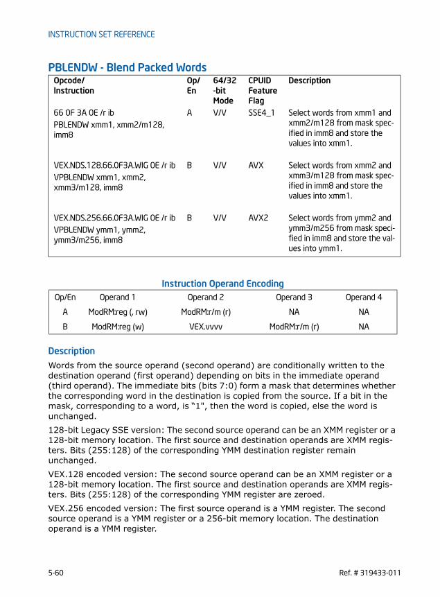
INSTRUCTION SET REFERENCE
PBLENDW - Blend Packed Words
Instruction Operand Encoding
Description
Words from the source operand (second operand) are conditionally written to the destination operand (first operand) depending on bits in the immediate operand (third operand). The immediate bits (bits 7:0) form a mask that determines whether the corresponding word in the destination is copied from the source. If a bit in the mask, corresponding to a word, is “1", then the word is copied, else the word is unchanged.128-bit Legacy SSE version: The second source operand can be an XMM register or a 128-bit memory location. The first source and destination operands are XMM regis-ters. Bits (255:128) of the corresponding YMM destination register remain unchanged.VEX.128 encoded version: The second source operand can be an XMM register or a 128-bit memory location. The first source and destination operands are XMM regis-ters. Bits (255:128) of the corresponding YMM register are zeroed.VEX.256 encoded version: The first source operand is a YMM register. The second source operand is a YMM register or a 256-bit memory location. The destination operand is a YMM register.
Opcode/Instruction
Op/ En
64/32-bit Mode
CPUID Feature Flag
Description
66 0F 3A 0E /r ib A V/V SSE4_1 Select words from xmm1 and xmm2/m128 from mask spec-ified in imm8 and store the values into xmm1.
PBLENDW xmm1, xmm2/m128, imm8
VEX.NDS.128.66.0F3A.WIG 0E /r ib B V/V AVX Select words from xmm2 and xmm3/m128 from mask spec-ified in imm8 and store the values into xmm1.
VPBLENDW xmm1, xmm2, xmm3/m128, imm8
VEX.NDS.256.66.0F3A.WIG 0E /r ib B V/V AVX2 Select words from ymm2 and ymm3/m256 from mask speci-fied in imm8 and store the val-ues into ymm1.
VPBLENDW ymm1, ymm2, ymm3/m256, imm8
Op/En Operand 1 Operand 2 Operand 3 Operand 4
A ModRM:reg (, rw) ModRM:r/m (r) NA NA
B ModRM:reg (w) VEX.vvvv ModRM:r/m (r) NA
5-60 Ref. # 319433-011

INSTRUCTION SET REFERENCE
Operation
VPBLENDW (VEX.256 encoded version)IF (imm8[0] == 1) THEN DEST[15:0] SRC2[15:0]ELSE DEST[15:0] SRC1[15:0]IF (imm8[1] == 1) THEN DEST[31:16] SRC2[31:16]ELSE DEST[31:16] SRC1[31:16]IF (imm8[2] == 1) THEN DEST[47:32] SRC2[47:32]ELSE DEST[47:32] SRC1[47:32]IF (imm8[3] == 1) THEN DEST[63:48] SRC2[63:48]ELSE DEST[63:48] SRC1[63:48]IF (imm8[4] == 1) THEN DEST[79:64] SRC2[79:64]ELSE DEST[79:64] SRC1[79:64]IF (imm8[5] == 1) THEN DEST[95:80] SRC2[95:80]ELSE DEST[95:80] SRC1[95:80]IF (imm8[6] == 1) THEN DEST[111:96] SRC2[111:96]ELSE DEST[111:96] SRC1[111:96]IF (imm8[7] == 1) THEN DEST[127:112] SRC2[127:112]ELSE DEST[127:112] SRC1[127:112]IF (imm8[0] == 1) THEN DEST[143:128] SRC2[143:128]ELSE DEST[143:128] SRC1[143:128]IF (imm8[1] == 1) THEN DEST[159:144] SRC2[159:144]ELSE DEST[159:144] SRC1[159:144]IF (imm8[2] == 1) THEN DEST[175:160] SRC2[175:160]ELSE DEST[175:160] SRC1[175:160]IF (imm8[3] == 1) THEN DEST[191:176] SRC2[191:176]ELSE DEST[191:176] SRC1[191:176]IF (imm8[4] == 1) THEN DEST[207:192] SRC2[207:192]ELSE DEST[207:192] SRC1[207:192]IF (imm8[5] == 1) THEN DEST[223:208] SRC2[223:208]ELSE DEST[223:208] SRC1[223:208]IF (imm8[6] == 1) THEN DEST[239:224] SRC2[239:224]ELSE DEST[239:224] SRC1[239:224]IF (imm8[7] == 1) THEN DEST[255:240] SRC2[255:240]ELSE DEST[255:240] SRC1[255:240]
VPBLENDW (VEX.128 encoded version)IF (imm8[0] == 1) THEN DEST[15:0] SRC2[15:0]ELSE DEST[15:0] SRC1[15:0]IF (imm8[1] == 1) THEN DEST[31:16] SRC2[31:16]ELSE DEST[31:16] SRC1[31:16]IF (imm8[2] == 1) THEN DEST[47:32] SRC2[47:32]ELSE DEST[47:32] SRC1[47:32]IF (imm8[3] == 1) THEN DEST[63:48] SRC2[63:48]
Ref. # 319433-011 5-61

INSTRUCTION SET REFERENCE
ELSE DEST[63:48] SRC1[63:48]IF (imm8[4] == 1) THEN DEST[79:64] SRC2[79:64]ELSE DEST[79:64] SRC1[79:64]IF (imm8[5] == 1) THEN DEST[95:80] SRC2[95:80]ELSE DEST[95:80] SRC1[95:80]IF (imm8[6] == 1) THEN DEST[111:96] SRC2[111:96]ELSE DEST[111:96] SRC1[111:96]IF (imm8[7] == 1) THEN DEST[127:112] SRC2[127:112]ELSE DEST[127:112] SRC1[127:112]DEST[VLMAX:128] 0
PBLENDW (128-bit Legacy SSE version)IF (imm8[0] == 1) THEN DEST[15:0] SRC[15:0]ELSE DEST[15:0] DEST[15:0]IF (imm8[1] == 1) THEN DEST[31:16] SRC[31:16]ELSE DEST[31:16] DEST[31:16]IF (imm8[2] == 1) THEN DEST[47:32] SRC[47:32]ELSE DEST[47:32] DEST[47:32]IF (imm8[3] == 1) THEN DEST[63:48] SRC[63:48]ELSE DEST[63:48] DEST[63:48]IF (imm8[4] == 1) THEN DEST[79:64] SRC[79:64]ELSE DEST[79:64] DEST[79:64]IF (imm8[5] == 1) THEN DEST[95:80] SRC[95:80]ELSE DEST[95:80] DEST[95:80]IF (imm8[6] == 1) THEN DEST[111:96] SRC[111:96]ELSE DEST[111:96] DEST[111:96]IF (imm8[7] == 1) THEN DEST[127:112] SRC[127:112]ELSE DEST[127:112] DEST[127:112]
DEST[VLMAX:128] (Unmodified)
Intel C/C++ Compiler Intrinsic Equivalent
(V)PBLENDW __m128i _mm_blend_epi16 (__m128i v1, __m128i v2, const int mask)
VPBLENDW __m256i _mm256_blend_epi16 (__m256i v1, __m256i v2, const int mask)
SIMD Floating-Point Exceptions
None
Other ExceptionsSee Exceptions Type 4
5-62 Ref. # 319433-011

INSTRUCTION SET REFERENCE
PCMPEQB/PCMPEQW/PCMPEQD/PCMPEQQ- Compare Packed Integers for Equality
Opcode/Instruction
Op/ En
64/32-bit Mode
CPUID Feature Flag
Description
66 0F 74 /r A V/V SSE2 Compare packed bytes in xmm2/m128 and xmm1 for equality.
PCMPEQB xmm1, xmm2/m128
66 0F 75 /r A V/V SSE2 Compare packed words in xmm2/m128 and xmm1 for equality.
PCMPEQW xmm1, xmm2/m128
66 0F 76 /r A V/V SSE2 Compare packed doublewords in xmm2/m128 and xmm1 for equality.
PCMPEQD xmm1, xmm2/m128
66 0F 38 29 /r A V/V SSE4_1 Compare packed quadwords in xmm2/m128 and xmm1 for equality.
PCMPEQQ xmm1, xmm2/m128
VEX.NDS.128.66.0F.WIG 74 /r B V/V AVX Compare packed bytes in xmm3/m128 and xmm2 for equality.
VPCMPEQB xmm1, xmm2, xmm3 /m128
VEX.NDS.128.66.0F.WIG 75 /r B V/V AVX Compare packed words in xmm3/m128 and xmm2 for equality.
VPCMPEQW xmm1, xmm2, xmm3/m128
VEX.NDS.128.66.0F.WIG 76 /r B V/V AVX Compare packed doublewords in xmm3/m128 and xmm2 for equality.
VPCMPEQD xmm1, xmm2, xmm3/m128
VEX.NDS.128.66.0F38.WIG 29 /r B V/V AVX Compare packed quadwords in xmm3/m128 and xmm2 for equality.
VPCMPEQQ xmm1, xmm2, xmm3/m128
VEX.NDS.256.66.0F.WIG 74 /r B V/V AVX2 Compare packed bytes in ymm3/m256 and ymm2 for equality.
VPCMPEQB ymm1, ymm2, ymm3 /m256
VEX.NDS.256.66.0F.WIG 75 /r B V/V AVX2 Compare packed words in ymm3/m256 and ymm2 for equality.
VPCMPEQW ymm1, ymm2, ymm3 /m256
Ref. # 319433-011 5-63

INSTRUCTION SET REFERENCE
Instruction Operand Encoding
Description
Performs a SIMD compare for equality of the packed bytes, words, doublewords, or quadwords in the first source operand and the second source operand. If a pair of data elements is equal the corresponding data element in the destination operand is set to all 1s, otherwise it is set to all 0s. The (V)PCMPEQB instruction compares the corresponding bytes in the destination and source operands; the (V)PCMPEQW instruction compares the corresponding words in the destination and source operands; the (V)PCMPEQD instruction compares the corresponding doublewords in the destination and source operands, and the (V)PCMPEQQ instruction compares the corresponding quadwords in the destination and source operands.Legacy SSE instructions: The second source operand can be an XMM register or a 128-bit memory location. The first source and destination operands are XMM regis-ters. In 64-bit mode using a REX prefix in the form of REX.R permits this instruction to access additional registers (XMM8-XMM15).128-bit Legacy SSE version: The second source operand can be an XMM register or a 128-bit memory location. The first source and destination operands are XMM regis-ters. Bits (255:128) of the corresponding YMM destination register remain unchanged.VEX.128 encoded version: The second source operand can be an XMM register or a 128-bit memory location. The first source and destination operands are XMM regis-ters. Bits (255:128) of the corresponding YMM register are zeroed.VEX.256 encoded version: The first source operand is a YMM register. The second source operand is a YMM register or a 256-bit memory location. The destination operand is a YMM register.
VEX.NDS.256.66.0F.WIG 76 /r B V/V AVX2 Compare packed doublewords in ymm3/m256 and ymm2 for equality.
VPCMPEQD ymm1, ymm2, ymm3 /m256
VEX.NDS.256.66.0F38.WIG 29 /r B V/V AVX2 Compare packed quadwords in ymm3/m256 and ymm2 for equality.
VPCMPEQQ ymm1, ymm2, ymm3 /m256
Op/En Operand 1 Operand 2 Operand 3 Operand 4
A ModRM:reg (r, w) ModRM:r/m (r) NA NA
B ModRM:reg (w) VEX.vvvv ModRM:r/m (r) NA
Opcode/Instruction
Op/ En
64/32-bit Mode
CPUID Feature Flag
Description
5-64 Ref. # 319433-011

INSTRUCTION SET REFERENCE
Operation
COMPARE_BYTES_EQUAL (SRC1, SRC2)IF SRC1[7:0] = SRC2[7:0]THEN DEST[7:0] FFH;ELSE DEST[7:0] 0; FI;
(* Continue comparison of 2nd through 15th bytes in SRC1 and SRC2 *)IF SRC1[127:120] = SRC2[127:120]THEN DEST[127:120] FFH;ELSE DEST[127:120] 0; FI;
COMPARE_WORDS_EQUAL (SRC1, SRC2)IF SRC1[15:0] = SRC2[15:0]THEN DEST[15:0] FFFFH;ELSE DEST[15:0] 0; FI;
(* Continue comparison of 2nd through 7th 16-bit words in SRC1 and SRC2 *)IF SRC1[127:112] = SRC2[127:112]THEN DEST[127:112] FFFFH;ELSE DEST[127:112] 0; FI;
COMPARE_DWORDS_EQUAL (SRC1, SRC2)IF SRC1[31:0] = SRC2[31:0]THEN DEST[31:0] FFFFFFFFH;ELSE DEST[31:0] 0; FI;
(* Continue comparison of 2nd through 3rd 32-bit dwords in SRC1 and SRC2 *)IF SRC1[127:96] = SRC2[127:96]THEN DEST[127:96] FFFFFFFFH;ELSE DEST[127:96] 0; FI;
COMPARE_QWORDS_EQUAL (SRC1, SRC2)IF SRC1[63:0] = SRC2[63:0]THEN DEST[63:0] FFFFFFFFFFFFFFFFH;ELSE DEST[63:0] 0; FI;IF SRC1[127:64] = SRC2[127:64]THEN DEST[127:64] FFFFFFFFFFFFFFFFH;ELSE DEST[127:64] 0; FI;
VPCMPEQB (VEX.256 encoded version)DEST[127:0] COMPARE_BYTES_EQUAL(SRC1[127:0],SRC2[127:0])DEST[255:128] COMPARE_BYTES_EQUAL(SRC1[255:128],SRC2[255:128])
VPCMPEQB (VEX.128 encoded version)DEST[127:0] COMPARE_BYTES_EQUAL(SRC1[127:0],SRC2[127:0])DEST[VLMAX:128] 0
Ref. # 319433-011 5-65

INSTRUCTION SET REFERENCE
PCMPEQB (128-bit Legacy SSE version)DEST[127:0] COMPARE_BYTES_EQUAL(DEST[127:0],SRC[127:0])DEST[VLMAX:128] (Unmodified)
VPCMPEQW (VEX.256 encoded version)DEST[127:0] COMPARE_WORDS_EQUAL(SRC1[127:0],SRC2[127:0])DEST[255:128] COMPARE_WORDS_EQUAL(SRC1[255:128],SRC2[255:128])
VPCMPEQW (VEX.128 encoded version)DEST[127:0] COMPARE_WORDS_EQUAL(SRC1[127:0],SRC2[127:0])DEST[VLMAX:128] 0
PCMPEQW (128-bit Legacy SSE version)DEST[127:0] COMPARE_WORDS_EQUAL(DEST[127:0],SRC[127:0])DEST[VLMAX:128] (Unmodified)
VPCMPEQD (VEX.256 encoded version)DEST[127:0] COMPARE_DWORDS_EQUAL(SRC1[127:0],SRC2[127:0])DEST[255:128] COMPARE_DWORDS_EQUAL(SRC1[255:128],SRC2[255:128])
VPCMPEQD (VEX.128 encoded version)DEST[127:0] COMPARE_DWORDS_EQUAL(SRC1[127:0],SRC2[127:0])DEST[VLMAX:128] 0
PCMPEQD (128-bit Legacy SSE version)DEST[127:0] COMPARE_DWORDS_EQUAL(DEST[127:0],SRC[127:0])DEST[VLMAX:128] (Unmodified)
VPCMPEQQ (VEX.256 encoded version)DEST[127:0] COMPARE_QWORDS_EQUAL(SRC1[127:0],SRC2[127:0])DEST[255:128] COMPARE_QWORDS_EQUAL(SRC1[255:128],SRC2[255:128])
VPCMPEQQ (VEX.128 encoded version)DEST[127:0] COMPARE_QWORDS_EQUAL(SRC1[127:0],SRC2[127:0])DEST[VLMAX:128] 0
PCMPEQQ (128-bit Legacy SSE version)DEST[127:0] COMPARE_QWORDS_EQUAL(DEST[127:0],SRC[127:0])DEST[VLMAX:128] (Unmodified)
Intel C/C++ Compiler Intrinsic Equivalent
(V)PCMPEQB __m128i _mm_cmpeq_epi8 ( __m128i a, __m128i b)
5-66 Ref. # 319433-011
INSTRUCTION SET REFERENCE
(V)PCMPEQW __m128i _mm_cmpeq_epi16 ( __m128i a, __m128i b)
(V)PCMPEQD __m128i _mm_cmpeq_epi32 ( __m128i a, __m128i b)
(V)PCMPEQQ __m128i _mm_cmpeq_epi64(__m128i a, __m128i b);
VPCMPEQB __m256i _mm256_cmpeq_epi8 ( __m256i a, __m256i b)
VPCMPEQW __m256i _mm256_cmpeq_epi16 ( __m256i a, __m256i b)
VPCMPEQD __m256i _mm256_cmpeq_epi32 ( __m256i a, __m256i b)
VPCMPEQQ __m256i _mm256_cmpeq_epi64( __m256i a, __m256i b);
SIMD Floating-Point Exceptions
None
Other ExceptionsSee Exceptions Type 4
Ref. # 319433-011 5-67

INSTRUCTION SET REFERENCE
PCMPGTB/PCMPGTW/PCMPGTD/PCMPGTQ- Compare Packed Integers for Greater Than
Opcode/Instruction
Op/ En
64/32-bit Mode
CPUID Feature Flag
Description
66 0F 64 /r A V/V SSE2 Compare packed signed byte integers in xmm1 and xmm2/m128 for greater than.
PCMPGTB xmm1, xmm2/m128
66 0F 65 /r A V/V SSE2 Compare packed signed word integers in xmm1 and xmm2/m128 for greater than.
PCMPGTW xmm1, xmm2/m128
66 0F 66 /r A V/V SSE2 Compare packed signed double-word integers in xmm1 and xmm2/m128 for greater than.
PCMPGTD xmm1, xmm2/m128
66 0F 38 37 /r A V/V SSE4_2 Compare packed qwords in xmm2/m128 and xmm1 for greater than.
PCMPGTQ xmm1, xmm2/m128
VEX.NDS.128.66.0F.WIG 64 /r B V/V AVX Compare packed signed byte integers in xmm2 and xmm3/m128 for greater than.
VPCMPGTB xmm1, xmm2, xmm3/m128
VEX.NDS.128.66.0F.WIG 65 /r B V/V AVX Compare packed signed word integers in xmm2 and xmm3/m128 for greater than.
VPCMPGTW xmm1, xmm2, xmm3/m128
VEX.NDS.128.66.0F.WIG 66 /r B V/V AVX Compare packed signed double-word integers in xmm2 and xmm3/m128 for greater than.
VPCMPGTD xmm1, xmm2, xmm3/m128
VEX.NDS.128.66.0F38.WIG 37 /r B V/V AVX Compare packed signed qwords in xmm2 and xmm3/m128 for greater than.
VPCMPGTQ xmm1, xmm2, xmm3/m128
VEX.NDS.256.66.0F.WIG 64 /r B V/V AVX2 Compare packed signed byte integers in ymm2 and ymm3/m256 for greater than.
VPCMPGTB ymm1, ymm2, ymm3/m256
VEX.NDS.256.66.0F.WIG 65 /r B V/V AVX2 Compare packed signed word integers in ymm2 and ymm3/m256 for greater than.
VPCMPGTW ymm1, ymm2, ymm3/m256
5-68 Ref. # 319433-011

INSTRUCTION SET REFERENCE
Instruction Operand Encoding
Description
Performs a SIMD signed compare for the greater value of the packed byte, word, doubleword, or quadword integers in the first source operand and the second source operand. If a data element in the first source operand is greater than the corre-sponding date element in the second source operand the corresponding data element in the destination operand is set to all 1s, otherwise it is set to all 0s. The (V)PCMPGTB instruction compares the corresponding signed byte integers in the first and second source operands; the (V)PCMPGTW instruction compares the corre-sponding signed word integers in the first and second source operands; the (V)PCMPGTD instruction compares the corresponding signed doubleword integers in the first and second source operands, and the (V)PCMPGTQ instruction compares the corresponding signed qword integers in the first and second source operands.Legacy SSE instructions: In 64-bit mode using a REX prefix in the form of REX.R permits this instruction to access additional registers (XMM8-XMM15). The second source operand can be an XMM register or a 128-bit memory location. The first source operand and destination operand are XMM registers.128-bit Legacy SSE version: The second source operand can be an XMM register or a 128-bit memory location. The first source operand and destination operand are XMM registers. Bits (255:128) of the corresponding YMM destination register remain unchanged. VEX.128 encoded version: The second source operand can be an XMM register or a 128-bit memory location. The first source operand and destination operand are XMM registers. Bits (255:128) of the corresponding YMM register are zeroed.
VEX.NDS.256.66.0F.WIG 66 /r B V/V AVX2 Compare packed signed double-word integers in ymm2 and ymm3/m256 for greater than.
VPCMPGTD ymm1, ymm2, ymm3/m256
VEX.NDS.256.66.0F38.WIG 37 /r B V/V AVX2 Compare packed signed qwords in ymm2 and ymm3/m256 for greater than.
VPCMPGTQ ymm1, ymm2, ymm3/m256
Op/En Operand 1 Operand 2 Operand 3 Operand 4
A ModRM:reg (r, w) ModRM:r/m (r) NA NA
B ModRM:reg (w) VEX.vvvv ModRM:r/m (r) NA
Opcode/Instruction
Op/ En
64/32-bit Mode
CPUID Feature Flag
Description
Ref. # 319433-011 5-69

INSTRUCTION SET REFERENCE
VEX.256 encoded version: The first source operand is a YMM register. The second source operand is a YMM register or a 256-bit memory location. The destination operand is a YMM register.
Operation
COMPARE_BYTES_GREATER (SRC1, SRC2)IF SRC1[7:0] > SRC2[7:0]THEN DEST[7:0] FFH;ELSE DEST[7:0] 0; FI;
(* Continue comparison of 2nd through 15th bytes in SRC1 and SRC2 *)IF SRC1[127:120] > SRC2[127:120]THEN DEST[127:120] FFH;ELSE DEST[127:120] 0; FI;
COMPARE_WORDS_GREATER (SRC1, SRC2)IF SRC1[15:0] > SRC2[15:0]THEN DEST[15:0] FFFFH;ELSE DEST[15:0] 0; FI;
(* Continue comparison of 2nd through 7th 16-bit words in SRC1 and SRC2 *)IF SRC1[127:112] > SRC2[127:112]THEN DEST[127:112] FFFFH;ELSE DEST[127:112] 0; FI;
COMPARE_DWORDS_GREATER (SRC1, SRC2)IF SRC1[31:0] > SRC2[31:0]THEN DEST[31:0] FFFFFFFFH;ELSE DEST[31:0] 0; FI;
(* Continue comparison of 2nd through 3rd 32-bit dwords in SRC1 and SRC2 *)IF SRC1[127:96] > SRC2[127:96]THEN DEST[127:96] FFFFFFFFH;ELSE DEST[127:96] 0; FI;
COMPARE_QWORDS_GREATER (SRC1, SRC2)IF SRC1[63:0] > SRC2[63:0]THEN DEST[63:0] FFFFFFFFFFFFFFFFH;ELSE DEST[63:0] 0; FI;IF SRC1[127:64] > SRC2[127:64]THEN DEST[127:64] FFFFFFFFFFFFFFFFH;ELSE DEST[127:64] 0; FI;
VPCMPGTB (VEX.256 encoded version)DEST[127:0] COMPARE_BYTES_GREATER(SRC1[127:0],SRC2[127:0])DEST[255:128] COMPARE_BYTES_GREATER(SRC1[255:128],SRC2[255:128])
5-70 Ref. # 319433-011

INSTRUCTION SET REFERENCE
VPCMPGTB (VEX.128 encoded version)DEST[127:0] COMPARE_BYTES_GREATER(SRC1[127:0],SRC2[127:0])DEST[VLMAX:128] 0
PCMPGTB (128-bit Legacy SSE version)DEST[127:0] COMPARE_BYTES_GREATER(DEST[127:0],SRC[127:0])DEST[VLMAX:128] (Unmodified)
VPCMPGTW (VEX.256 encoded version)DEST[127:0] COMPARE_WORDS_GREATER(SRC1[127:0],SRC2[127:0])DEST[255:128] COMPARE_WORDS_GREATER(SRC1[255:128],SRC2[255:128])
VPCMPGTW (VEX.128 encoded version)DEST[127:0] COMPARE_WORDS_GREATER(SRC1[127:0],SRC2[127:0])DEST[VLMAX:128] 0
PCMPGTW (128-bit Legacy SSE version)DEST[127:0] COMPARE_WORDS_GREATER(DEST[127:0],SRC[127:0])DEST[VLMAX:128] (Unmodified)
VPCMPGTD (VEX.256 encoded version)DEST[127:0] COMPARE_DWORDS_GREATER(SRC1[127:0],SRC2[127:0])DEST[255:128] COMPARE_DWORDS_GREATER(SRC1[255:128],SRC2[255:128])
VPCMPGTD (VEX.128 encoded version)DEST[127:0] COMPARE_DWORDS_GREATER(SRC1[127:0],SRC2[127:0])DEST[VLMAX:128] 0
PCMPGTD (128-bit Legacy SSE version)DEST[127:0] COMPARE_DWORDS_GREATER(DEST[127:0],SRC[127:0])DEST[VLMAX:128] (Unmodified)
VPCMPGTQ (VEX.256 encoded version)DEST[127:0] COMPARE_QWORDS_GREATER(SRC1[127:0],SRC2[127:0])DEST[255:128] COMPARE_QWORDS_GREATER(SRC1[255:128],SRC2[255:128])
VPCMPGTQ (VEX.128 encoded version)DEST[127:0] COMPARE_QWORDS_GREATER(SRC1[127:0],SRC2[127:0])DEST[VLMAX:128] 0
PCMPGTQ (128-bit Legacy SSE version)DEST[127:0] COMPARE_QWORDS_GREATER(DEST[127:0],SRC2[127:0])DEST[VLMAX:128] (Unmodified)
Ref. # 319433-011 5-71

INSTRUCTION SET REFERENCE
Intel C/C++ Compiler Intrinsic Equivalent
(V)PCMPGTB __m128i _mm_cmpgt_epi8 ( __m128i a, __m128i b)
(V)PCMPGTW __m128i _mm_cmpgt_epi16 ( __m128i a, __m128i b)
(V)PCMPGTD __m128i _mm_cmpgt_epi32 ( __m128i a, __m128i b)
(V)PCMPGTQ __m128i _mm_cmpgt_epi64(__m128i a, __m128i b);
VPCMPGTB __m256i _mm256_cmpgt_epi8 ( __m256i a, __m256i b)
VPCMPGTW __m256i _mm256_cmpgt_epi16 ( __m256i a, __m256i b)
VPCMPGTD __m256i _mm256_cmpgt_epi32 ( __m256i a, __m256i b)
VPCMPGTQ __m256i _mm256_cmpgt_epi64( __m256i a, __m256i b);
SIMD Floating-Point Exceptions
None
Other ExceptionsSee Exceptions Type 4
5-72 Ref. # 319433-011

INSTRUCTION SET REFERENCE
PHADDW/PHADDD - Packed Horizontal Add
Instruction Operand Encoding
Description
(V)PHADDW adds two adjacent 16-bit signed integers horizontally from the second source operand and the first source operand and packs the 16-bit signed results to the destination operand. (V)PHADDD adds two adjacent 32-bit signed integers hori-zontally from the second source operand and the first source operand and packs the 32-bit signed results to the destination operand. The first source and destination operands are XMM registers. The second source operand is an XMM register or a 128-bit memory location.
Opcode/Instruction
Op/ En
64/32-bit Mode
CPUID Feature Flag
Description
66 0F 38 01 /r A V/V SSSE3 Add 16-bit signed integers hori-zontally, pack to xmm1.PHADDW xmm1, xmm2/m128
66 0F 38 02 /r A V/V SSSE3 Add 32-bit signed integers hori-zontally, pack to xmm1.PHADDD xmm1, xmm2/m128
VEX.NDS.128.66.0F38.WIG 01 /r B V/V AVX Add 16-bit signed integers hori-zontally, pack to xmm1.VPHADDW xmm1, xmm2,
xmm3/m128
VEX.NDS.128.66.0F38.WIG 02 /r B V/V AVX Add 32-bit signed integers hori-zontally, pack to xmm1.VPHADDD xmm1, xmm2,
xmm3/m128
VEX.NDS.256.66.0F38.WIG 01 /r B V/V AVX2 Add 16-bit signed integers hori-zontally, pack to ymm1.VPHADDW ymm1, ymm2,
ymm3/m256
VEX.NDS.256.66.0F38.WIG 02 /r B V/V AVX2 Add 32-bit signed integers hori-zontally, pack to ymm1.VPHADDD ymm1, ymm2,
ymm3/m256
Op/En Operand 1 Operand 2 Operand 3 Operand 4
A ModRM:reg (r, w) ModRM:r/m (r) NA NA
B ModRM:reg (w) VEX.vvvv ModRM:r/m (r) NA
Ref. # 319433-011 5-73

INSTRUCTION SET REFERENCE
Legacy SSE instructions: The second source operand can be an XMM register or a 128-bit memory location. The first source and destination operands are XMM regis-ters. In 64-bit mode use the REX prefix to access additional registers.128-bit Legacy SSE version: The second source operand can be an XMM register or a 128-bit memory location. The first source and destination operands are XMM regis-ters. Bits (255:128) of the corresponding YMM destination register remain unchanged.VEX.128 encoded version: The second source operand can be an XMM register or a 128-bit memory location. The first source and destination operands are XMM regis-ters. Bits (255:128) of the corresponding YMM register are zeroed.VEX.256 encoded version: Horizontal addition of two adjacent data elements of the low 16-bytes of the first and second source operands are packed into the low 16-bytes of the destination operand. Horizontal addition of two adjacent data elements of the high 16-bytes of the first and second source operands are packed into the high 16-bytes of the destination operand. The second source operand can be an YMM register or a 256-bit memory location. The first source and destination operands are YMM registers.
Figure 5-3. 256-bit VPHADDD Instruction Operation
Operation
VPHADDW (VEX.256 encoded version)DEST[15:0] SRC1[31:16] + SRC1[15:0]DEST[31:16] SRC1[63:48] + SRC1[47:32]DEST[47:32] SRC1[95:80] + SRC1[79:64]DEST[63:48] SRC1[127:112] + SRC1[111:96]
X0X3 X2 X1Y0Y3 Y2 Y1 X4X7 X6 X5Y4Y7 Y6 Y5SRC2
S0
Dest
S3S4
0255
SRC1
S7 S2 S1S3 S3
5-74 Ref. # 319433-011

INSTRUCTION SET REFERENCE
DEST[79:64] SRC2[31:16] + SRC2[15:0]DEST[95:80] SRC2[63:48] + SRC2[47:32]DEST[111:96] SRC2[95:80] + SRC2[79:64]DEST[127:112] SRC2[127:112] + SRC2[111:96]DEST[143:128] SRC1[159:144] + SRC1[143:128]DEST[159:144] SRC1[191:176] + SRC1[175:160]DEST[175:160] SRC1[223:208] + SRC1[207:192]DEST[191:176] SRC1[255:240] + SRC1[239:224]DEST[207:192] SRC2[127:112] + SRC2[143:128]DEST[223:208] SRC2[159:144] + SRC2[175:160]DEST[239:224] SRC2[191:176] + SRC2[207:192]DEST[255:240] SRC2[223:208] + SRC2[239:224]
VPHADDD (VEX.256 encoded version)DEST[31-0] SRC1[63-32] + SRC1[31-0]DEST[63-32] SRC1[127-96] + SRC1[95-64]DEST[95-64] SRC2[63-32] + SRC2[31-0]DEST[127-96] SRC2[127-96] + SRC2[95-64]DEST[159-128] SRC1[191-160] + SRC1[159-128]DEST[191-160] SRC1[255-224] + SRC1[223-192]DEST[223-192] SRC2[191-160] + SRC2[159-128]DEST[255-224] SRC2[255-224] + SRC2[223-192]
VPHADDW (VEX.128 encoded version)DEST[15:0] SRC1[31:16] + SRC1[15:0]DEST[31:16] SRC1[63:48] + SRC1[47:32]DEST[47:32] SRC1[95:80] + SRC1[79:64]DEST[63:48] SRC1[127:112] + SRC1[111:96]DEST[79:64] SRC2[31:16] + SRC2[15:0]DEST[95:80] SRC2[63:48] + SRC2[47:32]DEST[111:96] SRC2[95:80] + SRC2[79:64]DEST[127:112] SRC2[127:112] + SRC2[111:96]DEST[VLMAX:128] 0
VPHADDD (VEX.128 encoded version)DEST[31-0] SRC1[63-32] + SRC1[31-0]DEST[63-32] SRC1[127-96] + SRC1[95-64]DEST[95-64] SRC2[63-32] + SRC2[31-0]DEST[127-96] SRC2[127-96] + SRC2[95-64]DEST[VLMAX:128] 0
PHADDW (128-bit Legacy SSE version)DEST[15:0] DEST[31:16] + DEST[15:0]
Ref. # 319433-011 5-75

INSTRUCTION SET REFERENCE
DEST[31:16] DEST[63:48] + DEST[47:32]DEST[47:32] DEST[95:80] + DEST[79:64]DEST[63:48] DEST[127:112] + DEST[111:96]DEST[79:64] SRC[31:16] + SRC[15:0]DEST[95:80] SRC[63:48] + SRC[47:32]DEST[111:96] SRC[95:80] + SRC[79:64]DEST[127:112] SRC[127:112] + SRC[111:96]DEST[VLMAX:128] (Unmodified)
PHADDD (128-bit Legacy SSE version)DEST[31-0] DEST[63-32] + DEST[31-0]DEST[63-32] DEST[127-96] + DEST[95-64]DEST[95-64] SRC[63-32] + SRC[31-0]DEST[127-96] SRC[127-96] + SRC[95-64]DEST[VLMAX:128] (Unmodified)
Intel C/C++ Compiler Intrinsic Equivalent
(V)PHADDW __m128i _mm_hadd_epi16 (__m128i a, __m128i b)
(V)PHADDD __m128i _mm_hadd_epi32 (__m128i a, __m128i b)
VPHADDW __m256i _mm256_hadd_epi16 (__m256i a, __m256i b)
VPHADDD __m256i _mm256_hadd_epi32 (__m256i a, __m256i b)
SIMD Floating-Point Exceptions
None
Other ExceptionsSee Exceptions Type 4
5-76 Ref. # 319433-011

INSTRUCTION SET REFERENCE
PHADDSW - Packed Horizontal Add with Saturation
Instruction Operand Encoding
Description
(V)PHADDSW adds two adjacent signed 16-bit integers horizontally from the second source and first source operands and saturates the signed results; packs the signed, saturated 16-bit results to the destination operand.128-bit Legacy SSE version: he first source and destination operands are XMM regis-ters. The second source operand is an XMM register or a 128-bit memory location. Bits (255:128) of the corresponding YMM destination register remain unchanged. VEX.128 encoded version: he first source and destination operands are XMM regis-ters. The second source operand is an XMM register or a 128-bit memory location. Bits (255:128) of the corresponding YMM register are zeroed.VEX.256 encoded version: The second source operand can be an YMM register or a 256-bit memory location. The first source and destination operands are YMM regis-ters.
Operation
VPHADDSW (VEX.256 encoded version)DEST[15:0]= SaturateToSignedWord(SRC1[31:16] + SRC1[15:0])DEST[31:16] = SaturateToSignedWord(SRC1[63:48] + SRC1[47:32])DEST[47:32] = SaturateToSignedWord(SRC1[95:80] + SRC1[79:64])
Opcode/Instruction
Op/ En
64/32-bit Mode
CPUID Feature Flag
Description
66 0F 38 03 /r A V/V SSSE3 Add 16-bit signed integers hori-zontally, pack saturated inte-gers to xmm1.
PHADDSW xmm1, xmm2/m128
VEX.NDS.128.66.0F38.WIG 03 /r B V/V AVX Add 16-bit signed integers hori-zontally, pack saturated inte-gers to xmm1.
VPHADDSW xmm1, xmm2, xmm3/m128
VEX.NDS.256.66.0F38.WIG 03 /r B V/V AVX2 Add 16-bit signed integers hori-zontally, pack saturated inte-gers to ymm1.
VPHADDSW ymm1, ymm2, ymm3/m256
Op/En Operand 1 Operand 2 Operand 3 Operand 4
A ModRM:reg (r, w) ModRM:r/m (r) NA NA
B ModRM:reg (w) VEX.vvvv ModRM:r/m (r) NA
Ref. # 319433-011 5-77

INSTRUCTION SET REFERENCE
DEST[63:48] = SaturateToSignedWord(SRC1[127:112] + SRC1[111:96])DEST[79:64] = SaturateToSignedWord(SRC2[31:16] + SRC2[15:0])DEST[95:80] = SaturateToSignedWord(SRC2[63:48] + SRC2[47:32])DEST[111:96] = SaturateToSignedWord(SRC2[95:80] + SRC2[79:64])DEST[127:112] = SaturateToSignedWord(SRC2[127:112] + SRC2[111:96])DEST[143:128]= SaturateToSignedWord(SRC1[159:144] + SRC1[143:128])DEST[159:144] = SaturateToSignedWord(SRC1[191:176] + SRC1[175:160])DEST[175:160] = SaturateToSignedWord( SRC1[223:208] + SRC1[207:192])DEST[191:176] = SaturateToSignedWord(SRC1[255:240] + SRC1[239:224])DEST[207:192] = SaturateToSignedWord(SRC2[127:112] + SRC2[143:128])DEST[223:208] = SaturateToSignedWord(SRC2[159:144] + SRC2[175:160])DEST[239:224] = SaturateToSignedWord(SRC2[191-160] + SRC2[159-128])DEST[255:240] = SaturateToSignedWord(SRC2[255:240] + SRC2[239:224])
VPHADDSW (VEX.128 encoded version)DEST[15:0]= SaturateToSignedWord(SRC1[31:16] + SRC1[15:0])DEST[31:16] = SaturateToSignedWord(SRC1[63:48] + SRC1[47:32])DEST[47:32] = SaturateToSignedWord(SRC1[95:80] + SRC1[79:64])DEST[63:48] = SaturateToSignedWord(SRC1[127:112] + SRC1[111:96])DEST[79:64] = SaturateToSignedWord(SRC2[31:16] + SRC2[15:0])DEST[95:80] = SaturateToSignedWord(SRC2[63:48] + SRC2[47:32])DEST[111:96] = SaturateToSignedWord(SRC2[95:80] + SRC2[79:64])DEST[127:112] = SaturateToSignedWord(SRC2[127:112] + SRC2[111:96])DEST[VLMAX:128] 0
PHADDSW (128-bit Legacy SSE version)DEST[15:0]= SaturateToSignedWord(DEST[31:16] + DEST[15:0])DEST[31:16] = SaturateToSignedWord(DEST[63:48] + DEST[47:32])DEST[47:32] = SaturateToSignedWord(DEST[95:80] + DEST[79:64])DEST[63:48] = SaturateToSignedWord(DEST[127:112] + DEST[111:96])DEST[79:64] = SaturateToSignedWord(SRC[31:16] + SRC[15:0])DEST[95:80] = SaturateToSignedWord(SRC[63:48] + SRC[47:32])DEST[111:96] = SaturateToSignedWord(SRC[95:80] + SRC[79:64])DEST[127:112] = SaturateToSignedWord(SRC[127:112] + SRC[111:96])DEST[VLMAX:128] (Unmodified)
Intel C/C++ Compiler Intrinsic Equivalent
(V)PHADDSW __m128i _mm_hadds_epi16 (__m128i a, __m128i b)
VPHADDSW __m256i _mm256_hadds_epi16 (__m256i a, __m256i b)
SIMD Floating-Point Exceptions
None
5-78 Ref. # 319433-011

INSTRUCTION SET REFERENCE
Other ExceptionsSee Exceptions Type 4
Ref. # 319433-011 5-79

INSTRUCTION SET REFERENCE
PHSUBW/PHSUBD - Packed Horizontal Subtract
Instruction Operand Encoding
Description
(V)PHSUBW performs horizontal subtraction on each adjacent pair of 16-bit signed integers by subtracting the most significant word from the least significant word of each pair in the second source operand and destination operands, and packs the signed 16-bit results to the destination operand. (V)PHSUBD performs horizontal subtraction on each adjacent pair of 32-bit signed integers by subtracting the most significant doubleword from the least significant doubleword of each pair, and packs the signed 32-bit result to the destination operand.128-bit Legacy SSE version: The first source and destination operands are XMM registers. The second source operand is an XMM register or a 128-bit memory loca-
Opcode/Instruction
Op/ En
64/32-bit Mode
CPUID Feature Flag
Description
66 0F 38 05 /r A V/V SSSE3 Subtract 16-bit signed integers horizontally, pack to xmm1.PHSUBW xmm1, xmm2/m128
66 0F 38 06 /r A V/V SSSE3 Subtract 32-bit signed integers horizontally, pack to xmm1.PHSUBD xmm1, xmm2/m128
VEX.NDS.128.66.0F38.WIG 05 /r B V/V AVX Subtract 16-bit signed integers horizontally, pack to xmm1.VPHSUBW xmm1, xmm2,
xmm3/m128
VEX.NDS.128.66.0F38.WIG 06 /r B V/V AVX Subtract 32-bit signed integers horizontally, pack to xmm1.VPHSUBD xmm1, xmm2,
xmm3/m128
VEX.NDS.256.66.0F38.WIG 05 /r B V/V AVX2 Subtract 16-bit signed integers horizontally, pack to ymm1.VPHSUBW ymm1, ymm2,
ymm3/m256
VEX.NDS.256.66.0F38.WIG 06 /r B V/V AVX2 Subtract 32-bit signed integers horizontally, pack to ymm1.VPHSUBD ymm1, ymm2,
ymm3/m256
Op/En Operand 1 Operand 2 Operand 3 Operand 4
A ModRM:reg (r, w) ModRM:r/m (r) NA NA
B ModRM:reg (w) VEX.vvvv ModRM:r/m (r) NA
5-80 Ref. # 319433-011

INSTRUCTION SET REFERENCE
tion. Bits (255:128) of the corresponding YMM destination register remain unchanged.VEX.128 encoded version: The first source and destination operands are XMM regis-ters. The second source operand is an XMM register or a 128-bit memory location. Bits (255:128) of the corresponding YMM register are zeroed.VEX.256 encoded version: The second source operand can be an YMM register or a 256-bit memory location. The first source and destination operands are YMM regis-ters.
Operation
VPHSUBW (VEX.256 encoded version)DEST[15:0] SRC1[15:0] - SRC1[31:16]DEST[31:16] SRC1[47:32] - SRC1[63:48]DEST[47:32] SRC1[79:64] - SRC1[95:80]DEST[63:48] SRC1[111:96] - SRC1[127:112]DEST[79:64] SRC2[15:0] - SRC2[31:16]DEST[95:80] SRC2[47:32] - SRC2[63:48]DEST[111:96] SRC2[79:64] - SRC2[95:80]DEST[127:112] SRC2[111:96] - SRC2[127:112]DEST[143:128] SRC1[143:128] - SRC1[159:144]DEST[159:144] SRC1[175:160] - SRC1[191:176]DEST[175:160] SRC1[207:192] - SRC1[223:208]DEST[191:176] SRC1[239:224] - SRC1[255:240]DEST[207:192] SRC2[143:128] - SRC2[159:144]DEST[223:208] SRC2[175:160] - SRC2[191:176]DEST[239:224] SRC2[207:192] - SRC2[223:208]DEST[255:240] SRC2[239:224] - SRC2[255:240]
VPHSUBD (VEX.256 encoded version)DEST[31:0] SRC1[31:0] - SRC1[63:32]DEST[63:32] SRC1[95:64] - SRC1[127:96]DEST[95:64] SRC2[31:0] - SRC2[63:32]DEST[127:96] SRC2[95:64] - SRC2[127:96]DEST[159:128] SRC1[159:128] - SRC1[191:160]DEST[191:160] SRC1[223:192] - SRC1[255:224]DEST[223:192] SRC2[159:128] - SRC2[191:160]DEST[255:224] SRC2[223:192] - SRC2[255:224]
VPHSUBW (VEX.128 encoded version)DEST[15:0] SRC1[15:0] - SRC1[31:16]DEST[31:16] SRC1[47:32] - SRC1[63:48]DEST[47:32] SRC1[79:64] - SRC1[95:80]DEST[63:48] SRC1[111:96] - SRC1[127:112]
Ref. # 319433-011 5-81

INSTRUCTION SET REFERENCE
DEST[79:64] SRC2[15:0] - SRC2[31:16]DEST[95:80] SRC2[47:32] - SRC2[63:48]DEST[111:96] SRC2[79:64] - SRC2[95:80]DEST[127:112] SRC2[111:96] - SRC2[127:112]DEST[VLMAX:128] 0
VPHSUBD (VEX.128 encoded version)DEST[31:0] SRC1[31:0] - SRC1[63:32]DEST[63:32] SRC1[95:64] - SRC1[127:96]DEST[95:64] SRC2[31:0] - SRC2[63:32]DEST[127:96] SRC2[95:64] - SRC2[127:96]DEST[VLMAX:128] 0
PHSUBW (128-bit Legacy SSE version)DEST[15:0] DEST[15:0] - DEST[31:16]DEST[31:16] DEST[47:32] - DEST[63:48]DEST[47:32] DEST[79:64] - DEST[95:80]DEST[63:48] DEST[111:96] - DEST[127:112]DEST[79:64] SRC[15:0] - SRC[31:16]DEST[95:80] SRC[47:32] - SRC[63:48]DEST[111:96] SRC[79:64] - SRC[95:80]DEST[127:112] SRC[111:96] - SRC[127:112]DEST[VLMAX:128] (Unmodified)
PHSUBD (128-bit Legacy SSE version)DEST[31:0] DEST[31:0] - DEST[63:32]DEST[63:32] DEST[95:64] - DEST[127:96]DEST[95:64] SRC[31:0] - SRC[63:32]DEST[127:96] SRC[95:64] - SRC[127:96]DEST[VLMAX:128] (Unmodified)
Intel C/C++ Compiler Intrinsic Equivalent
(V)PHSUBW __m128i _mm_hsub_epi16 (__m128i a, __m128i b)
(V)PHSUBD __m128i _mm_hsub_epi32 (__m128i a, __m128i b)
VPHSUBW __m256i _mm256_hsub_epi16 (__m256i a, __m256i b)
VPHSUBD __m256i _mm256_hsub_epi32 (__m256i a, __m256i b)
SIMD Floating-Point Exceptions
None
5-82 Ref. # 319433-011
INSTRUCTION SET REFERENCE
Other ExceptionsSee Exceptions Type 4
Ref. # 319433-011 5-83

INSTRUCTION SET REFERENCE
PHSUBSW - Packed Horizontal Subtract with Saturation
Instruction Operand Encoding
Description
(V)PHSUBSW performs horizontal subtraction on each adjacent pair of 16-bit signed integers by subtracting the most significant word from the least significant word of each pair in the second source and first source operands. The signed, saturated 16-bit results are packed to the destination operand. The destination and first source operand are XMM registers. The second operand can be an XMM register or a 128-bit memory location.128-bit Legacy SSE version: The first source and destination operands are XMM registers. The second source operand is an XMM register or a 128-bit memory loca-tion. Bits (255:128) of the corresponding YMM destination register remain unchanged.VEX.128 encoded version: The first source and destination operands are XMM regis-ters. The second source operand is an XMM register or a 128-bit memory location. Bits (255:128) of the corresponding YMM register are zeroed.VEX.256 encoded version: The second source operand can be an YMM register or a 256-bit memory location. The first source and destination operands are YMM regis-ters.
Opcode/Instruction
Op/ En
64/32-bit Mode
CPUID Feature Flag
Description
66 0F 38 07 /r A V/V SSSE3 Subtract 16-bit signed integer horizontally, pack saturated integers to xmm1.
PHSUBSW xmm1, xmm2/m128
VEX.NDS.128.66.0F38.WIG 07 /r B V/V AVX Subtract 16-bit signed integer horizontally, pack saturated integers to xmm1.
VPHSUBSW xmm1, xmm2, xmm3/m128
VEX.NDS.256.66.0F38.WIG 07 /r B V/V AVX2 Subtract 16-bit signed integer horizontally, pack saturated integers to ymm1.
VPHSUBSW ymm1, ymm2, ymm3/m256
Op/En Operand 1 Operand 2 Operand 3 Operand 4
A ModRM:reg (r, w) ModRM:r/m (r) NA NA
B ModRM:reg (w) VEX.vvvv ModRM:r/m (r) NA
5-84 Ref. # 319433-011

INSTRUCTION SET REFERENCE
Operation
VPHSUBSW (VEX.256 encoded version)DEST[15:0]= SaturateToSignedWord(SRC1[15:0] - SRC1[31:16])DEST[31:16] = SaturateToSignedWord(SRC1[47:32] - SRC1[63:48])DEST[47:32] = SaturateToSignedWord(SRC1[79:64] - SRC1[95:80])DEST[63:48] = SaturateToSignedWord(SRC1[111:96] - SRC1[127:112])DEST[79:64] = SaturateToSignedWord(SRC2[15:0] - SRC2[31:16])DEST[95:80] = SaturateToSignedWord(SRC2[47:32] - SRC2[63:48])DEST[111:96] = SaturateToSignedWord(SRC2[79:64] - SRC2[95:80])DEST[127:112] = SaturateToSignedWord(SRC2[111:96] - SRC2[127:112])DEST[143:128]= SaturateToSignedWord(SRC1[143:128] - SRC1[159:144])DEST[159:144] = SaturateToSignedWord(SRC1[175:160] - SRC1[191:176])DEST[175:160] = SaturateToSignedWord(SRC1[207:192] - SRC1[223:208])DEST[191:176] = SaturateToSignedWord(SRC1[239:224] - SRC1[255:240])DEST[207:192] = SaturateToSignedWord(SRC2[143:128] - SRC2[159:144])DEST[223:208] = SaturateToSignedWord(SRC2[175:160] - SRC2[191:176])DEST[239:224] = SaturateToSignedWord(SRC2[207:192] - SRC2[223:208])DEST[255:240] = SaturateToSignedWord(SRC2[239:224] - SRC2[255:240])
VPHSUBSW (VEX.128 encoded version)DEST[15:0]= SaturateToSignedWord(SRC1[15:0] - SRC1[31:16])DEST[31:16] = SaturateToSignedWord(SRC1[47:32] - SRC1[63:48])DEST[47:32] = SaturateToSignedWord(SRC1[79:64] - SRC1[95:80])DEST[63:48] = SaturateToSignedWord(SRC1[111:96] - SRC1[127:112])DEST[79:64] = SaturateToSignedWord(SRC2[15:0] - SRC2[31:16])DEST[95:80] = SaturateToSignedWord(SRC2[47:32] - SRC2[63:48])DEST[111:96] = SaturateToSignedWord(SRC2[79:64] - SRC2[95:80])DEST[127:112] = SaturateToSignedWord(SRC2[111:96] - SRC2[127:112])DEST[VLMAX:128] 0
PHSUBSW (128-bit Legacy SSE version)DEST[15:0]= SaturateToSignedWord(DEST[15:0] - DEST[31:16])DEST[31:16] = SaturateToSignedWord(DEST[47:32] - DEST[63:48])DEST[47:32] = SaturateToSignedWord(DEST[79:64]) - DEST[95:80]DEST[63:48] = SaturateToSignedWord(DEST[111:96] - DEST[127:112])DEST[79:64] = SaturateToSignedWord(SRC[15:0] - SRC[31:16])DEST[95:80] = SaturateToSignedWord(SRC[47:32] - SRC[63:48])DEST[111:96] = SaturateToSignedWord(SRC[79:64] - SRC[95:80])DEST[127:112] = SaturateToSignedWord(SRC[SRC[111:96] - 127:112])DEST[VLMAX:128] (Unmodified)
Ref. # 319433-011 5-85

INSTRUCTION SET REFERENCE
Intel C/C++ Compiler Intrinsic Equivalent
(V)PHSUBSW __m128i _mm_hsubs_epi16 (__m128i a, __m128i b)
VPHSUBSW __m256i _mm256_hsubs_epi16 (__m256i a, __m256i b)
SIMD Floating-Point Exceptions
None
Other ExceptionsSee Exceptions Type 4
5-86 Ref. # 319433-011

INSTRUCTION SET REFERENCE
PMADDUBSW- Multiply and Add Packed Integers
Instruction Operand Encoding
Description
(V)PMADDUBSW multiplies vertically each unsigned byte of the first source operand with the corresponding signed byte of the second source operand, producing inter-mediate signed 16-bit integers. Each adjacent pair of signed words is added and the saturated result is packed to the destination operand. For example, the lowest-order bytes (bits 7:0) in the first source and second source operands are multiplied and the intermediate signed word result is added with the corresponding intermediate result from the 2nd lowest-order bytes (bits 15:8) of the operands; the sign-saturated result is stored in the lowest word of the destination register (15:0). The same oper-ation is performed on the other pairs of adjacent bytes. 128-bit Legacy SSE version: The first source and destination operands are XMM registers. The second source operand is an XMM register or a 128-bit memory loca-tion. Bits (255:128) of the corresponding YMM destination register remain unchanged.VEX.128 encoded version: The first source and destination operands are XMM regis-ters. The second source operand is an XMM register or a 128-bit memory location. Bits (255:128) of the corresponding YMM register are zeroed.
Opcode/Instruction
Op/ En
64/32-bit Mode
CPUID Feature Flag
Description
66 0F 38 04 /r A V/V SSSE3 Multiply signed and unsigned bytes, add horizontal pair of signed words, pack saturated signed-words to xmm1.
PMADDUBSW xmm1, xmm2/m128
VEX.NDS.128.66.0F38.WIG 04 /r B V/V AVX Multiply signed and unsigned bytes, add horizontal pair of signed words, pack saturated signed-words to xmm1.
VPMADDUBSW xmm1, xmm2, xmm3/m128
VEX.NDS.256.66.0F38.WIG 04 /r B V/V AVX2 Multiply signed and unsigned bytes, add horizontal pair of signed words, pack saturated signed-words to ymm1.
VPMADDUBSW ymm1, ymm2, ymm3/m256
Op/En Operand 1 Operand 2 Operand 3 Operand 4
A ModRM:reg (r, w) ModRM:r/m (r) NA NA
B ModRM:reg (w) VEX.vvvv ModRM:r/m (r) NA
Ref. # 319433-011 5-87

INSTRUCTION SET REFERENCE
VEX.256 encoded version: The second source operand can be an YMM register or a 256-bit memory location. The first source and destination operands are YMM regis-ters.
Operation
VPMADDUBSW (VEX.256 encoded version)DEST[15:0] SaturateToSignedWord(SRC2[15:8]* SRC1[15:8]+SRC2[7:0]*SRC1[7:0])// Repeat operation for 2nd through 15th word DEST[255:240] SaturateToSignedWord(SRC2[255:248]*SRC1[255:248]+ SRC2[247:240]* SRC1[247:240])
VPMADDUBSW (VEX.128 encoded version)DEST[15:0] SaturateToSignedWord(SRC2[15:8]* SRC1[15:8]+SRC2[7:0]*SRC1[7:0])// Repeat operation for 2nd through 7th word DEST[127:112] SaturateToSignedWord(SRC2[127:120]*SRC1[127:120]+ SRC2[119:112]* SRC1[119:112])DEST[VLMAX:128] 0
PMADDUBSW (128-bit Legacy SSE version)DEST[15:0] SaturateToSignedWord(SRC[15:8]* DEST[15:8]+SRC[7:0]*DEST[7:0]);// Repeat operation for 2nd through 7th word DEST[127:112] SaturateToSignedWord(SRC[127:120]*DEST[127:120]+ SRC[119:112]* DEST[119:112]);DEST[VLMAX:128] (Unmodified)
Intel C/C++ Compiler Intrinsic Equivalent
(V)PMADDUBSW __m128i _mm_maddubs_epi16 (__m128i a, __m128i b)
VPMADDUBSW __m256i _mm256_maddubs_epi16 (__m256i a, __m256i b)
SIMD Floating-Point Exceptions
None
Other ExceptionsSee Exceptions Type 4
5-88 Ref. # 319433-011

INSTRUCTION SET REFERENCE
PMADDWD- Multiply and Add Packed Integers
Instruction Operand Encoding
Description
Multiplies the individual signed words of the first source operand by the corre-sponding signed words of the second source operand, producing temporary signed, doubleword results. The adjacent doubleword results are then summed and stored in the destination operand. For example, the corresponding low-order words (15:0) and (31-16) in the second source and first source operands are multiplied by one another and the doubleword results are added together and stored in the low doubleword of the destination register (31-0). The same operation is performed on the other pairs of adjacent words. The (V)PMADDWD instruction wraps around only in one situation: when the 2 pairs of words being operated on in a group are all 8000H. In this case, the result wraps around to 80000000H.128-bit Legacy SSE version: The first source and destination operands are XMM registers. The second source operand is an XMM register or a 128-bit memory loca-
Opcode/Instruction
Op/ En
64/32-bit Mode
CPUID Feature Flag
Description
66 0F F5 /r A V/V SSE2 Multiply the packed word inte-gers in xmm1 by the packed word integers in xmm2/m128, add adjacent doubleword results, and store in xmm1.
PMADDWD xmm1, xmm2/m128
VEX.NDS.128.66.0F.WIG F5 /r B V/V AVX Multiply the packed word inte-gers in xmm2 by the packed word integers in xmm3/m128, add adjacent doubleword results, and store in xmm1.
VPMADDWD xmm1, xmm2, xmm3/m128
VEX.NDS.256.66.0F.WIG F5 /r B V/V AVX2 Multiply the packed word inte-gers in ymm2 by the packed word integers in ymm3/m256, add adjacent doubleword results, and store in ymm1.
VPMADDWD ymm1, ymm2, ymm3/m256
Op/En Operand 1 Operand 2 Operand 3 Operand 4
A ModRM:reg (r, w) ModRM:r/m (r) NA NA
B ModRM:reg (w) VEX.vvvv ModRM:r/m (r) NA
Ref. # 319433-011 5-89

INSTRUCTION SET REFERENCE
tion. Bits (255:128) of the corresponding YMM destination register remain unchanged.VEX.128 encoded version: The first source and destination operands are XMM regis-ters. The second source operand is an XMM register or a 128-bit memory location. Bits (255:128) of the corresponding YMM register are zeroed.VEX.256 encoded version: The second source operand can be an YMM register or a 256-bit memory location. The first source and destination operands are YMM regis-ters.
Operation
VPMADDWD (VEX.256 encoded version)DEST[31:0] (SRC1[15:0] * SRC2[15:0]) + (SRC1[31:16] * SRC2[31:16])DEST[63:32] (SRC1[47:32] * SRC2[47:32]) + (SRC1[63:48] * SRC2[63:48])DEST[95:64] (SRC1[79:64] * SRC2[79:64]) + (SRC1[95:80] * SRC2[95:80])DEST[127:96] (SRC1[111:96] * SRC2[111:96]) + (SRC1[127:112] * SRC2[127:112])DEST[159:128] (SRC1[143:128] * SRC2[143:128]) + (SRC1[159:144] * SRC2[159:144])DEST[191:160] (SRC1[175:160] * SRC2[175:160]) + (SRC1[191:176] * SRC2[191:176])DEST[223:192] (SRC1[207:192] * SRC2[207:192]) + (SRC1[223:208] * SRC2[223:208])DEST[255:224] (SRC1[239:224] * SRC2[239:224]) + (SRC1[255:240] * SRC2[255:240])
VPMADDWD (VEX.128 encoded version)DEST[31:0] (SRC1[15:0] * SRC2[15:0]) + (SRC1[31:16] * SRC2[31:16])DEST[63:32] (SRC1[47:32] * SRC2[47:32]) + (SRC1[63:48] * SRC2[63:48])DEST[95:64] (SRC1[79:64] * SRC2[79:64]) + (SRC1[95:80] * SRC2[95:80])DEST[127:96] (SRC1[111:96] * SRC2[111:96]) + (SRC1[127:112] * SRC2[127:112])DEST[VLMAX:128] 0
PMADDWD (128-bit Legacy SSE version)DEST[31:0] (DEST[15:0] * SRC[15:0]) + (DEST[31:16] * SRC[31:16])DEST[63:32] (DEST[47:32] * SRC[47:32]) + (DEST[63:48] * SRC[63:48])DEST[95:64] (DEST[79:64] * SRC[79:64]) + (DEST[95:80] * SRC[95:80])DEST[127:96] (DEST[111:96] * SRC[111:96]) + (DEST[127:112] * SRC[127:112])DEST[VLMAX:128] (Unmodified)
Intel C/C++ Compiler Intrinsic Equivalent
(V)PMADDWD __m128i _mm_madd_epi16 ( __m128i a, __m128i b)
VPMADDWD __m256i _mm256_madd_epi16 ( __m256i a, __m256i b)
SIMD Floating-Point Exceptions
None
5-90 Ref. # 319433-011

INSTRUCTION SET REFERENCE
Other ExceptionsSee Exceptions Type 4
Ref. # 319433-011 5-91

INSTRUCTION SET REFERENCE
PMAXSB/PMAXSW/PMAXSD- Maximum of Packed Signed IntegersOpcode/Instruction
Op/ En
64/32-bit Mode
CPUID Feature Flag
Description
66 0F 38 3C /r A V/V SSE4_1 Compare packed signed byte integers in xmm1 and xmm2/m128 and store packed maximum values in xmm1.
PMAXSB xmm1, xmm2/m128
66 0F EE /r A V/V SSE2 Compare packed signed word integers in xmm2/m128 and xmm1 and stores maximum packed values in xmm1.
PMAXSW xmm1, xmm2/m128
66 0F 38 3D /r A V/V SSE4_1 Compare packed signed dword integers in xmm1 and xmm2/m128 and store packed maximum values in xmm1.
PMAXSD xmm1, xmm2/m128
VEX.NDS.128.66.0F38.WIG 3C /r B V/V AVX Compare packed signed byte integers in xmm2 and xmm3/m128 and store packed maximum values in xmm1.
VPMAXSB xmm1, xmm2, xmm3/m128
VEX.NDS.128.66.0F.WIG EE /r B V/V AVX Compare packed signed word integers in xmm3/m128 and xmm2 and store packed maxi-mum values in xmm1.
VPMAXSW xmm1, xmm2, xmm3/m128
VEX.NDS.128.66.0F38.WIG 3D /r B V/V AVX Compare packed signed dword integers in xmm2 and xmm3/m128 and store packed maximum values in xmm1.
VPMAXSD xmm1, xmm2, xmm3/m128
VEX.NDS.256.66.0F38.WIG 3C /r B V/V AVX2 Compare packed signed byte integers in ymm2 and ymm3/m128 and store packed maximum values in ymm1.
VPMAXSB ymm1, ymm2, ymm3/m256
5-92 Ref. # 319433-011

INSTRUCTION SET REFERENCE
Instruction Operand Encoding
Description
Performs a SIMD compare of the packed signed byte, word, or dword integers in the second source operand and the first source operand and returns the maximum value for each pair of integers to the destination operand. The first source and destination operand is an XMM register; the second source operand is an XMM register or a 128-bit memory location. 128-bit Legacy SSE version: The first source and destination operands are XMM registers. The second source operand is an XMM register or a 128-bit memory loca-tion. Bits (255:128) of the corresponding YMM destination register remain unchanged.VEX.128 encoded version: The first source and destination operands are XMM regis-ters. The second source operand is an XMM register or a 128-bit memory location. Bits (255:128) of the corresponding YMM register are zeroed.VEX.256 encoded version: The second source operand can be an YMM register or a 256-bit memory location. The first source and destination operands are YMM regis-ters.
Operation
PMAXSB (128-bit Legacy SSE version)IF DEST[7:0] >SRC[7:0] THEN
DEST[7:0] DEST[7:0];ELSE
DEST[15:0] SRC[7:0]; FI;
VEX.NDS.256.66.0F.WIG EE /r B V/V AVX2 Compare packed signed word integers in ymm3/m128 and ymm2 and store packed maxi-mum values in ymm1.
VPMAXSW ymm1, ymm2, ymm3/m256
VEX.NDS.256.66.0F38.WIG 3D /r B V/V AVX2 Compare packed signed dword integers in ymm2 and ymm3/m128 and store packed maximum values in ymm1.
VPMAXSD ymm1, ymm2, ymm3/m256
Op/En Operand 1 Operand 2 Operand 3 Operand 4
A ModRM:reg (r, w) ModRM:r/m (r) NA NA
B ModRM:reg (w) VEX.vvvv ModRM:r/m (r) NA
Opcode/Instruction
Op/ En
64/32-bit Mode
CPUID Feature Flag
Description
Ref. # 319433-011 5-93

INSTRUCTION SET REFERENCE
(* Repeat operation for 2nd through 15th bytes in source and destination operands *)IF DEST[127:120] >SRC[127:120] THEN
DEST[127:120] DEST[127:120];ELSE
DEST[127:120] SRC[127:120]; FI;DEST[VLMAX:128] (Unmodified)
VPMAXSB (VEX.128 encoded version)IF SRC1[7:0] >SRC2[7:0] THEN
DEST[7:0] SRC1[7:0];ELSE
DEST[7:0] SRC2[7:0]; FI;(* Repeat operation for 2nd through 15th bytes in source and destination operands *)IF SRC1[127:120] >SRC2[127:120] THEN
DEST[127:120] SRC1[127:120];ELSE
DEST[127:120] SRC2[127:120]; FI;DEST[VLMAX:128] 0
VPMAXSB (VEX.256 encoded version)IF SRC1[7:0] >SRC2[7:0] THEN
DEST[7:0] SRC1[7:0];ELSE
DEST[15:0] SRC2[7:0]; FI;(* Repeat operation for 2nd through 31st bytes in source and destination operands *)IF SRC1[255:248] >SRC2[255:248] THEN
DEST[255:248] SRC1[255:248];ELSE
DEST[255:248] SRC2[255:248]; FI;
PMAXSW (128-bit Legacy SSE version)IF DEST[15:0] >SRC[15:0] THEN
DEST[15:0] DEST[15:0];ELSE
DEST[15:0] SRC[15:0]; FI;(* Repeat operation for 2nd through 7th words in source and destination operands *)IF DEST[127:112] >SRC[127:112] THEN
DEST[127:112] DEST[127:112];ELSE
DEST[127:112] SRC[127:112]; FI;DEST[VLMAX:128] (Unmodified)
VPMAXSW (VEX.128 encoded version)
5-94 Ref. # 319433-011

INSTRUCTION SET REFERENCE
IF SRC1[15:0] > SRC2[15:0] THENDEST[15:0] SRC1[15:0];
ELSEDEST[15:0] SRC2[15:0]; FI;
(* Repeat operation for 2nd through 7th words in source and destination operands *)IF SRC1[127:112] >SRC2[127:112] THEN
DEST[127:112] SRC1[127:112];ELSE
DEST[127:112] SRC2[127:112]; FI;DEST[VLMAX:128] 0
VPMAXSW (VEX.256 encoded version)IF SRC1[15:0] > SRC2[15:0] THEN
DEST[15:0] SRC1[15:0];ELSE
DEST[15:0] SRC2[15:0]; FI;(* Repeat operation for 2nd through 15th words in source and destination operands *)IF SRC1[255:240] >SRC2[255:240] THEN
DEST[255:240] SRC1[255:240];ELSE
DEST[255:240] SRC2[255:240]; FI;
PMAXSD (128-bit Legacy SSE version)IF DEST[31:0] >SRC[31:0] THEN
DEST[31:0] DEST[31:0];ELSE
DEST[31:0] SRC[31:0]; FI;(* Repeat operation for 2nd through 7th words in source and destination operands *)IF DEST[127:95] >SRC[127:95] THEN
DEST[127:95] DEST[127:95];ELSE
DEST[127:95] SRC[127:95]; FI;DEST[VLMAX:128] (Unmodified)
VPMAXSD (VEX.128 encoded version)IF SRC1[31:0] > SRC2[31:0] THEN
DEST[31:0] SRC1[31:0];ELSE
DEST[31:0] SRC2[31:0]; FI;(* Repeat operation for 2nd through 3rd dwords in source and destination operands *)IF SRC1[127:95] > SRC2[127:95] THEN
DEST[127:95] SRC1[127:95];ELSE
Ref. # 319433-011 5-95

INSTRUCTION SET REFERENCE
DEST[127:95] SRC2[127:95]; FI;DEST[VLMAX:128] 0
VPMAXSD (VEX.256 encoded version)IF SRC1[31:0] > SRC2[31:0] THEN
DEST[31:0] SRC1[31:0];ELSE
DEST[31:0] SRC2[31:0]; FI;(* Repeat operation for 2nd through 7th dwords in source and destination operands *)IF SRC1[255:224] > SRC2[255:224] THEN
DEST[255:224] SRC1[255:224];ELSE
DEST[255:224] SRC2[255:224]; FI;
Intel C/C++ Compiler Intrinsic Equivalent
(V)PMAXSB __m128i _mm_max_epi8 ( __m128i a, __m128i b);
(V)PMAXSW __m128i _mm_max_epi16 ( __m128i a, __m128i b)
(V)PMAXSD __m128i _mm_max_epi32 ( __m128i a, __m128i b);
VPMAXSB __m256i _mm256_max_epi8 ( __m256i a, __m256i b);
VPMAXSW __m256i _mm256_max_epi16 ( __m256i a, __m256i b)
VPMAXSD __m256i _mm256_max_epi32 ( __m256i a, __m256i b);
SIMD Floating-Point Exceptions
None
Other ExceptionsSee Exceptions Type 4
5-96 Ref. # 319433-011

INSTRUCTION SET REFERENCE
PMAXUB/PMAXUW/PMAXUD- Maximum of Packed Unsigned IntegersOpcode/Instruction
Op/ En
64/32-bit Mode
CPUID Feature Flag
Description
66 0F DE /r A V/V SSE2 Compare packed unsigned byte integers in xmm1 and xmm2/m128 and store packed maximum values in xmm1.
PMAXUB xmm1, xmm2/m128
66 0F 38 3E/r
A V/V SSE4_1 Compare packed unsigned word integers in xmm2/m128 and xmm1 and stores maximum packed values in xmm1.
PMAXUW xmm1, xmm2/m128
66 0F 38 3F /r A V/V SSE4_1 Compare packed unsigned dword integers in xmm1 and xmm2/m128 and store packed maximum values in xmm1.
PMAXUD xmm1, xmm2/m128
VEX.NDS.128.66.0F.WIG DE /r B V/V AVX Compare packed unsigned byte integers in xmm2 and xmm3/m128 and store packed maximum values in xmm1.
VPMAXUB xmm1, xmm2, xmm3/m128
VEX.NDS.128.66.0F38.WIG 3E /r B V/V AVX Compare packed unsigned word integers in xmm3/m128 and xmm2 and store maximum packed values in xmm1.
VPMAXUW xmm1, xmm2, xmm3/m128
VEX.NDS.128.66.0F38.WIG 3F /r B V/V AVX Compare packed unsigned dword integers in xmm2 and xmm3/m128 and store packed maximum values in xmm1.
VPMAXUD xmm1, xmm2, xmm3/m128
VEX.NDS.256.66.0F.WIG DE /r B V/V AVX2 Compare packed unsigned byte integers in ymm2 and ymm3/m256 and store packed maximum values in ymm1.
VPMAXUB ymm1, ymm2, ymm3/m256
Ref. # 319433-011 5-97

INSTRUCTION SET REFERENCE
Instruction Operand Encoding
Description
Performs a SIMD compare of the packed unsigned byte, word, or dword integers in the second source operand and the first source operand and returns the maximum value for each pair of integers to the destination operand. 128-bit Legacy SSE version: The first source and destination operands are XMM registers. The second source operand is an XMM register or a 128-bit memory loca-tion. Bits (255:128) of the corresponding YMM destination register remain unchanged.VEX.128 encoded version: The first source and destination operands are XMM regis-ters. The second source operand is an XMM register or a 128-bit memory location. Bits (255:128) of the corresponding YMM register are zeroed.VEX.256 encoded version: The second source operand can be an YMM register or a 256-bit memory location. The first source and destination operands are YMM regis-ters.
Operation
PMAXUB (128-bit Legacy SSE version)IF DEST[7:0] >SRC[7:0] THEN
DEST[7:0] DEST[7:0];ELSE
DEST[15:0] SRC[7:0]; FI;(* Repeat operation for 2nd through 15th bytes in source and destination operands *)IF DEST[127:120] >SRC[127:120] THEN
VEX.NDS.256.66.0F38.WIG 3E /r B V/V AVX2 Compare packed unsigned word integers in ymm3/m256 and ymm2 and store maximum packed values in ymm1.
VPMAXUW ymm1, ymm2, ymm3/m256
VEX.NDS.256.66.0F38.WIG 3F /r B V/V AVX2 Compare packed unsigned dword integers in ymm2 and ymm3/m256 and store packed maximum values in ymm1.
VPMAXUD ymm1, ymm2, ymm3/m256
Op/En Operand 1 Operand 2 Operand 3 Operand 4
A ModRM:reg (r, w) ModRM:r/m (r) NA NA
B ModRM:reg (w) VEX.vvvv ModRM:r/m (r) NA
Opcode/Instruction
Op/ En
64/32-bit Mode
CPUID Feature Flag
Description
5-98 Ref. # 319433-011

INSTRUCTION SET REFERENCE
DEST[127:120] DEST[127:120];ELSE
DEST[127:120] SRC[127:120]; FI;DEST[VLMAX:128] (Unmodified)
VPMAXUB (VEX.128 encoded version)IF SRC1[7:0] >SRC2[7:0] THEN
DEST[7:0] SRC1[7:0];ELSE
DEST[7:0] SRC2[7:0]; FI;(* Repeat operation for 2nd through 15th bytes in source and destination operands *)IF SRC1[127:120] >SRC2[127:120] THEN
DEST[127:120] SRC1[127:120];ELSE
DEST[127:120] SRC2[127:120]; FI;DEST[VLMAX:128] 0
VPMAXUB (VEX.256 encoded version)IF SRC1[7:0] >SRC2[7:0] THEN
DEST[7:0] SRC1[7:0];ELSE
DEST[15:0] SRC2[7:0]; FI;(* Repeat operation for 2nd through 31st bytes in source and destination operands *)IF SRC1[255:248] >SRC2[255:248] THEN
DEST[255:248] SRC1[255:248];ELSE
DEST[255:248] SRC2[255:248]; FI;
PMAXUW (128-bit Legacy SSE version)IF DEST[15:0] >SRC[15:0] THEN
DEST[15:0] DEST[15:0];ELSE
DEST[15:0] SRC[15:0]; FI;(* Repeat operation for 2nd through 7th words in source and destination operands *)IF DEST[127:112] >SRC[127:112] THEN
DEST[127:112] DEST[127:112];ELSE
DEST[127:112] SRC[127:112]; FI;DEST[VLMAX:128] (Unmodified)
VPMAXUW (VEX.128 encoded version)IF SRC1[15:0] > SRC2[15:0] THEN
DEST[15:0] SRC1[15:0];
Ref. # 319433-011 5-99

INSTRUCTION SET REFERENCE
ELSEDEST[15:0] SRC2[15:0]; FI;
(* Repeat operation for 2nd through 7th words in source and destination operands *)IF SRC1[127:112] >SRC2[127:112] THEN
DEST[127:112] SRC1[127:112];ELSE
DEST[127:112] SRC2[127:112]; FI;DEST[VLMAX:128] 0
VPMAXUW (VEX.256 encoded version)IF SRC1[15:0] > SRC2[15:0] THEN
DEST[15:0] SRC1[15:0];ELSE
DEST[15:0] SRC2[15:0]; FI;(* Repeat operation for 2nd through 15th words in source and destination operands *)IF SRC1[255:240] >SRC2[255:240] THEN
DEST[255:240] SRC1[255:240];ELSE
DEST[255:240] SRC2[255:240]; FI;
PMAXUD (128-bit Legacy SSE version)IF DEST[31:0] >SRC[31:0] THEN
DEST[31:0] DEST[31:0];ELSE
DEST[31:0] SRC[31:0]; FI;(* Repeat operation for 2nd through 7th words in source and destination operands *)IF DEST[127:95] >SRC[127:95] THEN
DEST[127:95] DEST[127:95];ELSE
DEST[127:95] SRC[127:95]; FI;DEST[VLMAX:128] (Unmodified)
VPMAXUD (VEX.128 encoded version)IF SRC1[31:0] > SRC2[31:0] THEN
DEST[31:0] SRC1[31:0];ELSE
DEST[31:0] SRC2[31:0]; FI;(* Repeat operation for 2nd through 3rd dwords in source and destination operands *)IF SRC1[127:95] > SRC2[127:95] THEN
DEST[127:95] SRC1[127:95];ELSE
DEST[127:95] SRC2[127:95]; FI;DEST[VLMAX:128] 0
5-100 Ref. # 319433-011

INSTRUCTION SET REFERENCE
VPMAXUD (VEX.256 encoded version)IF SRC1[31:0] > SRC2[31:0] THEN
DEST[31:0] SRC1[31:0];ELSE
DEST[31:0] SRC2[31:0]; FI;(* Repeat operation for 2nd through 7th dwords in source and destination operands *)IF SRC1[255:224] > SRC2[255:224] THEN
DEST[255:224] SRC1[255:224];ELSE
DEST[255:224] SRC2[255:224]; FI;
Intel C/C++ Compiler Intrinsic Equivalent
(V)PMAXUB __m128i _mm_max_epu8 ( __m128i a, __m128i b);
(V)PMAXUW __m128i _mm_max_epu16 ( __m128i a, __m128i b)
(V)PMAXUD __m128i _mm_max_epu32 ( __m128i a, __m128i b);
VPMAXUB __m256i _mm256_max_epu8 ( __m256i a, __m256i b);
VPMAXUW __m256i _mm256_max_epu16 ( __m256i a, __m256i b)
VPMAXUD __m256i _mm256_max_epu32 ( __m256i a, __m256i b);
SIMD Floating-Point Exceptions
None
Other ExceptionsSee Exceptions Type 4
Ref. # 319433-011 5-101

INSTRUCTION SET REFERENCE
PMINSB/PMINSW/PMINSD- Minimum of Packed Signed IntegersOpcode/Instruction
Op/ En
64/32-bit Mode
CPUID Feature Flag
Description
66 0F 38 38 /r A V/V SSE4_1 Compare packed signed byte integers in xmm1 and xmm2/m128 and store packed minimum values in xmm1.
PMINSB xmm1, xmm2/m128
66 0F EA /r A V/V SSE2 Compare packed signed word integers in xmm2/m128 and xmm1 and store packed mini-mum values in xmm1.
PMINSW xmm1, xmm2/m128
66 0F 38 39 /r A V/V SSE4_1 Compare packed signed dword integers in xmm1 and xmm2/m128 and store packed minimum values in xmm1.
PMINSD xmm1, xmm2/m128
VEX.NDS.128.66.0F38.WIG 38 /r B V/V AVX Compare packed signed byte integers in xmm2 and xmm3/m128 and store packed minimum values in xmm1.
VPMINSB xmm1, xmm2, xmm3/m128
VEX.NDS.128.66.0F.WIG EA /r B V/V AVX Compare packed signed word integers in xmm3/m128 and xmm2 and return packed mini-mum values in xmm1.
VPMINSW xmm1, xmm2, xmm3/m128
VEX.NDS.128.66.0F38.WIG 39 /r B V/V AVX Compare packed signed dword integers in xmm2 and xmm3/m128 and store packed minimum values in xmm1.
VPMINSD xmm1, xmm2, xmm3/m128
VEX.NDS.256.66.0F38.WIG 38 /r B V/V AVX2 Compare packed signed byte integers in ymm2 and ymm3/m256 and store packed minimum values in ymm1.
VPMINSB ymm1, ymm2, ymm3/m256
5-102 Ref. # 319433-011

INSTRUCTION SET REFERENCE
Instruction Operand Encoding
Description
Performs a SIMD compare of the packed signed byte, word, or dword integers in the second source operand and the first source operand and returns the minimum value for each pair of integers to the destination operand. 128-bit Legacy SSE version: The first source and destination operands are XMM registers. The second source operand is an XMM register or a 128-bit memory loca-tion. Bits (255:128) of the corresponding YMM destination register remain unchanged.VEX.128 encoded version: The first source and destination operands are XMM regis-ters. The second source operand is an XMM register or a 128-bit memory location. Bits (255:128) of the corresponding YMM register are zeroed.VEX.256 encoded version: The second source operand can be an YMM register or a 256-bit memory location. The first source and destination operands are YMM regis-ters.
Operation
PMINSB (128-bit Legacy SSE version)IF DEST[7:0] < SRC[7:0] THEN
DEST[7:0] DEST[7:0];ELSE
DEST[15:0] SRC[7:0]; FI;(* Repeat operation for 2nd through 15th bytes in source and destination operands *)IF DEST[127:120] < SRC[127:120] THEN
VEX.NDS.256.66.0F.WIG EA /r B V/V AVX2 Compare packed signed word integers in ymm3/m256 and ymm2 and return packed mini-mum values in ymm1.
VPMINSW ymm1, ymm2, ymm3/m256
VEX.NDS.256.66.0F38.WIG 39 /r B V/V AVX2 Compare packed signed dword integers in ymm2 and ymm3/m128 and store packed minimum values in ymm1.
VPMINSD ymm1, ymm2, ymm3/m256
Op/En Operand 1 Operand 2 Operand 3 Operand 4
A ModRM:reg (r, w) ModRM:r/m (r) NA NA
B ModRM:reg (w) VEX.vvvv ModRM:r/m (r) NA
Opcode/Instruction
Op/ En
64/32-bit Mode
CPUID Feature Flag
Description
Ref. # 319433-011 5-103

INSTRUCTION SET REFERENCE
DEST[127:120] DEST[127:120];ELSE
DEST[127:120] SRC[127:120]; FI;DEST[VLMAX:128] (Unmodified)
VPMINSB (VEX.128 encoded version)IF SRC1[7:0] < SRC2[7:0] THEN
DEST[7:0] SRC1[7:0];ELSE
DEST[7:0] SRC2[7:0]; FI;(* Repeat operation for 2nd through 15th bytes in source and destination operands *)IF SRC1[127:120] < SRC2[127:120] THEN
DEST[127:120] SRC1[127:120];ELSE
DEST[127:120] SRC2[127:120]; FI;DEST[VLMAX:128] 0
VPMINSB (VEX.256 encoded version)IF SRC1[7:0] < SRC2[7:0] THEN
DEST[7:0] SRC1[7:0];ELSE
DEST[15:0] SRC2[7:0]; FI;(* Repeat operation for 2nd through 31st bytes in source and destination operands *)IF SRC1[255:248] < SRC2[255:248] THEN
DEST[255:248] SRC1[255:248];ELSE
DEST[255:248] SRC2[255:248]; FI;
PMINSW (128-bit Legacy SSE version)IF DEST[15:0] < SRC[15:0] THEN
DEST[15:0] DEST[15:0];ELSE
DEST[15:0] SRC[15:0]; FI;(* Repeat operation for 2nd through 7th words in source and destination operands *)IF DEST[127:112] < SRC[127:112] THEN
DEST[127:112] DEST[127:112];ELSE
DEST[127:112] SRC[127:112]; FI;DEST[VLMAX:128] (Unmodified)
VPMINSW (VEX.128 encoded version)IF SRC1[15:0] < SRC2[15:0] THEN
DEST[15:0] SRC1[15:0];
5-104 Ref. # 319433-011

INSTRUCTION SET REFERENCE
ELSEDEST[15:0] SRC2[15:0]; FI;
(* Repeat operation for 2nd through 7th words in source and destination operands *)IF SRC1[127:112] < SRC2[127:112] THEN
DEST[127:112] SRC1[127:112];ELSE
DEST[127:112] SRC2[127:112]; FI;DEST[VLMAX:128] 0
VPMINSW (VEX.256 encoded version)IF SRC1[15:0] < SRC2[15:0] THEN
DEST[15:0] SRC1[15:0];ELSE
DEST[15:0] SRC2[15:0]; FI;(* Repeat operation for 2nd through 15th words in source and destination operands *)IF SRC1[255:240] < SRC2[255:240] THEN
DEST[255:240] SRC1[255:240];ELSE
DEST[255:240] SRC2[255:240]; FI;
PMINSD (128-bit Legacy SSE version)IF DEST[31:0] < SRC[31:0] THEN
DEST[31:0] DEST[31:0];ELSE
DEST[31:0] SRC[31:0]; FI;(* Repeat operation for 2nd through 7th words in source and destination operands *)IF DEST[127:95] < SRC[127:95] THEN
DEST[127:95] DEST[127:95];ELSE
DEST[127:95] SRC[127:95]; FI;DEST[VLMAX:128] (Unmodified)
VPMINSD (VEX.128 encoded version)IF SRC1[31:0] < SRC2[31:0] THEN
DEST[31:0] SRC1[31:0];ELSE
DEST[31:0] SRC2[31:0]; FI;(* Repeat operation for 2nd through 3rd dwords in source and destination operands *)IF SRC1[127:95] < SRC2[127:95] THEN
DEST[127:95] SRC1[127:95];ELSE
DEST[127:95] SRC2[127:95]; FI;DEST[VLMAX:128] 0
Ref. # 319433-011 5-105

INSTRUCTION SET REFERENCE
VPMINSD (VEX.256 encoded version)IF SRC1[31:0] < SRC2[31:0] THEN
DEST[31:0] SRC1[31:0];ELSE
DEST[31:0] SRC2[31:0]; FI;(* Repeat operation for 2nd through 7th dwords in source and destination operands *)IF SRC1[255:224] < SRC2[255:224] THEN
DEST[255:224] SRC1[255:224];ELSE
DEST[255:224] SRC2[255:224]; FI;
Intel C/C++ Compiler Intrinsic Equivalent
(V)PMINSB __m128i _mm_min_epi8 ( __m128i a, __m128i b);
(V)PMINSW __m128i _mm_min_epi16 ( __m128i a, __m128i b)
(V)PMINSD __m128i _mm_min_epi32 ( __m128i a, __m128i b);
VPMINSB __m256i _mm256_min_epi8 ( __m256i a, __m256i b);
VPMINSW __m256i _mm256_min_epi16 ( __m256i a, __m256i b)
VPMINSD __m256i _mm256_min_epi32 (__m256i a, __m256i b);
SIMD Floating-Point Exceptions
None
Other ExceptionsSee Exceptions Type 4
5-106 Ref. # 319433-011

INSTRUCTION SET REFERENCE
PMINUB/PMINUW/PMINUD- Minimum of Packed Unsigned IntegersOpcode/Instruction
Op/ En
64/32-bit Mode
CPUID Feature Flag
Description
66 0F DA /r A V/V SSE2 Compare packed unsigned byte integers in xmm1 and xmm2/m128 and store packed minimum values in xmm1.
PMINUB xmm1, xmm2/m128
66 0F 38 3A/r A V/V SSE4_1 Compare packed unsigned word integers in xmm2/m128 and xmm1 and store packed mini-mum values in xmm1.
PMINUW xmm1, xmm2/m128
66 0F 38 3B /r A V/V SSE4_1 Compare packed unsigned dword integers in xmm1 and xmm2/m128 and store packed minimum values in xmm1.
PMINUD xmm1, xmm2/m128
VEX.NDS.128.66.0F.WIG DA /r B V/V AVX Compare packed unsigned byte integers in xmm2 and xmm3/m128 and store packed minimum values in xmm1.
VPMINUB xmm1, xmm2, xmm3/m128
VEX.NDS.128.66.0F38.WIG 3A /r B V/V AVX Compare packed unsigned word integers in xmm3/m128 and xmm2 and return packed mini-mum values in xmm1.
VPMINUW xmm1, xmm2, xmm3/m128
VEX.NDS.128.66.0F38.WIG 3B /r B V/V AVX Compare packed unsigned dword integers in xmm2 and xmm3/m128 and store packed minimum values in xmm1.
VPMINUD xmm1, xmm2, xmm3/m128
VEX.NDS.256.66.0F.WIG DA /r B V/V AVX2 Compare packed unsigned byte integers in ymm2 and ymm3/m256 and store packed minimum values in ymm1.
VPMINUB ymm1, ymm2, ymm3/m256
Ref. # 319433-011 5-107
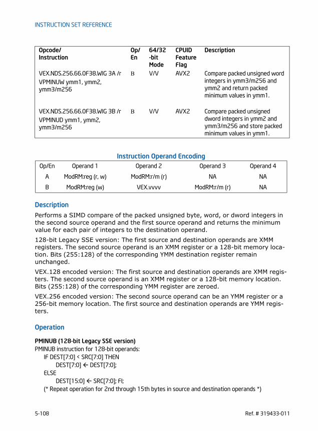
INSTRUCTION SET REFERENCE
Instruction Operand Encoding
Description
Performs a SIMD compare of the packed unsigned byte, word, or dword integers in the second source operand and the first source operand and returns the minimum value for each pair of integers to the destination operand. 128-bit Legacy SSE version: The first source and destination operands are XMM registers. The second source operand is an XMM register or a 128-bit memory loca-tion. Bits (255:128) of the corresponding YMM destination register remain unchanged.VEX.128 encoded version: The first source and destination operands are XMM regis-ters. The second source operand is an XMM register or a 128-bit memory location. Bits (255:128) of the corresponding YMM register are zeroed.VEX.256 encoded version: The second source operand can be an YMM register or a 256-bit memory location. The first source and destination operands are YMM regis-ters.
Operation
PMINUB (128-bit Legacy SSE version)PMINUB instruction for 128-bit operands:
IF DEST[7:0] < SRC[7:0] THENDEST[7:0] DEST[7:0];
ELSEDEST[15:0] SRC[7:0]; FI;
(* Repeat operation for 2nd through 15th bytes in source and destination operands *)
VEX.NDS.256.66.0F38.WIG 3A /r B V/V AVX2 Compare packed unsigned word integers in ymm3/m256 and ymm2 and return packed minimum values in ymm1.
VPMINUW ymm1, ymm2, ymm3/m256
VEX.NDS.256.66.0F38.WIG 3B /r B V/V AVX2 Compare packed unsigned dword integers in ymm2 and ymm3/m256 and store packed minimum values in ymm1.
VPMINUD ymm1, ymm2, ymm3/m256
Op/En Operand 1 Operand 2 Operand 3 Operand 4
A ModRM:reg (r, w) ModRM:r/m (r) NA NA
B ModRM:reg (w) VEX.vvvv ModRM:r/m (r) NA
Opcode/Instruction
Op/ En
64/32-bit Mode
CPUID Feature Flag
Description
5-108 Ref. # 319433-011

INSTRUCTION SET REFERENCE
IF DEST[127:120] < SRC[127:120] THENDEST[127:120] DEST[127:120];
ELSEDEST[127:120] SRC[127:120]; FI;
DEST[VLMAX:128] (Unmodified)
VPMINUB (VEX.128 encoded version)VPMINUB instruction for 128-bit operands:
IF SRC1[7:0] < SRC2[7:0] THENDEST[7:0] SRC1[7:0];
ELSEDEST[7:0] SRC2[7:0]; FI;
(* Repeat operation for 2nd through 15th bytes in source and destination operands *)IF SRC1[127:120] < SRC2[127:120] THEN
DEST[127:120] SRC1[127:120];ELSE
DEST[127:120] SRC2[127:120]; FI;DEST[VLMAX:128] 0
VPMINUB (VEX.256 encoded version)VPMINUB instruction for 128-bit operands:
IF SRC1[7:0] < SRC2[7:0] THENDEST[7:0] SRC1[7:0];
ELSEDEST[15:0] SRC2[7:0]; FI;
(* Repeat operation for 2nd through 31st bytes in source and destination operands *)IF SRC1[255:248] < SRC2[255:248] THEN
DEST[255:248] SRC1[255:248];ELSE
DEST[255:248] SRC2[255:248]; FI;
PMINUW (128-bit Legacy SSE version)PMINUW instruction for 128-bit operands:
IF DEST[15:0] < SRC[15:0] THENDEST[15:0] DEST[15:0];
ELSEDEST[15:0] SRC[15:0]; FI;
(* Repeat operation for 2nd through 7th words in source and destination operands *)IF DEST[127:112] < SRC[127:112] THEN
DEST[127:112] DEST[127:112];ELSE
DEST[127:112] SRC[127:112]; FI;DEST[VLMAX:128] (Unmodified)
Ref. # 319433-011 5-109

INSTRUCTION SET REFERENCE
VPMINUW (VEX.128 encoded version)VPMINUW instruction for 128-bit operands:
IF SRC1[15:0] < SRC2[15:0] THENDEST[15:0] SRC1[15:0];
ELSEDEST[15:0] SRC2[15:0]; FI;
(* Repeat operation for 2nd through 7th words in source and destination operands *)IF SRC1[127:112] < SRC2[127:112] THEN
DEST[127:112] SRC1[127:112];ELSE
DEST[127:112] SRC2[127:112]; FI;DEST[VLMAX:128] 0
VPMINUW (VEX.256 encoded version)VPMINUW instruction for 128-bit operands:
IF SRC1[15:0] < SRC2[15:0] THENDEST[15:0] SRC1[15:0];
ELSEDEST[15:0] SRC2[15:0]; FI;
(* Repeat operation for 2nd through 15th words in source and destination operands *)IF SRC1[255:240] < SRC2[255:240] THEN
DEST[255:240] SRC1[255:240];ELSE
DEST[255:240] SRC2[255:240]; FI;
PMINUD (128-bit Legacy SSE version)PMINUD instruction for 128-bit operands:
IF DEST[31:0] < SRC[31:0] THENDEST[31:0] DEST[31:0];
ELSEDEST[31:0] SRC[31:0]; FI;
(* Repeat operation for 2nd through 7th words in source and destination operands *)IF DEST[127:95] < SRC[127:95] THEN
DEST[127:95] DEST[127:95];ELSE
DEST[127:95] SRC[127:95]; FI;DEST[VLMAX:128] (Unmodified)
VPMINUD (VEX.128 encoded version)VPMINUD instruction for 128-bit operands:
IF SRC1[31:0] < SRC2[31:0] THENDEST[31:0] SRC1[31:0];
ELSE
5-110 Ref. # 319433-011

INSTRUCTION SET REFERENCE
DEST[31:0] SRC2[31:0]; FI;(* Repeat operation for 2nd through 3rd dwords in source and destination operands *)IF SRC1[127:95] < SRC2[127:95] THEN
DEST[127:95] SRC1[127:95];ELSE
DEST[127:95] SRC2[127:95]; FI;DEST[VLMAX:128] 0
VPMINUD (VEX.256 encoded version)VPMINUD instruction for 128-bit operands:
IF SRC1[31:0] < SRC2[31:0] THENDEST[31:0] SRC1[31:0];
ELSEDEST[31:0] SRC2[31:0]; FI;
(* Repeat operation for 2nd through 7th dwords in source and destination operands *)IF SRC1[255:224] < SRC2[255:224] THEN
DEST[255:224] SRC1[255:224];ELSE
DEST[255:224] SRC2[255:224]; FI;
Intel C/C++ Compiler Intrinsic Equivalent
(V)PMINUB __m128i _mm_min_epu8 ( __m128i a, __m128i b)
(V)PMINUW __m128i _mm_min_epu16 ( __m128i a, __m128i b);
(V)PMINUD __m128i _mm_min_epu32 ( __m128i a, __m128i b);
VPMINUB __m256i _mm256_min_epu8 ( __m256i a, __m256i b)
VPMINUW __m256i _mm256_min_epu16 ( __m256i a, __m256i b);
VPMINUD __m256i _mm256_min_epu32 ( __m256i a, __m256i b);
SIMD Floating-Point Exceptions
None
Other ExceptionsSee Exceptions Type 4
Ref. # 319433-011 5-111

INSTRUCTION SET REFERENCE
PMOVMSKB- Move Byte Mask
Instruction Operand Encoding
Description
Creates a mask made up of the most significant bit of each byte of the source operand (second operand) and stores the result in the low word or dword of the destination operand (first operand). The source operand is an XMM register; the destination operand is a general-purpose register. The mask is 16-bits for 128-bit source operand and 32-bits for 256-bit source operand. The destination operand is a general-purpose register. In 64-bit mode the default operand size of the destination operand is 64 bits. Bits 63:32 are filled with zero if the source operand is a 256-bit YMM register. The upper bits above bit 15 are filled with zeros if the source operand is a 128-bit XMM register. REX.W is ignoredVEX.128 encoded version: The source operand is XMM register.VEX.256 encoded version: The source operand is YMM register.Note: In VEX encoded versions VEX.vvvv is reserved and must be 1111b otherwise instructions will #UD.
Operation
VPMOVMSKB instruction with 256-bit source operand and r32:r32[0] SRC[7];r32[1] SRC[15];
Opcode/Instruction
Op/ En
64/32-bit Mode
CPUID Feature Flag
Description
66 0F D7 /r A V/V SSE2 Move a 16-bit mask of xmm1 to reg. The upper bits of r32 or r64 are filled with zeros.
PMOVMSKB reg, xmm1
VEX.128.66.0F.WIG D7 /r A V/V AVX Move a 16-bit mask of xmm1 to reg. The upper bits of r32 or r64 are filled with zeros.
VPMOVMSKB reg, xmm1
VEX.256.66.0F.WIG D7 /r A V/V AVX2 Move a 32-bit mask of ymm1 to reg. The upper bits of r64 are filled with zeros.
VPMOVMSKB reg, ymm1
Op/En Operand 1 Operand 2 Operand 3 Operand 4
A ModRM:reg (w) ModRM:r/m (r) NA NA
5-112 Ref. # 319433-011

INSTRUCTION SET REFERENCE
(* Repeat operation for bytes 3rd through 31*)r32[31] SRC[255];
VPMOVMSKB instruction with 256-bit source operand and r64:r64[0] SRC[7];r64[1] SRC[15];(* Repeat operation for bytes 2 through 31*)r64[31] SRC[255];r64[63:32] ZERO_FILL;
PMOVMSKB instruction with 128-bit source operand and r32:r32[0] SRC[7];r32[1] SRC[15];(* Repeat operation for bytes 2 through 14 *)r32[15] SRC[127];r32[31:16] ZERO_FILL;
PMOVMSKB instruction with 128-bit source operand and r64:r64[0] SRC[7];r64[1] SRC[15];(* Repeat operation for bytes 2 through 14 *)r64[15] SRC[127];r64[63:16] ZERO_FILL;
Intel C/C++ Compiler Intrinsic Equivalent
(V)PMOVMSKB int _mm_movemask_epi8 ( __m128i a)
VPMOVMSKB int _mm256_movemask_epi8 ( __m256i a)
SIMD Floating-Point Exceptions
None
Other ExceptionsSee Exceptions Type 7
Ref. # 319433-011 5-113

INSTRUCTION SET REFERENCE
PMOVSX - Packed Move with Sign Extend Opcode/Instruction
Op/ En
64/32-bit Mode
CPUID Feature Flag
Description
66 0f 38 20 /r A V/V SSE4_1 Sign extend 8 packed 8-bit inte-gers in the low 8 bytes of xmm2/m64 to 8 packed 16-bit integers in xmm1
PMOVSXBW xmm1, xmm2/m64
66 0f 38 21 /r A V/V SSE4_1 Sign extend 4 packed 8-bit inte-gers in the low 4 bytes of xmm2/m32 to 4 packed 32-bit integers in xmm1
PMOVSXBD xmm1, xmm2/m32
66 0f 38 22 /r A V/V SSE4_1 Sign extend 2 packed 8-bit inte-gers in the low 2 bytes of xmm2/m16 to 2 packed 64-bit integers in xmm1
PMOVSXBQ xmm1, xmm2/m16
66 0f 38 23/r A V/V SSE4_1 Sign extend 4 packed 16-bit integers in the low 8 bytes of xmm2/m64 to 4 packed 32-bit integers in xmm1
PMOVSXWD xmm1, xmm2/m64
66 0f 38 24 /r A V/V SSE4_1 Sign extend 2 packed 16-bit integers in the low 4 bytes of xmm2/m32 to 2 packed 64-bit integers in xmm1
PMOVSXWQ xmm1, xmm2/m32
66 0f 38 25 /r A V/V SSE4_1 Sign extend 2 packed 32-bit integers in the low 8 bytes of xmm2/m64 to 2 packed 64-bit integers in xmm1
PMOVSXDQ xmm1, xmm2/m64
VEX.128.66.0F38.WIG 20 /r A V/V AVX Sign extend 8 packed 8-bit inte-gers in the low 8 bytes of xmm2/m64 to 8 packed 16-bit integers in xmm1
VPMOVSXBW xmm1, xmm2/m64
VEX.128.66.0F38.WIG 21 /r A V/V AVX Sign extend 4 packed 8-bit inte-gers in the low 4 bytes of xmm2/m32 to 4 packed 32-bit integers in xmm1
VPMOVSXBD xmm1, xmm2/m32
5-114 Ref. # 319433-011

INSTRUCTION SET REFERENCE
VEX.128.66.0F38.WIG 22 /r A V/V AVX Sign extend 2 packed 8-bit inte-gers in the low 2 bytes of xmm2/m16 to 2 packed 64-bit integers in xmm1
VPMOVSXBQ xmm1, xmm2/m16
VEX.128.66.0F38.WIG 23 /r A V/V AVX Sign extend 4 packed 16-bit integers in the low 8 bytes of xmm2/m64 to 4 packed 32-bit integers in xmm1
VPMOVSXWD xmm1, xmm2/m64
VEX.128.66.0F38.WIG 24 /r A V/V AVX Sign extend 2 packed 16-bit integers in the low 4 bytes of xmm2/m32 to 2 packed 64-bit integers in xmm1
VPMOVSXWQ xmm1, xmm2/m32
VEX.128.66.0F38.WIG 25 /r A V/V AVX Sign extend 2 packed 32-bit integers in the low 8 bytes of xmm2/m64 to 2 packed 64-bit integers in xmm1
VPMOVSXDQ xmm1, xmm2/m64
VEX.256.66.0F38.WIG 20 /r A V/V AVX2 Sign extend 16 packed 8-bit integers in xmm2/m128 to 16 packed 16-bit integers in ymm1
VPMOVSXBW ymm1, xmm2/m128
VEX.256.66.0F38.WIG 21 /r A V/V AVX2 Sign extend 8 packed 8-bit inte-gers in the low 8 bytes of xmm2/m64 to 8 packed 32-bit integers in ymm1
VPMOVSXBD ymm1, xmm2/m64
VEX.256.66.0F38.WIG 22 /r A V/V AVX2 Sign extend 4 packed 8-bit inte-gers in the low 4 bytes of xmm2/m32 to 4 packed 64-bit integers in ymm1
VPMOVSXBQ ymm1, xmm2/m32
VEX.256.66.0F38.WIG 23 /r A V/V AVX2 Sign extend 8 packed 16-bit integers in the low 16 bytes of xmm2/m128 to 8 packed 32-bit integers in ymm1
VPMOVSXWD ymm1, xmm2/m128
Opcode/Instruction
Op/ En
64/32-bit Mode
CPUID Feature Flag
Description
Ref. # 319433-011 5-115

INSTRUCTION SET REFERENCE
Instruction Operand Encoding
Description
Packed byte, word, or dword integers in the low bytes of the source operand (second operand) are sign extended to word, dword, or quadword integers and stored in packed signed bytes the destination operand.128-bit Legacy SSE version: Bits (255:128) of the corresponding YMM destination register remain unchanged.VEX.128 encoded version: Bits (255:128) of the corresponding YMM register are zeroed.VEX.256 encoded version: The destination register is YMM Register.Note: In VEX encoded versions VEX.vvvv is reserved and must be 1111b otherwise instructions will #UD.
Operation
Packed_Sign_Extend_BYTE_to_WORD(DEST, SRC)DEST[15:0] SignExtend(SRC[7:0]);DEST[31:16] SignExtend(SRC[15:8]);DEST[47:32] SignExtend(SRC[23:16]);DEST[63:48] SignExtend(SRC[31:24]);DEST[79:64] SignExtend(SRC[39:32]);DEST[95:80] SignExtend(SRC[47:40]);DEST[111:96] SignExtend(SRC[55:48]);DEST[127:112] SignExtend(SRC[63:56]);
Packed_Sign_Extend_BYTE_to_DWORD(DEST, SRC)
VEX.256.66.0F38.WIG 24 /r A V/V AVX2 Sign extend 4 packed 16-bit integers in the low 8 bytes of xmm2/m64 to 4 packed 64-bit integers in ymm1
VPMOVSXWQ ymm1, xmm2/m64
VEX.256.66.0F38.WIG 25 /r A V/V AVX2 Sign extend 4 packed 32-bit integers in the low 16 bytes of xmm2/m128 to 4 packed 64-bit integers in ymm1
VPMOVSXDQ ymm1, xmm2/m128
Op/En Operand 1 Operand 2 Operand 3 Operand 4
A ModRM:reg (w) ModRM:r/m (r) NA NA
Opcode/Instruction
Op/ En
64/32-bit Mode
CPUID Feature Flag
Description
5-116 Ref. # 319433-011

INSTRUCTION SET REFERENCE
DEST[31:0] SignExtend(SRC[7:0]);DEST[63:32] SignExtend(SRC[15:8]);DEST[95:64] SignExtend(SRC[23:16]);DEST[127:96] SignExtend(SRC[31:24]);
Packed_Sign_Extend_BYTE_to_QWORD(DEST, SRC)DEST[63:0] SignExtend(SRC[7:0]);DEST[127:64] SignExtend(SRC[15:8]);
Packed_Sign_Extend_WORD_to_DWORD(DEST, SRC)DEST[31:0] SignExtend(SRC[15:0]);DEST[63:32] SignExtend(SRC[31:16]);DEST[95:64] SignExtend(SRC[47:32]);DEST[127:96] SignExtend(SRC[63:48]);
Packed_Sign_Extend_WORD_to_QWORD(DEST, SRC)DEST[63:0] SignExtend(SRC[15:0]);DEST[127:64] SignExtend(SRC[31:16]);
Packed_Sign_Extend_DWORD_to_QWORD(DEST, SRC)DEST[63:0] SignExtend(SRC[31:0]);DEST[127:64] SignExtend(SRC[63:32]);
VPMOVSXBW (VEX.256 encoded version)Packed_Sign_Extend_BYTE_to_WORD(DEST[127:0], SRC[63:0])Packed_Sign_Extend_BYTE_to_WORD(DEST[255:128], SRC[127:64])
VPMOVSXBD (VEX.256 encoded version)Packed_Sign_Extend_BYTE_to_DWORD(DEST[127:0], SRC[31:0])Packed_Sign_Extend_BYTE_to_DWORD(DEST[255:128], SRC[63:32])
VPMOVSXBQ (VEX.256 encoded version)Packed_Sign_Extend_BYTE_to_QWORD(DEST[127:0], SRC[15:0])Packed_Sign_Extend_BYTE_to_QWORD(DEST[255:128], SRC[31:16])
VPMOVSXWD (VEX.256 encoded version)Packed_Sign_Extend_WORD_to_DWORD(DEST[127:0], SRC[63:0])Packed_Sign_Extend_WORD_to_DWORD(DEST[255:128], SRC[127:64])
VPMOVSXWQ (VEX.256 encoded version)Packed_Sign_Extend_WORD_to_QWORD(DEST[127:0], SRC[31:0])Packed_Sign_Extend_WORD_to_QWORD(DEST[255:128], SRC[63:32])
Ref. # 319433-011 5-117

INSTRUCTION SET REFERENCE
VPMOVSXDQ (VEX.256 encoded version)Packed_Sign_Extend_DWORD_to_QWORD(DEST[127:0], SRC[63:0])Packed_Sign_Extend_DWORD_to_QWORD(DEST[255:128], SRC[127:64])
VPMOVSXBW (VEX.128 encoded version)Packed_Sign_Extend_BYTE_to_WORDDEST[127:0], SRC[127:0]()DEST[VLMAX:128] 0
VPMOVSXBD (VEX.128 encoded version)Packed_Sign_Extend_BYTE_to_DWORD(DEST[127:0], SRC[127:0])DEST[VLMAX:128] 0
VPMOVSXBQ (VEX.128 encoded version)Packed_Sign_Extend_BYTE_to_QWORD(DEST[127:0], SRC[127:0])DEST[VLMAX:128] 0
VPMOVSXWD (VEX.128 encoded version)Packed_Sign_Extend_WORD_to_DWORD(DEST[127:0], SRC[127:0])DEST[VLMAX:128] 0
VPMOVSXWQ (VEX.128 encoded version)Packed_Sign_Extend_WORD_to_QWORD(DEST[127:0], SRC[127:0])DEST[VLMAX:128] 0
VPMOVSXDQ (VEX.128 encoded version)Packed_Sign_Extend_DWORD_to_QWORD(DEST[127:0], SRC[127:0])DEST[VLMAX:128] 0
PMOVSXBWPacked_Sign_Extend_BYTE_to_WORD(DEST[127:0], SRC[127:0])DEST[VLMAX:128] (Unmodified)
PMOVSXBDPacked_Sign_Extend_BYTE_to_DWORD(DEST[127:0], SRC[127:0])DEST[VLMAX:128] (Unmodified)
PMOVSXBQPacked_Sign_Extend_BYTE_to_QWORD(DEST[127:0], SRC[127:0])DEST[VLMAX:128] (Unmodified)
PMOVSXWDPacked_Sign_Extend_WORD_to_DWORD(DEST[127:0], SRC[127:0])DEST[VLMAX:128] (Unmodified)
5-118 Ref. # 319433-011

INSTRUCTION SET REFERENCE
PMOVSXWQPacked_Sign_Extend_WORD_to_QWORD(DEST[127:0], SRC[127:0])DEST[VLMAX:128] (Unmodified)
PMOVSXDQPacked_Sign_Extend_DWORD_to_QWORD(DEST[127:0], SRC[127:0])DEST[VLMAX:128] (Unmodified)
Intel C/C++ Compiler Intrinsic Equivalent
(V)PMOVSXBW __m128i _mm_cvtepi8_epi16 ( __m128i a);
(V)PMOVSXBD __m128i _mm_cvtepi8_epi32 ( __m128i a);
(V)PMOVSXBQ __m128i _mm_cvtepi8_epi64 ( __m128i a);
(V)PMOVSXWD __m128i _mm_cvtepi16_epi32 ( __m128i a);
(V)PMOVSXWQ __m128i _mm_cvtepi16_epi64 ( __m128i a);
(V)PMOVSXDQ __m128i _mm_cvtepi32_epi64 ( __m128i a);
VPMOVSXBW __m256i _mm256_cvtepi8_epi16 ( __m128i a);
VPMOVSXBD __m256i _mm256_cvtepi8_epi32 ( __m128i a);
VPMOVSXBQ __m256i _mm256_cvtepi8_epi64 ( __m128i a);
VPMOVSXWD __m256i _mm256_cvtepi16_epi32 ( __m128i a);
VPMOVSXWQ __m256i _mm256_cvtepi16_epi64 ( __m128i a);
VPMOVSXDQ __m256i _mm256_cvtepi32_epi64 ( __m128i a);
SIMD Floating-Point Exceptions
None
Other ExceptionsSee Exceptions Type 5
Ref. # 319433-011 5-119

INSTRUCTION SET REFERENCE
PMOVZX - Packed Move with Zero Extend Opcode/Instruction
Op/ En
64/32-bit Mode
CPUID Feature Flag
Description
66 0f 38 30 /r A V/V SSE4_1 Zero extend 8 packed 8-bit integers in the low 8 bytes of xmm2/m64 to 8 packed 16-bit integers in xmm1
PMOVZXBW xmm1, xmm2/m64
66 0f 38 31 /r A V/V SSE4_1 Zero extend 4 packed 8-bit integers in the low 4 bytes of xmm2/m32 to 4 packed 32-bit integers in xmm1
PMOVZXBD xmm1, xmm2/m32
66 0f 38 32 /r A V/V SSE4_1 Zero extend 2 packed 8-bit integers in the low 2 bytes of xmm2/m16 to 2 packed 64-bit integers in xmm1
PMOVZXBQ xmm1, xmm2/m16
66 0f 38 33 /r A V/V SSE4_1 Zero extend 4 packed 16-bit integers in the low 8 bytes of xmm2/m64 to 4 packed 32-bit integers in xmm1
PMOVZXWD xmm1, xmm2/m64
66 0f 38 34 /r A V/V SSE4_1 Zero extend 2 packed 16-bit integers in the low 4 bytes of xmm2/m32 to 2 packed 64-bit integers in xmm1
PMOVZXWQ xmm1, xmm2/m32
66 0f 38 35 /r A V/V SSE4_1 Zero extend 2 packed 32-bit integers in the low 8 bytes of xmm2/m64 to 2 packed 64-bit integers in xmm1
PMOVZXDQ xmm1, xmm2/m64
VEX.128.66.0F38.WIG 30 /r A V/V AVX Zero extend 8 packed 8-bit integers in the low 8 bytes of xmm2/m64 to 8 packed 16-bit integers in xmm1
VPMOVZXBW xmm1, xmm2/m64
VEX.128.66.0F38.WIG 31 /r A V/V AVX Zero extend 4 packed 8-bit integers in the low 4 bytes of xmm2/m32 to 4 packed 32-bit integers in xmm1
VPMOVZXBD xmm1, xmm2/m32
5-120 Ref. # 319433-011

INSTRUCTION SET REFERENCE
VEX.128.66.0F38.WIG 32 /r A V/V AVX Zero extend 2 packed 8-bit integers in the low 2 bytes of xmm2/m16 to 2 packed 64-bit integers in xmm1
VPMOVZXBQ xmm1, xmm2/m16
VEX.128.66.0F38.WIG 33 /r A V/V AVX Zero extend 4 packed 16-bit integers in the low 8 bytes of xmm2/m64 to 4 packed 32-bit integers in xmm1
VPMOVZXWD xmm1, xmm2/m64
VEX.128.66.0F38.WIG 34 /r A V/V AVX Zero extend 2 packed 16-bit integers in the low 4 bytes of xmm2/m32 to 2 packed 64-bit integers in xmm1
VPMOVZXWQ xmm1, xmm2/m32
VEX.128.66.0F38.WIG 35 /r A V/V AVX Zero extend 2 packed 32-bit integers in the low 8 bytes of xmm2/m64 to 2 packed 64-bit integers in xmm1
VPMOVZXDQ xmm1, xmm2/m64
VEX.256.66.0F38.WIG 30 /r A V/V AVX2 Zero extend 16 packed 8-bit integers in the low 16 bytes of xmm2/m128 to 16 packed 16-bit integers in ymm1
VPMOVZXBW ymm1, xmm2/m128
VEX.256.66.0F38.WIG 31 /r A V/V AVX2 Zero extend 8 packed 8-bit integers in the low 8 bytes of xmm2/m64 to 8 packed 32-bit integers in ymm1
VPMOVZXBD ymm1, xmm2/m64
VEX.256.66.0F38.WIG 32 /r A V/V AVX2 Zero extend 4 packed 8-bit integers in the low 4 bytes of xmm2/m32 to 4 packed 64-bit integers in ymm1
VPMOVZXBQ ymm1, xmm2/m32
VEX.256.66.0F38.WIG 33 /r A V/V AVX2 Zero extend 8 packed 16-bit integers in the low 16 bytes of xmm2/m128 to 8 packed 32-bit integers in ymm1
VPMOVZXWD ymm1, xmm2/m128
Opcode/Instruction
Op/ En
64/32-bit Mode
CPUID Feature Flag
Description
Ref. # 319433-011 5-121

INSTRUCTION SET REFERENCE
Instruction Operand Encoding
Description
Packed byte, word, or dword integers in the low bytes of the source operand (second operand) are zero extended to word, dword, or quadword integers and stored in packed signed bytes the destination operand.128-bit Legacy SSE version: Bits (255:128) of the corresponding YMM destination register remain unchanged.VEX.128 encoded version: Bits (255:128) of the corresponding YMM register are zeroed.VEX.256 encoded version: The destination register is YMM Register.Note: In VEX encoded versions VEX.vvvv is reserved and must be 1111b otherwise instructions will #UD.
Operation
Packed_Zero_Extend_BYTE_to_WORD(DEST, SRC)DEST[15:0] ZeroExtend(SRC[7:0]);DEST[31:16] ZeroExtend(SRC[15:8]);DEST[47:32] ZeroExtend(SRC[23:16]);DEST[63:48] ZeroExtend(SRC[31:24]);DEST[79:64] ZeroExtend(SRC[39:32]);DEST[95:80] ZeroExtend(SRC[47:40]);DEST[111:96] ZeroExtend(SRC[55:48]);DEST[127:112] ZeroExtend(SRC[63:56]);
Packed_Zero_Extend_BYTE_to_DWORD(DEST, SRC)
VEX.256.66.0F38.WIG 34 /r A V/V AVX2 Zero extend 4 packed 16-bit integers in the low 8 bytes of xmm2/m64 to 4 packed 64-bit integers in xmm1
VPMOVZXWQ ymm1, xmm2/m64
VEX.256.66.0F38.WIG 35 /r A V/V AVX2 Zero extend 4 packed 32-bit integers in the low 16 bytes of xmm2/m128 to 4 packed 64-bit integers in ymm1
VPMOVZXDQ ymm1, xmm2/m128
Op/En Operand 1 Operand 2 Operand 3 Operand 4
A ModRM:reg (w) ModRM:r/m (r) NA NA
Opcode/Instruction
Op/ En
64/32-bit Mode
CPUID Feature Flag
Description
5-122 Ref. # 319433-011

INSTRUCTION SET REFERENCE
DEST[31:0] ZeroExtend(SRC[7:0]);DEST[63:32] ZeroExtend(SRC[15:8]);DEST[95:64] ZeroExtend(SRC[23:16]);DEST[127:96] ZeroExtend(SRC[31:24]);
Packed_Zero_Extend_BYTE_to_QWORD(DEST, SRC)DEST[63:0] ZeroExtend(SRC[7:0]);DEST[127:64] ZeroExtend(SRC[15:8]);
Packed_Zero_Extend_WORD_to_DWORD(DEST, SRC)DEST[31:0] ZeroExtend(SRC[15:0]);DEST[63:32] ZeroExtend(SRC[31:16]);DEST[95:64] ZeroExtend(SRC[47:32]);DEST[127:96] ZeroExtend(SRC[63:48]);
Packed_Zero_Extend_WORD_to_QWORD(DEST, SRC)DEST[63:0] ZeroExtend(SRC[15:0]);DEST[127:64] ZeroExtend(SRC[31:16]);
Packed_Zero_Extend_DWORD_to_QWORD(DEST, SRC)DEST[63:0] ZeroExtend(SRC[31:0]);DEST[127:64] ZeroExtend(SRC[63:32]);
VPMOVZXBW (VEX.256 encoded version)Packed_Zero_Extend_BYTE_to_WORD(DEST[127:0], SRC[63:0])Packed_Zero_Extend_BYTE_to_WORD(DEST[255:128], SRC[127:64])
VPMOVZXBD (VEX.256 encoded version)Packed_Zero_Extend_BYTE_to_DWORD(DEST[127:0], SRC[31:0])Packed_Zero_Extend_BYTE_to_DWORD(DEST[255:128], SRC[63:32])
VPMOVZXBQ (VEX.256 encoded version)Packed_Zero_Extend_BYTE_to_QWORD(DEST[127:0], SRC[15:0])Packed_Zero_Extend_BYTE_to_QWORD(DEST[255:128], SRC[31:16])
VPMOVZXWD (VEX.256 encoded version)Packed_Zero_Extend_WORD_to_DWORD(DEST[127:0], SRC[63:0])Packed_Zero_Extend_WORD_to_DWORD(DEST[255:128], SRC[127:64])
VPMOVZXWQ (VEX.256 encoded version)Packed_Zero_Extend_WORD_to_QWORD(DEST[127:0], SRC[31:0])Packed_Zero_Extend_WORD_to_QWORD(DEST[255:128], SRC[63:32])
Ref. # 319433-011 5-123

INSTRUCTION SET REFERENCE
VPMOVZXDQ (VEX.256 encoded version)Packed_Zero_Extend_DWORD_to_QWORD(DEST[127:0], SRC[63:0])Packed_Zero_Extend_DWORD_to_QWORD(DEST[255:128], SRC[127:64])
VPMOVZXBW (VEX.128 encoded version)Packed_Zero_Extend_BYTE_to_WORD()DEST[VLMAX:128] 0
VPMOVZXBD (VEX.128 encoded version)Packed_Zero_Extend_BYTE_to_DWORD()DEST[VLMAX:128] 0
VPMOVZXBQ (VEX.128 encoded version)Packed_Zero_Extend_BYTE_to_QWORD()DEST[VLMAX:128] 0
VPMOVZXWD (VEX.128 encoded version)Packed_Zero_Extend_WORD_to_DWORD()DEST[VLMAX:128] 0
VPMOVZXWQ (VEX.128 encoded version)Packed_Zero_Extend_WORD_to_QWORD()DEST[VLMAX:128] 0
VPMOVZXDQ (VEX.128 encoded version)Packed_Zero_Extend_DWORD_to_QWORD()DEST[VLMAX:128] 0
PMOVZXBWPacked_Zero_Extend_BYTE_to_WORD()DEST[VLMAX:128] (Unmodified)
PMOVZXBDPacked_Zero_Extend_BYTE_to_DWORD()DEST[VLMAX:128] (Unmodified)
PMOVZXBQPacked_Zero_Extend_BYTE_to_QWORD()DEST[VLMAX:128] (Unmodified)
PMOVZXWDPacked_Zero_Extend_WORD_to_DWORD()DEST[VLMAX:128] (Unmodified)
5-124 Ref. # 319433-011
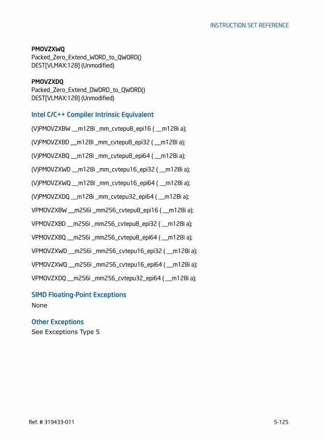
INSTRUCTION SET REFERENCE
PMOVZXWQPacked_Zero_Extend_WORD_to_QWORD()DEST[VLMAX:128] (Unmodified)
PMOVZXDQPacked_Zero_Extend_DWORD_to_QWORD()DEST[VLMAX:128] (Unmodified)
Intel C/C++ Compiler Intrinsic Equivalent
(V)PMOVZXBW __m128i _mm_cvtepu8_epi16 ( __m128i a);
(V)PMOVZXBD __m128i _mm_cvtepu8_epi32 ( __m128i a);
(V)PMOVZXBQ __m128i _mm_cvtepu8_epi64 ( __m128i a);
(V)PMOVZXWD __m128i _mm_cvtepu16_epi32 ( __m128i a);
(V)PMOVZXWQ __m128i _mm_cvtepu16_epi64 ( __m128i a);
(V)PMOVZXDQ __m128i _mm_cvtepu32_epi64 ( __m128i a);
VPMOVZXBW __m256i _mm256_cvtepu8_epi16 ( __m128i a);
VPMOVZXBD __m256i _mm256_cvtepu8_epi32 ( __m128i a);
VPMOVZXBQ __m256i _mm256_cvtepu8_epi64 ( __m128i a);
VPMOVZXWD __m256i _mm256_cvtepu16_epi32 ( __m128i a);
VPMOVZXWQ __m256i _mm256_cvtepu16_epi64 ( __m128i a);
VPMOVZXDQ __m256i _mm256_cvtepu32_epi64 ( __m128i a);
SIMD Floating-Point Exceptions
None
Other ExceptionsSee Exceptions Type 5
Ref. # 319433-011 5-125

INSTRUCTION SET REFERENCE
PMULDQ - Multiply Packed Doubleword Integers
Instruction Operand Encoding
Description
Multiplies the first source operand by the second source operand and stores the result in the destination operand. For PMULDQ and VPMULDQ (VEX.128 encoded version), the second source operand is two packed signed doubleword integers stored in the first (low) and third double-words of an XMM register or a 128-bit memory location. The first source operand is two packed signed doubleword integers stored in the first and third doublewords of an XMM register. The destination contains two packed signed quadword integers stored in an XMM register. For 128-bit memory operands, 128 bits are fetched from memory, but only the first and third doublewords are used in the computation.For VPMULDQ (VEX.256 encoded version), the second source operand is four packed signed doubleword integers stored in the first (low), third, fifth and seventh double-words of an YMM register or a 256-bit memory location. The first source operand is four packed signed doubleword integers stored in the first, third, fifth and seventh doublewords of an XMM register. The destination contains four packed signed quad-
Opcode/Instruction
Op/ En
64/32-bit Mode
CPUID Feature Flag
Description
66 0F 38 28 /r A V/V SSE4_1 Multiply packed signed double-word integers in xmm1 by packed signed doubleword inte-gers in xmm2/m128, and store the quadword results in xmm1.
PMULDQ xmm1, xmm2/m128
VEX.NDS.128.66.0F38.WIG 28 /r B V/V AVX Multiply packed signed double-word integers in xmm2 by packed signed doubleword inte-gers in xmm3/m128, and store the quadword results in xmm1.
VPMULDQ xmm1, xmm2, xmm3/m128
VEX.NDS.256.66.0F38.WIG 28 /r B V/V AVX2 Multiply packed signed double-word integers in ymm2 by packed signed doubleword inte-gers in ymm3/m256, and store the quadword results in ymm1.
VPMULDQ ymm1, ymm2, ymm3/m256
Op/En Operand 1 Operand 2 Operand 3 Operand 4
A ModRM:reg (r, w) ModRM:r/m (r) NA NA
B ModRM:reg (w) VEX.vvvv ModRM:r/m (r) NA
5-126 Ref. # 319433-011

INSTRUCTION SET REFERENCE
word integers stored in an YMM register. For 256-bit memory operands, 256 bits are fetched from memory, but only the first, third, fifth and seventh doublewords are used in the computation.When a quadword result is too large to be represented in 64 bits (overflow), the result is wrapped around and the low 64 bits are written to the destination element (that is, the carry is ignored).
128-bit Legacy SSE version: The first source and destination operands are XMM registers. The second source operand is an XMM register or a 128-bit memory loca-tion. Bits (255:128) of the corresponding YMM destination register remain unchanged.VEX.128 encoded version: The first source and destination operands are XMM regis-ters. The second source operand is an XMM register or a 128-bit memory location. Bits (255:128) of the corresponding YMM register are zeroed.VEX.256 encoded version: The second source operand can be an YMM register or a 256-bit memory location. The first source and destination operands are YMM regis-ters.
Operation
VPMULDQ (VEX.256 encoded version)DEST[63:0] SRC1[31:0] * SRC2[31:0]DEST[127:64] SRC1[95:64] * SRC2[95:64]DEST[191:128] SRC1[159:128] * SRC2[159:128]DEST[255:192] SRC1[223:192] * SRC2[223:192]
VPMULDQ (VEX.128 encoded version)DEST[63:0] SRC1[31:0] * SRC2[31:0]DEST[127:64] SRC1[95:64] * SRC2[95:64]DEST[VLMAX:128] 0
PMULDQ (128-bit Legacy SSE version)DEST[63:0] DEST[31:0] * SRC[31:0]DEST[127:64] DEST[95:64] * SRC[95:64]DEST[VLMAX:128] (Unmodified)
Intel C/C++ Compiler Intrinsic Equivalent
(V)PMULDQ __m128i _mm_mul_epi32( __m128i a, __m128i b);
VPMULDQ __m256i _mm256_mul_epi32( __m256i a, __m256i b);
SIMD Floating-Point Exceptions
None
Ref. # 319433-011 5-127

INSTRUCTION SET REFERENCE
Other ExceptionsSee Exceptions Type 4
5-128 Ref. # 319433-011

INSTRUCTION SET REFERENCE
PMULHRSW - Multiply Packed Unsigned Integers with Round and Scale
Instruction Operand Encoding
Description
PMULHRSW multiplies vertically each signed 16-bit integer from the first source operand with the corresponding signed 16-bit integer of the second source operand, producing intermediate, signed 32-bit integers. Each intermediate 32-bit integer is truncated to the 18 most significant bits. Rounding is always performed by adding 1 to the least significant bit of the 18-bit intermediate result. The final result is obtained by selecting the 16 bits immediately to the right of the most significant bit of each 18-bit intermediate result and packed to the destination operand. 128-bit Legacy SSE version: The first source and destination operands are XMM registers. The second source operand is an XMM register or a 128-bit memory loca-tion. Bits (255:128) of the corresponding YMM destination register remain unchanged.VEX.128 encoded version: The first source and destination operands are XMM regis-ters. The second source operand is an XMM register or a 128-bit memory location. Bits (255:128) of the corresponding YMM register are zeroed.VEX.256 encoded version: The second source operand can be an YMM register or a 256-bit memory location. The first source and destination operands are YMM regis-ters.
Opcode/Instruction
Op/ En
64/32-bit Mode
CPUID Feature Flag
Description
66 0F 38 0B /r A V/V SSSE3 Multiply 16-bit signed words, scale and round signed double-words, pack high 16 bits to xmm1.
PMULHRSW xmm1, xmm2/m128
VEX.NDS.128.66.0F38.WIG 0B /r B V/V AVX Multiply 16-bit signed words, scale and round signed double-words, pack high 16 bits to xmm1.
VPMULHRSW xmm1, xmm2, xmm3/m128
VEX.NDS.256.66.0F38.WIG 0B /r B V/V AVX2 Multiply 16-bit signed words, scale and round signed double-words, pack high 16 bits to ymm1.
VPMULHRSW ymm1, ymm2, ymm3/m256
Op/En Operand 1 Operand 2 Operand 3 Operand 4
A ModRM:reg (r, w) ModRM:r/m (r) NA NA
B ModRM:reg (w) VEX.vvvv ModRM:r/m (r) NA
Ref. # 319433-011 5-129
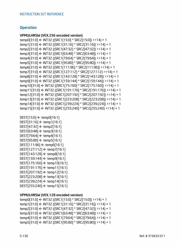
INSTRUCTION SET REFERENCE
Operation
VPMULHRSW (VEX.256 encoded version)temp0[31:0] INT32 ((SRC1[15:0] * SRC2[15:0]) >>14) + 1temp1[31:0] INT32 ((SRC1[31:16] * SRC2[31:16]) >>14) + 1temp2[31:0] INT32 ((SRC1[47:32] * SRC2[47:32]) >>14) + 1temp3[31:0] INT32 ((SRC1[63:48] * SRC2[63:48]) >>14) + 1temp4[31:0] INT32 ((SRC1[79:64] * SRC2[79:64]) >>14) + 1temp5[31:0] INT32 ((SRC1[95:80] * SRC2[95:80]) >>14) + 1temp6[31:0] INT32 ((SRC1[111:96] * SRC2[111:96]) >>14) + 1temp7[31:0] INT32 ((SRC1[127:112] * SRC2[127:112) >>14) + 1temp8[31:0] INT32 ((SRC1[143:128] * SRC2[143:128]) >>14) + 1temp9[31:0] INT32 ((SRC1[159:144] * SRC2[159:144]) >>14) + 1temp10[31:0] INT32 ((SRC1[75:160] * SRC2[175:160]) >>14) + 1temp11[31:0] INT32 ((SRC1[191:176] * SRC2[191:176]) >>14) + 1temp12[31:0] INT32 ((SRC1[207:192] * SRC2[207:192]) >>14) + 1temp13[31:0] INT32 ((SRC1[223:208] * SRC2[223:208]) >>14) + 1temp14[31:0] INT32 ((SRC1[239:224] * SRC2[239:224]) >>14) + 1temp15[31:0] INT32 ((SRC1[255:240] * SRC2[255:240) >>14) + 1
DEST[15:0] temp0[16:1]DEST[31:16] temp1[16:1]DEST[47:32] temp2[16:1]DEST[63:48] temp3[16:1]DEST[79:64] temp4[16:1]DEST[95:80] temp5[16:1]DEST[111:96] temp6[16:1]DEST[127:112] temp7[16:1]DEST[143:128] temp8[16:1]DEST[159:144] temp9[16:1]DEST[175:160] temp10[16:1]DEST[191:176] temp11[16:1]DEST[207:192] temp12[16:1]DEST[223:208] temp13[16:1]DEST[239:224] temp14[16:1]DEST[255:240] temp15[16:1]
VPMULHRSW (VEX.128 encoded version)temp0[31:0] INT32 ((SRC1[15:0] * SRC2[15:0]) >>14) + 1temp1[31:0] INT32 ((SRC1[31:16] * SRC2[31:16]) >>14) + 1temp2[31:0] INT32 ((SRC1[47:32] * SRC2[47:32]) >>14) + 1temp3[31:0] INT32 ((SRC1[63:48] * SRC2[63:48]) >>14) + 1temp4[31:0] INT32 ((SRC1[79:64] * SRC2[79:64]) >>14) + 1temp5[31:0] INT32 ((SRC1[95:80] * SRC2[95:80]) >>14) + 1
5-130 Ref. # 319433-011

INSTRUCTION SET REFERENCE
temp6[31:0] INT32 ((SRC1[111:96] * SRC2[111:96]) >>14) + 1temp7[31:0] INT32 ((SRC1[127:112] * SRC2[127:112) >>14) + 1DEST[15:0] temp0[16:1]DEST[31:16] temp1[16:1]DEST[47:32] temp2[16:1]DEST[63:48] temp3[16:1]DEST[79:64] temp4[16:1]DEST[95:80] temp5[16:1]DEST[111:96] temp6[16:1]DEST[127:112] temp7[16:1]DEST[VLMAX:128] 0
PMULHRSW (128-bit Legacy SSE version)temp0[31:0] INT32 ((DEST[15:0] * SRC[15:0]) >>14) + 1temp1[31:0] INT32 ((DEST[31:16] * SRC[31:16]) >>14) + 1temp2[31:0] INT32 ((DEST[47:32] * SRC[47:32]) >>14) + 1temp3[31:0] INT32 ((DEST[63:48] * SRC[63:48]) >>14) + 1temp4[31:0] INT32 ((DEST[79:64] * SRC[79:64]) >>14) + 1temp5[31:0] INT32 ((DEST[95:80] * SRC[95:80]) >>14) + 1temp6[31:0] INT32 ((DEST[111:96] * SRC[111:96]) >>14) + 1temp7[31:0] INT32 ((DEST[127:112] * SRC[127:112) >>14) + 1DEST[15:0] temp0[16:1]DEST[31:16] temp1[16:1]DEST[47:32] temp2[16:1]DEST[63:48] temp3[16:1]DEST[79:64] temp4[16:1]DEST[95:80] temp5[16:1]DEST[111:96] temp6[16:1]DEST[127:112] temp7[16:1]DEST[VLMAX:128] (Unmodified)
Intel C/C++ Compiler Intrinsic Equivalent
(V)PMULHRSW __m128i _mm_mulhrs_epi16 (__m128i a, __m128i b)
VPMULHRSW __m256i _mm256_mulhrs_epi16 (__m256i a, __m256i b)
SIMD Floating-Point Exceptions
None
Other ExceptionsSee Exceptions Type 4
Ref. # 319433-011 5-131

INSTRUCTION SET REFERENCE
PMULHUW - Multiply Packed Unsigned Integers and Store High Result
Instruction Operand Encoding
Description
Performs a SIMD unsigned multiply of the packed unsigned word integers in the first source operand and the second source operand, and stores the high 16 bits of each 32-bit intermediate results in the destination operand.128-bit Legacy SSE version: The first source and destination operands are XMM registers. The second source operand is an XMM register or a 128-bit memory loca-tion. Bits (255:128) of the corresponding YMM destination register remain unchanged.VEX.128 encoded version: The first source and destination operands are XMM regis-ters. The second source operand is an XMM register or a 128-bit memory location. Bits (255:128) of the corresponding YMM register are zeroed.VEX.256 encoded version: The second source operand can be an YMM register or a 256-bit memory location. The first source and destination operands are YMM regis-ters.
Operation
PMULHUW (VEX.256 encoded version)
Opcode/Instruction
Op/ En
64/32-bit Mode
CPUID Feature Flag
Description
66 0F E4 /r A V/V SSE2 Multiply the packed unsigned word integers in xmm1 and xmm2/m128, and store the high 16 bits of the results in xmm1.
PMULHUW xmm1, xmm2/m128
VEX.NDS.128.66.0F.WIG E4 /r B V/V AVX Multiply the packed unsigned word integers in xmm2 and xmm3/m128, and store the high 16 bits of the results in xmm1.
VPMULHUW xmm1, xmm2, xmm3/m128
VEX.NDS.256.66.0F.WIG E4 /r B V/V AVX2 Multiply the packed unsigned word integers in ymm2 and ymm3/m256, and store the high 16 bits of the results in ymm1.
VPMULHUW ymm1, ymm2, ymm3/m256
Op/En Operand 1 Operand 2 Operand 3 Operand 4
A ModRM:reg (r, w) ModRM:r/m (r) NA NA
B ModRM:reg (w) VEX.vvvv ModRM:r/m (r) NA
5-132 Ref. # 319433-011

INSTRUCTION SET REFERENCE
TEMP0[31:0] SRC1[15:0] * SRC2[15:0]TEMP1[31:0] SRC1[31:16] * SRC2[31:16]TEMP2[31:0] SRC1[47:32] * SRC2[47:32]TEMP3[31:0] SRC1[63:48] * SRC2[63:48]TEMP4[31:0] SRC1[79:64] * SRC2[79:64]TEMP5[31:0] SRC1[95:80] * SRC2[95:80]TEMP6[31:0] SRC1[111:96] * SRC2[111:96]TEMP7[31:0] SRC1[127:112] * SRC2[127:112]TEMP8[31:0] SRC1[143:128] * SRC2[143:128]TEMP9[31:0] SRC1[159:144] * SRC2[159:144]TEMP10[31:0] SRC1[175:160] * SRC2[175:160]TEMP11[31:0] SRC1[191:176] * SRC2[191:176]TEMP12[31:0] SRC1[207:192] * SRC2[207:192]TEMP13[31:0] SRC1[223:208] * SRC2[223:208]TEMP14[31:0] SRC1[239:224] * SRC2[239:224]TEMP15[31:0] SRC1[255:240] * SRC2[255:240]
DEST[15:0] TEMP0[31:16]DEST[31:16] TEMP1[31:16]DEST[47:32] TEMP2[31:16]DEST[63:48] TEMP3[31:16]DEST[79:64] TEMP4[31:16]DEST[95:80] TEMP5[31:16]DEST[111:96] TEMP6[31:16]DEST[127:112] TEMP7[31:16]DEST[143:128] TEMP8[31:16]DEST[159:144] TEMP9[31:16]DEST[175:160] TEMP10[31:16]DEST[191:176] TEMP11[31:16]DEST[207:192] TEMP12[31:16]DEST[223:208] TEMP13[31:16]DEST[239:224] TEMP14[31:16]DEST[255:240] TEMP15[31:16]
PMULHUW (VEX.128 encoded version)TEMP0[31:0] SRC1[15:0] * SRC2[15:0]TEMP1[31:0] SRC1[31:16] * SRC2[31:16]TEMP2[31:0] SRC1[47:32] * SRC2[47:32]TEMP3[31:0] SRC1[63:48] * SRC2[63:48]TEMP4[31:0] SRC1[79:64] * SRC2[79:64]TEMP5[31:0] SRC1[95:80] * SRC2[95:80]TEMP6[31:0] SRC1[111:96] * SRC2[111:96]TEMP7[31:0] SRC1[127:112] * SRC2[127:112]
Ref. # 319433-011 5-133

INSTRUCTION SET REFERENCE
DEST[15:0] TEMP0[31:16]DEST[31:16] TEMP1[31:16]DEST[47:32] TEMP2[31:16]DEST[63:48] TEMP3[31:16]DEST[79:64] TEMP4[31:16]DEST[95:80] TEMP5[31:16]DEST[111:96] TEMP6[31:16]DEST[127:112] TEMP7[31:16]DEST[VLMAX:128] 0
PMULHUW (128-bit Legacy SSE version)TEMP0[31:0] DEST[15:0] * SRC[15:0]TEMP1[31:0] DEST[31:16] * SRC[31:16]TEMP2[31:0] DEST[47:32] * SRC[47:32]TEMP3[31:0] DEST[63:48] * SRC[63:48]TEMP4[31:0] DEST[79:64] * SRC[79:64]TEMP5[31:0] DEST[95:80] * SRC[95:80]TEMP6[31:0] DEST[111:96] * SRC[111:96]TEMP7[31:0] DEST[127:112] * SRC[127:112]DEST[15:0] TEMP0[31:16]DEST[31:16] TEMP1[31:16]DEST[47:32] TEMP2[31:16]DEST[63:48] TEMP3[31:16]DEST[79:64] TEMP4[31:16]DEST[95:80] TEMP5[31:16]DEST[111:96] TEMP6[31:16]DEST[127:112] TEMP7[31:16]DEST[VLMAX:128] (Unmodified)
Intel C/C++ Compiler Intrinsic Equivalent
(V)PMULHUW __m128i _mm_mulhi_epu16 ( __m128i a, __m128i b)
VPMULHUW __m256i _mm256_mulhi_epu16 ( __m256i a, __m256i b)
SIMD Floating-Point Exceptions
None
Other ExceptionsSee Exceptions Type 4
5-134 Ref. # 319433-011

INSTRUCTION SET REFERENCE
PMULHW - Multiply Packed Integers and Store High Result
Instruction Operand Encoding
Description
Performs a SIMD signed multiply of the packed signed word integers in the first source operand and the second source operand, and stores the high 16 bits of each intermediate 32-bit result in the destination operand.128-bit Legacy SSE version: The first source and destination operands are XMM registers. The second source operand is an XMM register or a 128-bit memory loca-tion. Bits (255:128) of the corresponding YMM destination register remain unchanged.VEX.128 encoded version: The first source and destination operands are XMM regis-ters. The second source operand is an XMM register or a 128-bit memory location. Bits (255:128) of the corresponding YMM register are zeroed.VEX.256 encoded version: The second source operand can be an YMM register or a 256-bit memory location. The first source and destination operands are YMM regis-ters.
Operation
PMULHW (VEX.256 encoded version)
Opcode/Instruction
Op/ En
64/32-bit Mode
CPUID Feature Flag
Description
66 0F E5 /r A V/V SSE2 Multiply the packed signed word integers in xmm1 and xmm2/m128, and store the high 16 bits of the results in xmm1.
PMULHW xmm1, xmm2/m128
VEX.NDS.128.66.0F.WIG E5 /r B V/V AVX Multiply the packed signed word integers in xmm2 and xmm3/m128, and store the high 16 bits of the results in xmm1.
VPMULHW xmm1, xmm2, xmm3/m128
VEX.NDS.256.66.0F.WIG E5 /r B V/V AVX2 Multiply the packed signed word integers in ymm2 and ymm3/m256, and store the high 16 bits of the results in ymm1.
VPMULHW ymm1, ymm2, ymm3/m256
Op/En Operand 1 Operand 2 Operand 3 Operand 4
A ModRM:reg (r, w) ModRM:r/m (r) NA NA
B ModRM:reg (w) VEX.vvvv ModRM:r/m (r) NA
Ref. # 319433-011 5-135

INSTRUCTION SET REFERENCE
TEMP0[31:0] SRC1[15:0] * SRC2[15:0] (*Signed Multiplication*)TEMP1[31:0] SRC1[31:16] * SRC2[31:16]TEMP2[31:0] SRC1[47:32] * SRC2[47:32]TEMP3[31:0] SRC1[63:48] * SRC2[63:48]TEMP4[31:0] SRC1[79:64] * SRC2[79:64]TEMP5[31:0] SRC1[95:80] * SRC2[95:80]TEMP6[31:0] SRC1[111:96] * SRC2[111:96]TEMP7[31:0] SRC1[127:112] * SRC2[127:112]TEMP8[31:0] SRC1[143:128] * SRC2[143:128]TEMP9[31:0] SRC1[159:144] * SRC2[159:144]TEMP10[31:0] SRC1[175:160] * SRC2[175:160]TEMP11[31:0] SRC1[191:176] * SRC2[191:176]TEMP12[31:0] SRC1[207:192] * SRC2[207:192]TEMP13[31:0] SRC1[223:208] * SRC2[223:208]TEMP14[31:0] SRC1[239:224] * SRC2[239:224]TEMP15[31:0] SRC1[255:240] * SRC2[255:240]
DEST[15:0] TEMP0[31:16]DEST[31:16] TEMP1[31:16]DEST[47:32] TEMP2[31:16]DEST[63:48] TEMP3[31:16]DEST[79:64] TEMP4[31:16]DEST[95:80] TEMP5[31:16]DEST[111:96] TEMP6[31:16]DEST[127:112] TEMP7[31:16]DEST[143:128] TEMP8[31:16]DEST[159:144] TEMP9[31:16]DEST[175:160] TEMP10[31:16]DEST[191:176] TEMP11[31:16]DEST[207:192] TEMP12[31:16]DEST[223:208] TEMP13[31:16]DEST[239:224] TEMP14[31:16]DEST[255:240] TEMP15[31:16]
PMULHW (VEX.128 encoded version)TEMP0[31:0] SRC1[15:0] * SRC2[15:0] (*Signed Multiplication*)TEMP1[31:0] SRC1[31:16] * SRC2[31:16]TEMP2[31:0] SRC1[47:32] * SRC2[47:32]TEMP3[31:0] SRC1[63:48] * SRC2[63:48]TEMP4[31:0] SRC1[79:64] * SRC2[79:64]TEMP5[31:0] SRC1[95:80] * SRC2[95:80]TEMP6[31:0] SRC1[111:96] * SRC2[111:96]TEMP7[31:0] SRC1[127:112] * SRC2[127:112]
5-136 Ref. # 319433-011

INSTRUCTION SET REFERENCE
DEST[15:0] TEMP0[31:16]DEST[31:16] TEMP1[31:16]DEST[47:32] TEMP2[31:16]DEST[63:48] TEMP3[31:16]DEST[79:64] TEMP4[31:16]DEST[95:80] TEMP5[31:16]DEST[111:96] TEMP6[31:16]DEST[127:112] TEMP7[31:16]DEST[VLMAX:128] 0
PMULHW (128-bit Legacy SSE version)TEMP0[31:0] DEST[15:0] * SRC[15:0] (*Signed Multiplication*)TEMP1[31:0] DEST[31:16] * SRC[31:16]TEMP2[31:0] DEST[47:32] * SRC[47:32]TEMP3[31:0] DEST[63:48] * SRC[63:48]TEMP4[31:0] DEST[79:64] * SRC[79:64]TEMP5[31:0] DEST[95:80] * SRC[95:80]TEMP6[31:0] DEST[111:96] * SRC[111:96]TEMP7[31:0] DEST[127:112] * SRC[127:112]DEST[15:0] TEMP0[31:16]DEST[31:16] TEMP1[31:16]DEST[47:32] TEMP2[31:16]DEST[63:48] TEMP3[31:16]DEST[79:64] TEMP4[31:16]DEST[95:80] TEMP5[31:16]DEST[111:96] TEMP6[31:16]DEST[127:112] TEMP7[31:16]DEST[VLMAX:128] (Unmodified)
Intel C/C++ Compiler Intrinsic Equivalent
(V)PMULHW __m128i _mm_mulhi_epi16 ( __m128i a, __m128i b)
VPMULHW __m256i _mm256_mulhi_epi16 ( __m256i a, __m256i b)
SIMD Floating-Point Exceptions
None
Other ExceptionsSee Exceptions Type 4
Ref. # 319433-011 5-137

INSTRUCTION SET REFERENCE
PMULLW/PMULLD - Multiply Packed Integers and Store Low ResultOpcode/Instruction
Op/ En
64/32-bit Mode
CPUID Feature Flag
Description
66 0F D5 /r A V/V SSE2 Multiply the packed signed word integers in xmm1 and xmm2/m128, and store the low 16 bits of the results in xmm1
PMULLW xmm1, xmm2/m128
66 0F 38 40 /r A V/V SSE4_1 Multiply the packed dword signed integers in xmm1 and xmm2/m128 and store the low 32 bits of each product in xmm1
PMULLD xmm1, xmm2/m128
VEX.NDS.128.66.0F.WIG D5 /r B V/V AVX Multiply the packed signed word integers in xmm2 and xmm3/m128, and store the low 16 bits of the results in xmm1
VPMULLW xmm1, xmm2, xmm3/m128
VEX.NDS.128.66.0F38.WIG 40 /r B V/V AVX Multiply the packed dword signed integers in xmm2 and xmm3/m128 and store the low 32 bits of each product in xmm1
VPMULLD xmm1, xmm2, xmm3/m128
VEX.NDS.256.66.0F.WIG D5 /r B V/V AVX2 Multiply the packed signed word integers in ymm2 and ymm3/m256, and store the low 16 bits of the results in ymm1
VPMULLW ymm1, ymm2, ymm3/m256
VEX.NDS.256.66.0F38.WIG 40 /r B V/V AVX2 Multiply the packed dword signed integers in ymm2 and ymm3/m256 and store the low 32 bits of each product in ymm1
VPMULLD ymm1, ymm2, ymm3/m256
5-138 Ref. # 319433-011
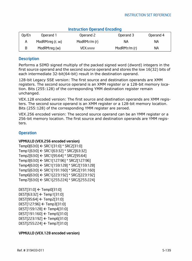
INSTRUCTION SET REFERENCE
Instruction Operand Encoding
Description
Performs a SIMD signed multiply of the packed signed word (dword) integers in the first source operand and the second source operand and stores the low 16(32) bits of each intermediate 32-bit(64-bit) result in the destination operand. 128-bit Legacy SSE version: The first source and destination operands are XMM registers. The second source operand is an XMM register or a 128-bit memory loca-tion. Bits (255:128) of the corresponding YMM destination register remain unchanged.VEX.128 encoded version: The first source and destination operands are XMM regis-ters. The second source operand is an XMM register or a 128-bit memory location. Bits (255:128) of the corresponding YMM register are zeroed.VEX.256 encoded version: The second source operand can be an YMM register or a 256-bit memory location. The first source and destination operands are YMM regis-ters.
Operation
VPMULLD (VEX.256 encoded version)Temp0[63:0] SRC1[31:0] * SRC2[31:0]Temp1[63:0] SRC1[63:32] * SRC2[63:32]Temp2[63:0] SRC1[95:64] * SRC2[95:64]Temp3[63:0] SRC1[127:96] * SRC2[127:96]Temp4[63:0] SRC1[159:128] * SRC2[159:128]Temp5[63:0] SRC1[191:160] * SRC2[191:160]Temp6[63:0] SRC1[223:192] * SRC2[223:192]Temp7[63:0] SRC1[255:224] * SRC2[255:224]
DEST[31:0] Temp0[31:0]DEST[63:32] Temp1[31:0]DEST[95:64] Temp2[31:0]DEST[127:96] Temp3[31:0]DEST[159:128] Temp4[31:0]DEST[191:160] Temp5[31:0]DEST[223:192] Temp6[31:0]DEST[255:224] Temp7[31:0]
VPMULLD (VEX.128 encoded version)
Op/En Operand 1 Operand 2 Operand 3 Operand 4
A ModRM:reg (r, w) ModRM:r/m (r) NA NA
B ModRM:reg (w) VEX.vvvv ModRM:r/m (r) NA
Ref. # 319433-011 5-139

INSTRUCTION SET REFERENCE
Temp0[63:0] SRC1[31:0] * SRC2[31:0]Temp1[63:0] SRC1[63:32] * SRC2[63:32]Temp2[63:0] SRC1[95:64] * SRC2[95:64]Temp3[63:0] SRC1[127:96] * SRC2[127:96]DEST[31:0] Temp0[31:0]DEST[63:32] Temp1[31:0]DEST[95:64] Temp2[31:0]DEST[127:96] Temp3[31:0]DEST[VLMAX:128] 0
PMULLD (128-bit Legacy SSE version)Temp0[63:0] DEST[31:0] * SRC[31:0]Temp1[63:0] DEST[63:32] * SRC[63:32]Temp2[63:0] DEST[95:64] * SRC[95:64]Temp3[63:0] DEST[127:96] * SRC[127:96]DEST[31:0] Temp0[31:0]DEST[63:32] Temp1[31:0]DEST[95:64] Temp2[31:0]DEST[127:96] Temp3[31:0]DEST[VLMAX:128] (Unmodified)
VPMULLW (VEX.256 encoded version)Temp0[31:0] SRC1[15:0] * SRC2[15:0]Temp1[31:0] SRC1[31:16] * SRC2[31:16]Temp2[31:0] SRC1[47:32] * SRC2[47:32]Temp3[31:0] SRC1[63:48] * SRC2[63:48]Temp4[31:0] SRC1[79:64] * SRC2[79:64]Temp5[31:0] SRC1[95:80] * SRC2[95:80]Temp6[31:0] SRC1[111:96] * SRC2[111:96]Temp7[31:0] SRC1[127:112] * SRC2[127:112]Temp8[31:0] SRC1[143:128] * SRC2[143:128]Temp9[31:0] SRC1[159:144] * SRC2[159:144]Temp10[31:0] SRC1[175:160] * SRC2[175:160]Temp11[31:0] SRC1[191:176] * SRC2[191:176]Temp12[31:0] SRC1[207:192] * SRC2[207:192]Temp13[31:0] SRC1[223:208] * SRC2[223:208]Temp14[31:0] SRC1[239:224] * SRC2[239:224]Temp15[31:0] SRC1[255:240] * SRC2[255:240]DEST[15:0] Temp0[15:0]DEST[31:16] Temp1[15:0]DEST[47:32] Temp2[15:0]DEST[63:48] Temp3[15:0]DEST[79:64] Temp4[15:0]
5-140 Ref. # 319433-011

INSTRUCTION SET REFERENCE
DEST[95:80] Temp5[15:0]DEST[111:96] Temp6[15:0]DEST[127:112] Temp7[15:0]DEST[143:128] Temp8[15:0]DEST[159:144] Temp9[15:0]DEST[175:160] Temp10[15:0]DEST[191:176] Temp11[15:0]DEST[207:192] TEMP12[15:0]DEST[223:208] Temp13[15:0]DEST[239:224] Temp14[15:0]DEST[255:240] Temp15[15:0]
VPMULLW (VEX.128 encoded version)Temp0[31:0] SRC1[15:0] * SRC2[15:0]Temp1[31:0] SRC1[31:16] * SRC2[31:16]Temp2[31:0] SRC1[47:32] * SRC2[47:32]Temp3[31:0] SRC1[63:48] * SRC2[63:48]Temp4[31:0] SRC1[79:64] * SRC2[79:64]Temp5[31:0] SRC1[95:80] * SRC2[95:80]Temp6[31:0] SRC1[111:96] * SRC2[111:96]Temp7[31:0] SRC1[127:112] * SRC2[127:112]DEST[15:0] Temp0[15:0]DEST[31:16] Temp1[15:0]DEST[47:32] Temp2[15:0]DEST[63:48] Temp3[15:0]DEST[79:64] Temp4[15:0]DEST[95:80] Temp5[15:0]DEST[111:96] Temp6[15:0]DEST[127:112] Temp7[15:0]DEST[VLMAX:128] 0
PMULLW (128-bit Legacy SSE version)Temp0[31:0] DEST[15:0] * SRC[15:0]Temp1[31:0] DEST[31:16] * SRC[31:16]Temp2[31:0] DEST[47:32] * SRC[47:32]Temp3[31:0] DEST[63:48] * SRC[63:48]Temp4[31:0] DEST[79:64] * SRC[79:64]Temp5[31:0] DEST[95:80] * SRC[95:80]Temp6[31:0] DEST[111:96] * SRC[111:96]Temp7[31:0] DEST[127:112] * SRC[127:112]DEST[15:0] Temp0[15:0]DEST[31:16] Temp1[15:0]DEST[47:32] Temp2[15:0]
Ref. # 319433-011 5-141

INSTRUCTION SET REFERENCE
DEST[63:48] Temp3[15:0]DEST[79:64] Temp4[15:0]DEST[95:80] Temp5[15:0]DEST[111:96] Temp6[15:0]DEST[127:112] Temp7[15:0]DEST[127:96] Temp3[31:0];DEST[VLMAX:128] (Unmodified)
Intel C/C++ Compiler Intrinsic Equivalent
(V)PMULLW __m128i _mm_mullo_epi16 ( __m128i a, __m128i b);
(V)PMULLD __m128i _mm_mullo_epi32(__m128i a, __m128i b);
VPMULLW __m256i _mm256_mullo_epi16 ( __m256i a, __m256i b);
VPMULLD __m256i _mm256_mullo_epi32(__m256i a, __m256i b);
SIMD Floating-Point Exceptions
None
Other ExceptionsSee Exceptions Type 4
5-142 Ref. # 319433-011

INSTRUCTION SET REFERENCE
PMULUDQ - Multiply Packed Unsigned Doubleword Integers
Instruction Operand Encoding
Description
Multiplies packed unsigned doubleword integers in the first source operand by the packed unsigned doubleword integers in second source operand and stores packed unsigned quadword results in the destination operand. 128-bit Legacy SSE version: The second source operand is two packed unsigned doubleword integers stored in the first (low) and third doublewords of an XMM register or a 128-bit memory location. For 128-bit memory operands, 128 bits are fetched from memory, but only the first and third doublewords are used in the computation.The first source operand is two packed unsigned doubleword integers stored in the first and third doublewords of an XMM register. The destination contains two packed unsigned quadword integers stored in an XMM register. Bits (255:128) of the corresponding YMM destination register remain unchanged.
Opcode/Instruction
Op/ En
64/32-bit Mode
CPUID Feature Flag
Description
66 0F F4 /r A V/V SSE4_1 Multiply packed unsigned double-word integers in xmm1 by packed unsigned doubleword integers in xmm2/m128, and store the quadword results in xmm1.
PMULUDQ xmm1, xmm2/m128
VEX.NDS.128.66.0F.WIG F4 /r B V/V AVX Multiply packed unsigned double-word integers in xmm2 by packed unsigned doubleword integers in xmm3/m128, and store the quadword results in xmm1.
VPMULUDQ xmm1, xmm2, xmm3/m128
VEX.NDS.256.66.0F.WIG F4 /r B V/V AVX2 Multiply packed unsigned double-word integers in ymm2 by packed unsigned doubleword integers in ymm3/m256, and store the quadword results in ymm1.
VPMULUDQ ymm1, ymm2, ymm3/m256
Op/En Operand 1 Operand 2 Operand 3 Operand 4
A ModRM:reg (r, w) ModRM:r/m (r) NA NA
B ModRM:reg (w) VEX.vvvv ModRM:r/m (r) NA
Ref. # 319433-011 5-143

INSTRUCTION SET REFERENCE
VEX.128 encoded version: The second source operand is two packed unsigned doubleword integers stored in the first (low) and third doublewords of an XMM register or a 128-bit memory location. For 128-bit memory operands, 128 bits are fetched from memory, but only the first and third doublewords are used in the computation.The first source operand is two packed unsigned doubleword integers stored in the first and third doublewords of an XMM register. The destination contains two packed unsigned quadword integers stored in an XMM register. Bits (255:128) of the corresponding YMM register are zeroed.VEX.256 encoded version: The second source operand is four packed unsigned doubleword integers stored in the first (low), third, fifth and seventh doublewords of a YMM register or a 256-bit memory location. For 256-bit memory operands, 256 bits are fetched from memory, but only the first, third, fifth and seventh doublewords are used in the computation.The first source operand is four packed unsigned double-word integers stored in the first, third, fifth and seventh doublewords of an YMM register. The destination contains four packed unaligned quadword integers stored in an YMM register.
Operation
VPMULUDQ (VEX.256 encoded version)DEST[63:0] SRC1[31:0] * SRC2[31:0]DEST[127:64] SRC1[95:64] * SRC2[95:64DEST[191:128] SRC1[159:128] * SRC2[159:128]DEST[255:192] SRC1[223:192] * SRC2[223:192]
VPMULUDQ (VEX.128 encoded version)DEST[63:0] SRC1[31:0] * SRC2[31:0]DEST[127:64] SRC1[95:64] * SRC2[95:64]DEST[VLMAX:128] 0
PMULUDQ (128-bit Legacy SSE version)DEST[63:0] DEST[31:0] * SRC[31:0]DEST[127:64] DEST[95:64] * SRC[95:64]DEST[VLMAX:128] (Unmodified)
Intel C/C++ Compiler Intrinsic Equivalent
(V)PMULUDQ __m128i _mm_mul_epu32( __m128i a, __m128i b);
VPMULUDQ __m256i _mm256_mul_epu32( __m256i a, __m256i b);
SIMD Floating-Point Exceptions
None
5-144 Ref. # 319433-011

INSTRUCTION SET REFERENCE
Other ExceptionsSee Exceptions Type 4
Ref. # 319433-011 5-145

INSTRUCTION SET REFERENCE
POR - Bitwise Logical Or
Instruction Operand Encoding
Description
Performs a bitwise logical OR operation on the second source operand and the first source operand and stores the result in the destination operand. Each bit of the result is set to 1 if either of the corresponding bits of the first and second operands are 1, otherwise it is set to 0.128-bit Legacy SSE version: The second source operand is an XMM register or a 128-bit memory location. The first source and destination operands can be XMM registers. Bits (255:128) of the corresponding YMM destination register remain unchanged.VEX.128 encoded version: The second source operand is an XMM register or a 128-bit memory location. The first source and destination operands can be XMM registers. Bits (255:128) of the corresponding YMM register are zeroed.VEX.256 encoded version: The second source operand is an YMM register or a 256-bit memory location. The first source and destination operands can be YMM registers.
Operation
VPOR (VEX.256 encoded version)DEST SRC1 OR SRC2
VPOR (VEX.128 encoded version)DEST[127:0] (SRC[127:0] OR SRC2[127:0])DEST[VLMAX:128] 0
Opcode/Instruction
Op/ En
64/32-bit Mode
CPUID Feature Flag
Description
66 0F EB /r A V/V SSE2 Bitwise OR of xmm2/m128 and xmm1.POR xmm1, xmm2/m128
VEX.NDS.128.66.0F.WIG EB /r B V/V AVX Bitwise OR of xmm2/m128 and xmm3.VPOR xmm1, xmm2, xmm3/m128
VEX.NDS.256.66.0F.WIG EB /r B V/V AVX2 Bitwise OR of ymm2/m256 and ymm3.VPOR ymm1, ymm2, ymm3/m256
Op/En Operand 1 Operand 2 Operand 3 Operand 4
A ModRM:reg (r, w) ModRM:r/m (r) NA NA
B ModRM:reg (w) VEX.vvvv ModRM:r/m (r) NA
5-146 Ref. # 319433-011

INSTRUCTION SET REFERENCE
POR (128-bit Legacy SSE version)DEST[127:0] (SRC[127:0] OR SRC2[127:0])DEST[VLMAX:128] (Unmodified)
Intel C/C++ Compiler Intrinsic Equivalent
(V)POR __m128i _mm_or_si128 ( __m128i a, __m128i b)
VPOR __m256i _mm256_or_si256 ( __m256i a, __m256i b)
SIMD Floating-Point Exceptions
none
Other ExceptionsSee Exceptions Type 4
Ref. # 319433-011 5-147

INSTRUCTION SET REFERENCE
PSADBW - Compute Sum of Absolute Differences
Instruction Operand Encoding
Description
Computes the absolute value of the difference of packed groups of 8 unsigned byte integers from the second source operand and from the first source operand. The first 8 differences are summed to produce an unsigned word integer that is stored in the low word of the destination; the second 8 differences are summed to produce an unsigned word in bits 79:64 of the destination. In case of VEX.256 encoded version, the third group of 8 differences are summed to produce an unsigned word in bits[143:128] of the destination register and the fourth group of 8 differences are
Opcode/Instruction
Op/ En
64/32-bit Mode
CPUID Feature Flag
Description
66 0F F6 /r A V/V SSE2 Computes the absolute differ-ences of the packed unsigned byte integers from xmm2 /m128 and xmm1; the 8 low differences and 8 high differences are then summed separately to produce two unsigned word integer results.
PSADBW xmm1, xmm2/m128
VEX.NDS.128.66.0F.WIG F6 /r B V/V AVX Computes the absolute differ-ences of the packed unsigned byte integers from xmm3 /m128 and xmm2; the 8 low differences and 8 high differences are then summed separately to produce two unsigned word integer results.
VPSADBW xmm1, xmm2, xmm3/m128
VEX.NDS.256.66.0F.WIG F6 /r B V/V AVX2 Computes the absolute differ-ences of the packed unsigned byte integers from ymm3 /m256 and ymm2; then each consecutive 8 differences are summed sepa-rately to produce four unsigned word integer results.
VPSADBW ymm1, ymm2, ymm3/m256
Op/En Operand 1 Operand 2 Operand 3 Operand 4
A ModRM:reg (r, w) ModRM:r/m (r) NA NA
B ModRM:reg (w) VEX.vvvv ModRM:r/m (r) NA
5-148 Ref. # 319433-011

INSTRUCTION SET REFERENCE
summed to produce an unsigned word in bits[207:192] of the destination register. The remaining words of the destination are set to 0.128-bit Legacy SSE version: The first source operand and destination register are XMM registers. The second source operand is an XMM register or a 128-bit memory location. Bits (255:128) of the corresponding YMM destination register remain unchanged.VEX.128 encoded version: The first source operand and destination register are XMM registers. The second source operand is an XMM register or a 128-bit memory loca-tion. Bits (255:128) of the corresponding YMM register are zeroed.VEX.256 encoded version: The first source operand and destination register are YMM registers. The second source operand is an YMM register or a 256-bit memory loca-tion.
Operation
VPSADBW (VEX.256 encoded version)TEMP0 ABS(SRC1[7:0] - SRC2[7:0])(* Repeat operation for bytes 2 through 30*)TEMP31 ABS(SRC1[255:248] - SRC2[255:248])DEST[15:0] SUM(TEMP0:TEMP7)DEST[63:16] 000000000000HDEST[79:64] SUM(TEMP8:TEMP15)DEST[127:80] 00000000000HDEST[143:128] SUM(TEMP16:TEMP23)DEST[191:144] 000000000000HDEST[207:192] SUM(TEMP24:TEMP31)DEST[223:208] 00000000000H
VPSADBW (VEX.128 encoded version)TEMP0 ABS(SRC1[7:0] - SRC2[7:0])(* Repeat operation for bytes 2 through 14 *)TEMP15 ABS(SRC1[127:120] - SRC2[127:120])DEST[15:0] SUM(TEMP0:TEMP7)DEST[63:16] 000000000000HDEST[79:64] SUM(TEMP8:TEMP15)DEST[127:80] 00000000000HDEST[VLMAX:128] 0
PSADBW (128-bit Legacy SSE version)TEMP0 ABS(DEST[7:0] - SRC[7:0])(* Repeat operation for bytes 2 through 14 *)TEMP15 ABS(DEST[127:120] - SRC[127:120])DEST[15:0] SUM(TEMP0:TEMP7)DEST[63:16] 000000000000H
Ref. # 319433-011 5-149

INSTRUCTION SET REFERENCE
DEST[79:64] SUM(TEMP8:TEMP15)DEST[127:80] 00000000000
DEST[VLMAX:128] (Unmodified)
Intel C/C++ Compiler Intrinsic Equivalent
(V)PSADBW __m128i _mm_sad_epu8(__m128i a, __m128i b)
VPSADBW __m256i _mm256_sad_epu8( __m256i a, __m256i b)
SIMD Floating-Point Exceptions
None
Other ExceptionsSee Exceptions Type 4
5-150 Ref. # 319433-011

INSTRUCTION SET REFERENCE
PSHUFB - Packed Shuffle Bytes
Instruction Operand Encoding
Description
PSHUFB performs in-place shuffles of bytes in the first source operand according to the shuffle control mask in the second source operand. The instruction permutes the data in the first source operand, leaving the shuffle mask unaffected. If the most significant bit (bit[7]) of each byte of the shuffle control mask is set, then constant zero is written in the result byte. Each byte in the shuffle control mask forms an index to permute the corresponding byte in the first source operand. The value of each index is the least significant 4 bits of the shuffle control byte. The first source and destination operands are XMM registers. The second source is either an XMM register or a 128-bit memory location.128-bit Legacy SSE version: The first source and destination operands are the same. Bits (255:128) of the corresponding YMM destination register remain unchanged.VEX.128 encoded version: Bits (255:128) of the destination YMM register are zeroed. VEX.256 encoded version: Bits (255:128) of the destination YMM register stores the 16-byte shuffle result of the upper 16 bytes of the first source operand, using the upper 16-bytes of the second source operand as control mask. The value of each index is for the high 128-bit lane is the least significant 4 bits of the respective shuffle control byte. The index value selects a source data element within each 128-bit lane.
Opcode/Instruction
Op/ En
64/32-bit Mode
CPUID Feature Flag
Description
66 0F 38 00 /r A V/V SSSE3 Shuffle bytes in xmm1 accord-ing to contents of xmm2/m128.PSHUFB xmm1, xmm2/m128
VEX.NDS.128.66.0F38.WIG 00 /r B V/V AVX Shuffle bytes in xmm2 accord-ing to contents of xmm3/m128.VPSHUFB xmm1, xmm2,
xmm3/m128
VEX.NDS.256.66.0F38.WIG 00 /r B V/V AVX2 Shuffle bytes in ymm2 accord-ing to contents of ymm3/m256.VPSHUFB ymm1, ymm2,
ymm3/m256
Op/En Operand 1 Operand 2 Operand 3 Operand 4
A ModRM:reg (r, w) ModRM:r/m (r) NA NA
B ModRM:reg (w) VEX.vvvv ModRM:r/m (r) NA
Ref. # 319433-011 5-151

INSTRUCTION SET REFERENCE
Operation
VPSHUFB (VEX.256 encoded version)for i = 0 to 15 {
if (SRC2[(i * 8)+7] == 1 ) thenDEST[(i*8)+7..(i*8)+0] 0;elseindex[3..0] SRC2[(i*8)+3 .. (i*8)+0];DEST[(i*8)+7..(i*8)+0] SRC1[(index*8+7)..(index*8+0)];
endifif (SRC2[128 + (i * 8)+7] == 1 ) then
DEST[128 + (i*8)+7..(i*8)+0] 0;elseindex[3..0] SRC2[128 + (i*8)+3 .. (i*8)+0];DEST[128 + (i*8)+7..(i*8)+0] SRC1[128 + (index*8+7)..(index*8+0)];
endif}
VPSHUFB (VEX.128 encoded version)for i = 0 to 15 {
if (SRC2[(i * 8)+7] == 1 ) thenDEST[(i*8)+7..(i*8)+0] 0;elseindex[3..0] SRC2[(i*8)+3 .. (i*8)+0];DEST[(i*8)+7..(i*8)+0] SRC1[(index*8+7)..(index*8+0)];
endif}DEST[VLMAX:128] 0
PSHUFB (128-bit Legacy SSE version)for i = 0 to 15 {
if (SRC[(i * 8)+7] == 1 ) thenDEST[(i*8)+7..(i*8)+0] 0;elseindex[3..0] SRC[(i*8)+3 .. (i*8)+0];DEST[(i*8)+7..(i*8)+0] DEST[(index*8+7)..(index*8+0)];
endif}DEST[VLMAX:128] (Unmodified)
Intel C/C++ Compiler Intrinsic Equivalent
(V)PSHUFB __m128i _mm_shuffle_epi8(__m128i a, __m128i b)
5-152 Ref. # 319433-011

INSTRUCTION SET REFERENCE
VPSHUFB __m256i _mm256_shuffle_epi8(__m256i a, __m256i b)
SIMD Floating-Point Exceptions
None
Other ExceptionsSee Exceptions Type 4
Ref. # 319433-011 5-153

INSTRUCTION SET REFERENCE
PSHUFD - Shuffle Packed Doublewords
Instruction Operand Encoding
Description
Copies doublewords from the source operand and inserts them in the destination operand at the locations selected with the immediate control operand. Figure 5-4 shows the operation of the 256-bit VPSHUFD instruction and the encoding of the order operand. Each 2-bit field in the order operand selects the contents of one doubleword location within a 128-bit lane and copy to the target element in the desti-nation operand. For example, bits 0 and 1 of the order operand targets the first doubleword element in the low and high 128-bit lane of the destination operand for 256-bit VPSHUFD. The encoded value of bits 1:0 of the order operand (see the field encoding in Figure 5-4) determines which doubleword element (from the respective 128-bit lane) of the source operand will be copied to doubleword 0 of the destination operand. For 128-bit operation, only the low 128-bit lane are operative. The source operand can be an XMM register or a 128-bit memory location. The destination operand is an XMM register. The order operand is an 8-bit immediate. Note that this instruction permits a doubleword in the source operand to be copied to more than one double-word location in the destination operand.
Opcode/Instruction
Op/ En
64/32-bit Mode
CPUID Feature Flag
Description
66 0F 70 /r ib A V/V SSE2 Shuffle the doublewords in xmm2/m128 based on the encoding in imm8 and store the result in xmm1.
PSHUFD xmm1, xmm2/m128, imm8
VEX.128.66.0F.WIG 70 /r ib A V/V AVX Shuffle the doublewords in xmm2/m128 based on the encoding in imm8 and store the result in xmm1.
VPSHUFD xmm1, xmm2/m128, imm8
VEX.256.66.0F.WIG 70 /r ib A V/V AVX2 Shuffle the doublewords in ymm2/m256 based on the encoding in imm8 and store the result in ymm1.
VPSHUFD ymm1, ymm2/m256, imm8
Op/En Operand 1 Operand 2 Operand 3 Operand 4
A ModRM:reg (w) ModRM:r/m (r) NA NA
5-154 Ref. # 319433-011

INSTRUCTION SET REFERENCE
Figure 5-4. 256-bit VPSHUFD Instruction Operation
Legacy SSE instructions: In 64-bit mode using a REX prefix in the form of REX.R permits this instruction to access additional registers (XMM8-XMM15).128-bit Legacy SSE version: Bits (255:128) of the corresponding YMM destination register remain unchanged.VEX.128 encoded version: Bits (255:128) of the corresponding YMM register are zeroed.VEX.256 encoded version: Bits (255:128) of the destination stores the shuffled results of the upper 16 bytes of the source operand using the immediate byte as the order operand.Note: In VEX encoded versions VEX.vvvv is reserved and must be 1111b otherwise instructions will #UD.
Operation
VPSHUFD (VEX.256 encoded version)DEST[31:0] (SRC[127:0] >> (ORDER[1:0] * 32))[31:0];DEST[63:32] (SRC[127:0] >> (ORDER[3:2] * 32))[31:0];DEST[95:64] (SRC[127:0] >> (ORDER[5:4] * 32))[31:0];DEST[127:96] (SRC[127:0] >> (ORDER[7:6] * 32))[31:0];DEST[159:128] (SRC[255:128] >> (ORDER[1:0] * 32))[31:0];DEST[191:160] (SRC[255:128] >> (ORDER[3:2] * 32))[31:0];DEST[223:192] (SRC[255:128] >> (ORDER[5:4] * 32))[31:0];DEST[255:224] (SRC[255:128] >> (ORDER[7:6] * 32))[31:0];
VPSHUFD (VEX.128 encoded version)
X7 X6 X5 X4SRC
DEST Y7 Y6 Y5 Y4
ORDER00B - X001B - X110B - X211B - X3
Encodingof Fields in
ORDER01234567Operand
Y3 Y2 Y1 Y0
X3 X2 X1 X0
00B - X401B - X510B - X611B - X7
Encodingof Fields in
ORDEROperand
Ref. # 319433-011 5-155

INSTRUCTION SET REFERENCE
DEST[31:0] (SRC[127:0] >> (ORDER[1:0] * 32))[31:0];DEST[63:32] (SRC[127:0] >> (ORDER[3:2] * 32))[31:0];DEST[95:64] (SRC[127:0] >> (ORDER[5:4] * 32))[31:0];DEST[127:96] (SRC[127:0] >> (ORDER[7:6] * 32))[31:0];DEST[VLMAX:128] 0
PSHUFD (128-bit Legacy SSE version)DEST[31:0] (SRC[255:128] >> (ORDER[1:0] * 32))[31:0];DEST[63:32] (SRC[255:128] >> (ORDER[3:2] * 32))[31:0];DEST[95:64] (SRC[255:128] >> (ORDER[5:4] * 32))[31:0];DEST[127:96] (SRC[255:128] >> (ORDER[7:6] * 32))[31:0];DEST[VLMAX:128] (Unmodified)
Intel C/C++ Compiler Intrinsic Equivalent
(V)PSHUFD __m128i _mm_shuffle_epi32(__m128i a, const int n)
VPSHUFD __m256i _mm256_shuffle_epi32(__m256i a, const int n)
SIMD Floating-Point Exceptions
None
Other ExceptionsSee Exceptions Type 4
5-156 Ref. # 319433-011

INSTRUCTION SET REFERENCE
PSHUFHW — Shuffle Packed High Words
Instruction Operand Encoding
Description
Copies words from the high quadword of a 128-bit lane of the source operand and inserts them in the high quadword of the destination operand at word locations (of the respective lane) selected with the immediate operand . This 256-bit operation is similar to the in-lane operation used by the 256-bit VPSHUFD instruction, which is illustrated in Figure 5-4. For 128-bit operation, only the low 128-bit lane is operative. Each 2-bit field in the immediate operand selects the contents of one word location in the high quadword of the destination operand. The binary encodings of the imme-diate operand fields select words (0, 1, 2 or 3, 4) from the high quadword of the source operand to be copied to the destination operand. The low quadword of the source operand is copied to the low quadword of the destination operand, for each 128-bit lane.Note that this instruction permits a word in the high quadword of the source operand to be copied to more than one word location in the high quadword of the destination operand.Legacy SSE instructions: In 64-bit mode using a REX prefix in the form of REX.R permits this instruction to access additional registers (XMM8-XMM15).
Opcode/Instruction
Op/ En
64/32-bit Mode
CPUID Feature Flag
Description
F3 0F 70 /r ib A V/V SSE2 Shuffle the high words in xmm2/m128 based on the encoding in imm8 and store the result in xmm1.
PSHUFHW xmm1, xmm2/m128, imm8
VEX.128.F3.0F.WIG 70 /r ib A V/V AVX Shuffle the high words in xmm2/m128 based on the encoding in imm8 and store the result in xmm1.
VPSHUFHW xmm1, xmm2/m128, imm8
VEX.256.F3.0F.WIG 70 /r ib A V/V AVX2 Shuffle the high words in ymm2/m256 based on the encoding in imm8 and store the result in ymm1.
VPSHUFHW ymm1, ymm2/m256, imm8
Op/En Operand 1 Operand 2 Operand 3 Operand 4
A ModRM:reg (w) ModRM:r/m (r) NA NA
Ref. # 319433-011 5-157

INSTRUCTION SET REFERENCE
128-bit Legacy SSE version: The destination operand is an XMM register. The source operand can be an XMM register or a 128-bit memory location. Bits (255:128) of the corresponding YMM destination register remain unchanged.VEX.128 encoded version: The destination operand is an XMM register. The source operand can be an XMM register or a 128-bit memory location. Bits (255:128) of the corresponding YMM register are zeroed.VEX.256 encoded version: The destination operand is an YMM register. The source operand can be an YMM register or a 256-bit memory location. Note: In VEX encoded versions VEX.vvvv is reserved and must be 1111b otherwise instructions will #UD.
Operation
VPSHUFHW (VEX.256 encoded version)DEST[63:0] SRC1[63:0]DEST[79:64] (SRC1 >> (imm[1:0] *16))[79:64]DEST[95:80] (SRC1 >> (imm[3:2] * 16))[79:64]DEST[111:96] (SRC1 >> (imm[5:4] * 16))[79:64]DEST[127:112] (SRC1 >> (imm[7:6] * 16))[79:64]DEST[191:128] SRC1[191:128]DEST[207192] (SRC1 >> (imm[1:0] *16))[207:192]DEST[223:208] (SRC1 >> (imm[3:2] * 16))[207:192]DEST[239:224] (SRC1 >> (imm[5:4] * 16))[207:192]DEST[255:240] (SRC1 >> (imm[7:6] * 16))[207:192]
VPSHUFHW (VEX.128 encoded version)DEST[63:0] SRC1[63:0]DEST[79:64] (SRC1 >> (imm[1:0] *16))[79:64]DEST[95:80] (SRC1 >> (imm[3:2] * 16))[79:64]DEST[111:96] (SRC1 >> (imm[5:4] * 16))[79:64]DEST[127:112] (SRC1 >> (imm[7:6] * 16))[79:64]DEST[VLMAX:128] 0
PSHUFHW (128-bit Legacy SSE version)DEST[63:0] SRC[63:0]DEST[79:64] (SRC >> (imm[1:0] *16))[79:64]DEST[95:80] (SRC >> (imm[3:2] * 16))[79:64]DEST[111:96] (SRC >> (imm[5:4] * 16))[79:64]DEST[127:112] (SRC >> (imm[7:6] * 16))[79:64]DEST[VLMAX:128] (Unmodified)
Intel C/C++ Compiler Intrinsic Equivalent
(V)PSHUFHW __m128i _mm_shufflehi_epi16(__m128i a, const int n)
5-158 Ref. # 319433-011

INSTRUCTION SET REFERENCE
VPSHUFHW __m256i _mm256_shufflehi_epi16(__m256i a, const int n)
SIMD Floating-Point Exceptions
None
Other ExceptionsSee Exceptions Type 4
Ref. # 319433-011 5-159

INSTRUCTION SET REFERENCE
PSHUFLW - Shuffle Packed Low Words
Instruction Operand Encoding
Description
Copies words from the low quadword of a 128-bit lane of the source operand and inserts them in the low quadword of the destination operand at word locations (of the respective lane) selected with the immediate operand. The 256-bit operation is similar to the in-lane operation used by the 256-bit VPSHUFD instruction, which is illustrated in Figure 5-4. For 128-bit operation, only the low 128-bit lane is operative. Each 2-bit field in the immediate operand selects the contents of one word location in the low quadword of the destination operand. The binary encodings of the immediate operand fields select words (0, 1, 2 or 3) from the low quadword of the source operand to be copied to the destination operand. The high quadword of the source operand is copied to the high quadword of the destination operand, for each 128-bit lane.Note that this instruction permits a word in the low quadword of the source operand to be copied to more than one word location in the low quadword of the destination operand.Legacy SSE instructions: In 64-bit mode using a REX prefix in the form of REX.R permits this instruction to access additional registers (XMM8-XMM15).
Opcode/Instruction
Op/ En
64/32-bit Mode
CPUID Feature Flag
Description
F2 0F 70 /r ib A V/V SSE2 Shuffle the low words in xmm2/m128 based on the encoding in imm8 and store the result in xmm1.
PSHUFLW xmm1, xmm2/m128, imm8
VEX.128.F2.0F.WIG 70 /r ib A V/V AVX Shuffle the low words in xmm2/m128 based on the encoding in imm8 and store the result in xmm1.
VPSHUFLW xmm1, xmm2/m128, imm8
VEX.256.F2.0F.WIG 70 /r ib A V/V AVX2 Shuffle the low words in ymm2/m256 based on the encoding in imm8 and store the result in ymm1.
VPSHUFLW ymm1, ymm2/m256, imm8
Op/En Operand 1 Operand 2 Operand 3 Operand 4
A ModRM:reg (w) ModRM:r/m (r) NA NA
5-160 Ref. # 319433-011

INSTRUCTION SET REFERENCE
128-bit Legacy SSE version: The destination operand is an XMM register. The source operand can be an XMM register or a 128-bit memory location. Bits (255:128) of the corresponding YMM destination register remain unchanged.VEX.128 encoded version: The destination operand is an XMM register. The source operand can be an XMM register or a 128-bit memory location. Bits (255:128) of the corresponding YMM register are zeroed.VEX.256 encoded version: The destination operand is an YMM register. The source operand can be an YMM register or a 256-bit memory location.
Operation
VPSHUFLW (VEX.256 encoded version)DEST[15:0] (SRC1 >> (imm[1:0] *16))[15:0]DEST[31:16] (SRC1 >> (imm[3:2] * 16))[15:0]DEST[47:32] (SRC1 >> (imm[5:4] * 16))[15:0]DEST[63:48] (SRC1 >> (imm[7:6] * 16))[15:0]DEST[127:64] SRC1[127:64]DEST[143:128] (SRC1 >> (imm[1:0] *16))[143:128]DEST[159:144] (SRC1 >> (imm[3:2] * 16))[143:128]DEST[175:160] (SRC1 >> (imm[5:4] * 16))[143:128]DEST[191:176] (SRC1 >> (imm[7:6] * 16))[143:128]DEST[255:192] SRC1[255:192]
VPSHUFLW (VEX.128 encoded version)DEST[15:0] (SRC1 >> (imm[1:0] *16))[15:0]DEST[31:16] (SRC1 >> (imm[3:2] * 16))[15:0]DEST[47:32] (SRC1 >> (imm[5:4] * 16))[15:0]DEST[63:48] (SRC1 >> (imm[7:6] * 16))[15:0]DEST[127:64] SRC1[127:64]DEST[VLMAX:128] 0
PSHUFLW (128-bit Legacy SSE version)DEST[15:0] (SRC >> (imm[1:0] *16))[15:0]DEST[31:16] (SRC >> (imm[3:2] * 16))[15:0]DEST[47:32] (SRC >> (imm[5:4] * 16))[15:0]DEST[63:48] (SRC >> (imm[7:6] * 16))[15:0]DEST[127:64] SRC[127:64]DEST[VLMAX:128] (Unmodified)
Intel C/C++ Compiler Intrinsic Equivalent
( V)PSHUFLW __m128i _mm_shufflelo_epi16(__m128i a, const int n)
VPSHUFLW __m256i _mm_shufflelo_epi16(__m256i a, const int n)
Ref. # 319433-011 5-161

INSTRUCTION SET REFERENCE
SIMD Floating-Point Exceptions
None
Other ExceptionsSee Exceptions Type 4
5-162 Ref. # 319433-011

INSTRUCTION SET REFERENCE
PSIGNB/PSIGNW/PSIGND - Packed SIGNOpcode/Instruction
Op/ En
64/32-bit Mode
CPUID Feature Flag
Description
66 0F 38 08 /r A V/V SSSE3 Negate packed byte integers in xmm1 if the corresponding sign in xmm2/m128 is less than zero.
PSIGNB xmm1, xmm2/m128
66 0F 38 09 /r A V/V SSSE3 Negate packed 16-bit integers in xmm1 if the corresponding sign in xmm2/m128 is less than zero.
PSIGNW xmm1, xmm2/m128
66 0F 38 0A /r A V/V SSSE3 Negate packed doubleword integers in xmm1 if the corre-sponding sign in xmm2/m128 is less than zero.
PSIGND xmm1, xmm2/m128
VEX.NDS.128.66.0F38.WIG 08 /r B V/V AVX Negate packed byte integers in xmm2 if the corresponding sign in xmm3/m128 is less than zero.
VPSIGNB xmm1, xmm2, xmm3/m128
VEX.NDS.128.66.0F38.WIG 09 /r B V/V AVX Negate packed 16-bit integers in xmm2 if the corresponding sign in xmm3/m128 is less than zero.
VPSIGNW xmm1, xmm2, xmm3/m128
VEX.NDS.128.66.0F38.WIG 0A /r B V/V AVX Negate packed doubleword integers in xmm2 if the corre-sponding sign in xmm3/m128 is less than zero.
VPSIGND xmm1, xmm2, xmm3/m128
VEX.NDS.256.66.0F38.WIG 08 /r B V/V AVX2 Negate packed byte integers in ymm2 if the corresponding sign in ymm3/m256 is less than zero.
VPSIGNB ymm1, ymm2, ymm3/m256
Ref. # 319433-011 5-163

INSTRUCTION SET REFERENCE
Instruction Operand Encoding
Description
(V)PSIGNB/(V)PSIGNW/(V)PSIGND negates each data element of the first source operand if the sign of the corresponding data element in the second source operand is less than zero. If the sign of a data element in the second source operand is posi-tive, the corresponding data element in the first source operand is unchanged. If a data element in the second source operand is zero, the corresponding data element in the first source operand is set to zero.(V)PSIGNB operates on signed bytes. (V)PSIGNW operates on 16-bit signed words. (V)PSIGND operates on signed 32-bit integers. Legacy SSE instructions: In 64-bit mode use the REX prefix to access additional registers.128-bit Legacy SSE version: The first source and destination operands are XMM registers. The second source operand is an XMM register or a 128-bit memory loca-tion. Bits (255:128) of the corresponding YMM destination register remain unchanged.VEX.128 encoded version: The first source and destination operands are XMM regis-ters. The second source operand is an XMM register or a 128-bit memory location. Bits (255:128) of the corresponding YMM register are zeroed.VEX.256 encoded version: The first source and destination operands are YMM regis-ters. The second source operand is an YMM register or a 256-bit memory location.
Operation
BYTE_SIGN_256b(SRC1, SRC2)
VEX.NDS.256.66.0F38.WIG 09 /r B V/V AVX2 Negate packed 16-bit integers in ymm2 if the corresponding sign in ymm3/m256 is less than zero.
VPSIGNW ymm1, ymm2, ymm3/m256
VEX.NDS.256.66.0F38.WIG 0A /r B V/V AVX2 Negate packed doubleword integers in ymm2 if the corre-sponding sign in ymm3/m256 is less than zero.
VPSIGND ymm1, ymm2, ymm3/m256
Op/En Operand 1 Operand 2 Operand 3 Operand 4
A ModRM:reg (r, w) ModRM:r/m (r) NA NA
B ModRM:reg (w) VEX.vvvv ModRM:r/m (r) NA
Opcode/Instruction
Op/ En
64/32-bit Mode
CPUID Feature Flag
Description
5-164 Ref. # 319433-011

INSTRUCTION SET REFERENCE
if (SRC2[7..0] < 0 )DEST[7...0] Neg(SRC1[7...0])
else if(SRC2[7..0] == 0 )DEST[7...0] 0
else if(SRC2[7..0] > 0 )DEST[7...0] SRC1[7...0]
Repeat operation for 2nd through 31th bytesif (SRC2[255...248] < 0 )
DEST[255...248] Neg(SRC1[255...248])else if(SRC2[255...248] == 0 )
DEST[255...248] 0else if(SRC2[255...248] > 0 )
DEST[255...248] SRC1[255...248]
BYTE_SIGN(SRC1, SRC2)if (SRC2[7..0] < 0 )
DEST[7...0] Neg(SRC1[7...0])else if(SRC2[7..0] == 0 )
DEST[7...0] 0else if(SRC2[7..0] > 0 )
DEST[7...0] SRC1[7...0]Repeat operation for 2nd through 15th bytes
if (SRC2[127..120] < 0 )DEST[127...120] Neg(SRC1[127...120])
else if(SRC2[127.. 120] == 0 )DEST[127...120] 0
else if(SRC2[127.. 120] > 0 )DEST[127...120] SRC1[127...120]
WORD_SIGN_256b(SRC1, SRC2)if (SRC2[15..0] < 0 )
DEST[15...0] Neg(SRC1[15...0])else if(SRC2[15..0] == 0 )
DEST[15...0] 0else if(SRC2[15..0] > 0 )
DEST[15...0] SRC1[15...0]Repeat operation for 2nd through 15th words
if (SRC2[255..240] < 0 )DEST[255..240] Neg(SRC1[255..240])
else if(SRC2[255..240] == 0 )DEST[255..240] 0
else if(SRC2[255..240] > 0 )DEST[255..240] SRC1[255..240]
Ref. # 319433-011 5-165

INSTRUCTION SET REFERENCE
WORD_SIGN(SRC1, SRC2)if (SRC2[15..0] < 0 )
DEST[15...0] Neg(SRC1[15...0])else if(SRC2[15..0] == 0 )
DEST[15...0] 0else if(SRC2[15..0] > 0 )
DEST[15...0] SRC1[15...0]Repeat operation for 2nd through 7th words
if (SRC2[127..112] < 0 )DEST[127...112] Neg(SRC1[127...112])
else if(SRC2[127.. 112] == 0 )DEST[127...112] 0
else if(SRC2[127.. 112] > 0 )DEST[127...112] SRC1[127...112]
DWORD_SIGN_256b(SRC1, SRC2)if (SRC2[31..0] < 0 )
DEST[31...0] Neg(SRC1[31...0])else if(SRC2[31..0] == 0 )
DEST[31...0] 0else if(SRC2[31..0] > 0 )
DEST[31...0] SRC1[31...0]Repeat operation for 2nd through 7th double words
if (SRC2[255..224] < 0 )DEST[255..224] Neg(SRC1[255..224])
else if(SRC2[255..224] == 0 )DEST[255..224] 0
else if(SRC2[255..224] > 0 )DEST[255..224] SRC1[255..224]
DWORD_SIGN(SRC1, SRC2)if (SRC2[31..0] < 0 )
DEST[31...0] Neg(SRC1[31...0])else if(SRC2[31..0] == 0 )
DEST[31...0] 0else if(SRC2[31..0] > 0 )
DEST[31...0] SRC1[31...0]Repeat operation for 2nd through 3rd double words
if (SRC2[127..96] < 0 )DEST[127...96] Neg(SRC1[127...96])
else if(SRC2[127.. 96] == 0 )DEST[127...96] 0
else if(SRC2[127.. 96] > 0 )
5-166 Ref. # 319433-011

INSTRUCTION SET REFERENCE
DEST[127...96] SRC1[127...96]
VPSIGNB (VEX.256 encoded version)DEST[255:0] BYTE_SIGN_256b(SRC1, SRC2)
VPSIGNB (VEX.128 encoded version)DEST[127:0] BYTE_SIGN(SRC1, SRC2)DEST[VLMAX:128] 0
PSIGNB (128-bit Legacy SSE version)DEST[127:0] BYTE_SIGN(DEST, SRC)DEST[VLMAX:128] (Unmodified)
VPSIGNW (VEX.256 encoded version)DEST[255:0] WORD_SIGN(SRC1, SRC2)
VPSIGNW (VEX.128 encoded version)DEST[127:0] WORD_SIGN(SRC1, SRC2)DEST[VLMAX:128] 0
PSIGNW (128-bit Legacy SSE version)DEST[127:0] WORD_SIGN(DEST, SRC)DEST[VLMAX:128] (Unmodified)
VPSIGND (VEX.256 encoded version)DEST[255:0] DWORD_SIGN(SRC1, SRC2)
VPSIGND (VEX.128 encoded version)DEST[127:0] DWORD_SIGN(SRC1, SRC2)DEST[VLMAX:128] 0
PSIGND (128-bit Legacy SSE version)DEST[127:0] DWORD_SIGN(DEST, SRC)DEST[VLMAX:128] (Unmodified)
Intel C/C++ Compiler Intrinsic Equivalent
(V)PSIGNB __m128i _mm_sign_epi8 (__m128i a, __m128i b)
(V)PSIGNW __m128i _mm_sign_epi16 (__m128i a, __m128i b)
(V)PSIGND __m128i _mm_sign_epi32 (__m128i a, __m128i b)
VPSIGNB __m256i _mm256_sign_epi8 (__m256i a, __m256i b)
Ref. # 319433-011 5-167

INSTRUCTION SET REFERENCE
VPSIGNW __m256i _mm256_sign_epi16 (__m256i a, __m256i b)
VPSIGND __m256i _mm256_sign_epi32 (__m256i a, __m256i b)
SIMD Floating-Point Exceptions
None
Other ExceptionsSee Exceptions Type 4
5-168 Ref. # 319433-011

INSTRUCTION SET REFERENCE
PSLLDQ - Byte Shift Left
Instruction Operand Encoding
Description
Shifts the byte elements within a 128-bit lane of the source operand to the left by the number of bytes specified in the count operand . The empty low-order bytes are cleared (set to all 0s). If the value specified by the count operand is greater than 15, the destination operand is set to all 0s. The source and destination operands are XMM registers. The count operand is an 8-bit immediate.128-bit Legacy SSE version: The source and destination operands are the same. Bits (255:128) of the corresponding YMM destination register remain unchanged.VEX.128 encoded version: Bits (255:128) of the corresponding YMM register are zeroed.VEX.256 encoded version: The source operand is YMM register or a 256-bit memory location. The destination operand is an YMM register. The count operand applies to both the low and high 128-bit lanes.Note: In VEX encoded versions VEX.vvvv encodes the destination register, and VEX.B + ModRM.r/m encodes the source register.
Operation
VPSLLDQ (VEX.256 encoded version)TEMP COUNT
Opcode/Instruction
Op/ En
64/32-bit Mode
CPUID Feature Flag
Description
66 0F 73 /7 ib A V/V SSE2 Shift xmm1 left by imm8 bytes while shifting in 0s.PSLLDQ xmm1, imm8
VEX.NDD.128.66.0F.WIG 73 /7 ib B V/V AVX Shift xmm2 left by imm8 bytes while shifting in 0s and store result in xmm1.
VPSLLDQ xmm1, xmm2, imm8
VEX.NDD.256.66.0F.WIG 73 /7 ib B V/V AVX2 Shift ymm2 left by imm8 bytes while shifting in 0s and store result in ymm1.
VPSLLDQ ymm1, ymm2, imm8
Op/En Operand 1 Operand 2 Operand 3 Operand 4
A ModRM:r/m (r, w) NA NA NA
B VEX.vvvv (w) ModRM:r/m (R) NA NA
Ref. # 319433-011 5-169

INSTRUCTION SET REFERENCE
IF (TEMP > 15) THEN TEMP ? 16; FIDEST[127:0] SRC[127:0] << (TEMP * 8)DEST[255:128] SRC[255:128] << (TEMP * 8)
VPSLLDQ (VEX.128 encoded version)TEMP COUNTIF (TEMP > 15) THEN TEMP 16; FIDEST SRC << (TEMP * 8)DEST[VLMAX:128] 0
PSLLDQ(128-bit Legacy SSE version)TEMP COUNTIF (TEMP > 15) THEN TEMP 16; FIDEST DEST << (TEMP * 8)DEST[VLMAX:128] (Unmodified)
Intel C/C++ Compiler Intrinsic Equivalent
(V)PSLLDQ __m128i _mm_slli_si128 ( __m128i a, const int imm)
VPSLLDQ __m256i _mm256_slli_si256 ( __m256i a, const int imm)
SIMD Floating-Point Exceptions
None
Other ExceptionsSee Exceptions Type 4
5-170 Ref. # 319433-011

INSTRUCTION SET REFERENCE
PSLLW/PSLLD/PSLLQ - Bit Shift Left Opcode/Instruction
Op/ En
64/32-bit Mode
CPUID Feature Flag
Description
66 0F F1/r B V/V SSE2 Shift words in xmm1 left by amount specified in xmm2/m128 while shifting in 0s.
PSLLW xmm1, xmm2/m128
66 0F 71 /6 ib A V/V SSE2 Shift words in xmm1 left by imm8 while shifting in 0s.PSLLW xmm1, imm8
66 0F F2 /r B V/V SSE2 Shift doublewords in xmm1 left by amount specified in xmm2/m128 while shifting in 0s.
PSLLD xmm1, xmm2/m128
66 0F 72 /6 ib A V/V SSE2 Shift doublewords in xmm1 left by imm8 while shifting in 0s.PSLLD xmm1, imm8
66 0F F3 /r B V/V SSE2 Shift quadwords in xmm1 left by amount specified in xmm2/m128 while shifting in 0s.
PSLLQ xmm1, xmm2/m128
66 0F 73 /6 ib A V/V SSE2 Shift quadwords in xmm1 left by imm8 while shifting in 0s.PSLLQ xmm1, imm8
VEX.NDS.128.66.0F.WIG F1 /r D V/V AVX Shift words in xmm2 left by amount specified in xmm3/m128 while shifting in 0s.
VPSLLW xmm1, xmm2, xmm3/m128
VEX.NDD.128.66.0F.WIG 71 /6 ib C V/V AVX Shift words in xmm2 left by imm8 while shifting in 0s.VPSLLW xmm1, xmm2, imm8
VEX.NDS.128.66.0F.WIG F2 /r D V/V AVX Shift doublewords in xmm2 left by amount specified in xmm3/m128 while shifting in 0s.
VPSLLD xmm1, xmm2, xmm3/m128
VEX.NDD.128.66.0F.WIG 72 /6 ib C V/V AVX Shift doublewords in xmm2 left by imm8 while shifting in 0s.VPSLLD xmm1, xmm2, imm8
Ref. # 319433-011 5-171

INSTRUCTION SET REFERENCE
Instruction Operand Encoding
VEX.NDS.128.66.0F.WIG F3 /r D V/V AVX Shift quadwords in xmm2 left by amount specified in xmm3/m128 while shifting in 0s.
VPSLLQ xmm1, xmm2, xmm3/m128
VEX.NDD.128.66.0F.WIG 73 /6 ib C V/V AVX Shift quadwords in xmm2 left by imm8 while shifting in 0s.VPSLLQ xmm1, xmm2, imm8
VEX.NDS.256.66.0F.WIG F1 /r D V/V AVX2 Shift words in ymm2 left by amount specified in xmm3/m128 while shifting in 0s.
VPSLLW ymm1, ymm2, xmm3/m128
VEX.NDD.256.66.0F.WIG 71 /6 ib C V/V AVX2 Shift words in ymm2 left by imm8 while shifting in 0s.VPSLLW ymm1, ymm2, imm8
VEX.NDS.256.66.0F.WIG F2 /r D V/V AVX2 Shift doublewords in ymm2 left by amount specified in xmm3/m128 while shifting in 0s.
VPSLLD ymm1, ymm2, xmm3/m128
VEX.NDD.256.66.0F.WIG 72 /6 ib C V/V AVX2 Shift doublewords in ymm2 left by imm8 while shifting in 0s.VPSLLD ymm1, ymm2, imm8
VEX.NDS.256.66.0F.WIG F3 /r D V/V AVX2 Shift quadwords in ymm2 left by amount specified in xmm3/m128 while shifting in 0s.
VPSLLQ ymm1, ymm2, xmm3/m128
VEX.NDD.256.66.0F.WIG 73 /6 ib C V/V AVX2 Shift quadwords in ymm2 left by imm8 while shifting in 0s.VPSLLQ ymm1, ymm2, imm8
Op/En Operand 1 Operand 2 Operand 3 Operand 4
A ModRM:r/m (r, w) NA NA NA
B ModRM:reg (w) ModRM:r/m (r) NA NA
C VEX.vvvv (w) ModRM:r/m (R) NA NA
D ModRM:reg (w) VEX.vvvv (r) ModRM:r/m (r) NA
Opcode/Instruction
Op/ En
64/32-bit Mode
CPUID Feature Flag
Description
5-172 Ref. # 319433-011

INSTRUCTION SET REFERENCE
Description
Shifts the bits in the individual data elements (words, doublewords, or quadword) in the first source operand to the left by the number of bits specified in the count operand. As the bits in the data elements are shifted left, the empty low-order bits are cleared (set to 0). If the value specified by the count operand is greater than 15 (for words), 31 (for doublewords), or 63 (for a quadword), then the destination operand is set to all 0s. Note that only the first 64-bits of a 128-bit count operand are checked to compute the count. If the second source operand is a memory address, 128 bits are loaded.The PSLLW instruction shifts each of the words in the first source operand to the left by the number of bits specified in the count operand, the PSLLD instruction shifts each of the doublewords in the first source operand, and the PSLLQ instruction shifts the quadword (or quadwords) in the first source operand.Legacy SSE instructions: In 64-bit mode using a REX prefix in the form of REX.R permits this instruction to access additional registers (XMM8-XMM15).128-bit Legacy SSE version: The destination and first source operands are XMM registers. Bits (255:128) of the corresponding YMM destination register remain unchanged. The count operand can be either an XMM register or a 128-bit memory location or an 8-bit immediate. VEX.128 encoded version: The destination and first source operands are XMM regis-ters. Bits (255:128) of the corresponding YMM destination register are zeroed. The count operand can be either an XMM register or a 128-bit memory location or an 8-bit immediate.VEX.256 encoded version: The destination and first source operands are YMM regis-ters. The count operand can be either an XMM register or a 128-bit memory location or an 8-bit immediate.Note: In VEX encoded versions of shifts with an immediate count (VEX.128.66.0F 71-73 /6), VEX.vvvv encodes the destination register, and VEX.B + ModRM.r/m encodes the source register.
Operation
LOGICAL_LEFT_SHIFT_WORDS(SRC, COUNT_SRC)COUNT COUNT_SRC[63:0];IF (COUNT > 15)THEN
DEST[127:0] 00000000000000000000000000000000HELSE
DEST[15:0] ZeroExtend(SRC[15:0] << COUNT);(* Repeat shift operation for 2nd through 7th words *)DEST[127:112] ZeroExtend(SRC[127:112] << COUNT);
FI;
Ref. # 319433-011 5-173

INSTRUCTION SET REFERENCE
LOGICAL_LEFT_SHIFT_DWORDS(SRC, COUNT_SRC)COUNT COUNT_SRC[63:0];IF (COUNT > 31)THEN
DEST[127:0] 00000000000000000000000000000000HELSE
DEST[31:0] ZeroExtend(SRC[31:0] << COUNT);(* Repeat shift operation for 2nd through 3rd words *)DEST[127:96] ZeroExtend(SRC[127:96] << COUNT);
FI;
LOGICAL_LEFT_SHIFT_QWORDS(SRC, COUNT_SRC)COUNT COUNT_SRC[63:0];IF (COUNT > 63)THEN
DEST[127:0] 00000000000000000000000000000000HELSE
DEST[63:0] ZeroExtend(SRC[63:0] << COUNT);DEST[127:64] ZeroExtend(SRC[127:64] << COUNT);
FI;
LOGICAL_LEFT_SHIFT_WORDS_256b(SRC, COUNT_SRC)COUNT COUNT_SRC[63:0];IF (COUNT > 15)THEN
DEST[127:0] 00000000000000000000000000000000HDEST[255:128] 00000000000000000000000000000000H
ELSEDEST[15:0] ZeroExtend(SRC[15:0] << COUNT);(* Repeat shift operation for 2nd through 15th words *)DEST[255:240] ZeroExtend(SRC[255:240] << COUNT);
FI;
LOGICAL_LEFT_SHIFT_DWORDS_256b(SRC, COUNT_SRC)COUNT COUNT_SRC[63:0];IF (COUNT > 31)THEN
DEST[127:0] 00000000000000000000000000000000HDEST[255:128] 00000000000000000000000000000000H
ELSEDEST[31:0] ZeroExtend(SRC[31:0] << COUNT);(* Repeat shift operation for 2nd through 7th words *)DEST[255:224] ZeroExtend(SRC[255:224] << COUNT);
5-174 Ref. # 319433-011

INSTRUCTION SET REFERENCE
FI;
LOGICAL_LEFT_SHIFT_QWORDS_256b(SRC, COUNT_SRC)COUNT COUNT_SRC[63:0];IF (COUNT > 63)THEN
DEST[127:0] 00000000000000000000000000000000HDEST[255:128] 00000000000000000000000000000000H
ELSEDEST[63:0] ZeroExtend(SRC[63:0] << COUNT);DEST[127:64] ZeroExtend(SRC[127:64] << COUNT)DEST[191:128] ZeroExtend(SRC[191:128] << COUNT);DEST[255:192] ZeroExtend(SRC[255:192] << COUNT);
FI;
VPSLLW (ymm, ymm, ymm/m256)DEST[255:0] LOGICAL_LEFT_SHIFT_WORDS_256b(SRC1, SRC2)
VPSLLW (ymm, imm8)DEST[255:0] LOGICAL_LEFT_SHIFT_WORD_256bS(SRC1, imm8)
VPSLLW (xmm, xmm, xmm/m128)DEST[127:0] LOGICAL_LEFT_SHIFT_WORDS(SRC1, SRC2)DEST[VLMAX:128] 0
VPSLLW (xmm, imm8)DEST[127:0] LOGICAL_LEFT_SHIFT_WORDS(SRC1, imm8)DEST[VLMAX:128] 0
PSLLW (xmm, xmm, xmm/m128)DEST[127:0] LOGICAL_LEFT_SHIFT_WORDS(DEST, SRC)DEST[VLMAX:128] (Unmodified)
PSLLW (xmm, imm8)DEST[127:0] LOGICAL_LEFT_SHIFT_WORDS(DEST, imm8)DEST[VLMAX:128] (Unmodified)
VPSLLD (ymm, ymm, ymm/m256)DEST[255:0] LOGICAL_LEFT_SHIFT_DWORDS_256b(SRC1, SRC2)
VPSLLD (ymm, imm8)DEST[127:0] LOGICAL_LEFT_SHIFT_DWORDS_256b(SRC1, imm8)
Ref. # 319433-011 5-175
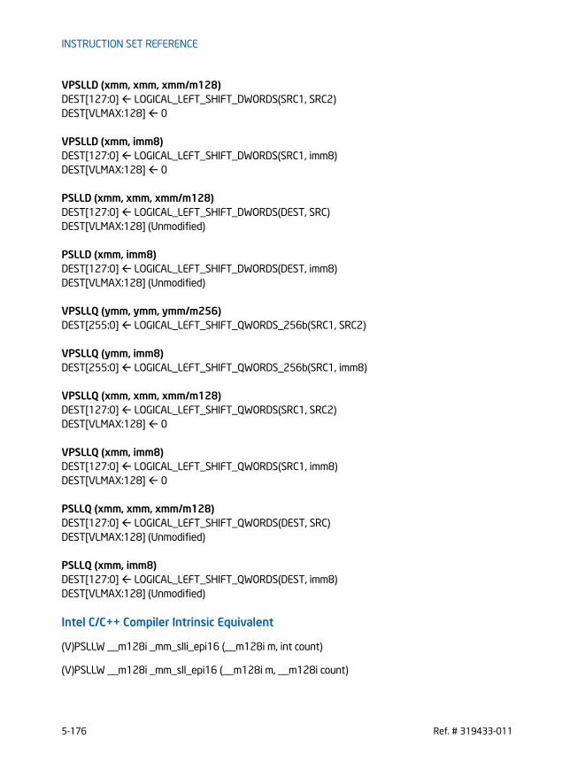
INSTRUCTION SET REFERENCE
VPSLLD (xmm, xmm, xmm/m128)DEST[127:0] LOGICAL_LEFT_SHIFT_DWORDS(SRC1, SRC2)DEST[VLMAX:128] 0
VPSLLD (xmm, imm8)DEST[127:0] LOGICAL_LEFT_SHIFT_DWORDS(SRC1, imm8)DEST[VLMAX:128] 0
PSLLD (xmm, xmm, xmm/m128)DEST[127:0] LOGICAL_LEFT_SHIFT_DWORDS(DEST, SRC)DEST[VLMAX:128] (Unmodified)
PSLLD (xmm, imm8)DEST[127:0] LOGICAL_LEFT_SHIFT_DWORDS(DEST, imm8)DEST[VLMAX:128] (Unmodified)
VPSLLQ (ymm, ymm, ymm/m256)DEST[255:0] LOGICAL_LEFT_SHIFT_QWORDS_256b(SRC1, SRC2)
VPSLLQ (ymm, imm8)DEST[255:0] LOGICAL_LEFT_SHIFT_QWORDS_256b(SRC1, imm8)
VPSLLQ (xmm, xmm, xmm/m128)DEST[127:0] LOGICAL_LEFT_SHIFT_QWORDS(SRC1, SRC2)DEST[VLMAX:128] 0
VPSLLQ (xmm, imm8)DEST[127:0] LOGICAL_LEFT_SHIFT_QWORDS(SRC1, imm8)DEST[VLMAX:128] 0
PSLLQ (xmm, xmm, xmm/m128)DEST[127:0] LOGICAL_LEFT_SHIFT_QWORDS(DEST, SRC)DEST[VLMAX:128] (Unmodified)
PSLLQ (xmm, imm8)DEST[127:0] LOGICAL_LEFT_SHIFT_QWORDS(DEST, imm8)DEST[VLMAX:128] (Unmodified)
Intel C/C++ Compiler Intrinsic Equivalent
(V)PSLLW __m128i _mm_slli_epi16 (__m128i m, int count)
(V)PSLLW __m128i _mm_sll_epi16 (__m128i m, __m128i count)
5-176 Ref. # 319433-011

INSTRUCTION SET REFERENCE
(V)PSLLD __m128i _mm_slli_epi32 (__m128i m, int count)
(V)PSLLD __m128i _mm_sll_epi32 (__m128i m, __m128i count)
(V)PSLLQ __m128i _mm_slli_epi64 (__m128i m, int count)
(V)PSLLQ __m128i _mm_sll_epi64 (__m128i m, __m128i count)
VPSLLW __m256i _mm256_slli_epi16 (__m256i m, int count)
VPSLLW __m256i _mm256_sll_epi16 (__m256i m, __m128i count)
VPSLLD __m256i _mm256_slli_epi32 (__m256i m, int count)
VPSLLD __m256i _mm256_sll_epi32 (__m256i m, __m128i count)
VPSLLQ __m256i _mm256_slli_epi64 (__m256i m, int count)
VPSLLQ __m256i _mm256_sll_epi64 (__m256i m, __m128i count)
SIMD Floating-Point Exceptions
None
Other ExceptionsSame as Exceptions Type 4
Ref. # 319433-011 5-177

INSTRUCTION SET REFERENCE
PSRAW/PSRAD - Bit Shift Arithmetic Right Opcode/Instruction
Op/ En
64/32-bit Mode
CPUID Feature Flag
Description
66 0F E1/r B V/V SSE2 Shift words in xmm1 right by amount specified in xmm2/m128 while shifting in sign bits.
PSRAW xmm1, xmm2/m128
66 0F 71 /4 ib A V/V SSE2 Shift words in xmm1 right by imm8 while shifting in sign bits.PSRAW xmm1, imm8
66 0F E2 /r B V/V SSE2 Shift doublewords in xmm1 right by amount specified in xmm2/m128 while shifting in sign bits.
PSRAD xmm1, xmm2/m128
66 0F 72 /4 ib A V/V SSE2 Shift doublewords in xmm1 right by imm8 while shifting in sign bits.
PSRAD xmm1, imm8
VEX.NDS.128.66.0F.WIG E1 /r D V/V AVX Shift words in xmm2 right by amount specified in xmm3/m128 while shifting in sign bits.
VPSRAW xmm1, xmm2, xmm3/m128
VEX.NDD.128.66.0F.WIG 71 /4 ib C V/V AVX Shift words in xmm2 right by imm8 while shifting in sign bits.VPSRAW xmm1, xmm2, imm8
VEX.NDS.128.66.0F.WIG E2 /r D V/V AVX Shift doublewords in xmm2 right by amount specified in xmm3/m128 while shifting in sign bits.
VPSRAD xmm1, xmm2, xmm3/m128
VEX.NDD.128.66.0F.WIG 72 /4 ib C V/V AVX Shift doublewords in xmm2 right by imm8 while shifting in sign bits.
VPSRAD xmm1, xmm2, imm8
VEX.NDS.256.66.0F.WIG E1 /r D V/V AVX2 Shift words in ymm2 right by amount specified in xmm3/m128 while shifting in sign bits.
VPSRAW ymm1, ymm2, xmm3/m128
5-178 Ref. # 319433-011
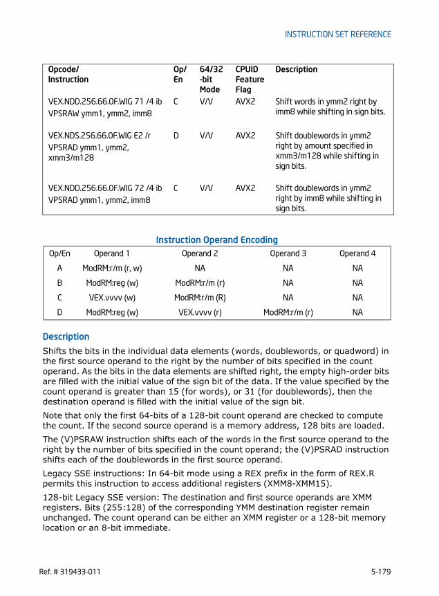
INSTRUCTION SET REFERENCE
Instruction Operand Encoding
Description
Shifts the bits in the individual data elements (words, doublewords, or quadword) in the first source operand to the right by the number of bits specified in the count operand. As the bits in the data elements are shifted right, the empty high-order bits are filled with the initial value of the sign bit of the data. If the value specified by the count operand is greater than 15 (for words), or 31 (for doublewords), then the destination operand is filled with the initial value of the sign bit.Note that only the first 64-bits of a 128-bit count operand are checked to compute the count. If the second source operand is a memory address, 128 bits are loaded.The (V)PSRAW instruction shifts each of the words in the first source operand to the right by the number of bits specified in the count operand; the (V)PSRAD instruction shifts each of the doublewords in the first source operand.Legacy SSE instructions: In 64-bit mode using a REX prefix in the form of REX.R permits this instruction to access additional registers (XMM8-XMM15).128-bit Legacy SSE version: The destination and first source operands are XMM registers. Bits (255:128) of the corresponding YMM destination register remain unchanged. The count operand can be either an XMM register or a 128-bit memory location or an 8-bit immediate.
VEX.NDD.256.66.0F.WIG 71 /4 ib C V/V AVX2 Shift words in ymm2 right by imm8 while shifting in sign bits.VPSRAW ymm1, ymm2, imm8
VEX.NDS.256.66.0F.WIG E2 /r D V/V AVX2 Shift doublewords in ymm2 right by amount specified in xmm3/m128 while shifting in sign bits.
VPSRAD ymm1, ymm2, xmm3/m128
VEX.NDD.256.66.0F.WIG 72 /4 ib C V/V AVX2 Shift doublewords in ymm2 right by imm8 while shifting in sign bits.
VPSRAD ymm1, ymm2, imm8
Op/En Operand 1 Operand 2 Operand 3 Operand 4
A ModRM:r/m (r, w) NA NA NA
B ModRM:reg (w) ModRM:r/m (r) NA NA
C VEX.vvvv (w) ModRM:r/m (R) NA NA
D ModRM:reg (w) VEX.vvvv (r) ModRM:r/m (r) NA
Opcode/Instruction
Op/ En
64/32-bit Mode
CPUID Feature Flag
Description
Ref. # 319433-011 5-179

INSTRUCTION SET REFERENCE
VEX.128 encoded version: The destination and first source operands are XMM regis-ters. Bits (255:128) of the corresponding YMM destination register are zeroed. The count operand can be either an XMM register or a 128-bit memory location or an 8-bit immediate. VEX.256 encoded version: The destination and first source operands are YMM regis-ters. The count operand can be either an XMM register or a 128-bit memory location or an 8-bit immediate.
Operation
ARITHMETIC_RIGHT_SHIFT_WORDS_256b(SRC, COUNT_SRC)COUNT COUNT_SRC[63:0];IF (COUNT > 15)
COUNT 15;FI;DEST[15:0] SignExtend(SRC[15:0] >> COUNT);
(* Repeat shift operation for 2nd through 15th words *)DEST[255:240] SignExtend(SRC[255:240] >> COUNT);
ARITHMETIC_RIGHT_SHIFT_DWORDS_256b(SRC, COUNT_SRC)COUNT COUNT_SRC[63:0];IF (COUNT > 31)
COUNT 31;FI;DEST[31:0] SignExtend(SRC[31:0] >> COUNT);
(* Repeat shift operation for 2nd through 7th words *)DEST[255:224] SignExtend(SRC[255:224] >> COUNT);
ARITHMETIC_RIGHT_SHIFT_WORDS(SRC, COUNT_SRC)COUNT COUNT_SRC[63:0];IF (COUNT > 15)
COUNT 15;FI;DEST[15:0] SignExtend(SRC[15:0] >> COUNT);
(* Repeat shift operation for 2nd through 7th words *)DEST[127:112] SignExtend(SRC[127:112] >> COUNT);
ARITHMETIC_RIGHT_SHIFT_DWORDS(SRC, COUNT_SRC)COUNT COUNT_SRC[63:0];IF (COUNT > 31)
COUNT 31;FI;DEST[31:0] SignExtend(SRC[31:0] >> COUNT);
(* Repeat shift operation for 2nd through 3rd words *)
5-180 Ref. # 319433-011

INSTRUCTION SET REFERENCE
DEST[127:96] SignExtend(SRC[127:96] >> COUNT);
VPSRAW (ymm, ymm, ymm/m256)DEST[255:0] ARITHMETIC_RIGHT_SHIFT_WORDS_256b(SRC1, SRC2)
VPSRAW (ymm, imm8)DEST[255:0] ARITHMETIC_RIGHT_SHIFT_WORDS_256b(SRC1, imm8)
VPSRAW (xmm, xmm, xmm/m128)DEST[127:0] ARITHMETIC_RIGHT_SHIFT_WORDS(SRC1, SRC2)DEST[VLMAX:128] 0
VPSRAW (xmm, imm8)DEST[127:0] ARITHMETIC_RIGHT_SHIFT_WORDS(SRC1, imm8)DEST[VLMAX:128] 0
PSRAW (xmm, xmm, xmm/m128)DEST[127:0] ARITHMETIC_RIGHT_SHIFT_WORDS(DEST, SRC)DEST[VLMAX:128] (Unmodified)
PSRAW (xmm, imm8)DEST[127:0] ARITHMETIC_RIGHT_SHIFT_WORDS(DEST, imm8)DEST[VLMAX:128] (Unmodified)
VPSRAD (ymm, ymm, ymm/m256)DEST[255:0] ARITHMETIC_RIGHT_SHIFT_DWORDS_256b(SRC1, SRC2)
VPSRAD (ymm, imm8)DEST[255:0] ARITHMETIC_RIGHT_SHIFT_DWORDS_256b(SRC1, imm8)
VPSRAD (xmm, xmm, xmm/m128)DEST[127:0] ARITHMETIC_RIGHT_SHIFT_DWORDS(SRC1, SRC2)DEST[VLMAX:128] 0
VPSRAD (xmm, imm8)DEST[127:0] ARITHMETIC_RIGHT_SHIFT_DWORDS(SRC1, imm8)DEST[VLMAX:128] 0
PSRAD (xmm, xmm, xmm/m128)DEST[127:0] ARITHMETIC_RIGHT_SHIFT_DWORDS(DEST, SRC)DEST[VLMAX:128] (Unmodified)
PSRAD (xmm, imm8)
Ref. # 319433-011 5-181

INSTRUCTION SET REFERENCE
DEST[127:0] ARITHMETIC_RIGHT_SHIFT_DWORDS(DEST, imm8)DEST[VLMAX:128] (Unmodified)
Intel C/C++ Compiler Intrinsic Equivalent
(V)PSRAW __m128i _mm_srai_epi16 (__m128i m, int count)
VPSRAW __m256i _mm_srai_epi16 (__m256i m, int count)
(V)PSRAW __m128i _mm_sra_epi16 (__m128i m, __m128i count)
VPSRAW __m256i _mm256_sra_epi16 (__m256i m, __m128i count)
(V)PSRAD __m128i _mm_srai_epi32 (__m128i m, int count)
VPSRAD __m256i _mm_srai_epi32 (__m256i m, int count)
(V)PSRAD __m128i _mm_sra_epi32 (__m128i m, __m128i count)
VPSRAD __m256i _mm256_sra_epi32 (__m256i m, __m128i count)
SIMD Floating-Point Exceptions
None
Other ExceptionsSame as Exceptions Type 4
5-182 Ref. # 319433-011

INSTRUCTION SET REFERENCE
PSRLDQ - Byte Shift Right
Instruction Operand Encoding
Description
Shifts the byte elements within a 128-bit lane of the source operand to the right by the number of bytes specified in the count operand. The empty high-order bytes are cleared (set to all 0s). If the value specified by the count operand is greater than 15, the destination operand is set to all 0s. The source and destination operands are XMM registers. The count operand is an 8-bit immediate.128-bit Legacy SSE version: The source and destination operands are the same. Bits (255:128) of the corresponding YMM destination register remain unchanged.VEX.128 encoded version: Bits (255:128) of the corresponding YMM register are zeroed.VEX.256 encoded version: The source operand is YMM register or a 256-bit memory location. The destination operand is an YMM register. The count operand applies to both the low and high 128-bit lanes.Note: In VEX encoded versions VEX.vvvv encodes the destination register, and VEX.B + ModRM.r/m encodes the source register.
Operation
VPSRLDQ (VEX.256 encoded version)TEMP COUNTIF (TEMP > 15) THEN TEMP 16; FI
Opcode/Instruction
Op/ En
64/32-bit Mode
CPUID Feature Flag
Description
66 0F 73 /3 ib A V/V SSE2 Shift xmm1 right by imm8 bytes while shifting in 0s.PSRLDQ xmm1, imm8
VEX.NDD.128.66.0F.WIG 73 /3 ib B V/V AVX Shift xmm1 right by imm8 bytes while shifting in 0s.VPSRLDQ xmm1, xmm2, imm8
VEX.NDD.256.66.0F.WIG 73 /3 ib B V/V AVX2 Shift ymm1 right by imm8 bytes while shifting in 0s.VPSRLDQ ymm1, ymm2, imm8
Op/En Operand 1 Operand 2 Operand 3 Operand 4
A ModRM:r/m (r, w) NA NA NA
B VEX.vvvv (w) ModRM:r/m (R) NA NA
Ref. # 319433-011 5-183

INSTRUCTION SET REFERENCE
DEST[127:0] SRC[127:0] >> (TEMP * 8)DEST[255:128] SRC[255:128] >> (TEMP * 8)
VPSRLDQ (VEX.128 encoded version)TEMP COUNTIF (TEMP > 15) THEN TEMP 16; FIDEST SRC >> (TEMP * 8)DEST[VLMAX:128] 0
PSRLDQ(128-bit Legacy SSE version)TEMP COUNTIF (TEMP > 15) THEN TEMP 16; FIDEST DEST >> (TEMP * 8)DEST[VLMAX:128] (Unmodified)
Intel C/C++ Compiler Intrinsic Equivalent
(V)PSRLDQ __m128i _mm_srli_si128 ( __m128i a, int imm)
VPSRLDQ __m256i _mm256_srli_si256 ( __m256i a, const int imm)
SIMD Floating-Point Exceptions
None
Other ExceptionsSee Exceptions Type 4
5-184 Ref. # 319433-011

INSTRUCTION SET REFERENCE
PSRLW/PSRLD/PSRLQ - Shift Packed Data Right Logical Opcode/Instruction
Op/ En
64/32-bit Mode
CPUID Feature Flag
Description
66 0F D1 /r B V/V SSE2 Shift words in xmm1 right by amount specified in xmm2/m128 while shifting in 0s.
PSRLW xmm1, xmm2/m128
66 0F 71 /2 ib A V/V SSE2 Shift words in xmm1 right by imm8 while shifting in 0s.PSRLW xmm1, imm8
66 0F D2 /r B V/V SSE2 Shift doublewords in xmm1 right by amount specified in xmm2/m128 while shifting in 0s.
PSRLD xmm1, xmm2/m128
66 0F 72 /2 ib A V/V SSE2 Shift doublewords in xmm1 right by imm8 while shifting in 0s.PSRLD xmm1, imm8
66 0F D3 /r B V/V SSE2 Shift quadwords in xmm1 right by amount specified in xmm2/m128 while shifting in 0s.
PSRLQ xmm1, xmm2/m128
66 0F 73 /2 ib A V/V SSE2 Shift quadwords in xmm1 right by imm8 while shifting in 0s.PSRLQ xmm1, imm8
VEX.NDS.128.66.0F.WIG D1 /r D V/V AVX Shift words in xmm2 right by amount specified in xmm3/m128 while shifting in 0s.
VPSRLW xmm1, xmm2, xmm3/m128
VEX.NDD.128.66.0F.WIG 71 /2 ib C V/V AVX Shift words in xmm2 right by imm8 while shifting in 0s.VPSRLW xmm1, xmm2, imm8
VEX.NDS.128.66.0F.WIG D2 /r D V/V AVX Shift doublewords in xmm2 right by amount specified in xmm3/m128 while shifting in 0s.
VPSRLD xmm1, xmm2, xmm3/m128
VEX.NDD.128.66.0F.WIG 72 /2 ib C V/V AVX Shift doublewords in xmm2 right by imm8 while shifting in 0s.VPSRLD xmm1, xmm2, imm8
Ref. # 319433-011 5-185

INSTRUCTION SET REFERENCE
Instruction Operand Encoding
VEX.NDS.128.66.0F.WIG D3 /r D V/V AVX Shift quadwords in xmm2 right by amount specified in xmm3/m128 while shifting in 0s.
VPSRLQ xmm1, xmm2, xmm3/m128
VEX.NDD.128.66.0F.WIG 73 /2 ib C V/V AVX Shift quadwords in xmm2 right by imm8 while shifting in 0s.VPSRLQ xmm1, xmm2, imm8
VEX.NDS.256.66.0F.WIG D1 /r D V/V AVX2 Shift words in ymm2 right by amount specified in xmm3/m128 while shifting in 0s.
VPSRLW ymm1, ymm2, xmm3/m128
VEX.NDD.256.66.0F.WIG 71 /2 ib C V/V AVX2 Shift words in ymm2 right by imm8 while shifting in 0s.VPSRLW ymm1, ymm2, imm8
VEX.NDS.256.66.0F.WIG D2 /r D V/V AVX2 Shift doublewords in ymm2 right by amount specified in xmm3/m128 while shifting in 0s.
VPSRLD ymm1, ymm2, xmm3/m128
VEX.NDD.256.66.0F.WIG 72 /2 ib C V/V AVX2 Shift doublewords in ymm2 right by imm8 while shifting in 0s.VPSRLD ymm1, ymm2, imm8
VEX.NDS.256.66.0F.WIG D3 /r D V/V AVX2 Shift quadwords in ymm2 right by amount specified in xmm3/m128 while shifting in 0s.
VPSRLQ ymm1, ymm2, xmm3/m128
VEX.NDD.256.66.0F.WIG 73 /2 ib C V/V AVX2 Shift quadwords in ymm2 right by imm8 while shifting in 0s.VPSRLQ ymm1, ymm2, imm8
Op/En Operand 1 Operand 2 Operand 3 Operand 4
A ModRM:r/m (r, w) NA NA NA
B ModRM:reg (w) ModRM:r/m (r) NA NA
C VEX.vvvv (w) ModRM:r/m (R) NA NA
D ModRM:reg (w) VEX.vvvv (r) ModRM:r/m (r) NA
Opcode/Instruction
Op/ En
64/32-bit Mode
CPUID Feature Flag
Description
5-186 Ref. # 319433-011

INSTRUCTION SET REFERENCE
Description
Shifts the bits in the individual data elements (words, doublewords, or quadword) in the first source operand to the right by the number of bits specified in the count operand. As the bits in the data elements are shifted right, the empty high-order bits are cleared (set to 0). If the value specified by the count operand is greater than 15 (for words), 31 (for doublewords), or 63 (for a quadword), then the destination operand is set to all 0s. The destination and first source operands are XMM registers. The count operand can be either an XMM register or a 128-bit memory location or an 8-bit immediate. If the second source operand is a memory address, 128 bits are loaded. Note that only the first 64-bits of a 128-bit count operand are checked to compute the count.The PSRLW instruction shifts each of the words in the first source operand to the right by the number of bits specified in the count operand; the PSRLD instruction shifts each of the doublewords in the first source operand; and the PSRLQ instruction shifts the quadword (or quadwords) in the first source operand.Legacy SSE instructions: In 64-bit mode using a REX prefix in the form of REX.R permits this instruction to access additional registers (XMM8-XMM15).128-bit Legacy SSE version: Bits (255:128) of the corresponding YMM destination register remain unchanged.VEX.128 encoded version: Bits (255:128) of the corresponding YMM register are zeroed.VEX.256 encoded version: The destination and first source operands are YMM regis-ters. The count operand can be either an YMM register or a 128-bit memory location or an 8-bit immediate.Note: In VEX encoded versions of shifts with an immediate count (VEX.128.66.0F 71-73 /2), VEX.vvvv encodes the destination register, and VEX.B + ModRM.r/m encodes the source register.
Operation
LOGICAL_RIGHT_SHIFT_WORDS_256b(SRC, COUNT_SRC)COUNT COUNT_SRC[63:0];IF (COUNT > 15)THEN
DEST[255:0] 0ELSE
DEST[15:0] ZeroExtend(SRC[15:0] >> COUNT);(* Repeat shift operation for 2nd through 15th words *)DEST[255:240] ZeroExtend(SRC[255:240] >> COUNT);
FI;
LOGICAL_RIGHT_SHIFT_WORDS(SRC, COUNT_SRC)COUNT COUNT_SRC[63:0];
Ref. # 319433-011 5-187

INSTRUCTION SET REFERENCE
IF (COUNT > 15)THEN
DEST[127:0] 00000000000000000000000000000000HELSE
DEST[15:0] ZeroExtend(SRC[15:0] >> COUNT);(* Repeat shift operation for 2nd through 7th words *)DEST[127:112] ZeroExtend(SRC[127:112] >> COUNT);
FI;
LOGICAL_RIGHT_SHIFT_DWORDS_256b(SRC, COUNT_SRC)COUNT COUNT_SRC[63:0];IF (COUNT > 31)THEN
DEST[255:0] 0ELSE
DEST[31:0] ZeroExtend(SRC[31:0] >> COUNT);(* Repeat shift operation for 2nd through 3rd words *)DEST[255:224] ZeroExtend(SRC[255:224] >> COUNT);
FI;
LOGICAL_RIGHT_SHIFT_DWORDS(SRC, COUNT_SRC)COUNT COUNT_SRC[63:0];IF (COUNT > 31)THEN
DEST[127:0] 00000000000000000000000000000000HELSE
DEST[31:0] ZeroExtend(SRC[31:0] >> COUNT);(* Repeat shift operation for 2nd through 3rd words *)DEST[127:96] ZeroExtend(SRC[127:96] >> COUNT);
FI;
LOGICAL_RIGHT_SHIFT_QWORDS_256b(SRC, COUNT_SRC)COUNT COUNT_SRC[63:0];IF (COUNT > 63)THEN
DEST[255:0] 0ELSE
DEST[63:0] ZeroExtend(SRC[63:0] >> COUNT);DEST[127:64] ZeroExtend(SRC[127:64] >> COUNT);DEST[191:128] ZeroExtend(SRC[191:128] >> COUNT);DEST[255:192] ZeroExtend(SRC[255:192] >> COUNT);
FI;
5-188 Ref. # 319433-011

INSTRUCTION SET REFERENCE
LOGICAL_RIGHT_SHIFT_QWORDS(SRC, COUNT_SRC)COUNT COUNT_SRC[63:0];IF (COUNT > 63)THEN
DEST[127:0] 00000000000000000000000000000000HELSE
DEST[63:0] ZeroExtend(SRC[63:0] >> COUNT);DEST[127:64] ZeroExtend(SRC[127:64] >> COUNT);
FI;
VPSRLW (ymm, ymm, ymm/m256)DEST[255:0] LOGICAL_RIGHT_SHIFT_WORDS_256b(SRC1, SRC2)
VPSRLW (ymm, imm8)DEST[255:0] LOGICAL_RIGHT_SHIFT_WORDS_256b(SRC1, imm8)
VPSRLW (xmm, xmm, xmm/m128)DEST[127:0] LOGICAL_RIGHT_SHIFT_WORDS(SRC1, SRC2)DEST[VLMAX:128] 0
VPSRLW (xmm, imm8)DEST[127:0] LOGICAL_RIGHT_SHIFT_WORDS(SRC1, imm8)DEST[VLMAX:128] 0
PSRLW (xmm, xmm, xmm/m128)DEST[127:0] LOGICAL_RIGHT_SHIFT_WORDS(DEST, SRC)DEST[VLMAX:128] (Unmodified)
PSRLW (xmm, imm8)DEST[127:0] LOGICAL_RIGHT_SHIFT_WORDS(DEST, imm8)DEST[VLMAX:128] (Unmodified)
VPSRLD (ymm, ymm, ymm/m256)DEST[255:0] LOGICAL_RIGHT_SHIFT_DWORDS_256b(SRC1, SRC2)
VPSRLD (ymm, imm8)DEST[255:0] LOGICAL_RIGHT_SHIFT_DWORDS_256b(SRC1, imm8)
VPSRLD (xmm, xmm, xmm/m128)DEST[127:0] LOGICAL_RIGHT_SHIFT_DWORDS(SRC1, SRC2)DEST[VLMAX:128] 0
VPSRLD (xmm, imm8)
Ref. # 319433-011 5-189

INSTRUCTION SET REFERENCE
DEST[127:0] LOGICAL_RIGHT_SHIFT_DWORDS(SRC1, imm8)DEST[VLMAX:128] 0
PSRLD (xmm, xmm, xmm/m128)DEST[127:0] LOGICAL_RIGHT_SHIFT_DWORDS(DEST, SRC)DEST[VLMAX:128] (Unmodified)
PSRLD (xmm, imm8)DEST[127:0] LOGICAL_RIGHT_SHIFT_DWORDS(DEST, imm8)DEST[VLMAX:128] (Unmodified)
VPSRLQ (ymm, ymm, ymm/m256)DEST[255:0] LOGICAL_RIGHT_SHIFT_QWORDS_256b(SRC1, SRC2)
VPSRLQ (ymm, imm8)DEST[255:0] LOGICAL_RIGHT_SHIFT_QWORDS_256b(SRC1, imm8)
VPSRLQ (xmm, xmm, xmm/m128)DEST[127:0] LOGICAL_RIGHT_SHIFT_QWORDS(SRC1, SRC2)DEST[VLMAX:128] 0
VPSRLQ (xmm, imm8)DEST[127:0] LOGICAL_RIGHT_SHIFT_QWORDS(SRC1, imm8)DEST[VLMAX:128] 0
PSRLQ (xmm, xmm, xmm/m128)DEST[127:0] LOGICAL_RIGHT_SHIFT_QWORDS(DEST, SRC)DEST[VLMAX:128] (Unmodified)
PSRLQ (xmm, imm8)DEST[127:0] LOGICAL_RIGHT_SHIFT_QWORDS(DEST, imm8)DEST[VLMAX:128] (Unmodified)
Intel C/C++ Compiler Intrinsic Equivalent
(V)PSRLW __m128i _mm_srli_epi16 (__m128i m, int count)
VPSRLW __m256i _mm_srli_epi16 (__m256i m, int count)
(V)PSRLW __m128i _mm_srl_epi16 (__m128i m, __m128i count)
VPSRLW __m256i _mm256_srl_epi16 (__m256i m, __m128i count)
(V)PSRLD __m128i _mm_srli_epi32 (__m128i m, int count)
5-190 Ref. # 319433-011

INSTRUCTION SET REFERENCE
VPSRLD __m256i _mm_srli_epi32 (__m256i m, int count)
(V)PSRLD __m128i _mm_srl_epi32 (__m128i m, __m128i count)
VPSRLD __m256i _mm256_srl_epi32 (__m256i m, __m128i count)
(V)PSRLQ __m128i _mm_srli_epi64 (__m128i m, int count)
VPSRLQ __m256i _mm_srli_epi64 (__m256i m, int count)
(V)PSRLQ __m128i _mm_srl_epi64 (__m128i m, __m128i count)
VPSRLQ __m256i _mm256_srl_epi64 (__m256i m, __m128i count)
SIMD Floating-Point Exceptions
None
Other ExceptionsSame as Exceptions Type 4
Ref. # 319433-011 5-191

INSTRUCTION SET REFERENCE
PSUBB/PSUBW/PSUBD/PSUBQ -Packed Integer SubtractOpcode/Instruction
Op/ En
64/32-bit Mode
CPUID Feature Flag
Description
66 0F F8 /r A V/V SSE2 Subtract packed byte integers in xmm2/m128 from xmm1.PSUBB xmm1, xmm2/m128
66 0F F9 /r A V/V SSE2 Subtract packed word integers in xmm2/m128 from xmm1.PSUBW xmm1, xmm2/m128
66 0F FA /r A V/V SSE2 Subtract packed doubleword inte-gers in xmm2/m128 from xmm1.PSUBD xmm1, xmm2/m128
66 0F FB/r A V/V SSE2 Subtract packed quadword inte-gers in xmm2/m128 from xmm1.PSUBQ xmm1, xmm2/m128
VEX.NDS.128.66.0F.WIG F8 /r B V/V AVX Subtract packed byte integers in xmm3/m128 from xmm2.VPSUBB xmm1, xmm2,
xmm3/m128
VEX.NDS.128.66.0F.WIG F9 /r B V/V AVX Subtract packed word integers in xmm3/m128 from xmm2.VPSUBW xmm1, xmm2,
xmm3/m128
VEX.NDS.128.66.0F.WIG FA /r B V/V AVX Subtract packed doubleword inte-gers in xmm3/m128 from xmm2.VPSUBD xmm1, xmm2,
xmm3/m128
VEX.NDS.128.66.0F.WIG FB /r B V/V AVX Subtract packed quadword inte-gers in xmm3/m128 from xmm2.VPSUBQ xmm1, xmm2,
xmm3/m128
VEX.NDS.256.66.0F.WIG F8 /r B V/V AVX2 Subtract packed byte integers in ymm3/m256 from ymm2.VPSUBB ymm1, ymm2,
ymm3/m256
VEX.NDS.256.66.0F.WIG F9 /r B V/V AVX2 Subtract packed word integers in ymm3/m256 from ymm2.VPSUBW ymm1, ymm2,
ymm3/m256
5-192 Ref. # 319433-011

INSTRUCTION SET REFERENCE
Instruction Operand Encoding
Description
Subtracts the packed byte, word, doubleword, or quadword integers in the second source operand from the first source operand and stores the result in the destination operand. When a result is too large to be represented in the 8/16/32/64 integer (overflow), the result is wrapped around and the low bits are written to the destina-tion element (that is, the carry is ignored).Note that these instructions can operate on either unsigned or signed (two’s comple-ment notation) integers; however, it does not set bits in the EFLAGS register to indi-cate overflow and/or a carry. To prevent undetected overflow conditions, software must control the ranges of the values operated on. 128-bit Legacy SSE version: The second source operand is an XMM register or a 128-bit memory location. The first source operand and destination operands are XMM registers. Bits (255:128) of the corresponding YMM destination register remain unchanged.VEX.128 encoded version: The second source operand is an XMM register or a 128-bit memory location. The first source operand and destination operands are XMM registers. Bits (127:128) of the corresponding YMM register are zeroed.VEX.256 encoded version: The second source operand is an YMM register or a 256-bit memory location. The first source operand and destination operands are YMM registers.
Operation
VPSUBB (VEX.256 encoded version)DEST[7:0] SRC1[7:0]-SRC2[7:0]
VEX.NDS.256.66.0F.WIG FA /r B V/V AVX2 Subtract packed doubleword inte-gers in ymm3/m256 from ymm2.VPSUBD ymm1, ymm2,
ymm3/m256
VEX.NDS.256.66.0F.WIG FB /r B V/V AVX2 Subtract packed quadword inte-gers in ymm3/m256 from ymm2.VPSUBQ ymm1, ymm2,
ymm3/m256
Op/En Operand 1 Operand 2 Operand 3 Operand 4
A ModRM:reg (r, w) ModRM:r/m (r) NA NA
B ModRM:reg (w) VEX.vvvv ModRM:r/m (r) NA
Opcode/Instruction
Op/ En
64/32-bit Mode
CPUID Feature Flag
Description
Ref. # 319433-011 5-193

INSTRUCTION SET REFERENCE
DEST[15:8] SRC1[15:8]-SRC2[15:8]DEST[23:16] SRC1[23:16]-SRC2[23:16]DEST[31:24] SRC1[31:24]-SRC2[31:24]DEST[39:32] SRC1[39:32]-SRC2[39:32]DEST[47:40] SRC1[47:40]-SRC2[47:40]DEST[55:48] SRC1[55:48]-SRC2[55:48]DEST[63:56] SRC1[63:56]-SRC2[63:56]DEST[71:64] SRC1[71:64]-SRC2[71:64]DEST[79:72] SRC1[79:72]-SRC2[79:72]DEST[87:80] SRC1[87:80]-SRC2[87:80]DEST[95:88] SRC1[95:88]-SRC2[95:88]DEST[103:96] SRC1[103:96]-SRC2[103:96]DEST[111:104] SRC1[111:104]-SRC2[111:104]DEST[119:112] SRC1[119:112]-SRC2[119:112]DEST[127:120] SRC1[127:120]-SRC2[127:120]DEST[135:128] SRC1[135:128]-SRC2[135:128]DEST[143:136] SRC1[143:136]-SRC2[143:136]DEST[151:144] SRC1[151:144]-SRC2[151:144]DEST[159:152] SRC1[159:152]-SRC2[159:152]DEST[167:160] SRC1[167:160]-SRC2[167:160]DEST[175:168] SRC1[175:168]-SRC2[175:168]DEST[183:176] SRC1[183:176]-SRC2[183:176]DEST[191:184] SRC1[191:184]-SRC2[191:184]DEST[199:192] SRC1[199:192]-SRC2[199:192]DEST[207:200] SRC1[207:200]-SRC2[207:200]DEST[215:208] SRC1[215:208]-SRC2[215:208]DEST[223:216] SRC1[223:216]-SRC2[223:216]DEST[231:224] SRC1[231:224]-SRC2[231:224]DEST[239:232] SRC1[239:232]-SRC2[239:232]DEST[247:240] SRC1[247:240]-SRC2[247:240]DEST[255:248] SRC1[255:248]-SRC2[255:248]
VPSUBB (VEX.128 encoded version)DEST[7:0] SRC1[7:0]-SRC2[7:0]DEST[15:8] SRC1[15:8]-SRC2[15:8]DEST[23:16] SRC1[23:16]-SRC2[23:16]DEST[31:24] SRC1[31:24]-SRC2[31:24]DEST[39:32] SRC1[39:32]-SRC2[39:32]DEST[47:40] SRC1[47:40]-SRC2[47:40]DEST[55:48] SRC1[55:48]-SRC2[55:48]DEST[63:56] SRC1[63:56]-SRC2[63:56]DEST[71:64] SRC1[71:64]-SRC2[71:64]DEST[79:72] SRC1[79:72]-SRC2[79:72]
5-194 Ref. # 319433-011

INSTRUCTION SET REFERENCE
DEST[87:80] SRC1[87:80]-SRC2[87:80]DEST[95:88] SRC1[95:88]-SRC2[95:88]DEST[103:96] SRC1[103:96]-SRC2[103:96]DEST[111:104] SRC1[111:104]-SRC2[111:104]DEST[119:112] SRC1[119:112]-SRC2[119:112]DEST[127:120] SRC1[127:120]-SRC2[127:120]DEST[VLMAX:128] 0
PSUBB (128-bit Legacy SSE version)DEST[7:0] DEST[7:0]-SRC[7:0]DEST[15:8] DEST[15:8]-SRC[15:8]DEST[23:16] DEST[23:16]-SRC[23:16]DEST[31:24] DEST[31:24]-SRC[31:24]DEST[39:32] DEST[39:32]-SRC[39:32]DEST[47:40] DEST[47:40]-SRC[47:40]DEST[55:48] DEST[55:48]-SRC[55:48]DEST[63:56] DEST[63:56]-SRC[63:56]DEST[71:64] DEST[71:64]-SRC[71:64]DEST[79:72] DEST[79:72]-SRC[79:72]DEST[87:80] DEST[87:80]-SRC[87:80]DEST[95:88] DEST[95:88]-SRC[95:88]DEST[103:96] DEST[103:96]-SRC[103:96]DEST[111:104] DEST[111:104]-SRC[111:104]DEST[119:112] DEST[119:112]-SRC[119:112]DEST[127:120] DEST[127:120]-SRC[127:120]DEST[VLMAX:128] (Unmodified)
VPSUBW (VEX.256 encoded version)DEST[15:0] SRC1[15:0]-SRC2[15:0]DEST[31:16] SRC1[31:16]-SRC2[31:16]DEST[47:32] SRC1[47:32]-SRC2[47:32]DEST[63:48] SRC1[63:48]-SRC2[63:48]DEST[79:64] SRC1[79:64]-SRC2[79:64]DEST[95:80] SRC1[95:80]-SRC2[95:80]DEST[111:96] SRC1[111:96]-SRC2[111:96]DEST[127:112] SRC1[127:112]-SRC2[127:112]DEST[143:128] SRC1[143:128]-SRC2[143:128]DEST[159:144] SRC1[159:144]-SRC2[159:144]DEST[175:160] SRC1[175:160]-SRC2[175:160]DEST[191:176] SRC1[191:176]-SRC2[191:176]DEST[207:192] SRC1207:192]-SRC2[207:192]DEST[223:208] SRC1[223:208]-SRC2[223:208]DEST[239:224] SRC1[239:224]-SRC2[239:224]
Ref. # 319433-011 5-195
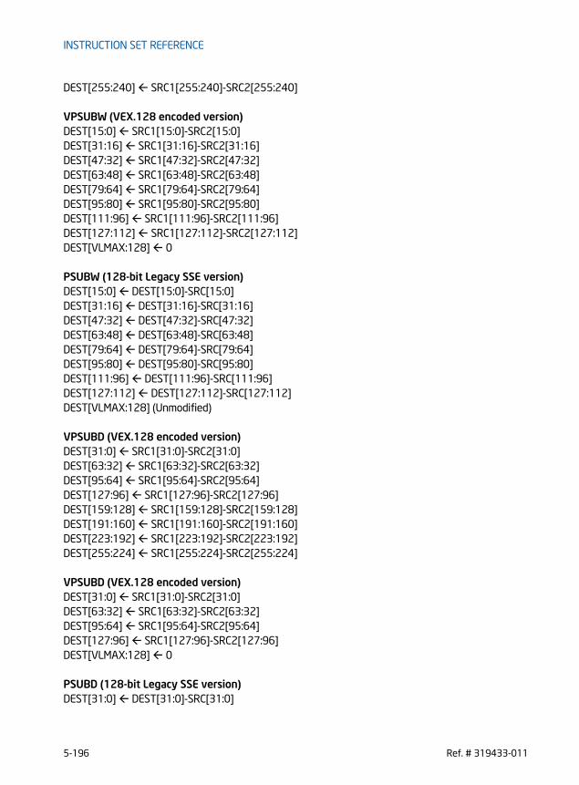
INSTRUCTION SET REFERENCE
DEST[255:240] SRC1[255:240]-SRC2[255:240]
VPSUBW (VEX.128 encoded version)DEST[15:0] SRC1[15:0]-SRC2[15:0]DEST[31:16] SRC1[31:16]-SRC2[31:16]DEST[47:32] SRC1[47:32]-SRC2[47:32]DEST[63:48] SRC1[63:48]-SRC2[63:48]DEST[79:64] SRC1[79:64]-SRC2[79:64]DEST[95:80] SRC1[95:80]-SRC2[95:80]DEST[111:96] SRC1[111:96]-SRC2[111:96]DEST[127:112] SRC1[127:112]-SRC2[127:112]DEST[VLMAX:128] 0
PSUBW (128-bit Legacy SSE version)DEST[15:0] DEST[15:0]-SRC[15:0]DEST[31:16] DEST[31:16]-SRC[31:16]DEST[47:32] DEST[47:32]-SRC[47:32]DEST[63:48] DEST[63:48]-SRC[63:48]DEST[79:64] DEST[79:64]-SRC[79:64]DEST[95:80] DEST[95:80]-SRC[95:80]DEST[111:96] DEST[111:96]-SRC[111:96]DEST[127:112] DEST[127:112]-SRC[127:112]DEST[VLMAX:128] (Unmodified)
VPSUBD (VEX.128 encoded version)DEST[31:0] SRC1[31:0]-SRC2[31:0]DEST[63:32] SRC1[63:32]-SRC2[63:32]DEST[95:64] SRC1[95:64]-SRC2[95:64]DEST[127:96] SRC1[127:96]-SRC2[127:96]DEST[159:128] SRC1[159:128]-SRC2[159:128]DEST[191:160] SRC1[191:160]-SRC2[191:160]DEST[223:192] SRC1[223:192]-SRC2[223:192]DEST[255:224] SRC1[255:224]-SRC2[255:224]
VPSUBD (VEX.128 encoded version)DEST[31:0] SRC1[31:0]-SRC2[31:0]DEST[63:32] SRC1[63:32]-SRC2[63:32]DEST[95:64] SRC1[95:64]-SRC2[95:64]DEST[127:96] SRC1[127:96]-SRC2[127:96]DEST[VLMAX:128] 0
PSUBD (128-bit Legacy SSE version)DEST[31:0] DEST[31:0]-SRC[31:0]
5-196 Ref. # 319433-011
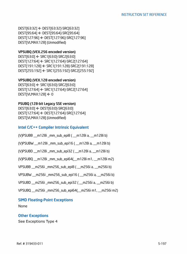
INSTRUCTION SET REFERENCE
DEST[63:32] DEST[63:32]-SRC[63:32]DEST[95:64] DEST[95:64]-SRC[95:64]DEST[127:96] DEST[127:96]-SRC[127:96]DEST[VLMAX:128] (Unmodified)
VPSUBQ (VEX.256 encoded version)DEST[63:0] SRC1[63:0]-SRC2[63:0]DEST[127:64] SRC1[127:64]-SRC2[127:64]DEST[191:128] SRC1[191:128]-SRC2[191:128]DEST[255:192] SRC1[255:192]-SRC2[255:192]
VPSUBQ (VEX.128 encoded version)DEST[63:0] SRC1[63:0]-SRC2[63:0]DEST[127:64] SRC1[127:64]-SRC2[127:64]DEST[VLMAX:128] 0
PSUBQ (128-bit Legacy SSE version)DEST[63:0] DEST[63:0]-SRC[63:0]DEST[127:64] DEST[127:64]-SRC[127:64]DEST[VLMAX:128] (Unmodified)
Intel C/C++ Compiler Intrinsic Equivalent
(V)PSUBB __m128i _mm_sub_epi8 ( __m128i a, __m128i b)
(V)PSUBW __m128i _mm_sub_epi16 ( __m128i a, __m128i b)
(V)PSUBD __m128i _mm_sub_epi32 ( __m128i a, __m128i b)
(V)PSUBQ __m128i _mm_sub_epi64(__m128i m1, __m128i m2)
VPSUBB __m256i _mm256_sub_epi8 ( __m256i a, __m256i b)
VPSUBW __m256i _mm256_sub_epi16 ( __m256i a, __m256i b)
VPSUBD __m256i _mm256_sub_epi32 ( __m256i a, __m256i b)
VPSUBQ __m256i _mm256_sub_epi64(__m256i m1, __m256i m2)
SIMD Floating-Point Exceptions
None
Other ExceptionsSee Exceptions Type 4
Ref. # 319433-011 5-197

INSTRUCTION SET REFERENCE
PSUBSB/PSUBSW -Subtract Packed Signed Integers with Signed Saturation
Instruction Operand Encoding
Opcode/Instruction
Op/ En
64/32-bit Mode
CPUID Feature Flag
Description
66 0F E8 /r A V/V SSE2 Subtract packed signed byte inte-gers in xmm2/m128 from packed signed byte integers in xmm1 and saturate results.
PSUBSB xmm1, xmm2/m128
66 0F E9 /r A V/V SSE2 Subtract packed signed word inte-gers in xmm2/m128 from packed signed word integers in xmm1 and saturate results.
PSUBSW xmm1, xmm2/m128
VEX.NDS.128.66.0F.WIG E8 /r B V/V AVX Subtract packed signed byte inte-gers in xmm3/m128 from packed signed byte integers in xmm2 and saturate results.
VPSUBSB xmm1, xmm2, xmm3/m128
VEX.NDS.128.66.0F.WIG E9 /r B V/V AVX Subtract packed signed word inte-gers in xmm3/m128 from packed signed word integers in xmm2 and saturate results.
VPSUBSW xmm1, xmm2, xmm3/m128
VEX.NDS.256.66.0F.WIG E8 /r B V/V AVX2 Subtract packed signed byte inte-gers in ymm3/m256 from packed signed byte integers in ymm2 and saturate results.
VPSUBSB ymm1, ymm2, ymm3/m256
VEX.NDS.256.66.0F.WIG E9 /r B V/V AVX2 Subtract packed signed word inte-gers in ymm3/m256 from packed signed word integers in ymm2 and saturate results.
VPSUBSW ymm1, ymm2, ymm3/m256
Op/En Operand 1 Operand 2 Operand 3 Operand 4
A ModRM:reg (r, w) ModRM:r/m (r) NA NA
B ModRM:reg (w) VEX.vvvv ModRM:r/m (r) NA
5-198 Ref. # 319433-011
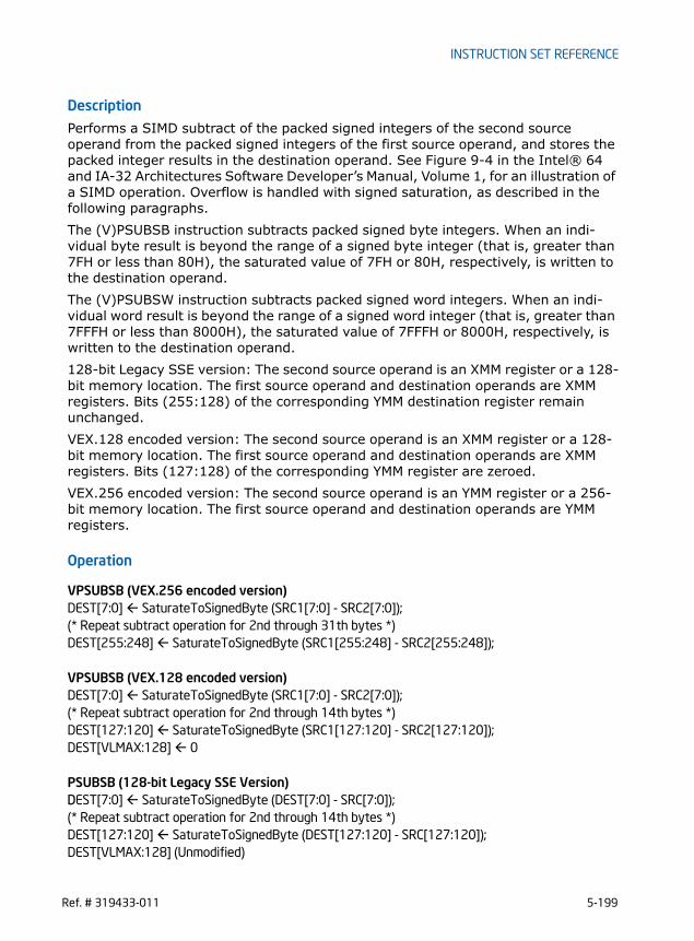
INSTRUCTION SET REFERENCE
Description
Performs a SIMD subtract of the packed signed integers of the second source operand from the packed signed integers of the first source operand, and stores the packed integer results in the destination operand. See Figure 9-4 in the Intel® 64 and IA-32 Architectures Software Developer’s Manual, Volume 1, for an illustration of a SIMD operation. Overflow is handled with signed saturation, as described in the following paragraphs.The (V)PSUBSB instruction subtracts packed signed byte integers. When an indi-vidual byte result is beyond the range of a signed byte integer (that is, greater than 7FH or less than 80H), the saturated value of 7FH or 80H, respectively, is written to the destination operand.The (V)PSUBSW instruction subtracts packed signed word integers. When an indi-vidual word result is beyond the range of a signed word integer (that is, greater than 7FFFH or less than 8000H), the saturated value of 7FFFH or 8000H, respectively, is written to the destination operand.128-bit Legacy SSE version: The second source operand is an XMM register or a 128-bit memory location. The first source operand and destination operands are XMM registers. Bits (255:128) of the corresponding YMM destination register remain unchanged.VEX.128 encoded version: The second source operand is an XMM register or a 128-bit memory location. The first source operand and destination operands are XMM registers. Bits (127:128) of the corresponding YMM register are zeroed.VEX.256 encoded version: The second source operand is an YMM register or a 256-bit memory location. The first source operand and destination operands are YMM registers.
Operation
VPSUBSB (VEX.256 encoded version)DEST[7:0] SaturateToSignedByte (SRC1[7:0] - SRC2[7:0]);(* Repeat subtract operation for 2nd through 31th bytes *)DEST[255:248] SaturateToSignedByte (SRC1[255:248] - SRC2[255:248]);
VPSUBSB (VEX.128 encoded version)DEST[7:0] SaturateToSignedByte (SRC1[7:0] - SRC2[7:0]);(* Repeat subtract operation for 2nd through 14th bytes *)DEST[127:120] SaturateToSignedByte (SRC1[127:120] - SRC2[127:120]);DEST[VLMAX:128] 0
PSUBSB (128-bit Legacy SSE Version)DEST[7:0] SaturateToSignedByte (DEST[7:0] - SRC[7:0]);(* Repeat subtract operation for 2nd through 14th bytes *)DEST[127:120] SaturateToSignedByte (DEST[127:120] - SRC[127:120]);DEST[VLMAX:128] (Unmodified)
Ref. # 319433-011 5-199

INSTRUCTION SET REFERENCE
VPSUBSW (VEX.256 encoded version)DEST[15:0] SaturateToSignedWord (SRC1[15:0] - SRC2[15:0]);(* Repeat subtract operation for 2nd through 15th words *)DEST[255:240] SaturateToSignedWord (SRC1[255:240] - SRC2[255:240]);
VPSUBSW (VEX.128 encoded version)DEST[15:0] SaturateToSignedWord (SRC1[15:0] - SRC2[15:0]);(* Repeat subtract operation for 2nd through 7th words *)DEST[127:112] SaturateToSignedWord (SRC1[127:112] - SRC2[127:112]);DEST[VLMAX:128] 0
PSUBSW (128-bit Legacy SSE Version) DEST[15:0] SaturateToSignedWord (DEST[15:0] - SRC[15:0]);(* Repeat subtract operation for 2nd through 7th words *)DEST[127:112] SaturateToSignedWord (DEST[127:112] - SRC[127:112]);DEST[VLMAX:128] (Unmodified)
Intel C/C++ Compiler Intrinsic Equivalent
(V)PSUBSB __m128i _mm_subs_epi8(__m128i m1, __m128i m2)
(V)PSUBSW __m128i _mm_subs_epi16(__m128i m1, __m128i m2)
VPSUBSB __m256i _mm_subs_epi8(__m256i m1, __m256i m2)
VPSUBSW __m256i _mm_subs_epi16(__m256i m1, __m256i m2)
SIMD Floating-Point Exceptions
None
Other ExceptionsSee Exceptions Type 4
5-200 Ref. # 319433-011

INSTRUCTION SET REFERENCE
PSUBUSB/PSUBUSW -Subtract Packed Unsigned Integers with Unsigned Saturation
Instruction Operand Encoding
Opcode/Instruction
Op/ En
64/32-bit Mode
CPUID Feature Flag
Description
66 0F D8 /r A V/V SSE2 Subtract packed unsigned byte integers in xmm2/m128 from packed unsigned byte integers in xmm1 and saturate result.
PSUBUSB xmm1, xmm2/m128
66 0F D9 /r A V/V SSE2 Subtract packed unsigned word integers in xmm2/m128 from packed unsigned word integers in xmm1 and saturate result.
PSUBUSW xmm1, xmm2/m128
VEX.NDS.128.66.0F.WIG D8 /r B V/V AVX Subtract packed unsigned byte integers in xmm3/m128 from packed unsigned byte integers in xmm2 and saturate result.
VPSUBUSB xmm1, xmm2, xmm3/m128
VEX.NDS.128.66.0F.WIG D9 /r B V/V AVX Subtract packed unsigned word integers in xmm3/m128 from packed unsigned word integers in xmm2 and saturate result.
VPSUBUSW xmm1, xmm2, xmm3/m128
VEX.NDS.256.66.0F.WIG D8 /r B V/V AVX2 Subtract packed unsigned byte integers in ymm3/m256 from packed unsigned byte integers in ymm2 and saturate result.
VPSUBUSB ymm1, ymm2, ymm3/m256
VEX.NDS.256.66.0F.WIG D9 /r B V/V AVX2 Subtract packed unsigned word integers in ymm3/m256 from packed unsigned word integers in ymm2 and saturate result.
VPSUBUSW ymm1, ymm2, ymm3/m256
Op/En Operand 1 Operand 2 Operand 3 Operand 4
A ModRM:reg (r, w) ModRM:r/m (r) NA NA
B ModRM:reg (w) VEX.vvvv ModRM:r/m (r) NA
Ref. # 319433-011 5-201

INSTRUCTION SET REFERENCE
Description
Performs a SIMD subtract of the packed unsigned integers of the second source operand from the packed unsigned integers of the first source operand and stores the packed unsigned integer results in the destination operand. See Figure 9-4 in the Intel® 64 and IA-32 Architectures Software Developer’s Manual, Volume 1, for an illustration of a SIMD operation. Overflow is handled with unsigned saturation, as described in the following paragraphs.The first source and destination operands are XMM registers. The second source operand can be either an XMM register or a 128-bit memory location.The PSUBUSB instruction subtracts packed unsigned byte integers. When an indi-vidual byte result is less than zero, the saturated value of 00H is written to the desti-nation operand.The PSUBUSW instruction subtracts packed unsigned word integers. When an indi-vidual word result is less than zero, the saturated value of 0000H is written to the destination operand.128-bit Legacy SSE version: The second source operand is an XMM register or a 128-bit memory location. The first source operand and destination operands are XMM registers. Bits (255:128) of the corresponding YMM destination register remain unchanged.VEX.128 encoded version: The second source operand is an XMM register or a 128-bit memory location. The first source operand and destination operands are XMM registers. Bits (127:128) of the corresponding YMM register are zeroed.VEX.256 encoded version: The second source operand is an YMM register or a 256-bit memory location. The first source operand and destination operands are YMM registers.
Operation
VPSUBUSB (VEX.256 encoded version)DEST[7:0] SaturateToUnsignedByte (SRC1[7:0] - SRC2[7:0]);(* Repeat subtract operation for 2nd through 31st bytes *)DEST[255:148] SaturateToUnsignedByte (SRC1[255:248] - SRC2[255:248]);
VPSUBUSB (VEX.128 encoded version)DEST[7:0] SaturateToUnsignedByte (SRC1[7:0] - SRC2[7:0]);(* Repeat subtract operation for 2nd through 14th bytes *)DEST[127:120] SaturateToUnsignedByte (SRC1[127:120] - SRC2[127:120]);DEST[VLMAX:128] 0
PSUBUSB (128-bit Legacy SSE Version)DEST[7:0] SaturateToUnsignedByte (DEST[7:0] - SRC[7:0]);(* Repeat subtract operation for 2nd through 14th bytes *)DEST[127:120] SaturateToUnsignedByte (DEST[127:120] - SRC[127:120]);
5-202 Ref. # 319433-011
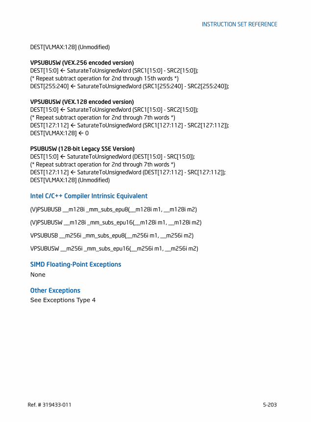
INSTRUCTION SET REFERENCE
DEST[VLMAX:128] (Unmodified)
VPSUBUSW (VEX.256 encoded version)DEST[15:0] SaturateToUnsignedWord (SRC1[15:0] - SRC2[15:0]);(* Repeat subtract operation for 2nd through 15th words *)DEST[255:240] SaturateToUnsignedWord (SRC1[255:240] - SRC2[255:240]);
VPSUBUSW (VEX.128 encoded version)DEST[15:0] SaturateToUnsignedWord (SRC1[15:0] - SRC2[15:0]);(* Repeat subtract operation for 2nd through 7th words *)DEST[127:112] SaturateToUnsignedWord (SRC1[127:112] - SRC2[127:112]);DEST[VLMAX:128] 0
PSUBUSW (128-bit Legacy SSE Version)DEST[15:0] SaturateToUnsignedWord (DEST[15:0] - SRC[15:0]);(* Repeat subtract operation for 2nd through 7th words *)DEST[127:112] SaturateToUnsignedWord (DEST[127:112] - SRC[127:112]);DEST[VLMAX:128] (Unmodified)
Intel C/C++ Compiler Intrinsic Equivalent
(V)PSUBUSB __m128i _mm_subs_epu8(__m128i m1, __m128i m2)
(V)PSUBUSW __m128i _mm_subs_epu16(__m128i m1, __m128i m2)
VPSUBUSB __m256i _mm_subs_epu8(__m256i m1, __m256i m2)
VPSUBUSW __m256i _mm_subs_epu16(__m256i m1, __m256i m2)
SIMD Floating-Point Exceptions
None
Other ExceptionsSee Exceptions Type 4
Ref. # 319433-011 5-203

INSTRUCTION SET REFERENCE
PUNPCKHBW/PUNPCKHWD/PUNPCKHDQ/PUNPCKHQDQ - Unpack High Data
Opcode/Instruction
Op/ En
64/32-bit Mode
CPUID Feature Flag
Description
66 0F 68/r A V/V SSE2 Interleave high-order bytes from xmm1 and xmm2/m128 into xmm1.
PUNPCKHBW xmm1,xmm2/m128
66 0F 69/r A V/V SSE2 Interleave high-order words from xmm1 and xmm2/m128 into xmm1.
PUNPCKHWD xmm1,xmm2/m128
66 0F 6A/r A V/V SSE2 Interleave high-order double-words from xmm1 and xmm2/m128 into xmm1.
PUNPCKHDQ xmm1, xmm2/m128
66 0F 6D/r A V/V SSE2 Interleave high-order quad-word from xmm1 and xmm2/m128 into xmm1 reg-ister.
PUNPCKHQDQ xmm1, xmm2/m128
VEX.NDS.128.66.0F.WIG 68 /r B V/V AVX Interleave high-order bytes from xmm2 and xmm3/m128 into xmm1.
VPUNPCKHBW xmm1,xmm2, xmm3/m128
VEX.NDS.128.66.0F.WIG 69 /r B V/V AVX Interleave high-order words from xmm2 and xmm3/m128 into xmm1.
VPUNPCKHWD xmm1,xmm2, xmm3/m128
VEX.NDS.128.66.0F.WIG 6A /r B V/V AVX Interleave high-order double-words from xmm2 and xmm3/m128 into xmm1.
VPUNPCKHDQ xmm1, xmm2, xmm3/m128
VEX.NDS.128.66.0F.WIG 6D /r B V/V AVX Interleave high-order quad-word from xmm2 and xmm3/m128 into xmm1 reg-ister.
VPUNPCKHQDQ xmm1, xmm2, xmm3/m128
VEX.NDS.256.66.0F.WIG 68 /r B V/V AVX2 Interleave high-order bytes from ymm2 and ymm3/m256 into ymm1 register.
VPUNPCKHBW ymm1, ymm2, ymm3/m256
5-204 Ref. # 319433-011
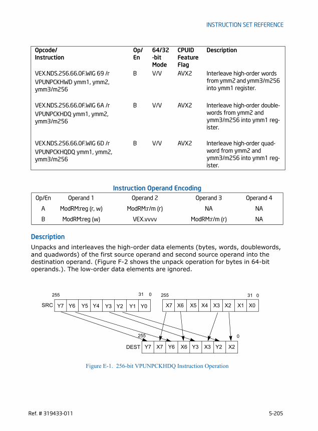
INSTRUCTION SET REFERENCE
Instruction Operand Encoding
Description
Unpacks and interleaves the high-order data elements (bytes, words, doublewords, and quadwords) of the first source operand and second source operand into the destination operand. (Figure F-2 shows the unpack operation for bytes in 64-bit operands.). The low-order data elements are ignored.
Figure E-1. 256-bit VPUNPCKHDQ Instruction Operation
VEX.NDS.256.66.0F.WIG 69 /r B V/V AVX2 Interleave high-order words from ymm2 and ymm3/m256 into ymm1 register.
VPUNPCKHWD ymm1, ymm2, ymm3/m256
VEX.NDS.256.66.0F.WIG 6A /r B V/V AVX2 Interleave high-order double-words from ymm2 and ymm3/m256 into ymm1 reg-ister.
VPUNPCKHDQ ymm1, ymm2, ymm3/m256
VEX.NDS.256.66.0F.WIG 6D /r B V/V AVX2 Interleave high-order quad-word from ymm2 and ymm3/m256 into ymm1 reg-ister.
VPUNPCKHQDQ ymm1, ymm2, ymm3/m256
Op/En Operand 1 Operand 2 Operand 3 Operand 4
A ModRM:reg (r, w) ModRM:r/m (r) NA NA
B ModRM:reg (w) VEX.vvvv ModRM:r/m (r) NA
Opcode/Instruction
Op/ En
64/32-bit Mode
CPUID Feature Flag
Description
X2X7 X6 X3 Y2Y7 Y6 Y3
X0X3 X2 X1Y0Y3 Y2 Y1 X4X7 X6 X5Y4Y7 Y6 Y5SRC
DEST
0255 31
0
0255
255
31
Ref. # 319433-011 5-205
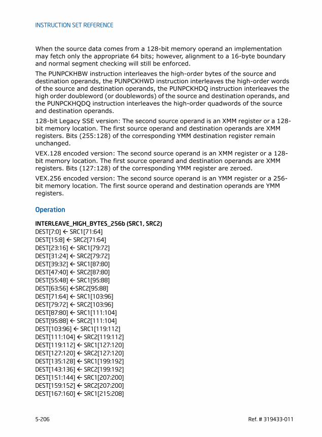
INSTRUCTION SET REFERENCE
When the source data comes from a 128-bit memory operand an implementation may fetch only the appropriate 64 bits; however, alignment to a 16-byte boundary and normal segment checking will still be enforced.The PUNPCKHBW instruction interleaves the high-order bytes of the source and destination operands, the PUNPCKHWD instruction interleaves the high-order words of the source and destination operands, the PUNPCKHDQ instruction interleaves the high order doubleword (or doublewords) of the source and destination operands, and the PUNPCKHQDQ instruction interleaves the high-order quadwords of the source and destination operands.128-bit Legacy SSE version: The second source operand is an XMM register or a 128-bit memory location. The first source operand and destination operands are XMM registers. Bits (255:128) of the corresponding YMM destination register remain unchanged.VEX.128 encoded version: The second source operand is an XMM register or a 128-bit memory location. The first source operand and destination operands are XMM registers. Bits (127:128) of the corresponding YMM register are zeroed.VEX.256 encoded version: The second source operand is an YMM register or a 256-bit memory location. The first source operand and destination operands are YMM registers.
Operation
INTERLEAVE_HIGH_BYTES_256b (SRC1, SRC2) DEST[7:0] SRC1[71:64]DEST[15:8] SRC2[71:64]DEST[23:16] SRC1[79:72]DEST[31:24] SRC2[79:72]DEST[39:32] SRC1[87:80]DEST[47:40] SRC2[87:80]DEST[55:48] SRC1[95:88]DEST[63:56] SRC2[95:88]DEST[71:64] SRC1[103:96]DEST[79:72] SRC2[103:96]DEST[87:80] SRC1[111:104]DEST[95:88] SRC2[111:104]DEST[103:96] SRC1[119:112]DEST[111:104] SRC2[119:112]DEST[119:112] SRC1[127:120]DEST[127:120] SRC2[127:120]DEST[135:128] SRC1[199:192]DEST[143:136] SRC2[199:192]DEST[151:144] SRC1[207:200]DEST[159:152] SRC2[207:200]DEST[167:160] SRC1[215:208]
5-206 Ref. # 319433-011

INSTRUCTION SET REFERENCE
DEST[175:168] SRC2[215:208]DEST[183:176] SRC1[223:216]DEST[191:184] SRC2[223:216]DEST[199:192] SRC1[231:224]DEST[207:200] SRC2[231:224]DEST[215:208] SRC1[239:232]DEST[223:216] SRC2[239:232]DEST[231:224] SRC1[247:240]DEST[239:232] SRC2[247:240]DEST[247:240] SRC1[255:248]DEST[255:248] SRC2[255:248]
INTERLEAVE_HIGH_BYTES (SRC1, SRC2) DEST[7:0] SRC1[71:64]DEST[15:8] SRC2[71:64]DEST[23:16] SRC1[79:72]DEST[31:24] SRC2[79:72]DEST[39:32] SRC1[87:80]DEST[47:40] SRC2[87:80]DEST[55:48] SRC1[95:88]DEST[63:56] SRC2[95:88]DEST[71:64] SRC1[103:96]DEST[79:72] SRC2[103:96]DEST[87:80] SRC1[111:104]DEST[95:88] SRC2[111:104]DEST[103:96] SRC1[119:112]DEST[111:104] SRC2[119:112]DEST[119:112] SRC1[127:120]DEST[127:120] SRC2[127:120]
INTERLEAVE_HIGH_WORDS_256b(SRC1, SRC2)DEST[15:0] SRC1[79:64]DEST[31:16] SRC2[79:64]DEST[47:32] SRC1[95:80]DEST[63:48] SRC2[95:80]DEST[79:64] SRC1[111:96]DEST[95:80] SRC2[111:96]DEST[111:96] SRC1[127:112]DEST[127:112] SRC2[127:112]DEST[143:128] SRC1[207:192]DEST[159:144] SRC2[207:192]DEST[175:160] SRC1[223:208]DEST[191:176] SRC2[223:208]
Ref. # 319433-011 5-207

INSTRUCTION SET REFERENCE
DEST[207:192] SRC1[239:224]DEST[223:208] SRC2[239:224]DEST[239:224] SRC1[255:240]DEST[255:240] SRC2[255:240]
INTERLEAVE_HIGH_WORDS (SRC1, SRC2)DEST[15:0] SRC1[79:64]DEST[31:16] SRC2[79:64]DEST[47:32] SRC1[95:80]DEST[63:48] SRC2[95:80]DEST[79:64] SRC1[111:96]DEST[95:80] SRC2[111:96]DEST[111:96] SRC1[127:112]DEST[127:112] SRC2[127:112]
INTERLEAVE_HIGH_DWORDS_256b(SRC1, SRC2)DEST[31:0] SRC1[95:64]DEST[63:32] SRC2[95:64]DEST[95:64] SRC1[127:96]DEST[127:96] SRC2[127:96]DEST[159:128] SRC1[223:192]DEST[191:160] SRC2[223:192]DEST[223:192] SRC1[255:224]DEST[255:224] SRC2[255:224]
INTERLEAVE_HIGH_DWORDS(SRC1, SRC2)DEST[31:0] SRC1[95:64]DEST[63:32] SRC2[95:64]DEST[95:64] SRC1[127:96]DEST[127:96] SRC2[127:96]
INTERLEAVE_HIGH_QWORDS_256b(SRC1, SRC2)DEST[63:0] SRC1[127:64]DEST[127:64] SRC2[127:64]DEST[191:128] SRC1[255:192]DEST[255:192] SRC2[255:192]
INTERLEAVE_HIGH_QWORDS(SRC1, SRC2)DEST[63:0] SRC1[127:64]DEST[127:64] SRC2[127:64]
PUNPCKHBW (128-bit Legacy SSE Version)DEST[127:0] INTERLEAVE_HIGH_BYTES(DEST, SRC)
5-208 Ref. # 319433-011

INSTRUCTION SET REFERENCE
DEST[255:127] (Unmodified)
VPUNPCKHBW (VEX.128 encoded version)DEST[127:0] INTERLEAVE_HIGH_BYTES(SRC1, SRC2)DEST[255:127] 0
VPUNPCKHBW (VEX.256 encoded version)DEST[255:0] INTERLEAVE_HIGH_BYTES_256b(SRC1, SRC2)
PUNPCKHWD (128-bit Legacy SSE Version)DEST[127:0] INTERLEAVE_HIGH_WORDS(DEST, SRC)DEST[255:127] (Unmodified)
VPUNPCKHWD (VEX.128 encoded version)DEST[127:0] INTERLEAVE_HIGH_WORDS(SRC1, SRC2)DEST[255:127] 0
VPUNPCKHWD (VEX.256 encoded version)DEST[255:0] INTERLEAVE_HIGH_WORDS_256b(SRC1, SRC2)
PUNPCKHDQ (128-bit Legacy SSE Version)DEST[127:0] INTERLEAVE_HIGH_DWORDS(DEST, SRC)DEST[255:127] (Unmodified)
VPUNPCKHDQ (VEX.128 encoded version)DEST[127:0] INTERLEAVE_HIGH_DWORDS(SRC1, SRC2)DEST[255:127] 0
VPUNPCKHDQ (VEX.256 encoded version)DEST[255:0] INTERLEAVE_HIGH_DWORDS_256b(SRC1, SRC2)
PUNPCKHQDQ (128-bit Legacy SSE Version)DEST[127:0] INTERLEAVE_HIGH_QWORDS(DEST, SRC)DEST[255:127] (Unmodified)
VPUNPCKHQDQ (VEX.128 encoded version)DEST[127:0] INTERLEAVE_HIGH_QWORDS(SRC1, SRC2)DEST[255:127] 0
VPUNPCKHQDQ (VEX.256 encoded version)DEST[255:0] INTERLEAVE_HIGH_QWORDS_256(SRC1, SRC2)
Ref. # 319433-011 5-209

INSTRUCTION SET REFERENCE
Intel C/C++ Compiler Intrinsic Equivalent
(V)PUNPCKHBW __m128i _mm_unpackhi_epi8(__m128i m1, __m128i m2)
VPUNPCKHBW __m256i _mm256_unpackhi_epi8(__m256i m1, __m256i m2)
(V)PUNPCKHWD __m128i _mm_unpackhi_epi16(__m128i m1,__m128i m2)
VPUNPCKHWD __m256i _mm256_unpackhi_epi16(__m256i m1,__m256i m2)
(V)PUNPCKHDQ __m128i _mm_unpackhi_epi32(__m128i m1, __m128i m2)
VPUNPCKHDQ __m256i _mm256_unpackhi_epi32(__m256i m1, __m256i m2)
(V)PUNPCKHQDQ __m128i _mm_unpackhi_epi64 ( __m128i a, __m128i b)
VPUNPCKHQDQ __m256i _mm256_unpackhi_epi64 ( __m256i a, __m256i b)
SIMD Floating-Point Exceptions
None
Other ExceptionsSee Exceptions Type 4
5-210 Ref. # 319433-011

INSTRUCTION SET REFERENCE
PUNPCKLBW/PUNPCKLWD/PUNPCKLDQ/PUNPCKLQDQ - Unpack Low Data
Opcode/Instruction
Op/ En
64/32-bit Mode
CPUID Feature Flag
Description
66 0F 60/r A V/V SSE2 Interleave low-order bytes from xmm1 and xmm2/m128 into xmm1.
PUNPCKLBW xmm1,xmm2/m128
66 0F 61/r A V/V SSE2 Interleave low-order words from xmm1 and xmm2/m128 into xmm1.
PUNPCKLWD xmm1,xmm2/m128
66 0F 62/r A V/V SSE2 Interleave low-order double-words from xmm1 and xmm2/m128 into xmm1.
PUNPCKLDQ xmm1, xmm2/m128
66 0F 6C/r A V/V SSE2 Interleave low-order quad-word from xmm1 and xmm2/m128 into xmm1 reg-ister.
PUNPCKLQDQ xmm1, xmm2/m128
VEX.NDS.128.66.0F.WIG 60 /r B V/V AVX Interleave low-order bytes from xmm2 and xmm3/m128 into xmm1.
VPUNPCKLBW xmm1,xmm2, xmm3/m128
VEX.NDS.128.66.0F.WIG 61 /r B V/V AVX Interleave low-order words from xmm2 and xmm3/m128 into xmm1.
VPUNPCKLWD xmm1,xmm2, xmm3/m128
VEX.NDS.128.66.0F.WIG 62 /r B V/V AVX Interleave low-order double-words from xmm2 and xmm3/m128 into xmm1.
VPUNPCKLDQ xmm1, xmm2, xmm3/m128
VEX.NDS.128.66.0F.WIG 6C /r B V/V AVX Interleave low-order quad-word from xmm2 and xmm3/m128 into xmm1 reg-ister.
VPUNPCKLQDQ xmm1, xmm2, xmm3/m128
VEX.NDS.256.66.0F.WIG 60 /r B V/V AVX2 Interleave low-order bytes from ymm2 and ymm3/m256 into ymm1 register.
VPUNPCKLBW ymm1, ymm2, ymm3/m256
Ref. # 319433-011 5-211
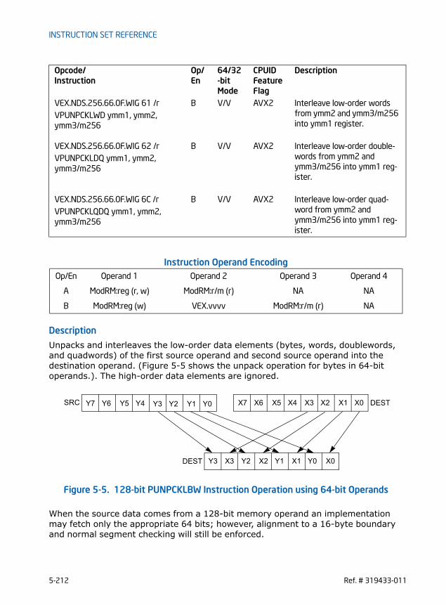
INSTRUCTION SET REFERENCE
Instruction Operand Encoding
Description
Unpacks and interleaves the low-order data elements (bytes, words, doublewords, and quadwords) of the first source operand and second source operand into the destination operand. (Figure 5-5 shows the unpack operation for bytes in 64-bit operands.). The high-order data elements are ignored.
Figure 5-5. 128-bit PUNPCKLBW Instruction Operation using 64-bit Operands
When the source data comes from a 128-bit memory operand an implementation may fetch only the appropriate 64 bits; however, alignment to a 16-byte boundary and normal segment checking will still be enforced.
VEX.NDS.256.66.0F.WIG 61 /r B V/V AVX2 Interleave low-order words from ymm2 and ymm3/m256 into ymm1 register.
VPUNPCKLWD ymm1, ymm2, ymm3/m256
VEX.NDS.256.66.0F.WIG 62 /r B V/V AVX2 Interleave low-order double-words from ymm2 and ymm3/m256 into ymm1 reg-ister.
VPUNPCKLDQ ymm1, ymm2, ymm3/m256
VEX.NDS.256.66.0F.WIG 6C /r B V/V AVX2 Interleave low-order quad-word from ymm2 and ymm3/m256 into ymm1 reg-ister.
VPUNPCKLQDQ ymm1, ymm2, ymm3/m256
Op/En Operand 1 Operand 2 Operand 3 Operand 4
A ModRM:reg (r, w) ModRM:r/m (r) NA NA
B ModRM:reg (w) VEX.vvvv ModRM:r/m (r) NA
Opcode/Instruction
Op/ En
64/32-bit Mode
CPUID Feature Flag
Description
X0X3 X2 X1 Y0Y3 Y2 Y1
X0X3 X2 X1Y0Y3 Y2 Y1 X4X7 X6 X5Y4Y7 Y6 Y5SRC DEST
DEST
5-212 Ref. # 319433-011

INSTRUCTION SET REFERENCE
The PUNPCKLBW instruction interleaves the low-order bytes of the source and desti-nation operands, the PUNPCKLWD instruction interleaves the low-order words of the source and destination operands, the PUNPCKLDQ instruction interleaves the low order doubleword (or doublewords) of the source and destination operands, and the PUNPCKLQDQ instruction interleaves the low-order quadwords of the source and destination operands.Legacy SSE instructions: In 64-bit mode using a REX prefix in the form of REX.R permits this instruction to access additional registers (XMM8-XMM15).128-bit Legacy SSE version: The second source operand is an XMM register or a 128-bit memory location. The first source operand and destination operands are XMM registers. Bits (255:128) of the corresponding YMM destination register remain unchanged.VEX.128 encoded version: The second source operand is an XMM register or a 128-bit memory location. The first source operand and destination operands are XMM registers. Bits (127:128) of the corresponding YMM register are zeroed.VEX.256 encoded version: The second source operand is an YMM register or a 256-bit memory location. The first source operand and destination operands are YMM registers.
Figure E-2. 256-bit VPUNPCKLDQ Instruction Operation
Operation
INTERLEAVE_BYTES_256b (SRC1, SRC2) DEST[7:0] SRC1[7:0]DEST[15:8] SRC2[7:0]DEST[23:16] SRC1[15:8]DEST[31:24] SRC2[15:8]DEST[39:32] SRC1[23:16]DEST[47:40] SRC2[23:16]DEST[55:48] SRC1[31:24]DEST[63:56] SRC2[31:24]
X0X5 X4 X1 Y0Y5 Y4 Y1
X0X3 X2 X1Y0Y3 Y2 Y1 X4X7 X6 X5Y4Y7 Y6 Y5SRC
DEST
0255 31
0
0255
255
31
Ref. # 319433-011 5-213
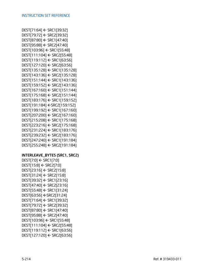
INSTRUCTION SET REFERENCE
DEST[71:64] SRC1[39:32]DEST[79:72] SRC2[39:32]DEST[87:80] SRC1[47:40]DEST[95:88] SRC2[47:40]DEST[103:96] SRC1[55:48]DEST[111:104] SRC2[55:48]DEST[119:112] SRC1[63:56]DEST[127:120] SRC2[63:56]DEST[135:128] SRC1[135:128]DEST[143:136] SRC2[135:128]DEST[151:144] SRC1[143:136]DEST[159:152] SRC2[143:136]DEST[167:160] SRC1[151:144]DEST[175:168] SRC2[151:144]DEST[183:176] SRC1[159:152]DEST[191:184] SRC2[159:152]DEST[199:192] SRC1[167:160]DEST[207:200] SRC2[167:160]DEST[215:208] SRC1[175:168]DEST[223:216] SRC2[175:168]DEST[231:224] SRC1[183:176]DEST[239:232] SRC2[183:176]DEST[247:240] SRC1[191:184]DEST[255:248] SRC2[191:184]
INTERLEAVE_BYTES (SRC1, SRC2) DEST[7:0] SRC1[7:0]DEST[15:8] SRC2[7:0]DEST[23:16] SRC2[15:8]DEST[31:24] SRC2[15:8]DEST[39:32] SRC1[23:16]DEST[47:40] SRC2[23:16]DEST[55:48] SRC1[31:24]DEST[63:56] SRC2[31:24]DEST[71:64] SRC1[39:32]DEST[79:72] SRC2[39:32]DEST[87:80] SRC1[47:40]DEST[95:88] SRC2[47:40]DEST[103:96] SRC1[55:48]DEST[111:104] SRC2[55:48]DEST[119:112] SRC1[63:56]DEST[127:120] SRC2[63:56]
5-214 Ref. # 319433-011
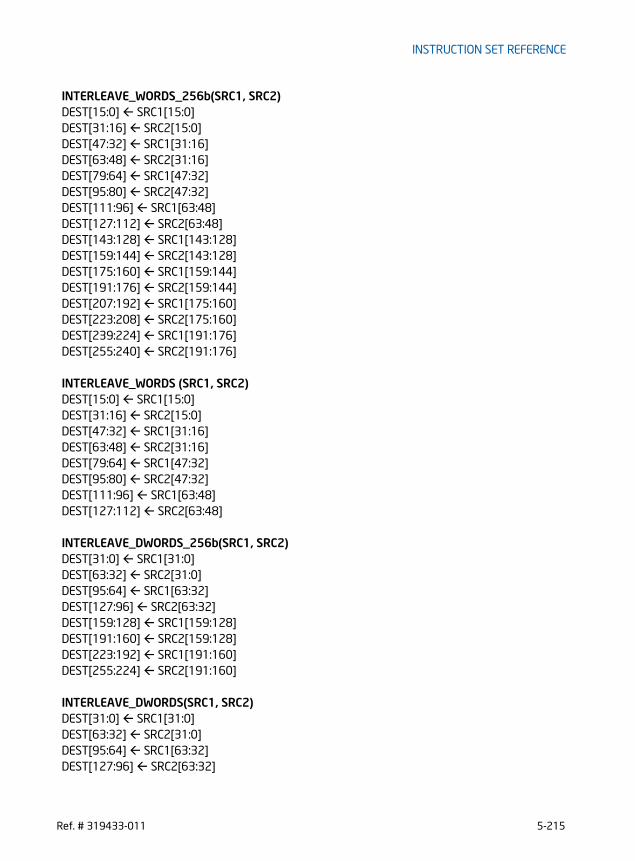
INSTRUCTION SET REFERENCE
INTERLEAVE_WORDS_256b(SRC1, SRC2)DEST[15:0] SRC1[15:0]DEST[31:16] SRC2[15:0]DEST[47:32] SRC1[31:16]DEST[63:48] SRC2[31:16]DEST[79:64] SRC1[47:32]DEST[95:80] SRC2[47:32]DEST[111:96] SRC1[63:48]DEST[127:112] SRC2[63:48]DEST[143:128] SRC1[143:128]DEST[159:144] SRC2[143:128]DEST[175:160] SRC1[159:144]DEST[191:176] SRC2[159:144]DEST[207:192] SRC1[175:160]DEST[223:208] SRC2[175:160]DEST[239:224] SRC1[191:176]DEST[255:240] SRC2[191:176]
INTERLEAVE_WORDS (SRC1, SRC2)DEST[15:0] SRC1[15:0]DEST[31:16] SRC2[15:0]DEST[47:32] SRC1[31:16]DEST[63:48] SRC2[31:16]DEST[79:64] SRC1[47:32]DEST[95:80] SRC2[47:32]DEST[111:96] SRC1[63:48]DEST[127:112] SRC2[63:48]
INTERLEAVE_DWORDS_256b(SRC1, SRC2)DEST[31:0] SRC1[31:0]DEST[63:32] SRC2[31:0]DEST[95:64] SRC1[63:32]DEST[127:96] SRC2[63:32]DEST[159:128] SRC1[159:128]DEST[191:160] SRC2[159:128]DEST[223:192] SRC1[191:160]DEST[255:224] SRC2[191:160]
INTERLEAVE_DWORDS(SRC1, SRC2)DEST[31:0] SRC1[31:0]DEST[63:32] SRC2[31:0]DEST[95:64] SRC1[63:32]DEST[127:96] SRC2[63:32]
Ref. # 319433-011 5-215

INSTRUCTION SET REFERENCE
INTERLEAVE_QWORDS_256b(SRC1, SRC2)DEST[63:0] SRC1[63:0]DEST[127:64] SRC2[63:0]DEST[191:128] SRC1[191:128]DEST[255:192] SRC2[191:128]
INTERLEAVE_QWORDS(SRC1, SRC2)DEST[63:0] SRC1[63:0]DEST[127:64] SRC2[63:0]
PUNPCKLBWDEST[127:0] INTERLEAVE_BYTES(DEST, SRC)DEST[255:127] (Unmodified)
VPUNPCKLBW (VEX.128 encoded instruction)DEST[127:0] INTERLEAVE_BYTES(SRC1, SRC2)DEST[255:127] 0
VPUNPCKLBW (VEX.256 encoded instruction)DEST[255:0] INTERLEAVE_BYTES_128b(SRC1, SRC2)
PUNPCKLWDDEST[127:0] INTERLEAVE_WORDS(DEST, SRC)DEST[255:127] (Unmodified)
VPUNPCKLWD (VEX.128 encoded instruction)DEST[127:0] INTERLEAVE_WORDS(SRC1, SRC2)DEST[255:127] 0
VPUNPCKLWD (VEX.256 encoded instruction)DEST[255:0] INTERLEAVE_WORDS(SRC1, SRC2)
PUNPCKLDQDEST[127:0] INTERLEAVE_DWORDS(DEST, SRC)DEST[255:127] (Unmodified)
VPUNPCKLDQ (VEX.128 encoded instruction)DEST[127:0] INTERLEAVE_DWORDS(SRC1, SRC2)DEST[255:127] 0
VPUNPCKLDQ (VEX.256 encoded instruction)DEST[255:0] INTERLEAVE_DWORDS(SRC1, SRC2)
5-216 Ref. # 319433-011

INSTRUCTION SET REFERENCE
PUNPCKLQDQDEST[127:0] INTERLEAVE_QWORDS(DEST, SRC)DEST[255:127] (Unmodified)
VPUNPCKLQDQ (VEX.128 encoded instruction)DEST[127:0] INTERLEAVE_QWORDS(SRC1, SRC2)DEST[255:127] 0
VPUNPCKLQDQ (VEX.256 encoded instruction)DEST[255:0] INTERLEAVE_QWORDS(SRC1, SRC2)
Intel C/C++ Compiler Intrinsic Equivalent
(V)PUNPCKLBW __m128i _mm_unpacklo_epi8 (__m128i m1, __m128i m2)
VPUNPCKLBW __m256i _mm256_unpacklo_epi8 (__m256i m1, __m256i m2)
(V)PUNPCKLWD __m128i _mm_unpacklo_epi16 (__m128i m1, __m128i m2)
VPUNPCKLWD __m256i _mm256_unpacklo_epi16 (__m256i m1, __m256i m2)
(V)PUNPCKLDQ __m128i _mm_unpacklo_epi32 (__m128i m1, __m128i m2)
VPUNPCKLDQ __m256i _mm256_unpacklo_epi32 (__m256i m1, __m256i m2)
(V)PUNPCKLQDQ __m128i _mm_unpacklo_epi64 (__m128i m1, __m128i m2)
VPUNPCKLQDQ __m256i _mm256_unpacklo_epi64 (__m256i m1, __m256i m2)
SIMD Floating-Point Exceptions
None
Other ExceptionsSee Exceptions Type 4
Ref. # 319433-011 5-217

INSTRUCTION SET REFERENCE
PXOR - Exclusive Or
Instruction Operand Encoding
Description
Performs a bitwise logical XOR operation on the second source operand and the first source operand and stores the result in the destination operand. Each bit of the result is set to 1 if the corresponding bits of the first and second operands differ, otherwise it is set to 0.Legacy SSE instructions: In 64-bit mode using a REX prefix in the form of REX.R permits this instruction to access additional registers (XMM8-XMM15).128-bit Legacy SSE version: The second source operand is an XMM register or a 128-bit memory location. The first source operand and destination operands are XMM registers. Bits (255:128) of the corresponding YMM destination register remain unchanged.VEX.128 encoded version: The second source operand is an XMM register or a 128-bit memory location. The first source operand and destination operands are XMM registers. Bits (127:128) of the corresponding YMM register are zeroed.VEX.256 encoded version: The second source operand is an YMM register or a 256-bit memory location. The first source operand and destination operands are YMM registers.
Operation
VPXOR (VEX.256 encoded version)DEST SRC1 XOR SRC2
Opcode/Instruction
Op/ En
64/32-bit Mode
CPUID Feature Flag
Description
66 0F EF /r A V/V SSE2 Bitwise XOR of xmm2/m128 and xmm1.PXOR xmm1, xmm2/m128
VEX.NDS.128.66.0F.WIG EF /r B V/V AVX Bitwise XOR of xmm3/m128 and xmm2.VPXOR xmm1, xmm2, xmm3/m128
VEX.NDS.256.66.0F.WIG EF /r B V/V AVX2 Bitwise XOR of ymm3/m256 and ymm2.VPXOR ymm1, ymm2, ymm3/m256
Op/En Operand 1 Operand 2 Operand 3 Operand 4
A ModRM:reg (r, w) ModRM:r/m (r) NA NA
B ModRM:reg (w) VEX.vvvv ModRM:r/m (r) NA
5-218 Ref. # 319433-011
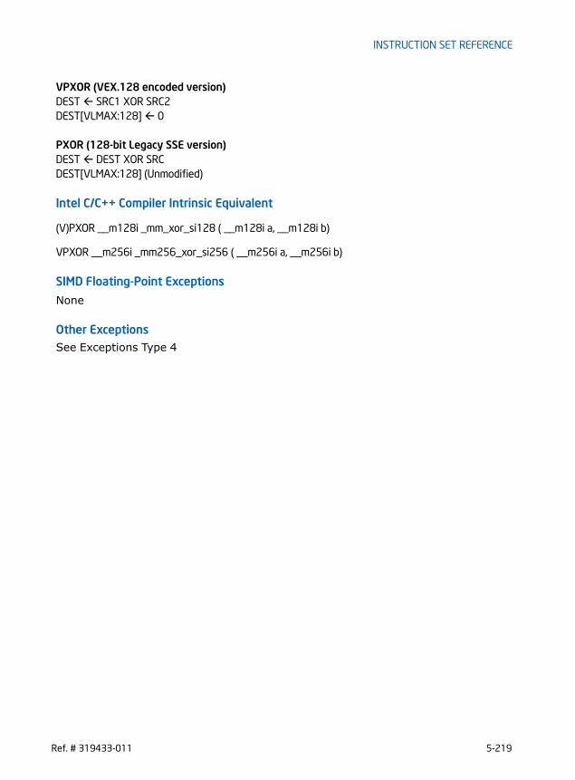
INSTRUCTION SET REFERENCE
VPXOR (VEX.128 encoded version)DEST SRC1 XOR SRC2DEST[VLMAX:128] 0
PXOR (128-bit Legacy SSE version)DEST DEST XOR SRCDEST[VLMAX:128] (Unmodified)
Intel C/C++ Compiler Intrinsic Equivalent
(V)PXOR __m128i _mm_xor_si128 ( __m128i a, __m128i b)
VPXOR __m256i _mm256_xor_si256 ( __m256i a, __m256i b)
SIMD Floating-Point Exceptions
None
Other ExceptionsSee Exceptions Type 4
Ref. # 319433-011 5-219
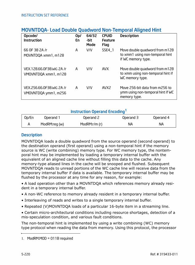
INSTRUCTION SET REFERENCE
MOVNTDQA- Load Double Quadword Non-Temporal Aligned Hint
Instruction Operand Encoding1
Description
MOVNTDQA loads a double quadword from the source operand (second operand) to the destination operand (first operand) using a non-temporal hint if the memory source is WC (write combining) memory type. For WC memory type, the nontem-poral hint may be implemented by loading a temporary internal buffer with the equivalent of an aligned cache line without filling this data to the cache. Any memory-type aliased lines in the cache will be snooped and flushed. Subsequent MOVNTDQA reads to unread portions of the WC cache line will receive data from the temporary internal buffer if data is available. The temporary internal buffer may be flushed by the processor at any time for any reason, for example:• A load operation other than a MOVNTDQA which references memory already resi-dent in a temporary internal buffer.• A non-WC reference to memory already resident in a temporary internal buffer.• Interleaving of reads and writes to a single temporary internal buffer.• Repeated (V)MOVNTDQA loads of a particular 16-byte item in a streaming line.• Certain micro-architectural conditions including resource shortages, detection of a mis-speculation condition, and various fault conditions.The non-temporal hint is implemented by using a write combining (WC) memory type protocol when reading the data from memory. Using this protocol, the processor
Opcode/Instruction
Op/ En
64/32-bit Mode
CPUID Feature Flag
Description
66 0F 38 2A /r A V/V SSE4_1 Move double quadword from m128 to xmm1 using non-temporal hint if WC memory type.
MOVNTDQA xmm1, m128
VEX.128.66.0F38.WIG 2A /r A V/V AVX Move double quadword from m128 to xmm using non-temporal hint if WC memory type.
VMOVNTDQA xmm1, m128
VEX.256.66.0F38.WIG 2A /r A V/V AVX2 Move 256-bit data from m256 to ymm using non-temporal hint if WC memory type.
VMOVNTDQA ymm1, m256
Op/En Operand 1 Operand 2 Operand 3 Operand 4
A ModRM:reg (w) ModRM:r/m (r) NA NA
1. ModRM.MOD = 011B required
5-220 Ref. # 319433-011

INSTRUCTION SET REFERENCE
does not read the data into the cache hierarchy, nor does it fetch the corresponding cache line from memory into the cache hierarchy. The memory type of the region being read can override the non-temporal hint, if the memory address specified for the non-temporal read is not a WC memory region. Information on non-temporal reads and writes can be found in “Caching of Temporal vs. Non-Temporal Data” in Chapter 10 in the Intel® 64 and IA-32 Architecture Software Developer’s Manual, Volume 3A.Because the WC protocol uses a weakly-ordered memory consistency model, a fencing operation implemented with a MFENCE instruction should be used in conjunc-tion with MOVNTDQA instructions if multiple processors might use different memory types for the referenced memory locations or to synchronize reads of a processor with writes by other agents in the system. A processor’s implementation of the streaming load hint does not override the effective memory type, but the implemen-tation of the hint is processor dependent. For example, a processor implementation may choose to ignore the hint and process the instruction as a normal MOVDQA for any memory type. Alternatively, another implementation may optimize cache reads generated by MOVNTDQA on WB memory type to reduce cache evictions.The 128-bit (V)MOVNTDQA addresses must be 16-byte aligned or the instruction will cause a #GP.The 256-bit VMOVNTDQA addresses must be 32-byte aligned or the instruction will cause a #GP.
Operation
MOVNTDQA (128bit- Legacy SSE form)DEST SRCDEST[VLMAX:128] (Unmodified)
VMOVNTDQA (VEX.128 encoded form)DEST SRCDEST[VLMAX:128] 0
VMOVNTDQA (VEX.256 encoded form)DEST[255:0] SRC[255:0]
Intel C/C++ Compiler Intrinsic Equivalent
(V)MOVNTDQA __m128i _mm_stream_load_si128 (__m128i *p);
VMOVNTDQA __m256i _mm256_stream_load_si256 (const __m256i *p);
SIMD Floating-Point Exceptions
None
Ref. # 319433-011 5-221

INSTRUCTION SET REFERENCE
Other ExceptionsSee Exceptions Type1; additionally#UD If VEX.vvvv != 1111B.
5-222 Ref. # 319433-011

INSTRUCTION SET REFERENCE
VBROADCAST- Broadcast Floating-Point Data
Instruction Operand Encoding
Description
Take the low floating-point data element from the source operand (second operand) and broadcast to all elements of the destination operand (first operand).The destination operand is a YMM register. The source operand is an XMM register, only the low 32-bit or 64-bit data element is used. Note: In VEX-encoded versions, VEX.vvvv is reserved and must be 1111b otherwise instructions will #UD.
Opcode/Instruction
Op/ En
64/32-bit Mode
CPUID Feature Flag
Description
VEX.128.66.0F38.W0 18 /r A V/V AVX Broadcast single-precision floating-point element in mem to four loca-tions in xmm1.
VBROADCASTSS xmm1, m32
VEX.256.66.0F38.W0 18 /r A V/V AVX Broadcast single-precision floating-point element in mem to eight loca-tions in ymm1.
VBROADCASTSS ymm1, m32
VEX.256.66.0F38.W0 19 /r A V/V AVX Broadcast double-precision float-ing-point element in mem to four locations in ymm1.
VBROADCASTSD ymm1, m64
VEX.128.66.0F38.W0 18/r A V/V AVX2 Broadcast the low single-precision floating-point element in the source operand to four locations in xmm1.
VBROADCASTSS xmm1, xmm2
VEX.256.66.0F38.W0 18 /r A V/V AVX2 Broadcast low single-precision floating-point element in the source operand to eight locations in ymm1.
VBROADCASTSS ymm1, xmm2
VEX.256.66.0F38.W0 19 /r A V/V AVX2 Broadcast low double-precision floating-point element in the source operand to four locations in ymm1.
VBROADCASTSD ymm1, xmm2
Op/En Operand 1 Operand 2 Operand 3 Operand 4
A ModRM:reg (w) ModRM:r/m (r) NA NA
Ref. # 319433-011 5-223

INSTRUCTION SET REFERENCE
An attempt to execute VBROADCASTSD encoded with VEX.L= 0 will cause an #UD exception.
Operation
VBROADCASTSS (128 bit version)temp SRC[31:0]FOR j 0 TO 3DEST[31+j*32: j*32] tempENDFORDEST[VLMAX:128] 0
VBROADCASTSS (VEX.256 encoded version)temp SRC[31:0]FOR j 0 TO 7DEST[31+j*32: j*32] tempENDFOR
VBROADCASTSD (VEX.256 encoded version)temp SRC[63:0]DEST[63:0] tempDEST[127:64] tempDEST[191:128] tempDEST[255:192] temp
Intel C/C++ Compiler Intrinsic Equivalent
VBROADCASTSS __m128 _mm_broadcastss_ps(__m128 );
VBROADCASTSS __m256 _mm256_broadcastss_ps(__m128);
VBROADCASTSD __m256d _mm256_broadcastsd_pd(__m128d);
SIMD Floating-Point Exceptions
None
Other ExceptionsSee Exceptions Type 6; additionally#UD If VEX.L = 0 for VBROADCASTSD,
If VEX.W = 1.
5-224 Ref. # 319433-011
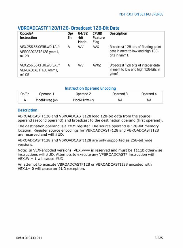
INSTRUCTION SET REFERENCE
VBROADCASTF128/I128- Broadcast 128-Bit Data
Instruction Operand Encoding
Description
VBROADCASTF128 and VBROADCASTI128 load 128-bit data from the source operand (second operand) and broadcast to the destination operand (first operand).The destination operand is a YMM register. The source operand is 128-bit memory location. Register source encodings for VBROADCASTF128 and VBROADCASTI128 are reserved and will #UD.VBROADCASTF128 and VBROADCASTI128 are only supported as 256-bit wide versions. Note: In VEX-encoded versions, VEX.vvvv is reserved and must be 1111b otherwise instructions will #UD. Attempts to execute any VPBROADCAST* instruction with VEX.W = 1 will cause #UD.An attempt to execute VBROADCASTF128 or VBROADCASTI128 encoded with VEX.L= 0 will cause an #UD exception.
Opcode/Instruction
Op/ En
64/32-bit Mode
CPUID Feature Flag
Description
VEX.256.66.0F38.W0 1A /r A V/V AVX Broadcast 128 bits of floating-point data in mem to low and high 128-bits in ymm1.
VBROADCASTF128 ymm1, m128
VEX.256.66.0F38.W0 5A /r A V/V AVX2 Broadcast 128 bits of integer data in mem to low and high 128-bits in ymm1.
VBROADCASTI128 ymm1, m128
Op/En Operand 1 Operand 2 Operand 3 Operand 4
A ModRM:reg (w) ModRM:r/m (r) NA NA
Ref. # 319433-011 5-225

INSTRUCTION SET REFERENCE
Figure 5-6. VBROADCASTI128 Operation
Operation
VBROADCASTF128/VBROADCASTI128temp SRC[127:0]DEST[127:0] tempDEST[255:128] temp
Intel C/C++ Compiler Intrinsic Equivalent
VBROADCASTF128 __m256 _mm_broadcast_ps(__m128 );
VBROADCASTF128 __m256d _mm_broadcast_pd(__m128d );
VBROADCASTI128 __m256i _mm_broadcastsi128_si256(__m128i );
SIMD Floating-Point Exceptions
None
Other ExceptionsSee Exceptions Type 6; additionally#UD If VEX.L = 0 ,
If VEX.W = 1.
DEST
m128i X0
X0X0
5-226 Ref. # 319433-011

INSTRUCTION SET REFERENCE
VPBLENDD - Blend Packed Dwords
Instruction Operand Encoding
Description
Dword elements from the source operand (second operand) are conditionally written to the destination operand (first operand) depending on bits in the immediate operand (third operand). The immediate bits (bits 7:0) form a mask that determines whether the corresponding word in the destination is copied from the source. If a bit in the mask, corresponding to a word, is “1", then the word is copied, else the word is unchanged.VEX.128 encoded version: The second source operand can be an XMM register or a 128-bit memory location. The first source and destination operands are XMM regis-ters. Bits (255:128) of the corresponding YMM register are zeroed.VEX.256 encoded version: The first source operand is a YMM register. The second source operand is a YMM register or a 256-bit memory location. The destination operand is a YMM register.
Operation
VPBLENDD (VEX.256 encoded version)IF (imm8[0] == 1) THEN DEST[31:0] SRC2[31:0]ELSE DEST[31:0] SRC1[31:0]IF (imm8[1] == 1) THEN DEST[63:32] SRC2[63:32]ELSE DEST[63:32] SRC1[63:32]IF (imm8[2] == 1) THEN DEST[95:64] SRC2[95:64]ELSE DEST[95:64] SRC1[95:64]IF (imm8[3] == 1) THEN DEST[127:96] SRC2[127:96]
Opcode/Instruction
Op/ En
64/32-bit Mode
CPUID Feature Flag
Description
VEX.NDS.128.66.0F3A.W0 02 /r ib A V/V AVX2 Select dwords from xmm2 and xmm3/m128 from mask specified in imm8 and store the values into xmm1.
VPBLENDD xmm1, xmm2, xmm3/m128, imm8
VEX.NDS.256.66.0F3A.W0 02 /r ib A V/V AVX2 Select dwords from ymm2 and ymm3/m256 from mask specified in imm8 and store the values into ymm1.
VPBLENDD ymm1, ymm2, ymm3/m256, imm8
Op/En Operand 1 Operand 2 Operand 3 Operand 4
A ModRM:reg (w) VEX.vvvv ModRM:r/m (r) NA
Ref. # 319433-011 5-227

INSTRUCTION SET REFERENCE
ELSE DEST[127:96] SRC1[127:96]IF (imm8[4] == 1) THEN DEST[159:128] SRC2[159:128]ELSE DEST[159:128] SRC1[159:128]IF (imm8[5] == 1) THEN DEST[191:160] SRC2[191:160]ELSE DEST[191:160] SRC1[191:160]IF (imm8[6] == 1) THEN DEST[223:192] SRC2[223:192]ELSE DEST[223:192] SRC1[223:192]IF (imm8[7] == 1) THEN DEST[255:224] SRC2[255:224]ELSE DEST[255:224] SRC1[255:224]
VPBLENDD (VEX.128 encoded version)IF (imm8[0] == 1) THEN DEST[31:0] SRC2[31:0]ELSE DEST[31:0] SRC1[31:0]IF (imm8[1] == 1) THEN DEST[63:32] SRC2[63:32]ELSE DEST[63:32] SRC1[63:32]IF (imm8[2] == 1) THEN DEST[95:64] SRC2[95:64]ELSE DEST[95:64] SRC1[95:64]IF (imm8[3] == 1) THEN DEST[127:96] SRC2[127:96]ELSE DEST[127:96] SRC1[127:96]DEST[VLMAX:128] 0
Intel C/C++ Compiler Intrinsic Equivalent
VPBLENDD __m128i _mm_blend_epi32 (__m128i v1, __m128i v2, const int mask)
VPBLENDD __m256i _mm256_blend_epi32 (__m256i v1, __m256i v2, const int mask)
SIMD Floating-Point Exceptions
None
Other ExceptionsSee Exceptions Type 4; additionally#UD If VEX.W = 1.
5-228 Ref. # 319433-011

INSTRUCTION SET REFERENCE
VPBROADCAST- Broadcast Integer Data
Instruction Operand Encoding
Description
Load integer data from the source operand (second operand) and broadcast to all elements of the destination operand (first operand).
Opcode/Instruction
Op/ En
64/32-bit Mode
CPUID Feature Flag
Description
VEX.128.66.0F38.W0 78 /r A V/V AVX2 Broadcast a byte integer in the source operand to sixteen locations in xmm1.
VPBROADCASTB xmm1, xmm2/m8
VEX.256.66.0F38.W0 78 /r A V/V AVX2 Broadcast a byte integer in the source operand to thirty-two loca-tions in ymm1.
VPBROADCASTB ymm1, xmm2/m8
VEX.128.66.0F38.W0 79 /r A V/V AVX2 Broadcast a word integer in the source operand to eight locations in xmm1.
VPBROADCASTW xmm1, xmm2/m16
VEX.256.66.0F38.W0 79 /r A V/V AVX2 Broadcast a word integer in the source operand to sixteen locations in ymm1.
VPBROADCASTW ymm1, xmm2/m16
VEX.128.66.0F38.W0 58 /r A V/V AVX2 Broadcast a dword integer in the source operand to four locations in xmm1.
VPBROADCASTD xmm1, xmm2/m32
VEX.256.66.0F38.W0 58 /r A V/V AVX2 Broadcast a dword integer in the source operand to eight locations in ymm1.
VPBROADCASTD ymm1, xmm2/m32
VEX.128.66.0F38.W0 59 /r A V/V AVX2 Broadcast a qword element in mem to two locations in xmm1.VPBROADCASTQ xmm1,
xmm2/m64VEX.256.66.0F38.W0 59 /r A V/V AVX2 Broadcast a qword element in mem
to four locations in ymm1.VPBROADCASTQ ymm1, xmm2/m64
Op/En Operand 1 Operand 2 Operand 3 Operand 4
A ModRM:reg (w) ModRM:r/m (r) NA NA
Ref. # 319433-011 5-229

INSTRUCTION SET REFERENCE
The destination operand is a YMM register. The source operand is 8-bit, 16-bit 32-bit, 64-bit memory location or the low 8-bit, 16-bit 32-bit, 64-bit data in an XMM register. VPBROADCASTB/D/W/Q also support XMM register as the source operand. VPBROADCASTB/W/D/Q is supported in both 128-bit and 256-bit wide versions. Note: In VEX-encoded versions, VEX.vvvv is reserved and must be 1111b otherwise instructions will #UD. Attempts to execute any VPBROADCAST* instruction with VEX.W = 1 will cause #UD.
Figure 5-7. VPBROADCASTD Operation (VEX.256 encoded version)
Figure 5-8. VPBROADCASTD Operation (128-bit version)
DEST
m32 X0
X0X0 X0X0 X0X0 X0X0
DEST
m32 X0
X0X0 X00 X00 00
5-230 Ref. # 319433-011

INSTRUCTION SET REFERENCE
Operation
VPBROADCASTB (VEX.128 encoded version)temp SRC[7:0]FOR j 0 TO 15DEST[7+j*8: j*8] tempENDFORDEST[VLMAX:128] 0
VPBROADCASTB (VEX.256 encoded version)temp SRC[7:0]FOR j 0 TO 31DEST[7+j*8: j*8] tempENDFOR
VPBROADCASTW (VEX.128 encoded version)temp SRC[15:0]FOR j 0 TO 7DEST[15+j*16: j*16] tempENDFORDEST[VLMAX:128] 0
VPBROADCASTW (VEX.256 encoded version)temp SRC[15:0]FOR j 0 TO 15DEST[15+j*16: j*16] tempENDFOR
DEST
m64 X0
X0X0X0X0
Ref. # 319433-011 5-231

INSTRUCTION SET REFERENCE
VPBROADCASTD (128 bit version)temp SRC[31:0]FOR j 0 TO 3DEST[31+j*32: j*32] tempENDFORDEST[VLMAX:128] 0
VPBROADCASTD (VEX.256 encoded version)temp SRC[31:0]FOR j 0 TO 7DEST[31+j*32: j*32] tempENDFOR
VPBROADCASTQ (VEX.128 encoded version)temp SRC[63:0]DEST[63:0] tempDEST[127:64] tempDEST[VLMAX:128] 0
VPBROADCASTQ (VEX.256 encoded version)temp SRC[63:0]DEST[63:0] tempDEST[127:64] tempDEST[191:128] tempDEST[255:192] temp
Intel C/C++ Compiler Intrinsic Equivalent
VPBROADCASTB __m256i _mm256_broadcastb_epi8(__m128i );
VPBROADCASTW __m256i _mm256_broadcastw_epi16(__m128i );
VPBROADCASTD __m256i _mm256_broadcastd_epi32(__m128i );
VPBROADCASTQ __m256i _mm256_broadcastq_epi64(__m128i );
VPBROADCASTB __m128i _mm_broadcastb_epi8(__m128i );
VPBROADCASTW __m128i _mm_broadcastw_epi16(__m128i );
VPBROADCASTD __m128i _mm_broadcastd_epi32(__m128i );
VPBROADCASTQ __m128i _mm_broadcastq_epi64(__m128i );
SIMD Floating-Point Exceptions
None
5-232 Ref. # 319433-011
INSTRUCTION SET REFERENCE
Other ExceptionsSee Exceptions Type 6; additionally#UD If VEX.W = 1.
Ref. # 319433-011 5-233

INSTRUCTION SET REFERENCE
VPERMD - Full Doublewords Element Permutation
Instruction Operand Encoding
Description
Use the index values in each dword element of the first source operand (the second operand) to select a dword element in the second source operand (the third operand), the resultant dword value from the second source operand is copied to the destination operand (the first operand) in the corresponding position of the index element. Note that this instruction permits a doubleword in the source operand to be copied to more than one doubleword location in the destination operand.An attempt to execute VPERMD encoded with VEX.L= 0 will cause an #UD exception.
Operation
VPERMD (VEX.256 encoded version)DEST[31:0] (SRC2[255:0] >> (SRC1[2:0] * 32))[31:0];DEST[63:32] (SRC2[255:0] >> (SRC1[34:32] * 32))[31:0];DEST[95:64] (SRC2[255:0] >> (SRC1[66:64] * 32))[31:0];DEST[127:96] (SRC2[255:0] >> (SRC1[98:96] * 32))[31:0];DEST[159:128] (SRC2[255:0] >> (SRC1[130:128] * 32))[31:0];DEST[191:160] (SRC2[255:0] >> (SRC1[162:160] * 32))[31:0];DEST[223:192] (SRC2[255:0] >> (SRC1[194:192] * 32))[31:0];DEST[255:224] (SRC2[255:0] >> (SRC1[226:224] * 32))[31:0];
Intel C/C++ Compiler Intrinsic Equivalent
VPERMD __m256i _mm256_permutevar8x32_epi32(__m256i a, __m256i offsets);
SIMD Floating-Point Exceptions
None
Opcode/Instruction
Op/ En
64/32-bit Mode
CPUID Feature Flag
Description
VEX.NDS.256.66.0F38.W0 36 /r A V/V AVX2 Permute doublewords in ymm3/m256 using indexes in ymm2 and store the result in ymm1.
VPERMD ymm1, ymm2, ymm3/m256
Op/En Operand 1 Operand 2 Operand 3 Operand 4
A ModRM:reg (w) VEX.vvvv ModRM:r/m (r) NA
5-234 Ref. # 319433-011

INSTRUCTION SET REFERENCE
Other Exceptions
See Exceptions Type 4; additionally#UD If VEX.L = 0 for VPERMD,
If VEX.W = 1.
Ref. # 319433-011 5-235

INSTRUCTION SET REFERENCE
VPERMPD - Permute Double-Precision Floating-Point Elements
Instruction Operand Encoding
Description
Use two-bit index values in the immediate byte to select a double-precision floating-point element in the source operand; the resultant data from the source operand is copied to the corresponding element of the destination operand in the order of the index field. Note that this instruction permits a qword in the source operand to be copied to multiple location in the destination operand.An attempt to execute VPERMPD encoded with VEX.L= 0 will cause an #UD excep-tion.
Operation
VPERMPD (VEX.256 encoded version)DEST[63:0] (SRC[255:0] >> (IMM8[1:0] * 64))[63:0];DEST[127:64] (SRC[255:0] >> (IMM8[3:2] * 64))[63:0];DEST[191:128] (SRC[255:0] >> (IMM8[5:4] * 64))[63:0];DEST[255:192] (SRC[255:0] >> (IMM8[7:6] * 64))[63:0];
Intel C/C++ Compiler Intrinsic Equivalent
VPERMPD __m256d _mm256_permute4x64_pd(__m256d a, int control) ;
SIMD Floating-Point Exceptions
None
Other Exceptions
See Exceptions Type 4; additionally#UD If VEX.L = 0.
Opcode/Instruction
Op/ En
64/32-bit Mode
CPUID Feature Flag
Description
VEX.256.66.0F3A.W1 01 /r ib A V/V AVX2 Permute double-precision float-ing-point elements in ymm2/m256 using indexes in imm8 and store the result in ymm1.
VPERMPD ymm1, ymm2/m256, imm8
Op/En Operand 1 Operand 2 Operand 3 Operand 4
A ModRM:reg (w) ModRM:r/m (r) NA NA
5-236 Ref. # 319433-011

INSTRUCTION SET REFERENCE
VPERMPS - Permute Single-Precision Floating-Point Elements
Instruction Operand Encoding
Description
Use the index values in each dword element of the first source operand (the second operand) to select a single-precision floating-point element in the second source operand (the third operand), the resultant data from the second source operand is copied to the destination operand (the first operand) in the corresponding position of the index element. Note that this instruction permits a doubleword in the source operand to be copied to more than one doubleword location in the destination operand.An attempt to execute VPERMPS encoded with VEX.L= 0 will cause an #UD excep-tion.
OperationVPERMPS (VEX.256 encoded version)DEST[31:0] (SRC2[255:0] >> (SRC1[2:0] * 32))[31:0];DEST[63:32] (SRC2[255:0] >> (SRC1[34:32] * 32))[31:0];DEST[95:64] (SRC2[255:0] >> (SRC1[66:64] * 32))[31:0];DEST[127:96] (SRC2[255:0] >> (SRC1[98:96] * 32))[31:0];DEST[159:128] (SRC2[255:0] >> (SRC1[130:128] * 32))[31:0];DEST[191:160] (SRC2[255:0] >> (SRC1[162:160] * 32))[31:0];DEST[223:192] (SRC2[255:0] >> (SRC1[194:192] * 32))[31:0];DEST[255:224] (SRC2[255:0] >> (SRC1[226:224] * 32))[31:0];
Intel C/C++ Compiler Intrinsic Equivalent
VPERMPS __m256 _mm256_permutevar8x32_ps(__m256 a, __m256 offsets)
SIMD Floating-Point Exceptions
None
Opcode/Instruction
Op/En
64/32-bit Mode
CPUID Feature Flag
Description
VEX.NDS.256.66.0F38.W0 16 /r A V/V AVX2 Permute single-precision floating-point elements in ymm3/m256 using indexes in ymm2 and store the result in ymm1.
VPERMPS ymm1, ymm2, ymm3/m256
Op/En Operand 1 Operand 2 Operand 3 Operand 4
A ModRM:reg (w) VEX.vvvv ModRM:r/m (r) NA
Ref. # 319433-011 5-237

INSTRUCTION SET REFERENCE
Other Exceptions
See Exceptions Type 4; additionally#UD If VEX.L = 0,
If VEX.W = 1.
5-238 Ref. # 319433-011

INSTRUCTION SET REFERENCE
VPERMQ - Qwords Element Permutation
Instruction Operand Encoding
Description
Use two-bit index values in the immediate byte to select a qword element in the source operand, the resultant qword value from the source operand is copied to the corresponding element of the destination operand in the order of the index field. Note that this instruction permits a qword in the source operand to be copied to multiple locations in the destination operand.An attempt to execute VPERMQ encoded with VEX.L= 0 will cause an #UD exception.
OperationVPERMQ (VEX.256 encoded version)DEST[63:0] (SRC[255:0] >> (IMM8[1:0] * 64))[63:0];DEST[127:64] (SRC[255:0] >> (IMM8[3:2] * 64))[63:0];DEST[191:128] (SRC[255:0] >> (IMM8[5:4] * 64))[63:0];DEST[255:192] (SRC[255:0] >> (IMM8[7:6] * 64))[63:0];
Intel C/C++ Compiler Intrinsic Equivalent
VPERMQ __m256i _mm256_permute4x64_epi64(__m256i a, int control)
SIMD Floating-Point Exceptions
None
Other Exceptions
See Exceptions Type 4; additionally#UD If VEX.L = 0.
Opcode/Instruction
Op/ En
64/32-bit Mode
CPUID Feature Flag
Description
VEX.256.66.0F3A.W1 00 /r ib A V/V AVX2 Permute qwords in ymm2/m256 using indexes in imm8 and store the result in ymm1.
VPERMQ ymm1, ymm2/m256, imm8
Op/En Operand 1 Operand 2 Operand 3 Operand 4
A ModRM:reg (w) ModRM:r/m (r) NA NA
Ref. # 319433-011 5-239

INSTRUCTION SET REFERENCE
VPERM2I128- Permute Integer Values
Instruction Operand Encoding
Description
Permute 128 bit integer data from the first source operand (second operand) and second source operand (third operand) using bits in the 8-bit immediate and store results in the destination operand (first operand). The first source operand is a YMM register, the second source operand is a YMM register or a 256-bit memory location, and the destination operand is a YMM register.
Figure 5-9. VPERM2I128 Operation
Opcode/Instruction
Op/ En
64/32-bit Mode
CPUID Feature Flag
Description
VEX.NDS.256.66.0F3A.W0 46 /r ib A V/V AVX2 Permute 128-bit integer data in ymm2 and ymm3/mem using controls from imm8 and store result in ymm1.
VPERM2I128 ymm1, ymm2, ymm3/m256, imm8
Op/En Operand 1 Operand 2 Operand 3 Operand 4
A ModRM:reg (w) VEX.vvvv ModRM:r/m (r) NA
DEST
SRC1 X0X1
X0, X1, Y0, or Y1
Y0Y1
X0, X1, Y0, or Y1
SRC2
5-240 Ref. # 319433-011

INSTRUCTION SET REFERENCE
Imm8[1:0] select the source for the first destination 128-bit field, imm8[5:4] select the source for the second destination field. If imm8[3] is set, the low 128-bit field is zeroed. If imm8[7] is set, the high 128-bit field is zeroed.VEX.L must be 1, otherwise the instruction will #UD.
Operation
VPERM2I128CASE IMM8[1:0] of 0: DEST[127:0] SRC1[127:0]1: DEST[127:0] SRC1[255:128]2: DEST[127:0] SRC2[127:0]3: DEST[127:0] SRC2[255:128]ESAC
CASE IMM8[5:4] of 0: DEST[255:128] SRC1[127:0]1: DEST[255:128] SRC1[255:128]2: DEST[255:128] SRC2[127:0]3: DEST[255:128] SRC2[255:128]ESACIF (imm8[3])DEST[127:0] 0FI
IF (imm8[7])DEST[255:128] 0FI
Intel C/C++ Compiler Intrinsic Equivalent
VPERM2I128 __m256i _mm256_permute2x128_si256 (__m256i a, __m256i b, int control)
SIMD Floating-Point Exceptions
None
Other ExceptionsSee Exceptions Type 6; additionally#UD If VEX.L = 0,
If VEX.W = 1.
Ref. # 319433-011 5-241
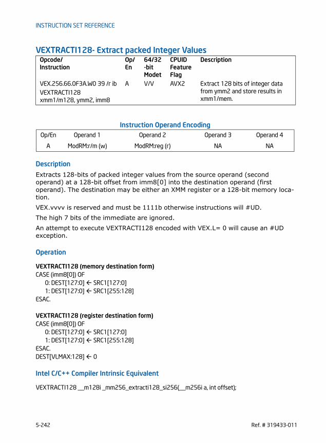
INSTRUCTION SET REFERENCE
VEXTRACTI128- Extract packed Integer Values
Instruction Operand Encoding
Description
Extracts 128-bits of packed integer values from the source operand (second operand) at a 128-bit offset from imm8[0] into the destination operand (first operand). The destination may be either an XMM register or a 128-bit memory loca-tion.VEX.vvvv is reserved and must be 1111b otherwise instructions will #UD.The high 7 bits of the immediate are ignored.An attempt to execute VEXTRACTI128 encoded with VEX.L= 0 will cause an #UD exception.
Operation
VEXTRACTI128 (memory destination form)CASE (imm8[0]) OF
0: DEST[127:0] SRC1[127:0]1: DEST[127:0] SRC1[255:128]
ESAC.
VEXTRACTI128 (register destination form)CASE (imm8[0]) OF
0: DEST[127:0] SRC1[127:0]1: DEST[127:0] SRC1[255:128]
ESAC.DEST[VLMAX:128] 0
Intel C/C++ Compiler Intrinsic Equivalent
VEXTRACTI128 __m128i _mm256_extracti128_si256(__m256i a, int offset);
Opcode/Instruction
Op/ En
64/32-bit Modet
CPUID Feature Flag
Description
VEX.256.66.0F3A.W0 39 /r ib A V/V AVX2 Extract 128 bits of integer data from ymm2 and store results in xmm1/mem.
VEXTRACTI128 xmm1/m128, ymm2, imm8
Op/En Operand 1 Operand 2 Operand 3 Operand 4
A ModRM:r/m (w) ModRM:reg (r) NA NA
5-242 Ref. # 319433-011

INSTRUCTION SET REFERENCE
SIMD Floating-Point Exceptions
None
Other ExceptionsSee Exceptions Type 6; additionally#UD IF VEX.L = 0,
If VEX.W = 1.
Ref. # 319433-011 5-243

INSTRUCTION SET REFERENCE
VINSERTI128- Insert packed Integer values
Instruction Operand Encoding
Description
Performs an insertion of 128-bits of packed integer data from the second source operand (third operand) into an the destination operand (first operand) at a 128-bit offset from imm8[0]. The remaining portions of the destination are written by the corresponding fields of the first source operand (second operand). The second source operand can be either an XMM register or a 128-bit memory location.The high 7 bits of the immediate are ignored.VEX.L must be 1; an attempt to execute this instruction with VEX.L=0 will cause #UD.
Operation
VINSERTI128TEMP[255:0] SRC1[255:0]CASE (imm8[0]) OF
0: TEMP[127:0] SRC2[127:0]1: TEMP[255:128] SRC2[127:0]
ESACDEST TEMP
Intel C/C++ Compiler Intrinsic Equivalent
VINSERTI128 __m256i _mm256_inserti128_si256 (__m256i a, __m128i b, int offset);
SIMD Floating-Point Exceptions
None
Opcode/Instruction
Op/ En
64/32-bit Mode
CPUID Feature Flag
Description
VEX.NDS.256.66.0F3A.W0 38 /r ib A V/V AVX2 Insert 128-bits of integer data from xmm3/mem and the remaining values from ymm2 into ymm1
VINSERTI128 ymm1, ymm2, xmm3/m128, imm8
Op/En Operand 1 Operand 2 Operand 3 Operand 4
A ModRM:reg (w) VEX.vvvv ModRM:r/m (r) NA
5-244 Ref. # 319433-011
INSTRUCTION SET REFERENCE
Other ExceptionsSee Exceptions Type 6; additionally#UD If VEX.L = 0,
If VEX.W = 1.
Ref. # 319433-011 5-245
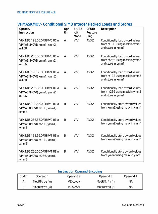
INSTRUCTION SET REFERENCE
VPMASKMOV- Conditional SIMD Integer Packed Loads and Stores
Instruction Operand Encoding
Opcode/Instruction
Op/ En
64/32-bit Mode
CPUID Feature Flag
Description
VEX.NDS.128.66.0F38.W0 8C /r A V/V AVX2 Conditionally load dword values from m128 using mask in xmm2 and store in xmm1
VPMASKMOVD xmm1, xmm2, m128
VEX.NDS.256.66.0F38.W0 8C /r A V/V AVX2 Conditionally load dword values from m256 using mask in ymm2 and store in ymm1
VPMASKMOVD ymm1, ymm2, m256
VEX.NDS.128.66.0F38.W1 8C /r A V/V AVX2 Conditionally load qword values from m128 using mask in xmm2 and store in xmm1
VPMASKMOVQ xmm1, xmm2, m128
VEX.NDS.256.66.0F38.W1 8C /r A V/V AVX2 Conditionally load qword values from m256 using mask in ymm2 and store in ymm1
VPMASKMOVQ ymm1, ymm2, m256
VEX.NDS.128.66.0F38.W0 8E /r B V/V AVX2 Conditionally store dword values from xmm2 using mask in xmm1VPMASKMOVD m128, xmm1,
xmm2
VEX.NDS.256.66.0F38.W0 8E /r B V/V AVX2 Conditionally store dword values from ymm2 using mask in ymm1VPMASKMOVD m256, ymm1,
ymm2
VEX.NDS.128.66.0F38.W1 8E /r B V/V AVX2 Conditionally store qword values from xmm2 using mask in xmm1VPMASKMOVQ m128, xmm1,
xmm2
VEX.NDS.256.66.0F38.W1 8E /r B V/V AVX2 Conditionally store qword values from ymm2 using mask in ymm1VPMASKMOVQ m256, ymm1,
ymm2
Op/En Operand 1 Operand 2 Operand 3 Operand 4
A ModRM:reg (w) VEX.vvvv ModRM:r/m (r) NA
B ModRM:r/m (w) VEX.vvvv ModRM:reg (r) NA
5-246 Ref. # 319433-011

INSTRUCTION SET REFERENCE
Description
Conditionally moves packed data elements from the second source operand into the corresponding data element of the destination operand, depending on the mask bits associated with each data element. The mask bits are specified in the first source operand. The mask bit for each data element is the most significant bit of that element in the first source operand. If a mask is 1, the corresponding data element is copied from the second source operand to the destination operand. If the mask is 0, the corre-sponding data element is set to zero in the load form of these instructions, and unmodified in the store form. The second source operand is a memory address for the load form of these instruc-tions. The destination operand is a memory address for the store form of these instructions. The other operands are either XMM registers (for VEX.128 version) or YMM registers (for VEX.256 version).Faults occur only due to mask-bit required memory accesses that caused the faults. Faults will not occur due to referencing any memory location if the corresponding mask bit for that memory location is 0. For example, no faults will be detected if the mask bits are all zero.Unlike previous MASKMOV instructions (MASKMOVQ and MASKMOVDQU), a nontem-poral hint is not applied to these instructionsInstruction behavior on alignment check reporting with mask bits of less than all 1s are the same as with mask bits of all 1s.VMASKMOV should not be used to access memory mapped I/O as the ordering of the individual loads or stores it does is implementation specific. In cases where mask bits indicate data should not be loaded or stored paging A and D bits will be set in an implementation dependent way. However, A and D bits are always set for pages where data is actually loaded/stored.Note: for load forms, the first source (the mask) is encoded in VEX.vvvv; the second source is encoded in rm_field, and the destination register is encoded in reg_field.Note: for store forms, the first source (the mask) is encoded in VEX.vvvv; the second source register is encoded in reg_field, and the destination memory location is encoded in rm_field.
Operation
VPMASKMOVD - 256-bit loadDEST[31:0] IF (SRC1[31]) Load_32(mem) ELSE 0 DEST[63:32] IF (SRC1[63]) Load_32(mem + 4) ELSE 0 DEST[95:64] IF (SRC1[95]) Load_32(mem + 8) ELSE 0 DEST[127:96] IF (SRC1[127]) Load_32(mem + 12) ELSE 0 DEST[159:128] IF (SRC1[159]) Load_32(mem + 16) ELSE 0 DEST[191:160] IF (SRC1[191]) Load_32(mem + 20) ELSE 0 DEST[223:192] IF (SRC1[223]) Load_32(mem + 24) ELSE 0
Ref. # 319433-011 5-247

INSTRUCTION SET REFERENCE
DEST[255:224] IF (SRC1[255]) Load_32(mem + 28) ELSE 0
VPMASKMOVD -128-bit load DEST[31:0] IF (SRC1[31]) Load_32(mem) ELSE 0 DEST[63:32] IF (SRC1[63]) Load_32(mem + 4) ELSE 0 DEST[95:64] IF (SRC1[95]) Load_32(mem + 8) ELSE 0 DEST[127:97] IF (SRC1[127]) Load_32(mem + 12) ELSE 0 DEST[VLMAX:128] 0
VPMASKMOVQ - 256-bit loadDEST[63:0] IF (SRC1[63]) Load_64(mem) ELSE 0 DEST[127:64] IF (SRC1[127]) Load_64(mem + 8) ELSE 0 DEST[195:128] IF (SRC1[191]) Load_64(mem + 16) ELSE 0 DEST[255:196] IF (SRC1[255]) Load_64(mem + 24) ELSE 0
VPMASKMOVQ - 128-bit load DEST[63:0] IF (SRC1[63]) Load_64(mem) ELSE 0 DEST[127:64] IF (SRC1[127]) Load_64(mem + 16) ELSE 0DEST[VLMAX:128] 0
VPMASKMOVD - 256-bit storeIF (SRC1[31]) DEST[31:0] SRC2[31:0] IF (SRC1[63]) DEST[63:32] SRC2[63:32] IF (SRC1[95]) DEST[95:64] SRC2[95:64] IF (SRC1[127]) DEST[127:96] SRC2[127:96] IF (SRC1[159]) DEST[159:128] SRC2[159:128] IF (SRC1[191]) DEST[191:160] SRC2[191:160] IF (SRC1[223]) DEST[223:192] SRC2[223:192] IF (SRC1[255]) DEST[255:224] SRC2[255:224]
VPMASKMOVD - 128-bit storeIF (SRC1[31]) DEST[31:0] SRC2[31:0] IF (SRC1[63]) DEST[63:32] SRC2[63:32] IF (SRC1[95]) DEST[95:64] SRC2[95:64] IF (SRC1[127]) DEST[127:96] SRC2[127:96]
VPMASKMOVQ - 256-bit storeIF (SRC1[63]) DEST[63:0] SRC2[63:0] IF (SRC1[127]) DEST[127:64] SRC2[127:64] IF (SRC1[191]) DEST[191:128] SRC2[191:128] IF (SRC1[255]) DEST[255:192] SRC2[255:192]
VPMASKMOVQ - 128-bit store
5-248 Ref. # 319433-011

INSTRUCTION SET REFERENCE
IF (SRC1[63]) DEST[63:0] SRC2[63:0] IF (SRC1[127]) DEST[127:64] SRC2[127:64]
Intel C/C++ Compiler Intrinsic Equivalent
VPMASKMOVD __m256i _mm256_maskload_epi32(int const *a, __m256i mask)
VPMASKMOVD void _mm256_maskstore_epi32(int *a, __m256i mask, __m256i b)
VPMASKMOVQ __m256i _mm256_maskload_epi64(__int64 const *a, __m256i mask);
VPMASKMOVQ void _mm256_maskstore_epi64(__int64 *a, __m256i mask, __m256d b);
VPMASKMOVD __m128i _mm_maskload_epi32(int const *a, __m128i mask)
VPMASKMOVD void _mm_maskstore_epi32(int *a, __m128i mask, __m128 b)
VPMASKMOVQ __m128i _mm_maskload_epi64(__int cont *a, __m128i mask);
VPMASKMOVQ void _mm_maskstore_epi64(__int64 *a, __m128i mask, __m128i b);
SIMD Floating-Point Exceptions
None
Other ExceptionsSee Exceptions Type 6 (No AC# reported for any mask bit combinations).
Ref. # 319433-011 5-249

INSTRUCTION SET REFERENCE
VPSLLVD/VPSLLVQ - Variable Bit Shift Left Logical
Instruction Operand Encoding
Description
Shifts the bits in the individual data elements (doublewords, or quadword) in the first source operand to the left by the count value of respective data elements in the second source operand. As the bits in the data elements are shifted left, the empty low-order bits are cleared (set to 0). The count values are specified individually in each data element of the second source operand. If the unsigned integer value specified in the respective data element of the second source operand is greater than 31 (for doublewords), or 63 (for a quadword), then the destination data element are written with 0.
Opcode/Instruction
Op/ En
64/32-bit Mode
CPUID Feature Flag
Description
VEX.NDS.128.66.0F38.W0 47 /r A V/V AVX2 Shift doublewords in xmm2 left by amount specified in the cor-responding element of xmm3/m128 while shifting in 0s.
VPSLLVD xmm1, xmm2, xmm3/m128
VEX.NDS.128.66.0F38.W1 47 /r A V/V AVX2 Shift quadwords in xmm2 left by amount specified in the cor-responding element of xmm3/m128 while shifting in 0s.
VPSLLVQ xmm1, xmm2, xmm3/m128
VEX.NDS.256.66.0F38.W0 47 /r A V/V AVX2 Shift doublewords in ymm2 left by amount specified in the cor-responding element of ymm3/m256 while shifting in 0s.
VPSLLVD ymm1, ymm2, ymm3/m256
VEX.NDS.256.66.0F38.W1 47 /r A V/V AVX2 Shift quadwords in ymm2 left by amount specified in the cor-responding element of ymm3/m256 while shifting in 0s.
VPSLLVQ ymm1, ymm2, ymm3/m256
Op/En Operand 1 Operand 2 Operand 3 Operand 4
A ModRM:reg (w) VEX.vvvv ModRM:r/m (r) NA
5-250 Ref. # 319433-011

INSTRUCTION SET REFERENCE
VEX.128 encoded version: The destination and first source operands are XMM regis-ters. The count operand can be either an XMM register or a 128-bit memory location. Bits (255:128) of the corresponding YMM register are zeroed.VEX.256 encoded version: The destination and first source operands are YMM regis-ters. The count operand can be either an YMM register or a 256-bit memory location.
Operation
VPSLLVD (VEX.128 version)COUNT_0 SRC2[31 : 0]
(* Repeat Each COUNT_i for the 2nd through 4th dwords of SRC2*)COUNT_3 SRC2[127 : 96];IF COUNT_0 < 32 THENDEST[31:0] ZeroExtend(SRC1[31:0] << COUNT_0);ELSEDEST[31:0] 0;
(* Repeat shift operation for 2nd through 4th dwords *)IF COUNT_3 < 32 THENDEST[127:96] ZeroExtend(SRC1[127:96] << COUNT_3);ELSEDEST[127:96] 0;DEST[VLMAX:128] 0;
VPSLLVD (VEX.256 version)COUNT_0 SRC2[31 : 0];
(* Repeat Each COUNT_i for the 2nd through 7th dwords of SRC2*)COUNT_7 SRC2[255 : 224];IF COUNT_0 < 32 THENDEST[31:0] ZeroExtend(SRC1[31:0] << COUNT_0);ELSEDEST[31:0] 0;
(* Repeat shift operation for 2nd through 7th dwords *)IF COUNT_7 < 32 THENDEST[255:224] ZeroExtend(SRC1[255:224] << COUNT_7);ELSEDEST[255:224] 0;
VPSLLVQ (VEX.128 version)COUNT_0 SRC2[63 : 0];COUNT_1 SRC2[127 : 64];IF COUNT_0 < 64THENDEST[63:0] ZeroExtend(SRC1[63:0] << COUNT_0);ELSEDEST[63:0] 0;
Ref. # 319433-011 5-251

INSTRUCTION SET REFERENCE
IF COUNT_1 < 64 THENDEST[127:64] ZeroExtend(SRC1[127:64] << COUNT_1);ELSEDEST[127:96] 0;DEST[VLMAX:128] 0;
VPSLLVQ (VEX.256 version)COUNT_0 SRC2[5 : 0];
(* Repeat Each COUNT_i for the 2nd through 4th dwords of SRC2*)COUNT_3 SRC2[197 : 192];IF COUNT_0 < 64THENDEST[63:0] ZeroExtend(SRC1[63:0] << COUNT_0);ELSEDEST[63:0] 0;
(* Repeat shift operation for 2nd through 4th dwords *)IF COUNT_3 < 64 THENDEST[255:192] ZeroExtend(SRC1[255:192] << COUNT_3);ELSEDEST[255:192] 0;
Intel C/C++ Compiler Intrinsic Equivalent
VPSLLVD __m256i _mm256_sllv_epi32 (__m256i m, __m256i count)
VPSLLVD __m128i _mm_sllv_epi32 (__m128i m, __m128i count)
VPSLLVQ __m256i _mm256_sllv_epi64 (__m256i m, __m256i count)
VPSLLVQ __m128i _mm_sllv_epi64 (__m128i m, __m128i count)
SIMD Floating-Point Exceptions
None
Other ExceptionsSee Exceptions Type 4
5-252 Ref. # 319433-011

INSTRUCTION SET REFERENCE
VPSRAVD - Variable Bit Shift Right Arithmetic
Instruction Operand Encoding
Description
Shifts the bits in the individual doubleword data elements in the first source operand to the right by the count value of respective data elements in the second source operand. As the bits in each data element are shifted right, the empty high-order bits are filled with the sign bit of the source element. The count values are specified individually in each data element of the second source operand. If the unsigned integer value specified in the respective data element of the second source operand is greater than 31, then the destination data element are filled with the corresponding sign bit of the source element. VEX.128 encoded version: The destination and first source operands are XMM regis-ters. The count operand can be either an XMM register or a 128-bit memory location. Bits (255:128) of the corresponding YMM register are zeroed.VEX.256 encoded version: The destination and first source operands are YMM regis-ters. The count operand can be either an YMM register or a 256-bit memory location.
Operation
VPSRAVD (VEX.128 version)COUNT_0 SRC2[31: 0]
(* Repeat Each COUNT_i for the 2nd through 4th dwords of SRC2*)COUNT_3 SRC2[127 : 112];IF COUNT_0 < 32 THEN
Opcode/Instruction
Op/ En
64/32-bit Mode
CPUID Feature Flag
Description
VEX.NDS.128.66.0F38.W0 46 /r A V/V AVX2 Shift doublewords in xmm2 right by amount specified in the corre-sponding element of xmm3/m128 while shifting in the sign bits.
VPSRAVD xmm1, xmm2, xmm3/m128
VEX.NDS.256.66.0F38.W0 46 /r A V/V AVX2 Shift doublewords in ymm2 right by amount specified in the corre-sponding element of ymm3/m256 while shifting in the sign bits.
VPSRAVD ymm1, ymm2, ymm3/m256
Op/En Operand 1 Operand 2 Operand 3 Operand 4
A ModRM:reg (w) VEX.vvvv ModRM:r/m (r) NA
Ref. # 319433-011 5-253

INSTRUCTION SET REFERENCE
DEST[31:0] SignExtend(SRC1[31:0] >> COUNT_0);ELSE
For (i = 0 to 31) DEST[i + 0] (SRC1[31] );FI;
(* Repeat shift operation for 2nd through 4th dwords *)IF COUNT_3 < 32 THEN
DEST[127:96] SignExtend(SRC1[127:96] >> COUNT_3);ELSE
For (i = 0 to 31) DEST[i + 96] (SRC1[127] );FI;DEST[VLMAX:128] 0;
VPSRAVD (VEX.256 version)COUNT_0 SRC2[31 : 0];
(* Repeat Each COUNT_i for the 2nd through 7th dwords of SRC2*)COUNT_7 SRC2[255 : 224];IF COUNT_0 < 32 THEN
DEST[31:0] SignExtend(SRC1[31:0] >> COUNT_0);ELSE
For (i = 0 to 31) DEST[i + 0] (SRC1[31] );FI;
(* Repeat shift operation for 2nd through 7th dwords *)IF COUNT_7 < 32 THEN
DEST[255:224] SignExtend(SRC1[255:224] >> COUNT_7);ELSE
For (i = 0 to 31) DEST[i + 224] (SRC1[255] );FI;
Intel C/C++ Compiler Intrinsic Equivalent
VPSRAVD __m256i _mm256_srav_epi32 (__m256i m, __m256i count)
VPSRAVD __m128i _mm_srav_epi32 (__m128i m, __m128i count)
SIMD Floating-Point Exceptions
None
Other ExceptionsSee Exceptions Type 4; additionally#UD If VEX.W = 1.
5-254 Ref. # 319433-011

INSTRUCTION SET REFERENCE
VPSRLVD/VPSRLVQ - Variable Bit Shift Right Logical
Instruction Operand Encoding
Description
Shifts the bits in the individual data elements (doublewords, or quadword) in the first source operand to the right by the count value of respective data elements in the second source operand. As the bits in the data elements are shifted right, the empty high-order bits are cleared (set to 0). The count values are specified individually in each data element of the second source operand. If the unsigned integer value specified in the respective data element of the second source operand is greater than 31 (for doublewords), or 63 (for a quadword), then the destination data element are written with 0.
Opcode/Instruction
Op/EN
64/32-bit Mode
CPUID Feature Flag
Description
VEX.NDS.128.66.0F38.W0 45 /r A V/V AVX2 Shift doublewords in xmm2 right by amount specified in the corresponding element of xmm3/m128 while shifting in 0s.
VPSRLVD xmm1, xmm2, xmm3/m128
VEX.NDS.128.66.0F38.W1 45 /r A V/V AVX2 Shift quadwords in xmm2 right by amount specified in the cor-responding element of xmm3/m128 while shifting in 0s.
VPSRLVQ xmm1, xmm2, xmm3/m128
VEX.NDS.256.66.0F38.W0 45 /r A V/V AVX2 Shift doublewords in ymm2 right by amount specified in the corresponding element of ymm3/m256 while shifting in 0s.
VPSRLVD ymm1, ymm2, ymm3/m256
VEX.NDS.256.66.0F38.W1 45 /r A V/V AVX2 Shift quadwords in ymm2 right by amount specified in the cor-responding element of ymm3/m256 while shifting in 0s.
VPSRLVQ ymm1, ymm2, ymm3/m256
Op/En Operand 1 Operand 2 Operand 3 Operand 4
A ModRM:reg (w) VEX.vvvv ModRM:r/m (r) NA
Ref. # 319433-011 5-255

INSTRUCTION SET REFERENCE
VEX.128 encoded version: The destination and first source operands are XMM regis-ters. The count operand can be either an XMM register or a 128-bit memory location. Bits (255:128) of the corresponding YMM register are zeroed.VEX.256 encoded version: The destination and first source operands are YMM regis-ters. The count operand can be either an YMM register or a 256-bit memory location.
Operation
VPSRLVD (VEX.128 version)COUNT_0 SRC2[31 : 0]
(* Repeat Each COUNT_i for the 2nd through 4th dwords of SRC2*)COUNT_3 SRC2[127 : 96];IF COUNT_0 < 32 THENDEST[31:0] ZeroExtend(SRC1[31:0] >> COUNT_0);ELSEDEST[31:0] 0;
(* Repeat shift operation for 2nd through 4th dwords *)IF COUNT_3 < 32 THENDEST[127:96] ZeroExtend(SRC1[127:96] >> COUNT_3);ELSEDEST[127:96] 0;DEST[VLMAX:128] 0;
VPSRLVD (VEX.256 version)COUNT_0 SRC2[31 : 0];
(* Repeat Each COUNT_i for the 2nd through 7th dwords of SRC2*)COUNT_7 SRC2[255 : 224];IF COUNT_0 < 32 THENDEST[31:0] ZeroExtend(SRC1[31:0] >> COUNT_0);ELSEDEST[31:0] 0;
(* Repeat shift operation for 2nd through 7th dwords *)IF COUNT_7 < 32 THENDEST[255:224] ZeroExtend(SRC1[255:224] >> COUNT_7);ELSEDEST[255:224] 0;
VPSRLVQ (VEX.128 version)COUNT_0 SRC2[63 : 0];COUNT_1 SRC2[127 : 64];IF COUNT_0 < 64 THENDEST[63:0] ZeroExtend(SRC1[63:0] >> COUNT_0);ELSEDEST[63:0] 0;
5-256 Ref. # 319433-011

INSTRUCTION SET REFERENCE
IF COUNT_1 < 64THENDEST[127:64] ZeroExtend(SRC1[127:64] >> COUNT_1);ELSEDEST[127:64] 0;DEST[VLMAX:128] 0;
VPSRLVQ (VEX.256 version)COUNT_0 SRC2[63 : 0];
(* Repeat Each COUNT_i for the 2nd through 4th dwords of SRC2*)COUNT_3 SRC2[255 : 192];IF COUNT_0 < 64 THENDEST[63:0] ZeroExtend(SRC1[63:0] >> COUNT_0);ELSEDEST[63:0] 0;
(* Repeat shift operation for 2nd through 4th dwords *)IF COUNT_3 < 64THENDEST[255:192] ZeroExtend(SRC1[255:192] >> COUNT_3);ELSEDEST[255:192] 0;
Intel C/C++ Compiler Intrinsic Equivalent
VPSRLVD __m256i _mm256_srlv_epi32 (__m256i m, __m256i count);
VPSRLVD __m128i _mm_srlv_epi32 (__m128i m, __m128i count);
VPSRLVQ __m256i _mm256_srlv_epi64 (__m256i m, __m256i count);
VPSRLVQ __m128i _mm_srlv_epi64 (__m128i m, __m128i count);
SIMD Floating-Point Exceptions
None
Other ExceptionsSee Exceptions Type 4
Ref. # 319433-011 5-257
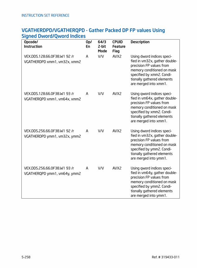
INSTRUCTION SET REFERENCE
VGATHERDPD/VGATHERQPD - Gather Packed DP FP values Using Signed Dword/Qword Indices
Opcode/Instruction
Op/ En
64/32-bit Mode
CPUID Feature Flag
Description
VEX.DDS.128.66.0F38.W1 92 /r A V/V AVX2 Using dword indices speci-fied in vm32x, gather double-precision FP values from memory conditioned on mask specified by xmm2. Condi-tionally gathered elements are merged into xmm1.
VGATHERDPD xmm1, vm32x, xmm2
VEX.DDS.128.66.0F38.W1 93 /r A V/V AVX2 Using qword indices speci-fied in vm64x, gather double-precision FP values from memory conditioned on mask specified by xmm2. Condi-tionally gathered elements are merged into xmm1.
VGATHERQPD xmm1, vm64x, xmm2
VEX.DDS.256.66.0F38.W1 92 /r A V/V AVX2 Using dword indices speci-fied in vm32x, gather double-precision FP values from memory conditioned on mask specified by ymm2. Condi-tionally gathered elements are merged into ymm1.
VGATHERDPD ymm1, vm32x, ymm2
VEX.DDS.256.66.0F38.W1 93 /r A V/V AVX2 Using qword indices speci-fied in vm64y, gather double-precision FP values from memory conditioned on mask specified by ymm2. Condi-tionally gathered elements are merged into ymm1.
VGATHERQPD ymm1, vm64y, ymm2
5-258 Ref. # 319433-011

INSTRUCTION SET REFERENCE
Instruction Operand Encoding
Description
The instruction conditionally loads up to 2 or 4 double-precision floating-point values from memory addresses specified by the memory operand (the second operand) and using qword indices. The memory operand uses the VSIB form of the SIB byte to specify a general purpose register operand as the common base, a vector register for an array of indices relative to the base and a constant scale factor.The mask operand (the third operand) specifies the conditional load operation from each memory address and the corresponding update of each data element of the destination operand (the first operand). Conditionality is specified by the most signif-icant bit of each data element of the mask register. If an element’s mask bit is not set, the corresponding element of the destination register is left unchanged. The width of data element in the destination register and mask register are identical. The entire mask register will be set to zero by this instruction unless the instruction causes an exception. Using dword indices in the lower half of the mask register, the instruction condition-ally loads up to 2 or 4 double-precision floating-point values from the VSIB addressing memory operand, and updates the destination register. This instruction can be suspended by an exception if at least one element is already gathered (i.e., if the exception is triggered by an element other than the rightmost one with its mask bit set). When this happens, the destination register and the mask operand are partially updated; those elements that have been gathered are placed into the destination register and have their mask bits set to zero. If any traps or interrupts are pending from already gathered elements, they will be delivered in lieu of the exception; in this case, EFLAG.RF is set to one so an instruction breakpoint is not re-triggered when the instruction is continued.If the data size and index size are different, part of the destination register and part of the mask register do not correspond to any elements being gathered. This instruc-tion sets those parts to zero. It may do this to one or both of those registers even if the instruction triggers an exception, and even if the instruction triggers the excep-tion before gathering any elements.VEX.128 version: The instruction will gather two double-precision floating-point values. For dword indices, only the lower two indices in the vector index register are used.VEX.256 version: The instruction will gather four double-precision floating-point values. For dword indices, only the lower four indices in the vector index register are used.Note that:
Op/En Operand 1 Operand 2 Operand 3 Operand 4
A ModRM:reg (r,w) BaseReg (R): VSIB:base,VectorReg(R): VSIB:index
VEX.vvvv (r, w) NA
Ref. # 319433-011 5-259

INSTRUCTION SET REFERENCE
• If any pair of the index, mask, or destination registers are the same, this instruction results a GP fault.
• The values may be read from memory in any order. Memory ordering with other instructions follows the Intel-64 memory-ordering model.
• Faults are delivered in a right-to-left manner. That is, if a fault is triggered by an element and delivered, all elements closer to the LSB of the destination will be completed (and non-faulting). Individual elements closer to the MSB may or may not be completed. If a given element triggers multiple faults, they are delivered in the conventional order.
• Elements may be gathered in any order, but faults must be delivered in a right-to-left order; thus, elements to the left of a faulting one may be gathered before the fault is delivered. A given implementation of this instruction is repeatable - given the same input values and architectural state, the same set of elements to the left of the faulting one will be gathered.
• This instruction does not perform AC checks, and so will never deliver an AC fault.• This instruction will cause a #UD if the address size attribute is 16-bit.• This instruction should not be used to access memory mapped I/O as the
ordering of the individual loads it does is implementation specific, and some implementations may use loads larger than the data element size or load elements an indeterminate number of times.
• The scaled index may require more bits to represent than the address bits used by the processor (e.g., in 32-bit mode, if the scale is greater than one). In this case, the most significant bits beyond the number of address bits are ignored.
Operation
DEST SRC1;BASE_ADDR: base register encoded in VSIB addressing;VINDEX: the vector index register encoded by VSIB addressing;SCALE: scale factor encoded by SIB:[7:6];DISP: optional 1, 2, 4 byte displacement;MASK SRC3;
VGATHERDPD (VEX.128 version)FOR j 0 to 1
i j * 64;IF MASK[63+i] THEN
MASK[i +63:i] 0xFFFFFFFF_FFFFFFFF; // extend from most significant bitELSE
MASK[i +63:i] 0;FI;
ENDFORFOR j 0 to 1
5-260 Ref. # 319433-011

INSTRUCTION SET REFERENCE
k j * 32;i j * 64;DATA_ADDR BASE_ADDR + (SignExtend(VINDEX[k+31:k])*SCALE + DISP;IF MASK[63+i] THEN
DEST[i +63:i] FETCH_64BITS(DATA_ADDR); // a fault exits the loopFI;MASK[i +63: i] 0;
ENDFORMASK[VLMAX:128] 0;DEST[VLMAX:128] 0;(non-masked elements of the mask register have the content of respective element cleared)
VGATHERQPD (VEX.128 version)FOR j 0 to 1
i j * 64;IF MASK[63+i] THEN
MASK[i +63:i] 0xFFFFFFFF_FFFFFFFF; // extend from most significant bitELSE
MASK[i +63:i] 0;FI;
ENDFORFOR j 0 to 1
i j * 64;DATA_ADDR BASE_ADDR + (SignExtend(VINDEX1[i+63:i])*SCALE + DISP;IF MASK[63+i] THEN
DEST[i +63:i] FETCH_64BITS(DATA_ADDR); // a fault exits this loopFI;MASK[i +63: i] 0;
ENDFORMASK[VLMAX:128] 0;DEST[VLMAX:128] 0;(non-masked elements of the mask register have the content of respective element cleared)
VGATHERQPD (VEX.256 version)FOR j 0 to 3
i j * 64;IF MASK[63+i] THEN
MASK[i +63:i] 0xFFFFFFFF_FFFFFFFF; // extend from most significant bitELSE
MASK[i +63:i] 0;FI;
ENDFORFOR j 0 to 3
Ref. # 319433-011 5-261

INSTRUCTION SET REFERENCE
i j * 64;DATA_ADDR BASE_ADDR + (SignExtend(VINDEX1[i+63:i])*SCALE + DISP;IF MASK[63+i] THEN
DEST[i +63:i] FETCH_64BITS(DATA_ADDR); // a fault exits the loopFI;MASK[i +63: i] 0;
ENDFOR(non-masked elements of the mask register have the content of respective element cleared)
VGATHERDPD (VEX.256 version)FOR j 0 to 3
i j * 64;IF MASK[63+i] THEN
MASK[i +63:i] 0xFFFFFFFF_FFFFFFFF; // extend from most significant bitELSE
MASK[i +63:i] 0;FI;
ENDFORFOR j 0 to 3
k j * 32;i j * 64;DATA_ADDR BASE_ADDR + (SignExtend(VINDEX1[k+31:k])*SCALE + DISP;IF MASK[63+i] THEN
DEST[i +63:i] FETCH_64BITS(DATA_ADDR); // a fault exits the loopFI;MASK[i +63:i] 0;
ENDFOR(non-masked elements of the mask register have the content of respective element cleared)
Intel C/C++ Compiler Intrinsic Equivalent
VGATHERDPD __m128d _mm_i32gather_pd (double const * base, __m128i index, const int scale);
VGATHERDPD __m128d _mm_mask_i32gather_pd (__m128d src, double const * base, __m128i index, __m128d mask, const int scale);
VGATHERDPD __m256d _mm256_i32gather_pd (double const * base, __m128i index, const int scale);
VGATHERDPD __m256d _mm256_mask_i32gather_pd (__m256d src, double const * base, __m128i index, __m256d mask, const int scale);
VGATHERQPD __m128d _mm_i64gather_pd (double const * base, __m128i index, const int scale);
VGATHERQPD __m128d _mm_mask_i64gather_pd (__m128d src, double const * base, __m128i index, __m128d mask, const int scale);
5-262 Ref. # 319433-011

INSTRUCTION SET REFERENCE
VGATHERQPD __m256d _mm256_i64gather_pd (double const * base, __m256i index, const int scale);
VGATHERQPD __m256d _mm256_mask_i64gather_pd (__m256d src, double const * base, __m256i index, __m256d mask, const int scale);
SIMD Floating-Point Exceptions
None
Other ExceptionsSee Exceptions Type 12
Ref. # 319433-011 5-263

INSTRUCTION SET REFERENCE
VGATHERDPS/VGATHERQPS - Gather Packed SP FP values Using Signed Dword/Qword Indices
Opcode/Instruction
Op/ En
64/32-bit Mode
CPUID Feature Flag
Description
VEX.DDS.128.66.0F38.W0 92 /r A V/V AVX2 Using dword indices speci-fied in vm32x, gather single-precision FP values from memory conditioned on mask specified by xmm2. Conditionally gathered ele-ments are merged into xmm1.
VGATHERDPS xmm1, vm32x, xmm2
VEX.DDS.128.66.0F38.W0 93 /r A V/V AVX2 Using qword indices speci-fied in vm64x, gather single-precision FP values from memory conditioned on mask specified by xmm2. Conditionally gathered ele-ments are merged into xmm1.
VGATHERQPS xmm1, vm64x, xmm2
VEX.DDS.256.66.0F38.W0 92 /r A V/V AVX2 Using dword indices speci-fied in vm32y, gather single-precision FP values from memory conditioned on mask specified by ymm2. Conditionally gathered ele-ments are merged into ymm1.
VGATHERDPS ymm1, vm32y, ymm2
VEX.DDS.256.66.0F38.W0 93 /r A V/V AVX2 Using qword indices speci-fied in vm64y, gather single-precision FP values from memory conditioned on mask specified by xmm2. Conditionally gathered ele-ments are merged into xmm1.
VGATHERQPS xmm1, vm64y, xmm2
5-264 Ref. # 319433-011

INSTRUCTION SET REFERENCE
Instruction Operand Encoding
Description
The instruction conditionally loads up to 4 or 8 single-precision floating-point values from memory addresses specified by the memory operand (the second operand) and using dword indices. The memory operand uses the VSIB form of the SIB byte to specify a general purpose register operand as the common base, a vector register for an array of indices relative to the base and a constant scale factor.The mask operand (the third operand) specifies the conditional load operation from each memory address and the corresponding update of each data element of the destination operand (the first operand). Conditionality is specified by the most signif-icant bit of each data element of the mask register. If an element’s mask bit is not set, the corresponding element of the destination register is left unchanged. The width of data element in the destination register and mask register are identical. The entire mask register will be set to zero by this instruction unless the instruction causes an exception. Using qword indices, the instruction conditionally loads up to 2 or 4 single-precision floating-point values from the VSIB addressing memory operand, and updates the lower half of the destination register. The upper 128 or 256 bits of the destination register are zero’ed with qword indices.This instruction can be suspended by an exception if at least one element is already gathered (i.e., if the exception is triggered by an element other than the rightmost one with its mask bit set). When this happens, the destination register and the mask operand are partially updated; those elements that have been gathered are placed into the destination register and have their mask bits set to zero. If any traps or interrupts are pending from already gathered elements, they will be delivered in lieu of the exception; in this case, EFLAG.RF is set to one so an instruction breakpoint is not re-triggered when the instruction is continued.If the data size and index size are different, part of the destination register and part of the mask register do not correspond to any elements being gathered. This instruc-tion sets those parts to zero. It may do this to one or both of those registers even if the instruction triggers an exception, and even if the instruction triggers the excep-tion before gathering any elements.VEX.128 version: For dword indices, the instruction will gather four single-precision floating-point values. For qword indices, the instruction will gather two values and zeroes the upper 64 bits of the destination.VEX.256 version: For dword indices, the instruction will gather eight single-precision floating-point values. For qword indices, the instruction will gather four values and zeroes the upper 128 bits of the destination.Note that:
Op/En Operand 1 Operand 2 Operand 3 Operand 4
A ModRM:reg (r,w) BaseReg (R): VSIB:base,VectorReg(R): VSIB:index
VEX.vvvv (r, w) NA
Ref. # 319433-011 5-265
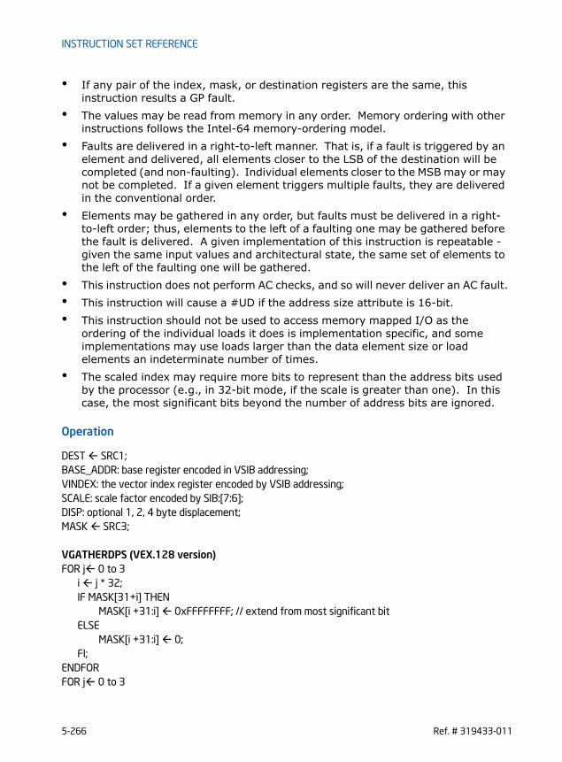
INSTRUCTION SET REFERENCE
• If any pair of the index, mask, or destination registers are the same, this instruction results a GP fault.
• The values may be read from memory in any order. Memory ordering with other instructions follows the Intel-64 memory-ordering model.
• Faults are delivered in a right-to-left manner. That is, if a fault is triggered by an element and delivered, all elements closer to the LSB of the destination will be completed (and non-faulting). Individual elements closer to the MSB may or may not be completed. If a given element triggers multiple faults, they are delivered in the conventional order.
• Elements may be gathered in any order, but faults must be delivered in a right-to-left order; thus, elements to the left of a faulting one may be gathered before the fault is delivered. A given implementation of this instruction is repeatable - given the same input values and architectural state, the same set of elements to the left of the faulting one will be gathered.
• This instruction does not perform AC checks, and so will never deliver an AC fault.• This instruction will cause a #UD if the address size attribute is 16-bit.• This instruction should not be used to access memory mapped I/O as the
ordering of the individual loads it does is implementation specific, and some implementations may use loads larger than the data element size or load elements an indeterminate number of times.
• The scaled index may require more bits to represent than the address bits used by the processor (e.g., in 32-bit mode, if the scale is greater than one). In this case, the most significant bits beyond the number of address bits are ignored.
Operation
DEST SRC1;BASE_ADDR: base register encoded in VSIB addressing;VINDEX: the vector index register encoded by VSIB addressing;SCALE: scale factor encoded by SIB:[7:6];DISP: optional 1, 2, 4 byte displacement;MASK SRC3;
VGATHERDPS (VEX.128 version)FOR j 0 to 3
i j * 32;IF MASK[31+i] THEN
MASK[i +31:i] 0xFFFFFFFF; // extend from most significant bitELSE
MASK[i +31:i] 0;FI;
ENDFORFOR j 0 to 3
5-266 Ref. # 319433-011
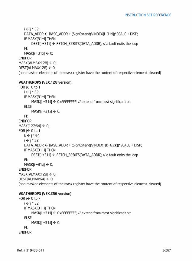
INSTRUCTION SET REFERENCE
i j * 32;DATA_ADDR BASE_ADDR + (SignExtend(VINDEX[i+31:i])*SCALE + DISP;IF MASK[31+i] THEN
DEST[i +31:i] FETCH_32BITS(DATA_ADDR); // a fault exits the loopFI;MASK[i +31:i] 0;
ENDFORMASK[VLMAX:128] 0;DEST[VLMAX:128] 0;(non-masked elements of the mask register have the content of respective element cleared)
VGATHERQPS (VEX.128 version)FOR j 0 to 1
i j * 32;IF MASK[31+i] THEN
MASK[i +31:i] 0xFFFFFFFF; // extend from most significant bitELSE
MASK[i +31:i] 0;FI;
ENDFORMASK[127:64] 0;FOR j 0 to 1
k j * 64;i j * 32;DATA_ADDR BASE_ADDR + (SignExtend(VINDEX1[k+63:k])*SCALE + DISP;IF MASK[31+i] THEN
DEST[i +31:i] FETCH_32BITS(DATA_ADDR); // a fault exits the loopFI;MASK[i +31:i] 0;
ENDFORMASK[VLMAX:128] 0;DEST[VLMAX:64] 0;(non-masked elements of the mask register have the content of respective element cleared)
VGATHERDPS (VEX.256 version)FOR j 0 to 7
i j * 32;IF MASK[31+i] THEN
MASK[i +31:i] 0xFFFFFFFF; // extend from most significant bitELSE
MASK[i +31:i] 0;FI;
ENDFOR
Ref. # 319433-011 5-267

INSTRUCTION SET REFERENCE
FOR j 0 to 7i j * 32;DATA_ADDR BASE_ADDR + (SignExtend(VINDEX1[i+31:i])*SCALE + DISP;IF MASK[31+i] THEN
DEST[i +31:i] FETCH_32BITS(DATA_ADDR); // a fault exits the loopFI;MASK[i +31:i] 0;
ENDFOR(non-masked elements of the mask register have the content of respective element cleared)
VGATHERQPS (VEX.256 version)FOR j 0 to 3
i j * 32;IF MASK[31+i] THEN
MASK[i +31:i] 0xFFFFFFFF; // extend from most significant bitELSE
MASK[i +31:i] 0;FI;
ENDFORMASK[255:128] 0;FOR j 0 to 3
k j * 64;i j * 32;DATA_ADDR BASE_ADDR + (SignExtend(VINDEX1[k+63:k])*SCALE + DISP;IF MASK[31+i] THEN
DEST[i +31:i] FETCH_32BITS(DATA_ADDR); // a fault exits the loopFI;MASK[i +31:i] 0;
ENDFORMASK[VLMAX:128] 0;DEST[VLMAX:128] 0;(non-masked elements of the mask register have the content of respective element cleared)
Intel C/C++ Compiler Intrinsic Equivalent
VGATHERDPS __m128 _mm_i32gather_ps (float const * base, __m128i index, const int scale);
VGATHERDPS __m128 _mm_mask_i32gather_ps (__m128 src, float const * base, __m128i index, __m128 mask, const int scale);
VGATHERDPS __m256 _mm256_i32gather_ps (float const * base, __m256i index, const int scale);
VGATHERDPS __m256 _mm256_mask_i32gather_ps (__m256 src, float const * base, __m256i index, __m256 mask, const int scale);
5-268 Ref. # 319433-011
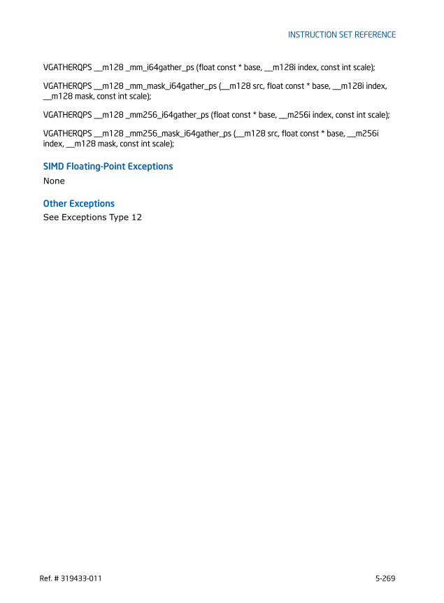
INSTRUCTION SET REFERENCE
VGATHERQPS __m128 _mm_i64gather_ps (float const * base, __m128i index, const int scale);
VGATHERQPS __m128 _mm_mask_i64gather_ps (__m128 src, float const * base, __m128i index, __m128 mask, const int scale);
VGATHERQPS __m128 _mm256_i64gather_ps (float const * base, __m256i index, const int scale);
VGATHERQPS __m128 _mm256_mask_i64gather_ps (__m128 src, float const * base, __m256i index, __m128 mask, const int scale);
SIMD Floating-Point Exceptions
None
Other ExceptionsSee Exceptions Type 12
Ref. # 319433-011 5-269
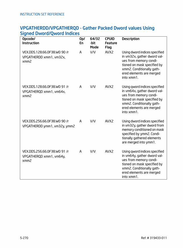
INSTRUCTION SET REFERENCE
VPGATHERDD/VPGATHERQD - Gather Packed Dword values Using Signed Dword/Qword Indices
Opcode/Instruction
Op/ En
64/32-bit Mode
CPUID Feature Flag
Description
VEX.DDS.128.66.0F38.W0 90 /r A V/V AVX2 Using dword indices specified in vm32x, gather dword val-ues from memory condi-tioned on mask specified by xmm2. Conditionally gath-ered elements are merged into xmm1.
VPGATHERDD xmm1, vm32x, xmm2
VEX.DDS.128.66.0F38.W0 91 /r A V/V AVX2 Using qword indices specified in vm64x, gather dword val-ues from memory condi-tioned on mask specified by xmm2. Conditionally gath-ered elements are merged into xmm1.
VPGATHERQD xmm1, vm64x, xmm2
VEX.DDS.256.66.0F38.W0 90 /r A V/V AVX2 Using dword indices specified in vm32y, gather dword from memory conditioned on mask specified by ymm2. Condi-tionally gathered elements are merged into ymm1.
VPGATHERDD ymm1, vm32y, ymm2
VEX.DDS.256.66.0F38.W0 91 /r A V/V AVX2 Using qword indices specified in vm64y, gather dword val-ues from memory condi-tioned on mask specified by xmm2. Conditionally gath-ered elements are merged into xmm1.
VPGATHERQD xmm1, vm64y, xmm2
5-270 Ref. # 319433-011

INSTRUCTION SET REFERENCE
Instruction Operand Encoding
Description
The instruction conditionally loads up to 4 or 8 dword values from memory addresses specified by the memory operand (the second operand) and using dword indices. The memory operand uses the VSIB form of the SIB byte to specify a general purpose register operand as the common base, a vector register for an array of indices rela-tive to the base and a constant scale factor.The mask operand (the third operand) specifies the conditional load operation from each memory address and the corresponding update of each data element of the destination operand (the first operand). Conditionality is specified by the most signif-icant bit of each data element of the mask register. If an element’s mask bit is not set, the corresponding element of the destination register is left unchanged. The width of data element in the destination register and mask register are identical. The entire mask register will be set to zero by this instruction unless the instruction causes an exception. Using qword indices, the instruction conditionally loads up to 2 or 4 dword values from the VSIB addressing memory operand, and updates the lower half of the desti-nation register. The upper 128 or 256 bits of the destination register are zero’ed with qword indices.This instruction can be suspended by an exception if at least one element is already gathered (i.e., if the exception is triggered by an element other than the rightmost one with its mask bit set). When this happens, the destination register and the mask operand are partially updated; those elements that have been gathered are placed into the destination register and have their mask bits set to zero. If any traps or interrupts are pending from already gathered elements, they will be delivered in lieu of the exception; in this case, EFLAG.RF is set to one so an instruction breakpoint is not re-triggered when the instruction is continued.If the data size and index size are different, part of the destination register and part of the mask register do not correspond to any elements being gathered. This instruc-tion sets those parts to zero. It may do this to one or both of those registers even if the instruction triggers an exception, and even if the instruction triggers the excep-tion before gathering any elements.VEX.128 version: For dword indices, the instruction will gather four dword values. For qword indices, the instruction will gather two values and zeroes the upper 64 bits of the destination.VEX.256 version: For dword indices, the instruction will gather eight dword values. For qword indices, the instruction will gather four values and zeroes the upper 128 bits of the destination.Note that:
Op/En Operand 1 Operand 2 Operand 3 Operand 4
A ModRM:reg (r,w) BaseReg (R): VSIB:base,VectorReg(R): VSIB:index
VEX.vvvv (r, w) NA
Ref. # 319433-011 5-271

INSTRUCTION SET REFERENCE
• If any pair of the index, mask, or destination registers are the same, this instruction results a GP fault.
• The values may be read from memory in any order. Memory ordering with other instructions follows the Intel-64 memory-ordering model.
• Faults are delivered in a right-to-left manner. That is, if a fault is triggered by an element and delivered, all elements closer to the LSB of the destination will be completed (and non-faulting). Individual elements closer to the MSB may or may not be completed. If a given element triggers multiple faults, they are delivered in the conventional order.
• Elements may be gathered in any order, but faults must be delivered in a right-to-left order; thus, elements to the left of a faulting one may be gathered before the fault is delivered. A given implementation of this instruction is repeatable - given the same input values and architectural state, the same set of elements to the left of the faulting one will be gathered.
• This instruction does not perform AC checks, and so will never deliver an AC fault.• This instruction will cause a #UD if the address size attribute is 16-bit.• This instruction should not be used to access memory mapped I/O as the
ordering of the individual loads it does is implementation specific, and some implementations may use loads larger than the data element size or load elements an indeterminate number of times.
• The scaled index may require more bits to represent than the address bits used by the processor (e.g., in 32-bit mode, if the scale is greater than one). In this case, the most significant bits beyond the number of address bits are ignored.
Operation
DEST SRC1;BASE_ADDR: base register encoded in VSIB addressing;VINDEX: the vector index register encoded by VSIB addressing;SCALE: scale factor encoded by SIB:[7:6];DISP: optional 1, 2, 4 byte displacement;MASK SRC3;
VPGATHERDD (VEX.128 version)FOR j 0 to 3
i j * 32;IF MASK[31+i] THEN
MASK[i +31:i] 0xFFFFFFFF; // extend from most significant bitELSE
MASK[i +31:i] 0;FI;
ENDFORFOR j 0 to 3
5-272 Ref. # 319433-011

INSTRUCTION SET REFERENCE
i j * 32;DATA_ADDR BASE_ADDR + (SignExtend(VINDEX[i+31:i])*SCALE + DISP;IF MASK[31+i] THEN
DEST[i +31:i] FETCH_32BITS(DATA_ADDR); // a fault exits the loopFI;MASK[i +31:i] 0;
ENDFORMASK[VLMAX:128] 0;DEST[VLMAX:128] 0;(non-masked elements of the mask register have the content of respective element cleared)
VPGATHERQD (VEX.128 version)FOR j 0 to 1
i j * 32;IF MASK[31+i] THEN
MASK[i +31:i] 0xFFFFFFFF; // extend from most significant bitELSE
MASK[i +31:i] 0;FI;
ENDFORMASK[127:64] 0;FOR j 0 to 1
k j * 64;i j * 32;DATA_ADDR BASE_ADDR + (SignExtend(VINDEX1[k+63:k])*SCALE + DISP;IF MASK[31+i] THEN
DEST[i +31:i] FETCH_32BITS(DATA_ADDR); // a fault exits the loopFI;MASK[i +31:i] 0;
ENDFORMASK[VLMAX:128] 0;DEST[VLMAX:64] 0;(non-masked elements of the mask register have the content of respective element cleared)
VPGATHERDD (VEX.256 version)FOR j 0 to 7
i j * 32;IF MASK[31+i] THEN
MASK[i +31:i] 0xFFFFFFFF; // extend from most significant bitELSE
MASK[i +31:i] 0;FI;
ENDFOR
Ref. # 319433-011 5-273

INSTRUCTION SET REFERENCE
FOR j 0 to 7i j * 32;DATA_ADDR BASE_ADDR + (SignExtend(VINDEX1[i+31:i])*SCALE + DISP;IF MASK[31+i] THEN
DEST[i +31:i] FETCH_32BITS(DATA_ADDR); // a fault exits the loopFI;MASK[i +31:i] 0;
ENDFOR(non-masked elements of the mask register have the content of respective element cleared)
VPGATHERQD (VEX.256 version)FOR j 0 to 3
i j * 32;IF MASK[31+i] THEN
MASK[i +31:i] 0xFFFFFFFF; // extend from most significant bitELSE
MASK[i +31:i] 0;FI;
ENDFORMASK[255:128] 0;FOR j 0 to 3
k j * 64;i j * 32;DATA_ADDR BASE_ADDR + (SignExtend(VINDEX1[k+63:k])*SCALE + DISP;IF MASK[31+i] THEN
DEST[i +31:i] FETCH_32BITS(DATA_ADDR); // a fault exits the loopFI;MASK[i +31:i] 0;
ENDFORMASK[VLMAX:128] 0;DEST[VLMAX:128] 0;(non-masked elements of the mask register have the content of respective element cleared)
Intel C/C++ Compiler Intrinsic Equivalent
VPGATHERDD __m128i _mm_i32gather_epi32 (int const * base, __m128i index, const int scale);
VPGATHERDD __m128i _mm_mask_i32gather_epi32 (__m128i src, int const * base, __m128i index, __m128i mask, const int scale);
VPGATHERDD __m256i _mm256_i32gather_epi32 ( int const * base, __m256i index, const int scale);
VPGATHERDD __m256i _mm256_mask_i32gather_epi32 (__m256i src, int const * base, __m256i index, __m256i mask, const int scale);
5-274 Ref. # 319433-011

INSTRUCTION SET REFERENCE
VPGATHERQD __m128i _mm_i64gather_epi32 (int const * base, __m128i index, const int scale);
VPGATHERQD __m128i _mm_mask_i64gather_epi32 (__m128i src, int const * base, __m128i index, __m128i mask, const int scale);
VPGATHERQD __m128i _mm256_i64gather_epi32 (int const * base, __m256i index, const int scale);
VPGATHERQD __m128i _mm256_mask_i64gather_epi32 (__m128i src, int const * base, __m256i index, __m128i mask, const int scale);
SIMD Floating-Point Exceptions
None
Other ExceptionsSee Exceptions Type 12
Ref. # 319433-011 5-275

INSTRUCTION SET REFERENCE
VPGATHERDQ/VPGATHERQQ - Gather Packed Qword values Using Signed Dword/Qword Indices
Instruction Operand Encoding
Description
The instruction conditionally loads up to 2 or 4 qword values from memory addresses specified by the memory operand (the second operand) and using qword indices. The memory operand uses the VSIB form of the SIB byte to specify a general purpose
Opcode/Instruction
Op/ En
64/32-bit Mode
CPUID Feature Flag
Description
VEX.DDS.128.66.0F38.W1 90 /r A V/V AVX2 Using dword indices specified in vm32x, gather qword values from memory conditioned on mask specified by xmm2. Condi-tionally gathered elements are merged into xmm1.
VPGATHERDQ xmm1, vm32x, xmm2
VEX.DDS.128.66.0F38.W1 91 /r A V/V AVX2 Using qword indices specified in vm64x, gather qword values from memory conditioned on mask specified by xmm2. Condi-tionally gathered elements are merged into xmm1.
VPGATHERQQ xmm1, vm64x, xmm2
VEX.DDS.256.66.0F38.W1 90 /r A V/V AVX2 Using dword indices specified in vm32x, gather qword values from memory conditioned on mask specified by ymm2. Condi-tionally gathered elements are merged into ymm1.
VPGATHERDQ ymm1, vm32x, ymm2
VEX.DDS.256.66.0F38.W1 91 /r A V/V AVX2 Using qword indices specified in vm64y, gather qword values from memory conditioned on mask specified by ymm2. Condi-tionally gathered elements are merged into ymm1.
VPGATHERQQ ymm1, vm64y, ymm2
Op/En Operand 1 Operand 2 Operand 3 Operand 4
A ModRM:reg (r,w) BaseReg (R): VSIB:base,VectorReg(R): VSIB:index
VEX.vvvv (r, w) NA
5-276 Ref. # 319433-011

INSTRUCTION SET REFERENCE
register operand as the common base, a vector register for an array of indices rela-tive to the base and a constant scale factor.The mask operand (the third operand) specifies the conditional load operation from each memory address and the corresponding update of each data element of the destination operand (the first operand). Conditionality is specified by the most signif-icant bit of each data element of the mask register. If an element’s mask bit is not set, the corresponding element of the destination register is left unchanged. The width of data element in the destination register and mask register are identical. The entire mask register will be set to zero by this instruction unless the instruction causes an exception. Using dword indices in the lower half of the mask register, the instruction condition-ally loads up to 2 or 4 qword values from the VSIB addressing memory operand, and updates the destination register. This instruction can be suspended by an exception if at least one element is already gathered (i.e., if the exception is triggered by an element other than the rightmost one with its mask bit set). When this happens, the destination register and the mask operand are partially updated; those elements that have been gathered are placed into the destination register and have their mask bits set to zero. If any traps or interrupts are pending from already gathered elements, they will be delivered in lieu of the exception; in this case, EFLAG.RF is set to one so an instruction breakpoint is not re-triggered when the instruction is continued.If the data size and index size are different, part of the destination register and part of the mask register do not correspond to any elements being gathered. This instruc-tion sets those parts to zero. It may do this to one or both of those registers even if the instruction triggers an exception, and even if the instruction triggers the excep-tion before gathering any elements.VEX.128 version: The instruction will gather two qword values. For dword indices, only the lower two indices in the vector index register are used.VEX.256 version: The instruction will gather four qword values. For dword indices, only the lower four indices in the vector index register are used.Note that:• If any pair of the index, mask, or destination registers are the same, this
instruction results a GP fault.• The values may be read from memory in any order. Memory ordering with other
instructions follows the Intel-64 memory-ordering model.• Faults are delivered in a right-to-left manner. That is, if a fault is triggered by an
element and delivered, all elements closer to the LSB of the destination will be completed (and non-faulting). Individual elements closer to the MSB may or may not be completed. If a given element triggers multiple faults, they are delivered in the conventional order.
• Elements may be gathered in any order, but faults must be delivered in a right-to-left order; thus, elements to the left of a faulting one may be gathered before the fault is delivered. A given implementation of this instruction is repeatable -
Ref. # 319433-011 5-277
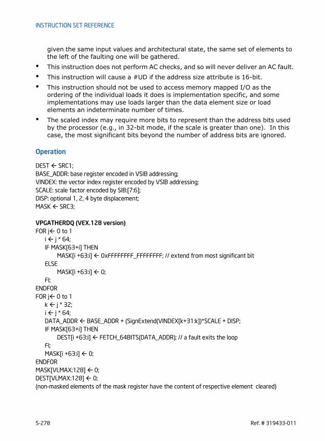
INSTRUCTION SET REFERENCE
given the same input values and architectural state, the same set of elements to the left of the faulting one will be gathered.
• This instruction does not perform AC checks, and so will never deliver an AC fault.• This instruction will cause a #UD if the address size attribute is 16-bit.• This instruction should not be used to access memory mapped I/O as the
ordering of the individual loads it does is implementation specific, and some implementations may use loads larger than the data element size or load elements an indeterminate number of times.
• The scaled index may require more bits to represent than the address bits used by the processor (e.g., in 32-bit mode, if the scale is greater than one). In this case, the most significant bits beyond the number of address bits are ignored.
Operation
DEST SRC1;BASE_ADDR: base register encoded in VSIB addressing;VINDEX: the vector index register encoded by VSIB addressing;SCALE: scale factor encoded by SIB:[7:6];DISP: optional 1, 2, 4 byte displacement;MASK SRC3;
VPGATHERDQ (VEX.128 version)FOR j 0 to 1
i j * 64;IF MASK[63+i] THEN
MASK[i +63:i] 0xFFFFFFFF_FFFFFFFF; // extend from most significant bitELSE
MASK[i +63:i] 0;FI;
ENDFORFOR j 0 to 1
k j * 32;i j * 64;DATA_ADDR BASE_ADDR + (SignExtend(VINDEX[k+31:k])*SCALE + DISP;IF MASK[63+i] THEN
DEST[i +63:i] FETCH_64BITS(DATA_ADDR); // a fault exits the loopFI;MASK[i +63:i] 0;
ENDFORMASK[VLMAX:128] 0;DEST[VLMAX:128] 0;(non-masked elements of the mask register have the content of respective element cleared)
5-278 Ref. # 319433-011

INSTRUCTION SET REFERENCE
VPGATHERQQ (VEX.128 version)FOR j 0 to 1
i j * 64;IF MASK[63+i] THEN
MASK[i +63:i] 0xFFFFFFFF_FFFFFFFF; // extend from most significant bitELSE
MASK[i +63:i] 0;FI;
ENDFORFOR j 0 to 1
i j * 64;DATA_ADDR BASE_ADDR + (SignExtend(VINDEX1[i+63:i])*SCALE + DISP;IF MASK[63+i] THEN
DEST[i +63:i] FETCH_64BITS(DATA_ADDR); // a fault exits the loopFI;MASK[i +63:i] 0;
ENDFORMASK[VLMAX:128] 0;DEST[VLMAX:128] 0;(non-masked elements of the mask register have the content of respective element cleared)
VPGATHERQQ (VEX.256 version)FOR j 0 to 3
i j * 64;IF MASK[63+i] THEN
MASK[i +63:i] 0xFFFFFFFF_FFFFFFFF; // extend from most significant bitELSE
MASK[i +63:i] 0;FI;
ENDFORFOR j 0 to 3
i j * 64;DATA_ADDR BASE_ADDR + (SignExtend(VINDEX1[i+63:i])*SCALE + DISP;IF MASK[63+i] THEN
DEST[i +63:i] FETCH_64BITS(DATA_ADDR); // a fault exits the loopFI;MASK[i +63:i] 0;
ENDFOR(non-masked elements of the mask register have the content of respective element cleared)
VPGATHERDQ (VEX.256 version)FOR j 0 to 3
i j * 64;
Ref. # 319433-011 5-279
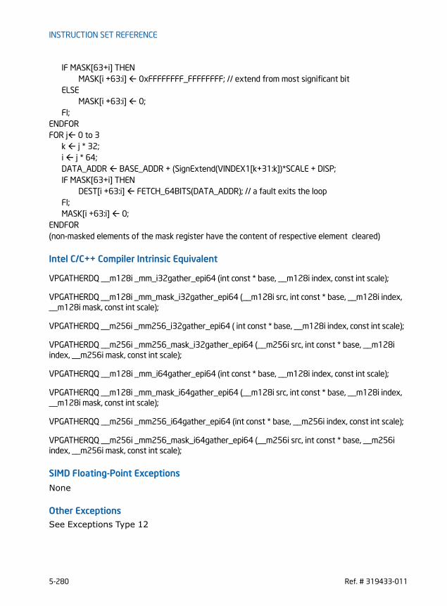
INSTRUCTION SET REFERENCE
IF MASK[63+i] THENMASK[i +63:i] 0xFFFFFFFF_FFFFFFFF; // extend from most significant bit
ELSEMASK[i +63:i] 0;
FI;ENDFORFOR j 0 to 3
k j * 32;i j * 64;DATA_ADDR BASE_ADDR + (SignExtend(VINDEX1[k+31:k])*SCALE + DISP;IF MASK[63+i] THEN
DEST[i +63:i] FETCH_64BITS(DATA_ADDR); // a fault exits the loopFI;MASK[i +63:i] 0;
ENDFOR(non-masked elements of the mask register have the content of respective element cleared)
Intel C/C++ Compiler Intrinsic Equivalent
VPGATHERDQ __m128i _mm_i32gather_epi64 (int const * base, __m128i index, const int scale);
VPGATHERDQ __m128i _mm_mask_i32gather_epi64 (__m128i src, int const * base, __m128i index, __m128i mask, const int scale);
VPGATHERDQ __m256i _mm256_i32gather_epi64 ( int const * base, __m128i index, const int scale);
VPGATHERDQ __m256i _mm256_mask_i32gather_epi64 (__m256i src, int const * base, __m128i index, __m256i mask, const int scale);
VPGATHERQQ __m128i _mm_i64gather_epi64 (int const * base, __m128i index, const int scale);
VPGATHERQQ __m128i _mm_mask_i64gather_epi64 (__m128i src, int const * base, __m128i index, __m128i mask, const int scale);
VPGATHERQQ __m256i _mm256_i64gather_epi64 (int const * base, __m256i index, const int scale);
VPGATHERQQ __m256i _mm256_mask_i64gather_epi64 (__m256i src, int const * base, __m256i index, __m256i mask, const int scale);
SIMD Floating-Point Exceptions
None
Other ExceptionsSee Exceptions Type 12
5-280 Ref. # 319433-011

INSTRUCTION SET REFERENCE - FMA
CHAPTER 6INSTRUCTION SET REFERENCE - FMA
6.1 FMA INSTRUCTION SET REFERENCEThis section describes FMA instructions in details. Conventions and notations of instruction format can be found in Section 5.1.
Ref. # 319433-011 6-1

INSTRUCTION SET REFERENCE - FMA
VFMADD132PD/VFMADD213PD/VFMADD231PD - Fused Multiply-Add of Packed Double-Precision Floating-Point Values
Instruction Operand Encoding
Description
Performs a set of SIMD multiply-add computation on packed double-precision floating-point values using three source operands and writes the multiply-add results
Opcode/Instruction
Op/ En
64/32-bit Mode
CPUID Feature Flag
Description
VEX.DDS.128.66.0F38.W1 98 /r A V/V FMA Multiply packed double-precision floating-point values from xmm0 and xmm2/mem, add to xmm1 and put result in xmm0.
VFMADD132PD xmm0, xmm1, xmm2/m128
VEX.DDS.128.66.0F38.W1 A8 /r
A V/V FMA Multiply packed double-precision floating-point values from xmm0 and xmm1, add to xmm2/mem and put result in xmm0.
VFMADD213PD xmm0, xmm1, xmm2/m128
VEX.DDS.128.66.0F38.W1 B8 /r
A V/V FMA Multiply packed double-precision floating-point values from xmm1 and xmm2/mem, add to xmm0 and put result in xmm0.
VFMADD231PD xmm0, xmm1, xmm2/m128
VEX.DDS.256.66.0F38.W1 98 /r A V/V FMA Multiply packed double-precision floating-point values from ymm0 and ymm2/mem, add to ymm1 and put result in ymm0.
VFMADD132PD ymm0, ymm1, ymm2/m256
VEX.DDS.256.66.0F38.W1 A8 /r
A V/V FMA Multiply packed double-precision floating-point values from ymm0 and ymm1, add to ymm2/mem and put result in ymm0.
VFMADD213PD ymm0, ymm1, ymm2/m256
VEX.DDS.256.66.0F38.W1 B8 /r
A V/V FMA Multiply packed double-precision floating-point values from ymm1 and ymm2/mem, add to ymm0 and put result in ymm0.
VFMADD231PD ymm0, ymm1, ymm2/m256
Op/En Operand 1 Operand 2 Operand 3 Operand 4
A ModRM:reg (r, w) VEX.vvvv (r) ModRM:r/m (r) NA
6-2 Ref. # 319433-011

INSTRUCTION SET REFERENCE - FMA
in the destination operand. The destination operand is also the first source operand. The second operand must be a SIMD register. The third source operand can be a SIMD register or a memory location. VFMADD132PD: Multiplies the two or four packed double-precision floating-point values from the first source operand to the two or four packed double-precision floating-point values in the third source operand, adds the infinite precision interme-diate result to the two or four packed double-precision floating-point values in the second source operand, performs rounding and stores the resulting two or four packed double-precision floating-point values to the destination operand (first source operand).VFMADD213PD: Multiplies the two or four packed double-precision floating-point values from the second source operand to the two or four packed double-precision floating-point values in the first source operand, adds the infinite precision interme-diate result to the two or four packed double-precision floating-point values in the third source operand, performs rounding and stores the resulting two or four packed double-precision floating-point values to the destination operand (first source operand).VFMADD231PD: Multiplies the two or four packed double-precision floating-point values from the second source to the two or four packed double-precision floating-point values in the third source operand, adds the infinite precision intermediate result to the two or four packed double-precision floating-point values in the first source operand, performs rounding and stores the resulting two or four packed double-precision floating-point values to the destination operand (first source operand).VEX.256 encoded version: The destination operand (also first source operand) is a YMM register and encoded in reg_field. The second source operand is a YMM register and encoded in VEX.vvvv. The third source operand is a YMM register or a 256-bit memory location and encoded in rm_field. VEX.128 encoded version: The destination operand (also first source operand) is a XMM register and encoded in reg_field. The second source operand is a XMM register and encoded in VEX.vvvv. The third source operand is a XMM register or a 128-bit memory location and encoded in rm_field. The upper 128 bits of the YMM destination register are zeroed.Compiler tools may optionally support a complementary mnemonic for each instruc-tion mnemonic listed in the opcode/instruction column of the summary table. The behavior of the complementary mnemonic in situations involving NANs are governed by the definition of the instruction mnemonic defined in the opcode/instruction column. See also Section 2.3.1, “FMA Instruction Operand Order and Arithmetic Behavior”.
Operation
In the operations below, “+” and “*” symbols represent multiplication and addition with infinite precision inputs and outputs (no rounding).
Ref. # 319433-011 6-3

INSTRUCTION SET REFERENCE - FMA
VFMADD132PD DEST, SRC2, SRC3 IF (VEX.128) THEN
MAXVL =2ELSEIF (VEX.256)
MAXVL = 4FIFor i = 0 to MAXVL-1 {
n = 64*i;DEST[n+63:n] RoundFPControl_MXCSR(DEST[n+63:n]*SRC3[n+63:n] + SRC2[n+63:n])
}IF (VEX.128) THENDEST[VLMAX-1:128] 0FI
VFMADD213PD DEST, SRC2, SRC3 IF (VEX.128) THEN
MAXVL =2ELSEIF (VEX.256)
MAXVL = 4FIFor i = 0 to MAXVL-1 {
n = 64*i;DEST[n+63:n] RoundFPControl_MXCSR(SRC2[n+63:n]*DEST[n+63:n] + SRC3[n+63:n])
}IF (VEX.128) THENDEST[VLMAX-1:128] 0FI
VFMADD231PD DEST, SRC2, SRC3 IF (VEX.128) THEN
MAXVL =2ELSEIF (VEX.256)
MAXVL = 4FIFor i = 0 to MAXVL-1 {
n = 64*i;DEST[n+63:n] RoundFPControl_MXCSR(SRC2[n+63:n]*SRC3[n+63:n] + DEST[n+63:n])
}IF (VEX.128) THENDEST[VLMAX-1:128] 0FI
6-4 Ref. # 319433-011

INSTRUCTION SET REFERENCE - FMA
Intel C/C++ Compiler Intrinsic Equivalent
VFMADD132PD __m128d _mm_fmadd_pd (__m128d a, __m128d b, __m128d c);
VFMADD213PD __m128d _mm_fmadd_pd (__m128d a, __m128d b, __m128d c);
VFMADD231PD __m128d _mm_fmadd_pd (__m128d a, __m128d b, __m128d c);
VFMADD132PD __m256d _mm256_fmadd_pd (__m256d a, __m256d b, __m256d c);
VFMADD213PD __m256d _mm256_fmadd_pd (__m256d a, __m256d b, __m256d c);
VFMADD231PD __m256d _mm256_fmadd_pd (__m256d a, __m256d b, __m256d c);
SIMD Floating-Point Exceptions
Overflow, Underflow, Invalid, Precision, Denormal
Other ExceptionsSee Exceptions Type 2
Ref. # 319433-011 6-5

INSTRUCTION SET REFERENCE - FMA
VFMADD132PS/VFMADD213PS/VFMADD231PS - Fused Multiply-Add of Packed Single-Precision Floating-Point Values
Opcode/Instruction
Op/ En
64/32-bit Mode
CPUID Feature Flag
Description
VEX.DDS.128.66.0F38.W0 98 /r A V/V FMA Multiply packed single-precision floating-point values from xmm0 and xmm2/mem, add to xmm1 and put result in xmm0.
VFMADD132PS xmm0, xmm1, xmm2/m128
VEX.DDS.128.66.0F38.W0 A8 /r A V/V FMA Multiply packed single-precision floating-point values from xmm0 and xmm1, add to xmm2/mem and put result in xmm0.
VFMADD213PS xmm0, xmm1, xmm2/m128
VEX.DDS.128.66.0F38.W0 B8 /r A V/V FMA Multiply packed single-precision floating-point values from xmm1 and xmm2/mem, add to xmm0 and put result in xmm0.
VFMADD231PS xmm0, xmm1, xmm2/m128
VEX.DDS.256.66.0F38.W0 98 /r A V/V FMA Multiply packed single-precision floating-point values from ymm0 and ymm2/mem, add to ymm1 and put result in ymm0.
VFMADD132PS ymm0, ymm1, ymm2/m256
VEX.DDS.256.66.0F38.W0 A8 /r A V/V FMA Multiply packed single-precision floating-point values from ymm0 and ymm1, add to ymm2/mem and put result in ymm0.
VFMADD213PS ymm0, ymm1, ymm2/m256
VEX.DDS.256.66.0F38.0 B8 /r A V/V FMA Multiply packed single-precision floating-point values from ymm1 and ymm2/mem, add to ymm0 and put result in ymm0.
VFMADD231PS ymm0, ymm1, ymm2/m256
6-6 Ref. # 319433-011

INSTRUCTION SET REFERENCE - FMA
Instruction Operand Encoding
Description
Performs a set of SIMD multiply-add computation on packed single-precision floating-point values using three source operands and writes the multiply-add results in the destination operand. The destination operand is also the first source operand. The second operand must be a SIMD register. The third source operand can be a SIMD register or a memory location. VFMADD132PS: Multiplies the four or eight packed single-precision floating-point values from the first source operand to the four or eight packed single-precision floating-point values in the third source operand, adds the infinite precision interme-diate result to the four or eight packed single-precision floating-point values in the second source operand, performs rounding and stores the resulting four or eight packed single-precision floating-point values to the destination operand (first source operand).VFMADD213PS: Multiplies the four or eight packed single-precision floating-point values from the second source operand to the four or eight packed single-precision floating-point values in the first source operand, adds the infinite precision interme-diate result to the four or eight packed single-precision floating-point values in the third source operand, performs rounding and stores the resulting the four or eight packed single-precision floating-point values to the destination operand (first source operand).VFMADD231PS: Multiplies the four or eight packed single-precision floating-point values from the second source operand to the four or eight packed single-precision floating-point values in the third source operand, adds the infinite precision interme-diate result to the four or eight packed single-precision floating-point values in the first source operand, performs rounding and stores the resulting four or eight packed single-precision floating-point values to the destination operand (first source operand).VEX.256 encoded version: The destination operand (also first source operand) is a YMM register and encoded in reg_field. The second source operand is a YMM register and encoded in VEX.vvvv. The third source operand is a YMM register or a 256-bit memory location and encoded in rm_field. VEX.128 encoded version: The destination operand (also first source operand) is a XMM register and encoded in reg_field. The second source operand is a XMM register and encoded in VEX.vvvv. The third source operand is a XMM register or a 128-bit memory location and encoded in rm_field. The upper 128 bits of the YMM destination register are zeroed.Compiler tools may optionally support a complementary mnemonic for each instruc-tion mnemonic listed in the opcode/instruction column of the summary table. The behavior of the complementary mnemonic in situations involving NANs are governed
Op/En Operand 1 Operand 2 Operand 3 Operand 4
A ModRM:reg (r, w) VEX.vvvv (r) ModRM:r/m (r) NA
Ref. # 319433-011 6-7

INSTRUCTION SET REFERENCE - FMA
by the definition of the instruction mnemonic defined in the opcode/instruction column. See also Section 2.3.1, “FMA Instruction Operand Order and Arithmetic Behavior”
Operation
In the operations below, “+” and “*” symbols represent multiplication and addition with infinite precision inputs and outputs (no rounding).
VFMADD132PS DEST, SRC2, SRC3 IF (VEX.128) THEN
MAXVL =4ELSEIF (VEX.256)
MAXVL = 8FIFor i = 0 to MAXVL-1 {
n = 32*i;DEST[n+31:n] RoundFPControl_MXCSR(DEST[n+31:n]*SRC3[n+31:n] + SRC2[n+31:n])
}IF (VEX.128) THEN
DEST[VLMAX-1:128] 0FI
VFMADD213PS DEST, SRC2, SRC3 IF (VEX.128) THEN
MAXVL =4ELSEIF (VEX.256)
MAXVL = 8FIFor i = 0 to MAXVL-1 {
n = 32*i;DEST[n+31:n] RoundFPControl_MXCSR(SRC2[n+31:n]*DEST[n+31:n] + SRC3[n+31:n])
}IF (VEX.128) THEN
DEST[VLMAX-1:128] 0FI
VFMADD231PS DEST, SRC2, SRC3 IF (VEX.128) THEN
MAXVL =4ELSEIF (VEX.256)
MAXVL = 8FIFor i = 0 to MAXVL-1 {
6-8 Ref. # 319433-011

INSTRUCTION SET REFERENCE - FMA
n = 32*i;DEST[n+31:n] RoundFPControl_MXCSR(SRC2[n+31:n]*SRC3[n+31:n] + DEST[n+31:n])
}IF (VEX.128) THEN
DEST[VLMAX-1:128] 0FI
Intel C/C++ Compiler Intrinsic Equivalent
VFMADD132PS __m128 _mm_fmadd_ps (__m128 a, __m128 b, __m128 c);
VFMADD213PS __m128 _mm_fmadd_ps (__m128 a, __m128 b, __m128 c);
VFMADD231PS __m128 _mm_fmadd_ps (__m128 a, __m128 b, __m128 c);
VFMADD132PS __m256 _mm256_fmadd_ps (__m256 a, __m256 b, __m256 c);
VFMADD213PS __m256 _mm256_fmadd_ps (__m256 a, __m256 b, __m256 c);
VFMADD231PS __m256 _mm256_fmadd_ps (__m256 a, __m256 b, __m256 c);
SIMD Floating-Point Exceptions
Overflow, Underflow, Invalid, Precision, Denormal
Other ExceptionsSee Exceptions Type 2
Ref. # 319433-011 6-9

INSTRUCTION SET REFERENCE - FMA
VFMADD132SD/VFMADD213SD/VFMADD231SD - Fused Multiply-Add of Scalar Double-Precision Floating-Point Values
Instruction Operand Encoding
Description
Performs a SIMD multiply-add computation on the low packed double-precision floating-point values using three source operands and writes the multiply-add result in the destination operand. The destination operand is also the first source operand. The second operand must be a SIMD register. The third source operand can be a SIMD register or a memory location. VFMADD132SD: Multiplies the low packed double-precision floating-point value from the first source operand to the low packed double-precision floating-point value in the third source operand, adds the infinite precision intermediate result to the low packed double-precision floating-point values in the second source operand, performs rounding and stores the resulting packed double-precision floating-point value to the destination operand (first source operand).VFMADD213SD: Multiplies the low packed double-precision floating-point value from the second source operand to the low packed double-precision floating-point value in the first source operand, adds the infinite precision intermediate result to the low packed double-precision floating-point value in the third source operand, performs rounding and stores the resulting packed double-precision floating-point value to the destination operand (first source operand).
Opcode/Instruction
Op/ En
64/32-bit Mode
CPUID Feature Flag
Description
VEX.DDS.LIG.128.66.0F38.W1 99 /r
A V/V FMA Multiply scalar double-precision floating-point value from xmm0 and xmm2/mem, add to xmm1 and put result in xmm0.
VFMADD132SD xmm0, xmm1, xmm2/m64
VEX.DDS.LIG.128.66.0F38.W1 A9 /r
A V/V FMA Multiply scalar double-precision floating-point value from xmm0 and xmm1, add to xmm2/mem and put result in xmm0.
VFMADD213SD xmm0, xmm1, xmm2/m64
VEX.DDS.LIG.128.66.0F38.W1 B9 /r
A V/V FMA Multiply scalar double-precision floating-point value from xmm1 and xmm2/mem, add to xmm0 and put result in xmm0.
VFMADD231SD xmm0, xmm1, xmm2/m64
Op/En Operand 1 Operand 2 Operand 3 Operand 4
A ModRM:reg (r, w) VEX.vvvv (r) ModRM:r/m (r) NA
6-10 Ref. # 319433-011

INSTRUCTION SET REFERENCE - FMA
VFMADD231SD: Multiplies the low packed double-precision floating-point value from the second source to the low packed double-precision floating-point value in the third source operand, adds the infinite precision intermediate result to the low packed double-precision floating-point value in the first source operand, performs rounding and stores the resulting packed double-precision floating-point value to the destina-tion operand (first source operand).VEX.128 encoded version: The destination operand (also first source operand) is a XMM register and encoded in reg_field. The second source operand is a XMM register and encoded in VEX.vvvv. The third source operand is a XMM register or a 64-bit memory location and encoded in rm_field. The upper bits ([255:128]) of the YMM destination register are zeroed.Compiler tools may optionally support a complementary mnemonic for each instruc-tion mnemonic listed in the opcode/instruction column of the summary table. The behavior of the complementary mnemonic in situations involving NANs are governed by the definition of the instruction mnemonic defined in the opcode/instruction column. See also Section 2.3.1, “FMA Instruction Operand Order and Arithmetic Behavior”
Operation
In the operations below, “+” and “*” symbols represent multiplication and addition with infinite precision inputs and outputs (no rounding).
VFMADD132SD DEST, SRC2, SRC3 DEST[63:0] RoundFPControl_MXCSR(DEST[63:0]*SRC3[63:0] + SRC2[63:0])DEST[127:64] DEST[127:64]DEST[VLMAX-1:128] 0
VFMADD213SD DEST, SRC2, SRC3 DEST[63:0] RoundFPControl_MXCSR(SRC2[63:0]*DEST[63:0] + SRC3[63:0])DEST[127:64] DEST[127:64]DEST[VLMAX-1:128] 0
VFMADD231SD DEST, SRC2, SRC3 DEST[63:0] RoundFPControl_MXCSR(SRC2[63:0]*SRC3[63:0] + DEST[63:0])DEST[127:64] DEST[127:64]DEST[VLMAX-1:128] 0
Intel C/C++ Compiler Intrinsic Equivalent
VFMADD132SD __m128d _mm_fmadd_sd (__m128d a, __m128d b, __m128d c);
VFMADD213SD __m128d _mm_fmadd_sd (__m128d a, __m128d b, __m128d c);
VFMADD231SD __m128d _mm_fmadd_sd (__m128d a, __m128d b, __m128d c);
Ref. # 319433-011 6-11

INSTRUCTION SET REFERENCE - FMA
SIMD Floating-Point Exceptions
Overflow, Underflow, Invalid, Precision, Denormal
Other ExceptionsSee Exceptions Type 3
6-12 Ref. # 319433-011

INSTRUCTION SET REFERENCE - FMA
VFMADD132SS/VFMADD213SS/VFMADD231SS - Fused Multiply-Add of Scalar Single-Precision Floating-Point Values
Instruction Operand Encoding
Description
Performs a SIMD multiply-add computation on packed single-precision floating-point values using three source operands and writes the multiply-add results in the desti-nation operand. The destination operand is also the first source operand. The second operand must be a SIMD register. The third source operand can be a SIMD register or a memory location. VFMADD132SS: Multiplies the low packed single-precision floating-point value from the first source operand to the low packed single-precision floating-point value in the third source operand, adds the infinite precision intermediate result to the low packed single-precision floating-point value in the second source operand, performs rounding and stores the resulting packed single-precision floating-point value to the destination operand (first source operand).VFMADD213SS: Multiplies the low packed single-precision floating-point value from the second source operand to the low packed single-precision floating-point value in the first source operand, adds the infinite precision intermediate result to the low packed single-precision floating-point value in the third source operand, performs rounding and stores the resulting packed single-precision floating-point value to the destination operand (first source operand).
Opcode/Instruction
Op/ En
64/32-bit Mode
CPUID Feature Flag
Description
VEX.DDS.LIG.128.66.0F38.W0 99 /r
A V/V FMA Multiply scalar single-precision floating-point value from xmm0 and xmm2/mem, add to xmm1 and put result in xmm0.
VFMADD132SS xmm0, xmm1, xmm2/m32
VEX.DDS.LIG.128.66.0F38.W0 A9 /r
A V/V FMA Multiply scalar single-precision floating-point value from xmm0 and xmm1, add to xmm2/mem and put result in xmm0.
VFMADD213SS xmm0, xmm1, xmm2/m32
VEX.DDS.LIG.128.66.0F38.W0 B9 /r
A V/V FMA Multiply scalar single-precision floating-point value from xmm1 and xmm2/mem, add to xmm0 and put result in xmm0.
VFMADD231SS xmm0, xmm1, xmm2/m32
Op/En Operand 1 Operand 2 Operand 3 Operand 4
A ModRM:reg (r, w) VEX.vvvv (r) ModRM:r/m (r) NA
Ref. # 319433-011 6-13

INSTRUCTION SET REFERENCE - FMA
VFMADD231SS: Multiplies the low packed single-precision floating-point value from the second source operand to the low packed single-precision floating-point value in the third source operand, adds the infinite precision intermediate result to the low packed single-precision floating-point value in the first source operand, performs rounding and stores the resulting packed single-precision floating-point value to the destination operand (first source operand).VEX.128 encoded version: The destination operand (also first source operand) is a XMM register and encoded in reg_field. The second source operand is a XMM register and encoded in VEX.vvvv. The third source operand is a XMM register or a 32-bit memory location and encoded in rm_field. The upper bits ([255:128]) of the YMM destination register are zeroed.Compiler tools may optionally support a complementary mnemonic for each instruc-tion mnemonic listed in the opcode/instruction column of the summary table. The behavior of the complementary mnemonic in situations involving NANs are governed by the definition of the instruction mnemonic defined in the opcode/instruction column. See also Section 2.3.1, “FMA Instruction Operand Order and Arithmetic Behavior”
Operation
In the operations below, “+” and “*” symbols represent multiplication and addition with infinite precision inputs and outputs (no rounding).
VFMADD132SS DEST, SRC2, SRC3 DEST[31:0] RoundFPControl_MXCSR(DEST[31:0]*SRC3[31:0] + SRC2[31:0])DEST[127:32] DEST[127:32]DEST[VLMAX-1:128] 0
VFMADD213SS DEST, SRC2, SRC3 DEST[31:0] RoundFPControl_MXCSR(SRC2[31:0]*DEST[31:0] + SRC3[31:0])DEST[127:32] DEST[127:32]DEST[VLMAX-1:128] 0
VFMADD231SS DEST, SRC2, SRC3 DEST[31:0] RoundFPControl_MXCSR(SRC2[31:0]*SRC3[63:0] + DEST[31:0])DEST[127:32] DEST[127:32]DEST[VLMAX-1:128] 0
Intel C/C++ Compiler Intrinsic Equivalent
VFMADD132SS __m128 _mm_fmadd_ss (__m128 a, __m128 b, __m128 c);
VFMADD213SS __m128 _mm_fmadd_ss (__m128 a, __m128 b, __m128 c);
VFMADD231SS __m128 _mm_fmadd_ss (__m128 a, __m128 b, __m128 c);
6-14 Ref. # 319433-011

INSTRUCTION SET REFERENCE - FMA
SIMD Floating-Point Exceptions
Overflow, Underflow, Invalid, Precision, Denormal
Other ExceptionsSee Exceptions Type 3
Ref. # 319433-011 6-15

INSTRUCTION SET REFERENCE - FMA
VFMADDSUB132PD/VFMADDSUB213PD/VFMADDSUB231PD - Fused Multiply-Alternating Add/Subtract of Packed Double-Precision Floating-Point Values
Opcode/Instruction
Op/ En
64/32-bit Mode
CPUID Feature Flag
Description
VEX.DDS.128.66.0F38.W1 96 /r A V/V FMA Multiply packed double-precision floating-point values from xmm0 and xmm2/mem, add/subtract elements in xmm1 and put result in xmm0.
VFMADDSUB132PD xmm0, xmm1, xmm2/m128
VEX.DDS.128.66.0F38.W1 A6 /r
A V/V FMA Multiply packed double-precision floating-point values from xmm0 and xmm1, add/subtract ele-ments in xmm2/mem and put result in xmm0.
VFMADDSUB213PD xmm0, xmm1, xmm2/m128
VEX.DDS.128.66.0F38.W1 B6 /r
A V/V FMA Multiply packed double-precision floating-point values from xmm1 and xmm2/mem, add/subtract elements in xmm0 and put result in xmm0.
VFMADDSUB231PD xmm0, xmm1, xmm2/m128
VEX.DDS.256.66.0F38.W1 96 /r A V/V FMA Multiply packed double-precision floating-point values from ymm0 and ymm2/mem, add/subtract elements in ymm1 and put result in ymm0.
VFMADDSUB132PD ymm0, ymm1, ymm2/m256
VEX.DDS.256.66.0F38.W1 A6 /r
A V/V FMA Multiply packed double-precision floating-point values from ymm0 and ymm1, add/subtract ele-ments in ymm2/mem and put result in ymm0.
VFMADDSUB213PD ymm0, ymm1, ymm2/m256
VEX.DDS.256.66.0F38.W1 B6 /r
A V/V FMA Multiply packed double-precision floating-point values from ymm1 and ymm2/mem, add/subtract elements in ymm0 and put result in ymm0.
VFMADDSUB231PD ymm0, ymm1, ymm2/m256
6-16 Ref. # 319433-011

INSTRUCTION SET REFERENCE - FMA
Instruction Operand Encoding
Description
VFMADDSUB132PD: Multiplies the two or four packed double-precision floating-point values from the first source operand to the two or four packed double-precision floating-point values in the third source operand. From the infinite precision interme-diate result, adds the odd double-precision floating-point elements and subtracts the even double-precision floating-point values in the second source operand, performs rounding and stores the resulting two or four packed double-precision floating-point values to the destination operand (first source operand).VFMADDSUB213PD: Multiplies the two or four packed double-precision floating-point values from the second source operand to the two or four packed double-precision floating-point values in the first source operand. From the infinite precision interme-diate result, adds the odd double-precision floating-point elements and subtracts the even double-precision floating-point values in the third source operand, performs rounding and stores the resulting two or four packed double-precision floating-point values to the destination operand (first source operand).VFMADDSUB231PD: Multiplies the two or four packed double-precision floating-point values from the second source operand to the two or four packed double-precision floating-point values in the third source operand. From the infinite precision interme-diate result, adds the odd double-precision floating-point elements and subtracts the even double-precision floating-point values in the first source operand, performs rounding and stores the resulting two or four packed double-precision floating-point values to the destination operand (first source operand).VEX.256 encoded version: The destination operand (also first source operand) is a YMM register and encoded in reg_field. The second source operand is a YMM register and encoded in VEX.vvvv. The third source operand is a YMM register or a 256-bit memory location and encoded in rm_field. VEX.128 encoded version: The destination operand (also first source operand) is a XMM register and encoded in reg_field. The second source operand is a XMM register and encoded in VEX.vvvv. The third source operand is a XMM register or a 128-bit memory location and encoded in rm_field. The upper 128 bits of the YMM destination register are zeroed.Compiler tools may optionally support a complementary mnemonic for each instruc-tion mnemonic listed in the opcode/instruction column of the summary table. The behavior of the complementary mnemonic in situations involving NANs are governed by the definition of the instruction mnemonic defined in the opcode/instruction column. See also Section 2.3.1, “FMA Instruction Operand Order and Arithmetic Behavior”
Op/En Operand 1 Operand 2 Operand 3 Operand 4
A ModRM:reg (r, w) VEX.vvvv (r) ModRM:r/m (r) NA
Ref. # 319433-011 6-17

INSTRUCTION SET REFERENCE - FMA
Operation
In the operations below, “+” and “*” symbols represent multiplication and addition with infinite precision inputs and outputs (no rounding).
VFMADDSUB132PD DEST, SRC2, SRC3 IF (VEX.128) THEN
DEST[63:0] RoundFPControl_MXCSR(DEST[63:0]*SRC3[63:0] - SRC2[63:0])DEST[127:64] RoundFPControl_MXCSR(DEST[127:64]*SRC3[127:64] + SRC2[127:64])DEST[VLMAX-1:128] 0
ELSEIF (VEX.256)DEST[63:0] RoundFPControl_MXCSR(DEST[63:0]*SRC3[63:0] - SRC2[63:0])DEST[127:64] RoundFPControl_MXCSR(DEST[127:64]*SRC3[127:64] + SRC2[127:64])DEST[191:128] RoundFPControl_MXCSR(DEST[191:128]*SRC3[191:128] - SRC2[191:128])DEST[255:192] RoundFPControl_MXCSR(DEST[255:192]*SRC3[255:192] + SRC2[255:192]
FI
VFMADDSUB213PD DEST, SRC2, SRC3 IF (VEX.128) THEN
DEST[63:0] RoundFPControl_MXCSR(SRC2[63:0]*DEST[63:0] - SRC3[63:0])DEST[127:64] RoundFPControl_MXCSR(SRC2[127:64]*DEST[127:64] + SRC3[127:64])DEST[VLMAX-1:128] 0
ELSEIF (VEX.256)DEST[63:0] RoundFPControl_MXCSR(SRC2[63:0]*DEST[63:0] - SRC3[63:0])DEST[127:64] RoundFPControl_MXCSR(SRC2[127:64]*DEST[127:64] + SRC3[127:64])DEST[191:128] RoundFPControl_MXCSR(SRC2[191:128]*DEST[191:128] - SRC3[191:128])DEST[255:192] RoundFPControl_MXCSR(SRC2[255:192]*DEST[255:192] + SRC3[255:192]
FI
VFMADDSUB231PD DEST, SRC2, SRC3 IF (VEX.128) THEN
DEST[63:0] RoundFPControl_MXCSR(SRC2[63:0]*SRC3[63:0] - DEST[63:0])DEST[127:64] RoundFPControl_MXCSR(SRC2[127:64]*SRC3[127:64] + DEST[127:64])DEST[VLMAX-1:128] 0
ELSEIF (VEX.256)DEST[63:0] RoundFPControl_MXCSR(SRC2[63:0]*SRC3[63:0] - DEST[63:0])DEST[127:64] RoundFPControl_MXCSR(SRC2[127:64]*SRC3[127:64] + DEST[127:64])DEST[191:128] RoundFPControl_MXCSR(SRC2[191:128]*SRC3[191:128] - DEST[191:128])DEST[255:192] RoundFPControl_MXCSR(SRC2[255:192]*SRC3[255:192] + DEST[255:192]
FI
Intel C/C++ Compiler Intrinsic Equivalent
VFMADDSUB132PD __m128d _mm_fmaddsub_pd (__m128d a, __m128d b, __m128d c);
6-18 Ref. # 319433-011
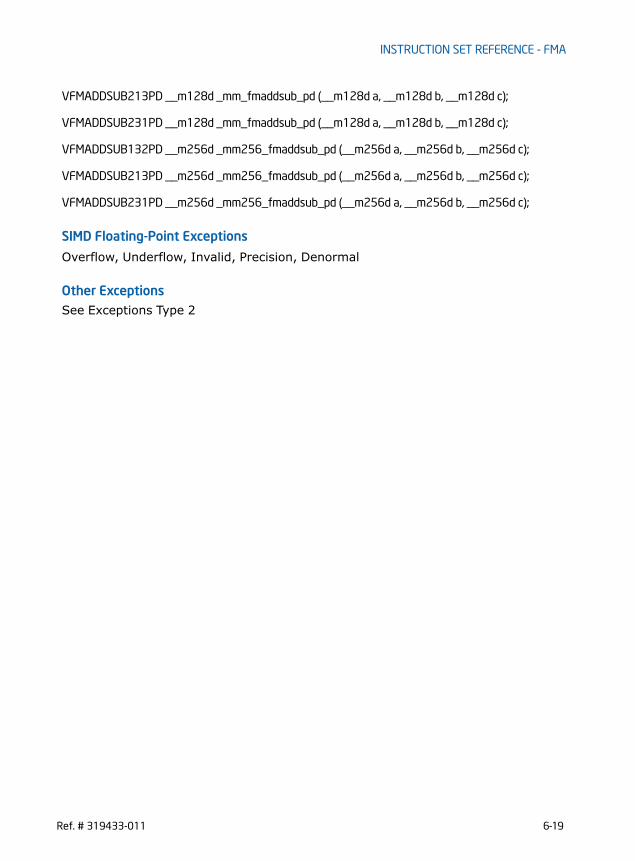
INSTRUCTION SET REFERENCE - FMA
VFMADDSUB213PD __m128d _mm_fmaddsub_pd (__m128d a, __m128d b, __m128d c);
VFMADDSUB231PD __m128d _mm_fmaddsub_pd (__m128d a, __m128d b, __m128d c);
VFMADDSUB132PD __m256d _mm256_fmaddsub_pd (__m256d a, __m256d b, __m256d c);
VFMADDSUB213PD __m256d _mm256_fmaddsub_pd (__m256d a, __m256d b, __m256d c);
VFMADDSUB231PD __m256d _mm256_fmaddsub_pd (__m256d a, __m256d b, __m256d c);
SIMD Floating-Point Exceptions
Overflow, Underflow, Invalid, Precision, Denormal
Other ExceptionsSee Exceptions Type 2
Ref. # 319433-011 6-19

INSTRUCTION SET REFERENCE - FMA
VFMADDSUB132PS/VFMADDSUB213PS/VFMADDSUB231PS - Fused Multiply-Alternating Add/Subtract of Packed Single-Precision Floating-Point Values
Instruction Operand Encoding
Opcode/Instruction
Op/ En
64/32-bit Mode
CPUID Feature Flag
Description
VEX.DDS.128.66.0F38.W0 96 /r
A V/V FMA Multiply packed single-precision floating-point values from xmm0 and xmm2/mem, add/subtract elements in xmm1 and put result in xmm0.
VFMADDSUB132PS xmm0, xmm1, xmm2/m128
VEX.DDS.128.66.0F38.W0 A6 /r
A V/V FMA Multiply packed single-precision floating-point values from xmm0 and xmm1, add/subtract elements in xmm2/mem and put result in xmm0.
VFMADDSUB213PS xmm0, xmm1, xmm2/m128
VEX.DDS.128.66.0F38.W0 B6 /r
A V/V FMA Multiply packed single-precision floating-point values from xmm1 and xmm2/mem, add/subtract elements in xmm0 and put result in xmm0.
VFMADDSUB231PS xmm0, xmm1, xmm2/m128
VEX.DDS.256.66.0F38.W0 96 /r
A V/V FMA Multiply packed single-precision floating-point values from ymm0 and ymm2/mem, add/subtract elements in ymm1 and put result in ymm0.
VFMADDSUB132PS ymm0, ymm1, ymm2/m256
VEX.DDS.256.66.0F38.W0 A6 /r
A V/V FMA Multiply packed single-precision floating-point values from ymm0 and ymm1, add/subtract elements in ymm2/mem and put result in ymm0.
VFMADDSUB213PS ymm0, ymm1, ymm2/m256
VEX.DDS.256.66.0F38.W0 B6 /r
A V/V FMA Multiply packed single-precision floating-point values from ymm1 and ymm2/mem, add/subtract elements in ymm0 and put result in ymm0.
VFMADDSUB231PS ymm0, ymm1, ymm2/m256
Op/En Operand 1 Operand 2 Operand 3 Operand 4
A ModRM:reg (r, w) VEX.vvvv (r) ModRM:r/m (r) NA
6-20 Ref. # 319433-011

INSTRUCTION SET REFERENCE - FMA
Description
VFMADDSUB132PS: Multiplies the four or eight packed single-precision floating-point values from the first source operand to the four or eight packed single-precision floating-point values in the third source operand. From the infinite precision interme-diate result, adds the odd single-precision floating-point elements and subtracts the even single-precision floating-point values in the second source operand, performs rounding and stores the resulting four or eight packed single-precision floating-point values to the destination operand (first source operand).VFMADDSUB213PS: Multiplies the four or eight packed single-precision floating-point values from the second source operand to the four or eight packed single-preci-sion floating-point values in the first source operand. From the infinite precision intermediate result, adds the odd single-precision floating-point elements and subtracts the even single-precision floating-point values in the third source operand, performs rounding and stores the resulting four or eight packed single-precision floating-point values to the destination operand (first source operand).VFMADDSUB231PS: Multiplies the four or eight packed single-precision floating-point values from the second source operand to the four or eight packed single-preci-sion floating-point values in the third source operand. From the infinite precision intermediate result, adds the odd single-precision floating-point elements and subtracts the even single-precision floating-point values in the first source operand, performs rounding and stores the resulting four or eight packed single-precision floating-point values to the destination operand (first source operand).VEX.256 encoded version: The destination operand (also first source operand) is a YMM register and encoded in reg_field. The second source operand is a YMM register and encoded in VEX.vvvv. The third source operand is a YMM register or a 256-bit memory location and encoded in rm_field. VEX.128 encoded version: The destination operand (also first source operand) is a XMM register and encoded in reg_field. The second source operand is a XMM register and encoded in VEX.vvvv. The third source operand is a XMM register or a 128-bit memory location and encoded in rm_field. The upper 128 bits of the YMM destination register are zeroed.Compiler tools may optionally support a complementary mnemonic for each instruc-tion mnemonic listed in the opcode/instruction column of the summary table. The behavior of the complementary mnemonic in situations involving NANs are governed by the definition of the instruction mnemonic defined in the opcode/instruction column. See also Section 2.3.1, “FMA Instruction Operand Order and Arithmetic Behavior”
Operation
In the operations below, “+” and “*” symbols represent multiplication and addition with infinite precision inputs and outputs (no rounding).
VFMADDSUB132PS DEST, SRC2, SRC3 IF (VEX.128) THEN
Ref. # 319433-011 6-21

INSTRUCTION SET REFERENCE - FMA
MAXVL =2ELSEIF (VEX.256)
MAXVL = 4FIFor i = 0 to MAXVL -1{
n = 64*i;DEST[n+31:n] RoundFPControl_MXCSR(DEST[n+31:n]*SRC3[n+31:n] - SRC2[n+31:n])DEST[n+63:n+32] RoundFPControl_MXCSR(DEST[n+63:n+32]*SRC3[n+63:n+32] +
SRC2[n+63:n+32])}IF (VEX.128) THEN
DEST[VLMAX-1:128] 0FI
VFMADDSUB213PS DEST, SRC2, SRC3 IF (VEX.128) THEN
MAXVL =2ELSEIF (VEX.256)
MAXVL = 4FIFor i = 0 to MAXVL -1{
n = 64*i;DEST[n+31:n] RoundFPControl_MXCSR(SRC2[n+31:n]*DEST[n+31:n] - SRC3[n+31:n])DEST[n+63:n+32] RoundFPControl_MXCSR(SRC2[n+63:n+32]*DEST[n+63:n+32] +
SRC3[n+63:n+32])}IF (VEX.128) THEN
DEST[VLMAX-1:128] 0FI
VFMADDSUB231PS DEST, SRC2, SRC3 IF (VEX.128) THEN
MAXVL =2ELSEIF (VEX.256)
MAXVL = 4FIFor i = 0 to MAXVL -1{
n = 64*i;DEST[n+31:n] RoundFPControl_MXCSR(SRC2[n+31:n]*SRC3[n+31:n] - DEST[n+31:n])DEST[n+63:n+32] RoundFPControl_MXCSR(SRC2[n+63:n+32]*SRC3[n+63:n+32] +
DEST[n+63:n+32])}IF (VEX.128) THEN
DEST[VLMAX-1:128] 0
6-22 Ref. # 319433-011

INSTRUCTION SET REFERENCE - FMA
FI
Intel C/C++ Compiler Intrinsic Equivalent
VFMADDSUB132PS __m128 _mm_fmaddsub_ps (__m128 a, __m128 b, __m128 c);
VFMADDSUB213PS __m128 _mm_fmaddsub_ps (__m128 a, __m128 b, __m128 c);
VFMADDSUB231PS __m128 _mm_fmaddsub_ps (__m128 a, __m128 b, __m128 c);
VFMADDSUB132PS __m256 _mm256_fmaddsub_ps (__m256 a, __m256 b, __m256 c);
VFMADDSUB213PS __m256 _mm256_fmaddsub_ps (__m256 a, __m256 b, __m256 c);
VFMADDSUB231PS __m256 _mm256_fmaddsub_ps (__m256 a, __m256 b, __m256 c);
SIMD Floating-Point Exceptions
Overflow, Underflow, Invalid, Precision, Denormal
Other ExceptionsSee Exceptions Type 2
Ref. # 319433-011 6-23

INSTRUCTION SET REFERENCE - FMA
VFMSUBADD132PD/VFMSUBADD213PD/VFMSUBADD231PD - Fused Multiply-Alternating Subtract/Add of Packed Double-Precision Floating-Point Values
Instruction Operand Encoding
Opcode/Instruction
Op/ En
64/32-bit Mode
CPUID Feature Flag
Description
VEX.DDS.128.66.0F38.W1 97 /r
A V/V FMA Multiply packed double-precision floating-point values from xmm0 and xmm2/mem, subtract/add elements in xmm1 and put result in xmm0.
VFMSUBADD132PD xmm0, xmm1, xmm2/m128
VEX.DDS.128.66.0F38.W1 A7 /r
A V/V FMA Multiply packed double-precision floating-point values from xmm0 and xmm1, subtract/add elements in xmm2/mem and put result in xmm0.
VFMSUBADD213PD xmm0, xmm1, xmm2/m128
VEX.DDS.128.66.0F38.W1 B7 /r
A V/V FMA Multiply packed double-precision floating-point values from xmm1 and xmm2/mem, subtract/add elements in xmm0 and put result in xmm0.
VFMSUBADD231PD xmm0, xmm1, xmm2/m128
VEX.DDS.256.66.0F38.W1 97 /r
A V/V FMA Multiply packed double-precision floating-point values from ymm0 and ymm2/mem, subtract/add elements in ymm1 and put result in ymm0.
VFMSUBADD132PD ymm0, ymm1, ymm2/m256
VEX.DDS.256.66.0F38.W1 A7 /r
A V/V FMA Multiply packed double-precision floating-point values from ymm0 and ymm1, subtract/add elements in ymm2/mem and put result in ymm0.
VFMSUBADD213PD ymm0, ymm1, ymm2/m256
VEX.DDS.256.66.0F38.W1 B7 /r
A V/V FMA Multiply packed double-precision floating-point values from ymm1 and ymm2/mem, subtract/add elements in ymm0 and put result in ymm0.
VFMSUBADD231PD ymm0, ymm1, ymm2/m256
Op/En Operand 1 Operand 2 Operand 3 Operand 4
A ModRM:reg (r, w) VEX.vvvv (r) ModRM:r/m (r) NA
6-24 Ref. # 319433-011

INSTRUCTION SET REFERENCE - FMA
Description
VFMSUBADD132PD: Multiplies the two or four packed double-precision floating-point values from the first source operand to the two or four packed double-precision floating-point values in the third source operand. From the infinite precision interme-diate result, subtracts the odd double-precision floating-point elements and adds the even double-precision floating-point values in the second source operand, performs rounding and stores the resulting two or four packed double-precision floating-point values to the destination operand (first source operand).VFMSUBADD213PD: Multiplies the two or four packed double-precision floating-point values from the second source operand to the two or four packed double-precision floating-point values in the first source operand. From the infinite precision interme-diate result, subtracts the odd double-precision floating-point elements and adds the even double-precision floating-point values in the third source operand, performs rounding and stores the resulting two or four packed double-precision floating-point values to the destination operand (first source operand).VFMSUBADD231PD: Multiplies the two or four packed double-precision floating-point values from the second source operand to the two or four packed double-precision floating-point values in the third source operand. From the infinite precision interme-diate result, subtracts the odd double-precision floating-point elements and adds the even double-precision floating-point values in the first source operand, performs rounding and stores the resulting two or four packed double-precision floating-point values to the destination operand (first source operand).VEX.256 encoded version: The destination operand (also first source operand) is a YMM register and encoded in reg_field. The second source operand is a YMM register and encoded in VEX.vvvv. The third source operand is a YMM register or a 256-bit memory location and encoded in rm_field. VEX.128 encoded version: The destination operand (also first source operand) is a XMM register and encoded in reg_field. The second source operand is a XMM register and encoded in VEX.vvvv. The third source operand is a XMM register or a 128-bit memory location and encoded in rm_field. The upper 128 bits of the YMM destination register are zeroed.Compiler tools may optionally support a complementary mnemonic for each instruc-tion mnemonic listed in the opcode/instruction column of the summary table. The behavior of the complementary mnemonic in situations involving NANs are governed by the definition of the instruction mnemonic defined in the opcode/instruction column. See also Section 2.3.1, “FMA Instruction Operand Order and Arithmetic Behavior”
Operation
In the operations below, “+” and “*” symbols represent multiplication and addition with infinite precision inputs and outputs (no rounding).
VFMSUBADD132PD DEST, SRC2, SRC3 IF (VEX.128) THEN
Ref. # 319433-011 6-25
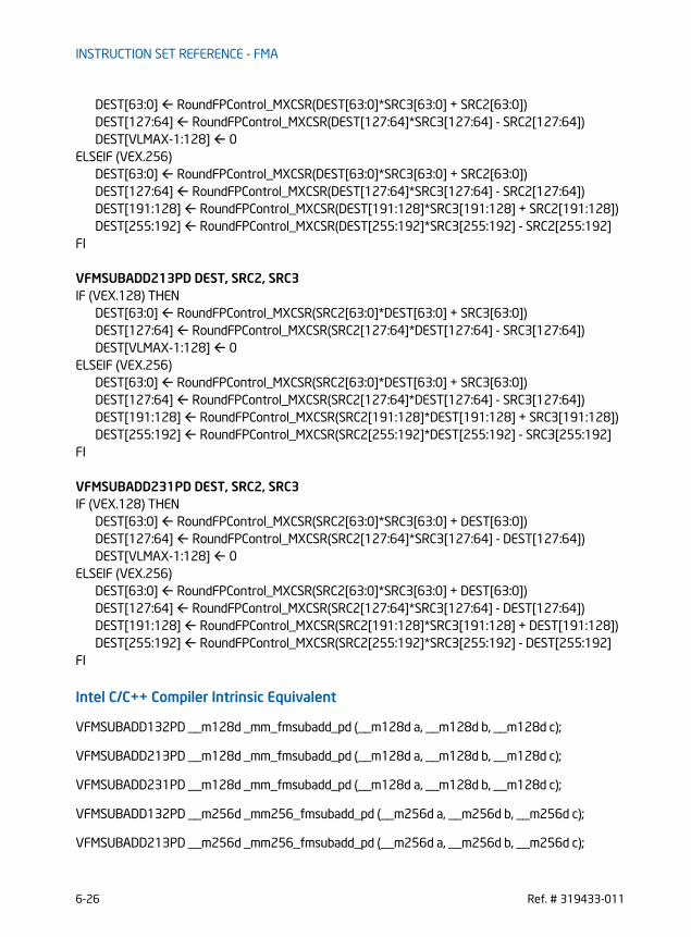
INSTRUCTION SET REFERENCE - FMA
DEST[63:0] RoundFPControl_MXCSR(DEST[63:0]*SRC3[63:0] + SRC2[63:0])DEST[127:64] RoundFPControl_MXCSR(DEST[127:64]*SRC3[127:64] - SRC2[127:64])DEST[VLMAX-1:128] 0
ELSEIF (VEX.256)DEST[63:0] RoundFPControl_MXCSR(DEST[63:0]*SRC3[63:0] + SRC2[63:0])DEST[127:64] RoundFPControl_MXCSR(DEST[127:64]*SRC3[127:64] - SRC2[127:64])DEST[191:128] RoundFPControl_MXCSR(DEST[191:128]*SRC3[191:128] + SRC2[191:128])DEST[255:192] RoundFPControl_MXCSR(DEST[255:192]*SRC3[255:192] - SRC2[255:192]
FI
VFMSUBADD213PD DEST, SRC2, SRC3 IF (VEX.128) THEN
DEST[63:0] RoundFPControl_MXCSR(SRC2[63:0]*DEST[63:0] + SRC3[63:0])DEST[127:64] RoundFPControl_MXCSR(SRC2[127:64]*DEST[127:64] - SRC3[127:64])DEST[VLMAX-1:128] 0
ELSEIF (VEX.256)DEST[63:0] RoundFPControl_MXCSR(SRC2[63:0]*DEST[63:0] + SRC3[63:0])DEST[127:64] RoundFPControl_MXCSR(SRC2[127:64]*DEST[127:64] - SRC3[127:64])DEST[191:128] RoundFPControl_MXCSR(SRC2[191:128]*DEST[191:128] + SRC3[191:128])DEST[255:192] RoundFPControl_MXCSR(SRC2[255:192]*DEST[255:192] - SRC3[255:192]
FI
VFMSUBADD231PD DEST, SRC2, SRC3 IF (VEX.128) THEN
DEST[63:0] RoundFPControl_MXCSR(SRC2[63:0]*SRC3[63:0] + DEST[63:0])DEST[127:64] RoundFPControl_MXCSR(SRC2[127:64]*SRC3[127:64] - DEST[127:64])DEST[VLMAX-1:128] 0
ELSEIF (VEX.256)DEST[63:0] RoundFPControl_MXCSR(SRC2[63:0]*SRC3[63:0] + DEST[63:0])DEST[127:64] RoundFPControl_MXCSR(SRC2[127:64]*SRC3[127:64] - DEST[127:64])DEST[191:128] RoundFPControl_MXCSR(SRC2[191:128]*SRC3[191:128] + DEST[191:128])DEST[255:192] RoundFPControl_MXCSR(SRC2[255:192]*SRC3[255:192] - DEST[255:192]
FI
Intel C/C++ Compiler Intrinsic Equivalent
VFMSUBADD132PD __m128d _mm_fmsubadd_pd (__m128d a, __m128d b, __m128d c);
VFMSUBADD213PD __m128d _mm_fmsubadd_pd (__m128d a, __m128d b, __m128d c);
VFMSUBADD231PD __m128d _mm_fmsubadd_pd (__m128d a, __m128d b, __m128d c);
VFMSUBADD132PD __m256d _mm256_fmsubadd_pd (__m256d a, __m256d b, __m256d c);
VFMSUBADD213PD __m256d _mm256_fmsubadd_pd (__m256d a, __m256d b, __m256d c);
6-26 Ref. # 319433-011

INSTRUCTION SET REFERENCE - FMA
VFMSUBADD231PD __m256d _mm256_fmsubadd_pd (__m256d a, __m256d b, __m256d c);
SIMD Floating-Point Exceptions
Overflow, Underflow, Invalid, Precision, Denormal
Other ExceptionsSee Exceptions Type 2
Ref. # 319433-011 6-27

INSTRUCTION SET REFERENCE - FMA
VFMSUBADD132PS/VFMSUBADD213PS/VFMSUBADD231PS - Fused Multiply-Alternating Subtract/Add of Packed Single-Precision Floating-Point Values
Opcode/Instruction
Op/ En
64/32-bit Mode
CPUID Feature Flag
Description
VEX.DDS.128.66.0F38.W0 97 /r
A V/V FMA Multiply packed single-precision floating-point values from xmm0 and xmm2/mem, subtract/add ele-ments in xmm1 and put result in xmm0.
VFMSUBADD132PS xmm0, xmm1, xmm2/m128
VEX.DDS.128.66.0F38.W0 A7 /r
A V/V FMA Multiply packed single-precision floating-point values from xmm0 and xmm1, subtract/add elements in xmm2/mem and put result in xmm0.
VFMSUBADD213PS xmm0, xmm1, xmm2/m128
VEX.DDS.128.66.0F38.W0 B7 /r
A V/V FMA Multiply packed single-precision floating-point values from xmm1 and xmm2/mem, subtract/add ele-ments in xmm0 and put result in xmm0.
VFMSUBADD231PS xmm0, xmm1, xmm2/m128
VEX.DDS.256.66.0F38.W0 97 /r
A V/V FMA Multiply packed single-precision floating-point values from ymm0 and ymm2/mem, subtract/add ele-ments in ymm1 and put result in ymm0.
VFMSUBADD132PS ymm0, ymm1, ymm2/m256
VEX.DDS.256.66.0F38.W0 A7 /r
A V/V FMA Multiply packed single-precision floating-point values from ymm0 and ymm1, subtract/add elements in ymm2/mem and put result in ymm0.
VFMSUBADD213PS ymm0, ymm1, ymm2/m256
VEX.DDS.256.66.0F38.W0 B7 /r
A V/V FMA Multiply packed single-precision floating-point values from ymm1 and ymm2/mem, subtract/add ele-ments in ymm0 and put result in ymm0.
VFMSUBADD231PS ymm0, ymm1, ymm2/m256
6-28 Ref. # 319433-011

INSTRUCTION SET REFERENCE - FMA
Instruction Operand Encoding
Description
VFMSUBADD132PS: Multiplies the four or eight packed single-precision floating-point values from the first source operand to the four or eight packed single-precision floating-point values in the third source operand. From the infinite precision interme-diate result, subtracts the odd single-precision floating-point elements and adds the even single-precision floating-point values in the second source operand, performs rounding and stores the resulting four or eight packed single-precision floating-point values to the destination operand (first source operand).VFMSUBADD213PS: Multiplies the four or eight packed single-precision floating-point values from the second source operand to the four or eight packed single-preci-sion floating-point values in the first source operand. From the infinite precision intermediate result, subtracts the odd single-precision floating-point elements and adds the even single-precision floating-point values in the third source operand, performs rounding and stores the resulting four or eight packed single-precision floating-point values to the destination operand (first source operand).VFMSUBADD231PS: Multiplies the four or eight packed single-precision floating-point values from the second source operand to the four or eight packed single-preci-sion floating-point values in the third source operand. From the infinite precision intermediate result, subtracts the odd single-precision floating-point elements and adds the even single-precision floating-point values in the first source operand, performs rounding and stores the resulting four or eight packed single-precision floating-point values to the destination operand (first source operand).VEX.256 encoded version: The destination operand (also first source operand) is a YMM register and encoded in reg_field. The second source operand is a YMM register and encoded in VEX.vvvv. The third source operand is a YMM register or a 256-bit memory location and encoded in rm_field. VEX.128 encoded version: The destination operand (also first source operand) is a XMM register and encoded in reg_field. The second source operand is a XMM register and encoded in VEX.vvvv. The third source operand is a XMM register or a 128-bit memory location and encoded in rm_field. The upper 128 bits of the YMM destination register are zeroed.Compiler tools may optionally support a complementary mnemonic for each instruc-tion mnemonic listed in the opcode/instruction column of the summary table. The behavior of the complementary mnemonic in situations involving NANs are governed by the definition of the instruction mnemonic defined in the opcode/instruction column. See also Section 2.3.1, “FMA Instruction Operand Order and Arithmetic Behavior”.
Op/En Operand 1 Operand 2 Operand 3 Operand 4
A ModRM:reg (r, w) VEX.vvvv (r) ModRM:r/m (r) NA
Ref. # 319433-011 6-29

INSTRUCTION SET REFERENCE - FMA
Operation
In the operations below, “+” and “*” symbols represent multiplication and addition with infinite precision inputs and outputs (no rounding).
VFMSUBADD132PS DEST, SRC2, SRC3 IF (VEX.128) THEN
MAXVL =2ELSEIF (VEX.256)
MAXVL = 4FIFor i = 0 to MAXVL -1{
n = 64*i;DEST[n+31:n] RoundFPControl_MXCSR(DEST[n+31:n]*SRC3[n+31:n] + SRC2[n+31:n])DEST[n+63:n+32] RoundFPControl_MXCSR(DEST[n+63:n+32]*SRC3[n+63:n+32] -
SRC2[n+63:n+32])}IF (VEX.128) THEN
DEST[VLMAX-1:128] 0FI
VFMSUBADD213PS DEST, SRC2, SRC3 IF (VEX.128) THEN
MAXVL =2ELSEIF (VEX.256)
MAXVL = 4FIFor i = 0 to MAXVL -1{
n = 64*i;DEST[n+31:n] RoundFPControl_MXCSR(SRC2[n+31:n]*DEST[n+31:n] +SRC3[n+31:n])DEST[n+63:n+32] RoundFPControl_MXCSR(SRC2[n+63:n+32]*DEST[n+63:n+32] -
SRC3[n+63:n+32])}IF (VEX.128) THEN
DEST[VLMAX-1:128] 0FI
VFMSUBADD231PS DEST, SRC2, SRC3 IF (VEX.128) THEN
MAXVL =2ELSEIF (VEX.256)
MAXVL = 4FIFor i = 0 to MAXVL -1{
6-30 Ref. # 319433-011

INSTRUCTION SET REFERENCE - FMA
n = 64*i;DEST[n+31:n] RoundFPControl_MXCSR(SRC2[n+31:n]*SRC3[n+31:n] + DEST[n+31:n])DEST[n+63:n+32] RoundFPControl_MXCSR(SRC2[n+63:n+32]*SRC3[n+63:n+32] -
DEST[n+63:n+32])}IF (VEX.128) THEN
DEST[VLMAX-1:128] 0FI
Intel C/C++ Compiler Intrinsic Equivalent
VFMSUBADD132PS __m128 _mm_fmsubadd_ps (__m128 a, __m128 b, __m128 c);
VFMSUBADD213PS __m128 _mm_fmsubadd_ps (__m128 a, __m128 b, __m128 c);
VFMSUBADD231PS __m128 _mm_fmsubadd_ps (__m128 a, __m128 b, __m128 c);
VFMSUBADD132PS __m256 _mm256_fmsubadd_ps (__m256 a, __m256 b, __m256 c);
VFMSUBADD213PS __m256 _mm256_fmsubadd_ps (__m256 a, __m256 b, __m256 c);
VFMSUBADD231PS __m256 _mm256_fmsubadd_ps (__m256 a, __m256 b, __m256 c);
SIMD Floating-Point Exceptions
Overflow, Underflow, Invalid, Precision, Denormal
Other ExceptionsSee Exceptions Type 2
Ref. # 319433-011 6-31

INSTRUCTION SET REFERENCE - FMA
VFMSUB132PD/VFMSUB213PD/VFMSUB231PD - Fused Multiply-Subtract of Packed Double-Precision Floating-Point Values
Instruction Operand Encoding
Description
Performs a set of SIMD multiply-subtract computation on packed double-precision floating-point values using three source operands and writes the multiply-subtract results in the destination operand. The destination operand is also the first source
Opcode/Instruction
Op/ En
64/32-bit Mode
CPUID Feature Flag
Description
VEX.DDS.128.66.0F38.W1 9A /r A V/V FMA Multiply packed double-precision floating-point values from xmm0 and xmm2/mem, subtract xmm1 and put result in xmm0.
VFMSUB132PD xmm0, xmm1, xmm2/m128
VEX.DDS.128.66.0F38.W1 AA /r A V/V FMA Multiply packed double-precision floating-point values from xmm0 and xmm1, subtract xmm2/mem and put result in xmm0.
VFMSUB213PD xmm0, xmm1, xmm2/m128
VEX.DDS.128.66.0F38.W1 BA /r A V/V FMA Multiply packed double-precision floating-point values from xmm1 and xmm2/mem, subtract xmm0 and put result in xmm0.
VFMSUB231PD xmm0, xmm1, xmm2/m128
VEX.DDS.256.66.0F38.W1 9A /r A V/V FMA Multiply packed double-precision floating-point values from ymm0 and ymm2/mem, subtract ymm1 and put result in ymm0.
VFMSUB132PD ymm0, ymm1, ymm2/m256
VEX.DDS.256.66.0F38.W1 AA /r A V/V FMA Multiply packed double-precision floating-point values from ymm0 and ymm1, subtract ymm2/mem and put result in ymm0.
VFMSUB213PD ymm0, ymm1, ymm2/m256
VEX.DDS.256.66.0F38.W1 BA /r A V/V FMA Multiply packed double-precision floating-point values from ymm1 and ymm2/mem, subtract ymm0 and put result in ymm0.
VFMSUB231PD ymm0, ymm1, ymm2/m256
Op/En Operand 1 Operand 2 Operand 3 Operand 4
A ModRM:reg (r, w) VEX.vvvv (r) ModRM:r/m (r) NA
6-32 Ref. # 319433-011

INSTRUCTION SET REFERENCE - FMA
operand. The second operand must be a SIMD register. The third source operand can be a SIMD register or a memory location. VFMSUB132PD: Multiplies the two or four packed double-precision floating-point values from the first source operand to the two or four packed double-precision floating-point values in the third source operand. From the infinite precision interme-diate result, subtracts the two or four packed double-precision floating-point values in the second source operand, performs rounding and stores the resulting two or four packed double-precision floating-point values to the destination operand (first source operand).VFMSUB213PD: Multiplies the two or four packed double-precision floating-point values from the second source operand to the two or four packed double-precision floating-point values in the first source operand. From the infinite precision interme-diate result, subtracts the two or four packed double-precision floating-point values in the third source operand, performs rounding and stores the resulting two or four packed double-precision floating-point values to the destination operand (first source operand).VFMSUB231PD: Multiplies the two or four packed double-precision floating-point values from the second source to the two or four packed double-precision floating-point values in the third source operand. From the infinite precision intermediate result, subtracts the two or four packed double-precision floating-point values in the first source operand, performs rounding and stores the resulting two or four packed double-precision floating-point values to the destination operand (first source operand).VEX.256 encoded version: The destination operand (also first source operand) is a YMM register and encoded in reg_field. The second source operand is a YMM register and encoded in VEX.vvvv. The third source operand is a YMM register or a 256-bit memory location and encoded in rm_field. VEX.128 encoded version: The destination operand (also first source operand) is a XMM register and encoded in reg_field. The second source operand is a XMM register and encoded in VEX.vvvv. The third source operand is a XMM register or a 128-bit memory location and encoded in rm_field. The upper 128 bits of the YMM destination register are zeroed.Compiler tools may optionally support a complementary mnemonic for each instruc-tion mnemonic listed in the opcode/instruction column of the summary table. The behavior of the complementary mnemonic in situations involving NANs are governed by the definition of the instruction mnemonic defined in the opcode/instruction column. See also Section 2.3.1, “FMA Instruction Operand Order and Arithmetic Behavior”
Operation
In the operations below, “-” and “*” symbols represent multiplication and addition with infinite precision inputs and outputs (no rounding).
VFMSUB132PD DEST, SRC2, SRC3 IF (VEX.128) THEN
Ref. # 319433-011 6-33

INSTRUCTION SET REFERENCE - FMA
MAXVL =2ELSEIF (VEX.256)
MAXVL = 4FIFor i = 0 to MAXVL-1 {
n = 64*i;DEST[n+63:n] RoundFPControl_MXCSR(DEST[n+63:n]*SRC3[n+63:n] - SRC2[n+63:n])
}IF (VEX.128) THENDEST[VLMAX-1:128] 0FI
VFMSUB213PD DEST, SRC2, SRC3 IF (VEX.128) THEN
MAXVL =2ELSEIF (VEX.256)
MAXVL = 4FIFor i = 0 to MAXVL-1 {
n = 64*i;DEST[n+63:n] RoundFPControl_MXCSR(SRC2[n+63:n]*DEST[n+63:n] - SRC3[n+63:n])
}IF (VEX.128) THENDEST[VLMAX-1:128] 0FI
VFMSUB231PD DEST, SRC2, SRC3 IF (VEX.128) THEN
MAXVL =2ELSEIF (VEX.256)
MAXVL = 4FIFor i = 0 to MAXVL-1 {
n = 64*i;DEST[n+63:n] RoundFPControl_MXCSR(SRC2[n+63:n]*SRC3[n+63:n] - DEST[n+63:n])
}IF (VEX.128) THENDEST[VLMAX-1:128] 0FI
Intel C/C++ Compiler Intrinsic Equivalent
VFMSUB132PD __m128d _mm_fmsub_pd (__m128d a, __m128d b, __m128d c);
6-34 Ref. # 319433-011

INSTRUCTION SET REFERENCE - FMA
VFMSUB213PD __m128d _mm_fmsub_pd (__m128d a, __m128d b, __m128d c);
VFMSUB231PD __m128d _mm_fmsub_pd (__m128d a, __m128d b, __m128d c);
VFMSUB132PD __m256d _mm256_fmsub_pd (__m256d a, __m256d b, __m256d c);
VFMSUB213PD __m256d _mm256_fmsub_pd (__m256d a, __m256d b, __m256d c);
VFMSUB231PD __m256d _mm256_fmsub_pd (__m256d a, __m256d b, __m256d c);
SIMD Floating-Point Exceptions
Overflow, Underflow, Invalid, Precision, Denormal
Other ExceptionsSee Exceptions Type 2
Ref. # 319433-011 6-35
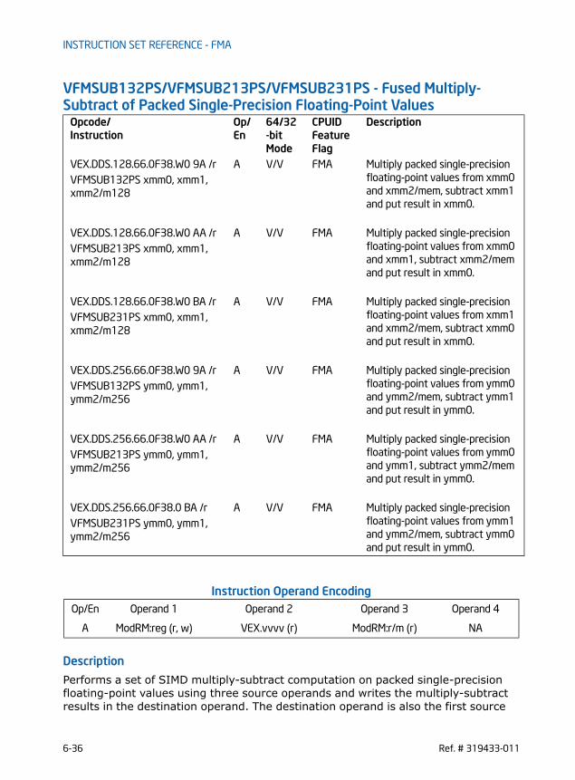
INSTRUCTION SET REFERENCE - FMA
VFMSUB132PS/VFMSUB213PS/VFMSUB231PS - Fused Multiply-Subtract of Packed Single-Precision Floating-Point Values
Instruction Operand Encoding
Description
Performs a set of SIMD multiply-subtract computation on packed single-precision floating-point values using three source operands and writes the multiply-subtract results in the destination operand. The destination operand is also the first source
Opcode/Instruction
Op/ En
64/32-bit Mode
CPUID Feature Flag
Description
VEX.DDS.128.66.0F38.W0 9A /r A V/V FMA Multiply packed single-precision floating-point values from xmm0 and xmm2/mem, subtract xmm1 and put result in xmm0.
VFMSUB132PS xmm0, xmm1, xmm2/m128
VEX.DDS.128.66.0F38.W0 AA /r A V/V FMA Multiply packed single-precision floating-point values from xmm0 and xmm1, subtract xmm2/mem and put result in xmm0.
VFMSUB213PS xmm0, xmm1, xmm2/m128
VEX.DDS.128.66.0F38.W0 BA /r A V/V FMA Multiply packed single-precision floating-point values from xmm1 and xmm2/mem, subtract xmm0 and put result in xmm0.
VFMSUB231PS xmm0, xmm1, xmm2/m128
VEX.DDS.256.66.0F38.W0 9A /r A V/V FMA Multiply packed single-precision floating-point values from ymm0 and ymm2/mem, subtract ymm1 and put result in ymm0.
VFMSUB132PS ymm0, ymm1, ymm2/m256
VEX.DDS.256.66.0F38.W0 AA /r A V/V FMA Multiply packed single-precision floating-point values from ymm0 and ymm1, subtract ymm2/mem and put result in ymm0.
VFMSUB213PS ymm0, ymm1, ymm2/m256
VEX.DDS.256.66.0F38.0 BA /r A V/V FMA Multiply packed single-precision floating-point values from ymm1 and ymm2/mem, subtract ymm0 and put result in ymm0.
VFMSUB231PS ymm0, ymm1, ymm2/m256
Op/En Operand 1 Operand 2 Operand 3 Operand 4
A ModRM:reg (r, w) VEX.vvvv (r) ModRM:r/m (r) NA
6-36 Ref. # 319433-011

INSTRUCTION SET REFERENCE - FMA
operand. The second operand must be a SIMD register. The third source operand can be a SIMD register or a memory location. VFMSUB132PS: Multiplies the four or eight packed single-precision floating-point values from the first source operand to the four or eight packed single-precision floating-point values in the third source operand. From the infinite precision interme-diate result, subtracts the four or eight packed single-precision floating-point values in the second source operand, performs rounding and stores the resulting four or eight packed single-precision floating-point values to the destination operand (first source operand).VFMSUB213PS: Multiplies the four or eight packed single-precision floating-point values from the second source operand to the four or eight packed single-precision floating-point values in the first source operand. From the infinite precision interme-diate result, subtracts the four or eight packed single-precision floating-point values in the third source operand, performs rounding and stores the resulting four or eight packed single-precision floating-point values to the destination operand (first source operand).VFMSUB231PS: Multiplies the four or eight packed single-precision floating-point values from the second source to the four or eight packed single-precision floating-point values in the third source operand. From the infinite precision intermediate result, subtracts the four or eight packed single-precision floating-point values in the first source operand, performs rounding and stores the resulting four or eight packed single-precision floating-point values to the destination operand (first source operand).VEX.256 encoded version: The destination operand (also first source operand) is a YMM register and encoded in reg_field. The second source operand is a YMM register and encoded in VEX.vvvv. The third source operand is a YMM register or a 256-bit memory location and encoded in rm_field. VEX.128 encoded version: The destination operand (also first source operand) is a XMM register and encoded in reg_field. The second source operand is a XMM register and encoded in VEX.vvvv. The third source operand is a XMM register or a 128-bit memory location and encoded in rm_field. The upper 128 bits of the YMM destination register are zeroed.Compiler tools may optionally support a complementary mnemonic for each instruc-tion mnemonic listed in the opcode/instruction column of the summary table. The behavior of the complementary mnemonic in situations involving NANs are governed by the definition of the instruction mnemonic defined in the opcode/instruction column. See also Section 2.3.1, “FMA Instruction Operand Order and Arithmetic Behavior”.
Operation
In the operations below, “+” and “*” symbols represent multiplication and addition with infinite precision inputs and outputs (no rounding).
VFMSUB132PS DEST, SRC2, SRC3
Ref. # 319433-011 6-37

INSTRUCTION SET REFERENCE - FMA
IF (VEX.128) THEN MAXVL =4
ELSEIF (VEX.256)MAXVL = 8
FIFor i = 0 to MAXVL-1 {
n = 32*i;DEST[n+31:n] RoundFPControl_MXCSR(DEST[n+31:n]*SRC3[n+31:n] - SRC2[n+31:n])
}IF (VEX.128) THEN
DEST[VLMAX-1:128] 0FI
VFMSUB213PS DEST, SRC2, SRC3 IF (VEX.128) THEN
MAXVL =4ELSEIF (VEX.256)
MAXVL = 8FIFor i = 0 to MAXVL-1 {
n = 32*i;DEST[n+31:n] RoundFPControl_MXCSR(SRC2[n+31:n]*DEST[n+31:n] - SRC3[n+31:n])
}IF (VEX.128) THEN
DEST[VLMAX-1:128] 0FI
VFMSUB231PS DEST, SRC2, SRC3 IF (VEX.128) THEN
MAXVL =4ELSEIF (VEX.256)
MAXVL = 8FIFor i = 0 to MAXVL-1 {
n = 32*i;DEST[n+31:n] RoundFPControl_MXCSR(SRC2[n+31:n]*SRC3[n+31:n] - DEST[n+31:n])
}IF (VEX.128) THEN
DEST[VLMAX-1:128] 0FI
Intel C/C++ Compiler Intrinsic Equivalent
VFMSUB132PS __m128 _mm_fmsub_ps (__m128 a, __m128 b, __m128 c);
6-38 Ref. # 319433-011

INSTRUCTION SET REFERENCE - FMA
VFMSUB213PS __m128 _mm_fmsub_ps (__m128 a, __m128 b, __m128 c);
VFMSUB231PS __m128 _mm_fmsub_ps (__m128 a, __m128 b, __m128 c);
VFMSUB132PS __m256 _mm256_fmsub_ps (__m256 a, __m256 b, __m256 c);
VFMSUB213PS __m256 _mm256_fmsub_ps (__m256 a, __m256 b, __m256 c);
VFMSUB231PS __m256 _mm256_fmsub_ps (__m256 a, __m256 b, __m256 c);
SIMD Floating-Point Exceptions
Overflow, Underflow, Invalid, Precision, Denormal
Other ExceptionsSee Exceptions Type 2
Ref. # 319433-011 6-39

INSTRUCTION SET REFERENCE - FMA
VFMSUB132SD/VFMSUB213SD/VFMSUB231SD - Fused Multiply-Subtract of Scalar Double-Precision Floating-Point Values
Instruction Operand Encoding
Description
Performs a SIMD multiply-subtract computation on the low packed double-precision floating-point values using three source operands and writes the multiply-add result in the destination operand. The destination operand is also the first source operand. The second operand must be a SIMD register. The third source operand can be a SIMD register or a memory location. VFMSUB132SD: Multiplies the low packed double-precision floating-point value from the first source operand to the low packed double-precision floating-point value in the third source operand. From the infinite precision intermediate result, subtracts the low packed double-precision floating-point values in the second source operand, performs rounding and stores the resulting packed double-precision floating-point value to the destination operand (first source operand).VFMSUB213SD: Multiplies the low packed double-precision floating-point value from the second source operand to the low packed double-precision floating-point value in the first source operand. From the infinite precision intermediate result, subtracts the low packed double-precision floating-point value in the third source operand, performs rounding and stores the resulting packed double-precision floating-point value to the destination operand (first source operand).
Opcode/Instruction
Op/ En
64/32-bit Mode
CPUID Feature Flag
Description
VEX.DDS.LIG.128.66.0F38.W1 9B /r
A V/V FMA Multiply scalar double-precision floating-point value from xmm0 and xmm2/mem, subtract xmm1 and put result in xmm0.
VFMSUB132SD xmm0, xmm1, xmm2/m64
VEX.DDS.LIG.128.66.0F38.W1 AB /r
A V/V FMA Multiply scalar double-precision floating-point value from xmm0 and xmm1, subtract xmm2/mem and put result in xmm0.
VFMSUB213SD xmm0, xmm1, xmm2/m64
VEX.DDS.LIG.128.66.0F38.W1 BB /r
A V/V FMA Multiply scalar double-precision floating-point value from xmm1 and xmm2/mem, subtract xmm0 and put result in xmm0.
VFMSUB231SD xmm0, xmm1, xmm2/m64
Op/En Operand 1 Operand 2 Operand 3 Operand 4
A ModRM:reg (r, w) VEX.vvvv (r) ModRM:r/m (r) NA
6-40 Ref. # 319433-011

INSTRUCTION SET REFERENCE - FMA
VFMSUB231SD: Multiplies the low packed double-precision floating-point value from the second source to the low packed double-precision floating-point value in the third source operand. From the infinite precision intermediate result, subtracts the low packed double-precision floating-point value in the first source operand, performs rounding and stores the resulting packed double-precision floating-point value to the destination operand (first source operand).VEX.128 encoded version: The destination operand (also first source operand) is a XMM register and encoded in reg_field. The second source operand is a XMM register and encoded in VEX.vvvv. The third source operand is a XMM register or a 64-bit memory location and encoded in rm_field. The upper bits ([255:128]) of the YMM destination register are zeroed.Compiler tools may optionally support a complementary mnemonic for each instruc-tion mnemonic listed in the opcode/instruction column of the summary table. The behavior of the complementary mnemonic in situations involving NANs are governed by the definition of the instruction mnemonic defined in the opcode/instruction column. See also Section 2.3.1, “FMA Instruction Operand Order and Arithmetic Behavior”.
Operation
In the operations below, “-” and “*” symbols represent multiplication and addition with infinite precision inputs and outputs (no rounding).
VFMSUB132SD DEST, SRC2, SRC3 DEST[63:0] RoundFPControl_MXCSR(DEST[63:0]*SRC3[63:0] - SRC2[63:0])DEST[127:64] DEST[127:64]DEST[VLMAX-1:128] 0
VFMSUB213SD DEST, SRC2, SRC3 DEST[63:0] RoundFPControl_MXCSR(SRC2[63:0]*DEST[63:0] - SRC3[63:0])DEST[127:64] DEST[127:64]DEST[VLMAX-1:128] 0
VFMSUB231SD DEST, SRC2, SRC3 DEST[63:0] RoundFPControl_MXCSR(SRC2[63:0]*SRC3[63:0] - DEST[63:0])DEST[127:64] DEST[127:64]DEST[VLMAX-1:128] 0
Intel C/C++ Compiler Intrinsic Equivalent
VFMSUB132SD __m128d _mm_fmsub_sd (__m128d a, __m128d b, __m128d c);
VFMSUB213SD __m128d _mm_fmsub_sd (__m128d a, __m128d b, __m128d c);
VFMSUB231SD __m128d _mm_fmsub_sd (__m128d a, __m128d b, __m128d c);
Ref. # 319433-011 6-41

INSTRUCTION SET REFERENCE - FMA
SIMD Floating-Point Exceptions
Overflow, Underflow, Invalid, Precision, Denormal
Other ExceptionsSee Exceptions Type 3
6-42 Ref. # 319433-011

INSTRUCTION SET REFERENCE - FMA
VFMSUB132SS/VFMSUB213SS/VFMSUB231SS - Fused Multiply-Subtract of Scalar Single-Precision Floating-Point Values
Instruction Operand Encoding
Description
Performs a SIMD multiply-subtract computation on the low packed single-precision floating-point values using three source operands and writes the multiply-add result in the destination operand. The destination operand is also the first source operand. The second operand must be a SIMD register. The third source operand can be a SIMD register or a memory location. VFMSUB132SS: Multiplies the low packed single-precision floating-point value from the first source operand to the low packed single-precision floating-point value in the third source operand. From the infinite precision intermediate result, subtracts the low packed single-precision floating-point values in the second source operand, performs rounding and stores the resulting packed single-precision floating-point value to the destination operand (first source operand).VFMSUB213SS: Multiplies the low packed single-precision floating-point value from the second source operand to the low packed single-precision floating-point value in the first source operand. From the infinite precision intermediate result, subtracts the low packed single-precision floating-point value in the third source operand,
Opcode/Instruction
Op/ En
64/32-bit Mode
CPUID Feature Flag
Description
VEX.DDS.LIG.128.66.0F38.W0 9B /r
A V/V FMA Multiply scalar single-precision floating-point value from xmm0 and xmm2/mem, subtract xmm1 and put result in xmm0.
VFMSUB132SS xmm0, xmm1, xmm2/m32
VEX.DDS.LIG.128.66.0F38.W0 AB /r
A V/V FMA Multiply scalar single-precision floating-point value from xmm0 and xmm1, subtract xmm2/mem and put result in xmm0.
VFMSUB213SS xmm0, xmm1, xmm2/m32
VEX.DDS.LIG.128.66.0F38.W0 BB /r
A V/V FMA Multiply scalar single-precision floating-point value from xmm1 and xmm2/mem, subtract xmm0 and put result in xmm0.
VFMSUB231SS xmm0, xmm1, xmm2/m32
Op/En Operand 1 Operand 2 Operand 3 Operand 4
A ModRM:reg (r, w) VEX.vvvv (r) ModRM:r/m (r) NA
Ref. # 319433-011 6-43

INSTRUCTION SET REFERENCE - FMA
performs rounding and stores the resulting packed single-precision floating-point value to the destination operand (first source operand).VFMSUB231SS: Multiplies the low packed single-precision floating-point value from the second source to the low packed single-precision floating-point value in the third source operand. From the infinite precision intermediate result, subtracts the low packed single-precision floating-point value in the first source operand, performs rounding and stores the resulting packed single-precision floating-point value to the destination operand (first source operand).VEX.128 encoded version: The destination operand (also first source operand) is a XMM register and encoded in reg_field. The second source operand is a XMM register and encoded in VEX.vvvv. The third source operand is a XMM register or a 32-bit memory location and encoded in rm_field. The upper bits ([255:128]) of the YMM destination register are zeroed.Compiler tools may optionally support a complementary mnemonic for each instruc-tion mnemonic listed in the opcode/instruction column of the summary table. The behavior of the complementary mnemonic in situations involving NANs are governed by the definition of the instruction mnemonic defined in the opcode/instruction column. See also Section 2.3.1, “FMA Instruction Operand Order and Arithmetic Behavior”.
Operation
In the operations below, “-” and “*” symbols represent multiplication and addition with infinite precision inputs and outputs (no rounding).
VFMSUB132SS DEST, SRC2, SRC3 DEST[31:0] RoundFPControl_MXCSR(DEST[31:0]*SRC3[31:0] - SRC2[31:0])DEST[127:32] DEST[127:32]DEST[VLMAX-1:128] 0
VFMSUB213SS DEST, SRC2, SRC3 DEST[31:0] RoundFPControl_MXCSR(SRC2[31:0]*DEST[31:0] - SRC3[31:0])DEST[127:32] DEST[127:32]DEST[VLMAX-1:128] 0
VFMSUB231SS DEST, SRC2, SRC3 DEST[31:0] RoundFPControl_MXCSR(SRC2[31:0]*SRC3[63:0] - DEST[31:0])DEST[127:32] DEST[127:32]DEST[VLMAX-1:128] 0
Intel C/C++ Compiler Intrinsic Equivalent
VFMSUB132SS __m128 _mm_fmsub_ss (__m128 a, __m128 b, __m128 c);
VFMSUB213SS __m128 _mm_fmsub_ss (__m128 a, __m128 b, __m128 c);
6-44 Ref. # 319433-011

INSTRUCTION SET REFERENCE - FMA
VFMSUB231SS __m128 _mm_fmsub_ss (__m128 a, __m128 b, __m128 c);
SIMD Floating-Point Exceptions
Overflow, Underflow, Invalid, Precision, Denormal
Other ExceptionsSee Exceptions Type 3
Ref. # 319433-011 6-45

INSTRUCTION SET REFERENCE - FMA
VFNMADD132PD/VFNMADD213PD/VFNMADD231PD - Fused Negative Multiply-Add of Packed Double-Precision Floating-Point Values
Opcode/Instruction
Op/ En
64/32-bit Mode
CPUID Feature Flag
Description
VEX.DDS.128.66.0F38.W1 9C /r A V/V FMA Multiply packed double-preci-sion floating-point values from xmm0 and xmm2/mem, negate the multiplication result and add to xmm1 and put result in xmm0.
VFNMADD132PD xmm0, xmm1, xmm2/m128
VEX.DDS.128.66.0F38.W1 AC /r A V/V FMA Multiply packed double-preci-sion floating-point values from xmm0 and xmm1, negate the multiplication result and add to xmm2/mem and put result in xmm0.
VFNMADD213PD xmm0, xmm1, xmm2/m128
VEX.DDS.128.66.0F38.W1 BC /r A V/V FMA Multiply packed double-preci-sion floating-point values from xmm1 and xmm2/mem, negate the multiplication result and add to xmm0 and put result in xmm0.
VFNMADD231PD xmm0, xmm1, xmm2/m128
VEX.DDS.256.66.0F38.W1 9C /r A V/V FMA Multiply packed double-preci-sion floating-point values from ymm0 and ymm2/mem, negate the multiplication result and add to ymm1 and put result in ymm0.
VFNMADD132PD ymm0, ymm1, ymm2/m256
VEX.DDS.256.66.0F38.W1 AC /r A V/V FMA Multiply packed double-preci-sion floating-point values from ymm0 and ymm1, negate the multiplication result and add to ymm2/mem and put result in ymm0.
VFNMADD213PD ymm0, ymm1, ymm2/m256
VEX.DDS.256.66.0F38.W1 BC /r A V/V FMA Multiply packed double-preci-sion floating-point values from ymm1 and ymm2/mem, negate the multiplication result and add to ymm0 and put result in ymm0.
VFNMADD231PD ymm0, ymm1, ymm2/m256
6-46 Ref. # 319433-011

INSTRUCTION SET REFERENCE - FMA
Instruction Operand Encoding
Description
VFNMADD132PD: Multiplies the two or four packed double-precision floating-point values from the first source operand to the two or four packed double-precision floating-point values in the third source operand, adds the negated infinite precision intermediate result to the two or four packed double-precision floating-point values in the second source operand, performs rounding and stores the resulting two or four packed double-precision floating-point values to the destination operand (first source operand).VFNMADD213PD: Multiplies the two or four packed double-precision floating-point values from the second source operand to the two or four packed double-precision floating-point values in the first source operand, adds the negated infinite precision intermediate result to the two or four packed double-precision floating-point values in the third source operand, performs rounding and stores the resulting two or four packed double-precision floating-point values to the destination operand (first source operand).VFNMADD231PD: Multiplies the two or four packed double-precision floating-point values from the second source to the two or four packed double-precision floating-point values in the third source operand, adds the negated infinite precision interme-diate result to the two or four packed double-precision floating-point values in the first source operand, performs rounding and stores the resulting two or four packed double-precision floating-point values to the destination operand (first source operand).VEX.256 encoded version: The destination operand (also first source operand) is a YMM register and encoded in reg_field. The second source operand is a YMM register and encoded in VEX.vvvv. The third source operand is a YMM register or a 256-bit memory location and encoded in rm_field. VEX.128 encoded version: The destination operand (also first source operand) is a XMM register and encoded in reg_field. The second source operand is a XMM register and encoded in VEX.vvvv. The third source operand is a XMM register or a 128-bit memory location and encoded in rm_field. The upper 128 bits of the YMM destination register are zeroed.Compiler tools may optionally support a complementary mnemonic for each instruc-tion mnemonic listed in the opcode/instruction column of the summary table. The behavior of the complementary mnemonic in situations involving NANs are governed by the definition of the instruction mnemonic defined in the opcode/instruction column. See also Section 2.3.1, “FMA Instruction Operand Order and Arithmetic Behavior”.
Op/En Operand 1 Operand 2 Operand 3 Operand 4
A ModRM:reg (r, w) VEX.vvvv (r) ModRM:r/m (r) NA
Ref. # 319433-011 6-47

INSTRUCTION SET REFERENCE - FMA
Operation
In the operations below, “-” and “*” symbols represent multiplication and addition with infinite precision inputs and outputs (no rounding).
VFNMADD132PD DEST, SRC2, SRC3 IF (VEX.128) THEN
MAXVL =2ELSEIF (VEX.256)
MAXVL = 4FIFor i = 0 to MAXVL-1 {
n = 64*i;DEST[n+63:n] RoundFPControl_MXCSR(-(DEST[n+63:n]*SRC3[n+63:n]) + SRC2[n+63:n])
}IF (VEX.128) THENDEST[VLMAX-1:128] 0FI
VFNMADD213PD DEST, SRC2, SRC3 IF (VEX.128) THEN
MAXVL =2ELSEIF (VEX.256)
MAXVL = 4FIFor i = 0 to MAXVL-1 {
n = 64*i;DEST[n+63:n] RoundFPControl_MXCSR(-(SRC2[n+63:n]*DEST[n+63:n]) + SRC3[n+63:n])
}IF (VEX.128) THENDEST[VLMAX-1:128] 0FI
VFNMADD231PD DEST, SRC2, SRC3 IF (VEX.128) THEN
MAXVL =2ELSEIF (VEX.256)
MAXVL = 4FIFor i = 0 to MAXVL-1 {
n = 64*i;DEST[n+63:n] RoundFPControl_MXCSR(-(SRC2[n+63:n]*SRC3[n+63:n]) + DEST[n+63:n])
}IF (VEX.128) THEN
6-48 Ref. # 319433-011

INSTRUCTION SET REFERENCE - FMA
DEST[VLMAX-1:128] 0FI
Intel C/C++ Compiler Intrinsic Equivalent
VFNMADD132PD __m128d _mm_fnmadd_pd (__m128d a, __m128d b, __m128d c);
VFNMADD213PD __m128d _mm_fnmadd_pd (__m128d a, __m128d b, __m128d c);
VFNMADD231PD __m128d _mm_fnmadd_pd (__m128d a, __m128d b, __m128d c);
VFNMADD132PD __m256d _mm256_fnmadd_pd (__m256d a, __m256d b, __m256d c);
VFNMADD213PD __m256d _mm256_fnmadd_pd (__m256d a, __m256d b, __m256d c);
VFNMADD231PD __m256d _mm256_fnmadd_pd (__m256d a, __m256d b, __m256d c);
SIMD Floating-Point Exceptions
Overflow, Underflow, Invalid, Precision, Denormal
Other ExceptionsSee Exceptions Type 2
Ref. # 319433-011 6-49

INSTRUCTION SET REFERENCE - FMA
VFNMADD132PS/VFNMADD213PS/VFNMADD231PS - Fused Negative Multiply-Add of Packed Single-Precision Floating-Point Values
Opcode/Instruction
Op/ En
64/32-bit Mode
CPUID Feature Flag
Description
VEX.DDS.128.66.0F38.W0 9C /r A V/V FMA Multiply packed single-precision floating-point values from xmm0 and xmm2/mem, negate the mul-tiplication result and add to xmm1 and put result in xmm0.
VFNMADD132PS xmm0, xmm1, xmm2/m128
VEX.DDS.128.66.0F38.W0 AC /r A V/V FMA Multiply packed single-precision floating-point values from xmm0 and xmm1, negate the multipli-cation result and add to xmm2/mem and put result in xmm0.
VFNMADD213PS xmm0, xmm1, xmm2/m128
VEX.DDS.128.66.0F38.W0 BC /r A V/V FMA Multiply packed single-precision floating-point values from xmm1 and xmm2/mem, negate the mul-tiplication result and add to xmm0 and put result in xmm0.
VFNMADD231PS xmm0, xmm1, xmm2/m128
VEX.DDS.256.66.0F38.W0 9C /r A V/V FMA Multiply packed single-precision floating-point values from ymm0 and ymm2/mem, negate the mul-tiplication result and add to ymm1 and put result in ymm0.
VFNMADD132PS ymm0, ymm1, ymm2/m256
VEX.DDS.256.66.0F38.W0 AC /r A V/V FMA Multiply packed single-precision floating-point values from ymm0 and ymm1, negate the multipli-cation result and add to ymm2/mem and put result in ymm0.
VFNMADD213PS ymm0, ymm1, ymm2/m256
VEX.DDS.256.66.0F38.0 BC /r A V/V FMA Multiply packed single-precision floating-point values from ymm1 and ymm2/mem, negate the mul-tiplication result and add to ymm0 and put result in ymm0.
VFNMADD231PS ymm0, ymm1, ymm2/m256
6-50 Ref. # 319433-011

INSTRUCTION SET REFERENCE - FMA
Instruction Operand Encoding
Description
VFNMADD132PS: Multiplies the four or eight packed single-precision floating-point values from the first source operand to the four or eight packed single-precision floating-point values in the third source operand, adds the negated infinite precision intermediate result to the four or eight packed single-precision floating-point values in the second source operand, performs rounding and stores the resulting four or eight packed single-precision floating-point values to the destination operand (first source operand).VFNMADD213PS: Multiplies the four or eight packed single-precision floating-point values from the second source operand to the four or eight packed single-precision floating-point values in the first source operand, adds the negated infinite precision intermediate result to the four or eight packed single-precision floating-point values in the third source operand, performs rounding and stores the resulting the four or eight packed single-precision floating-point values to the destination operand (first source operand).VFNMADD231PS: Multiplies the four or eight packed single-precision floating-point values from the second source operand to the four or eight packed single-precision floating-point values in the third source operand, adds the negated infinite precision intermediate result to the four or eight packed single-precision floating-point values in the first source operand, performs rounding and stores the resulting four or eight packed single-precision floating-point values to the destination operand (first source operand).VEX.256 encoded version: The destination operand (also first source operand) is a YMM register and encoded in reg_field. The second source operand is a YMM register and encoded in VEX.vvvv. The third source operand is a YMM register or a 256-bit memory location and encoded in rm_field. VEX.128 encoded version: The destination operand (also first source operand) is a XMM register and encoded in reg_field. The second source operand is a XMM register and encoded in VEX.vvvv. The third source operand is a XMM register or a 128-bit memory location and encoded in rm_field. The upper 128 bits of the YMM destination register are zeroed.Compiler tools may optionally support a complementary mnemonic for each instruc-tion mnemonic listed in the opcode/instruction column of the summary table. The behavior of the complementary mnemonic in situations involving NANs are governed by the definition of the instruction mnemonic defined in the opcode/instruction column. See also Section 2.3.1, “FMA Instruction Operand Order and Arithmetic Behavior”.
Op/En Operand 1 Operand 2 Operand 3 Operand 4
A ModRM:reg (r, w) VEX.vvvv (r) ModRM:r/m (r) NA
Ref. # 319433-011 6-51

INSTRUCTION SET REFERENCE - FMA
Operation
In the operations below, “+” and “*” symbols represent multiplication and addition with infinite precision inputs and outputs (no rounding).
VFNMADD132PS DEST, SRC2, SRC3 IF (VEX.128) THEN
MAXVL =4ELSEIF (VEX.256)
MAXVL = 8FIFor i = 0 to MAXVL-1 {
n = 32*i;DEST[n+31:n] RoundFPControl_MXCSR(- (DEST[n+31:n]*SRC3[n+31:n]) + SRC2[n+31:n])
}IF (VEX.128) THEN
DEST[VLMAX-1:128] 0FI
VFNMADD213PS DEST, SRC2, SRC3 IF (VEX.128) THEN
MAXVL =4ELSEIF (VEX.256)
MAXVL = 8FIFor i = 0 to MAXVL-1 {
n = 32*i;DEST[n+31:n] RoundFPControl_MXCSR(- (SRC2[n+31:n]*DEST[n+31:n]) + SRC3[n+31:n])
}IF (VEX.128) THEN
DEST[VLMAX-1:128] 0FI
VFNMADD231PS DEST, SRC2, SRC3 IF (VEX.128) THEN
MAXVL =4ELSEIF (VEX.256)
MAXVL = 8FIFor i = 0 to MAXVL-1 {
n = 32*i;DEST[n+31:n] RoundFPControl_MXCSR(- (SRC2[n+31:n]*SRC3[n+31:n]) + DEST[n+31:n])
}IF (VEX.128) THEN
6-52 Ref. # 319433-011

INSTRUCTION SET REFERENCE - FMA
DEST[VLMAX-1:128] 0FI
Intel C/C++ Compiler Intrinsic Equivalent
VFNMADD132PS __m128 _mm_fnmadd_ps (__m128 a, __m128 b, __m128 c);
VFNMADD213PS __m128 _mm_fnmadd_ps (__m128 a, __m128 b, __m128 c);
VFNMADD231PS __m128 _mm_fnmadd_ps (__m128 a, __m128 b, __m128 c);
VFNMADD132PS __m256 _mm256_fnmadd_ps (__m256 a, __m256 b, __m256 c);
VFNMADD213PS __m256 _mm256_fnmadd_ps (__m256 a, __m256 b, __m256 c);
VFNMADD231PS __m256 _mm256_fnmadd_ps (__m256 a, __m256 b, __m256 c);
SIMD Floating-Point Exceptions
Overflow, Underflow, Invalid, Precision, Denormal
Other ExceptionsSee Exceptions Type 2
Ref. # 319433-011 6-53
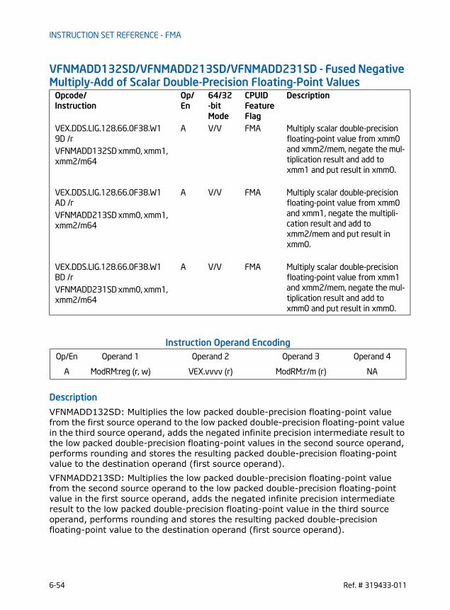
INSTRUCTION SET REFERENCE - FMA
VFNMADD132SD/VFNMADD213SD/VFNMADD231SD - Fused Negative Multiply-Add of Scalar Double-Precision Floating-Point Values
Instruction Operand Encoding
Description
VFNMADD132SD: Multiplies the low packed double-precision floating-point value from the first source operand to the low packed double-precision floating-point value in the third source operand, adds the negated infinite precision intermediate result to the low packed double-precision floating-point values in the second source operand, performs rounding and stores the resulting packed double-precision floating-point value to the destination operand (first source operand).VFNMADD213SD: Multiplies the low packed double-precision floating-point value from the second source operand to the low packed double-precision floating-point value in the first source operand, adds the negated infinite precision intermediate result to the low packed double-precision floating-point value in the third source operand, performs rounding and stores the resulting packed double-precision floating-point value to the destination operand (first source operand).
Opcode/Instruction
Op/ En
64/32-bit Mode
CPUID Feature Flag
Description
VEX.DDS.LIG.128.66.0F38.W1 9D /r
A V/V FMA Multiply scalar double-precision floating-point value from xmm0 and xmm2/mem, negate the mul-tiplication result and add to xmm1 and put result in xmm0.
VFNMADD132SD xmm0, xmm1, xmm2/m64
VEX.DDS.LIG.128.66.0F38.W1 AD /r
A V/V FMA Multiply scalar double-precision floating-point value from xmm0 and xmm1, negate the multipli-cation result and add to xmm2/mem and put result in xmm0.
VFNMADD213SD xmm0, xmm1, xmm2/m64
VEX.DDS.LIG.128.66.0F38.W1 BD /r
A V/V FMA Multiply scalar double-precision floating-point value from xmm1 and xmm2/mem, negate the mul-tiplication result and add to xmm0 and put result in xmm0.
VFNMADD231SD xmm0, xmm1, xmm2/m64
Op/En Operand 1 Operand 2 Operand 3 Operand 4
A ModRM:reg (r, w) VEX.vvvv (r) ModRM:r/m (r) NA
6-54 Ref. # 319433-011

INSTRUCTION SET REFERENCE - FMA
VFNMADD231SD: Multiplies the low packed double-precision floating-point value from the second source to the low packed double-precision floating-point value in the third source operand, adds the negated infinite precision intermediate result to the low packed double-precision floating-point value in the first source operand, performs rounding and stores the resulting packed double-precision floating-point value to the destination operand (first source operand).VEX.128 encoded version: The destination operand (also first source operand) is a XMM register and encoded in reg_field. The second source operand is a XMM register and encoded in VEX.vvvv. The third source operand is a XMM register or a 64-bit memory location and encoded in rm_field. The upper bits ([255:128]) of the YMM destination register are zeroed.Compiler tools may optionally support a complementary mnemonic for each instruc-tion mnemonic listed in the opcode/instruction column of the summary table. The behavior of the complementary mnemonic in situations involving NANs are governed by the definition of the instruction mnemonic defined in the opcode/instruction column. See also Section 2.3.1, “FMA Instruction Operand Order and Arithmetic Behavior”.
Operation
In the operations below, “+” and “*” symbols represent multiplication and addition with infinite precision inputs and outputs (no rounding).
VFNMADD132SD DEST, SRC2, SRC3 DEST[63:0] RoundFPControl_MXCSR(- (DEST[63:0]*SRC3[63:0]) + SRC2[63:0])DEST[127:64] DEST[127:64]DEST[VLMAX-1:128] 0
VFNMADD213SD DEST, SRC2, SRC3 DEST[63:0] RoundFPControl_MXCSR(- (SRC2[63:0]*DEST[63:0]) + SRC3[63:0])DEST[127:64] DEST[127:64]DEST[VLMAX-1:128] 0
VFNMADD231SD DEST, SRC2, SRC3 DEST[63:0] RoundFPControl_MXCSR(- (SRC2[63:0]*SRC3[63:0]) + DEST[63:0])DEST[127:64] DEST[127:64]DEST[VLMAX-1:128] 0
Intel C/C++ Compiler Intrinsic Equivalent
VFNMADD132SD __m128d _mm_fnmadd_sd (__m128d a, __m128d b, __m128d c);
VFNMADD213SD __m128d _mm_fnmadd_sd (__m128d a, __m128d b, __m128d c);
VFNMADD231SD __m128d _mm_fnmadd_sd (__m128d a, __m128d b, __m128d c);
Ref. # 319433-011 6-55

INSTRUCTION SET REFERENCE - FMA
SIMD Floating-Point Exceptions
Overflow, Underflow, Invalid, Precision, Denormal
Other ExceptionsSee Exceptions Type 3
6-56 Ref. # 319433-011

INSTRUCTION SET REFERENCE - FMA
VFNMADD132SS/VFNMADD213SS/VFNMADD231SS - Fused Negative Multiply-Add of Scalar Single-Precision Floating-Point Values
Instruction Operand Encoding
Description
VFNMADD132SS: Multiplies the low packed single-precision floating-point value from the first source operand to the low packed single-precision floating-point value in the third source operand, adds the negated infinite precision intermediate result to the low packed single-precision floating-point value in the second source operand, performs rounding and stores the resulting packed single-precision floating-point value to the destination operand (first source operand).VFNMADD213SS: Multiplies the low packed single-precision floating-point value from the second source operand to the low packed single-precision floating-point value in the first source operand, adds the negated infinite precision intermediate result to the low packed single-precision floating-point value in the third source operand, performs rounding and stores the resulting packed single-precision floating-point value to the destination operand (first source operand).
Opcode/Instruction
Op/ En
64/32-bit Mode
CPUID Feature Flag
Description
VEX.DDS.LIG.128.66.0F38.W0 9D /r
A V/V FMA Multiply scalar single-precision floating-point value from xmm0 and xmm2/mem, negate the mul-tiplication result and add to xmm1 and put result in xmm0.
VFNMADD132SS xmm0, xmm1, xmm2/m32
VEX.DDS.LIG.128.66.0F38.W0 AD /r
A V/V FMA Multiply scalar single-precision floating-point value from xmm0 and xmm1, negate the multipli-cation result and add to xmm2/mem and put result in xmm0.
VFNMADD213SS xmm0, xmm1, xmm2/m32
VEX.DDS.LIG.128.66.0F38.W0 BD /r
A V/V FMA Multiply scalar single-precision floating-point value from xmm1 and xmm2/mem, negate the mul-tiplication result and add to xmm0 and put result in xmm0.
VFNMADD231SS xmm0, xmm1, xmm2/m32
Op/En Operand 1 Operand 2 Operand 3 Operand 4
A ModRM:reg (r, w) VEX.vvvv (r) ModRM:r/m (r) NA
Ref. # 319433-011 6-57

INSTRUCTION SET REFERENCE - FMA
VFNMADD231SS: Multiplies the low packed single-precision floating-point value from the second source operand to the low packed single-precision floating-point value in the third source operand, adds the negated infinite precision intermediate result to the low packed single-precision floating-point value in the first source operand, performs rounding and stores the resulting packed single-precision floating-point value to the destination operand (first source operand).VEX.128 encoded version: The destination operand (also first source operand) is a XMM register and encoded in reg_field. The second source operand is a XMM register and encoded in VEX.vvvv. The third source operand is a XMM register or a 32-bit memory location and encoded in rm_field. The upper bits ([255:128]) of the YMM destination register are zeroed.Compiler tools may optionally support a complementary mnemonic for each instruc-tion mnemonic listed in the opcode/instruction column of the summary table. The behavior of the complementary mnemonic in situations involving NANs are governed by the definition of the instruction mnemonic defined in the opcode/instruction column. See also Section 2.3.1, “FMA Instruction Operand Order and Arithmetic Behavior”.
Operation
In the operations below, “+” and “*” symbols represent multiplication and addition with infinite precision inputs and outputs (no rounding).
VFNMADD132SS DEST, SRC2, SRC3 DEST[31:0] RoundFPControl_MXCSR(- (DEST[31:0]*SRC3[31:0]) + SRC2[31:0])DEST[127:32] DEST[127:32]DEST[VLMAX-1:128] 0
VFNMADD213SS DEST, SRC2, SRC3 DEST[31:0] RoundFPControl_MXCSR(- (SRC2[31:0]*DEST[31:0]) + SRC3[31:0])DEST[127:32] DEST[127:32]DEST[VLMAX-1:128] 0
VFNMADD231SS DEST, SRC2, SRC3 DEST[31:0] RoundFPControl_MXCSR(- (SRC2[31:0]*SRC3[63:0]) + DEST[31:0])DEST[127:32] DEST[127:32]DEST[VLMAX-1:128] 0
Intel C/C++ Compiler Intrinsic Equivalent
VFNMADD132SS __m128 _mm_fnmadd_ss (__m128 a, __m128 b, __m128 c);
VFNMADD213SS __m128 _mm_fnmadd_ss (__m128 a, __m128 b, __m128 c);
VFNMADD231SS __m128 _mm_fnmadd_ss (__m128 a, __m128 b, __m128 c);
6-58 Ref. # 319433-011

INSTRUCTION SET REFERENCE - FMA
SIMD Floating-Point Exceptions
Overflow, Underflow, Invalid, Precision, Denormal
Other ExceptionsSee Exceptions Type 3
Ref. # 319433-011 6-59

INSTRUCTION SET REFERENCE - FMA
VFNMSUB132PD/VFNMSUB213PD/VFNMSUB231PD - Fused Negative Multiply-Subtract of Packed Double-Precision Floating-Point Values
Opcode/Instruction
Op/ En
64/32-bit Mode
CPUID Feature Flag
Description
VEX.DDS.128.66.0F38.W1 9E /r A V/V FMA Multiply packed double-precision floating-point values from xmm0 and xmm2/mem, negate the multiplication result and subtract xmm1 and put result in xmm0.
VFNMSUB132PD xmm0, xmm1, xmm2/m128
VEX.DDS.128.66.0F38.W1 AE /r A V/V FMA Multiply packed double-precision floating-point values from xmm0 and xmm1, negate the multiplication result and sub-tract xmm2/mem and put result in xmm0.
VFNMSUB213PD xmm0, xmm1, xmm2/m128
VEX.DDS.128.66.0F38.W1 BE /r A V/V FMA Multiply packed double-precision floating-point values from xmm1 and xmm2/mem, negate the multiplication result and subtract xmm0 and put result in xmm0.
VFNMSUB231PD xmm0, xmm1, xmm2/m128
VEX.DDS.256.66.0F38.W1 9E /r A V/V FMA Multiply packed double-precision floating-point values from ymm0 and ymm2/mem, negate the multiplication result and subtract ymm1 and put result in ymm0.
VFNMSUB132PD ymm0, ymm1, ymm2/m256
VEX.DDS.256.66.0F38.W1 AE /r A V/V FMA Multiply packed double-precision floating-point values from ymm0 and ymm1, negate the multiplication result and sub-tract ymm2/mem and put result in ymm0.
VFNMSUB213PD ymm0, ymm1, ymm2/m256
VEX.DDS.256.66.0F38.W1 BE /r A V/V FMA Multiply packed double-precision floating-point values from ymm1 and ymm2/mem, negate the multiplication result and subtract ymm0 and put result in ymm0.
VFNMSUB231PD ymm0, ymm1, ymm2/m256
6-60 Ref. # 319433-011

INSTRUCTION SET REFERENCE - FMA
Instruction Operand Encoding
Description
VFNMSUB132PD: Multiplies the two or four packed double-precision floating-point values from the first source operand to the two or four packed double-precision floating-point values in the third source operand. From negated infinite precision intermediate results, subtracts the two or four packed double-precision floating-point values in the second source operand, performs rounding and stores the resulting two or four packed double-precision floating-point values to the destination operand (first source operand).VFMSUB213PD: Multiplies the two or four packed double-precision floating-point values from the second source operand to the two or four packed double-precision floating-point values in the first source operand. From negated infinite precision intermediate results, subtracts the two or four packed double-precision floating-point values in the third source operand, performs rounding and stores the resulting two or four packed double-precision floating-point values to the destination operand (first source operand).VFMSUB231PD: Multiplies the two or four packed double-precision floating-point values from the second source to the two or four packed double-precision floating-point values in the third source operand. From negated infinite precision interme-diate results, subtracts the two or four packed double-precision floating-point values in the first source operand, performs rounding and stores the resulting two or four packed double-precision floating-point values to the destination operand (first source operand).VEX.256 encoded version: The destination operand (also first source operand) is a YMM register and encoded in reg_field. The second source operand is a YMM register and encoded in VEX.vvvv. The third source operand is a YMM register or a 256-bit memory location and encoded in rm_field. VEX.128 encoded version: The destination operand (also first source operand) is a XMM register and encoded in reg_field. The second source operand is a XMM register and encoded in VEX.vvvv. The third source operand is a XMM register or a 128-bit memory location and encoded in rm_field. The upper 128 bits of the YMM destination register are zeroed.Compiler tools may optionally support a complementary mnemonic for each instruc-tion mnemonic listed in the opcode/instruction column of the summary table. The behavior of the complementary mnemonic in situations involving NANs are governed by the definition of the instruction mnemonic defined in the opcode/instruction column. See also Section 2.3.1, “FMA Instruction Operand Order and Arithmetic Behavior”.
Op/En Operand 1 Operand 2 Operand 3 Operand 4
A ModRM:reg (r, w) VEX.vvvv (r) ModRM:r/m (r) NA
Ref. # 319433-011 6-61

INSTRUCTION SET REFERENCE - FMA
Operation
In the operations below, “-” and “*” symbols represent multiplication and addition with infinite precision inputs and outputs (no rounding).
VFNMSUB132PD DEST, SRC2, SRC3 IF (VEX.128) THEN
MAXVL =2ELSEIF (VEX.256)
MAXVL = 4FIFor i = 0 to MAXVL-1 {
n = 64*i;DEST[n+63:n] RoundFPControl_MXCSR( - (DEST[n+63:n]*SRC3[n+63:n]) - SRC2[n+63:n])
}IF (VEX.128) THENDEST[VLMAX-1:128] 0FI
VFNMSUB213PD DEST, SRC2, SRC3 IF (VEX.128) THEN
MAXVL =2ELSEIF (VEX.256)
MAXVL = 4FIFor i = 0 to MAXVL-1 {
n = 64*i;DEST[n+63:n] RoundFPControl_MXCSR( - (SRC2[n+63:n]*DEST[n+63:n]) - SRC3[n+63:n])
}IF (VEX.128) THENDEST[VLMAX-1:128] 0FI
VFNMSUB231PD DEST, SRC2, SRC3 IF (VEX.128) THEN
MAXVL =2ELSEIF (VEX.256)
MAXVL = 4FIFor i = 0 to MAXVL-1 {
n = 64*i;DEST[n+63:n] RoundFPControl_MXCSR( - (SRC2[n+63:n]*SRC3[n+63:n]) - DEST[n+63:n])
}IF (VEX.128) THEN
6-62 Ref. # 319433-011

INSTRUCTION SET REFERENCE - FMA
DEST[VLMAX-1:128] 0FI
Intel C/C++ Compiler Intrinsic Equivalent
VFNMSUB132PD __m128d _mm_fnmsub_pd (__m128d a, __m128d b, __m128d c);
VFNMSUB213PD __m128d _mm_fnmsub_pd (__m128d a, __m128d b, __m128d c);
VFNMSUB231PD __m128d _mm_fnmsub_pd (__m128d a, __m128d b, __m128d c);
VFNMSUB132PD __m256d _mm256_fnmsub_pd (__m256d a, __m256d b, __m256d c);
VFNMSUB213PD __m256d _mm256_fnmsub_pd (__m256d a, __m256d b, __m256d c);
VFNMSUB231PD __m256d _mm256_fnmsub_pd (__m256d a, __m256d b, __m256d c);
SIMD Floating-Point Exceptions
Overflow, Underflow, Invalid, Precision, Denormal
Other ExceptionsSee Exceptions Type 2
Ref. # 319433-011 6-63

INSTRUCTION SET REFERENCE - FMA
VFNMSUB132PS/VFNMSUB213PS/VFNMSUB231PS - Fused Negative Multiply-Subtract of Packed Single-Precision Floating-Point Values
Opcode/Instruction
Op/ En
64/32-bit Mode
CPUID Feature Flag
Description
VEX.DDS.128.66.0F38.W0 9E /r A V/V FMA Multiply packed single-precision floating-point values from xmm0 and xmm2/mem, negate the mul-tiplication result and subtract xmm1 and put result in xmm0.
VFNMSUB132PS xmm0, xmm1, xmm2/m128
VEX.DDS.128.66.0F38.W0 AE /r A V/V FMA Multiply packed single-precision floating-point values from xmm0 and xmm1, negate the multipli-cation result and subtract xmm2/mem and put result in xmm0.
VFNMSUB213PS xmm0, xmm1, xmm2/m128
VEX.DDS.128.66.0F38.W0 BE /r A V/V FMA Multiply packed single-precision floating-point values from xmm1 and xmm2/mem, negate the mul-tiplication result and subtract xmm0 and put result in xmm0.
VFNMSUB231PS xmm0, xmm1, xmm2/m128
VEX.DDS.256.66.0F38.W0 9E /r A V/V FMA Multiply packed single-precision floating-point values from ymm0 and ymm2/mem, negate the mul-tiplication result and subtract ymm1 and put result in ymm0.
VFNMSUB132PS ymm0, ymm1, ymm2/m256
VEX.DDS.256.66.0F38.W0 AE /r A V/V FMA Multiply packed single-precision floating-point values from ymm0 and ymm1, negate the multipli-cation result and subtract ymm2/mem and put result in ymm0.
VFNMSUB213PS ymm0, ymm1, ymm2/m256
VEX.DDS.256.66.0F38.0 BE /r A V/V FMA Multiply packed single-precision floating-point values from ymm1 and ymm2/mem, negate the mul-tiplication result and subtract ymm0 and put result in ymm0.
VFNMSUB231PS ymm0, ymm1, ymm2/m256
6-64 Ref. # 319433-011
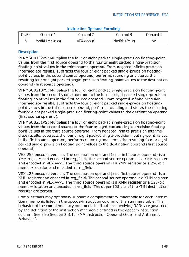
INSTRUCTION SET REFERENCE - FMA
Instruction Operand Encoding
Description
VFNMSUB132PS: Multiplies the four or eight packed single-precision floating-point values from the first source operand to the four or eight packed single-precision floating-point values in the third source operand. From negated infinite precision intermediate results, subtracts the four or eight packed single-precision floating-point values in the second source operand, performs rounding and stores the resulting four or eight packed single-precision floating-point values to the destination operand (first source operand).VFNMSUB213PS: Multiplies the four or eight packed single-precision floating-point values from the second source operand to the four or eight packed single-precision floating-point values in the first source operand. From negated infinite precision intermediate results, subtracts the four or eight packed single-precision floating-point values in the third source operand, performs rounding and stores the resulting four or eight packed single-precision floating-point values to the destination operand (first source operand).VFNMSUB231PS: Multiplies the four or eight packed single-precision floating-point values from the second source to the four or eight packed single-precision floating-point values in the third source operand. From negated infinite precision interme-diate results, subtracts the four or eight packed single-precision floating-point values in the first source operand, performs rounding and stores the resulting four or eight packed single-precision floating-point values to the destination operand (first source operand).VEX.256 encoded version: The destination operand (also first source operand) is a YMM register and encoded in reg_field. The second source operand is a YMM register and encoded in VEX.vvvv. The third source operand is a YMM register or a 256-bit memory location and encoded in rm_field. VEX.128 encoded version: The destination operand (also first source operand) is a XMM register and encoded in reg_field. The second source operand is a XMM register and encoded in VEX.vvvv. The third source operand is a XMM register or a 128-bit memory location and encoded in rm_field. The upper 128 bits of the YMM destination register are zeroed.Compiler tools may optionally support a complementary mnemonic for each instruc-tion mnemonic listed in the opcode/instruction column of the summary table. The behavior of the complementary mnemonic in situations involving NANs are governed by the definition of the instruction mnemonic defined in the opcode/instruction column. See also Section 2.3.1, “FMA Instruction Operand Order and Arithmetic Behavior”.
Op/En Operand 1 Operand 2 Operand 3 Operand 4
A ModRM:reg (r, w) VEX.vvvv (r) ModRM:r/m (r) NA
Ref. # 319433-011 6-65

INSTRUCTION SET REFERENCE - FMA
Operation
In the operations below, “+” and “*” symbols represent multiplication and addition with infinite precision inputs and outputs (no rounding).
VFNMSUB132PS DEST, SRC2, SRC3 IF (VEX.128) THEN
MAXVL =4ELSEIF (VEX.256)
MAXVL = 8FIFor i = 0 to MAXVL-1 {
n = 32*i;DEST[n+31:n] RoundFPControl_MXCSR( - (DEST[n+31:n]*SRC3[n+31:n]) - SRC2[n+31:n])
}IF (VEX.128) THEN
DEST[VLMAX-1:128] 0FI
VFNMSUB213PS DEST, SRC2, SRC3 IF (VEX.128) THEN
MAXVL =4ELSEIF (VEX.256)
MAXVL = 8FIFor i = 0 to MAXVL-1 {
n = 32*i;DEST[n+31:n] RoundFPControl_MXCSR( - (SRC2[n+31:n]*DEST[n+31:n]) - SRC3[n+31:n])
}IF (VEX.128) THEN
DEST[VLMAX-1:128] 0FI
VFNMSUB231PS DEST, SRC2, SRC3 IF (VEX.128) THEN
MAXVL =4ELSEIF (VEX.256)
MAXVL = 8FIFor i = 0 to MAXVL-1 {
n = 32*i;DEST[n+31:n] RoundFPControl_MXCSR( - (SRC2[n+31:n]*SRC3[n+31:n]) - DEST[n+31:n])
}IF (VEX.128) THEN
6-66 Ref. # 319433-011

INSTRUCTION SET REFERENCE - FMA
DEST[VLMAX-1:128] 0FI
Intel C/C++ Compiler Intrinsic Equivalent
VFNMSUB132PS __m128 _mm_fnmsub_ps (__m128 a, __m128 b, __m128 c);
VFNMSUB213PS __m128 _mm_fnmsub_ps (__m128 a, __m128 b, __m128 c);
VFNMSUB231PS __m128 _mm_fnmsub_ps (__m128 a, __m128 b, __m128 c);
VFNMSUB132PS __m256 _mm256_fnmsub_ps (__m256 a, __m256 b, __m256 c);
VFNMSUB213PS __m256 _mm256_fnmsub_ps (__m256 a, __m256 b, __m256 c);
VFNMSUB231PS __m256 _mm256_fnmsub_ps (__m256 a, __m256 b, __m256 c);
SIMD Floating-Point Exceptions
Overflow, Underflow, Invalid, Precision, Denormal
Other ExceptionsSee Exceptions Type 2
Ref. # 319433-011 6-67

INSTRUCTION SET REFERENCE - FMA
VFNMSUB132SD/VFNMSUB213SD/VFNMSUB231SD - Fused Negative Multiply-Subtract of Scalar Double-Precision Floating-Point Values
Instruction Operand Encoding
Description
VFNMSUB132SD: Multiplies the low packed double-precision floating-point value from the first source operand to the low packed double-precision floating-point value in the third source operand. From negated infinite precision intermediate result, subtracts the low double-precision floating-point value in the second source operand, performs rounding and stores the resulting packed double-precision floating-point value to the destination operand (first source operand).VFNMSUB213SD: Multiplies the low packed double-precision floating-point value from the second source operand to the low packed double-precision floating-point value in the first source operand. From negated infinite precision intermediate result, subtracts the low double-precision floating-point value in the third source operand, performs rounding and stores the resulting packed double-precision floating-point value to the destination operand (first source operand).
Opcode/Instruction
Op/ En
64/32-bit Mode
CPUID Feature Flag
Description
VEX.DDS.LIG.128.66.0F38.W1 9F /r
A V/V FMA Multiply scalar double-precision floating-point value from xmm0 and xmm2/mem, negate the multiplication result and sub-tract xmm1 and put result in xmm0.
VFNMSUB132SD xmm0, xmm1, xmm2/m64
VEX.DDS.LIG.128.66.0F38.W1 AF /r
A V/V FMA Multiply scalar double-precision floating-point value from xmm0 and xmm1, negate the multipli-cation result and subtract xmm2/mem and put result in xmm0.
VFNMSUB213SD xmm0, xmm1, xmm2/m64
VEX.DDS.LIG.128.66.0F38.W1 BF /r
A V/V FMA Multiply scalar double-precision floating-point value from xmm1 and xmm2/mem, negate the multiplication result and sub-tract xmm0 and put result in xmm0.
VFNMSUB231SD xmm0, xmm1, xmm2/m64
Op/En Operand 1 Operand 2 Operand 3 Operand 4
A ModRM:reg (r, w) VEX.vvvv (r) ModRM:r/m (r) NA
6-68 Ref. # 319433-011

INSTRUCTION SET REFERENCE - FMA
VFNMSUB231SD: Multiplies the low packed double-precision floating-point value from the second source to the low packed double-precision floating-point value in the third source operand. From negated infinite precision intermediate result, subtracts the low double-precision floating-point value in the first source operand, performs rounding and stores the resulting packed double-precision floating-point value to the destination operand (first source operand).VEX.128 encoded version: The destination operand (also first source operand) is a XMM register and encoded in reg_field. The second source operand is a XMM register and encoded in VEX.vvvv. The third source operand is a XMM register or a 64-bit memory location and encoded in rm_field. The upper bits ([255:128]) of the YMM destination register are zeroed.Compiler tools may optionally support a complementary mnemonic for each instruc-tion mnemonic listed in the opcode/instruction column of the summary table. The behavior of the complementary mnemonic in situations involving NANs are governed by the definition of the instruction mnemonic defined in the opcode/instruction column. See also Section 2.3.1, “FMA Instruction Operand Order and Arithmetic Behavior”.
Operation
In the operations below, “-” and “*” symbols represent multiplication and addition with infinite precision inputs and outputs (no rounding).
VFNMSUB132SD DEST, SRC2, SRC3 DEST[63:0] RoundFPControl_MXCSR(- (DEST[63:0]*SRC3[63:0]) - SRC2[63:0])DEST[127:64] DEST[127:64]DEST[VLMAX-1:128] 0
VFNMSUB213SD DEST, SRC2, SRC3 DEST[63:0] RoundFPControl_MXCSR(- (SRC2[63:0]*DEST[63:0]) - SRC3[63:0])DEST[127:64] DEST[127:64]DEST[VLMAX-1:128] 0
VFNMSUB231SD DEST, SRC2, SRC3 DEST[63:0] RoundFPControl_MXCSR(- (SRC2[63:0]*SRC3[63:0]) - DEST[63:0])DEST[127:64] DEST[127:64]DEST[VLMAX-1:128] 0
Intel C/C++ Compiler Intrinsic Equivalent
VFNMSUB132SD __m128d _mm_fnmsub_sd (__m128d a, __m128d b, __m128d c);
VFNMSUB213SD __m128d _mm_fnmsub_sd (__m128d a, __m128d b, __m128d c);
VFNMSUB231SD __m128d _mm_fnmsub_sd (__m128d a, __m128d b, __m128d c);
Ref. # 319433-011 6-69

INSTRUCTION SET REFERENCE - FMA
SIMD Floating-Point Exceptions
Overflow, Underflow, Invalid, Precision, Denormal
Other ExceptionsSee Exceptions Type 3
6-70 Ref. # 319433-011

INSTRUCTION SET REFERENCE - FMA
VFNMSUB132SS/VFNMSUB213SS/VFNMSUB231SS - Fused Negative Multiply-Subtract of Scalar Single-Precision Floating-Point Values
Instruction Operand Encoding
Description
VFNMSUB132SS: Multiplies the low packed single-precision floating-point value from the first source operand to the low packed single-precision floating-point value in the third source operand. From negated infinite precision intermediate result, the low single-precision floating-point value in the second source operand, performs rounding and stores the resulting packed single-precision floating-point value to the destination operand (first source operand).VFNMSUB213SS: Multiplies the low packed single-precision floating-point value from the second source operand to the low packed single-precision floating-point value in the first source operand. From negated infinite precision intermediate result, the low single-precision floating-point value in the third source operand, performs rounding and stores the resulting packed single-precision floating-point value to the destina-tion operand (first source operand).
Opcode/Instruction
Op/ En
64/32-bit Mode
CPUID Feature Flag
Description
VEX.DDS.LIG.128.66.0F38.W0 9F /r
A V/V FMA Multiply scalar single-precision floating-point value from xmm0 and xmm2/mem, negate the mul-tiplication result and subtract xmm1 and put result in xmm0.
VFNMSUB132SS xmm0, xmm1, xmm2/m32
VEX.DDS.LIG.128.66.0F38.W0 AF /r
A V/V FMA Multiply scalar single-precision floating-point value from xmm0 and xmm1, negate the multipli-cation result and subtract xmm2/mem and put result in xmm0.
VFNMSUB213SS xmm0, xmm1, xmm2/m32
VEX.DDS.LIG.128.66.0F38.W0 BF /r
A V/V FMA Multiply scalar single-precision floating-point value from xmm1 and xmm2/mem, negate the mul-tiplication result and subtract xmm0 and put result in xmm0.
VFNMSUB231SS xmm0, xmm1, xmm2/m32
Op/En Operand 1 Operand 2 Operand 3 Operand 4
A ModRM:reg (r, w) VEX.vvvv (r) ModRM:r/m (r) NA
Ref. # 319433-011 6-71

INSTRUCTION SET REFERENCE - FMA
VFNMSUB231SS: Multiplies the low packed single-precision floating-point value from the second source to the low packed single-precision floating-point value in the third source operand. From negated infinite precision intermediate result, the low single-precision floating-point value in the first source operand, performs rounding and stores the resulting packed single-precision floating-point value to the destination operand (first source operand).VEX.128 encoded version: The destination operand (also first source operand) is a XMM register and encoded in reg_field. The second source operand is a XMM register and encoded in VEX.vvvv. The third source operand is a XMM register or a 32-bit memory location and encoded in rm_field. The upper bits ([255:128]) of the YMM destination register are zeroed.Compiler tools may optionally support a complementary mnemonic for each instruc-tion mnemonic listed in the opcode/instruction column of the summary table. The behavior of the complementary mnemonic in situations involving NANs are governed by the definition of the instruction mnemonic defined in the opcode/instruction column. See also Section 2.3.1, “FMA Instruction Operand Order and Arithmetic Behavior”.
Operation
In the operations below, “-” and “*” symbols represent multiplication and addition with infinite precision inputs and outputs (no rounding).
VFNMSUB132SS DEST, SRC2, SRC3 DEST[31:0] RoundFPControl_MXCSR(- (DEST[31:0]*SRC3[31:0]) - SRC2[31:0])DEST[127:32] DEST[127:32]DEST[VLMAX-1:128] 0
VFNMSUB213SS DEST, SRC2, SRC3 DEST[31:0] RoundFPControl_MXCSR(- (SRC2[31:0]*DEST[31:0]) - SRC3[31:0])DEST[127:32] DEST[127:32]DEST[VLMAX-1:128] 0
VFNMSUB231SS DEST, SRC2, SRC3 DEST[31:0] RoundFPControl_MXCSR(- (SRC2[31:0]*SRC3[63:0]) - DEST[31:0])DEST[127:32] DEST[127:32]DEST[VLMAX-1:128] 0
Intel C/C++ Compiler Intrinsic Equivalent
VFNMSUB132SS __m128 _mm_fnmsub_ss (__m128 a, __m128 b, __m128 c);
VFNMSUB213SS __m128 _mm_fnmsub_ss (__m128 a, __m128 b, __m128 c);
VFNMSUB231SS __m128 _mm_fnmsub_ss (__m128 a, __m128 b, __m128 c);
6-72 Ref. # 319433-011

INSTRUCTION SET REFERENCE - FMA
SIMD Floating-Point Exceptions
Overflow, Underflow, Invalid, Precision, Denormal
Other ExceptionsSee Exceptions Type 3
Ref. # 319433-011 6-73

INSTRUCTION SET REFERENCE - FMA
This page was
intentionally left
blank.
6-74 Ref. # 319433-011

INSTRUCTION SET REFERENCE - VEX-ENCODED GPR INSTRUCTIONS
CHAPTER 7INSTRUCTION SET REFERENCE - VEX-ENCODED GPR
INSTRUCTIONS
This chapter describes the various general-purpose instructions, the majority of which are encoded using VEX prefix.
7.1 INSTRUCTION FORMATThe format used for describing each instruction as in the example below is described in chapter 5.
ANDN - Logical And Not
Instruction Operand Encoding
7.2 INSTRUCTION SET REFERENCE
Opcode/Instruction
Op/ En
64/32-bit Mode
CPUID Feature Flag
Description
VEX.NDS.LZ.0F38.W0 F2 /r A V/V BMI1 Bitwise AND of inverted r32b with r/m32, store result in r32a.
ANDN r32a, r32b, r/m32
VEX.NDS.LZ. 0F38.W1 F2 /r A V/NE BMI1 Bitwise AND of inverted r64b with r/m64, store result in r64b.ANDN r64a, r64b, r/m64
VEX.NDS.LZ.0F38.W0 F2 /r A V/V BMI1 Bitwise AND of inverted r32b with r/m32, store result in r32a
Op/En Operand 1 Operand 2 Operand 3 Operand 4
A ModRM:reg (r, w) VEX.vvvv (r) ModRM:r/m (r) NA
Ref. # 319433-011 7-1
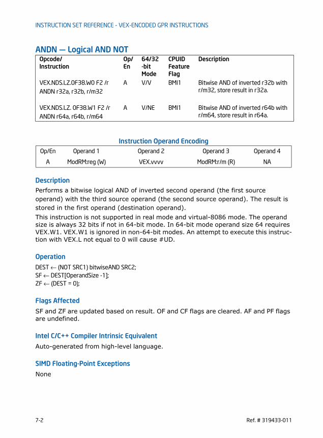
INSTRUCTION SET REFERENCE - VEX-ENCODED GPR INSTRUCTIONS
ANDN — Logical AND NOT
Instruction Operand Encoding
DescriptionPerforms a bitwise logical AND of inverted second operand (the first source operand) with the third source operand (the second source operand). The result is stored in the first operand (destination operand).This instruction is not supported in real mode and virtual-8086 mode. The operand size is always 32 bits if not in 64-bit mode. In 64-bit mode operand size 64 requires VEX.W1. VEX.W1 is ignored in non-64-bit modes. An attempt to execute this instruc-tion with VEX.L not equal to 0 will cause #UD.
Operation
DEST ← (NOT SRC1) bitwiseAND SRC2;SF ← DEST[OperandSize -1];ZF ← (DEST = 0);
Flags Affected
SF and ZF are updated based on result. OF and CF flags are cleared. AF and PF flags are undefined.
Intel C/C++ Compiler Intrinsic Equivalent
Auto-generated from high-level language.
SIMD Floating-Point Exceptions
None
Opcode/Instruction
Op/ En
64/32-bit Mode
CPUID Feature Flag
Description
VEX.NDS.LZ.0F38.W0 F2 /r A V/V BMI1 Bitwise AND of inverted r32b with r/m32, store result in r32a.ANDN r32a, r32b, r/m32
VEX.NDS.LZ. 0F38.W1 F2 /r A V/NE BMI1 Bitwise AND of inverted r64b with r/m64, store result in r64a.ANDN r64a, r64b, r/m64
Op/En Operand 1 Operand 2 Operand 3 Operand 4
A ModRM:reg (W) VEX.vvvv ModRM:r/m (R) NA
7-2 Ref. # 319433-011

INSTRUCTION SET REFERENCE - VEX-ENCODED GPR INSTRUCTIONS
Other ExceptionsSee Table 2-22.
Ref. # 319433-011 7-3

INSTRUCTION SET REFERENCE - VEX-ENCODED GPR INSTRUCTIONS
BEXTR — Bit Field Extract
Instruction Operand Encoding
Description
Extracts contiguous bits from the first source operand (the second operand) using an index value and length value specified in the second source operand (the third operand). Bit 7:0 of the first source operand specifies the starting bit position of bit extraction. A START value exceeding the operand size will not extract any bits from the second source operand. Bit 15:8 of the second source operand specifies the maximum number of bits (LENGTH) beginning at the START position to extract. Only bit positions up to (OperandSize -1) of the first source operand are extracted. The extracted bits are written to the destination register, starting from the least signifi-cant bit. All higher order bits in the destination operand (starting at bit position LENGTH) are zeroed. The destination register is cleared if no bits are extracted.This instruction is not supported in real mode and virtual-8086 mode. The operand size is always 32 bits if not in 64-bit mode. In 64-bit mode operand size 64 requires VEX.W1. VEX.W1 is ignored in non-64-bit modes. An attempt to execute this instruc-tion with VEX.L not equal to 0 will cause #UD.
Operation
START ← SRC2[7:0];LEN ← SRC2[15:8];TEMP ← ZERO_EXTEND_TO_512 (SRC1 );DEST ← ZERO_EXTEND(TEMP[START+LEN -1: START]);ZF ← (DEST = 0);
Opcode/Instruction
Op/ En
64/32-bit Mode
CPUID Feature Flag
Description
VEX.NDS1.LZ.0F38.W0 F7 /r
NOTES:
1. ModRM:r/m is used to encode the first source operand (second operand) and VEX.vvvv encodes thesecond source operand (third operand).
A V/V BMI1 Contiguous bitwise extract from r/m32 using r32b as control; store result in r32a.
BEXR r32a, r/m32, r32b
VEX.NDS1.LZ.0F38.W1 F7 /r A V/N.E. BMI1 Contiguous bitwise extract from r/m64 using r64b as control; store result in r64a
BEXR r64a, r/m64, r64b
Op/En Operand 1 Operand 2 Operand 3 Operand 4
A ModRM:reg (W) ModRM:r/m (R) VEX.vvvv (R) NA
7-4 Ref. # 319433-011

INSTRUCTION SET REFERENCE - VEX-ENCODED GPR INSTRUCTIONS
Flags AffectedZF is updated based on the result. AF, SF, and PF are undefined. All other flags are cleared.
Intel C/C++ Compiler Intrinsic Equivalent
BEXTRunsigned __int32 _bextr_u32(unsigned __int32 src, unsigned __int32 start. unsigned __int32 len);
BEXTRunsigned __int64 _bextr_u64(unsigned __int64 src, unsigned __int32 start. unsigned __int32 len);
SIMD Floating-Point Exceptions
None
Other ExceptionsSee Table 2-22.
Ref. # 319433-011 7-5

INSTRUCTION SET REFERENCE - VEX-ENCODED GPR INSTRUCTIONS
BLSI — Extract Lowest Set Isolated Bit
Instruction Operand Encoding
Description
Extracts the lowest set bit from the source operand and set the corresponding bit in the destination register. All other bits in the destination operand are zeroed. If no bits are set in the source operand, BLSI sets all the bits in the destination to 0 and sets ZF and CF.This instruction is not supported in real mode and virtual-8086 mode. The operand size is always 32 bits if not in 64-bit mode. In 64-bit mode operand size 64 requires VEX.W1. VEX.W1 is ignored in non-64-bit modes. An attempt to execute this instruc-tion with VEX.L not equal to 0 will cause #UD.
Operation
temp ← (-SRC) bitwiseAND (SRC); SF ← temp[OperandSize -1];ZF ← (temp = 0);IF SRC = 0
CF ← 0;ELSE
CF ← 1;FIDEST ← temp;
Flags AffectedZF and SF are updated based on the result. CF is set if the source is not zero. OF flags are cleared. AF and PF flags are undefined.
Opcode/Instruction
Op/ En
64/32-bit Mode
CPUID Feature Flag
Description
VEX.NDD.LZ.0F38.W0 F3 /3 A V/V BMI1 Extract lowest set bit from r/m32 and set that bit in r32.BLSI r32, r/m32
VEX.NDD.LZ.0F38.W1 F3 /3 A V/N.E. BMI1 Extract lowest set bit from r/m64, and set that bit in r64.BLSI r64, r/m64
Op/En Operand 1 Operand 2 Operand 3 Operand 4
A VEX.vvvv (W) ModRM:r/m (R) NA NA
7-6 Ref. # 319433-011

INSTRUCTION SET REFERENCE - VEX-ENCODED GPR INSTRUCTIONS
Intel C/C++ Compiler Intrinsic Equivalent
BLSI unsigned __int32 _blsi_u32(unsigned __int32 src);
BLSI unsigned __int64 _blsi_u64(unsigned __int64 src);
SIMD Floating-Point Exceptions
None
Other ExceptionsSee Table 2-22.
Ref. # 319433-011 7-7

INSTRUCTION SET REFERENCE - VEX-ENCODED GPR INSTRUCTIONS
BLSMSK — Get Mask Up to Lowest Set Bit
Instruction Operand Encoding
Description
Sets all the lower bits of the destination operand to “1” up to and including lowest set bit (=1) in the source operand. If source operand is zero, BLSMSK sets all bits of the destination operand to 1 and also sets CF to 1.This instruction is not supported in real mode and virtual-8086 mode. The operand size is always 32 bits if not in 64-bit mode. In 64-bit mode operand size 64 requires VEX.W1. VEX.W1 is ignored in non-64-bit modes. An attempt to execute this instruc-tion with VEX.L not equal to 0 will cause #UD.
Operation
temp ← (SRC-1) XOR (SRC) ;SF ← temp[OperandSize -1];ZF ← 0;IF SRC = 0
CF ← 1;ELSE
CF ← 0;FIDEST ← temp;
Flags Affected
SF is updated based on the result. CF is set if the source if zero. ZF and OF flags are cleared. AF and PF flag are undefined.
Opcode/Instruction
Op/ En
64/32-bit Mode
CPUID Feature Flag
Description
VEX.NDD.LZ.0F38.W0 F3 /2 A V/V BMI1 Set all lower bits in r32 to “1” start-ing from bit 0 to lowest set bit in r/m32.
BLSMSK r32, r/m32
VEX.NDD.LZ.0F38.W1 F3 /2 A V/N.E. BMI1 Set all lower bits in r64 to “1” start-ing from bit 0 to lowest set bit in r/m64.
BLSMSK r64, r/m64
Op/En Operand 1 Operand 2 Operand 3 Operand 4
A VEX.vvvv (W) ModRM:r/m (R) NA NA
7-8 Ref. # 319433-011

INSTRUCTION SET REFERENCE - VEX-ENCODED GPR INSTRUCTIONS
Intel C/C++ Compiler Intrinsic Equivalent
BLSMSK unsigned __int32 _blsmsk_u32(unsigned __int32 src);
BLSMSK unsigned __int64 _blsmsk_u64(unsigned __int64 src);
SIMD Floating-Point Exceptions
None
Other ExceptionsSee Table 2-22.
Ref. # 319433-011 7-9

INSTRUCTION SET REFERENCE - VEX-ENCODED GPR INSTRUCTIONS
BLSR- Reset Lowest Set Bit
Instruction Operand Encoding
Description
Copies all bits from the source operand to the destination operand and resets (=0) the bit position in the destination operand that corresponds to the lowest set bit of the source operand. If the source operand is zero BLSR sets CF.This instruction is not supported in real mode and virtual-8086 mode. The operand size is always 32 bits if not in 64-bit mode. In 64-bit mode operand size 64 requires VEX.W1. VEX.W1 is ignored in non-64-bit modes. An attempt to execute this instruc-tion with VEX.L not equal to 0 will cause #UD.
Operation
temp ← (SRC-1) bitwiseAND ( SRC );SF ← temp[OperandSize -1];ZF ← (temp = 0);IF SRC = 0
CF ← 1;ELSE
CF ← 0;FIDEST ← temp;
Flags Affected
ZF and SF flags are updated based on the result. CF is set if the source is zero. OF flag is cleared. AF and PF flags are undefined.
Opcode/Instruction
Op/ En
64/32-bit Mode
CPUID Feature Flag
Description
VEX.NDD.LZ.0F38.W0 F3 /1 A V/V BMI1 Reset lowest set bit of r/m32, keep all other bits of r/m32 and write result to r32.
BLSR r32, r/m32
VEX.NDD.LZ.0F38.W1 F3 /1 A V/N.E. BMI1 Reset lowest set bit of r/m64, keep all other bits of r/m64 and write result to r64.
BLSR r64, r/m64
Op/En Operand 1 Operand 2 Operand 3 Operand 4
A VEX.vvvv (W) ModRM:r/m (R) NA NA
7-10 Ref. # 319433-011

INSTRUCTION SET REFERENCE - VEX-ENCODED GPR INSTRUCTIONS
Intel C/C++ Compiler Intrinsic Equivalent
BLSR unsigned __int32 _blsr_u32(unsigned __int32 src);
BLSR unsigned __int64 _blsr_u64(unsigned __int64 src);
SIMD Floating-Point Exceptions
None
Other ExceptionsSee Table 2-22.
Ref. # 319433-011 7-11
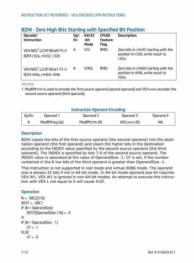
INSTRUCTION SET REFERENCE - VEX-ENCODED GPR INSTRUCTIONS
BZHI - Zero High Bits Starting with Specified Bit Position
Instruction Operand Encoding
Description
BZHI copies the bits of the first source operand (the second operand) into the desti-nation operand (the first operand) and clears the higher bits in the destination according to the INDEX value specified by the second source operand (the third operand). The INDEX is specified by bits 7:0 of the second source operand. The INDEX value is saturated at the value of OperandSize -1. CF is set, if the number contained in the 8 low bits of the third operand is greater than OperandSize -1.This instruction is not supported in real mode and virtual-8086 mode. The operand size is always 32 bits if not in 64-bit mode. In 64-bit mode operand size 64 requires VEX.W1. VEX.W1 is ignored in non-64-bit modes. An attempt to execute this instruc-tion with VEX.L not equal to 0 will cause #UD.
Operation
N ← SRC2[7:0]DEST ← SRC1IF (N < OperandSize)
DEST[OperandSize-1:N] ← 0FIIF (N > OperandSize - 1)
CF ← 1ELSE
CF ← 0
Opcode/Instruction
Op/ En
64/32-bit Mode
CPUID Feature Flag
Description
VEX.NDS1.LZ.0F38.W0 F5 /r
NOTES:
1. ModRM:r/m is used to encode the first source operand (second operand) and VEX.vvvv encodes thesecond source operand (third operand).
A V/V BMI2 Zero bits in r/m32 starting with the position in r32b, write result to r32a.
BZHI r32a, r/m32, r32b
VEX.NDS1.LZ.0F38.W1 F5 /r A V/N.E. BMI2 Zero bits in r/m64 starting with the position in r64b, write result to r64a.
BZHI r64a, r/m64, r64b
Op/En Operand 1 Operand 2 Operand 3 Operand 4
A ModRM:reg (W) ModRM:r/m (R) VEX.vvvv (R) NA
7-12 Ref. # 319433-011

INSTRUCTION SET REFERENCE - VEX-ENCODED GPR INSTRUCTIONS
FI
Flags Affected
ZF, CF and SF flags are updated based on the result. OF flag is cleared. AF and PF flags are undefined.
Intel C/C++ Compiler Intrinsic Equivalent
BZHI unsigned __int32 _bzhi_u32(unsigned __int32 src, unsigned __int32 index);
BZHI unsigned __int64 _bzhi_u64(unsigned __int64 src, unsigned __int32 index);
SIMD Floating-Point Exceptions
None
Other ExceptionsSee Table 2-22.
Ref. # 319433-011 7-13

INSTRUCTION SET REFERENCE - VEX-ENCODED GPR INSTRUCTIONS
LZCNT— Count the Number of Leading Zero Bits
Instruction Operand Encoding
Description
Counts the number of leading most significant zero bits in a source operand (second operand) returning the result into a destination (first operand). LZCNT is an extension of the BSR instruction. The key difference between LZCNT and BSR is that LZCNT provides operand size as output when source operand is zero, while in the case of BSR instruction, if source operand is zero, the content of destina-tion operand are undefined. On processors that do not support LZCNT, the instruction byte encoding is executed as BSR. In 64-bit mode 64-bit operand size requires REX.W=1.
Operation
temp ← OperandSize - 1DEST ← 0WHILE (temp >= 0) AND (Bit(SRC, temp) = 0)DO
temp ← temp - 1DEST ← DEST+ 1
OD
IF DEST = OperandSizeCF ← 1
ELSE
Opcode/Instruction
Op/ En
64/32-bit Mode
CPUID Feature Flag
Description
F3 0F BD /r A V/V LZCNT Count the number of leading zero bits in r/m16, return result in r16.LZCNT r16, r/m16
F3 0F BD /r A V/V LZCNT Count the number of leading zero bits in r/m32, return result in r32.LZCNT r32, r/m32
REX.W + F3 0F BD /r A V/N.E. LZCNT Count the number of leading zero bits in r/m64, return result in r64.LZCNT r64, r/m64
Op/En Operand 1 Operand 2 Operand 3 Operand 4
A ModRM:reg (W) ModRM:r/m (R) NA NA
7-14 Ref. # 319433-011

INSTRUCTION SET REFERENCE - VEX-ENCODED GPR INSTRUCTIONS
CF ← 0FI
IF DEST = 0ZF ← 1
ELSEZF ← 0
FI
Flags Affected
ZF flag is set to 1 in case of zero output (most significant bit of the source is set), and to 0 otherwise, CF flag is set to 1 if input was zero and cleared otherwise. OF, SF, PF and AF flags are undefined.
Intel C/C++ Compiler Intrinsic Equivalent
LZCNT unsigned __int32 _lzcnt_u32(unsigned __int32 src);
LZCNT unsigned __int64 _lzcnt_u64(unsigned __int64 src);
SIMD Floating-Point Exceptions
None
Other Exceptions
See Table 2-21.
Ref. # 319433-011 7-15

INSTRUCTION SET REFERENCE - VEX-ENCODED GPR INSTRUCTIONS
MULX — Unsigned Multiply Without Affecting Flags
Instruction Operand Encoding
Description
Performs an unsigned multiplication of the implicit source operand (EDX/RDX) and the specified source operand (the third operand) and stores the low half of the result in the second destination (second operand), the high half of the result in the first destination operand (first operand), without reading or writing the arithmetic flags. This enables efficient programming where the software can interleave add with carry operations and multiplications. If the first and second operand are identical, it will contain the high half of the multi-plication result.This instruction is not supported in real mode and virtual-8086 mode. The operand size is always 32 bits if not in 64-bit mode. In 64-bit mode operand size 64 requires VEX.W1. VEX.W1 is ignored in non-64-bit modes. An attempt to execute this instruc-tion with VEX.L not equal to 0 will cause #UD.
Operation
// DEST1: ModRM:reg// DEST2: VEX.vvvvIF (OperandSize = 32)
SRC1 ← EDX;DEST2 ← (SRC1*SRC2)[31:0];DEST1 ← (SRC1*SRC2)[63:32];
ELSE IF (OperandSize = 64)SRC1 ← RDX;
DEST2 ← (SRC1*SRC2)[63:0];
Opcode/Instruction
Op/ En
64/32-bit Mode
CPUID Feature Flag
Description
VEX.NDD.LZ.F2.0F38.W0 F6 /r A V/V BMI2 Unsigned multiply of r/m32 with EDX without affecting arithmetic flags.
MULX r32a, r32b, r/m32
VEX.NDD.LZ.F2.0F38.W1 F6 /r A V/N.E. BMI2 Unsigned multiply of r/m64 with RDX without affecting arithmetic flags.
MULX r64a, r64b, r/m64
Op/En Operand 1 Operand 2 Operand 3 Operand 4
A ModRM:reg (W) VEX.vvvv (W) ModRM:r/m (R)RDX/EDX is implied 64/32
bits source
7-16 Ref. # 319433-011

INSTRUCTION SET REFERENCE - VEX-ENCODED GPR INSTRUCTIONS
DEST1 ← (SRC1*SRC2)[127:64];FI
Flags AffectedNone
Intel C/C++ Compiler Intrinsic Equivalent
Auto-generated from high-level language.
SIMD Floating-Point Exceptions
None
Other Exceptions
See Table 2-22.
Ref. # 319433-011 7-17

INSTRUCTION SET REFERENCE - VEX-ENCODED GPR INSTRUCTIONS
PDEP — Parallel Bits Deposit
Instruction Operand Encoding
Description
PDEP uses a mask in the second source operand (the third operand) to transfer/scatter contiguous low order bits in the first source operand (the second operand) into the destination (the first operand). PDEP takes the low bits from the first source operand and deposit them in the destination operand at the corre-sponding bit locations that are set in the second source operand (mask). All other bits (bits not set in mask) in destination are set to zero.
Figure 7-1. PDEP Example
Opcode/Instruction
Op/ En
64/32-bit Mode
CPUID Feature Flag
Description
VEX.NDS.LZ.F2.0F38.W0 F5 /r A V/V BMI2 Parallel deposit of bits from r32b using mask in r/m32, result is writ-ten to r32a.
PDEP r32a, r32b, r/m32
VEX.NDS.LZ.F2.0F38.W1 F5 /r A V/N.E. BMI2 Parallel deposit of bits from r64b using mask in r/m64, result is writ-ten to r64a
PDEP r64a, r64b, r/m64
Op/En Operand 1 Operand 2 Operand 3 Operand 4
A ModRM:reg (W) VEX.vvvv (R) ModRM:r/m (R) NA
0010010101000
00000000 0DEST
SRC1
SRC2(mask)
S31 S30 S29 S28 S27 S7 S6 S5 S3S4 S2 S1 S0
S0S1S2S3
bit 0bit 31
7-18 Ref. # 319433-011
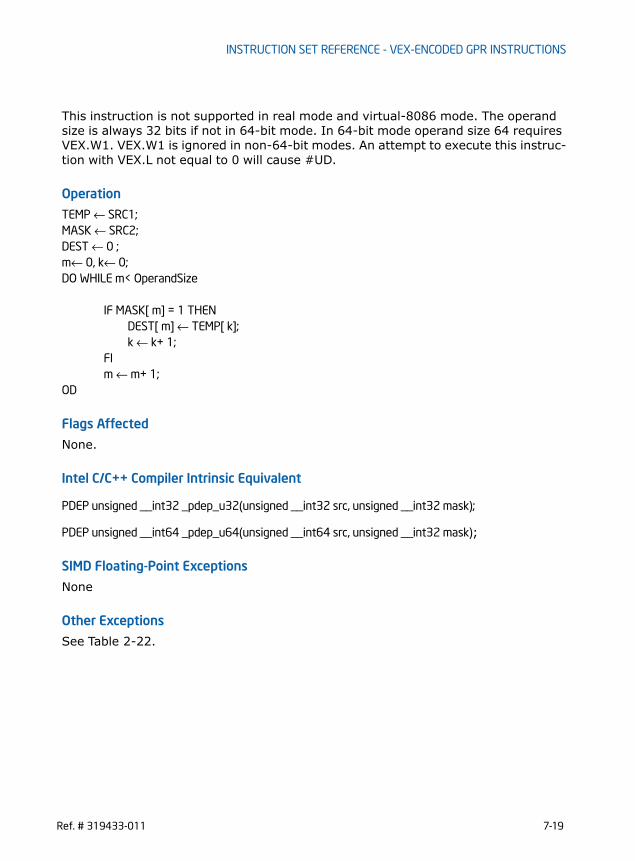
INSTRUCTION SET REFERENCE - VEX-ENCODED GPR INSTRUCTIONS
This instruction is not supported in real mode and virtual-8086 mode. The operand size is always 32 bits if not in 64-bit mode. In 64-bit mode operand size 64 requires VEX.W1. VEX.W1 is ignored in non-64-bit modes. An attempt to execute this instruc-tion with VEX.L not equal to 0 will cause #UD.
Operation
TEMP ← SRC1;MASK ← SRC2;DEST ← 0 ;m← 0, k← 0;DO WHILE m< OperandSize
IF MASK[ m] = 1 THENDEST[ m] ← TEMP[ k];
k ← k+ 1;FIm ← m+ 1;
OD
Flags Affected
None.
Intel C/C++ Compiler Intrinsic Equivalent
PDEP unsigned __int32 _pdep_u32(unsigned __int32 src, unsigned __int32 mask);
PDEP unsigned __int64 _pdep_u64(unsigned __int64 src, unsigned __int32 mask);
SIMD Floating-Point Exceptions
None
Other Exceptions
See Table 2-22.
Ref. # 319433-011 7-19

INSTRUCTION SET REFERENCE - VEX-ENCODED GPR INSTRUCTIONS
PEXT— Parallel Bits Extract
Instruction Operand Encoding
Description
PEXT uses a mask in the second source operand (the third operand) to transfer either contiguous or non-contiguous bits in the first source operand (the second operand) to contiguous low order bit positions in the destination (the first operand). For each bit set in the MASK, PEXT extracts the corresponding bits from the first source operand and writes them into contiguous lower bits of destination operand. The remaining upper bits of destination are zeroed.
Figure 7-2. PEXT Example
Opcode/Instruction
Op/ En
64/32-bit Mode
CPUID Feature Flag
Description
VEX.NDS.LZ.F3.0F38.W0 F5 /r A V/V BMI2 Parallel extract of bits from r32b using mask in r/m32, result is writ-ten to r32a.
PEXT r32a, r32b, r/m32
VEX.NDS.LZ.F3.0F38.W1 F5 /r A V/N.E. BMI2 Parallel extract of bits from r64b using mask in r/m64, result is writ-ten to r64a.
PEXT r64a, r64b, r/m64
Op/En Operand 1 Operand 2 Operand 3 Operand 4
A ModRM:reg (W) VEX.vvvv (R) ModRM:r/m (R) NA
DEST
SRC1
SRC2(mask)
S31 S30 S29 S28 S27 S7 S6 S5 S3S4 S2 S1 S0
001010101000
S2S5S7000000000
0
S28
bit 0bit 31
7-20 Ref. # 319433-011

INSTRUCTION SET REFERENCE - VEX-ENCODED GPR INSTRUCTIONS
This instruction is not supported in real mode and virtual-8086 mode. The operand size is always 32 bits if not in 64-bit mode. In 64-bit mode operand size 64 requires VEX.W1. VEX.W1 is ignored in non-64-bit modes. An attempt to execute this instruc-tion with VEX.L not equal to 0 will cause #UD.
Operation
TEMP ← SRC1;MASK ← SRC2;DEST ← 0 ;m← 0, k← 0;DO WHILE m< OperandSize
IF MASK[ m] = 1 THENDEST[ k] ← TEMP[ m];
k ← k+ 1;FIm ← m+ 1;
OD
Flags Affected
None.
Intel C/C++ Compiler Intrinsic Equivalent
PEXT unsigned __int32 _pext_u32(unsigned __int32 src, unsigned __int32 mask);
PEXT unsigned __int64 _pext_u64(unsigned __int64 src, unsigned __int32 mask);
SIMD Floating-Point Exceptions
None
Other Exceptions
See Table 2-22.
Ref. # 319433-011 7-21

INSTRUCTION SET REFERENCE - VEX-ENCODED GPR INSTRUCTIONS
RORX — Rotate Right Logical Without Affecting Flags
Instruction Operand Encoding
Description
Rotates the bits of second operand right by the count value specified in imm8 without affecting arithmetic flags. The RORX instruction does not read or write the arithmetic flags.This instruction is not supported in real mode and virtual-8086 mode. The operand size is always 32 bits if not in 64-bit mode. In 64-bit mode operand size 64 requires VEX.W1. VEX.W1 is ignored in non-64-bit modes. An attempt to execute this instruc-tion with VEX.L not equal to 0 will cause #UD.
Operation
IF (OperandSize = 32)y ← imm8 AND 1FH;DEST ← (SRC >> y) | (SRC << (32-y));
ELSEIF (OperandSize = 64 ) y ← imm8 AND 3FH;DEST ← (SRC >> y) | (SRC << (64-y));
ENDIF
Flags AffectedNone
Intel C/C++ Compiler Intrinsic Equivalent
Auto-generated from high-level language.
Opcode/Instruction
Op/ En
64/32-bit Mode
CPUID Feature Flag
Description
VEX.LZ.F2.0F3A.W0 F0 /r ib A V/V BMI2 Rotate 32-bit r/m32 right imm8 times without affecting arith-metic flags.
RORX r32, r/m32, imm8
VEX.LZ.F2.0F3A.W1 F0 /r ib A V/N.E. BMI2 Rotate 64-bit r/m64 right imm8 times without affecting arith-metic flags.
RORX r64, r/m64, imm8
Op/En Operand 1 Operand 2 Operand 3 Operand 4
A ModRM:reg (W) ModRM:r/m (R) NA NA
7-22 Ref. # 319433-011

INSTRUCTION SET REFERENCE - VEX-ENCODED GPR INSTRUCTIONS
SIMD Floating-Point Exceptions
None
Other Exceptions
See Table 2-22.
Ref. # 319433-011 7-23

INSTRUCTION SET REFERENCE - VEX-ENCODED GPR INSTRUCTIONS
SARX/SHLX/SHRX- Shift Without Affecting Flags
Instruction Operand Encoding
Description
Shifts the bits of the first source operand (the second operand) to the left or right by a COUNT value specified in the second source operand (the third operand). The result is written to the destination operand (the first operand).The shift arithmetic right (SARX) and shift logical right (SHRX) instructions shift the bits of the destination operand to the right (toward less significant bit locations), SARX keeps and propagates the most significant bit (sign bit) while shifting.The logical shift left (SHLX) shifts the bits of the destination operand to the left (toward more significant bit locations).
Opcode/Instruction
Op/ En
64/32-bit Mode
CPUID Feature Flag
Description
VEX.NDS1.LZ.F3.0F38.W0 F7 /r
NOTES:
1. ModRM:r/m is used to encode the first source operand (second operand) and VEX.vvvv encodes thesecond source operand (third operand).
A V/V BMI2 Shift r/m32 arithmetically right with count specified in r32b.SARX r32a, r/m32, r32b
VEX.NDS1.LZ.66.0F38.W0 F7 /r A V/V BMI2 Shift r/m32 logically left with count specified in r32b.SHLX r32a, r/m32, r32b
VEX.NDS1.LZ.F2.0F38.W0 F7 /r A V/V BMI2 Shift r/m32 logically right with count specified in r32b.SHRX r32a, r/m32, r32b
VEX.NDS1.LZ.F3.0F38.W1 F7 /r A V/N.E. BMI2 Shift r/m64 arithmetically right with count specified in r64b.SARX r64a, r/m64, r64b
VEX.NDS1.LZ.66.0F38.W1 F7 /r A V/N.E. BMI2 Shift r/m64 logically left with count specified in r64b.SHLX r64a, r/m64, r64b
VEX.NDS1.LZ.F2.0F38.W1 F7 /r A V/N.E. BMI2 Shift r/m64 logically right with count specified in r64b.SHRX r64a, r/m64, r64b
Op/En Operand 1 Operand 2 Operand 3 Operand 4
A ModRM:reg (W) ModRM:r/m (R) VEX.vvvv (R) NA
7-24 Ref. # 319433-011

INSTRUCTION SET REFERENCE - VEX-ENCODED GPR INSTRUCTIONS
This instruction is not supported in real mode and virtual-8086 mode. The operand size is always 32 bits if not in 64-bit mode. In 64-bit mode operand size 64 requires VEX.W1. VEX.W1 is ignored in non-64-bit modes. An attempt to execute this instruc-tion with VEX.L not equal to 0 will cause #UD.If the value specified in the first source operand exceeds OperandSize -1, the COUNT value is masked.SARX,SHRX, and SHLX instructions do not update flags.
Operation
TEMP ← SRC1;IF VEX.W1 and CS.L = 1THEN
countMASK ←3FH;ELSE
countMASK ←1FH;FICOUNT ← (SRC2 AND countMASK)
DEST[OperandSize -1] = TEMP[OperandSize -1];DO WHILE (COUNT != 0)
IF instruction is SHLXTHEN
DEST[] ← DEST *2;ELSE IF instruction is SHRX
THENDEST[] ← DEST /2; //unsigned divide
; ELSE // SARXDEST[] ← DEST /2; // signed divide, round toward negative infinity
FI;COUNT ← COUNT - 1;
OD
Flags Affected
None.
Intel C/C++ Compiler Intrinsic Equivalent
Auto-generated from high-level language.
SIMD Floating-Point Exceptions
None
Ref. # 319433-011 7-25

INSTRUCTION SET REFERENCE - VEX-ENCODED GPR INSTRUCTIONS
Other ExceptionsSee Table 2-22.
7-26 Ref. # 319433-011

INSTRUCTION SET REFERENCE - VEX-ENCODED GPR INSTRUCTIONS
TZCNT — Count the Number of Trailing Zero Bits
Instruction Operand Encoding
Description
TZCNT counts the number of trailing least significant zero bits in source operand (second operand) and returns the result in destination operand (first operand). TZCNT is an extension of the BSF instruction. The key difference between TZCNT and BSF instruction is that TZCNT provides operand size as output when source operand is zero while in the case of BSF instruction, if source operand is zero, the content of destination operand are undefined. On processors that do not support TZCNT, the instruction byte encoding is executed as BSF.
Operation
temp ← 0DEST ← 0DO WHILE ( (temp < OperandSize) and (SRC[ temp] = 0) )
temp ← temp +1DEST ← DEST+ 1
OD
IF DEST = OperandSizeCF ← 1
ELSECF ← 0
FI
Opcode/Instruction
Op/ En
64/32-bit Mode
CPUID Feature Flag
Description
F3 0F BC /r A V/V BMI1 Count the number of trailing zero bits in r/m16, return result in r16.TZCNT r16, r/m16
F3 0F BC /r A V/V BMI1 Count the number of trailing zero bits in r/m32, return result in r32TZCNT r32, r/m32
REX.W + F3 0F BC /r A V/N.E. BMI1 Count the number of trailing zero bits in r/m64, return result in r64.TZCNT r64, r/m64
Op/En Operand 1 Operand 2 Operand 3 Operand 4
A ModRM:reg (W) ModRM:r/m (R) NA NA
Ref. # 319433-011 7-27

INSTRUCTION SET REFERENCE - VEX-ENCODED GPR INSTRUCTIONS
IF DEST = 0ZF ← 1
ELSEZF ← 0
FI
Flags Affected
ZF is set to 1 in case of zero output (least significant bit of the source is set), and to 0 otherwise, CF is set to 1 if the input was zero and cleared otherwise. OF, SF, PF and AF flags are undefined.
Intel C/C++ Compiler Intrinsic Equivalent
TZCNT unsigned __int32 _tzcnt_u32(unsigned __int32 src);
TZCNT unsigned __int64 _tzcnt_u64(unsigned __int64 src);
SIMD Floating-Point Exceptions
None
Other Exceptions
See Table 2-21.
7-28 Ref. # 319433-011

INSTRUCTION SET REFERENCE - VEX-ENCODED GPR INSTRUCTIONS
INVPCID - Invalidate Processor Context ID
Instruction Operand Encoding
Description
Invalidates mappings in the translation lookaside buffers (TLBs) and paging-struc-ture caches based on the invalidation type specified in the first operand and processor context identifier (PCID) invalidate descriptor specified in the second operand. The INVPCID descriptor is specified as a 16-byte memory operand and has no alignment restriction. The layout of the INVPCID descriptor is shown in Figure 7-3. In 64-bit mode the linear address field (bits 127:64) in the INVPCID descriptor must satisfy canonical requirement unless the linear address field is ignored.
Outside IA-32e mode, the register operand is always 32 bits, regardless of the value of CS.D. In 64-bit mode the register operand has 64 bits; however, if bits 63:32 of the register operand are not zero, INVPCID fails due to an attempt to use an unsup-ported INVPCID type (see below).
Opcode/Instruction
Op/ En
64/32-bit Mode
CPUID Feature Flag
Description
66 0F 38 82 /r A NE/V INVPCID Invalidates entries in the TLBs and paging-structure caches based on invalidation type in r32 and descriptor in m128.
INVPCID r32, m128
66 0F 38 82 /r A V/NE INVPCID Invalidates entries in the TLBs and paging-structure caches based on invalidation type in r64 and descriptor in m128.
INVPCID r64, m128
Op/En Operand 1 Operand 2 Operand 3 Operand 4
A ModRM:reg (R) ModRM:r/m (R) NA NA
Figure 7-3. INVPCID Descriptor
127 64 63 01112Reserved (must be zero)Linear Address PCID
Ref. # 319433-011 7-29

INSTRUCTION SET REFERENCE - VEX-ENCODED GPR INSTRUCTIONS
The INVPCID types supported by a logical processors are:• Individual-address invalidation: If the INVPCID type is 0, the logical processor
invalidates mappings for a single linear address and tagged with the PCID specified in the INVPCID descriptor, except global translations. The instruction may also invalidate global translations, mappings for other linear addresses, or mappings tagged with other PCIDs.
• Single-context invalidation: If the INVPCID type is 1, the logical processor invalidates all mappings tagged with the PCID specified in the INVPCID descriptor except global translations. In some cases, it may invalidate mappings for other PCIDs as well.
• All-context invalidation: If the INVPCID type is 2, the logical processor invalidates all mappings tagged with any PCID.
• All-context invalidation, retaining global translations: If the INVPCID type is 3, the logical processor invalidates all mappings tagged with any PCID except global translations, ignoring the INVPCID descriptor. The instruction may also invalidate global translations as well.
If an unsupported INVPCID type is specified, or if the reserved field in the descriptor is not zero, the instruction fails.Outside IA-32e mode, the processor treats INVPCID as if all mappings are associated with PCID 000H.
Operation
INVPCID_TYPE ← value of register operand; // must be in the range of 0-3INVPCID_DESC ← value of memory operand;CASE INVPCID_TYPE OF
0: // individual-address invalidation retaining global translationsOP_PCID ← INVPCID_DESC[11:0];ADDR ← INVPCID_DESC[127:64];Invalidate mappings for ADDR tagged with OP_PCID except global translations;BREAK;
1: // single PCID invalidation retaining globalsOP_PCID ← INVPCID_DESC[11:0];Invalidate all mappings tagged with OP_PCID except global translations;BREAK;
2: // all PCID invalidationInvalidate all mappings tagged with any PCID;BREAK;
3: // all PCID invalidation retaining global translationsInvalidate all mappings tagged with any PCID except global translations;BREAK;
ESAC;
7-30 Ref. # 319433-011

INSTRUCTION SET REFERENCE - VEX-ENCODED GPR INSTRUCTIONS
Intel C/C++ Compiler Intrinsic Equivalent
INVPCID void _invpcid(unsigned __int32 type, void * descriptor);
SIMD Floating-Point Exceptions
None
Protected Mode Exceptions#GP(0) If the current privilege level is not 0.
If the memory operand effective address is outside the CS, DS, ES, FS, or GS segment limit.If the DS, ES, FS, or GS register contains an unusable segment.If the source operand is located in an execute-only code segment.If an invalid type is specified in the register operand, i.e., INVPCID_TYPE > 3.If bits 63:12 of INVPCID_DESC are not all zero.If CR4.PCIDE=0, INVPCID_DESC[11:0] is not zero, and INVPCID_TYPE is either 0, or 1.
#PF(fault-code) If a page fault occurs in accessing the memory operand.#SS(0) If the memory operand effective address is outside the SS
segment limit.If the SS register contains an unusable segment.
#UD If if CPUID.(EAX=07H, ECX=0H):EBX.INVPCID (bit 10) = 0.If the LOCK prefix is used.
Real-Address Mode Exceptions#GP(0) If an invalid type is specified in the register operand, i.e
INVPCID_TYPE > 3.If bits 63:12 of INVPCID_DESC are not all zero.If CR4.PCIDE=0, INVPCID_DESC[11:0] is not zero, and INVPCID_TYPE is either 0, or 1.
#UD If CPUID.(EAX=07H, ECX=0H):EBX.INVPCID (bit 10) = 0.If the LOCK prefix is used.
Virtual-8086 Mode Exceptions#UD The INVPCID instruction is not recognized in virtual-8086 mode.
Compatibility Mode ExceptionsSame exceptions as in protected mode.
Ref. # 319433-011 7-31

INSTRUCTION SET REFERENCE - VEX-ENCODED GPR INSTRUCTIONS
64-Bit Mode Exceptions#GP(0) If the current privilege level is not 0.
If the memory operand is in the CS, DS, ES, FS, or GS segments and the memory address is in a non-canonical form.If an invalid type is specified in the register operand.If an invalid type is specified in the register operand, i.e INVPCID_TYPE > 3.If bits 63:12 of INVPCID_DESC are not all zero.If CR4.PCIDE=0, INVPCID_DESC[11:0] is not zero, and INVPCID_TYPE is either 0, or 1.If INVPCID_TYPE is 0, INVPCID_DESC[127:64] is not a canon-ical address.
#PF(fault-code) If a page fault occurs in accessing the memory operand.#SS(0) If the memory destination operand is in the SS segment and the
memory address is in a non-canonical form.#UD If the LOCK prefix is used.
If CPUID.(EAX=07H, ECX=0H):EBX.INVPCID (bit 10) = 0.
7-32 Ref. # 319433-011

POST-32NM PROCESSOR INSTRUCTIONS
CHAPTER 8POST-32NM PROCESSOR INSTRUCTIONS
8.1 OVERVIEWThis chapter describes additional instructions targeted for Intel 64 architecture processors in process technology smaller than 32 nm. These instructions include:• Two instructions to support 16-bit floating-point data type conversion to and from
single-precision floating-point type. Conversion to packed 16-bit floating-point values from packed single-precision floating-point values also provides rounding control using an immediate byte. These float-16 instructions convert packed data types of different sizes following the same manner as the 256-bit vector SIMD extension, AVX.
• One instruction that generates random numbers of 16/32/64 bit wide random integers. The random number generator instruction operates on general-purpose registers.
• Four instructions that allow software working in 64-bit environment to read and write FS base and GS base registers in all privileged levels.
8.2 CPUID DETECTION OF NEW INSTRUCTIONSApplication using float 16 instruction must follow a detection sequence similar to AVX to ensure:• The OS has enabled YMM state management support,• The processor support AVX as indicated by the CPUID feature flag, i.e.
CPUID.01H:ECX.AVX[bit 28] = 1.• The processor support 16-bit floating-point conversion instructions via a CPUID
feature flag (CPUID.01H:ECX.F16C[bit 29] = 1).Application detection of Float-16 conversion instructions follow the general proce-dural flow in Figure 8-1.
Ref. # 319433-011 8-1

POST-32NM PROCESSOR INSTRUCTIONS
----------------------------------------------------------------------------------------INT supports_f16c(){ ; result in eax
mov eax, 1cpuidand ecx, 038000000Hcmp ecx, 038000000H; check OSXSAVE, AVX, F16C feature flags jne not_supported; processor supports AVX,F16C instructions and XGETBV is enabled by OSmov ecx, 0; specify 0 for XFEATURE_ENABLED_MASK registerXGETBV; result in EDX:EAXand eax, 06Hcmp eax, 06H; check OS has enabled both XMM and YMM state supportjne not_supportedmov eax, 1jmp doneNOT_SUPPORTED:mov eax, 0done:
Figure 8-1. General Procedural Flow of Application Detection of Float-16
Implied HW support for
Check enabled YMM state inXFEM via XGETBV
Check feature flags
for AVX and F16C
Check feature flag
CPUID.1H:ECX.OXSAVE = 1?
OS provides processorextended state management
State ok to use
XSAVE, XRSTOR, XGETBV, XFEATURE_ENABLED_MASK
enabled Instructions
Yes
8-2 Ref. # 319433-011

POST-32NM PROCESSOR INSTRUCTIONS
}-------------------------------------------------------------------------------
RDRAND, RDFSBASE/RDGSBASE, WRFSBASE/WRGSBASE operates on general purpose registers only. Before software attempts to use the RDRAND instruction, it must check that the CPUID feature flag indicating processor supports RDRAND, i.e., if CPUID.01H:ECX.RDRAND[bit 30] = 1.CPUID.(EAX=07H, ECX=0H):EBX.FSGSBASE[bit 0] = 1 indicates availability of instructions that are primarily targeting use by system software manipulating the base of FS and GS segments. These instructions require enabling by OS (see Section 8.5). An OS may provide programming interfaces indicating its support of application use of RDFSBASE/RDGSBASE, WRFSBASE/WRGSBASE instructions.
8.3 16-BIT FLOATING-POINT DATA TYPE SUPPORTTwo new instructions support half-precision floating-point data type with conversion to and from single-precision floating-point data types. Table 8-1 gives the length, precision, and approximate normalized range that can be represented by half and single precision data types. Denormal values are also supported in these types.
Table 8-2 shows the floating-point encodings for zeros, denormalized finite numbers, normalized finite numbers, infinities, and NaNs for each of the three floating-point data types.
Table 8-1. Length, Precision, and Range of Floating-Point Data TypesData Type Length Precision
(Bits)Approximate Normalized Range
Binary Decimal
Half Precision 16 11 2–14 to 215 3.1 × 10⁻⁵ to 6.50 × 10⁴
Single Precision 32 24 2–126 to 2127 1.18 × 10–38 to 3.40 × 1038
Double Precision 64 53 2–1022 to 21023 2.23 × 10–308 to 1.79 × 10308
Ref. # 319433-011 8-3

POST-32NM PROCESSOR INSTRUCTIONS
Table 8-2. Half-Precision Floating-Point Number and NaN Encodings
Class Sign Biased Exponent Significand
Integer1 Fraction
Positive +∞ 0 11..11 1 00..00
+Normals 0..0
11..10 . .
00..01
1..1
11..11 . .
00..00
+Denormals 0..0
00..00 . .
00..00
0..0
11.11 . .
00..01
+Zero 0 00..00 0 00..00
Negative −Zero 1 00..00 0 00..00
−Denormals 1..1
00..00 . .
00..00
0..0
00..01 . .
11..11
−Normals 1..1
00..01 . .
11..10
1..1
00..00 . .
11..11
-• 1 11..11 1 00..00
NaNs SNaN X 11..11 1 0X..XX2
QNaN X 11..11 1 1X..XX
QNaN Floating-Point Indefinite
1 11..11 1 10..00
Half-Precision:Single-Precision;Double-Precision;
← 5Bits →← 8 Bits →← 11 Bits →
← 10 Bits →← 23Bits →← 52Bits →
NOTES:1. Integer bit is implied and not stored in memory format.2. The fraction for SNaN encodings must be non-zero with the most-significant bit 0.3. The most-significant bit of the fraction for QNaN encoding must be 1.
8-4 Ref. # 319433-011

POST-32NM PROCESSOR INSTRUCTIONS
Half-precision floating-point data type consists of a sign bit, a 5-bit exponent field, and a 11-bit significand field. The 11-bit significand consists of an implied integer bit that is not stored and a 10-bit fraction field that is stored as the 10 least-significant bits along with the sign bit (bit 15) and the exponent field (bits 14:10), see Figure 8-2.
The exponent of each floating-point data type is encoded in biased format, the bias constant is 15 for half-precision floating-point data type. When storing floating-point values in memory, half-precision values are stored in 2 consecutive bytes in memory. Table 8-3 shows how the real number 178.125 (in ordinary decimal format) is stored in IEEE Standard 754 floating-point format. The table lists a progression of real number notations that leads to the half-precision, 16-bit floating-point format.
Figure 8-2. Floating-Point Data Types
Table 8-3. Real and Floating-Point Number Notation
Notation Value
Ordinary Decimal 178.125
Scientific Decimal 1.78125E10 2
Scientific Binary 1.0110010001E2111
Scientific Binary(Biased Exponent)
1.0110010001E210110
Half-Precision Format Sign Biased Exponent Normalized Significand
0 10110 0110010001 1. (Implied)
022
015 14
Sign
0
233031
51526263
Single PrecisionFloating-Point
Double PrecisionFloating-Point
Sign
Sign
9
Half PrecisionFloating-Point
Ref. # 319433-011 8-5

POST-32NM PROCESSOR INSTRUCTIONS
8.3.1 Half-Precision Floating-Point Conversion Half-precision floating-point values are not used by the processor directly for arith-metic operations. Two instructions, VCVTPH2PS, VCVTPS2PH, provide conversion between half-precision and single-precision floating-point values. The conversion operations of VCVTPS2PH allow programmer to specify rounding control using control fields in an immediate byte. The effects of the immediate byte are listed in Table 8-4. Rounding control can use Imm[2] to select an override RC field specified in Imm[1:0] or use MXCSR setting.
VCVTPH2PS and VCVTPS2PH are subject to SIMD floating-point exceptions. Specifi-cally, they can cause invalid operation exception (see Table 8-6), the result of which is shown in Table 8-5.
Table 8-4. Immediate Byte Encoding for 16-bit Floating-Point Conversion Instructions
Bits Field Name/value Description Comment
Imm[1:0] RC=00B Round to nearest even If Imm[2] = 0
RC=01B Round down
RC=10B Round up
RC=11B Truncate
Imm[2] MS1=0 Use imm[1:0] for round-ing
Ignore MXCSR.RC
MS1=1 Use MXCSR.RC for round-ing
Imm[7:3] Ignored Ignored by processor
Table 8-5. Non-Numerical Behavior for VCVTPH2PS, VCVTPS2PH
Source Operands Masked Result Unmasked Result
QNaN QNaN11
NOTES:
1. The half precision output QNaN1 is created from the single precision input QNaN as follows:the sign bit is preserved, the 8-bit exponent FFH is replaced by the 5-bit exponent 1FH, andthe 24-bit significand is truncated to an 11-bit significand by removing its 14 least significantbits.
QNaN11 (not an exception)
SNaN QNaN12 None
8-6 Ref. # 319433-011

POST-32NM PROCESSOR INSTRUCTIONS
VCVTPS2PH can cause denormal exceptions if the value of the source operand isdenormal relative to the numerical range represented by the source format (seeTable 8-7).
VCVTPS2PH can cause an underflow exception if the result of the conversion is lessthan the underflow threshold for half-precision floating-point data type , i.e. | x | <1.0 ∗ 2−14.
2. The half precision output QNaN1 is created from the single precision input SNaN as follows:the sign bit is preserved, the 8-bit exponent FFH is replaced by the 5-bit exponent 1FH, andthe 24-bit significand is truncated to an 11-bit significand by removing its 14 least significantbits. The second most significant bit of the significand is changed from 0 to 1 to convert thesignaling NaN into a quiet NaN.
Table 8-6. Invalid Operation for VCVTPH2PS, VCVTPS2PH
Instruction Condition Masked Result Unmasked Result
VCVTPH2PS SRC = NaN See Table 8-5 #I=1
VCVTPS2PH SRC = NaN SeeTable 8-5 #I=1
Table 8-7. Denormal Condition for VCVTPS2PH
Instruction Condition Masked Result1
NOTES:
1. Masked and unmasked result is shown in Table 7-7.
Unmasked Result
VCVTPH2PS SRC is denormal relative to input format1
res = Result rounded to the destination precision and using the bounded exponent, but only if no unmasked post-computation exception occurs.#DE unchanged
Same as masked result.
VCVTPS2PH SRC is denormal relative to input format1
res = Result rounded to the destination precision and using the bounded exponent, but only if no unmasked post-computation exception occurs.#DE=1
#DE=1
Ref. # 319433-011 8-7

POST-32NM PROCESSOR INSTRUCTIONS
VCVTPS2PH can cause an overflow exception if the result of the conversion is great-er than the maximum representable value for half-precision floating-point datatype, i.e. | x | ≥ 1.0 ∗ 216.
VCVTPS2PH can cause an inexact exception if the result of the conversion is notexactly representable in the destination format.
Table 8-8. Underflow Condition for VCVTPS2PH
Instruction Condition Masked Result1
NOTES:
1. Masked and unmasked result is shown in Table 7-7.
Unmasked Result
VCVTPS2PH Result < smallest destination precision finial normal value2
2. If FTZ is not set ( MXCSR.FTZ = 1 ), masked and unmasked result is shown in Table 7-8. If FTZ isset (MXCSR.FTZ = 1), inexact result = +0 or - 0, #PE and #UE are reported.
Result = +0 or -0, denormal, normal.#UE =1. #PE = 1 if the result is inexact.
#UE=1,#PE = 1 if the result is inexact.
Table 8-9. Overflow Condition for VCVTPS2PH
Instruction Condition Masked Result Unmasked Result
VCVTPS2PH Result ≥ largest destination precision finial normal value1
Result = +Inf or -Inf.#OE=1.
#OE=1.
Table 8-10. Inexact Condition for VCVTPS2PH
Instruction Condition Masked Result1 Unmasked Result
VCVTPS2PH The result is not representable in the destination format
res = Result rounded to the destination precision and using the bounded exponent, but only if no unmasked underflow or overflow conditions occur (this exception can occur in the presence of a masked underflow or overflow).#PE=1.
Only if no underflow/overflow condition occurred, or if the corresponding exceptions are masked:• Set #OE if masked overflow
and set result as described above for masked overflow.
• Set #UE if masked underflow and set result as described above for masked underflow.
If neither underflow nor overflow, result equals the result rounded to the destination precision and using the bounded exponent set #PE = 1.
8-8 Ref. # 319433-011

POST-32NM PROCESSOR INSTRUCTIONS
8.4 VECTOR INSTRUCTION EXCEPTION SPECIFICATIONThe exception behavior of instructions operating on YMM states follows the updated classification table of Table 8-11. The instructions VCVTPS2PH and VCVTPS2PH are described by type 11.
Table 8-11. Exception class description
NOTES:
1. If a source is denormal relative to input format with DM masked and at least one of PM or UMunmasked, then an exception will be raised with DE, UE and PE set.
Exception Class NI Family Mem arg Floating-Point Exceptions
(#XM)
Type 1 AVX,Legacy SSE
16/32 byte explicitly aligned
none
Type 2 AVX, FMA,Legacy SSE
16/32 byte; not explicitly aligned with VEX prefix; explicitly aligned without VEX
yes
Type 3 AVX, FMA,,Legacy SSE
< 16 byte yes
Type 4 AVX,Legacy SSE
16/32 byte not explicitly aligned with VEX prefix; explicitly aligned without VEX
no
Type 5 AVX, Legacy SSE
< 16 byte no
Type 6 AVX (no Legacy SSE)
Varies (At present, none do)
Type 7 AVX, Legacy SSE
none none
Type 8 AVX none none
Type 9 AVX 4 byte none
Type 10 AVX, Legacy SSE 16/32 byte; not explicitly aligned
no
Type 11 AVX Not explicitly aligned, no AC#
yes
Ref. # 319433-011 8-9

POST-32NM PROCESSOR INSTRUCTIONS
8.4.1 Exception Type 11 (VEX-only, mem arg no AC, floating-point exceptions)
8.5 FS/GS BASE SUPPORT FOR 64-BIT SOFTWARE64-bit code can use new instructions to access and modify FS and GS base. These new instructions are available to software in all privilege levels. CR4 register bit 16 allows system software to control the availability of these instructions to software.CR4.FSGSBASE
ExceptionR
eal
Vir
tual
80
x86
Pro
tect
ed a
nd
Com
pati
bilit
y
64
-bit
Cause of Exception
Invalid Opcode, #UD
X X VEX prefix
X XVEX prefix:If XFEATURE_ENABLED_MASK[2:1] != ‘11b’.If CR4.OSXSAVE[bit 18]=0.
X X X X If preceded by a LOCK prefix (F0H)
X XIf any REX, F2, F3, or 66 prefixes precede a VEX prefix
X X X X If any corresponding CPUID feature flag is ‘0’
Device Not Available, #NM
X X X X If CR0.TS[bit 3]=1
Stack, SS(0)X For an illegal address in the SS segment
XIf a memory address referencing the SS seg-ment is in a non-canonical form
General Protection, #GP(0)
XFor an illegal memory operand effective address in the CS, DS, ES, FS or GS segments.
XIf the memory address is in a non-canonical form.
X XIf any part of the operand lies outside the effective address space from 0 to FFFFH
Page Fault #PF(fault-code)
X X X For a page fault
SIMD Floating-Point Exception, #XM
X X X X If an unmasked SIMD floating-point exception and CR4.OSXMMEXCPT[bit 10] = 1
8-10 Ref. # 319433-011

POST-32NM PROCESSOR INSTRUCTIONS
FSGSBASE-Enable Bit (bit 16 of CR4) — Enables RDFSBASE/RDGSBASE/WRFSBASE/WRGSBASE instructions in all privilege levels when set. When clear, RDFSBASE/RDGSBASE/WRFSBASE/WRGSBASE instruc-tions cause #UD in all privilege level. The default value of this bit is zero after RESET.
RDFSBASE/RDGSBASE/WRFSBASE/WRGSBASE instructions are available only 64-bit sub-mode of the IA-32e mode. Access to CR4.FSGSBASE is available in all operating modes if CPUID.(EAX=07H, ECX=0H):EBX.FSGSBASE is 1.
NOTEIt is highly recommended that REX.W prefix is used with these instructions toread/write full 64-bit value. If REX.W prefix is omitted, when reading from segmentbase, upper 32-bits will be ignored and will be set to zero in destination registers.If REX.W prefix is omitted for write to segment base, the upper 32-bits of sourceresister will be ignored and the corresponding bits for segment base will be set tozero. Additionally, if the OS enables these instructions it must also context switchGS and FS base to ensure that any changes made by the applications to the seg-ment base are appropriately context switched.
8.6 USING RDRAND INSTRUCTION AND INTRINSICThe RDRAND instruction returns a random number. All Intel processors that support the RDRAND instruction indicate the availability of the RDRAND instruction via reporting CPUID.01H:ECX.RDRAND[bit 30] = 1.RDRAND returns random numbers that are supplied by a cryptographically secure, deterministic random bit generator (DRBG). The DRBG is designed to meet the NIST SP 800-90 standard. The DRBG is re-seeded frequently from a on-chip non-deter-ministic entropy source to guarantee data returned by RDRAND is statistically uniform, non-periodic and non-deterministic.In order for the hardware design to meet its security goals, the random number generator continuously tests itself and the random data it is generating. Runtime fail-ures in the random number generator circuitry or statistically anomalous data occur-ring by chance will be detected by the self test hardware and flag the resulting data as being bad. In such extremely rare cases, the RDRAND instruction will return no data instead of bad data.Under heavy load, with multiple cores executing RDRAND in parallel, it is possible, though unlikely, for the demand of random numbers by software processes/threads to exceed the rate at which the random number generator hardware can supply them. This will lead to the RDRAND instruction returning no data transitorily. The RDRAND instruction indicates the occurrence of this rare situation by clearing the CF flag.The RDRAND instruction returns with the carry flag set (CF = 1) to indicate valid data is returned. It is recommended that software using the RDRAND instruction to get random numbers retry for a limited number of iterations while RDRAND returns CF=0
Ref. # 319433-011 8-11
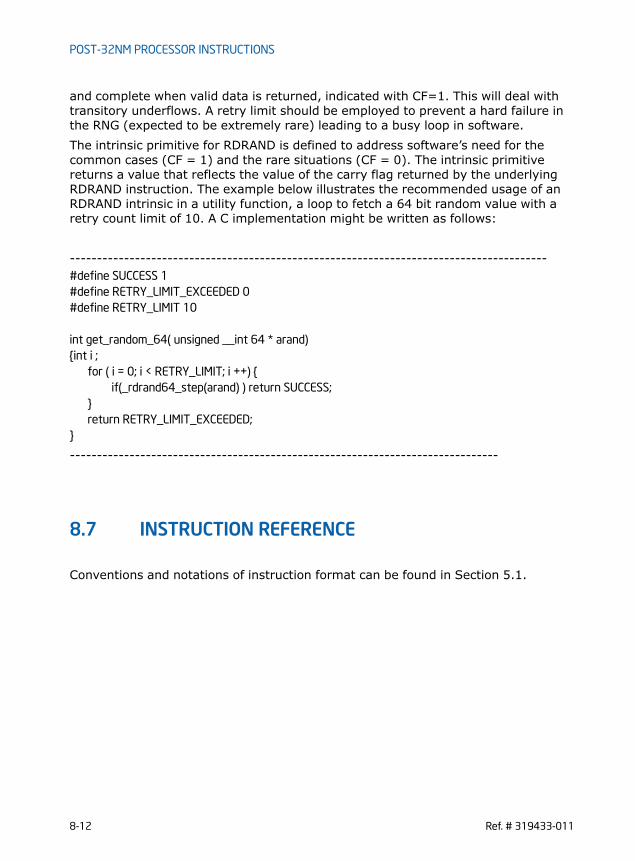
POST-32NM PROCESSOR INSTRUCTIONS
and complete when valid data is returned, indicated with CF=1. This will deal with transitory underflows. A retry limit should be employed to prevent a hard failure in the RNG (expected to be extremely rare) leading to a busy loop in software.The intrinsic primitive for RDRAND is defined to address software’s need for the common cases (CF = 1) and the rare situations (CF = 0). The intrinsic primitive returns a value that reflects the value of the carry flag returned by the underlying RDRAND instruction. The example below illustrates the recommended usage of an RDRAND intrinsic in a utility function, a loop to fetch a 64 bit random value with a retry count limit of 10. A C implementation might be written as follows:
----------------------------------------------------------------------------------------#define SUCCESS 1#define RETRY_LIMIT_EXCEEDED 0#define RETRY_LIMIT 10
int get_random_64( unsigned __int 64 * arand){int i ;
for ( i = 0; i < RETRY_LIMIT; i ++) {if(_rdrand64_step(arand) ) return SUCCESS;
}return RETRY_LIMIT_EXCEEDED;
}
-------------------------------------------------------------------------------
8.7 INSTRUCTION REFERENCE
Conventions and notations of instruction format can be found in Section 5.1.
8-12 Ref. # 319433-011

POST-32NM PROCESSOR INSTRUCTIONS
RDFSBASE/RDGSBASE—Read FS/GS Segment Base Register
Instruction Operand Encoding
Description
Loads the FS or GS segment base register into a general purpose register indicated by the modR/M:r/m field. The destination operand is a 32 or 64-bit general purpose register. The REX.W prefix indicates the operand size is 64 bit. If no REX.W prefix is used then the operand size is 32 bit and the upper 32 bits of the FS or GS base are ignored and bits [63:32] of the destination register will be written to 0. This instruction is supported only in 64-bit sub mode of the IA-32e mode.
Operation
If OperandSize = 64 then
DEST[63:0] ← FS/GS_Segment_Base_Register;
Else
DEST[31:0] ← FS/GS_Segment_Base_Register;
DEST[63:32] ←0;
Opcode/Instruction
Op/ En
64/32-bit Mode
CPUID Feature Flag
Description
F3 0F AE /0RDFSBASE r32
A V/I FSGSBASE Read FS base register and place the 32-bit result in the destina-tion register.
REX.W + F3 0F AE /0RDFSBASE r64
A V/I FSGSBASE Read FS base register and place the 64-bit result in the destina-tion register.
F3 0F AE /1RDGSBASE r32
A V/I FSGSBASE Read GS base register and place the 32-bit result in destination register.
REX.W + F3 0F AE /1RDGSBASE r64
A V/I FSGSBASE Read GS base register and place the 64-bit result in destination register.
Op/En Operand 1 Operand 2 Operand 3 Operand 4
A ModRM:r/m (w) NA NA NA
Ref. # 319433-011 8-13

POST-32NM PROCESSOR INSTRUCTIONS
Flags Affected
None
C/C++ Compiler Intrinsic Equivalent
RDFSBASE unsigned int _readfsbase_u32(void );
RDFSBASE unsigned __int64 _readfsbase_u64(void );
RDGSBASE unsigned int _readgsbase_u32(void );
RDGSBASE unsigned __int64 _readgsbase_u64(void );
Protected Mode Exceptions#UD Always
Real-Address Mode Exceptions#UD Always
Virtual-8086 Mode Exceptions#UD Always
Compatibility Mode Exceptions#UD Always
64-Bit Mode Exceptions#UD If the LOCK prefix is used.
If CR4.FSGSBASE[bit 16] = 0.If CPUID.07H.0H:EBX.FSGSBASE[bit 0] = 0.
8-14 Ref. # 319433-011

POST-32NM PROCESSOR INSTRUCTIONS
RDRAND—Read Random Number
Instruction Operand Encoding
Description
Loads a hardware generated random value and store it in the destination register. The size of the random value is determined by the destination register size and oper-ating mode. The Carry Flag indicates whether a random value is available at the time the instruction is executed. CF=1 indicates that the data in the destination is valid. Otherwise CF=0 and the data in the destination operand will be returned as zeros for the specified width. All other flags are forced to 0 in either situation. Soft-ware must check the state of CF=1 for determining if a valid random value has been returned, otherwise it is expected to loop and retry execution of RDRAND (see Section 8.6).This instruction is available at all privilege levels. For virtualization supporting lock-step operation, a virtualization control exists that allows the virtual machine monitor to trap on the instruction. "RDRAND exiting" will be controlled by bit 11 of the secondary processor-based VM-execution control. A VMEXIT due to RDRAND will have exit reason 57 (decimal).In 64-bit mode the instruction's default operation size is 32 bits. Using a REX prefix in the form of REX.B permits access to additional registers (R8-R15). Using a REX prefix in the form of REX.W promotes operation to 64 bit operands. See the summary chart at the beginning of this section for encoding data and limits.
Opcode/Instruction
Op/ En
64/32-bit Mode
CPUID Feature Flag
Description
0F C7 /6RDRAND r16
A V/V RDRAND Read a 16-bit random number and store in the destination reg-ister.
0F C7 /6RDRAND r32
A V/V RDRAND Read a 32-bit random number and store in the destination reg-ister.
REX.W + 0F C7 /6RDRAND r64
A V/I RDRAND Read a 64-bit random number and store in the destination reg-ister.
Op/En Operand 1 Operand 2 Operand 3 Operand 4
A ModRM:r/m (w) NA NA NA
Ref. # 319433-011 8-15

POST-32NM PROCESSOR INSTRUCTIONS
Operation
IF HW_RND_GEN.ready = 1
THEN
CASE of
osize is 64: DEST[63:0] ← HW_RND_GEN.data;
osize is 32: DEST[31:0] ← HW_RND_GEN.data;
osize is 16: DEST[15:0] ← HW_RND_GEN.data;
ESAC
CF ← 1;
ELSE
CASE of
osize is 64: DEST[63:0] ← 0;
osize is 32: DEST[31:0] ← 0;
osize is 16: DEST[15:0] ← 0;
ESAC
CF ← 0;
FI
OF, SF, ZF, AF, PF ← 0;
Flags Affected
All flags are affected.
C/C++ Compiler Intrinsic Equivalent
RDRAND int _rdrand16_step( unsigned short * );
RDRAND int _rdrand32_step( unsigned int * );
RDRAND int _rdrand64_step( unsigned __int64 *);
Protected Mode Exceptions#UD If the LOCK prefix is used.
8-16 Ref. # 319433-011

POST-32NM PROCESSOR INSTRUCTIONS
If the F2H or F3H prefix is used.If CPUID.01H:ECX.RDRAND[bit 30] = 0.
Real-Address Mode Exceptions#UD If the LOCK prefix is used.
If the F2H or F3H prefix is used.If CPUID.01H:ECX.RDRAND[bit 30] = 0.
Virtual-8086 Mode Exceptions#UD If the LOCK prefix is used.
If the F2H or F3H prefix is used.If CPUID.01H:ECX.RDRAND[bit 30] = 0.
Compatibility Mode Exceptions#UD If the LOCK prefix is used.
If the F2H or F3H prefix is used.If CPUID.01H:ECX.RDRAND[bit 30] = 0.
64-Bit Mode Exceptions#UD If the LOCK prefix is used.
If the F2H or F3H prefix is used.If CPUID.01H:ECX.RDRAND[bit 30] = 0.
Ref. # 319433-011 8-17

POST-32NM PROCESSOR INSTRUCTIONS
WRFSBASE/WRGSBASE—Write FS/GS Segment Base Register
Instruction Operand Encoding
Description
Loads the source operand into the FS or GS segment base register. The source operand is a 32 or 64-bit general purpose register. The REX.W prefix indicates the operand size is 64 bit. If no REX.W prefix is used then the operand size is 32 bit and the upper 32 bits of the FS or GS base register will be written to 0.This instruction is supported only in 64-bit sub mode of the IA-32e mode.
Operation
If osize = 64 then
FS/GS_Segment_Base_Register ← SRC[63:0];
Else
FS/GS_Segment_Base_Register[63:32] ← 0;
FS/GS_Segment_Base_Register[31:0] ← SRC[31:0];
Opcode/Instruction
Op/ En
64/32-bit Mode
CPUID Feature Flag
Description
F3 0F AE /2WRFSBASE r32
A V/I FSGSBASE Write the 32-bit value in the source register to FS base regis-ter.
REX.W + F3 0F AE /2WRFSBASE r64
A V/I FSGSBASE Write the 64-bit value in the source register to FS base regis-ter.
F3 0F AE /3WRGSBASE r32
A V/I FSGSBASE Write the 32-bit value in the source register to GS base regis-ter.
REX.W + F3 0F AE /3WRGSBASE r64
A V/I FSGSBASE Write the 64-bit value in the source register to GS base regis-ter.
Op/En Operand 1 Operand 2 Operand 3 Operand 4
A ModRM:r/m (r) NA NA NA
8-18 Ref. # 319433-011

POST-32NM PROCESSOR INSTRUCTIONS
Flags Affected
None
C/C++ Compiler Intrinsic Equivalent
WRFSBASE void _writefsbase_u32( unsigned int );
WRFSBASE _writefsbase_u64( unsigned __int64 );
WRGSBASE void _writegsbase_u32( unsigned int );
WRGSBASE _writegsbase_u64( unsigned __int64 );
Protected Mode Exceptions#UD Always
Real-Address Mode Exceptions#UD Always
Virtual-8086 Mode Exceptions#UD Always
Compatibility Mode Exceptions#UD Always
64-Bit Mode Exceptions#UD If the LOCK prefix is used.
If CR4.FSGSBASE[bit 16] = 0.If CPUID.07H.0H:EBX.FSGSBASE[bit 0] = 0
#GP(0) If the SRC contains a non-canonical address.
Ref. # 319433-011 8-19

POST-32NM PROCESSOR INSTRUCTIONS
VCVTPH2PS – Convert 16-bit FP values to Single-Precision FP values
Instruction Operand Encoding
Description
Converts four/eight packed half precision (16-bits) floating-point values in the low-order 64/128 bits of an XMM/YMM register or 64/128-bit memory location to four/eight packed single-precision floating-point values and writes the converted values into the destination XMM/YMM register.If case of a denormal operand, the correct normal result is returned. MXCSR.DAZ is ignored and is treated as if it 0. No denormal exception is reported on MXCSR.128-bit version: The source operand is a XMM register or 64-bit memory location. The destination operand is a XMM register. The upper bits (255:128) of the corre-sponding destination YMM register are zeroed.256-bit version: The source operand is a XMM register or 128-bit memory location. The destination operand is a YMM register. The diagram below illustrates how data is converted from four packed half precision (in 64 bits) to four single precision (in 128 bits) FP values.Note: VEX.vvvv is reserved (must be 1111b).
Opcode/Instruction
Op/ En
64/32-bit Mode
CPUID Feature Flag
Description
VEX.256.66.0F38.W0 13 /r A V/V F16C Convert eight packed half precision (16-bit) floating-point values in xmm2/m128 to packed single-precision floating-point value in ymm1.
VCVTPH2PS ymm1, xmm2/m128
VEX.128.66.0F38.W0 13 /r A V/V F16C Convert four packed half precision (16-bit) floating-point values in xmm2/m64 to packed single-precision floating-point value in xmm1.
VCVTPH2PS xmm1, xmm2/m64
Op/En Operand 1 Operand 2 Operand 3 Operand 4
A ModRM:reg (w) ModRM:r/m (r) NA NA
8-20 Ref. # 319433-011

POST-32NM PROCESSOR INSTRUCTIONS
Figure 8-3. VCVTPH2PS (128-bit Version)
OperationvCvt_h2s(SRC1[15:0]){RETURN Cvt_Half_Precision_To_Single_Precision(SRC1[15:0]);}
VCVTPH2PS (VEX.256 encoded version)DEST[31:0] vCvt_h2s(SRC1[15:0]);DEST[63:32] vCvt_h2s(SRC1[31:16]);DEST[95:64] vCvt_h2s(SRC1[47:32]);DEST[127:96] vCvt_h2s(SRC1[63:48]);DEST[159:128] vCvt_h2s(SRC1[79:64]);DEST[191:160] vCvt_h2s(SRC1[95:80]);DEST[223:192] vCvt_h2s(SRC1[111:96]);
DEST[255:224] vCvt_h2s(SRC1[127:112]);
VCVTPH2PS (VEX.128 encoded version) DEST[31:0] vCvt_h2s(SRC1[15:0]);DEST[63:32] vCvt_h2s(SRC1[31:16]);DEST[95:64] vCvt_h2s(SRC1[47:32]);DEST[127:96] vCvt_h2s(SRC1[63:48]);DEST[VLMAX-1:128] 0
Flags Affected
None
VH0VH1VH2VH3
15 031 1647 3263 4895 64127 96
VS0VS1VS2VS3
31 063 3295 64127 96
convert convert
convertconvert
xmm2/mem64
xmm1
VCVTPH2PS xmm1, xmm2/mem64, imm8
Ref. # 319433-011 8-21

POST-32NM PROCESSOR INSTRUCTIONS
Intel C/C++ Compiler Intrinsic Equivalent
__m128 _mm_cvtph_ps ( __m128i m1);
__m256 _mm256_cvtph_ps ( __m128i m1)
SIMD Floating-Point ExceptionsInvalid
Other ExceptionsExceptions Type 11 (do not report #AC); additionally#UD If VEX.W=1.
8-22 Ref. # 319433-011
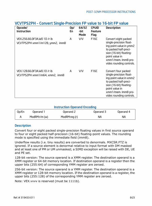
POST-32NM PROCESSOR INSTRUCTIONS
VCVTPS2PH – Convert Single-Precision FP value to 16-bit FP value
Instruction Operand Encoding
Description
Convert four or eight packed single-precision floating values in first source operand to four or eight packed half-precision (16-bit) floating-point values. The rounding mode is specified using the immediate field (imm8).Underflow results (i.e. tiny results) are converted to denormals. MXCSR.FTZ is ignored. If a source element is denormal relative to input format with DM masked and at least one of PM or UM unmasked; a SIMD exception will be raised with DE, UE and PE set.128-bit version: The source operand is a XMM register. The destination operand is a XMM register or 64-bit memory location. If destination operand is a register then the upper bits (255:64) of corresponding YMM register are zeroed.256-bit version: The source operand is a YMM register. The destination operand is a XMM register or 128-bit memory location. If the destination operand is a register, the upper bits (255:128) of the corresponding YMM register are zeroed.Note: VEX.vvvv is reserved (must be 1111b).
Opcode/Instruction
Op/ En
64/32-bit Mode
CPUID Feature Flag
Description
VEX.256.66.0F3A.W0 1D /r ib A V/V F16C Convert eight packed single-precision float-ing-point value in ymm2 to packed half-preci-sion (16-bit) floating-point value in xmm1/mem. Imm8 pro-vides rounding controls.
VCVTPS2PH xmm1/m128, ymm2, imm8
VEX.128.66.0F3A.W0.1D /r ib A V/V F16C Convert four packed single-precision float-ing-point value in xmm2 to packed half-preci-sion (16-bit) floating-point value in xmm1/mem. Imm8 pro-vides rounding controls.
VCVTPS2PH xmm1/m64, xmm2, imm8
Op/En Operand 1 Operand 2 Operand 3 Operand 4
A ModRM:r/m (w) ModRM:reg (r) NA NA
Ref. # 319433-011 8-23

POST-32NM PROCESSOR INSTRUCTIONS
The diagram below illustrates how data is converted from four packed single preci-sion (in 128 bits) to four half precision (in 64 bits) FP values.
Figure 8-4. VCVTPS2PH (128-bit Version)
The immediate byte defines several bit fields that controls rounding operation. Theeffect and encoding of RC field are listed in Table 8-12.
OperationvCvt_s2h(SRC1[31:0]){IF Imm[2] = 0THEN // using Imm[1:0] for rounding control, see Table 8-12
RETURN Cvt_Single_Precision_To_Half_Precision_FP_Imm(SRC1[31:0]);ELSE // using MXCSR.RC for rounding control
RETURN Cvt_Single_Precision_To_Half_Precision_FP_Mxcsr(SRC1[31:0]);FI;
Table 8-12. Immediate Byte Encoding for 16-bit Floating-Point Conversion Instructions
Bits Field Name/value Description Comment
Imm[1:0] RC=00B Round to nearest even If Imm[2] = 0
RC=01B Round down
RC=10B Round up
RC=11B Truncate
Imm[2] MS1=0 Use imm[1:0] for round-ing
Ignore MXCSR.RC
MS1=1 Use MXCSR.RC for round-ing
Imm[7:3] Ignored Ignored by processor
VH0VH1VH2VH3
15 031 1647 3263 4895 64127 96
VS0VS1VS2VS3
31 063 3295 64127 96
xmm1/mem64
xmm2
VCVTPS2PH xmm1/mem64, xmm2, imm8
convertconvert convertconvert
8-24 Ref. # 319433-011

POST-32NM PROCESSOR INSTRUCTIONS
}
VCVTPS2PH (VEX.256 encoded version)DEST[15:0] vCvt_s2h(SRC1[31:0]);DEST[31:16] vCvt_s2h(SRC1[63:32]);DEST[47:32] vCvt_s2h(SRC1[95:64]);DEST[63:48] vCvt_s2h(SRC1[127:96]);DEST[79:64] vCvt_s2h(SRC1[159:128]);DEST[95:80] vCvt_s2h(SRC1[191:160]);DEST[111:96] vCvt_s2h(SRC1[223:192]);DEST[127:112] vCvt_s2h(SRC1[255:224]);DEST[255:128] 0
VCVTPS2PH (VEX.128 encoded version) DEST[15:0] vCvt_s2h(SRC1[31:0]);DEST[31:16] vCvt_s2h(SRC1[63:32]);DEST[47:32] vCvt_s2h(SRC1[95:64]);DEST[63:48] vCvt_s2h(SRC1[127:96]);DEST[VLMAX-1:64] 0
Flags Affected
None
Intel C/C++ Compiler Intrinsic Equivalent
__m128i _mm_cvtps_ph ( __m128 m1, const int imm);
__m128i _mm256_cvtps_ph(__m256 m1, const int imm);
SIMD Floating-Point ExceptionsInvalid, Underflow, Overflow, Precision, Denormal (if MXCSR.DAZ=0);
Other ExceptionsExceptions Type 11 (do not report #AC); additionally#UD If VEX.W=1.
Ref. # 319433-011 8-25

POST-32NM PROCESSOR INSTRUCTIONS
This page was
intentionally left
blank.
8-26 Ref. # 319433-011

INSTRUCTION SUMMARY
APPENDIX AINSTRUCTION SUMMARY
A.1 AVX INSTRUCTIONSIn AVX, most SSE/SSE2/SSE3/SSSE3/SSE4 Instructions have been promoted to support VEX.128 encodings which, for non-memory-store versions implies support for zeroing upper bits of YMM registers. Table A-1 summarizes the promotion status for existing instructions. The column “VEX.256” indicates whether 256-bit vector form of the instruction using the VEX.256 prefix encoding is supported. The column “VEX.128” indicates whether the instruction using VEX.128 prefix encoding is supported.
Table A-1. Promoted SSE/SSE2/SSE3/SSSE3/SSE4 Instructions in AVX
VEX.256 Encoding
VEX.128 Encoding
Group Instruction If No, Reason?
yes yes YY 0F 1X MOVUPS
no yes MOVSS scalar
yes yes MOVUPD
no yes MOVSD scalar
no yes MOVLPS Note 1
no yes MOVLPD Note 1
no yes MOVLHPS Redundant with VPERMILPS
yes yes MOVDDUP
yes yes MOVSLDUP
yes yes UNPCKLPS
yes yes UNPCKLPD
yes yes UNPCKHPS
yes yes UNPCKHPD
no yes MOVHPS Note 1
no yes MOVHPD Note 1
no yes MOVHLPS Redundant with VPERMILPS
yes yes MOVAPS
yes yes MOVSHDUP
yes yes MOVAPD
Ref. # 319433-011 A-1

INSTRUCTION SUMMARY
no no CVTPI2PS MMX
no yes CVTSI2SS scalar
no no CVTPI2PD MMX
no yes CVTSI2SD scalar
yes yes MOVNTPS
yes yes MOVNTPD
no no CVTTPS2PI MMX
no yes CVTTSS2SI scalar
no no CVTTPD2PI MMX
no yes CVTTSD2SI scalar
no no CVTPS2PI MMX
no yes CVTSS2SI scalar
no no CVTPD2PI MMX
no yes CVTSD2SI scalar
no yes UCOMISS scalar
no yes UCOMISD scalar
no yes COMISS scalar
no yes COMISD scalar
yes yes YY 0F 5X MOVMSKPS
yes yes MOVMSKPD
yes yes SQRTPS
no yes SQRTSS scalar
yes yes SQRTPD
no yes SQRTSD scalar
yes yes RSQRTPS
no yes RSQRTSS scalar
yes yes RCPPS
no yes RCPSS scalar
yes yes ANDPS
yes yes ANDPD
Table A-1. Promoted SSE/SSE2/SSE3/SSSE3/SSE4 Instructions in AVX
VEX.256 Encoding
VEX.128 Encoding
Group Instruction If No, Reason?
A-2 Ref. # 319433-011

INSTRUCTION SUMMARY
yes yes ANDNPS
yes yes ANDNPD
yes yes ORPS
yes yes ORPD
yes yes XORPS
yes yes XORPD
yes yes ADDPS
no yes ADDSS scalar
yes yes ADDPD
no yes ADDSD scalar
yes yes MULPS
no yes MULSS scalar
yes yes MULPD
no yes MULSD scalar
yes yes CVTPS2PD
no yes CVTSS2SD scalar
yes yes CVTPD2PS
no yes CVTSD2SS scalar
yes yes CVTDQ2PS
yes yes CVTPS2DQ
yes yes CVTTPS2DQ
yes yes SUBPS
no yes SUBSS scalar
yes yes SUBPD
no yes SUBSD scalar
yes yes MINPS
no yes MINSS scalar
yes yes MINPD
no yes MINSD scalar
yes yes DIVPS
Table A-1. Promoted SSE/SSE2/SSE3/SSSE3/SSE4 Instructions in AVX
VEX.256 Encoding
VEX.128 Encoding
Group Instruction If No, Reason?
Ref. # 319433-011 A-3

INSTRUCTION SUMMARY
no yes DIVSS scalar
yes yes DIVPD
no yes DIVSD scalar
yes yes MAXPS
no yes MAXSS scalar
yes yes MAXPD
no yes MAXSD scalar
no yes YY 0F 6X PUNPCKLBW VI
no yes PUNPCKLWD VI
no yes PUNPCKLDQ VI
no yes PACKSSWB VI
no yes PCMPGTB VI
no yes PCMPGTW VI
no yes PCMPGTD VI
no yes PACKUSWB VI
no yes PUNPCKHBW VI
no yes PUNPCKHWD VI
no yes PUNPCKHDQ VI
no yes PACKSSDW VI
no yes PUNPCKLQDQ VI
no yes PUNPCKHQDQ VI
no yes MOVD scalar
no yes MOVQ scalar
yes yes MOVDQA
yes yes MOVDQU
no yes YY 0F 7X PSHUFD VI
no yes PSHUFHW VI
no yes PSHUFLW VI
no yes PCMPEQB VI
no yes PCMPEQW VI
Table A-1. Promoted SSE/SSE2/SSE3/SSSE3/SSE4 Instructions in AVX
VEX.256 Encoding
VEX.128 Encoding
Group Instruction If No, Reason?
A-4 Ref. # 319433-011

INSTRUCTION SUMMARY
no yes PCMPEQD VI
yes yes HADDPD
yes yes HADDPS
yes yes HSUBPD
yes yes HSUBPS
no yes MOVD VI
no yes MOVQ VI
yes yes MOVDQA
yes yes MOVDQU
no yes YY 0F AX LDMXCSR
no yes STMXCSR
yes yes YY 0F CX CMPPS
no yes CMPSS scalar
yes yes CMPPD
no yes CMPSD scalar
no yes PINSRW VI
no yes PEXTRW VI
yes yes SHUFPS
yes yes SHUFPD
yes yes YY 0F DX ADDSUBPD
yes yes ADDSUBPS
no yes PSRLW VI
no yes PSRLD VI
no yes PSRLQ VI
no yes PADDQ VI
no yes PMULLW VI
no no MOVQ2DQ MMX
no no MOVDQ2Q MMX
no yes PMOVMSKB VI
no yes PSUBUSB VI
Table A-1. Promoted SSE/SSE2/SSE3/SSSE3/SSE4 Instructions in AVX
VEX.256 Encoding
VEX.128 Encoding
Group Instruction If No, Reason?
Ref. # 319433-011 A-5

INSTRUCTION SUMMARY
no yes PSUBUSW VI
no yes PMINUB VI
no yes PAND VI
no yes PADDUSB VI
no yes PADDUSW VI
no yes PMAXUB VI
no yes PANDN VI
no yes YY 0F EX PAVGB VI
no yes PSRAW VI
no yes PSRAD VI
no yes PAVGW VI
no yes PMULHUW VI
no yes PMULHW VI
yes yes CVTPD2DQ
yes yes CVTTPD2DQ
yes yes CVTDQ2PD
yes yes MOVNTDQ VI
no yes PSUBSB VI
no yes PSUBSW VI
no yes PMINSW VI
no yes POR VI
no yes PADDSB VI
no yes PADDSW VI
no yes PMAXSW VI
no yes PXOR VI
yes yes YY 0F FX LDDQU VI
no yes PSLLW VI
no yes PSLLD VI
no yes PSLLQ VI
no yes PMULUDQ VI
Table A-1. Promoted SSE/SSE2/SSE3/SSSE3/SSE4 Instructions in AVX
VEX.256 Encoding
VEX.128 Encoding
Group Instruction If No, Reason?
A-6 Ref. # 319433-011

INSTRUCTION SUMMARY
no yes PMADDWD VI
no yes PSADBW VI
no yes MASKMOVDQU
no yes PSUBB VI
no yes PSUBW VI
no yes PSUBD VI
no yes PSUBQ VI
no yes PADDB VI
no yes PADDW VI
no yes PADDD VI
no yes SSSE3 PHADDW VI
no yes PHADDSW VI
no yes PHADDD VI
no yes PHSUBW VI
no yes PHSUBSW VI
no yes PHSUBD VI
no yes PMADDUBSW VI
no yes PALIGNR VI
no yes PSHUFB VI
no yes PMULHRSW VI
no yes PSIGNB VI
no yes PSIGNW VI
no yes PSIGND VI
no yes PABSB VI
no yes PABSW VI
no yes PABSD VI
yes yes SSE4.1 BLENDPS
yes yes BLENDPD
yes yes BLENDVPS Note 2
yes yes BLENDVPD Note 2
Table A-1. Promoted SSE/SSE2/SSE3/SSSE3/SSE4 Instructions in AVX
VEX.256 Encoding
VEX.128 Encoding
Group Instruction If No, Reason?
Ref. # 319433-011 A-7

INSTRUCTION SUMMARY
no yes DPPD
yes yes DPPS
no yes EXTRACTPS Note 3
no yes INSERTPS Note 3
no yes MOVNTDQA
no yes MPSADBW VI
no yes PACKUSDW VI
no yes PBLENDVB VI
no yes PBLENDW VI
no yes PCMPEQQ VI
no yes PEXTRD VI
no yes PEXTRQ VI
no yes PEXTRB VI
no yes PEXTRW VI
no yes PHMINPOSUW VI
no yes PINSRB VI
no yes PINSRD VI
no yes PINSRQ VI
no yes PMAXSB VI
no yes PMAXSD VI
no yes PMAXUD VI
no yes PMAXUW VI
no yes PMINSB VI
no yes PMINSD VI
no yes PMINUD VI
no yes PMINUW VI
no yes PMOVSXxx VI
no yes PMOVZXxx VI
no yes PMULDQ VI
no yes PMULLD VI
Table A-1. Promoted SSE/SSE2/SSE3/SSSE3/SSE4 Instructions in AVX
VEX.256 Encoding
VEX.128 Encoding
Group Instruction If No, Reason?
A-8 Ref. # 319433-011

INSTRUCTION SUMMARY
Description of Column “If No, Reason?”MMX: Instructions referencing MMX registers do not support VEX.Scalar: Scalar instructions are not promoted to 256-bit.integer: Integer instructions are not promoted.VI: “Vector Integer” instructions are not promoted to 256-bit.Note 1: MOVLPD/PS and MOVHPD/PS are not promoted to 256-bit. The equivalent functionality are provided by VINSERTF128 and VEXTRACTF128 instructions as the existing instructions have no natural 256b extension.Note 2: BLENDVPD and BLENDVPS are superseded by the more flexible VBLENDVPD and VBLENDVPS.Note 3: It is expected that using 128-bit INSERTPS followed by a VINSERTF128 would be better than promoting INSERTPS to 256-bit (for example).
yes yes PTEST
yes yes ROUNDPD
yes yes ROUNDPS
no yes ROUNDSD scalar
no yes ROUNDSS scalar
no yes SSE4.2 PCMPGTQ VI
no no SSE4.2 CRC32c integer
no yes PCMPESTRI VI
no yes PCMPESTRM VI
no yes PCMPISTRI VI
no yes PCMPISTRM VI
no no POPCNT POPCNT integer
no yes AESNI AESDEC VI
no yes AESDECLAST VI
no yes AESENC VI
no yes AESECNLAST VI
no yes AESIMC VI
no yes AESKEYGENASSIST VI
no yes CLMUL PCLMULQDQ VI
Table A-1. Promoted SSE/SSE2/SSE3/SSSE3/SSE4 Instructions in AVX
VEX.256 Encoding
VEX.128 Encoding
Group Instruction If No, Reason?
Ref. # 319433-011 A-9

INSTRUCTION SUMMARY
A.2 PROMOTED VECTOR INTEGER INSTRUCTIONS IN AVX2
In AVX2, most SSE/SSE2/SSE3/SSSE3/SSE4 vector integer instructions have been promoted to support VEX.256 encodings. Table A-2 summarizes the promotion status for existing instructions. The column “VEX.128” indicates whether the instruc-tion using VEX.128 prefix encoding is supported. The column “VEX.256” indicates whether 256-bit vector form of the instruction using the VEX.256 prefix encoding is supported, and under which feature flag.
Table A-2. Promoted Vector Integer SIMD Instructions in AVX2
VEX.256 Encoding
VEX.128 Encoding
Group Instruction
AVX2 AVX YY 0F 6X PUNPCKLBW
AVX2 AVX PUNPCKLWD
AVX2 AVX PUNPCKLDQ
AVX2 AVX PACKSSWB
AVX2 AVX PCMPGTB
AVX2 AVX PCMPGTW
AVX2 AVX PCMPGTD
AVX2 AVX PACKUSWB
AVX2 AVX PUNPCKHBW
AVX2 AVX PUNPCKHWD
AVX2 AVX PUNPCKHDQ
AVX2 AVX PACKSSDW
AVX2 AVX PUNPCKLQDQ
AVX2 AVX PUNPCKHQDQ
no AVX MOVD
no AVX MOVQ
AVX AVX MOVDQA
AVX AVX MOVDQU
AVX2 AVX YY 0F 7X PSHUFD
AVX2 AVX PSHUFHW
AVX2 AVX PSHUFLW
AVX2 AVX PCMPEQB
A-10 Ref. # 319433-011
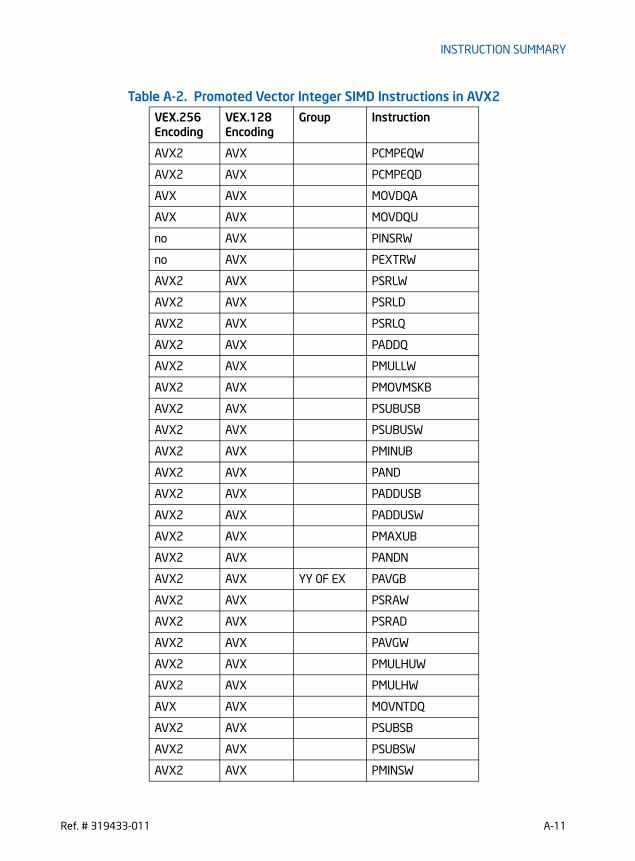
INSTRUCTION SUMMARY
AVX2 AVX PCMPEQW
AVX2 AVX PCMPEQD
AVX AVX MOVDQA
AVX AVX MOVDQU
no AVX PINSRW
no AVX PEXTRW
AVX2 AVX PSRLW
AVX2 AVX PSRLD
AVX2 AVX PSRLQ
AVX2 AVX PADDQ
AVX2 AVX PMULLW
AVX2 AVX PMOVMSKB
AVX2 AVX PSUBUSB
AVX2 AVX PSUBUSW
AVX2 AVX PMINUB
AVX2 AVX PAND
AVX2 AVX PADDUSB
AVX2 AVX PADDUSW
AVX2 AVX PMAXUB
AVX2 AVX PANDN
AVX2 AVX YY 0F EX PAVGB
AVX2 AVX PSRAW
AVX2 AVX PSRAD
AVX2 AVX PAVGW
AVX2 AVX PMULHUW
AVX2 AVX PMULHW
AVX AVX MOVNTDQ
AVX2 AVX PSUBSB
AVX2 AVX PSUBSW
AVX2 AVX PMINSW
Table A-2. Promoted Vector Integer SIMD Instructions in AVX2
VEX.256 Encoding
VEX.128 Encoding
Group Instruction
Ref. # 319433-011 A-11

INSTRUCTION SUMMARY
AVX2 AVX POR
AVX2 AVX PADDSB
AVX2 AVX PADDSW
AVX2 AVX PMAXSW
AVX2 AVX PXOR
AVX AVX YY 0F FX LDDQU
AVX2 AVX PSLLW
AVX2 AVX PSLLD
AVX2 AVX PSLLQ
AVX2 AVX PMULUDQ
AVX2 AVX PMADDWD
AVX2 AVX PSADBW
AVX2 AVX MASKMOVDQU
AVX2 AVX PSUBB
AVX2 AVX PSUBW
AVX2 AVX PSUBD
AVX2 AVX PSUBQ
AVX2 AVX PADDB
AVX2 AVX PADDW
AVX2 AVX PADDD
AVX2 AVX SSSE3 PHADDW
AVX2 AVX PHADDSW
AVX2 AVX PHADDD
AVX2 AVX PHSUBW
AVX2 AVX PHSUBSW
AVX2 AVX PHSUBD
AVX2 AVX PMADDUBSW
AVX2 AVX PALIGNR
AVX2 AVX PSHUFB
AVX2 AVX PMULHRSW
Table A-2. Promoted Vector Integer SIMD Instructions in AVX2
VEX.256 Encoding
VEX.128 Encoding
Group Instruction
A-12 Ref. # 319433-011

INSTRUCTION SUMMARY
AVX2 AVX PSIGNB
AVX2 AVX PSIGNW
AVX2 AVX PSIGND
AVX2 AVX PABSB
AVX2 AVX PABSW
AVX2 AVX PABSD
AVX2 AVX MOVNTDQA
AVX2 AVX MPSADBW
AVX2 AVX PACKUSDW
AVX2 AVX PBLENDVB
AVX2 AVX PBLENDW
AVX2 AVX PCMPEQQ
no AVX PEXTRD
no AVX PEXTRQ
no AVX PEXTRB
no AVX PEXTRW
no AVX PHMINPOSUW
no AVX PINSRB
no AVX PINSRD
no AVX PINSRQ
AVX2 AVX PMAXSB
AVX2 AVX PMAXSD
AVX2 AVX PMAXUD
AVX2 AVX PMAXUW
AVX2 AVX PMINSB
AVX2 AVX PMINSD
AVX2 AVX PMINUD
AVX2 AVX PMINUW
AVX2 AVX PMOVSXxx
AVX2 AVX PMOVZXxx
Table A-2. Promoted Vector Integer SIMD Instructions in AVX2
VEX.256 Encoding
VEX.128 Encoding
Group Instruction
Ref. # 319433-011 A-13

INSTRUCTION SUMMARY
Table A-3 compares complementary SIMD functionalities introduced in AVX and AVX2. instructions.
AVX2 AVX PMULDQ
AVX2 AVX PMULLD
AVX AVX PTEST
AVX2 AVX SSE4.2 PCMPGTQ
no AVX PCMPESTRI
no AVX PCMPESTRM
no AVX PCMPISTRI
no AVX PCMPISTRM
no AVX AESNI AESDEC
no AVX AESDECLAST
no AVX AESENC
no AVX AESECNLAST
no AVX AESIMC
no AVX AESKEYGENASSIST
no AVX CLMUL PCLMULQDQ
Table A-3. VEX-Only SIMD Instructions in AVX and AVX2
AVX2 AVX Comment
VBROADCASTI128 VBROADCASTF128 256-bit only
VBROADCASTSD ymm1, xmm VBROADCASTSD ymm1, m64 256-bit only
VBROADCASTSS (from xmm) VBROADCASTSS (from m32)
VEXTRACTI128 VEXTRACTF128 256-bit only
VINSERTI128 VINSERTF128 256-bit only
VPMASKMOVD VMASKMOVPS
VPMASKMOVQ! VMASKMOVPD
VPERMILPD in-lane
VPERMILPS in-lane
VPERM2I128 VPERM2F128 256-bit only
Table A-2. Promoted Vector Integer SIMD Instructions in AVX2
VEX.256 Encoding
VEX.128 Encoding
Group Instruction
A-14 Ref. # 319433-011
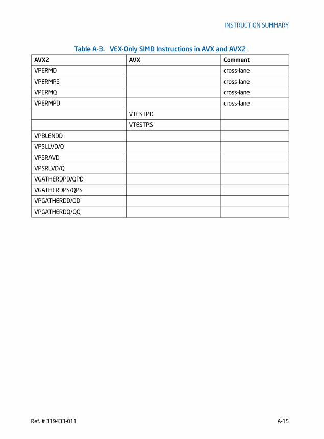
INSTRUCTION SUMMARY
VPERMD cross-lane
VPERMPS cross-lane
VPERMQ cross-lane
VPERMPD cross-lane
VTESTPD
VTESTPS
VPBLENDD
VPSLLVD/Q
VPSRAVD
VPSRLVD/Q
VGATHERDPD/QPD
VGATHERDPS/QPS
VPGATHERDD/QD
VPGATHERDQ/QQ
Table A-3. VEX-Only SIMD Instructions in AVX and AVX2
AVX2 AVX Comment
Ref. # 319433-011 A-15

INSTRUCTION SUMMARY
Table A-4. New Primitive in AVX2 Instructions Opcode Instruction Description
VEX.NDS.256.66.0F38.W0 36 /r
VPERMD ymm1, ymm2, ymm3/m256
Permute doublewords in ymm3/m256 using indexes in ymm2 and store the result in ymm1.
VEX.NDS.256.66.0F38.W0 01 /r
VPERMPD ymm1, ymm2, ymm3/m256
Permute double-precision FP elements in ymm3/m256 using indexes in ymm2 and store the result in ymm1.
VEX.NDS.256.66.0F38.W0 16 /r
VPERMPS ymm1, ymm2, ymm3/m256
Permute single-precision FP elements in ymm3/m256 using indexes in ymm2 and store the result in ymm1.
VEX.NDS.256.66.0F38.W0 00 /r
VPERMQ ymm1, ymm2, ymm3/m256
Permute quadwords in ymm3/m256 using indexes in ymm2 and store the result in ymm1.
VEX.NDS.128.66.0F38.W0 47 /r
VPSLLVD xmm1, xmm2, xmm3/m128
Shift doublewords in xmm2 left by amount specified in the corresponding element of xmm3/m128 while shifting in 0s.
VEX.NDS.128.66.0F38.W1 47 /r
VPSLLVQ xmm1, xmm2, xmm3/m128
Shift quadwords in xmm2 left by amount specified in the corresponding element of xmm3/m128 while shifting in 0s.
VEX.NDS.256.66.0F38.W0 47 /r
VPSLLVD ymm1, ymm2, ymm3/m256
Shift doublewords in ymm2 left by amount specified in the corresponding element of ymm3/m256 while shifting in 0s.
VEX.NDS.256.66.0F38.W1 47 /r
VPSLLVQ ymm1, ymm2, ymm3/m256
Shift quadwords in ymm2 left by amount specified in the corresponding element of ymm3/m256 while shifting in 0s.
VEX.NDS.128.66.0F38.W0 46 /r
VPSRAVD xmm1, xmm2, xmm3/m128
Shift doublewords in xmm2 right by amount specified in the corresponding element of xmm3/m128 while shifting in the sign bits.
VEX.NDS.128.66.0F38.W0 45 /r
VPSRLVD xmm1, xmm2, xmm3/m128
Shift doublewords in xmm2 right by amount specified in the corresponding element of xmm3/m128 while shifting in 0s.
VEX.NDS.128.66.0F38.W1 45 r
VPSRLVQ xmm1, xmm2, xmm3/m128
Shift quadwords in xmm2 right by amount specified in the corresponding element of xmm3/m128 while shifting in 0s.
VEX.NDS.256.66.0F38.W0 45 /r
VPSRLVD ymm1, ymm2, ymm3/m256
Shift doublewords in ymm2 right by amount specified in the corresponding element of ymm3/m256 while shifting in 0s.
A-16 Ref. # 319433-011
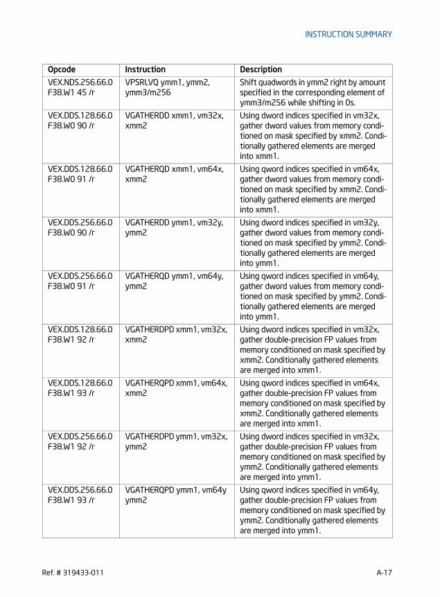
INSTRUCTION SUMMARY
VEX.NDS.256.66.0F38.W1 45 /r
VPSRLVQ ymm1, ymm2, ymm3/m256
Shift quadwords in ymm2 right by amount specified in the corresponding element of ymm3/m256 while shifting in 0s.
VEX.DDS.128.66.0F38.W0 90 /r
VGATHERDD xmm1, vm32x, xmm2
Using dword indices specified in vm32x, gather dword values from memory condi-tioned on mask specified by xmm2. Condi-tionally gathered elements are merged into xmm1.
VEX.DDS.128.66.0F38.W0 91 /r
VGATHERQD xmm1, vm64x, xmm2
Using qword indices specified in vm64x, gather dword values from memory condi-tioned on mask specified by xmm2. Condi-tionally gathered elements are merged into xmm1.
VEX.DDS.256.66.0F38.W0 90 /r
VGATHERDD ymm1, vm32y, ymm2
Using dword indices specified in vm32y, gather dword values from memory condi-tioned on mask specified by ymm2. Condi-tionally gathered elements are merged into ymm1.
VEX.DDS.256.66.0F38.W0 91 /r
VGATHERQD ymm1, vm64y, ymm2
Using qword indices specified in vm64y, gather dword values from memory condi-tioned on mask specified by ymm2. Condi-tionally gathered elements are merged into ymm1.
VEX.DDS.128.66.0F38.W1 92 /r
VGATHERDPD xmm1, vm32x, xmm2
Using dword indices specified in vm32x, gather double-precision FP values from memory conditioned on mask specified by xmm2. Conditionally gathered elements are merged into xmm1.
VEX.DDS.128.66.0F38.W1 93 /r
VGATHERQPD xmm1, vm64x, xmm2
Using qword indices specified in vm64x, gather double-precision FP values from memory conditioned on mask specified by xmm2. Conditionally gathered elements are merged into xmm1.
VEX.DDS.256.66.0F38.W1 92 /r
VGATHERDPD ymm1, vm32x, ymm2
Using dword indices specified in vm32x, gather double-precision FP values from memory conditioned on mask specified by ymm2. Conditionally gathered elements are merged into ymm1.
VEX.DDS.256.66.0F38.W1 93 /r
VGATHERQPD ymm1, vm64y ymm2
Using qword indices specified in vm64y, gather double-precision FP values from memory conditioned on mask specified by ymm2. Conditionally gathered elements are merged into ymm1.
Opcode Instruction Description
Ref. # 319433-011 A-17

INSTRUCTION SUMMARY
VEX.DDS.128.66.0F38.W0 92 /r
VGATHERDPS xmm1, vm32x, xmm2
Using dword indices specified in vm32x, gather single-precision FP values from memory conditioned on mask specified by xmm2. Conditionally gathered elements are merged into xmm1.
VEX.DDS.128.66.0F38.W0 93 /r
VGATHERQPS xmm1, vm64x, xmm2
Using qword indices specified in vm64x, gather single-precision FP values from memory conditioned on mask specified by xmm2. Conditionally gathered elements are merged into xmm1.
VEX.DDS.256.66.0F38.W0 92 /r
VGATHERDPS ymm1, vm32y, ymm2
Using dword indices specified in vm32y, gather single-precision FP values from memory conditioned on mask specified by ymm2. Conditionally gathered elements are merged into ymm1.
VEX.DDS.256.66.0F38.W0 93 /r
VGATHERQPS ymm1, vm64y, ymm2
Using qword indices specified in vm64y, gather single-precision FP values from memory conditioned on mask specified by ymm2. Conditionally gathered elements are merged into ymm1.
VEX.DDS.128.66.0F38.W1 90 /r
VGATHERDQ xmm1, vm32x, xmm2
Using dword indices specified in vm32x, gather qword values from memory condi-tioned on mask specified by xmm2. Condi-tionally gathered elements are merged into xmm1.
VEX.DDS.128.66.0F38.W1 91 /r
VGATHERQQ xmm1, vm64x, xmm2
Using qword indices specified in vm64x, gather qword values from memory condi-tioned on mask specified by xmm2. Condi-tionally gathered elements are merged into xmm1.
VEX.DDS.256.66.0F38.W1 90 /r
VGATHERDQ ymm1, vm32x, ymm2
Using dword indices specified in vm32x, gather qword values from memory condi-tioned on mask specified by ymm2. Condi-tionally gathered elements are merged into ymm1.
VEX.DDS.256.66.0F38.W1 91 /r
VGATHERQQ ymm1, vm64y, ymm2
Using qword indices specified in vm64y, gather qword values from memory condi-tioned on mask specified by ymm2. Condi-tionally gathered elements are merged into ymm1.
Opcode Instruction Description
A-18 Ref. # 319433-011

INSTRUCTION SUMMARY
Table A-5. FMA Instructions Opcode Instruction Description
VEX.DDS.128.66.0F38.W1 98 /r
VFMADD132PD xmm0, xmm1, xmm2/m128
Multiply packed double-precision floating-point values from xmm0 and xmm2/mem, add to xmm1 and put result in xmm0.
VEX.DDS.128.66.0F38.W1 A8 /r
VFMADD213PD xmm0, xmm1, xmm2/m128
Multiply packed double-precision floating-point values from xmm1 and xmm0, add to xmm2/mem and put result in xmm0.
VEX.DDS.128.66.0F38.W1 B8 /r
VFMADD231PD xmm0, xmm1, xmm2/m128
Multiply packed double-precision floating-point values from xmm1 and xmm2/mem, add to xmm0 and put result in xmm0.
VEX.DDS.256.66.0F38.W1 98 /r
VFMADD132PD ymm0, ymm1, ymm2/m256
Multiply packed double-precision floating-point values from ymm0 and ymm2/mem, add to ymm1 and put result in ymm0.
VEX.DDS.256.66.0F38.W1 A8 /r
VFMADD213PD ymm0, ymm1, ymm2/m256
Multiply packed double-precision floating-point values from ymm1 and ymm0, add to ymm2/mem and put result in ymm0.
VEX.DDS.256.66.0F38.W1 B8 /r
VFMADD231PD ymm0, ymm1, ymm2/m256
Multiply packed double-precision floating-point values from ymm1 and ymm2/mem, add to ymm0 and put result in ymm0.
VEX.DDS.128.66.0F38.W0 98 /r
VFMADD132PS xmm0, xmm1, xmm2/m128
Multiply packed single-precision floating-point values from xmm0 and xmm2/mem, add to xmm1 and put result in xmm0.
VEX.DDS.128.66.0F38.W0 A8 /r
VFMADD213PS xmm0, xmm1, xmm2/m128
Multiply packed single-precision floating-point values from xmm1 and xmm0, add to xmm2/mem and put result in xmm0.
VEX.DDS.128.66.0F38.W0 B8 /r
VFMADD231PS xmm0, xmm1, xmm2/m128
Multiply packed single-precision floating-point values from xmm1 and xmm2/mem, add to xmm0 and put result in xmm0.
VEX.DDS.256.66.0F38.W0 98 /r
VFMADD132PS ymm0, ymm1, ymm2/m256, ymm3
Multiply packed single-precision floating-point values from ymm0 and ymm2/mem, add to ymm1 and put result in ymm0.
VEX.DDS.256.66.0F38.W0 A8 /r
VFMADD213PS ymm0, ymm1, ymm2/m256
Multiply packed single-precision floating-point values from ymm1 and ymm0, add to ymm2/mem and put result in ymm0.
VEX.DDS.256.66.0F38.W0 B8 /r
VFMADD231PS ymm0, ymm1, ymm2/m256
Multiply packed single-precision floating-point values from ymm1 and ymm2/mem, add to ymm0 and put result in ymm0.
VEX.DDS.128.66.0F38.W1 99 /r
VFMADD132SD xmm0, xmm1, xmm2/m64
Multiply scalar double-precision floating-point value in xmm0 and xmm2/mem, add to xmm1 and put result in xmm0.
Ref. # 319433-011 A-19

INSTRUCTION SUMMARY
VEX.DDS.128.66.0F38.W1 A9 /r
VFMADD213SD xmm0, xmm1, xmm2/m64
Multiply scalar double-precision floating-point value in xmm1 and xmm0, add to xmm2/mem and put result in xmm0.
VEX.DDS.128.66.0F38.W1 B9 /r
VFMADD231SD xmm0, xmm1, xmm2/m64
Multiply scalar double-precision floating-point value in xmm1 and xmm2/mem, add to xmm0 and put result in xmm0.
VEX.DDS.128.66.0F38.W0 99 /r
VFMADD132SS xmm0, xmm1, xmm2/m32
Multiply scalar single-precision floating-point value in xmm0 and xmm2/mem, add to xmm1 and put result in xmm0.
VEX.DDS.128.66.0F38.W0 A9 /r
VFMADD213SS xmm0, xmm1, xmm2/m32
Multiply scalar single-precision floating-point value in xmm1 and xmm0, add to xmm2/mem and put result in xmm0.
VEX.DDS.128.66.0F38.W0 B9 /r
VFMADD231SS xmm0, xmm1, xmm2/m32
Multiply scalar single-precision floating-point value in xmm1 and xmm2/mem, add to xmm0 and put result in xmm0.
VEX.DDS.128.66.0F38.W1 96 /r
VFMADDSUB132PD xmm0, xmm1, xmm2/m128
Multiply packed double-precision floating-point values from xmm0 and xmm2/mem, add/subtract elements in xmm1 and put result in xmm0.
VEX.DDS.128.66.0F38.W1 A6 /r
VFMADDSUB213PD xmm0, xmm1, xmm2/m128
Multiply packed double-precision floating-point values from xmm1 and xmm0, add/subtract elements in xmm2/mem and put result in xmm0.
VEX.DDS.128.66.0F38.W1 B6 /r
VFMADDSUB231PD xmm0, xmm1, xmm2/m128
Multiply packed double-precision floating-point values from xmm1 and xmm2/mem, add/subtract elements in xmm0 and put result in xmm0.
VEX.DDS.256.66.0F38.W1 96 /r
VFMADDSUB132PD ymm0, ymm1, ymm2/m256
Multiply packed double-precision floating-point values from ymm0 and ymm2/mem, add/subtract elements in ymm1 and put result in ymm0.
VEX.DDS.256.66.0F38.W1 A6 /r
VFMADDSUB213PD ymm0, ymm1, ymm2/m256
Multiply packed double-precision floating-point values from ymm1 and ymm0, add/subtract elements in ymm2/mem and put result in ymm0.
VEX.DDS.256.66.0F38.W1 B6 /r
VFMADDSUB231PD ymm0, ymm1, ymm2/m256
Multiply packed double-precision floating-point values from ymm0 and ymm1, add/subtract elements in ymm2/mem and put result in ymm0.
VEX.DDS.128.66.0F38.W0 96 /r
VFMADDSUB132PS xmm0, xmm1, xmm2/m128
Multiply packed single-precision floating-point values from xmm0 and xmm2/mem, add/subtract xmm1 and put result in xmm0.
Opcode Instruction Description
A-20 Ref. # 319433-011

INSTRUCTION SUMMARY
VEX.DDS.128.66.0F38.W0 A6 /r
VFMADDSUB213PS xmm0, xmm1, xmm2/m128
Multiply packed single-precision floating-point values from xmm1 and xmm0, add/subtract xmm2/mem and put result in xmm0.
VEX.DDS.128.66.0F38.W0 B6 /r
VFMADDSUB231PS xmm0, xmm1, xmm2/m128
Multiply packed single-precision floating-point values from xmm1 and xmm2/mem, add/subtract xmm0 and put result in xmm0.
VEX.DDS.256.66.0F38.W0 96 /r
VFMADDSUB132PS ymm0, ymm1, ymm2/m256
Multiply packed single-precision floating-point values from ymm0 and ymm2/mem, add/subtract ymm1 and put result in ymm0.
VEX.DDS.256.66.0F38.W0 A6 /r
VFMADDSUB213PS ymm0, ymm1, ymm2/m256
Multiply packed single-precision floating-point values from ymm1 and ymm0, add/subtract ymm2/mem and put result in ymm0.
VEX.DDS.256.66.0F38.W0 B6 /r
VFMADDSUB231PS ymm0, ymm1, ymm2/m256
Multiply packed single-precision floating-point values from ymm1 and ymm2/mem, add/subtract ymm0 and put result in ymm0.
VEX.DDS.128.66.0F38.W1 97 /r
VFMSUBADD132PD xmm0, xmm1, xmm2/m128
Multiply packed double-precision floating-point values from xmm0 and xmm2/mem, subtract/add elements in xmm1 and put result in xmm0.
VEX.DDS.128.66.0F38.W1 A7 /r
VFMSUBADD213PD xmm0, xmm1, xmm2/m128
Multiply packed double-precision floating-point values from xmm1 and xmm0, sub-tract/add elements in xmm2/mem and put result in xmm0.
VEX.DDS.128.66.0F38.W1 B7 /r
VFMSUBADD231PD xmm0, xmm1, xmm2/m128
Multiply packed double-precision floating-point values from xmm1 and xmm2/mem, subtract/add elements in xmm0 and put result in xmm0.
VEX.DDS.256.66.0F38.W1 97 /r
VFMSUBADD132PD ymm0, ymm1, ymm2/m256
Multiply packed double-precision floating-point values from ymm0 and ymm2/mem, subtract/add elements in ymm1 and put result in ymm0.
VEX.DDS.256.66.0F38.W1 A7 /r
VFMSUBADD213PD ymm0, ymm1, ymm2/m256
Multiply packed double-precision floating-point values from ymm1 and ymm0, sub-tract/add elements in ymm2/mem and put result in ymm0.
Opcode Instruction Description
Ref. # 319433-011 A-21
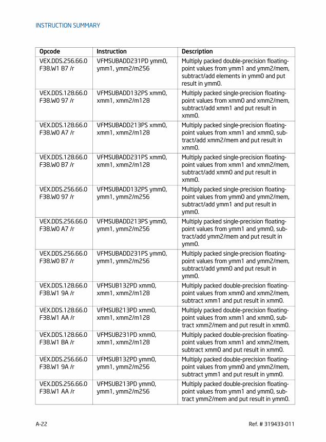
INSTRUCTION SUMMARY
VEX.DDS.256.66.0F38.W1 B7 /r
VFMSUBADD231PD ymm0, ymm1, ymm2/m256
Multiply packed double-precision floating-point values from ymm1 and ymm2/mem, subtract/add elements in ymm0 and put result in ymm0.
VEX.DDS.128.66.0F38.W0 97 /r
VFMSUBADD132PS xmm0, xmm1, xmm2/m128
Multiply packed single-precision floating-point values from xmm0 and xmm2/mem, subtract/add xmm1 and put result in xmm0.
VEX.DDS.128.66.0F38.W0 A7 /r
VFMSUBADD213PS xmm0, xmm1, xmm2/m128
Multiply packed single-precision floating-point values from xmm1 and xmm0, sub-tract/add xmm2/mem and put result in xmm0.
VEX.DDS.128.66.0F38.W0 B7 /r
VFMSUBADD231PS xmm0, xmm1, xmm2/m128
Multiply packed single-precision floating-point values from xmm1 and xmm2/mem, subtract/add xmm0 and put result in xmm0.
VEX.DDS.256.66.0F38.W0 97 /r
VFMSUBADD132PS ymm0, ymm1, ymm2/m256
Multiply packed single-precision floating-point values from ymm0 and ymm2/mem, subtract/add ymm1 and put result in ymm0.
VEX.DDS.256.66.0F38.W0 A7 /r
VFMSUBADD213PS ymm0, ymm1, ymm2/m256
Multiply packed single-precision floating-point values from ymm1 and ymm0, sub-tract/add ymm2/mem and put result in ymm0.
VEX.DDS.256.66.0F38.W0 B7 /r
VFMSUBADD231PS ymm0, ymm1, ymm2/m256
Multiply packed single-precision floating-point values from ymm1 and ymm2/mem, subtract/add ymm0 and put result in ymm0.
VEX.DDS.128.66.0F38.W1 9A /r
VFMSUB132PD xmm0, xmm1, xmm2/m128
Multiply packed double-precision floating-point values from xmm0 and xmm2/mem, subtract xmm1 and put result in xmm0.
VEX.DDS.128.66.0F38.W1 AA /r
VFMSUB213PD xmm0, xmm1, xmm2/m128
Multiply packed double-precision floating-point values from xmm1 and xmm0, sub-tract xmm2/mem and put result in xmm0.
VEX.DDS.128.66.0F38.W1 BA /r
VFMSUB231PD xmm0, xmm1, xmm2/m128
Multiply packed double-precision floating-point values from xmm1 and xmm2/mem, subtract xmm0 and put result in xmm0.
VEX.DDS.256.66.0F38.W1 9A /r
VFMSUB132PD ymm0, ymm1, ymm2/m256
Multiply packed double-precision floating-point values from ymm0 and ymm2/mem, subtract ymm1 and put result in ymm0.
VEX.DDS.256.66.0F38.W1 AA /r
VFMSUB213PD ymm0, ymm1, ymm2/m256
Multiply packed double-precision floating-point values from ymm1 and ymm0, sub-tract ymm2/mem and put result in ymm0.
Opcode Instruction Description
A-22 Ref. # 319433-011

INSTRUCTION SUMMARY
VEX.DDS.256.66.0F38.W1 BA /r
VFMSUB231PD ymm0, ymm1, ymm2/m256
Multiply packed double-precision floating-point values from ymm1 and ymm2/mem, subtract ymm0 and put result in ymm0.
VEX.DDS.128.66.0F38.W0 9A /r
VFMSUB132PS xmm0, xmm1, xmm2/m128
Multiply packed single-precision floating-point values from xmm0 and xmm2/mem, subtract xmm1 and put result in xmm0.
VEX.DDS.128.66.0F38.W0 AA /r
VFMSUB213PS xmm0, xmm1, xmm2/m128
Multiply packed single-precision floating-point values from xmm1 and xmm0, sub-tract xmm2/mem and put result in xmm0.
VEX.DDS.128.66.0F38.W0 BA /r
VFMSUB231PS xmm0, xmm1, xmm2/m128
Multiply packed single-precision floating-point values from xmm1 and xmm2/mem, subtract xmm0 and put result in xmm0.
VEX.DDS.256.66.0F38.W0 9A /r
VFMSUB132PS ymm0, ymm1, ymm2/m256
Multiply packed single-precision floating-point values from ymm0 and ymm2/mem, subtract ymm1 and put result in ymm0.
VEX.DDS.256.66.0F38.W0 AA /r
VFMSUB213PS ymm0, ymm1, ymm2/m256
Multiply packed single-precision floating-point values from ymm1 and ymm0, sub-tract ymm2/mem and put result in ymm0.
VEX.DDS.256.66.0F38.W0 BA /r
VFMSUB231PS ymm0, ymm1, ymm2/m256
Multiply packed single-precision floating-point values from ymm1 and ymm2/mem, subtract ymm0 and put result in ymm0.
VEX.DDS.128.66.0F38.W1 9B /r
VFMSUB132SD xmm0, xmm1, xmm2/m64
Multiply scalar double-precision floating-point value in xmm0 and xmm2/mem, subtract xmm1 and put result in xmm0.
VEX.DDS.128.66.0F38.W1 AB /r
VFMSUB213SD xmm0, xmm1, xmm2/m64
Multiply scalar double-precision floating-point value in xmm1 and xmm0, subtract xmm2/mem and put result in xmm0.
VEX.DDS.128.66.0F38.W1 BB /r
VFMSUB231SD xmm0, xmm1, xmm2/m64
Multiply scalar double-precision floating-point value in xmm1 and xmm2/mem, subtract xmm0 and put result in xmm0.
VEX.DDS.128.66.0F38.W0 9B /r
VFMSUB132SS xmm0, xmm1, xmm2/m32
Multiply scalar single-precision floating-point value in xmm0 and xmm2/mem, subtract xmm1 and put result in xmm0.
VEX.DDS.128.66.0F38.W0 AB /r
VFMSUB213SS xmm0, xmm1, xmm2/m32
Multiply scalar single-precision floating-point value in xmm1 and xmm0, subtract xmm2/mem and put result in xmm0.
VEX.DDS.128.66.0F38.W0 BB /r
VFMSUB231SS xmm0, xmm1, xmm2/m32
Multiply scalar single-precision floating-point value in xmm1 and xmm2/mem, subtract xmm0 and put result in xmm0.
Opcode Instruction Description
Ref. # 319433-011 A-23

INSTRUCTION SUMMARY
VEX.DDS.128.66.0F38.W1 9C /r
VFNMADD132PD xmm0, xmm1, xmm2/m128
Multiply packed double-precision floating-point values from xmm0 and xmm2/mem, negate the multiplication result and add to xmm1. Put the result in xmm0.
VEX.DDS.128.66.0F38.W1 AC /r
VFNMADD213PD xmm0, xmm1, xmm2/m128
Multiply packed double-precision floating-point values from xmm1 and xmm0, negate the multiplication result and add to xmm2/mem. Put the result in xmm0.
VEX.DDS.128.66.0F38.W1 BC /r
VFNMADD231PD xmm0, xmm1, xmm2/m128
Multiply packed double-precision floating-point values from xmm1 and xmm2/mem, negate the multiplication result and add to xmm0. Put the result in xmm0.
VEX.DDS.256.66.0F38.W1 9C /r
VFNMADD132PD ymm0, ymm1, ymm2/m256
Multiply packed double-precision floating-point values from ymm0 and ymm2/mem, negate the multiplication result and add to ymm1. Put the result in ymm0.
VEX.DDS.256.66.0F38.W1 AC /r
VFNMADD213PD ymm0, ymm1, ymm2/m256
Multiply packed double-precision floating-point values from ymm1 and ymm0, negate the multiplication result and add to ymm2/mem. Put the result in ymm0.
VEX.DDS.256.66.0F38.W1 BC /r
VFNMADD231PD ymm0, ymm1, ymm2/m256
Multiply packed double-precision floating-point values from ymm1 and ymm2/mem, negate the multiplication result and add to ymm0. Put the result in ymm0.
VEX.DDS.128.66.0F38.W0 9C /r
VFNMADD132PS xmm0, xmm1, xmm2/m128
Multiply packed single-precision floating-point values from xmm0 and xmm2/mem, negate the multiplication result and add to xmm1. Put the result in xmm0.
VEX.DDS.128.66.0F38.W0 AC /r
VFNMADD213PS xmm0, xmm1, xmm2/m128
Multiply packed single-precision floating-point values from xmm1 and xmm0, negate the multiplication result and add to xmm2/mem. Put the result in xmm0.
VEX.DDS.128.66.0F38.W0 BC /r
VFNMADD231PS xmm0, xmm1, xmm2/m128
Multiply packed single-precision floating-point values from xmm1 and xmm2/mem, negate the multiplication result and add to xmm0. Put the result in xmm0.
VEX.DDS.256.66.0F38.W0 9C /r
VFNMADD132PS ymm0, ymm1, ymm2/m256
Multiply packed single-precision floating-point values from ymm0 and ymm2/mem, negate the multiplication result and add to ymm1. Put the result in ymm0.
Opcode Instruction Description
A-24 Ref. # 319433-011

INSTRUCTION SUMMARY
VEX.DDS.256.66.0F38.W0 AC /r
VFNMADD213PS ymm0, ymm1, ymm2/m256
Multiply packed single-precision floating-point values from ymm1 and ymm0, negate the multiplication result and add to ymm2/mem. Put the result in ymm0.
VEX.DDS.256.66.0F38.W0 BC /r
VFNMADD231PS ymm0, ymm1, ymm2/m256
Multiply packed single-precision floating-point values from ymm1 and ymm2/mem, negate the multiplication result and add to ymm0. Put the result in ymm0.
VEX.DDS.128.66.0F38.W1 9D /r
VFNMADD132SD xmm0, xmm1, xmm2/m64
Multiply scalar double-precision floating-point value in xmm0 and xmm2/mem, negate the multiplication result and add to xmm1. Put the result in xmm0.
VEX.DDS.128.66.0F38.W1 AD /r
VFNMADD213SD xmm0, xmm1, xmm2/m64
Multiply scalar double-precision floating-point value in xmm1 and xmm0, negate the multiplication result and add to xmm2/mem. Put the result in xmm0.
VEX.DDS.128.66.0F38.W1 BD /r
VFNMADD231SD xmm0, xmm1, xmm2/m64
Multiply scalar double-precision floating-point value in xmm1 and xmm2/mem, negate the multiplication result and add to xmm0. Put the result in xmm0.
VEX.DDS.128.66.0F38.W0 9D /r
VFNMADD132SS xmm0, xmm1, xmm2/m32
Multiply scalar single-precision floating-point value in xmm0 and xmm2/mem, negate the multiplication result and add to xmm1. Put the result in xmm0.
VEX.DDS.128.66.0F38.W0 AD /r
VFNMADD213SS xmm0, xmm1, xmm2/m32
Multiply scalar single-precision floating-point value in xmm1 and xmm0, negate the multiplication result and add to xmm2/mem. Put the result in xmm0.
VEX.DDS.128.66.0F38.W0 BD /r
VFNMADD231SS xmm0, xmm1, xmm2/m32
Multiply scalar single-precision floating-point value in xmm1 and xmm2/mem, negate the multiplication result and add to xmm0. Put the result in xmm0.
VEX.DDS.128.66.0F38.W1 9E /r
VFNMSUB132PD xmm0, xmm1, xmm2/m128
Multiply packed double-precision floating-point values from xmm0 and xmm2/mem, negate the multiplication result and sub-tract xmm1. Put the result in xmm0.
VEX.DDS.128.66.0F38.W1 AE /r
VFNMSUB213PD xmm0, xmm1, xmm2/m128
Multiply packed double-precision floating-point values from xmm1 and xmm0, negate the multiplication result and sub-tract xmm2/mem. Put the result in xmm0.
Opcode Instruction Description
Ref. # 319433-011 A-25

INSTRUCTION SUMMARY
VEX.DDS.128.66.0F38.W1 BE /r
VFNMSUB231PD xmm0, xmm1, xmm2/m128
Multiply packed double-precision floating-point values from xmm1 and xmm2/mem, negate the multiplication result and sub-tract xmm0. Put the result in xmm0.
VEX.DDS.256.66.0F38.W1 9E /r
VFNMSUB132PD ymm0, ymm1, ymm2/m256
Multiply packed double-precision floating-point values from ymm0 and ymm2/mem, negate the multiplication result and sub-tract ymm1. Put the result in ymm0.
VEX.DDS.256.66.0F38.W1 AE /r
VFNMSUB213PD ymm0, ymm1, ymm2/m256
Multiply packed double-precision floating-point values from ymm1 and ymm0, negate the multiplication result and sub-tract ymm2/mem. Put the result in ymm0.
VEX.DDS.256.66.0F38.W1 BE /r
VFNMSUB231PD ymm0, ymm1, ymm2/m256
Multiply packed double-precision floating-point values from ymm1 and ymm2/mem, negate the multiplication result and sub-tract ymm0. Put the result in ymm0.
VEX.DDS.128.66.0F38.W0 9E /r
VFNMSUB132PS xmm0, xmm1, xmm2/m128
Multiply packed single-precision floating-point values from xmm0 and xmm2/mem, negate the multiplication result and sub-tract xmm1. Put the result in xmm0.
VEX.DDS.128.66.0F38.W0 AE /r
VFNMSUB213PS xmm0, xmm1, xmm2/m128
Multiply packed single-precision floating-point values from xmm1 and xmm0, negate the multiplication result and sub-tract xmm2/mem. Put the result in xmm0.
VEX.DDS.128.66.0F38.W0 BE /r
VFNMSUB231PS xmm0, xmm1, xmm2/m128
Multiply packed single-precision floating-point values from xmm1 and xmm2/mem, negate the multiplication result and sub-tract xmm0. Put the result in xmm0.
VEX.DDS.256.66.0F38.W0 9E /r
VFNMSUB132PS ymm0, ymm1, ymm2/m256
Multiply packed single-precision floating-point values from ymm0 and ymm2/mem, negate the multiplication result and sub-tract ymm1. Put the result in ymm0.
VEX.DDS.256.66.0F38.W0 AE /r
VFNMSUB213PS ymm0, ymm1, ymm2/m256
Multiply packed single-precision floating-point values from ymm1 and ymm0, negate the multiplication result and sub-tract ymm2/mem. Put the result in ymm0.
VEX.DDS.256.66.0F38.W0 BE /r
VFNMSUB231PS ymm0, ymm1, ymm2/m256
Multiply packed single-precision floating-point values from ymm1 and ymm2/mem, negate the multiplication result and sub-tract ymm0. Put the result in ymm0.
Opcode Instruction Description
A-26 Ref. # 319433-011
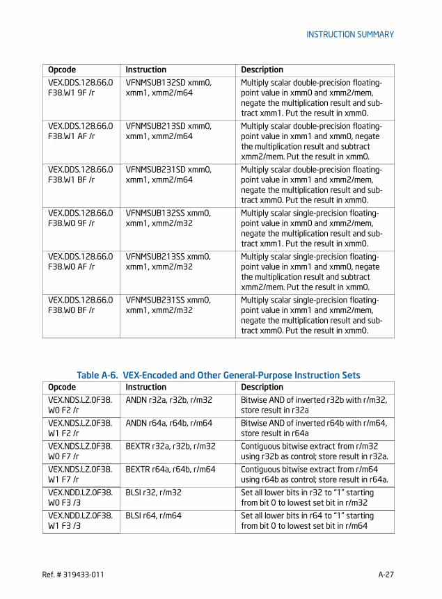
INSTRUCTION SUMMARY
Table A-6. VEX-Encoded and Other General-Purpose Instruction Sets
VEX.DDS.128.66.0F38.W1 9F /r
VFNMSUB132SD xmm0, xmm1, xmm2/m64
Multiply scalar double-precision floating-point value in xmm0 and xmm2/mem, negate the multiplication result and sub-tract xmm1. Put the result in xmm0.
VEX.DDS.128.66.0F38.W1 AF /r
VFNMSUB213SD xmm0, xmm1, xmm2/m64
Multiply scalar double-precision floating-point value in xmm1 and xmm0, negate the multiplication result and subtract xmm2/mem. Put the result in xmm0.
VEX.DDS.128.66.0F38.W1 BF /r
VFNMSUB231SD xmm0, xmm1, xmm2/m64
Multiply scalar double-precision floating-point value in xmm1 and xmm2/mem, negate the multiplication result and sub-tract xmm0. Put the result in xmm0.
VEX.DDS.128.66.0F38.W0 9F /r
VFNMSUB132SS xmm0, xmm1, xmm2/m32
Multiply scalar single-precision floating-point value in xmm0 and xmm2/mem, negate the multiplication result and sub-tract xmm1. Put the result in xmm0.
VEX.DDS.128.66.0F38.W0 AF /r
VFNMSUB213SS xmm0, xmm1, xmm2/m32
Multiply scalar single-precision floating-point value in xmm1 and xmm0, negate the multiplication result and subtract xmm2/mem. Put the result in xmm0.
VEX.DDS.128.66.0F38.W0 BF /r
VFNMSUB231SS xmm0, xmm1, xmm2/m32
Multiply scalar single-precision floating-point value in xmm1 and xmm2/mem, negate the multiplication result and sub-tract xmm0. Put the result in xmm0.
Opcode Instruction Description
VEX.NDS.LZ.0F38.W0 F2 /r
ANDN r32a, r32b, r/m32 Bitwise AND of inverted r32b with r/m32, store result in r32a
VEX.NDS.LZ.0F38.W1 F2 /r
ANDN r64a, r64b, r/m64 Bitwise AND of inverted r64b with r/m64, store result in r64a
VEX.NDS.LZ.0F38.W0 F7 /r
BEXTR r32a, r32b, r/m32 Contiguous bitwise extract from r/m32 using r32b as control; store result in r32a.
VEX.NDS.LZ.0F38.W1 F7 /r
BEXTR r64a, r64b, r/m64 Contiguous bitwise extract from r/m64 using r64b as control; store result in r64a.
VEX.NDD.LZ.0F38.W0 F3 /3
BLSI r32, r/m32 Set all lower bits in r32 to “1” starting from bit 0 to lowest set bit in r/m32
VEX.NDD.LZ.0F38.W1 F3 /3
BLSI r64, r/m64 Set all lower bits in r64 to “1” starting from bit 0 to lowest set bit in r/m64
Opcode Instruction Description
Ref. # 319433-011 A-27

INSTRUCTION SUMMARY
VEX.NDD.LZ.0F38.W0 F3 /2
BLSMSK r32, r/m32 Extract lowest bit from r/m32 and set that bit in r32
VEX.NDD.LZ.0F38.W1 F3 /2
BLSMSK r64, r/m64 Extract lowest bit from r/m64 and set that bit in r64
VEX.NDD.LZ.0F38.W0 F3 /1
BLSR r32, r/m32 Reset lowest set bit of r/m32, keep all other bits of r/m32 and write result to r32
VEX.NDD.LZ.0F38.W1 F3 /1
BLSR r64, r/m64 Reset lowest set bit of r/m64, keep all other bits of r/m64 and write result to r64
VEX.NDS.LZ.0F38.W0 F5 /r
BZHI r32a, r32b, r/m32 Zero bits in r/m32 starting with the posi-tion in r32b, write result to r32a.
VEX.NDS.LZ.0F38.W1 F5 /r
BZHI r64a, r64b, r/m64 Zero bits in r/m64 starting with the posi-tion in r64b, write result to r64a.
F3 0F BD /r LZCNT r16, r/m16 Count the number of leading zero bits in r/m16, return result in r16
F3 0F BD /r LZCNT r32, r/m32 Count the number of leading zero bits in r/m32, return result in r32
REX.W + F3 0F BD /r
LZCNT r64, r/m64 Count the number of leading zero bits in r/m64, return result in r64.
VEX.NDD.LZ.F2.0F38.W0 F6 /r
MULX r32a, r32b, r/m32 Unsigned multiply of r/m32 with EDX without affecting arithmetic flags.
VEX.NDD.LZ.F2.0F38.W1 F6 /r
MULX r64a, r64b, r/m64 Unsigned multiply of r/m64 with RDX without affecting arithmetic flags.
VEX.NDS.LZ.F2.0F38.W0 F5 /r
PDEP r32a, r32b, r/m32 Parallel deposit of bits from r32b using mask in r/m32, result is written to r32a.
VEX.NDS.LZ.F2.0F38.W1 F5 /r
PDEP r64a, r64b, r/m64 Parallel deposit of bits from r64b using mask in r/m64, result is written to r64a
VEX.NDS.LZ.F3.0F38.W0 F5 /r
PEXT r32a, r32b, r/m32 Parallel extract of bits from r32b using mask in r/m32, result is written to r32a.
VEX.NDS.LZ.F3.0F38.W1 F5 /r
PEXT r64a, r64b, r/m64 Parallel extract of bits from r64b using mask in r/m64, result is written to r64a
VEX.LZ.0F3A.W0 F0 /r ib
RORX r32, r/m32, imm8 Rotate 32-bit r/m32 right imm8 times without affecting arithmetic flags.
VEX.LZ.0F3A.W1 F0 /r ib
RORX r64, r/m64, imm8 Rotate 64-bit r/m64 right imm8 times without affecting arithmetic flags.
VEX.NDS.LZ.F3.0F38.W0 F7 /r
SARX r32a, r32b, r/m32 Shift r/m32 arithmetically right with count specified in r32b.
VEX.NDS.LZ.F3.0F38.W1 F7 /r
SARX r64a, r64b, r/m64 Shift r/m64 arithmetically right with count specified in r64b.
Opcode Instruction Description
A-28 Ref. # 319433-011
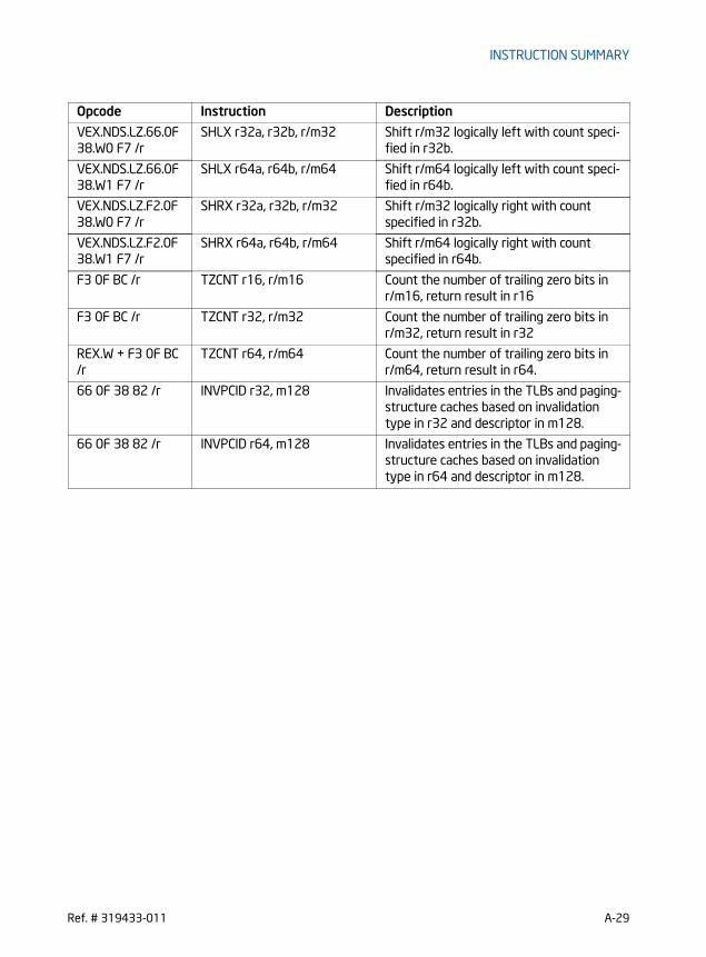
INSTRUCTION SUMMARY
VEX.NDS.LZ.66.0F38.W0 F7 /r
SHLX r32a, r32b, r/m32 Shift r/m32 logically left with count speci-fied in r32b.
VEX.NDS.LZ.66.0F38.W1 F7 /r
SHLX r64a, r64b, r/m64 Shift r/m64 logically left with count speci-fied in r64b.
VEX.NDS.LZ.F2.0F38.W0 F7 /r
SHRX r32a, r32b, r/m32 Shift r/m32 logically right with count specified in r32b.
VEX.NDS.LZ.F2.0F38.W1 F7 /r
SHRX r64a, r64b, r/m64 Shift r/m64 logically right with count specified in r64b.
F3 0F BC /r TZCNT r16, r/m16 Count the number of trailing zero bits in r/m16, return result in r16
F3 0F BC /r TZCNT r32, r/m32 Count the number of trailing zero bits in r/m32, return result in r32
REX.W + F3 0F BC /r
TZCNT r64, r/m64 Count the number of trailing zero bits in r/m64, return result in r64.
66 0F 38 82 /r INVPCID r32, m128 Invalidates entries in the TLBs and paging-structure caches based on invalidation type in r32 and descriptor in m128.
66 0F 38 82 /r INVPCID r64, m128 Invalidates entries in the TLBs and paging-structure caches based on invalidation type in r64 and descriptor in m128.
Opcode Instruction Description
Ref. # 319433-011 A-29

INSTRUCTION SUMMARY
Table A-7. New Instructions Introduced in Processors Code Named Ivy Bridge Opcode Instruction Description
F3 0F AE /0 RDFSBASE r32 Read FS base register and place the 32-bit result in the destination register.
REX.W + F3 0F AE /0
RDFSBASE r64 Read FS base register and place the 64-bit result in the destination register.
F3 0F AE /1 RDGSBASE r32 Read GS base register and place the 32-bit result in destination register.
REX.W + F3 0F AE /1
RDGSBASE r64 Read GS base register and place the 64-bit result in destination register.
0F C7 /6 RDRAND r16 Read a 16-bit random number and store in the destination register.
0F C7 /6 RDRAND r32 Read a 32-bit random number and store in the destination register.
REX.W + 0F C7 /6 RDRAND r64 Read a 64-bit random number and store in the destination register.
F3 0F AE /2 WRFSBASE r32 Write the 32-bit value in the source regis-ter to FS base register.
REX.W + F3 0F AE /2
WRFSBASE r64 Write the 64-bit value in the source regis-ter to FS base register.
F3 0F AE /3 WRGSBASE r32 Write the 32-bit value in the source regis-ter to GS base register.
REX.W + F3 0F AE /3
WRGSBASE r64 Write the 64-bit value in the source regis-ter to GS base register.
VEX.256.66.0F38.W0 13 /r
VCVTPH2PS ymm1, xmm2/m128
Convert eight packed half precision (16-bit) floating-point values in xmm2/m128 to packed single-precision floating-point value in ymm1.
VEX.128.66.0F38.W0 13 /r
VCVTPH2PS xmm1, xmm2/m64
Convert four packed half precision (16-bit) floating-point values in xmm2/m64 to packed single-precision floating-point value in xmm1.
VEX.256.66.0F3A.W0 1D /r ib
VCVTPS2PH xmm1/m128, ymm2, imm8
Convert eight packed single-precision floating-point value in ymm2 to packed half-precision (16-bit) floating-point value in xmm1/mem. Imm8 provides rounding controls.
VEX.128.66.0F3A.W0.1D /r ib
VCVTPS2PH xmm1/m64, xmm2, imm8
Convert four packed single-precision float-ing-point value in xmm2 to packed half-precision (16-bit) floating-point value in xmm1/mem. Imm8 provides rounding con-trols.
A-30 Ref. # 319433-011

INSTRUCTION SUMMARY
This page was
intentionally left
blank.
Ref. # 319433-011 A-31

OPCODE MAP
APPENDIX BOPCODE MAP
Use the opcode tables in this chapter to interpret IA-32 and Intel 64 architecture object code. Instructions are divided into encoding groups:• 1-byte, 2-byte and 3-byte opcode encodings are used to encode integer, system,
MMX technology, SSE/SSE2/SSE3/SSSE3/SSE4, and VMX instructions. Maps for these instructions are given in Table B-2 through Table B-6.
• Escape opcodes (in the format: ESC character, opcode, ModR/M byte) are used for floating-point instructions. The maps for these instructions are provided in Table B-7 through Table B-22.
NOTE
All blanks in opcode maps are reserved and must not be used. Do not depend on the operation of undefined or blank opcodes.
B.1 USING OPCODE TABLESTables in this appendix list opcodes of instructions (including required instruction prefixes, opcode extensions in associated ModR/M byte). Blank cells in the tables indicate opcodes that are reserved or undefined.
The opcode map tables are organized by hex values of the upper and lower 4 bits of an opcode byte. For 1-byte encodings (Table B-2), use the four high-order bits of an opcode to index a row of the opcode table; use the four low-order bits to index a column of the table. For 2-byte opcodes beginning with 0FH (Table B-3), skip any instruction prefixes, the 0FH byte (0FH may be preceded by 66H, F2H, or F3H) and use the upper and lower 4-bit values of the next opcode byte to index table rows and columns. Similarly, for 3-byte opcodes beginning with 0F38H or 0F3AH (Table B-4), skip any instruction prefixes, 0F38H or 0F3AH and use the upper and lower 4-bit values of the third opcode byte to index table rows and columns. See Section B.2.4, “Opcode Look-up Examples for One, Two, and Three-Byte Opcodes.”
When a ModR/M byte provides opcode extensions, this information qualifies opcode execution. For information on how an opcode extension in the ModR/M byte modifies the opcode map in Table B-2 and Table B-3, see Section B.4.
The escape (ESC) opcode tables for floating point instructions identify the eight high order bits of opcodes at the top of each page. See Section B.5. If the accompanying ModR/M byte is in the range of 00H-BFH, bits 3-5 (the top row of the third table on each page) along with the reg bits of ModR/M determine the opcode. ModR/M bytes
B-1Ref. # 319433-011

OPCODE MAP
outside the range of 00H-BFH are mapped by the bottom two tables on each page of the section.
B.2 KEY TO ABBREVIATIONSOperands are identified by a two-character code of the form Zz. The first character, an uppercase letter, specifies the addressing method; the second character, a lower-case letter, specifies the type of operand.
B.2.1 Codes for Addressing MethodThe following abbreviations are used to document addressing methods:
A Direct address: the instruction has no ModR/M byte; the address of the operand is encoded in the instruction. No base register, index register, or scaling factor can be applied (for example, far JMP (EA)).
B The VEX.vvvv field of the VEX prefix selects a general register.
C The reg field of the ModR/M byte selects a control register (for example, MOV (0F20, 0F22)).
D The reg field of the ModR/M byte selects a debug register (for example, MOV (0F21,0F23)).
E A ModR/M byte follows the opcode and specifies the operand. The operand is either a general-purpose register or a memory address. If it is a memory address, the address is computed from a segment register and any of the following values: a base register, an index register, a scaling factor, a displacement.
F EFLAGS/RFLAGS Register.
G The reg field of the ModR/M byte selects a general register (for example, AX (000)).
H The VEX.vvvv field of the VEX prefix selects a 128-bit XMM register or a 256-bit YMM register, determined by operand type. For legacy SSE encodings this operand does not exist, changing the instruction to destructive form.
I Immediate data: the operand value is encoded in subsequent bytes of the instruction.
J The instruction contains a relative offset to be added to the instruction pointer register (for example, JMP (0E9), LOOP).
L The upper 4 bits of the 8-bit immediate selects a 128-bit XMM register or a 256-bit YMM register, determined by operand type. (the MSB is ignored in 32-bit mode)
B-2Ref. # 319433-011

OPCODE MAP
M The ModR/M byte may refer only to memory (for example, BOUND, LES, LDS, LSS, LFS, LGS, CMPXCHG8B).
N The R/M field of the ModR/M byte selects a packed-quadword, MMX tech-nology register.
O The instruction has no ModR/M byte. The offset of the operand is coded as a word or double word (depending on address size attribute) in the instruction. No base register, index register, or scaling factor can be applied (for example, MOV (A0–A3)).
P The reg field of the ModR/M byte selects a packed quadword MMX technology register.
Q A ModR/M byte follows the opcode and specifies the operand. The operand is either an MMX technology register or a memory address. If it is a memory address, the address is computed from a segment register and any of the following values: a base register, an index register, a scaling factor, and a displacement.
R The R/M field of the ModR/M byte may refer only to a general register (for example, MOV (0F20-0F23)).
S The reg field of the ModR/M byte selects a segment register (for example, MOV (8C,8E)).
U The R/M field of the ModR/M byte selects a 128-bit XMM register or a 256-bit YMM register, determined by operand type.
V The reg field of the ModR/M byte selects a 128-bit XMM register or a 256-bit YMM register, determined by operand type.
W A ModR/M byte follows the opcode and specifies the operand. The operand is either a 128-bit XMM register, a 256-bit YMM register (determined by operand type), or a memory address. If it is a memory address, the address is computed from a segment register and any of the following values: a base register, an index register, a scaling factor, and a displacement.
X Memory addressed by the DS:rSI register pair (for example, MOVS, CMPS, OUTS, or LODS).
Y Memory addressed by the ES:rDI register pair (for example, MOVS, CMPS, INS, STOS, or SCAS).
B.2.2 Codes for Operand TypeThe following abbreviations are used to document operand types:
a Two one-word operands in memory or two double-word operands in memory, depending on operand-size attribute (used only by the BOUND instruction).
b Byte, regardless of operand-size attribute.
c Byte or word, depending on operand-size attribute.
B-3Ref. # 319433-011

OPCODE MAP
d Doubleword, regardless of operand-size attribute.
dq Double-quadword, regardless of operand-size attribute.
p 32-bit, 48-bit, or 80-bit pointer, depending on operand-size attribute.
pd 128-bit or 256-bit packed double-precision floating-point data.
pi Quadword MMX technology register (for example: mm0).
ps 128-bit or 256-bit packed single-precision floating-point data.
q Quadword, regardless of operand-size attribute.
qq Quad-Quadword (256-bits), regardless of operand-size attribute.
s 6-byte or 10-byte pseudo-descriptor.
sd Scalar element of a 128-bit double-precision floating data.
ss Scalar element of a 128-bit single-precision floating data.
si Doubleword integer register (for example: eax).
v Word, doubleword or quadword (in 64-bit mode), depending on operand-size attribute.
w Word, regardless of operand-size attribute.
x dq or qq based on the operand-size attribute.
y Doubleword or quadword (in 64-bit mode), depending on operand-size attribute.
z Word for 16-bit operand-size or doubleword for 32 or 64-bit operand-size.
B.2.3 Register CodesWhen an opcode requires a specific register as an operand, the register is identified by name (for example, AX, CL, or ESI). The name indicates whether the register is 64, 32, 16, or 8 bits wide.
A register identifier of the form eXX or rXX is used when register width depends on the operand-size attribute. eXX is used when 16 or 32-bit sizes are possible; rXX is used when 16, 32, or 64-bit sizes are possible. For example: eAX indicates that the AX register is used when the operand-size attribute is 16 and the EAX register is used when the operand-size attribute is 32. rAX can indicate AX, EAX or RAX.
When the REX.B bit is used to modify the register specified in the reg field of the opcode, this fact is indicated by adding “/x” to the register name to indicate the addi-tional possibility. For example, rCX/r9 is used to indicate that the register could either be rCX or r9. Note that the size of r9 in this case is determined by the operand size attribute (just as for rCX).
B-4Ref. # 319433-011

OPCODE MAP
B.2.4 Opcode Look-up Examples for One, Two, and Three-Byte Opcodes
This section provides examples that demonstrate how opcode maps are used.
B.2.4.1 One-Byte Opcode InstructionsThe opcode map for 1-byte opcodes is shown in Table B-2. The opcode map for 1-byte opcodes is arranged by row (the least-significant 4 bits of the hexadecimal value) and column (the most-significant 4 bits of the hexadecimal value). Each entry in the table lists one of the following types of opcodes:• Instruction mnemonics and operand types using the notations listed in Section
B.2• Opcodes used as an instruction prefix
For each entry in the opcode map that corresponds to an instruction, the rules for interpreting the byte following the primary opcode fall into one of the following cases:• A ModR/M byte is required and is interpreted according to the abbreviations listed
in Section B.1 and Chapter 2, “Instruction Format,” of the Intel® 64 and IA-32 Architectures Software Developer’s Manual, Volume 2A. Operand types are listed according to notations listed in Section B.2.
• A ModR/M byte is required and includes an opcode extension in the reg field in the ModR/M byte. Use Table B-6 when interpreting the ModR/M byte.
• Use of the ModR/M byte is reserved or undefined. This applies to entries that represent an instruction prefix or entries for instructions without operands that use ModR/M (for example: 60H, PUSHA; 06H, PUSH ES).
Example B-1. Look-up Example for 1-Byte Opcodes
Opcode 030500000000H for an ADD instruction is interpreted using the 1-byte opcode map (Table B-2) as follows:• The first digit (0) of the opcode indicates the table row and the second digit (3)
indicates the table column. This locates an opcode for ADD with two operands. • The first operand (type Gv) indicates a general register that is a word or
doubleword depending on the operand-size attribute. The second operand (type Ev) indicates a ModR/M byte follows that specifies whether the operand is a word or doubleword general-purpose register or a memory address.
• The ModR/M byte for this instruction is 05H, indicating that a 32-bit displacement follows (00000000H). The reg/opcode portion of the ModR/M byte (bits 3-5) is 000, indicating the EAX register.
The instruction for this opcode is ADD EAX, mem_op, and the offset of mem_op is 00000000H.
B-5Ref. # 319433-011
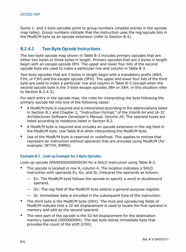
OPCODE MAP
Some 1- and 2-byte opcodes point to group numbers (shaded entries in the opcode map table). Group numbers indicate that the instruction uses the reg/opcode bits in the ModR/M byte as an opcode extension (refer to Section B.4).
B.2.4.2 Two-Byte Opcode InstructionsThe two-byte opcode map shown in Table B-3 includes primary opcodes that are either two bytes or three bytes in length. Primary opcodes that are 2 bytes in length begin with an escape opcode 0FH. The upper and lower four bits of the second opcode byte are used to index a particular row and column in Table B-3.
Two-byte opcodes that are 3 bytes in length begin with a mandatory prefix (66H, F2H, or F3H) and the escape opcode (0FH). The upper and lower four bits of the third byte are used to index a particular row and column in Table B-3 (except when the second opcode byte is the 3-byte escape opcodes 38H or 3AH; in this situation refer to Section B.2.4.3).
For each entry in the opcode map, the rules for interpreting the byte following the primary opcode fall into one of the following cases:• A ModR/M byte is required and is interpreted according to the abbreviations listed
in Section B.1 and Chapter 2, “Instruction Format,” of the Intel® 64 and IA-32 Architectures Software Developer’s Manual, Volume 2A. The operand types are listed according to notations listed in Section B.2.
• A ModR/M byte is required and includes an opcode extension in the reg field in the ModR/M byte. Use Table B-6 when interpreting the ModR/M byte.
• Use of the ModR/M byte is reserved or undefined. This applies to entries that represent an instruction without operands that are encoded using ModR/M (for example: 0F77H, EMMS).
Example B-2. Look-up Example for 2-Byte Opcodes
Look-up opcode 0FA4050000000003H for a SHLD instruction using Table B-3.• The opcode is located in row A, column 4. The location indicates a SHLD
instruction with operands Ev, Gv, and Ib. Interpret the operands as follows:
— Ev: The ModR/M byte follows the opcode to specify a word or doubleword operand.
— Gv: The reg field of the ModR/M byte selects a general-purpose register.
— Ib: Immediate data is encoded in the subsequent byte of the instruction.• The third byte is the ModR/M byte (05H). The mod and opcode/reg fields of
ModR/M indicate that a 32-bit displacement is used to locate the first operand in memory and eAX as the second operand.
• The next part of the opcode is the 32-bit displacement for the destination memory operand (00000000H). The last byte stores immediate byte that provides the count of the shift (03H).
B-6Ref. # 319433-011

OPCODE MAP
• By this breakdown, it has been shown that this opcode represents the instruction: SHLD DS:00000000H, EAX, 3.
B.2.4.3 Three-Byte Opcode InstructionsThe three-byte opcode maps shown in Table B-4 and Table B-5 includes primary opcodes that are either 3 or 4 bytes in length. Primary opcodes that are 3 bytes in length begin with two escape bytes 0F38H or 0F3A. The upper and lower four bits of the third opcode byte are used to index a particular row and column in Table B-4 or Table B-5.
Three-byte opcodes that are 4 bytes in length begin with a mandatory prefix (66H, F2H, or F3H) and two escape bytes (0F38H or 0F3AH). The upper and lower four bits of the fourth byte are used to index a particular row and column in Table B-4 or Table B-5.
For each entry in the opcode map, the rules for interpreting the byte following the primary opcode fall into the following case:• A ModR/M byte is required and is interpreted according to the abbreviations listed
in B.1 and Chapter 2, “Instruction Format,” of the Intel® 64 and IA-32 Architec-tures Software Developer’s Manual, Volume 2A. The operand types are listed according to notations listed in Section B.2.
Example B-3. Look-up Example for 3-Byte Opcodes
Look-up opcode 660F3A0FC108H for a PALIGNR instruction using Table B-5.• 66H is a prefix and 0F3AH indicate to use Table B-5. The opcode is located in row
0, column F indicating a PALIGNR instruction with operands Vdq, Wdq, and Ib. Interpret the operands as follows:
— Vdq: The reg field of the ModR/M byte selects a 128-bit XMM register.
— Wdq: The R/M field of the ModR/M byte selects either a 128-bit XMM register or memory location.
— Ib: Immediate data is encoded in the subsequent byte of the instruction.• The next byte is the ModR/M byte (C1H). The reg field indicates that the first
operand is XMM0. The mod shows that the R/M field specifies a register and the R/M indicates that the second operand is XMM1.
• The last byte is the immediate byte (08H).• By this breakdown, it has been shown that this opcode represents the
instruction: PALIGNR XMM0, XMM1, 8.
B.2.4.4 VEX Prefix InstructionsInstructions that include a VEX prefix are organized relative to the 2-byte and 3-byte opcode maps, based on the VEX.mmmmm field encoding of implied 0F, 0F38H,
B-7Ref. # 319433-011
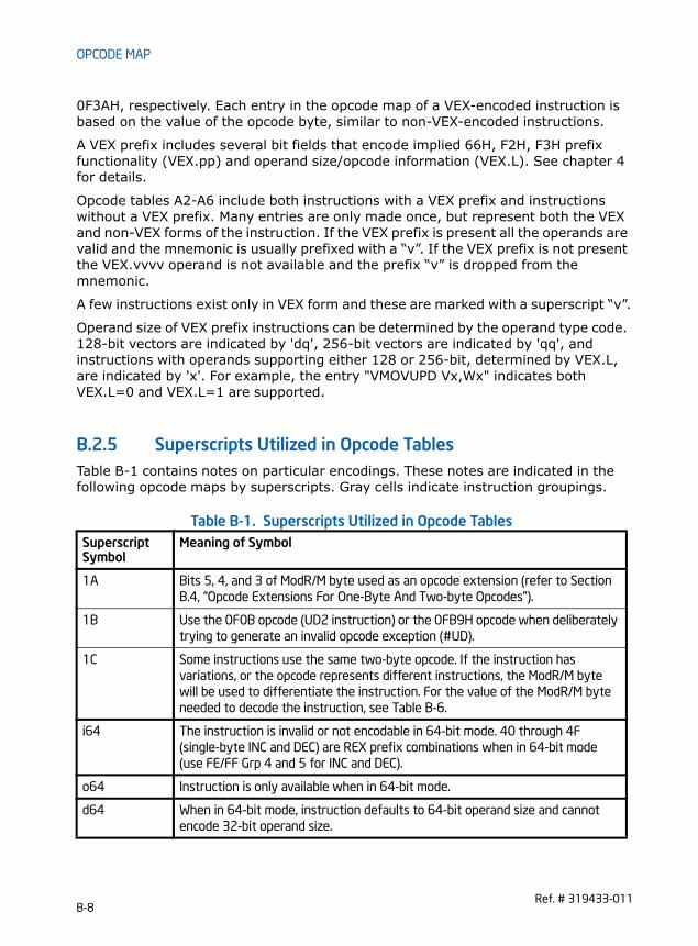
OPCODE MAP
0F3AH, respectively. Each entry in the opcode map of a VEX-encoded instruction is based on the value of the opcode byte, similar to non-VEX-encoded instructions.
A VEX prefix includes several bit fields that encode implied 66H, F2H, F3H prefix functionality (VEX.pp) and operand size/opcode information (VEX.L). See chapter 4 for details.
Opcode tables A2-A6 include both instructions with a VEX prefix and instructions without a VEX prefix. Many entries are only made once, but represent both the VEX and non-VEX forms of the instruction. If the VEX prefix is present all the operands are valid and the mnemonic is usually prefixed with a “v”. If the VEX prefix is not present the VEX.vvvv operand is not available and the prefix “v” is dropped from the mnemonic.
A few instructions exist only in VEX form and these are marked with a superscript “v”.
Operand size of VEX prefix instructions can be determined by the operand type code. 128-bit vectors are indicated by 'dq', 256-bit vectors are indicated by 'qq', and instructions with operands supporting either 128 or 256-bit, determined by VEX.L, are indicated by 'x'. For example, the entry "VMOVUPD Vx,Wx" indicates both VEX.L=0 and VEX.L=1 are supported.
B.2.5 Superscripts Utilized in Opcode TablesTable B-1 contains notes on particular encodings. These notes are indicated in the following opcode maps by superscripts. Gray cells indicate instruction groupings.
Table B-1. Superscripts Utilized in Opcode TablesSuperscriptSymbol
Meaning of Symbol
1A Bits 5, 4, and 3 of ModR/M byte used as an opcode extension (refer to Section B.4, “Opcode Extensions For One-Byte And Two-byte Opcodes”).
1B Use the 0F0B opcode (UD2 instruction) or the 0FB9H opcode when deliberately trying to generate an invalid opcode exception (#UD).
1C Some instructions use the same two-byte opcode. If the instruction has variations, or the opcode represents different instructions, the ModR/M byte will be used to differentiate the instruction. For the value of the ModR/M byte needed to decode the instruction, see Table B-6.
i64 The instruction is invalid or not encodable in 64-bit mode. 40 through 4F (single-byte INC and DEC) are REX prefix combinations when in 64-bit mode (use FE/FF Grp 4 and 5 for INC and DEC).
o64 Instruction is only available when in 64-bit mode.
d64 When in 64-bit mode, instruction defaults to 64-bit operand size and cannot encode 32-bit operand size.
B-8Ref. # 319433-011

OPCODE MAP
B.3 ONE, TWO, AND THREE-BYTE OPCODE MAPSSee Table B-2 through Table B-5 below. The tables are multiple page presentations. Rows and columns with sequential relationships are placed on facing pages to make look-up tasks easier. Note that table footnotes are not presented on each page. Table footnotes for each table are presented on the last page of the table.
f64 The operand size is forced to a 64-bit operand size when in 64-bit mode (prefixes that change operand size are ignored for this instruction in 64-bit mode).
v VEX form only exists. There is no legacy SSE form of the instruction. For Integer GPR instructions it means VEX prefix required.
v1 VEX128 & SSE forms only exist (no VEX256), when can’t be inferred from the data size.
Table B-1. Superscripts Utilized in Opcode TablesSuperscriptSymbol
Meaning of Symbol
B-9Ref. # 319433-011

OPCODE MAP
Table B-2. One-byte Opcode Map: (00H — F7H) *
0 1 2 3 4 5 6 7
0 ADD PUSHESi64
POPESi64
Eb, Gb Ev, Gv Gb, Eb Gv, Ev AL, Ib rAX, Iz
1 ADC PUSHSSi64
POPSSi64
Eb, Gb Ev, Gv Gb, Eb Gv, Ev AL, Ib rAX, Iz
2 AND SEG=ES(Prefix)
DAAi64
Eb, Gb Ev, Gv Gb, Eb Gv, Ev AL, Ib rAX, Iz
3 XOR SEG=SS(Prefix)
AAAi64
Eb, Gb Ev, Gv Gb, Eb Gv, Ev AL, Ib rAX, Iz
4 INCi64 general register / REXo64 Prefixes
eAXREX
eCXREX.B
eDXREX.X
eBXREX.XB
eSPREX.R
eBPREX.RB
eSIREX.RX
eDIREX.RXB
5 PUSHd64 general register
rAX/r8 rCX/r9 rDX/r10 rBX/r11 rSP/r12 rBP/r13 rSI/r14 rDI/r15
6 PUSHAi64/PUSHADi64
POPAi64/POPADi64
BOUNDi64
Gv, MaARPLi64
Ew, GwMOVSXDo64
Gv, Ev
SEG=FS(Prefix)
SEG=GS(Prefix)
OperandSize
(Prefix)
AddressSize
(Prefix)
7 Jccf64, Jb - Short-displacement jump on condition
O NO B/NAE/C NB/AE/NC Z/E NZ/NE BE/NA NBE/A
8 Immediate Grp 11A TEST XCHG
Eb, Ib Ev, Iz Eb, Ibi64 Ev, Ib Eb, Gb Ev, Gv Eb, Gb Ev, Gv
9 NOP PAUSE(F3)
XCHG r8, rAX
XCHG word, double-word or quad-word register with rAX
rCX/r9 rDX/r10 rBX/r11 rSP/r12 rBP/r13 rSI/r14 rDI/r15
A MOV MOVS/BYb, Xb
MOVS/W/D/QYv, Xv
CMPS/BXb, Yb
CMPS/W/DXv, Yv
AL, Ob rAX, Ov Ob, AL Ov, rAX
B MOV immediate byte into byte register
AL/R8L, Ib CL/R9L, Ib DL/R10L, Ib BL/R11L, Ib AH/R12L, Ib CH/R13L, Ib DH/R14L, Ib BH/R15L, Ib
C Shift Grp 21A RETNf64
IwRETNf64 LESi64
Gz, Mp VEX+2byte
LDSi64
Gz, Mp VEX+1byte
Grp 111A - MOV
Eb, Ib Ev, Ib Eb, Ib Ev, Iz
D Shift Grp 21A AAMi64
IbAADi64
IbXLAT/XLATB
Eb, 1 Ev, 1 Eb, CL Ev, CL
E LOOPNEf64/LOOPNZf64
Jb
LOOPEf64/LOOPZf64
Jb
LOOPf64
Jb JrCXZf64/
Jb IN OUT
AL, Ib eAX, Ib Ib, AL Ib, eAX
F LOCK(Prefix)
REPNE
(Prefix)
REP/REPE
(Prefix)
HLT CMC Unary Grp 31A
Eb Ev
B-10Ref. # 319433-011

OPCODE MAP
Table A-2. One-byte Opcode Map: (08H — FFH) *
8 9 A B C D E F
0 OR PUSHCSi64
2-byteescape
(Table A-3) Eb, Gb Ev, Gv Gb, Eb Gv, Ev AL, Ib rAX, Iz
1 SBB PUSHDSi64
POPDSi64
Eb, Gb Ev, Gv Gb, Eb Gv, Ev AL, Ib rAX, Iz
2 SUB SEG=CS (Prefix)
DASi64
Eb, Gb Ev, Gv Gb, Eb Gv, Ev AL, Ib rAX, Iz
3 CMP SEG=DS (Prefix)
AASi64
Eb, Gb Ev, Gv Gb, Eb Gv, Ev AL, Ib rAX, Iz
4 DECi64 general register / REXo64 Prefixes
eAXREX.W
eCXREX.WB
eDXREX.WX
eBXREX.WXB
eSPREX.WR
eBPREX.WRB
eSIREX.WRX
eDI REX.WRXB
5 POPd64 into general register
rAX/r8 rCX/r9 rDX/r10 rBX/r11 rSP/r12 rBP/r13 rSI/r14 rDI/r15
6 PUSHd64
IzIMUL
Gv, Ev, IzPUSHd64
IbIMUL
Gv, Ev, IbINS/INSB
Yb, DX
INS/INSW/INSD
Yz, DX
OUTS/OUTSBDX, Xb
OUTS/OUTSW/OUTSDDX, Xz
7 Jccf64, Jb- Short displacement jump on condition
S NS P/PE NP/PO L/NGE NL/GE LE/NG NLE/G
8 MOV MOVEv, Sw
LEAGv, M
MOVSw, Ew
Grp 1A1A POPd64 Ev
Eb, Gb Ev, Gv Gb, Eb Gv, Ev
9 CBW/CWDE/CDQE
CWD/CDQ/CQO
CALLFi64
ApFWAIT/WAIT
PUSHF/D/Q d64/Fv
POPF/D/Q d64/Fv
SAHF LAHF
A TEST STOS/BYb, AL
STOS/W/D/QYv, rAX
LODS/BAL, Xb
LODS/W/D/QrAX, Xv
SCAS/BAL, Yb
SCAS/W/D/QrAX, Xv
AL, Ib rAX, Iz
B MOV immediate word or double into word, double, or quad register
rAX/r8, Iv rCX/r9, Iv rDX/r10, Iv rBX/r11, Iv rSP/r12, Iv rBP/r13, Iv rSI/r14, Iv rDI/r15 , Iv
C ENTER LEAVEd64 RETF RETF INT 3 INT INTOi64 IRET/D/Q
Iw, Ib Iw Ib
D ESC (Escape to coprocessor instruction set)
E CALLf64 JMP IN OUT
Jz nearf64
Jzfari64
Apshortf64
JbAL, DX eAX, DX DX, AL DX, eAX
F CLC STC CLI STI CLD STD INC/DEC INC/DEC
Grp 41A Grp 51A
NOTES:
* All blanks in all opcode maps are reserved and must not be used. Do not depend on the operation of undefined or reserved locations.
B-11Ref. # 319433-011

OPCODE MAP
Table B-3. Two-byte Opcode Map: 00H — 77H (First Byte is 0FH) *
pfx 0 1 2 3 4 5 6 7
0Grp 61A Grp 71A LAR
Gv, Ew LSL
Gv, Ew SYSCALLo64 CLTS SYSRETo64
1
vmovups vmovups vmovlpsVq, Hq, Mqvmovhlps
Vq, Hq, Uq
vmovlpsMq, Vq
vunpcklpsVx, Hx, Wx
vunpckhpsVx, Hx, Wx
vmovhpsv1
Vdq, Hq, Mq vmovlhps
Vdq, Hq, Uq
vmovhpsv1
Mq, Vq
66vmovupd vmovupd
Wpd,Vpdvmovlpd
Vq, Hq, MqvmovlpdMq, Vq
vunpcklpdVx,Hx,Wx
vunpckhpdVx,Hx,Wx
vmovhpdv1
Vdq, Hq, Mqvmovhpdv1
Mq, Vq
F3vmovss
Vx, Hx, Wssvmovss
Wss, Hx, Vssvmovsldup
Vx, Wxvmovshdup
Vx, Wx
F2vmovsd
Vx, Hx, Wsdvmovsd
Wsd, Hx, Vsdvmovddup
Vx, Wx
2 2
MOVRd, Cd
MOVRd, Dd
MOVCd, Rd
MOVDd, Rd
3 3WRMSR RDTSC RDMSR RDPMC SYSENTER SYSEXIT GETSEC
4 4
CMOVcc, (Gv, Ev) - Conditional Move
O NO B/C/NAE AE/NB/NC E/Z NE/NZ BE/NA A/NBE
5
vmovmskpsGy, Ups
vsqrtpsVps, Wps
vrsqrtpsVps, Wps
vrcppsVps, Wps
vandpsVps, Hps, Wps
vandnpsVps, Hps, Wps
vorpsVps, Hps, Wps
vxorpsVps, Hps, Wps
66vmovmskpd
Gy,Updvsqrtpd
Vpd, Wpdvandpd
Vpd, Hpd, Wpdvandnpd
Vpd, Hpd, Wpdvorpd
Vpd, Hpd, Wpdvxorpd
Vpd, Hpd, Wpd
F3vsqrtss
Vss, Hss, Wssvrsqrtss
Vss, Hss, Wssvrcpss
Vss, Hss, Wss
F2vsqrtsd
Vsd, Hsd, Wsd
6
punpcklbwPq, Qd
punpcklwdPq, Qd
punpckldqPq, Qd
packsswbPq, Qq
pcmpgtbPq, Qq
pcmpgtwPq, Qq
pcmpgtdPq, Qq
packuswbPq, Qq
66vpunpcklbwVx, Hx, Wx
vpunpcklwdVx, Hx, Wx
vpunpckldqVx, Hx, Wx
vpacksswbVx, Hx, Wx
vpcmpgtbVx, Hx, Wx
vpcmpgtwVx, Hx, Wx
vpcmpgtdVx, Hx, Wx
vpackuswbVx, Hx, Wx
F3
7
pshufwPq, Qq, Ib
(Grp 121A) (Grp 131A) (Grp 141A) pcmpeqbPq, Qq
pcmpeqwPq, Qq
pcmpeqdPq, Qq
emms vzeroupperv
vzeroallv
66vpshufd
Vx, Wx, IbvpcmpeqbVx, Hx, Wx
vpcmpeqwVx, Hx, Wx
vpcmpeqdVx, Hx, Wx
F3vpshufhwVx, Wx, Ib
F2vpshuflw
Vx, Wx, Ib
B-12Ref. # 319433-011

OPCODE MAP
Table A-3. Two-byte Opcode Map: 08H — 7FH (First Byte is 0FH) *
pfx 8 9 A B C D E F
0 INVD WBINVD 2-byte Illegal
OpcodesUD21B
NOP Ev
1
Prefetch1C
(Grp 161A)NOP Ev
2
vmovapsVps, Wps
vmovapsWps, Vps
cvtpi2psVps, Qpi
vmovntpsMps, Vps
cvttps2piPpi, Wps
cvtps2piPpi, Wps
vucomissVss, Wss
vcomissVss, Wss
66vmovapdVpd, Wpd
vmovapdWpd,Vpd
cvtpi2pdVpd, Qpi
vmovntpdMpd, Vpd
cvttpd2piPpi, Wpd
cvtpd2piQpi, Wpd
vucomisdVsd, Wsd
vcomisdVsd, Wsd
F3vcvtsi2ss
Vss, Hss, Eyvcvttss2siGy, Wss
vcvtss2siGy, Wss
F2vcvtsi2sd
Vsd, Hsd, Ey vcvttsd2siGy, Wsd
vcvtsd2siGy, Wsd
3 3 3-byte escape
(Table A-4) 3-byte escape
(Table A-5)
4 4
CMOVcc(Gv, Ev) - Conditional Move
S NS P/PE NP/PO L/NGE NL/GE LE/NG NLE/G
5
vaddpsVps, Hps, Wps
vmulpsVps, Hps, Wps
vcvtps2pdVpd, Wps
vcvtdq2psVps, Wdq
vsubps Vps, Hps, Wps
vminpsVps, Hps, Wps
vdivpsVps, Hps, Wps
vmaxpsVps, Hps, Wps
66vaddpd
Vpd, Hpd, Wpdvmulpd
Vpd, Hpd, Wpdvcvtpd2psVps, Wpd
vcvtps2dqVdq, Wps
vsubpdVpd, Hpd, Wpd
vminpdVpd, Hpd, Wpd
vdivpdVpd, Hpd, Wpd
vmaxpdVpd, Hpd, Wpd
F3vaddss
Vss, Hss, Wssvmulss
Vss, Hss, Wssvcvtss2sd
Vsd, Hx, Wssvcvttps2dqVdq, Wps
vsubssVss, Hss, Wss
vminssVss, Hss, Wss
vdivssVss, Hss, Wss
vmaxssVss, Hss, Wss
F2vaddsd
Vsd, Hsd, Wsd vmulsd
Vsd, Hsd, Wsd vcvtsd2ss
Vss, Hx, Wsd vsubsd
Vsd, Hsd, Wsd vminsd
Vsd, Hsd, Wsd vdivsd
Vsd, Hsd, Wsd vmaxsd
Vsd, Hsd, Wsd
6
punpckhbwPq, Qd
punpckhwdPq, Qd
punpckhdqPq, Qd
packssdwPq, Qd
movd/qPd, Ey
movqPq, Qq
66vpunpckhbwVx, Hx, Wx
vpunpckhwdVx, Hx, Wx
vpunpckhdqVx, Hx, Wx
vpackssdwVx, Hx, Wx
vpunpcklqdqVx, Hx, Wx
vpunpckhqdqVx, Hx, Wx
vmovd/qVy, Ey
vmovdqaVx, Wx
F3 vmovdquVx, Wx
7
VMREADEy, Gy
VMWRITEGy, Ey
movd/qEy, Pd
movqQq, Pq
66vhaddpd
Vpd, Hpd, Wpdvhsubpd
Vpd, Hpd, Wpdvmovd/qEy, Vy
vmovdqaWx,Vx
F3vmovqVq, Wq
vmovdquWx,Vx
F2vhaddps
Vps, Hps, Wpsvhsubps
Vps, Hps, Wps
B-13Ref. # 319433-011

OPCODE MAP
Table A-3. Two-byte Opcode Map: 80H — F7H (First Byte is 0FH) *
pfx 0 1 2 3 4 5 6 7
8
Jccf64, Jz - Long-displacement jump on condition
O NO B/CNAE AE/NB/NC E/Z NE/NZ BE/NA A/NBE
9
SETcc, Eb - Byte Set on condition
O NO B/C/NAE AE/NB/NC E/Z NE/NZ BE/NA A/NBE
APUSHd64
FSPOPd64
FSCPUID BT
Ev, Gv SHLD
Ev, Gv, Ib SHLD
Ev, Gv, CL
BCMPXCHG LSS
Gv, Mp BTR
Ev, Gv LFS
Gv, Mp LGS
Gv, Mp MOVZX
Eb, Gb Ev, Gv Gv, Eb Gv, Ew
C
XADDEb, Gb
XADDEv, Gv
vcmppsVps,Hps,Wps,Ib
movntiMy, Gy
pinsrwPq,Ry/Mw,Ib
pextrwGd, Nq, Ib
vshufpsVps,Hps,Wps,Ib
Grp 91A
66vcmppd
Vpd,Hpd,Wpd,Ibvpinsrw
Vdq,Hdq,Ry/Mw,Ibvpextrw
Gd, Udq, Ibvshufpd
Vpd,Hpd,Wpd,Ib
F3vcmpss
Vss,Hss,Wss,Ib
F2vcmpsd
Vsd,Hsd,Wsd,Ib
D
psrlwPq, Qq
psrldPq, Qq
psrlqPq, Qq
paddqPq, Qq
pmullwPq, Qq
pmovmskbGd, Nq
66vaddsubpd
Vpd, Hpd, Wpdvpsrlw
Vx, Hx, Wxvpsrld
Vx, Hx, Wxvpsrlq
Vx, Hx, Wxvpaddq
Vx, Hx, Wxvpmullw
Vx, Hx, WxvmovqWq, Vq
vpmovmskb Gd, Ux
F3movq2dqVdq, Nq
F2vaddsubps
Vps, Hps, Wpsmovdq2qPq, Uq
E
pavgbPq, Qq
psrawPq, Qq
psradPq, Qq
pavgwPq, Qq
pmulhuwPq, Qq
pmulhwPq, Qq
movntqMq, Pq
66vpavgb
Vx, Hx, Wxvpsraw
Vx, Hx, Wxvpsrad
Vx, Hx, Wxvpavgw
Vx, Hx, WxvpmulhuwVx, Hx, Wx
vpmulhwVx, Hx, Wx
vcvttpd2dqVx, Wpd
vmovntdqMx, Vx
F3vcvtdq2pdVx, Wpd
F2vcvtpd2dqVx, Wpd
F
psllwPq, Qq
pslldPq, Qq
psllqPq, Qq
pmuludqPq, Qq
pmaddwdPq, Qq
psadbwPq, Qq
maskmovqPq, Nq
66vpsllw
Vx, Hx, Wxvpslld
Vx, Hx, Wxvpsllq
Vx, Hx, Wxvpmuludq
Vx, Hx, Wxvpmaddwd Vx, Hx, Wx
vpsadbwVx, Hx, Wx
vmaskmovdquVx, Ux
F2vlddquVx, Mx
B-14Ref. # 319433-011
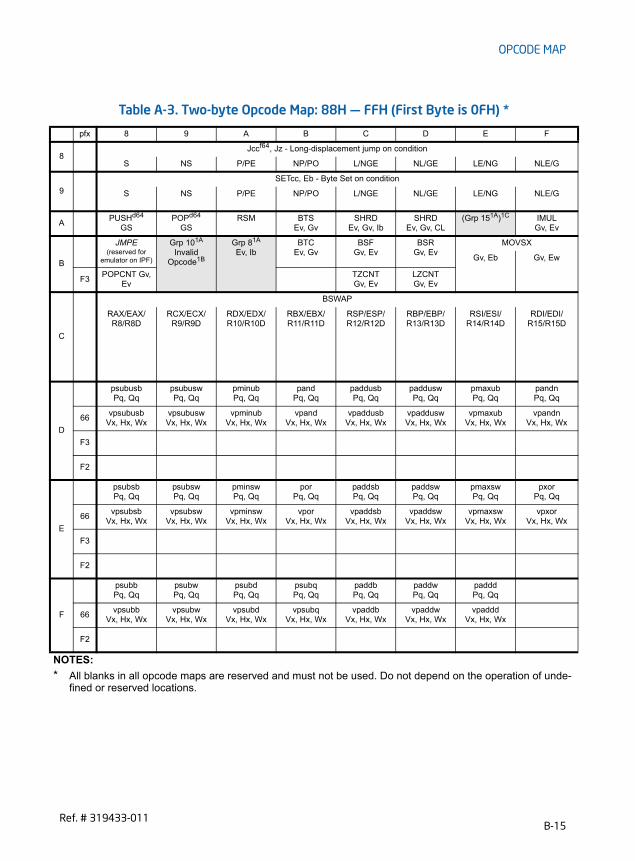
OPCODE MAP
Table A-3. Two-byte Opcode Map: 88H — FFH (First Byte is 0FH) *
pfx 8 9 A B C D E F
8 Jccf64, Jz - Long-displacement jump on condition
S NS P/PE NP/PO L/NGE NL/GE LE/NG NLE/G
9
SETcc, Eb - Byte Set on condition
S NS P/PE NP/PO L/NGE NL/GE LE/NG NLE/G
A PUSHd64
GSPOPd64
GSRSM BTS
Ev, Gv SHRD
Ev, Gv, Ib SHRD
Ev, Gv, CL (Grp 151A)1C IMUL
Gv, Ev
B
JMPE
(reserved for emulator on IPF)
Grp 101A
Invalid Opcode1B
Grp 81A
Ev, IbBTC
Ev, GvBSF
Gv, EvBSR
Gv, EvMOVSX
Gv, Eb Gv, Ew
F3POPCNT Gv,
EvTZCNT Gv, Ev
LZCNT Gv, Ev
C
BSWAP
RAX/EAX/R8/R8D
RCX/ECX/ R9/R9D
RDX/EDX/ R10/R10D
RBX/EBX/ R11/R11D
RSP/ESP/ R12/R12D
RBP/EBP/ R13/R13D
RSI/ESI/ R14/R14D
RDI/EDI/ R15/R15D
D
psubusbPq, Qq
psubuswPq, Qq
pminubPq, Qq
pandPq, Qq
paddusbPq, Qq
padduswPq, Qq
pmaxubPq, Qq
pandnPq, Qq
66vpsubusb
Vx, Hx, WxvpsubuswVx, Hx, Wx
vpminubVx, Hx, Wx
vpandVx, Hx, Wx
vpaddusbVx, Hx, Wx
vpadduswVx, Hx, Wx
vpmaxubVx, Hx, Wx
vpandnVx, Hx, Wx
F3
F2
E
psubsbPq, Qq
psubswPq, Qq
pminswPq, Qq
porPq, Qq
paddsbPq, Qq
paddswPq, Qq
pmaxswPq, Qq
pxorPq, Qq
66vpsubsb
Vx, Hx, Wxvpsubsw
Vx, Hx, Wxvpminsw
Vx, Hx, Wxvpor
Vx, Hx, Wxvpaddsb
Vx, Hx, Wxvpaddsw
Vx, Hx, Wxvpmaxsw
Vx, Hx, Wxvpxor
Vx, Hx, Wx
F3
F2
F
psubbPq, Qq
psubwPq, Qq
psubdPq, Qq
psubqPq, Qq
paddbPq, Qq
paddwPq, Qq
padddPq, Qq
66vpsubb
Vx, Hx, Wxvpsubw
Vx, Hx, Wx vpsubd
Vx, Hx, Wxvpsubq
Vx, Hx, Wxvpaddb
Vx, Hx, Wxvpaddw
Vx, Hx, Wx vpaddd
Vx, Hx, Wx
F2
NOTES:
* All blanks in all opcode maps are reserved and must not be used. Do not depend on the operation of unde-fined or reserved locations.
B-15Ref. # 319433-011
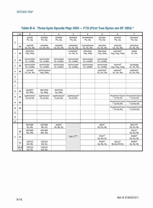
OPCODE MAP
Table B-4. Three-byte Opcode Map: 00H — F7H (First Two Bytes are 0F 38H) *
pfx 0 1 2 3 4 5 6 7
0
pshufbPq, Qq
phaddwPq, Qq
phadddPq, Qq
phaddswPq, Qq
pmaddubswPq, Qq
phsubwPq, Qq
phsubdPq, Qq
phsubswPq, Qq
66vpshufb
Vx, Hx, Wxvphaddw
Vx, Hx, Wxvphaddd
Vx, Hx, WxvphaddswVx, Hx, Wx
vpmaddubswVx, Hx, Wx
vphsubwVx, Hx, Wx
vphsubdVx, Hx, Wx
vphsubswVx, Hx, Wx
1 66pblendvbVdq, Wdq
vcvtph2psv
Vx, Wx, IbblendvpsVdq, Wdq
blendvpdVdq, Wdq
vpermpsv
Vqq, Hqq, WqqvptestVx, Wx
2 66vpmovsxbwVx, Ux/Mq
vpmovsxbdVx, Ux/Md
vpmovsxbqVx, Ux/Mw
vpmovsxwdVx, Ux/Mq
vpmovsxwqVx, Ux/Md
vpmovsxdqVx, Ux/Mq
3 66vpmovzxbwVx, Ux/Mq
vpmovzxbdVx, Ux/Md
vpmovzxbqVx, Ux/Mw
vpmovzxwdVx, Ux/Mq
vpmovzxwqVx, Ux/Md
vpmovzxdqVx, Ux/Mq
vpermdv
Vqq, Hqq, Wqqvpcmpgtq
Vx, Hx, Wx
4 66vpmulld
Vx, Hx, Wxvphminposuw
Vdq, Wdqvpsrlvd/qv
Vx, Hx, Wxvpsravdv
Vx, Hx, Wxvpsllvd/qv
Vx, Hx, Wx
5
6
7
8 66INVEPT Gy, Mdq
INVVPID Gy, Mdq
INVPCID Gy, Mdq
9 66vgatherdd/qv
Vx,Hx,Wxvgatherqd/qv
Vx,Hx,Wxvgatherdps/dv
Vx,Hx,Wxvgatherqps/dv
Vx,Hx,Wxvfmaddsub132ps/d
v Vx,Hx,Wxvfmsubadd132ps/d
v Vx,Hx,Wx
A 66vfmaddsub213ps/d
v Vx,Hx,Wxvfmsubadd213ps/d
v Vx,Hx,Wx
B 66vfmaddsub231ps/d
v Vx,Hx,Wxvfmsubadd231ps/d
v Vx,Hx,Wx
C
D
E
F
MOVBE Gy, My
MOVBE My, Gy
ANDNv
Gy, By, Ey
Grp 171A
BZHIv
Gy, Ey, ByBEXTRv
Gy, Ey, By
66MOVBE Gw, Mw
MOVBE Mw, Gw
SHLXv
Gy, Ey, By
F3PEXTv
Gy, By, EySARXv
Gy, Ey, By
F2CRC32 Gd, Eb
CRC32 Gd, Ey
PDEPv
Gy, By, EyMULXv
By,Gy,rDX,EySHRXv
Gy, Ey, By
66 & F2
CRC32 Gd, Eb
CRC32 Gd, Ew
B-16Ref. # 319433-011

OPCODE MAP
N
Table A-4. Three-byte Opcode Map: 08H — FFH (First Two Bytes are 0F 38H) *
pfx 8 9 A B C D E F
0
psignbPq, Qq
psignwPq, Qq
psigndPq, Qq
pmulhrswPq, Qq
66vpsignb
Vx, Hx, Wxvpsignw
Vx, Hx, Wxvpsignd
Vx, Hx, Wxvpmulhrsw Vx, Hx, Wx
vpermilpsv Vx,Hx,Wx
vpermilpdv Vx,Hx,Wx
vtestpsv Vx, Wx
vtestpdv Vx, Wx
1
pabsbPq, Qq
pabswPq, Qq
pabsdPq, Qq
66vbroadcastssv
Vx, Wdvbroadcastsdv
Vqq, Wqvbroadcastf128v
Vqq, MdqvpabsbVx, Wx
vpabswVx, Wx
vpabsdVx, Wx
2 66vpmuldq
Vx, Hx, WxvpcmpeqqVx, Hx, Wx
vmovntdqaVx, Mx
vpackusdwVx, Hx, Wx
vmaskmovpsv Vx,Hx,Mx
vmaskmovpdv Vx,Hx,Mx
vmaskmovpsv Mx,Hx,Vx
vmaskmovpdv Mx,Hx,Vx
3 66vpminsb
Vx, Hx, Wxvpminsd
Vx, Hx, Wxvpminuw
Vx, Hx, Wxvpminud
Vx, Hx, Wxvpmaxsb
Vx, Hx, Wxvpmaxsd
Vx, Hx, Wxvpmaxuw
Vx, Hx, Wxvpmaxud
Vx, Hx, Wx
4
5 66vpbroadcastdv
Vx, Wxvpbroadcastqv
Vx, Wxvbroadcasti128v
Vqq, Mdq
6
7 66vpbroadcastbv
Vx, Wxvpbroadcastwv
Vx, Wx
8 66vpmaskmovd/qv
Vx,Hx,Mxvpmaskmovd/qv
Mx,Vx,Hx
9 66vfmadd132ps/dv
Vx, Hx, Wxvfmadd132ss/dv
Vx, Hx, Wxvfmsub132ps/dv
Vx, Hx, Wxvfmsub132ss/dv
Vx, Hx, Wxvfnmadd132ps/d
v Vx, Hx, Wxvfnmadd132ss/dv
Vx, Hx, Wxvfnmsub132ps/dv
Vx, Hx, Wxvfnmsub132ss/dv
Vx, Hx, Wx
A 66vfmadd213ps/dv
Vx, Hx, Wxvfmadd213ss/dv
Vx, Hx, Wxvfmsub213ps/dv
Vx, Hx, Wxvfmsub213ss/dv
Vx, Hx, Wxvfnmadd213ps/d
v Vx, Hx, Wxvfnmadd213ss/dv
Vx, Hx, Wvfnmsub213ps/dv
Vx, Hx, Wxvfnmsub213ss/dv
Vx, Hx, Wx
B 66vfmadd231ps/dv
Vx, Hx, Wxvfmadd231ss/dv
Vx, Hx, Wxvfmsub231ps/dv
Vx, Hx, Wxvfmsub231ss/dv
Vx, Hx, Wxvfnmadd231ps/d
v Vx, Hx, Wxvfnmadd231ss/dv
Vx, Hx, Wxvfnmsub231ps/dv
Vx, Hx, Wxvfnmsub231ss/dv
Vx, Hx, Wx
C
D 66VAESIMC Vdq, Wdq
VAESENC Vdq,Hdq,Wdq
VAESENCLAST Vdq,Hdq,Wdq
VAESDEC Vdq,Hdq,Wdq
VAESDECLAST Vdq,Hdq,Wdq
E
F
66
F3
F2
66 & F2
OTES:
* All blanks in all opcode maps are reserved and must not be used. Do not depend on the operation of unde-fined or reserved locations.
B-17Ref. # 319433-011

OPCODE MAP
Table B-5. Three-byte Opcode Map: 00H — F7H (First two bytes are 0F 3AH) *
pfx 0 1 2 3 4 5 6 7
0 66
vpermqv
Vqq, Wqq, Ibvpermpdv
Vqq, Wqq, Ibvpblenddv
Vx,Hx,Wx,Ibvpermilpsv Vx, Wx, Ib
vpermilpdv Vx, Wx, Ib
vperm2f128v Vqq,Hqq,Wqq,Ib
1 66vpextrb
Rd/Mb, Vdq, Ibvpextrw
Rd/Mw, Vdq, Ibvpextrd/q
Ey, Vdq, Ib vextractps Ed, Vdq, Ib
2 66vpinsrb
Vdq,Hdq, Ry/Mb,Ib
vinsertpsVdq,Hdq, Udq/Md,Ib
vpinsrd/qVdq,Hdq,Ey,Ib
3
4 66vdpps
Vx,Hx,Wx,Ibvdppd
Vdq,Hdq,Wdq,Ibvmpsadbw
Vx,Hx,Wx,Ibvpclmulqdq
Vdq,Hdq,Wdq,Ibvperm2i128v
Vqq,Hqq,Wqq,Ib
5
6 66vpcmpestrmVdq, Wdq, Ib
vpcmpestri Vdq, Wdq, Ib
vpcmpistrm Vdq, Wdq, Ib
vpcmpistriVdq, Wdq, Ib
7
8
9
A
B
C
D
E
FF2
RORXv
By, Ey, Ib
B-18Ref. # 319433-011

OPCODE MAP
Table A-5. Three-byte Opcode Map: 08H — FFH (First Two Bytes are 0F 3AH) *
pfx 8 9 A B C D E F
0
palignrPq, Qq, Ib
66vroundpsVx,Wx,Ib
vroundpdVx,Wx,Ib
vroundssVss,Wss,Ib
vroundsdVsd,Wsd,Ib
vblendpsVx,Hx,Wx,Ib
vblendpdVx,Hx,Wx,Ib
vpblendwVx,Hx,Wx,Ib
vpalignrVx,Hx,Wx,Ib
1 66vinsertf128v
Vqq,Hqq,Wqq,Ibvextractf128v Wdq,Vqq,Ib
vcvtps2phvWx, Vx, Ib
2
3 66vinserti128v
Vqq,Hqq,Wqq,Ibvextracti128v Wdq,Vqq,Ib
4 66vblendvpsv
Vx,Hx,Wx,Lxvblendvpdv
Vx,Hx,Wx,Lxvpblendvbv
Vx,Hx,Wx,Lx
5
6
7
8
9
A
B
C
D 66VAESKEYGEN Vdq, Wdq, Ib
E
F
NOTES:
* All blanks in all opcode maps are reserved and must not be used. Do not depend on the operation of undefined or reserved locations.
B-19Ref. # 319433-011

OPCODE MAP
B.4 OPCODE EXTENSIONS FOR ONE-BYTE AND TWO-BYTE OPCODES
Some 1-byte and 2-byte opcodes use bits 3-5 of the ModR/M byte (the nnn field in Figure B-1) as an extension of the opcode.
Opcodes that have opcode extensions are indicated in Table B-6 and organized by group number. Group numbers (from 1 to 16, second column) provide a table entry point. The encoding for the r/m field for each instruction can be established using the third column of the table.
B.4.1 Opcode Look-up Examples Using Opcode ExtensionsAn Example is provided below.
Example B-4. Interpreting an ADD Instruction
An ADD instruction with a 1-byte opcode of 80H is a Group 1 instruction:• Table B-6 indicates that the opcode extension field encoded in the ModR/M byte
for this instruction is 000B. • The r/m field can be encoded to access a register (11B) or a memory address
using a specified addressing mode (for example: mem = 00B, 01B, 10B).
Example B-5. Looking Up 0F01C3H
Look up opcode 0F01C3 for a VMRESUME instruction by using Table B-2, Table B-3 and Table B-6:• 0F tells us that this instruction is in the 2-byte opcode map.• 01 (row 0, column 1 in Table B-3) reveals that this opcode is in Group 7 of Table
B-6.• C3 is the ModR/M byte. The first two bits of C3 are 11B. This tells us to look at the
second of the Group 7 rows in Table B-6.• The Op/Reg bits [5,4,3] are 000B. This tells us to look in the 000 column for
Group 7.• Finally, the R/M bits [2,1,0] are 011B. This identifies the opcode as the
VMRESUME instruction.
mod nnn R/M
Figure B-1. ModR/M Byte nnn Field (Bits 5, 4, and 3)
B-20Ref. # 319433-011

OPCODE MAP
is)
1P
R
VAX
PGb
GS00) (001)
C
RSTq
RSTq
B.4.2 Opcode Extension TablesSee Table B-6 below.
Table B-6. Opcode Extensions for One- and Two-byte Opcodes by Group Number *
Opcode Group Mod 7,6 pfx
Encoding of Bits 5,4,3 of the ModR/M Byte (bits 2,1,0 in parenthes000 001 010 011 100 101 110 11
80-83 1mem, 11B
ADD OR ADC SBB AND SUB XOR CM
8F 1Amem, 11B
POP
C0,C1 reg, immD0, D1 reg, 1
D2, D3 reg, CL2
mem, 11B
ROL ROR RCL RCR SHL/SAL SHR SA
F6, F7 3mem, 11B
TEST Ib/Iz
NOT NEG MULAL/rAX
IMULAL/rAX
DIVAL/rAX
IDIAL/r
FE 4mem, 11B
INCEb
DECEb
FF 5mem, 11B
INCEv
DECEv
CALLNf64
EvCALLF
Ep JMPNf64
EvJMPF
MpPUSHd64
Ev
0F 00 6mem, 11B
SLDTRv/Mw
STRRv/Mw
LLDTEw
LTREw
VERREw
VERWEw
0F 01 7
mem SGDTMs
SIDTMs
LGDTMs
LIDTMs
SMSWMw/Rv
LMSWEw
INVLM
11B VMCALL (001) VMLAUNCH
(010) VMRESUME
(011) VMXOFF
(100)
MONITOR (000)
MWAIT (001)
XGETBV (000)
XSETBV (001)
SWAPo64(0
RDTSCP
0F BA 8mem, 11B
BT BTS BTR BT
0F C7 9
mem
CMPXCH8B Mq
CMPXCHG16B Mdq
VMPTRLDMq
VMPTM
66 VMCLEARMq
F3 VMXONMq
VMPTM
11BRDRAND
Rv
0F B9 10mem
11B
C6
11
mem, 11B
MOVEb, Ib
C7mem MOV
Ev, Iz11B
B-21Ref. # 319433-011

OPCODE MAP
is)
1
ldqx,Ib
sh
ce
fined
Opcode Group Mod 7,6 pfx
Encoding of Bits 5,4,3 of the ModR/M Byte (bits 2,1,0 in parenthes000 001 010 011 100 101 110 11
0F 71 12
mem
11B
psrlwNq, Ib
psrawNq, Ib
psllwNq, Ib
66 vpsrlwHx,Ux,Ib
vpsrawHx,Ux,Ib
vpsllwHx,Ux,Ib
0F 72 13
mem
11B
psrldNq, Ib
psradNq, Ib
pslldNq, Ib
66 vpsrldHx,Ux,Ib
vpsradHx,Ux,Ib
vpslldHx,Ux,Ib
0F 73 14
mem
11B
psrlqNq, Ib
psllqNq, Ib
66 vpsrlqHx,Ux,Ib
vpsrldqHx,Ux,Ib
vpsllqHx,Ux,Ib
vpslHx,U
0F AE 15
mem fxsave fxrstor ldmxcsr stmxcsr XSAVE XRSTOR XSAVEOPT clflu
11B
lfence mfence sfen
F3 RDFSBASE Ry
RDGSBASE Ry
WRFSBASE Ry
WRGSBASE Ry
0F 18 16mem
prefetchNTA
prefetchT0
prefetchT1
prefetchT2
11B
VEX.0F38 F3 17mem F3 BLSRv
By, EyBLSMSKv
By, EyBLSIv
By, Ey11B F3
NOTES:
* All blanks in all opcode maps are reserved and must not be used. Do not depend on the operation of undeor reserved locations.
Table B-6. Opcode Extensions for One- and Two-byte Opcodes by Group Number *
B-22Ref. # 319433-011

OPCODE MAP
B.5 ESCAPE OPCODE INSTRUCTIONSOpcode maps for coprocessor escape instruction opcodes (x87 floating-point instruction opcodes) are in Table B-7 through Table B-22. These maps are grouped by the first byte of the opcode, from D8-DF. Each of these opcodes has a ModR/M byte. If the ModR/M byte is within the range of 00H-BFH, bits 3-5 of the ModR/M byte are used as an opcode extension, similar to the technique used for 1-and 2-byte opcodes (see B.4). If the ModR/M byte is outside the range of 00H through BFH, the entire ModR/M byte is used as an opcode extension.
B.5.1 Opcode Look-up Examples for Escape Instruction OpcodesExamples are provided below.
Example B-6. Opcode with ModR/M Byte in the 00H through BFH Range
DD0504000000H can be interpreted as follows:• The instruction encoded with this opcode can be located in Section . Since the
ModR/M byte (05H) is within the 00H through BFH range, bits 3 through 5 (000) of this byte indicate the opcode for an FLD double-real instruction (see Table B-9).
• The double-real value to be loaded is at 00000004H (the 32-bit displacement that follows and belongs to this opcode).
Example B-7. Opcode with ModR/M Byte outside the 00H through BFH Range
D8C1H can be interpreted as follows:• This example illustrates an opcode with a ModR/M byte outside the range of 00H
through BFH. The instruction can be located in Section B.4. • In Table B-8, the ModR/M byte C1H indicates row C, column 1 (the FADD
instruction using ST(0), ST(1) as operands).
B.5.2 Escape Opcode Instruction TablesTables are listed below.
B-23Ref. # 319433-011

OPCODE MAP
B.5.2.1 Escape Opcodes with D8 as First ByteTable B-7 and B-8 contain maps for the escape instruction opcodes that begin with D8H. Table B-7 shows the map if the ModR/M byte is in the range of 00H-BFH. Here, the value of bits 3-5 (the nnn field in Figure B-1) selects the instruction.
Table B-8 shows the map if the ModR/M byte is outside the range of 00H-BFH. Here, the first digit of the ModR/M byte selects the table row and the second digit selects the column.
Table B-7. D8 Opcode Map When ModR/M Byte is Within 00H to BFH *
nnn Field of ModR/M Byte (refer to Figure B.4)
000B 001B 010B 011B 100B 101B 110B 111B
FADD single-real
FMUL single-real
FCOM single-real
FCOMP single-real
FSUB single-real
FSUBR single-real
FDIV single-real FDIVR single-real
NOTES:
* All blanks in all opcode maps are reserved and must not be used. Do not depend on the operation of undefined or reserved locations.
Table B-8. D8 Opcode Map When ModR/M Byte is Outside 00H to BFH *0 1 2 3 4 5 6 7
C FADD
ST(0),ST(0) ST(0),ST(1) ST(0),ST(2) ST(0),ST(3) ST(0),ST(4) ST(0),ST(5) ST(0),ST(6) ST(0),ST(7)
D FCOM
ST(0),ST(0) ST(0),ST(1) ST(0),T(2) ST(0),ST(3) ST(0),ST(4) ST(0),ST(5) ST(0),ST(6) ST(0),ST(7)
E FSUB
ST(0),ST(0) ST(0),ST(1) ST(0),ST(2) ST(0),ST(3) ST(0),ST(4) ST(0),ST(5) ST(0),ST(6) ST(0),ST(7)
F FDIV
ST(0),ST(0) ST(0),ST(1) ST(0),ST(2) ST(0),ST(3) ST(0),ST(4) ST(0),ST(5) ST(0),ST(6) ST(0),ST(7)
8 9 A B C D E F
C FMUL
ST(0),ST(0) ST(0),ST(1) ST(0),ST(2) ST(0),ST(3) ST(0),ST(4) ST(0),ST(5) ST(0),ST(6) ST(0),ST(7)
D FCOMP
ST(0),ST(0) ST(0),ST(1) ST(0),T(2) ST(0),ST(3) ST(0),ST(4) ST(0),ST(5) ST(0),ST(6) ST(0),ST(7)
E FSUBR
ST(0),ST(0) ST(0),ST(1) ST(0),ST(2) ST(0),ST(3) ST(0),ST(4) ST(0),ST(5) ST(0),ST(6) ST(0),ST(7)
F FDIVR
ST(0),ST(0) ST(0),ST(1) ST(0),ST(2) ST(0),ST(3) ST(0),ST(4) ST(0),ST(5) ST(0),ST(6) ST(0),ST(7)
NOTES:
* All blanks in all opcode maps are reserved and must not be used. Do not depend on the operation of undefined or reserved locations.
B-24Ref. # 319433-011

OPCODE MAP
B.5.2.2 Escape Opcodes with D9 as First ByteTable B-9 and B-10 contain maps for escape instruction opcodes that begin with D9H. Table B-9 shows the map if the ModR/M byte is in the range of 00H-BFH. Here, the value of bits 3-5 (the nnn field in Figure B-1) selects the instruction..
Table B-10 shows the map if the ModR/M byte is outside the range of 00H-BFH. Here, the first digit of the ModR/M byte selects the table row and the second digit selects the column.
Table B-9. D9 Opcode Map When ModR/M Byte is Within 00H to BFH *nnn Field of ModR/M Byte
000B 001B 010B 011B 100B 101B 110B 111B
FLDsingle-real
FSTsingle-real
FSTPsingle-real
FLDENV14/28 bytes
FLDCW2 bytes
FSTENV14/28 bytes
FSTCW2 bytes
NOTES:
* All blanks in all opcode maps are reserved and must not be used. Do not depend on the operation of undefined or reserved locations.
Table B-10. D9 Opcode Map When ModR/M Byte is Outside 00H to BFH *0 1 2 3 4 5 6 7
C FLD
ST(0),ST(0) ST(0),ST(1) ST(0),ST(2) ST(0),ST(3) ST(0),ST(4) ST(0),ST(5) ST(0),ST(6) ST(0),ST(7)
D FNOP
E FCHS FABS FTST FXAM
F F2XM1 FYL2X FPTAN FPATAN FXTRACT FPREM1 FDECSTP FINCSTP
8 9 A B C D E F
C FXCH
ST(0),ST(0) ST(0),ST(1) ST(0),ST(2) ST(0),ST(3) ST(0),ST(4) ST(0),ST(5) ST(0),ST(6) ST(0),ST(7)
D
E FLD1 FLDL2T FLDL2E FLDPI FLDLG2 FLDLN2 FLDZ
F FPREM FYL2XP1 FSQRT FSINCOS FRNDINT FSCALE FSIN FCOS
NOTES:
* All blanks in all opcode maps are reserved and must not be used. Do not depend on the operation of undefined or reserved locations.
B-25Ref. # 319433-011

OPCODE MAP
B.5.2.3 Escape Opcodes with DA as First ByteTable B-11 and B-12 contain maps for escape instruction opcodes that begin with DAH. Table B-11 shows the map if the ModR/M byte is in the range of 00H-BFH. Here, the value of bits 3-5 (the nnn field in Figure B-1) selects the instruction.
Table B-11 shows the map if the ModR/M byte is outside the range of 00H-BFH. Here, the first digit of the ModR/M byte selects the table row and the second digit selects the column.
Table B-11. DA Opcode Map When ModR/M Byte is Within 00H to BFH *nnn Field of ModR/M Byte
000B 001B 010B 011B 100B 101B 110B 111B
FIADDdword-integer
FIMULdword-integer
FICOMdword-integer
FICOMPdword-integer
FISUBdword-integer
FISUBRdword-integer
FIDIVdword-integer
FIDIVRdword-integer
NOTES:
* All blanks in all opcode maps are reserved and must not be used. Do not depend on the operation of undefined or reserved locations.
Table B-12. DA Opcode Map When ModR/M Byte is Outside 00H to BFH *0 1 2 3 4 5 6 7
C FCMOVB
ST(0),ST(0) ST(0),ST(1) ST(0),ST(2) ST(0),ST(3) ST(0),ST(4) ST(0),ST(5) ST(0),ST(6) ST(0),ST(7)
D FCMOVBE
ST(0),ST(0) ST(0),ST(1) ST(0),ST(2) ST(0),ST(3) ST(0),ST(4) ST(0),ST(5) ST(0),ST(6) ST(0),ST(7)
E
F
8 9 A B C D E F
C FCMOVE
ST(0),ST(0) ST(0),ST(1) ST(0),ST(2) ST(0),ST(3) ST(0),ST(4) ST(0),ST(5) ST(0),ST(6) ST(0),ST(7)
D FCMOVU
ST(0),ST(0) ST(0),ST(1) ST(0),ST(2) ST(0),ST(3) ST(0),ST(4) ST(0),ST(5) ST(0),ST(6) ST(0),ST(7)
E FUCOMPP
F
NOTES:
* All blanks in all opcode maps are reserved and must not be used. Do not depend on the operation of undefined or reserved locations.
B-26Ref. # 319433-011

OPCODE MAP
B.5.2.4 Escape Opcodes with DB as First ByteTable B-13 and B-14 contain maps for escape instruction opcodes that begin with DBH. Table B-13 shows the map if the ModR/M byte is in the range of 00H-BFH. Here, the value of bits 3-5 (the nnn field in Figure B-1) selects the instruction.
Table B-14 shows the map if the ModR/M byte is outside the range of 00H-BFH. Here, the first digit of the ModR/M byte selects the table row and the second digit selects the column.
Table B-13. DB Opcode Map When ModR/M Byte is Within 00H to BFH *nnn Field of ModR/M Byte
000B 001B 010B 011B 100B 101B 110B 111B
FILDdword-integer
FISTTP dword-integer
FISTdword-integer
FISTPdword-integer
FLDextended-real
FSTPextended-real
NOTES:
* All blanks in all opcode maps are reserved and must not be used. Do not depend on the operation of undefined or reserved locations.
Table B-14. DB Opcode Map When ModR/M Byte is Outside 00H to BFH *0 1 2 3 4 5 6 7
C FCMOVNB
ST(0),ST(0) ST(0),ST(1) ST(0),ST(2) ST(0),ST(3) ST(0),ST(4) ST(0),ST(5) ST(0),ST(6) ST(0),ST(7)
D FCMOVNBE
ST(0),ST(0) ST(0),ST(1) ST(0),ST(2) ST(0),ST(3) ST(0),ST(4) ST(0),ST(5) ST(0),ST(6) ST(0),ST(7)
E FCLEX FINIT
F FCOMI
ST(0),ST(0) ST(0),ST(1) ST(0),ST(2) ST(0),ST(3) ST(0),ST(4) ST(0),ST(5) ST(0),ST(6) ST(0),ST(7)
8 9 A B C D E F
C FCMOVNE
ST(0),ST(0) ST(0),ST(1) ST(0),ST(2) ST(0),ST(3) ST(0),ST(4) ST(0),ST(5) ST(0),ST(6) ST(0),ST(7)
D FCMOVNU
ST(0),ST(0) ST(0),ST(1) ST(0),ST(2) ST(0),ST(3) ST(0),ST(4) ST(0),ST(5) ST(0),ST(6) ST(0),ST(7)
E FUCOMI
ST(0),ST(0) ST(0),ST(1) ST(0),ST(2) ST(0),ST(3) ST(0),ST(4) ST(0),ST(5) ST(0),ST(6) ST(0),ST(7)
F
NOTES:
* All blanks in all opcode maps are reserved and must not be used. Do not depend on the operation of undefined or reserved locations.
B-27Ref. # 319433-011

OPCODE MAP
B.5.2.5 Escape Opcodes with DC as First ByteTable B-15 and B-16 contain maps for escape instruction opcodes that begin with DCH. Table B-15 shows the map if the ModR/M byte is in the range of 00H-BFH. Here, the value of bits 3-5 (the nnn field in Figure B-1) selects the instruction.
Table B-16 shows the map if the ModR/M byte is outside the range of 00H-BFH. In this case the first digit of the ModR/M byte selects the table row and the second digit selects the column.
Table B-15. DC Opcode Map When ModR/M Byte is Within 00H to BFH *nnn Field of ModR/M Byte (refer to Figure B-1)
000B 001B 010B 011B 100B 101B 110B 111B
FADD double-real
FMUL double-real
FCOM double-real
FCOMP double-real
FSUB double-real
FSUBR double-real
FDIV double-real
FDIVR double-real
NOTES:
* All blanks in all opcode maps are reserved and must not be used. Do not depend on the operation of undefined or reserved locations.
Table B-16. DC Opcode Map When ModR/M Byte is Outside 00H to BFH *0 1 2 3 4 5 6 7
C FADD
ST(0),ST(0) ST(1),ST(0) ST(2),ST(0) ST(3),ST(0) ST(4),ST(0) ST(5),ST(0) ST(6),ST(0) ST(7),ST(0)
D
E FSUBR
ST(0),ST(0) ST(1),ST(0) ST(2),ST(0) ST(3),ST(0) ST(4),ST(0) ST(5),ST(0) ST(6),ST(0) ST(7),ST(0)
F FDIVR
ST(0),ST(0) ST(1),ST(0) ST(2),ST(0) ST(3),ST(0) ST(4),ST(0) ST(5),ST(0) ST(6),ST(0) ST(7),ST(0)
8 9 A B C D E F
C FMUL
ST(0),ST(0) ST(1),ST(0) ST(2),ST(0) ST(3),ST(0) ST(4),ST(0) ST(5),ST(0) ST(6),ST(0) ST(7),ST(0)
D
E FSUB
ST(0),ST(0) ST(1),ST(0) ST(2),ST(0) ST(3),ST(0) ST(4),ST(0) ST(5),ST(0) ST(6),ST(0) ST(7),ST(0)
F FDIV
ST(0),ST(0) ST(1),ST(0) ST(2),ST(0) ST(3),ST(0) ST(4),ST(0) ST(5),ST(0) ST(6),ST(0) ST(7),ST(0)
NOTES:
* All blanks in all opcode maps are reserved and must not be used. Do not depend on the operation of undefined or reserved locations.
B-28Ref. # 319433-011

OPCODE MAP
B.5.2.6 Escape Opcodes with DD as First ByteTable B-17 and B-18 contain maps for escape instruction opcodes that begin with DDH. Table B-17 shows the map if the ModR/M byte is in the range of 00H-BFH. Here, the value of bits 3-5 (the nnn field in Figure B-1) selects the instruction.
Table B-18 shows the map if the ModR/M byte is outside the range of 00H-BFH. The first digit of the ModR/M byte selects the table row and the second digit selects the column.
Table B-17. DD Opcode Map When ModR/M Byte is Within 00H to BFH *
nnn Field of ModR/M Byte
000B 001B 010B 011B 100B 101B 110B 111B
FLD double-real
FISTTP integer64
FST double-real
FSTP double-real
FRSTOR 98/108bytes
FSAVE 98/108bytes
FSTSW 2 bytes
NOTES:
* All blanks in all opcode maps are reserved and must not be used. Do not depend on the operation of undefined or reserved locations.
Table B-18. DD Opcode Map When ModR/M Byte is Outside 00H to BFH *0 1 2 3 4 5 6 7
C FFREE
ST(0) ST(1) ST(2) ST(3) ST(4) ST(5) ST(6) ST(7)
D FST
ST(0) ST(1) ST(2) ST(3) ST(4) ST(5) ST(6) ST(7)
E FUCOM
ST(0),ST(0) ST(1),ST(0) ST(2),ST(0) ST(3),ST(0) ST(4),ST(0) ST(5),ST(0) ST(6),ST(0) ST(7),ST(0)
F
8 9 A B C D E F
C
D FSTP
ST(0) ST(1) ST(2) ST(3) ST(4) ST(5) ST(6) ST(7)
E FUCOMP
ST(0) ST(1) ST(2) ST(3) ST(4) ST(5) ST(6) ST(7)
F
NOTES:
* All blanks in all opcode maps are reserved and must not be used. Do not depend on the operation of undefined or reserved locations.
B-29Ref. # 319433-011

OPCODE MAP
B.5.2.7 Escape Opcodes with DE as First ByteTable B-19 and B-20 contain opcode maps for escape instruction opcodes that begin with DEH. Table B-19 shows the opcode map if the ModR/M byte is in the range of 00H-BFH. In this case, the value of bits 3-5 (the nnn field in Figure B-1) selects the instruction.
Table B-20 shows the opcode map if the ModR/M byte is outside the range of 00H-BFH. The first digit of the ModR/M byte selects the table row and the second digit selects the column.
Table B-19. DE Opcode Map When ModR/M Byte is Within 00H to BFH *nnn Field of ModR/M Byte
000B 001B 010B 011B 100B 101B 110B 111B
FIADD word-integer
FIMUL word-integer
FICOM word-integer
FICOMP word-integer
FISUB word-integer
FISUBR word-integer
FIDIV word-integer
FIDIVR word-integer
NOTES:
* All blanks in all opcode maps are reserved and must not be used. Do not depend on the operation of undefined or reserved locations.
Table B-20. DE Opcode Map When ModR/M Byte is Outside 00H to BFH *0 1 2 3 4 5 6 7
C FADDP
ST(0),ST(0) ST(1),ST(0) ST(2),ST(0) ST(3),ST(0) ST(4),ST(0) ST(5),ST(0) ST(6),ST(0) ST(7),ST(0)
D
E FSUBRP
ST(0),ST(0) ST(1),ST(0) ST(2),ST(0) ST(3),ST(0) ST(4),ST(0) ST(5),ST(0) ST(6),ST(0) ST(7),ST(0)
F FDIVRP
ST(0),ST(0) ST(1),ST(0) ST(2),ST(0) ST(3),ST(0) ST(4),ST(0) ST(5),ST(0) ST(6),ST(0) ST(7),ST(0)
8 9 A B C D E F
C FMULP
ST(0),ST(0) ST(1),ST(0) ST(2),ST(0) ST(3),ST(0) ST(4),ST(0) ST(5),ST(0) ST(6),ST(0) ST(7),ST(0)
D FCOMPP
E FSUBP
ST(0),ST(0) ST(1),ST(0) ST(2),ST(0) ST(3),ST(0) ST(4),ST(0) ST(5),ST(0) ST(6),ST(0) ST(7),ST(0)
F FDIVP
ST(0),ST(0) ST(1),ST(0) ST(2),ST(0). ST(3),ST(0) ST(4),ST(0) ST(5),ST(0) ST(6),ST(0) ST(7),ST(0)
NOTES:
* All blanks in all opcode maps are reserved and must not be used. Do not depend on the operation of undefined or reserved locations.
B-30Ref. # 319433-011

OPCODE MAP
B.5.2.8 Escape Opcodes with DF As First ByteTable B-21 and B-22 contain the opcode maps for escape instruction opcodes that begin with DFH. Table B-21 shows the opcode map if the ModR/M byte is in the range of 00H-BFH. Here, the value of bits 3-5 (the nnn field in Figure B-1) selects the instruction.
Table B-22 shows the opcode map if the ModR/M byte is outside the range of 00H-BFH. The first digit of the ModR/M byte selects the table row and the second digit selects the column.
Table B-21. DF Opcode Map When ModR/M Byte is Within 00H to BFH *nnn Field of ModR/M Byte
000B 001B 010B 011B 100B 101B 110B 111B
FILDword-integer
FISTTPword-integer
FIST word-integer
FISTP word-integer
FBLD packed-BCD
FILD qword-integer
FBSTP packed-BCD
FISTP qword-integer
NOTES:
* All blanks in all opcode maps are reserved and must not be used. Do not depend on the operation of undefined or reserved locations.
Table B-22. DF Opcode Map When ModR/M Byte is Outside 00H to BFH *
0 1 2 3 4 5 6 7
C
D
E FSTSWAX
F FCOMIP
ST(0),ST(0) ST(0),ST(1) ST(0),ST(2) ST(0),ST(3) ST(0),ST(4) ST(0),ST(5) ST(0),ST(6) ST(0),ST(7)
8 9 A B C D E F
C
D
E FUCOMIP
ST(0),ST(0) ST(0),ST(1) ST(0),ST(2) ST(0),ST(3) ST(0),ST(4) ST(0),ST(5) ST(0),ST(6) ST(0),ST(7)
F
NOTES:
* All blanks in all opcode maps are reserved and must not be used. Do not depend on the operation of undefined or reserved locations.
B-31Ref. # 319433-011

INDEX
AADDPD - Add Packed Double Precision Floating-Point Values . . . . . . . . . . . . . . . . . . . . . . . . . . . .5-8
BBrand information . . . . . . . . . . . . . . . . . . . . . . . . . . . . . . . . . . . . . . . . . . . . . . . . . . . . . . . . . . . . . . . . .2-59
processor brand index . . . . . . . . . . . . . . . . . . . . . . . . . . . . . . . . . . . . . . . . . . . . . . . . . . . . . . . . . .2-63processor brand string . . . . . . . . . . . . . . . . . . . . . . . . . . . . . . . . . . . . . . . . . . . . . . . . . . . . . . . . . .2-60
CCache and TLB information . . . . . . . . . . . . . . . . . . . . . . . . . . . . . . . . . . . . . . . . . . . . . . . . . . . . . . . . .2-54Cache Inclusiveness . . . . . . . . . . . . . . . . . . . . . . . . . . . . . . . . . . . . . . . . . . . . . . . . . . . . . . . . . . . . . . .2-37CLFLUSH instruction
CPUID flag . . . . . . . . . . . . . . . . . . . . . . . . . . . . . . . . . . . . . . . . . . . . . . . . . . . . . . . . . . . . . . . . . . . . .2-53CMOVcc flag . . . . . . . . . . . . . . . . . . . . . . . . . . . . . . . . . . . . . . . . . . . . . . . . . . . . . . . . . . . . . . . . . . . . . .2-53CMOVcc instructions
CPUID flag . . . . . . . . . . . . . . . . . . . . . . . . . . . . . . . . . . . . . . . . . . . . . . . . . . . . . . . . . . . . . . . . . . . . .2-53CMPXCHG16B instruction
CPUID bit . . . . . . . . . . . . . . . . . . . . . . . . . . . . . . . . . . . . . . . . . . . . . . . . . . . . . . . . . . . . . . . . . . . . . .2-49CMPXCHG8B instruction
CPUID flag . . . . . . . . . . . . . . . . . . . . . . . . . . . . . . . . . . . . . . . . . . . . . . . . . . . . . . . . . . . . . . . . . . . . .2-52CPUID instruction . . . . . . . . . . . . . . . . . . . . . . . . . . . . . . . . . . . . . . . . . . . . . . . . . . . . . . . . . . . . 2-34, 2-53
36-bit page size extension. . . . . . . . . . . . . . . . . . . . . . . . . . . . . . . . . . . . . . . . . . . . . . . . . . . . . . .2-53APIC on-chip . . . . . . . . . . . . . . . . . . . . . . . . . . . . . . . . . . . . . . . . . . . . . . . . . . . . . . . . . . . . . . . . . . .2-52basic CPUID information . . . . . . . . . . . . . . . . . . . . . . . . . . . . . . . . . . . . . . . . . . . . . . . . . . . . . . . .2-35cache and TLB characteristics . . . . . . . . . . . . . . . . . . . . . . . . . . . . . . . . . . . . . . . . . . . . . . . 2-35, 2-54CLFLUSH flag . . . . . . . . . . . . . . . . . . . . . . . . . . . . . . . . . . . . . . . . . . . . . . . . . . . . . . . . . . . . . . . . . .2-53CLFLUSH instruction cache line size . . . . . . . . . . . . . . . . . . . . . . . . . . . . . . . . . . . . . . . . . . . . . .2-47CMPXCHG16B flag . . . . . . . . . . . . . . . . . . . . . . . . . . . . . . . . . . . . . . . . . . . . . . . . . . . . . . . . . . . . . .2-49CMPXCHG8B flag . . . . . . . . . . . . . . . . . . . . . . . . . . . . . . . . . . . . . . . . . . . . . . . . . . . . . . . . . . . . . . .2-52CPL qualified debug store . . . . . . . . . . . . . . . . . . . . . . . . . . . . . . . . . . . . . . . . . . . . . . . . . . . . . . .2-49debug extensions, CR4.DE . . . . . . . . . . . . . . . . . . . . . . . . . . . . . . . . . . . . . . . . . . . . . . . . . . . . . .2-52debug store supported . . . . . . . . . . . . . . . . . . . . . . . . . . . . . . . . . . . . . . . . . . . . . . . . . . . . . . . . . .2-53deterministic cache parameters leaf . . . . . . . . . . . . . . . . . . . . . . . . . . . 2-36, 2-39, 2-40, 2-41, 2-42extended function information . . . . . . . . . . . . . . . . . . . . . . . . . . . . . . . . . . . . . . . . . . . . . . . . . . .2-42feature information . . . . . . . . . . . . . . . . . . . . . . . . . . . . . . . . . . . . . . . . . . . . . . . . . . . . . . . . . . . . .2-51FPU on-chip. . . . . . . . . . . . . . . . . . . . . . . . . . . . . . . . . . . . . . . . . . . . . . . . . . . . . . . . . . . . . . . . . . . .2-52FSAVE flag. . . . . . . . . . . . . . . . . . . . . . . . . . . . . . . . . . . . . . . . . . . . . . . . . . . . . . . . . . . . . . . . . . . . .2-53FXRSTOR flag . . . . . . . . . . . . . . . . . . . . . . . . . . . . . . . . . . . . . . . . . . . . . . . . . . . . . . . . . . . . . . . . . .2-53HT technology flag. . . . . . . . . . . . . . . . . . . . . . . . . . . . . . . . . . . . . . . . . . . . . . . . . . . . . . . . . . . . . .2-54IA-32e mode available . . . . . . . . . . . . . . . . . . . . . . . . . . . . . . . . . . . . . . . . . . . . . . . . . . . . . . . . . .2-43input limits for EAX . . . . . . . . . . . . . . . . . . . . . . . . . . . . . . . . . . . . . . . . . . . . . . . . . . . . . . . . . . . . .2-44L1 Context ID . . . . . . . . . . . . . . . . . . . . . . . . . . . . . . . . . . . . . . . . . . . . . . . . . . . . . . . . . . . . . . . . . .2-49local APIC physical ID . . . . . . . . . . . . . . . . . . . . . . . . . . . . . . . . . . . . . . . . . . . . . . . . . . . . . . . . . . .2-47machine check architecture. . . . . . . . . . . . . . . . . . . . . . . . . . . . . . . . . . . . . . . . . . . . . . . . . . . . . .2-53machine check exception . . . . . . . . . . . . . . . . . . . . . . . . . . . . . . . . . . . . . . . . . . . . . . . . . . . . . . . .2-52memory type range registers . . . . . . . . . . . . . . . . . . . . . . . . . . . . . . . . . . . . . . . . . . . . . . . . . . . .2-52MONITOR feature information. . . . . . . . . . . . . . . . . . . . . . . . . . . . . . . . . . . . . . . . . . . . . . . . . . . .2-58MONITOR/MWAIT flag . . . . . . . . . . . . . . . . . . . . . . . . . . . . . . . . . . . . . . . . . . . . . . . . . . . . . . . . . .2-49MONITOR/MWAIT leaf. . . . . . . . . . . . . . . . . . . . . . . . . . . . . . . . . . . . . . . . . . . . . 2-37, 2-38, 2-39, 2-40MWAIT feature information . . . . . . . . . . . . . . . . . . . . . . . . . . . . . . . . . . . . . . . . . . . . . . . . . . . . . .2-58page attribute table. . . . . . . . . . . . . . . . . . . . . . . . . . . . . . . . . . . . . . . . . . . . . . . . . . . . . . . . . . . . .2-53page size extension. . . . . . . . . . . . . . . . . . . . . . . . . . . . . . . . . . . . . . . . . . . . . . . . . . . . . . . . . . . . .2-52performance monitoring features. . . . . . . . . . . . . . . . . . . . . . . . . . . . . . . . . . . . . . . . . . . . . . . . .2-59physical address bits. . . . . . . . . . . . . . . . . . . . . . . . . . . . . . . . . . . . . . . . . . . . . . . . . . . . . . . . . . . .2-44
Ref. # 319433-011 I-1

physical address extension . . . . . . . . . . . . . . . . . . . . . . . . . . . . . . . . . . . . . . . . . . . . . . . . . . . . . . 2-52power management . . . . . . . . . . . . . . . . . . . . . . . . . . . . . . . . . . . . . . . . . . . . . . . . . . . . . . . 2-58, 2-59processor brand index . . . . . . . . . . . . . . . . . . . . . . . . . . . . . . . . . . . . . . . . . . . . . . . . . . . . . 2-47, 2-60processor brand string . . . . . . . . . . . . . . . . . . . . . . . . . . . . . . . . . . . . . . . . . . . . . . . . . . . . . 2-43, 2-60processor serial number . . . . . . . . . . . . . . . . . . . . . . . . . . . . . . . . . . . . . . . . . . . . . . . . . . . . . . . . 2-53processor type field . . . . . . . . . . . . . . . . . . . . . . . . . . . . . . . . . . . . . . . . . . . . . . . . . . . . . . . . . . . . 2-46PTE global bit . . . . . . . . . . . . . . . . . . . . . . . . . . . . . . . . . . . . . . . . . . . . . . . . . . . . . . . . . . . . . . . . . . 2-53RDMSR flag. . . . . . . . . . . . . . . . . . . . . . . . . . . . . . . . . . . . . . . . . . . . . . . . . . . . . . . . . . . . . . . . . . . . 2-52returned in EBX . . . . . . . . . . . . . . . . . . . . . . . . . . . . . . . . . . . . . . . . . . . . . . . . . . . . . . . . . . . . . . . . 2-47returned in ECX & EDX . . . . . . . . . . . . . . . . . . . . . . . . . . . . . . . . . . . . . . . . . . . . . . . . . . . . . . . . . 2-47self snoop . . . . . . . . . . . . . . . . . . . . . . . . . . . . . . . . . . . . . . . . . . . . . . . . . . . . . . . . . . . . . . . . . . . . . 2-54SpeedStep technology . . . . . . . . . . . . . . . . . . . . . . . . . . . . . . . . . . . . . . . . . . . . . . . . . . . . . . . . . . 2-49SS2 extensions flag . . . . . . . . . . . . . . . . . . . . . . . . . . . . . . . . . . . . . . . . . . . . . . . . . . . . . . . . . . . . 2-54SSE extensions flag . . . . . . . . . . . . . . . . . . . . . . . . . . . . . . . . . . . . . . . . . . . . . . . . . . . . . . . . . . . . 2-54SSE3 extensions flag . . . . . . . . . . . . . . . . . . . . . . . . . . . . . . . . . . . . . . . . . . . . . . . . . . . . . . . . . . . 2-49SSSE3 extensions flag . . . . . . . . . . . . . . . . . . . . . . . . . . . . . . . . . . . . . . . . . . . . . . . . . . . . . . . . . . 2-49SYSENTER flag. . . . . . . . . . . . . . . . . . . . . . . . . . . . . . . . . . . . . . . . . . . . . . . . . . . . . . . . . . . . . . . . . 2-52SYSEXIT flag . . . . . . . . . . . . . . . . . . . . . . . . . . . . . . . . . . . . . . . . . . . . . . . . . . . . . . . . . . . . . . . . . . 2-52thermal management. . . . . . . . . . . . . . . . . . . . . . . . . . . . . . . . . . . . . . . . . . . . . . . . . . . . . . 2-58, 2-59thermal monitor . . . . . . . . . . . . . . . . . . . . . . . . . . . . . . . . . . . . . . . . . . . . . . . . . . . . . . 2-49, 2-53, 2-54time stamp counter . . . . . . . . . . . . . . . . . . . . . . . . . . . . . . . . . . . . . . . . . . . . . . . . . . . . . . . . . . . . 2-52using CPUID . . . . . . . . . . . . . . . . . . . . . . . . . . . . . . . . . . . . . . . . . . . . . . . . . . . . . . . . . . . . . . . . . . . 2-34vendor ID string . . . . . . . . . . . . . . . . . . . . . . . . . . . . . . . . . . . . . . . . . . . . . . . . . . . . . . . . . . . . . . . 2-44version information. . . . . . . . . . . . . . . . . . . . . . . . . . . . . . . . . . . . . . . . . . . . . . . . . . . . . . . . 2-35, 2-58virtual 8086 Mode flag . . . . . . . . . . . . . . . . . . . . . . . . . . . . . . . . . . . . . . . . . . . . . . . . . . . . . . . . . . 2-52virtual address bits . . . . . . . . . . . . . . . . . . . . . . . . . . . . . . . . . . . . . . . . . . . . . . . . . . . . . . . . . . . . . 2-44WRMSR flag . . . . . . . . . . . . . . . . . . . . . . . . . . . . . . . . . . . . . . . . . . . . . . . . . . . . . . . . . . . . . . . . . . . 2-52
DDenormalized finite number. . . . . . . . . . . . . . . . . . . . . . . . . . . . . . . . . . . . . . . . . . . . . . . . . . . . . . . . . 8-3
FFeature information, processor . . . . . . . . . . . . . . . . . . . . . . . . . . . . . . . . . . . . . . . . . . . . . . . . . . . . . 2-34Floating-point data types
denormalized finite number . . . . . . . . . . . . . . . . . . . . . . . . . . . . . . . . . . . . . . . . . . . . . . . . . . . . . . 8-3infinites . . . . . . . . . . . . . . . . . . . . . . . . . . . . . . . . . . . . . . . . . . . . . . . . . . . . . . . . . . . . . . . . . . . . . . . . 8-3normalized finite number . . . . . . . . . . . . . . . . . . . . . . . . . . . . . . . . . . . . . . . . . . . . . . . . . . . . . . . . 8-3storing in memory . . . . . . . . . . . . . . . . . . . . . . . . . . . . . . . . . . . . . . . . . . . . . . . . . . . . . . . . . . . . . . 8-5zeros . . . . . . . . . . . . . . . . . . . . . . . . . . . . . . . . . . . . . . . . . . . . . . . . . . . . . . . . . . . . . . . . . . . . . . . . . . 8-3
Floating-point formatindefinite . . . . . . . . . . . . . . . . . . . . . . . . . . . . . . . . . . . . . . . . . . . . . . . . . . . . . . . . . . . . . . . . . . . . . . . 8-4
Floating-point numbersencoding . . . . . . . . . . . . . . . . . . . . . . . . . . . . . . . . . . . . . . . . . . . . . . . . . . . . . . . . . . . . . . . . . . . . . . . 8-4
FMA operation . . . . . . . . . . . . . . . . . . . . . . . . . . . . . . . . . . . . . . . . . . . . . . . . . . . . . . . . . . . . . . . . . 2-7, 2-8FXRSTOR instruction
CPUID flag . . . . . . . . . . . . . . . . . . . . . . . . . . . . . . . . . . . . . . . . . . . . . . . . . . . . . . . . . . . . . . . . . . . . 2-53FXSAVE instruction
CPUID flag . . . . . . . . . . . . . . . . . . . . . . . . . . . . . . . . . . . . . . . . . . . . . . . . . . . . . . . . . . . . . . . . . . . . 2-53
HHyper-Threading Technology
CPUID flag . . . . . . . . . . . . . . . . . . . . . . . . . . . . . . . . . . . . . . . . . . . . . . . . . . . . . . . . . . . . . . . . . . . . 2-54
IIA-32e mode
CPUID flag . . . . . . . . . . . . . . . . . . . . . . . . . . . . . . . . . . . . . . . . . . . . . . . . . . . . . . . . . . . . . . . . . . . . 2-43
I-2 Ref. # 319433-011
Indefinitefloating-point format . . . . . . . . . . . . . . . . . . . . . . . . . . . . . . . . . . . . . . . . . . . . . . . . . . . . . . . . . . . . .8-4
Infinity, floating-point format. . . . . . . . . . . . . . . . . . . . . . . . . . . . . . . . . . . . . . . . . . . . . . . . . . . . . . . .8-3
LL1 Context ID. . . . . . . . . . . . . . . . . . . . . . . . . . . . . . . . . . . . . . . . . . . . . . . . . . . . . . . . . . . . . . . . . . . . .2-49LDMXCSR instruction . . . . . . . . . . . . . . . . . . . . . . . . . . . . . . . . . . . . . . . . . . . . . . . . . . . . 8-13, 8-15, 8-18
MMachine check architecture
CPUID flag . . . . . . . . . . . . . . . . . . . . . . . . . . . . . . . . . . . . . . . . . . . . . . . . . . . . . . . . . . . . . . . . . . . . .2-53description. . . . . . . . . . . . . . . . . . . . . . . . . . . . . . . . . . . . . . . . . . . . . . . . . . . . . . . . . . . . . . . . . . . . .2-53
MMX instructionsCPUID flag for technology . . . . . . . . . . . . . . . . . . . . . . . . . . . . . . . . . . . . . . . . . . . . . . . . . . . . . . .2-53
Model & family information . . . . . . . . . . . . . . . . . . . . . . . . . . . . . . . . . . . . . . . . . . . . . . . . . . . . . . . . .2-58MONITOR instruction
CPUID flag . . . . . . . . . . . . . . . . . . . . . . . . . . . . . . . . . . . . . . . . . . . . . . . . . . . . . . . . . . . . . . . . . . . . .2-49feature data . . . . . . . . . . . . . . . . . . . . . . . . . . . . . . . . . . . . . . . . . . . . . . . . . . . . . . . . . . . . . . . . . . .2-58
MWAIT instructionCPUID flag . . . . . . . . . . . . . . . . . . . . . . . . . . . . . . . . . . . . . . . . . . . . . . . . . . . . . . . . . . . . . . . . . . . . .2-49feature data . . . . . . . . . . . . . . . . . . . . . . . . . . . . . . . . . . . . . . . . . . . . . . . . . . . . . . . . . . . . . . . . . . .2-58
NNaNs
encoding of . . . . . . . . . . . . . . . . . . . . . . . . . . . . . . . . . . . . . . . . . . . . . . . . . . . . . . . . . . . . . . . . . 8-3, 8-4Normalized finite number . . . . . . . . . . . . . . . . . . . . . . . . . . . . . . . . . . . . . . . . . . . . . . . . . . . . . . . . . . .8-3
OOpcodes
addressing method codes for . . . . . . . . . . . . . . . . . . . . . . . . . . . . . . . . . . . . . . . . . . . . . . . . . . . . B-2extensions . . . . . . . . . . . . . . . . . . . . . . . . . . . . . . . . . . . . . . . . . . . . . . . . . . . . . . . . . . . . . . . . . . . . B-20extensions tables . . . . . . . . . . . . . . . . . . . . . . . . . . . . . . . . . . . . . . . . . . . . . . . . . . . . . . . . . . . . . . B-21group numbers. . . . . . . . . . . . . . . . . . . . . . . . . . . . . . . . . . . . . . . . . . . . . . . . . . . . . . . . . . . . . . . . B-20integers
one-byte opcodes . . . . . . . . . . . . . . . . B-10two-byte opcodes. . . . . . . . . . . . . . . . . B-12
key to abbreviations . . . . . . . . . . . . . . . . . . . . . . . . . . . . . . . . . . . . . . . . . . . . . . . . . . . . . . . . . . . . B-2look-up examples . . . . . . . . . . . . . . . . . . . . . . . . . . . . . . . . . . . . . . . . . . . . . . . . . . . . . B-5, B-20, B-23ModR/M byte. . . . . . . . . . . . . . . . . . . . . . . . . . . . . . . . . . . . . . . . . . . . . . . . . . . . . . . . . . . . . . . . . . B-20one-byte opcodes . . . . . . . . . . . . . . . . . . . . . . . . . . . . . . . . . . . . . . . . . . . . . . . . . . . . . . . . . .B-5, B-10opcode maps . . . . . . . . . . . . . . . . . . . . . . . . . . . . . . . . . . . . . . . . . . . . . . . . . . . . . . . . . . . . . . . . . . B-1operand type codes for. . . . . . . . . . . . . . . . . . . . . . . . . . . . . . . . . . . . . . . . . . . . . . . . . . . . . . . . . . B-3register codes for. . . . . . . . . . . . . . . . . . . . . . . . . . . . . . . . . . . . . . . . . . . . . . . . . . . . . . . . . . . . . . . B-4superscripts in tables . . . . . . . . . . . . . . . . . . . . . . . . . . . . . . . . . . . . . . . . . . . . . . . . . . . . . . . . . . . B-8two-byte opcodes . . . . . . . . . . . . . . . . . . . . . . . . . . . . . . . . . . . . . . . . . . . . . . . . . . . . . . B-6, B-7, B-12x87 ESC instruction opcodes. . . . . . . . . . . . . . . . . . . . . . . . . . . . . . . . . . . . . . . . . . . . . . . . . . . . B-23
PPABSB instruction5-17, 5-21, 5-26, 5-30, 5-34, 5-39, 5-42, 5-48, 5-50, 5-52, 5-55, 5-157, 7-14, 7-16, 7-18,
7-20, 7-22, 7-27PABSD instruction5-17, 5-21, 5-26, 5-30, 5-34, 5-39, 5-42, 5-48, 5-50, 5-52, 5-55, 5-157, 7-14, 7-16, 7-18,
7-20, 7-22, 7-27PABSW instruction5-17, 5-21, 5-26, 5-30, 5-34, 5-39, 5-42, 5-48, 5-50, 5-52, 5-55, 5-157, 7-14, 7-16, 7-18,
7-20, 7-22, 7-27Pending break enable. . . . . . . . . . . . . . . . . . . . . . . . . . . . . . . . . . . . . . . . . . . . . . . . . . . . . . . . . . . . . .2-54Performance-monitoring counters
Ref. # 319433-011 I-3

CPUID inquiry for . . . . . . . . . . . . . . . . . . . . . . . . . . . . . . . . . . . . . . . . . . . . . . . . . . . . . . . . . . . . . . 2-59
QQNaNs
encodings . . . . . . . . . . . . . . . . . . . . . . . . . . . . . . . . . . . . . . . . . . . . . . . . . . . . . . . . . . . . . . . . . . . . . . 8-3
RRDMSR instruction
CPUID flag . . . . . . . . . . . . . . . . . . . . . . . . . . . . . . . . . . . . . . . . . . . . . . . . . . . . . . . . . . . . . . . . . . . . 2-52Real numbers
notation . . . . . . . . . . . . . . . . . . . . . . . . . . . . . . . . . . . . . . . . . . . . . . . . . . . . . . . . . . . . . . . . . . . . 8-5, 8-6
SSelf Snoop . . . . . . . . . . . . . . . . . . . . . . . . . . . . . . . . . . . . . . . . . . . . . . . . . . . . . . . . . . . . . . . . . . . . . . . 2-54SIB byte
32-bit addressing forms of . . . . . . . . . . . . . . . . . . . . . . . . . . . . . . . . . . . . . . . . . . . . . . . . . . . . . . 4-12SIMD floating-point exceptions, unmasking, effects of . . . . . . . . . . . . . . . . . . . . . . . 8-13, 8-15, 8-18SNaNs
encodings . . . . . . . . . . . . . . . . . . . . . . . . . . . . . . . . . . . . . . . . . . . . . . . . . . . . . . . . . . . . . . . . . . . . . . 8-3SpeedStep technology. . . . . . . . . . . . . . . . . . . . . . . . . . . . . . . . . . . . . . . . . . . . . . . . . . . . . . . . . . . . . 2-49SSE extensions
CPUID flag . . . . . . . . . . . . . . . . . . . . . . . . . . . . . . . . . . . . . . . . . . . . . . . . . . . . . . . . . . . . . . . . . . . . 2-54SSE2 extensions
CPUID flag . . . . . . . . . . . . . . . . . . . . . . . . . . . . . . . . . . . . . . . . . . . . . . . . . . . . . . . . . . . . . . . . . . . . 2-54SSE3
CPUID flag . . . . . . . . . . . . . . . . . . . . . . . . . . . . . . . . . . . . . . . . . . . . . . . . . . . . . . . . . . . . . . . . . . . . 2-49SSE3 extensions
CPUID flag . . . . . . . . . . . . . . . . . . . . . . . . . . . . . . . . . . . . . . . . . . . . . . . . . . . . . . . . . . . . . . . . . . . . 2-49SSSE3 extensions
CPUID flag . . . . . . . . . . . . . . . . . . . . . . . . . . . . . . . . . . . . . . . . . . . . . . . . . . . . . . . . . . . . . . . . . . . . 2-49Stepping information . . . . . . . . . . . . . . . . . . . . . . . . . . . . . . . . . . . . . . . . . . . . . . . . . . . . . . . . . . . . . . 2-58SYSENTER instruction
CPUID flag . . . . . . . . . . . . . . . . . . . . . . . . . . . . . . . . . . . . . . . . . . . . . . . . . . . . . . . . . . . . . . . . . . . . 2-52SYSEXIT instruction
CPUID flag . . . . . . . . . . . . . . . . . . . . . . . . . . . . . . . . . . . . . . . . . . . . . . . . . . . . . . . . . . . . . . . . . . . . 2-52
TThermal Monitor
CPUID flag . . . . . . . . . . . . . . . . . . . . . . . . . . . . . . . . . . . . . . . . . . . . . . . . . . . . . . . . . . . . . . . . . . . . 2-54Thermal Monitor 2 . . . . . . . . . . . . . . . . . . . . . . . . . . . . . . . . . . . . . . . . . . . . . . . . . . . . . . . . . . . . . . . . 2-49
CPUID flag . . . . . . . . . . . . . . . . . . . . . . . . . . . . . . . . . . . . . . . . . . . . . . . . . . . . . . . . . . . . . . . . . . . . 2-49Time Stamp Counter . . . . . . . . . . . . . . . . . . . . . . . . . . . . . . . . . . . . . . . . . . . . . . . . . . . . . . . . . . . . . . 2-52
VVersion information, processor . . . . . . . . . . . . . . . . . . . . . . . . . . . . . . . . . . . . . . . . . . . . . . . . . . . . . 2-34VEX . . . . . . . . . . . . . . . . . . . . . . . . . . . . . . . . . . . . . . . . . . . . . . . . . . . . . . . . . . . . . . . . . . . . . . . . . . . . . . 5-2VEX.B . . . . . . . . . . . . . . . . . . . . . . . . . . . . . . . . . . . . . . . . . . . . . . . . . . . . . . . . . . . . . . . . . . . . . . . . . . . . 5-3VEX.L. . . . . . . . . . . . . . . . . . . . . . . . . . . . . . . . . . . . . . . . . . . . . . . . . . . . . . . . . . . . . . . . . . . . . . . . . . . . . 5-3VEX.mmmmm . . . . . . . . . . . . . . . . . . . . . . . . . . . . . . . . . . . . . . . . . . . . . . . . . . . . . . . . . . . . . . . . . . . . . 5-3VEX.pp . . . . . . . . . . . . . . . . . . . . . . . . . . . . . . . . . . . . . . . . . . . . . . . . . . . . . . . . . . . . . . . . . . . . . . . . . . . 5-4VEX.R . . . . . . . . . . . . . . . . . . . . . . . . . . . . . . . . . . . . . . . . . . . . . . . . . . . . . . . . . . . . . . . . . . . . . . . . . . . . 5-5VEX.vvvv . . . . . . . . . . . . . . . . . . . . . . . . . . . . . . . . . . . . . . . . . . . . . . . . . . . . . . . . . . . . . . . . . . . . . . . . . 5-3VEX.W . . . . . . . . . . . . . . . . . . . . . . . . . . . . . . . . . . . . . . . . . . . . . . . . . . . . . . . . . . . . . . . . . . . . . . . . . . . . 5-3VEX.X . . . . . . . . . . . . . . . . . . . . . . . . . . . . . . . . . . . . . . . . . . . . . . . . . . . . . . . . . . . . . . . . . . . . . . . . . . . . 5-3VFMADD132PD/VFMADD213PD/VFMADD231PD - Fused Multiply-Add of Packed Double-
Precision Floating-Point Values . . . . . . . . . . . . . . . . . . . . . . . . . . . . . . . . . . . . . . . . . 6-2, 8-25VFMADD132SD/VFMADD213SD/VFMADD231SD - Fused Multiply-Add of Scalar Double-
Precision Floating-Point Values . . . . . . . . . . . . . . . . . . . . . . . . . . . . . . . . . . . . . . . . . . . . . 6-10
I-4 Ref. # 319433-011

VFMADD132SS/VFMADD213SS/VFMADD231SS - Fused Multiply-Add of Scalar Single-Precision Floating-Point Values . . . . . . . . . . . . . . . . . . . . . . . . . . . . . . . . . . . . . . . . . . . . . . . . . . . . . .6-13
VFMADDSUB132PD/VFMADDSUB213PD/VFMADDSUB231PD - Fused Multiply-Alternating Add/Subtract of Packed Double-Precision Floating-Point Values . . . . . . . . . . . . . . . .6-16
VFMADDSUB132PS/VFMADDSUB213PS/VFMADDSUB231PS - Fused Multiply-Alternating Add/Subtract of Packed Single-Precision Floating-Point Values . . . . . . . . . . . . . . . . .6-20
VFMSUB132PD/VFMSUB213PD/VFMSUB231PD - Fused Multiply-Subtract of Packed Double-Precision Floating-Point Values . . . . . . . . . . . . . . . . . . . . . . . . . . . . . . . . . . . . . . . . . . . . .6-32
VFMSUB132PS/VFMSUB213PS/VFMSUB231PS - Fused Multiply-Subtract of Packed Single-Precision Floating-Point Values . . . . . . . . . . . . . . . . . . . . . . . . . . . . . . . . . . . . . . . . . . . . .6-36
VFMSUB132SD/VFMSUB213SD/VFMSUB231SD - Fused Multiply-Subtract of Scalar Double-Precision Floating-Point Values . . . . . . . . . . . . . . . . . . . . . . . . . . . . . . . . . . . . . . . . . . . . .6-40
VFMSUB132SS/VFMSUB213SS/VFMSUB231SS - Fused Multiply-Subtract of Scalar Single-Precision Floating-Point Values . . . . . . . . . . . . . . . . . . . . . . . . . . . . . . . . . . . . . . . . . . . . .6-43
VFMSUBADD132PD/VFMSUBADD213PD/VFMSUBADD231PD - Fused Multiply-Alternating Subtract/Add of Packed Double-Precision Floating-Point Values . . . . . . . . . . . . . . . .6-24
VFMSUBPD - Fused Multiply-Subtract of Packed Double-Precision Floating-Point Values . . .6-43VFNMADD132PD/VFNMADD213PD/VFNMADD231PD - Fused Negative Multiply-Add of Packed
Double-Precision Floating-Point Values . . . . . . . . . . . . . . . . . . . . . . . . . . . . . . . . . . . . . .6-46VFNMADD132PS/VFNMADD213PS/VFNMADD231PS - Fused Negative Multiply-Add of Packed
Single-Precision Floating-Point Values . . . . . . . . . . . . . . . . . . . . . . . . . . . . . . . . . . . . . . .6-50VFNMADD132SD/VFNMADD213SD/VFNMADD231SD - Fused Negative Multiply-Add of Scalar
Double-Precision Floating-Point Values . . . . . . . . . . . . . . . . . . . . . . . . . . . . . . . . . . . . . .6-54VFNMSUB132PD/VFNMSUB213PD/VFNMSUB231PD - Fused Negative Multiply-Subtract of
Packed Double-Precision Floating-Point Values . . . . . . . . . . . . . . . . . . . . . . . . . . . . . . .6-60VFNMSUB132SD/VFNMSUB213SD/VFNMSUB231SD - Fused Negative Multiply-Subtract of
Scalar Double-Precision Floating-Point Values . . . . . . . . . . . . . . . . . . . . . . . . . . . . . . . .6-68VINSERTF128- Insert packed floating-point values. . . . . . . . . . . . . . . . . . . . . . . . . . . . . . . . . . .5-244
WWBINVD/INVD bit . . . . . . . . . . . . . . . . . . . . . . . . . . . . . . . . . . . . . . . . . . . . . . . . . . . . . . . . . . . . . . . . .2-37WRMSR instruction
CPUID flag . . . . . . . . . . . . . . . . . . . . . . . . . . . . . . . . . . . . . . . . . . . . . . . . . . . . . . . . . . . . . . . . . . . . .2-52
Xx87 FPU
instruction opcodes . . . . . . . . . . . . . . . . . . . . . . . . . . . . . . . . . . . . . . . . . . . . . . . . . . . . . . . . . . . . B-23XFEATURE_ENALBED_MASK . . . . . . . . . . . . . . . . . . . . . . . . . . . . . . . . . . . . . . . . . . . . . . . . . . . . . . . . .2-2XRSTOR . . . . . . . . . . . . . . . . . . . . . . . . . . . . . . . . . . . . . . . . . . . . . . . . . . . . . . . . . . . 1-2, 2-2, 2-59, 3-1, 5-7XSAVE . . . . . . . . . . . . . . . . . . . . . . . . . . . . . . . . . 1-2, 2-2, 2-3, 2-4, 2-5, 2-6, 2-12, 2-50, 2-59, 3-1, 5-7, 8-2
ZZero, floating-point format . . . . . . . . . . . . . . . . . . . . . . . . . . . . . . . . . . . . . . . . . . . . . . . . . . . . . . . . . .8-3
Ref. # 319433-011 I-5


![· Web view[Título del documento] [Título del documento] [Título del documento]](https://static.fdocuments.us/doc/165x107/5e7e1d4ee07ed352d60dafdb/web-view-ttulo-del-documento-ttulo-del-documento-ttulo-del-documento.jpg)