Documentation Synthesis and Materials Research Draft ...€¦ · A. Task 1: Synthesis of...
114
Documentation Synthesis and Materials Research Draft Report for Watts Towers State Historic Park Los Angeles, California ..........................................................................................
Transcript of Documentation Synthesis and Materials Research Draft ...€¦ · A. Task 1: Synthesis of...
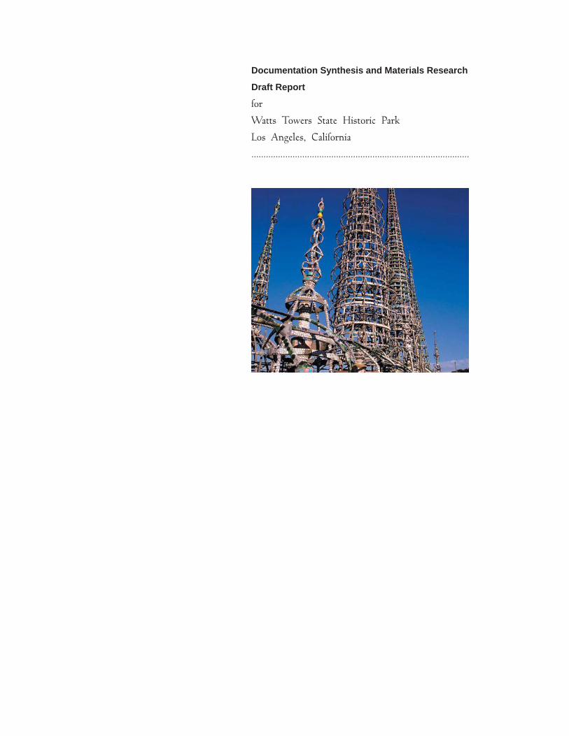
Documentation Synthesis and Materials Research
Draft Report
for
Watts Towers State Historic Park
Los Angeles, California
..........................................................................................

prepared for the State of CaliforniaDepartment of Parks and RecreationSouthern Division Chief ’s OfficeLos Angeles, California
prepared by Architectural Resources GroupArchitects, Planners & ConservatorsSan Francisco, California
March 31, 2006
Watts Towers, Phase II Documentation Synthesis & Materials Research
Architectural Resources Group March 31, 2006
Table of Contents 1
Table of Contents
I. Executive Summary .................................................................................................... 2 II. Introduction................................................................................................................. 4 III. Methodology........................................................................................................... 5
A. Task 1: Synthesis of Documentation ...................................................................... 6 B. Task 2: Materials Testing and Research ................................................................. 8
IV. Results................................................................................................................... 10 A. Task 1: Synthesis of Documentation .................................................................... 10
1. Creating the new model .................................................................................... 10 2. Linking the Data ............................................................................................... 11
B. Task 2: Materials Testing and Research ............................................................... 14 1. Mortars.............................................................................................................. 14 2. Carbonation....................................................................................................... 15 3. Chlorides ........................................................................................................... 16 4. Corrosion Inhibitors .......................................................................................... 17 5. Moisture ............................................................................................................ 20 6. Water Repellents............................................................................................... 20 7. Cracks ............................................................................................................... 21 8. Evaluation of mock-ups. ................................................................................... 22
V. Recommendations..................................................................................................... 23 A. Digital Model Advancements ............................................................................... 23
1. Data Clean-up ................................................................................................... 24 2. Adding new records .......................................................................................... 24 3. Image Tags........................................................................................................ 25
B. Archives ................................................................................................................ 25 C. Computer Technology .......................................................................................... 26 D. Update photo documentation ................................................................................ 27 E. Treatment .............................................................................................................. 27 F. Ongoing Research................................................................................................. 30
Appendices
Appendix A: Photographic Figures
Appendix B: History of Materials Used and Tested
Appendix C: Documentation Guidelines
Appendix D: Materials Analysis
Appendix E: Material Data Sheets
Watts Towers, Phase II Documentation Synthesis & Materials Research
Architectural Resources Group March 31, 2006
2 Executive Summary
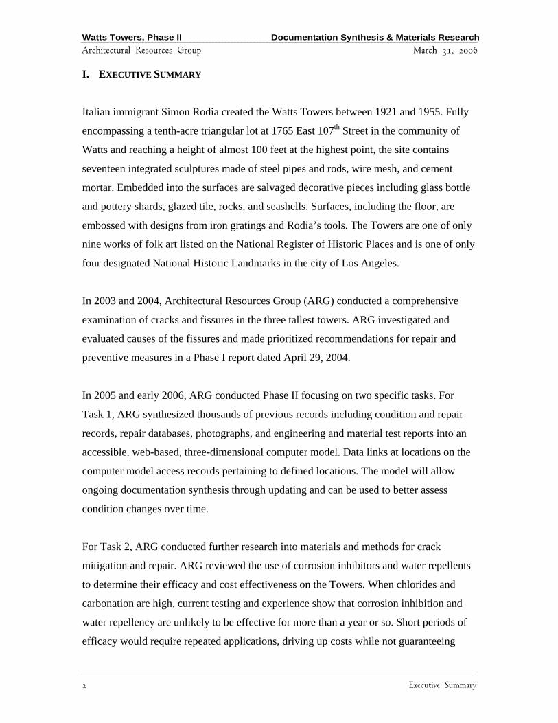
I. EXECUTIVE SUMMARY
Italian immigrant Simon Rodia created the Watts Towers between 1921 and 1955. Fully
encompassing a tenth-acre triangular lot at 1765 East 107th Street in the community of
Watts and reaching a height of almost 100 feet at the highest point, the site contains
seventeen integrated sculptures made of steel pipes and rods, wire mesh, and cement
mortar. Embedded into the surfaces are salvaged decorative pieces including glass bottle
and pottery shards, glazed tile, rocks, and seashells. Surfaces, including the floor, are
embossed with designs from iron gratings and Rodia’s tools. The Towers are one of only
nine works of folk art listed on the National Register of Historic Places and is one of only
four designated National Historic Landmarks in the city of Los Angeles.
In 2003 and 2004, Architectural Resources Group (ARG) conducted a comprehensive
examination of cracks and fissures in the three tallest towers. ARG investigated and
evaluated causes of the fissures and made prioritized recommendations for repair and
preventive measures in a Phase I report dated April 29, 2004.
In 2005 and early 2006, ARG conducted Phase II focusing on two specific tasks. For
Task 1, ARG synthesized thousands of previous records including condition and repair
records, repair databases, photographs, and engineering and material test reports into an
accessible, web-based, three-dimensional computer model. Data links at locations on the
computer model access records pertaining to defined locations. The model will allow
ongoing documentation synthesis through updating and can be used to better assess
condition changes over time.
For Task 2, ARG conducted further research into materials and methods for crack
mitigation and repair. ARG reviewed the use of corrosion inhibitors and water repellents
to determine their efficacy and cost effectiveness on the Towers. When chlorides and
carbonation are high, current testing and experience show that corrosion inhibition and
water repellency are unlikely to be effective for more than a year or so. Short periods of
efficacy would require repeated applications, driving up costs while not guaranteeing

Watts Towers, Phase II Documentation Synthesis & Materials Research
Architectural Resources Group March 31, 2006
Executive Summary 3
adequate protection from water or further corrosion. Furthermore, excessive build-up of
inhibitors and repellents may have a long-term negative effect on multiple materials that
are as yet not known.
The single most highly recommended action is to maintain the site on an on-going basis.
Due to the nature of its construction, crack formation remains inevitable. The variation of
original materials and methods used, plus additional variations in repairs, form a
patchwork of materials that vary in physical properties. Preservation of the Towers will
depend largely on a regularized maintenance program to mitigate cracks as they occur,
thereby reducing water ingress, further crack propagation, and loss of surface material.
Reducing corrosion of the internal steel armature is also desirable; however, to date, no
known “silver bullet” exists that would arrest corrosion in this case. Monitoring,
documenting, and repairing cracks as they occur remains the single most effective
approach for long-term preservation.
A team approach is highly recommended for continuing the preservation of Watts
Towers. Team members should include conservators, conservation scientists, structural
engineers, historians, and community representatives. Architectual Resources Group is
indebted to the City of Los Angeles Historic Site Curator of the Cultural Affairs
Department and the City’s Watts Towers contract Conservator and Engineer for their
generous help and cooperation during both phases of this project.

Watts Towers, Phase II Documentation Synthesis & Materials Research
Architectural Resources Group March 31, 2006
4 Introduction
II. INTRODUCTION
This report presents tasks accomplished in Phase II and follows Architectual Resources
Group’s Phase I “Evaluation and Conservation of Fissures Report” dated April 29, 2005.
During Phase I of the project, ARG assessed the fissures in the three towers and floor. At
the time, background information provided included the 1983 Ehrenkrantz Report and
1983 Conservation Handbook. During Phase II, ARG provided additional documentation.
Recommendations made during Phase I are described in the April 29, 2005 report. In
summary, recommendations included:
• Synthesis of Documentation
• Monitoring and Inspections
• Material Testing and Mock-ups
• Discrete Phase II Repairs
• On-going Maintenance Program
• Material Treatments at Towers
Following peer review, California State Parks revised Phase II of the project to focus on
two tasks. Task 1 was to synthesize existing documentation and Task 2 was to conduct
further materials research specifically for corrosion and crack repairs.
A description of the Watts Towers site with historical context and construction
description can be found in the Phase I report and elsewhere. Conditions of the three
towers and floor are also noted in the Phase I report, as are treatment recommendations.
This report describes further assessment of crack repair materials and methods and
provides further recommendations for treatment in addition to the recommendations
made in the Phase I report.

Watts Towers, Phase II Documentation Synthesis & Materials Research
Architectural Resources Group March 31, 2006
Methodology 5
III. METHODOLOGY
Architectural Resources Group (ARG) worked with a team of experts to accomplish
Phase II Tasks.
David Wessel Architectural Conservator and Principal, Architectual Resources Group
Katharine Untch Objects Conservator and Project Manager, Architectual Resources Group
James Cocks Conservation Technician, Architectual Resources Group
Andrew Lins Consultant, Head of Conservation Department, Philadelphia Museum of Art
George Wheeler Consultant, Research Scientist in the Department of Scientific Research, Metropolitan Museum of Art and Director of Conservation in the Historic Preservation Program, Columbia University.
Jon Asselanis Materials Scientist and Petrographer, Applied Materials & Engineering, Inc
Zuleyma Aguirre Contract Site Conservator, City of Los Angeles
Mel Green Contract Site Structural Engineer, City of Los Angeles
Virginia Kazor Historic Site Curator, Cultural Affairs Department, City of Los Angeles
David Colleen Principal, Planet 9 Studios
Christian Greuel Director of Art & Production, Planet 9 Studios
The ARG team conducted several site visits between April 2005 and March 2006 to meet
with team members, review tasks and outline a plan of work, review and retrieve existing
documentation, conduct a laser scan, conduct materials analysis on site, and take samples
for further laboratory analysis. Details of methodology are described separately for each
task below.

Watts Towers, Phase II Documentation Synthesis & Materials Research
Architectural Resources Group March 31, 2006
6 Methodology
A. Task 1: Synthesis of Documentation
The Task I goal is to gather all relevant historical treatment information into a single
accessible format. To accomplish this task, ARG proposed using a three-dimensional
web-based computer model of the Watts Towers site, to which documentation is linked
via associated locations. For example, the location of cracks and their previous repairs
can be identified on the computer model for accessible condition tracking over time. In
addition to location-specific documentation, documents with more generalized
information, such as inspection reports, condition survey summaries, and historical
correspondence, were linked to the model using a generalized or “no specific location”
feature.
ARG’s contract provided sufficient resources to initiate a basic model, with the
understanding that over time, additional details and documentation can be added. The
intention is for the 3D interface to be a representational facsimile of the architectural
features of the monument, thereby allowing intuitive navigation of the information
residing in the database. ARG’s approach was to provide a substantial foundation upon
which current and future individuals working at the site may easily update the system.
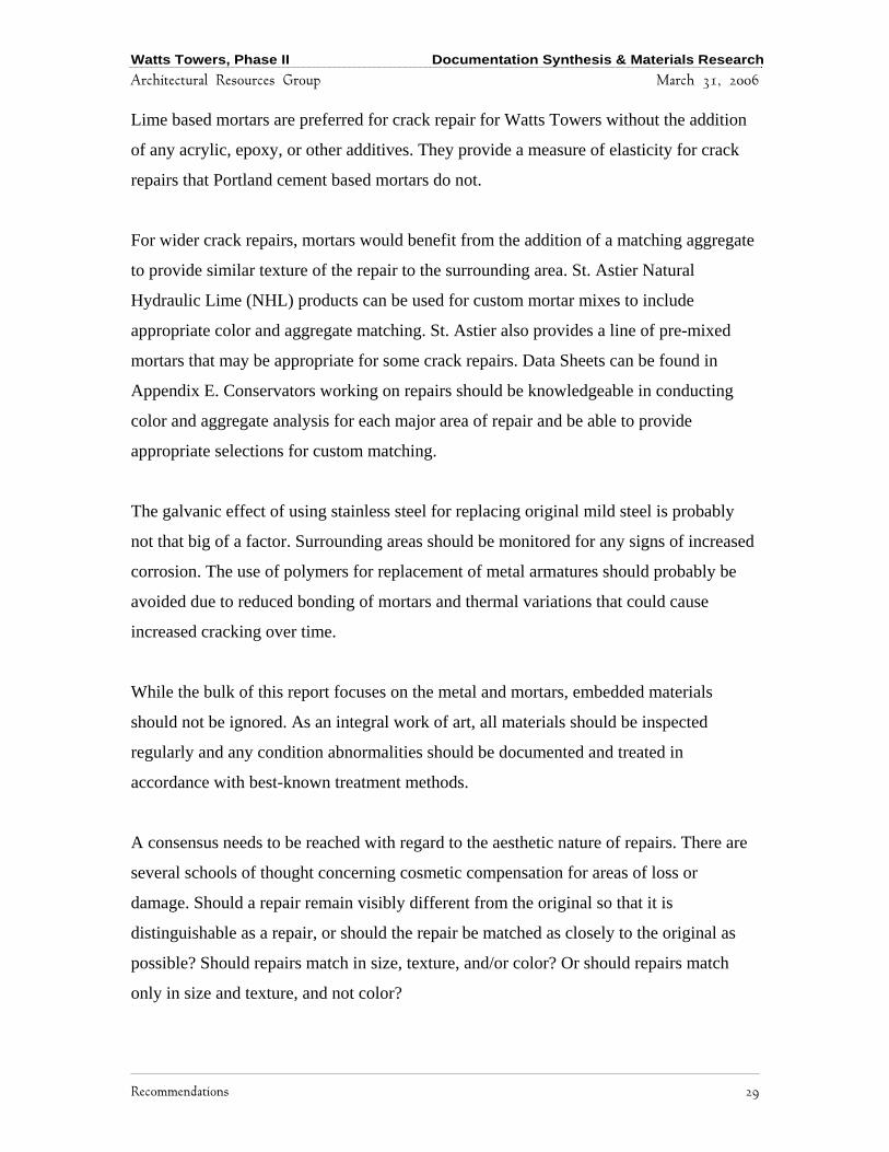
ARG and Ms. Aguirre prioritized documentation used for the first model release. Select
documents were converted into electronic formats and files were organized onto a server.
(See Figure 1). A more detailed description of file organization and nomenclature can be
found in Appendix C. Documentation was synthesized using Microsoft Access™
Database, a readily available software package that allows users to easily update and add
new information. Individual repair records were organized into Access database files, one
for each sculptural feature. An additional Access database file was generated to organize
remaining electronic document files.
Watts Towers, Phase II Documentation Synthesis & Materials Research
Architectural Resources Group March 31, 2006
Methodology 7
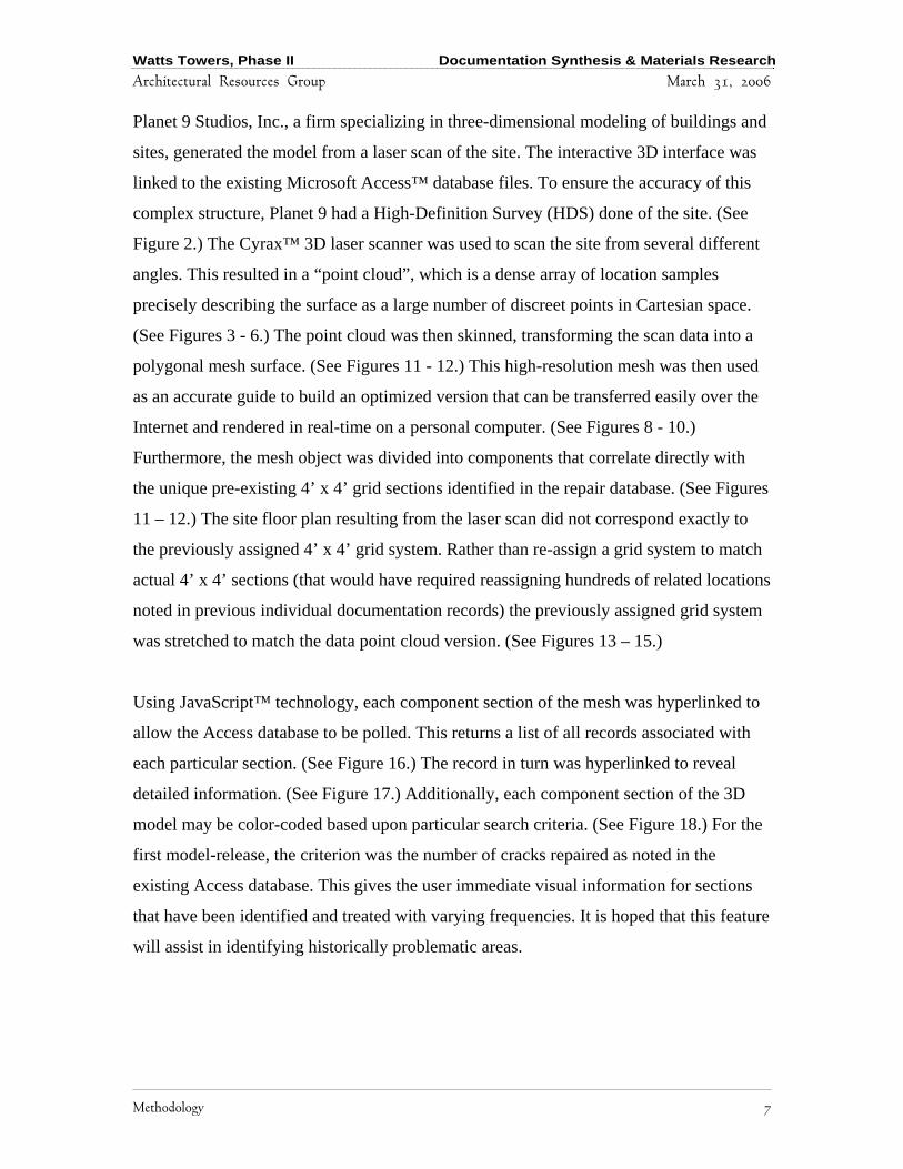
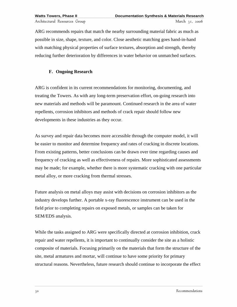
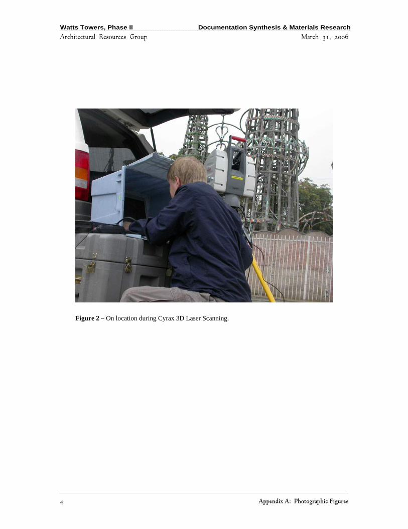
Planet 9 Studios, Inc., a firm specializing in three-dimensional modeling of buildings and
sites, generated the model from a laser scan of the site. The interactive 3D interface was
linked to the existing Microsoft Access™ database files. To ensure the accuracy of this
complex structure, Planet 9 had a High-Definition Survey (HDS) done of the site. (See
Figure 2.) The Cyrax™ 3D laser scanner was used to scan the site from several different
angles. This resulted in a “point cloud”, which is a dense array of location samples
precisely describing the surface as a large number of discreet points in Cartesian space.
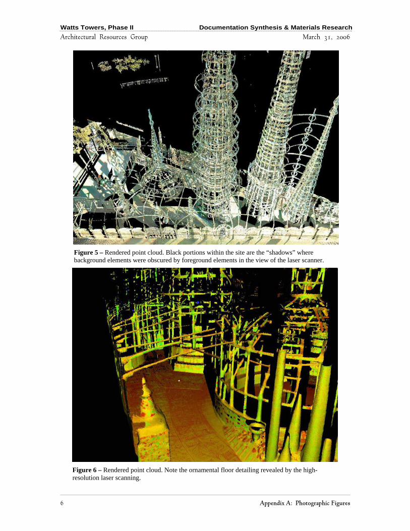
(See Figures 3 - 6.) The point cloud was then skinned, transforming the scan data into a
polygonal mesh surface. (See Figures 11 - 12.) This high-resolution mesh was then used
as an accurate guide to build an optimized version that can be transferred easily over the
Internet and rendered in real-time on a personal computer. (See Figures 8 - 10.)
Furthermore, the mesh object was divided into components that correlate directly with
the unique pre-existing 4’ x 4’ grid sections identified in the repair database. (See Figures
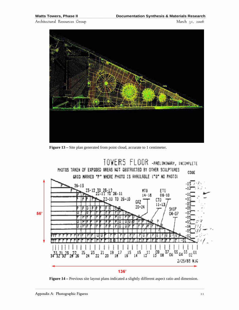
11 – 12.) The site floor plan resulting from the laser scan did not correspond exactly to
the previously assigned 4’ x 4’ grid system. Rather than re-assign a grid system to match
actual 4’ x 4’ sections (that would have required reassigning hundreds of related locations
noted in previous individual documentation records) the previously assigned grid system
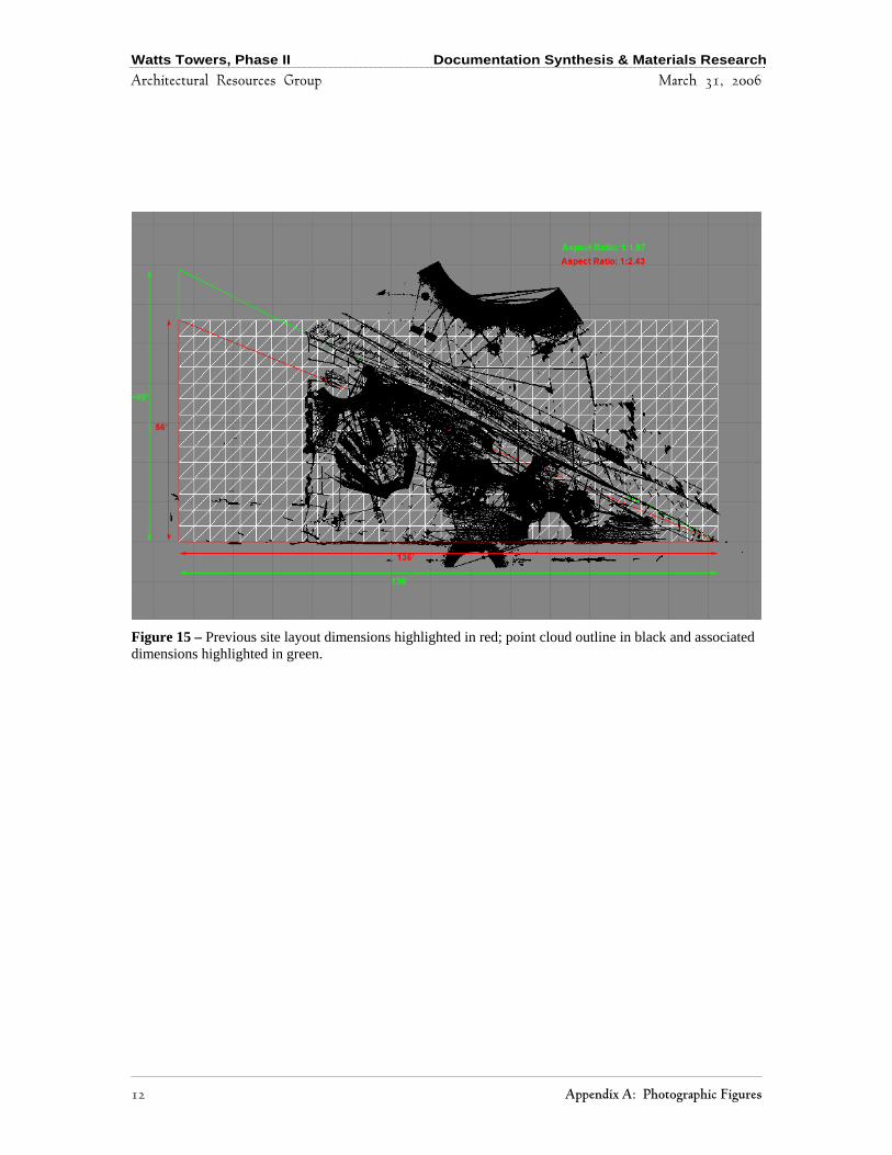
was stretched to match the data point cloud version. (See Figures 13 – 15.)
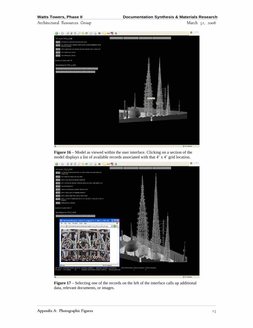
Using JavaScript™ technology, each component section of the mesh was hyperlinked to
allow the Access database to be polled. This returns a list of all records associated with
each particular section. (See Figure 16.) The record in turn was hyperlinked to reveal
detailed information. (See Figure 17.) Additionally, each component section of the 3D
model may be color-coded based upon particular search criteria. (See Figure 18.) For the
first model-release, the criterion was the number of cracks repaired as noted in the
existing Access database. This gives the user immediate visual information for sections
that have been identified and treated with varying frequencies. It is hoped that this feature
will assist in identifying historically problematic areas.

Watts Towers, Phase II Documentation Synthesis & Materials Research
Architectural Resources Group March 31, 2006
8 Methodology
B. Task 2: Materials Testing and Research
The focus for further materials testing and research was to determine the efficacy of
water repellents and corrosion inhibitors. ARG explored whether water repellents and
corrosion inhibitors could stabilize the structure and prove cost effective with respect to
other treatments. In addition to previous tests conducted by ARG during Phase I, ARG
reviewed previous documentation, conducted additional analysis, and consulted jointly
with George Wheeler and Andrew Lins. The consultants reviewed the Phase I report,
previous materials testing that was provided from existing documentation and
recommended further testing conducted during Phase II.
Further tests performed by ARG included additional petrographic and chemical analysis
of selected mortars, levels of carbonation and chlorides, absorption, and infrared
reflectography for moisture content. Appendix D includes individual laboratory
methodologies.
Four cross-sections of Rodia’s original mortar were selected to test for levels of
carbonation and chlorides. Two of these samples were further tested using standard
petrographic analysis and identification of chemical composition of the mortars. As with
all of Watts Towers, samples selected reflect just that: a small sampling of actual
conditions that may be quite varied over the entire site. Test results were compared with
previous tests conducted in 1982 for chloride content.
Surface pH was measured at the site by wetting the surface and applying pH test strips.
Surface chlorides were measured in a similar manner using Mercoquandt chloride
specific test strips and comparing field results with laboratory results. Profiles of pH and
chlorides were conducted on cracks where samples were taken from drilled holes in ¼”
depth increments. The samples were soaked in distilled water and measured with pH test
strips and the Mercoquandt chloride test strips.

Watts Towers, Phase II Documentation Synthesis & Materials Research
Architectural Resources Group March 31, 2006
Methodology 9
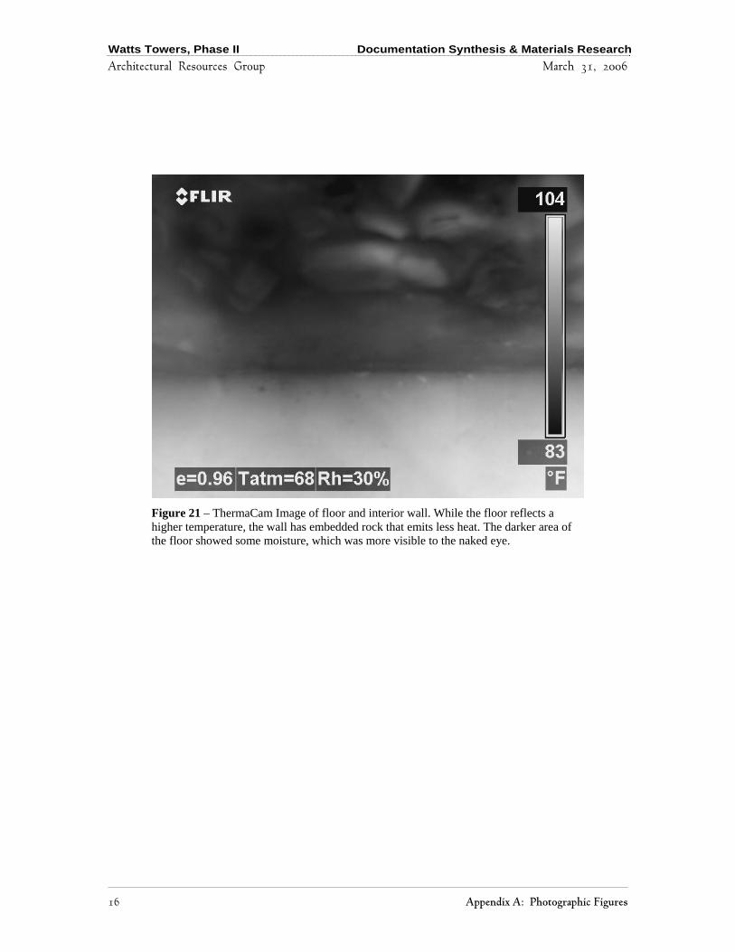
ARG conducted surface absorption tests using RILEM tubes. ARG also tested surface
temperatures with a thermal camera to determine whether differences in moisture
retention could be determined. A ThermaCAM B20HSV from FLIR Systems recorded
thermal images at the site. (See Figures 19 – 21.)
Watts Towers, Phase II Documentation Synthesis & Materials Research
Architectural Resources Group March 31, 2006
10 Results
IV. RESULTS
A. Task 1: Synthesis of Documentation
1. Creating the new model
The 3D computer model was designed and constructed with a specific purpose in mind:
to visualize existing documentation with respect to the condition and conservation history
of the site and to provide an easily accessible tool for organizing and storing future
condition information. Paramount to its success was the optimization of the model for use
on today’s personal computers over an Internet connection. Although complete detailed
surface-texture documentation may be a desirable feature for the future, providing this
feature is still beyond the capacity of present consumer computer-technology, as well as
the scope of this phase of the project. A sufficient level of detail for this purpose could be
obtained with multiple ground-level locations scans taken with the Cyrax laser scanner
with an accuracy level of 1 centimeter.
The process of using 3D laser scanners is analogous to shining a flashlight in absolute
darkness: because of the complexity and surface area of a site, pieces of members
obscured by foregrounding objects can create small shadows in the point cloud. Because
of the intended present-use of this model as a tool for visualizing and analyzing
documentation, these shadows, along with the detailed wire mesh surface of the model,
were approximated with simpler polygonal shapes based on existing documentation to
the highest degree of accuracy possible without implying a false level of precision.
Although by no means does the new model provide complete surface documentation of
all of the elements and conditions of the towers, it serves well to accurately record the
locations of the conditions and repairs. The scans are sufficiently detailed to show many
surfaces of the site elements and general enough to provide context.

Watts Towers, Phase II Documentation Synthesis & Materials Research
Architectural Resources Group March 31, 2006
Results 11
2. Linking the Data
Over the past few decades, extensive documentation has accumulated with regard to the
preservation of the Watts Towers. Several individuals have contributed to the
documentation over time and have followed various systems of cataloguing, many of
which have retained their respective historic naming conventions and organizational
systems. Existing documentation includes historical descriptions, condition surveys,
materials analysis, engineering assessments, repair records, and historic correspondence.
Formats include black and white and color photographic prints, negatives, transparencies
and microfiche, x-ray film, hard copy standard 8 ½” x 11” paper reports, 5” x 7” card
stock as well as electronically scanned bitmap, JPEG, and PDF files, Procite™ and
Microsoft Access™ database files, and Microsoft Word™ document files.
Before ARG’s work, the vast majority of files pertaining to the site remained as hard
copies, including photographs, records, and reports. These documents have been housed
in a 1920s bungalow near the site, eventually overflowing the filing cabinets and stored
in boxes. Electronic files were kept on 5 ¼-inch floppy diskettes, 3 ½-inch floppy disks,
zip disks, and CD-ROM discs. To date, there has been no network access to a server at
the site. Although these storage devices managed to hold many hundreds of digital files,
the system was approaching its limits.
A large-scale photographic effort occurred in the mid-1980s, when the site was
systematically divided into about 1,500 4-foot by 4-foot grids and photographed by
Marvin Rand. The system differs from the other general location naming convention that
identifies each individual member of each sculptural feature. While Rand’s photographs
follow the former system, repair records follow the latter, a more precise location
identification system.
Repair records followed different formatting systems. A system begun in 1979 followed a
repair number using the 4’ x 4’ grid system.
Watts Towers, Phase II Documentation Synthesis & Materials Research
Architectural Resources Group March 31, 2006
12 Results
The individual member within the grid was identified on the repair card, along with
materials used and a picture of the repair. These repairs were entered over time into a
computer database, which changed formats several times. The database was textual only
and contained no photographs.
Many of the early reports, beginning with the 1959 proposal to save the Towers from
demolition, was consolidated in the 1983 Ehrenkrantz Report. Revisions and further
reports were added over the years, and the combination resulted in a binder called the
Conservation Handbook. This binder documents the guidelines, through 1998, for
performing repairs.
ARG realizes its own role as one of the many stewards that over time will contribute to
the preservation of both the site and its records. The digitization, consolidation, and
organization of all files are beyond the present scope of this project. Through establishing
a structure and guidelines, however, it is hoped that all files—past, present, and future—
may eventually be consolidated into one organizational system. For this phase of the
project, ARG synthesized approximately 1,200 of the grid photographs and about 500
repair records and reports, a mere fraction of the total records documenting the site and
its repairs. ARG consulted with Ms. Aguirre and prioritized these initial records
subsequently used to construct the initial file structure and linkages to the model. ARG
provided limited scanning services for documents not yet in electronic formats. With a
basic structure in place, future users may contribute new material to the synthesized
document system.
The Microsoft Access™ database currently used by the City’s conservation team was
minimally altered so as not to disrupt the historic nomenclature and use of the system.
Database and scanned records collected through December 31, 2005 were used to link to
the model. A few records, images, and reports were not identifiable and were left in
electronic file folders marked “unlabelled” until they may be adequately identified.
Watts Towers, Phase II Documentation Synthesis & Materials Research
Architectural Resources Group March 31, 2006
Results 13
Some previous survey reports have valuable condition information with images that were
not yet scanned individually. An example is the 1995 Conditions Survey, Tall Towers
Inspection Report #2, with 31 pages of appended photographs.
Watts Towers, Phase II Documentation Synthesis & Materials Research
Architectural Resources Group March 31, 2006
14 Results
B. Task 2: Materials Testing and Research
A wealth of information, including previous research into original materials used,
proposed treatment methods and materials, and on-going re-evaluations of previous
repairs, has been gathered and presented over the past half century.
A number of materials and techniques have been previously tested and used as repairs to
Watts Towers, including patches and repairs made by Simon Rodia. Subsequent testing
and use of materials over the past fifty-plus years have included various water repellents,
corrosion inhibitors, mortar mixes, polymers (epoxies, urethanes, acrylics, rubbers,
foams), ammoniated, chlorinated and other cleaning agents, and zinc containing
galvanizing compounds. Investigations into passive and active galvanic protection have
also been undertaken in the past and during Phase I of this project. A history of materials
used and tested on the Towers can be found in Appendix B. Although not fully
comprehensive, the references give an idea of the many materials and techniques that
have already been tested and used.
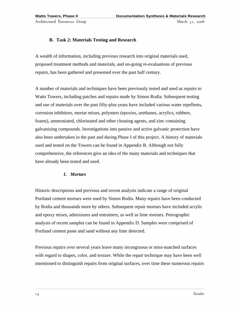
1. Mortars
Historic descriptions and previous and recent analysis indicate a range of original
Portland cement mortars were used by Simon Rodia. Many repairs have been conducted
by Rodia and thousands more by others. Subsequent repair mortars have included acrylic
and epoxy mixes, admixtures and entrainers, as well as lime mortars. Petrographic
analysis of recent samples can be found in Appendix D. Samples were comprised of
Portland cement paste and sand without any lime detected.
Previous repairs over several years leave many incongruous or miss-matched surfaces
with regard to shapes, color, and texture. While the repair technique may have been well
intentioned to distinguish repairs from original surfaces, over time these numerous repairs
Watts Towers, Phase II Documentation Synthesis & Materials Research
Architectural Resources Group March 31, 2006
Results 15
have resulted in a visual confusion of original artist’s intent. In some areas, the repairs
have taken over and are more prevalent than any remaining original surface.
In some cases, repairs were made with a rough, unfinished texture on the surface, while
in other areas repairs are left recessed. Water and moisture are contributors to
deterioration, especially when there is an impediment to its moving freely into and out of
adjacent but different materials. Minute differences in surface texture can cause water or
moisture to pool, thereby accelerating deterioration or causing further cracking in those
areas.
A difference in mortar mixes further exacerbates deterioration. Mortar mixes with
considerably different rates of absorption will impede water migration and evaporation,
thereby affecting deterioration, the early signs of which will probably be in the form of
more cracking. Mortars with admixtures of acrylics, epoxies, or water repellents
generally have lower rates of absorption that will tend to concentrate moisture in adjacent
original, more absorptive mortars. While an epoxy fill may hold up very well over time, it
may cause an increased rate of deterioration or cracking of adjacent original mortar.
Similarly, differences in strengths of repair mortars will impact original mortar mixes.
Crack repairs should be slightly weaker than the surrounding mortar to allow further
movement and cracking in the repair mortar, rather than in the adjacent mortar being
preserved. Repair mortars that are too strong will remain less mobile, causing further
cracking in original mortars when the Towers undergo movement. The only exception to
this is where a stronger mortar mix would be required for structural reasons as
determined by a structural engineer.
2. Carbonation
Watts Towers, Phase II Documentation Synthesis & Materials Research
Architectural Resources Group March 31, 2006
16 Results
Levels of carbonation were also varied. Of the four mortar samples recently tested, three
had non-carbonated pastes with a pH of 13 or greater. One sample was non-carbonated
with a pH of less than 10. Surface pH measurements at lower elevations showed pH of
about 7. The two depth profiles at existing cracks showed a pH of 11 or 12 near the
surface and 7 or 8 from about ½” deep to increasing depths. The varied results indicate
the likelihood that some areas of the Towers have non-carbonated mortars that retain a
magnitude of corrosion protection due to their high pH, while other patches of mortar are
already carbonated. The lower pH at deeper levels along cracks may be indicative of later
repairs possibly even Rodia’s, over older, already carbonated mortars.
3. Chlorides
Removing chlorides is a difficult, if not impossible, undertaking. Cleaning exposed metal
surfaces may improve bonding to repair materials, but any known method of cleaning
would probably not be that effective long term. Air abrasives and mechanical methods
can remove surface corrosion but are also known to trap chlorides under the abraded
surface.
If high levels of chlorides are present, many materials sold commercially for corrosion
inhibition may not be effective. If both chloride levels and carbonation are too high, an
inhibitor may not be sufficiently applied to retard active corrosion in or under a mortar, as
the active chloride corrosion sites will not be pacivated. However, should a lower level of
chlorides be present, some efficacy may exist in using corrosion inhibitors for the short
term, though frequent reapplication would be necessary. It is also of importance to note
where the chlorides are concentrated, whether they be on or near the metal armature,
dispersed throughout the mortar layers, or concentrated on the surface, or in cracks. If
chlorides are bound within the upper layers of the mortar, the penetrating inhibitors may
react there and not be effective in depolarizing chlorides at the steel interface.

Watts Towers, Phase II Documentation Synthesis & Materials Research
Architectural Resources Group March 31, 2006
Results 17
Of the samples tested, the range of chloride levels varied from 0.001% to 0.22% by
weight concrete (mortar). Previous tests for chloride levels by Erlin Hime Associates
circa 1982 indicated chloride levels in mortar samples to range from 0.11 to 0.40 % by
weight cement. Converted roughly to percent weight of concrete, the 1982 samples range
from approximately 0.005 % to 0.014% by weight concrete.
The suggested maximum acid-soluble chloride content for reinforced concrete (to
minimize chloride-induced corrosion) is 0.025% by weight of concrete. (See conversions
in AME report dated February 2, 2006 in Appendix D.) The 1982 samples are below the
suggested maxium chloride level while some of the recent samples have much higher
levels of chloride content.
AME analyzed a profile of chloride content for one sample that showed a spike at 1”
depth, corresponding to an interior elliptical crack around the sample’s metal core about
0.2 inches from the metal.
No consistent correlation was shown between levels of carbonation and levels of
chlorides in any of the samples tested. The sample with the highest chloride content
corresponded with one of the non-carbonated mortar with pH above 13.
Discrete chloride analysis on mortar surfaces at the site all tested negative for chlorides,
as did a previously removed section of corroded steel.
4. Corrosion Inhibitors
a) Galvanic
A discussion of galvanic corrosion inhibitors for use at Watts Towers is described in
ARG’s Phase I report. Active cathodic protection is impractical given the variety of mild
steel used for internal armatures and their incongruous joinery.
Watts Towers, Phase II Documentation Synthesis & Materials Research
Architectural Resources Group March 31, 2006
18 Results
A commercially available passive system with custom sized sacrificial anodes could be
inserted into repairs. A patchwork of uneven sacrificial anodes in juxtaposition to a non-
contiguous metal armature may affect neighboring areas, causing increased galvanic
corrosion of original metals outside the area to be pacified. This is often seen in the
concrete industry as corrosion “rings” or “shadows” where a passive anode protects about
3 feet of rebar, but causes accelerated corrosion in a “ring” or “shadow” just beyond the
individual anode’s effective area.
When using such a system, multiple anodes are utilized and the spacing between each
anode is calculated to prevent this type of shadowing effect. In the case of the Watts
Towers, it would be difficult to internally insert a sacrificial anode at pre-set distances to
avoid this shadowing effect.
b) Chemical
Chemical corrosion inhibitors generally fall into one of three basic categories:
fluorophosphates, nitrates/nitrites and alkanolamines. The fluorophosphates are generally
less successful for this type of application. The nitrites and alkanolamines, generally
work by raising the pH. They are usually pooled on the surface of the mortar or concrete
and allowed to penetrate through to the metal reinforcement. This is fairly old technology
and has been often used in boilers or to stabilize steam converters. Calcium nitrites may
be more effective with new materials, but its efficacy on Watts Towers will depend on
levels of carbonation or chlorides inside the mortar. When levels are low, it can be
effective in bringing back an oxyhydroxide surface on the metal.
Sika Ferroguard 903 is an alkanolamine product designed for surface application. It has
been tested to penetrate to a depth of 3-inches, which is adequate for most areas of the
Towers, as the average depth range of mortars is ½” to 2”. Sika Ferroguard 903 is
effective in low to high pH so should not be affected by the varying levels of carbonation
found in the samples. The manufacturer recommends that the product be allowed to sit on
the surface and penetrate for at least 24 hours.
Watts Towers, Phase II Documentation Synthesis & Materials Research
Architectural Resources Group March 31, 2006
Results 19
If a surface water repellent is to be applied, then the surface should first be rinsed well to
remove a surfactant from the Sika Ferroguard 903 before application of a water repellent.
According to the manufacturer, the chloride content limitation for the Ferroguard 903
effectiveness is between 6 to 12 lbs of chlorides per cubic yard of concrete. This converts
to approximately 0.15 % to 0.30 % weight of concrete. Levels of chlorides appear to be
sufficiently low to provide some efficacy of the product. However, treating one section
without treating adjacent sections of metal may not prove to be that effective overall.
Effective penetration is likely not to be uniform over the entire surface. Previous water
repellents and mortar admixtures with low absorption used on the site will likely inhibit
penetration. With the variety of mortar mixes, some with acrylics, epoxies or other
admixtures, application of penetrating corrosion inhibitors may not result in the inhibitor
reaching the metal armature in sufficient quantities to effect inhibition of the metal where
it is needed.
The efficacy of penetrating inhibitors may taper off over time. While there may be some
temporary increase of pH during the repair campaign, the long-term effectiveness of
penetrating inhibitors has yet to be proven. There is no data to show that the benefits
from inhibitors could last more than a few years. The Ferroguard alkanolamines have
been on the market a relatively short time and as yet have not been field tested for longer
term effectiveness for applications on already deteriorated metals in mortar matrixes such
as on the Watts Towers.
There is also a level of unpredictability with the effect of repeated reapplications of
penetrating inhibitors. Retreating every couple years with calcium nitirite, for example,
has not been shown to be effective. While application of calcium nitrates should not
impede water repellants, the effects of an excess of calcium nitrite salts from successive
reapplications on mortars and other embedded surface materials is yet unknown.

Watts Towers, Phase II Documentation Synthesis & Materials Research
Architectural Resources Group March 31, 2006
20 Results
Using inhibitors as admixtures to new mortars has been shown to have benefit in the
concrete industry for new rebar, but this does not necessarily apply for metals that are
already corroded such as at Watts Towers.
5. Moisture
Absorption tests showed a wide range of absorption rates from zero to over two
ml/minute. It was difficult to conduct surface absorption tests due to the variety of
surface textures and existence of micro-cracks. Selecting a sufficiently smooth surface
without existing cracks or previous repairs proved challenging. Some areas noted as
Rodia’s mortars had almost no absorbency and appeared to have been treated with a
water repellent at some time in the past. Some repair mortars also had low absorption.
Due to the variation in materials, thicknesses of metal and mortars, and embedded
materials, it was difficult to ascertain moisture retention patterns using an infrared
thermal camera. Sample images are described in Appendix A, Figures 14 through 16.
Condensate may also be affecting carbonation and corrosion. The atmosphere is fairly
acidic in Los Angeles and at times may have been even more acidic from increased smog
levels. Acidic condensate may contribute to lowering mortar pH. Condensate may also
bring chlorides and other salts to the surface and concentrated into cracks.
6. Water Repellents
Factors affecting water repellency include surface morphology that allow water to pool in
small crevices and interfaces with imbedded materials, cracks that will retain water, and
materials that impede water evaporation, including embedded materials and repair
materials that have lower porosity or absorbency than the original mortars used.

Watts Towers, Phase II Documentation Synthesis & Materials Research
Architectural Resources Group March 31, 2006
Results 21
Application of several commercial products to alkali substrates will result in some water
repellency, but they may have to be reapplied every year or so, as they will degrade.
Water repellents for reducing the penetration of chloride containing water were
investigated in 1982 on behalf of the Ehrenkrantz Group. Included in the study were
Hydrozo Clear 30, Hydrozo Clear Double 7, Hydrozo Clear 15, Chemstop Heavy Duty,
Chemstop for Concrete, Wacker Silicon and Chemtrete BSM 40. Of the materials tested,
Chemtrete BSM 40 was recommended as having the greatest effect on chloride
screening.
7. Cracks
Crack development on the Towers remains inevitable given the nature of materials used
and construction techniques. Causes of cracking may include Tower movement due to
seismic activity, ground settling, wind, daily thermal fluctuations, differences in original
mortar mixes, differences in repair mortars, surface texture, mass ratios of metal to
mortar in different areas, salt crystallization or deterioration of mortars from salts,
corrosion of metals, and/or corrosion jacking. Some of these causes may be relatively
minor and, in some cases, it may be difficult to determine precise associations between a
crack and its cause. Crack prevention is unlikely ever to be successful. On the other hand,
crack mitigation is possible for some causes and can be altered somewhat by treatment
methods such as selection of appropriate repair mortars.
Regardless of the cause of cracking, on-going monitoring and maintenance remains the
best course of action to reduce egress of water to the metal core and reducing the
potential for further corrosion and separation of mortar layers. Specific structural cracks
should always be addressed in consultation with a structural engineer and structural
repairs designed accordingly.
Watts Towers, Phase II Documentation Synthesis & Materials Research
Architectural Resources Group March 31, 2006
22 Results
8. Evaluation of mock-ups.
In November 2004, ARG conducted mock-ups of crack repairs. The areas tested were re-
examined in March 2006.
In four cases out of five, Jahn mortars showed signs of cracking where one or another
edge of the crack repair had separated from the original edge by approximately 1/64” to
1/32”. It is likely that the cracks were due to shrinkage of the mortars while curing and
lack of adhesion between the Jahn mortar and existing mortar to be repaired. The Jahn
mortars are known to be a little “fussy” and require strict adherence to curing conditions,
keeping them moist, but not overly wet, over several days to cure properly. The
manufacturer recommends specific training for use of their products and does not
recommend using any additives or variations such as pigments in their mortars; however,
adding dry pigments is a common practice in the field.
In summary, crack repairs as outlined in Phase I should be effective. Lime based mortars
without the addition of acrylics or epoxies is preferred. The use of water repellents and
corrosion inhibitors may not prove sufficiently effective to warrant their cost. Water
repellents may induce water channeling into existing cracks and alter surface appearance
somewhat. The use of surface applied water repellents may also inhibit surface
penetrating corrosion inhibitors should those be of use in the future.

Watts Towers, Phase II Documentation Synthesis & Materials Research
Architectural Resources Group March 31, 2006
Recommendations 23
V. RECOMMENDATIONS
A. Digital Model Advancements
As computer technology advances and further resources become available, enhancements
to the computer model can be achieved. While it is tempting to propel a computer model
to a full-blown technological wonder, a more pragmatic and economical approach in
keeping with the goals of the proposed preservation program is outlined here in order of
priority.
1. Further articulate locations on the model to include individual member names, for
example “exterior column” or “intermediate band,” using the existing labeling
system that has been used for site records. This will allow for more precise
locations for data hyperlinks, thereby enhancing assessment capabilities of
previous condition records. It will also allow for easier recording for locations of
future tests and repairs, a very time consuming process for those not as familiar
with specific locations within the site.
2. Document cracks visually on the model so that when the computer cursor passes
over a section, the identification of the crack with its associated properties in
particular noted dimensions appear with associated dates. This will give a better
indication of the change in condition of cracks over time.
3. Display a rendered color-surface on the model based on photographic campaigns
to identify additional surface features and conditions. The rendered surface will
serve as a photographic document of condition at a unique point in time that can
later be compared with future rendered scans.
4. Generate higher resolution models of the site to allow for more detailed recording
of surfaces and locations.

Watts Towers, Phase II Documentation Synthesis & Materials Research
Architectural Resources Group March 31, 2006
24 Recommendations
5. Integrate high-resolution digital photography with the computer model to provide
a more detailed baseline for monitoring condition changes over time. Future 3D
snapshots of the site may provide greater levels of precision.
6. Explore additional uses of the model as technology permits. The current model
and point cloud, for instance, may be compared with a future 3D laser scan to see
if any features have experienced shifting or displacement. Additionally, point
clouds may be used to generate models to be used for engineering studies of the
towers.
1. Data Clean-up
Files contained in folders marked “unlabelled” need to be correctly identified and labeled
according to the established nomenclature. Then these files can be linked to the model.
Single records of multiple page reports containing individual images or analytical tests
related to a specific location on the site can be exploded and each image or analysis saved
as a separate file in accordance with the established nomenclature. These files can then be
linked to the model.
The Microsoft Access™ Database may be updated and refined for ease of use. As future
technologies become available, data can be converted. Maintaining the data in a format
that is readily available to users is highly recommended. Established database vendors are
preferable.
2. Adding new records
ARG prioritized historic records for inclusion with the first model release. Additional
records to add include approximately 50 boxes of repair record photographs attached to
5” x 7” index cards that need to be individually scanned and labeled according to
established nomenclature.

Watts Towers, Phase II Documentation Synthesis & Materials Research
Architectural Resources Group March 31, 2006
Recommendations 25
Existing reports, correspondence, repair records, photographic records, high-resolution
scans of X-rays, and any other documents that pertain to the site’s condition or
preservation may also be added.
Future surveys, assessments, studies, and treatment campaigns should all be added to the
existing system of record keeping.
It will be important to utilize the established nomenclature for site locations as well as
nomenclature for labeling electronic documents. Nomenclature guidelines can be found
in Appendix C.
3. Image Tags
Image tags should be applied to each image and document of the files, establishing
copyright and authorship. These tags assist in defining the source of the document when
shared over the Internet.
B. Archives
Preservation of existing records is paramount as is their on-going accessibility. Scanning
documents to convert them to electronic formats and making them available through the
Internet may provide increased accessibility but does not address the preservation of
important original documentation. Electronic conversions do not replace the level of
photographic resolution or the details required by conservators, scientists and engineers
in addressing the overall site preservation. Even after reviewing electronic
documentation, individuals will still need to reference original documentation materials
for details that can be helpful in determining rates of deterioration and future treatment
designs.
During site visits, it became clear that records kept at the site would benefit from the care
of professional archivists and archive conservators.
Watts Towers, Phase II Documentation Synthesis & Materials Research
Architectural Resources Group March 31, 2006
26 Recommendations
Furthermore, the location of paper-based records at the site does not provide the level of
security or environmental conditions conducive to their warranted preservation. ARG
strongly recommends that a more appropriate repository, such as a city or state library or
archive, be identified where the materials can be appropriately housed, catalogued, and
cared for.
As state property, any physical parts from the site should be collected from various
individuals and locations and retained in one clean, secure location. Removed parts may
include sections that fell off, were removed for analysis, or were removed during repair.
All parts should be clearly labeled and catalogued with their original location on the site
noted and purpose for removal. The catalogue should use Microsoft Access™ database
and follow nomenclature guidelines so that it can be linked to the model.
C. Computer Technology
An improvement to computer technology at the site is highly recommended. The City’s
conservation team as yet has no site access to a networked server, and the computers have
limited capacity to deal with the current volume of records. Still used at the site on a daily
basis is a combination of: 3 ¼” and 5 ½” floppy disks, zip disks and CD-ROMs. Data on
these various media formats needs to be converted to a server that is maintained by
professional information technicians and backed up on a regular basis. Additionally, the
computer equipment itself is outdated and should be updated.
Using a laptop in the field with wireless access to a data entry screen can further enhance
accurate and up-to-date documentation during on-going repairs. New data can be entered
directly into the system, or into a secondary working system with periodic updates to the
public website.

Watts Towers, Phase II Documentation Synthesis & Materials Research
Architectural Resources Group March 31, 2006
Recommendations 27
D. Update photo documentation
During the next treatment campaign, when scaffolding is erected, new 4-foot by 4-foot
transparencies should be taken of the towers for comparison with the photos taken by
Marvin Rand from 1987-1992. These images will provide a 15-20 year span of valuable
visual information for condition comparisons.
Future photography should include in-frame measurement scale, grey scale and color
scale. This will assist image wrapping and future analyses quantifying the exact identity
of surface colors and to quantify future color changes, such as fading.
High-resolution photography may also be applied to the model for condition
documentation. Images may also be applied to the 3D computer model as a rendered
surface. Although the wrapping would not be 100% accurate with regard to alignment, it
should be close enough for comparison purposes and for monitoring cracks and other
conditions.
E. Treatment
The Towers were constructed with a variety of materials and methods. Inconsistencies in
the physical properties of original materials plus addition variations of repair materials
make the site a patchwork of physical characteristics. As such, conservation approaches
must take into consideration that treatments cannot be designed as if the site consisted of
a single set of cohesive materials.
The nature of the materials and methods used to construct Watts Towers dictate the need
for on-going maintenance. The history of conditions demonstrates that cracking is likely
to continue. Unfortunately, no known “silver bullet” exists that will arrest all corrosion
and cracking. Mitigating cracks and their propagation will be the most beneficial
approach for long-term preservation of the Towers.
Watts Towers, Phase II Documentation Synthesis & Materials Research
Architectural Resources Group March 31, 2006
28 Recommendations
Inspections should continue on an annual basis. Repairs at lower levels should be
continued on an annual basis while upper levels requiring scaffolding may be repaired on
a five to ten year cycle, leaving the Towers free of scaffolding to be enjoyed for
significant periods of time. Regular maintenance is the highest priority, higher even than
exactly what repair materials are used as these may change as technology changes over
the years. Regardless of the exact repair materials used, cracks should be repaired a soon
as possible. Leaving cracks exposed to the elements greatly increases the risk of
accelerating corrosion of the interior metal pieces.
A cyclical maintenance plan will help reduce costs over the long-term by mitigating
conditions in their early phases. Gaps in regular maintenance will result in more
extensive and hence more costly conservation treatments.
A major concern in prescribing materials to be used as fillers and for repairs is the
compatibility of materials with regard to strength, density, porosity, texture, as well as
visual integration. Repair materials that have large differences in water absorption, can
impede evaporation and trap water in the repair material, original mortar, or the interface
between the two components. Trapped water may allow for continued reactions,
including migration of salts and galvanic corrosion of the armature. Epoxy fills, acrylic
admixtures and Portland based cements have lower porosities than the Rodia mortars and
may accelerate deterioration by chemical reactions in the presence of water in the original
mortar or at interfaces.
Methods for crack repair are outlined in the Phase I report. In addition to previous
recommendations, ARG recommends that the cause of each crack be determined (as
much as possible) and recorded in the inspection and treatment records. Repair methods
for cracks caused by different aspects (corrosion jacking vs. shrinkage of mortars for
example) may require different treatments in the future. This information will aide in
future assessments of repair materials and methods for each type of cracking.
Watts Towers, Phase II Documentation Synthesis & Materials Research
Architectural Resources Group March 31, 2006
Recommendations 29
Lime based mortars are preferred for crack repair for Watts Towers without the addition
of any acrylic, epoxy, or other additives. They provide a measure of elasticity for crack
repairs that Portland cement based mortars do not.
For wider crack repairs, mortars would benefit from the addition of a matching aggregate
to provide similar texture of the repair to the surrounding area. St. Astier Natural
Hydraulic Lime (NHL) products can be used for custom mortar mixes to include
appropriate color and aggregate matching. St. Astier also provides a line of pre-mixed
mortars that may be appropriate for some crack repairs. Data Sheets can be found in
Appendix E. Conservators working on repairs should be knowledgeable in conducting
color and aggregate analysis for each major area of repair and be able to provide
appropriate selections for custom matching.
The galvanic effect of using stainless steel for replacing original mild steel is probably
not that big of a factor. Surrounding areas should be monitored for any signs of increased
corrosion. The use of polymers for replacement of metal armatures should probably be
avoided due to reduced bonding of mortars and thermal variations that could cause
increased cracking over time.
While the bulk of this report focuses on the metal and mortars, embedded materials
should not be ignored. As an integral work of art, all materials should be inspected
regularly and any condition abnormalities should be documented and treated in
accordance with best-known treatment methods.
A consensus needs to be reached with regard to the aesthetic nature of repairs. There are
several schools of thought concerning cosmetic compensation for areas of loss or
damage. Should a repair remain visibly different from the original so that it is
distinguishable as a repair, or should the repair be matched as closely to the original as
possible? Should repairs match in size, texture, and/or color? Or should repairs match
only in size and texture, and not color?
Watts Towers, Phase II Documentation Synthesis & Materials Research
Architectural Resources Group March 31, 2006
30 Recommendations
ARG recommends repairs that match the nearby surrounding material fabric as much as
possible in size, shape, texture, and color. Close aesthetic matching goes hand-in-hand
with matching physical properties of surface textures, absorption and strength, thereby
reducing further deterioration by differences in water behavior on unmatched surfaces.
F. Ongoing Research
ARG is confident in its current recommendations for monitoring, documenting, and
treating the Towers. As with any long-term preservation effort, on-going research into
new materials and methods will be paramount. Continued research in the area of water
repellents, corrosion inhibitors and methods of crack repair should follow new
developments in these industries as they occur.
As survey and repair data becomes more accessible through the computer model, it will
be easier to monitor and determine frequency and rates of cracking in discrete locations.
From existing patterns, better conclusions can be drawn over time regarding causes and
frequency of cracking as well as effectiveness of repairs. More sophisticated assessments
may be made; for example, whether there is more systematic cracking with one particular
metal alloy, or more cracking from thermal stresses.
Future analysis on metal alloys may assist with decisions on corrosion inhibitors as the
industry develops further. A portable x-ray fluorescence instrument can be used in the
field prior to completing repairs on exposed metals, or samples can be taken for
SEM/EDS analysis.
While the tasks assigned to ARG were specifically directed at corrosion inhibition, crack
repair and water repellents, it is important to continually consider the site as a holistic
composite of materials. Focusing primarily on the materials that form the structure of the
site, metal armatures and mortar, will continue to have some priority for primary
structural reasons. Nevertheless, future research should continue to incorporate the effect

Watts Towers, Phase II Documentation Synthesis & Materials Research
Architectural Resources Group March 31, 2006
Recommendations 31
of treatment materials and methods on embedded surface materials such as rocks, shell,
ceramic, and glass.

Watts Towers, Phase II Documentation Synthesis & Materials Research
Architectural Resources Group March 31, 2006

Watts Towers, Phase II Documentation Synthesis & Materials Research
Architectural Resources Group March 31, 2006
Appendix A: Photographic Figures 1
Appendix A:
Photographic Figures

Watts Towers, Phase II Documentation Synthesis & Materials Research
Architectural Resources Group March 31, 2006
2 Appendix A: Photographic Figures
Watts Towers, Phase II Documentation Synthesis & Materials Research
Architectural Resources Group March 31, 2006
Appendix A: Photographic Figures 3
Figure 1 – File organization of existing documentation.
Watts Towers, Phase II Documentation Synthesis & Materials Research
Architectural Resources Group March 31, 2006
4 Appendix A: Photographic Figures
Figure 2 – On location during Cyrax 3D Laser Scanning.

Watts Towers, Phase II Documentation Synthesis & Materials Research
Architectural Resources Group March 31, 2006
Appendix A: Photographic Figures 5
Figure 3 - View of Point Cloud generated by laser scanning. The points are accurate to 1 centimeter.
Figure 4 – Detail of point cloud.
Watts Towers, Phase II Documentation Synthesis & Materials Research
Architectural Resources Group March 31, 2006
6 Appendix A: Photographic Figures
Figure 5 – Rendered point cloud. Black portions within the site are the “shadows” where background elements were obscured by foreground elements in the view of the laser scanner.
Figure 6 – Rendered point cloud. Note the ornamental floor detailing revealed by the high-resolution laser scanning.
Watts Towers, Phase II Documentation Synthesis & Materials Research
Architectural Resources Group March 31, 2006
Appendix A: Photographic Figures 7
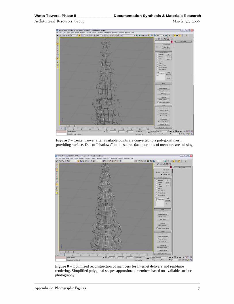
Figure 7 – Center Tower after available points are converted to a polygonal mesh, providing surface. Due to “shadows” in the source data, portions of members are missing.
Figure 8 – Optimized reconstruction of members for Internet delivery and real-time rendering. Simplified polygonal shapes approximate members based on available surface photography.
Watts Towers, Phase II Documentation Synthesis & Materials Research
Architectural Resources Group March 31, 2006
8 Appendix A: Photographic Figures
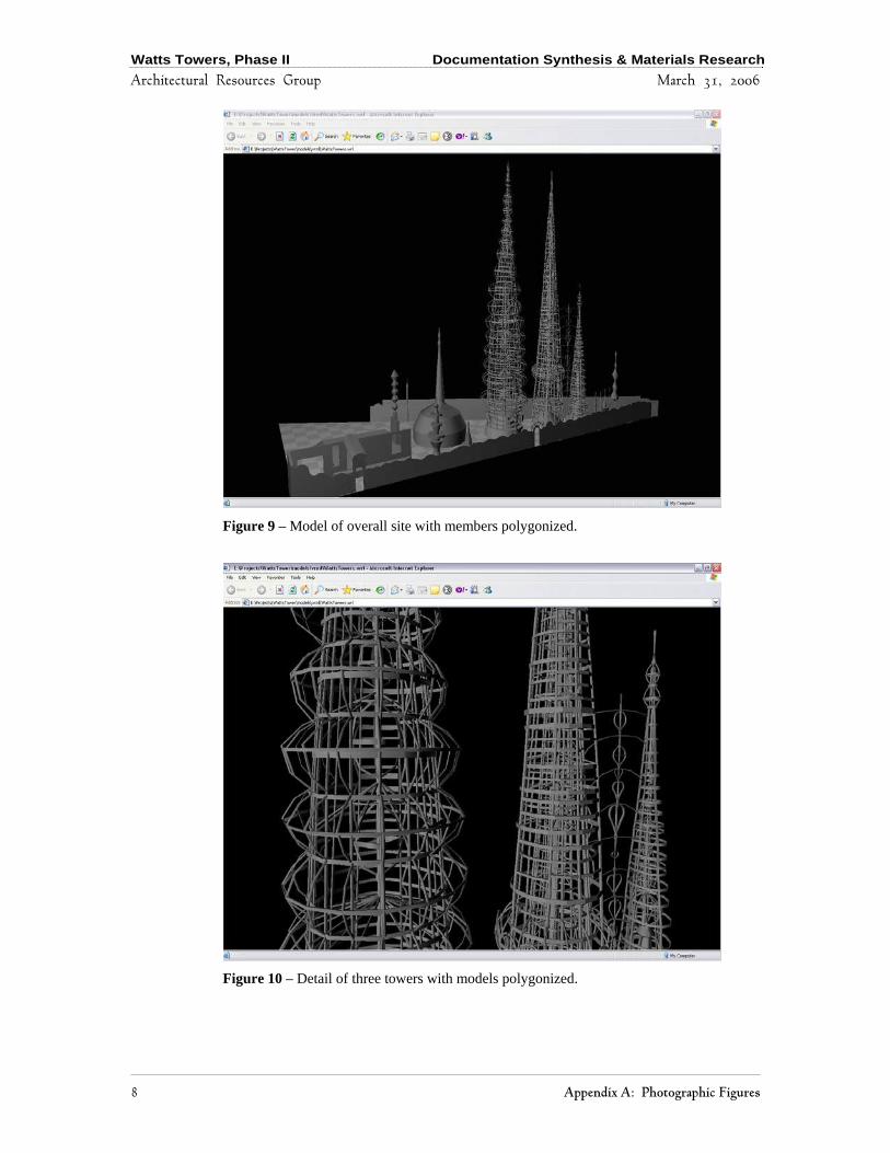
Figure 9 – Model of overall site with members polygonized.
Figure 10 – Detail of three towers with models polygonized.

Watts Towers, Phase II Documentation Synthesis & Materials Research
Architectural Resources Group March 31, 2006
Appendix A: Photographic Figures 9
Figure 11 – Previous 4-foot by 4-foot grid system used to map each section of the towers. This grid was used as the base system for mapping areas directly to the computer model.
Watts Towers, Phase II Documentation Synthesis & Materials Research
Architectural Resources Group March 31, 2006
10 Appendix A: Photographic Figures
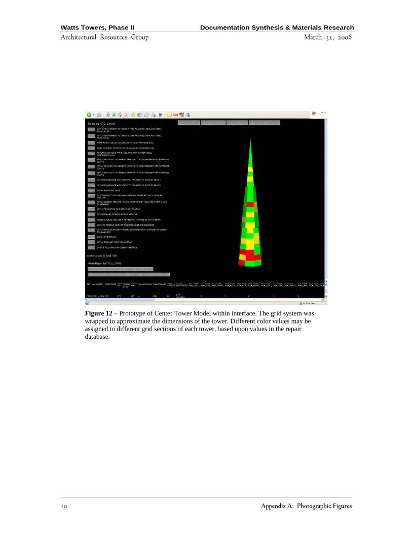
Figure 12 – Prototype of Center Tower Model within interface. The grid system was wrapped to approximate the dimensions of the tower. Different color values may be assigned to different grid sections of each tower, based upon values in the repair database.
Watts Towers, Phase II Documentation Synthesis & Materials Research
Architectural Resources Group March 31, 2006
Appendix A: Photographic Figures 11
Figure 13 – Site plan generated from point cloud, accurate to 1 centimeter.
Figure 14 – Previous site layout plans indicated a slightly different aspect ratio and dimension.
Watts Towers, Phase II Documentation Synthesis & Materials Research
Architectural Resources Group March 31, 2006
12 Appendix A: Photographic Figures
Figure 15 – Previous site layout dimensions highlighted in red; point cloud outline in black and associated dimensions highlighted in green.
Watts Towers, Phase II Documentation Synthesis & Materials Research
Architectural Resources Group March 31, 2006
Appendix A: Photographic Figures 13
Figure 16 – Model as viewed within the user interface. Clicking on a section of the model displays a list of available records associated with that 4’ x 4’ grid location.
Figure 17 – Selecting one of the records on the left of the interface calls up additional data, relevant documents, or images.

Watts Towers, Phase II Documentation Synthesis & Materials Research
Architectural Resources Group March 31, 2006
14 Appendix A: Photographic Figures
Figure 18 – The model can be color-coded based upon particular values in the database, such as cumulative number of cracks repaired per section.

Watts Towers, Phase II Documentation Synthesis & Materials Research
Architectural Resources Group March 31, 2006
Appendix A: Photographic Figures 15
Figure 19 – ThermaCam Image. Dark areas show higher temperatures due to sun on surface. Light areas are in shadow and are cooler.
Figure 20 – ThermaCam Image at Ship of Marco Polo. Light areas are higher temperature. Glazed tiles reflect more energy than surrounding cement mortars. Tiles in foreground have cooler surfaces. Variations in mortar color are largely due to thermal variations from sunlight and shadows.
Watts Towers, Phase II Documentation Synthesis & Materials Research
Architectural Resources Group March 31, 2006
16 Appendix A: Photographic Figures
Figure 21 – ThermaCam Image of floor and interior wall. While the floor reflects a higher temperature, the wall has embedded rock that emits less heat. The darker area of the floor showed some moisture, which was more visible to the naked eye.
Watts Towers, Phase II Documentation Synthesis & Materials Research
Architectural Resources Group March 31, 2006
Appendix B: History of Materials Used and Tested 1
Appendix B: History of Materials Used and Tested

Watts Towers, Phase II Documentation Synthesis & Materials Research
Architectural Resources Group March 31, 2006
2 Appendix B: History of Materials Used and Tested
Watts Towers, Phase II Documentation Synthesis & Materials Research
Architectural Resources Group March 31, 2006
Appendix B: History of Materials Used and Tested 3
Appendix B History of Materials Used at Watts Towers
Purpose This summary outlines previous and recent materials used on the Watts Towers. While not comprehensive, the information provides an overview of the variety of materials tested and used prior to the current contract with Architectual Resources Group. 1) Iron Original: Found pieces of iron alloys (including various grades of steel) were used originally, including pieces from the nearby railroad and metal scrap yards. Elements included angle, rods, pipes, channels or railroad ties, generally lap joined and wrapped with copper or iron wire. No bolts, screws or welds have been found in the original work. Repairs: Repair specifications from circa 1979 through present recommend replacing corroded iron elements with stainless steel. Corroded elements not deemed for replacement have had loose mortar chiseled away, sections sawed off, stainless steel replacement, spliced or wrapped as original; or old iron sandblasted, cleaned with compressed air, application of rust inhibitor (ZRC Cold Galvanizing Compound) and application of new patch mortar. Some of the pipes retained water. (1981). Nylon or Teflon rod to replace iron section. (1990’s?) 2) Mortars Original: Original mortars varied in composition, color and texture. Most commonly used was a grey colored sand-lime-cement mortar with very coarse aggregate. Green, yellow, read and blue pigments were also used. Mortar depth ranges from ¼ inch to 1½ inches with typical thickness at ½ inch. Analysis: Original mortars tested 1959 (Smith Emery), 1979, 1983 (Eherenkrantz) and petrographic analysis 1983. Aggregate: cement 21/4 – 3:1. Aggregate: crushed granite or poorly rounded natural sand. Mortars are Portland cement based, strength similar to Type M (no lime) though it is possible lime may also have been used in small quantities. Air-entrained mortars found at 67 – 75 ft high. May have been later patches. Chlorides present, no correlation with height, though highest values were at lower and upper levels. May have used unwashed sand in some original mortar mixes.
Watts Towers, Phase II Documentation Synthesis & Materials Research
Architectural Resources Group March 31, 2006
4 Appendix B: History of Materials Used and Tested
Repairs: Repair mortars indicated in circa 1979 specifications is to mix 1:3 cement:sand with 90% water 10% Acryl 60. 1983 1:3 cement:quartz/calcite sand. Recommends no more than 10% Acryl 60 to allow effectiveness of alkyl-alkoxy-silane. Sikadur Hi-Mod 2 part epoxy bonding agent on bare armature before patching mortar.1 3) Surface Decorations Original: A variety of materials are embedded into the mortars.
a) Glass b) Ceramic (glazed and unglazed) c) Shell d) Pebbles, rocks, clinker and stone e) Cast stone
Repairs: Opticon UV for glass-to-glass bonds.2 Brasso or Noxon to clean glazed tiles.3 4) Coatings
a) Corrosion Inhibitors ZRC Cold Galvanizing Compound, a zinc primer in epoxy ester.4 Duro Naval Jelly (for corrosion removal)
b) Water Repellents Alyl-alkoxy-silanes tested, including Wacker H, Cydrozo Clear, Chemtrete BSM-40R and Chemstop. Chemtrete BSM-40R recommended. Test procedure did not measure water vapor permeability.5
c) Crack and Gap Fillers Dow Corning 795 silicone building sealant for temporary fill of small fissures and cracks.6 Dow Chemical RTV 738 recommended for gaps les than 3/8”.7
1 Ehrenkrantz, 1983 p 184 2Ehrenkrantz, 1983 p 183 3 Conservation Handbook, 1990 Section 4.1.4.3 4 Conservation Handbook 1990 Section 4.1.5.3 5 Twilly & Goldsone 1982 as referenced in Ehrenkrantz, 1983, p 195-199. 6 Ehrenkrantz, 1983 p 187 7 Conservaiton Handbook 1990 Section 4.1.4.5.2

Watts Towers, Phase II Documentation Synthesis & Materials Research
Architectural Resources Group March 31, 2006
Appendix B: History of Materials Used and Tested 5
Polyethylene foam backer rod for temporary crack fill.
d) Consolidants
DF 104 (a silicone resin or polyalkylmethylsiloxane resin) mixed with Acryloid B-72 (an acrylic resin)8
8 Conservation Handbook, 1990 Section 4.1.5.3

Watts Towers, Phase II Documentation Synthesis & Materials Research
Architectural Resources Group March 31, 2006

Watts Towers, Phase II Documentation Synthesis & Materials Research
Architectural Resources Group March 2006
Appendix C: Documentation Guidelines 1
Appendix C: Documentation Guidelines

Watts Towers, Phase II Documentation Synthesis & Materials Research
Architectural Resources Group March 2006
2 Appendix C: Documentation Guidelines

Watts Towers, Phase II Documentation Synthesis & Materials Research
Architectural Resources Group March 2006
Appendix C: Documentation Guidelines 3
GUIDELINES FOR FILE ORGANIZATION AND NOMENCLATURE
Making documentation more accessible and useful as an analytical tool requires creating a consolidated, sustainable system of organization and nomenclature. This system of organization and nomenclature for both physical and digital information was also necessary in order to link the information to the 3D computer model. The system employed by ARG closely follows existing file and nomenclature systems used at the site; however, some modifications were necessary to allow computerized access. Document files were formatted, named, and organized into a hierarchical electronic file system that incorporates a wide range of formats, addresses the volume of all previous documentation, and provides flexibility for including future repairs and additional documentation. These Guidelines explain the justification and formats for digitization, naming, and organization of documents relating to the preservation of Watts Towers. I. Organization of Files Files were first categorized into one of eight broad categories and divided into subfolders. These include: Forms, Grid_Images, Legends, Repairs, Reports, Research, Surveys_Inspections, and Videos.
A. Forms The Forms directory was created to house all blank forms used for identifying or treating the site.
B. Grid_Images The Grid_Images directory includes all photographs of the site that incorporate the 4-foot by 4-foot grid system of documentation. At the time being, this is confined to the photographs of Marvin Rand during the late 1980s. It is possible that over time, as future documentation projects occur, future grid photographs will be added to this directory. This directory does not include photographs of repairs.
1. Unlabeled_Grid_Images Photos from the Marvin Rand contracts with unknown specific grid locations were placed in the directory Unlabeled_Grid_Images.
2. Unlabeled_Images Photographs of the towers without identified associated repair treatments and without specific grid locations were placed in the Unlabeled_Images folder to await naming. It is hoped that the creation of the 3D model and attachment of photographs will assist in identifying the proper grid location, and that the need for such a directory would eventually become nullified. Images in this location have retained their original directories to assist with identification.

Watts Towers, Phase II Documentation Synthesis & Materials Research
Architectural Resources Group March 2006
4 Appendix C: Documentation Guidelines
C. Legends Documents depicting previous naming systems, terminologies, and site maps are located in the Legends directory. Documents summarizing documentation are subdivided into the following directory: DocSummaries
D. Repairs Images and text showing specific areas of treatment were categorized as repairs and placed in the Repairs directory. These files were subdivided into repair campaigns, designated by year range. Although this is the only area, at present, to employ a year range in the filename, it is hoped that this will assist in eliminating confusion for the addition of future files. The directory was separated into the following categories.
1. 1979_1985 The repair campaign from the Office of the State Architect occurred from 1979 through 1985. This repair directory is thus named 1979_1985. Repairs were documented on repair cards, consisting of 5-inch by 7-inch cardstock with handwritten or typewritten locations and a photograph. Many of the cards consisted of the exact same repair with the exact same picture; these duplicates were not entered into the organizational system. The specific member undergoing repair is determined by the repair number and grid location. This member location is also documented on each of the sheets.
2. 1985_1994 No repair cards from the repair campaigns from 1985 through 1994 were included at the writing of this report.
3. 1995_2001 Digital photographs of areas requiring repairs from 1995 to 2001 were incorporated into this directory.
4. 2001_2005 The FEMA-funded repair contract spanning from 2001 through 2005 employed a system of marking photocopies of the Marvin Rand photographs to denote cracks and intended repairs. These repair sheets were attached to pages that denote intended treatment. Both pages were incorporated into each repair document.
5. Unlabeled Repairs Images and repairs with unknown locations or dates were placed in the Unlabeled_Repairs directory. As with the unlabeled photographs in the Grid_Images directory, original directories were retained until images are identified.
E. Reports Written documents, including those with pictures within the document but not otherwise classifiable, were placed in the Reports directory. Certain reports, such as the Conservation Handbook, contained many documents and were subdivided. Others included memos, meeting minutes, and treatment reports. Those adhering to one of the mentioned categories were filed in their respective directories; others remain in the
Watts Towers, Phase II Documentation Synthesis & Materials Research
Architectural Resources Group March 2006
Appendix C: Documentation Guidelines 5
Reports directory and are not fully subdivided. Those in the latter category include the types of documents—Logs, Memos, Meeting Minutes, Applications, and Notes—whose type is included in the filename. The rest of the report documents were subdivided into the following directories:
1. The Conservation Handbook The Watts Towers Conservation Handbook is comprised of reports, historical documents, and several revised conservation guidelines. The Conservation Handbook is located in its own directory, 1998_ConservationHandbook, and further subdivided. The 1983 Ehrenkrantz Report, which was a section of the 1998 Conservation Handbook, is located in directory, 1983_Ehrenkrantz_Report, which is once again divided into 1983_Ehr_Appendicies. The binder in full was scanned, named, and organized to maintain the report’s original order.
2. Treatment Reports Treatment Reports are documents summarizing campaigns on particular site features or sculptures. Some of the documents contain hundreds of photographs of individual repairs, which may someday merit additional placement as individual files in the Repairs directory.
F. Research The Research directory designates all reports, notes, tests, or correspondence that relate to areas of research and development of future site conservation guidelines. Many of the files were placed in the following subdirectories:
1. Materials_Research. This directory was created for files focusing on material research.
2. X_Rays This directory was created to house preliminary digitization of the 10 X-Rays taken of samples in 1999.
G. Surveys and Inspections This section contains condition surveys and site inspection reports.
1. Condition Surveys Documents and reports that refer to specific locations of existing conditions of the towers were placed in the Condition_Surveys directory. ARG’s Phase I Report from 2004, containing fissures inspection and drawings, is located in this directory.
2. Engineering & Structural Documents and reports focusing on the engineering and structural analyses of the towers were placed in the Engineering_Structural directory.
Watts Towers, Phase II Documentation Synthesis & Materials Research
Architectural Resources Group March 2006
6 Appendix C: Documentation Guidelines
H. Videos The Videos directory was created to house future digitization of film and video footage, documentaries, and clips pertaining to the site. No items were included at the time of writing this report. In general, as more documents are converted to digital formats, folders and subfolders may be added. File location changes will necessitate changing the database links if the newly added or changed file locations are to work renamed with the 3D model. II. Formatting of Digital Files When deciding the naming and formatting conventions of the files, it is important to bear in mind the target format for this database. For the purposes of this project, the final format is for use over the Internet. Previously, many of the digital files for the site had been stored as bitmap (.bmp) files, and their names often contained spaces and symbols (#, &, -) that were not compatible with the Internet and differing operating systems. Although it was hoped that as much information is retained as possible, changing certain naming and formatting conventions were deemed necessary to consolidate all forms of documentation into one accessible system. In this case, the most appropriate current format for photographs, when shared over the Internet, is the JPEG (.jpg) compression system. This format is a standardized image compression mechanism designed for compressing either full-color or grayscale photographic images. The JPEG format is “lossy,” meaning that the compressed image is not quite the same quality as the original image. Some consideration was given to using an uncompressed image file format, such as TIFF (.tif); however, these formats proved to consume an extraordinary amount of file space, especially considering the number of files and repairs on-hand, as well as the goal format of the database. An additional concern was having an acceptable level of bandwidth. This, combined with downloading speed concerns, precluded the use of uncompressed files, such as TIFFs. Another consideration was the use of the GIF (.gif) format. This system uses up to 8-bit (256 colors) and compresses the image for use over the Web. Generally, GIF files are at 72 dpi and are rarely used for high-resolution photographs or for printing purposes. The JPEG format proved the superior choice and was used as the compression format for all documents. Images and Repair Cards were retained as JPEG files, while Reports and Repair Records were combined into Adobe PDF (.pdf) documents and, when necessary, scanned areas were compressed as JPEG files. Their specific compressions are discussed in further detail, for each file format. It is important to bear in mind that these formatting goals are for present computer usage over the Internet and are meant to be of analytic use in the present and in the immediate future. As memory capacities and bandwidth and computer speeds increase, future resolutions and scanning may increase as well.
Watts Towers, Phase II Documentation Synthesis & Materials Research
Architectural Resources Group March 2006
Appendix C: Documentation Guidelines 7
Documents linked to the 3D model must reside in a file server that can be easily accessed by the 3D computer model. Installation and maintenance of the files will remain the responsibility of the Owner. All original files on these floppies, CDs, and Zip disks were returned in their original formats and without conversion to reside with Ms. Aguirre.
A. Conversion of Previously Scanned BMP Files Most photographs were previously scanned at a resolution of 200 dpi, at a size of about 0.8 Megapixels (MP). The formats varied between photographs, as some were already compressed JPEG files, while others were BMP files. If the file was already a compressed JPEG, no further compression or conversion was carried out. If a BMP, the file was converted to a JPEG at the maximum quality possible. Grid Images that had been previously converted into medium-quality JPEG images measured about 800 x 1,000 pixels, at about 50 KB. The same resolution files, converted from BMP to JPG at the maximum quality were about 600 KB. For some files, particularly whole pages that had been saved as BMPs, the resulting file size exceeded 5 MB. Larger file sizes and with minimal compression will compensate the slight loss of quality from the conversion of formats, yielding some additional analytic information through crisper resolution and color formatting. At some point in the future, these previously scanned photographs should be among the first to be re-scanned at significantly higher resolutions.
B. Compression and Quality of Scanned Items ARG scanned about 600 slides and several thousand pages of reports. The slides were saved as JPEG files, with JFIF encoding (the most common and universally accepted), at “High” quality. In most cases, “High Quality” resulted in an image that was nearly indistinguishable from the “Maximum Quality,” and resulted in a file size as little as half as large. Given the present constraints of Internet bandwidth and computer speeds, a balance of a larger resolution with color quality was preferable.
C. Resolution of Scanned Materials Bearing in mind the present limitations of bandwidth connections and computer speeds, the establishment of present resolutions was no easy matter. In general, an acceptable file size for each item was determined to be approximately 1.5 Megabytes. This, when compressed as a JPEG at High Quality, resulted in a resolution of about 4 Megapixels, a resolution comparable to many digital cameras on today’s market. Over time, resolutions and file sizes will grow as technology permits for a project of this scope. In the meantime, the target resolutions and file sizes of the different data formats serve the present objectives.
1. Resolution of Slides Much of the existing documentation and images exist on 35mm color slides. An acceptable level of detail is revealed at 2400 by 1800 pixels (about 4 MP). This resolution is obtained when a slide is scanned at 900 dpi and yields a file size of about 1.5 MB per
Watts Towers, Phase II Documentation Synthesis & Materials Research
Architectural Resources Group March 2006
8 Appendix C: Documentation Guidelines
photo when compressed as a JPEG at high quality. This should provide enough resolution and clarity to identify small cracks.
2. Resolution of X-Rays Given the nature of X-Ray photography, a high resolution is recommended for the scanning of X-Rays. In the existing sample, a portion of one X-Ray was scanned at a resolution of 1200 dpi. It is recommended that future scanning of X-Rays be the same resolution or higher.
3. Resolution of Repair Cards Repair Cards, the 5-inch by 7-inch cardstock depicting various repairs to individual members, contain handwritten and typed descriptions of repairs made. Each card also contains a 3-inch by 3-inch color print of the repair adhered to the cardstock. Although a resolution of 200 dpi is found to be acceptable, a preferable resolution is at 450 dpi, resulting in a file approximately 3500 by 2200 pixels (8.4 MP) for each card. The resolution of the 3-inch color print then measures approximately 1500 by 1500 pixels (about 2.4 MP).
4. Resolution of Condition Records Condition Records contain hand written information on each repair, as well as information of the pre-existing condition of the area that is typed or handwritten onto 8 ½ by 11-inch sheets of paper. The first page contains a chart, which is typically handwritten and already entered into the repair database. The second or third page contains handwritten charts or drawings, either with colored pens over a photocopied page or drawn from scratch. These latter pages assist when identifying the specifics of each repair made. Scans of each page should be at 300 dpi (8.4 MP). This resolution can allow enough detail to show the subtleties of the drawing of each repair. Multiple pages for each repair record can be combined into a PDF file. Resolution of Reports For most typewritten pages in reports, a resolution of 200 dpi (4 MP) is sufficient for scanning. These files can then be combined into a PDF and compressed at High Quality through Adobe Acrobat, yielding a file size as little as 25 KB per page. However, when drawings, photographs or graphic charts are involved, a minimum resolution of 300 dpi is recommended and, when added to a PDF document, should have Maximum Quality, yielding a file size around 100 KB per page. Although the quality and resolution is inferior to direct scanning of photographs, this compression format appears to be acceptable for reports, particularly reports which number hundreds of pages. It should be noted that it is preferable, when possible with what is at hand or in the future, to convert reports, memos, and letters directly from their digital, word processing format into PDF. This provides more efficient file compression and higher quality resolution, while giving greater flexibility to future searching capabilities. Using Adobe Distiller, particularly at high or maximum quality, is preferable to Adobe Writer.
Watts Towers, Phase II Documentation Synthesis & Materials Research
Architectural Resources Group March 2006
Appendix C: Documentation Guidelines 9
III. Nomenclature of Files Tens of thousands of repair records, photographs, and reports exist to describe the ongoing maintenance and condition of the site. Thus it is essential to have a naming system for these files that incorporates all past documents, current technological limitations, and the way in which documentation of the towers will change in the future. In this context the general philosophy of the naming conventions follows the order from the largest, most identifying features to the smallest, most precise. In this context, the nature of each type of document affects the appropriate naming system.
A. Previous Methods of Nomenclature Digital files for the Watts Towers have previously been named, largely, by the context of their respective folders, directories, and storage devices. The file names often contained spaces and symbols (such as #, &, -). This system of file nomenclature and organization, although perhaps adequate for small numbers of files on an isolated machine, becomes more difficult to organize and manage as the number of files and accessible users grow. Existing systems of naming locations and parts of the site were used as much as possible. Two general systems have been used over time, often in combination. One system consists of naming each “member” of the towers; for example an “interior column” or an “exterior band” with an associated number and height location. Another system was adapted by Marvin Rand for photographing the entire site by dividing features into 4-foot by 4-foot surface area grids and assigning an associated name. The system comprised roughly 1500 4-foot by 4-foot grids sections, and the photographs were generally labeled by sculpture, height, radial location, view aspect, and date. Details of site location nomenclatures previously used are described in the Legends directory. The latter system, 4-foot by 4-foot grid system was the appropriate system for the present state of the model. In adapting the methodology for the naming of digital files, a series of previously established guidelines were noted:
1. Site Feature Abbreviations In the previous nomenclature system, each sculpture was referenced through a three-letter acronym. These designations were noted as follows, with any differences from the ARG “Site Plan” from the 2004 Phase I report noted in parentheses:
ATO – “A” Tower (Tower #1) BTO – “B” Tower (Tower #2) BBQ - Barbeque CAN – Canopy CTO – Center Tower CHI – Chimney ETO – East Tower FLR – Ornamental Floor GAR - Garage GZO - Gazebo HOU - House NWA – North Wall OVE – Overhead members connecting between site features
Watts Towers, Phase II Documentation Synthesis & Materials Research
Architectural Resources Group March 2006
10 Appendix C: Documentation Guidelines
SHI – Ship of Marco Polo SWA – South Wall WTO – West Tower
2. Height Abbreviations
The heights for the entire site were divided into 25 segments, each 4-feet in height, and represented through a letter, A-Y.
3. Radial Locations Radial locations apply to some of the sculptures, including the towers and gazebo, and were represented differently for different sculptures, but most of them were shown through a combination of letters: N, S, E, or W. In the case of larger sculptures, such as the three towers, these were shown through three-letter combinations, such as NNE, SWS, or WWW. For smaller sculptures, such as the Ship of Marco Polo (SHI), these designations consisted of one or two letters only, such as N or E. For linear areas, such as the North Wall (NWA), these parts were designated through use of a two-digit number, such as 04 or 31. For planar sculptures, such as the Floor (FLR), two sets of two-digit numbers were used to denote each segment.
4. View Aspect Because most photographs, and thus viewing angles, were taken from the outside looking in, the View Aspect was usually designated as “O.” Certain sculptures necessitated different viewing angles. One such example includes the South Wall (SWA), which has both and Exterior/Outside (designated “O”) and an Interior/Inside (designated “I”). Other sculptures, such as the Gazebo (GAZ) necessitated documentation in a different manner, with a Center/Column (designated “C”), a Fountain (“F”), an Exterior/Outside (“O”), and an Interior/Inside (“I”).
5. Date Expressions The date was generally expressed in historic photographs, if at all, in the Month/Day/Year format. Many photographs contained no in-frame date; therefore the concluding year of the contract was used to estimate the date of the photograph.
B. Guidelines for Nomenclature of Digital Files Filenames containing spaces and punctuation marks can cause a variety of problems when accessed through the Internet. It is therefore suggested that they be removed when at all possible. In the case of naming these files, an appropriate replacement for a space is the underscore (“_”), as well as a creative use of truncation. In this system, an underscore is used typically for dividing various acronyms or representations, while capitalization of beginning letters is used, generally for reports, to combine two title words (“approved materials” becomes “ApprovedMaterials”). If necessary, a scanning sequential number is added as a suffix to a filename, to prevent duplicate locations and dates from overwriting differing contents. Files used for the Program Data followed the previous methods of nomenclature where appropriate. In some instances, however, the process of digitization required some alteration. These naming systems, then, are noted for the following formats:

Watts Towers, Phase II Documentation Synthesis & Materials Research
Architectural Resources Group March 2006
Appendix C: Documentation Guidelines 11
1. Nomenclature of Images
The file naming for Images, including Grid Images, X-Rays, and images with known locations, is based on the following structure, separated by underscores:
Site feature, elevation level, radial location, view aspect, date, scanning sequential number, file format (.jpg)
The abbreviations previously established are used in naming these files. The date format, if known, once reorganized to Year/Month/Day, assists with organization. If the date is not known, the year of the particular contract conclusion resulting in the documentation has been used. A scanning or page sequence number is added to the end of the filename, consisting of a three-digit number, beginning with 001, used to distinguish between different photographs taken of the same area on the same day. Examples from typical areas include: ATO_C_W_O_19871201_001.jpg CTO_E_NNW_O_1992_001.jpg GAZ_A_SSW_F_19870417_003.jpg
Some areas employ a different location system, such as areas with a linear trajectory. This includes the North and South Walls (NWA, SWA). Instead of using a combination of letters, a two-digit number system is used instead. Examples include:
NWA_A_21_I_19871103_002.jpg SWA_B_02_O_19870511_001.jpg
Another site feature that trumped the traditional nomenclature system includes planar site features, such as the Floor (FLR), which has been represented, instead of Height and Location, as a series of two, two-digit numbers representing different grid locations on the floor. These locations are explained in documents in the Legends directory. Examples include:
FLR_34_03_O_19880104_001.jpg FLR_16_07_O_19880104_004.jpg
New photographs of individual members and features should follow the same format, with use of the sequential scanning number to designate between shots of the same areas photographed on the same day. Ideally additional location details would be in-frame and noted in the database. Additional details describing, for example, conditions within each photograph may be entered into the database record and need not be added to the filename.
2. Nomenclature of Repair Cards: Naming the repair cards follows a similar order to the grid images, although a repair number must be associated with the filename. The repair number is represented through a three-digit numerical sequence, preceded by the letter “R.” For example, Repair 1 is designed R001. This repair number follows the date of the repair. For example:

Watts Towers, Phase II Documentation Synthesis & Materials Research
Architectural Resources Group March 2006
12 Appendix C: Documentation Guidelines
CTO_N_WSW_O_1983411_R132_003.jpg
Several repair cards contain the exact same photograph and handwritten information. These duplicate cards were discarded from the digitization process.
3. Nomenclature of Condition Records: Naming the records from surveys and inspections follows a similar order to the grid images, although the suffix changes with the file format, from .jpg to .pdf. Example:
CTO_C_EEE_O_20030103_001.pdf
4. Nomenclature of Documents and Reports The digital files containing reports are named with the same formatting rules as other digital files (sans spaces or punctuation marks) in the following order:
Year, author’s initials, type of document, subject/site feature (if applicable), file format (.pdf)
Further information can be retained from the reports; however, this material is best extruded in the database. The year, in the four-digit format, represents the completion year of the document; appendices or revisions were saved as separate documents and named after their respective years. Authorship was condensed, if provided by an individual, to the first letter of the first and last names. If the report was prepared through a small group of individuals, the first name appearing alphabetically in the group was used. If the report was prepared through a firm, a three-letter acronym was used. Type of document was divided into the following categories:
Revision, TOC (table of contents), Proposal, Plan, Guide, Treatment Reports, Memo, Application, Notes, Lists, Minutes (Meeting Minutes), Overview.
For example, a one-page memo from Rosa Lowinger in 1992 on materials testing and analysis reads: 1992_RL_Memo_MaterialsComments.pdf
The Conservation Handbook has a slightly different naming system, which arose from the necessity of maintaining the original order of the files. This included the insertion of additional fields, including the insertion of chapter markers in addition to the series mentioned above. Note the file folder itself, however, follows the naming conventions mentioned above. As an example, a mortar study in the Ehrenkrantz Report reads: 1983_Ehr_Plan_I_ii_b2_MortarStudies.pdf

Watts Towers, Phase II Documentation Synthesis & Materials Research
Architectural Resources Group March 2006
Appendix D: Materials Analysis 1
Appendix D: Materials Analysis

Watts Towers, Phase II Documentation Synthesis & Materials Research
Architectural Resources Group March 2006
2 Appendix D: Materials Analysis
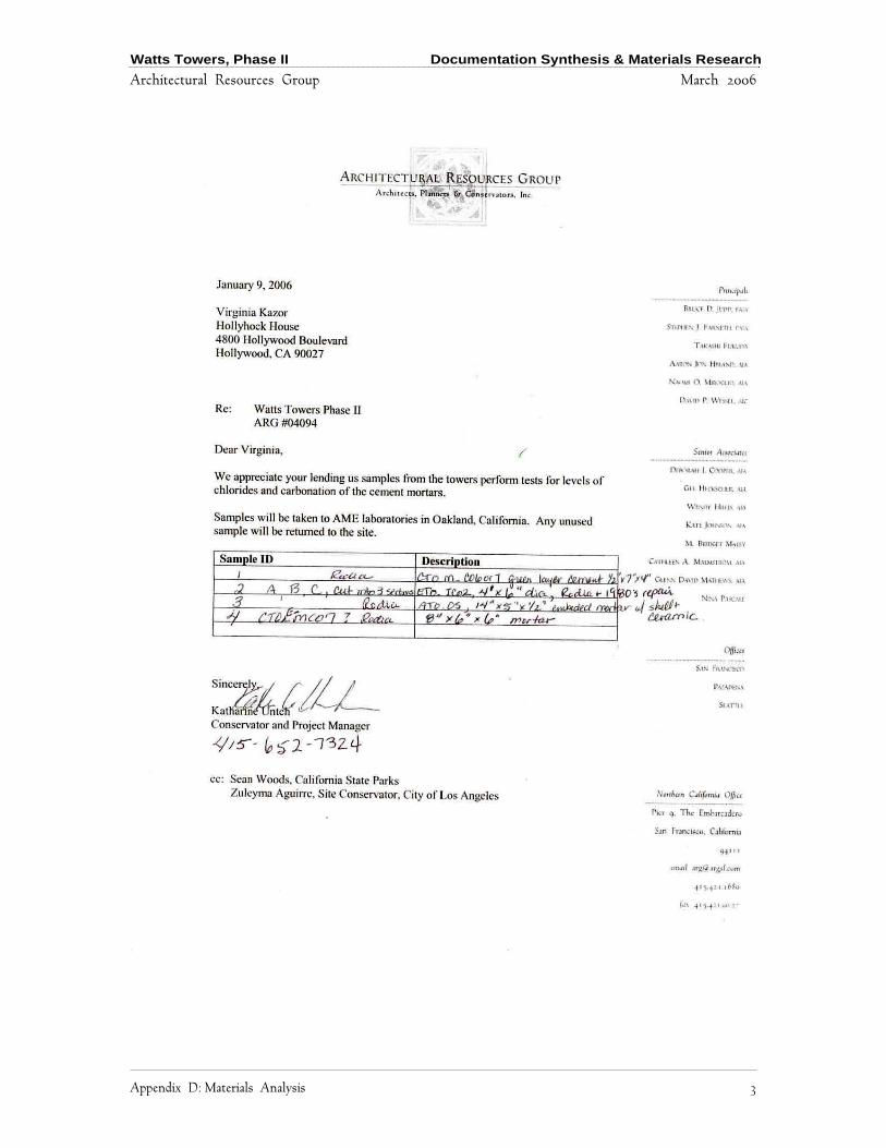
Watts Towers, Phase II Documentation Synthesis & Materials Research
Architectural Resources Group March 2006
Appendix D: Materials Analysis 3

Watts Towers, Phase II Documentation Synthesis & Materials Research
Architectural Resources Group March 2006
4 Appendix D: Materials Analysis
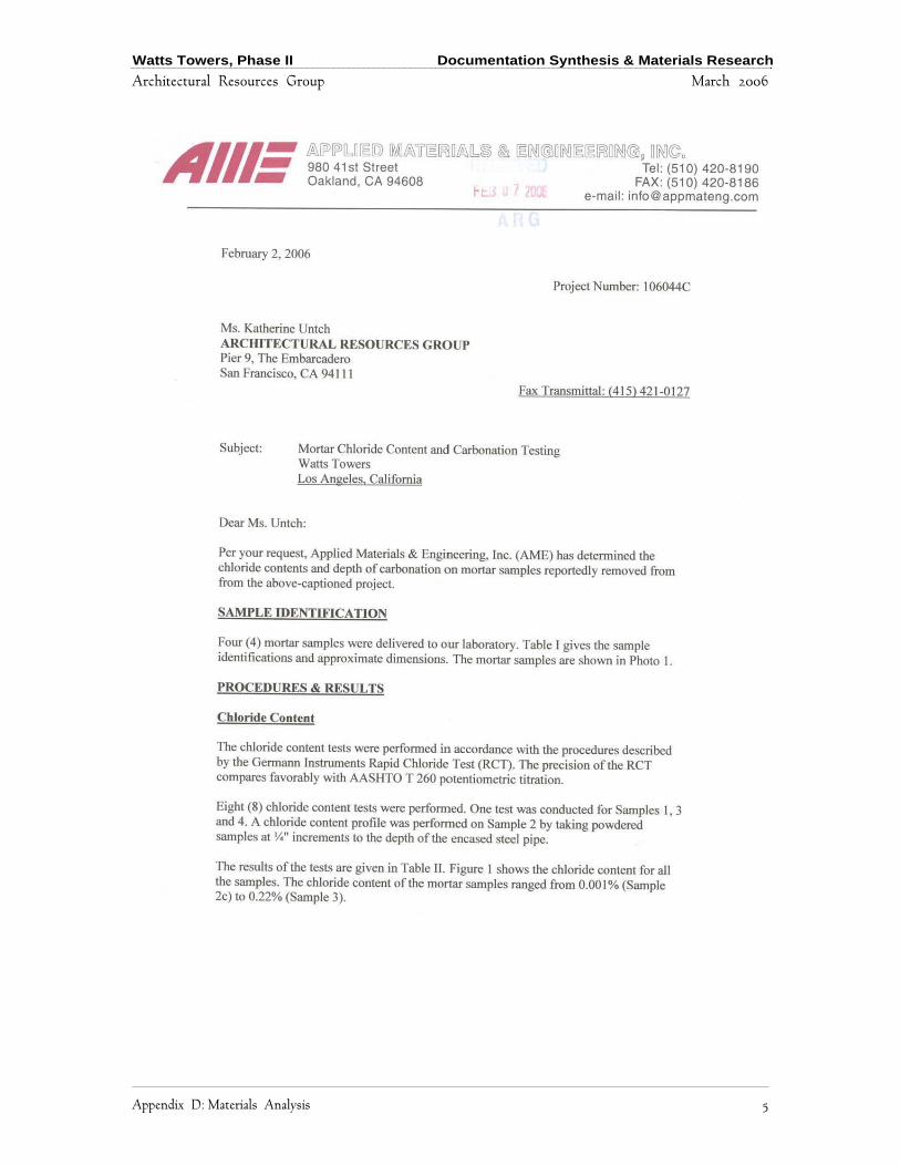
Watts Towers, Phase II Documentation Synthesis & Materials Research
Architectural Resources Group March 2006
Appendix D: Materials Analysis 5
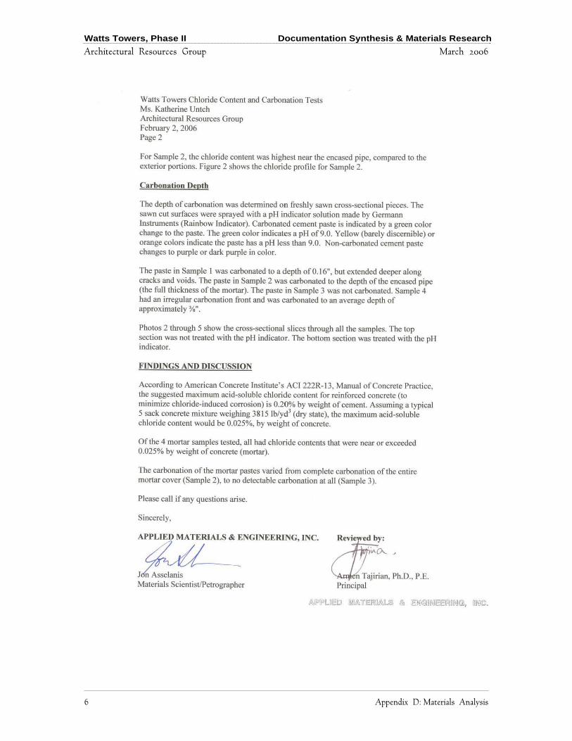
Watts Towers, Phase II Documentation Synthesis & Materials Research
Architectural Resources Group March 2006
6 Appendix D: Materials Analysis

Watts Towers, Phase II Documentation Synthesis & Materials Research
Architectural Resources Group March 2006
Appendix D: Materials Analysis 7
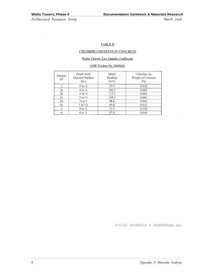
Watts Towers, Phase II Documentation Synthesis & Materials Research
Architectural Resources Group March 2006
8 Appendix D: Materials Analysis
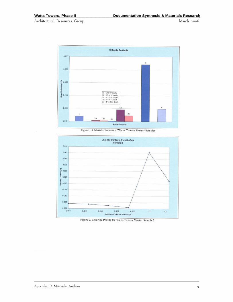
Watts Towers, Phase II Documentation Synthesis & Materials Research
Architectural Resources Group March 2006
Appendix D: Materials Analysis 9
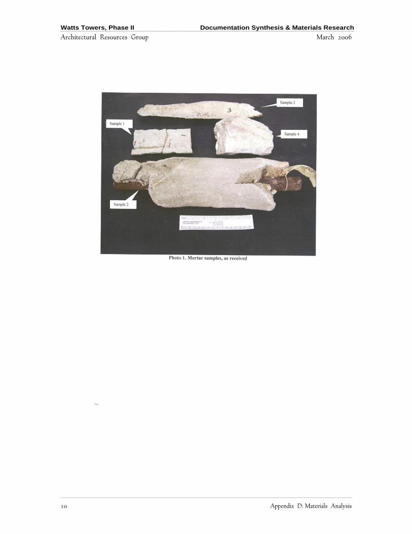
Watts Towers, Phase II Documentation Synthesis & Materials Research
Architectural Resources Group March 2006
10 Appendix D: Materials Analysis
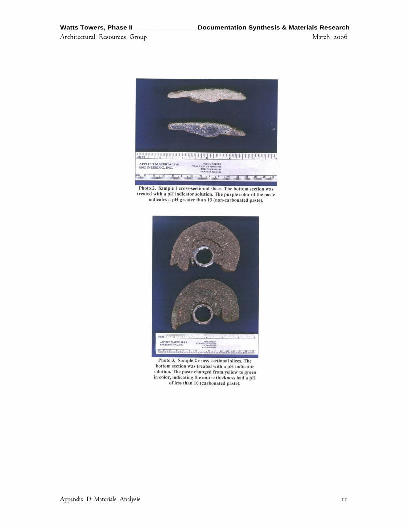
Watts Towers, Phase II Documentation Synthesis & Materials Research
Architectural Resources Group March 2006
Appendix D: Materials Analysis 11
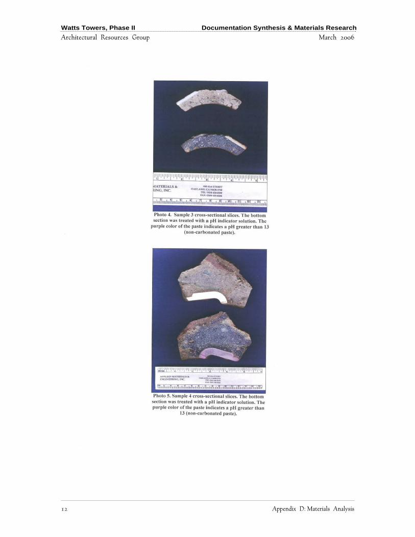
Watts Towers, Phase II Documentation Synthesis & Materials Research
Architectural Resources Group March 2006
12 Appendix D: Materials Analysis
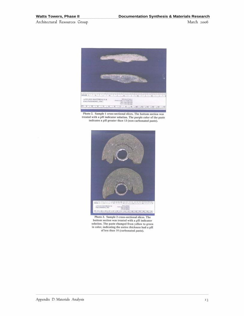
Watts Towers, Phase II Documentation Synthesis & Materials Research
Architectural Resources Group March 2006
Appendix D: Materials Analysis 13

Watts Towers, Phase II Documentation Synthesis & Materials Research
Architectural Resources Group March 2006
14 Appendix D: Materials Analysis
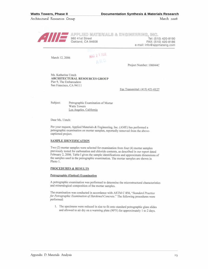
Watts Towers, Phase II Documentation Synthesis & Materials Research
Architectural Resources Group March 2006
Appendix D: Materials Analysis 15
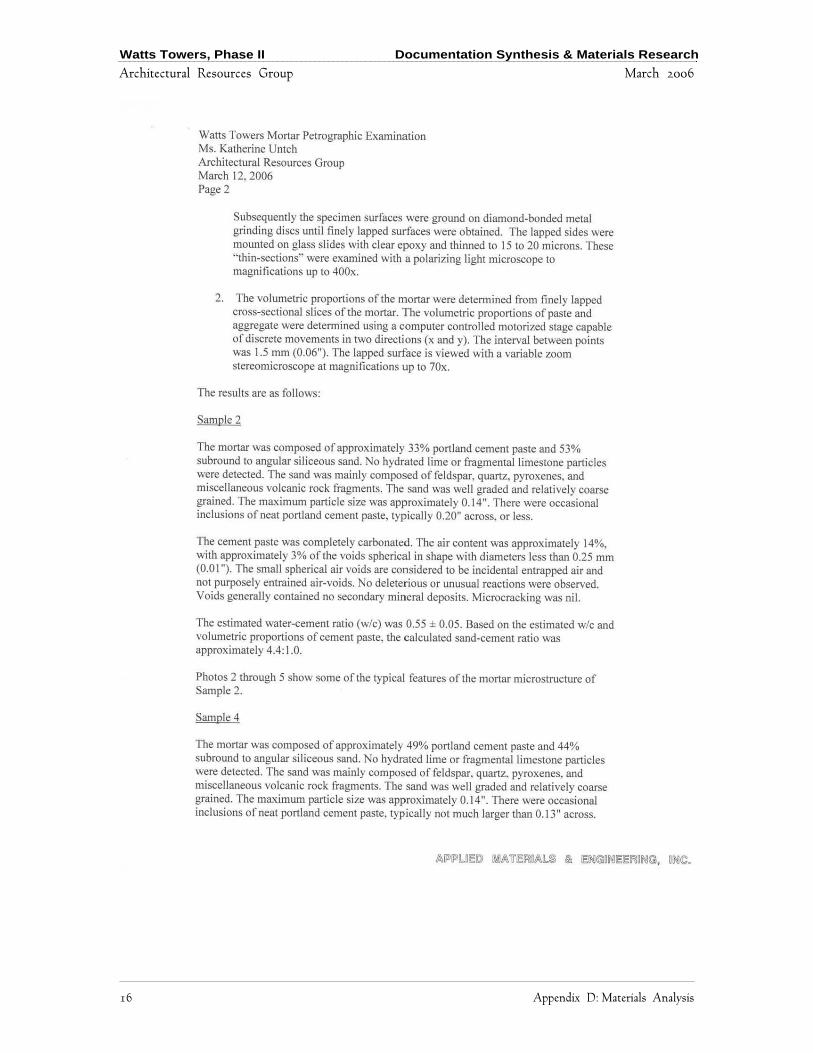
Watts Towers, Phase II Documentation Synthesis & Materials Research
Architectural Resources Group March 2006
16 Appendix D: Materials Analysis
Watts Towers, Phase II Documentation Synthesis & Materials Research
Architectural Resources Group March 2006
Appendix D: Materials Analysis 17

Watts Towers, Phase II Documentation Synthesis & Materials Research
Architectural Resources Group March 2006
18 Appendix D: Materials Analysis

Watts Towers, Phase II Documentation Synthesis & Materials Research
Architectural Resources Group March 2006
Appendix D: Materials Analysis 19

Watts Towers, Phase II Documentation Synthesis & Materials Research
Architectural Resources Group March 2006
20 Appendix D: Materials Analysis

Watts Towers, Phase II Documentation Synthesis & Materials Research
Architectural Resources Group March 2006
Appendix D: Materials Analysis 21

Watts Towers, Phase II Documentation Synthesis & Materials Research
Architectural Resources Group March 2006
22 Appendix D: Materials Analysis
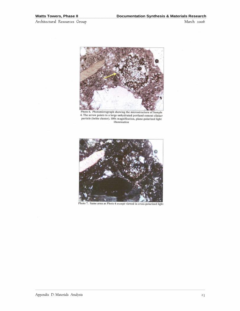
Watts Towers, Phase II Documentation Synthesis & Materials Research
Architectural Resources Group March 2006
Appendix D: Materials Analysis 23
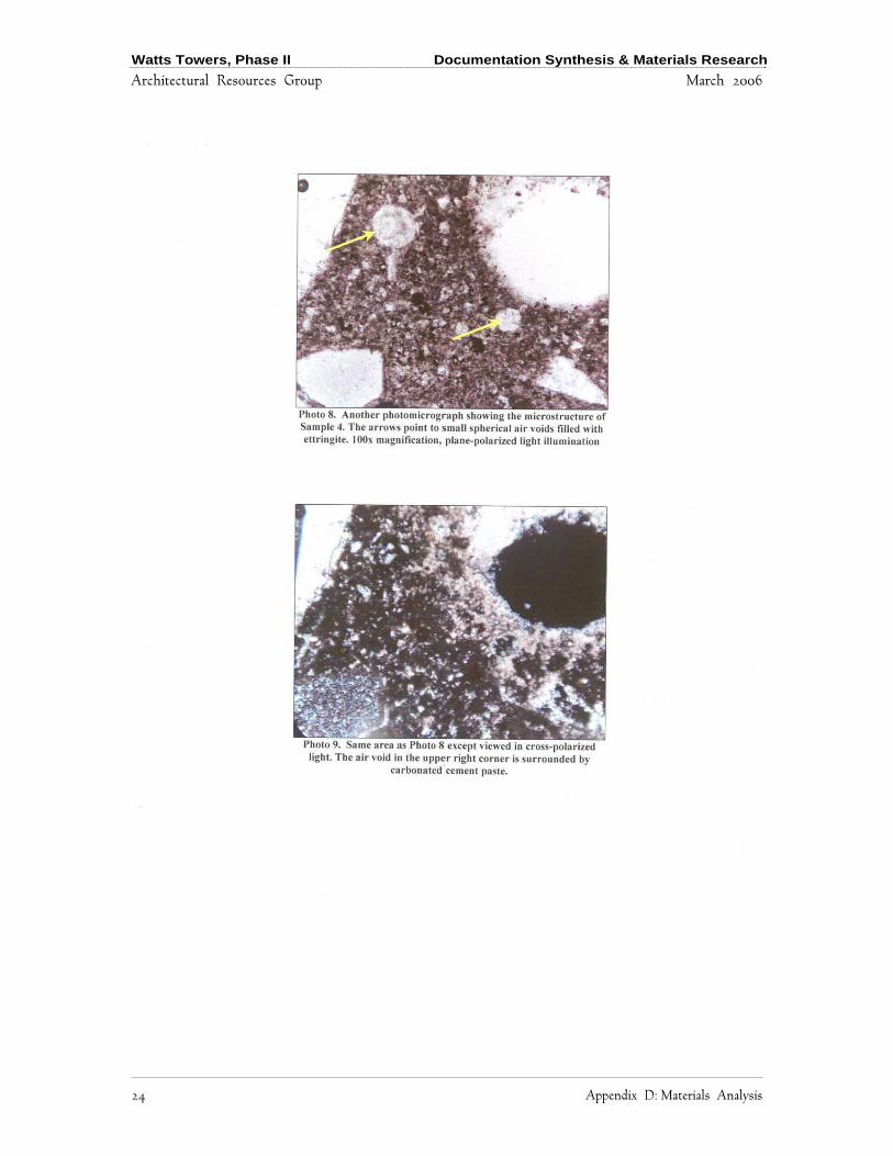
Watts Towers, Phase II Documentation Synthesis & Materials Research
Architectural Resources Group March 2006
24 Appendix D: Materials Analysis
Watts Towers, Phase II Documentation Synthesis & Materials Research
Architectural Resources Group March 2006
Appendix D: Materials Analysis 25
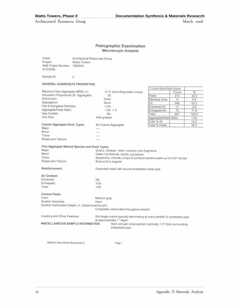
Watts Towers, Phase II Documentation Synthesis & Materials Research
Architectural Resources Group March 2006
26 Appendix D: Materials Analysis
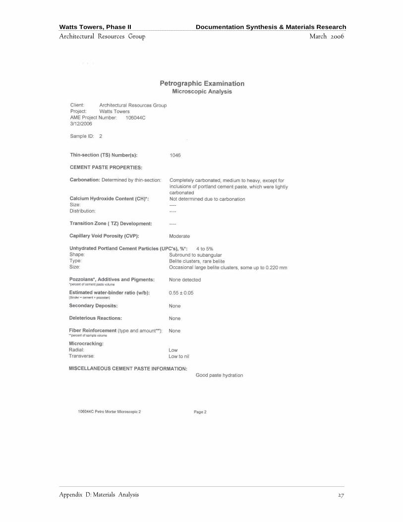
Watts Towers, Phase II Documentation Synthesis & Materials Research
Architectural Resources Group March 2006
Appendix D: Materials Analysis 27
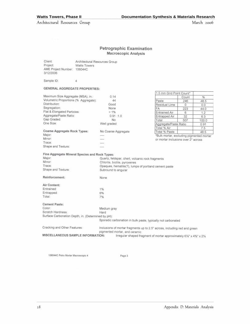
Watts Towers, Phase II Documentation Synthesis & Materials Research
Architectural Resources Group March 2006
28 Appendix D: Materials Analysis

Watts Towers, Phase II Documentation Synthesis & Materials Research
Architectural Resources Group March 2006
Appendix D: Materials Analysis 29

Watts Towers, Phase II Documentation Synthesis & Materials Research
Architectural Resources Group March 2006
30 Appendix D: Materials Analysis

Watts Towers, Phase II Documentation Synthesis & Materials Research
Architectural Resources Group March 2006
Appendix D: Materials Analysis 31
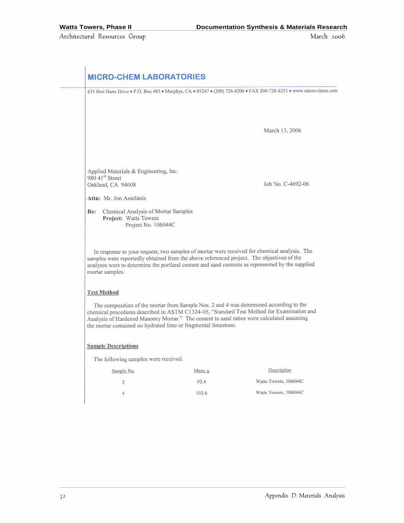
Watts Towers, Phase II Documentation Synthesis & Materials Research
Architectural Resources Group March 2006
32 Appendix D: Materials Analysis

Watts Towers, Phase II Documentation Synthesis & Materials Research
Architectural Resources Group March 2006
Appendix D: Materials Analysis 33

Watts Towers, Phase II Documentation Synthesis & Materials Research
Architectural Resources Group March 2006
34 Appendix D: Materials Analysis
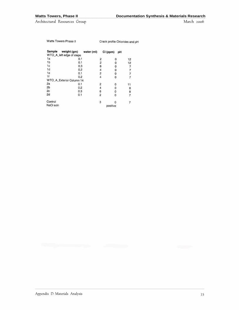
Watts Towers, Phase II Documentation Synthesis & Materials Research
Architectural Resources Group March 2006
Appendix D: Materials Analysis 35

Watts Towers, Phase II Documentation Synthesis & Materials Research
Architectural Resources Group March 31, 2006

Watts Towers, Phase II Documentation Synthesis & Materials Research
Architectural Resources Group March 2006
Appendix E: Material Data Sheets 1
Appendix E: Material Data Sheets

Watts Towers, Phase II Documentation Synthesis & Materials Research
Architectural Resources Group March 2006
2 Appendix E: Material Data Sheets
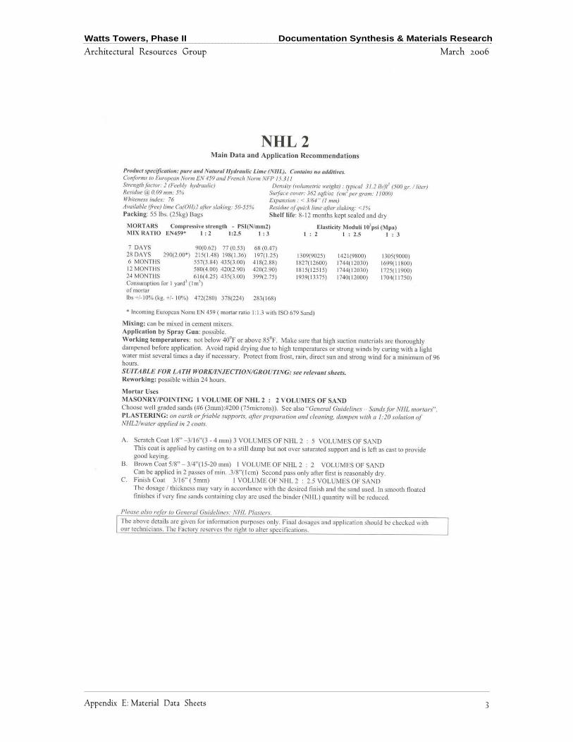
Watts Towers, Phase II Documentation Synthesis & Materials Research
Architectural Resources Group March 2006
Appendix E: Material Data Sheets 3
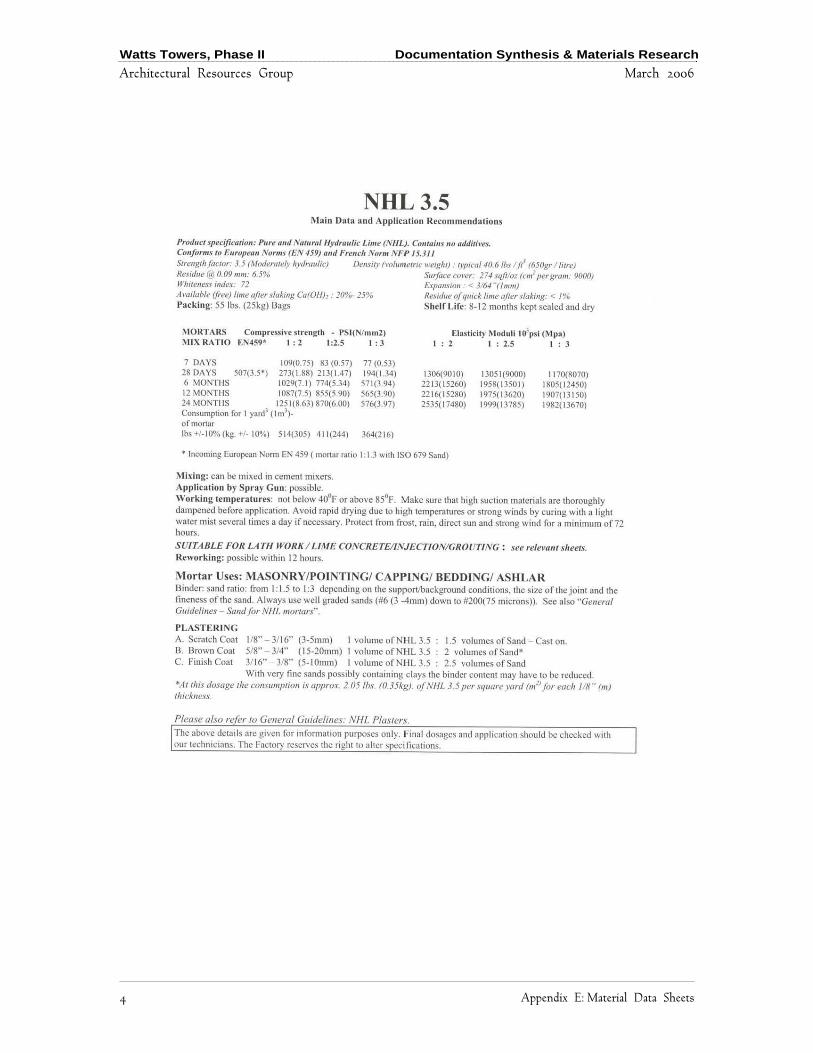
Watts Towers, Phase II Documentation Synthesis & Materials Research
Architectural Resources Group March 2006
4 Appendix E: Material Data Sheets

Watts Towers, Phase II Documentation Synthesis & Materials Research
Architectural Resources Group March 2006
Appendix E: Material Data Sheets 5

Watts Towers, Phase II Documentation Synthesis & Materials Research
Architectural Resources Group March 2006
6 Appendix E: Material Data Sheets

Watts Towers, Phase II Documentation Synthesis & Materials Research
Architectural Resources Group March 2006
Appendix E: Material Data Sheets 7
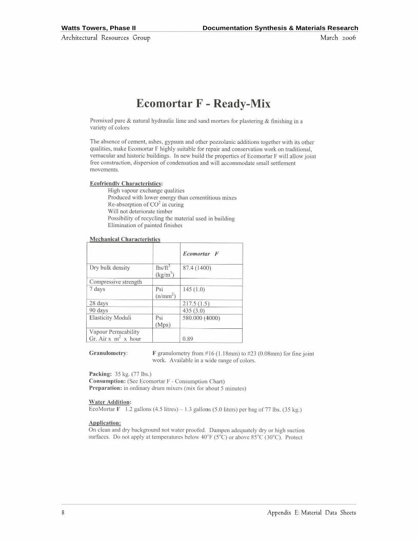
Watts Towers, Phase II Documentation Synthesis & Materials Research
Architectural Resources Group March 2006
8 Appendix E: Material Data Sheets

Watts Towers, Phase II Documentation Synthesis & Materials Research
Architectural Resources Group March 2006
Appendix E: Material Data Sheets 9

Watts Towers, Phase II Documentation Synthesis & Materials Research
Architectural Resources Group March 31, 2006
![[MS-OXOTASK]: Task-Related Objects Protocol...[MS-OXOTASK]: Task-Related Objects Protocol Intellectual Property Rights Notice for Open Specifications Documentation Technical Documentation.](https://static.fdocuments.us/doc/165x107/5f8eb50ee0f268036973fc19/ms-oxotask-task-related-objects-protocol-ms-oxotask-task-related-objects.jpg)