Documentation KL1501 - Directory contents of … · Documentation KL1501 Up/Down-Counter Terminal,...
39
Documentation KL1501 Up/Down-Counter Terminal, 24 VDC, 100 kHz 3.0.0 2017-04-05 Version: Date:
Transcript of Documentation KL1501 - Directory contents of … · Documentation KL1501 Up/Down-Counter Terminal,...
Documentation
KL1501
Up/Down-Counter Terminal, 24 VDC, 100 kHz
3.0.02017-04-05
Version:Date:


Table of contents
KL1501 3Version: 3.0.0
Table of contents1 Foreword .................................................................................................................................................... 4
1.1 Notes on the documentation........................................................................................................... 41.2 Safety instructions .......................................................................................................................... 51.3 Documentation issue status............................................................................................................ 6
2 Product overview....................................................................................................................................... 72.1 KL1501 - Introduction ..................................................................................................................... 72.2 KL1501 - Technical data................................................................................................................. 82.3 KL1501 - LED displays ................................................................................................................... 9
3 Mounting and wiring ............................................................................................................................... 103.1 Installation on mounting rails ........................................................................................................ 103.2 Installation instructions for enhanced mechanical load capacity .................................................. 133.3 Connection system ....................................................................................................................... 133.4 KL1501 - Connection .................................................................................................................... 173.5 ATEX - Special conditions (extended temperature range) ........................................................... 183.6 ATEX Documentation ................................................................................................................... 19
4 KS2000 Configuration software ............................................................................................................. 204.1 KS2000 - Introduction ................................................................................................................... 20
5 Access from the user program .............................................................................................................. 225.1 Terminal configuration .................................................................................................................. 225.2 Mapping in the Bus Coupler ......................................................................................................... 24
5.2.1 Standard format ............................................................................................................... 245.2.2 Alternative format ............................................................................................................. 25
5.3 Register overview ......................................................................................................................... 265.4 Register description ...................................................................................................................... 265.5 Control and status byte................................................................................................................. 29
5.5.1 Process data exchange ................................................................................................... 295.5.2 Register communication................................................................................................... 30
5.6 Examples of Register Communication.......................................................................................... 315.6.1 Example 1: reading the firmware version from Register 9 of a terminal .......................... 315.6.2 Example 2: Writing to an user register ............................................................................. 31
5.7 Data exchange, function ............................................................................................................... 34
6 TwinCAT ................................................................................................................................................... 356.1 Programming ................................................................................................................................ 366.2 Function block FB_KL1501Config ................................................................................................ 36
7 Appendix .................................................................................................................................................. 387.1 Support and Service ..................................................................................................................... 38

Foreword
KL15014 Version: 3.0.0
1 Foreword
1.1 Notes on the documentation
Intended audience
This description is only intended for the use of trained specialists in control and automation engineering whoare familiar with the applicable national standards.It is essential that the documentation and the following notes and explanations are followed when installingand commissioning these components.It is the duty of the technical personnel to use the documentation published at the respective time of eachinstallation and commissioning.
The responsible staff must ensure that the application or use of the products described satisfy all therequirements for safety, including all the relevant laws, regulations, guidelines and standards.
Disclaimer
The documentation has been prepared with care. The products described are, however, constantly underdevelopment.
We reserve the right to revise and change the documentation at any time and without prior announcement.
No claims for the modification of products that have already been supplied may be made on the basis of thedata, diagrams and descriptions in this documentation.
Trademarks
Beckhoff®, TwinCAT®, EtherCAT®, Safety over EtherCAT®, TwinSAFE®, XFC® and XTS® are registeredtrademarks of and licensed by Beckhoff Automation GmbH.Other designations used in this publication may be trademarks whose use by third parties for their ownpurposes could violate the rights of the owners.
Patent Pending
The EtherCAT Technology is covered, including but not limited to the following patent applications andpatents: EP1590927, EP1789857, DE102004044764, DE102007017835 with corresponding applications orregistrations in various other countries.
The TwinCAT Technology is covered, including but not limited to the following patent applications andpatents: EP0851348, US6167425 with corresponding applications or registrations in various other countries.
EtherCAT® is registered trademark and patented technology, licensed by Beckhoff Automation GmbH,Germany
Copyright
© Beckhoff Automation GmbH & Co. KG, Germany.The reproduction, distribution and utilization of this document as well as the communication of its contents toothers without express authorization are prohibited.Offenders will be held liable for the payment of damages. All rights reserved in the event of the grant of apatent, utility model or design.
Foreword
KL1501 5Version: 3.0.0
1.2 Safety instructions
Safety regulations
Please note the following safety instructions and explanations!Product-specific safety instructions can be found on following pages or in the areas mounting, wiring,commissioning etc.
Exclusion of liability
All the components are supplied in particular hardware and software configurations appropriate for theapplication. Modifications to hardware or software configurations other than those described in thedocumentation are not permitted, and nullify the liability of Beckhoff Automation GmbH & Co. KG.
Personnel qualification
This description is only intended for trained specialists in control, automation and drive engineering who arefamiliar with the applicable national standards.
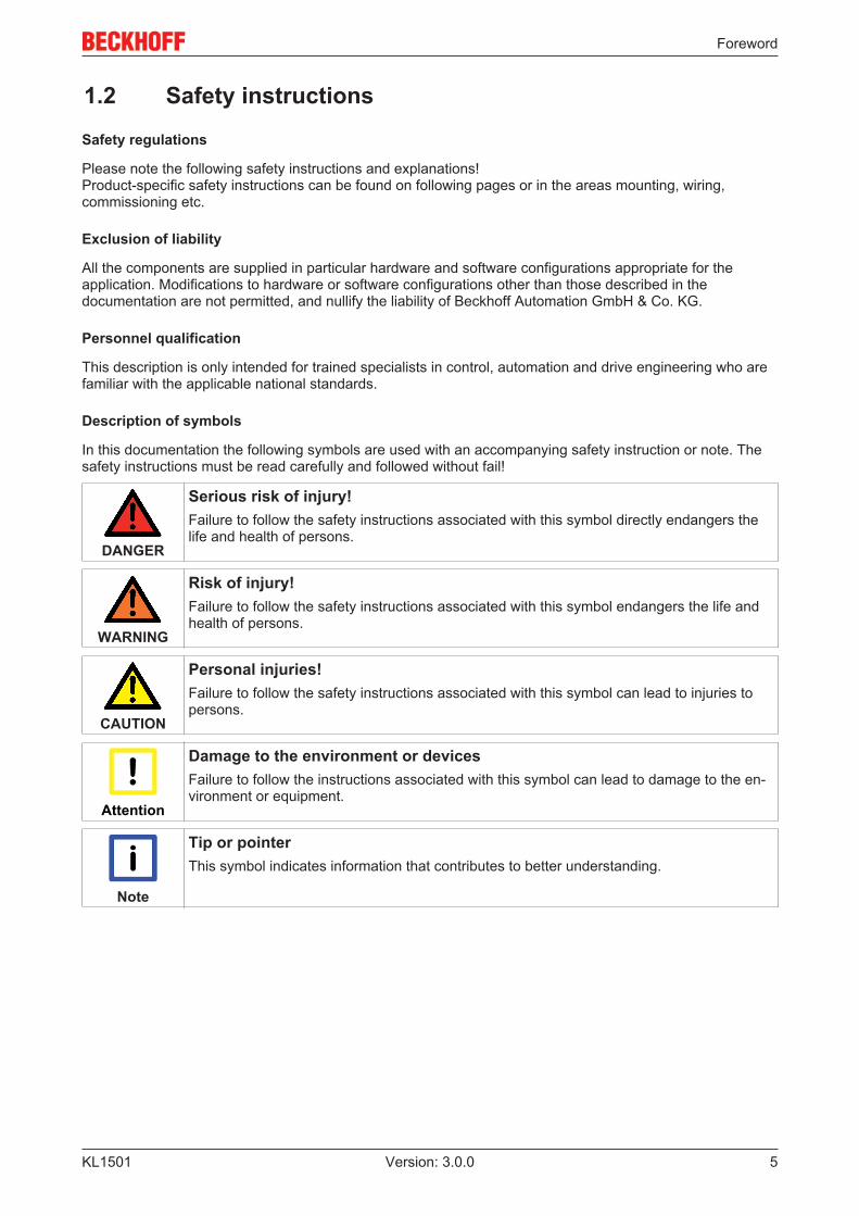
Description of symbols
In this documentation the following symbols are used with an accompanying safety instruction or note. Thesafety instructions must be read carefully and followed without fail!
DANGER
Serious risk of injury!Failure to follow the safety instructions associated with this symbol directly endangers thelife and health of persons.
WARNING
Risk of injury!Failure to follow the safety instructions associated with this symbol endangers the life andhealth of persons.
CAUTION
Personal injuries!Failure to follow the safety instructions associated with this symbol can lead to injuries topersons.
Attention
Damage to the environment or devicesFailure to follow the instructions associated with this symbol can lead to damage to the en-vironment or equipment.
Note
Tip or pointerThis symbol indicates information that contributes to better understanding.
Foreword
KL15016 Version: 3.0.0
1.3 Documentation issue statusVersion Comment3.0.0 • Migration
• Structure update• Technical data updated• Installation instructions for enhanced mechanical load capacity added• Chapter "TwinCAT" including Link to FB_KL1501Config added• Revision status updated
Firmware and hardware versions
DocumentationVersion
KL1501Firmware Hardware
3.0.0 3B 08
The K-bus firmware and hardware version (delivery state) are indicated by the serial number printed at theside of the terminal.
Syntax of the serial number
Structure of the serial number: WW YY FF HH
WW - week of production (calendar week)YY - year of productionFF - K-bus firmware versionHH - hardware version
Example with ser. no.: 49 05 1B 03:
49 - week of production 4905 - year of production 20051B - firmware version 1B03 - hardware version 03
Product overview
KL1501 7Version: 3.0.0
2 Product overview
2.1 KL1501 - Introduction
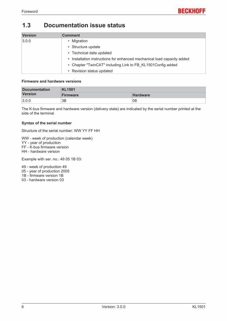
Fig. 1: KL1501
The KL1501 input terminal counts binary pulses and transfers the current value to the higher-level controller.In addition to the 32-bit up/down counter, a 32-bit gated counter and two 16-bit counters are available. Ingated counter mode, a low or high level at the gate input disables the counting function of the terminal. If two16-bit counters are active, the up/down input is the clock input for the second counter. In addition, two digitaloutputs can be set.
The maximum input frequency is limited to 100 kHz, the minimum pulse width of the input signal is approx.1 microsecond. The counters respond to the rising edge of the input signal.
The following controller options are available via the control byte: setting the counter value, disabling thecounting function of the terminal, enabling the outputs. In addition an internal function can be enabled, whichenables automatic setting of the outputs for defined counter values.
The LEDs indicate the state of the up/down and clock inputs and of outputs 1 and 2.
The representation of the process data differs depending on the set function.
• In the standard output format, 5 bytes (4 bytes user data and 1 control/status byte) are mapped. Therepresentation of the process data differs depending on the set function.
◦ Up/down counter: 32 bit signed integer◦ Gated counter: 32 bit unsigned integer◦ Two active counters: 2 x 16 bit unsigned integer
• If the alternative output format is selected, note that the output length (4 bytes or 6 bytes instead of5 bytes) and the terminal mapping will change.
◦ Up/down counter: 24 bit signed integer◦ Gated counter: 24 bit signed integer◦ Two active counters: 1 x 8 bit counter 0 and 1 x 16 bit counter 1
The terminal mapping is described in more detail in chapter Mapping in the Bus Coupler [} 24].

Product overview
KL15018 Version: 3.0.0
2.2 KL1501 - Technical dataTechnical data KL1501Number of counters 1 or 2Rated load voltage 24 VDC (-15 %/+20 %)Signal voltage ‘0’ -3 V ... 5 VSignal voltage ‘1’ 15 V ... 30 VSwitching frequency 100 kHz (2 kHz for up/down switching)Input current typically 5 mAMax. output current 0.5 A typ. (short-circuit-proof) per channelK-bus current consumption typically 50 mACounter depth 32 bit or 2 x 16 bitElectrical isolation 500 V (K-bus / field voltage)Bit width in the process image 40 I/O: 32 bit data, 8 bit control/statusConfiguration no address setting, configuration via the Bus Coupler or the
controllerWeight approx. 50 gPermissible ambient temperature at operation -25 °C ... +60 °C (extended temperature range)Permissible ambient temperature at storage -40 °C ... +85 °CPermissible relative humidity 95%, no condensationVibration / shock resistance conforms to EN 60068-2-6 / EN 60068-2-27,
see also Installation instructions for enhanced mechanicalload capacity [} 13]
EMC immunity/emission conforms to EN 61000-6-2 / EN 61000-6-4Installation position anyProtection class IP20Approvals CE,
cULus,ATEX [} 18]
Product overview
KL1501 9Version: 3.0.0
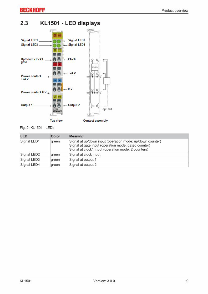
2.3 KL1501 - LED displays
Fig. 2: KL1501 - LEDs
LED Color MeaningSignal LED1 green Signal at up/down input (operation mode: up/down counter)
Signal at gate input (operation mode: gated counter)Signal at clock1 input (operation mode: 2 counters)
Signal LED2 green Signal at clock inputSignal LED3 green Signal at output 1Signal LED4 green Signal at output 2

Mounting and wiring
KL150110 Version: 3.0.0
3 Mounting and wiring
3.1 Installation on mounting rails
WARNING
Risk of electric shock and damage of device!Bring the bus terminal system into a safe, powered down state before starting installation,disassembly or wiring of the Bus Terminals!
Assembly
Fig. 3: Attaching on mounting rail
The Bus Coupler and Bus Terminals are attached to commercially available 35 mm mounting rails (DIN railsaccording to EN 60715) by applying slight pressure:
1. First attach the Fieldbus Coupler to the mounting rail.2. The Bus Terminals are now attached on the right-hand side of the Fieldbus Coupler. Join the compo-
nents with tongue and groove and push the terminals against the mounting rail, until the lock clicksonto the mounting rail.If the Terminals are clipped onto the mounting rail first and then pushed together without tongue andgroove, the connection will not be operational! When correctly assembled, no significant gap shouldbe visible between the housings.
Note
Fixing of mounting railsThe locking mechanism of the terminals and couplers extends to the profile of the mountingrail. At the installation, the locking mechanism of the components must not come into con-flict with the fixing bolts of the mounting rail. To mount the mounting rails with a height of7.5 mm under the terminals and couplers, you should use flat mounting connections (e.g.countersunk screws or blind rivets).
Mounting and wiring
KL1501 11Version: 3.0.0
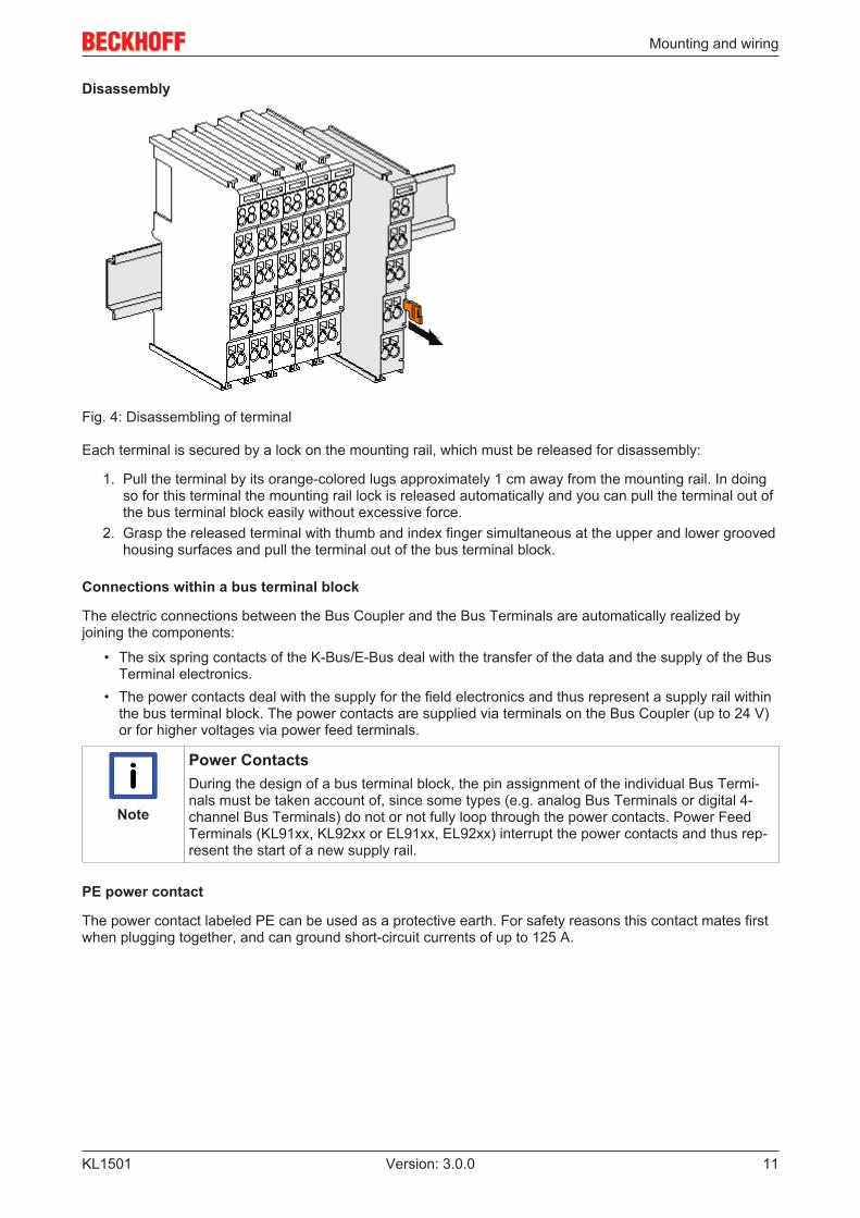
Disassembly
Fig. 4: Disassembling of terminal
Each terminal is secured by a lock on the mounting rail, which must be released for disassembly:
1. Pull the terminal by its orange-colored lugs approximately 1 cm away from the mounting rail. In doingso for this terminal the mounting rail lock is released automatically and you can pull the terminal out ofthe bus terminal block easily without excessive force.
2. Grasp the released terminal with thumb and index finger simultaneous at the upper and lower groovedhousing surfaces and pull the terminal out of the bus terminal block.
Connections within a bus terminal block
The electric connections between the Bus Coupler and the Bus Terminals are automatically realized byjoining the components:
• The six spring contacts of the K-Bus/E-Bus deal with the transfer of the data and the supply of the BusTerminal electronics.
• The power contacts deal with the supply for the field electronics and thus represent a supply rail withinthe bus terminal block. The power contacts are supplied via terminals on the Bus Coupler (up to 24 V)or for higher voltages via power feed terminals.
Note
Power ContactsDuring the design of a bus terminal block, the pin assignment of the individual Bus Termi-nals must be taken account of, since some types (e.g. analog Bus Terminals or digital 4-channel Bus Terminals) do not or not fully loop through the power contacts. Power FeedTerminals (KL91xx, KL92xx or EL91xx, EL92xx) interrupt the power contacts and thus rep-resent the start of a new supply rail.
PE power contact
The power contact labeled PE can be used as a protective earth. For safety reasons this contact mates firstwhen plugging together, and can ground short-circuit currents of up to 125 A.

Mounting and wiring
KL150112 Version: 3.0.0
Fig. 5: Power contact on left side
Attention
Possible damage of the deviceNote that, for reasons of electromagnetic compatibility, the PE contacts are capacitativelycoupled to the mounting rail. This may lead to incorrect results during insulation testing orto damage on the terminal (e.g. disruptive discharge to the PE line during insulation testingof a consumer with a nominal voltage of 230 V). For insulation testing, disconnect the PEsupply line at the Bus Coupler or the Power Feed Terminal! In order to decouple furtherfeed points for testing, these Power Feed Terminals can be released and pulled at least10 mm from the group of terminals.
WARNING
Risk of electric shock!The PE power contact must not be used for other potentials!
Mounting and wiring
KL1501 13Version: 3.0.0
3.2 Installation instructions for enhanced mechanical loadcapacity
WARNING
Risk of injury through electric shock and damage to the device!Bring the Bus Terminal system into a safe, de-energized state before starting mounting,disassembly or wiring of the Bus Terminals!
Additional checks
The terminals have undergone the following additional tests:
Verification ExplanationVibration 10 frequency runs in 3 axes
6 Hz < f < 60 Hz displacement 0.35 mm, constant amplitude60.1 Hz < f < 500 Hz acceleration 5 g, constant amplitude
Shocks 1000 shocks in each direction, in 3 axes25 g, 6 ms
Additional installation instructions
For terminals with enhanced mechanical load capacity, the following additional installation instructions apply:
• The enhanced mechanical load capacity is valid for all permissible installation positions• Use a mounting rail according to EN 60715 TH35-15• Fix the terminal segment on both sides of the mounting rail with a mechanical fixture, e.g. an earth
terminal or reinforced end clamp• The maximum total extension of the terminal segment (without coupler) is:
64 terminals (12 mm mounting with) or 32 terminals (24 mm mounting with)• Avoid deformation, twisting, crushing and bending of the mounting rail during edging and installation of
the rail• The mounting points of the mounting rail must be set at 5 cm intervals• Use countersunk head screws to fasten the mounting rail• The free length between the strain relief and the wire connection should be kept as short as possible. A
distance of approx. 10 cm should be maintained to the cable duct.
3.3 Connection system
WARNING
Risk of electric shock and damage of device!Bring the bus terminal system into a safe, powered down state before starting installation,disassembly or wiring of the Bus Terminals!
Overview
The Bus Terminal system offers different connection options for optimum adaptation to the respectiveapplication:
• The terminals of KLxxxx and ELxxxx series with standard wiring include electronics and connectionlevel in a single enclosure.
• The terminals of KSxxxx and ESxxxx series feature a pluggable connection level and enable steadywiring while replacing.
• The High Density Terminals (HD Terminals) include electronics and connection level in a singleenclosure and have advanced packaging density.

Mounting and wiring
KL150114 Version: 3.0.0
Standard wiring
Fig. 6: Standard wiring
The terminals of KLxxxx and ELxxxx series have been tried and tested for years.They feature integrated screwless spring force technology for fast and simple assembly.
Pluggable wiring
Fig. 7: Pluggable wiring
The terminals of KSxxxx and ESxxxx series feature a pluggable connection level.The assembly and wiring procedure for the KS series is the same as for the KLxxxx and ELxxxx series.The KS/ES series terminals enable the complete wiring to be removed as a plug connector from the top ofthe housing for servicing.The lower section can be removed from the terminal block by pulling the unlocking tab. Insert the new component and plug in the connector with the wiring. This reduces the installation time andeliminates the risk of wires being mixed up.
The familiar dimensions of the terminal only had to be changed slightly. The new connector adds about 3mm. The maximum height of the terminal remains unchanged.
A tab for strain relief of the cable simplifies assembly in many applications and prevents tangling of individualconnection wires when the connector is removed.
Conductor cross sections between 0.08 mm2 and 2.5 mm2 can continue to be used with the proven springforce technology.
The overview and nomenclature of the product names for KSxxxx and ESxxxx series has been retained asknown from KLxxxx and ELxxxx series.
High Density Terminals (HD Terminals)
Fig. 8: High Density Terminals
The Bus Terminals from these series with 16 connection points are distinguished by a particularly compactdesign, as the packaging density is twice as large as that of the standard 12 mm Bus Terminals. Massiveconductors and conductors with a wire end sleeve can be inserted directly into the spring loaded terminalpoint without tools.
Mounting and wiring
KL1501 15Version: 3.0.0
Note
Wiring HD TerminalsThe High Density (HD) Terminals of the KLx8xx and ELx8xx series doesn't support steadywiring.
Ultrasonically "bonded" (ultrasonically welded) conductors
Note
Ultrasonically “bonded" conductorsIt is also possible to connect the Standard and High Density Terminals with ultrasonically"bonded" (ultrasonically welded) conductors. In this case, please note the tables concern-ing the wire-size width [} 15] below!
Wiring
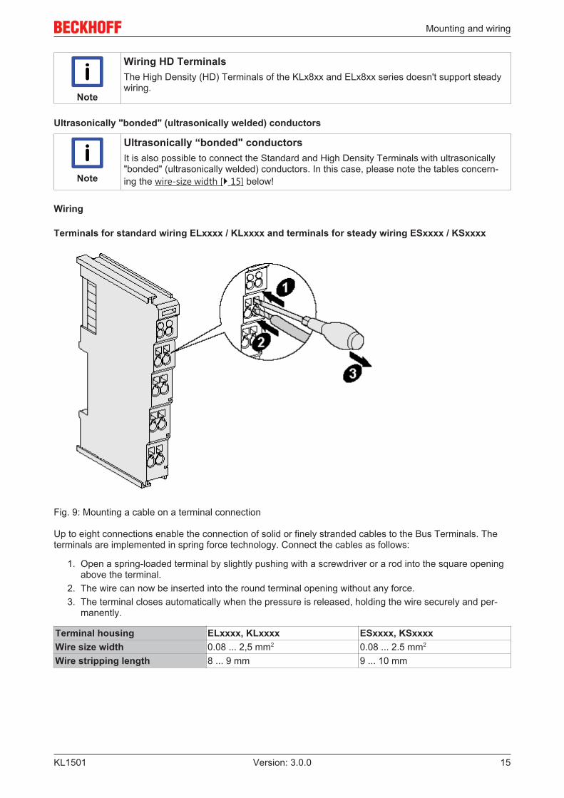
Terminals for standard wiring ELxxxx / KLxxxx and terminals for steady wiring ESxxxx / KSxxxx
Fig. 9: Mounting a cable on a terminal connection
Up to eight connections enable the connection of solid or finely stranded cables to the Bus Terminals. Theterminals are implemented in spring force technology. Connect the cables as follows:
1. Open a spring-loaded terminal by slightly pushing with a screwdriver or a rod into the square openingabove the terminal.
2. The wire can now be inserted into the round terminal opening without any force.3. The terminal closes automatically when the pressure is released, holding the wire securely and per-
manently.
Terminal housing ELxxxx, KLxxxx ESxxxx, KSxxxxWire size width 0.08 ... 2,5 mm2 0.08 ... 2.5 mm2
Wire stripping length 8 ... 9 mm 9 ... 10 mm

Mounting and wiring
KL150116 Version: 3.0.0
High Density Terminals ELx8xx, KLx8xx (HD)
The conductors of the HD Terminals are connected without tools for single-wire conductors using the directplug-in technique, i.e. after stripping the wire is simply plugged into the contact point. The cables arereleased, as usual, using the contact release with the aid of a screwdriver. See the following table for thesuitable wire size width.
Terminal housing High Density HousingWire size width (conductors with a wire end sleeve) 0.14... 0.75 mm2
Wire size width (single core wires) 0.08 ... 1.5 mm2
Wire size width (fine-wire conductors) 0.25 ... 1.5 mm2
Wire size width (ultrasonically “bonded" conductors) only 1.5 mm2 (see notice[} 15]!)
Wire stripping length 8 ... 9 mm
Shielding
Note
ShieldingAnalog sensors and actors should always be connected with shielded, twisted paired wires.
Mounting and wiring
KL1501 17Version: 3.0.0
3.4 KL1501 - Connection
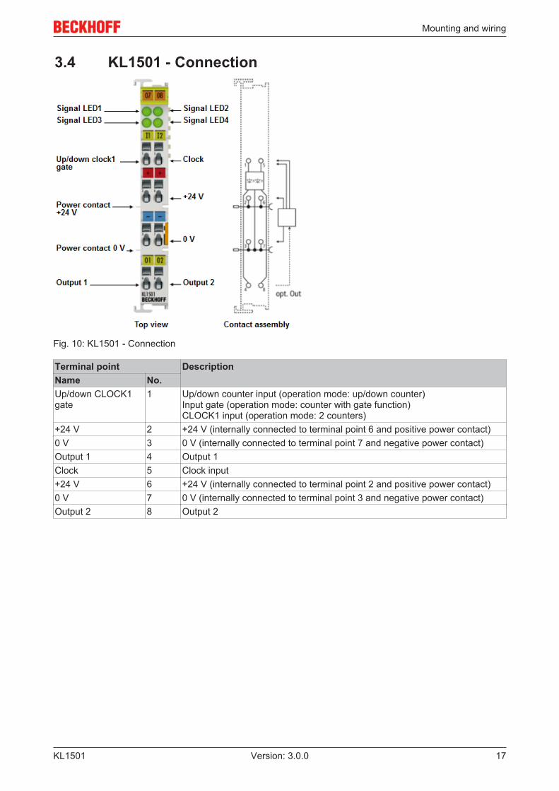
Fig. 10: KL1501 - Connection
Terminal point DescriptionName No.Up/down CLOCK1gate
1 Up/down counter input (operation mode: up/down counter)Input gate (operation mode: counter with gate function)CLOCK1 input (operation mode: 2 counters)
+24 V 2 +24 V (internally connected to terminal point 6 and positive power contact)0 V 3 0 V (internally connected to terminal point 7 and negative power contact)Output 1 4 Output 1Clock 5 Clock input+24 V 6 +24 V (internally connected to terminal point 2 and positive power contact)0 V 7 0 V (internally connected to terminal point 3 and negative power contact)Output 2 8 Output 2

Mounting and wiring
KL150118 Version: 3.0.0
3.5 ATEX - Special conditions (extended temperaturerange)
WARNING
Observe the special conditions for the intended use of Beckhoff fieldbuscomponents with extended temperature range (ET) in potentially explosiveareas (directive 94/9/EU)!
• The certified components are to be installed in a suitable housing that guarantees aprotection class of at least IP54 in accordance with EN 60529! The environmental con-ditions during use are thereby to be taken into account!
• If the temperatures during rated operation are higher than 70°C at the feed-in points ofcables, lines or pipes, or higher than 80°C at the wire branching points, then cablesmust be selected whose temperature data correspond to the actual measured tempera-ture values!
• Observe the permissible ambient temperature range of -25 to 60°C for the use of Beck-hoff fieldbus components with extended temperature range (ET) in potentially explosiveareas!
• Measures must be taken to protect against the rated operating voltage being exceededby more than 40% due to short-term interference voltages!
• The individual terminals may only be unplugged or removed from the Bus Terminal sys-tem if the supply voltage has been switched off or if a non-explosive atmosphere is en-sured!
• The connections of the certified components may only be connected or disconnected ifthe supply voltage has been switched off or if a non-explosive atmosphere is ensured!
• The fuses of the KL92xx/EL92xx power feed terminals may only be exchanged if thesupply voltage has been switched off or if a non-explosive atmosphere is ensured!
• Address selectors and ID switches may only be adjusted if the supply voltage has beenswitched off or if a non-explosive atmosphere is ensured!
Standards
The fundamental health and safety requirements are fulfilled by compliance with the following standards:
• EN 60079-0:2012+A11:2013• EN 60079-15:2010
Marking
The Beckhoff fieldbus components with extended temperature range (ET) certified for potentially explosiveareas bear the following marking:
II 3G KEMA 10ATEX0075 X Ex nA IIC T4 Gc Ta: -25 … 60°C
or
II 3G KEMA 10ATEX0075 X Ex nC IIC T4 Gc Ta: -25 … 60°C
Mounting and wiring
KL1501 19Version: 3.0.0
3.6 ATEX Documentation
Note
Notes about operation of the Beckhoff terminal systems in potentially explo-sive areas (ATEX)Pay also attention to the continuative documentation
Notes about operation of the Beckhoff terminal systems in potentially explosive areas(ATEX)
that is available in the download area of the Beckhoff homepage http:\\www.beckhoff.com!
KS2000 Configuration software
KL150120 Version: 3.0.0
4 KS2000 Configuration software
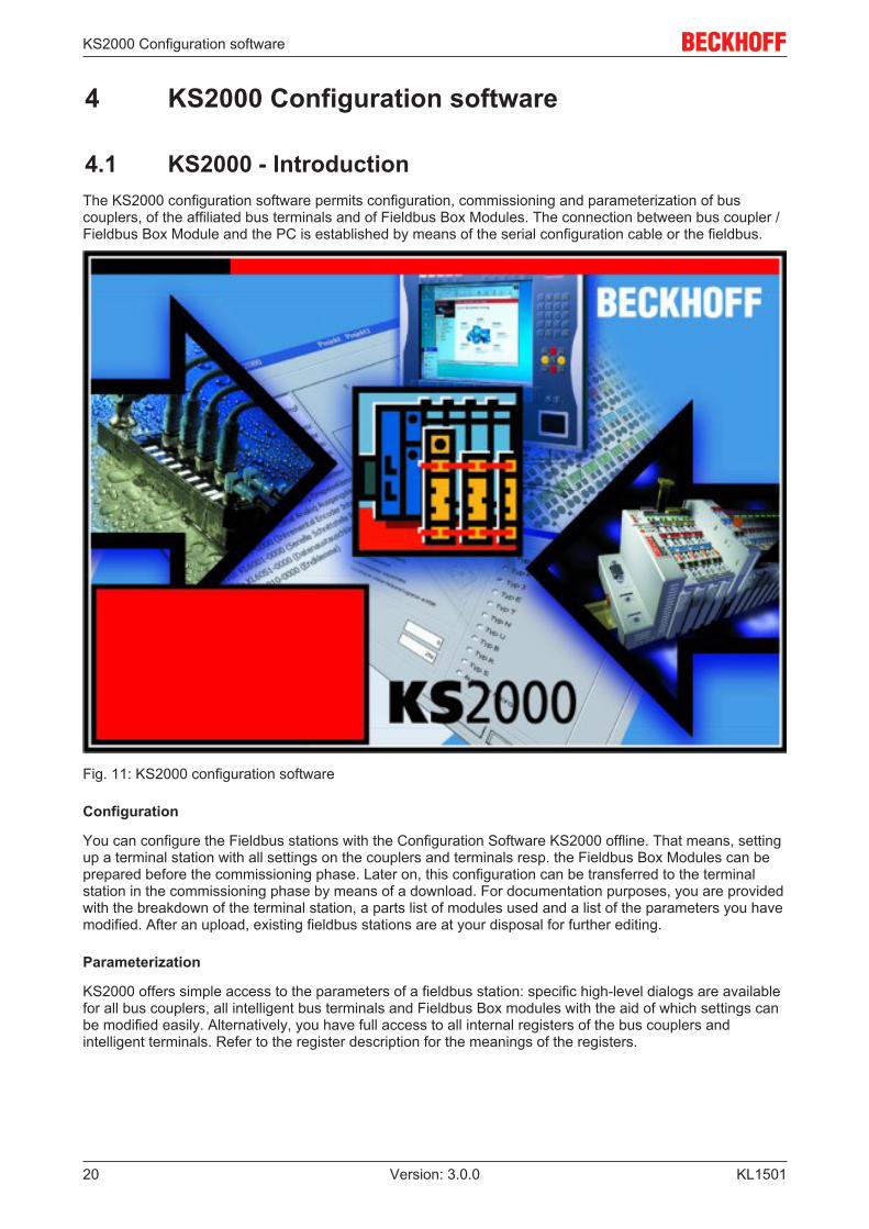
4.1 KS2000 - IntroductionThe KS2000 configuration software permits configuration, commissioning and parameterization of buscouplers, of the affiliated bus terminals and of Fieldbus Box Modules. The connection between bus coupler /Fieldbus Box Module and the PC is established by means of the serial configuration cable or the fieldbus.
Fig. 11: KS2000 configuration software
Configuration
You can configure the Fieldbus stations with the Configuration Software KS2000 offline. That means, settingup a terminal station with all settings on the couplers and terminals resp. the Fieldbus Box Modules can beprepared before the commissioning phase. Later on, this configuration can be transferred to the terminalstation in the commissioning phase by means of a download. For documentation purposes, you are providedwith the breakdown of the terminal station, a parts list of modules used and a list of the parameters you havemodified. After an upload, existing fieldbus stations are at your disposal for further editing.
Parameterization
KS2000 offers simple access to the parameters of a fieldbus station: specific high-level dialogs are availablefor all bus couplers, all intelligent bus terminals and Fieldbus Box modules with the aid of which settings canbe modified easily. Alternatively, you have full access to all internal registers of the bus couplers andintelligent terminals. Refer to the register description for the meanings of the registers.

KS2000 Configuration software
KL1501 21Version: 3.0.0
Commissioning
The KS2000 software facilitates commissioning of machine components or their fieldbus stations: Configuredsettings can be transferred to the fieldbus modules by means of a download. After a login to the terminalstation, it is possible to define settings in couplers, terminals and Fieldbus Box modules directly online. Thesame high-level dialogs and register access are available for this purpose as in the configuration phase.
The KS2000 offers access to the process images of the bus couplers and Fieldbus Box modules.
• Thus, the coupler's input and output images can be observed by monitoring.• Process values can be specified in the output image for commissioning of the output modules.
All possibilities in the online mode can be used in parallel with the actual fieldbus mode of the terminalstation. The fieldbus protocol always has the higher priority in this case.
Access from the user program
KL150122 Version: 3.0.0
5 Access from the user program
5.1 Terminal configurationThe terminal can be configured and parameterized via the internal register structure. Each terminal channelis mapped in the Bus Coupler. Mapping of the terminal data in the Bus Coupler memory may differ,depending on the Bus Coupler type and the set mapping configuration (e.g. Motorola/Intel format, wordalignment etc.).
Note
In contrast to analog input and output terminals, in the KL1501 the control byte and the sta-tus byte are always mapped, irrespective of the fieldbus system used.
BK2000 Lightbus Coupler
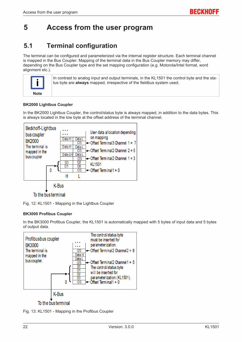
In the BK2000 Lightbus Coupler, the control/status byte is always mapped, in addition to the data bytes. Thisis always located in the low byte at the offset address of the terminal channel.
Fig. 12: KL1501 - Mapping in the Lightbus Coupler
BK3000 Profibus Coupler
In the BK3000 Profibus Coupler, the KL1501 is automatically mapped with 5 bytes of input data and 5 bytesof output data.
Fig. 13: KL1501 - Mapping in the Profibus Coupler
Access from the user program
KL1501 23Version: 3.0.0
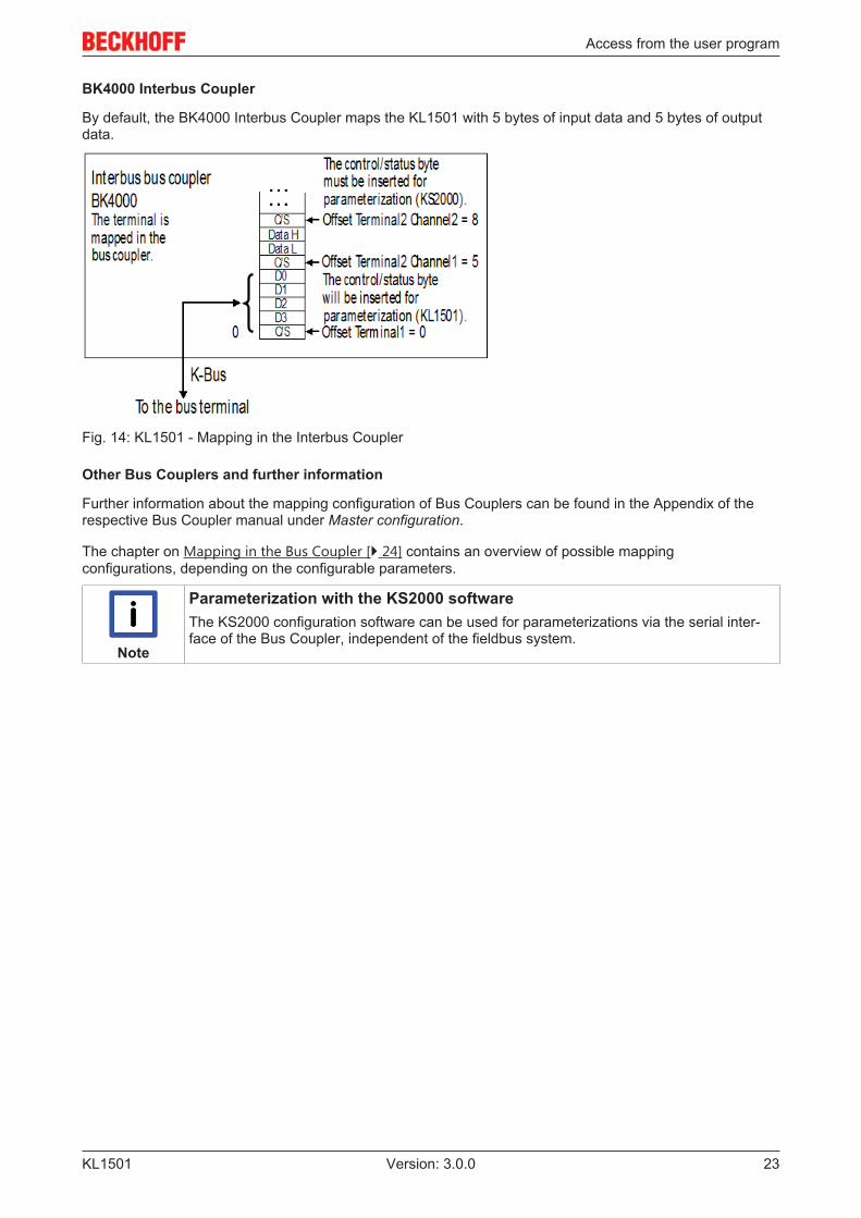
BK4000 Interbus Coupler
By default, the BK4000 Interbus Coupler maps the KL1501 with 5 bytes of input data and 5 bytes of outputdata.
Fig. 14: KL1501 - Mapping in the Interbus Coupler
Other Bus Couplers and further information
Further information about the mapping configuration of Bus Couplers can be found in the Appendix of therespective Bus Coupler manual under Master configuration.
The chapter on Mapping in the Bus Coupler [} 24] contains an overview of possible mappingconfigurations, depending on the configurable parameters.
Note
Parameterization with the KS2000 softwareThe KS2000 configuration software can be used for parameterizations via the serial inter-face of the Bus Coupler, independent of the fieldbus system.

Access from the user program
KL150124 Version: 3.0.0
5.2 Mapping in the Bus CouplerAs already described in the Terminal Configuration chapter, each Bus Terminal is mapped in the BusCoupler. This mapping is usually done with the default setting in the Bus Coupler / Bus Terminal. TheKS2000 configuration software or a master configuration software (e.g. ComProfibus or TwinCAT SystemManager) can be used to change this default setting.
The following tables shows the mapping of the KL1501 in the Bus Coupler, depending on the setparameters.
5.2.1 Standard formatIn the standard format, the KL1501 is mapped with 5 bytes of input data and 5 bytes of output data.
Default mapping for: CAN, DeviceNet, ControlNet, Modbus, RS232 and RS485 Couplers
Requirements Word offset High byte Low byteComplete evaluation: anyMotorola format: noWord alignment: no
0 D0 CB/SB1 D2 D12 Res. D3
Default mapping for: Profibus and Interbus Coupler
Requirements Word offset High byte Low byteComplete evaluation: anyMotorola format: yesWord alignment: no
0 D3 CB/SB1 D1 D22 Res. D0
Default mapping for: Lightbus & Ethernet coupler and Bus Terminal Controller (BCxxxx, BXxxxx)
Requirements Word offset High byte Low byteComplete evaluation: anyMotorola format: noWord alignment: yes
0 Res. CB/SB1 D1 D02 D3 D2
Requirements Word offset High byte Low byteComplete evaluation: anyMotorola format: yesWord alignment: yes
0 Res CB/SB1 D2 D32 D0 D1
Legend
Complete evaluation: The terminal is mapped with control and status byte.Motorola format Motorola or Intel format can be set.Word alignment The terminal is positioned on a word boundary in the Bus Coupler.CB Control byte (appears in the process image of the outputs).SB Status byte (appears in the process image of the inputs).D0 Data byte 0D1 Data byte 1D2 Data byte 2D3 Data byte 3Res. This byte is assigned to the process data memory, although it has no function.
Access from the user program
KL1501 25Version: 3.0.0
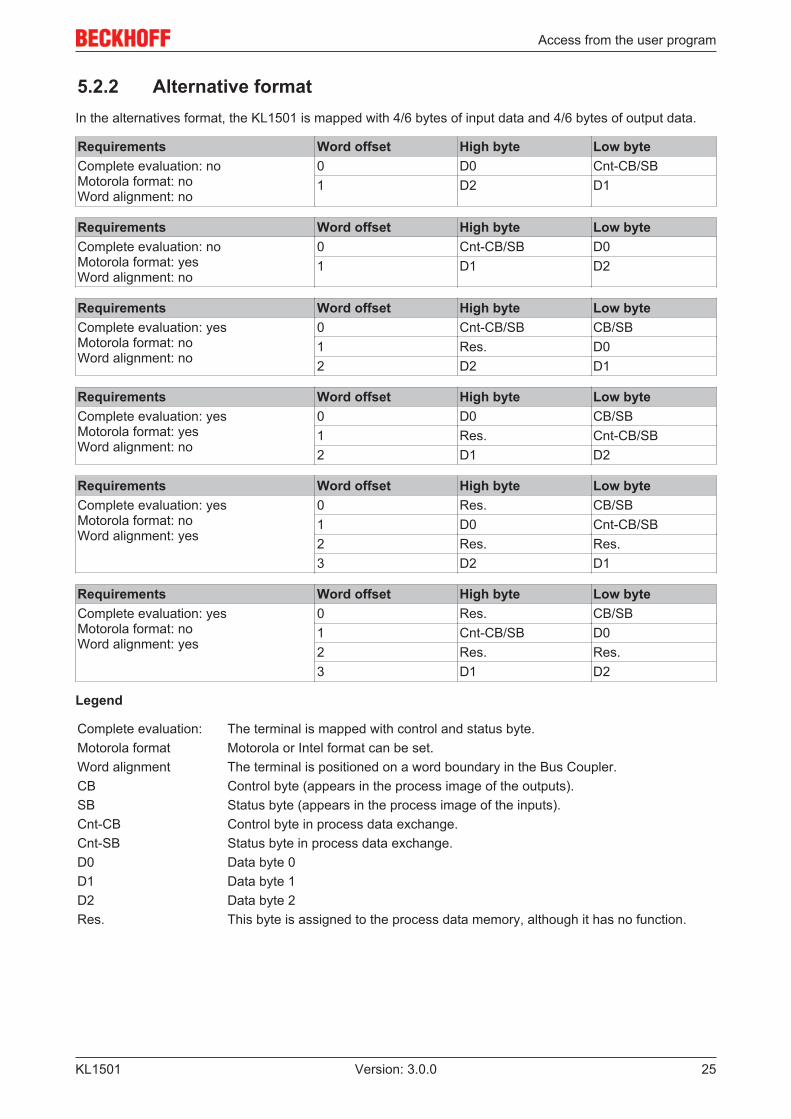
5.2.2 Alternative formatIn the alternatives format, the KL1501 is mapped with 4/6 bytes of input data and 4/6 bytes of output data.
Requirements Word offset High byte Low byteComplete evaluation: noMotorola format: noWord alignment: no
0 D0 Cnt-CB/SB1 D2 D1
Requirements Word offset High byte Low byteComplete evaluation: noMotorola format: yesWord alignment: no
0 Cnt-CB/SB D01 D1 D2
Requirements Word offset High byte Low byteComplete evaluation: yesMotorola format: noWord alignment: no
0 Cnt-CB/SB CB/SB1 Res. D02 D2 D1
Requirements Word offset High byte Low byteComplete evaluation: yesMotorola format: yesWord alignment: no
0 D0 CB/SB1 Res. Cnt-CB/SB2 D1 D2
Requirements Word offset High byte Low byteComplete evaluation: yesMotorola format: noWord alignment: yes
0 Res. CB/SB1 D0 Cnt-CB/SB2 Res. Res.3 D2 D1
Requirements Word offset High byte Low byteComplete evaluation: yesMotorola format: noWord alignment: yes
0 Res. CB/SB1 Cnt-CB/SB D02 Res. Res.3 D1 D2
Legend
Complete evaluation: The terminal is mapped with control and status byte.Motorola format Motorola or Intel format can be set.Word alignment The terminal is positioned on a word boundary in the Bus Coupler.CB Control byte (appears in the process image of the outputs).SB Status byte (appears in the process image of the inputs).Cnt-CB Control byte in process data exchange.Cnt-SB Status byte in process data exchange.D0 Data byte 0D1 Data byte 1D2 Data byte 2Res. This byte is assigned to the process data memory, although it has no function.

Access from the user program
KL150126 Version: 3.0.0
5.3 Register overviewAddress Name Default value R/W Storage mediumR0 reserved 0x0000 R ... ... ... ... ...R5 reserved 0x0000 RR6 [} 26] Diagnostic register - reserved 0x0000 R
R7 [} 26] Command register - reserved 0x0000 R
R8 [} 26] Terminal type 1501 R ROM
R9 [} 27] Software version number 0x???? R ROM
R10 [} 27] Multiplex shift register 0x0130 R ROM
R11 [} 27] Signal channels 0x0128 R ROM
R12 [} 27] Minimum data length 0x2828 R ROM
R13 [} 27] Data structure 0x0000 R ROMR14 reserved 0x0000 RR15 [} 27] Alignment register variable R/W RAM
R16 [} 27] Hardware version number 0x???? R/W SEEROMR17 reserved 0x0000 R/W SEEROM ... ... ... ... ...R30 reserved 0x0000 R/W SEEROMR31 [} 27] Code word register variable R/W RAM
R32 [} 28] Feature register 0x0100 R/W SEEROMR33 reserved 0x0000 R/W SEEROM ... ... ... ... ...R63 reserved 0x0000 R/W SEEROM
5.4 Register descriptionThe registers can be read or written via the register communication. They are used for the parameterizationof the terminal.
R0 to R7: Registers in the internal RAM of the terminal
The process variables can be used in addition to the actual process image. Their function is specific to theterminal.
• R6: Diagnostic registerThe diagnostic register can contain additional diagnostic information. Parity errors, for instance, thatoccur in serial interface terminals during data transmission are indicated here.
• R7: Command registerHigh-Byte_Write = function parameterLow-Byte_Write = function numberHigh-Byte_Read = function resultLow-Byte_Read = function number
R8 to R15: Registers in the internal ROM of the terminal
The type and system parameters are hard programmed by the manufacturer, and the user can read thembut cannot change them.
• R8: Terminal typeThe terminal type in register R8 is needed to identify the terminal.

Access from the user program
KL1501 27Version: 3.0.0
• R9: Software version (X.y)The software version can be read as a string of ASCII characters.
• R10: Data lengthR10 contains the number of multiplexed shift registers and their length in bits.The Bus Coupler sees this structure.
• R11: Signal channelsRelated to R10, this contains the number of channels that are logically present. Thus for example ashift register that is physically present can perfectly well consist of several signal channels.
• R12: Minimum data lengthThe particular byte contains the minimum data length for a channel that is to be transferred. If the MSBis set, the control and status byte is not necessarily required for the terminal function and is nottransferred to the control, if the Bus Coupler is configured accordingly.
• R13: Data type register
Data type register Meaning0x00 Terminal with no valid data type0x01 Byte array0x02 Structure 1 byte n bytes0x03 Word array0x04 Structure 1 byte n words0x05 Double word array0x06 Structure 1 byte n double words0x07 Structure 1 byte 1 double word0x08 Structure 1 byte 1 double word0x11 Byte array with variable logical channel length0x12 Structure 1 byte n bytes with variable logical channel length (e.g. 60xx)0x13 Word array with variable logical channel length0x14 Structure 1 byte n words with variable logical channel length0x15 Double word array with variable logical channel length0x16 Structure 1 byte n double words with variable logical channel length
• R15: Alignment bits (RAM)The alignment bits are used to place the analog terminal in the Bus Coupler on a byte boundary.
R16 to R30: Manufacturer parameter area (SEEROM)
The manufacturer parameters are specific for each type of terminal. They are programmed by themanufacturer, but can also be modified by the controller. The manufacturer parameters are stored in a serialEEPROM in the terminal, and are retained in the event of voltage drop-out.
These registers can only be altered after a code word has been set in R31.
R31 to R47: User parameter area (SEEROM)
The user parameters are specific for each type of terminal. They can be modified by the programmer. Theuser parameters are stored in a serial EEPROM in the terminal, and are retained in the event of voltagedrop-out. The user area is write-protected by a code word.
Note
• R31: Code word register in RAMThe code word 0x1235 must be entered here so that parameters in the user area can bemodified. If any other value is entered into this register, the write-protection is active. Whenwrite protection is not active, the code word is returned when the register is read. If thewrite protection is active, the register contains a zero value.
• R32: Feature register[0x0100]This register specifies the operation modes of the terminal.
Access from the user program
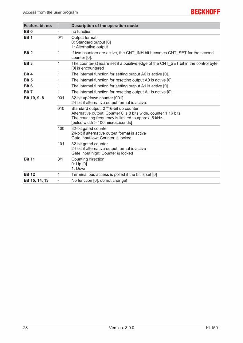
KL150128 Version: 3.0.0
Feature bit no. Description of the operation modeBit 0 - no functionBit 1 0/1 Output format
0: Standard output [0]1: Alternative output
Bit 2 1 If two counters are active, the CNT_INH bit becomes CNT_SET for the secondcounter [0].
Bit 3 1 The counter(s) is/are set if a positive edge of the CNT_SET bit in the control byte[0] is encountered
Bit 4 1 The internal function for setting output A0 is active [0].Bit 5 1 The internal function for resetting output A0 is active [0].Bit 6 1 The internal function for setting output A1 is active [0].Bit 7 1 The internal function for resetting output A1 is active [0].Bit 10, 9, 8 001 32-bit up/down counter [001].
24-bit if alternative output format is active.010 Standard output: 2 *16-bit up counter
Alternative output: Counter 0 is 8 bits wide, counter 1 16 bits.The counting frequency is limited to approx. 5 kHz.[pulse width > 100 microseconds]
100 32-bit gated counter24-bit if alternative output format is activeGate input low: Counter is locked
101 32-bit gated counter24-bit if alternative output format is activeGate input high: Counter is locked
Bit 11 0/1 Counting direction0: Up [0]1: Down
Bit 12 1 Terminal bus access is polled if the bit is set [0]Bit 15, 14, 13 - No function [0], do not change!

Access from the user program
KL1501 29Version: 3.0.0
5.5 Control and status byteThe control byte is transferred from the controller to the terminal. If can be used
• in register mode [} 30] (REG = 1bin) or
• in process data exchange [} 29] (REG = 0bin).
5.5.1 Process data exchange
Control byte in process data exchange (REG=0)
During process data exchange, the control byte is used to trigger various actions in the KL1501 counterterminal:
MSB
REG=0 0 CNT_SET CNT_INH SET_A1 SET_A0 EN_A1 EN_A0
Bit FunctionCNT_SET The counter is set to the value that is specified via the process data.
Setting of the counter can be edge-controlled or level-controlled (see R32.3).CNT_INH The counter is stopped, as long as this bit is active. The old counter value is maintained.
If two counters are active, the second counter can be set with this bit.SET_A1 Sets the second outputSET_A0 Sets the first outputEN_A1 This bit enables the internal function that was activated via R32.EN_A0 This bit enables the internal function that was activated via R32.
• Setting outputs A0, A1The control bits EN_A0 and EN_A1 can be used to activate the functions for setting the outputs. Thecontrol bits SET_A0 or SET_A1 are ignored if EN_A0, EN_A1 are set.
Status byte in process data exchange (REG=0)
The status byte is transferred from the terminal to the controller. The status byte contains various status bitsof the KL1501 counter terminal
MSB
REG=0 0 SET_ACC INH_ACC ST_A1 ST_A0 ST_V/R ST_CLK
Bit FunctionSET_ACC The data for setting the counter were accepted by the terminal.INH_ACC The counter is stopped as long as this bit is set.ST_A1 This bit indicates the state of output A1.ST_A0 This bit indicates the state of output A0.ST_V/R This bit indicates the state of the up/down input.ST_CLK This bit indicates the state of the CLOCK input.
Access from the user program
KL150130 Version: 3.0.0
5.5.2 Register communication
Register access via process data exchange• Bit 7=1: Register mode
If bit 7 of the control byte is set, the first two bytes of the user data are not used for process dataexchange but written into the register set of the terminal or read from it.
• Bit 6=0: read, bit 6=1: writeBit 6 of the control bytes is used to specify whether a register should be read or written.
◦ Bit 6=0: A register is read without changing it. The value can be found in the input processimage.
◦ Bit 6=1: The user data are written into a register. The process is complete once the statusbyte in the input process image has returned an acknowledgement (see example).
• Bits 0 to 5: AddressThe address of the register to be addressed is entered in bits 0 to 5 of the control byte.
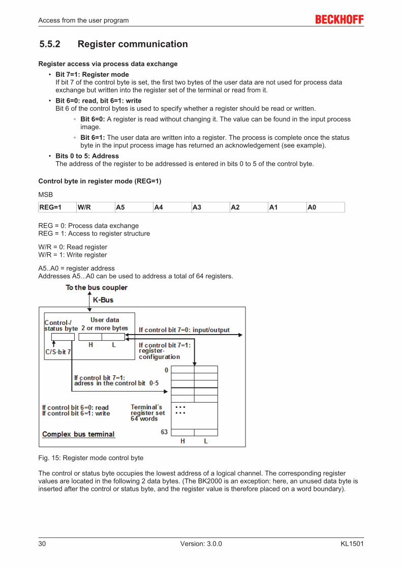
Control byte in register mode (REG=1)
MSB
REG=1 W/R A5 A4 A3 A2 A1 A0
REG = 0: Process data exchangeREG = 1: Access to register structure
W/R = 0: Read registerW/R = 1: Write register
A5..A0 = register addressAddresses A5...A0 can be used to address a total of 64 registers.
Fig. 15: Register mode control byte
The control or status byte occupies the lowest address of a logical channel. The corresponding registervalues are located in the following 2 data bytes. (The BK2000 is an exception: here, an unused data byte isinserted after the control or status byte, and the register value is therefore placed on a word boundary).

Access from the user program
KL1501 31Version: 3.0.0
5.6 Examples of Register CommunicationThe numbering of the bytes in the examples corresponds to the display without word alignment.
5.6.1 Example 1: reading the firmware version from Register 9 of aterminal
Output Data
Byte 0: Control byte Byte 1: DataOUT1, high byte Byte 2: DataOUT1, low byte0x89 (1000 1001bin) 0xXX 0xXX
Explanation:
• Bit 0.7 set means: Register communication switched on.• Bit 0.6 not set means: reading the register.• Bits 0.5 to 0.0 specify the register number 9 with 00 1001bin.• The output data word (byte 1 and byte 2) has no meaning during read access. To change a register,
write the required value into the output word.
Input Data (answer of the bus terminal)
Byte 0: Status byte Byte 1: DataIN1, high byte Byte 2: DataIN1, low byte0x89 0x33 0x41
Explanation:
• The terminal returns the value of the control byte as a receipt in the status byte.• The terminal returns the firmware version 0x3341 in the input data word (byte 1 and byte 2). This is to
be interpreted as an ASCII code:◦ ASCII code 0x33 represents the digit 3◦ ASCII code 0x41 represents the letter A
The firmware version is thus 3A.
5.6.2 Example 2: Writing to an user register
Note
Code wordIn normal mode all user registers are read-only with the exception of Register 31. In orderto deactivate this write protection you must write the code word (0x1235) into Register 31. Ifa value other than 0x1235 is written into Register 31, write protection is reactivated. Pleasenote that changes to a register only become effective after restarting the terminal (power-off/power-on).
I. Write the code word (0x1235) into Register 31.
Output Data
Byte 0: Control byte Byte 1: DataOUT1, high byte Byte 2: DataOUT1, low byte0xDF (1101 1111bin) 0x12 0x35
Explanation:
• Bit 0.7 set means: Register communication switched on.• Bit 0.6 set means: writing to the register.• Bits 0.5 to 0.0 specify the register number 31 with 01 1111bin.

Access from the user program
KL150132 Version: 3.0.0
• The output data word (byte 1 and byte 2) contains the code word (0x1235) for deactivating writeprotection.
Input Data (answer of the bus terminal)
Byte 0: Status byte Byte 1: DataIN1, high byte Byte 2: DataIN1, low byte0x9F (1001 1111bin) 0xXX 0xXX
Explanation:
• The terminal returns a value as a receipt in the status byte that differs only in bit 0.6 from the value ofthe control byte.
• The input data word (byte 1 and byte 2) is of no importance after the write access. Any values stilldisplayed are invalid!
II. Read Register 31 (check the set code word)
Output Data
Byte 0: Control byte Byte 1: DataOUT1, high byte Byte 2: DataOUT1, low byte0x9F (1001 1111bin) 0xXX 0xXX
Explanation:
• Bit 0.7 set means: Register communication switched on.• Bit 0.6 not set means: reading the register.• Bits 0.5 to 0.0 specify the register number 31 with 01 1111bin.• The output data word (byte 1 and byte 2) has no meaning during read access.
Input Data (answer of the bus terminal)
Byte 0: Status byte Byte 1: DataIN1, high byte Byte 2: DataIN1, low byte0x9F (1001 1111bin) 0x12 0x35
Explanation:
• The terminal returns the value of the control byte as a receipt in the status byte.• The terminal returns the current value of the code word register in the input data word (byte 1 and byte
2).
III. Write to Register 32 (change contents of the feature register)
Output Data
Byte 0: Control byte Byte 1: DataIN1, high byte Byte 2: DataIN1, low byte0xE0 (1110 0000bin) 0x00 0x02
Explanation:
• Bit 0.7 set means: Register communication switched on.• Bit 0.6 set means: writing to the register.• Bits 0.5 to 0.0 indicate register number 32 with 10 0000bin.• The output data word (byte 1 and byte 2) contains the new value for the feature register.
CAUTION
Observe the register description!The value of 0x0002 given here is just an example! The bits of the feature register changethe properties of the terminal and have a different meaning, depending on the type of termi-nal. Refer to the description of the feature register of your terminal (chapter Register de-scription) regarding the meaning of the individual bits before changing the values.

Access from the user program
KL1501 33Version: 3.0.0
Input Data (answer of the bus terminal)
Byte 0: Status byte Byte 1: DataIN1, high byte Byte 2: DataIN1, low byte0xA0 (1010 0000bin) 0xXX 0xXX
Explanation:
• The terminal returns a value as a receipt in the status byte that differs only in bit 0.6 from the value ofthe control byte.
• The input data word (byte 1 and byte 2) is of no importance after the write access. Any values stilldisplayed are invalid!
IV. Read Register 32 (check changed feature register)
Output Data
Byte 0: Control byte Byte 1: DataOUT1, high byte Byte 2: DataOUT1, low byte0xA0 (1010 0000bin) 0xXX 0xXX
Explanation:
• Bit 0.7 set means: Register communication switched on.• Bit 0.6 not set means: reading the register.• Bits 0.5 to 0.0 indicate register number 32 with 10 0000bin.• The output data word (byte 1 and byte 2) has no meaning during read access.
Input Data (answer of the bus terminal)
Byte 0: Status byte Byte 1: DataIN1, high byte Byte 2: DataIN1, low byte0xA0 (1010 0000bin) 0x00 0x02
Explanation:
• The terminal returns the value of the control byte as a receipt in the status byte.• The terminal returns the current value of the feature register in the input data word (byte 1 and byte 2).
V. Write Register 31 (reset code word)
Output Data
Byte 0: Control byte Byte 1: DataOUT1, high byte Byte 2: DataOUT1, low byte0xDF (1101 1111bin) 0x00 0x00
Explanation:
• Bit 0.7 set means: Register communication switched on.• Bit 0.6 set means: writing to the register.• Bits 0.5 to 0.0 specify the register number 31 with 01 1111bin.• The output data word (byte 1 and byte 2) contains 0x0000 for reactivating write protection.
Input Data (answer of the bus terminal)
Byte 0: Status byte Byte 1: DataIN1, high byte Byte 2: DataIN1, low byte0x9F (1001 1111bin) 0xXX 0xXX
Explanation:
• The terminal returns a value as a receipt in the status byte that differs only in bit 0.6 from the value ofthe control byte.
• The input data word (byte 1 and byte 2) is of no importance after the write access. Any values stilldisplayed are invalid!
Access from the user program
KL150134 Version: 3.0.0
5.7 Data exchange, function
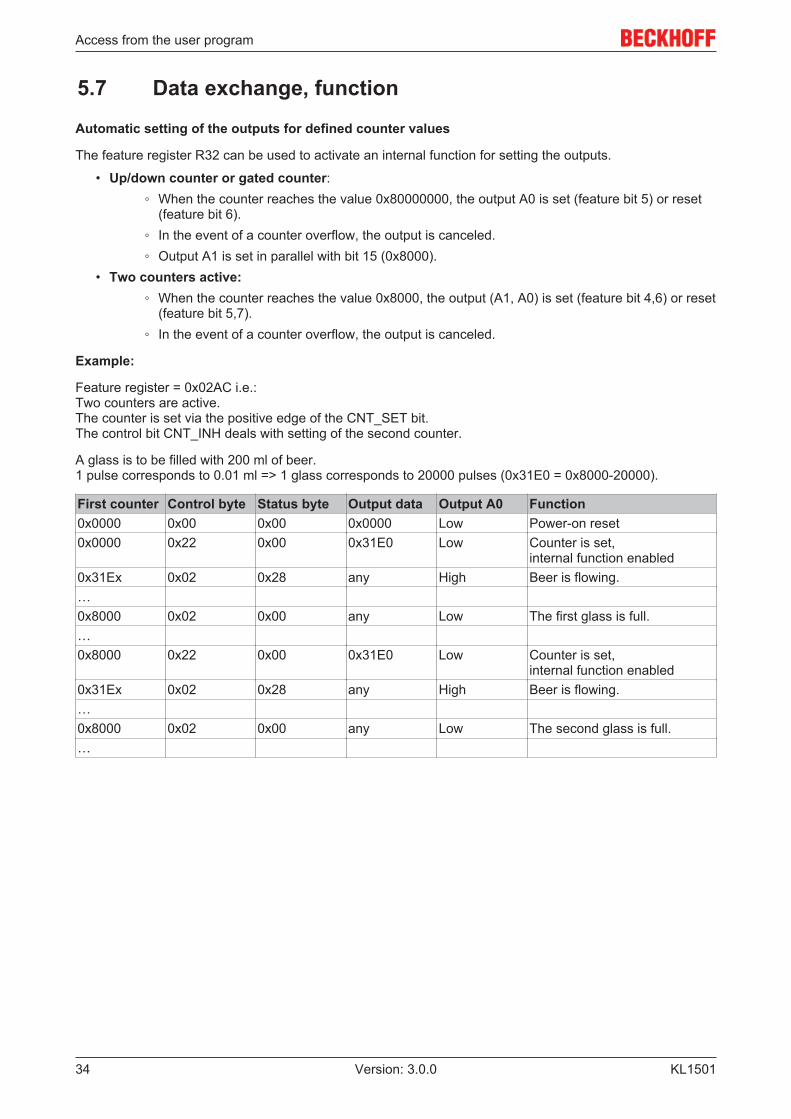
Automatic setting of the outputs for defined counter values
The feature register R32 can be used to activate an internal function for setting the outputs.
• Up/down counter or gated counter:◦ When the counter reaches the value 0x80000000, the output A0 is set (feature bit 5) or reset
(feature bit 6).◦ In the event of a counter overflow, the output is canceled.◦ Output A1 is set in parallel with bit 15 (0x8000).
• Two counters active:◦ When the counter reaches the value 0x8000, the output (A1, A0) is set (feature bit 4,6) or reset
(feature bit 5,7).◦ In the event of a counter overflow, the output is canceled.
Example:
Feature register = 0x02AC i.e.:Two counters are active.The counter is set via the positive edge of the CNT_SET bit.The control bit CNT_INH deals with setting of the second counter.
A glass is to be filled with 200 ml of beer.1 pulse corresponds to 0.01 ml => 1 glass corresponds to 20000 pulses (0x31E0 = 0x8000-20000).
First counter Control byte Status byte Output data Output A0 Function0x0000 0x00 0x00 0x0000 Low Power-on reset0x0000 0x22 0x00 0x31E0 Low Counter is set,
internal function enabled0x31Ex 0x02 0x28 any High Beer is flowing.…0x8000 0x02 0x00 any Low The first glass is full.…0x8000 0x22 0x00 0x31E0 Low Counter is set,
internal function enabled0x31Ex 0x02 0x28 any High Beer is flowing.…0x8000 0x02 0x00 any Low The second glass is full.…
TwinCAT
KL1501 35Version: 3.0.0
6 TwinCAT
PLC and Motion Control on the PC
TwinCAT - The Windows Control and Automation Technology
The TwinCAT automation software converts any compatible PC into a real-time controller with multi-PLC, NCaxis control, programming environment and operating station. TwinCAT replaces conventional PLC and NCcontrollers as well as operating devices:
• open, compatible PC hardware• Embedding of IEC 61131-3 software PLC, software NC and software CNC in Windows NT/2000/XP,
NT/XP Embedded, CE• Programming and runtime systems optionally together on one PC or separated• Connection to all common fieldbus systems• PC interfaces are supported• Data communication with user interfaces and other programs by means of open Microsoft standards
(OPC, OCX, DLL, etc.)
TwinCAT architecture
TwinCAT consists of runtime systems for real-time execution of control programs and developmentenvironments for programming, diagnosis and configuration. Any Windows programs, for instancevisualization programs or Office programs, can access TwinCAT data via Microsoft interfaces, or canexecute commands.
A practically oriented software solution
TwinCAT offers a precise time-base in which programs are executed with the highest deterministic features,independently of other processor tasks. The real-time load on a PC is set with TwinCAT: This achieves adefined operating behavior. TwinCAT displays the system load for running programs. A loading thresholdcan be set, in order to assure a defined computing capacity for the operating programs and for WindowsNT/2000/XP. If this threshold is exceeded, a system message is generated.
TwinCAT supports system diagnosis
The general use of hardware and software from the open PC world requires some checking: Unsuitablecomponents can upset the PC system. Beckhoff integrates a handy display of the real-time jitter in order toprovide administrators with a simple means of evaluating hardware and software. A system message duringoperation can draw attention to error states.

TwinCAT
KL150136 Version: 3.0.0
Start/stop behavior
Depending on the setting, TwinCAT is started and stopped manually or automatically. Since TwinCAT isintegrated into Windows NT/2000/XP as a service, an operator is not needed to start the system: switchingon is enough.
Restarting and data backup
When a program is started or restarted, TwinCAT loads programs and remanent data. To backup data, andto shut down Windows NT/2000/XP correctly, a UPS (uninterruptible power supply) is of great value.
TwinCAT and "Blue Screen"
The TwinCAT system can be configured such that real-time capability is maintained in the event of a BSOD(Blue-Screen-of-Death) operating system crash. Real-time tasks such as PLC and NC can thus continue torun and place the controlled process in a safe state. Ultimately, it is the decision of the programmer whetheror not to utilize this feature, bearing in mind that data or programs may already have been destroyed by theBSOD.
World-wide connection through message routing - "remote" connection is inherent to the system
According to the requirement for operating resources, the TwinCAT software devices can be distributed:TwinCAT PLC programs can be executed on PCs and on Beckhoff Bus Terminal controllers. A "messagerouter" manages and distributes all the messages, both in the system and via TCP/IP connections. PCsystems can be connected to one another by TCP/IP; Bus Terminal controllers are connected via serialinterfaces and fieldbus systems (EtherCAT, Lightbus, PROFIBUS DP, PROFINET, Interbus, CANopen,DeviceNet, RS232, RS485, Ethernet TCP/IP, Ethernet/IP).
World-wide access
Since standard TCP/IP services from Windows NT/2000/XP are used, this data exchange can take placeworldwide. The system offers scalable communication capacity and timeout periods for the monitoring ofcommunications. OPC provides a standardized means for accessing many different SCADA packets. TheSOAP (Simple Object Access Protocol) enables a connection between two computers to be established bymeans of an internet connection via standard HTTP. A TwinCAT component is available for this purpose.
Beckhoff Information System
Further information on the TwinCAT automation software can be found in the Beckhoff Information System.
The setup for installing the Beckhoff Information System is available to you on the BeckhoffProducts & Solutions DVD and on our website for download.
In addition, the online version of the Beckhoff Information System can be found at https://infosys.beckhoff.com.
6.1 Programming
TwinCAT libraries
See software documentation in the Beckhoff Information System.
TwinCAT 2: TwinCAT PLC Lib: I/O functions
TwinCAT 3: TwinCAT 3 PLC Lib: Tc2_IoFunctions
6.2 Function block FB_KL1501ConfigThe function block FB-KL1501Config can be used to configure the KL1501 terminal. A more detaileddescription can be found in the Beckhoff Information System:

TwinCAT
KL1501 37Version: 3.0.0
TwinCAT2: TwinCAT PLC Lib: I/O functions/Bus Terminal configuration
TwinCAT3: TwinCAT 3 PLC Lib:Tc2_I/O functions/Function blocks/Bus Terminal configuration

Appendix
KL150138 Version: 3.0.0
7 Appendix
7.1 Support and ServiceBeckhoff and their partners around the world offer comprehensive support and service, making available fastand competent assistance with all questions related to Beckhoff products and system solutions.
Beckhoff's branch offices and representatives
Please contact your Beckhoff branch office or representative for local support and service on Beckhoffproducts!
The addresses of Beckhoff's branch offices and representatives round the world can be found on her internetpages:http://www.beckhoff.com
You will also find further documentation for Beckhoff components there.
Beckhoff Headquarters
Beckhoff Automation GmbH & Co. KG
Huelshorstweg 2033415 VerlGermany
Phone: +49(0)5246/963-0Fax: +49(0)5246/963-198e-mail: [email protected]
Beckhoff Support
Support offers you comprehensive technical assistance, helping you not only with the application ofindividual Beckhoff products, but also with other, wide-ranging services:
• support• design, programming and commissioning of complex automation systems• and extensive training program for Beckhoff system components
Hotline: +49(0)5246/963-157Fax: +49(0)5246/963-9157e-mail: [email protected]
Beckhoff Service
The Beckhoff Service Center supports you in all matters of after-sales service:
• on-site service• repair service• spare parts service• hotline service
Hotline: +49(0)5246/963-460Fax: +49(0)5246/963-479e-mail: [email protected]
List of illustrations
KL1501 39Version: 3.0.0
List of illustrationsFig. 1 KL1501 ........................................................................................................................................ 7Fig. 2 KL1501 - LEDs ............................................................................................................................ 9Fig. 3 Attaching on mounting rail ........................................................................................................... 10Fig. 4 Disassembling of terminal............................................................................................................ 11Fig. 5 Power contact on left side............................................................................................................ 12Fig. 6 Standard wiring............................................................................................................................ 14Fig. 7 Pluggable wiring .......................................................................................................................... 14Fig. 8 High Density Terminals................................................................................................................ 14Fig. 9 Mounting a cable on a terminal connection ................................................................................. 15Fig. 10 KL1501 - Connection ................................................................................................................... 17Fig. 11 KS2000 configuration software.................................................................................................... 20Fig. 12 KL1501 - Mapping in the Lightbus Coupler ................................................................................. 22Fig. 13 KL1501 - Mapping in the Profibus Coupler.................................................................................. 22Fig. 14 KL1501 - Mapping in the Interbus Coupler .................................................................................. 23Fig. 15 Register mode control byte.......................................................................................................... 30