Documentaion of datalogger and arduino
12
ROLE OF DATA LOGGER AND SENSORS IN DEW AND RAIN WATER HARVESTING SYSTEM NEAR KHOTARA PART-1
-
Upload
thulasisarvan -
Category
Devices & Hardware
-
view
259 -
download
4
Transcript of Documentaion of datalogger and arduino
ROLE OF DATA LOGGER AND SENSORS
IN
DEW AND RAIN WATER HARVESTING SYSTEM NEAR KHOTARA
PART-1
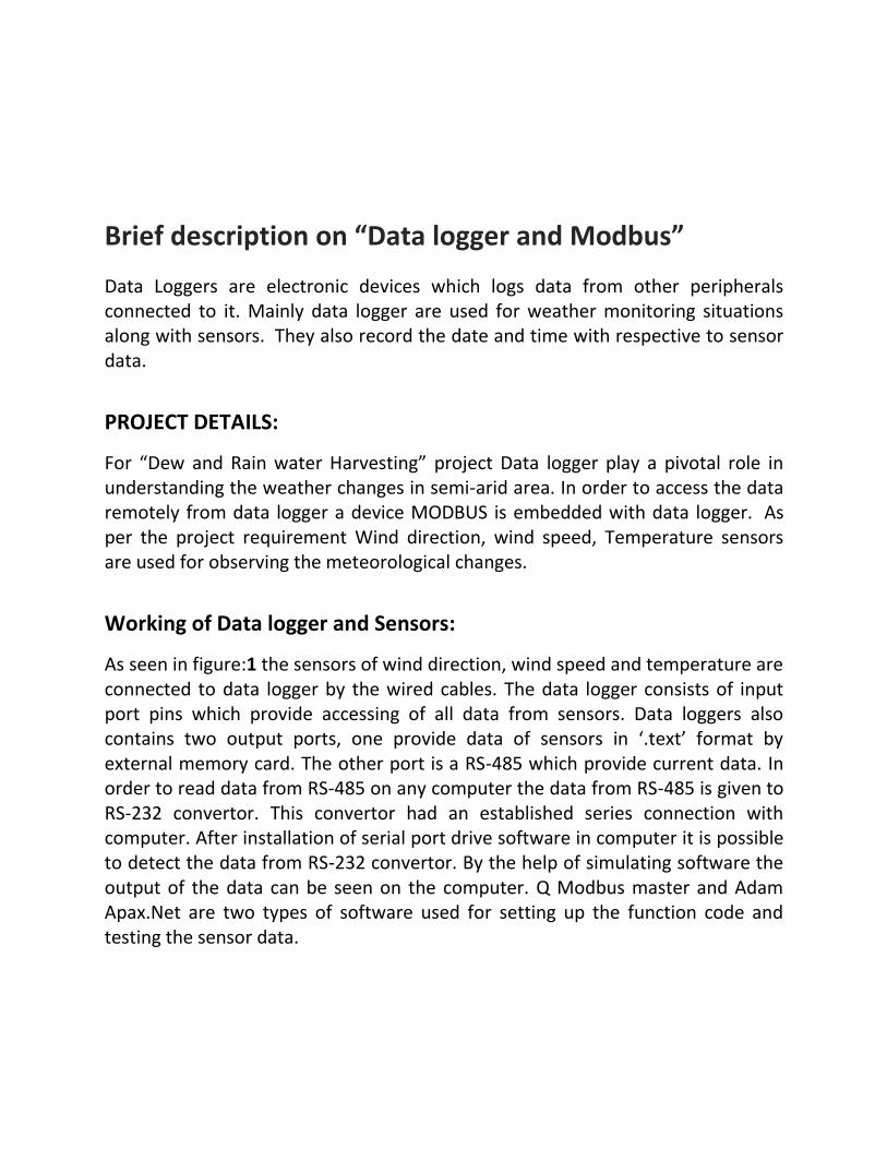
Brief description on “Data logger and Modbus”
Data Loggers are electronic devices which logs data from other peripherals connected to it. Mainly data logger are used for weather monitoring situations along with sensors. They also record the date and time with respective to sensor data.
PROJECT DETAILS:
For “Dew and Rain water Harvesting” project Data logger play a pivotal role in understanding the weather changes in semi-arid area. In order to access the data remotely from data logger a device MODBUS is embedded with data logger. As per the project requirement Wind direction, wind speed, Temperature sensors are used for observing the meteorological changes.
Working of Data logger and Sensors:
As seen in figure:1 the sensors of wind direction, wind speed and temperature are connected to data logger by the wired cables. The data logger consists of input port pins which provide accessing of all data from sensors. Data loggers also contains two output ports, one provide data of sensors in ‘.text’ format by external memory card. The other port is a RS-485 which provide current data. In order to read data from RS-485 on any computer the data from RS-485 is given to RS-232 convertor. This convertor had an established series connection with computer. After installation of serial port drive software in computer it is possible to detect the data from RS-232 convertor. By the help of simulating software the output of the data can be seen on the computer. Q Modbus master and Adam Apax.Net are two types of software used for setting up the function code and testing the sensor data.
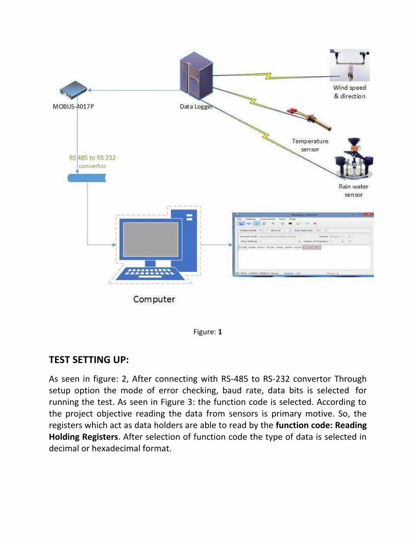
Figure: 1
TEST SETTING UP:
As seen in figure: 2, After connecting with RS-485 to RS-232 convertor Through setup option the mode of error checking, baud rate, data bits is selected for running the test. As seen in Figure 3: the function code is selected. According to the project objective reading the data from sensors is primary motive. So, the registers which act as data holders are able to read by the function code: Reading Holding Registers. After selection of function code the type of data is selected in decimal or hexadecimal format.
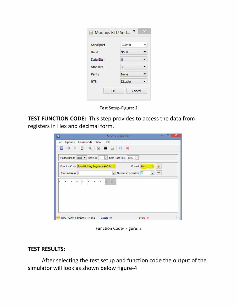
Test Setup-Figure: 2
TEST FUNCTION CODE: This step provides to access the data from registers in Hex and decimal form.
Function Code- Figure: 3
TEST RESULTS:
After selecting the test setup and function code the output of the simulator will look as shown below figure-4

TEST RESULT FIGURE: 4
While observing the test results we can find the data is in hexadecimal form and the number of the registers which means the sensors data can be seen serially. But there are 10-errors in the result that can be seen in right bottom of the screen shot. This is because the wrong selection of RTU mode. From Figure:2 we selected COM 4 but while selecting function code the setup is disturbed by re-plugin, at that moment the software selected the available COM 3 or COM 2. This leads to the error probability in the results.
After correcting the set-up code and function code the error is corrected by changing the sections. NOTE: This time the set-up code is detected the COM: 3 and type of data is selected decimal form. The results can be seen in the below figure: 5
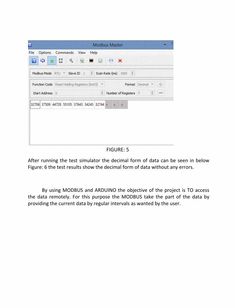
FIGURE: 5
After running the test simulator the decimal form of data can be seen in below Figure: 6 the test results show the decimal form of data without any errors.
By using MODBUS and ARDUINO the objective of the project is TO access the data remotely. For this purpose the MODBUS take the part of the data by providing the current data by regular intervals as wanted by the user.
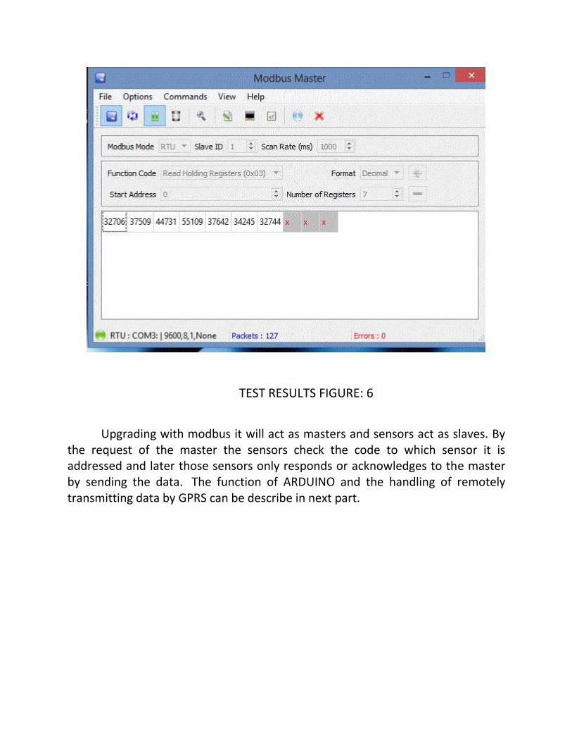
TEST RESULTS FIGURE: 6
Upgrading with modbus it will act as masters and sensors act as slaves. By the request of the master the sensors check the code to which sensor it is addressed and later those sensors only responds or acknowledges to the master by sending the data. The function of ARDUINO and the handling of remotely transmitting data by GPRS can be describe in next part.
PART-2

Transferring data from remote position:
From data logger to the board:
After the data has been logged into the data logger by the sensors. Modbus
protocol is used to retrieve and read data from the Data logger. The Data logger
acts as a slave and the modbus acts as ‘Master’. This master retrieves data by
reading the data logger registers and send them over to the outport port. The RS
connector from the Modbus is connected to the arduino board. Using a converter
the output data from RS port is converted to serial USB port. This port is
connected to the Arduino Board.
Inside the Arduino Board:
Using the modbus library and the source code is written to read the data. The
data travels over the Rs port to the convertor to the serial input of the arduino
board. The arduino board after receiving the data is analysed. The data is received
periodically depending upon the baud rate of the system. Using the predefined
Modbus library a code is written. This code would call the predefined functions
which would be able to read the incoming data from the modbus. The data is sent
to the GSM/GPRS shield which is connected to the arduino board through the Rx
and Tx pins of the arduino. The arduino acts as master and makes the shield work
as its slave.

On the GSM/GPRS shield:.
This GSM shield would have an onboard SIM card with GSM connectivity and
active an connection to the internet GPRS.It would draw power from the arduino
board and the communication with the arduino is done via the Rx and Tx pins.
Data through sms:
Using the ‘SMS’ library of the arduino IDE various advantages of the SMS service
can be taken. This SMS library has simple predefined functions to send and
receive SMSs to any number.
Using the SMS service:
The ways in which this SMS service can be used in our project are as follows:
a.) If the data is found to be crossing the safety limits(as predefined in the source
code) then an immediate SMS would be sent to the concerned person about the
emergency situation
b.) Another usage of this service would be sending SMS to the concerned person
when the input data indicates the faulty state of any sensor. The source could
would be able to rectify the particular sensor which is not working fine and
information about that particular sensor would be sent over.
Using the internet service:
The shield via the SIM card also connects to the Internet. After every specified
amount of time the data received from the logger is transmitted over GPRS
connection to the internet. After that has been landed on to the internet after
crossing the appropriate carrier’s APN the data is feeded to a website. The source
code includes the URL of an input feed through which the data is routed to the
appropriate server of the website. This data can be accessed and analysed from
the server by the concerned person.
Future Aims:
Future functionalities that can be implemented in the system is the functionality
of ‘instant status’. In this functionality anyone who has the number of the
onboard SIM card could ping the system through a SMS. The shield, using the SMS
class, would store the number of the receiver and would read the contents of the
SMS. If the contents of the SMS matches any of the predefined set of keywords
stored in arduino source code then the shield would react accordingly. After
reading the code it would switch to appropriate switch case and complete the
users requests by replying to the senders number with appropriate requested
data.