Document title - Home Page - Physics at...
80
Operator’s Handbook IPS120-10 Superconducting Magnet Power Supplies (120 amps, 10 volts) Issue 06 November 2000 File reference: CBL06-S.DOC Oxford Instruments Superconductivity Tubney Woods, Abingdon, Oxon, OX13 5QX, England Tel: +44 (0)1865 393 200 Fax: +44 (0)1865 393 333 E-mail:[email protected] www.oxford-instruments.com
-
Upload
nguyenduong -
Category
Documents
-
view
219 -
download
3
Transcript of Document title - Home Page - Physics at...

Operator’s Handbook
IPS120-10Superconducting Magnet Power Supplies
(120 amps, 10 volts)
Issue 06
November 2000
File reference: CBL06-S.DOC
Oxford Instruments
Superconductivity
Tubney Woods, Abingdon,
Oxon, OX13 5QX, England
Tel: +44 (0)1865 393 200
Fax: +44 (0)1865 393 333
E-mail:[email protected]
www.oxford-instruments.com

Contents
1 Introduction .............................................................................................................. 4
1.1 Use of this Manual...................................................................................... 4
1.2 Description of Equipment .......................................................................... 4
1.3 Warnings..................................................................................................... 4
1.4 Important Note........................................................................................... 4
2 Safety......................................................................................................................... 5
2.1 Protective Ground ...................................................................................... 5
2.2 Magnet Terminals....................................................................................... 5
2.3 Repair and Adjustment .............................................................................. 5
2.4 Safety Standards......................................................................................... 5
3 Installation ................................................................................................................ 6
3.1 System Grounding ...................................................................................... 6
3.2 Magnet Connections .................................................................................. 7
3.3 Serial Data Line Connection....................................................................... 7
3.4 The Oxford Instruments ISOBUS ................................................................ 8
3.5 GPIB (IEEE-488) Connection ....................................................................... 8
3.6 The GPIB to ISOBUS Gateway .................................................................... 9
3.7 Parallel Interface Connections ................................................................. 10
3.7.1 Safe Current Interlock ............................................................ 11
3.7.2 Auto-Run-Down...................................................................... 11
3.8 Analogue Interface Connections ............................................................. 11
3.9 Configuring the Power Supply for the Magnet...................................... 12
4 Local Operation ...................................................................................................... 13
4.1 Front Panel Controls................................................................................. 13
4.1.1 POWER .................................................................................... 13
4.1.2 ADJUST .................................................................................... 13
4.1.3 CONTROL................................................................................. 13
4.1.4 SWITCH HEATER ..................................................................... 14
4.1.5 SWEEP CONTROL .................................................................... 14
4.1.6 DISPLAY................................................................................... 16
4.2 Voltage Limiting....................................................................................... 19
4.3 Metering ................................................................................................... 20
4.4 First Time Operation................................................................................. 20
5 Remote Operation .................................................................................................. 22
5.1 Introduction.............................................................................................. 22
5.2 Communication Protocols ........................................................................ 22
5.3 Commands and Responses ....................................................................... 22
5.4 Numeric Parameters ................................................................................. 23
5.5 Use of the Oxford Instruments ISOBUS ................................................... 23
5.6 The GPIB Interface .................................................................................... 24
5.6.1 Sending Commands via the GPIB........................................... 25
5.6.2 Accepting Responses via the GPIB ......................................... 25
5.6.3 The Status Byte, Use of a Serial Poll ...................................... 25
5.6.4 Use of the Service Request Line ............................................. 26

5.6.5 Use of the Device Clear Function........................................... 26
5.6.6 Use of the Interface Clear (IFC) Function .............................. 26
5.6.7 Non-Implemented Features of the GPIB ............................... 27
5.6.8 Compatibility with IEEE-488.2................................................ 27
5.6.9 Use of the GPIB Interface as a GATEWAY to ISOBUS ........... 27
5.6.10 Writing a "Rugged" GPIB Control Program.......................... 28
6 Command Syntax .................................................................................................... 29
6.1 Monitor Commands.................................................................................. 29
6.2 Control Commands................................................................................... 34
6.3 System Commands.................................................................................... 37
7 Auto-Run-Down...................................................................................................... 39
8 Fault Conditions...................................................................................................... 40
8.1 Fault Index ................................................................................................ 40
8.2 Mains Failure ............................................................................................ 40
9 Test Mode................................................................................................................ 41
9.1 Entry to Test Mode................................................................................... 41
9.2 Test Menu ................................................................................................. 41
9.3 Test 00 Exit (and Storing Calibration Data) .......................................... 42
9.4 Test 01 Test Front Panel Lamps.............................................................. 42
9.5 Test 02 Test Front Panel Buttons ........................................................... 42
9.6 Test 03 Setting the GPIB address ........................................................... 43
9.7 Test 04 F (Front Panel Display) Menu ...................................................... 44
9.8 Test 05 PSU (Power Supply) Menu......................................................... 44
9.9 Test 06 Magnet System Configuration.................................................. 48
9.10 Test 07 SUP(superconducting magnet) Menu......................................... 50
10 Specification............................................................................................................ 54
11 Quick Reference Guide........................................................................................... 55
11.1 Front Panel Controls................................................................................. 55
11.2 Display Parameters ................................................................................... 58
12 Circuit Diagrams...................................................................................................... 59
Oxford Instruments Superconductivity Limited, November, 2000. All rights strictly reserved.

4
1 Introduction
1.1 Use of this ManualSections 1-4 provide essential information and should be read before operating the
instrument for the first time. The remainder of the manual provides more detail on
specific aspects and may be referred to as required.
1.2 Description of EquipmentThe polarity of the current in the power supply can be selected, allowing magnets to be
energised in a positive or negative direction. A separate output for a switch heater is
provided for magnets incorporating a superconducting switch. Remote computer control
of all power supply functions can be performed via RS232 and GPIB interfaces.
1.3 WarningsBefore you attempt to install or operate this equipment for the first time, please make
sure that you are aware of the precautions that you must take to ensure your own safety.
In particular please read the Safety section of this manual.
1.4 Important NoteThis manual is part of the product that you have bought. Please keep it for the whole life
of the product and make sure that you incorporate any amendments which might be sent
to you. If you sell or give away the product to someone else please give them the manual
too.

5
2 SafetyThe following general safety precautions must be observed during the operation, service
and repair of this instrument.
2.1 Protective GroundTo minimise shock hazard the instrument must be connected to an electrical ground. The
ground wire (green/yellow) in the instrument AC power cable must be connected to the
installation electrical ground system. Do not disconnect the protective ground inside or
outside the instrument.
There must always be a ground connection between the power supply and the cryostat, a
suitable wire is included in the magnet current leads.
2.2 Magnet TerminalsUnder no circumstances should the magnet cable be disconnected from the power supply
or the magnet while current is flowing in the magnet. This may cause dangerously high
voltages to appear on the magnet cables or terminals.
2.3 Repair and AdjustmentSome internal adjustments can be made to the power supply. Although Oxford
Instruments does not encourage you to make these adjustments we try to supply you with
enough information to allow you to do it safely. Disconnect the AC power supply before
you remove the covers or fuses, because dangerous voltages are accessible on the circuit
board and other components. It is not sufficient to switch off the front panel power
switch.
Some fault finding operations can only be carried out with power connected to the
instrument. If you have to reconnect the AC power supply with the protective covers
removed you must remember that you are putting your life at risk. You should only do
this type of work if you are suitably qualified and sufficiently skilled to understand all the
risks you are taking.
Fault finding within the large switch-mode power supply (SMPS) is not recommended.
This is a specialist unit and should be returned to the factory for replacement or repair.
2.4 Safety StandardsThis equipment is designed to meet the following safety requirement:
IEC1010-1 with Amendment 1: 1992
“Safety requirements for electrical equipment for measurement, control and laboratory
use”.

6
3 Installation
3.1 System GroundingThe power supply and magnet will frequently be used in a system with other test and
monitoring instruments. It is important for the user to know how the power supply is
connected to ground (to mains earth or chassis) in order to ensure that all interfaces are
compatible. Incorrect grounding could damage the power supply or other instruments.
The metal case (chassis) of the power supply is connected to the earth wire of the mains
cable. This connection is never broken, for safety reasons.
The signal returns of the computer interfaces (RS232 and IEEE) are joined to the MAGNET -
VE busbar. This done inside the power supply and cannot be changed, else the power
supply would not operate correctly.
The signal returns of the Parallel and Analogue Interfaces are also joined to the MAGNET -
VE busbar inside the power supply, and so also is the +ve terminal of the switch heater
output.
The power supply is normally shipped from the factory with the MAGNET -VE busbar
linked to chassis. This is done using a solid metal ground link which is fitted outside the
unit, underneath the MAGNET -VE busbar. This link can be seen from the rear of the
power supply. The user should normally operate the power supply with the ground link
fitted.
When the ground link is fitted, the Computer, Parallel and Analogue interface returns are
all grounded to chassis. The ground link provides an important function - it will protect
the power supply from damage if there is a fault inside the cryostat with an arc between
the magnet and the cryostat. (For safety reasons it is also important that the cryostat has
a high-current earth wire connected to the earth terminal on the rear of the power
supply.)
In some installations it is necessary for the power supply output to be floating, not linked
to ground. This occurs, for example, when more than one power supply is used to operate
coils which are connected in series. The ground link may then be removed from the
MAGNET -VE busbar. However, it is important to remember that the signal interface
returns are internally joined to MAGNET -VE and that it may not be possible to connect a
computer or other grounded instruments directly to the power supply without risking
damage. In this situation, optically isolated interfaces are recommended, such as the
Oxford Instruments ISOBUS section 3.4.
If the ground link is removed, the maximum voltage between chassis and either output
busbar must never exceed +/- 50V. This limit is due to noise filter capacitors fitted
between output and chassis.
It should be recognised that in the (rare) event of a severe magnet fault, there is more risk
of damage to the power supply when the ground link is not fitted.

7
3.2 Magnet ConnectionsConnections to the main magnet current terminals are made via the busbar bolts on the
rear panel. A suitable high current cable (normally supplied with the magnet), should be
used.
The magnet cable should include an earth wire from the cryostat. Connect this to the
earth terminal on the rear panel of the power supply.
When making the connections, the power supply should be switched off to ensure that
the output voltage is zero. Current polarity is defined as positive when current flows out
of the MAGNET +VE busbar and returns to MAGNET -VE.
Danger On no account should these connections be made or broken unless both the
voltmeter and the ammeter on the power supply are at zero
The small red and black terminals on the rear panel provide connections to the heater of
the superconducting switch on the magnet, if fitted.
3.3 Serial Data Line ConnectionAn RS232C bi-directional serial data link from a computer may be connected via the 25
way D-socket labelled RS232 on the rear panel. The unit is configured as a Data
Communication Equipment (DCE) and may be connected directly to a computer or a data
terminal, configured as a Data Termination Equipment (DTE). If the power supply is to be
connected to a computer which is itself configured as a DCE, pins 2 and 3 should be
swapped in the interconnecting cable. For computers fitted with a 9 way D plug for
RS232, (AT style COM port), a standard "AT lead" fitted with a 9 way socket and a 25 way
plug is required.
Pin connections at the RS232 socket are:
Pin Name Notes
1 FG Linked to Chassis Ground in power supply
2 TD Received Data (From Computer)
3 RD Transmitted Data (To Computer)
4 RTS Linked to 5
5 CTS Linked to 4
6 DSR +5V when unit is powered up
7 GND Signal Ground
8 DCD +5V when unit is powered up
All other pins are open circuit.
The power supply does not require signals to be present on any of the "modem control"
lines, RTS or DTR (pin 20). In other words, the power supply only requires pins 2,3 and 7 to
be connected to a computer. However, to ensure maximum compatibility with any
requirement of the computer, RTS is looped back as CTS and logic high levels are returned
on DSR and DCD.

8
Voltage levels for the transmitted and received data are:
Transmitted Data High > +5.5V
Transmitted Data Low < -5.5V
Received Data High Threshold < +2.6V
Received Data Low Threshold > +1.4V
Max. Rx Input Voltage +/- 30V
Data protocols are:
Handshake None required
Baud Rate 9600
Tx Start Bits 1
Tx Data Bits 8
Tx Stop Bits 2
Rx Start Bits 1
Rx Data Bits 8
Rx Stop Bits 1 or more
For normal ASCII exchanges the 8th data bit is treated as a parity bit. It is always set to
"0" on transmitted data. It is ignored on received data.
3.4 The Oxford Instruments ISOBUSA unique feature of this power supply and other Oxford Instruments products, is the
ability to connect a number of instruments simultaneously, to a single RS232 port on a
computer and to control each one independently. This is done by means of an ISOBUS
cable which carries a single MASTER connector (25-way D socket) and up to eight, daisy-
chained SLAVE connectors (25-way D plugs). Each slave connector incorporates full optical
isolation so that the slaves are all isolated from the master and from each other. The
slaves connectors draw their power from the individual instruments, via the DCD signal on
pin 8. The master connector may draw its power from either DTR or RTS signals from the
computer.
To use ISOBUS, a special communication protocol is required, which is part of the
command structure of Oxford Instruments products and is described in section 5.5.
3.5 GPIB (IEEE-488) ConnectionConnections to the GPIB are made via a standard 24 way GPIB connector on the rear
panel. Assignment of the connector pins conforms to the standard IEEE-488.1.
Connections should be made using a standard GPIB cable.
Caution GPIB connections should never be made or broken whilst the monitor or any of the
instruments connected to the Bus are powered up. Failure to observe this precaution can
result in damage to one or more instruments.

9
The GPIB interface complies fully with IEEE-488.1-1987 as a talker/listener, able to
generate service requests and respond to serial poll and device clear commands. It does
not support parallel polling and has no trigger function. Open collector drivers are used
on the bus lines so it does not prevent parallel polling of other devices on the bus. Its
complete GPIB capability is specified by the Capability Identification Codes:-
SH1 AH1 T6 L4 SR1 RL0 PP0 DC1 DT0 C0 E1
Two lamps are fitted to the rear panel below the GPIB connector, to assist in diagnosing
any GPIB communication problems. The RED lamp lights whenever the power supply is
addressed to TALK and the GREEN lamp lights whenever it is addressed to LISTEN. The
behaviour of the lamps is very dependent on the GPIB monitor in use. Some controllers
un-address an instrument at the end of any transaction, in which case the lamps will just
blink on for each transaction. Others leave instruments addressed between transactions in
which case one or other lamp may remain lit depending on whether the power supply was
last addressed to talk or to listen.
Before any communication can occur, the power supply must be given a unique GPIB
address. By default, the power supply is supplied with its address set to 25. If this address
is already in use by another instrument on the bus, it can be changed from the front panel
via the Test Mode. This is described in section 9.6.
3.6 The GPIB to ISOBUS GatewayThe power supply has the ability to act as a GATEWAY to an ISOBUS cable, allowing other
instruments to be linked to the GPIB without themselves requiring GPIB interfaces. This
can enable other Oxford Instruments' products, for which an internal GPIB interface is not
available, to be linked. It offers the additional advantage of optical isolation between
these instruments and the GPIB.
To use the gateway, all that is required is GATEWAY MASTER ADAPTOR. This allows the
25 way ISOBUS MASTER socket to be linked to the 25 way RS232 socket on the power
supply. The adaptor is a symmetrical 25-way plug to 25-way plug link, with pin
connections as shown below.
Beware of using 25-way plug to 25-way plug adaptors, sold as "DCE-linkers" by some
suppliers. Several different conventions exist for these, not all of which will work as a
Gateway Master Adaptor. The connections required are given in the table below. A
Gateway Master Adaptor providing these connections may be obtained from Oxford
Instruments.
25 WAY PLUG 25 WAY PLUG
1 1
2 3
3 2
7 7
6 4
4 6

10
Note that the connections are symmetrical and the adaptor may be plugged in either way
round.
The necessary protocols for the use of a power supply as a Gateway Master are described
in section 5.6.9.
3.7 Parallel Interface ConnectionsThe parallel interface port is a 15 way D-type connector on the rear panel, marked
"PARALLEL I/O" (which corresponds to SK2 on diagram CBL1202 sheet 2/3). It is a digital
interface and provides three separate functions.
1. an input signal to force a superconducting magnet to de-energise.
2. an output confirming the output current is within a defined range.
3. several uncommitted input and output lines for computer control. (3 input, 7 output,
see section Error! Reference source not found.)
The outputs are open-collector transistors (specification as for ULN2803A) and can sink up
to 500 mA from a supply of up to 25 volt maximum. When driving an inductive load, it is
recommended that a diode is connected across the load to absorb the stored energy.
For low power loads, current may be drawn directly from pin 15, which is connected via a
diode and fuse, to the internal unregulated 11 volt line. A maximum total current of
500mA may be drawn from this source.
The input lines on the parallel interface socket are suitable for either TTL level inputs (74
series, Transistor Transistor Logic) or contact closures to +5V. The input device is a
74HC244 and 100 kohm pull-down resistors to 0V are fitted. Pin connections at this socket
are:-
Pin Title Function
1 Output Bit 0 (spare)
9 Output Bit 1 (spare)
2 Output Bit 2 (spare)
10 Output Bit 3 (spare)
3 Output Bit 4 (spare)
11 Output Bit 5 (spare)
4 Output Bit 6 (spare)
12 Output Bit 7 (Safe Current Interlock)
5 Input K4 (spare)
13 Input K5 (spare)
6 Input K6 (spare)
14 Input K7 (Auto-Run-Down)
7 +5V
15 +11V unregulated. (Driver Protection)
8 0V

11
3.7.1 Safe Current InterlockThe safe current interlock is provided for users who require hardware confirmation that
the measured power supply current is within a safe current range. The upper and lower
current limits are set by the user, see section 9.10.
The "safe" condition is signalled by pin 12. If the current is "safe", the associated output
transistor will sink current, otherwise it will be high-impedance. A recommended interlock
circuit would consist of approximately 10 mA being drawn from pin 7 (at +5V) via an opto-
coupler.
The safe-current status can also be read using the serial data "X" command. However it is
not indicated on the front panel.
3.7.2 Auto-Run-DownAuto-run-down will automatically de-energise a magnet system. The function is described
in section 7.
To activate auto-run-down, pin 14 should be taken to logic 1 (+5V) relative to pin 8 (0V).
The recommended means by which to achieve this is by galvanically isolated contact-
closure (for example a relay) between pins 7 and 14.
For example, low helium level can trigger an auto-run-down by using an Oxford
Instruments ILM200 or HLM2 helium level meter. These meters contain relays which
change state when the helium level drops below a user setable level.
In the case of the ILM200, connections should be made to a pair of terminals inside the
ILM200 marked "COM" and "N/O".
In the case of the HLM2, connections should be made to a pair of terminals on the rear
panel, marked "COM" and "LOW".
Refer to the relevant level meter manual for further details.
3.8 Analogue Interface ConnectionsThe analogue interface port is a 9 way D-type connector on the rear panel, marked
"ANALOGUE I/O" (see diagram CBL2902 sheet 3/3 and PL102 on CBL5302 sheet 1/7). It
provides for analogue monitoring of power supply voltage and current and a modulation
input which allows the magnet current to be adjusted slightly by means of an analogue
control voltage or signal.

12
Pin connections at this socket are:
Pin Function
1 test use only
6 test use only
2 Current Shunt
7 Current Shunt return
3 Current Monitor
8 Current Monitor return
4 Voltage Monitor
9 Voltage Monitor return
5 Not connected
All of the return pins are internally connected by 1 kohm resistors to the same 0V as the
digital interfaces.
3.9 Configuring the Power Supply for theMagnet
If the power supply is provided as part of a magnet system, then values such as the correct
ratio of amps to tesla will have been loaded at the factory. However if the power supply
is shipped on its own, then certain parameters should be set.
All the configurable parameters are accessed through “test mode”, see section 9. There
are many parameters that may be set but the most important are listed below:-
Test 06 Magnet System Configuration. typically set to:
0 if there is no persistent switch fitted to the magnet.
1 if there is a persistent switch fitted to the magnet.
Test 07 Superconducting Magnet System.
S 01 Define amps / tesla.
S 02 Define power supply current limit.
S 11 Define magnet inductance.
S 15 Define switch heater current.

13
4 Local Operation
4.1 Front Panel ControlsThe operating controls are located on the front panel and are grouped together in
logically related boxes.
4.1.1 POWERThe main ON/OFF switch.
4.1.2 ADJUSTThe red RAISE and LOWER buttons are used to adjust a parameter. They have no effect on
their own but are always used in conjunction with one of the other buttons. Whenever a
parameter is being adjusted, its value is shown on the main display. Setting a value
involves pressing RAISE or LOWER until the required value is shown.
Operation of the RAISE and LOWER controls has been designed to allow large changes to
be made relatively quickly whilst at the same time enabling any value to be set exactly.
Pressing RAISE or LOWER briefly will cause the value to change by one digit. If the button
is held in, the last figure will start to change at about 5 units per second. After 2 seconds,
an approximately 10-fold increase in rate will occur, followed after another 2 seconds by a
further rate increase and so on. Altogether there are 6 different rates. Whenever RAISE
or LOWER is released, the next lower speed will be selected. This allows the user to
"home-in" on the required value most ergonomically.
4.1.3 CONTROLControl of the instrument may either be LOCAL from the front panel, or REMOTE via the
RS232 or GPIB interface. The LOC/REM button may be used to switch between LOCAL and
REMOTE. A third mode, Auto-Run-Down, is selectable via a socket on the rear panel, see
section 7.
When LOCK is lit, the instrument is locked into either local or remote control and the
LOC/REM button has no effect. At power up, it is locked in LOCAL, since at that time the
instrument has no way of knowing whether there is a computer connected to a digital
interface.
When the instrument is in REMOTE but not LOCKed, many of the front panel controls are
inoperative. Those controls which only affect the display, will still work but those which
could change the operation of the instrument are disabled.
When in REMOTE and LOCKed, the front panel is completely inoperative.
Auto-Run-Down locks out both LOCAL and REMOTE control. This state is indicated when
the "control" lights are flashing, see section 7.

14
4.1.4 SWITCH HEATERThis controls the heater supply for a superconducting switch on the magnet (if fitted). The
SELECT and CONFIRM lamps together indicate that the heater is on and the
superconducting switch is open, allowing the magnet to be energised. When the lamps
are off, the heater is un-powered and the superconducting switch is closed.
The SELECT lamp indicates the selected state of the switch heater and the CONFIRM lamp
shows when current is actually flowing in the heater circuit. CONFIRM detects a heater
current of approximately 5 milliamp or more. If SELECT is on and CONFIRM is off then
check that the switch heater leads are correctly connected.
The associated button allows the heater to be switched on and off. This button will only
function when the output current is stable, it is disabled whilst the output is sweeping.
Please note, It is usually necessary to wait several seconds after operating the button
before the superconducting switch changes state.
In order to prevent inadvertent damage to the magnet system, the switch heater will only
turn on if the power supply current matches the 'persistent magnet current' in both
magnitude and polarity (+/- zero amps are considered equal). The 'persistent magnet
current' is recorded as the current in the power supply when the magnet was last put
persistent. The record is updated whenever the switch heater is de-energised or if voltage
limiting occurs.
If the 'persistent magnet current' does not match the power supply current then the
'persistent magnet current' is displayed for as long as the switch heater button is
depressed. This safety feature gives a warning that the magnet system could be damaged
if the switch is opened. The operator should change the power supply current to match
the 'persistent magnet current' before attempting to energise the switch heater. If the
operator is confident that no damage will be done, then the safety feature can be
overridden by holding down the switch heater button for a period of four seconds after
which the switch heater is energised and the display reverts to displaying the power
supply current.
The current flowing through the switch heater may be adjusted to suit different switches
by setting a parameter in test mode (see section 9.10). If the power supply was supplied
with a magnet, the switch heater current will have been set to an optimum value at the
factory. The current is normally set to the minimum value at which the switch will open
reliably after 10-15 seconds.
4.1.5 SWEEP CONTROLHOLD, GOTO ZERO and GOTO SET buttons may be used to control the power supply
output current. Three lamps indicate which state is selected. A fourth state, clamped, is
possible and is indicated in the DISPLAY box along with other lamps that show when the
power supply is not in normal sweep mode.
HOLDHOLDHOLDHOLD
Unclamping a magnet. The clamped state can only be left by pressing HOLD. The
output clamp relays open and the magnet is connected to the power electronics.

15
Stopping a sweep. The power supply output current will remain at the same value
indefinitely. This extends into the voltage limiting mechanism, which is inhibited while
the HOLD button is pressed, see section 4.2.
A number of secondary functions are performed by HOLD, these are:-
i) The “Hot” and “Quenched” states are cleared.
ii) With a finger on HOLD, pressing SET POINT will cause the last recorded "Trip
Current" or "Trip Field" to be displayed. See section 4.2.
iii) With a finger on HOLD, pressing RAISE or LOWER will cause "FASt" or "SLO" to
be displayed and toggles between two maximum magnet sweep rate profiles.
FASt is the power up state and is restored whenever the power supply is
clamped. SLO is an alternative set of maximum sweep rates. There is no
significance in the two names, they only serve to distinguish the profiles. The
limiting rates are variables, see section 9.10.
GOTO ZEROGOTO ZEROGOTO ZEROGOTO ZERO
Causes a sweep towards zero current or field.
GOTO SETGOTO SETGOTO SETGOTO SET
Causes the power supply to sweep towards the set point current or field.
Sweep Mode and Immediate Mode
The sweep can proceed in one of two modes, "sweep mode" and "immediate mode" the
power supply automatically makes this decision depending on what load the power supply
is connected to. There are three possible loads:-
i) There is no superconducting switch fitted to the magnet. All power supply
current must pass through the magnet. The sweep proceeds in "sweep mode".
ii) There is a superconducting switch fitted but it is "open", the magnet is non-
persistent. Changes in the power supply current will all pass through the
magnet. The sweep proceeds in "sweep mode".
iii) The magnet is persistent because the superconducting switch has been closed.
Changes in the power supply current will all pass through the leads and
persistent switch only, not the magnet. The sweep proceeds in "immediate
mode".
The power supply knows if there is a switch fitted because of a flag set in the
"Configuration", see section 9.9. If there is a switch fitted, the state is determined by the
state of the switch heater; if the heater is on then the switch is "open", if the heater is off
then the switch is "closed".

16
The immediate mode sweep rate is fast, the default setting is from zero to full rated
current in 30 seconds, but this can be modified, see section 9.10. The sweep mode rate
will be that defined by the SET RATE button in the "DISPLAY" box unless the rate exceeds
and is limited by the maximum magnet sweep rate, see RATE LIMITING, explained later in
this section.
Note That if voltage limiting should occur at any point, the power supply will "catch" the
magnet and drop the power supply into the HOLD state, see section 4.2.
4.1.6 DISPLAYThe four lamps on the right of the display indicate deviations from the normal sweep
modes.
OUTPUT CLAMPEDOUTPUT CLAMPEDOUTPUT CLAMPEDOUTPUT CLAMPED
At switch on, the power supply is in a clamped state, and the OUTPUT CLAMPED lamp is
on. This is a "safe" state for a superconducting magnet, for example in an emergency it
can be used to run a magnet to zero, although as the stored energy of the magnet is
dissipated only by the lead resistance this is a rather slow method for de-energising a
magnet.
When the power supply is clamped, HOLD is the only state that can be entered.
PERSISTENT MODEPERSISTENT MODEPERSISTENT MODEPERSISTENT MODE
A superconducting magnet is put into persistent mode by closing the superconducting (or
persistent) switch which is fitted in parallel with the windings to complete the
superconducting circuit. The power supply current is then decreased to zero, so that all of
the magnet current flows through the switch.
This lamp indicates that the power supply lead current is zero, that the magnet is
persistent, and that the current in the magnet is non-zero. If there is zero current in the
magnet or the magnet is not persistent, then the lamp will not light. To discover the
current (or field) in a persistent magnet, press the MAGNET STATUS button.
SWEEP LIMITINGSWEEP LIMITINGSWEEP LIMITINGSWEEP LIMITING
This lamp indicates that the power supply output current is no longer being swept at the
rate defined by SET RATE but is under the control of a pre-set software limit, the
maximum magnet sweep rate. As the power supply only tries to sweep at the SET RATE
when looking at a magnet, this warning lamp should not light when driving current into a
superconducting switch.
Software sweep rate limits are sometimes installed at the factory for one of two reasons.
Firstly to protect a magnet from damage caused by sweeping it too fast or secondly to
prevent the power supply from being swept so fast as to touch the voltage limits (see
section 4.2). To change a limit see Sup 05 to Sup 09 in section 9.10.
QUENCHQUENCHQUENCHQUENCH
Indicates that the power supply has detected a sudden decrease in the output current.
This is a very unusual event and should it occur it is quite likely to be caused by a magnet
quench.

17
The threshold at which a quench is triggered depends on the magnet inductance. The
inductance can be adjusted by the user, see section 9.10. If the inductance is set too low,
the power supply will not detect a quenching magnet. If the inductance is set too high,
then a quench may be falsely triggered by normal operation.
A magnet quenches when part of the windings goes normal, or resistive. the energy
dissipated by the current flowing through this resistive part of the coil generates heat.
The heat usually causes the normal region to propagate rapidly through the whole
magnet.
For some magnets there is a possibility that a small winding (for example a cancellation
coil) may quench but not the bulk of the magnet, the small part absorbs most of the
magnet's stored energy and causes damage to the wire. Also, damage may occur to a
persistent magnet switch if after the quench the power supply outputs a large voltage
which heats up the switch while there is no liquid helium left to cool it.
For these reasons a "QUENCH" will cause the power supply to go to zero amps +1V.
About a minute after the magnet has settled at zero current, the power supply will clamp
the output and turn off the switch heater. When a quench is detected, the power supply
current will be recorded as the "Trip Current". To display the trip current, press and hold
the MAGNET STATUS (or HOLD) button and then press the SET POINT button.
To clear the QUENCH state and regain control at any time, the operator should press the
HOLD button.
Numeric DisplayNumeric DisplayNumeric DisplayNumeric Display
The numeric display normally indicates the delivered current in amps or the equivalent
field in tesla. Provided the supply is not voltage limiting this will give an accurate
indication of the actual power supply output.
When the power supply is in voltage limit mode (see section 4.2) the display will flash to
warn the operator that the number displayed is the target current or field rather than the
actual output. Under these conditions the analogue meter on the front panel indicates
the actual current.
The display may be switched to show other parameters. These are displayed whilst the
appropriate button is pressed. As soon as it is released the normal display returns. Whilst
SET POINT or SET RATE are pressed, RAISE and LOWER may be used to adjust the
parameter concerned, provided the unit is in LOCAL control.
"Hot" Message"Hot" Message"Hot" Message"Hot" Message
It is possible that the display may read "Hot" instead of a number, this indicates that the
transistor bank has overheated. The "Hot" state will cause the power supply to clamp.
The power supply should be left to cool with the power still on (thus powering the fans).
Pressing the HOLD button will restore normal operation but only if the overheated part
has cooled down.

18
VOLTS / AMPS / TESLAVOLTS / AMPS / TESLAVOLTS / AMPS / TESLAVOLTS / AMPS / TESLA
The units of the displayed parameter are indicated by these three lamps. In the case of
SET RATE, the units are amps/minute or tesla/minute. Please note that the amps/tesla
coefficient must be correctly set for the magnet. If the power supply was supplied with a
magnet, then the coefficient was set at the factory.
OUTPUT VOLTSOUTPUT VOLTSOUTPUT VOLTSOUTPUT VOLTS
The voltage across the (inductive) magnet is proportional to the rate of change of current,
so depends on the magnitude and sign of the sweep rate. The displayed voltage includes
the voltage drop due to the magnet cables, proportional to current and typically 1 volt at
full output current.
CURRENT / FIELDCURRENT / FIELDCURRENT / FIELDCURRENT / FIELD
Causes the display to toggle between displaying the various parameters in amps or an
equivalent number of tesla. The relationship between current and field is a linear one,
the conversion ratio depends on the magnet and will have been set at the factory. To
change the ratio see section 9.10.
MAGNET STATUSMAGNET STATUSMAGNET STATUSMAGNET STATUS
Press this button and the power supply will display the current (or field) that the power
supply believes to be in the magnet.
In the case of an magnet that has not been fitted with a persistent switch the display will
not change. If the magnet does have a persistent switch but it is 'open' then the display
will not change. If however the persistent switch is 'closed' then the display will change to
display the current (or field) in the magnet when it was last put persistent.
With a finger on MAGNET STATUS, pressing SET POINT will cause the last recorded "Trip
Current" or "Trip Field" to be displayed. See section 4.2.
SET RATESET RATESET RATESET RATE
Displays the sweep rate in amps per minute or the equivalent tesla per minute. Whilst
sweeping, the SET RATE may exceed the maximum magnet sweep rate, in which case the
sweep rate will be limited and SWEEP LIMITING will be illuminated (refer to page 16). At
very high sweep rates the power supply output voltage may be insufficient to enable a
magnet to follow the sweep and the power supply will voltage limit, see section 4.2.
Note that the SET RATE is only observed when in sweep mode (the power supply believes
it is driving a magnet). If a superconducting switch is fitted and it is persistent, the sweep
is in immediate mode and is at the rate limit e.g. 30 seconds from zero to full current, or
less if the limit has been reduced, see section 9.10.
SET POINTSET POINTSET POINTSET POINT
Displays the target point for a sweep either as current or the equivalent field. Using RAISE
and LOWER it may be adjusted between 0 and full current, or 0 and the maximum magnet
current if a current limit has been installed, see section 9.10.
Whilst holding the SET POINT button, the target polarity can be toggled by the CHANGE
POLARITY button. The sign of SET POINT corresponds to the polarity of the target current.

19
With a finger on HOLD, pressing (display) SET POINT will cause the last recorded "Trip
Current" or "Trip Field" to be displayed, see section 4.2.
CHANGE POLARITYCHANGE POLARITYCHANGE POLARITYCHANGE POLARITY
The CHANGE POLARITY button has no effect when pressed on its own. However, while
SET POINT is depressed, pressing CHANGE POLARITY causes the polarity of the set point
current, or field, to toggle. The sign of the set point corresponds to the polarity of the
target current.
4.2 Voltage LimitingVoltage limiting can result from several causes e.g. a magnet being swept too fast, a
magnet quench or a superconducting switch breaking open.
Two voltage limits exist, fast hardware voltage limits (usually set to +/- 10 or +/-20 volts),
and slow software voltage limits. In normal use, the power supply output voltage will stay
within both sets of limits. However, if a limit is exceeded the power supply will go into
"catch" mode and stabilise the magnet system by matching the power supply current to
the magnet current. Whilst voltage limiting the display will flash as there may be a
discrepancy between the actual power supply output current and the displayed current.
Pressing the HOLD button will temporarily disable voltage limiting.
When the power supply first reaches a voltage limit, the power supply output is recorded
as the trip current, displayed by pressing MAGNET STATUS (or HOLD) and SET POINT (see
above). When a magnet has been "caught" the power supply is left in its HOLD state and
the (persistent) magnet current is updated (thus an accurate record of magnet current is
kept even if a superconducting switch closes at a current different from that when the
operator last turned off the switch heater).
For some (unswitched) magnet systems, the catch mechanism is accidentally triggered at
the beginning (or end) of a fast sweep. This transient or voltage overshoot is due to a low
frequency resonance between the magnet and the output capacitors of the power supply.
The catch mechanism can be told to ignore the first 2 seconds of voltage limiting, it will
only trigger if voltage limiting persists for longer than this time. To make the power
supply ignore transients, a switch must be set in the “configuration”, see section 9.9.
Software voltage limits are not commonly used. They are intended to protect magnets at
the end of long or very resistive leads. The power supply continuously monitors the
magnet lead resistance and calculates the voltage drop across them, subtracting this
voltage from the voltage measured at the power supply terminals results in the voltage at
the magnet.
If the software voltage limits are required, they should be set to be just below the voltage
of the magnet protection network, the power supply firmware will then make allowance
for the voltage drop across the leads. If the power supply exceeds this limit then some of
the current must be flowing in the protection circuit, if the condition persists for more
than a pre-set period (e.g. 2 seconds), the magnet will be "caught".
20
4.3 MeteringAnalogue meters are mounted on the front panel and will indicate the actual output
Current and Voltage of the power supply at all times, even if mains power is lost. They
thus provide an important safety feature.
Warning Connections to the magnet should never be broken unless both meters are at
zero.
The Output Current scale is marked POSITIVE and NEGATIVE thus indicating current
polarity as well as magnitude . A more accurate digital indication of magnet current may
be obtained from digital display on the control unit. However if the power supply should
be voltage limiting, the digital display will no longer represent the actual current. Under
these conditions the display will flash, to warn the operator.
The Output Voltage scale is marked POSITIVE and NEGATIVE. Note that at higher currents,
the lead resistance will introduce an offset voltage of about 1 volt at full current.
If the field magnitude is increasing, both the voltage and current meters will show the
same polarity. When the field is decreasing towards zero, then the voltage polarity will be
the opposite of the current.
4.4 First Time OperationFor a first-time test, it is suggested that the power supply be operated into a short circuit,
by linking the output terminals together with a shorting bar. Once the operation of the
power supply is familiar, the short may be removed and the supply connected to a
magnet.
CAUTION The power supply is designed for use with a magnet and will not function
correctly with a small inductive load. The load should only be either a short-circuit or an
inductance of 0.2 - 1000 henries.
Switch on the instrument by means of the ON/OFF switch on the front panel, the green
POWER lamp illuminates.
After about one second a message such as "PS3.01" will appear on the display. This shows
the firmware version and indicates that the power supply has completed its self test and
initialisation. This message is closely followed by a "G" and a number, indicating the GPIB
address of the instrument. The second message clears and the display will show the
output current.
The unit will always power up at zero current, with the output clamped and under LOCAL
control.
Decide whether the power supply output should be expressed as a current or an
equivalent field and if necessary change the display using the CURRENT/FIELD button.
Use the SET POINT and SET RATE buttons to check that these values are as required. (Both
parameters are retained in non- volatile memory when power is off). Modify the values if
required, by pressing RAISE, LOWER and CHANGE POLARITY whilst holding down the
appropriate SET button.

21
If the magnet has a superconducting switch fitted, then turn on the heater by pressing the
SWITCH HEATER button, wait 15 seconds for the switch to open.
Press the HOLD button, causing the clamp to release and connecting the magnet.
The power supply output may now be controlled by the HOLD, GOTO ZERO and GOTO SET
buttons.
The display on the control unit will indicate the current being delivered by the power
supply or the equivalent field, unless a voltage limit is reached, in which case it will flash
whilst indicating the target output.

22
5 Remote Operation
5.1 IntroductionThe power supply may be remotely operated by means of its RS232 or GPIB interface. This
allows a computer to interrogate the supply and if required, to take control of it.
When in control, the computer has the option of locking out all the front panel controls,
or of allowing the front panel LOC/REM control to remain active, so that an operator may
restore LOCAL operation if required.
5.2 Communication ProtocolsThe power supply is always fitted with both Serial (RS232) and GPIB (IEEE-488) interfaces.
Details of the hardware communication protocols for the two interfaces are given in
sections 3.3 and 3.5 respectively.
The same command protocols are used for the Serial and GPIB interfaces.
All commands consist of a string of printing ASCII characters, terminated by a Carriage
Return character. A Line Feed character may optionally be sent after the Carriage Return
but is ignored by the power supply.
Unless the command starts with a "$" (dollar) character, all commands will evoke a
response from the power supply. The response will consist of a string of one or more
printing ASCII characters and will be terminated by a Carriage Return Character. This may
optionally be followed by a Line Feed character.
The response will normally be sent immediately following the command. If a front panel
button is pressed when the command is received, the response may be delayed until the
button is released. With the Serial Interface in use, the response will be transmitted
automatically as soon as it is available. With the GPIB interface, the response will be sent
when the instrument is next addressed to talk.
The power supply will accept a command string at all times. If a computer is unable to
accept data from the power supply at the full rate of the 9600 baud interface, then the
response may appear to be incomplete or chaotic. In this case, the "W" command may be
used to instruct the power supply to send more slowly, see page 32.
If the first character of a command is a "$", the command will be obeyed but no response
will be sent, see section 5.5.
5.3 Commands and ResponsesCommands to the power supply all consist of a single upper-case letter, optionally
followed by a numeric parameter, the whole being terminated by a Carriage Return. The
response sent by the power supply varies depending on the command. Usually it consists
of the command letter received, followed by the value of any data requested. Where a
command instructs the power supply to carry out an action rather than to send data, the
command letter alone will be returned.

23
If a command is not recognised, has an illegal parameter or cannot be obeyed for any
reason, an error response will be sent. This consists of a "?" (question mark), followed by
all or part of the command string in question. To simplify error handling in the computer,
the "?" will always be the first character returned.
The most common reason for a command error is attempting to execute a control
command whilst the power supply is in LOCAL control. If in doubt, the "X" command may
be used to determine the current status.
5.4 Numeric ParametersAll numeric parameters are treated as signed decimal numbers and are sent as a string of
decimal digits with an appropriately placed decimal point. Note that this is not the same
convention as the PS120-10 or ITC4 where all numbers were treated as signed integers.
The format of all numbers exactly matches that displayed on the front panel. However
the resolution can be extended by an extra decade if set by the "Qn" command, see page
30.
5.5 Use of the Oxford Instruments ISOBUSThe Oxford Instruments ISOBUS allows a number of instruments to be driven in parallel
from a single RS232 port on a computer, using a special cable assembly.
To allow separate instruments to be distinguished, each is allocated a unique address in
the range 1 to 9, held in non-volatile memory.
When operating on ISOBUS an instrument must be able to recognise and respond to
commands addressed to it, whilst ignoring commands addressed to other instruments.
This is achieved by starting all commands with a special ISOBUS control character.
When more than one powered-up instrument is connected on ISOBUS, no command
should be issued which does not have an ISOBUS control character as its first character.
Issuing such a command would result in an unintelligible response, as all instruments
would reply together. (N.B. This will only result in lost data. No hardware damage will
be caused).
Following the control character and its parameter (where required), the rest of the
command follows the form described above. The response of the instrument depends on
the initial control character in the following manner:
@n (At)n addresses the command to instrument number n, where n is a digit in the
range 0 to 9. This instrument obeys the command and returns its usual response.
All other instruments ignore the command and send no reply.
$ (Dollar) instructs all instruments to send no reply. This is normally used to
precede a command being sent to all instruments simultaneously, and prevents a
conflict as they all echo the command together.

24
It may also be used in non-ISOBUS applications if the computer does not wish to
receive a response.
It should be used with caution however, since all responses are suppressed,
including the "?" error response. Thus the computer has no way of knowing
whether a command has been received or even if the instrument is connected.
If a command is to be addressed to a specific instrument, but no reply is
required, it is permissible to use "$" and "@n" together. The "$" should always
come first.
& (Ampersand) instructs an instrument to ignore any following ISOBUS control
characters. It is included in the ISOBUS protocol to allow instruments whose
command repertoire includes "@", "$", "&" or "!" to be used on ISOBUS. The
power supply does not require the use of this command.
!n (Exclamation) instructs the instrument that from now on, its address is to be n.
This command is included here since it is relevant to ISOBUS operation. However
for obvious reasons, it should not be sent when more than one instrument is
powered up and connected to ISOBUS. (It would result in all instruments having
the same address!).
The command is intended for initial setting up of instruments, one at a time. To
avoid inadvertently changing addresses, the "!" command will only be obeyed
following a "U" command with a non-zero password, see page 31
To retain the new Isobus address after the instrument is switched off, the data
must be stored. This is done either by sending the “~” command, as described
on page 37, or by exiting test mode, as described in section 9.3
Note that the address set this way is the ISOBUS address, not the GPIB address.
The later cannot be set via the interface, since until an address is defined, GPIB
communication is not possible.
5.6 The GPIB InterfaceThe GPIB Interface allows the power supply to be computer-controlled by means of the
General Purpose Interface Bus (GPIB), also known as HPIB and IEEE-488 interface.
The GPIB Interface supplements rather than replaces the RS232 Serial Interface. It allows
an instrument to be controlled either by GPIB or RS232 (not both simultaneously). In
addition when operating under GPIB control, the RS232 interface may be used as a
GATEWAY to further OI instruments, not themselves fitted with a GPIB interface.
An Oxford Instruments power supply is normally supplied set to a GPIB address of 25. To
change the address, the user must enter test mode, see section 9.6.
The instructions which follow assume some basic familiarity with the concepts of the GPIB.
This will typically be provided as part of the documentation supporting a GPIB controller
card for a computer etc.
25
Even with the GPIB interface fitted it is still possible to communicate with the instrument
via the RS232 interface in the standard way. This is the default condition after power up
(or a re-start when exiting test mode) and ISOBUS addressing may be used if desired.
Provided the GPIB interface has not been deliberately DISABLED by setting its address to 0,
it may be switched to the GPIB IN-USE state at any time. This occurs automatically when a
GPIB Controller asserts the REN line and addresses the interface either to talk or listen at
the GPIB address selected. Once it has been put into the GPIB IN-USE state, it remains in
that state until power down or until a re-start on exit from test mode.
5.6.1 Sending Commands via the GPIBCommands sent via the GPIB follow exactly the same syntax as for the RS232 interface.
Commands must be terminated by a Carriage Return <CR> character, (ASCII 13). A Line
Feed <LF> may be sent if desired but is not needed and will have no effect. (Your GPIB
controller may send <CRLF> by default). Provided it is operating (as opposed to being in
TEST mode) the power supply will accept commands at all times. Where commands
produce a response message, this should be read before a further command is issued.
5.6.2 Accepting Responses via the GPIBMessages returned via the GPIB consist, by default, of an ASCII character string, terminated
by a <CR>. If your controller expects <LF> as a terminating character, this may be achieved
by sending an initial "Q2" command after power up. Note that the "Q2" command itself
produces no response message but that all subsequent messages are terminated by the
<CRLF> pair. The interface never asserts the EOI line at the end of a message, instead
allowing either <CR> or <LF> to be used as the End-of-String (EOS) character.
5.6.3 The Status Byte, Use of a Serial PollOne of the problems with a GPIB interface is knowing when a message is available to be
read. If a device is addressed to TALK but has no data available, it will wait indefinitely,
unless the controller includes a TIME-OUT facility (see section 5.6.10). There are a number
of ways by which the controller can determine when data is available. The simplest, but
least reliable way is to "know" from the command which has been sent, whether a reply is
to be expected. This is fine until something unexpected happens.
A better alternative is to read a STATUS BYTE from the instrument by conducting a SERIAL
POLL of it. The power supply interface will always respond to a serial poll and will return
a status byte. Three bits in this byte have significance for the power supply as follows.
Bit 6 (Value 64 decimal) RQS (Requesting Service)
Bit 4 (Value 16 decimal) MAV (Message Available)
Bit 1 (Value 2 decimal) BAV (Byte Available)
The bit positions for the RQS and MAV bits are as specified in IEEE-488.1 and IEEE-488.2
respectively. (Note the convention here is that the Least Significant Bit is Bit 0. This is
sometimes referred to as data line D1. Thus lines D1 to D8 correspond to Bits 0 to 7.)

26
The BAV bit is set as soon as at least one byte is available to be read. The MAV bit is set
when a complete message up to and including the <CR> or <LF> character is available to
be read. The RQS bit indicates that the instrument has requested service by asserting the
GPIB SRQ line true (see section 5.6.4).
The status byte may be read as many times as the controller wishes. The MAV and BAV
bits will reflect the current status of the interface at the time the byte is read (but see
below). Hence once set, they will remain set until the message has been read. The RQS
bit behaves differently (in accordance with IEEE-488.1). The first time the status byte is
read after the interface has requested service, it will be set. The act of reading the status
byte clears the service request bit and at the same time allows the interface to release the
Service Request Line (see below). It will not be asserted again unless a further service
request is issued.
The power supply updates the status byte every millisecond. Thus if the status byte is read
within 1 ms of reading data from the interface, the MAV and BAV bits may not yet have
been cleared, even though all available data has been read. If these bits are found to be
unexpectedly set immediately after a data read, a second read of the status byte at least 1
ms later will confirm whether there really is data remaining.
5.6.4 Use of the Service Request LineThe interface will issue a service request (by pulling the SRQ line), at the point a complete
message becomes available to be read, (i.e. at the point at which MAV is first set), unless
the interface is already addressed to TALK at that point. In the latter case no service
request is required since the controller is already waiting to read the data or is in the
process of doing so.
Hence use of the SRQ line allows a suitably equipped controller to handle all data from
the interface on an interrupt basis. If the controller is not equipped to do this, it may
simply ignore the SRQ line and poll the status byte on a regular basis until the MAV bit
indicates data is available.
5.6.5 Use of the Device Clear FunctionWhen the GPIB interface receives a Device Clear message from the controller, it responds
by clearing all the communication buffers to their empty, power-up state. It does not
reset any of the temperature control functions to the power-up state. Device Clear may
thus be safely used to empty the buffers if these have been filled with a number of unread
messages. Device Clear may be sent by either the GPIB DCL message (which clears all
connected devices), or by means of the SDC message addressed specifically to its address.
Note that if an ISOBUS GATEWAY is in use, only the buffers in the MASTER instrument are
cleared. If data is currently being transmitted from a SLAVE instrument to the MASTER,
this will be read into the buffer after it has been cleared.
5.6.6 Use of the Interface Clear (IFC) FunctionReceipt of the single line IFC message clears the GPIB interface functions as specified by
IEEE-488.1. It does not clear any pending data in the buffers. Nor does it have any effect
on operation of the power supply's control functions.

27
5.6.7 Non-Implemented Features of the GPIBThe GPIB Remote Enable (REN) line is used only to alert the interface to the presence of an
active controller. It is not used for LOCAL/REMOTE switching which is carried out by the
simpler "C" command, for compatibility with RS232 operation. Similarly the GPIB LOCAL
LOCKOUT command and GOTO LOCAL commands have no effect. This functionality too is
a part of the "C" command.
The interface does not respond to a Parallel Poll request. However since it uses open
collector data buffers, it can co-exist on the GPIB with other instruments which do have a
Parallel Poll facility.
5.6.8 Compatibility with IEEE-488.2Compatibility with certain aspects of this extension to the original standard has already
been mentioned in a number of places (for example the format of the Status Byte).
However details of the command sequences and formats within messages, error handling
and status reporting all follow the existing power supply syntax and protocols used on
RS232. This precludes complete compliance with the rather more complex IEEE-488.2
syntax. In particular there is no attempt to support the "Standard Commands for
Programmable Instruments" (SCPI).
5.6.9 Use of the GPIB Interface as a GATEWAY to ISOBUSWhen the interface is operating in the GPIB IN-USE state, all characters received via the
GPIB are echoed back out on the RS232 line. Similarly any characters received on the
RS232 are made available to be read by the GPIB controller (with MAV, BAV and RQS
being set appropriately as above). This allows one or more other instruments to be
connected to the first instrument using the Oxford Instruments ISOBUS. These may share
the benefits of being controlled by the GPIB controller, whilst at the same time enjoying
the advantages of optical isolation provided by ISOBUS. To use this GATEWAY, requires
only a GATEWAY MASTER ADAPTOR, as described in section 3.6.
No special command protocols are required to access the GATEWAY. All Oxford
Instruments products fitted with RS232 can be accessed in this way. The command strings
sent to individual instruments when used in this way are simply prefaced by their ISOBUS
ADDRESSES as described above. Note the distinction between the GPIB address which is
common to all the instruments on the GATEWAY and their individual ISOBUS addresses
which form a part of the message string, preceded by the "@" character. The ISOBUS
GATEWAY MASTER (i.e. the instrument actually fitted with the GPIB interface) always has
the ISOBUS address "@0". This must be used when addressing this instrument, since a
command sent with no "@" prefix would be seen by all instruments (just as for a simple
ISOBUS system).

28
5.6.10 Writing a "Rugged" GPIB Control ProgramA lot of effort has been put into making the design of the GPIB interface as tolerant as
possible. However in any computer interface designed to operate unattended for periods
of time, it is essential to assume that data corruption may occur at any time. Usually this is
due to static, power line surges, operator error etc. Any controller program should be
designed to cope with this. In particular all attempts to write data to or read data from
any instrument should have a TIME-OUT facility built in. The GPIB handshake sequence
makes it all too easy for lost data to result in the bus hanging indefinitely. When a time-
out occurs the controller should attempt to assess what is happening. In the case of the
power supply GPIB interface this is best done by means of a serial poll. If this too times
out, the next recourse should be to reset the interface by means of the Interface Clear
(IFC) line. If a serial poll is still unable to get a response, the controller must assume that
the instrument has been switched off, failed or a connector has fallen out. As a last resort
it should attempt to alert an operator and/or if possible continue operating the remaining
instruments.

29
6 Command SyntaxFor a more detailed explanation of the power supply states, the user should
refer to section 4, Local Operation.
Commands fall into 4 categories:
Monitor Commands
which are always recognised.
Control Commands
which are only recognised when in REMOTE control.
System Commands
which are only recognised after receipt of the correct Unn command or "unlock key".
Specialist Commands
Which are all lower case letters. They are primarily for use with OI supplied high level
system software or as an aid to control algorithm development.
In the Lists which follow "n" & "m" represent decimal digits 0-9. A number represented
by “nn” is not constrained to be a single digit.
6.1 Monitor CommandsCn Cn Cn Cn Set ControlSet ControlSet ControlSet Control
The control command sets the power supply into LOCAL or REMOTE and determines
whether the LOC/REM button is LOCKED or active. At power up the power supply defaults
to the C0 state. Allowed values are:
C0 Local & Locked (default state)
C1 Remote & Locked
C2 Local & Unlocked
C3 Remote & Unlocked
In the C3 state, buttons such as SET POINT and SET RATE, can be used to examine values
on the display, but RAISE and LOWER cannot be used to change these values. However
the LOC/REM button is active and can be used to switch to the C2 state in order to change
values. While any buttons are held pressed in the C3 state, the instrument will not
respond to any remote commands. Instead these are held pending and acted upon when
the button is released. Computer programs should either be written to tolerate this delay
or should put the instrument into the C1 state to completely disable the front panel
controls.

30
Qn Qn Qn Qn Set Communications ProtocolSet Communications ProtocolSet Communications ProtocolSet Communications Protocol
Defines the communication protocol. Currently only 4 values of n are significant:
Q0 "Normal" (Default Value)
Q2 Sends <LF> after each <CR>
Q4 Extended Resolution.
Q6 Extended Resolution. Send <LF> after each <CR>.
Note that unlike all other commands, the Q command does not produce an echoed
response to the computer. (Having changed the communication protocol, it automatically
clears the communications buffer.)
The <LF> option is for use with computers that require an <LF> as an input message
terminator.
Extended resolution increases the resolution of the power supply's currents and fields and
associated rates by one order of magnitude. For example the IPS120-10 set point current
resolution is increased from 0.001 amp to 0.0001 amp.
Note that the Q command is volatile, when the power supply is switched off and on, the
communication protocol reverts to the default value of Q0.
31
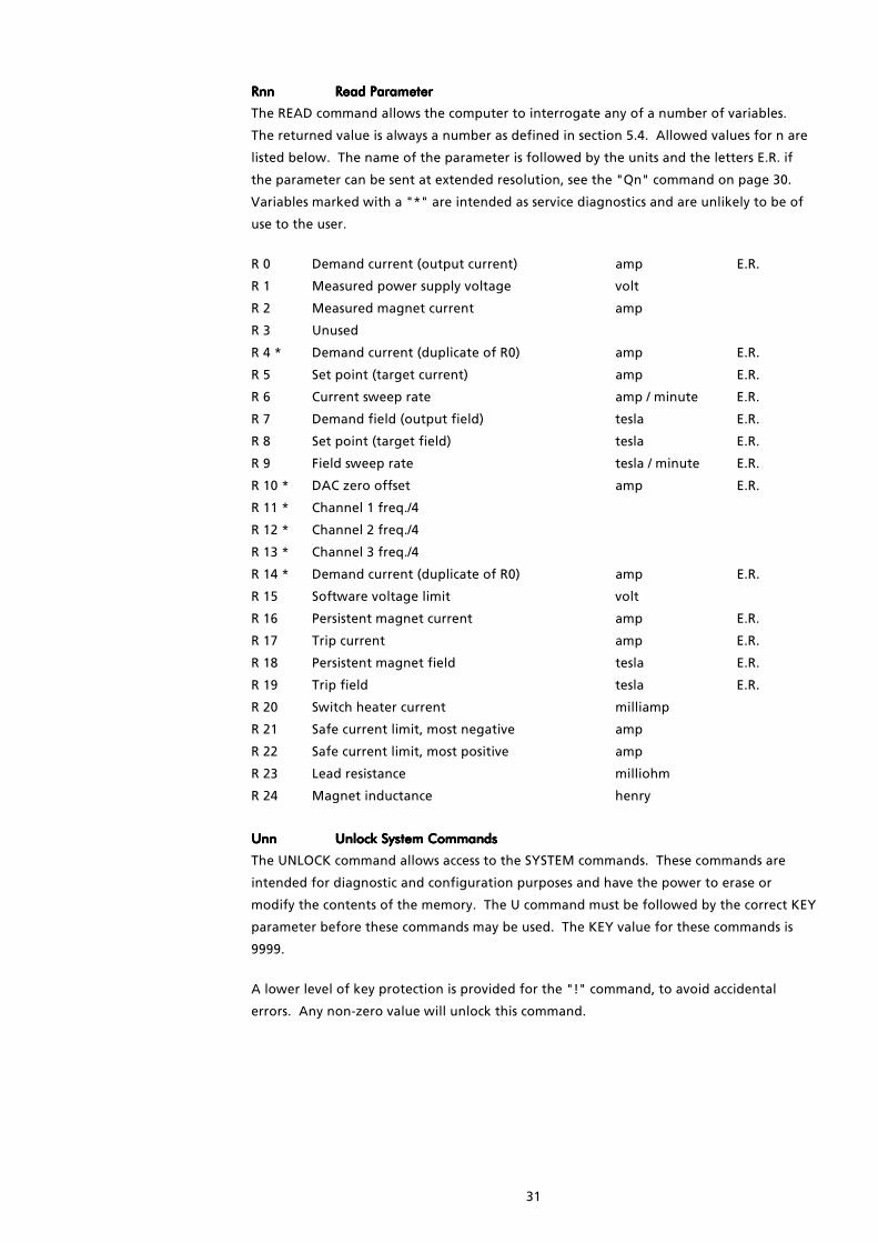
Rnn Rnn Rnn Rnn Read ParameterRead ParameterRead ParameterRead Parameter
The READ command allows the computer to interrogate any of a number of variables.
The returned value is always a number as defined in section 5.4. Allowed values for n are
listed below. The name of the parameter is followed by the units and the letters E.R. if
the parameter can be sent at extended resolution, see the "Qn" command on page 30.
Variables marked with a "*" are intended as service diagnostics and are unlikely to be of
use to the user.
R 0 Demand current (output current) amp E.R.
R 1 Measured power supply voltage volt
R 2 Measured magnet current amp
R 3 Unused
R 4 * Demand current (duplicate of R0) amp E.R.
R 5 Set point (target current) amp E.R.
R 6 Current sweep rate amp / minute E.R.
R 7 Demand field (output field) tesla E.R.
R 8 Set point (target field) tesla E.R.
R 9 Field sweep rate tesla / minute E.R.
R 10 * DAC zero offset amp E.R.
R 11 * Channel 1 freq./4
R 12 * Channel 2 freq./4
R 13 * Channel 3 freq./4
R 14 * Demand current (duplicate of R0) amp E.R.
R 15 Software voltage limit volt
R 16 Persistent magnet current amp E.R.
R 17 Trip current amp E.R.
R 18 Persistent magnet field tesla E.R.
R 19 Trip field tesla E.R.
R 20 Switch heater current milliamp
R 21 Safe current limit, most negative amp
R 22 Safe current limit, most positive amp
R 23 Lead resistance milliohm
R 24 Magnet inductance henry
Unn Unn Unn Unn Unlock System CommandsUnlock System CommandsUnlock System CommandsUnlock System Commands
The UNLOCK command allows access to the SYSTEM commands. These commands are
intended for diagnostic and configuration purposes and have the power to erase or
modify the contents of the memory. The U command must be followed by the correct KEY
parameter before these commands may be used. The KEY value for these commands is
9999.
A lower level of key protection is provided for the "!" command, to avoid accidental
errors. Any non-zero value will unlock this command.
32
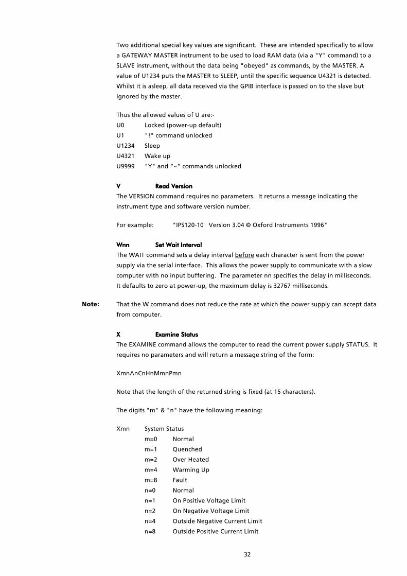
Two additional special key values are significant. These are intended specifically to allow
a GATEWAY MASTER instrument to be used to load RAM data (via a "Y" command) to a
SLAVE instrument, without the data being "obeyed" as commands, by the MASTER. A
value of U1234 puts the MASTER to SLEEP, until the specific sequence U4321 is detected.
Whilst it is asleep, all data received via the GPIB interface is passed on to the slave but
ignored by the master.
Thus the allowed values of U are:-
U0 Locked (power-up default)
U1 "!" command unlocked
U1234 Sleep
U4321 Wake up
U9999 "Y" and “~” commands unlocked
VVVV Read VersionRead VersionRead VersionRead Version
The VERSION command requires no parameters. It returns a message indicating the
instrument type and software version number.
For example: "IPS120-10 Version 3.04 © Oxford Instruments 1996"
WnnWnnWnnWnn Set Wait IntervalSet Wait IntervalSet Wait IntervalSet Wait Interval
The WAIT command sets a delay interval before each character is sent from the power
supply via the serial interface. This allows the power supply to communicate with a slow
computer with no input buffering. The parameter nn specifies the delay in milliseconds.
It defaults to zero at power-up, the maximum delay is 32767 milliseconds.
Note: That the W command does not reduce the rate at which the power supply can accept data
from computer.
XXXX Examine StatusExamine StatusExamine StatusExamine Status
The EXAMINE command allows the computer to read the current power supply STATUS. It
requires no parameters and will return a message string of the form:
XmnAnCnHnMmnPmn
Note that the length of the returned string is fixed (at 15 characters).
The digits "m" & "n" have the following meaning:
Xmn System Status
m=0 Normal
m=1 Quenched
m=2 Over Heated
m=4 Warming Up
m=8 Fault
n=0 Normal
n=1 On Positive Voltage Limit
n=2 On Negative Voltage Limit
n=4 Outside Negative Current Limit
n=8 Outside Positive Current Limit

33
An Activity (n as for A command)
n=0 Hold
n=1 To Set Point
n=2 To Zero
n=4 Clamped
Cn LOC/REM Status (n as for C command)
n=0 Local & Locked
n=1 Remote & Locked
n=2 Local & Unlocked
n=3 Remote & Unlocked
n=4 Auto-Run-Down
n=5 Auto-Run-Down
n=6 Auto-Run-Down
n=7 Auto-Run-Down
Hn Switch Heater (n as for H command)
n=0 Off Magnet at Zero (switch closed)
n=1 On (switch open)
n=2 Off Magnet at Field (switch closed)
n=5 Heater Fault (heater is on but current is low)
n=8 No Switch Fitted
Mmn Mode (m as for M command)
Display Magnet Sweep
m=0 Amps Fast
m=1 Tesla Fast
m=4 Amps Slow
m=5 Tesla Slow
n=0 At rest (output constant)
n=1 Sweeping (output changing)
n=2 Sweep Limiting (output changing)
n=3 Sweeping & Sweep Limiting (output changing)
The active states "SWEEPING" and "SWEEP LIMITING" indicate the mode in which the
output current is changing.
A changing output in IMMEDIATE mode (e.g. magnet persistent) will be flagged by SWEEP
LIMITING only. In SWEEP mode (e.g. changing the magnet current) only SWEEPING should
be flagged, but if the attempted sweep rate exceeds the sweep rate limit, SWEEP
LIMITING will also be indicated.
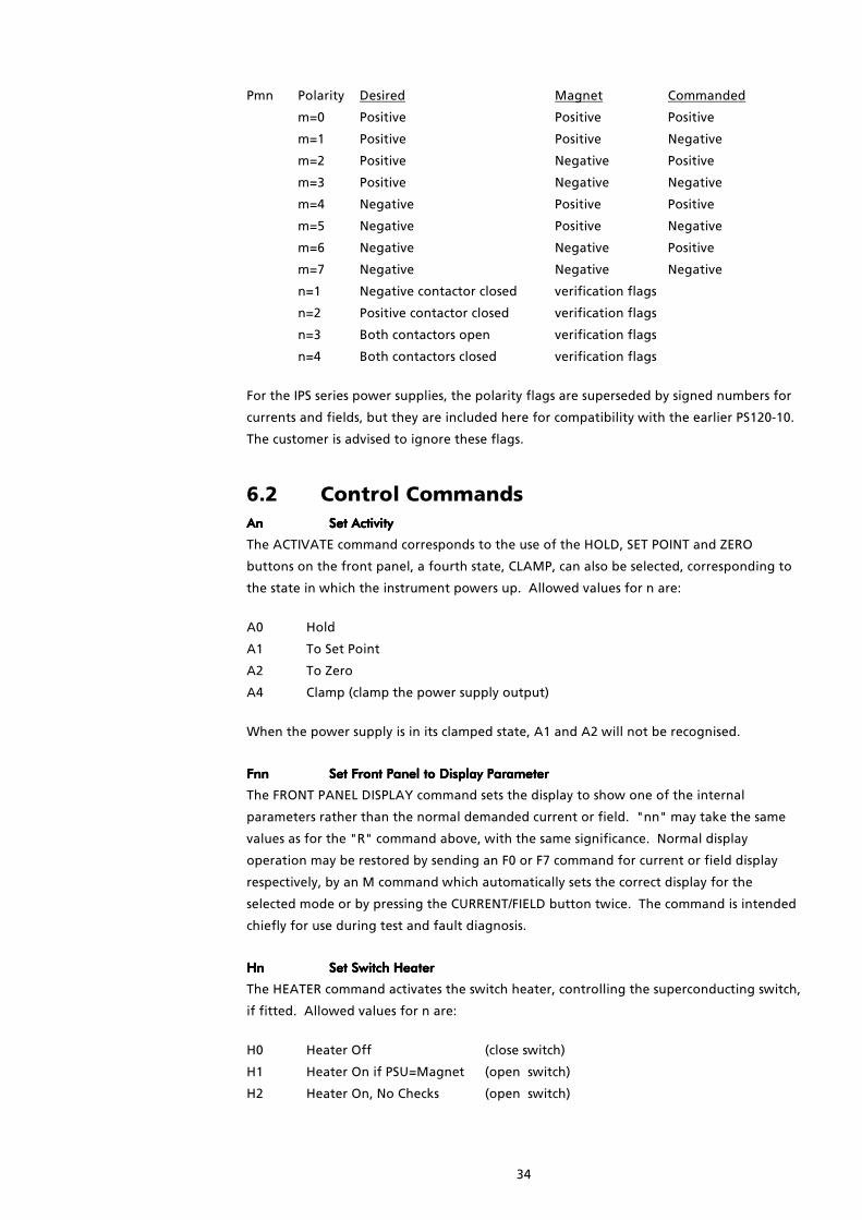
34
Pmn Polarity Desired Magnet Commanded
m=0 Positive Positive Positive
m=1 Positive Positive Negative
m=2 Positive Negative Positive
m=3 Positive Negative Negative
m=4 Negative Positive Positive
m=5 Negative Positive Negative
m=6 Negative Negative Positive
m=7 Negative Negative Negative
n=1 Negative contactor closed verification flags
n=2 Positive contactor closed verification flags
n=3 Both contactors open verification flags
n=4 Both contactors closed verification flags
For the IPS series power supplies, the polarity flags are superseded by signed numbers for
currents and fields, but they are included here for compatibility with the earlier PS120-10.
The customer is advised to ignore these flags.
6.2 Control CommandsAn An An An Set ActivitySet ActivitySet ActivitySet Activity
The ACTIVATE command corresponds to the use of the HOLD, SET POINT and ZERO
buttons on the front panel, a fourth state, CLAMP, can also be selected, corresponding to
the state in which the instrument powers up. Allowed values for n are:
A0 Hold
A1 To Set Point
A2 To Zero
A4 Clamp (clamp the power supply output)
When the power supply is in its clamped state, A1 and A2 will not be recognised.
Fnn Fnn Fnn Fnn Set Front Panel to Display ParameterSet Front Panel to Display ParameterSet Front Panel to Display ParameterSet Front Panel to Display Parameter
The FRONT PANEL DISPLAY command sets the display to show one of the internal
parameters rather than the normal demanded current or field. "nn" may take the same
values as for the "R" command above, with the same significance. Normal display
operation may be restored by sending an F0 or F7 command for current or field display
respectively, by an M command which automatically sets the correct display for the
selected mode or by pressing the CURRENT/FIELD button twice. The command is intended
chiefly for use during test and fault diagnosis.
Hn Hn Hn Hn Set Switch HeaterSet Switch HeaterSet Switch HeaterSet Switch Heater
The HEATER command activates the switch heater, controlling the superconducting switch,
if fitted. Allowed values for n are:
H0 Heater Off (close switch)
H1 Heater On if PSU=Magnet (open switch)
H2 Heater On, No Checks (open switch)

35
The H1 command will only open the switch if the recorded magnet current is equal to the
present power supply output current. Both current magnitude and polarity are considered
but +/- zero amps are considered equal.
Caution The H2 command performs no such check, and will open the switch regardless of any
apparent conflict
Please note the following points:
i) After issuing a command it is necessary to wait several seconds for the switch to
respond before assuming that it has changed state.
ii) Changing the state of the switch heater will automatically set sweep or
immediate mode. Immediate mode is selected only if a superconducting switch
is fitted and is closed. Otherwise the control of the power supply is always in
sweep mode. Note that in immediate mode, changes occur at a limiting rate, for
example 30 seconds from zero to full current, not as an instantaneous step. In
sweep mode, changes occur at a rate specified by the S or T command, unless
this would exceed the rate limit.
InnInnInnInn Set Target CurrentSet Target CurrentSet Target CurrentSet Target Current
The I command sets the SET POINT (target) current to which the power supply will sweep.
The parameter nn is the required current sent as a number in accordance with section 5.4.
The resolution of the set current is 0.001 amp, or 0.0001 amp if Extended Resolution has
been selected, see the "Qn" command on page 30.
JnnJnnJnnJnn Set Target FieldSet Target FieldSet Target FieldSet Target Field
The J command sets the SET POINT (target) field to which the power supply will sweep.
The parameter nn is the required field sent as a number in accordance with section 5.4.
The resolution of the set field is typically 0.0001 tesla, or 0.00001 tesla if Extended
Resolution has been selected, see the "Qn" command on page 30.
MnMnMnMn Set ModeSet ModeSet ModeSet Mode
The MODE command selects CURRENT or FIELD mode for the display and selects FAST or
SLOW maximum sweep rates for the magnet. Usually the user will require only to toggle
the display between 'amps' and 'tesla', for which M8 and M9 will suffice.
Mn may take the following values:
Display Magnet Sweep
M0 Amps Fast (M2 is also accepted)
M1 Tesla Fast (M3 is also accepted)
M4 Amps Slow (M6 is also accepted)
M5 Tesla Slow (M7 is also accepted)
M8 Amps Unaffected
M9 Tesla Unaffected
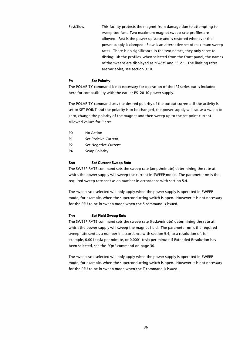
36
Fast/Slow This facility protects the magnet from damage due to attempting to
sweep too fast. Two maximum magnet sweep rate profiles are
allowed. Fast is the power up state and is restored whenever the
power supply is clamped. Slow is an alternative set of maximum sweep
rates. There is no significance in the two names, they only serve to
distinguish the profiles, when selected from the front panel, the names
of the sweeps are displayed as “FASt” and “SLo”. The limiting rates
are variables, see section 9.10.
PnPnPnPn Set PolaritySet PolaritySet PolaritySet Polarity
The POLARITY command is not necessary for operation of the IPS series but is included
here for compatibility with the earlier PS120-10 power supply.
The POLARITY command sets the desired polarity of the output current. If the activity is
set to SET POINT and the polarity is to be changed, the power supply will cause a sweep to
zero, change the polarity of the magnet and then sweep up to the set point current.
Allowed values for P are:
P0 No Action
P1 Set Positive Current
P2 Set Negative Current
P4 Swap Polarity
SnnSnnSnnSnn Set Current Sweep RateSet Current Sweep RateSet Current Sweep RateSet Current Sweep Rate
The SWEEP RATE command sets the sweep rate (amps/minute) determining the rate at
which the power supply will sweep the current in SWEEP mode. The parameter nn is the
required sweep rate sent as an number in accordance with section 5.4.
The sweep rate selected will only apply when the power supply is operated in SWEEP
mode, for example, when the superconducting switch is open. However it is not necessary
for the PSU to be in sweep mode when the S command is issued.
TnnTnnTnnTnn Set Field Sweep RateSet Field Sweep RateSet Field Sweep RateSet Field Sweep Rate
The SWEEP RATE command sets the sweep rate (tesla/minute) determining the rate at
which the power supply will sweep the magnet field. The parameter nn is the required
sweep rate sent as a number in accordance with section 5.4; to a resolution of, for
example, 0.001 tesla per minute, or 0.0001 tesla per minute if Extended Resolution has
been selected, see the "Qn" command on page 30.
The sweep rate selected will only apply when the power supply is operated in SWEEP
mode, for example, when the superconducting switch is open. However it is not necessary
for the PSU to be in sweep mode when the T command is issued.

37
6.3 System CommandsYnYnYnYn Load RAM ContentsLoad RAM ContentsLoad RAM ContentsLoad RAM Contents
The Y command allows the entire contents of the RAM memory to be loaded in binary, via
the serial or GPIB interface. It is not intended as a user command and will only be obeyed
after a correct "U" password. If n is omitted or has the value 2, only the first 2 kilobytes of
the memory will be loaded. If n has the value 8, the entire 8 kilobytes are loaded. Note
that after loading the memory in this way, the new content will be lost at power-down,
unless it has been saved by the “~” command or by a STORE sequence as described in
section 9.3.
ZnZnZnZn Dump RAM ContentsDump RAM ContentsDump RAM ContentsDump RAM Contents
The Z command allows the entire contents of the RAM memory to be dumped in binary,
via the serial or GPIB interface. It is not intended as a user command. Like the Y
command, omitting n or setting it to 2 results in a 2 kilobyte dump. Setting n to 8 gives a
full 8 kilobyte dump.
!!!! Set ISOBUS AddressSet ISOBUS AddressSet ISOBUS AddressSet ISOBUS Address
See section 5.5
~~~~ Store DataStore DataStore DataStore Data
The ~ (tilde) command stores any changes made to the calibration data in the power
supply, otherwise the changes will be lost after power down. It will only be obeyed after
the correct “U” password.
The front panel display of the instrument will show the message “Stor” if the store
command is successful, if a “Prot” message is displayed, then the hardware write-enable
switch is in the OFF position, see section 9.3
In general the commands in this section are not intended for customer use. They have
been provided for engineering use during algorithm development and to interface with
certain Oxford Instruments application software. The details which follow are provided
for interest only. They are correct for this version of firmware but future versions will not
necessarily retain the commands in the same form. A command letter followed by “..”
indicates that a numeric value should be appended to the command.
aaaa Read Auto-Run-Down StatusRead Auto-Run-Down StatusRead Auto-Run-Down StatusRead Auto-Run-Down Status
No further description here.
cccc Read Damping ParameterRead Damping ParameterRead Damping ParameterRead Damping Parameter
No further description here.
dddd Read Damping CoefficientRead Damping CoefficientRead Damping CoefficientRead Damping Coefficient
No further description here.
e..e..e..e.. Set Damping CoefficientSet Damping CoefficientSet Damping CoefficientSet Damping Coefficient
No further description here.
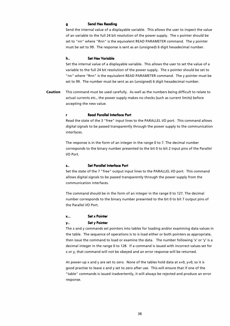
38
gggg Send Hex ReadingSend Hex ReadingSend Hex ReadingSend Hex Reading
Send the internal value of a displayable variable. This allows the user to inspect the value
of an variable to the full 24 bit resolution of the power supply. The x pointer should be
set to "nn" where "Rnn" is the equivalent READ PARAMETER command. The y pointer
must be set to 99. The response is sent as an (unsigned) 6 digit hexadecimal number.
h..h..h..h.. Set Hex VariableSet Hex VariableSet Hex VariableSet Hex Variable
Set the internal value of a displayable variable. This allows the user to set the value of a
variable to the full 24 bit resolution of the power supply. The x pointer should be set to
"nn" where "Rnn" is the equivalent READ PARAMETER command. The y pointer must be
set to 99. The number must be sent as an (unsigned) 6 digit hexadecimal number.
Caution This command must be used carefully. As well as the numbers being difficult to relate to
actual currents etc., the power supply makes no checks (such as current limits) before
accepting the new value.
rrrr Read ParallelRead ParallelRead ParallelRead Parallel Interface Port Interface Port Interface Port Interface Port
Read the state of the 3 "free" input lines to the PARALLEL I/O port. This command allows
digital signals to be passed transparently through the power supply to the communication
interfaces.
The response is in the form of an integer in the range 0 to 7. The decimal number
corresponds to the binary number presented to the bit 0 to bit 2 input pins of the Parallel
I/O Port.
s..s..s..s.. Set Parallel Interface PortSet Parallel Interface PortSet Parallel Interface PortSet Parallel Interface Port
Set the state of the 7 "free" output input lines to the PARALLEL I/O port. This command
allows digital signals to be passed transparently through the power supply from the
communication interfaces.
The command should be in the form of an integer in the range 0 to 127. The decimal
number corresponds to the binary number presented to the bit 0 to bit 7 output pins of
the Parallel I/O Port.
x...x...x...x... Set x PointerSet x PointerSet x PointerSet x Pointer
y..y..y..y.. Set y PointerSet y PointerSet y PointerSet y Pointer
The x and y commands set pointers into tables for loading and/or examining data values in
the table. The sequence of operations is to is load either or both pointers as appropriate,
then issue the command to load or examine the data. The number following ‘x’ or ‘y’ is a
decimal integer in the range 0 to 128. If a command is issued with incorrect values set for
x or y, that command will not be obeyed and an error response will be returned.
At power-up x and y are set to zero. None of the tables hold data at x=0, y=0; so it is
good practise to leave x and y set to zero after use. This will ensure that if one of the
"table" commands is issued inadvertently, it will always be rejected and produce an error
response.

39
7 Auto-Run-DownAuto-run-down will automatically de-energise a magnet system in response to an external
signal. It does not provide a particularly fast means of doing so. It is primarily intended
for use with a helium level meter, as a means of protecting a magnet or magnet switch
from damage should the helium level in the magnet cryostat drop too far.
Caution This function can only operate if the power supply is left switched on
The auto-run-down function is invoked via the rear panel marked "PARALLEL I/O", see
section 3.7.
While auto-run-down is active, local and remote control are locked out and the lights in
the front panel section marked "CONTROL" will flash.
The power supply performs the following sequence of actions fully automatically during
auto-run-down:-
i) If the power supply is clamped, then unclamp the magnet.
ii) If the switch heater is off, then quickly sweep the leads to where the magnet was last
put persistent.
iii) If the switch heater is off, then wait 20 seconds and turn the switch heater on.
iv) De-energise the magnet in a low-voltage mode (+/- 1).
v) When the magnet is de-energised, wait 20 seconds to ensure no further activity, then
clamp the output and turn off the switch heater (if fitted).
The operator cannot regain control of the power supply until the external signal is cleared
(or disconnected).

40
8 Fault ConditionsThis section includes only those faults which are indicated by the power supply being in an
unusual state. Faults concerning the magnet system as a whole are not described here,
the user should refer to the magnet system handbooks or manuals.
8.1 Fault IndexFaults may be caused by internal or external conditions. The power supply overheating is
an example of an internal fault and mains failure is an example of an external fault.
There are some other conditions that are not strictly faults but are mentioned here for
completeness.
Most of the faults are not fully described in this section but the following table indexes
them all.
8.2 Mains FailureIf the mains supply fails, or if the power supply is suddenly switched off, the magnet
terminals are immediately clamped by mechanical contacts. The analogue meter
continues to show the output current.
A magnet with the switch heater on (or without a persistent switch), will slowly run down.
A persistent magnet (zero lead current) with the switch heater off will remain persistent.
When the mains is reconnected the power supply will remain in the clamped state with
the switch heater off. The operator can resume control by pressing HOLD to unclamp the
output.
If the magnet was persistent then the power supply will remember the magnet current at
the time when the power failure occurred. Operation can resume as though no
interruption had occurred.
If the magnet was not persistent at the time of the power failure, then the output will
typically go to the voltage limits and be caught as described in section 4.2. Turn on the
switch heater and wait long enough for the switch to open before continuing with
interrupted operations.
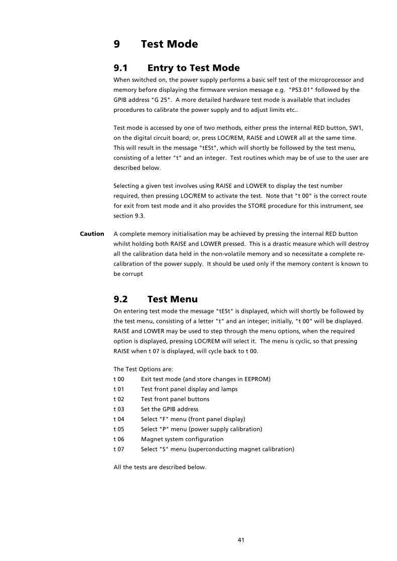
41
9 Test Mode
9.1 Entry to Test ModeWhen switched on, the power supply performs a basic self test of the microprocessor and
memory before displaying the firmware version message e.g. "PS3.01" followed by the
GPIB address "G 25". A more detailed hardware test mode is available that includes
procedures to calibrate the power supply and to adjust limits etc..
Test mode is accessed by one of two methods, either press the internal RED button, SW1,
on the digital circuit board; or, press LOC/REM, RAISE and LOWER all at the same time.
This will result in the message "tESt", which will shortly be followed by the test menu,
consisting of a letter "t" and an integer. Test routines which may be of use to the user are
described below.
Selecting a given test involves using RAISE and LOWER to display the test number
required, then pressing LOC/REM to activate the test. Note that "t 00" is the correct route
for exit from test mode and it also provides the STORE procedure for this instrument, see
section 9.3.
Caution A complete memory initialisation may be achieved by pressing the internal RED button
whilst holding both RAISE and LOWER pressed. This is a drastic measure which will destroy
all the calibration data held in the non-volatile memory and so necessitate a complete re-
calibration of the power supply. It should be used only if the memory content is known to
be corrupt
9.2 Test MenuOn entering test mode the message "tESt" is displayed, which will shortly be followed by
the test menu, consisting of a letter "t" and an integer; initially, "t 00" will be displayed.
RAISE and LOWER may be used to step through the menu options, when the required
option is displayed, pressing LOC/REM will select it. The menu is cyclic, so that pressing
RAISE when t 07 is displayed, will cycle back to t 00.
The Test Options are:
t 00 Exit test mode (and store changes in EEPROM)
t 01 Test front panel display and lamps
t 02 Test front panel buttons
t 03 Set the GPIB address
t 04 Select "F" menu (front panel display)
t 05 Select "P" menu (power supply calibration)
t 06 Magnet system configuration
t 07 Select "S" menu (superconducting magnet calibration)
All the tests are described below.

42
9.3 Test 00 Exit (and Storing Calibration Data)This option should be used for exit from test mode. On exit the user is prompted to
STORE any data that has been changed in test mode.
The power supply contains several types of memory circuits. Changes to any of the
parameters in test mode will be retained while the power supply is switched on. If the
changes are not stored then when the unit is switched on again, the original calibration
parameters will be restored.
On entry to test 0, the display reads "Stor.y" press RAISE or LOWER and the display toggles
to "Stor.n". Press LOC/REM to exit test 0 and return to the normal mode. If on exit, the
display reads "Stor.y", then the calibration data will be stored. If the display reads
"Stor.n", then the new data will not be stored. It is unlikely that a user will require the
"Stor.n" option.
If "Stor.y" has been selected, The display will briefly show "Stor" indicating that the data
has been correctly stored. If instead of showing "Stor", the display shows "Prot", this
indicates that the memory is protected by the hardware WRITE-ENABLE switch being in
the OFF position. This is Switch 1 of a small 2 way Dual-in-Line switch SW2 on the digital
circuit board (CBL1200). Set it to the "ON" position and try again. The switch need only
be returned to the OFF position if it is desired to prevent any possibility of the data being
changed by someone tampering with the front panel. When the power supply leaves the
factory, this switch is normally ON, allowing changes to be stored.
9.4 Test 01 Test Front Panel LampsLights each LED or display segment in turn, then pulls each of the auxiliary (parallel
interface) output lines low in turn. When the test is complete, the unit returns to the test
menu.
9.5 Test 02 Test Front Panel ButtonsTests the control buttons. When the test is entered, the display will be blank. If the
buttons are pressed, one at a time, each should light a single segment in the upper half of
the display. Stuck buttons will give a permanently lit segment. If more than one segment
lights for a single button, track shorts are indicated. To leave test 2, POWER must be
switched off.
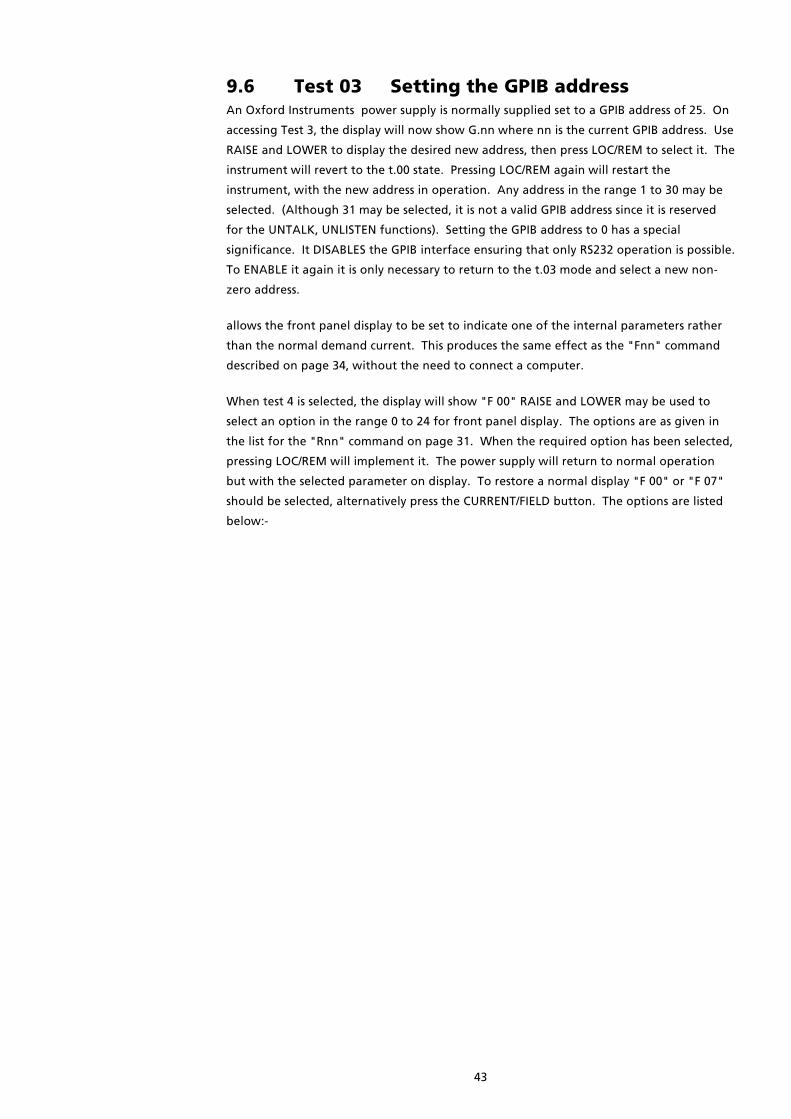
43
9.6 Test 03 Setting the GPIB addressAn Oxford Instruments power supply is normally supplied set to a GPIB address of 25. On
accessing Test 3, the display will now show G.nn where nn is the current GPIB address. Use
RAISE and LOWER to display the desired new address, then press LOC/REM to select it. The
instrument will revert to the t.00 state. Pressing LOC/REM again will restart the
instrument, with the new address in operation. Any address in the range 1 to 30 may be
selected. (Although 31 may be selected, it is not a valid GPIB address since it is reserved
for the UNTALK, UNLISTEN functions). Setting the GPIB address to 0 has a special
significance. It DISABLES the GPIB interface ensuring that only RS232 operation is possible.
To ENABLE it again it is only necessary to return to the t.03 mode and select a new non-
zero address.
allows the front panel display to be set to indicate one of the internal parameters rather
than the normal demand current. This produces the same effect as the "Fnn" command
described on page 34, without the need to connect a computer.
When test 4 is selected, the display will show "F 00" RAISE and LOWER may be used to
select an option in the range 0 to 24 for front panel display. The options are as given in
the list for the "Rnn" command on page 31. When the required option has been selected,
pressing LOC/REM will implement it. The power supply will return to normal operation
but with the selected parameter on display. To restore a normal display "F 00" or "F 07"
should be selected, alternatively press the CURRENT/FIELD button. The options are listed
below:-

44
9.7 Test 04 F (Front Panel Display) Menu
F 1 Measured power supply voltage volt
F 2 Measured magnet current amp
F 3 Unused
F 4 * Demand current (duplicate of R0) amp
F 5 Set point (target current) amp
F 6 Current sweep rate amp / minute
F 7 Demand field (output field) tesla
F 8 Set point (target field) tesla
F 9 Field sweep rate tesla / minute
F 10 * DAC zero offset amp
F 11 * Channel 1 freq./4
F 12 * Channel 2 freq./4
F 13 * Channel 3 freq./4
F 14 * Demand current (duplicate of R0) amp
F 15 Software voltage limit volt
F 16 Persistent magnet current amp
F 17 Trip current amp
F 18 Persistent magnet field tesla
F 19 Trip field tesla
F 20 Switch heater current milliamp
F 21 Safe current limit, most negative amp
F 22 Safe current limit, most positive amp
F 23 Lead resistance milliohm
F 24 Magnet inductance henry
Variables marked with a "*" are intended as service diagnostics and are unlikely to be of
use to the user.
9.8 Test 05 PSU (Power Supply) MenuThis menu provides access to a set of operations designed to be carried out when initially
setting up a power supply. The majority will not be needed thereafter unless hardware
changes are made.
Caution The "Psu" menu changes the calibration of the power supply and magnet.
"Psu" is entered from test 5 in the Test Menu, resulting in "PSU" being briefly displayed
followed by "P" and an integer. RAISE and LOWER may be used to step through the
menu and LOC/REM used to choose an option.
Note that the power supply may prevent casual entry to the Psu menu. If the user tries to
enter this mode and the power supply current is not zero, a "not 0 Error" message will be
displayed and the display returns to "t 00". This check is to protect the magnet system
from damage as the output will be clamped on entry to the PSU menu and this may cause
problems! The safety feature may be overridden by pressing and holding LOC/REM whilst
the error message is displayed.

45
These are the available options.
P 00 Return to test menu
P 01 Not used
P 02 Define power supply current range
P 03 Adjust power supply zero correction
P 04 Step through DAC outputs
P 05 Test output damping
P 06 Not used
P 07 Not used
P 08 Not used
P 09 Not used
P 10 Calibrate voltage monitor at negative voltage limit
P 11 Calibrate voltage monitor at positive voltage limit
P 12 Auto-calibration of current monitor
P 13 Not used
P 14 Auto-zero power supply
P 15 Not used
Psu 02 Psu 02 Psu 02 Psu 02 Define Power Supply Current Range.Define Power Supply Current Range.Define Power Supply Current Range.Define Power Supply Current Range.
Caution Oxford Instruments advises the user not to change the current range unless a precision
high current shunt is available for re-calibration. Note that changing this parameter will
also affect all other "Psu" and "Sup" calibrations. Perhaps what is required is test 7, Sup
2, define power supply current limit?
On entry, the display shows "I CAL" (current calibrate), press LOC/REM again and the
power supply returns to the menu. To display or adjust the current range, display I CAL
then press RAISE, LOWER and LOC/REM.
The number is set to the rated output current of the power supply, for example, 120.000
for a normal IPS120-10. Initially, RAISE and LOWER may be used to shift the decimal point
to the required position. Depress LOC/REM and use RAISE and LOWER to set the number
required.
Psu 03 Psu 03 Psu 03 Psu 03 Adjust Power Supply Zero CorrectionAdjust Power Supply Zero CorrectionAdjust Power Supply Zero CorrectionAdjust Power Supply Zero Correction
This is a software trim for the zero current of the power supply. On entry, the present
value is displayed as a number of amps, depressing LOC/REM allows this value to be
adjusted over a small range. The default setting is 00.000
For the duration of this test, the output of the power supply is unclamped, thus the offset
current can be measured between the power supply's magnet terminals. An easy way of
doing this is to place a 1 kohm resistor across the output, the "OUTPUT VOLTAGE" meter
will now display the offset current to the scale of 1 volt/mA.
Psu 04 Psu 04 Psu 04 Psu 04 Step Through DAC OutputsStep Through DAC OutputsStep Through DAC OutputsStep Through DAC Outputs
This test is intended for checking the output of the power supply's DAC. For the duration
of this test, the output of the power supply is clamped. Therefore no current will flow
between the magnet terminals and the output of the DAC can be safely measured at test
point TP303 on the analogue pcb (mounted upside down in the top of the power supply).

46
On entering Psu 04, the display will briefly read "d 00" followed by -10.0000 volts. This
display indicates approximately what voltage the DAC should output. Pressing RAISE or
LOWER will cycle the DAC from "d 01" to "d 16", while the button is depressed the display
will read "d nn", indicating which data line to the DAC is made active. When the button
is released, the calculated DAC output voltage will be displayed. To exit Psu 04, press
LOC/REM.
Psu 05 Psu 05 Psu 05 Psu 05 Test Output DampingTest Output DampingTest Output DampingTest Output Damping
This test is intended for checking the components which provide filtering and damping of
the output. For this test, connections to the "magnet" terminals must be removed. The
output is made to oscillate between the hardware voltage limits, and the display shows
the average period of the oscillation (the units are seconds). Press LOC/REM repeatedly
and the output will oscillate at two different rates, then exit.
Psu 10 Psu 10 Psu 10 Psu 10 Calibrate Voltage Monitor at the Negative LimitCalibrate Voltage Monitor at the Negative LimitCalibrate Voltage Monitor at the Negative LimitCalibrate Voltage Monitor at the Negative Limit
Psu 11 Psu 11 Psu 11 Psu 11 Calibrate Voltage Monitor at the Positive LimitCalibrate Voltage Monitor at the Positive LimitCalibrate Voltage Monitor at the Positive LimitCalibrate Voltage Monitor at the Positive Limit
These tests calibrate the power supply voltage monitor. Psu 10 calibrates the measured
voltage at the negative (hardware) voltage limit, normally -10 or -20 volts. Psu 11
calibrates the measured voltage at the positive (hardware) voltage limit, normally +10 or
+20 volts.
These tests require existing connections to the "magnet" and "switch heater" terminals to
be removed. A voltage meter set to read at least +/-10 or +/-20 volts should be connected
from the negative to the positive magnet terminals.
On entry to Psu 10 or Psu 11, the power supply will display "PAUSE" as the output voltage
sweeps to the (hardware) voltage limit. The display will then change to show the
measured output voltage. To alter the calibration, depress LOC/REM and use RAISE and
LOWER to set the display to the voltage measured on the external voltage meter.
Releasing LOC/REM causes the output voltage to clamp and drop to about 1/10th of its
normal value. Pressing the LOC/REM button once more to return to the "Psu" menu.
Exit from Psu 10 and Psu 11 must be via the correct route else corruption of the zero
setting of the power supply will result. Pressing LOC/REM at any time will abort the test
and return to the Psu menu.
If large adjustments are needed, it will may be necessary to repeat Psu 10 and Psu 11 until
both points are calibrated.
To change the hardware voltage limits, the power supply must be opened up and access
obtained to the analogue pcb (mounted upside down in the top of the power supply). To
adjust the negative limit, enter Psu 10 as described above and adjust RV301 to set the
required limit. To adjust the positive limit, enter Psu 11 as described above and adjust
RV302 to set the required limit.
Psu 12 Psu 12 Psu 12 Psu 12 Auto-Calibration of Current MonitorAuto-Calibration of Current MonitorAuto-Calibration of Current MonitorAuto-Calibration of Current Monitor
This test automatically calibrates the measured lead current of the power supply. All
existing connections to the "magnet" and "switch heater" terminals must be removed. A
busbar should then be connected between the two magnet terminals.
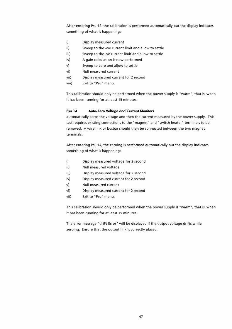
47
After entering Psu 12, the calibration is performed automatically but the display indicates
something of what is happening:-
i) Display measured current
ii) Sweep to the +ve current limit and allow to settle
iii) Sweep to the -ve current limit and allow to settle
iv) A gain calculation is now performed
v) Sweep to zero and allow to settle
vi) Null measured current
vii) Display measured current for 2 second
viii) Exit to "Psu" menu.
This calibration should only be performed when the power supply is "warm", that is, when
it has been running for at least 15 minutes.
Psu 14 Psu 14 Psu 14 Psu 14 Auto-Zero Voltage and Current MonitorsAuto-Zero Voltage and Current MonitorsAuto-Zero Voltage and Current MonitorsAuto-Zero Voltage and Current Monitors
automatically zeros the voltage and then the current measured by the power supply. This
test requires existing connections to the "magnet" and "switch heater" terminals to be
removed. A wire link or busbar should then be connected between the two magnet
terminals.
After entering Psu 14, the zeroing is performed automatically but the display indicates
something of what is happening:-
i) Display measured voltage for 2 second
ii) Null measured voltage
iii) Display measured voltage for 2 second
iv) Display measured current for 2 second
v) Null measured current
vi) Display measured current for 2 second
vii) Exit to "Psu" menu.
This calibration should only be performed when the power supply is "warm", that is, when
it has been running for at least 15 minutes.
The error message "driFt Error" will be displayed if the output voltage drifts while
zeroing. Ensure that the output link is correctly placed.

48
9.9 Test 06 Magnet System ConfigurationThe “configuration” defines what type of magnet system will be used with the power
supply.
On entry to test 6, a number in the range 0 to 255 is displayed, this represents the
"configuration" and may be adjusted by pressing LOC/REM and using RAISE and LOWER,
releasing LOC/REM returns to the test menu. Certain "configurations" are not allowed,
the power supply will reject these, display "ConF Error", then display the previous
configuration.
The displayed, decimal, number represents an 8-bit binary number, where the bits have
the following significance (Bit 0 is LSB):
Bit 0 Superconducting switch fitted.
Should be set if a superconducting switch is fitted to the magnet. If this bit is set
then the switch heater button is enabled.
Bit 1 Add output filter current compensation.
Adds a correction term to the output current to compensate for the effect of the
power supply's output filter. This function may not be selected if the magnet is
fitted with a superconducting switch.
The output of the magnet power supply is fitted with a network of large
capacitors, these are needed to reduce the voltage noise generated by the
combination of a current source (the power supply) and a very large inductance
(the magnet). If the output current is constant or the output is changing at a
constant rate, then there is no current into the capacitors. However at the
beginning and end of a sweep, the capacitors must be charged to the voltage on
the magnet. If this function is selected, then the power supply calculates this
charge current and adds it to the normal output current.
The accuracy of this function relies on the magnet inductance being set correctly,
see Sup 11 on page 52.
Bit 2 Ignore voltage transients.
Set this bit to avoid the magnet “catching” routine being triggered by voltage
transients caused by the beginning or end of a sweep. The catch mechanism will
then ignore the first 2 seconds of voltage limiting, it will only trigger if voltage
limiting persists for longer than this time.
The transient is due to a low frequency resonance between the magnet and the
output capacitors of the power supply. For unswitched magnets, setting Bit 1
may help reduce the transient.

49
Bit 3 Unipolar version of the power supply.
If an IPS power supply is configured as unipolar at the factory, a plug is
disconnected from pins 11 & 12 of PL501 on the analogue pcb (mounted upside
down in the top of the power supply). This ensures that the positive current
contactor remains closed and negative currents are impossible. The user may
reconfigure the unit as bipolar by reconnecting this plug and changing bit 3 to
zero as described above.
The following are the most commonly required configurations:
0 No persistent switch fitted to magnet
1 Persistent switch fitted to magnet
2 No persistent switch, add correction current.
4 No persistent switch, ignore voltage transients.
6 No persistent switch, add correction current, ignore voltage transients.
8 Unipolar power supply, no switch fitted.
9 Unipolar power supply, switch fitted.

50
9.10 Test 07 SUP(superconducting magnet)Menu
The "Sup" menu provides access to a set of operations designed to be carried out when
initially setting up a magnet system. The majority will not be needed thereafter unless
hardware changes are made.
"Sup" is entered from test 7 in the Test Menu, resulting in "Sup" being briefly displayed
followed by "S" and an integer. RAISE and LOWER may be used to step through the
menu and LOC/REM used to choose an option.
The table which follows lists the available options.
S 00 Return to test menu
S 01 Define amps/tesla
S 02 * Define power supply current limit
S 03 Define lower (most negative) safe current
S 04 Define upper (most positive) safe current
S 05 * Define current breakpoints for rate limiting
S 06 * Define limiting rate for leads, magnet at zero
S 07 * Define limiting rate for leads, magnet at field
S 08 * Define limiting rate for magnet, "FASt" run
S 09 * Define limiting rate for magnet, "SLO" (slow) run
S 10 Define software voltage limit
S 11 Define magnet inductance
S 12 Not used
S 13 Not used
S 14 Not used
S 15 Define switch heater current
* Menu options that are marked with a “*” allow fast setting to their maximum or
minimum values. Press LOC/REM to display the current value then press LOWER
to display the minimum value and while pressing LOWER, press LOC/REM again
to latch and adjust it. Pressing RAISE displays (and adjusts) the maximum value
for the variable.
Sup 01 Sup 01 Sup 01 Sup 01 Define Amps/TeslaDefine Amps/TeslaDefine Amps/TeslaDefine Amps/Tesla
Defines a linear constant relating current and field. On entry, the maximum available
current is displayed and may be adjusted by depressing LOC/REM and using RAISE and
LOWER. Releasing LOC/REM causes an equivalent field to be displayed, which again can
be adjusted. Initially, RAISE and LOWER may be used to shift the decimal point to the
required position, then press LOC/REM and use RAISE and LOWER to set the number
required. For accuracy, the 'amps' and 'tesla' entered should be large, convenient
numbers.
Sup 02 Sup 02 Sup 02 Sup 02 Define Power Supply Current LimitDefine Power Supply Current LimitDefine Power Supply Current LimitDefine Power Supply Current Limit
defines the power supply current limit. On entry the present limit is displayed and may be
adjusted by depressing LOC/REM and using RAISE and LOWER. It will not be possible to
set a SET POINT current greater than this limit.
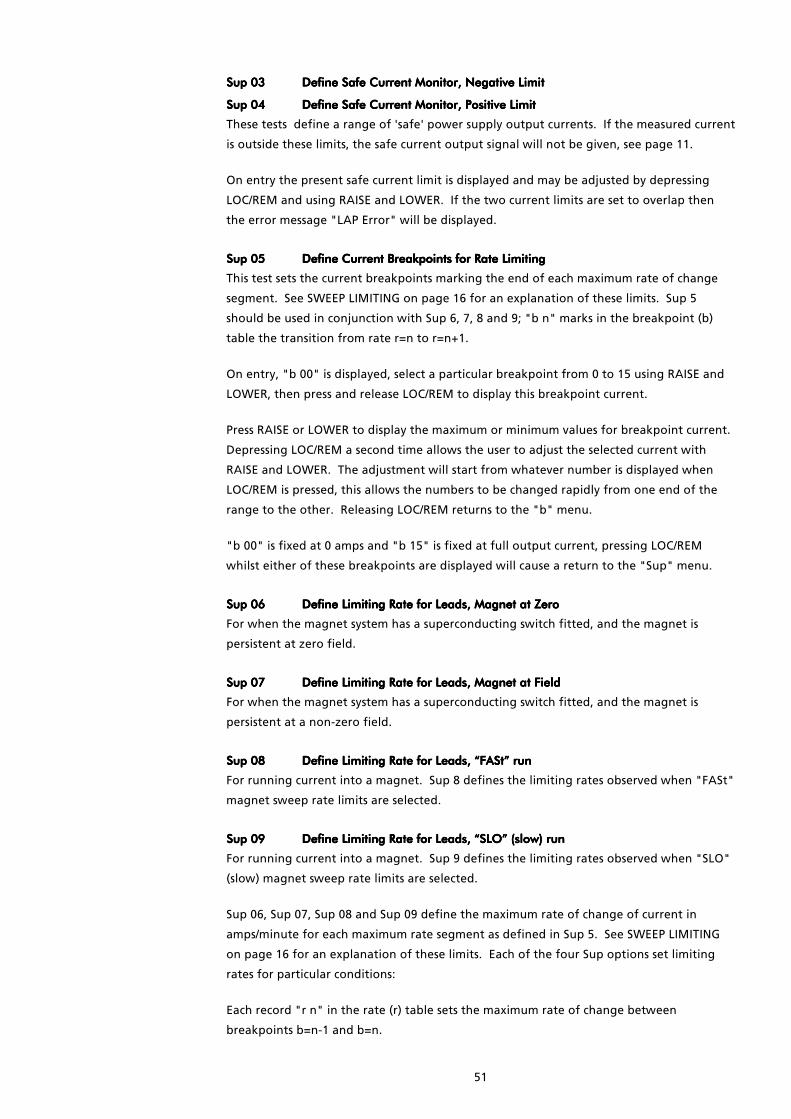
51
Sup 03 Sup 03 Sup 03 Sup 03 Define Safe Current Monitor, Negative LimitDefine Safe Current Monitor, Negative LimitDefine Safe Current Monitor, Negative LimitDefine Safe Current Monitor, Negative Limit
Sup 04 Sup 04 Sup 04 Sup 04 Define Safe Current Monitor, Positive LimitDefine Safe Current Monitor, Positive LimitDefine Safe Current Monitor, Positive LimitDefine Safe Current Monitor, Positive Limit
These tests define a range of 'safe' power supply output currents. If the measured current
is outside these limits, the safe current output signal will not be given, see page 11.
On entry the present safe current limit is displayed and may be adjusted by depressing
LOC/REM and using RAISE and LOWER. If the two current limits are set to overlap then
the error message "LAP Error" will be displayed.
Sup 05 Sup 05 Sup 05 Sup 05 Define Current Breakpoints for Rate LimitingDefine Current Breakpoints for Rate LimitingDefine Current Breakpoints for Rate LimitingDefine Current Breakpoints for Rate Limiting
This test sets the current breakpoints marking the end of each maximum rate of change
segment. See SWEEP LIMITING on page 16 for an explanation of these limits. Sup 5
should be used in conjunction with Sup 6, 7, 8 and 9; "b n" marks in the breakpoint (b)
table the transition from rate r=n to r=n+1.
On entry, "b 00" is displayed, select a particular breakpoint from 0 to 15 using RAISE and
LOWER, then press and release LOC/REM to display this breakpoint current.
Press RAISE or LOWER to display the maximum or minimum values for breakpoint current.
Depressing LOC/REM a second time allows the user to adjust the selected current with
RAISE and LOWER. The adjustment will start from whatever number is displayed when
LOC/REM is pressed, this allows the numbers to be changed rapidly from one end of the
range to the other. Releasing LOC/REM returns to the "b" menu.
"b 00" is fixed at 0 amps and "b 15" is fixed at full output current, pressing LOC/REM
whilst either of these breakpoints are displayed will cause a return to the "Sup" menu.
Sup 06 Sup 06 Sup 06 Sup 06 Define Limiting Rate for LeadDefine Limiting Rate for LeadDefine Limiting Rate for LeadDefine Limiting Rate for Leads, Magnet at Zeros, Magnet at Zeros, Magnet at Zeros, Magnet at Zero
For when the magnet system has a superconducting switch fitted, and the magnet is
persistent at zero field.
Sup 07 Sup 07 Sup 07 Sup 07 Define Limiting Rate for Leads, Magnet at FieldDefine Limiting Rate for Leads, Magnet at FieldDefine Limiting Rate for Leads, Magnet at FieldDefine Limiting Rate for Leads, Magnet at Field
For when the magnet system has a superconducting switch fitted, and the magnet is
persistent at a non-zero field.
Sup 08 Sup 08 Sup 08 Sup 08 Define Limiting Rate for Leads, “FASt” runDefine Limiting Rate for Leads, “FASt” runDefine Limiting Rate for Leads, “FASt” runDefine Limiting Rate for Leads, “FASt” run
For running current into a magnet. Sup 8 defines the limiting rates observed when "FASt"
magnet sweep rate limits are selected.
Sup 09 Sup 09 Sup 09 Sup 09 Define Limiting Rate for Define Limiting Rate for Define Limiting Rate for Define Limiting Rate for Leads, “SLO” (slow) runLeads, “SLO” (slow) runLeads, “SLO” (slow) runLeads, “SLO” (slow) run
For running current into a magnet. Sup 9 defines the limiting rates observed when "SLO"
(slow) magnet sweep rate limits are selected.
Sup 06, Sup 07, Sup 08 and Sup 09 define the maximum rate of change of current in
amps/minute for each maximum rate segment as defined in Sup 5. See SWEEP LIMITING
on page 16 for an explanation of these limits. Each of the four Sup options set limiting
rates for particular conditions:
Each record "r n" in the rate (r) table sets the maximum rate of change between
breakpoints b=n-1 and b=n.

52
On entry, "r 00" is displayed, RAISE and LOWER may be used to step to a particular
segment from 0 to 15, press and release LOC/REM to display this maximum sweep rate in
amps/minute.
Press RAISE or LOWER to display the maximum or minimum values for rate of change of
current. Depressing LOC/REM a second time allows the user to adjust the selected sweep
rate with RAISE and LOWER. The adjustment will start from whatever number is displayed
when LOC/REM is pressed, this allows the numbers to be changed rapidly from one end of
the range to the other. Releasing LOC/REM returns to the "r" menu.
Pressing LOC/REM whilst "r 00" is displayed will cause a return to the "Sup" menu.
Sup 10 Sup 10 Sup 10 Sup 10 Define SoftDefine SoftDefine SoftDefine Software Voltage Limitware Voltage Limitware Voltage Limitware Voltage Limit
defines the characteristics of the software voltage limits. These limits are usually inhibited
and are primarily intended to be used to protect magnets at the end of long or very
resistive leads. Two parameters can be set, the voltage at which limiting should occur and
the period for which the limit must be exceeded before any limiting action is taken.
On entry, the software voltage limit is displayed and may be adjusted by depressing
LOC/REM and using RAISE and LOWER. Positive and negative voltage limits are set to the
same value. By continuously monitoring the resistivity of the magnet system, the power
supply is able to take into account the voltage drop along the current leads. Thus the
software voltage limit should be set to just less than the voltage at which the magnet
protection circuit would start to conduct.
When LOC/REM is released the display will read "SPELL" for a second then a time period,
the 'spell', will be displayed. If the output voltage should continuously exceed the
software voltage limit for this period, then the power supply will be tripped into 'catch'
mode (see section 4.2). The spell is defined in units of 1/4 second and can be adjusted by
depressing LOC/REM and using RAISE AND LOWER. The spell can be set to any value
between 2 and 254 inclusive (between 1/2 second and about 1 minute), trying to set the
spell to < 2 will display the error message "2 Error". If the spell is set to 255 (the maximum
value) this function will be completely disabled.
10 V power supplies are usually shipped with the software voltage limit set to 12.49 volts
and the 'spell' set to 255 (inhibited). For 20 V power supplies the default voltage limit is
24.99 volts.
Sup 11 Sup 11 Sup 11 Sup 11 Define the Magnet Inductance.Define the Magnet Inductance.Define the Magnet Inductance.Define the Magnet Inductance.
The control firmware used in this power supply requires a value of inductance for 'quench
detection', refer to QUENCH on page 16. The magnet inductance can be set from 0.0 to
1745.9 henries, the default setting is 0.0.
Sup 15 Sup 15 Sup 15 Sup 15 DefineDefineDefineDefine the Switch Heater Current. the Switch Heater Current. the Switch Heater Current. the Switch Heater Current.
On entry, the switch heater is turned on and the present switch heater current is displayed
in units of milliamps. The switch heater current can be set from 0.0 to 119.1 milliamp, the
default setting is 0.0.

53
If the power supply has been supplied with a magnet, the switch heater current will have
been set to an optimum value at the factory. This current may need adjusting for
different magnet. The current is normally set to the minimum value at which the switch
will open reliably after 10-15 seconds.
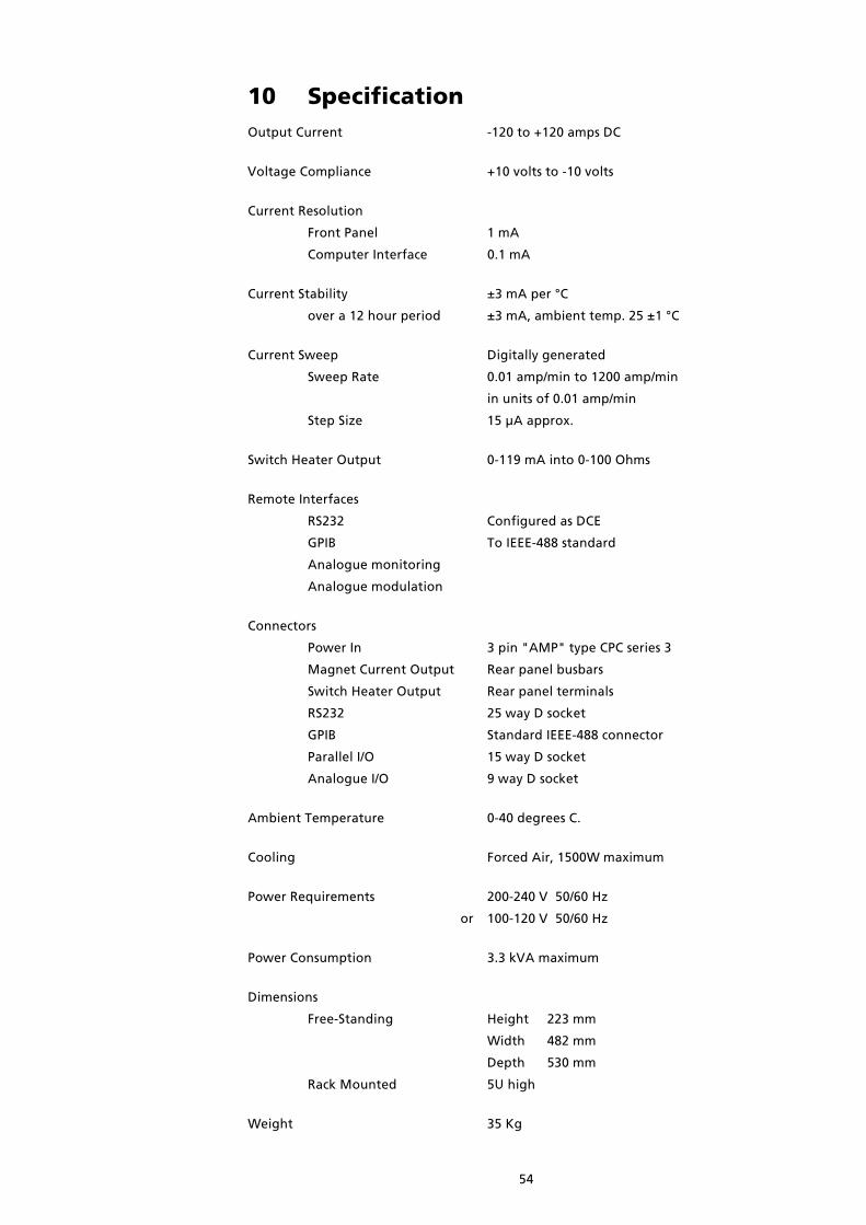
54
10 SpecificationOutput Current -120 to +120 amps DC
Voltage Compliance +10 volts to -10 volts
Current Resolution
Front Panel 1 mA
Computer Interface 0.1 mA
Current Stability ±3 mA per °C
over a 12 hour period ±3 mA, ambient temp. 25 ±1 °C
Current Sweep Digitally generated
Sweep Rate 0.01 amp/min to 1200 amp/min
in units of 0.01 amp/min
Step Size 15 µA approx.
Switch Heater Output 0-119 mA into 0-100 Ohms
Remote Interfaces
RS232 Configured as DCE
GPIB To IEEE-488 standard
Analogue monitoring
Analogue modulation
Connectors
Power In 3 pin "AMP" type CPC series 3
Magnet Current Output Rear panel busbars
Switch Heater Output Rear panel terminals
RS232 25 way D socket
GPIB Standard IEEE-488 connector
Parallel I/O 15 way D socket
Analogue I/O 9 way D socket
Ambient Temperature 0-40 degrees C.
Cooling Forced Air, 1500W maximum
Power Requirements 200-240 V 50/60 Hz
or 100-120 V 50/60 Hz
Power Consumption 3.3 kVA maximum
Dimensions
Free-Standing Height 223 mm
Width 482 mm
Depth 530 mm
Rack Mounted 5U high
Weight 35 Kg

55
11 Quick Reference Guide
11.1 Front Panel Controls
OUTPUT VOLTS Display power supply output voltage
CURRENT / FIELD Toggle the display between showing current (in amps) and the
equivalent field (in tesla).
MAGNET STATUS Display current (or field) in the magnet.
MAGNET STATUS Display trip current (or field), saved when voltage limiting.
+ SET POINT
SET RATE Display sweep rate.
To adjust use RAISE & LOWER.
SET POINT Display set point current (or field).
Adjust using RAISE, LOWER and CHANGE POLARITY.
CHANGE POLARITY Use with SET POINT.
HOLD Unclamp the power supply.
Stop the power supply from sweeping.
Clear fault conditions ("Hot" and QUENCH)
HOLD + RAISE Set FASt sweep rate profile.
HOLD + LOWER Set SLOw sweep rate profile.
GOTO ZERO Sweep power supply towards zero current.
GOTO SET Sweep power supply towards the SET POINT current.
HEATER Toggle the switch heater on and off.
If magnet persistent at different current to power supply, then
display 'MAGNET STATUS' and refuse to open switch.
LOC / REM Toggle Local (front panel) and Remote (computer) control.
RAISE Increase the value of a displayed variable.
LOWER Decrease the value of a displayed variable.
LOC / REM Enter test mode.
+ RAISE + LOWER

56
An Set Activity A0 hold, A1 goto set point, A2 goto zero, A4 clamp
Cn Set Control C0 local, C1 remote locked, C3 remote unlocked
Fnn Set Front Panel to Display Parameter see section 11.2
Hn Set Switch Heater: H0 off, H1 on, H2 force on
Inn Set Target Current (amps)
Jnn Set Target Field (tesla)
Mn Set Mode: M8 amps, M9 tesla
Pn Set Polarity
Qn Set Communications Protocol Q0 normal, Q4 high resolution
Rnn Read Display Parameter see section 11.2
Snn Set Current Sweep Rate (amps/minute)
Tnn Set Field Sweep Rate (tesla/minute)
Unn Unlock System Commands
V Read Version
Wnn Set Wait Interval
X Examine Status: XmnAnCnHnMmnPmn
Yn Load RAM Contents
Zn Dump RAM Contents
! Set ISOBUS Address
~ Store Data
Specialist Commands
a Read Auto-Run-Down Status
c Read Damping Parameter
d Read Damping Coefficient
e.. Set Damping Coefficient
g Read Hex Reading
h.. Set Hex Variable
r Read Parallel Interface Port
s.. Set Parallel Interface Port
x.. Set x Pointer
y.. Set y Pointer
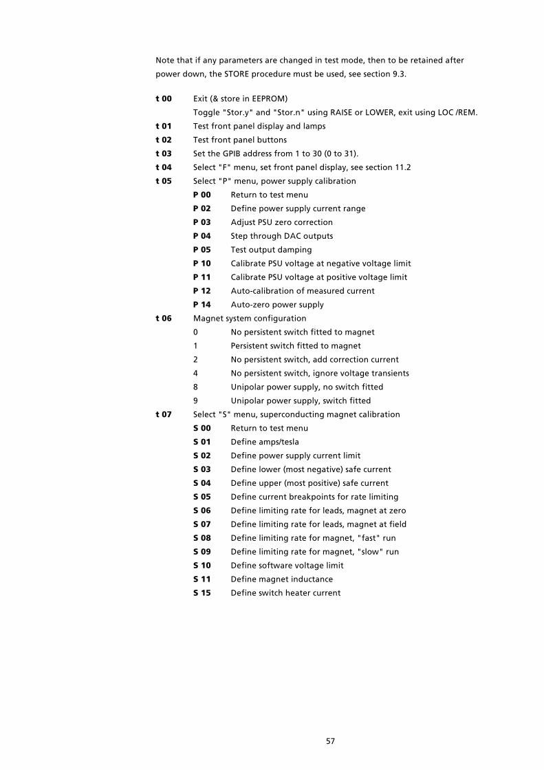
57
Note that if any parameters are changed in test mode, then to be retained after
power down, the STORE procedure must be used, see section 9.3.
t 00 Exit (& store in EEPROM)
Toggle "Stor.y" and "Stor.n" using RAISE or LOWER, exit using LOC /REM.
t 01 Test front panel display and lamps
t 02 Test front panel buttons
t 03 Set the GPIB address from 1 to 30 (0 to 31).
t 04 Select "F" menu, set front panel display, see section 11.2
t 05 Select "P" menu, power supply calibration
P 00 Return to test menu
P 02 Define power supply current range
P 03 Adjust PSU zero correction
P 04 Step through DAC outputs
P 05 Test output damping
P 10 Calibrate PSU voltage at negative voltage limit
P 11 Calibrate PSU voltage at positive voltage limit
P 12 Auto-calibration of measured current
P 14 Auto-zero power supply
t 06 Magnet system configuration
0 No persistent switch fitted to magnet
1 Persistent switch fitted to magnet
2 No persistent switch, add correction current
4 No persistent switch, ignore voltage transients
8 Unipolar power supply, no switch fitted
9 Unipolar power supply, switch fitted
t 07 Select "S" menu, superconducting magnet calibration
S 00 Return to test menu
S 01 Define amps/tesla
S 02 Define power supply current limit
S 03 Define lower (most negative) safe current
S 04 Define upper (most positive) safe current
S 05 Define current breakpoints for rate limiting
S 06 Define limiting rate for leads, magnet at zero
S 07 Define limiting rate for leads, magnet at field
S 08 Define limiting rate for magnet, "fast" run
S 09 Define limiting rate for magnet, "slow" run
S 10 Define software voltage limit
S 11 Define magnet inductance
S 15 Define switch heater current

58
11.2 Display ParametersThese numbers identify the display variables for the two computer interface commands,
Fnn and Rnn. The test mode, t 04, sets the front panel display using the same numbers.
Some parameters are marked E.R., if the computer interface has been set to extended
resolution mode, then the reply to the Rnn command includes an extra decade.
0 Demand current (output current) amp E.R.
1 Measured power supply voltage volt
2 Measured magnet current amp
3 Unused
4 Demand current (duplicate of R0) amp E.R.
5 Set point (target current) amp E.R.
6 Current sweep rate, amp / minute E.R.
7 Demand field (output field) tesla E.R.
8 Set point (target field) tesla E.R.
9 Field sweep rate, tesla / minute E.R.
10 DAC zero offset amp E.R.
11 Channel 1 freq./4
12 Channel 2 freq./4
13 Channel 3 freq./4
14 Demand current (duplicate of r0) amp E.R.
15 Software voltage limit volt
16 Persistent magnet current amp E.R.
17 Trip current amp E.R.
18 Persistent magnet field tesla E.R.
19 Trip field tesla E.R.
20 Switch heater current milliamp
21 Safe current limit, most negative amp
22 Safe current limit, most positive amp
23 Lead resistance, milliohm
24 Magnet inductance henry
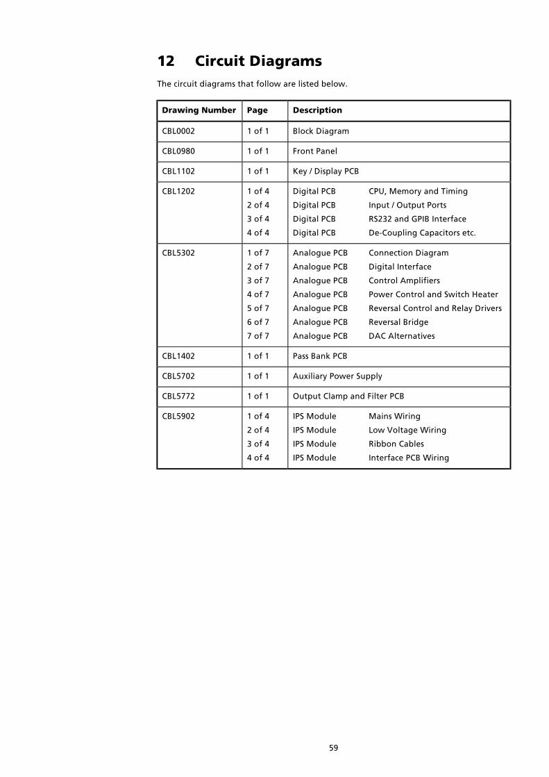
59
12 Circuit DiagramsThe circuit diagrams that follow are listed below.
Drawing Number Page Description
CBL0002 1 of 1 Block Diagram
CBL0980 1 of 1 Front Panel
CBL1102 1 of 1 Key / Display PCB
CBL1202 1 of 4
2 of 4
3 of 4
4 of 4
Digital PCB CPU, Memory and Timing
Digital PCB Input / Output Ports
Digital PCB RS232 and GPIB Interface
Digital PCB De-Coupling Capacitors etc.
CBL5302 1 of 7
2 of 7
3 of 7
4 of 7
5 of 7
6 of 7
7 of 7
Analogue PCB Connection Diagram
Analogue PCB Digital Interface
Analogue PCB Control Amplifiers
Analogue PCB Power Control and Switch Heater
Analogue PCB Reversal Control and Relay Drivers
Analogue PCB Reversal Bridge
Analogue PCB DAC Alternatives
CBL1402 1 of 1 Pass Bank PCB
CBL5702 1 of 1 Auxiliary Power Supply
CBL5772 1 of 1 Output Clamp and Filter PCB
CBL5902 1 of 4
2 of 4
3 of 4
4 of 4
IPS Module Mains Wiring
IPS Module Low Voltage Wiring
IPS Module Ribbon Cables
IPS Module Interface PCB Wiring

60

61
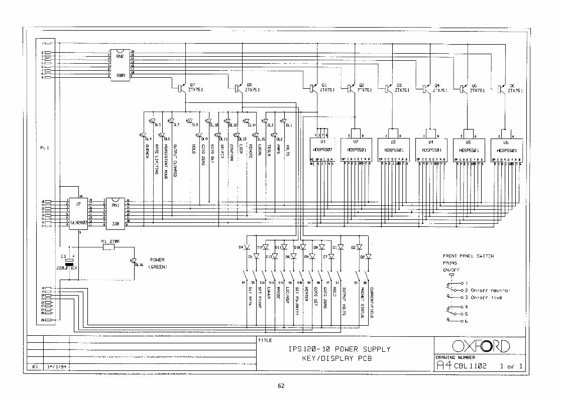
62

63

64

65

66
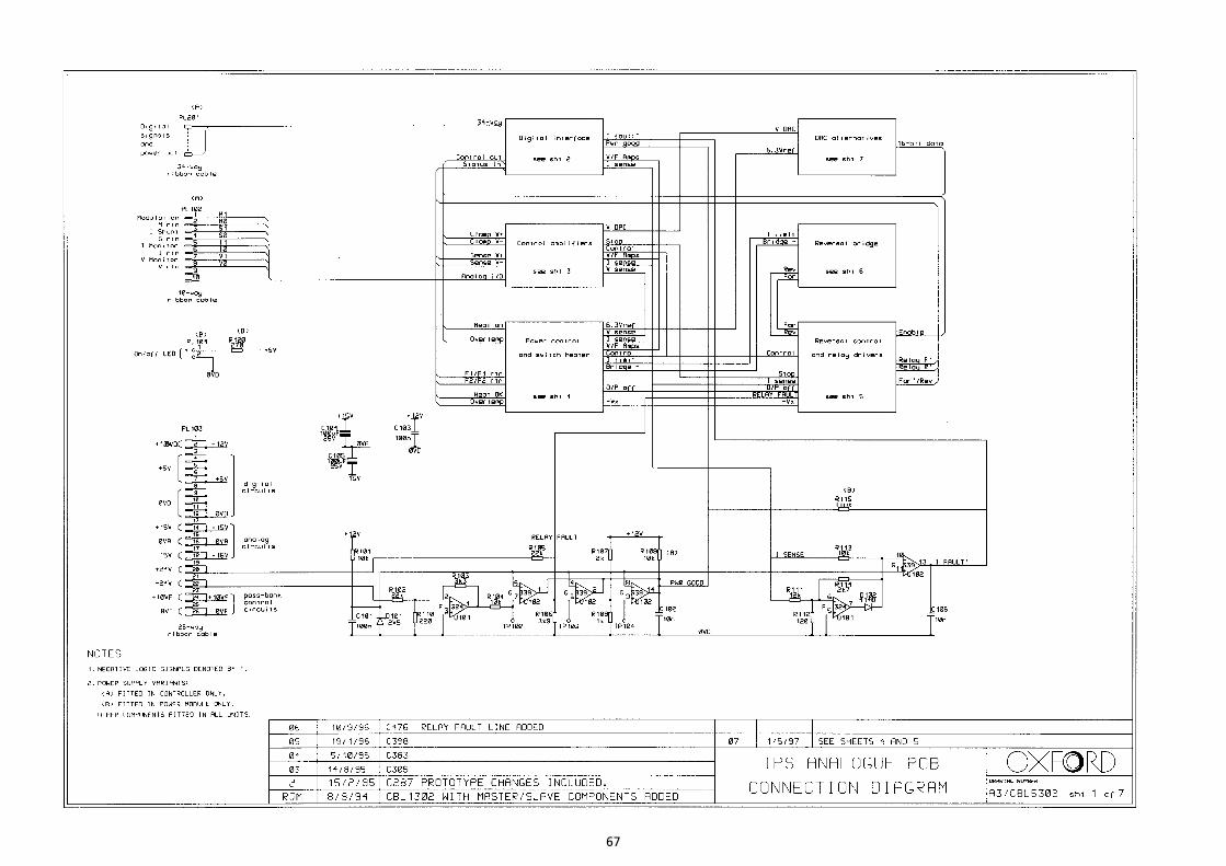
67

68
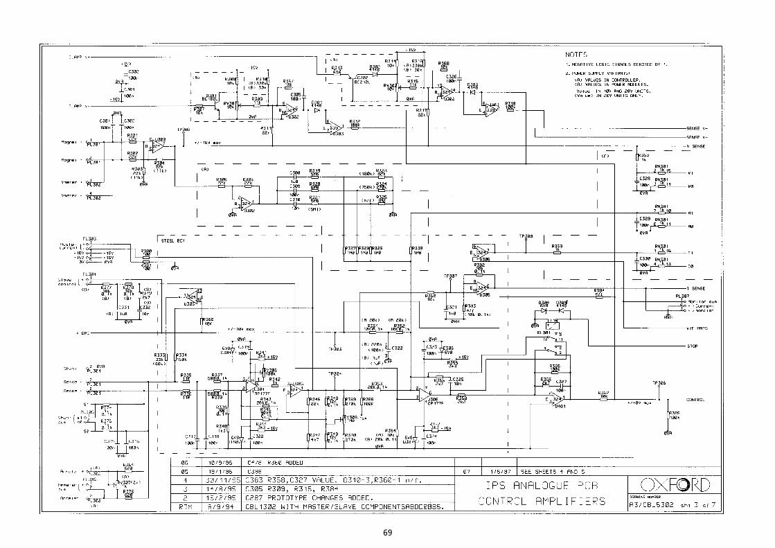
69
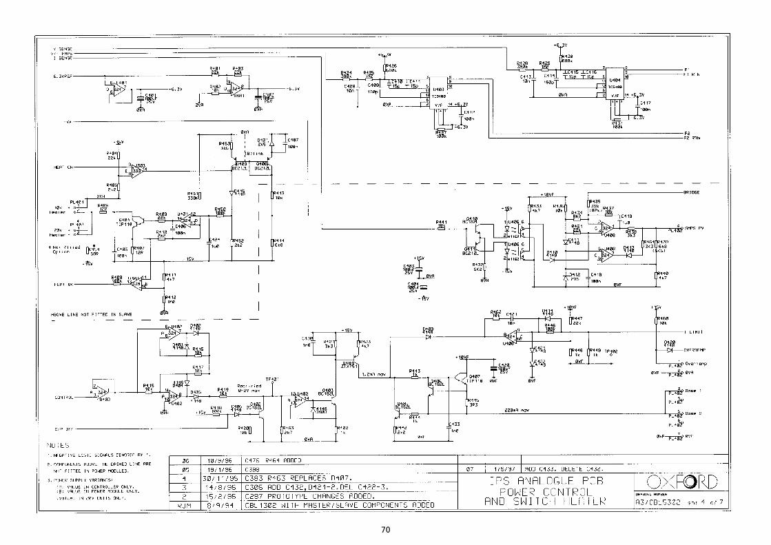
70

71
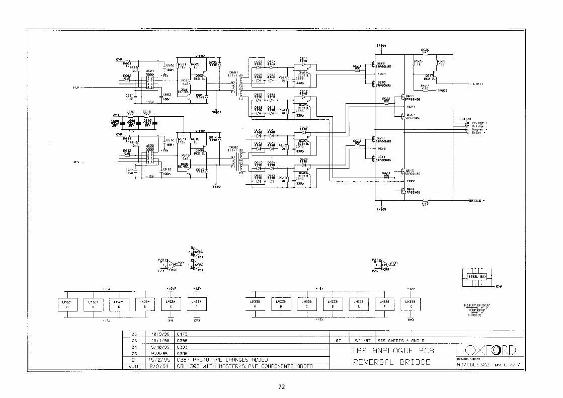
72

73

74

75

76
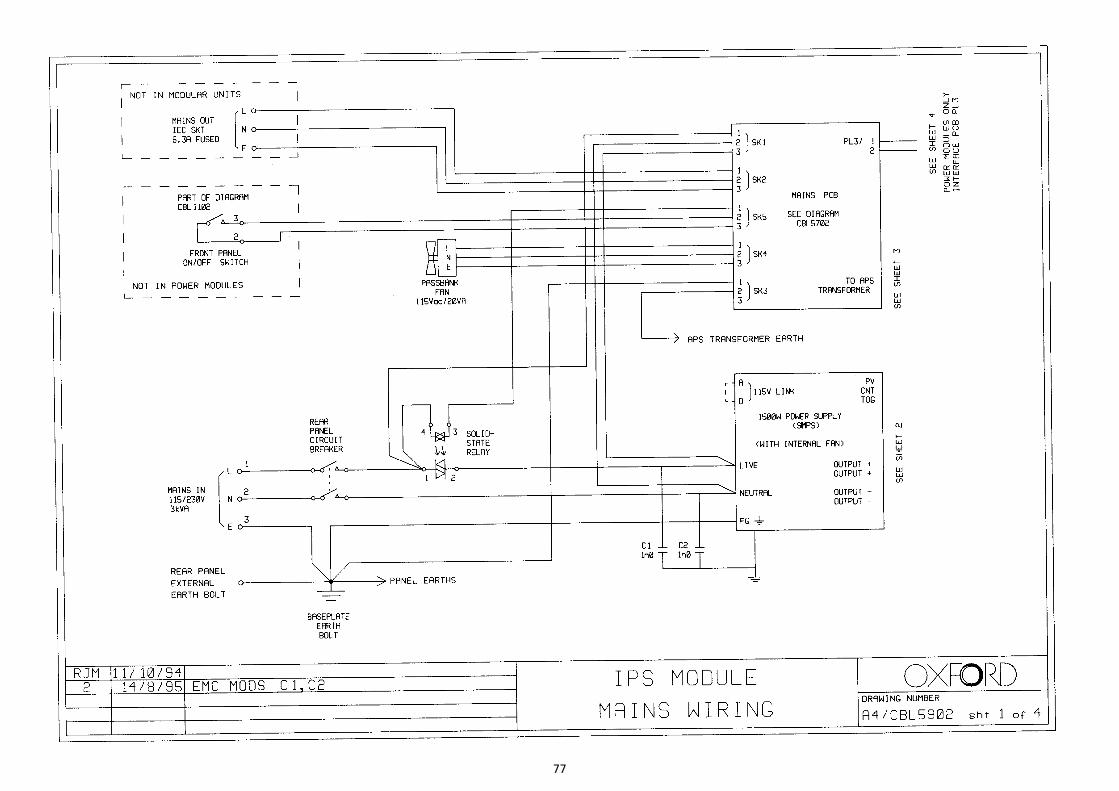
77

78

79

80