DOCUMENT RESUME ED 320 029 AUTHOR TITLE … Wiring is a ievision of MAVCC's 1983 wiring publication...
252
ED 320 029 AUTHOR TITLE INSTITUTION PUB DATE NOTE AVAILABLE FROM PUB TYPE EDRS PRICE DESCRIPTORS DOCUMENT RESUME CE 055 217 Taylor, Mark Residential Wiring. Mid-America Vocational Curriculum Consortium, Stillwater, Okla. 88 259p.; For related documents, see CE 054 849-850. Revised by Don Blasingame and Gary Flowers; edited by Jane Huston. Mid-America Vocational Curriculum Consortium, 1500 West Seventh Avenue, Stillwater, OK 74074 (order no. 100772: $11.00). Guides - Classroom Use Guides (For Teachers) (052) MF01 Plus Postage. PC Not Available from EDRS. Blueprints; *Building Trades; Competency Based Education; Educational Objectives; *Electrical Occupations; *Electrical Systems; *Electricity; *Housing Industry; Occupational Information; Postsecondary Education; Trade and Industrial Education; Troubleshooting IDENTIFIERS *Residential Wiring ABSTRACT The second in a series of three curriculum packages on wiring, these materials for a five-unit course were developed to prepare postsecondary students for entry-level employment in the residential wiring trade. The five units are: (1) blueprint reading and load calculations; (2) rough-in; (3) service; (4) trim out and troubleshooting; and (5) load center changes. The first section is designed to show teachers how to use the materials and includes an explanation of instructional elements; an instructional and task analysis for eacb unit; a list of tools, equipment, and materials; a glossary; and a list of 14 references. The instructional elements for the units include objectives, suggested activities, handouts, information sheets, transparency masters, assignment sheets, job sheets, tests, and test an-ers. Some elements, such as the information sheets, include diagrams and line drawings. (CML) ****************g***************k***************************It********** * Reproductions supplied by EDRS are the best that can be made * from the original document. **************1.ts******************g*************/:*********************
Transcript of DOCUMENT RESUME ED 320 029 AUTHOR TITLE … Wiring is a ievision of MAVCC's 1983 wiring publication...

ED 320 029
AUTHORTITLEINSTITUTION
PUB DATENOTE
AVAILABLE FROM
PUB TYPE
EDRS PRICEDESCRIPTORS
DOCUMENT RESUME
CE 055 217
Taylor, MarkResidential Wiring.
Mid-America Vocational Curriculum Consortium,Stillwater, Okla.88
259p.; For related documents, see CE 054 849-850.Revised by Don Blasingame and Gary Flowers; edited byJane Huston.
Mid-America Vocational Curriculum Consortium, 1500West Seventh Avenue, Stillwater, OK 74074 (order no.100772: $11.00).Guides - Classroom Use Guides (For Teachers) (052)
MF01 Plus Postage. PC Not Available from EDRS.Blueprints; *Building Trades; Competency BasedEducation; Educational Objectives; *ElectricalOccupations; *Electrical Systems; *Electricity;*Housing Industry; Occupational Information;Postsecondary Education; Trade and IndustrialEducation; Troubleshooting
IDENTIFIERS *Residential Wiring
ABSTRACTThe second in a series of three curriculum packages
on wiring, these materials for a five-unit course were developed toprepare postsecondary students for entry-level employment in theresidential wiring trade. The five units are: (1) blueprint readingand load calculations; (2) rough-in; (3) service; (4) trim out andtroubleshooting; and (5) load center changes. The first section isdesigned to show teachers how to use the materials and includes anexplanation of instructional elements; an instructional and taskanalysis for eacb unit; a list of tools, equipment, and materials; aglossary; and a list of 14 references. The instructional elements forthe units include objectives, suggested activities, handouts,information sheets, transparency masters, assignment sheets, jobsheets, tests, and test an-ers. Some elements, such as theinformation sheets, include diagrams and line drawings. (CML)
****************g***************k***************************It*********** Reproductions supplied by EDRS are the best that can be made* from the original document.**************1.ts******************g*************/:*********************

f:n0
CP
U.S. DEPARTMENT OF EDUCATON
Ca Once Educanonal Rissearcrt and IntororrnentED 'RONAL RESOURCES INFORMATION
cez . /us document nas Peen reproduced asCENTER (ERIC)
ru. rectrrred from tne person or OrGsmtanon= CI Msn Or Cnin Vs have been made to unprovecopulating ir.
CIAPosnts et new Or OpgniOn3statedinthISOOCU
reproduction auanty
men! do not necessarily represent otrIcsalOERI 0031D3n or t:01,CY
to
88.005725
"PERMISSION TO REPRODUCE THISMATERIAL IN MICROFICHE ONLYHAS BEEN GRANTED BY
4/:/'&5)41TO THE EDUCATIONAL
RESOURCESINFORMATION CENTER (ERIC)."
CN100772

North Dakota
South Dakota
3
RESIDENTIAL WIRING
Written by
Mark Taylor
Revised by
Don LlasingameGary Flowers
Edited by
Jane Huston
Developed by
The Mid-America Vocational Curriculum ConsortNm, Inc.
Board of Directors
Harley Schlichting, Missouri, ChairmanRon Mehrer, North Dakota, Vice Chairman
Joyce Sawatzky, Oklahoma, ParliamentarianJim Adams, Arkansas
Dorothy Horrell, ColoradoVernon Fennell, Iowa
Les Abel, KansasDavid Poston, LouisianaAnn Masters, Nebraska
Larry Zikmund, South DakotaRobert Patterson, Texas
Greg Pierce, Executive Director
CN100772 Teacher
4

c 1988 by the Mid-America Vocational Curriculum Consortium, Inc.
All rights reserved. No part of (his bookmay be reproduced in any form or by anymeans without written permission from the publisher.
Printed in the United States of America by theOklahoma State Department of Vocational-Technical EducationStillwater, OK 74074
Mid-America Vocational Curriculum Consortium, Inc.1500 West SeventhStillwater, Oklahoma 74074-4364

RESIDENTIAL WIRPNG
TABLE OF CONTENTS
Unit I: Blueprint Reading and Load Calculations 1
Unit II: Rough-In 39
Unit III: Service 109
Unit IV: Trim Out and Troubleshooting 161
Unit V: Load Center Changes 239

FOREWORD
Residential Wiring is a ievision of MAVCC's 1983 wiring publication of the same name. Thismanual is the second in a series of three wiring publications and picks up where the basicmanual ends and prepares the student for entry-level employment in the residential wiringtrade.
Basic Wiring is the first publication in the wirLig series and serves as the foundation for stu-dents enrolled in a wiring program. It is a prerequisite to either Residential Wiring or Commer-cial and Industrial Wiring. This series of publications should provide the flexibility thatinstructors need to meet the individual needs of their students and the community.
Commercial and Industrial Wiring, the third publication in the wiring series, includes the addi-tional technical knowledge and applications required for job entry in the commercial andindustrial wiring trade.
These publications were developed with the assistance of many individuals whc have exper-tise in various areas of the wiring trade. Some of these individuals represent professionalassociations and industry. Their assistance and devotion to this project is greatly appreciated.It should be emphasized that the student needs to be aware of professional trade associa-tions and take an active part in them as much as possible. The professional trade associa-tions, as well as vocational education, are an excellent avenue for continuing education withinthe electrical trade.
Every effort has been made to make these publications basic, readable, and by all means, us-able. Three vital parts of instruction have been intentionally omitted from these publications:motivation, personalization, and localization. Those areas are left to the individual instructorsand the instructors should capitaiL: em them. As these publications are used, it is hoped thatstudents performance will imp:ove and that students will be better able to assume a role inelectrical wiring.
Harley Schlichting, ChairmanBoard of DirectorsMid-America Vocational
Curriculum Consortium
Greg PierceExecutive DirectorMid-America Vocational
Curriculum Consortium
7

ACKNOWLEDGEMENTS
Appreciation is extended to those individuals who contributed their time and talent to thedevelopment of Residential Wiring.
The contents of this publication were planned and reviewed by:
Loren AmerineBill BarnesHarold BrownDaniel FrohbergTracy NaasMike PedersenClifford SchaeferRandy Wilson
Hoisington, KansasLittleton, ColoradoHope, ArkansasNorfolk, NebraskaKloten, North DakotaSheldon, IowaFt. VrJrth, TexasStillwater, Oklahoma
A special thank you goes to Stan Kaltwasser, commercial electricity instructor at Central Okla-homa AVTS Drumright, for providing his input and expertise in the planning and validationmeetings.
Appreciation is also extended to the technical artist, Donna Bellmon, and to members of theOklahoma State Vo-Tech Print Shop for their excellent service in printing the text.
The text was phototypeset in the Oklahoma State Vo-Tech Communications Center, and forher excellent contribution, a thank you goes to phototypesetter Stephanie Smola.
Thanks are also extended to Jane Huston, coordinator and editor of this project.
vii

USE OF THIS PUBLICATION
Instructional Units
Residential Wiring contains five units of instruction. Each instructional unit includes someor all of the basic components of a unit of instruction; performance objectives, suggestedactivities for teachers and students, information sheets, assignment sheets, job sheets, visualaids, tests, and answers to the Jests. Units are planned for more than one lesson or class per-iod of instruction.
Careful study of each instructional unit by the teacher will help to determine:
A. The amount of material that can be covered in each class periodB. The skills which must be demonstrated
1. Supplies needed2. Equipment needed3. Amount of practice needed4. Amount of class time needed for demonstrations
C. Supplementary materials such as pamphlets or filmstrips that must be orderedD. Resource people who must be contacted
Objectives
Each unit of instruction is based on performance objectives. These objectives state thegoals of the course, thus providing a sense of direction and accomplishment for the student.
Performance objectives are stated in two forms: unit objectives, stating the subject matterto be covered in a Lnit of instruction; and specific objectives, stating the student performancenecessary to reach the unit objective.
Since the objectives of the unit provide direction for the teachinglearning process, it isimportant fcr the teacher and students to have a common understanding of the intent of theobjectives. A limited number of performance terms have been used in the objectives for thiscurriculum to assist in promoting the effectiveness of the communication among all individuals using the materials.
Reading of the objectives by the student should be followed by a class discussion toanswer any questions concerning performance requirements for each instructional unit.
Teachers should feel free to add objectives which will fit the material to the needs of the stu-dents and community. When teachers add objectives, they should remember to supply theneeded information, assignment and/or job sheets, and criterion tests.

Suggested Activities for the instructor
Each unit of instruction has a suggested activities sheet outlining steps to follow in accom-plishing specific objectives. Duties of instructors will vary according to the particular unit;however, for best use of the material they should include the following: provide students withobjective sheet, information sheet, assignment sheets, and job sheets; preview filmstrips,make transparencies, and arrange for resource materials and people; discuss unit and spe-cific objectives and information sheet; give test. Teachers are encouraged to use any addi-tional instructional activities and teaching methods to aid students in accomplishing theobjectives.
Information Sheets
Information sheets provide content essential for meeting the cognitive (knowledge) objec-tives in the unit. The teacher will find that the information sheets serve as an excellent guidefor presenting the background knowledge necessary to develop the skill specified in the unitobjective.
Students should read the information sheets before the information is discussed in class.Students may take additional notes on the information sheets.
Transparency Masters
Transparency masters provide information in a special way. The students may see as wellas hear the material being presented, thus reinforcing the learning process. Transparenciesmay present new information or they may reinforce information presented in the informationsheets. They are particularly effective when identification is necessary.
Transparencies should be made and placed in the notebook where they will be immediatelyavailable for use. Transparencies direct the class's attention to the topic of discussion. Theyshould be left on the screen only when topics shown are under discussion.
Assignment Sheets
/Assignment sheets give direction to study and furnish practice for paper and pencil activi-ties t.) develop the knowledge which is a necessary prerequisite to skill development. Thesemay be given to the student for completion in class or used for homework assignments.Answer sheets are provided which may be used by the student and/or teacher for checkingstudent progress.
Job Sheets
Job sheets are an important segment of each unit. The instructor should be able to demon-strate the skills outlined in the job s .ets. Procedures outlined in the job sheets give directionto the skill being taught and allow both student and teacher to check student progress towardthe accomplishment of the skill. Job sheets provide a ready outline for students to follow ifthey have missed a demonotration. Job sheets also furnish potential employers with a pictureof the skills being taught and the performances which might reasonably be expected from aperson who has had this; training.
1

Test and Evaluation
Paper-peucil and performaoce tests have been constructed to measure student achieve-ment of each objective listed in the unit of instruction. Individual test items may be pulled outand used as a short test to determine student achievement of a particular objective. This kindof testing may be used as a daily quiz and will help the teacher spot difficulties being encoun-tered by students in their efforts to accompI:sh the unit objective. Test items for objectivesadded by the teacher should be constructed and added to the test.
Test Answers
Test answers are provided for each unit. These may be used by the teacher and/or studentfor checking student achievement of the objectives.
xi

RESIDENTIAL WIRING
INSTRUCTIONAL TASK ANALYSIS
JOB TRAINING: What the RELATED INFORMATION: WhatWorker Should Be Able to Do the Worker Should Know
(Psychomotor) (Cognitive)
UNIT I: BLUEPRINT READING AND LOAD CALCULATIONS
1. Terms and definitions
2. Blueprint symbols
3. Electrical symbols
4. Types of lines
5. Information commonly found in blue-print specifications
6. Minimum requirements for residentialoutlets
7. Calculating circuit loads and voltagedrop
8. Draw receptacle and lighting outlets ofa floor plan
9. Determine general lighting loads
10. Determine small appliance and laun-dry loads
11. Determine total connected load plustotal demand load of a dwelling
12. Locate required receptacle and light-ing outlets on a house plan
xiii 1 2

JOB TRAINING: What the RELATED INFORMATION: WhatWorker Should Be Able to Do the Worker Should Know
(Psychomotor) (Cognitive)
UNIT II: ROUGH-IN
10. Locate receptacle, switch, and lightingoutlets along a floor line and the ceil-ing on a blueprint
11. Locate receptacle outlets alongkitchen cabinets
12. Install a device box when given cabinetheight and wall covering
13. Install a lighting outlet box when givenceiling covering thickness
14. Wire a switch controlled split-wiredreceptacle
15. Wire a receptacle fed from a lightingoutlet through a single pole switch
16. Wire a receptacle fed from a lightingoutlet through a three-way switch
17. Wire a four-way switching situationwith the supply entering the lightingoutlet box
xiv
1. Terms and definitions
Locations where at least one recepta-cle outlet is required
3. Planning techniques when placingboxes on plans
4. Accepted heights for boxes
5. Procedure for installing boxes in exte-rior walls
6. Box extensions for noncombustibleand combustible wall surfaces
7. Common methods of finding room cen-ters
8. Required outlets
9. Rules for electrical installations
13

JOB TRAINING: What the RELATED INFORMATION: WhatWorker Should Be Able to Do the Worker Should Know
(Psychomotor) (Cognitive)
UNIT III: SERVICE
10. Calculate service size and minimumnumber of circuits
11. Install an overhead raceway with serv-ice entrance conductors to a meterbase
12. Connect meter base assembly to loadcenter or panel
13. Install an underground service (lateral)raceway with conductors to a meterbase
xv
1. Terms and definitions
2. Clearances for service drop conduc-tors
3. Service digconnects
4. Facts that should be known beforeservice installation is started
5. Parts of a service entrance
6. Types of grounding electrodes
7. Grounding electrode conductor instal-lations and sizes
8. Short circuit protection at serviceequipment
9. Surge protection
1'

JOB TRAINING: What the RELATED INFORMATION: WhatWorker Should Be Able to Do the Worker Should Know
(Psychomotor) (Cognitive)
UNIT IV: TRIM OUT AND TROUBLESHOOTING
1. Terms and definitions
2. Common residential receptacle typesand cover plates
3. Common residential switch types andcover plates
4. Common residential fixture locations
5. Appliance classifications
6. Requirements for appliance discon-nect means
7. Grounding requirements for appli-ances
8. Parts of a duplex grounding typereceptacle
9. Parts of an equipment grounding sys-tem
10. Steps for panel trim out
11. Troubleshooting procedures
12. Install a duplex grounding type recep-tacle
13. Install a range or dryer receptacle
14. Install a multi-circuit split-wired duplexgrounding type receptacle
15. Wire a receptacle fed from a lightingoutlet through a single pole switch
16. Connect a supply cord to a free stand-ing range
17. Install a fixed appliance equipped witha pigtail to a branch circuit
18. Install a fusible safety switch for an air-conditioning condenser
19. Troubleshoot an electrical systemproblem
xvi

JOB TRAINING: What the RELATED INFORMATION: WhatWorker Should Be Able to Do the Worker Should Know
(Psychomotor) (Cognitive)
UNIT V: LOAD CENTER CHANGES
1. Terms and definitions
2. Types of load centers
3. Reasons for load center changes
4. Ways to increase service size on anexisting dwelling
5. Procedures for changing existing serv-
6. Replace an existing interior flushmount load center
7. Install a rainproof load center to sup-plement an existing interior load center
ice
xvii-i

RESIDENTIAL WIRING
TOOLS, EQUIPMENT, AND MATERIALS LIST
Auxiliary lightingAwlBar hangerBulb, 120 voltBushingsCableCable clamp, 3/8"Cable connectorCircuit testerCopperDevice boxDrill motorDrop clothDuplex grounding type receptacleElectrical supplyExtension cordFastenersFeeder wireFixed appliance with pigtailFolding ruleFree standing rangeGFIHacksaw bladeIncandescent bulb, 120 voltKeyhole sawKnockout cutter setLeather glovesLight socketLoad centerLocknutsMeter base
--
Mock up wallNut driver setOctagon boxPencil16 penny nailsPlasterboard nailsPocket knifePortable GF1Pouch toolsPVC couplingPVC 90° elbowPVC male adapterRacewayRaintight fusible, rigid metal conduitRigid nonmetallic tubingRuleSafety glassesSafety switchService entrance capSingle pole switchStaplesStud wallSwitch, three-waySwitch, four-wayTapping screws, metalVoltmierVolt-ohm-ammeterWire connectorsWire strippersWood bit

RESIDENTIAL WIRING
GLOSSARY
Air - conditioning condenser Refrigeration equipment that sits outside a residential dwellingand is used to remove heat from refrigerant; usually contains a hermetically sealed compres-sor
Appliance Utilization equipment, generally other than industrial, normally built in standard-ized sizes of types, which is installed or connected as a unit to perform one or more funcitonssuch as clothes washing, air conditioning, food mixing, or deep frying
Appliance branch circuit A branch circuit supplying energy to one or more outlets to whichappliances are to be connected
Backsplash That portion of a wall behind the kitchen cabinet, starting at the counter topand ending at the bottom of the wall hung cabinets
Blueprint Copy of the original detailed drawings of a structure
Blueprint lines A set of conventional symbols to depict an object
Box center Midpoint on a box's vertical dimension
Box set out Distance that the box extends past the stud
Branch circuit The circuit that extends from the last overcurrent protection device to theoutlets
Cable clamp Piece of equipment used to secure cables
Circuit breaker Automatic overcurrent device that trips on overloads or shorts and is reset-table
Cutout box An enclosure designed for surface mourr .a and having swinging door or cov-ers secured directly to and telescoping with the walls of the box proper
Device Unit of an electrical system which is intended to carry but not utilize electricalenergy
Disconnecting means A device, or group of devices, or other means by which the conduc-tors of a circuit can be disconnected from their source of supply
Duplex grounding receptacle A single device with two grounding type receptacles
Dwelling One or more rooms used for eating, living, and sleeping with permanent provi-sions for cooking and sanitation
Feeder circuit All circuit conductors between the service equipment or the source of a sep-arately derived system and final branch circuit overcurrent device
8

Feed through The Lse of a box for spIlcing or rerouting conductors to get to another loca-tion
Flush Even with the surface
Full load amps (FLA.) Amaperage at which equipment is designed to operate
Grounding electrode conductor Conductor used to connect the grounding electrode to theequipment grounding conductor and/or the grounded conductor of the circuit at the service
Habitable Suitable for people to occupy or live in
Individual branch circuit Branch circuit that supplies only one piece of utilization equip-ment
Life sustaining medical equipment Equipment necessary to keep patients alive
Lighting outlet An outlet intended for the direct connection of a lampholder or light fixture
Line leg Conductor that supplies electrical energy to a switch
Load center A factory assembled metal cabinet consisting of fuses or circuit breakers forovercurrent protection of electrical wiring
Multiple receptacle Single device with two or more receptacles
Outage Period during which no current is available to circuits in a residential dwelling
Overcurrent protection Weak link in the circuit that limits the amperage to a specifiedamount
Pigtail Splicing technique that leaves an accessible conductor for termination at a device,load, or grounding terminal
Poles Current carrying conductors, both grounded and ungrounded, on a receptacle
Premises wiring The interior and exterior wiring including power, lighting, control and sig-nal circuits together with associated hardware, fittings, and wiring devices
Receptacle connecting fin Detachable design feature that makes terminals common con-nections
Receptacle outlets An outlet where one or more receptacles are installed
Roof flashing Protective equipment used where the mast emerges from the roof or eave toseal around the raceway and protect against water damage
Room center Point in a room that is equal distance from parallel walls
Service Where power is metered or is first attached to the structure
Service cable Service conductors made up in the form of a cable
19

Service conductor: Supply conductors that extend from the street main or from transform-ers to the service equipment of the premises to be supplied
Service drop Power conductors coming into building from power company
Service entrance The conductors and equipment for delivering electricity from the supplysystem to the wiring system of the premises served
Service entrance conductors, underground system Service conductors betweer the termi-nals of the service equipment and a point usualiy outside the building, clear of building walls,where joined by tap or splice to the service drop
Service equipment Necessary equipment, usually consisting of a circuit breaker or fusesand their accessories, located near the point of entrance of supply condsors to a building orother structure, or an otherwise defined area, and intended to constitute the main control andmeans of cutoff of the supply
Service lateral Underground service conductors between the street main, including any ris-ers at a pole or other structure or from transformers and the first point of connection to theservice entrance conductors in a terminal box or meter or other enclosure with adequatespace inside or outside the building wall
Service mast That portion of a service raceway that extends through a roof or eave
Service raceway Raceway that encloses the service entrance conductors
Short circuit Unintentional contact of a conductor
Single receptacle A single contact device with no other contact device on the same yoke
Specifications A detailed set of written insiluctions which explain the drawing and becomepart of the contract
Split-wired receptacle Receptacle that has had a connecting fin removed for remote controlor separate circuit connections
Strap or yoke Metal strip containing ne or more devices
Switch Device used to open or transfer circuit direction
Switch leg Conductor that carries electrical energy from the switch to the load
Switch loop Conductors between light and switch when supply enters the light
Symbol An arbitrary sign that has been standardized and is used to represent an object,quantity or method
Terminal Point of attachment for conductors
Tile cap Final tile in a ceramic backsplash when the tile is terminated at some point up thewall
20 /

Traveler Transfer conductors in a switching situation; they are used between 3-ways and 4-ways
Trim out Final stage in a residential wiring project; involves devices and plates, connectingand securing equipment, hanging fixtures, and testing the system
Troubleshooting The systematic diagnosis of a malfunction
Voltage drop A reduction in available voltage at the end of a circuit
Volt ampere Voltage multiplied times amperage
Wires Current carrying conductors and grounding conductors
e

RESIDENTIAL WIRING
REFERENCES
Buss Fuses Full Line Condensed Catalog, January 1985. St. Louis, MO: Bussman Division,McGraw Edison Company.
Designing Electrical Systems. American Technical Publishers, Homewood, IL 60430.
D Digest 1987. Palatine, IL: Square D Company.
Earl, John T. Electrical Wiring Design and Application. Englewood Cliffs, NJ: Prentice Hall,1983.
Foley, Joseph H. Electrical Wiring Fundamentals. New York: Gregg, McGraw-Hill Book Com-pany, 1981.
Gebert, Kenneth L. Blueprint Reading. Ninth Edition. Alsip, IL: American Technical Publica-tions, Inc., 1983.
Gray, Elliott C.; R. Bailey; and E. Melbourne. Electrical Construction and Maintenance Tech-niques.Englewood Cliffs, NJ; Prentice Hall, 1986.
Holzman, Harvey N. Modern Resideriial Wiring. South Holland, IL: Goodheart-Willcox Com-pany Inc., 4986.
Hunzicker Brothers Cata!,:,s Oklahoma City, OK.
Pass and Seymore -- Wiring DPV1C6.; Catalog #486. Syracuse, NY.
Richter, Herbert R and W. Creighton Schwan. Practical Electrical Wiring. Thirteenth Edition.Englewood Cliffs, NJ: Prentice Hall, 1984.
Stallcup, James G. Designing Electrical Systems. Homewood, IL: American Technical Pub-lishers, Inc., 1985.
Taylor, Mark. Residential Wiring. Revised. Stillwater, OK: Mid-America Vocational CurriculumConsortium, 1983.
The National Electrical Code Handbook. Fourth Edition. Quincy, MA: National Fire ProtectionAssociation, 1986.
22xxv

RW-1
BLUEPRINT READING AND LOAD CALCULATIONSUNIT I
UNIT OBJECTIVE
After completion of this unit, the student should be able to interpret blueprint drawings, iden-tify symbols, and perform load calculations from the ihformation provided in blueprint draw-ings and specifications. Competencies will be demonstrated by completing the assignmentsheets and the unit test with a minimum score of 85 percent.
SPECIFIC OBJECTIVES
After completion of this unit, the student should be able to:
1. Match terms related to blueprint reading and load calculations with their correctdefinitions.
2. Identify blueprint symbols used in residential drawings.
3. Match electrical symbols with their correct descriptions.
4. Match types of lines with their pictures arr. 'ascriptions.
5. List kinds of information commonly found in blueprint specifi' 'tions.
6. Complete statements concernIno minimum requirements for res.dential outlets.
7. Calculate circuit loads and voltage drop of a dwelling.
8. Draw receptacle and lighting outlets on a floor plan. (Assignment Sheet #1)
9. Determine general lighting loads. (Assignment Sheet #2)
10. Determine small appliance and laundry loads. (Assignment Sheet #3)
11. Determine total connected load plus total demand load of a dwelling. (AssignmentSheet #4)
12. Locate required receptacle and lighting outlets on a house plan. (AssignmentSheet #5)
23

BLUEPRINT READING AND LOAD CALCULATIONSUNIT I
SUGGESTED ACTIVITIES
A. Obtain additional materials and/or invite resource people to class to supplement/rein-force information provided in this unit of instruction.
(NOTE: This activity should be completed prior to the teaching of this unit.)
B. Provide students with objective sheet.
C. Discuss unit and specific objectives.
D. Provide students with information and assignment sheets.
E. Discuss information and assignment sheets.
F. Integrate the following activities throughout the teaching of this unit:
1.
from local contractors.Collect and distribute to the class a number of blueprint and specification plans
2. Plan for and invite a local contractor to visit the classroom and discuss the read-ing of blueprints and their importance in the job.
3. Plan for and invite a local representative of the electrical inspection authority tovisit the classroom to discuss the local code restrictions ana how they affect theload calculations derived from blueprint and specification plans.
4. Have the students organize into separate groups and have each group design anddraw, to scale, a room or section of a house plan.
EXAMPLE: Group #1 will design ancidraw the kitchen dining room area of thehouse plan complete with symbols and dimensions. Group #2 willdesign and draw the master bedroom and master bath area. Group#3 will desigr and draw the guest bedroom and hall bathroom area.Group #4 will design and draw the living room and garage area. Allgroups should draw their areas to scale and provide necessary sym-bols and specifications. A completed drawing may then be assem-bled and load calculations made from the composite drawing andspecifications.
5. Obtain slides and films or video presentations related to blueprint reading andload calculation to show to the class.
6. Make copies of Handout #1 to distribute to class. Handout #1 will also serve as theanswer sheet to Assignment Sheet #5.
7. Meet individually with students to evaluate their progress through this unit ofinstruction, and indicate to them possible areas for improvement.

4
SUGGESTED ACTIVITIES
G. Give test.
H. Evaluate test.
I. Reteach if necessary.
REFERENCES USED iN WRITING THIS UNIT
A. Gebert, Kenneth L. Blueprint Reading. Ninth Edition. Alsip, IL: American Technical Pub-lications, Inc., 1983.
B. Taylor, Mark. Residential Wiring. Revised. Stillwater, OK: Mid-America Vocational Curric-ulum Consortium, 1983.
C. The National Electrical Code Handbook. Fourth Edition. Quincy, MA: National Fire Pro-tection Association, 1986.
25

RW-5
BLUEPRINT READING AND LOAD CALCULATIONSUNIT I
HANDOUT #1 - ELECTRICAL: FLOOR PLAN
(NOTE: Floor plan appears on back of this page.)
26

BEDROOM 1
Qs
Cr
1I/
///e
BEDROOM 2
P
BATH
ci-)
e.
-;3si1 III
at)
t 3
I ARCH1 S3 53-- . ...1 ,
I ,e
LAUNDRY
9SI di)) % mv
1 `,
BEDROOM 3
I
et.
S
ACCORDION-. ENV*
3QKITCHEN ...0e . .-.
....
..."" S/
1DINING ROOM \
r I1r
54
®
e/
LI
ENTRY
II tI i.. III
`,I
I II. .
Sow .....
41,
el
3- // '"".
S3t1
''' ... . jP4
ao
LIVING ROOM
/
.
V,
ELECTRICAL FLOOR PLAN SCALE Vs" = 1'
28
0)

A
BLUEPRINT READING AND LOAD CALCULATIONSUNIT I
INFORMATION SHEET
I. Terms and definitions
A. Blueprint Copy of the original detailed drawings of a structure
B. Blueprint lines A set of conventional symbols to depict an object
C. Branch circuit The circuit that extends from the last overcurrent protec-tion device to the outlets
D. Dwelling One or more rooms used for eating, living, and sleeping withpermanent provisions for cooking and sanitation
E. Feeder circuit All circuit conductors between the service equipment orthe source of a separately derived system and final branch circuit overcur-rent device
(NOTE This circuit originates at the service equipment and extends to thesubpanel.)
F. Lighting outlet An outlet intended for the direct connection of a lamp-holder or light fixture
G. Receptacle outlets An outlet where one or more receptacles are installed
H. Service entrance The conductors and equipment for delivering electricityfrom the supply system to the wiring system of the premises served
I. Specifications A detailed set of written instructions which explain thedrawing and become part of the contract
J. Symbol An arbitrary sign that has been standardized and is used to rep-resent an object, quantity, or method
K. Voltage drop A reduction in available voltage at the end of a circuit
II. Blueprint symbols used in residential drawings
A. Plumbing
L
nx1. Showers
[
2 9
2. Built-in bathtub
RW-7

I
INFORMATION SHEET
EC
3. Built-in lavatories 4. Single bowl 5. Double bowlsink sink
6. Shower heads
8. Laundry tubs
7. Furnace(designate fueland capacity)
9. Water '-leater(designate capacityand fuel)
30

B. Appliances
$
INFORMATION SHEET
1
ci DVSI I1 1
11
1. Washer and dryer 2. Freestanding and built-indishwashers
REF
) (0 00 03. Refrigerator 4. Freestanding range
0 00 0)
0 000 --IT
+++
5. Drop-in range 6. Surface cook top
1
1
7. Built-in oven
31
t
RW-9

10
INFORMATION SHEET
C. Structural symbols
II
1. Plan view of exterior door in wood frame wall
I I1
2. Plan view of exterior sliding door in wood frame wall
3. Plan view of exterior door in masonry veneer wall
6zz# `IT-mzzJ
4. Plan view of exterior sliding door in masonry veneer wall
5. Plan view of interior hinged door
6. Plan view of interior pocket door
32

INFORMATION SHEET
1
7. Single window in frame wall
8. Multiple windows in frame wall
E
9. Plan view of double hung window in frame wall
III. Electrical symbols
A. Convenience outlets
Ceiling outlet
WP
es
Fluorescent fixture
Junction box
Convenience outlet other than duplex1=single, 3=triplex, etc.
Weatherproof convenience outlet
Range outlet
Switch and convenience outlet
Duplex receptacle
Duplex receptacle split wired

12
®
INFORMATION SHEET
120/240, 14) combination receptacle
Floor outlet (attach additional symbol for recept. tel., etc.)
Special outletas noted
3@ 240V, 4W, 3P receptacleamps as noted
240V, 3W, 2P receptacleamps as noted
i_ Ground
F; FuseLlt
I)Circuit breaker
B. Switch outlets
S Single pole switch
S2 Double pole switch
S3 Three-way switch
S4 Four-way switch
SD Dimmer switch
SK Key operated switch
S, Switch and pilot light
Smc Momentary contact switch34
RW-13
INFORMATION SHEET
0 Thermostat
0 Humidistat
C. Panels, circuits, and miscellaneous
ille Lighting panel
M Power panel
Branch circuit; concealed in ceiling or wall
IMINIIMIIII
IV. Types of lines
Branch circuit; concealed in floor
Branch circuit; exposed
Home run to panel board; indicate numoer of circuits by num-ber of arrows.
Feeders
A. Object lines ( ) Show the main outline of the build-ing including exterior walls, interior partitions, porches, patios, driveways,and interior walls; these lines should be the outstanding lines on a drawing
B. Dimension lines ( t ) Thin unbroken lineswhich building dimensions are placed upon
C. Extension lines ( ) Extend, but do not touchthe object lines and permit dimension lines to be drawn between them
D. Hidden lines ( ) Short dashes used toshow lines that are not visible from that view
E. Center lines ( ) A series of short andlong dashes used to designate the center of doors, windows, and circlesand to provide a reference point for dimensioning
1\CF. Break lines (
--i\C) Used when an area can-
not or should not be drawn entirely
G. Leaders ( -aisr"---- ) Used to connect a note or dimension to a partof the buiiding
-3

14
INFORMATION SHEET
V. Information commonly found in blueprint specifications
A. Sizes
B. Types and quality of bulls:ling materials
C. Methods of construction
D. Material lists
(NOTE: This can include electrical lists as supplied by the electrical con-tractor in bids to the general contractor)
E. Owner's name and address
F. Contractor's name and address
G. Location of new structure
H. Completion date
I. Contractor's bid
J. Guarantees
K. Blueprint number
VI. Minimum requirements for residential outlets
A. Receptacles Installed so that no point along the floor line in any wallspace is more than 6 feet from an outlet
(NOTE: This is one minimum requirement. For other requirements see NECArt: 210.52.)
B. Switches Located so that they may be operated from a readily accessi-ble place
(NOTE: Install opposite hinge side of door. Other minimum requirements forswitches are covered in NEC Art: 380.)
C. Lighting At least one wall switch controlled lighting outlet shall beinstalled in every habitable room, halls, stairways, attached garages, bath-rooms, and outdoor entrances to residences
(NOTE: Other lighting outlet roquiremer covered in NEC Are: 210-70.)
36

..1.1011111,
RW-15
INFORMATION SHEET
VII. Calculating circuit loads and voltage drop of a dwelling
A. Branch circuits All branch circuit loads of a dwelling may be groupedinto one of three categories: (1) general lighting load, (2) small applianceand laundry load, and (3) special appliance load.
1. General lighting load To determine the general lighting load, multply 3 volt amps (watts) times the total square foot area of the dwell-ing unit.
(NOTE: NEC Art: 220-3[b] Table list the unit load required per squarefoot.)
2. Small appliance and laundry load The small appliance and laun-dry loads are figured at 1,500 volt-amps (watts) for each two wire cir-cuit.
(NOTE: NEC Art: 220.16 lists requirements for small appliance andlaundry circuits.)
3. Special appliance load The special appliance loads are deter-mined by the kilowatt rating listed on the nameplate.
(NOTE: NEC Art: 220-3 and 220-10[a] list requirements for specialappliance loads.)
B. Feeder circuits (subpanels) The computed load for the feeders shall notbe less than the sum of the loads on the branch circuits supplied.
(NOTE: NEC Art: 220-10 covers feeder calculations.)
C. Total load (service) All loads in a dwelling are not used simultaneously orfor extended periods of time. The application of demand factors will pro-duce lower total demand loads. Lower demand loads requlle small serviceentrance conductors, resulting in less material cost for the job.
(NOTE: Demand factors for dwelling loads are listed in NEC Art's: 220-11[general lighting and receptacle load], 220-17 [fixed appliance load], 220-18[dryer load], and 220.19 [range load].)
D. Voltage drop The formula for calculating voltage drop is,
VD= 2 xLxRxl1000
VD = Voltage Drop
L = One way length of circuit in feet
R = Conductor resistance in ohms per 1000 feet
(NOTE: See Chapter 9, Table 8 of the NEC.)
I = Load current (amperes)
37

BLUEPRINT READING AND LOAD CALCULATIONSUNIT I
ASSIGNMENT SHEET #1 - DRAW RECEPTACLE ANDLIGHTING OUTLETS ON A FLOOR PLAN
NAME SCORE
Directions: Using electrical symbols, draw locations of receptacle outlets and lighting outletsfor the floor plan below. Refer to NEC Art: 210-52 for minimum spacing and location.
T
CIP
12 ft.10 Closet --awl 2 ftil
2 3
12'
RW-17

BLUEPRINT READING AND LOAD CALCULATIONSUNIT I
ASSIGNMENT SHEET #2 - DETERMINE GENERAL LIGHTING LOADS
NAME SCORE
Directions: List the general lighting loads for the following dwellings. Use NEC Art: 220-3(b) todetermine general lighting load minimum requirements. Show all computations in space pro-vided.
1. 3200 sq. ft. with no garage.
2. 2750 sq. ft. with no garage.
3. 4100 sq. ft. including a 20 ft. x 24 ft. garage.
39
RW-19

RW-21
BLUEPRINT READING AND LOAD CALCULATIONSUNIT I
ASSIGNMENT SHEET #3 DETERMINE SMALLAPPLIANCE AND LAUNDRY LOADS
NAME SCORE
Directions: Calculate the small appliance and laundry loads for the dwellings below. Use NECArt's: 220-16(b) and 220-16(c) to determine minimum requirements. Show all computations inspace provided.
1. A single family dwelling with one kitchen area and one laundry area. The specificationscall for minimum circuits.
2. A single family dwelling with one kitchen area and one laundry area. The specificationscall for four circuits in the kitchen area and one circuit in the laundry area.
40

RW-23
BLUEPRINT READING AND LOAD CALCULATIONSUNIT I
ASSIGNMENT SHEET #4 - DETERMINE TOTAL CONNECTED LOADPLUS TOTAL DEMAND LOAD OF A DWELLING
NAME SCORE
Directions: Calculate the total connected load for the dwelling described below. Next applyappropriate demand factors to determine the total demand load.
(NOTE: NEC Art: 220-11 and accompanying Table will providJ proper demand percentage infor-mation.)
2400 Sq. Ft. Dwelling
Dwelling has two small appliancecircuits and one laundry circuit.
Step #1 2400 sq. ft.
Step #2 2 small appliance circuits
Step #3 1 laundry circuit
Total connected load
Step #4 (NEC Table 220-11)x %
x cyo
Total demand load
VA
VA
VA
VA
VA
/A
VA

BLUEPRINT READING AND LOAD CALCULATIONSUNIT I
ASSIGNMENT SHEET #5 - LOCATE REQUIREDRECEPTACLE AND LIGHTING OUTLETS
ON A HOUSE PLAN
NAME SCORE
Directions: Using the information provided in this unit and the NEC requirements, draw in theelectrical symbols for the receptacle and lighting outlets to meet minimum requirements onthe accompanying house plan.
1
42
RW-25

26
ASSIGNMENT SHEET #5
BEDROOM I
BATH
BEDROOM 2 BEDROOM
AUNDRY
43
ENTRY
LIVING ROOM
ELECTRICAL FLOOR PLAN
44

RW-27
BLUEPRINT READING AND LOAD CALCULATIONSUNIT I
Assignment Sheet #1
ANSWERS TO ASSIGNMENT SHEETS
2 ft. 10 Closet Ei 2 ft.
14----8 ft. 4( 4 ft.--,1
(NOTE. This answer represents one possible solution. Instructor may evaluate to own satisfaction.)
Assignment Sheet #2
1. 3200 sq. ft. x 3VA = 9600 VA2. 2750 sq. ft. x 3VA = 8250 VA3. 4100 sq. ft. 24 ft.
480 sq. ft. garage x 20 ft.3620 sq. ft. 480 sq. ft. garage
3620 sq. ft. x 3VA = 10,860 VA
Assignment Sheet #3
1. Small appliance circuitsLaundry circuits
Total small appliance and laundry loads
2. Small appliance circuitsLaundry circuits
2 circuits x 1500VA = 3000 VA1 circuit x 1500VA = 1500 VA
3 circuits x 1500VA = 4500 VA
4 circuits x 1500VA = 6000 VA1 circuit x 1500VA = 1500 VA
Total small appliance and laundry loads 5 circuits x 1500VA = 7500 VA
45
ANSWERS TO ASSIGNMENT SHEETS
Assignment Sheet #4
Step #1 2400 sq. ft. x 3VA = 7200 VAStep #2 2 small appliance circuits x 1500VA = 3000 VAStep #3 1 laundry circuit x 1500VA = 1500 VA
Total connected load = 11,700 VAStep #4
1st 3000 x 100% 3000 VARemaining 8700 x 35% 3045 VA
Total demand load = 11,700 VA
Assignment Sheet #5 Evaluated to the satisfaction of the instructor.
(NOTE: See Handout #1 for detailed outlet layout.)
46
go
__-

RW-29
BLUEPRINT READING AND LOAD CALCULATIONSUNIT I
TEST
NAlviE SCORE
1. Match the terms on the right with their correct definitions.
a. A set of conventional symbols to depict an 1. Blueprintobject
2. Blueprint linesb. One or more rooms used for eating, living,
and sleeping with permanent provisions for 3. Branch circuitcooking and sanitation
4. Dwellingc An outlet intended for the direct connection
of a lampholder or light fixture 5. Feeder circuit
d A detailed set of written instructions which 6. Lighting outletexplain the drawing and become part of thecontract 7. Receptacle outlet
e A reduction in available voltage at the end of 8. Service entrancea circuit
9. Specificationf. Copy of the original detailed drawings of a
structure 10. Symbols
g An outlet where one or more receptacles are 11. Voltage dropinstalled
h All circuit conductors between the serviceequipment or the source of a separatelyderived system and final branch circuit over-current device
i An arbitrary sign that has been standardizedand is used to represent an object, quantity,or method
i The circuit that extends from the last over-current protection device to the outlets
_I< The conductors and equipment for deliver-ing electricity from the supply system to thewiring system of the premises served
47

A
30
TEST
2. Identify blueprint symbols used in residential drawings.
a. Plumbing
1 nx ED1) 2)
3) 4) 5)
6)
1 ..- I
-I- ,!,-1.- s,(
7)
i
8) 9)
48

TEST
b. Appliances
REF
RW-31
DW
1) 2)
I
0 00 01 0 00 0
3) 4)
0 000
5) 6)
49

TEST
c. Structural symbols
1
itIt I
1) 2)
3)
5)
4)
6)
l 1--- 1 1 ) I ll tl u I k
7) 8)
L
9)
1
050

TEST
3. Match the electrical symbols on the right with their correct descriptions.
a Ceiling outlet 1.
b Range outlet 2. S2
c Double pole switch 3. -0-d Fluorescent fixture 4.
e Lighting panel 5.
f Branch circuit; exposed 6. 11111
g Duplex receptacle
h Ground
i Floor outlet 9.
j Momentary contact switch 10.
k Power panel 11.
I Four-way switch 12.
m Dimmer switch 13.
n 240V, 3w, 2p receptacle 14.
o Switch and convenience outlet 15.
p Branch circuit; concealed in ceiling or wall 16
q Fuse
r. Junction box 18.
s Switch and pilot light 19.
t Feeders
u Circuit breaker
v Home run to panel board 22.
w 120/240, 19s combination receptacle 23.
Thermostat
SD
7. Sp
8.
17.
Smc
OMU:
Al MkNMIINV
0 1
24.
RW-33

34
TEST
4. Match the types of lines on the right with their pictures and descriptions.
a. ...A------ 1. Object linesUsed to connect a note or dimension to apart of the building 2. Center lines
b 3. LeadersShort dashes used to show lines that arenot visible from that view 4. Cutting-plane lines
c. 4 ______f 5. Hidden linesHeavy lines consisting of a series of onelong and two short dashes with arrows at 6. Dimension lineseach end pointing away from the area thatis cut away for the purpose of sectioning 7. Break lines
d.
e.
f.
g.
--VV '` AC----Thin unbroken lines which building dimen-sions are placed upon
Used vt,en an area cannot or should not bedrawn entirely
A series of short and long dashes used todesignate the center of doors, windows, andcircles and to provide a reference point fordimensioning
Show the main outline of the buildingincluding exterior walls, interior partitions,porches, patios, driveways, and interiorwalls; these lines should be the outstandinglines on a drawing
5. List five kinds of information commonly found in blueprint specifications.
a.
b.
c.
d.
e.
52
e TEST
6. Complete the following statements concerning minimum requirements for residentialoutlets by inserting the worth-. which best complete each statement.
a. Receptacles Installed so that no point along thein any wall space is more than feet
from an outlet
b. Switches Located so that they may be from a reaally
accessible place
c. Lighting At least wall switch controlled lighting outlet
shall be installed in every room, halls, stairways, attached
garages, bathroom, and outdoor entrances to a residence
7. Calculate circuit loads and voltage drop for the example below.
Dwelling has a floor space of 2,100 square feet. It also has an 11 kw electric range.
General lighting loada. sq. ft. x 3 watts per sq. ft. = b
Minimum number of branch circuitsGeneral lighting load c. .1. 115 = d.or number of general lighting circuits
(NOTE: This number always rounds to next whole number if a fraction appears.)
Small appliance load: Two 2-wire 20 ampere circuitsLaundry load: One 2wire 20 ampere circuit.
Minimum size feeders requiredComputed load
General lighting f.Small applianceLaundry
Total (without range) g
3,000 watts at 100% =Total (without range) h 3,000 =
watts x 35% = i
Net computed load (without range) j
Range load 8,000 wattsNet computed load (with range) k
..20 = e
watts+3,000 watts+1,500 watts
watts
3,000 watts
wattswatts
watts
A branch circuit conductor with a resistance of 1.93 ohm per mft. is installed at a lengthof 110 ft. This circuit has a load current of 12 amps. Calculate the voltage drop for thiscircuit.
RW-35

TEST
(NOTE: If the following activities have not been accomplished prior to the test, ask yourinstructor when they should be completed.)
8. Draw receptacle and lighting outlets on a floor plan. (Assignment Sheet #1)
9. Determine general lighting loads. (Assignment Sheet #2)
10. Determine small appliance and laundry loads (Assignment Sheet #3)
11. Determine total connected load plus total demand load of a dwelling. (AssignmentSheet #4)
12. Locate required receptacle and lighting outlets on a house plan. (Assignment Sheet #5)
54

RW-37
BLUEPRINT READING AND LOAD CALCULATIONSUNIT I
ANSWERS TO TEST
1. a. 2 g. 7b. 4 h. 5c. 6 i. 10d. 9 j. 3e. 11 k. 8f. 1
2. a. Plumbing1) Showers2) Built-in bathtub3) Built-in lavatories4) Laundry tubs5) Water heater6) Single bowl sink7) Double bowl sink8) Shower heads9) Furnace
b. Appliances1) Refrigerator2) Dishwasher (freestanding or built-in)3) Drop-in range4) Free standing range5) Eluilt-in oven6) Surface cook top
c. Structural symbols1) Exterior door in wood frame wall2) Exterior sliding door in wood frame wall3) Exterior door in masonry veneer wall4) Exterior sliding door in masonry veneer wall5) Interior hinged door6) Interior pocket door7) Single window in frame wall8) Multiple windows in frame wall9) Double hung window in frame wall
3. a.b.c.d.e.f.g.h.
31521021
121722
i.
j.k.I.
m.n.o.p.
2081
45231618
q.r.
s.t.u.v.w.x.
1311
762414199

38
ANSWERS TO TEST
4. a. 3 e. 7b. 5 f. 2c. 4 .9- 1
d. 6
5. An:. Nye of the following:
a. Sizesb. Types and quality of building materialsc. Methods of constructiond. Material listse. Owner's name and addressf. Contractor's name and addressg. Location of new structureh. Completion datei. Contractor's bidj. Guaranteesk. Blueprint number
6. a. Floor line, 6b. Operatedc. One, habitable
7. a. 2,100 g. 10,800b. 6,300 h. 10,800c. 6,300 i. 2,730d. 54.8 j. 5,730e. 3 k. 13,730f. 6,300 I. 5.095
8-12. Evaluated to the satisfaction of the instructor.

ROUGH-INUNIT II
UNIT OBJECTIVE
After completion of this unit, the student should be able to locate and install receptacle,switch, and lighting outlets for a residential dwelling. Competencies will be demonstrated bycompleting the assignment sheets, job sheets, and the unit tests with a minimum score of 85percent.
SPECIFIC OBJECTIVES
After completion of this unit, the student should be able to:
1. Match terms related to rough-in with their correct definitions.
2. List five locations where at least one receptacle outlet is required.
3. Select true statements concerning planning techr;;ques when placing boxes onplans.
4. Complete statements concerning accepted heights for boxes in various locations.
5. Select true statements concerning the procedure for installirl boxes in exteriorwalls to be brick veneered.
6. Distinguish between box extensions for noncombustible and combustible wallsurfaces.
7. Listtwo common methods of finding room centers.
8. Select true statements concerning required outlets.
9. Complete statements concerning rules for electrical installations.
10. Locate receptacle, switch, and lighting outlets along a floor line and the ceiling ona blueprint. (Assignment Sheet #1)
r57
RW-39

40
OBJECTIVE SHEET
11. Locate receptacle outlets along kitchen cabinets. (Assignment Sheet #2)
12. Demonstrate the ability to:
a. Install a device box when given cabinet height and wall covering. (JobSheet #1)
b. Install a lighting outlet box when given ceiling covering thickness. (JobSheet #2)
c. Wire a switch controlled split-wired receptacle. (Job Sheet #3)
d. Wire a receptacle fed from a lighting outlet through z.% single pole switch.(Job Sheet #4)
e. Wire a receptacle fed from a lighting outlet through a three-way switch. (JobSheet #5)
f. Wire a four way switching situation with the supply entering the lightingoutlet box. (Job Sheet #6)
1::: 0it) 0

RW-41
ROUGHINUNIT II
SUGGESTED ACTIVITIES
A. Obtain additional materials and/or invite resource people to class to supplemendrein-force information provided in this unit of instruction.
(NOTE: This activity shouid be completed prior to the teaching of this unit.)
B. Make transparencies from the transparency masters included with this unit.
C. Provide students with objective sheet.
D Discuss unit and specific objectives.
E. Provide students with information and assignment sheets.
E Discuss information and assignment sheets.
(NOTE Use the transparencies to enhance the information as needed.)
G. Provide students with job sheets.
H. Discuss and demonstrate the procedures outlined in the job sheets.
I. Integrate the following activities throughout the teaching of this unit:
1. Take a field trip to a residential construction site where electrical rough :n isexposed.
2. Have local or state inspector talk to class about area building codes pertaining tothe wiring of new dwellings.
3. Reinforce safety piecautions concerning electrical installations.
4. Make extra project assignments to build student's proficiency.
5. Meet individually with students to evaluate their progress through this unit ofinstruction, and indicate to them possible areas of improvement.
J. Give test.
K. Evaluate test.
L Reteach if necessary.
t 9

42
REFERENCES USED IN WRITING THIS UNIT
A. National Electrical Code, 1987. Quincy, MA: National Fire Protection Association, 1986.
B. Taylor, Mark. Resirs3ntial Wiring. Revised. Stillwater, OK: Mid-America Vocational Curric-ulum Consortium, 1983.
SUGGESTED SUPPLEMENTAL MATERIAL
Texts...
A. Designing Electrical Systems. American Technical Publishers, Homewood, IL 60430.
B. Holzman, Haney N. Modern Residential Wiring. South Holland, IL: Goodheart-WillcoxCompany Inc., 1986.

Placement uf Electrical Outlets in the Kitchen
0 0
i P §CD
1
0 0
UID
thi
42"
18" 96"
0 0
61
I.
0 0 0 036"
Putting Switches and Receptacles in Even GroupsMakes the Job Look Planned
626

00CD04*.
gZ -I0E.--.. n)
tBox Locations (Outside Entrance and Exit)
83
1
Keeping Boxes at Least Two Feet from the Top Plate
Will Allow Full View of the Larger Fixtures
84

65
Examples of Kitchen Dimensions(For Placement of Boxes)
Kitchen Cabinet
Backsplash
Box Outlet
Kitchen Cabinet
A
42"
18"
96"
36"
1
24" )

Flush Box Installationin Brick Veneer
67
RW-49
TM 4
Objective V

Installing Boxes (Flush Mount)
0
Hanger Bar
Octagon Box
Set-Out isdetermined bywall or ceiling
covering
2" x 4" Joist
Square Corner Wall Box(nailed on stud)
2" x 4" Studi
RW-51
TM 5Objective VI

6 9
Locating Center Points for Ceiling Outlet Boxes
12'
6'
....
.... .\Measure distancesfrom center points ,,along the walls zz
,
,,/ N/ N/ N/ \
// /N .
N
Chalk lining between the corners of a room ----I
5'
1
7 00.,

ROUGH-INUNIT II
INFORMATION SHEET
i Terms and definitions
A. Backsplash That portion of a wall behind the kitchen cabinet, starting atthe counter top and ending at the bottom of the wall hung cabinets
B. Box center Midpoint on a box's vertical dimension
C. Box set out Distance that the box extends past .he stud
D. Flush Even with the surface
E. Habitable -- Suitable for people io occupy or live in
F. Room center Point in a room that is equal distance from parallel walls
G. Tile cap Final tile in a ceramic backsplash when the the is terminated atsome point up the wall
II. Locations where at least one receptacle outlet is required
A. Bathroom Adjacent to sink
B. Laundry Within six feet of appliance to be served
C. Outside
D. Basement
E. Attached garage
III. Planning techniques when placing boxes on plans
A. Keep spacing even where possible
B. Put boxes in even groups if possible
C. Check door swing direction so switches are not behind doors
D. Place outside lighting outlets low enough for any fixture
7.i

56
INFORMATION SHEET
IV. Accepted heights for boxes in various locations
(NOTE You should ask the cabinetmaker how tall The cabinets are going to bewhen you are unfamiliar with the cabinetmaker's work.)
A. Above kitchen counter tops 45" to box center
(NOTE: Tops are usually 36"; 112 of 18" backsplash equals 9", total height isthen 45q
B. Above bathroom cabinets 40" to box center
(NOTE: This allows for a 44" or higher tile cap)
C. Receptacles along floor line 12" to box centers
D. Wa!! switches 46" to box centers
(NOTE: This allows plasterboard installers to cut one half of box in eachsheet when they run horizontal.)
V. Procedure for installing boxes in exterior walls to be brick veneer,:.
(NOTE Before installing any boxes in exterior brick walls, check your local code.)
A. Punch a small hole in wall sheeting.
B. Push cable through newly formed hole.
C. Put the cable through the back knockout of your box and secure with acable clamp.
(NOTE Leave plenty of cable so the mason can move the box to fit themasonry work.)
D. Put screws in the device securing holes.
(NOTE This keeps the screw holes from becoming filled with mortar.)

ANNIIIIMIIIMI1=1111W
INFORMATION SHEET
I. Box extensions for noncombustible and combustible wall surfaces
A. Noncombustible materials Not more than 1/4" recess from surface
B. Combustible materials Flush with or projecting from surface
VII. Common methods of finding room centers
A. Corner to corner chalk line and plumb bob transfer
B. Measuring half wall lengths, out at right angles from the walls
VIII. Required outlets
A. Receptacle outlets
1. General provisions In every kitchen, family room, dining room, liv-ing room, or similar rooms of dwelling units, receptacle outlets shallbe installed so that no point along the floor line in any wall space ismore than 6 feet measured horizontally, from an outlet in that space,including any wall space 2 feet or more ;n width and the space occu-pied by sliding panels in exterior doors. The wall space afforded byfixed room dividers such as free standing bar type counters, shall beincluded in the 6' measurement.
(NOTE: A wall space shall be considered a wall unbroken along afloor line by doorways, fireplaces or similar openings. Each wallspace 2 ft. wide or greater shall be treated individually and separatelyfrom other wall spaces. A wall space can include two or more walls(around corners) where unbroken at the floor line.)
2. Counter tops In kitchen and dining areas of dwelling units a recep-tacle outlet shall be installed at each counter space widei than 12inches.
(NOTE: Counters divided by ranges, sinks, or refrigerators shall beconsidered separate cabinets.)
0000 REF:
RW-57

58
INFORMATION SHEET
3. Bathrooms At least one receptacle outlet shall be installed adja-cent to the basin location.
4. Outdoors At least one receptacle outlet shall be installed out-doors.
5. Laundry areas At least one receptacle shall be installed in laundryareas.
(NOTE: Refer to NEC Art: 310- 8[a14)
6. Basements and attached garages At least one receptacle outletshall be installed in addition to any for laundry equipment.
(NOTE: Refer to NEC Art: 210-8[al)
B. Lighting outlets required At least one wall switch cc *oiling a lightingoutlet in every habitable room, hallway, bathroom, stairway, attachedgarage, outdoor entrance, and in attics, under floor space, utility rooms andbasements if used for storage or if containing ( 4uipment requiring service.
(NOTE: In habitable rooms, other than kitchens or bathrooms, one or morereceptacles controlled by a wall switch shah toe permitted in lieu of lightingoutlets.)
IX. Rules for electrical installations
A. Always be safety cpriscious.
B. Do work you will be proud of.
C. Be sure all connections are secure and well insulated.
D. Always be sure that overcurrent protection is matched to your conductorrating.
E. Preform conductors before installing devices in boxes.
F. Use appropriate tools.
G. Always meet or exceed NEC, state, and local code minimum installationrequirements.

C_
ROUGHINUNIT II
ASSIGNMENT SHEET #1 - LOCATE RECEPTACLE, SWITCH, ANDLIGHTING OUTLETS ALONG A FLOOR LINE AND THE
CEILING ON A BLUEPRINT
NAME SCORE
Directions: Using appropriate blueprint symbols, locate the minimum required receptacleswitch and lighting outlets along the floor line and in the ceiling on the plan on the followingpage.
7
RW-59

60
ASSIGNMENT SHEET #1
76
ELECTRICAL FLOOR PLAN
77

ROUGHINUNIT II
ASSIGNMENT SHEET #2 - LOCATE RECEPTACLE OUTLETSALONG KITCHEN CABINETS
NAME SCORE
Directions. Using appropriate blueprint symbols, locate the minimum required receptacle out-lets along the cabinet spaces on the print below.
..,,_,_ ,
1 fE-F-:: -1

ROUGH-INUNIT II
JOB SHEET #1 - INSTALL A DEVICE BOX WHEN GIVENCABINET HEIGHT AND WALL COVERING
Locate a device box in a backsplash behind a 36" high counter. The hanging cabinets start 18"from the counter top. The wall will be covered with 1/2" plasterboard.
A. Equipment and materials needed
1. Rule
2. Device box
3. Hammer
4. Nails
(NOTE: Some device boxes have nails already attached to the box. If so, no othernails are necessary.)
5. Stud wall
(NOTE: This can be in a new house or a shop mock-up of an unfinished wall withstuds exposed.)
6. Safety glasses
7. Pencil
B. .Procedure
1. Put on safety glasses and gather equipment and materials.
2. Determine box height and mark the stud for your box center. (Figure 1)
(NOTE: in this job 45" will be acceptable. That is 36" cabinet height plus 1/2 ofbacksplash which is 9" (18/2).)
FIGURE 1
RW-63

64
JOB SHEET #1
3. Determine appropriate box set out for wall covering specified.
(NOTE: In this instance fora noncombustible wall, set out is between one quarterand one half inch.)
4. Locate box on center with correct set out. (Figure 2)
FIGURE 2
5. Drive nails in to secure box.
6. Check set out again.
7. Clean work area and put away all equipment and materials.

IMMIN=MWTAIIIMIONIII
ROUGH-INUNIT II
JOB SHEET #2 INSTALL A LIGHTING OUTLET BOXWHEN GIVEN CEILING COVERING THICKNESS
A. Equipment and materials needed
(NOTE: The lighting outlet box is to be installed in a wall to be covered with 1/2" plaster-board.)
1. Rule
2. 4" octagon box
(NOTE: Any type lighting outlet box can be used for this installation.)
3. Hammer
4. Bar hanger
(NOTE: Bar hangers come in various lengths. You ne,:i to have a hanger that willfit between your studs.)
5. Nails
6. Stud wall
7. Safety glasses
8. Pencil
B. Procedure
(NOTE: The lighting outlet box is tc be installed in a wall to be covered with 1/0" plaster-board.)
1. Put on safety glasses and gather equipment and materials.
2. Remove center knock-out from the back of your box. (Figure 1)
FIGURE 1
Center Knockout
41
RW-65
JOB SHEET #2
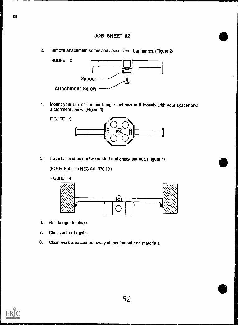
3. Remove attachment screw and spacer from bar hanger. (Figure 2)
FIGURE 2
Spacer
Attachment Screw
4. Mount your box on the bar hanger and secure it loosely with your spacer andattachment screw. (Figure 3)
FIGURE 3
5. Place bar and box between stud and check set out. (Figure 4)
(NOTE: Refer to NEC Art: 370-10.)
FIGURE 4
6. Nail hanger in place.
7. Check set out again.
8. Clean work area and put away all equipment and materials.
82

RW-67
ROUGH-INUNIT II
JOB SHEET #3 - WIRE A SWITCH CONTROLLED SPL1T-WIREDRECEPTACLE
A. Equipment and materials needed
1. 12-2G or 14-2-G NM cable
2. 12-3G or 14-3-G NM cable
3. Two device boxes
(NOTE: Be sure boxes have a NEC capacity rating to accommodate the conduc-tors you will install.)
4. Staples
5. Single pole switch
6. Duplex grounding type receptacle
7. Stud wall or work board
8. 120v supply
(NOTE: The overcurrent protection on this supply should not exceed the conduc-tors NEC ampacity rating.)
9. 3/8" cable clamp
10. Wire connectors
11. Four 16 penny nails or other fasteners as needed to secure the boxes
12. Electrician's hammer
13. Plain tip screwdriver
14. Lineman's pliers
15. Needle-nose pliers
16. Pocket knife
17. Wire strippers
18. Tool pouch

68
JOB SHEET #3
19. Drill motor or brace
20. 1/2" or larger wood bit
21. Extension cord
22. Safety glasses
23. GFI
S. Procedure
1. Put on safety glasses and gather equipment and materials.
2. Mount boxes. (Figure 1)
FIGURE 1
3. Remove a half inch knockout from the panel.
4. Install cable connector.
84

JOB SHEET #3
5. Bore holes for cable
(NOTE: Holes should be drilled as close to the center (front to back) of a stud aspossible. Holes should be drilled at least 6 inches above or below the boxdepending on which route is the closest.)
(CAUTION: Be sure and use a GFI when drilling.)
6. Run cable between boxes and to panel. (Figure 2)
FIGURE 2--"--......,
122Gor
142G
12-3Gor
14-3G
(NOTE: Leave at least 6" extending past the surface of your device boxes, andenough to reach the top of your panel plus half the width.)
7. Staple cable within 12" of metal boxes, 6" of all nonmetallic boxes.
8. Secure all cable clamps and connectors.
(CAUTION: Tighten them until the cable will not slip in the box; overtighteningcan cause an electrical short4
9. Strip cable insulation at device box and panel.
RW-69

70
JOB SHEET #3
10. Connect equipment grounding conductors. (Figure 3)
FIGURE 3
11. Make up switch box. (Figure 4)
FIGURE 4
R6

RW-71
JOB SHEET #3
12. Connect grounded and ungrounded conductors. (Figure 5)
FIGURE 5
Connect grounded conductor first
(NOTE Be sure the breaker is off or the fuse is out before connecting this con-ductor. Always be safety conscious.)
13. Have your instructor ev.- :ate this project.
14. Clean work area and put away all equipment and materials.
87

RW-73
ROUGH-INUNIT II
JOB SHEET #4 - WIRE A RECEPTACLE FED FROM A LIGHTINGOUTLET THROUGH A SINGLE POLE SWITCH
A. Equipment and materials needed
1. 12-2G or 14-2-G NM cable
2. 12-3G or 14-3-G NM cable
3. Two device boxes
4. Octagon box and bar hanger
5. Light socket
6. 120 volt bulb
7. Staples
8. Single pole switch
9. Duplex grounding type receptacle
10. Stud wall or work board
11. 120v supply
(NOTE: The ovircurrent protection on this supply should not exceed the conduc-tors NEC ampacity rating.)
s&. Wire connectors.,...
13. Four 16 penny nails or other fasteners as needed to secure the boxes
14. Electrician's hammer
15. Plain tip screwdriver
16. Lineman's pliers
17. Long nose pliers
18. Pocket knife
19. Wire strippers
88

74
JOB SHEET #4
20. Tool pouch
21. Drill motor or brace
22. 112" or larger wood bit
23. Extension cord
24. Safety glasses
25. GFI
B. Procedure
1. Put on safety glasses and gather equipment and materials.
2. Mount boxes. (Figure 1)
FIGURE 1 ---%,---____--s-------- "--,-...,..-----....,._.._._...,f1..-rs,.
S"---------..,_e--r---.........--
3. Remove a ha;f inch knockout from the panel.
4, install cable connector.
89

RW-75
JOB SHEET #4
5. Bore holes for cable.
(NOTE: Holes should be drilled as close to the center (front to back) of a stud aspossible. Holes shoold be drilled at least 6 inches above or below the boxdepending on which route is the closest.)
(CAUTION: Always use a GFI when drilling.)
6. Run cable between boxes and to panel. (Figure 2)
FIGURE 2
12 or 14-2Gfrom panelto light
12 or 14.3Gfrom lightto switch
12 or 14-2Gfrom switchto receptacle
%--_____,.._
(NOTE: Leave at least 3" extending past the surface of your device boxes, andenough to reach the top of your panel plus half the width.)
7. Staple cable within 12" of metal boxos, 6" of nonmetallic boxes.
8. Secure all cable clamps and connectors.
(CAUTION: Tighten them untii the cable will n' iip in the box; overtIghteningcan cause an electric$41 short.)
9. Strip cable insulation at device box and panel.
90

76
JOB SHEET #4
10. Connect equipment grounding conductors. (Figure 3)
FIGURE 3
11. Make up neutral through the system. (Figure 4)
FIGURE 4
.wariaiwoilmmam.
91

RW-77
JOB SHEET #4
12. Make up switch, return, and feed through conductors. (Figure 5)
FIGURE 5
13. Connect ungrounded conductors. (Figure 6)
FIGURE 6
(NOTE: Be sure the breaker is off or the fuse is out before connecting this con-ductor. Always be safety conscious.)
14. Have your instructor evaluate this project.
15. Clean work area and put away all equipment and materials.

RW-79
ROUGH-INUNIT II
JOB SHEET #5 WIRE A RECEPTACLE FED FROM A LIGHTINGOUTLET THROUGH A THREE-WAY SWITCH
A. Equipment and materials needed
1. 12-2G or 14-2-G NM cable
2. 12-3G or 14-3-G NM cable
3. Three device boxes
(NOTE: One of the device holding boxes will have to be a 4" square box with aplaster ring.)
4. Octagon box and bar hanger
(NOTE: Be sure boxes have a NEC capacity rating to accommodate the conduc-tors to be installed.)
5. Staples
6. Two 3-way switches
7. One duplex grounding type receptacle
8. Light socket
9. Bar hanger
(NOTE: if a bracket octagon box is used or if this job is installed on a work board,a bar hanger will not be needed.)
10. Stud wall or work board
11. 120v supply
(NOTE: The overcurrent protection on this supply should not exceed the conduc-tors NEC ampacity rating.)
12. 31a" cable clamp
13. 120v incandescent bulb
14. Wire connectors
(NOTE: Twist on connectors will be used in this manual for illustrations. Wireconnectors, pressure connectors or solder would also be acceptable in thetrade.)
93

80
JOB SHEET #5
15. Two 16 penny nails
16. Two plasterboard nails
17. Electrician's hammer
18. Plain tip screwdriver
19. Lineman's pliers
20. Long nose pliers
21. rocket knife
22. Wire strippers
23. Tool pouch
24. Drill motor or brace
25. 1/2" or larger wood bit
26. Extension cord
27. Safety glasses
28. GFI
B. Procedure
1. Put on safety glasses and gather equipment and materials.
2. Mount boxes. (Figure 1)
(NOTE: Device boxes and ceiling can be mounted at any height in this project.)
FIGURE 1
94

RW-81
JOB SHEET #5
3. Remove a half inch knockout from the panel.
4. Install cable connector.
5. Bore holes for cable.
(NOTE: Holes should be drilled as close to the center (front to back) of a stud aspossible. Holes should be drilled at least 6 inches above or below the boxdepending on which route is the closest.)
(CAUTION: Be sure and hold the drill securely. A loose grip can cause an acci-dent. Be sure and use a GFI when drilling.)
6. Run cable. (Figure 2)
FIGURE 2
12 or 14-2G
12 or 14.3G
*------ -......----^"..---""---,---------,
...-- ----
(NOTE: Leave at least 6" extending past the surface of your device ar, lightingoutlet boxes, and enough to reach the top of your panel plus half the width.)
7. Staple cable within 12" of metal boxes, 6" of nonmetallic boxes.
8. Secure all cable clamps and connectors.
(CAUTION: Tighten them until the cable will not slip in the box; overtighteningcan cause an electrical short.)
95

82
JOB SHEET #5
9. Strip cable insulation.
(CAUTION: Extreme care should always be used in operations involving the knife;a cut hand can cause pain and lost work time.)
10. Connect all grounding conductors. (Figure 3)
FIGURE 3
11. Connect all neutral conductors. (Figure 4)
FIGURE 4
96

RW-83
JOB SHEET #5
12. Connect switch leg through the system. (Figure 5)
13. Connect ungrounded conductor to appropriate overcurrent device. (Figure 6)
F',GURE 6
(CAUTION: Be sure the breaker is off or the fuse is out before connecting thisconductor. Always be safety conscious.)
14. Have your instructor evaluate this project.
15. Clean work area and put away all equipment and materials.
97

RW-85
ROUGH-INUNIT H
JOB SHEET #6 WIRE A FOUR WAY SWITCHING SITUATION WITHTHE SUPPLY ENTERING THE LIGHTING OUTLET BOX
A. Equipment and materials needed
1. 12-2-G or 14-2-G and12-3-G or 14-3-G NM cable
2. Three device boxes
3. Octagon box
(NOTE: Be sure your boxes have a NEC capacity rating to accommodate the con-ductors you will install.)
4. Staples
5. Two 3 way switches
6. One 4 way switch
7. Light socket
8. Bar hanger
(NOTE: If a bracket octagon box is used or if this job is installed on a work board,a bar hanger will not be needed.)
9. Stud wall or work board
10. 120v supply
(NOTE: The overcurrent protection on this supply should not exceed the conduc-tor's NEC ampacity rating.)
11. 3/8 cable clamp
12. 120v incandescent bulb
13. Wire connectors
(NOTE: Twist on connectors will be used in this manual for illustrations. Wireconnectors, pressure connectors, or solder would also be acceptable in thetrade.)
14. Two 16 penny nails
15. Two plasterboard nails

JOB SHEET #6
16. Electrician's hammer
17. Plain tip screwdriver
18. Lineman's pliers
19. Long nose pliers
20. Pocket knife
21. Wire stripper.;
22. Tool pouch
23. Drill motor or brace
24. 112" or larger wood bit
(NOTE Holes should be large enough to safely accommodate the cables.)
25. Extension cord
26. Safety glasses
27. Portable GF1
B. Procedure
1. Put on safety glasses and gather equipment and materials.
2. Mount boxes. (Figure 1)
(NOTE Switch box and ceiling outlet can be mounted at any height in this pro-ject.)
FIGURE 1
99
e

RW-87
JOB SHEET #6
3. Remove a half inch knockout from the panel.
4. Install cable connector.
5. Plug cord into GFI.
6. Bore holes for cable.
(NOTE: Holes should be drilled as close to the center (front to back) of a stud aspossible. Holes should be drilled at least 6 inches above or below the boxdepending on which route is the closest.)
(CAUTION: Be sure and hold the drill securely. A loose grip can cause an acci-dent.)
7. Run cable. (Figure 2)
FIGURE 2
12 or 14-2G
12 or 14-3G
IT12 or 1 4-2G
12 or 1 4-3G
(NOTE Leave at least 6" extending past the surface of your device and lightingoutlet boxes, and enough to reach the top of your pane; plus half the width.)
8. Staple cable within 12" of metal boxes, 6" of nonmetallic boxes.
9. Secure all cable clamps and connectors.
(CAUTION: Tighten them until the cable will not slip in the box; overtighteningcan cause an electrical short.)

JOB SHEET #6
10. Strip cable insulation.
(NOTE: Trim the cable covering to within 1/4" of its point of entry.)
(CAUTION: Extreme care should always be used in operations involving a knife; acut hand can cause pain and lost work time.)
11. Connect all grounding conductors. (Figure 3)
FIGURE 3
(NOTE: Always leave enough conductor to make removal and reconnection easy.Notice extra bend at panel.)
12. Connect neutral conductors. (Figure 4)
FIGURE 4
101

RW-89
JOB SHEET #6
13. Connect switch leg through the system. (Figure 5)
FIGURE 5
14. Install switches. (Figure 6)
FIGURE 6
102

90
JOB SHEET #6
15. Connect return leg to socket. (Figure 6)
16. Connect ungrounded conductor to appropriate overcurrent device. (Figure 7)
FIGURE 7
(CAUTION: Be sure the breaker is off or the fuse is out before connecting thisconductor. Always be safety conscious.)
17. Turn on breaker.
(CAUTION: Stand to the side of the panel when turning on the breaker. A short inthe circuit could cause molten metal to fly from the panel)
18. Change the position of the switches in alternating movements.
(NOTE: Be sure you can turn on or off from either switch as well as on at one andoff at the other.)
19. Have your instructor evaluate this project.
20. Turn off breaker.
21. Clean work area and put away all equipment and materials.
4
J 03
Itataitmer-aasmsor

RW-91
ROUGHINUNIT II
JOB SHEET #1 PRACTICAL TEST - INSTALL A DEVICE BOXWHEN GIVEN CABINET HEIGHT AND WALL COVERING
STUDENT'S NAME DATE
EVALUATOR'S NAME ATTEMPT NO
Instructions: When you are ready to perform this task, ask your instructor to observe the pro-cedure and complete this form. All items listed under "Process E' luation" must receive a"Yes" for you to receive an overall performance evaluation.
PROCESS EVALUATION
(EVALUATOR NOTE: Place a check mark in the "Yes" or "No" blanks to designate whether ornot the student has satisfactorily achieved each step in this procedure. If the student isunable to achieve this competency, have the student review the materials and try again.)
The student: YES NO
1. Checked out proper tools and materials.2. Marked correct height for box.3. Set box on stud.4. Nailed box to stud.5. Checked in/put away tools and materials.6. Cleaned the work area.7. Used proper tools correctly.8. Performed steps in a timely manner ( hrs _min _sec.)9. Practiced safety rules throughout procedure.
10. Provided satisfactory responses to questions asked.
EVALUATOR'S COMMENTS:

92
JOB SHEET #1 PRACTICAL TEST
PRODUCT EVALUATION
(EVALUATOR NOTE: Rate the student on the following criteria by circling the appropriate num-bers. Each item must be rated at least a "3" for mastery to be demonstrated. (See performanceevaluation key below.) If the student is unable to demonstrate mastery, student materialsshould be reviewed and another product must be submitted for evaluation.)
Criteria:
4 3 2 1
Measurements correct
4 3 2 1
Box is set for Sheetrock
4 3 2 1
Box mounted properly
4 3 2 1
Workmanship
4 3 2 1
Compliance to NEC
EVALUATOR'S COMMENTS:
PERFORMANCE EVALUATION KEY
4 Skilled Can perform Job with no additional training.3 Moderately skilled Has performed job during training program; limited
additional training may be required.2 Limited skill Has performed job during training program; additional
training is required to develop skill.1 Unskilled Is familiar with process, but is unable to perform job.
(EVALUATOR NOTE: If an average score is needed to coincide with a competency profile, totalthe designated points in "Product Evaluation" and divide by the total number of criteria.)
105

RW-93
ROUGH-INUNIT Ii
JOB SHEET #2 PRACTICAL TEST INSTALL A LIGHTINGOUTLET BOX WHEN GIVEN CEILING COVERING THICKNESS
STUDENT'S NAME DATE
EVALUATOR'S NAME ATTEMPT NO
Instructions: When you are ready to perform this task, ask your instructor to observe the pro-cedure and complete this form. All items listed under "Process Evaluation" must receive a"Yes" for you to receive an overall performance evaluation.
PROCESS EVALUATION
(EVALUATOR NOTE: Place a check mark in the "Yes" or "No" blanks to designate whether ornot the student has satisfactorily achieved each step in this procedure. If the student isunable to achieve this competency, have the student review the materials and try again.)
The student: YES NO
1. Checked out proper tools and materials.2. Removed center K.O..3. Installed bar hanger to box.4. Attached bar hanger and box to wall.5. Checked in/put away tools and materials.6. Cleaned the , Irk area.7. Used proper tools correctly.8. Performed steps in a timely manner (_hrs _min. _sec.)9. Practiced safety rules throughout procedure.
10. Provided satisfactory responses to questions asked.
EVALUATOR'S COMMENTS:
106

94
JOB SHEET #2 PRACTICAL TEST
PRODUCT EVALUATION
(EVALUATOR NOTE: Rate the student on the following criteria by circling the appropriate num-bers. Each item must be rated at least a "3" for mastery to be demonstrated. (See performanceevaluation key below.) If the student is unable to demonstrate mastery, student materialsshould be reviewed and another product must be submitted for evaluation.)
Criteria:
4 3 2 1
Bar hanger mounted cor-rectly
4 3 2 1
Box and hanger mountedproperly
4 3 2 1
Box set for Sheetrock
4 3 2 1
Workmanship
4 3 2 1
Compliance to NEC
EVALUATOR'S COMMENTS:
PERFORMANCE EVALUATION KEY
4 Skilled Can perform job with no additional training.3 Moderately skilled Has performed job during training program; limited
additional training may be required.2 Limited skill Has performed job during training program; additional
training is required to develop skill.1 Unskilled is familiar with process, but is unable to perform job.
(EVALUATOR NOTE: if an average score is needed to coincide with a competency profile, totalthe designated points in "Product Evaluation" and divide by the total number of criteria.)
107

RW-95
ROUGHINUNIT II
JOB SHEET #3 PRACTICAL TEST - WIRE A SWITCH CONTROLLEDSPLIT-WIRED RECEPTACLE
STUDENT'S NAME DATE
EVALUATOR'S NAME Ai TEMPT NO
Instructions: When you are ready to perform this task, ask your instructor to observe the pro-cedure and complete this form. All items listed under "Process Evaluation" must receive a"Yes" for you to receive an overall performance evaluation.
PROCESS EVALUATION
(EVALUATOR NOTE: Place a check mark in the "Yes" or "No" blanks to designate whether ornot the student has satisfactorily achieved each step in this procedure. If the student isunable to achieve this competency, have the student review the materials and try again.)
The student: YES NO
1. Checked out proper tools and materials.2. Mounted boxes to studs.3. Removed K.O. from panel.4. Installed 1/2 inch connector.5. Bored hole In studs.6. Installed Romex.7. Stapled Romex to studs.8. Secured cable and clamps.9. Stripped Romex.
10. Grounded equipment.11. Made up connections.12. Checked in/put away tools and materials.13. Cleaned the work area.14. Used proper tools correctly.15. Performed steps in a timely manner (____hrs. _min _sec.)16. Practiced safety rules throughout procedure.17. Provided satisfactory responses to questions asked.
EVALUATOR'S COMMENTS:
1 08

96
JOB SHEET #3 PRACTICAL TEST
PRODUCT EVALUATION
(EVALUATOR NOTE: Rate the student on the following criteria by circling the appropriate num-bers. Each item must be rated at least a "3" for mastery to be demonstrated. (See performanceevaluation key below.) If the student is unable to demonstrate mastery, student materialsshould be reviewed and another product must be submitted for evaluation.)
Criteria:
Boxes mounted correctly4 3 2 1
Romex run properly4 3 2 1
Holes drilled correctly4 3 2 1
Romex stapled4 3 2 1
Make-ups correct4 3 2 1
Grounding correct4 3 2 1
Workmanship4 3 2 1
Compliance to NEC4 3 2 1
EVALUATOR'S COMMENTS:
PERFORMANCE EVALUATION KEY
4 Skilled Can perform job with no additional training.3 Moderately skilled Has performed job during training program; limited
additional training may be required.2 Limited skill Has performed job during training program; additional
training is required to develop skill.1 Unskilled Is familiar with process, but is unable to perform job.
(EVALUATOR NOTE: If an average score is needed to coincide with a competency profile, totalthe designated points in "Product Evaluation" and divids by the total number of criteria.)
1n9

ROUGH-INUNIT II
JOB SHEET #4 PRACTICAL TEST - WIRE A RECEPTACLEFED FROM A LIGHTING OUTLET THROUGH A SINGLE POLE SWITCH
STUDENT'S NAME DATE
EVALUATOR'S NAME ATTEMPT NO.
Instructions: When you are ready to perform this task, ask your instructor to observe the pro-cedure and complete this form. All items listed under "Process Evaluation" must receive a"Yes" for you to receive an overall performance evaluation.
PROCESS EVALUATION
(EVALUATOR NOTE Place a check mark in the "Yes" of "No" blanks to designate whether ornot the student has satisfactorily achieved each step in this procedure. If the student isunable to achieve this competency, have the student review the materials and try again.)
The student: YES NO
1. Checked out proper tools and materials.2. Mounted boxes on studs.3. Removed 112 K.O. from panel.4. Installed connector.5. Bored holes in studs.6. Installed Romex.7. Stapled Romex to studs.8. Stripped Romex in boxes.9. Connected grounding conductors.
10. Made up conductors.11. Checked inlput away tools and materials.12. Cleaned the work area.13. Used proper tools correctly.14. Performed steps in a timely manner ( hrs. __min. _sec.)15. Practiced safety rules throughout procedure.16. Provided satisfactory responses to questions asked.
EVALUATOR'S COMMENTS:
1 10
RW-97

98
JOB SHEET #4 PRACTICAL TEST
PRODUCT EVALUATION
(EVALUATOR NOTE: Rate the student on the following criteria by circling the appropriatenum-bers. Each item must be rated at least a "3" for mastery to be demonstrated. (See performanceevaluation key below.) If the student is unable to demonstrate mastery, student materialsshould be reviewed and another product must be submitted for evaluation.)
Criteria:
4Boxes mounted properly
4Holes bored correctly
3 2 1
3 2 1
4 3 2 1Romex run properly
4 3 2 1Romex stapled
4 3 2 1Make-up correct
4 3 2 1Grounded properly
4 3 2 1Workmanship
4 3 2 1Compliance to NEC
EVALUATOR'S COMMENTS:
PERFORMANCE EVALUATION KEY
4 Skilled Can perform job with no additional training.3 Moderately skilled Has performed job during training program; limited
additional training may be required.2 Limited skill Has performed job during training program; additional
training is required to develop skill.1 Unskilled Is familiar with process, but is unable to perform job.
(EVALUATOR NOTE: If an average score is needed to coincide with a competency profile, totalthe designated points in "Product Evaluation" and divide by the total number of criteria.)
11.E

ROUGH-INUNIT II
JOB SHEET #5 PRACTICAL TEST - WIRE A RECEPTACLEFED FROM A LIGHTING OUTLET THROUGH A THREEWAY SWITCH
STUDENT'S NAME DATE
EVALUATOR'S NAME ATTEMPT NO
Instructions: When you are ready to perform this task, ask your instructor to observe the pro-cedure and complete this form. All items listed under "Process Evaluation" must receive a"Yes" for you to receive an overall performance evaluation.
PROCESS EVALUATION
(EVALUATOR NOTE: Place a check mark in the "Yes" or "No" blanks to designate whether ornot the student has satisfactorily achieved each step in this procedure. If the student isunable to achieve this competency, have the student review the materials and try again.)
The student: YES NO
1. Checked out proper tools and materials.2. Mounted boxes to studs.3. Removed K.O. in panel and installed connector.5. Bored holes.7. Stapled Romex to studs.8. Stripped Romex in boxes.9. Connected grounding conductors.
10. Made up bores.11. Checked inlput away tools and materials.12. Cleaned the work area.13. Used proper tools correctly.14. Performed steps in a timely manner ( hrs. _min. _sec.)15. Practiced safety rules throughout procedure.16. Provided satisfactory responses to questions asked.
EVALUATOR'S COMMENTS:
RW-99

JOB SHEET #5 PRACTICAL TEST
PRODUCT EVALUATION
(EVALUATOR NOTE Rate the student on the following criteria by circling the appropriate num-bers. Each item must be rated at least a "3" for mastery to be demonstrated. (See performanceevaluation key below.) If the student is unable to demonstrate mastery, student materialsshould be reviewed and another product must be submitted for evaluation.)
Criteria:
4 3 2 1Boxes mounted correctly
4 3 2 1Holes drilled properly
4 3 2 1Romer_ run correctly
4 3 2 1Grounding connected
4 3 2 1Make-up correct
4 3 2 1Workmanship
4 3 2 1Compliance to NEC
EVALUATOR'S COMMENTS:
PERFORMANCE EVALUATION KEY
4 Skilled Can perform job with no additional training.3 Moderately skilled Has performed job during training program; limited
additional training may be required.2 Limited skill Has performed job during training program; additional
training is required to develop skill.1 Unskilled Is familiar with process, but is unable to perform job.
(EVALUATOR NOTE: If an average score is needed to coincide with a competency profile, totalthe designated points in "Product Evaluation" and divide by the total number of criteria.)
113

ROUGH-INUNIT II
RW-101
JOB SHEET #6 PRACTICAL TEST - WIRE A FOUR WAY SWITCHINGSITUATION WITH THE SUPPLY ENTERING THE LIGHTING OUTLET BOX
STUDENT'S NAME DATE
EVALUATOR'S NAME ATTEMPT NO
Instructions: When you are ready to perform this task, ask your instructor to observe the pro-cedure and complete this form. All items listed under "Process Evaluation" must receive a"Yes" for you to receive an overall performance evaluation.
PROCESS EVALUATION
(EVALUATOR NOTE: Place a check mark in the "Yes" or "No" blanks to designate whether ornot the student has satisfactorily achieved each step in this procedure. If the student isunable to achieve this competency, have the student review the materials and try again.)
The student:
1. Checked out proper tools and mater,nis.2. Box set out correct for wall covering thichness.3. Bar hanger mounted securely.4. Box mounted securely to bar hanger.5. Cable stripped without nicking conductor insulation.6. Conductor insulation stripped without nicking conducior.7. Conductors neatly folded inside switch boxes.8. Proper connection of conductors made at 4 way switch.9. Proper connection of conductors made at 3 way switches.
10. Proper connection of conductors made at lighting outlet.11. Proper connection of conductors made at panel.12. Checked in/put away tools and materials.13. Cleaned the work area.14. Used proper tools correctly.15. Performed steps in a timely manner ( hrs. _min. _sec.)16. Practiced safety rules throughout procedure.17. Provided satisfactory responses to questions asked.
YES NO
EVALUATOR'S COMMENTS:
1 14

102
JOB SHEET #6 PRACTICAL TEST
PRODUCT EVALUATION
(EVALUATOR NOTE: Rate the student on the following criteriaby circling the appropriate num-bers. Each item must be rated at least a "3" for mastery to be demonstrated. (See performanceevaluation key below.) If the student is unable to demonstrate mastery, student materialsshould be reviewed and another product must be submitted for evaluation.)
Criteria:
4 3 2 1
Devices installedsecurely
4 3 2 1
Light is controlled from 3way switches on/off
4 3 2 1
Light is controlled from 4way switch
4 3 2 1
Workmanship
4 3 2 1
Compliance to NEC
EVALUATOR'S COMMENTS:
PERFORMANCE EVALUATION KEY
4 Skilled Can perform job with no additional training.3 Moderately skilled Has performed job during training program; limited
additional training may be required.2 Limited skill Has performed job during training program; additional
training is required to develop skill.1 Unskilled Is familiar with process, but is unable to perform job.
(EVALUATOR NOTE: If an average score is needed to coincide with a competency profile, totalthe designated points in "Product Evaluation" and divide by the total number of criteria.)
1 1 5

ROUGH-INUNIT II
TEST
NAME SCORE
1. Match the terms on the right with their correct definitions.
a Midpoint on a box's vertical dimension 1. Backsplash
b Point in a room that is equal distance from 2. Box centerparallel walls
3. Box set outc That portion of a wall inhind the kitchen
cabinet, starting at the countertop and end- 4. Flushing at the bottc;n of the wall hung cabinets
5. Habitabled Final tile in a ceramic backsplash when the
tile is terminated at some point up the wall 6. Room center
e Distance that the box exiends past the stud 7. Tile cap
f Suitable for people to occupy or live in
g Even with the surface
2. List five locations where at least one receptacle outlet is required.
a.
b.
c.
d.
e.
3. Select true statements concerning planning techniques when placing boxes on plansby placing an "X" in the blanks preceding the true statements.
a Keep spacing even where possible.
b Put boxes in uneven groups if possible.
c Check door swing direction so switches are behind doors.
d Place outside lighting outlets low enough for any fixture.
RW103

104
TEST
4. Complete the following accepted heights for boxes in various locations by circling thenumbers which best complete each statement.
a. Above kitchen counter tops (40", 45") to box center
b. Above bathroom cabinets (44", 401 to box center
c. Receptacles along floor line (12", 10") to box centers
d. Wall switches (46", 52' to box centers
5. Select true statements concerning the procedure for installing boxes in exterior wallsto be brick veneered by placing an "X" in the blanks preceding the correct statements.
a Punch a large hole in wall sheeting.
b Push cable through newly formed hole.
c. Put the cable through the back knockout of your box and secure with acable clamp.
d Put screws in the device securing holes.
6. Distinguish between box extensions for noncombustible and combustible wall sw-faces by placing an "X" next to the location for combustible materials.
a. Not more than 1/4" recess from surface
b Flush with or projecting from surface
7. List two common methods of finding room centers.
a.
b.
8. Select true statements concerning required outlets by placing an "X" in the blanks pre-ceding the true statements.
a. In every kitchen, family room, dining room, living room, or similar rooms ofdwelling units, receptacle outlets shall be installed so that no point alongthe floor line in any wall space is more than 8 feet measured horizontally,from an outlet in that space, including any wall space 2 feet or more Inwidth and the space occupied by sliding panels in exterior doors. The wallspace afforded by fixed room dividers such as free standing bar typecounters, shall be included in the measurement.
13. In kitchen and dining areas of dwelling units a receptacle outlet shall beinstalled at each counter space wider than 12 inches.
1 1 7

TEST
c At least one receptacle outiet shall be installed in a bathroom adjacent tothe commode location.
d. At least one receptacle outlet shall be installed outdoors.
e. At least two receptacle outlets shall be installed in laundry areas.
f A* least one wall switch controlling a lighting outlet is required in everyrcom including the hallway, bathroom, stairway, attached
garage, outdoor entrance, and in attics, under floor space, utility rooms,and basements if used for storage or if containing equipment requiringservice.
9. Complete the following statements concerning rules for electrical installations byinserting the word(s) which best complet.5 each statement.
a. be safety conscious.
b. Be sure all connections are secure and
c. Always be sure that overcurrent protection is matched to your conductor
d. conductors before installing devices in boxes.
e. Use appropriate
f. Always meet or exceedinstallation requirements.
(NOTE: If the following activities have not been accomplished prior to the test, ask yourinstructor when they should be completed.)
10. Locate receptacle, switch, and lighting outlets along a floor line and the ceiling on ablueprint. (Assignment Sheet #1)
11. Locate receptacle outlets along kitchen cabinets. (Assignment Sheet #2)
12. Demonstrate the ability to:
a. Install a device box when given cabinet height and wall covering. (Job Sheet #1)
b. Install a lighting outlet box when given ceiling covering thickness. (Job Sheet #2)
c. Wire a switch controlled split-wired receptats:le. (Job Sheat #3)
d. Wire a receptacle fed from a lighting outlet through a single pole switch. (JobSheet #4)
e. Wire a receptacle fed from a lighting outlet through a three-way switch. (JobSheet #5)
f. Wire a four way switching situation with the supply entering the lighting outletbox. (Job Sheet #6)
, state, and local code minimum
4 1 8

RW-107
ROUGH-INUNIT II
ANSWERS TO TEST
1. a. 2 e. 3b. 6 f. 5c. 1 g. 4d. 7
2. a. Bathroom Adjacent to sinkb. Laundry Within ',ix feet of appliance to be servedc. Outsided. Basemente. Attached garage
3. a, d
4. a. 45"b. 40"c. i2"d. 48"
5. b, c, d
6. b
7. a. Corner to corner chalkline and plumb bob transferb. Measuring half wall lengths, out at right angles from the walls
8. b, d, f
9. a. Alwaysb. Well insulatedc. Ratingd. Preforme. Toolsf. NEC
10.-11. Evaluated to the satisfaction of the instructor
12. Performance skills evaluated to the satisfaction of the instructor
1 1 9

RW-109
SERVICEUNIT III
UNIT OBJECTIVE
After completion of this unit, the student should be able to properly design, size, and install aresidential service. Competencies will be demonstrated by completing the assignment sheet,job sheets, and the unit tests with a minimum score of 85 percent.
SPECIFIC OBJECTIVES
After completion of this unit, the student should be able to:
1. Match terms related to service with their correct definitions.
2. Match required clearances for service drop conductors with their locations.
3. Select true statements concerning service disconnects.
4. List four facts that should be known before the service installation is started.
. Identify the parts of a service entrance.
6. Select types of grounding electrodes.
7. Complete statements concerning grounding electrode conductor installationsand sizes.
8. Select true statements concerning short circuit protection at service equipment.
9. Select true statements concerning surge protection.
10. Calculate service size and minimum number of circuits. (Assignment Sheet #1)
120

110
OBJECTIVE SHEET
11. Demonstrate the ability to:
a. Install an overhead raceway with service entrance conductors to a meterbase. (Job Sheet #1)
b. Connect meter base assembly to load center or panel. (Job Sheet #2)
c. Install an underground service (lateral) raceway with conductors to a meterbase. (Job Sheet #3)
121

SERVICEUNIT III
SUGGESTED ACTIVITIES
A. Obtain additional materials and/or invite resource people to class to supplement/rein-force information provided in this unit of instruction.
(NOTE: This activity should be completed prior to the teaching of this unit.)
B. Make transparencies from the transparency masters included with this unit.
C. Provide students with objective sheet.
D. Discuss unit and specific objectives.
E. Provide students with information and assignment sheet.
F. Discuss information and assignment sheet.
(NOTE: Use the transparencies to enhance the information as needed.)
G. Provide students with job sheets.
H. Discuss and demonstrate the procedures outlined in the job sheets.
I. Integrate the following activities throughout the teaching of this unit:
1. Have students review Unit X: Overcurrent Protection in Bask Wiring.
2. Contact a local sales distributor to discuss and demonstrate fuses and circuitbreaker types.
3. Contact a local electrical utility representative to discuss local requirements forservices and meter demonstration.
4. Contact local code enforcement (inspection) department to schedule visit ofInspection to inform class about local regulations and requirements for serviceinstallation and grounding.
5. If possible, plan an on-sight visit to a residence under construction to see rough-inof service installationunderground or overhead or both.
6. Meet individually with students to evaluate their progress through this unit ofinstruction, and indicate to them possible areas of improvement.
J. Give test.
K. Evaluate test.
L Reteach if necessary.
1 22
RW-111

112
REFERENCES USED IN WRITING THIS UNIT
A. Buss Fuses Full Line Condensed Catalog, January 1985. St. Louis, MO: BussmanDivision, McGraw Edison Company.
(NOTE: For a copy of this catalog, write to P.O. Box 14460, St. Louis, MO 63178.)
B. D Digest 1987. Palatine, IL: Square D Company.
C. Earl, John T. Electrical Wiring Design and Application. Englewood Cliffs, NJ: PrenticeHall, 1983.
D. Foley, Joseph H. Electrical Wiring Fundamentals. New York: Gregg, McGraw-Hill BookCompany, 1981.
E. Gray, Elliott C.; R. Bailey; and E. Melbourne. Electrical Construction and MaintenanceTechniques. Englewood Cliffs, NJ: Prentice Hall, 1986.
F. National Electrical Code, 1987. Quincy, MA: National Fire Protection Association, 1986.
G. Pass and Seymore Wiring Devices Catalog #486. Syracuse, NY.
(NOTE: For a copy of this catalog, write to P.O. Box 4822, Syracuse, NY 13221.)
H. Richter, Herbert R and W. Creighton Schwan. Practical Electrical Wiring. Thirteenth Edi-tion. Englewood Cliffs, NJ: Prentice Hall, 1984.
I. Stallcup, James G. Designing Electrical Systems. Homewood, IL: American TechnicalPublishers, Inc., 1985.
J. Taylor, Mark. Residential Wiring. Revised. Stillwater, OK: Mid-America Vocational Curric-ulum Consortium, 1983.
SUGGESTED SUPPLEMENTAL MATERIAL
Filmstrips
A. Electrical Wiring. Unit IV, Installing Service Equipment. American Association for Voca-tional Instructional Materials, 120 Engineering Center, Athens, GA 30602.
B. Electrical House Wiring Explained #803 #6 Fuse and Circuit Breaker Panels.Bergwall Productions, Inc., 839 Stewart Ave., Garden City, NY 11530.
C. Residential Electrical Wiring Explained #804 804A.3, Underground Service Entrance.Bergwall Productions, Inc., 839 Stewart Ave., Garden City, NY 11530.
D. Electrical Wiring, Unit 1, Number 3, Fuses, Circuit Breakers and GFCIt, Unit I, Number2, Grounding. DCA Educational Products, 424 Valley Rd., Warrington, PA 18976.
E. Wiring A House Unit 3, Number 1, Overheat Service and Unit 3, Number 2, Installingthe Panel. DCA Educational Products, 424 Valley Rd., Warrington, PA 18976.
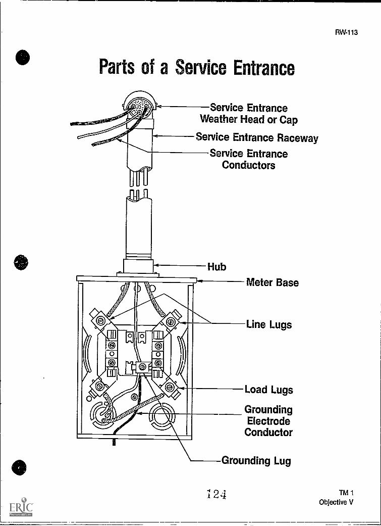
Parts of a Service Entrance
Service EntranceWeather Head or Cap
Service Entrance Raceway
Service EntranceConductors
Meter Base
Line Lugs
Load Lugs
GroundingElectrode
Conductor
Grounding Lug
-I 9 1I L., .4
RW-113
TM 1
Objective V

Parts of a Service Entrance(Continued)
Service EntranceConductors
Service Lateral
UndergroundService Raceway
125
RW-115
TM 2
Objective V

Parts of a Service Entrance(Continued)
Service Mast
Load Center
. . ..-%::::::a:5:
RW-117
Roof Flashing
ServiceEntranceRaceway
Meter
Meter Base
NOTE: Grounding can
be done through meterbase or through panel.
126
TM 3
Objective V

Installing Grounding Rod
Ground rod must be8 feet in length.
a , a
I , I 5
*0 I
127
TM 4
Objective VI

RW-121
SERVICEUNIT III
INFORMATION SHEET
I. Terms and definitions
A. Circuit breaker Automatic overcurrent device that trips on overloads orshorts and is resettable
B. Cutout box An enclosure designed for surface mounting and havingswinging doors or covers secured directly to and telescoping with the wallsof the box proper
C. Disconnecting means A device or group of devices, or other means bywhich the conductors of a circuit can be disconnected from their source ofsupply
D. Grounding electrode conductor Conductor used to connect the ground-ing electrode to the equipment grounding conductor andlor the groundedconductor of the circuit at the service
E. Overcurrent protection Weak link in the circuit that limits the amperageto a specified amount
F. Roof flashing Protective equipment used where the mast emerges fromthe roof or eave to seal around the raceway and protect against water dam-age
(NOTE: The majority of the following definitions are from NEC Article 100.)
G. Service Where power is metered or is first attached to the structure
H. Service cable Service conductors made up in the form of a cable
I. Service conductors Supply conductors that extend from the street mainor from transformers to the service equipment of the premises to be sup-plied
J. Service drop Power conductors coming into building from power company
K. Service entrance conductors, underground system Service conductorsbetween the terminals of the service equipment and the point of connec-tion to the service lateral
L. Service entrance conductors, overhead system Service conductorsbetween the terminals of the service equipment and a point usually outsidethe building, clear of building walls, where joined by tap or splice to theservice drop
128

122
INFORMATION SHEET
M. Service equipment Necessary equipment, usually consisting of a circuitbreaker or fuses and their accessories, located near the point of entrance ofsupply conductors to a building or other structure, or an otherwise definedarea, and intended to constitute the main control and means of cutoff of thesupply
(NOTE: Overcurrent devices shall not be located in the vicinity of easilyignitable material such as in clothes closets.)
N. Service lateral Underground service conductors between the streetmain, including any risers at a pole or other structure or from transformersand the first point of connection to the service entrance conductors in a ter-minal box or meter or other enclosure with adequate space inside or out-side the building wall
(NOTE: Where there is no terminal box, meter, or other enclosure with ade-quate space, the point of connection shall be considered to the point ofentrance of the service conductors into the building.)
0. Service mast That portion of a service raceway that extends through aroof or eave
P. Service raceway Raceway that encloses the service entrance conduc-tors
Q. Short circuit Unintentional contact of a conductor
II. Clearances for service drop conductors not in excess of 600v
(NOTE: NEC Art: 230 deals with services.)
A. Over roofs Not less than 8' from highest point except where the voltagebetween conductors does not exceed 600 and:
1. If the roof has a slope of not less than 4" in 12", a 3' minimum is per-mitted on systems which do not exceed 300v between conductors
2. If the conductors do not pass over more than 4' of overhang and areterminated at a through-the-roof raceway or support, an 18" mini-mum is permitted on systems which do not exceed 300v betweenconductors.
B. From ground vertically
1. 10 feet At the electric service entrance to buildings, or at the driploop of the building electric entrance, measured from final grade orother accessible surface only for servicedrop cables supported onand cabled together with a grounded bare messenger and limited to150 volts to ground
129

RW-123
INFORMATION SHEET
2. 12 feet For those areas listed in the 15 foot classification when thevoltage is limited to 300 volts to ground
3. 15 feet Over residential property and driveways, and those com-mercial areas are not subject to truck traffic
4. 18 feet Over public streets, alleys, roads, parking areas subject totruck traffic, driveways on other than residential property, and otherland traversed by vehicles such as cultivated, grazing, forest, andorchard
III. Service disconnects
A. Maximum number of service entrance disconnects Not more than sixswitches or circuit breakers in single enclosure or grouped on a switch-board
(NOTE: NEC Art: 230 deals with services. Where a residence requires morethan six circuits, a main breaker is generally used.)
B. Transfer switches A double throw switch is used to transfer the alternatesource of supply in case main service is lost. The transfer switch must dis-connect the main service before connecting the alternate source. Thisswitch may be manually or automatically operated.
(NOTE: NEC Art: 230-83 deals with transfer switches.)
IV. Facts that should be known before the service installation is started
A. Whether underground or overhead service will be used
B. Voltage and amperage of service needed
C. Point at which service conductors are to enter the building
D. Size of service equipment needed
130

124
INFORMATION SHEET
V. Parts of a service entrance
Service EntranceWeather Head or Cap
Service Entrance Raceway
Service EntranceConductors
Service Mast
Load Center
Meter Base
Line Lugs
Load Lugs
GroundingElectrodeConductor
-Grounding Lug
Service EntranceConductors
Service Lateral
UndergroundService Raceway
Roof Flashing
ServiceEntranceRaceway
Meter
Meter Base
NOTE
/Grounding can be donethrough meter base orthrough panel
; :31

RW-125
INFORMATION SHEET
VI. Types of grounding electrodes
(NOTE: NEC Art: 250 deals with grounding.)
A. Structural metal Nearest available effectivRiy grounded structural metalmember of the structure
B. Water pipe Metal water pipe shall be used when available
(NOTE: It should be in direct contact with earth for 10 feet or more and elec-trically continuous to the points of connection of the grounding electrodeconductor and the bonding conductors.)
C. Made electrodes
1. At least 20' of bare copper conductor not smaller than No. 4 AWG orone or more steel reinforced bars or rods of not less than 1/2" diame-ter encased in at least 2" of concrete in a foundation or footing
2. 8' lengths of:
a. 3/4" galvanized pipe
b. 5/8" iron or steel rod
c. 1/2" nonferrous rod (copper, brass, and other noncorrosivemetals)
I ,i, , i
0 ,L, Grounding rod must be' 1 8 feet in length.
e 'I I '
111111 i
i I I
(NOTE: Where a rock bottom is not encountered the electrodeshall be driven to a length of 8'. Where rock is hit at less than 4'the electrode shall be buried in a trench. A metal undergroundwater pipe shall be supplemented by an additional electrodeas specified in NEC Articles 250-81 or 250-3)
3. At least 20' of #2 bare copper 21/2' undergrade encircling the struc-ture
L 2 2

126
INFORMATION SHEET
VII. Grounding electrode conducl. : installations and sizes
(NOTE: NEC Article 250 deals with grounding.)
A. Conductors and enclosures shall be secured to the surface they follow
B. #6 or larger conductors
1. Must be in conduit if suLlect ti, physical damage
2. If free from physical damage it may follow the surface of building ifstapled securely.
3. Aluminum or copper clad aluminum cannot be used in contact withmasonry or earth.
(NOTE: Grounding electrode conductor sizes are determined by referring toNEC Table 250-94.)
VIII. Short circuit protection at service equipment
A. Service equipment must be able to withstand the fault-current that thepower company's transformer could deliver in case of a short-circuit condi-tion.
B. Overcurrent protection devices must be selected to interrupt instantaneousshortcircuit currents (fault currents).
(NOTE: The following table represents the "Rule of Thumb" method for find-ing IC (interrupting capacity) ratings for fuses or circuit breakers.)
Ampacity of Service Service Rating IC Rating120/240V 1 Ph Less than 200A 10,000 A120/240V 1 Ph Less than 600A 42,000 A120/240V 3 Ph Less than 2000A 42,000 A
C. Formulas for short circuit calculations include:
1. Single phase, I KVA x 1000E
2. Three phase, I = KVA x 1000E x 1.73
I 3 3

RW-127
INFORMATION SHEET
IX. Surge protection
A. Voltage surges with peaks of several thousand volts, even on 120V circuits,are not uncommon. These surges occur because of induced voltages inpower lines resulting from lightning strikes in the vicinity of the line. Surgearresters for installation as part of an electric service and for use with cord-and-plug-connected electronic equipment are commercially available.
B. Lig ining surge arresters must fulfill the following functions:
1. They must not allow the passage of current to ground as long as thevoltage is normal,
2. When the voltage rises to a definite amount above normal, they mustprovide a path to ground for discharge of surge energy.
3. As soon as the voltage has returned below the setting of the arresterthe arrester must stop the flow of current to ground and re-insulateitself so as to insulate the supply conductor from ground.
4. Arresters must not be damaged by the discharge and be capable ofautomatically repeating their action as frequently as is required.
e.) .1

128
INFORMATION SHEET
X. Sizing the service entrance conductors
(NOTE: In Unit I, Blueprint Reading and Load Calculations, we learned the proce-dure for various circuit calculations. It is now necessary to carry those calcula-tions one step further to determine the size of service entrance conductors.)
A. Using the examples shown below, determine the size of the serviceentrance required for the described dwelling.
PROBLEM: Determine the size service-entrance conductors required for Phases A andB and the neutral of a 2,000 sq. ft. dwelling unitwith the following loads:
General lighting and receptnle loadsTwo small appliance loads and one laundryloadSpecial appliance loadsTwo wall-mounted 4kVA ovens 8,000 VACooktop 6,500 VAHeating 25,000 VAAir conditioning 9,000 VAWater heater 5,000 VADishwasher 1,200 VADisposal 1,000 VA
OTHER LOADS
Step 1: Table 220-30.
General lighting and receptacle loads:2,000 sq. ft. x 3 VA = 6,000 VA
Small appliance loads:1,500 VA x 2 = 3,000 VA
Laundry :,*1,500 VA x 1,500 VA
Wallmounted ovens:4 kVA x 2 = 8,000 VA
Cooktop = 6,500 VA
Water heater = 5,000 VA
Dishwasher = 1,200 VA
Disposal = 1,000 VA
Total loads = 32,200 VA
ANSWER: The other loads are 32,200 voltamps.
HEATING LOAD
Step 1: 220-21.
Drop smallest of heating or air condi-tioning load
ANSWER: The heating toed Is 25,000 voltamps.
APPLYING DEMAND FACTORSOther Loads
Step 1: Table 220-30.
First 10,000 VA at 100 % = 10,000 VANext 22,200 VA at 40% = 8,800 VA
ANSWER: The demand load Is 18,880 volt-amps.
Heating Load
Step 1: Table 220-30.
25,000 VA x 65% = 16,250 VA
ANSWER: The demand load is 16,250 voltamps.
Step 1: Add all loads:Other loads = 18,880 VAHeating load = 16,250 VA
18,880 VA + 16,250 VA = 35,130 VA
B. Take the total connected demand load of 35,130 VA and divide it by the volt-age
35.130 VA = 146 Amps240 Volts

RW-129
INFORMATION SHEET
C. Go to Table 310-16, Column 2 of the NEC to find that 2 #1/0 THW copper con-ductors are required. The neutral loads should now be determined. SeeExample.
TOTAL NEUTRAL LOADS
Step 1:
22022. General lighting and receptacle loads:6,000 VA
22016(a,b). Small appliance loads: 4,500 VA4,500 VA
6,000 VA + 4,500 VA = 10,500 VA
General lighting and receptacle loads and smallappliance loads: 10,500 VA
Table 22041. First 3,000 VA at 100% = 3,000 VANext 7,500 VA at 35% = 2,625 VA
3,000 VA + 2,625 VA = 5,625 VA
Table 22019, Column C. Cooking Equipment14,500 VA x 55% = 7,975 VA
220-22 7,975 VA x 70% = 5,583 VA
220-3(cX1). Dishwasher = 1,200 VA220.3(cX2). Disposal = 1,000 VA
220-14. Largest motor x 25%1,000 VA x 25% = 250 VA
Total neutral loads = 13,658 VA
VASTEP 2: I = v
I = 13,658 VA57 A
240 V
ANSWER: The neutral load is 57 amps.
D. Size of the service entrance conductors required for this dwelling are:
1. Phases A and B:Table 310 -16, Column 2: Two #1/0 THW copper conductors arerequired.
2. Neutral:Table 31046, Column 2: One #6 THW copper conductor is required.
(NOTE: Note 3 to NEC Tables 310-16-310-31 may be applied.)

RW-131
SERVICEUNIT III
ASSIGNMENT SHEET #1 - CALCULATE SERVICE SIZE ANDMINIMUM NUMBER OF CIRCUITS
NAME SCORE
Directions: Using the standard code procedure listed below calculate service size and minimumnumber of circuits on the following single family dwelling.
(NOTE: Refer to NEC Chapter 9 Tables and Examples. Example No. 1[aD.
Dwelling has a floor space of 2,100 square feet. It also has an 11 kw electric range.
General lighting load1. sq. ft. x 3 watts per sq. ft. = 2
Minimum number of branch circuitsGeneral lighting load 3. - 115 = 4. ÷ 20 = 5 ornumber of general lighting circuits
(NOTE: This number always rounds to next whole number if a fraction appears.)
Small appliance load: Two 2-wire 20 ampere circuitsLaundry load: One 2-wire 20 ampere circuit.
Minimum size feeders requiredComputed load
General lighting 6. wattsSmall appliance +3,000 wattsLaundry +1,500 watts
Total (without range) 7. watts
3,000 watts at 100% = 3,000 wattsTotal (without range) 8. 3,000 =
watts x 35% = 9. wattsNet computed load (without range) 10. watts
Range load 8,000 wattsNet computed load (with range) 11. watts
For 120/240 volt 2-wire system feeders, net computed load (with range)12. 240 = 13. amperes
Net computed load exceeds 10 kw so service conductors shall be 100 amperes
Reduced size neutral shall be permitted, usually two trade sizes smaller tnan the ungrounded con-ductors
Feeder and service neutralLighting small appliance load (net without range) 14. wattsRange load 8,000 watts at 70% 5,600 watts
Tot al 15 wattsTotal 16. -:- 240 = 17. amperes
(NOTE: Refer to NEC Table 310-16, notes to Tables - No. 3, for proper conductor sizing.)
1 3 7

SERVICEUNIT III
RW-133
ANSWERS TO ASSIGNMENT SHEET #1
1. 2,100
2. 6,300
3. 6,300
4. 54.8
5. 3
6. 6,300
7. 10,800
8. 10,800
9. 2,730
10. 5,730
11. 13,730
12. 13,730
13. 57.21
14. 5,730
15. 11,330
16. 11,330
17. 47.21
133

RW-135
SERVICEUNIT HI
JOB SHEET #1 - INSTALL AN OVERHEAD RACEWAY WITHS. VICE ENTRANCE CONDUCTORS TO A METER BASE
A. Equipment and materials needed
1. Flat blade screwdriver
2. Lineman's pliers
3. Hammer
4. Knife
5. Hacksaw
6. Folding rule with sliding scale
7. Meter base
8. Service entrance cap (1 1/2" clamp-on type)
9. 3' of 11/2" rigid metal conduit (threaded on one end)
10. 12' of #2 copper TW (two 6' pieces)
11. 6' of #4 copper
12. Safety glasses
B. Procedure
1. Put on safety glasses and gather equipment and materials.
2. Screw threaded end of raceway into hub. (Figure 1)
FIGURE 1
n9

JOB SHEET #1
3. Remove cover and separator from weatherhead. (Figure 2)
FIGURE 2
4. Clamp weatherhead base onto the end of the service raceway. (Figure 3)
FIGURE 3
5. Install conductors in the raceway.
(NOTE Start at weatherhead end.)
6. Connect grounded conductor to grounding lug.
(NOTE: When possible leave grounded conductor long enough to connect to dis-connect equipment grounding bar.)
7. Remove 1" to 1 1/2" of insulation from ungrounded conductors and connect toline lugs.
8. Knock out three outlined holes in the entrance cap separator.
9. Fut grlunded conductor through center hole.
14()

RW137
JOB SHEET #1
10. Put ungrounded conductors through side holes. (Figure 4)
FIGURE 4
Toward meter base
11. Gently start forming conductors so the separator will fit back in the base.
(NOTE: Care must be taken while you are bending the curvature in the conduc-tors to prevent damage to the plastic conductor separator.)
12. Replace service entrance cap cover.
13. Have instructor check your work.
14. Clean work area and put away all equipment and materials.
i4 ii1

RW-139
SERVICEUNIT III
JOB SHEET #2 - CONNECT METER BASE ASSEMBLY TOLOAD CENTER OR PANEL
A. Equipment and materials needed
1. Screwdriver
2. Lineman's pliers
3. Hammer
4. Knife
5. Level
6. Rule
7. Awl
8. Meter base assembly from Job Sheet #1
9. Two 1 1/4" insulating bushings
10. Four 1 1/4" locknuts
11. One 1 1/4" reamed nipple long enough to connect meter base to distributionpanel
(NOTE Nipple, bushings, and locknuts can be larger than 1 1/4" if conductor sizeor necessity mandates.)
12. #4 copper (1 piece)
13. #2 TW copper (2 pieces)
14. Eight 1 " #12 metal tapping screws
15. One 100 amp 1 phase 3 wire SN. load center
16. One 1 1/2" rigid conduit strap
17. 2" x 4" mock up wall or roughed in residential dwelling
18. Safety glasses
142

140
JOB SHEET #2
B. Procedure
1. Put on safety glasses and gather equipment and materials.
2. Mount load center between studs with metal tapping screws.
(NOTE: Panel height should be adjusted so that knockouts will line up with meterbase between z.,' and 6'. The utility company will give you their recommendedheight.)
3. Remove load center knockout that will align with meter base at correct height.
4. Install nipple in opening with a locknut on the backside of load center and a lock-nut and bushing on the inside. (Figure 1)
(NOTE: Be sure that locknuts are installed tightly with teeth into the metal. Alsobe sure to check local codes on bonding.)
FIGURE 1
5. Remove appropriate knockout from meter base.
6. Put back up locknut for meter base on nipple.
7. Place nipple through meter base knockout and secure loosely with one screw.(Figure 2)
(NOTE: Cut off excess nipple; leave only what is needed for locknut and bushing.)
FIGURE 2

JOB SHEET #2
8. Install internal locknut and bushing.
9. Place level on side of meter base and secure with mounting screws when leveled.(Figure 3)
FIGURE 3
10. Put level on service raceway and secure with strap when leveled.
11. Install grounded conductor in nipple and connect to meter base and load centergrounded lugs.
(NOTE: Make all bends in conductors as square as possible while maintaining aradius equal to at least five times the diameter. Make sure you stay as far as pos-sible from load and line lugs in your routing of the grounded conductors.)
12. Install ungrounded conductors in nipple.
13. Strip about 1 1/2" insulation from each of the ungrounded conductors, form themand connect to meter load lugs.
14. Form ungrounded conductors in load center.
/144
RW-141

142
JOB SHEET #2
15. Cut off excess and connect to load center line lugs. (Figure 4)
FIGURE 4
0
°
90
(NOTE: The service system is still without a grounding electrode conductor. Thisconductor can originate at the load center or in the meter base. It can terminateat a cold water pipe or made electrode.)
16. Have instructor check your work.
17. Clean work area and put away all equipment and materials.
145

RW-143
SERVICEUNIT III
JOB SHEET #3 - INSTALL AN UNDERGROUND SERVICE (LATERAL)RACEWAY WITH CONDUCTORS TO A METER BASE
A. Equipment andmaterials needed
1. Flat blade screwdriver
2. Lineman's screwdriver
3. Knife
4.. Hacksaw
5. Folding rule or tape measure
6. Meter base
7. 3' of 2" rigid nonmetallic tubing (PVC)
8. One 2" PVC 90° elbow
9. One 2" PVC coupling
10. One 2" PVC male adapter
11. One 2" lock nut
12. 10' of 3 conductor #1/0 use (underground service entrance, suitable for direct bur-ial)
13. Safety glasses
B. Procedure
1. Put on safety glasses and gather equipment and materials.
2. Mount meterbase.
(NOTE: Meter base height should be adjusted to conform with local utility com-pany requirements. [See your instructor].)
3. Install PVC 90° elbow onto 2" conduit, using the 2" coupling.
(NOTE: For the purpose of this procedure it will not be necessary to use the PVCcement to bond the parts together.)

144
JOB SHEET #3
4. Measure the assembled conduit to fit the bottom of the meter base.
(NOTE: Deduct approximately 1/4" for the space needed by the male adapter.)
5. Cut off excess conduit from opposite end of 90° elbow.
6. Install male adapter onto conduit.
7. Remove knock-out in bottom of meter base (only 2").
8. Install conduit assembly (conduit, male adapter, coupling, arid 90° elbow) intometer base knock-out.
9. Install locknut onto male adapter threads inside meter base and tighten.
(NOTE: Be sure teeth of locknut are turned into metal.)
10. Feed conductors up through raceway into meter base.
11. Strip approximately 1-1 1/2" of insulation from each of the ungrounded conduc-tors.
(NOTE: Ground conductor of 3 wire USE cable will be marked with a white or yel-low stripe.)
12. Form and install ungrounded conductor to the line legs of meter base.
(NOTE: Supply conductors always attach to the line lugs of a meter base. Withunderground service installation these conductors must form through the meterbase and connect to the top line lugs. NEVER attach supply conductors to thebottom lugs; these are for load conductors only.)
13. Strip form and install the grounded conductor.
(NOTE: This conductor should be formed through the meter base and attached tothe top lug of the grounded terminal in the meter base.)
(NOTE: This service is still without a grounding electrode conductor. This con-ductor can originate at the load center or in the meter base. It can terminate at acold winter pipe or made electrode. Consult local inspection authority for require-ments or see your instructor.)
147

SERVICEUNIT III
RW-145
JOB SHEET #1 PRACTICAL TEST - INSTALL AN OVERHEADRACEWAY WITH SERVICE ENTRANCE CONDUCTORS TO
A METER BASE
STUDENT'S NAME DATE
EVALUATOR'S NAME ATTEMPT NO
Instructions: When you are ready to perform this task, ask your instructor to observe the pro-cedure and complete this form. All items listed under "Process Evaluation" must receive a"Yes" for you to receive an overall performance evaluation.
PROCESS EVALUATION
(EVALUATOR NOTE: Place a check mark in the "Yes" or "No" blanks to designate whether ornot the student has satisfactorily achieved t lch step in this procedure. If the student isunable to achieve this competency, have the student review the materials and try again.)
The student: YES NO
1. Checked out proper tools and materials.2. Threaded end of raceway screwed into hub.3. Cover and separator removed from weatherhead.4. Installed conductors in raceway.5. Grounding conductor installed in correct hole.6. Replaced service cap cover securely.7. Checked in /put away tools and materials.8. Cleaned the work area.9. Used proper tools correctly.
10. Performed steps in a timely manner. ( hrs. _min. _sec.)11. Practiced safety rules throughout procedure.12. Provided satisfactory responses to questions asked.
EVALUATOR'S COMMENTS:
148

146
JOB SHEET #1 PRACTICAL TEST
PRODUCT EVALUATION
(EVALUATOR NOTE: Rate the student on the following criteria by circling the appropriate num-bers. Each item must be rated at least a "3" for mastery to bedemonstrated. (See performanceevaluation key below.) If the student is unable to demonstrate mastery, student materialsshould be reviewed and another product must be submitted for evaluation.)
Criteria:
Service mast straight and tight4 3 2 1
Service conductor formed prop-erly
4 3 2 1
Service conductors extendbeyond riser cap proper length
4 3 2 1
Proper connection of line con-ductor to supply lugs
4 3 2 1
Proper connection of neutralconductor to neutral lugs
4 3 2 1
Workmanship4 3 2 1
Compliance to NEC4 3 2 1
EVALUATOR'S COMMENTS:
PERFORMANCE EVALUATION KEY
4 Skilled Can perform job with no additional training.3 Moderately skilled Has performed job during training program; limited
additional training may be required.2 Limited skill Has performed job during training program; additional
training is required to develop skill.1 Unskilled Is familiar with process, but is unable to perform Job.
(EVALUATOR NOTE: If an average score is needed to coincide witha competency profile, totalthe designated points in "Product Evaluation" and divide by the total number of criteria.)
149

SERVICEUNIT HI
RW-147
JOB SHEET #2 PRACTICAL TEST - CONNECT METER BASEASSEMBLY TO LOAD CENTER OR PANEL
STUDENT'S NAME DATE
EVALUATOR'S NAME ATTEMPT NO
Instructions: When you are ready to perform this task, ask your instructor to observe the pro-ceduie and complete this form. All items listed under "Process Evaluation" must receive a"Yes" for you to receive an overall performance evaluation.
PROCESS EVALUATION
(EVALUATOR NOTE: Place a check mark in the "Yes" or "No" blanks to designate whether ornot the student has satisfactorily achieved each step in this procedure. If the student isunable to achieve this competency, have the student review the materials and try again.)
The student: YES NO
1. Checked out proper tools and materials.2. Panel mounted at proper height.3. Correct K.O.'s removed from panel (location and size).4. Installed nipple to the backside of panel.5. Installed locknut and bushing inside panel.6. Correct K.O.'s removed from meter base (location size).7. Both bushings installed before installing conductors.8. Care used in installing conductor to prevent damage to installa-
tion.9. Conductor insulation removed in such a way that no conductor
was cut away (nicks in conductor).10. Checked in/put away tools and materials.11. Cleaned the work area.12. Used proper tools correctly.13. Performed steps in a timely manner. (....._hrs..._min. _sec.)14. Practiced safety rules throughout procedure.15. Provided satisfactory responses to questions asked.
EVALUATOR'S COMMENTS'
5 0

148
JOB SHEET #2 PRACTICAL TEST
PRODUCT EVALUATION
(EVALUATOR NOTE: Rate the student on the following criteria by circling the appropriate num-bers. Each item must be rated at least a "3" for mastery to be demonstrated. (See performanceevaluation key below.) If the student is unable to demonstrate mastery, student materialsshould be reviewed and another product must be submitted for evaluation.)Criteria:
Meter base is straight and level4 3 2 1
Raceway is mounted securely4 3 2 1
Correct connection made(ungrounded conductor toungrounded (top] lugs)
4 3 2 1
Correct connection made(grounded conductor togrounded lug)
4 3 2 1
All conductors formed correctly4 3 2 1
All connections secure4 3 2 1
Workmanship4 3 2 1
Compliance to NEC4 3 2 1
EVALUATOR'S COMMENTS:
PERFORMANCE EVALUATION KEY
4 Skilled Can perform job with no additional training.3 Moderately skilled Has performed job during training program; limited
additional training may be required.2 ,- Limited skill Has performed job daring training program; additional
training is required to develop skill.1 Unskilled Is familiar with process, but is unable to perform job.
(EVALUATOR NOTE: If an average score is needed to coincide with a competency profile, totalthe designated points in "Product Evaluation" and divide by the total number of criteria.)

SERVICEUNIT III
JOB SHEET #3 PRACTICAL TEST - INSTALL AN UNDERGROUNDSERVICE (LATERAL) WITH CONDUCTORS TO A METER BASE
STUDENT'S NAME DATE
EVALUATOR'S NAME ATTEMPT NO.
Instructions: When you are ready to perform this task, ask your instructor to observe the pro-cedure and complete this form. All items listed under "Process Evaluation" must receive a"Yes" for you to receive an overall performance Gvaluation.
PROCESS EVALUATION
(EVALUATOR NOTE: Place a check mark in the "Yes" or "No" blanks to designate whether ornot the student has satisfactorily achieved each step in this procedure. If the student isunable to achieve this competency, have the student review the materials and try again.)
The student: YES NO
1. Checked out proper tools and materials.2. Coupling installed completely onto conduit.3. 90010 elbow installed completely into coupling.4. Male adapter installed completely onto raceway.5. Lock nut installed with teeth toward metal of meter base.6. Care taken to protect insulation of cable while feeding through
raceway.7. Care taken to not nick conductor during removal of insulation at
strip.8. Checked input away tools and materials.9. Cleaned the work area.
10. Used proper tools correctly.11. Performed steps in a timely manner. ( hrs. _min. _sec.)12. Practiced safety rules throughout procedure.13. Provided satisfactory responses to questions asked.
EVALUATOR'S COMMENTS:
152
RW-149

150
JOB SHEET #3 PRACTICAL TEST
PRODUCT EVALUATION
(EVALUATOR NOTE: Rate the student on the following criteria by circling the appropriate num-bers. Each item must be rated at least a "3" for mastery to be demonstrated. (See performanceevaluation key below.) If the student is unable to demonstrate mastery, student materialsshould be reviewed and another product must be submitted for evaluation.)
Criteria:
Assembly mount at proper height4
4Correct connections made(ungroinded conductor toungrounded lugs and main breaker)
4Correct connection made (groundedconductor to grounded lugs in paneland meter base)
All threaded connections tight4
All conductor connections secure4
Assembly level and straight4
Workmanship4
Compliance to NEC4
3 2 1
3 2 1
3 2 1
3 2 1
3 2 1
3 2 1
3 2 1
3 1
EVALUATOR'S COMMENTS.
PERFORMANCE EVALUATION KEY
4 Skilled Can perform job with no additional training.3 Moderately skilled Has performed job during training program; limited
additional training may be required.2 Limited skill Has performed job during training program; additional
training is required to develop skill.1 Unskilled Is familiar with process, but is unable to perform job.
(EVALUATOR NOTE: If an average score is needed to coincide with a competency profile, totalthe designated points in "Product Evaluation" and divide by the total number of criteria.)

SERVICEUNIT III
TEST
NAME SCORE
1. Match the terms on the right with their correct definitions.
a. Weak link in the circuit that limits the amper-age to a specified amount
b Supply conductors that extend from thestreet main or from transformers to the serv-ice equipment of the premises to be sup-plied
c An enclosure designed for surface mount-ing and having swinging doors or coverssecured directly to and telescoping with thewalls of the box proper
d Power conductors coming into buildingfrom power company
e. Service conductors between the terminalsof the service equipment and the point ofconnection to the service lateral
f Protective equipment used where the mastemerges from the roof or eave to sealaround the raceway and protect againstwater damage
g Service conductors between the terminalsof the service equipment and a point usuallyoutside the building, clear of building walls,where joined by tap or splice to the servicedrop
h Service conductors made up in the form of acable
i A device or group of devices, or other meansby which the conductors of a circuit can bedisconnected from their source of supply
1. Cutout box
2. Circuit breaker
3. Disconnecting means
4. Grounding electrodeconductor
5. Overcurrent protec-tion
6. Roof flashing
7. Service
8. Service cable
9. Service conductors
RW-151

152
TEST
______i Conductor used to connect the groundingelectrode to the equipment grounding con-ductor andfor the grounding conductor ofthe circuit at the service
k. Where power is metered or is first attachedto the structure
_____1. That portion of a service raceway thatextends through a roof or eave
______m Necessary equipment, usually consisting ofa circuit breaker or fuses and their accesso-ries, located near the point of entrance ofsupply conductors to a building or otherstructure, or an otherwise defined area, andintended to constitute the main control andmeans of cutoff of the supply
n. Underground service conductors betweenthe street main, including any risers at apole or other structure or from transformersand the first point of connection to the serv-ice entrance conductors in a terminal box ormeter or other enclosure with adequatespace inside or outside the building wall
o. Automatic overcurrent device that trips onoverloads or shorts and is resettable
p-
a
Unintentional contact of a conductor
Raceway that encloses the serviceentranceconductors
I S5
10. Service drop
11. Service entrance con-ductors, undergroundsystem
12. Service entrance con-ductors, overheadsystem
13. Service equipment
14. Service lateral
15. Service mast
16. Service raceway
17. Short circuit

TEST
2. Match the red fired clearances of service drop conductors on the right to the variousconstruction locations.
a Above grade, sidewalks and platforms, orprojections
b. Over a roof with a slope of not less than 4"in i2" on systems which do not exceed 300Vbetween conductors
c Over commercial areas subject to truck traf-fic
_sl Over public streets, alleys, roads, an nonres-idential driveways
e If the conductors do not pass over morethan 4' of overhang and are terminated at athrough-the-roof raceway or support on asystem which does not exceed 300vbetween conductors
1. 3'
2. 18"
3. 10'
4. 12'
5. 15'
6. 18'
RW-153
__.f. Over residential driveways, and commercialareas not subject to truck traffic
3. Select true statements concerning service disconnects by placing an "X" in the blankpreceding the true statement.
a. Not more than seven switches or circuit breakers are allowed in a singleenclosure or grouped on a switchboard.
b The transfer switch must disconnect the main service before connectingthe alternate source. This switch may be manually or automatically oper-ated.
4. List four facts that should be known before the service installation is started.
a.
b.
c.
d.
I SO

154
TEST
5. Identify the parts of a service entrance.
a. j.
b. k.
c.
d.
e.
f.
9.
h.
i.
I.
m.
n.
o.
P.
q.

RW-155
TEST
6. Select from the following list types of grounding electrodes by placing an "X" in theblanks preceding the correct types.
a Water pipe
______b 8' length of5/8" iron or steel rod
c Nearest effectively grounded structural metal member of the structure
d 8' length of 1/2" galvanized pipe
e At least 10' of #2 bare copper 41/2' undergrade encircling the structure
7. Complete the following statements concerning grounding electrode conductor installa-tions and sizes by inserting the words which best complete each statement.
a. Conductors and enclosures shall be secured to the they follow.
b. #6 or larger conductors
1) Must be in if subject to physical damage.
2) If free from physical damage it may follow the surface of building ifsecurely.
3) Aluminum or copper clad aluminum cannot be used in contact withmasonry or
8. Select true statements concerning short circuit protection at service equipment byplacing an "X" in the blanks preceding the true statements.
a Service equipment must be able to withstand the fault-current that thepower company's transformer could deliver in case of a short-circuit con-dition.
b Overcurrent protection devices must be selected to interrupt instantane-ous short-circuit currents.
c. Formulas for short circuit calculations include:
1) Single phase, I = KVA x 1000E
2) Three phase, I = KVA x 1000E x 1.73
Z.Z
1 t.3

156
TEST
9. Select true statements concerning surge protection by placing an "X" in the blanks pre-ceding the true statements.
a Voltage surges with peaks of several thousand volts, even on 120V cir-cuits, are uncommon.
_LI Surges occur because of induced voltages in power lines resulting fromlightning strikes in the vicinity of the line.
c. Lightning surge arresters allow the.passage of current to ground as longas the voltage is normal.
d When the voltage rises to a definite amount above normal, the surgearrester must provide a path to ground for discharge of surge energy.
e. Arresters must not be damaged by the discharge and be capable of auto-matically repeating their actions as frequently as is required.
10. Calculate the size of service and minimum number of circuits on the following dwelling.
1,900 sq. ft. with a 12 kw range
General lighting loada. sq. ft. x 3 watts per sq. ft. = b.
Minimum number of branch circuitsGeneral lighting load c 4. 120 = d. 20 =e. or number of general lighting circuits
Small appliance load: Two 2-wire 20 ampere circuits.Laundry load: One 2-wire 20 ampere circuit.
Minimum size feeders requiredComputed load
General lighting f wattsSmall appliance +3,000 wattsLaundry +1,500 watts
Total (without range) g. watts
3,000 watts at 100% = 3,000 wattsTotal (without range) h 3,000 =
Watts x 35% = i wattsNet computed load (without range)
J. watts
Range loadNet computed load (with range)
+8,000 wattswatts
For 120/240 volt 3-wire system feeders, net computed load (with range ) I+ 240 = m. amperes.
159

TEST
Net computed load exceeds 10 kw so service conductors shall be 100 amperes.
Reduced size neutral shall be permittod, usually two trade sizes smaller than theungrounded conductors
Feeder and service neutralLighting: Small appliance load (net without range) n wattsRange load 8,000 watts at 70% +5,600 watts
Total o. watts
Total p. ÷ 240 = q amperes
(NOTE: If the following activities have not been accomplished prior to the test, ask yourinstructor when they should be completed.)
11. Demonstrate the ability to:
a. install an overhead raceway with service entrance conductors to a meter base.(Job Sheet #1)
b. Connect meter base assembly to load center or panel. (Job Sheet #2)
c. Install an underground service (lateral) raceway with conductors to a meter base.(Job Sheet #3)
160

SERVICEUNIT III
ANSWERS TO TEST
1. a. 5 e. 11 i. 3 m. 13 q. 16b. 9 f. 6 j. 4 n. 14c. 1 g. 12 k. 7 o. 2d. 10 h. 8 I. 15 p. 17
2. a. 3 d. 6b. 1 e. 2c. 5 f. 4
3. b
4. a. Whether underground or overhead service will be usedb. Voltage and amperage of service neededc. Point at which service conductors are to enter the buildingd. Size of service equipment needed
5. a. Service entrance weatherhead or capb. Service entrance racewaye. Service entrance conductorsd. Hube. Meter basef. Line lugsg. Load lugsh. Grounding electrode conductori. Grounding lugsj. Service entrance conductorsk. Service mastI. Service lateralm. Roof saddlen. Service entrance racewayo. Underground service racewayp. Load center or panelq. Meter
6. a, b, c
7. a. Surfaceb. Conduitc. Stapledd. Earth
16i

160
ANSWERS TO TEST
8. All are correct
9. b, c, e
10. a. 1,900 g. 10,200 m. 56.3b. 5,700 h. 10,200 n. 5,520c. 5,700 i. 2,520 o. 11,120d. 47.5 j. 5,520 p. 11,120e. 3 k. 13,520 q. 46.3f. 5,700 I. 13,520
11. Performance skills evaluated to the satisfaction of the instructor
I R2

RW-161
TRIM OUT AND TROUBLESHOOTINGUNIT IV
UNIT OBJECTIVE
After completion of this unit, the student should be able to perform trim out for a residentialwiring system and troubleshoot electrical problems for new and existing dwellings. Compe-tencies will be demonstrated by completing the job sheets and the unit tests sith a minimumscore of 85 percent.
SPECIFIC OBJECTIVES
After completion of this unit, the student should be able to:
1. Match terms related to trim out and troubleshooting with their correct definitions.
2. Identify common residential receptacle types and cover plates.
3. Identify common residential switch types and cover plates.
4. Match common residential fixture locations with their types.
5. Complete statements related to appliance classifications.
6. Distinguish between requirements for appliance disconnect means.
7. State the grounding requirement for appliances.
8. Identify the parts of a duplex grounding type receptacle.
9. Identify the parts of an equipment grounding system.
10. Arrange in order the steps for panel trim out.
11. Select trus statements concerning troubleshooting procedures.
163

162
OBJECTIVE SHEET
12. Demonstrate the ability to:
a. Install a duplex grounding type receptacle. (Job Sheet #1)
b. Install a range or dryer receptacle. (Job Sheet #2)
c. Install a multi-circuit split-wired duplex grounding type receptacle. (JobSheet #3)
d. Wire a receptacle fed from a lighting outlet through a single pole switch.(Job Sheet #4)
e. Connect a supply cord to a free standing range. (Job Sheet #5)
f. Install a fixed appliance equipped with a pigtail to a branch circuit. (JobSheet #6)
g. Install a fusible safety switch for an air-conditioning condenser. (Job Sheet#7)
h. Troubleshoot an electrical system problem. (Job Sheet #8)
1 R4

TRIM OUT AND TROUBLESHOOTINGUNIT IV
SUGGESTED ACTIVITIES
A. Obtain additional materials and/or invite resource people to .;lass to supplement/rein-force information provided in this unit of instruction.
(NOTE: This activity should be completed prior to the teaching of this unit.)
B. Make transparencies from the transparency masters included with this unit.
C. Provide students with objective sheet.
D. Discuss unit and specific objectives.
E. Provide students with information sheet.
F. Discuss information sheet.
(NOTE: Use the transparencies to enhance the information as needed.)
G. Provide students with job sheets.
H. Discuss and demonstrate the procedures outlined in the job sheets.
I. Integrate the following activities throughout the teaching of this unit:
1. Design and construct a problem board that will facilitate set up and diagnosis ofcircuit malfunctions.
2. Invite local electricians to visit class to show examples of troubleshooting tech-niques they employ. Also have them share some their toughest troubleshootingproblems and the outcome.
3. Design and construct work boards for students to use in their performance of thejob sheets included in this unit.
4. Collect used appliances from equipment dealers or through private donations foruse in completing job sheets in this unit.
5. Meet individually with students to evaluate their progress through this unit ofinstruction, and indicate to them possible areas of improvement.
J. Give test.
K. Evaluate test.
L. Reteach if necessary.

164
REFERENCES USED IN WRITING THIS UNIT
A. Gebert, Kenneth L Blueprint Reading. Ninth Edition. Alsip, IL: American Technical Pub-lishers Inc., 1983.
B. Taylor, Mark. Residential Wiring. Revised. Stillwater, OK: Mid-America Vocational Curric-ulum Consortium, 1983.
C. Gray, Elliot C. Jr. and Melbourne E. Bailey. Electrical Construction and MaintenanceTechniques. Englewood Cliffs, N.J.: Pre Ice Hall, 1984.
D. Hunzicker Brothers Catalog. Oklahoma City, OK.
SUGGESTED SUPPLEMENTAL MATERIAL
Audiovisual Cassette Filmstrips
A. Electrical Wiring and Wiring a 'louse. OCA Educational Products, 424 Valley Road, War-rington, PA 18976.
3. Residential Electrical Wiring Explained #804 and Electrical House Wiring Explained#803. Bergwall Productions, Inc., 839 Stewart Ave., Gordon City, NY 11530.
Texts
A. Holzman, Harvey N. Modern Residential Wiring. Goodheart-Willcox, 1986.
(NOTE: This text may be obtained by writing to Goodheart-Willcox, 123 West TaftDrive,South Holland, IL 60463.)
B. The National Electrical Code Handbook, 1987. Quincy, MA: National Fire ProtectionAssociation, 1986.
i R c;

Parts of aDuplex Grounding Type Receptacle
Neutral Slot
Bridge
Neutral Terminals(Silver or White)
Grounding Terminal(Green)
Mounting Hole
Mounting Bracket
Live Slot
Live Terminals
Cover Mounting Screw
Ground Slot
Plaster Ears(Removable)
1R7
RW-165
TM 1Objective VIII

Equipment Grounding Circuit
Grounding Connectionat Appliance Frame
ReceptacleGrounding Slot
RW167
Attachment CapGrounding Prong
GroundingConductor Neutral
Block
Grounding ElectrodeConductor --)x--
1R8
GroundingElectrode
TM 2Objective IX

RW-169
TRIM OUT AND TROUBLESHOOTINGUNIT IV
INFORMATION SHEET
I. Terms and definitions
A. Appliance Utilization equipment, generally other than industrial, nor-mally built in standardized sizes or types, which is installed or connected asa unit to perform one or more functions such as clothes washing, air condi-tioning, food mixing, or deep frying
B. Appliance branch circuit A branch circuit supplying energy to one ormore outlets to which appliances are to be connected
C. Cable clamp Piece of equipment used to secure cables
D. Device Unit of an electrical system which is intended to carry but not uti-lize electrical energy
E Disconnecting means A device, or group of devices, or other means bywhich the conductors of a circuit can be disconnected from their source ofsupply
F. Duplex grounding receptacle A single device with two grounding typereceptacles
G. Feed through The use of a box for splicing or rerouting conductors to getto another location
H. Individual branch circuit Branch circuit that supplies only one piece ofutilization equipment
I. Line leg Conductor that supplies electrical energy to a sw;ich
J. Multiple receptacle A single device with two or more receptacles
K. Pigtail Splicing technique that leaves an accessible conductor for termi-nation at a device, load, or grounding terminal
L Poles Current carrying conductors, both grounded and ungrounded, on areceptacle
M. Receptacle connecting fin Detachable design feature that makes termi-nals common connections
N. Single receptacle A single contact device with no other contact deviceon the same yoke
0. Split-wired receptacle Receptacle that has had a connecting fin removedfor remote control or separate circuit connections
169

170
INFORMATION SHEET
R Strap or yoke Metal strip containing one or more devices
Q. Switch Device used to open or transfer circuit direction
R. Switch leg Conductor that carries electrical energy from the switch tothe load
S. Switch loop Conductors between light and switch when supply entersthe light
T. Terminal Point of attachment for conductors
U. Traveler Transfer conductors in a switching situation; they are usedbetween 3-ways and 4-ways
V. Trim out Final stage in a residential wiring project; involves devices andplates, connecting and securing equipment, hanging fixtures, and testingthe system
W. Troubleshooting The systematic diagnosis of a malfunction
X. Volt ampere Voltage multiplied times amperage
Y. Wires Current carrying conductors and grounding conductors
II. Common residential receptacle types and cover plates
A. Duplex grounding receptacle B. Dual voltage receptacle1251250v, 20 amp125v, 15 amp
OO
(NOTE: This outlet is configuredso as to not allow plug attach -r ient to wrong voltage.)
1 70

INFORMATION SHEET
C. Air conditioner receptacle D. Air conditioning receptacle250v, 20 amps
(NOTE: This is often referred toas a "T" blade receptacle.)
E. Range receptacle125/250v, 50 amp
boo 0
0 0 j
* rJ
250 volt, 30 amp
F. Dryer receptacle125/250 volt, 30 amp
RW-171

172
INFORMATION SHEET
G. Switch and receptacle H. Ground fault receptaclecombination 125v, 15 amp
Ill. Common residential switch types and cover plates
A. Single pole
G)
B. Double pole
; 72

C. Three way
0\ 0,,,,,,
&DI
as
nts
INFORMATION SHEET
e
E. Duplex switches
00
D. Four way
© ©
sz
smo
RW-173
F. Switch and pilot light
00

174
G. Dimmer
. e
I. Photo cell
INFORMATION SHEET
0
0
00
H. Timer switch
IV. Common residential fixture locations and their types
A. Recessed fixturesand trims
B. Bedroom or hall
174

INFORMATION SHEET
C. Dining room
D. Bathroom
)0 a )
co.;.-4411k
E. Outdoor entry
i 7 5
RW-175

INFORMATION SHEET
F. Walk-in closet
(NOTE: While the particular location and type of fixture is the choice of thecustomer, these examples are intended to be typical.)
V. Appliance classifications
(NOTE: NEC Art: 422 pertains to regulations for appliances.)
A. Fixed A current consuming device which is permanently installed suchas water heaters, built-in cook tops or ovens, and electric furnaces
B. Stationary A cucrent consuming device not permanently attached, butnot ordinarily moved such as clothes dryers, washing machines, and free-standing ranges
C. Portable A current consuming device which is commonly moved such asblenders, mixers, toasters, and radios
D. Located on a separate circuit A branch circuit that supplies only one (1)utilization equipment such as a range, dryer, or washing machine
E. Cord and plug connected Connected to a branch circuit with a pigtailplug inserted into a receptacle such as portable appliances, but mayinclude stationary or fixed-in-place appliarces
(NOTE: To comply with NEC requirements for cord-and-plug connections forappliances, the receptacles must be readily accessible.)
F. Permanently connected Connected to the branch circuit by solid con-nection not readily disconnected
176

INFORMATION SHEET
VI. Requirements for appliance disconnect means
A. Cord and plug connected appliances An accessible plug and receptacleshall be permitted to serve as the disconnect means
B. Permanently connected The branch circuit breaker shall be permitted toserve as the disconnecting means where readily accessible to the user ofthe appliance
VII. Grounding requirement for appliances Appliances with exposed noncurrent-carrying metal parts of equipment likely to become energized shall be grounded
(NOTE: The exceptions are listed appliances protected by a system of doubleinsulation or its equivalent where distinctively marked. See Sections 250-42, 250-43, 250-45, 250-57, and 250-60 of the NEC for specific equipment grounding meth-ods.)
VIII. Parts of a duplex grounding type receptacle
Neutral Skit
Bridge
Neutral Terminals(Silver or White)
Grounding Terminal(green)
Mounting Hole
Mounting Bracket
Live Slot
Live Terminals
Cover Mounting Screw
Ground Slot
Plaster Ears(Removable)
RW-1'77

178
INFORMATION SHEET
IX. Parts of an equipment grounding system
Grounding Connectionat Appliance Frame
ReceptacleGrounding Slot
Attachment CapGrounding Prong
GroundingConductor
Grounding ElectrodeConductor --N.-
Grounding °,...;f1%;,..:
Electrode
73

"alimilmr1RW-179
INFORMATION SHEET
X. Steps for panel trim out
A. Connect the grounding (bare) conductors (Ref NEC Art. 250-K) to their panellocation. All grounding conductors attach to the grounding bar or lug (pointat which grounding electrode conductor attaches).
(NOTE: With all conductor installation and connections inside the panel,neat and orderly forming of conductors is called for. Before conductors arerouted inside the panel to a connection point, they should be straightenedand preformed in the direction of travel.)
B. Connect grounded (neutral) conductors (Ref NEC Art. 250) to the panel neu-tral bar.
(NOTE: The grounded conductor is normally white but may be another colorif identified. In most residential panels the grounding and grounded bar areone in the same. However, for neatness and ease of tracing conductors,these different conductors should be installed in separated positions onthe bar.)
C. Connect ..ngrounded (hot) conductors (Ref NEC Art. 230-81) to their overcur-rent protection devices (fuse holders or circuit breakers).
(CAUTION: With all multiwire circuits [both "hot" wires share the same neu-tral] care must bo taken to insure that the ungrounded conductors are connected to different bus bar phases. This will prevent neutral overload.)
(NOTE: The ungrounded conductors of a multiwire circuit must be simulta-neously opened at the r,anel. This may be secured by connection to a 2-polecircuit breaker or two single-pole circuit breakers with a handle tie. Wherefuses are used, a two-pole disconnect switch is required.)
Double PoleMain Breaker
240VoltBranch Circuit
Double PoleBreaker
Single PoleBreaker
Power Bus "A"
Power Bus "B"
7
Bonding Screw
aroundlNeutral Bar
120Volt BranchCircuit

180
INFORMATION SHEET
D. Label panel in the form of a directory. This directory for circuit breaker location should be of a permanent type.
(NOTE: Most panels provide a space for the directory inside panel coverdoor.)
E. Energize the system with temporary power after all other circuit trim out iscompleted. At this time a complete check out of job should be performed.
(NOTE: Check all circuits for proper operation, correct voltage output, andcorrect identification through directory.)
XI. Troubleshooting procedures
A. Determine symptoms of problem causing system. Consult owner aboutoperation of system before, during, and after problemoccurred.
(NOTE: A great deal of information can be gained in thisnuestioningdid itflicker, hum, or explode? Was anything unusual going on at the time ofproblem, lightning, unusual load, too many appliances plugged ,2, has ithappened before?)
B. Inspect the system.
(NOTE: The panel is the place to start since the overcurrent protectiondevice will identify the problem circuit.)
1. Trace system from panel by
a. Color of conductor
b. Number of conductor
c. Using an ohmmeter
(CAUTION: Always disconnect supply power from circuit to be testedbefore using ohmmeter. Line voltages will damage meter.)
2. Check conductor's condition.
a. Conductor discolored from overheating
b. Conductor insulation damaged or nicked
c. Loose conductor connection at devices or splice points
1 80

RW-1,..1
INFORMATION SHEET
3. Check devices or fixtures.
a. Device worn or overheated
b. Fixture worn or overheated
c. Reversed outlet polarity which may cause neutral overload
(NOTE: Fixtures with bulbs larger than their rating may have internal dam-age.)
C. Locate problem causing area.
1. Bad device or fixture
2. Broken conductor
3. Circuit overload
D. Repair or replace cause of problem.
1. Install new device or fixture
2. Rewire circuit
3. Install extra circuit to compensate for overload

TRIM OUT AND TROUBLESHOOTINGUNIT IV
JOB SHEET #1 - INSTALL A DUPLEX GROUNDING TYPE RECEPTACLE
A. Equipment and materials needed
1. Lineman's pliers
2. Long nose pliers
3. Flat blade screwdriver
4. Pocket knife
5. Wire strippers
6. Electrician's hammer
7. 12-2 or 14-2 G NM cable
8. Device box
9. Electrical supply
10. Staples
11. 3/8" cable connector
12. Stud wall or work board
13. Tool pouch
14. Folding rule with sliding scale or tape
15. Safety glasses
16. Drill motor or brace
17. 1/2" or larger wood bit
(NOTE: Holes should be large enough to accommodate cables safely.)
18. Extension cord
19. Duplex grounding type receptacle
20. Neon test light or voltmeter
21. GFI
182
RW-183

184
JOB SHEET #1
B. Procedure
1. Gather equipment and materials and put on safety glasses.
2. Mount box.
(NOTE: Remember that your box set-out depends on the thickness of the wallcovering to be installed.)
3. Remove a half inch knockout from the panel.
(NOTE: Lineman's pliers may be needed to finish removing the raised knockout.)
4. Install cable connector.
5. Bore holes for cable.
(NOTE: Holes should be drilled as close to the center (front to back) of a stud aspossible. Holes should be drilled at least 6 inches above or below the boxdepending on which route is the closest.)
(CAUTION: Be sure and hold the drill securely. A loose grip can cause an acci-dent. Be sure and use GFI protection.)
6. Run cable.
(NOTE: Leave at least 8" extending past the surface of device box, and enough toreach the top or panel plus half the width)
7. Staple cable within 12" of metal boxes, 6" of nonmetallic boxes.
8. Secure all cable clamps and connectors.
(CAUTION: Tighten them until the cable will not slip in the box; overtighteningcan cause an electrical short)
9. Strip cable insulation at device box and panel.
(NOTE: Trim the cable covering to within 1/4" of its point of entry.)
(CAUTION: Extreme care should always be used in operatioas involving a knife; acut hand can cause pain and lost work time.)
A S3

JOB SHEET #1
10. Connect equipment grounding conductors and circuit neutral. (Figure 1)
FIGURE 1
AT DEVICE BOX
(NOTE: In a residence, all circuit neutrals and equipment grounding conductorswould be connected at one time; the procedure is called panel make-up.)
11. Install receptacle.
i2. Connect ungrounded conductor to appropriate overcurrent device. (Figure 2)
FIGURE 2
(NOTE: Be sure the breaker is off or the fuse 's out before connecting this con-ductor. Always be safety conscious.)
184

186
JOB SHEET
13. Turn breaker on or screw fuse in.
(CAUTION: Stand to the side of the panel when turning on the breaker. A short inthe circuit could cause molten metal to fly from the panel.)
14. Test receptacle with neon test light or voltmeter.
15. Have instructor evaluate this project.
16. Turn off breaker.
17. Clean work area and put away all equipment and materials.
185

RW-187
TRIM OUT AND TROUBLESHOOTINGUNIT IV
JOB SHEET #2 - INSTALL A RANGE OR DRYER RECEPTACLE
A. Equipment and materials needed
1. Lineman's pliers
2. Long nose pliers
3. Screwdriver
4. Pocket knife
5. Wire strippers
6. Electrician's hammer
7. 10-3-G or 8-3G NM cable
8. Box
(NOTE: Check NEC Art: 370-18 for box requirements.)
9. Electrical supply
10. Staples
11. 1/2" or 3/4" cable connector
12. Stud wall or work board
13. Tool pouch
14 Folding rule with sliding scale or tape
15. Safety glasses
16. Drill motor or brace
17. 1/2" or larger wood bit
18. Extension cord
19. 125/250 volt, 30 or 50 amp receptacle
20. GF1
186

188
JOB SHEET #2
B. Procedure
1. Gather equipment and materials and put on safety glasses.
2. Mount box.
(NOTE: Remember that your box set-out depends on the thickness of the wallcovering to be installed. Be sure your box is rated for your conductors.)
3. Remove appropriate size knockout from the panel.
(NOTE: Lineman's pliers may be needed to finish removing the raised knockout.)
4. Install cable connector.
5. Bore holes for cable.
(NOTE: Holes should be drilled as close to the center (front to back) of a stud aspossible. Holes should be drilled at least 6 inches above or below the boxdepending on which route is the closest.)
(CAUTION: Be sure and hold the drill securely. A loose grip can cause an acci-dent. Be sure and use GFI protection.)
6. Run cable.
(NOTE: Leave at least 8" extending past the surface of device box, and enough toreach the top of panel plus half the width.)
7. Staple cable within 12" of metal boxes, 6" of all nonmetallic boxes.
8. Secure all cable clamps and connectors.
(CAUTION: Tighten them until the cable will not slip in the box; overtighteningcan cause an electrical short.)
9. Strip cable insulation at device box and panel.
(NOTE: Trim the cable covering to within 1/4" of its point of entry.)
(CAUTION: Extreme care should always be used in operations involving a knife; acut hand can cause pain and lost work time.)
187

RW-189
JOB SHEET #2
10. Connect neutral and equipment grounding conductors. (Figure 1)
FIGURE 1
WHITE
BLACK
BARE1
i
"-- RED
AT PANEL
AT DEVICE BOX
(NOTE: You are allowed to use the grounded circuit conductor as the equipmentgrounding conductor for the frames of ranges and dryers if specific conditions inArticle 250 are met.)
11. Install your device. (Figure 2)
FIGURE 2
(NOTE: White conductor goes to terminal labeled "W" or Gr. The red and blackconnect to other terminals.)
IRS

190
JOB SHEET #2
12. Connect ungrounded conductors to appropriate overcurrent device. (Figure 3)
FIGURE 3
WHITE BLACK
(NOTE: Be sure the breaker is off or tie fuse is out before connecting this con-ductor. Always be safety conscious.)
13. Tun breaker ori.
(CAUTION: Stand to the side of the panel when turning on the breaker. A short inthe circuit could cause molten metal to fly from the panel.)
14. Test receptacle with neon test light or voltmeter.
15. Have instructor evaluate this pro;act.
16. Turn off breaker.
17. Clean work area and put away all equipment and materials.

RW-191
TRIM OUT AND TROUBLESHOOTINGUNIT IV
JOB SHEET #3 INSTALL A MULTICIRCUIT SPLIT-WIREDDUPLEX GROUNDING TYPE RECEPTACLE
A. Equipment and materials needed
1. Lineman's pliers
2. Long nose pliers
3. Flat blade screwdriver
4. Pocket knife
5. Wire strippers
6. Electrician's hammer
7. 12-3 or 14-2G NM cable
8. Device box
9. Electrical supply
10. Staples
11. Ws" cable connector
12. Stud wall or work board
13. Tool pouch
14. Folding rule with sliding scale or tape
15. Safety glasses
16. Drill motor or brace
17. 1/2" or larger wood bit
18. Extension cord
19. Circuit tester
B. Procedure
1. Gather equipment and materials and put on safety glasses.
2. Mount box.
(NOTE: Remember that your box set-out depends on the thickness of the wallcovering to be installed.)
130

192
JOB SKEET #3
3. Remove a half inch knockout from the panel.
(NOTE: Lineman's pliers may be needed to finish removing the raised knockout.)4. Install cable connector.
5. Bore holes for cable.
(NOTE: Holes should be drilled as close to the center (front to back) of a stud aspossible. Holes should be drilled at least 6 inches above or below the boxdepending on which route is the closest.)
(CAUTION: Be sure and hold the drill securely. A loose grip can cause an accident. Be sure and use GFI protection.)
6. Run cable.
(NOTE: Leave at least 8" extending past the surface of device box, and enough toreach the top of panel plus half the width.)
7. Staple cable within 12" of the box.
8. Secure all cable clamps and connectors.
(CAUTION: Tighten them until the cable will not slip in the box; overtighteningcan cause an electrical short.)
9. Strip cable insulation at device box and panel.
(CAUTION: Extreme care should always be used in operations involving a knife; acut hand can cause pain and lost work time.)
10. Connect equipment grounding conductors and panel neutral.
(NOTE: In a residence, all circuit neutrals and equipment grounding conductorswould be connected at one time; the procedure is called panel makeup.)
11. Break connecting fin from ungrounded side of receptacle. (Figure 1)
FIGURE 1
(NOTE: Repeated bending motions will probably be needed to remove the con-necting fin.)
191

RW-193
JOB SHEET #3
12. Install receptacle. (Figure 2)
FIGURE 2
BLACK WIRE ANDRED WIRE TO
SPLIT TERMINALS
NEUTRAL TOWHITE TERMINAL
(NOTE: A common neutral is allowed on multi-wire branch circuits where there isa dual voltage potential difference between ungrounded cc inductors.)
13. Connect ungrounded conductor to appropriate overcurrJnt devices. (Figure 3)
FIGURE 3
(NOTE: Be sure the breaker is off or the fuse is out b3fore connecting this con-ductor. Always be safety conscious.)
14. Turn brsaker on or screw fuse in.
(CAUTION: Stand to the side of the panel when turning on the breaker. A short inthe circuit could cause molten metal to fly from the panel.)

194
JOB SHEET #3
15. Test receptacle with circuit tester or voltmeter.
16. Have instructor evaluate this project.
17. Turn off breaker.
18. Clean work area and put away all equipment and materials.
; 9 3
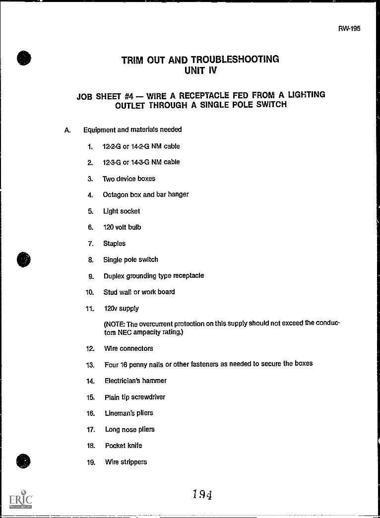
TRIM OUT AND TROUBLESHOOTINGUNIT IV
JOB SHEET #4 - WIRE A RECEPTACLE FED FROM A LIGHTINGOUTLET THROUGH A SINGLE POLE SWITCH
A. Equipment and materials needed
1. 12-2-G or 14-2-G NM cable
2. 12-3-G or 14-3-G NM cable
3. Two device boxes
4. Octagon box and bar hanger
5. Light socket
6. 120 volt bulb
7. Staples
8. Single pole switch
9. Duplex grounding type receptacle
10. Stud wall or work board
11. 120v supply
(NOTE The overcurrent protection on this supply should not exceed the conduc-tors NEC ampacity rating.)
12. Wire connectors
13. Four 16 penny nails or other fasteners as needed to secure the boxes
14. Electrician's hammer
15. Plain tip screwdriver
16. Lineman's pliers
17. Long nose pliers
18. Pocket knife
19. Wire strippers
194
RW-195
I

196
JOB SHEET #4
20. Tool pouch
21. Drill motor or brace
22. 112" or larger wood bit
23. Extension cord
24. Safety glasses
25. GFI
B. Procedure
1. Gather equipment and materials and put on safety glasses.
2. Mount boxes. (Figure 1)
FIGURE 1
-,..............._____5.----"--
0 ILICO=7
--,----s--------r--,----...___r
3. Remove a half inch knockout from the panel.
4. Install cable connector.
195

JOB SHEET #4
5. Bore holes for cable.
(NOTE: Holes should be drilled as close to the center (front to back) of a stud aspossible. Holes should be drilled at least 6 inches above or below the boxdepending on which route is the closest.)
(CAUTION: Be sure and use a GF1 protection.)
6. Run cable between boxes and to panel. (Figure 2)
FIGURE 2
12 or 14-2Gfrom panelto light
12 or 14-2Gfrom switch
toreceptacle
RW-197
(NOTE: Leave at least 8"extending past the surface of device box, and enough toreach the top of panel plus half the width.)
7. Staple cable within 12" of metal boxes, 6" of nonmetallic boxes.
8. Secure all cable clamps and connectors.
(CAUTION: Tighten them until the cable will not slip in the box; overtighteningcan cause an electrical short)
9. Strip cable insulation at device box and panel.
11
;"1 bn n

198
JOB SHEET #4
10. Connect equipment grounding conductors. (Figure 3)
FIGURE 3
11. Make up neutral through the system. (Figure 4)
FIGURE 4
97
,"4-07-5sigi=agittsit=a

JOB SHEET #4
12. Make up switch, return, feed through conductors, and install light fixture. (Figure5)
FIGURE 5
13. Install switch. (Figure 6)
FIGURE 6
RW-199

14. Install receptacle. (Figure 7)
FIGURE 7
Black conductor to brassor dark terminal
Whiteneutral conductorto white orsilver terminal
15. Connect return leg and neutral to light socket.
16. Connect ungrounded conductor. (Figure 8)
FIGURE 8
Connect grounded conductor first
(NOTE: Be sure the breaker is off or the fuse is screwed out before connectingthis conductor. Always be safety conscious.)
17. Turn on breaker or screw in fuse.
18. Turn on switch.
(NOTE: Light should burn.)

e
JOB SHEET #4
19. Test receptacle with test light or V.O.M..
20. Have your instructor evaluate this project.
21. Turn off breaker.
22. Clean work area and put away all equipment and materials.
RW-201

RW-203
TRIM OUT AND TROUBLESHOOTINGUNIT IV
JOB SHEET #5 - CONNECT A SUPPLY CORD TO AFREE STANDING RANGE
A. Equipment and materials needed
1. Screwdriver
2. Appropriate appliance cord
(NOTE: Cord must be acceptable to the NEC and local code enforcing agent.)
3. Free standing range
4. Nut driver set
5. Safety glasses
B. Procedure
1. Gather equipment and materials and put on safety glasses.
2. Position range in best possible working position.
3. Remove appliance terminal cover plate. (Figure 1)
FIGURE 1
4. Install cord securing equipment.
(NOTE: Most range cord sets have a clamp included with the cord.)
5. Connect ungrounded conductors to appropriate terminals.
i 201

204
JOB SHEET #5
6. Connect equipment grounding conductor.
(NOTE: The frame of the range may be grounded to the grounded circuit conduc-tor, providing it is not smaller than a No. 10 copper.)
7. Check cord conductors.
(NOTE: Conductors should be arranged so that a pull on the cord will put tensionon the cord connector, not the appliance terminals.)
8. Replace cover plate.
9. Plug in appliance.
10. Check appliance for correct operation.
(NOTE: Be sure and remove all tape and packing from the oven before testing.Level the oven before you leave.)
11. Clean work area and put away all equipment and materials.
202

RW-205
TRIM OUT AND TROUBLESHOOTINGUNIT IV
JOB SHEET #6 - INSTALL A FIXED APPLIANCE EQUIPPED WITH APIGTAIL TO A BRANCH CIRCUIT
A. Equipment and materials needed
1. Box and cover
(NOTE: Be sure box has a capacity rating to accommodate the conductors beingused.)
2. Fixed appliance with pigtail
(NOTE: Pigtail should consist of flexible metal conduit (greenfield) with propersized conductors for the appliance being connected.)
3. Connectors
(NOTE: The pigtail may have a greenfield connector already on it. A cable con-nector will probably be needed if not internal with the box.)
4. Two #12 x 1" MTS screws
5. Wire connectors
(NOTE: Wire nuts, crimp sleeves, and tape or any other code approved methodarea acceptable.)
6. Screwdriver
7. Pocket knife
8. Wire strippers
9. Safety glasses
B. Procedure
(NOTE: Be sure that the branch circuit you are working around is not hot.)
1. Gather equipment and materials and put on safety glasses.
2. Determine box location.
(NOTE: Be sure and place the box in a location close enough to make the con-nection to the appliance pigtail.)
r.f., 0 3

206
JOB SHEET #6
3. Mount the box.
(NOTE: Be sure the box will not interfere with the installation of the appliance.)
4. Install branch circuit conductors in the box.
5. Position the appliance so the pigtail will reach the box.
6. Connect appliance pigtail to box. (Figures 1 and 2)
FIGURE 1 FIGURE 2Connecting Counter Top Cooking Unit Connecting Range and Receptacle
miffir1)
To Distribution Panel
11---Stud
.4111111
#0.1ary1to NEC
for Wire Site
Refer to NECfor Wire Size
To Distribution Panel
7. Splice appliance supply conductors to branch circuit conductors.
(NOTE: Be sure and make mechanically secure connections.)
8. Install cover plate on box.
9. Position appliance for securing.
10. Activate circuit and check appliance.
11, Rest appliance in its correct position.
(NOTE: Make sure the pigtail is not in a bind.)
12. Secure and level appliance.
13. Clean work area and put away all equipment and materials.

TRIM OUT AND TROUBLESHOOTINGUNIT IV
JOB SHEET #7 - INSTALL A FUSIBLE SAFETY SWITCH FOR ANAIR-CONDITIONING CONDENSER
(NOTE: This job sheet deals only with the mounting of the disconnect. The supply line to theunit is sometimes installed by the air-conditioning installer and sometimes by the electrician.)
A. Equipment and materials needed
1. Pouch tools
2. Raintight fusible safety switch
(NOTE: Size of the switch will be determined by the full load or running amperageof the unit.)
3. Connecting equipment for switch
(NOTE: If this is a new house, a rigid metal conduit or EMT nipple should havebeen installed during the rough-in and should be extending just beyond the sur-face of the exterior wall.)
4. Fasteners
(NOTE: Anchors and screws will be required for brick or concrete; wood screwswill work on wood siding.)
5. Safety glasses
6. Pencil
7. Drill motor and appropriate bit
8. GFI
B. Procedure
(NOTE: Check to be sure the circuii is not live.)
1. Gather equipment and materials and put on safety glasses.
2. Mark mounting holes for switch.
(NOTE: Remember the switch must be within sight of the unit and readily acces-sible. Check the applicable code requirements of NEC Art: 440-14 and 110-16.)
2 0 5
RW-207
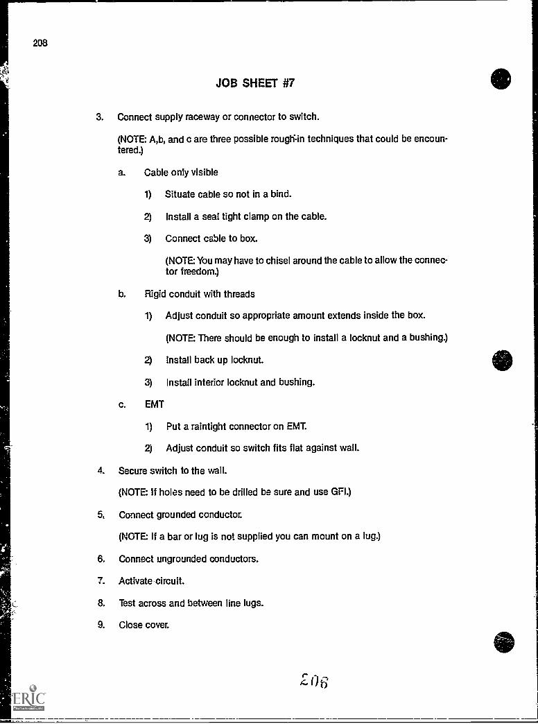
208
JOB SHEET #7
3. Connect supply raceway or connector to switch.
(NOTE: A,b, and c are three possible rough.-in techniques that could be encoun-tered.)
a. Cable only visible
1) Situate cable so not in a bind.
2) Install a seal tight clamp on the cable.
3) Connect cable to box.
(NOTE You may have to chisel around the cable to allow the connec-tor freedom.)
b. Rigid conduit with threads
1) Adjust conduit so appropriate amount extends inside the box.
(NOTE There should be enough to install a locknut and a bushing.)
2) Install back up locknut.
3) Install interior locknut and bushing.
c. EMT
1) Put a raintight connector on EMI
2) Adjust conduit so switch fits flat against wall.
4. Secure switch to the wall.
(NOTE If holes need to be drilled be sure and use GPI.)
5, Connect grounded conductor.
(NOTE If a bar or lug is not supplied you can mount on a lug.)
6. Connect ungrounded conductors.
7. Activate circuit.
8. Test across and between line lugs.
9. Close cover.

RW-209
TRIM OUT AND TROUBLESHOOTINGUNIT IV
JOB SHEET #8 TROUBLESHOOT AN ELECTRICALSYSTEM PROBLEM
(NOTE This is a general job sheet designed to provide practice in using sound troubleshoot-ing procedures.)
A. Equipment and materials needed
1. Pouch tools
2. Volt-ohm-ammeter
3. Safety glasses
4. Auxiliary lighting
B. Procedure
1. Familiarize yourself with the system.
a. Locate supply panel and any subpanels or disconnects.
b. Know system voltage and other data.
c. Trace circuits out mentally and physically if possible.
2. Ask the owner about the problem.
a. Ask about performance prior to the problem.
b. Ask about problem symptoms.
c. Inquire about maintenance procedures.
d. Ask if this problem has happened before.
3. Inspect the system.
a. Look for discolorations on equipment.
b. Smell for unusual odors.
c. Look for frayed cords.
d. Watch for improperly installed or connected appliances.
207

210
JOB SHEET 08
4. Operate the system if safely possible.
a. Turn off switches.
b. Unplug appliances.
c. Check voltages.
5. List possible problem causes.
(NOTE Use your knowledge of the system plus information received from thetroubleshooting techniques used to this point.)
6. Formulate a conclusion.
a. Review list of probable causes.
b. Select cause.
7. Test conclusion.
(NOTE Test the conclusion you have reached before repairing the system if pos-sible.)
#.... i 13

RW-211
TRIM OUT AND TROUBLESHOOTINGUNIT IV
PRACTICAL TESTJOB SHEET #1 - INSTALL A DUPLEX GROUNDING TYPE
RECEPTACLE
STUDENT'S NAME DATE
EVALUATOR'S NAME ATTEMPT NO.
Instructions: When you are ready to perform this task, ask your instructor to observe the pro-cedure and complete this form. All items listed under "Process Evaluation" must receive a"Yes" for you to receive an overall performance evaluation.
PROCESS EVALUATION
(EVALUATOR NOTE Place a check mark in the "Yes" or "No" blanks to designate whether ornot the student has satisfactorily achieved each step in this procedure. If the student isunable to achieve this competency, have the student review the materials and try again.)
The student: YES NO
1. Checked out proper tools and materials.2. Box set out correct for wall covering thickness.3. Holes drilled at proper height and depth.4. Staples for cable spaced properly.5. Care taken during stripping of outer sheath to protect insulation
of conductors from nicks.6. Conductor insulation stripped without nicking conductor.7. Proper connection of conductors made at receptacle.8. Proper connection of conductors made at panel.9. Checked in/put away tools and materials.
10. Cleaned the work area.11. Used proper tools correctly.12. Performed steps in a timely manner ( hrs. _min. _sec.)13. Practiced safety rules throughout procedure.14. Provided satisiactory responses to questions asked.
EVALUATOR'S COMMENTS:
2()
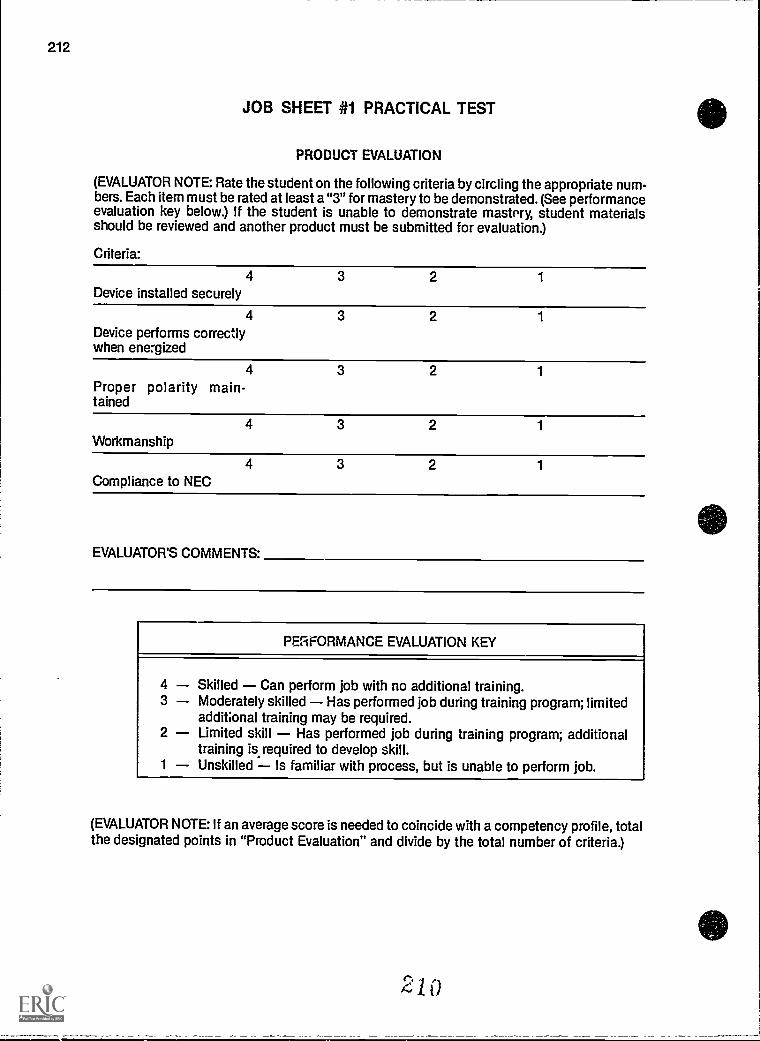
212
JOB SHEET #i PRACTICAL TEST
PRODUCT EVALUATION
(EVALUATOR NOTE: Rate the student on the following criteria by circling the appropriatenum-bers. Each item must be rated at least a "3" for mastery to be demonstrated. (See performanceevaluation key below.) If the student is unable to demonstrate mastery, student materialsshould be reviewed and another product must be submitted for evaluation.)
Criteria:
Device installed securely4 3 2 1
Device performs correctlywhen energized
4 3 2 1
Proper polarity main-tained
4 3 2 1
Workmanship4 3 2 1
Compliance to NEC4 3 2 1
EVALUATOR'S COMMENTS:
PERFORMANCE EVALUATION KEY
4 Skilled Can perform job with no additional training.3 Moderately skilled Has performed job during training program; limited
additional training may be required.2 Limited skill Has performed job during training program; additional
training is required to develop skill.1 Unskilled Is familiar with process, but is unable to perform job.
(EVALUATOR NOTE: If an average score is needed to coincide with a competency profile, totalthe designated points in "Product Evaluation" and divide by the total number of criteria.)

RW-213
TRIM OUT AND TROUBLESHOOTINGUNIT W
PRACTICAL TESTJOB SHEET #2 INSTALL A RANGE OR DRYER RECEPTACLE
STUDENT'S NAME DATE
EVALUATOR'S NAME ATTEMPT NO
Instructions: When you are ready to perform this task, ask your instructor to observe the pro-cedure and complete this form. All items listed under "Process Evaluation" must receive a"Yes" for you to receive an overall performance evaluation.
PROCESS EVALUATION
(EVALUATOR NOTE: Place a check mark in the "Yes" or "No" blanks to designate whether ornot the student has satisfactorily achieved each step in this procedure. If the student isunable to achieve this competency, have the student review the materials and try again.)
The student: YES NO
1. Checked out proper tools and materials.2. Box set out correct for wall covering.3. Holes drilled at proper height and depth.4. Staples for cable spaced properly.5. Care taken during stripping of outer sheath to protect insulation
of conductors from nicks.6. Conductor insulation stripped without nicking conductor.7. Proper connection of conductors made at receptacle.8. Proper connection of conductors made at panel.9. Checked in/put away tools and materials.
10. Cleaned the work area.11. Used proper tools correctly.12. Performed steps in a timely manner (_hrs _min. _sec.)13. Practiced safety rules throughout procedure.14. Provided satisfactory responses to questions asked.
EVALUATOR'S COMMENTS:

214
JOB SHEET #2 PRACTICAL TEST
PRODUCT EVALUATION
(EVALUATOR NOTE: Rate the student on the following criteria by circling the appropriate num-bers. Each item must be rated at least a "3" for mastery to be demonstrated. (See performanceevaluation key below.) If the student is unable to demonstrate mastery, student materialsshould be reviewed and another product must be submitted for evaluation.)
Criteria:
Device installed securely4 3 2 1
Device performs correctlywhen energized
4 3 2 1
Proper polarity main-tained
4 3 2 1
Workmanship4 3 2 1
Compliance to NEC4 3 2 1
EVALUATOR'S COMMENTS:
PERFORMANCE EVALUATION KEY
4 Skilled Can perform job with no additional training.3 Moderately skilled Has performed job during training program; limited
additional training may be required.2 Limited skill Has performed job during training program; additional
training is required to develop skill.1 Unskilled Is familiar with process, but is unable to perform job.
(EVALUATOR NOTE: If an average score is needed to coincide with a competency profile, totalthe designated points in "Product Evaluation" and divide by the total number of criteria.)
r.; i

RW-215
TRIM OUT AND TROUBLESHOOTINGUNIT IV
PRACTICAL TESTJOB SHEET #3 - INSTALL A MULTI-CIRCUIT SPLIT-WIRED
DUPLEX GROUNDING TYPE RECEPTACLE
STUDENT'S NAME DATE
EVALUATOR'S NAME ATTEMPT NO
Instructions: When you are ready to perform this task, ask your instructor to observe the pro-cedure and complete this form. All items listed under "Process Evaluation" must receive a"Yes" for you to receive an overall performance evaluation.
PROCESS EVALUATION
(EVALUATOR NOTE: Place a check mark in the "Yes" or "No" blanks to designate whether ornot the student has satisfactorily achieved each step in this procedure. If the student isunable to achieve this competency, have the student review the materials and try again.)
The student: YES NO
1. Checked out proper tools and materials.2. Box set out correct for wall covering thickness.3. Holes drilled at proper height and depth.4. Staples for cable spaced properly.5. Care taken during stripping of outer sheath to protect insulation
of conductors from nicks.6. Conductor insulation stripped without nicking conductor.7. Proper connection of conductors made at receptacle.8. Connecting fin removed from ungrounded side of receptacle only.9. Proper connection of conductors made at panel.
10. Checked inlput away tools and materials.11. Cleaned the work area.12. Used proper tools correctly.13. Performed steps in a timely manner ( hrs. _min _sec.)14. Practiced safety rules throughout procedure.15. Provided satisfactory responses to questions asked.
EVALUATOR'S COMMENTS
I
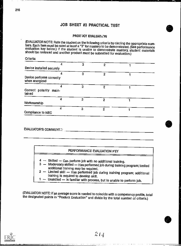
216
JOB SHEET #3 PRACTICAL TEST
PRODUCT EVALUATON
(EVALUATOR NOTE: Rate the studenton the following criteria by circling the appropriate num-bers. Each item must be rated at leasta "3" for mastery to be demonstrated. (See performanceevaluation key below.) If the student is unable to demonstrate mastery, student materialsshould be reviewed and another product must be submitted for evaluation.)
Criteria:
Device installed securely4 3 2 1
Device performs correctlywhen energized
4 3 2 1
Correct polarity main-tained
4 3 2 1
Workmanship4 3 2 1
Compliance to NEC4 3 2 1
EVALUATOR'S COWEN-I:'
PERFORMANCE EVALUATION KEY
4 Skilled Can perform Job with no additional training.3 Moderately skilled Has performed job during training program; limited
additional training may be required.2 Limited skill Has performed job during training program; additional
training is required to develop skill.1 Unskilled Is familiar with process, but is unable to perform job.
(EVALUATOR NOTE: if an average score is needed to coincide with a competency profile, totalthe designated points in "Product Evaluation" and divide by the total number of criteria.)
(2 14

RW-217
TRIM OUT AND TROUBLESHOOTINGUNIT IV
PRACTICAL TESTJOB SHEET #4 - WIRE A RECEPTACLE FED FROM ALIGHTING OUTLET THROUGH A SINGLE POLE SWITCH
STUDENT'S NAME DATE
EVALUATOR'S NAME ATTEMPT NO.
Instructions: When you are ready to perform this task, ask your instructor to observe the pro-cedure and complete this form. All items listed under "Process Evaluation" must receive a"Yes" for you to receive an overall performance evaluation.
PROCESS EVALUATION
(EVALUATOR NOTE: Place a check mark in the "Yes" or "No" blanks to designate whether ornot the student has satisfactorily achieved each step in this procedure. If the student isunable to achieve this competency, have the student review the materials and try again.)
The student: YES NO
1. Checked out proper tools and materials.2. Box set out correct for wall covering thickness.3. Fixture box mounted securely to bar hanger.4. Holes drilled at proper height and depth.5. Staples for cable spaced properly.6. Cable stripped without nicking conductor insulation.7. Conductor insulation stripped without nicking conductor.8. Proper connection of conductors made at fivture.9. Proper connection of conductors made at switch.
10. Proper connection of conductors made at receptacle.11. Checked in/put away tools am, materials.12. Cleaned the work area.i3. Used proper tools correctly.14. Performed steps in a timely manner (_hrs. _min. _sec.)15. Practiced jafety rules throughout procedure.16. Provided satisfactory responses to questions asked.
EVALUATOR'S COMMENTS:

218
JOB SHEET #4 PRACTICAL TEST
PRODUCT EVALUATION
(EVALUATOR NOTE: Rate the student on the following criteria by circling the appropriate num-bers. Each item must be rated at least a "3" for mastery to be demonstrated. (See performanceevaluation key below.) If the student is unable to demonstrate mastery, student materialsshould be reviewed and another product must be submitted for evaluation.)
Criteria:4
Devices installedsecurely
3 2 1
4Fixture installed securel
3 2 1
4Receptacle energizedwith breaker turn on
4Correct polarity main-tained
3 2 1
4Fixture controlled byswitch on/off
3 2 1
4Workmanship
3 2 1
4Compliance to NEC
3 2 1
EVALUATOR'S COMMENTS:
PERFORMANCE EVALUATION KEY
4 Skilled Can perform job with no additional training.3 Moderately skilled Has performed job during training program; limited
additional training may be required.2 Limited skill Has performed job during training program; additional
training is required to develop skill.1 Unskilled Is familiar with process, but is unable to perform job.
(EVALUATOR NOTE: If an average score is needed to coincide with a competency profile, totalthe designated points in "Product Evaluation" and divide by the total number of criteria.)
el ,I 01
,-%f 6

RW219
TRIM OUT AND TROUBLESHOOTINGUNIT IV
PRACTICAL TESTJOB SHEET #5 - CONNECT A SUPPLY CORD TO A
FREE STANDING RANGE
STUDENT'S NAME DATE
EVALUATOR'S NAME ATTEMPT NO
Instructions: When you are ready to perform this task, ask your instructor to observe the pro-cedure and complete this form. All items listed under "Process Evaluation" must receive a"Yes" for you to receive an overall performance evaluation.
PROCESS EVALUATION
(EVALUATOR NOTE: Place a check mark in the "Yes" or "No" blanks to designate whether ornot the student has satisfactorily achieved each step in this procedure. If the student isunable to achieve this competency, have the student review the materials and try again.)
The student: YES NO
1. Checked out proper tools and materiels.2. Cord selected matches appliance load specifications.3. Cord conductor connections made to proper terminals.4. Appliance grounded correctly.5. Cord secured to appliance at connection point.6. Checked in/put away tools and materials.7. Cleaned the work area.8. Used proper tools correctly.9. Performed steps in a timely manner (_hrs. _min. __sec.)
10. Practiced safety rules throughout procedure.11. Provided satisfactory responses to questions asked.
EVALUATOR'S COMMENTS:
217

220
JOB SHEET #5 PRACTICAL TEST
PRODUCT EVALUATION
(EVALUATOR NOTE: Rate the student on the following criteria by circling the appropriate num-bers. Each item must be rated at least a "3" for mastery to be demonstrated. (See per:ormanceevaluation key below.) If the student is onable to demonstrate mastery, student materialsshould be reviewed and another product must be submitted for evaluation.)
Criteria:
4 3 2 1
Appliance operates prop-erly when energized
4 3 2 1
Workmanship
4 3 2 1
Compliance to NEC
EVALUATOR'S COMMENTS:
PERFORMANCE EVALUATION KEY
4 Skilled Can perform Job with no additional training.3 Moderately skilled Has performed Job during training program; limited
additional training may be required.2 Limited skill Has performed Job during training program; additional
training is required to develop skill.1 Unskilled Is familiar with process, but is unable to perform Job.
(EVALUATOR NOTE: If an average score is needed to coincide with a competency profile, totalthe designated points in "Product Evaluation" and divide by the total number of criteria.)

RW-221
TRIM OUT AND TROUBLESHOOTINGUNIT IV
PRACTICAL TESTJOB SHEET #6 - INSTALL A FIXED APPLIANCE EQUIPPED
WITH A PIGTAIL TO A BRANCH CIRCUIT
STUDENT'S NAME DATE
EVALUATOR'S NAME ATTEMPT NO
Instructions: When you are ready to perform this task, ask your instructor to observe the pro-cedure and complete this form. All items listed under "Process Evaluation" must receive a"Yes" for you to receive an overall performance evaluation.
PROCESS EVALUATION
(EVALUATOR NOTE: Place a check mark in the "Yes" or "No" blanks to designate whether ornot the student has satisfactorily achieved each step in this procedure. If the student isunable to achieve this competency, have the student review the materials and try again.)
The student: YES NO
1. Checked out proper tools and materials.2. Proper size box selected.3. Pigtail equipment is sized properly.4. Connections of pigtail (greenfield) secure.5. Appliance is properly grounded.6. Circuit and appliance conductors connected correctly.7. Box cover installed.8. Checked iniput away tools and materials.9. Cleaned the work area.
10. Used proper tools correctly.11. Performed steps in a timely manner ( hrs. _min. _sec.)12. Practiced safety rules throughout procedure.13. Provided satisfactory responses to questions asked.
EVALUATOR'S COMMENTS:
219
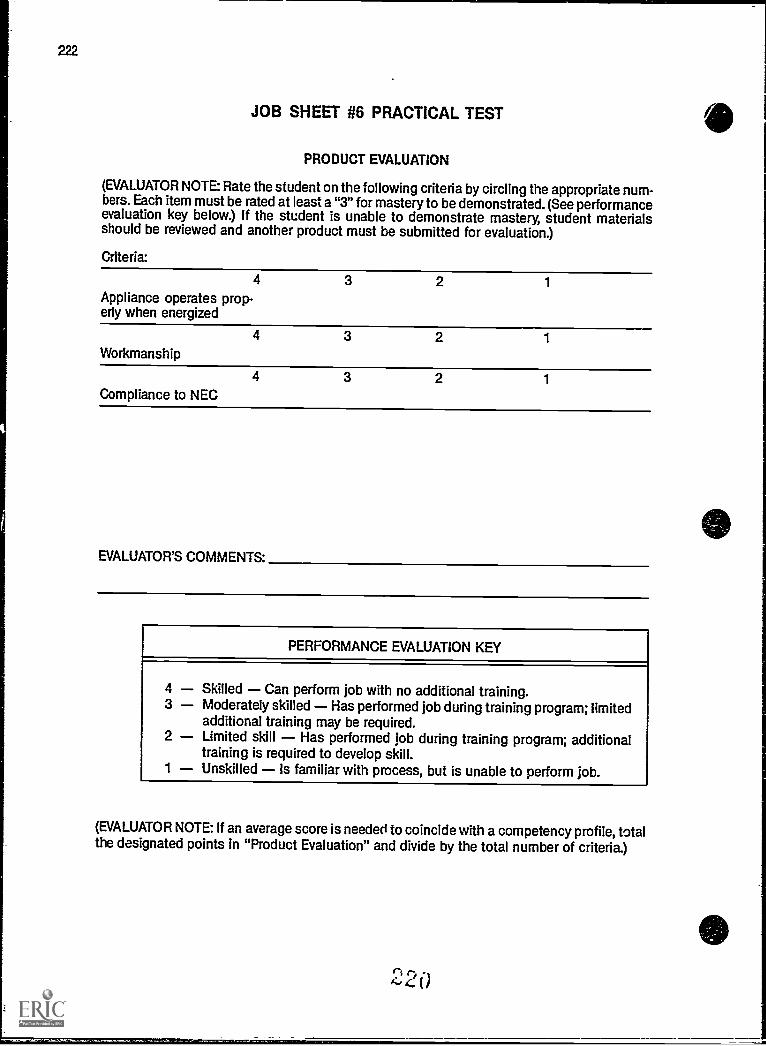
222
JOB SHEET #6 PRACTICAL TEST
PRODUCT EVALUATION
(EVALUATOR NOTE: Rate the student on the following criteria by circling the appropriate num-bers. Each item must be rated at least a "3" for mastery to be demonstrated. (See performanceevaluation key below.) If the student is unable to demonstrate mastery, student materialsshould be reviewed and another product must be submitted for evaluation.)
Criteria:
4 3 2 1
Appliance operates prop-erly when energized
4 3 2 1
Workmanship
4 3 2 1
Compliance to NEC
EVALUATOR'S COMMENTS:
PERFORMANCE EVALUATION KEY
4 Skilled Can perform job with no additional training.3 Moderately skilled Has performed job during training program; limited
additional training may be required.2 Limited skill Has performed job during training program; additional
training is required to develop skill.1 Unskilled is familiar with process, but is unable to perform job.
(EVALUATOR NOTE: If an average score is needed to coincide with a competency profile, totalthe designated points in "Product Evaluation" and divide by the total number of criteria.)
2 0
to 1

RW-223
TRIM OUT AND TROUBLESHOOTINGUNIT IV
PRACTICAL TESTJOB SHEET #7 - INSTALL A FUSIBLE SAFETY SWITCH
FOR AN AIR-CONDITIONING CONDENSER
STUDENT'S NAME DATE
EVALUATOR'S NAME ATTEMPT NO.
Instructions: When you are ready to perform this task, ask your instructor to observe thepro-cedure and complete this form. All items listed under "Process Evaluation" must receive a"Yes" for you to receive an overall performance evaluation.
PROCESS EVALUATION
(EVALUATOR NOTE: Place a check mark in the "Yes" or "No" blanks to designate whether ornot the student has satisfactorily achieved each step in this procedure. If the student isunable to achieve this competency, have the student review the materials and try again.)
The student: YES NO
1. Checked out proper tools and materials.2. Supply raceway connected properly to disconnect switch.3. Switch mounted securely to wall surface.4. Supply conductors connected to correct terminals (supply
should always attach to top terminals).5. Ungrounded conductors connected correctly.6. Grounded conductors connected correctly.7. Grounding conductors connected correctly.8. Checked in/put away tools and materials.9. Cleaned the work area.
10. Used proper tools correctly.11. Performed steps in a timely manner (__hrs. _min. _sec.)12. Practiced safety rules throughout procedure.13. Provided satisfactory responses to questions asked.
EVALUATOR'S COMMENTS:
221

JOB SHEET #7 PRACTICAL TEST
PRODUCT EVALUATION
(EVALUATOR NOTE: Rate the student on the following criteria by circling the appropriatenum-bers. Each item must be rated at least a "3" for mastery to be demonstrated. (See performanceevaluation key below.) If the student is unable to demonstrate mastery, student materialsshould be reviewed and another product must be submitted for evaluation.)
Criteria:
4 3 2 1
Disconnect switchmounted correctly
4 3 2 1
Correct voltage availablewhen circuit energized
4 3 2 1
Workmanship
4 3 2 1
Compliance to NEC
EVALUATOR'S COMMENTS:
PERFORMANCE EVALUATION KEY
4 Skilled Can perform job with no additional training.3 Moderately skilled Has performed job during training program; limited
additional training may be required.2 Limited skill Has performed job during training program; additional
training is required to develop skill.1 Unskilled Is familiar with process, but is unable to perform job.
(EVALUATOR NOTE If an average score is needed to coincide with a competency profile, totalthe designated points in "Product Evaluation" and divide by the total number of criteria.)
222

RW-225
TRIM OUT AND TROUBLESHOOTINGUNIT IV
PRACTICAL TESTJOB SHEET #8 - TROUBLESHOOT AN ELECTRICAL
SYSTEM PROBLEM
STUDENTS NAME DATE
EVALUATOR'S NAME ATTEMPT NO
Instructions: When you are ready to perform this task, ask your instructor to observe the pro-cedure and complete this form. All items listed under "Process Evaluation" must receive a"Yes" for you to receive an overall performance evaluation.
PROCESS EVALUATION
(EVALUATOR NOTE: Place a check mark in the "Yes" or "No" blanks to designate whether ornot the student has satisfactorily achieved each step in this procedure. If the student isunable to achieve this competency, have the student review the materials and try again.)
The student: YES NO
1. Checked out proper tools and materials.2. Followed step by step procedure to trace out circuit.3. Followed step by step questioning procedure as to circuit per-
formance or characteristics prior to problem.4. Checked circuit conductor for insulation breakdown.5. Checked circuit equipment for malfunction.6. Prepared list of probable causes.7. Determined action to correct problem.8. Completed repair or replacement action.9. Checked in/put away tools and materials.
10. Cleaned the work area.11. Used proper tools correctly.12. Performed steps in a timely manner.( hrs. _min. _sec.)13. Practiced safety rules throughout procedure.14. Provided satisfactory responses to questions asked.
EVALUATOR'S COMMENTS:
00

226
JOB SHEET #8 PRACTICAL TEST
PRODUCT EVALUATION
(EVALUATOR NOTE: Rate the student on the following criteria by circling the appropriate num-bers. Each item must be rated at least a "3" for mastery to be demonstrated. (See performanceevaluation key below.) If the student is unable to demonstrate mastery, student materialsshould be reviewed and another product must be submitted for evaluation.)
Criteria:
4 3 2 1
Source of problemlocated
4 3 2 1
Circuit returned to normal
4 3 2 1
Workmanship
4 3 2 1
Compliance to NEC
EVALUATOR'S COMMENTS'
PERFORMANCE EVALUATION KEY
4 Skilled Can perform job with no additional training.3 Moderately skilled Has performed job during training program; limited
additional training may be required.2 Limited skill Has performed job during training program; additional
training is required to develop skill.1 Unskilled Is familiar with process, but is unable to perform job.
(EVALUATOR NOTE: If an average score is needed to coincide with a competency profile, totalthe designated points in "Product Evaluation" and divide by the total number of criteria.)
el -4,c,4

TRIM OUT AND TROUBLESHOOTINGUNIT IV
TEST
NAME SCORE
1. Match the terms on the right with their correct definitions.
a Conductor that carries electrical energyfrom the switch to the load
b. The use of a box for splicing or reroutingconductors to get to another location
c Utilization equipment, generally other thanindustrial, normally built in standardizedsizes or types, which is installed or con-nected as a unit to perform one or morefunctions such as clothes washing, air con-ditioning, food mixing, or deep frying
d A single device with two or more recepta-cles
e The systematic diagnosis of a malfunction
f Conductors between light and switch whensupply enters the light
g A device, or group of devices, or othermeans by which the conductors of a circuitcan be disconnected from their source ofsupply
h Point of attachment for conductors
i Metal strip containing one or more devices
j A single device with two grounding typereceptacles
k Transfer conductors in a switching situa-tion; they are used between 3-ways and 4-ways
I Receptacle that has had a connecting finremoved for remote control or separate cir-cuit connections
225
1. Appliance
2. Appliance branch cir-cuit
3. Cable clamp
4. Device
5. Disconnecting means
6. Duplex groundingreceptacle
7. Feed through
8. Individual branch cir-cuit
9. Multiple receptacle
10. Pigtail
11. Poles
12. Receptacle connect-ing fin
13. Line leg
14. Single receptacle
15. Split-wired receptacle
RW-227

228
TEST
m. Voltage multiplied times amperage 16. Strap or yoke
n Unit of an electrical system which is 17. Switchintended to carry but not utilize electricalenergy 18. Switch leg
o. Detachable design feature that makes ter- 19. Switch loopminals common connections
20. Terminalp. Conductor that supplies electrical energy to
a switch 21. Traveler
q. Current carrying conductors, both grounded 22. Trim outand ungrounded, on a receptacle
23. Troubleshootingr. Branch circuit that supplies only one piece
of utilization equipment 24. Volt ampere
s. A branch circuit supplying energy to one or 25. Wiresmore outlets to which appliances are to beconnected
_t. Splicing technique that leaves an accessi-ble conductor for termination at a device,load, or grounding terminal
u. Device used to open or transfer circuit direc-tion
v. Piece of equipment used to secure cables
w. Final stage in a residential wiring project;involves devices and plates, connecting andsecuring equipment, hanging fixture, andtesting the system
____x. Current carrying conductors and groundingconductors
y. A single contact device with no other con-tact device on the same yoke
2 2 6

RW-229
TEST
2. Identify common residential receptacle types and cover plates shown below.
(76?
00
a.
C.
K)1 ©
00
e f.
227

g. h.
3. Identify common residential switch types and cover plates shown below.
a. b.
c. d.

00
TEST
e. f.
9.
0
0
0
a....
h.
0
0
229
RW-231

232
TEST
4. Match common residential fixture locations on the right with their correct types.
a
b
c.
d.
1
IIEV`,E11
1. Dining room
2. Bedroom or hall
3. Recessed fixturesand trims
4. Bathroom
5. Closet
6. Outdoor entry
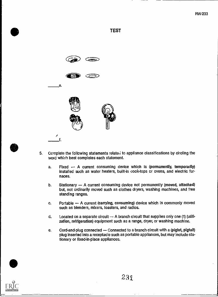
I,-
e
,f
--_-__7-3-
TEST
5. Complete the following statements relate.; to appliance classifications by circling theword which best completes each statement.
a. Fixed A current consuming device which is (pormanently, temporarily)installed such as water heaters, built-in cooktops or ovens, and electric fur-naces.
b. Stationary A current consuming device not permanently (moved, attached)but, not ordinarily moved such as clothes dryers, washing machines, and freestanding ranges.
c. Portable A current (carrying, consuming) device which is commonly movedsuch as blenders, mixers, toasters, and radios.
d. Located on a separate circuit A branch circuit that supplies only one (1) (utili-zation, refrigeration) equipment such as a range, dryer, or washing machine.
e. Cord-and-plug connected Connected to a branch circuit with a (piglet, pigtail)plug inserted into a receptacle such as portable appliances, but may include stationary or fixed-in-place appliances.
231
RW-233

234
TEST
6. Distinguish between requirements for appliance disconnect means by placing an "X"for permanently connected appliances next to the correct requirement.
a. An accessible plug and receptacle shall be permitted to serve as the dis-connect means.
b. The branch circuit breaker shall be permitted to serve as the disconnect-ing means where readily accessible to the user of the appliance.
7. State the grounding requirement for appliances.
8. Identify the parts of a duplex grounding type receptacle.
r
a
d
r':10,...14,D

RW-235
TEST
9. Identify the parts of an equipment grounding system.
g
f.
10. Arrange in order the steps for panel trim out by placing a "1" for the first step, a "2" forthe second step and so on in the blanks preceding the steps.
a Connect ungrounded conductors to their overcurrent protection devices.
b. Label panel in the form of a directory.
c Connect the grounding conductors to their panel location.
d Energize the system with temporary power.
e. Connect grounded conductors to the panel neutral bar.
223

236
TEST
11. Select true statements concerning troubleshooting procedures by placing an "X" in theblanks preceding the true statements.
a. Consulting the owner about the operation of a system may help to deter-mine symptoms of a problem causing system.
b Locate the problem solving area by turning on the power and waiting forsmoke to indicate where the problem is.
c Check the conductor to see if it is discolored from overheating or if theinsulation is damaged or nicked.
d. Replace fuse or circuit breaker with a larger size to eliminate breaker trip.
e Check devices and fixtures for worn or overheated parts.
f. Repair or replace cause of problenh
(NOTE: If the following activities have not been accomplished prior to the test, ask yourinstructor when they should be completed.)
12. Demonstrate the ability to:
a Install a duplex grounding type receptacle. (Job Sheet #1)
b. Install a range or dryer receptacle. (Job Sheet #2)
c. Install a multi-circuit split-wired duplex grounding type receptacle. (Job Sheet #3)
d. Wire a receptacle fed from a lighting outlet through a single pole switch. (JobSheet #4)
e. Connect a supply cord to a free standing range. (Job Sheet #5)
f. Install a fixed appliance equipped with a pigtail to a branch circuit. (Job Sheet #6)
g. Install a fusible safety switch for an air-conditioning condenser. (Job Sheet #7)
h. Troubleshoot an electrical system problem. (Job Sheet #8)
'234
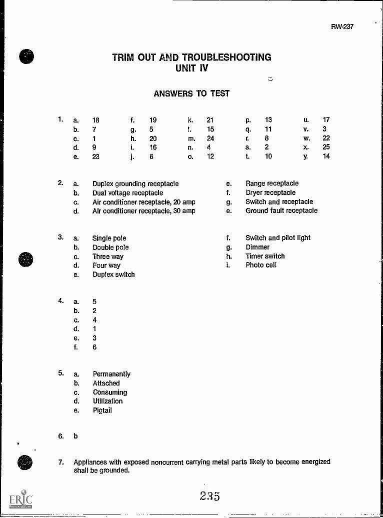
RW-237
2. a.b.c.d.
3. a.b.c.d.e.
4. a.b.c.d.e.f.
5. a.b.
c.d.e.
6. b
18
71
923
TRIM OUT AND TROUBLESHOOTINGUNIT IV
f.
9.h.i.
i.
ANSWERS TO TEST
19
52016
6
k.
I.
m.n.
o.
Duplex grounding receptacleDual voltage receptacleAir conditioner receptacle, 20 ampAir conditioner receptacle, 30 amp
Single poleDouble poleThree wayFour wayDuplex switch
5241
36
PermanentlyAttachedConsumingUtilizationPigtail
21
15
24412
e.f.
9.e.
P.
q.r.
s.t.
13
11
8210
u.v.
w.x.y.
Range receptacleDryer receptacleSwitch and receptacleGround fault receptacle
f. Switch and pilot lightg. Dimmerh. Timer switchi. Photo cell
17
3222514
7. Appliances with exposed noncurrent carrying metal parts likely to become energizedshall be grounded.

238
ANSWERS TO TEST
8. a. Mounting hole f. Ground slotb. Mounting bracket g. Grounding terminalc. Live slot h. Neutral terminalsd. Live terminals i. Bridgee. Cover mounting screw j. Neutral slot
9. a. Grounding connection at frameb. Receptacle grounding slotc. Attachment cap grounding prongd. Neutral blocke. Grounding electrode conductorf. Grounding electrodeg. Grounding conductor
10. a. 3b. 4c. 1
d. 5e. 2
11. a, c, e, f
12. Performance skills evaluated to the satisfaction of the instructor
RW-239
LOAD CENTER CHANGESUNIT V
UNIT OBJECTIVE
After completion of this unit, the student should be able to change out existing load centers oradd supplemental load centers to existing panels. Competencies will be demonstrated bycompleting the job sheets and the unit tests with a minimum score of 85 percent.
SPECIFIC OBJECTIVES
After completion of this unit, the student should be able to:
1. Match terms related to load center changes with their correct definitions.
2. Describe the three basic types of load centers.
3. Match reasons for load center changes with their correct causes.
4. List possible ways to increase service size on an existing dwelling.
5. Select true statements concerning procedures for changing existing service.
6. Demonstrate the ability to:
a. Replace an existing interior flush mount load center. (Job Sheet #1)
b. Install a rainproof load center to supplement an existing interior load cen-ter. (Job Sheet #2)
227

LOAD CENTER CHANGESUNIT V
SUGGESTED ACTIVITIES
A. Obtain additional materials and/or invite resource people to class to supplement/rein-force information provided in this unit of instruction.
(NOTE This activity should be completed prior to the teaching of this unit.)
B. Provide students with objective sheet.
C. Discuss unit and specific objectives.
D. Provide students with information sheet.
E. Discuss information sheet.
F. Provide students with job sheets.
G. Discuss and demonstrate the procedures outlined in the job sheets.
H. Integrate the following activities throughout the teaching of this unit:
1. Contact local utility company representative to visit class to discuss requirementsfor electricians disconnecting or reconnecting service drop conductors.
2. Contact local code enforcement representative to visit class to discuss local regu-lations regarding inspection requirements for service change outs.
3. Construct trainer boards to simulate existing service riser and panel installationsto be changed out in these job sheets.
4. Contact local contractor to arrange job site visit for class to witness a live workchange out.
5. Meet individually with students to evaluate their progress through this unit ofinstruction, and indicate to them possible areas of improvement.
I. Give test.
J. Evaluate test.
K. Reteach if necessary.
228
RW-241

242
REFERENCES USED WRITING THIS UNIT
A. Taylor, Mark. Residential Wiring. Revised. Stillwater, OK: Mid-America Vocational Curric-ulum Consortium, 1983.
B. National Electrical Code, 1987. Quincy, MA: National Fire Protection Azsociation, 1986.
SUGGESTED SUPPLEMENTAL MATERIAL
Text Holzman, Harvey W. Modern Residential Wiring. South Holland, IL: Goodheart-Wilcox Co., Inc., 1986. 123 W. Taft Dr. South Holland, IL 60473.
(NOTE: This text may be obtained by writing to Goodheart-Wilcox Co., Inc., 123W. Taft Dr., South Holland, IL 60473.)
219

LOAD CENTER CHANGESUNIT V
INFORMATION SHEET
L Terms and definitions
A. Aircondit :.wing condenser Refrigeration equipment that sits outside aresidential dwelling and is used to remove heat from refrigerant; usuallycontains a hermetically sealed compressor
B. Full load amps (F.L.A.) Amperage at which equipment is designed tooperate
(NOTE: This information can usually be found on the equipment name-plate.)
C. Life sustaining medical equipment Equipment necessary to keeppatients alive
(NOTE: This could be an iron lung, kidney machine or any other machineused to replace or sustain a bodily function.)
D. Load center A factory assembled metal cabinet consisting of fuses orcircuit breakers for overcurrent protection of electrical wiring
E. Outage Period during which no current is available to circuits in a resi-dential dwelling
F. Premises wiring The interior and exterior wiring including power, light-ing, control and signal circuits together with associated hardware, fittings,and wiring devices
II. Basic types of load centers
A. Flush interiorwall covering
B. Surface interiordwelling
C. Surface exteriordwelling
Mounted behind wall covering with opening flush with the
Mounted on the surface of the wall covering inside the
Mounted on the surface of the wall covering outside the
240
RW-243

244
INFORMATION SHEET
III. Reasons for load center changes
A. Load center changes with no structural changes
1. Addition of window air conditioner unit or central air conditioningunit.
2. Addition of increased laundry load (electric clothes dryer)
3. Addition of increased kitchen loads (microwave oven, garbage dis-posal, etc.)
4. Change out worn out antiquated load center
B. Load center change' with structural changes
1. Room additions to existing dwellings (extra bedroom, utility room,den, or family center)
2. Remodel existing dwelling (new kitchen, wall removal, or refurbishinterior walls)
3. Addition of a deck area for swimming pool or hot tub
(NOTE: Any change made to existing dwelling exceeding 50% remodel willrequire that the premises wiring be brought up to existing code standards.)
IV. Possible ways to increase existing service size
A. Install larger service entrance conductors in existing raceway, and increaseload center main breaker size accordingly.
(NOTE: This method will only work if the raceway is large enough, the loadcenter bus is rated for increased size, and the main breaker is interchange-able and the panel has sufficient space for additional circuit breakers.)
B. Increase service conductor size and set a new exterior load center withmain breaker sized to supply new and existing loads.
(NOTE: Raceway must be changed if it is not rated for increased conductorsize. A separate breaker must be installed in the new exterior panel to feedthe old panel as a subpanel.)
C. Make a complete service change out.
(NOTE: This the most extensive change and must include all new equip-ment (service raceway and conductor and load center.)
4 i 1rt

RW-245
INFORMATION SHEET
V. Procedures for changing an existing service
(NOTE: Always check with local utility company and code enforcement authoritybefore starting.)
A. Calculate new service size needed.
(NOTE: It is possible to use Unit I, Blueprint Reading and Load Calcula-tions, for sizing the new service.)
B. Estimate materials and labor needed.
(NOTE: This involves exact calculation of material cost [plus mark-up] andestin.ated labor cost to install the materials. Do not forget to include in esti-mate any permit or inspection fees for local code enforcement compliance.)
C. Consult with customer about bes )ossible time to do the work.
(NOTE: Be sure no life sustaining medical equipment is involved in the out-age. In extreme summer heat, this may include air conditioning units.)
D. Contact utility company and local code enforcement authority about theproject.
(NOTE: The utility company may require inspection by the local codeenforcement officer before reconnecting the service conductors to the serv-ice drop conductors. They may even need to increase their service dropconductors size.)
E. Start and complete load center and service change out.
(NOTE: Be prepared to finish this project once you start unless the dwellingis unoccupied.)
242

LOAD CENTER CHANGESUNIT V
JOB SHEET #1 - REPLACE AN EXISTING,INTERIOR FLUSHMOUNT LOAD CENTER
(NOTE: This job sheet is intended to provide instruction on removing an inadequate or defec-tive load center and replacing it with an appropriate new one. Riser, meter base, and other
ervice equipment will not be dealt with due to the number of variables involved.)
(CAUTION: This Job should be done on a trainer board, not on a live job site.)
A. Equipment and materials needed
1. Pouch tools
2. Keyhole saw
3. Hacksaw blade or nail saw
4. Load center with flush cover
(NOTE: If you are increasing the size of the load center use Example No. 1, 1[a],1[b], or 1[c], from the tables and examples in the back of the NEC to compute thesize needed.)
5. Drop cloth
6. Knockout cutter set
(NOTE: If the load center you are changing is fed through a nipple from the meterbase and it can be aligned with existing KO's in the new load center you will notneed this equipment)
7. Safety glasses
8. Voltmeter
9. Metal tapping screws or pan head wood screws
(NOTE: The length of these screws will be determined by the distance betweenthe panel and the stud. Shims may be needed.)
10. Portable GFI
243
RW-247

248
--"==
B. Procedure
---
JOB SHEET #1
(NOTE: This project must be completed once started. Check with the customer to findwhen it would be of least inconvenience to have the electricity off for this operation. Besure there is not any life sustaining medical equipment involved in this outage. Haveemergency lighting available.)
1. Gather equipment and materials.
(NOTE: Chock to be sure you have every possible item needed to finish the jobonce you start. Contact utility company. They may want to remove the meter.)
2. Put on safety glasses.
3. Remove load center cover screws.
4. Remove load center cover.
(NOTE: Place the cover out of your working area.)
5. Turn off or pull existing main.
(NOTE: Nc.:;fy the customer that there will be an outage before disconnectingpower.)
6. Puii the meter.
(NOTE: Turning off the main(s) eliminates an arc during this process.)
7. Remove fasteners securing load center to studs.
(CAUTION: If it is secured by screws, use extreme care when working aroundload center interior.)
(NOTE: Use hacksaw blade with tape for a handle or a nail saw to cut nailsbetween load center and stud.)
8. Trace outline for new ioad center.
a. Hold new load center over existing one.
(NOTE: Match up knockouts so your panei will fit over existing feeder raceway.You may have to cut an opening.)
244

JOB SHEET #1
b. Draw around bad center once it is in place. (Figure 1)
(NOTE: Make opening about 1/4" large on top and bottom of the panel.)
FIGURE 1
r 1
Outline for New Box
1=3017CEIMIX1
L J
---S-Stud Side
9. Cut opening for new load center.
a. Cut lightly along line with knife.
b. Repeat cuts until cut is over one half way through plasterboard.
(NOTE: Do not use a saw until it is evident there are no wires that could be cut.)
c. Break out plasterboard.
(NOTE: Dress the opening with the keyhole saw.)
10. Disconnect the service entrance conductors from the load center line lugs.
11. Disconnect the grounded conductor.
(NOTE: Grounded conductors are always last off and first back on for safety pur-poses.)
12. Disconnect all wires from branch circuit breakers.
(NOTE: Label all circuits so you can update new circuit directory.)
13. Disconnect all grounded and grounding wires from block.
14. Remove all locknuts and bushings.
245

250
JOB SHEET #1
15. Slip all branch circuit cables out of load center.
(NOTE: This may not be possible until you start pulling the panel from the open-ing.)
16. Pull load center out of opening.
17. Lay old load center out of the way.
18. Punch out appropriate KO's for feeder and branch circuits.
19. Hold panel up to opening.
20. Start branch circuit cables into openings. (Figure 2)
(NOTE: Readjust cable connectors before starting cables into the panel.)
FIGURE 2
21. Feed cables In as you move the load center into place.
(NOTE: Proceed carefully so you do not damage any cables.)
22. Guide service entrance conductors into opening.
23. Move load center Into place.
(NOTE: Some installations may require mat frame or trim.)

to
JOB SHEET #1
24. Replace locknut and bushing.
(NOTE: Bond equipment according to the NEC and local codes.)
25. Secure load center.
(NOTE: Screws are recommended for this job.)
26. Reconnect service neutral.
27. Reconnect ungrounded service entrance conductors.
(NOTE: If these conductors are not long enough, replace them.)
28. Reconnect branch circuits.
(NOTE: Be sure and hook conductors to appropriate size breaker.)
29. Turn all disconnects off.
30. Replace meter.
31. Turn on main(s).
32. Turn on branch circuit.
33. Check circuits.
34. Put all covers and trims in place.
35. Clean work area and put away all equipment and materials.
247
RW-251
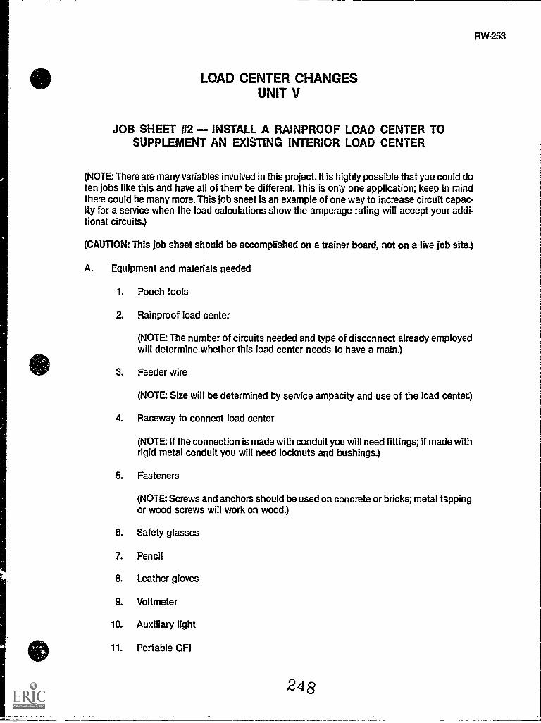
RW-253
LOAD CENTER CHANGESUNIT V
JOB SHEET #2 - INSTALL A RAINPROOF LOAD CENTER TOSUPPLEMENT AN EXISTING INTERIOR LOAD CENTER
(NOTE: There are many variables involved in this project. It is highly possible that you could doten jobs like this and have all of them be different. This is only one application; keep in mindthere could be many more. This job sneet is an example of one way to increase circuit capac-ity for a service when the load calculations show the amperage rating will accept your addi-tional circuits.)
(CAUTION: This job sheet should be accomplished on a trainer board, not on a live job site.)
A. Equipment and materials needed
1. Pouch tools
2. Rainproof load center
(NOTE The number of circuits needed and type of disconnect already employedwill determine whether this load center needs to have a main.)
3. Feeder wire
(NOTE Size will be determined by service ampacity and use of the load center.)
4. Raceway to connect load center
(NOTE If the connection is made with conduit you will need fittings; if made withrigid metal conduit you will need locknuts and bushings.)
5. Fasteners
(NOTE: Screws and anchors should be used on concrete or bricks; metal tappingor wood screws will work on wood)
6. Safety glasses
7. Pencil
8. Leather gloves
9. Voltmeter
10. Auxiliary light
11. Portable GFI
248

254
JOB SHEET #2
12. Drill motor and masonry bit
13. Leather gloves
14. Wooden ladder
15. Sbivice connectors
(NOTE If the utility company disconnects the drop, these will not be needed.)
16. Close nipple
(NOTE The size of this equipment will be determined by the size of the conduc-tors to be installed.)
17. Four locknuts to fit nipple
18. Two bushings to fit nipple
19. Feeder wire
(NOTE:This includes L igrounded and grounded; size will be determined by serv-ice size.)
B. Procedure
(NOTE Contact the utility company before you start this project. They may want to dis-connect the service drop from the service entrance conductors.)
1. Gather equipment and materials.
2. Put on safety glasses.
3. Notify customer that there will be a temporary outage.
(NOTE: Make sure you will not be disrupting the operation of any life sustainingequipment.)
4. Disconnect the service drop.
a. Work from a wooden ladder.
b. Wear gloves.
c. Disconnect one conductor at a time.
d. Tape conductors as you remove them.
e. Remove neutral last.
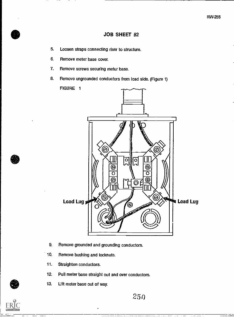
JOB SHEET #2
5. Loosen straps connecting riser to structure.
6. Remove meter base cover.
7. Remove screws securing meter base.
8. Remove ungrounded conduciors from load side. (Figure 1)
FIGURE 1
Load Lug
9. Remove grounded and grounding conductors.
10. Remove bushing and locknuts.
11. Straighten conductors.
12. Pull meter base straight out and over conductors.
13. Lift meter base out of way.
250
Load Lug
RW-255

256
JOB SHEET #2
14. Remove appropriate KO from load center.
(NOTE: If it is going to put the meter higher than the utility company will alowwhen you use a bottom KO use a top one instead. You may have to cut a newone.)
15. Put load center over conductors.
16. Mark securing screw locations.
17. Mount the load center.
(NOTE: Be sura and use GFI if holes are to be drilled.)
18. Install locknuts and bushings.
(NOTE: Check on bonding requirements with local utility company.)
19. Install nipple between load center and meter base using backup locknuts on theoutside of both enclosures.
(NOTE It may be that you will have to mount the meter base to the side of yourpanel instead of above it. See Figure 2. Look the situation over carefully beforeyou decide.)
FIGURE 2
20. Secure meter base.
21. Install interior locknuts and bushings.
(NOTE Check with local utility company on bonding requirements.)
22. Install conductors between existing panel and new load center.
(NOTE Size is determined by load and equipment calculations. Provide overcur-rent protection for existing panel from new load center.)

JOB SHEET #2
23. Install conductors between meter load lugs and new load center line lugs.
24. Reconnect grounding electrode conductor.
25. Resecure service riser.
26. Reconnect service drop.
(NOTE: Consult your local utility company; they may want to do this. Alwaysremember:
a Grounded conductor is last off and first back on.
b. Wear gloves.
c. Work one conductor at a time.
d. Tape conductor as it is connected.
e. Don't carry extra tools in your hands.
f. Work from a wooden ladder.)
27. Turn off main breaker(s).
28. Install meter.
29. Turn on breakers.
30. Check circuits.
31. Update circuit directory.
32. Clean work area and put away all equipment and materials.
252

RW-259
LOAD CENTER CHANGESUNIT V
PRACTICAL TESTJOB SHEET #1 - REPLACE AN EXISTING INTERIOR
FLUSH MOUNT LOAD CENTER
STUDENTS NAME DATE
EVALUATOR'S NAME ATTEMPT NO
Instructions: When you are ready to perform this task, ask your instructor to observe the pro-cedure and complete this form. All items listed under "Process Evaluation" must receive a"Yes" for you to receive an overall performance evaluation.
PROCESS EVALUATION
(EVALUATOR NOTE: Place a check mark in the "Yes" or "No" blanks to designate whether ornot the student has satisfactorily achieved each step in this procedure. If the student isunable to achieve this competency, have the student review the materials and try again.)
The student: YES NO
1. Checked out proper tools and materials.2. All circuits turned off (including main).3. Meter removed before beginning removal of panel.4. Care taken to protect existing branch circuit conductors.5. Care taken to protect existing service conductors.6. All circuit conductors re-enter panel (none folded back).7. Existing grounding conductor re-enter panel.8. Service conductors attached proper lugs.9. Branch circuit conductor attached to proper breakers and lugs
(neutral).10. Bonding accomplished between service and new load center.11. Checked inlput away tools and materials.12. Cleaned the work area.13. Used proper tools correctly.14. Performed steps in a timely manner (___hrs. _min _sec.)15. Practiced safety rules throughout procedure.16. Provided satisfactory responses to questions asked.
EVALUATOR'S COMMENTS:
253
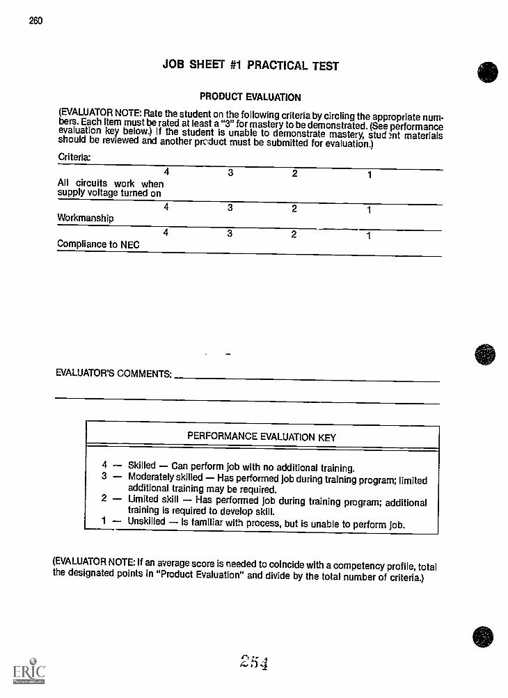
260
JOB SHEET #1 PRACTICAL TEST
PRODUCT EVALUATION
(EVALUATOR NOTE: Rate the student on the following criteria by circling the appropriate num-bers. Each item must be rated at least a "3" for mastery to be demonstrated. (See performanceevaluation key below.) If the student is unable to demonstrate mastery, student materialsshould be reviewed and another prc:duct must be submitted for evaluation.)
Criteria:
4 3 2 1All circuits work whensupply voltage turned on
4 3 2 1
Workmanship
4Compliance to NEC
3 2
EVALUATOR'S COMMENTS:
PERFORMANCE EVALUATION KEY
4 Skilled Can perform job with no additional training.3 Moderately skilled Has performed job during training program; limited
additional training may be required.2 Limited skill Has performed job during training program; additional
training is required to develop skill.1 Unskilled Is familiar with process, but is unable to perform job.
(EVALUATOR NOTE: If an average score is needed to coincide with a competency profile, totalthe designated points in "Product Evaluation" and divide by the total number of criteria.)
254

RW-261
LOAD CENTER CHANGESUNIT V
PRACTICAL TESTJOB SHEET #2 - INSTALL A RAINPROOF LOAD CENTERTO SUPPLEMENT AN EXISTING INTERIOR LOAD CENTER
STUDENT'S NAME DATE
EVALUATOR'S NAME ATTEMPT NO.
Instructions: When you are ready to perform this task, ask your instructor to observe the pro-cedure and complete this form. All items listed under "Process Evaluation" must receive a"Yes" for you to receive an overall performance evaluation.
PROCESS EVALUATION
(EVALUATOR NOTE: Place a check mark in the "Yes" or "No" blanks to designate whether ornot the student has satisfactorily achieved each step in this procedure. If the student isunable to achieve this competency, have the student review the materials and try again.)
The student: YES NO
1. Checked out proper tools and materials.2. Caution used to protect existing load conductor insulation.3. Proper size and location K.O. removed.4. Lock nut and bushing reconnected securely.5. Proper size conductors installed between existing panel and new
panel.6. Proper size conductors installed between meter and new load
center.7. Proper size conductors installed in service raceway.8. Service raceway and meter secured properly.9. Checked in/put away tools and materials.
10. Cleaned the work area.11. Used p -oper tools correctly.12. Performed steps in a timely manner (_hrs _min. _sec.)13. Practiced safety rules throughout procedure.14. Provided satisfactory responses to questions asked.
EVALUATOR'S COMMENTS:
255

262
JOB SHEET #2 PRACTICAL TEST
PRODUCT EVALUATION
(EVALUATOR NOTE: Rate the student on the following criteria by circling the appropriate num-bers. Each item must be rated at least a "3" for mastery to be demonstrated. (See performanceevaluation key below.) If the student is unable to demonstrate mastery, student materialsshould be reviewed and another product must he submitted for evaluation.)
Criteria:
3
All equipment connec-tions made securely
2 1
4 3 2 1
All circuits work properlywhen energized
4 3 2 1
Workmanship
4 3 2 1
Compliance to NEC
EVALUATOR'S COMMENTS:
PERFORMANCE EVALUATION KEY
4 Skilled Can perform job with no additional training.3 Moderately skilled Has performed job during training program; limited
additional training may be required.2 Limited skill Has performed job during training program; additional
training is required to develop skill.1 Unskilled Is familiar with process, but is unable to perform job.
(EVALUATOR NOTE: If an average score is needed to coincide with a competency profile, totalthe designated points in "Product Evaluation" and divide by the total number of criteria.)
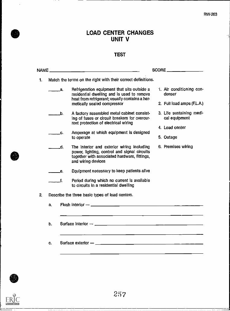
RW-263
LOAD CENTER CHANGESUNIT V
TEST
NAME SCORE
1. Match the terms on the right with their correct definitions.
a. Refrigeration equipment that sits outside aresidential dwelling and is used to removeheat from refrigerant; usually contains a her-metically sealed compressor
b A factory assembled metal cabinet consist-ing of fuses or circuit breakers for overcur-rent protection of electrical wiring
c
d
e
f.
Amperage at which equipment is designedto operate
The interior and exterior wiring includingpower, lighting, control and signal circuitstogether with associated hardware, fittings,and wiring devices
Equipment necessary to keep patients alive
Period during which no current is availableto circuits in a residential dwelling
2. Describe the three basic types of load centers.
1. Air conditioning con-denser
2. Full load amps (F.L.A.)
3. Life sustaining medi-cal equipment
4. Load center
5. Outage
6. Premises wiring
a. Flush interior
b. Surface interior
c. Surface exterior
257

3.
TEST .
Match reasons for load center changes on the right with their correct causes ofincreased load.
a Addition of window air conditioner 1. Load center changeswith no structural
b. Increased kitchen loads (microwave and dis-poser)
change
2. Load center changesc Utility room addition
Remodel kitchen
Install electric clothes dryer
New deck with hot tubs
withchange
structural
d
e
f.
4. List threo possible ways to increase service size on an existing dwelling.
a.
b.
c.
5. Select true statements concerning procedures forchanging an existing service by plac-ing an "X" in the blanks preceding the true statements.
a.
b.
c
Calculate new service size needed.
Estimate materials and labor needed.
Consult with customer about best possible time to do the work.
d. Contact utility company and local code enforcement authority about theproject.
e Start load center and service change out on occupied dwelling and com-plete at your convenience.
(NOTE: If the following activities have not been accomplished prior to the test, ask yourinstructor when they should be completed.)
6. Demonstrate the ability to:
a. Replace an existing interior flush mount load center. (Job Sheet #1)
b. install a rainproof load center to supplement an existing interior load center. (JobSheet #2)
44-43p3,5::',e1
,

LOAD CENTER CHANGESUNIT V
ANSWERS TO TEST
1. a. 1 d. 6b. 4 e. 3c. 2 f. 5
2. a. Flush interior Mounted behind wall covering with opening flush with the wallcovering
b. Surface interior Mounted on the surface of the wall covering inside the dwell-ing
c. Surface exterior Mounted on the surface of the wall covering outside thedwelling
3. a. 1 d. 2
b. 1 e. 1
c. 2 f. 2
4. a. Install larger service entrance conductors in existing raceway and increase loadcenter main breaker size accordingly.
b. Increase service conductor size and set a new exterior load center with mainbreaker sized to supply new and existing loads.
c. Make a complete service change out.
5. a, b, c, d
6. Performance skills evaluated to the satisfaction of the instructor
259
RW-265