DOCUMENT RESUME ED .246 218 CE 039 203 · RCL circuits (19), parallel RCL circuits (8),...
350
DOCUMENT RESUME ED .246 218 CE 039 203 TITLE Electronic Principles III, 7-7. Military Curriculum Materials for Vocational and Technical Education. INSTITUTION Air Force Training Commands Kessler AFB, Miss.; Ohio State Univ., Columbus, National Center for Research in Vocational Education. SPONS AGENCY Department of Education, Washington, DC. PUB DATE 75 NOTE 353p.; Portions of Plan of Instruction may be marginally legible due to poor print quality. For related documents, see CE 039 201-210. PUB TYPE Guides - Classroom Use - Materials (For Learner) (051) -- Guides - Classroom Use - Guides (For Teachers) (052) EDRS PRICE MF01/PC15 Plus Postage. DESCRIPTORS Behavioral Objectives; Course Content; Course Descriptions; *Electric Circuits; *Electronics; Individualized Instruction; Learning Activities; Learning Modules; Pacing; Postsecondary Education; Programed Instructional Materials; Secondary Education; *Technical Education IDENTIFIERS Military Curriculum Project; *Troubleshooting ABSTRACT This third of 10 blocks of student and teacher materials for a secondary/postsecondary level course in electronics principles comprises one of a number of military-developed curriculum pickages selected for adaptation to vocational instruction and curriculum development in a civilian setting. Prerequisites are the previous blocks. This block on RCL circuits contains nine modules covering 93 hours of instruction on oscilloscope (13 hours), series RCL circuits (19), parallel RCL circuits (8), troubleshooting series and parallel RCL circuits (7 hours), series resonance (11), parallel resonance (12), time constraints (12), filters (6), and coupling (5). Printed instructor materials include a plan of instruction detailing the units of instruction, duration of the lessons, criterion objectives, and support materials needed. Student materials include a student text; nine guidance packages containing objectives, assignments, and review exercises for each module; and two programmed texts. A digest of the modules in the block is provided for students who need only to review the material. Designed for self- or group-paced instruction, the material can be adapted for individualized instruction. Additional print and audiovisual materials are recommended but not provided. (YLB) *********************************************************************** Reproductions supplied by EDRS are the best that can be made from the original document. ***********************************************************************
Transcript of DOCUMENT RESUME ED .246 218 CE 039 203 · RCL circuits (19), parallel RCL circuits (8),...

DOCUMENT RESUME
ED .246 218 CE 039 203
TITLE Electronic Principles III, 7-7. Military CurriculumMaterials for Vocational and Technical Education.
INSTITUTION Air Force Training Commands Kessler AFB, Miss.; OhioState Univ., Columbus, National Center for Researchin Vocational Education.
SPONS AGENCY Department of Education, Washington, DC.PUB DATE 75NOTE 353p.; Portions of Plan of Instruction may be
marginally legible due to poor print quality. Forrelated documents, see CE 039 201-210.
PUB TYPE Guides - Classroom Use - Materials (For Learner)(051) -- Guides - Classroom Use - Guides (ForTeachers) (052)
EDRS PRICE MF01/PC15 Plus Postage.DESCRIPTORS Behavioral Objectives; Course Content; Course
Descriptions; *Electric Circuits; *Electronics;Individualized Instruction; Learning Activities;Learning Modules; Pacing; Postsecondary Education;Programed Instructional Materials; SecondaryEducation; *Technical Education
IDENTIFIERS Military Curriculum Project; *Troubleshooting
ABSTRACTThis third of 10 blocks of student and teacher
materials for a secondary/postsecondary level course in electronicsprinciples comprises one of a number of military-developed curriculumpickages selected for adaptation to vocational instruction andcurriculum development in a civilian setting. Prerequisites are theprevious blocks. This block on RCL circuits contains nine modulescovering 93 hours of instruction on oscilloscope (13 hours), seriesRCL circuits (19), parallel RCL circuits (8), troubleshooting seriesand parallel RCL circuits (7 hours), series resonance (11), parallelresonance (12), time constraints (12), filters (6), and coupling (5).Printed instructor materials include a plan of instruction detailingthe units of instruction, duration of the lessons, criterionobjectives, and support materials needed. Student materials include astudent text; nine guidance packages containing objectives,assignments, and review exercises for each module; and two programmedtexts. A digest of the modules in the block is provided for studentswho need only to review the material. Designed for self- orgroup-paced instruction, the material can be adapted forindividualized instruction. Additional print and audiovisualmaterials are recommended but not provided. (YLB)
***********************************************************************Reproductions supplied by EDRS are the best that can be made
from the original document.***********************************************************************
MILITARY CURRICULUM MATERIALS
The military-developed curriculum materials in this coursepackage were selected by the National. Center for Research inVocational Education Military Curriculum Project for dissem-ination to the six regional Curriculum Coordination Centers andother instructional materials agencies. The purpose ofdisseminating these courses was to make curriculum materialsdeveloped by the military more accessible to vocationaleducators in the civilian setting.
The course materials were acquired, evaluated by projectstaff and practitioners in the field, and prepared fordissemination. Materials which were specific to the raitarywere deleted, copyrighted materials were either omitted or appro-val for their use was obtained. These course packages containcurriculum resource materials which can be adapted to supportvocational instruction and curriculum development.

The National CenterMission Statement
The National Center for Research inVocational Education's mission is to increasethe ability of diverse agencies, institutions,and organizations to solve educational prob-lems relating to individual career planning,preparation, and progression. The NationalCenter fulfills its mission by:
Generating knowledge through research
Developing educational programs andproducts
Evaluating individual program needsand outcomes
Installing educational programs andproducts
Operating information systems andservices
Conducting leadership development andtraining programs
FOR FURTHER INFORMATION ABOUTMilitary Curriculum Materials
WRITE OR CALLProgram Information OfficeThe National Center for Research in Vocational
EducationThe Ohio State University1960 Kenny Road, Columbus, Ohio 43210Telephone: 614/486-3655 or Toll Free 800/
848.4815 within the continental U.S.
(I (except Ohio)
Military CurriculumMaterials for
Vocational andTechnical Education
information and FieldServices Division
The National Center for Researchin Vocational Education
a0
... 1.:%.?..
5

MilitaryCurriculum MaterialsDissemination Is .an activity to increase the accessibility ofmilitarydeveloped curriculum materials tovocational and technical educators.
This project, funded by the U.S. Office ofEducation, includes the identification andacquisition of curriculum materials in printform from the Coast Guard, Air Force,Army, Marine Corps and Navy.
Access to military curriculum materials isprovided through a "Joint Memorandum ofUnderstanding" between the U.S. Office ofEducation and the Department of Defense.
The acquired materials are reviewed by staffand subject matter specialists, and coursesdeemed applicable to vocational and tech-nical education are selected for dissemination.
The National Center for Research inVocational Education is the U.S. Office ofEducation's designated representative toacquire the materials and conduct the projectactivities.
Project Staff:
Wesley E. Budke, Ph.D., DirectorNational Center Clearinghouse
Shirley A. Chase, Ph.D.Project Director
What MaterialsAre Available?1111111111111111111111111111111111111111111
One hundred twenty courses on microfiche(thirteen in paper form) and descriptions ofeach have been provided to the vocationalCurriculum Coordination Centers and otherinstructional materials agencies for dissemi-nation.
Course materials include programmedInstruction, curriculum outlines, instructorguides, student workbooks and technicalmanuals.
The 120 courses represent the followingsixteen vocational subject areas:
AgricultureAviationBuilding &ConstructionTrades
ClericalOccupations
CommunicationsDraftingElectronicsEngine Mechanics
Food Service .
HealthHeating & AirConditioning
Machine ShopManagement &
SupervisionMeteorology &
NavigationPhotographyPublic Service
The number of courses and the subject areasrepresented will expand as additional materials with application to vocational andtechnical education are identified and selectedfor dissemination.
How Can TheseMaterials Be Obtained?
Contact the Curriculum Coordination Centerin your region for information on obtainingmaterials (e.g., availability and cost). Theywill respond to your request directly or referyou to an instructional materials agencycloser to you.
CURRICULUM COORDINATION CENTERS
EAST CENTRALRebecca S. Douglass
Director100 North First StreetSpringfield, IL 62777217/7820759
MIDWESTRobert PattonDirector1515 West Sixth Ave.Stillwater. OK 74704405/377.2000
NORTHEASTJoseph F. Kelly, Ph.D.Director225 West State StreetTrenton, NJ 08625609/292-6562
NORTHWESTWilliam DanielsDirectorBuilding 17Airdustrial ParkOlympia, WA 98504206/7510879
SOUTHEASTJames F. Shill, PhD.DirectorMississippi State UniversityDrawer DX
Mississippi State. MS 39762601/325.2510
WESTERNLawrence F. H. Zane. Ph.D.Director1776 University Ave.Honolulu, HI 98822808/948.7834
6 7

Classroom Course 7-7
ELECTRONIC PRINCIPLES III
Table of Contents
Course Description Page 1
Plan of Instruction Page 3
Block III - Digest Page 28
Volume III - RCL Circuits - Student Text Page 44
Module 20 - Oscilloscope Uses - Guidance Package Page 146
Module 21 - Series RCL Circuits - Guidance Page 165
Package,
Module 21 - Series Reactive Circuits (Nonresonant)- Page 189
Programmed Text
Module 22 - Parallel RCL Circuits - Guidance Page 241
Package
Module 23 - Troubleshooting Series And Parallel Page 263
RCL Circuits - Programmed Text
Module 23 - Troubleshooting Series And Parallel Page 287
RCL Circuits - Guidance Package
Module 24 - Series Resonance - Guidance Package Page 295
Module 25 - Parallel Resonance - Guidance Package Page 307
Module 26 - Time Constants - Guidance Package Page 318
Module 27 - Filters - Guidance Package Page 336
Module 28 - Coupling, - Guidance Package Page 346
8

ELECTRONIC PRINCIPLES III
Developed by:
United States Air Force
Development andRevtaw Datae
July 1974 through November 1075
Classroom Course 7.7
D.O.T. No.:003.061
Occupational Ares ;Electronics
Target Audiences:Oredes 114dult
Print Pages:353
Cast:$7.25
Military Curriculum Project, The Centertor Vocational Education, 1960 KennyRd., Columbus. OH 43210
Contents:
Block III RCL Circuits
Module 20 Oscilloscope
Module 21 Series RCL Circuits
Module 22 Parallel RCL Circuit=
Module 23 Troubleshooting Seriesand Parallel RCLCircuits
Module 24 Series Resonance
Module 25 Parallel Resonance
Module 26 Tinto Constraints
Module 27 Filters
Module 28 Coupling
t0a
1oIA
1,ta
I.
lie12lirig
-r.:1i
-3
; aAi
1A
14
1
No.of
ones
A 1
HI *
22 *
22 *
B
12 *
11 *
t8 *
10 *
8 *
.8
i . ii a ti 11
1.s
g u : 1 lirZ g a us 4 rc
*
*
**
*
.2
/Ia I
* Materials are recommended but not provided.
ea annOtlanWISIMIlIPICITO1?NO Totr) S t *NM:1W
'm=MIm,
9Expires July 1, 1978

.. ...inCourse Description
This block is the third of ten blocks Providing training in electronic principles, use of basic test equipment, safety Practices, circuit analysis, soldering,digital techniques, microwave Principles and troubleshooting basks circuits. Prerequisites to this block are Block IDC Circuits and Block IIAC Circuits.Block III RCL Circuits contains nine modules covering 93 bouts of instruction on the oscilloscope, series and parallel circuits. troubleshooting,resonance, filters, and time constants. The modules topics and respective bouts follow:
Module 20Module 21Module 22Module 23Module 24Module 25Module 26Module 27Module 28
Oscilloscope 113 hours)Series RCL Circuits (19 hoursiParallel RCL Circuits (8 hours)Troubleshooting Series end Parallel RCL Circuits (7 hours)Series Resonance (11 hours)Parallel Resonance 112 hours)Time Constraints (12 hOuri)Filters (6 hours)Cot*Oing 15 hours)
This block contains both teacher end student materials. Printed instructor materials Include a plan of Instruction detailing the units of instruction.duration of the lessons, criterion objectives, end support materiels needed. Student materials consists of a student text used for all the modules; nineguidance packages containing objectives, assignments, and review exercises for each module; and two programmed texts on series reactive circuits andtroubleshooting series and parallel RCL circuits. A digest of modules 20 through 26 for students who have background in these topics and only needto review the major points of instruction is also provided.
This materiel is designed for self- or grouppaced instruction to be used with the remaining nine blocks. Most of the materials can be adapted forindividualized instruction. Some additional military minuets and commercially produced texts are recomended as references, but are not Provided.Audiovisual: suggested for use with the entire course consist of 143 videotapes which are not Provided,
CCM Cigna el WC/4MM COLCATION1.4 ... b ..1:4:f "fol., 14-Nst
I0

3POI 3A0R10020.1
PLAN OF INSTRUCTION
(Technical Training)
ELECTRONIC PRINCIPLES
(Modular Self-Paced)
KEESLER TECHNICAL TRAINING CENTER
6 November 1975 - Effective 6 January 1976 with Class 760106
Volume 3
7-7
WIC gres:er 4-1141 11

1
DEPARTMENT OF THE AIR FORCEUSAF Sch of Applied Aerosp Sct (ATC)Keesler Air Force Base, Mississippi 39534
FOREWORD
PLAN OF INSTRUCTION 3A030020.16 November 1977,
1, PURPOSE: This publication is the plan of instruction (POI) whon thepages shown on page A are bound into a single document. The POI pres-criber, the qualitative requirements for Course Number 34R30020.1, Eloc.tronil Principles (Modular Self-Faced) in terms of criterion objectivesand teaching steps presented by modules of instruction and shows duration,correlation with the training standard. and support materials andguidance. When separated into modules of instruction, it becomes Part Iof the lesson plan. This POI was developed under the provisions ofATCR 50-5, Instructional System Development, and ATCR 52.7, Plans ofInstruction and Lesson Plans.
2. COURSE DESIGN /DESCRIPTION, The instructional design for this courseis Modular Scheduling and Self-Pacing; however, this POI can also heused for Croup Pacing. The course trains both non-prior service airmenpersonnel and selected re-enlistees for subsequent entry into the equipmentoriented phase of basic courses supporting 303XX, 304XX, 307XX, 309XN and32$XX AFSCs. Technical Training includes electronic principles, use ofbasic test equipment, safety practices, circuit analysis, soldering, digitaltechniques, microwave principles, and troubleshooting of basic circuits.Students assigned to any one course will receive training only in thosemodules needed to complement the :raining program in the equipment phase.Related training includes traffic safety, commander's calls/briefings andend of coarse appointments.
3, TRAINING EQUIPMENT. The number shown in parenthesqs after equipmentlisted as Training Eouipment under SUPPORT MATERIALS AND GUIDANCE is theplanned number of students assigned to each equipment unit.
4. REFERENCES. This plan of instruction is based on Course TrainingStandard KE52-3AQR30020.1, 27 June 1975 and Course Chart 3AQR30020-1,27 June 1975.
FOR THE COMMANDER
1.("mod.
CommanderTech Tng Cp Prov, 3395th
1E. el-,=--t'5.F
OPR: Tech Tng Cp Prov, 3395thDISTRIBUTION: Listed on Page A
12

PLAN OF INSTRV.TION.I.ESSON PLAN PART 1/... ../A..... 0.=41m...=itam. WM...mm.01AP41 r$F 'pr. p..11 :101441 rir.t
EtvOCOttic 1's*:Ticille4I -01
01 ...CPC Pit....Itit: RI l" tii.o;... t. t i. vl I I (C!, Ctr ..titt i
00.110e. 116.1=01
COURSE CONTENT
t;:ivittle 2(;)
ammo... Oh
1:m1,11114S, men suretactec the. :'rettueucy r. ;III t.: .")1 t C4,:
pertAL Ircia:-.1Cr. r t Nea.
::tequency at t..v..esLape!
12 DURATION(glow*,
13
(10/3)
(4)
dual t or,ci Iloscept, .1 -t..1.11tipe (3)t: tO pt.rcent accur/c) plai,t ;.; 1" comparlag twoof the vkrne 1'reittertz7. tt
1
c. %. ateurure the amplitude or 1 (3
pc :v), ',eaQ,! PC
f PL AN
`I.PPL-1*-":4'1', APFRM'AL C.: le to 04 1:!./...! VAR: 111iVEi..-*TtThi T ---6ATE i wo4 A 7;IR E -1 DATE
_..... ___....._ ._ . _. ____..
i 1.... _
I .... ... _ .. . .......__..... _______ ._...________________.1
i I
i
=mr.ATC F
1,
'
233 %re. h..41.
BEST CCM /MUNI-
r I ,l+r 1975
40 , 31, *A AR &km iR wi.tscH w:ct. 13E
ettlf NO.4 )
13

PL kN INSTRUCTION/LESSON PLAN PART I (Continuation Shoo)1 11/.11Mmk. .41MAR CONtENT
mbe W. 81.4.00.4. ...MP Yid =1MPIMIM
SUPPORT MATERIALS AND GUIDANCE
.tudent.InJvictional MAterial4E7-CP-M, 6stL1Ioseope Uses
;:CV-108
KE1.1-110
A4die. visual Aids
"-:-'W-'40A, Us of Ostilloscooe (contri.t:4 voltage mcasuremenc)1,S-10-2128, Use of Oscilloscope (re,muency & phase measurement)
r:.dining_f.qpiEnTILOscilloscope. T777::.i-J9etl)Sine-Stare We e Generator 4864 (1)Lt Powcr 4644 CO
AN/PS-6 f!Ar l,(vecor and Capactor Trniror 5967 Cl)
:raLli.1A MetholsPi:scns*pn ( irs) Prograrmre Self Instructionki,rior1ahne (2 hrs)
c7:T As4gnments hrs;
Recdretre-r.4. . $1.1%:lit
*1'4" .-uidaaLe.;s, And .nlve students perform lab exe:cisee
progres check to each student and record
rasa:' s. HayE ;Adent.: Applies-011e questions let KEP-GP-20 during
C77
()F
11401tivx4-41. :
OATE,r 4 10/c
PA3E NO
t

PLAN OF INS TRUCTION/LESSON
Ili AMI 411 ,.. f pm, lip . (PO!
inn. K .1 WI r f4 f h1111 64 III (
III [ 1(CI. CireultA
PLAN PART 1
II43 ' I i I k
Elettronit Priaciples
1
. . ......
COURSE CONTENTa ...r. . . .ww. owMeat
2DURATION(Hours}
..-
2. Series RCL Circuits (Molul.:
-.... ..swilm
211
. .19
(14/5)
a. Given an AC series RCL circuit with applied voltage, total (6)
current, resistance values and formulas, solve for true power andapparent power. CTS: ,4e Mess: W
(1) Solve for true pawer and apparent power in an
(a) RC circuit
(b) RL circuit
(c) RCL circuit
b. Given a neries RCL circuit with component values, applied (6)
voltages, and frequency indicated, calculate the values of and plotthe vectors for total impedance, total current, all voltages, andapproximate phase angle. CTS: 4f Heas: W
(1) Given a series RC circuit with component values, appliedvoltage, and frequency, calculate the values of and plot thevectors for
(a) total impedance
(b) total current
(c) All voltages
,I) approximate phase angle
(2) Given an RC circuit, vary parameters individually andd.:;termine th., effect on current and voltage.
1 SUPERVISOR APPROVAL OF LESSON PLAN (PART II)r SIGNATURE DATE SIGNATURE DATE
l'
I-- -1
_._
PL AN or ,NstaucTioN No.31V/R31!):: 1- 1 DATE6 November 1975
PAGF NO.45
ATC MFOR 133ppT "NBES. CO"_ " MA
AT( t'.ik, REPLACEe A7c FORP3 337, MAR 72, AND 770, AUG 72, W141,04 WILL DEutro,
15

niv
PLAN OF INSTRUCTION/LESSON PLAN PART I (ContInuation Skint)
COURSE CONTENT
(3) Given a series RL circuit with component values, applied voltage,and frequency, calculate the values of and plot the vectors for
(a) total impedance.
(b) total current.
(c) all voltages.
(d) approximate phase angle.
(4) Given an RL circuit, vary parameters individually and determinethe effect on current voltage.
(5) Given a series RCL circuit with component values, applied voltage,and frequency, calculate the values of and plot the vectors for
(a) total impedance.
(b) total current
(c) all voltages.
(d) approximate phase angle.
(6) Given an RCL circuit, vary parameters individually and determinethe effect on current and voltage.
c. Using an oscilloscope and trainer, determine relativeamplitude and phase relationship of Ea, ER, EL, and EC in a series
RCL circuit. CTS: 4f Meas: PC
SUPPORT MATERIALS AND GUIDANCE
Student Instructional MaterialsKEP-GP-21: Series RCL CircuitsKEP-ST-111KEP-107KEP-110
r,!!
Audio Visual AidsTVK 30-257, Series RC CircuitsTVK-30-258, Series RL Circuits
Training EquipmentOscilloscope A4Ut-s-96t1)AC Inductor and Capacitor Trainer 5967 (1)Sine-Square Wave Generator 4864 (1)Isolation Transformer 5124 (1)
(2)
PLAN or INSTRUCTION NO.
5/069020-IIDATE PAGE NO.
6 November 1975 46
16

NIMM..PLAN OF INSTRUCTION/LESSON PLAN PART I (Continuation Sheet).... ara.
i
' Training Methods
1
Discussion (12 hrs) and/or Programmed Self InstructionPerformance (2 hrs)CTT Assignments (5 hrs)
' Multiple Instructor RequirementsEquipment (2)
! Instructional GuidanceContinue to check student proficiency in use of powers of ten in problemsolving. Issue KEP-GP-21, Series KCl. circuits, and have students performlaboratory exercise. Monitor students for proper safety prec(;utions anduse of equipment. Administer progress check and record results of eachindividual. Assign specific objectives to be completed in KEP-GP-:1 duringCTT time,
I
I 7-a4 JF INSTRUCTION NO.
ATC AF:or4745 133A
OAra PAGE NO.
).1 - 1 6 November 1975 47REPLACES ATE CORMS 337A. MA . 770A, AUG 72, WNICN RILL OEUSED.
7173,f c n

PLAN OF INSTRUCTION/LESSON PLAN PART I
NARK (Sr Ire, r HIJC; TON
tz66z izaiiiiii--ill
iircii-7Ti c.m - 44! .
RCL Circuktm
COURSE CONTENT
(Module 22)
parallel RCL circuitvalues and
CV! 4e Meas:
for true power and
RC circuits
RL circuits
parallel PCT. circuits
RCL Ci.':Cliir and
the viativeIR, lc, and it.
criteria for determining
relatiorwhips of 1
!CL circuitof applied voltage,
phase :bac,Meas: W
for bzanch currents.total ;f:-.dance in.
PC c.irauits
PL ,:ircuits
It.;3. circuits
COURSE TITUS
qestronic Princiales
x DURATION(Now.)
1
3. l'arAlli RCL Circuits
a. Given an ACtotal current, resistanceand apparent power.
(1) Solve
(a) parallel
(b) parallel
(e)
b. Given par,t.Jelvector diagram, representingrelationships or :r,
(1) List
(2) State
-'. Given a parallelrequency, amplitude
brancl: currents, approximatekmpedancf7. CTS: af
(1) Solveurral current and
(a) paral
(b) par11,0
(c) pAraliLl
with applied voltage,formulas, solve for true power
!1
:Apparent power in
vector diagrams, select theamplitude and phase
Cis: 41 Meas: W
reference vector.
t'TR'
1C
and IL.
diagram with component values,and formulas, solve fortotal current, and total
approximate phase angle,
8(6/2)
SUPERVISOR APPROVAL OF LESSON PLAN (PART N)
LSIGNATURE DATE SIGNATURE DATE
It
1
I-----
4t-I
i
II
--I
---____ _ ------ t
PL AN Or Nc7RUCTIOs NO. DATE'.Ap". . 1 6 November 1975
PAGE NO.49
ATC FORM7S
133 It e 2APR
grErL:ES TC: .-f.:n:4; 337. HAP 73. AND 77t AUG 72. WHICK WILL BE
18

PLAN OF INSTRUCTION/LESSON PLAN PART I (Continuation Shoot)
COURSE CONTENT
d. Given a parallel RCL circuit diagram with component values, branchcurrents and formulas, solve for applied voltage. CTS: 4f Meas: W
(1) Solve for applied voltage in
(u) parallel RC circuits
(b) parallel RL circuits
(c) parallel RCL circuits
e. Given a parallel RCL circuit diagram with component values andformulas, solve for total impedance by assuming an applied voltage.CTS: 4f Meas: W
(1) Assume an applied voltage and solve for total impedance in
;a) parallel RC circuits
(b) parallel RL circuits
c) parallel RCL circuits
SUPPORT MATERIALS AND GUIDANCE
Student Instructional MaterialsKEP-GP-22, Parallel RCL CircuitsKEP-!;7-IIL
!C P -107
!CEP -110
Audio Visual AiGA-TVK-30-261, Parallel FC CircuitsTIM-30-1153, elallel RCL CircuitsTVK-30-262, Pazaliel RL Circuits
Training neLhodsDiscussion (6 hrs) and/or Programmed jai i InstructionCTT Assignments (2 hrs)
Ii tractional GuidanceIssue KEP-GP-22 and assign specific objectives co be accomplished duringCTT tine.
PLAN GP INSTRUCTION NO.
IA 1- Ill 00- 1 19I OATS PAGE NO,16 November 1975 Sfl

a
PLAN OF INSTRUCTION/LESSON PLAN PART I
limn: (Jr wittier. rim
........ ..iv ;-st R snail: fl --1-17i7OrKTrtV"--111 j_______ Rel. Circuit'
1
t nuns.: ro.l.t
Hiectronic Principles
COURSE CONTENT....'.. Troubleshootian. Series. and Parall.el
1. From a grot1 of statements, selectoneching capacitors for opens and shorts.
(1. Describe procedures fo: 4.kingindications that a capacitor is l!ood, open
(2) Part substitution.
h. Frm a group of statements, sei.J.1...eekin:t inductors far opens and shortF.
(1) De.l.cbo procedure:: for makpigtist indicatiouL than an inductor i.; good,
c. Using the .aultimeter, a schema:icving an inoretltive series RCI. circ.til.,
;.h-:-ted component. STS: 4f fleas: P.
!lasnrvment and '::_,Aell.., (Fart i o!
A. M01:0WCMP"t '1'St
is c1 cri:iin-
,
.
DURATIONosourio
HCL Circuits (Module 23)
the proceinu forCTS: 4/ Meas! W
an ohmmeters check. Listor shorted.
the procedure forCIS: 41 %iea: W
an ohmmeter check andopen or shorted,
di3gram, and a trainerlocate the open or
3 Parts t
7
(5/2)
1
SUPERVISOR APPROvAL OE
-LESSON PLAO (PART 10
_iiarTi-ITIRe ;-- o ATE
I
S1GNATUDE DATE
t
:1 nC 1,4STRW:Tt04 re: kOAT.3.'.." 1! . November 1975
_...
PAGE NO.51
/ITC?
REPL LC Ft" vr. c.:14.13 7 73 AND :70, 0.1.4 72, WHICH BE0$4COPM 133 T t, L.M3$

PLAN OF INSTRUCTION/LESSON PLAN PART I (Continuation Shoot)
COURSE CONTENT
SUPPORT MATERIALS AND GUIDANCE
Student instructional MaterialsKEP-GP-23, Troubleshooting S6ries and Parallel RCI. Circuits
REP-ST-illKEP-107KEP-108KEP-110REP-PT-23, Troubleshooting Series and Parallel RCL Circuits
Training EquipmentInductor and Capacitor Trainer 5967 (1)Sine-Square Wave Generator 4864 (1)
MOtimeter AN/PSM-6 (1)
Training MethodsDiscussion (4 hrs) and/or Programmed Self InstructionPerformance (1 hr)CTT Assignments (2 hrs)
Multiple Instructor RequirementsEquipment (2)
Instructional GuidanceIssue KEP-GP-23 and have student perLorm laboratory exercise. Administerprogress check and record results for each student. Assign specific objectivesto be accompl..shed in.REP-GP-23 using CTT time. Inform students that a measure-Nent rest mos, be taken covering modules 20 thronvh 23.
PLAN Or INSTRUCTION HO. OATS NAGE No.5AQRSo120-1 .2_ 6 November 1975 52
/3

PLAN OF INSTRUCTION/LESSON PLAN PART I---p,A41- oF ihsrnucton
-.
n'HIHIE Ti rt a
Electronic Principics--
GLUCK HUHEICH
IT
--CLOCK TITLE
RCI. Circuits
1
....
(:. Series Resonant'. (Module
a. given the responsethe mavnitude of currentCTS: 4g(4) Meas: W
(I) With gi7en applieda series RCL circuit, determine
(a) capacitive
(b) inductive
(c) resistive
(2) Calcuiate the
(3) Compare magnituderesonance
b. Giv:n a series RCLtions of current and voltige,.4,ja hhows current. and voltageabw.- rranance, and at resonance,
(1) Wit!. Known componentcil..utatc. the resonant :requencyof current and voltage.
(2% Ansune values:.e! 4-.Y rzlorance. Plot the
(3 Assume valuesabuttc: resonance. Not the
COURSE CONTENT
series
circuit
frequency
andIhe
'"TS:
draw
cause
cause
Z DURATIONmew.)
24)
curve orflow at renanz.0
frequencyif the
resonant
of current
circuit,e.elect
relationships
valt.wa;:d
that willvectors.
that willvectois.
RCL circuit, compareand off resonance.
and component values ofis
-
at resonance and off
vector representa-representation which
below resonance,4g(4) ideas: W
of a series RCL circuit,vector representitions
thtt circuit to operate
the circuit to operate
11
;8/3)
(2)
.
.
(2)
SUPERVISOR APPROvAL OF LESSON PLAN (PART InSIGNATU PE DATE 1 SIGN ATUR 6 DATE
I
_
Pt. Ako Oe .4STRuCTIO4 NO.
L3.1Sts-: 1.: :. 1
GATE
6 November 197:.
PAGE NO.
53
ATC FOAMAPA 133 st,sitr REP; A."ES AVM re>07145 337. MAR 73. *NC 77C. AUG It ',HOC H MnLL BE
USEC.
22
PLAN OF INSTRUCTION/LESSON PLAN PART I (Continuation Shoo)
COURSE CONTeNT41111111111.0-1111Fill AM/111
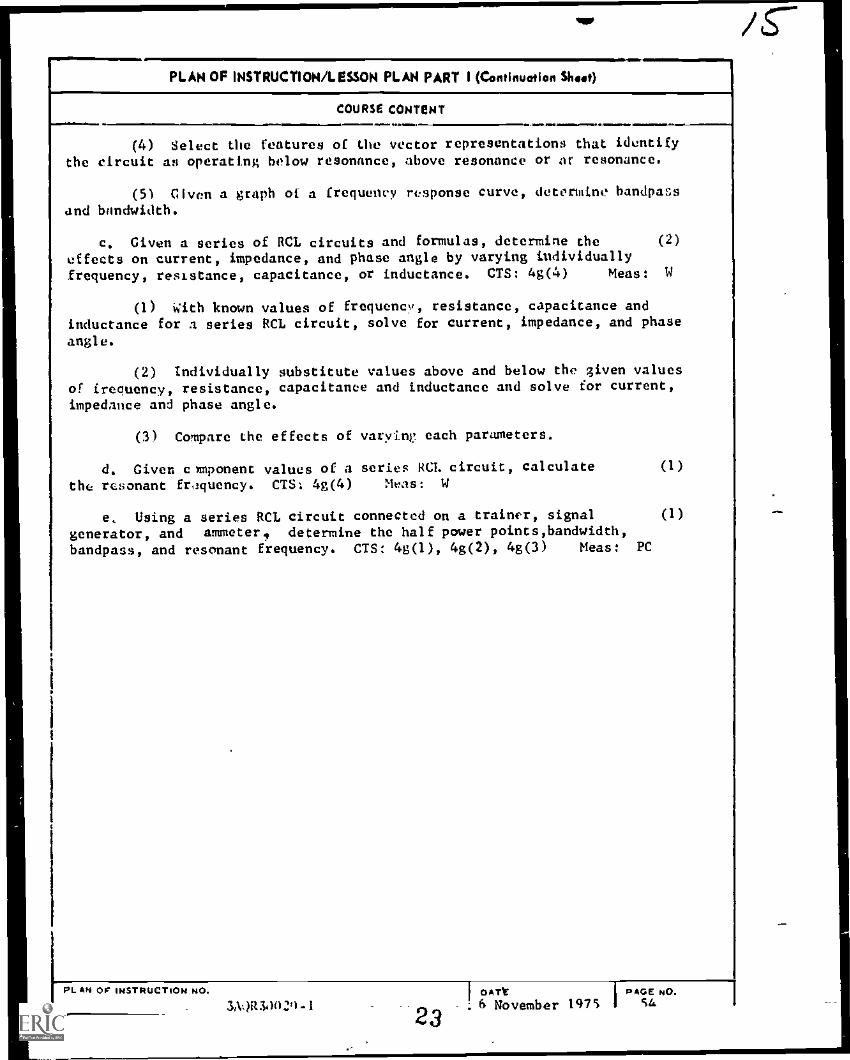
(4) Select the features of the vector representations that identifythe circuit as operating below resonance, above resonance or at resonance.
(5) Given a graph of a frequency response curve, determine bandpassand bandwidth.
c. Given a series of RCL circuits and formulas, determine the (2)
effects on current, impedance, and phase angle by varying individuallyfrequency, resistance, capacitance, or inductance. CTS: 4g(4) Meas: W
(1) with known values of frequency, resistance, capacitance andinductance for a series RCL circuit, solve for current, impedance, and phase
angle.
(2) individually substitute values above and below the given valuesof frequency, resistance, capacitance and inductance and solve for current,impedance and phase angle.
(3) Compare the effects of varying each parameters.
d. Given cmponent values of a series RCL circuit, calculate (1)
the resonant frequency. CTS. 4g(4) Meas: W
e, Using a series RCL circuit connected on a trainer, signalgenerator, and ammeter, determine the half power points,bandwidth,
bandpass, and resonant frequency. CTS: 4g(1), 4g(2), 4g(3) Meas: PC
(1)
PL AN OF INSTRUCTION NO.
3,1:)1134)(i21)..1 2} OATt I PAGE NO..6 November '1475 iá
I
PLAN OF INSTRUCTION/LESSON PLAN PART I (Continuation Shoot)
COURSE CONTENT. $ao r or or...L=0N oar.. rterw w am
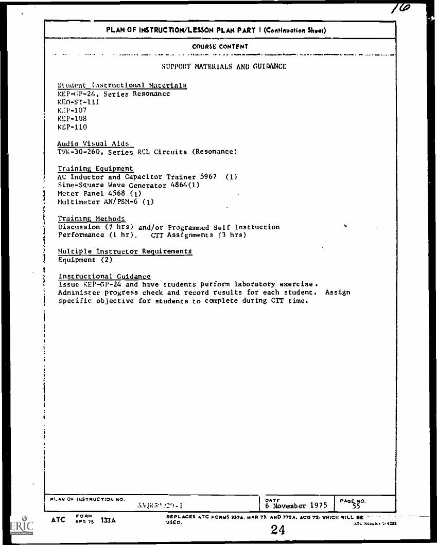
SUPPORT MATERIALS AND GUIDANCE
Student instructional Materials,KEP- (P -24, Series Resonance
KEO-ST-IIIKP-107KEP-108KEP-110
Audio Visual AidsTVK-30-260, Series RCL Circuits (Resonance)
Training EquipmentAC Inductor and Capacitor Trainer 5967 (1)
Sine-Square Wave Generator 4864(1)Meter Panel 4568 (1)Multimeter AN/PSM-6 (1)
Training MethodsDiscussion (7 hrs) and/or Programmed Self InstructionPerformance (1 hr), CTT Assignments (3 hrs)
Multiple Instructor RequirementsEquipment (2)
Instructional GuidanceIssue KEP-GP-24 and have students perform laboratory exercise.Administer progress check and record results for each student. Assignspecific objective for students to complete during CTT time.
PLAN OF INSTRUCT:ON NO.
IFORM
ATC APR 75 131A
3.1qR3*, ?'t -IDATr PAGE NO.6 November 1975 55
REAL ACES ATC FORMS 337A. AI AR 73. AND 770A, AUG 72, WMCIt WILL DEUSED. ATC ho.1.44 r t.-4292
24

10,1111M11111.
PLAN OF INSTRUCTION/LESSON PLAN PART I1......m.wwwww = VPRO...MAM... pNAME 'II IN4tOttel I0101 r lime.' III Lt.
14' o c 411.0411t. N itLrN. V...1 1.1 V $:
lit ii RCL Circuits
Electronic Principlesa t.. 4.0 re maba..aaamramr.
COURSE CONTENT-...- Ass. ....1 .64 M.
7, Parallel Resonance (Module 251
DURATION(Mews)
a. Given the response curves or parallel RCL circuits,compare the magnitude of current now it resonance and off resonanceCTS: 44g(4) Meas: EJ
(1) With given applied 'renuencs and component values ofa parallel RCA, circuit, determine it the circuit is capacitive,inductive or resistive.
(2) Calculate the resonant fr(qm.ncy
(3) Compare magnitude of curlew. ,1 t. r.:sonance and offresonance
Given a pa-allei circle l! 11,1
determine the efteets or current, imptaanee, and phase angle byindividually varying frequency, resistance, capacitance andinductance. CTS: 4;4(4) Meis: W
(l) With giver component values of a parallel RCL circuit,calculate he resonant frequency and draw vector representationsof curren: and voltage.
(2; Ansume ..ralues that wilt JU,;(' the circuit to operatebelow resonance. ?lot the vectOrs
(3) Assume values that will cause the ,ircuit to operateaboe? resonance. Plot du. vectors
.(4) Select the learore,5 vector representationsth; the circuit as op.:ratine at resonance, abovere!l-rance or oelow resonance.
(51 Civen a graph of a frequency response curve, determinethe bandpass and bancwidth
(4)
!UPERVISOR APPROVAL0 ATE
OF LESSON PLAN (PERT II)4SIGNATURE SIGNATURE
r--
PL AN .t" ...,TolitiCTiON NO.
DATE
nAtr PAGE
16 November 1975 57
ATC `ca"" 133 ,T. kev.:otREF, s T.: vpM I. MAR 73. AND 79":1, ALIG 72. WHICH WILL SEI 0. t.SeCAPO is
25 REST COrY

PLAN OF INSTRUCTION/LESSON PLAN PART I (Conliquation Shoe)
COURSE CONTENT11100...11MINANIIN. mk.a1.1.111=1/1.
c, given component values of a parallel RCL circuitcalculate the resonant frequency. CTS: 4ala Meas: W
(1)
d, Using a parallel RCL circuit connected on a trainer, (1)signal generator, and multimeter, determine the bandwidth,bundpass, half power points, and resonant frequency.CTS! 4x1.0A. tlaf2,1, !tan Meas: PC
8. Measurement and Critique (Part 2 of 3 Parts)
a. Measurement test
b. Test critique
SUPPORT MATERIALS AND CUIDANCE
Student Instructional MaterialsKEP-CP-25, Parallel ResonanceKEP-ST-1 TT
<EP -107
KEO-L08':EP -110
Audio Visual AidsTVK 30-264, Parallel KM Circuits (Resonance)
Iraininv Equi2ment.V Inductor ond Capacitor Itainer 5967 11)ine-Snuare ''eve Certeratt.r 4864 11)
AN;PSM6 (1)
Trainiry methods......-
Diseussinn hrs) and/or Programmed Seli instructionPqrformanre (i CTT Assignments (3 tars)
40 Ai,
Multiple instructor geonirementttquipment
1
Instructional guidanceTssue KEP-CP-25 and have students perform laboratory exercise. Administerprogress check and record results for each student. Assign specific objectivesto be completed during CTT time. Inform students that a measurement test musthe taken covering modules 24 and 25.
PLAN Ai :NSTRUCTION NO.'AC100020-1
Ne
4,41 COf
26oATE CPA6E
6 November 1975 58NO

PLAN OF INSTRUCTION /LESSON PLAN PART I
NAPZ ilc ,NSTNUC TOO
.. . . .. 0 A. .4..BLOC 04 Nt.MGC II , ill.66A i-tit c
litI
RCL Circuits
LOUOISE TITi.£
Firctronic Principles
COURSE CONTENT 2DURATION
(Howe)». ............
9. Tim (;ostants (Nodule 26)
a. riven a DC seriet: RC circuit, specified time componentvalues, and a Universal Time Constant Chart, determine the percentof charge on a capacitor; the percent of discharge of a capacitor.CTS: 4i Meas: W
(1) Relate the following terms to time:
(a) Transient
(b) Transient response
(c) Transient voltage
(d) Transient .current
(e) Transient interval
(2) Effects of component value* on transient response.1
:
i
(3) Define time constant in terms of RC and RL.
1
I y.) Explain Universal Time Constant Chart in terms of RC1 .1:.,1 r% t.rcuits.
i
:. (aw.% a PC series RL circuit, specified time, component. ':, awl 4 0.!niversa1 Time nen.stant Chart, determine the percent
of c-:r-cat )11ite-up, the percent of current decay. CTS: 4i
!
'I
12
(9/3)
(2)
(2)
SUPERVISOR APPROVAL OF LESSON PLAN (PART II)SIGNATURE i
1---b AT C SIGNATURE DATE
«.......... -II!$I$
I 1
1.----- Ai PL AN ::: .,, I qu:T;Os4 NO.
1.A:.;1.310/()-1
DATE
6 November 1975PAGE NO.59
ATC :CAM.3.5ct /5 133 AT! K. e .:et ....2 NEPLAt..7.S ATC f Off MS 337. MAR 73, AND 770, AUG 72, WHICH W144 et
USED.
BEST C1PY Al!' !1:27

ce:1PLAN OF INSTRUCTION/LESSON PLAN PART I (Continuation Shoot)
COURSE CONTENT1.111 411.0.
(1) RC circuit characteristics,
(a) Identify clorve on Universal Time Constant C1I4rt that showspercent of charge and discharge of a capacitor in a DC series circuit.
(b) Use a DC series RC circuit and Universal Time Constant Chartto determine
1 EC and ER when En, R, C, and time am known.
2 number of time constants when Ea, Ect R, and C are known.
3 R when Ea, C, EC,, and t are known.
4 I when Ea, to C and R are known.
5 C when ER, t, Ec, and R are known.
6 Ea when ER, t, R, and C are known.
c. Given series RC and RL circuits with component values and (2)formulas, compute the time constant for each. CTS: 4i Meas: W
d. Given uaveshapes of long, medium and short time constants (2)
of RC and RL circuitstidentify Ecp ER, and EL with the correct waveform.CTS: 4i Meas: W
(1) Relate long, medium, and short TC to integrated and differentiatedwaveforms.
(2 Idntify voltage waveforms developed across resistor and capacitorin RC long, medium, and short TC networks.
(3) Identify voltage waveforms developed across resistor and coil inRL long, medium, and short TC networks.
e. Given a trainer containing series RC or RL networks, (1)
oscilloscope, specified square wave frequelcy and voltage, identifythe output wave as either differentiated or integrated. CTS: 4i Meas: PC
Pt AN OF INSTRUCTION NO.3.VIR3:1n2n- 11
I DAT? I oAGE %O.28 6 November 1975 1 60

=1=..PLAN OF INSTRUCTION/LESSON PLAN PART I
4&4411 tti Noir Hut: on
40, .. . .4+
01.1 hk.h/81:01 14.0Cli
lit j RCL Circuits
OUNSR
Electronic Principles
1 COURSE CONTENT
9, Tir.t rAnstantn (Module 26)
11...M,
DURATION2
(Hour.)
a, Civrm a DC serla:: RC circuit, specified time componentvalues, and 4 Universal Time Constant Chart, determine the percentof charge on a capacitor; the percent of discharge of a capacitor.CTS: 4i Meas: W
(1) Relate the following terms to time
(a) Transient
(b) Transient response
(c) Transient voltage
(d) lranslent current
(e) Transient interval
(2) Effects of component values on transient response,
(3) Define time constant in terms of RC and RI..
Explain Universal Time Constant Chart in terms of Re
(:iveh a DC series RL cireta, specified time, componenttad a !:nlversal Time rstant Chart, determine the percent
ai e-:: -cat th' prcent of current decay, CTS: 4i"0.1r. .4
12
(9/3)
(2)
(2)
UPF.RVISOR APPROVAL OF LESSON PLAN (PART II)SIGNATURE DATE SIGNATURE DATE
) pL 4l riv:TION NO. OATS
6 November 1975PAGE NO.
59
REP4ALESATC 1.01:445337. NAN 73. AND 770. AUG 72. WHICH WILL BEATC 'CAM 133 Al?, "4"'''' 29 USED.AA'R /S 29BEST COPY AVNIAILE

PLAN OF INSTRUCTION/LESSON PLAN PART I (Continuation Slwat)
Iimprre
COURSE CONTENT...1==i
(1) RC circuit characteristics.
(a) Identify ct!rve on Universal Time Constant C1Art that showspercent of charge and discharge of a capacitor in a DC series NJ: circuit.
(b) Use a DC series RC circuit and Universal Time Constant Chartto determine
1 Ec and ER when E4, R, C, and time am known.
2 number of time constants when Ea, Ec, ., and C are known.
3 R when Ea, C, Ec, and t are known.
4 I when Ea, t, C and R are known.
5 C when ER, t, Ec, and R are known.
6 Ea when ER, t, R, and C are knovn.
c. Given series RC and RL circuits with component values and (2)
formulas, compute the time constant for each. CTS: 4i Meas: W
d. Given waveshapts of long, medium and short time constants (2)
of RC and RL circuits,identify EC, ER, and EL with the correct waveform.Cnt: 41 Mea5: W
(1) Relate long, medium, and short TC to integrated and differentiated
waveforms.
(2) Identify voltage waveforms developed acrois resistor and capacitorin RC long, medium, and short TC networks.
(3) identify voltage waveforms developed across resistor and coil inRL long, medium, and short TC networks.
e. Given a trainer containing series RC or RL networks, (1)
oscilloscope, specified square wave frequency and voltage, identifythe output wave as either differentiated or integrated. CTS: 4i Meas: PC
PLAN OF INSTRUCTION NO.3:111R3nli2,- I 30
IDATF I PAGE NO6 November 1975 1 60

PLAN OF INSTRUCTION/LESSON PLAN PART I (Continuation Shoot)
p . -
COURSE CONTENT. . . - - . - , . *M. ...../MMAY.A1 40
SUPPORT MATERIALS AND CUIDANCE
Student Instructional MaterialsKEP-OP-26, Time ConstantsKEP-ST-IIIKEP-107KEP-108KEP -807, Universal Time Constant Chart
Audio Visual AidsTVK-30-851, RC TransientsTYK -30 -852, RL Transients & Wave Shaping
Training EquipmentAC Inductor and Capacitor Trainer 5967 (1)Sine-Square Wave Generator 4864 (1)Oscilloscope A/USL-.941)Isolation Transformer 5124 (1)
Training MethodsDiscussion (8 hrs) and/or Programmed Self InstructionPerformance (1 hr)CTT Assignments (3 hrs)
Multiple Instructor RequirementsLquipment (2)
Instructions' GuidanceIssue.:;EP-GP-26, Time Constants and nave students perforT laboratory exercise.A-iminizter proEress cneck and record results of each student. Assignspecific oLjectives to Le completed during CTT time.
PLAN OF INSTRUCTION NO.
FORMATC ,0 74 133A
OATS PAGE NO.3AnR7121-1 6 November 1975 61
REPLACES ATC FORMS 337A, MAR 73. AND 770A. AVG 72. VONCH 00LI. SC'moos ro ..... ...... %.4,4,
3 1

HAM( or ntle rOci
41 e N11M4F n
111.
1
PLAN OF INSTRUCTION /LESSON PLAN PART I
41(1t M ))11
RCL Circuits
COURSE CONTENT
1.1111111L
10. litters (Moduli, 27)
1-
ioulepitymt
.Electronic Principles- . ..... ,. ...........
mar 4111
a. From a list oi statements concerning filters, select theone that explains the low pass filtering action of a T sectiont aPi-section. CTS: 41 teas; 11
(1) Explain action of a mnw pr,s filter utilizing a
(n) A.-section filter
(b) '1- section filter
(c) Pi-section filter
b. From 4 t of statements concerning filters, select the onethat eIpinins high pass filtering action of a T seetion; a Pi-section.CV: 41 Mc a
(1) ENp1a;r1 action of a high ptss filter utilizing a
(a) L section filter
(b) ;- section filter4
(c) Pi-section filter
r.)771 a Lit ;:atementa concerning filters, select the oneth:t cx.)ains the h:1ivIa:-3 filterinp action of a parallel resonant
a series-pPralet circuit; a series resonant circuit.Aels: I.
1 11 ..xn141%! action of a bandpass inter utilizing a
(a 1 paralkl re.Awnant ciecuit
(b) series resonant Ciro-Mkt,MI. 44, 11A
SION ATUPE_-______
ALAN 1NS C44jeT.ON NO
DURATION(Noah)
6
(4/2)
SUPERVSSOR APPROVAL OF LESSON PLAN (PART II)DATE SIGNATURE+1 .. =1 ....1MM,M DATE
GATE6 November 1975
PAGE NO.63
ATC F eIRMAPT 7S 133 uwo.NE1.4.CE$ FMS 337. MAP 73. ANC 770. AUG 72, VonEm vnt.t. BE
32 BEST COPY AVAIANif

.QCPLAN OP INSTRUCTION/LESSON PLAN PART I (Continuation Shoot)
COURSE CONTENT
(c) Series-parallel arrangement of a series and parallel resonantcircuit
d. From a list of statements concerning filters, select Of. one thatexplains the bard reject filtering action of a parallel resonant circuit; aseries-parallel circuit; a series resonant circuit. CTS: 4j Meas: W
circuit
(1) Explain action of a bandpass filter utilizing a
(a) Parallel resonant cireui.
(b) series resonant circuit
(c) series-parallel arrangement of a series and parallel resonant
SUPPORT MATERIALS AND GUIDANCE
Student Instructional MaterialsKEP-GP-27, FiltersKEP-ST-IIIKEP-107KEP-110
Audio Visual AidsTVK-30-305, Filters ATVK-30-306, Filters B
Training Mvthodr.Discussion (4 hrs) and/or Programmed Self InstructionCTT Assignments (2 hrs)
Instructional GuidanceIssue KEP -GP -27 and assign specific objectives to be completed during CTT time.
PLAN OF INSTRUCTION NO.
3A0R30(01-1GAT_ PAGE
6NO.6 November 19751 4
...
PLAN OF INSTRUCTION/LESSON PLAN PART I
NAMI. cat oet r Nur tr. COuli*JE TITLE
Electronic PrinciplesBLOCK Nutmeg T-W.00K TITLE
111. KCL Circuits
I COURSE CONTENT x DURATIONMow.)
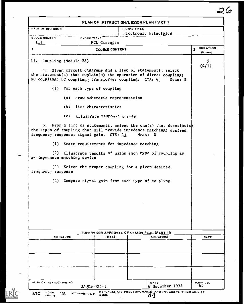
11. Coupling (Module 28)
a. Given circuit diagrams and a list of statements, selectthe statement(s) that explain(s) the operation of direct coupling;RC coupling; LC coupling; transformer coupling. CTS: 4j Meas: W
(1) For each type of coupling
(a) draw schematic representation
(b) list characteristics
(c) illustrate response curves
b. From a 1:st of statements, select the one(s) that describe(sithe types of coupling that will provide impedance matching; desiredfrequency response; signal gain. CTS: a Meas: W
(1) State requirements for impedance matching
(2) Illustrate results of using each type of coupling asan impedance matching device
(2) Select the proper coupling for a given desiredfrequenc, response
(4) Compare signal gain from each type of coupling
5
(4/1)
SUPERVISOR APPROVAL OF LESSON PLAN (PART II)SIGNATURE DATE SIGNATURE DATE
I
I
el. /4.4 Oi"tivriRUCTtON NO.3 AQW50121-1
[ GATE16 November 1975
PAtte NG.65
ATC F'P" REPLACES ATC FORMS 7J7. wA10,3LAANG 770. AUG 72. WHICH wILL SEFR "s OSEO.

PLAN OF INSTRUCTION/LESSON PLAN PART I (Continuation Shoot)
COURSE CONTENT
eupmer mmnIAIL AND GUIDANCi.,
;A:tdent. Instructional MaterialsKEPGP-26, Coupling
KEP=107KEP-110
Audio Visual AidsTVK ::0..:089 Coupling
Traininr tiethodsDiscussion (4 hrs) and/or Programmed Self InstructionCTT Assignment (1 hr)
12. Measurement and Critique (Part ; of , Parts)
a. Measurement test
. Test critique
Instr4ctional GuidanceIssue r.:JLGP-28 and make specific assignments to be accomplished during CTT time.Inform students that a measurement test must be taken covering modules 26, 27and 28.
PLAN OF INSTRUCTION NO...;AQR50020-1
35OAT C
6 NovemGer 1975PAGE NO.
66

r
C
4
I
C
ATC ST 3AOR3X020-XPrepared by Koesler Trc
KEP ST /DIGEST 111
Technical Training
Electronic Principles (Modular Self-Paced)
Block III
DIGEST
ATC Kees ler 6.2460
1 April 1975
AIR TRAINING COMMAND
., 7- -7
Designed Fin ATC Course Use
D 0 Nor USE OH THE JO
36
,
Basic and Applied Electronics DepartmentKessler Air Force Base, Mississippi
# P
Student Text 3AQR3X020-XKEP-ST/DIGEST I-111
1 April 1975
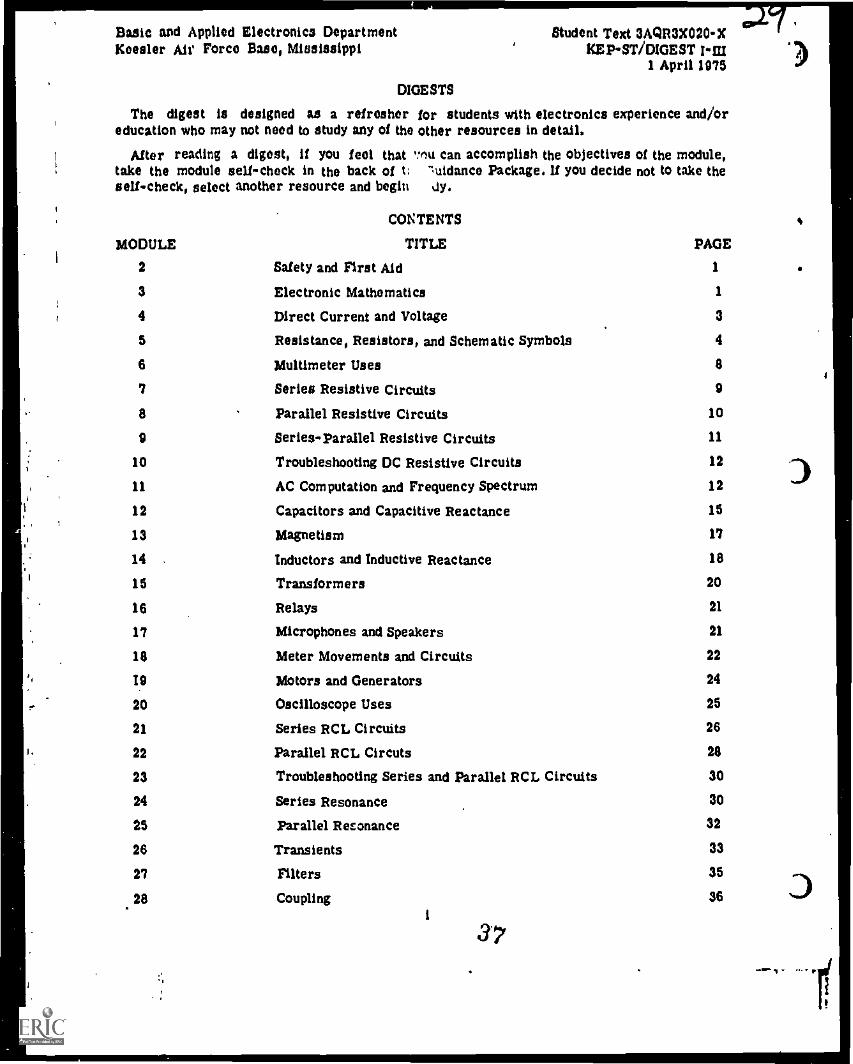
DIGESTS
The digest is designed as a refresher for students with electronics experience and/oreducation who may not need to study any of the other resources in detail.
After reading a digest, if you feel that imu can accomplish the objectives of the module,take the module self-check in the back of t: ".uidance Package. U you decide not to take theself-check, select another resource and begin ay.
CONTENTS
MODULE TITLE PAGE
2 Safety and First Aid 1
3 Electronic Mathematics 1
4 Direct Current and Voltage 3
5 Resistance, Resistors, and Schematic Symbols 4
6 Multimeter Uses 8
7 Series Resistive Circuits 9
8 Parallel Resistive Circuits 10
9 SeriesParallel Resistive Circuits 11
10 Troubleshooting DC Resistive Circuits 12
11 AC Computation and Frequency Spectrum 12
12 Capacitors and Capacitive Reactance 15
13 Magnetism 17
14 Inductors and Inductive Reactance 18
15 Transformers 20
16 Relays 21
17 Microphones and Speakers 21
18 Meter Movements and Circuits 22
19 Motors and Generators 24
20 Oscilloscope Uses 25
21 Series RCL Circuits 26
22 Parallel RCL Circuts 28
23 Troubleshooting Series and Parallel RCL Circuits 30
24 Series Resonance 30
25 Parallel Resonance 32
26 Transients 33
27 Filters 35
28 Coupling 36i
37. ..=. 1 ...
)
3
i
III
Ilr iereti ;ire used to concentrate theIlene WHIN. The pole pieces and th
anti ture core provide a Low reluctance pati
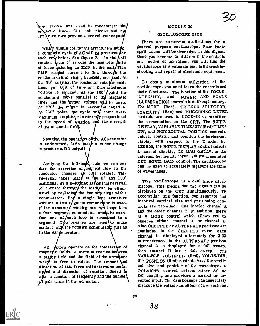
With single coil for the armature windi g,a comp to cycle of AC will be produced oreach re aution See figure 2. As the oilrotates om 0° it cuts the magnetic inesof force nducing an EMF in the coil ThisEMF eau es current to flow throu theconductor, slip rings, brushes, and ad. Atthe 000 po ition the conductor cuts e mostlines per it of time and thus aximumvoltage is i uced. At the 180° point theconductors m ve parallel to t magnetictines and the .utput voltage w 11 be zero.At 270° the o put is maxim m negative.At 360° point, e cycle wi start over.Maximum amplit e is direct proportionalto the speed of tation a d the strengthof the magnetic fief .
Now that the operatis understood, let'sto produce a DC output
Applying the left-hathat the direction ofconductor changesreversal takes placpositions. By a switof current througnated by replacincommutator. Fowinding a twoIf the armatura four segmeOne end ofsegment. Tcontact witin the AC
c
at tng act
the loadthe two sa single
gment commutwinding has twcommutator wou
each loop is conno brushes are usedthe rotating commutat
enerator.
the AC generatora minor change
rule we can seerent flow in the
1 rotates. This0° and 180°
on this reversalcan be elimi-
rings with ap armaturefor is used.
loops thenbe used.ted to ato make
just as
MI otors operate on the interact n ofmagne c fields. A force is exerted be eena sta., r field and the field of the arm urewhi is free to rotate. The amount ddir ction of this force will determine mo rsp ed and direction of rotation. Speeda o a function of frequency and the numbe
1 pole pairs in the AC motor.
MODULE 20
OSCILLOSCOPE USES
There are numerous applications for ageneral purpose oscilloscope. Four basicapplications will be described in this digest.Once you become familiar with the controlsand modes of operation, you will find theoscilloscope is a valuable tool in the trouble-shooting and repair of electronic equipment.
25
To obtain maximum utilization of theoscilloscope, you must learn the controls andtheir functions. The function of the FOCUS,INTENSITY, and POWER AND SCALEILLUMINATION controls is self-explanatory.The MODE (Red), TRIGGER SELECTOR,STABILITY (Red) and TRIGGERING LEVELcontrols are used to LOCK-IN or stabilizethe presentation on the CRT. The HORIZDISPLAY, VARIABLE TIME/DIV (Red) TIME/Drv, and HORIZONTAL POSITION controlsselect, control, and position the horizontaldisplay with respect to the X axis. Inaddition, the HORIZ DISPLAY control selectsa normal display, 5X MAG display, or anexternal horizontal input with its associatedEXT HORIZ GAIN control. The oscilloscopecan be used to accurately measure the timeof waveshapes.
This oscilloscope is a dual trace oscil-loscope. This means that two signals can bedisplayed on the CRT simultaneously. Toaccomplish this function, two separate andidentical vertical size and positioning con-trols are prov:Ied: One labeled channel Aand the other channel B. In addition, thereis a MODE control which allows you toobserve either channel A or channel B.Also CHOPPED or ALTERNATE positions areavailable. In the CHOPPED mode, eachchannel is displayed alternately for 3.33microseconds. In the ALTERNATE positionchannel A is displayed for a full sweep,then channel B for a full sweep. TheVARIABLE VOLTS/DIV (Red), VOLTS /DIV,the POSITION (Red) controls vary the verti-cal size and position of the waveshape. APOLARITY control selects either AC orDC coupling and provides a normal or in-verted input. The oscilloscope can accuratelymeasure the voltage amplitude of a waveshape
38

The oscilloscope is a very accurate pieceof test equipment and is widely used toobserve waveforms to insure their correctshape as indicated in technical orders andoperating instructions. Many problems ortroubles can be identified with theoscilloscope.
The oscilloscope can also compare thephase relationship between two signals. Withthe dual trace capability, two signals canbe compared by measuring the distancebetween the waves and multiplying by 360°provides the phase difference, expressed indegrees.
Another function of the oscilloscope is todetermine the frequency of a waveformthrough the accurate measurement of time.The oscilloscope allows you to set the timeit takes for the beam to travel 1 centimeteracross the CRT. Multiplying the time bythe number of centimeters in one cycle willgive the time of one cycle. The unknownfrequency can then be determined by usingthe formula; Frequency = 1/Time. Ofcourse, in the formula, time is the time forone cycle.
The last function of the oscilloscope isthat of measuring voltage. The oscilloscopeallows you to set the amount of voltageneeded to make the electron beam deflect 1centimeter in the vertical direction on theCRT. The AMPLITUDE CALIBRATORprovides an amplitude calibrated 1000 cyclesquare wave to calibrate the verticalchannelof the oscilloscope. By multiplying voltagefor 1 centimeter of deflection by the numberof centimeters between the positive peakand the negativ e peak will give the peak-to-peak amplitude of the waveform. Theeffective, average, and peak voltages of aSine wave can be easily calculated using thepeak-to-peak value. DC voltages can alsobe measured. Ground the input to the scopeto set up a reference. Now apply the DCvoltage and count the number of centimetersof deflection from the reference. Multiplythe centimeters of deflection by the settingof the VOLTS/DIV control to determine theamplitude of the DC voltage.
3/MODULE 21
SERIES RCL CIRCUITS
You have studied the individual effects ofresistance, inductance, and capacitance. Alloppose current flow. What is also veryimportant is that inductance and capacitanceintroduce a phase shift between current andvoltage. Resistance does not produce aphaseshift. In series RCL circuits it is importantto understand this phase shift. Vectors showthe phase relationships of current, voltage,resistance, and impedance (Z).
The following properties of a basic seriescircuit apply:
1. Current in any part of a series circuitis the same. There is only one current ina series circuit.
2. The vector sum of the voltage dropsaround a closed Loop equals the appliedvoltage.
3. The individual voltage drops can bedetermined by the use of Ohm's Law.
ER
= IR
EC = LICC
EL = IXL
Due to the current and voltage relation-ships across a capacitor and inductor, thephase relationship of XC and XL are exactlyopposite. As a consequence, XC and XLeach cancel the effect of the other. WhenXL and XC are in series, the net reactanceis the difference between the two seriesreactances. Three possible conditions existin such a circuit.
1. XC isEC greatercapacitive.
2. XL isEL greaterinductive.
26
39
greater than XL. This makesthan EL and the circuit acts
greater than XC. This makesthan EC and the circuit acts
ANL
J..

3. XL
equals X C. This condition iscalled resonance. This makes EC equal toEt, and the circuit acts resistive.
The first step in the solution of a seriesRCL circuit problem is to determine thereactance of the inductor and capacitor.Refer to figure 1 for a sample.
100 Hr90v --.159 IL,
x C k.na. = 10 k ohms
XL = 27r fl, = 20 k ohms
15k o
31.9 H
Figure 1 REP4 -1028
Next, we solve for total impedance (Zt)In this circuit by taking the vector sum.Remember that the reactances cancel sosubtract the smaller reactance from thelarger reactance.
Zt = AfR2 + (XL - x C) = 18 k ohms
Knowing the total impedance and the appliedvoltage, it is easy to determine the totalcurrent.
EI =a = 5 mAt Zt
Individual voltage drops can be determinedby using Ohm's Law.
EC = It XC
= 50V
EL = ItXL II 100 V
ER = I tRF"
75V
27
3-2-Vectors show the relationships between
resistance, capacitive reactance, andinductive reactance. Figure 2A shows thisrelationship using resistance as the reference.The angle theta (0) for Zt can be determinedby using the cosine function.
II 15 k ohmsCos 0 *Z-.....*
= .e333t 18 k ohms
Referring to the trigonometric tables, theangle is 33.6°.
& Xt. 20ko
w--- 2 181(0
aR 15ko
Xt 10k 11
A
EL 100V
E. 90V
/75V
*1/4 50v
B
REPO -2029
Figure 2
Using current for a reference, we can alsoplot the current and voltage vectors for thisproblem. See figure 2B. Ea has the sameangle as Zt, if It is used as a reference.Ea is used as the reference in voltagevector diagrams; therefore It will be at-33.7°. See figure 2C.
40

Co ils and capacitors store energy duringpart of the cycle and return it to the drcult during part of the cycle. Therefore,they dissipate no power. Because of thiswe have to differentiate between true power{Pt) and apparent power (Pa) in a seriesRCL circuit. True power can only be cal-culated for the resistor.
2 E2Pt = I R = R
0 IE R= 375 mW
There is no power dissipated in a purecapacitor or inductor. Although a reactancedraws current from the generator, E and Iare 90° out of phase. The circuit storesenergy in the electromagnetic field of theindUctor, and in the electrostatic field ofthe capacitor. For both cases, the storedenergy is returned to the circuit so that nopower is dissipated. The product of Eaand It then is considered apparent powerand is expressed in voltamperes (VA).
EPa = Ea It = it2Zt = 450 mVA
2
Power factor (PF) is a numerical ratioof true power to apparent power.
PF =Pa 375 mVA = .8333Pt 450 mW
Power factor can also be determined by:
PF uEER
=R = Cos 9
a Zt
The power factor is always equal to thecosine of angle theta and can never begreater than one. The closer to one, themore resistive the circuit; and the closerto zero, the more reactive the circuit.
28
MODULE 22
PARALLEL RCL CIRCUITS
Let us review the properties of a basicparallel RCL circuit.
1. The voltage across each branch of aparallel circuit is the same.
2. Total current is the vector sum of theindividual branch currents. Total currentwill be:
It &VIR2 + (IL
3. The current in each branch is givenby Ohm's Law.
EagsR R
Ea
IC X
Ea
IL XL
4. Due to the current and voltage relation-ships for a capacitor and inductor, the phaserelationship of IC and IL are exactly opposite.Total reactive current will be the differencebetween the capacitive current and the in-ductive current.
A basic parallel RCL circuit is shown infigure I. The first step in the solution ofthis parallel RCL problem is to determineXc and XL.
.159X
C= = 10 k Q
XL 21r fL = 40 k Q
41

TO V151 lit
Figure 1
143,4-1070
Using Ohm's Law, solve for lc (16 mA),IL (4 mA), and IR (5 mA).
tA1R2
4. (1C
- Id2 = 13 mA
Using total current and the applied voltage,solve for total impedance.
Zt 1 12.3 k
lc a 16 mA
1........ ,.,,, .............. ,...
st 4 mA
1
up
Figure 2
It :13 mA
I R '45 mA
3c/Figure 2 shows the relationship of the
current values. Angle 0 can be determinedby using the cosine function,
IR 5 m ACos 0 =,It 13 mA 2 3846
Referring to the trigonometric tables,find angle 0 to be 67.4°.
We say the circuit is acting capacitivelyif the capacitive current is larger than theinductive current. How the circuit acts isdetermined by which reactive componenthas the larger current.
As with series RCL circuits, there is noreal power dissipated by the capacitor orthe inductor in a parallel RCL circuit.Real or true power (Pt) is the power dissi-pated by the resistor. The unit of measureof Pt is the watt.
2E
. 2,P = IRE =
R= LI/ nt R R
Apparent power (Pa) is the product of Eaand It and is measured in volt amperes(VA).
2E 2Pa = I L E = a mikza t a t
In this circuit, Pa is 2.08 VA and Ptis 800 mW. Power factor (PF) is the ratioof true power to apparent power.
PFPt 800 mW .3846Pa 2.08 VA
Notice that the PF is the same as theCos of the phase angle (0).
When the applied voltage is not given,ReP4-1080 you can solve for total impedance by using
an assumed voltage. Use the assumed voltageand calculate the current through e ach branch.
29
4

Combine the branch currents to determinetotal current. Use total current and theassumed voltage to calculate total impedance.Regardless of what voltage is assumed, theimpedance will be correct because impedanceis the ratio of voltage to current.
MODULE 23
TROUBLESHOOTING SERIES ANDPARALLEL RCL CIRCUITS
Troubleshooting RCL circuits is verysimilar to the procedure used in trouble-shooting resistive circuits. However, it isimportant to know the type of indicationsreactive components present when trouble-shooting for opens and shorts.
Generally a capacitor can be checked withan ohmmeter. A good capacitor will presenta momentary deflection towards zero, thenthe indicator will return to infinity. Thisprocedure is normally used to check largecapacitors. With small capacitors it may bedifficult to detect this deflection so caremust be used. For small capacitors the bestcheck is to replace the capacitor with onethat is good. A shorted capacitor will indi-cate a low or zero resistance when checkedwith an ohmmeter. An open capacitor willgive an infinite reading on the ohmmeter.
In troubleshooting, we will also experiencetroubles with inductors, and as with capaci-tors, an ohmmeter can be used. Rememberthat when using the ohmmeter to check aninductor, you are measuring the DC resistanceof the wire. Regardless of the fact the wireis coiled, it is still a conductor and hasvery little resistance. When the ohmmeteris placed across a coil that is shorted, themeter will indicate 0 ohms. Care must betaken because coils with few turns will showa low resistance reading when they are good.When just a few turns of an inductor shorttogether, it is very difficult to check withan ohmmeter. In this case the best check isto substitute a known good inductor.
30
MODULE 24
SERIES RESONANCE
In the series RCL circuit, we know thatan increase in frequency will produce an in-crease in XL and a decrease in XC. Thefrequency at which XC = XL is called theresonant frequency and is designated by fr.See figure 1.
2B H
* Figure 1
fr = 300 Hz
Ea = 25 V
XL
= 53 k ohms
XC = 53 k ohms
REP4 -1121
Z = R (5k ohms)
For every combination of L and C, therewill be one frequency where XC = XL.The formula for determining this frequencyis fr = .159Nre. An important propertyof a series RCL circuit is that impedanceis low at resonance and increases rapidlyas frequency is increased or decreased.(Z is equal to R and It is maximum.)See figure 2.
I
43
f,
Figure 2
FREQUENCYREP4-:222

When the applied frequency is less thanthe resonant frequency, the circuit is capaci-tive. XC is greater than XL. When the appliedfrequency is greater than the resonant fre-quency, the circuit is inductive. XL isgreater than XC. Figure 2 shows the tworeactances as well as the total impedanceand total current as the frequency is variedfrom below to above resonance. Notice thatcircuit impedance is minimum and circuitcurrent is maximum at resonance.
The Q of a series resonant circuit isdefined as the ratio of the inductive reactanceof the circuit to the resistance of the circuit.The Q of the coil is defined as the ratio ofXL of the coil to the resistance of the coil(Q = XL/R). if a series circuit has only onecoil, and the resistance of the circuit is theresistance of the coil, then Q of the circuitand Q of the coil are one and the same. Coilswith a Q of 10 or more are said to be highQ coils.
Varying the resistance will not affectresonant frequency but will affect circuit cur-rent by affecting Q. Figure 3 shows the effectof changing resistance in a series RCLcircuit. Curve A shows the variation in cur-rent as the frequency increases from belowresonance to above resonance. Note that curveA comes to a much sharper peak than do theother curves. Since in all cases XL has
,..re
1
1
1
.
351
3remained fixed, the Q is greater when theresistance is smaller. The current-frequencyresonance curve in a high Q circuit risesto a sharp peak at the resonant frequencyand the peak of the curve for lower Qcircuit is broader.
In many series RCL circuits, a largenumber of frequencies may be supplied tothe circuit. The current that would meet theleast opposition would be that generated atthe resonant frequency. We say that the cir-cuit passes the resonant frequency. if it isdesired to pass current at a particular fre-quency, the capacitance or inductance (orboth ) may be varied so that XC = XL atthe desired frequency. This is called tuningthe circuit. A series RCL circuit is said tobe tuned to a given frequency when thecapacitance or inductance (or both) have beenadjusted so the given frequency becomes theresonant frequency. It can be seen in figure3 that a high Q circuit is more selective ormore sharply tuned since the current at theresonant frequency is much greater than thecurrent slightly off-resonance.
U frequencies (other than the resonantfrequency) are passed at a lesser magnitudethan the resonant frequency, between whatfrequencies is a significant amount of currentpassed? Unless we know what we mean by asignificant amount, we cannot answer the
i
1
I
1
I
355
i
CURVE AR = i012
z
1
i
L360
FREQUENCY
Figure 3
31
44
CURVE BR = 21 0
CURVE CR = 30 0
kHz
REPO -.1123

question. The significant amount is morethan .707 times !max. The .707 points onthe current-frequency curve (see figure 3)are called the half power points. The halfpower points on curve A are Y and Z.Drawing a line down from point Y is 350kHz and from point Z is 360 kHz. Thebandwidth is defined as the difference betweenthe upper half power point frequency and thelower half power point frequency. (BW = 360kHz - 350 kHz v 10 kHz).
The half power points of curve B are Wand X. The bandpass in this case is greaterthan curve A, and the bandwidth is wider.The bandwidth of curve C is wider thaneither that of A or B. If a series circuitis resonant at a given frequency, increasingR increases the bandpass and decreasesselectivity.
When the resonant frequency, fr and theQ are known, bandwidth may be found by theformula BW = fr/Q.
MODULE 25
PARALLEL RESONANCE
A large number of electronic devices con-tain parallel resonant circuits. The circuitdiagram of figure 1 represents a typicalparallel resonant circuit. The resistor maybe the resistance of the coil.
41
Figure 1
REP4-1148
32
In parallel RCL circuits, resonance occurswhen the frequency causes IC to equal IL.This frequency can be determined by theformula fr
In figure 1, there are two paths in whichcurrent may flow: One through the coil andthe other through the capacitor. U the gene-rator is operating below resonance, most ofthe current will flow in the inductive branch,since at low frequencies XL is less thanXC. The circuit acts inductively. If the gene-rator is operating above resonance, most ofthe current will flow in the capacitive branch,since XC is now lower than XL-The circuitis acting capacitively. Between these twopoints there is the resonantfrequency, wherethe inductive current equals the capacitivecurrent. At this point lc and IL being equal,but 180° out of phase, cancel each other andthe circuit is purely resistive. Total linecurrent is then a result of the resistor andis quite small. At resonance, line currentis minimum, circuit impedance is maximum,and the phase angle is zero. See figure 2.
FREQUENCYI,
FREQUENCY
Figure 2 REP4 -1149
45
Figure 3
REP4-1150

Varying either frequency, capacitance, orinductance will cause the line current to in-crease while circuit impedance decreases.Varying the resistance will not effectresonance, but will effect the Q, therebycausing a change in bandwidth. (Qand bandwidth = frig.)
The three-branch parallel resonant circuitdiffers slightly from the two-branch cir-cuit when calculating Q, Because of theseparate path for current through the parallelresistor, figure 3, the formula for deter-mining the quality of the circuit is Q= R/XL.Therefore,
fr x XLbandwidth = a
MODULE 26
TRANSIENTS
Transients play a very important part inelectronic circuits, and for this reason theyshould be thoroughly understood. Transientvoltages and currents come into being as aresult of the application, change, or removalof a voltage from an electrical circuit.These can be divided into RC and RLtransients.
The RC transient begins with the appli-cation of a voltage to a series RC circuit.See figure 1. At first, all the appliedvoltage appears across the resistor. In time,
Figure I
REP4-1142
3E(as the capacitor becomes charged, the volt-age drop across the capacitor increases atthe expense of the voltage drop across theresistor. The transient comes to an endwhen the capacitor is charged to the appliedvoltage. Capacitor voltage opposes the appliedvoltage and reduces circuit current andresistor voltage to zero.
The duration of the transient intervaldepends on the value of R times C. Theproduct of R in ohms times C in faradsis the time constant (TC) in seconds. Inone time constant, the capacitor charges to63% of the applied voltage. For all intentsand purposes, the capacitor will be fullycharged after five time constants. See figure2. Using the Universal Time Constant Chart,
and the formula # TC = the percentageR C
of charge or discharge of a capacitor canbe calculated for any given time. With thisinformation, EC, ER, and the circuit currentcan be determined.
A second transient occurs whenthe appliedvoltage is removed and the capacitor isallowed to discharge.
The RL transient begins when a voltage issuddenly applied to a series RL circuit.
MO
33
$1
111111111111111111111111ME=Ziiimmuni1111111111..1111111111,2:4011111.1MME1,1111111111111111111n11111111111111111W1d110111111111211MMINIIIIMMIIIIIMIII1111111111PEIMIN 1111111111111KNIEMM:=21==1::1111111111,111IIIIIMMENIIIiiiiiMINi1111111MIMMI1111E1101.1.1111111/11MUMII11irrimiliscli
11,111111WEI
'
'
Orr .4te "kW° rAMILTAVZ...,...0.segasatwo
*moo. .a.r.ce b.ge<-=.51r
re.,,Tftritur OfoigLarn v loCt O.
«maw va.r.se c.----...."-Ir4111111111Mg.111111111,11111111101111Ii11111111.011VIIIIMME1111f111111111111 105111JIM15111111iniZr.211FRIM
fi 1
Volt.. tort tto.rovet1010.1.. 6111001.1$L NOVI; P. IC Mel. 06.0Jote
Figure 2. Universal Time Constant Chart
46
REP4 -2194
Figure 3
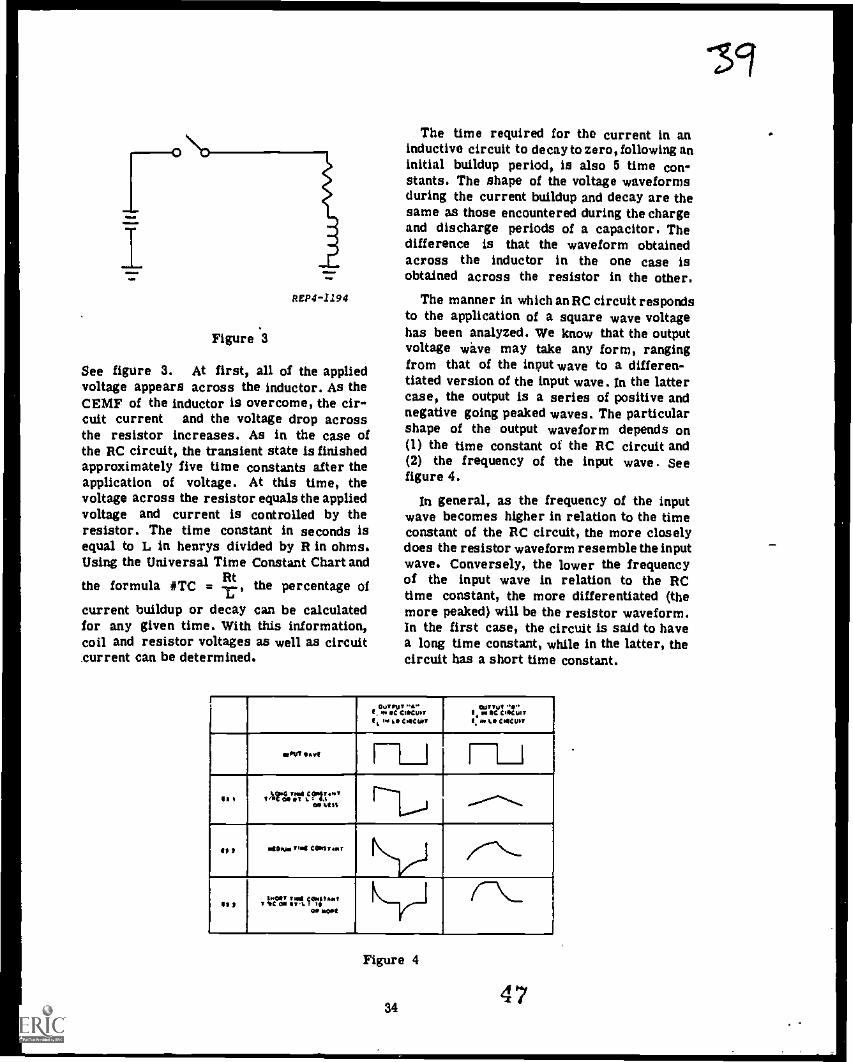
See figure 3. At first, all of the appliedvoltage appears across the inductor. As theCEMF of the inductor is overcome, the cir-cuit current and the voltage drop acrossthe resistor increases. As in the case ofthe RC circuit, the transient state is finishedapproximately five time constants after theapplication of voltage. At this time, thevoltage across the resistor equals the appliedvoltage and current is controlled by theresistor. The time constant in seconds isequal to L in henrys divided by R in ohms.Using the Universal Time Constant Chart and
Rtthe formula #TC =i
the percentage of
current buildup or decay can be calculatedfor any given time. With this information,coil and resistor voltages as well as circuitCurrent can be determined.
The time required for the current in aninductive circuit to decay to zero, following aninitial buildup period, is also 5 time con-stants. The shape of the voltage waveformsduring the current buildup and decay are thesame as those encountered during the chargeand discharge periods of a capacitor. Thedifference is that the waveform obtainedacross the inductor in the one case isobtained across the resistor in the other.
The manner in which anRC Circuit respondsto the application of a square wave voltagehas been analyzed. We know that the outputvoltage wave may take any form, rangingfrom that of the input wave to a differen-tiated version of the input wave. In the lattercase, the output is a series of positive andnegative going peaked waves. The particularshape of the output waveform depends on(1) the time constant of the RC circuit and(2) the frequency of the input wave. Seefigure 4.
In general, as the frequency of the inputwave becomes higher in relation to the timeconstant of the RC circuit, the more closelydoes the resistor waveform resemble the inputwave. Conversely, the lower the frequencyof the input wave in relation to the RCtime constant, the more differentiated (themore peaked) will be the resistor waveform.In the first case, the circuit is said to havea long time Constant, while in the latter, thecircuit has a short time constant.
1 OUTPUTI N4 OC Cleansto ..* fie CMCW,
OUTTO ..0.li. 0 K COMO/II, to %It CMCLes
OV, rt11____I
It I t "ficnowe i ?Z."PI at St 1-'1.0j .................*"...
ft 1 et Myr Mt Carivar
II I / r e : : i ritl III 6 "0* 1101!
_
Ly-ile--
Figure 4
3447
19

The transient behavior of an RL circuith analogous to that of an RC circuit. Inthe lit! circuit, the capacitor vole buildsup exponentially with time, while in the nL,circuit the current builds up exponentially.The time required for the voltage in theone case, and for current in the other, tobuild up to 83% of its final Value is onetime constant. In the latter circuit the time
Lconstant is L.
Rand RC are both measured
Rin seconds. For this reason, the UniversalTime Constant Chart is as useful in thesolution of RI, circuits as it is in thesolution of RC circuits.
The terms SHORT and LONG time con-stants have the same meaning with respectto RL circuits that they do with respect toRC circuits. Accordingly, the waveformsfrom across the inductor in the RL circuitis equivalent to the waveform obtained acrossthe resistor in the RC circuit. Similarlythe voltage waveform obtained across theresistor of the RL circuit is identical tothe waveform obtained across the capacitorin the RC circuit.
MODULE 27
FILTERS
A filter circuit consists of a combinationof capacitors, inductors, and resistors con-nected so that they separate unwanted fre-quencies from desired frequencies. In addi-tion, they can separate an AC signal froma DC signal. These components, and or com-bination of components, are arranged inbasicpatterns or sections (identifiable as an "L"section, "T" section, and "Pi" section)to accomplish filtering action. Filter circuitsmay range from very simple to very com-plex. Regardless of how simple or complexa filter circuit may be its basic actiondepends on the opposition each of its com-ponents presents to either alternating cur-rent or direct current.
Opposition presented to alternating cur-rent by a circuit containing inductance andresistance will increase as frequency in-
35
#creases due to the inductive reactance of theinductor. However, when DC is applied, theinductor presents an opposition for only ashort time (CEMF). After the CEMF is over-come, the only opposition to direct currentis the resistor.
The opposition to alternating currentoffered by capacitance decreases with an in-crease in frequency due to capacitivereactance. However, when DC is applied,the capacitor offers infinite opposition afterthe capacitor has charged.
A series resonant circuit offers littleopposition to frequencies within the resonantband. This circuit will offer more opposi-tion to other frequencies.
A parallel resonant circuit offers a greatdeal of opposition to frequencies within theresonant band, while offering very littleopposition to other frequencies.
Filters are identified by their action.There are four basic types.
Low Pass Filter. This filter will develop,in an output, all frequencies below the cut-off frequency. Frequencies above the cutoffwill be attenuated to an unusable Level.Proper selection and arrangement of com-ponents establishes the cutoff frequency.
High Pass Filter. This filter will develop,in an output, all frequencies above the cut-off frequency. Frequencies below the cutoffwill be reduced to an unusable level. Properselection and arrangement of componentsestablishes the cutoff frequency.
Band Pass Filter. This filter uses resonantcircuits. This filter, when properly arranged,will develop the resonant band in an output.All other frequencies will be reduced to anunusable level.
Band Reject Filter. The band reject filteralso uses resonant circuits. However, thisfilter will reduce the resonant band to anunusable level in the output. All other fre-quencies will be developed and allowed topass to the next circuit.
48

In conclusion, a filter circuit consists of acombination of capacitors, inductors, andresistors connected so they will either permitor reject the passage of frequencies or bandsof frequencies.
10v
PEAK 10Kn0
INPUT OUTPUT
R1 1g15 MI 41
20v R2
MODULE 28 I. 10Kn
COUPLING :COUPLING is defined as a means by which
signals are transferred from one circuit toanother. Two circuits are said to be coupledwhen they have a common impedance thatpermits the transfer of electrical energy fromone circuit to another. This commonimpedance, called a coupling element, maybea conductor, an inductor, a capacitor, atransformer, or a combination of two or moreof these components. Coupling circuitsusually, though not always, perform somefiltering action in addition to providing ameans of transferring electrical energyfromone circuit to another. The choice of nameis determined by the function of the circuitthat is of greatest importance. Basically,four types of circuits are used for coupling:the directiy coupled circuit, the capacitive-resistive coupled circuit, the capacitive-inductive type, and the transformer coupledcircuit. Each circuit has its own advantagesand disadvantages.
Direct coupling uses a conductor and/or aresistor to connect two circuits together, andprovides a direct path for signal currents.See figures IA and 1B. This type of couplingprovides reproduction of the exact signalat the output of the coupling circuit as itappeared in the input. It also allows the DCvoltage to be felt at the output of the couplingcircuit. In figure 1B, the output will be some-what lower than the input due to loadingeffect of the resistor. Direct coupling operatesover a wide frequency range.
Resistive-capacitive (RC) coupling is usedwhen the DC must be blocked and only theAC component passed to the output. Thecapacitor, with its basic action, blocks theDC and allows the AC component to bedeveloped across the resistor. See figure 2.
10vPEAK
A
10v RIPEAK i11 10Kn
DIRECTCOUPLING
INPUT OUTPUT
20v---- R2
110K
Pa
20 VOC
36 49
B
ECTCOUPLING
Figure 1
REP4 -356
COUPLINGCIRCUIT
15V10
0r- - --1RI
10K I
I
RC t
COUPLING II Cl
I1 1
R2 I I10K n I R3 t
I
1
1,...__ ..1
.
Figure 2
la
REP4 -357
e/l
it

Care must be taken in the selection ofcomponents. XC should be 1/10 or smallerthan the size of the resistor over thedesired band of frequencies. This insuresminimum phase shift with maximum transferof energy in the wanted band of frequencies.
Inductive-capacitive (LC) coupling issimilar to RC coupling, but an inductor isused in place of the resistor. Basic opera-tion is the same as RC although the output
37
could be greater than the input at resonancewhere XC e X.
As the name implies, with transformercoupling, a transformer is used to coupletwo circuits together. A transformer canseparate alternating current from directcurrent as well as step the input voltage upor down. This type of coupling can be usedfor impedance matching. The transformer isexpensive, must be shielded, and has a limitedfrequency response. It is considered to beinductive coupling.
s0


0
Technical Training
ATC ST 3AZR3X020-XPrepared IMCitsiTti----..TTC
KEP-ST-111
Electronic Principles (Modular Self-Paced)
Volume III
RCL CIRCUITS
January 1976
AIR TRAINING COMMAND
7-7Disignid For ATC Cours. Use
00 NOT USE ON TUC 10D
52

Radar Principles BranchKees ler Air Force Base, Mississippi
Electronic Principles
Block 3
RCL CIRCUITS
Student Text 3AQR3X020-XKEP-STIli
January 1976
This Student Text is the prime Soured of information for achieving the objectives of thisblock. This training publication is designed for training purposes only and should not be usedas a basis for job performance in the field.
CONTENTS
Chapter Title Page
I Series RC Circuits 1-12 Series RL and RCL Circuits 2-13 Series RC, RL, and RCL Circuits 3-14 Parallel RC, RL, AND RCL Circuits , 4-15 Series Resonance 5-16 Parallel Resonant Circuits 6-17 Series and Parallel Resonant Circuits 7-18 Parameter Changes in Resonant Circuits 8-19 Transients 9-1
10 Filters 10-111 Coupling Circuits 11-112 The Oscilloscope 12-1
Supersedes KEP-ST-111, October 197553
MM.

Chapter 1
SERIES RC CIRCUITS
1.1. A series nc circuit is a series circuitthat contains both capacitance and resistance.This lesson will add to your knowledge ofcapacitors and resistors as they apply to aseries RC circuit. You will compute thevoltage drop across each component; totalcurrent, phase angle, and total impedance.
1-2. Impedance is the totalopposition offeredto the flow of alternating current. Thisopnosition may consist of any combination ofresistance, inductive reactance, or capacitivereactance. The symbol for impedance is Zand the unit of measure is the ohm.
1-3. Refer to figure 1-1. This figure showsa series circuit that contains resistanceonly.
ER
1.4. Voltage and current in a purely resistivecircuit are in phase. This can be showngraphically with two sine waves. The two sinewaves pass through zero and reach theirrespective peaks together. This indicates thein-phase relationship, In anycircuit, the cur-rent through a resistor is in phase with thevoltage drop across the resistor.
1-5. Figure 1-2 shows a series circuit con-taining only capacitance. The sine waves showthe capacitor voltage (EC) lagging capacitorcurrent (IC). In any circuit, the currentthrough a capacitor leads the capacitorvoltage drop by 90 degrees. Current whichcauses a voltage drop across a capacitoris 90 degrees ahead of the voltage itdevelops.
Figure 1-1. AC Circuit Containing Resistance
REPO -339
REPO -340
Figure 1 -2. AC Circuit Containing Capacitance
1-1
54

1-0. Figure 1-3 is a series circuit con-taining both resistance and capacitance, inthis circuit, current has one path; the resistorand capacitor have the same current, but thephase relationships of figure 1-1 and 1-2hold. To show phase relationships in thiscircuit, the phase diagrams for the resistorand capacitor must be combined using cur-rent as the reference. The voltage acrossthe resistor is in phaSe with the current,The voltage across the capacitor lags thecurrent by 90 degrees as shown in figure1-3. The instantaneous values of ER and Ec
I added together equal the applied voltage(Ea). Ea is not shown in figure 1 -38.If ER and Ec are equal, Ea lags I by 45degrees. This method of showing phase andamplitude relationships is accurate, but canbecome confusing, We can also representvoltage, current, and other forces with asimple graphic symbol called a VECTOR.
1-7. A vector is a line used to representmagnitude and direction. The length of theline denotes magnitude. The arrow head onone end of the line shows direction.
1-8. Earlier in the course a rotating radiusvector was used to generate a sine wave. This
ACIRCUIT
vector started at a horizontal position to theright, called the '.zero reference point."It rotated counterclockwise through 300degrees. The horizontal vector to the rightfor the zero reference point and the counter-clockwise rotation for positive angles arematterFt of convention. Rotating the vectorclockwise generates a negative angle.
1-9, Voltage and current do not have truedirection in terms of three dimensionalspace; but they do have a phase relation-ship which can be considered as direction.A vector can thus be used to representthe amplitude and phase relationships ofvoltage and current,
1-10. The sine waves shown in figure 1-3can be represented by vectors. Since currentis common to all parts of this series circuit,plot the voltages with reference to thecurrent. First, draw the current referencevector, as shown in figure 1-4A. Plot voltageacross the resistor (ER) in phase with Ibecause resistor current and voltage are in-phase, (figure 1-4B). Voltage acrossthe capacitor EC lags the current
a
PHASE RELATIONSHIPS
Figure 1-3. Series Circuit Containing Resistance and Capacitance
1-2
55
REP4-341
L/7

CURRENTREFERENCE VECTOR
A.
ER60101 101
VOLTAGEACROSS RESISTORINPHASE WITH CURRENT CAPACITOR LAGS
ER
VOLTAGE ACROSS
ITS CURRENT BY 90 t.
B.
Ec EC
C.
Figure 1-4
by 00 degrees as shown in figure1-4C
1-11. The victor sum of ER and Ec is theapplied voltage, Ea. To add vectors, form aparallelogram (dotted line) and draw the dia-gonal, as shown in figure 1-4D. The length ofthe diagonal is the vector sum and representsEa. The angle measured from Ea to I isthe "phase angle" and is designated by thesymbol 9 (theta). The completed vector dia-gram now shows total current and resistorvoltage leading the applied voltage. Also,capacitor voltage lags the applied voltage.These. principles hold true in all capacitivecircuits. This information will be usedlater in this chapter: but first let's reviewangles, rectangular coordinate system, tri-angles. and trigonometric relationships. Thisreview gives the mathematical proceduresneeded to correctly use the vectorsfor series RC circuits. Later you will usethese same mathematical procedures forseries RL and RCL circuits.
1-12. An angle is the space between two inter-secting straight lines; this is measured indegrees.
1-13. The rotating radius vector forms aplane angle with the horizontal referenceline. One quarter of a full revolution of thevector forms a 90 degree angle. One half ofa full revolution forms a 180 degree angle.or straight angle. A full revolution forms anangle of 360 degrees and brings the vectorback to its original position.
1-14. The horizontal reference line andthe extended line of the 90 degree angle
0
O.
REP4-342
form a rectangular coordinate system. Onthis we plot vectors to show both magnitudeand direction. Refer to figure 1-5.
1-15. Remember that there are both positiveand negative numbers in our numbering sys-tem. They may be shown on one scale whereone direction from a reference point ispositive and the opposite direction is nega-tive. The rectangular coordinate systemconsists essentially of two such numberscales sei at right angles to each other;the zero reference point is called the origin.The horizontal axis is commonly calledthe "X-axis;" positive to the right andnegative to the left. The vertical axis iscommonly referred to as the "Y-axis;"positive upward and negative downward.The four sections formed by the X and Yaxis are called "quadrants:" they are
-X
-Y
II I
0
m
I
-Y
X
REP4-343
Figure 1-5, Rectangular Coordinate System
1-3
56
4

identified counterclockwise as I, U, III, andIV. The dividing lines between adjacentquadrants are the coordinates: +X, 4Y, -X,and -V. Any of the coordinates could be usedas a reference. However, we use +X as thereference in our problems. Before using therectangular coordinate system, let's reviewtriangles,
1-16. In any triangle, the sum of the threeangles is 180 degrees. When one angle is aright angle, the triangle is a right triangle.A right angle is equal to 90 degrees. There-fore, the sum of the other two angles inthe right triangle must also equal 90 degrees.In figure 1-6, you can find angle B bysubtracting angle A from 90 degrees. Regard-less of how long the sides are, the sum ofall three angles equal 180 degrees.
1-17. U you know two sides of a righttriangle you can solve for the third side byarithmetic or by trigonometric functions.
1-18. By arithmetic. Apply the PythagoreanTheorem, which states: In a right trianglethe square of the hypotenuse is equal to thesum of the squares of the two sides. Thehypotenuse is the longest side of the righttriangle and opposite the right angle. This canbe expressed by the formula: c2 -4a2 + b2; where c is the hypotenuse and aand b are the two sides forming the rightangle. For example: Refer to figure 1-6Aand note that the right triangle hasa hypotenuse of 5 wilts and sides of3 and 4 units. Now look at figure 1-6Band you will see that we have squared eachof the triangle's sides and drawn squaresto represent this. Count the unit squares toprove that c2 = a2 4 b2, in this example52 . 32 4 42 or 25 = 9 + 16. Because wewill always want to know the length of oneof the sides, we can express the PythagoreanTheorem three different ways dependingon the unknown side. In figure 1-7,we will solve for side "b," wherethe hypotenuse is 13 and side "a"is 5. Find side "b", using the formula
b- 41-T.2 .
4 UNITS
A.
16 SQUARES
B.
Figure 1-6
b = c2 -a2
9 SQUARES
REP4-344
b = *A 32.755. =1;775 =1111;.-
b = 12
NOTE: Your Electronics Handbook, KE P 110,has a square and square root table for allnumbers from 1 through 1000.
c. 2+b2
b= :27. 12
a= 4o2 . b2
13 UNITS
1-4 57
Figure 1-7
S UNITS
C
AEP4-345
le q
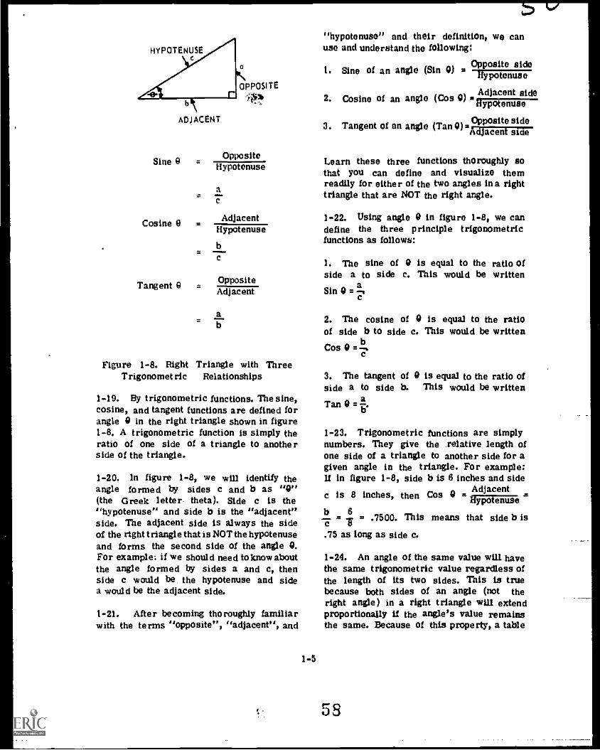
ADJACENT
OppositeSine 9 - Hypotenuse
Cosine 9
Tangent 9 Adjacent
aC
AdjacentHypotenuse
b
Opposite
ab
Figure 1-8. Right Triangle with ThreeTrigonometric Relationships
1-19. By trigonometric functions. The sine,cosine, and tangent functions are defined forangle 0 in the right triangle shown in figure1 -8. A trigonometric function is simply theratio of one side of a triangle to anotherside of the triangle.
1-20. In figure 1-8, we will identify theangle formed by sides c and b as "0"(the Greek letter- theta). Side c is the"hypotenuse" and side b is the "adjacent"side. The adjacent side is always the sideof the right triangle that is NOT the hypotenuseand forms the second side of the angle 0.For example; if we should need to know aboutthe angle formed by sides a and c, thenside c would be. the hypotenuse and sidea would be the adjacent side.
1-21. After be coming thoroughly familiarwith the terms "opposite", "adjacent", and
1-5
"hypotenuse" and their definition, we canuse and understand the following:
1. Sine of an angle (Sin 0) Opposite side
Adjacent side2. Cosine of an angle (Cos 0) mi ymmmae
OppOsite side3. Tangent of an angle (Tan 0) ,-*Adjacent side
Learn these three functions thoroughly sothat you can define and visualize themreadily for either of the two angles in a righttriangle that are NOT the right angle.
1-22. Using angle 0 in figure 1-8, we candefine the three principle trigonometricfunctions as follows:
I. The sine of 0 is equal to the ratio Ofside a to side c. This would be writtenSin 0 =
a
2. The cosine of 0 is equal to the ratioof side b to side c. This would be writtenCos w
b
3. The tangent of 0 is equal to the ratio ofside a to side b. This would be written
Tan 0 = a
1-23. Trigonometric functions are simplynumbers. They give the relative length ofone side of a triangle to another side for agiven angle in the triangle. For example:If in figure 1-8, side b is 6 inches and side
c is 8 inches, then Cos 0 = AdjacentJe--tiypotenuseb 6- .7500, This means that side b is.75 as long as side c.
1-24. An angle of the same value will havethe same trigonometric value regardless ofthe length of its two sides. This is truebecause both sides of an angle (not theright angle) in a right triangle will extendproportionally if the angle's value remainsthe same. Because of this property, a table
58

of trigonometric values was made that liststhe trigonometric values for any angle. Wecan use this table to find the value of anangle if we know one of its trigonometricvalues. Also, using the table we can findthe trigonometric values if we know the valueof the angle. This trigonometric table islocated in your Electronics Handbook, KEP110, figure 31.
1-25. The first and seventh columns of thetrigonometric table in your Electronic Hand-book are headed DEG and contain the degreesfrom 0 to 45, reading down. The sixth andtwelfth columns contain the angles from 45degrees to 90 degrees, reading up. Forangles from 0 degrees to 45 degrees, use thecolumn headings Sin, Cos, and Tan at thetop of the table and read down. For anglesof 45 degrees to 90 degrees, use the headingat the bottom of the table and read up. Theseheadings are to the left o: the 45 to 90 degreecolumns.
1-26. For example: Locate the sine value of32 degrees, Since 32 degrees is between 0and 45 degrees, look in the first and seventhcolumns until you locate 32 degrees. Nowgo to the top of the table and find thecolumn heading "sin". Then come downthe sin column until you are directly oppo-site 32 degrees, this is the sine value foran angle of 32 degrees. The sine value for32 degrees is .5299. Let's work anotherexample: Find the sine value of 54 degrees.Because 54 degrees is between 45 and 90degrees, look in the sixth and twelfth col-umns (reading up the table) until you locate54 degrees. Now go to the bottom of thetable and to the left find the column labeled',sin". Then go up the sin column until youare directly opposite 54 degrees, this is thesine value for an angle of 54 degrees. Thesine value of 54 degrees is .8090.
1-27. If the table does not contain the exactangle or function, we simply take the nearestnumber.
1-28. Since the trigonometric functions havebeen defined from the right triangle, thesolution of a right triangle problem becomesa simple procedure. By the "solution" of a
triangle we mean that we determine unknownsides and unknown angles. In order to solvca right triangle problem. we must know atleast two other measurements of the triangle:either two sides or one side and one angle(excluding the right angle). Merely knowingtwo angles will give us no information aboutthe size of the triangle: we must know atleast one side.
Each equation involving a trigonometric ratio.such as:
Cos 9 "4contains three quantities. If two of these aregiven. the third can be determined. There-fore, to solve a specific problem, you mastselect the trigonometric function whichincludes the unknown part and the two knownparts.
1-29. Refer to figure 1-9 and find angle9. Since we know the side opposite and theside adjacent, we can use the tangent functionto find the angie 9.
a = 40
RRP4 -347
Figure 1-9
Solution. Tan 9
Tan 9
Opposite aAdjacent b
40' 30
Tan 0 = 1.3333
Now look in the Tan column of your Trigono-metric Table until you find 1.3333. The exactnumber is not there: the nearest number is1.3319, so angle 0 is approximately 53.1 degrees.
1-6 59s
se/

1-30. Now use the information from figure1-10 and find angle 0. As we arc given theopposite side and the hypotenuse, we can use
the sine function to find the value of angle 0.
Solution:
REP4 -349
Figure 1-10
San vOpposite a
= _Hypotenuse
.e
80Sin 0 =Tor .8000
Sin 9 s .8000
Now look in the Sin column to find .8000.The exact number is not there; but thenearest number is .7997, so angle 0 isapproximately 53.1 degrees.
1-31. Now that you know the angle, you can
find the length of the other side by usingthe cosine function:
Cos 52.1 degreesAdjacent b
HYPotenuse 100
Find the cosine of 53.1 degrees in thetable; it is .6004.
Now substitute:
.6004 =Tiro
b = 60.04 = 60
1-32. Now we are ready to apply angles.triangles. rectangular coordinate systems.and trigonometric functions to solving ACcircuit problem3.
1-33. Sine wave voltage causes sine wavecurrent in resistive and capacitive circuits.The Voltage and current are in phase inpurely resistive circuits. This relationshipcan be expressed by waveshapes, as shownin figure 1-1113; or as vectors shown infigure 1-1t C. In figure 1-11B, the waveshape
for Ea is the result of adding the waveshapes
for Egi and Egg to get Ea. A single vectordiagram (figure 1-11e(4) shows this addition.
Then we show a vector for total current (11 ).The current is the same throughout a seriescircuit. Since voltage and current are in-phase in a resistive circuit. we can display1 , ERi, ER2, and Ea on the same line in avector diagram as shown in figure 111C(6).The vector diagrams are much easier to work
with than the waveshapes in figure 1-1113.
111
A.
RIeRI
R2
12) --- ER1431 -----..ER2
(41
li1/4'ER1--4"4--..___ER2
___..,3"6
(5) ----Obi
(6)
1-7
60
t
ER1 ER2
C.
Figure 1-11
E,
REP4.2000

A.
C1
C2
B.
Figure 1-12
1-34. In a purely capacitive circuit, the cur-rent is 90 degrees ahead of the voltage acrossthe capacitors. These relationships are shownin figui.e 1-12. The two capacitive voltagesadded together equal the applied voltage.
1-35. We have represented a pure resistivecircuit and a pure capacitive circuit byvectors. Now we are going to represent aseries circuit containing both resistance andcapacitance by vectors. To start, we mustselect a common point for both the capacitorand resistor vectors. Since we are workingwith a series circuit our common pointwill be current. Why? Because the same cur-rent flows throughout a series circuit. IC, IR,and I are the same. Knowing this, we candraw the vectors as shown in figure 1-13A.
ER is on the same line as I because volt-age and current are in-phase in a resistor.Ec is 90 degrees behind I as voltage lagscurrent by 90 degrees for a capacitor. Eais the vector sum of ER and EC. Thereforewe can draw the vector for Ea as shown infigure 1-13B. We may determine the vectorsum through the use of the PythagoremTheorem.
6c
1 1C' R'
A.
ER
I
EC1 A'1A.
EC2/*NIA EA
REP4-350
C.
.1
1-36. Since the voltage drop for a resistor(ER) is developed across its resistance.we place the vector for R on the same lineas ER. Also the voltage drop for a capa-citor is developed across its capacitive reac-tance (X C). Thus we place a vector for XC Con the same line as EC. This is shown infigure 1-13C. We can also draw a vectorfor total impedance (Z ) on the same lineas Ea since applied voltage is felt acrossthe total opposition to current flow in acircuit. We now have a voltage vector dia-gram showing the current and all voltagesand an impedance vector diagram showingall oppositions to current flow.
1-3?. The impedance vector diagram wasplaced on top of the voltage vector diagramto show relationship between voltage andimpedance. However, in practical use, weseparate the two vector diagrams. Theimpedance vector diagram is shown in figure1-14A. For impedance vector diagrams theresistance vector (R) will be the referenceand plotted at zero degrees. The i mpedanceangle (9) is formed by the R and Zvectors.
4411M. 4M.
B.
Figure 1-13
1-8
Ea
I R
61
C.
REP4-2001
0.4
I.

xc
A.
a.
Figure 1-14
RCN -OW:
1-38. The voltage vector diagram *is shownin figure 1-1413. However, for voltage vectordiagrams, Ea is used as the reference pointand plotted at zero degrees. To do this wesimply rotate the voltage vector diagram
R .3K
E0
100y
Xe =4KA
A.
(in the direction show!' in figure 1-44B)until Ea is at the zero degree reference asshown in figure 1-14C. Angle 9 is formedby the En and I vectors and the Ea vector.This angle tells us how mach the totalcurrent is leading the applied voltage. Italso tells us how m..ch the voltage dropacross the resistor is leading the appliedvoltage. The angle formed by the Ea vectorand the Ec vector tells us how much thecapacitive voltage is lagging the appliedvoltage. This angle can be determined bysubtracting angle 9 from 90 degrees as thereis always 90 degrees between ER and Ec.Notice that angle 9 on the impedance vectordiagram has the same value as angle 9 on thevoltage vector diagrams, but has the oppositesign.
1-39. Having combined resistive and capaci-tive components, we are going to solve seriesRC circuit problems. Figure 1-15A is a seriesRC circuit with an AC voltage applied. Weare going to solve for total impedance, phase
R 3K riLL_
.111 411,
X 41( r, /-90
11
Z SKV-53.1
I =20 moA3.1'
ER = 60V Al)"
0 = 53.14
Ec = BOV 36.94,
B.
C.
Figure 1- lb
1-9
G2
REP4-351
r-

angle, Current, and the voltage across eachcomponent.
1-40. To determine total impedance, Z,draw an impedance vector diagram as shownin figure 1-15B. Draw the diagram to scale.The 3 k ohm resistor vector is drawn alongthe zero degree reference line. The 4 k ohmcapacitive reactance vector is drawn at -90degrees. To determine the location of theZ vector, construct a rectangle using the Rand X vectors as the sides. This is shownby the dotted lines in figure 1-15B. The Zvector is drawn as the diagonal of therectangle. The length of the Z vector repre-sents the value of Z. Notice in figure 1-15Bthat Z is the hypotenuse and R and XC formthe sides of a right triangle. Tofindthe valueof Z, use the Pythagorean Theorem. The
basic formula, c - a2 + b2, can be converted
to Z R2 + X 2,
Solution: rr7Z = R + X
= 1(3 x 10³)2 + (4 x 10³)2
=1(9 x 10⁶) 4- (16 x 106)
= 125;-c1.06
= 5 x 10³ or 5 k ohms
1-41. To determine the phase angle betweenthe R vector and the Z vector, use theimpedance vector diagram of figure 1-15Band the trigonometric functions. Becausewe know two sides of the right triangle, Eand Z, we can use the cosine function tcdetermine angle 0.
Cos 0 =adjacenthypotenuse
Cos v =RZ
3 kncos 0
cos 0 2 6000
0 2 53.1 degrees
The exact value of .6000 is not in the trigo-nometric table, but the nearest value is.6004. So angle 0 is approximately 53.1degrees.
1-42. The complete expression for imped-ance in this problem is Z 5 IQ .2 Aladegrees. The impedance angle is negativebecause it is CW from the zero degreereference line. The symbol is shorthand for "an angle of". Figure 1-15B isnow complete.
1-43. To determine total current, use OhmsLaw for AC circuits. In DC circuits, totalcurrent is equal to the applied voltagedivided by the total resistance. In AC cir-cuits, total current equals the applied voltagedivided by total impedance. In formula form:
IEa
I a100 V al_5 k &.53.1°,
20 mA /53,1 °,
1-44. In the formula for current, the voltagewas listed at 0 degrees. When drawingvoltage vectors, Ea is drawn at the zeroreference point. The phase angles for ER,EC and I are measured from the Ea vector.1-45. Phase angles for vectors are treatedmuch like the exponents were treated for pow-ers of ten. To multiply two magnitudes at dif-ferent angles, add the angies. To divide twomagnitudes at different angles, subtract theangle in the denominator fromthe angle inthenumerator. In the previous problem 5 k/-53.1e divided into 100 V /0° equals 20 tv A
3._I °. The positive angle indicates that cur-rent is leading the applied voltage by 53.1°.A negative angle would indicate a lag-ging condition.
I-10 63

1-46. To determine the voltage drop acrosseach component, use 011111S Law.
ER , 1 It
.2 (20 mA all: ) x (3 x10 30 (21 )
GG V air
E = 1 XC C
= (20 mA i 53,1. )x(4x10311 /-90°, )
= 80 V /-36.9°
.- -1 -417. Figure 1-15C shows the complete volt-age vector diagram with the current vectorincluded. The voltage across the resistor isin phase with the current: the voltage acrossthe capacitor is 90° behind the current:and the applied voltage is 53.1° behind thecurrent. Notice. that phase angle relation-ships of the voltage vector diagram are thesame as for the impedance vector diagram.When we multiplied each impedance by thecurrent, the diagram of figure 1-15B changesto that of figure 1-15C. Remember that thevoltage vector diagram's change in positionwas caused by rotating it to place Ea atthe zero degree reference point.
1-48. Now, let's solve another problem.Refer to figure 1-16. Our first step in solvingthis problem is to find the voltage dropacross the resistor. We use the PythagoreanTheorem to do this. Substitute Ea for side
e, En for site a, and E for side b. Then the
formula a * Vc - b2, becomes
ER %(-(T---:e .
j-r71-R a
TC
ER v 47225T27502-
NOTE: Look in your Electronic Handbookfor the squared numbers.
ER = 450,625 - 32,400
ER =%/18
NOTE: Look in your Electronic Handbookfor the square root.
ER . 135V
1-49. The next step is to find 1. Knowingthe voltage drop across the resistor and thesize of the reslitor, we can calculate currentusing Ohm's Law because the current is thesame throughout a series circuit.a 135 V
R 9 x 10311
Next XCcar be found:
XEC
180 VC` 1 15 x 10
-3A
.......
......
Figure 1-16
64
///
Ea . 225V
EC180V
REPO -352
15 mA
= 12 ItS1

225 V=
15 x 10 AZ = 15 x 1044 Q
Z = 15 k
1-50. With the impedance information wehave we can find angle A with trigonometricfunctions.
Using Impedance Vectors
adjacentCosa -
hypotenuse
Cosa= kr.
15 lat
Cos .6000
= 53.1°
ER =135v /53.1°
=15 crtA z5"
EC = 180V /-36.9°,
Using Voltage Vectors
Cos hypotenusete se
La§.1Cos 03
225 V
Cos A 2: .8000
4:1= 53.1°
1-51. The complete voltage and impedancevector diagrams are shown in figure 1-17.Once we have angle 0, it is simple to calculatethe other angles if we remember that Eaand R are plotted at zero degrees and thatthere are 90 degrees between ER and ECand between R and XC.
1-52. Let work another problem with dif-ferent values. Refer to figure 1-18.
First step: Use the, formula Xc = f-E59-- tofind X.
.159 .159 .159X
C- -fC
53 x (.5 x 10-6) 25.5 x 10⁻⁶
lip Ea = 225v
.01$
Figure 1-17
1-12
R r 91(0412
Xc = 12Koz-.191.
65
Z = 15KRA53.1°
REPO- ?003

=.159 x 106 159,000
XC26.5 26.5
Xc = 6 k SI
Next find Z .
Z = IITTC 2C
Z =l(8 x 10³)2 + (6 x 10³)2 Fifth: Find the voltage drop across theresistor.
8K 0
4= R . 8K a
Xc 2 ? Z z 15 uF
REP4-2005
Figure 1-18
Fourth: Find the impedance angle.
...os i = =z lOka
Cos 9 = .8000
A = 36.9°
Z =I (64 x 105) 4. (36 x le) = 100 xER = 1R = (5 x 10
-3) x (8 x 10}3) = 40 V
Z = 10 x 103 = 10 k SI
Sixth: Find the voltage drop across theThird: Find 1 . capacitor
.Ea
50 V , ,,-3
i = """=. =Z 3
= u x lu = 5 inA, EC = 1 X = (5 x 10
-3) X (6 x 10}3) = 30 V
10 x 10 SI C
1-13
66


Chapter 2
SERIES RL AND RCL CIRCUITS
2-1. This lesson covers series RL and RCI.circuits. You will determine voltage drops,current, phase angle, and impedance asso-ciated with FM and RCL series circuits.You will extend your knowledge of vectoranalysis, use of the Pythagorean Theorem,rectangular coordinates, and trigonometricfunctions as they apply to these circuits.
2-2. Recall that inductance opposes a changein current. The expanding and collapsingmagnetic field cuts across the conductorsand induces a counter emi (CEMF) whichopposes the current change. The opposingforce is such that, when a sine wave ofvoltage is applied, the current through apure Inductance lags Ea by 90°.
2-3. Now consider a simple series circuittone path for current) which contains aresistor and an inductor. Refer to figure2-IA. We know that resistor voltage andcurrent are in phase. We also know that
AACTUAL CIRCUIT
ba
the current through the coil lags the voltageacross the coil by 00°. These Phase rela-tionships are shown in figure 2-113. At timeT2, the maximum positive voltage appearsacross the coil; and the current has justbegun to flow in the positive direction. Cur-rent increases to maxinvim 900 later at T4.
2-4. The current and voltage waveshapesacross the resistor are in phase. Currentlags the voltage across the inductor by 90°.The current in the coil is the same as thecurrent in the resistor. We can plot thevoltage vectors with current as the reference(figure 2-2). Figure 2-1 shows ER largerthan EL. Plot these values and draw therectangles.
2-5. Connecting points A and B gives themagnitude and direction of the applied voltage.The angle formed by Ea and I is the phaseangle 0. The sign of the phase angle dependson the current vector position with reference
TO T1 T2 T3 T4111
I pe-90.44
1 4.15ELI35.a
TS T6 T7 T8 T9 T 10111111
PHASE RELATIONS
Figure 2-1
2-1
68
REPO -362

EL E41
Ase- ,
ER
MdP4-3d7
Figure 2-2
to the applied voltage. The phase angle isnegative. Inductive circuit current lags theapplied voltage. Using E as the reference,the vector diagram would be as shown infigure 24. The current vector still has anegative angle. The impedance vector angle.diagram is shown in figure 2-4.
2-6. Note that the impedance angle in theimpedance diagram has the same value asthe current phase angle in the voltagevector diagram, but the impedance phaseangle is positive. Remember the impedanceplane angle is measured from the resist-ance vector.
2.7. Now, let's solve for the unknown valuesfor the circuit of figure 2-5. First, it iswise to look at the known value of any
RrP4 -364
Figure 2-4
circuit; then decide how to proceed. Wefind that we have the values of Ea, XL,and R.
2-8. First, solve for impedance and phase
Figure 2 -3
REP4-363
2-2
Z.1;r X22
L
Z2 /63-7
+XL
36 t 64 =1"iFF = 10 ohms
adjacent=
6 = .6000rCos 9 -ypotenuse
9 = 53.1°
69
REP6 -365
Figure 2-5

Then Solve for current.
1
I
Hence:
Zaa
100 at.10 A L-' 3.1Tr 5110
RR = I R is (10 =lair) x (6L,(e) n 60V/-53.1°,
Them
EL = I XL .= (10/-53,1!)x(8/1e) acnragx
Next plot and label the voltage vectors.
EL 1^ y/3400
4 Ea
101
' -531'ER
I I 'REP4-522
Figure 2-6
2-9. Now,* let's solve the circuit shown infigure 2-7.
Figure 2-7
10 m11
2160
REP4 -3
2 rtrft, 2 (6.28)x(1 x 103)1010 x 10°3)
= 62.8 or 63 Sl
Z 11/7772L 1,4771)2 (63)2
Z 3,969 = %FEW
Z = 225 ohms
Impedance vectors.,
XL =630 Z = 2259
e = 16.3
R =716A
REP4-523
Figure 2-8
Jac! gssnt 2I6QCos 0 hypotenuse 225Q .9600
2-3
70
0 = 16.3°
- 225Vat IA /-16.3°2250 atml:

xR (I A al= ) x (21611 LC') Impedance vectors:
2161/ /-16,3°
xxL . (1 A /-16.3 x (63 410) XL 12K o
= 63V ZILL:
Voltage vectors:
E .63V
4.
4), E0 =22Sv
ER =216V
21L.
REPO -524
Figure 2-9
dm*
R =SKA
2 I 13Ko
-OD
R174-525
Figure 2 11
Ea = I Z = (5 x 103) x (13 x 103) z 65 V
EL = IXL = (5 x 0-3) x (12 x 103) 60 V
EE= IR =(5 x 103) x(5 x 103) =25V
2-10. Let's try one more problem (figure Voltage vectors when current is used as the2-10): reference:
REP4-368
EL =60V
Figure 2-10 67.4°
Z 1,172 73C 2 ER =25V
= j(5 x 10³)2 4. (12 x 103)2
26SV
0.--.-10. I
REPO -526
Figure 2-12
1(25 x 106) 4. (144 x 106) adjacent 25Cos 0 . ---- .J,0
1/7c106 = 13 x 103 hypotenuse 65
13 k ohms 0 = 67.4°
2-4 71
.10

Voltage vectors when applied voitagu im Umreference:
REP: -517
Figure 2-13
In inductive circuits the current always lagsthe applied voltage. The phase angle isnegative.
2-11. The next circuit we will discuss inthis lesson is a series RCL circuit, figure2-14.
Figure 2-14
=110
R 1=120
= 60
REP4-369
2-12. This type circuit contains a resistor,a capacitor, and an inductor connected inseries. The capacitive reactance causes thevoltage to lag the current. The inductivereactance causes the voltage to lead thecurrent. Thus, the two reactances are oppo-site in effect; XE and XC are 180° out ofphase. See figure 2-- 1 5 .
2-13. U L is in henries, to find XL, use theformula XL = 27rfL. If C is in farads, tofind Xc, use the formula
IXC
-2.7rfC
r
XL
xc
Figure 2-15
R4714'1004
2-14. First draw a vector diagram for theimpedance values. See figure 2-16.
2-15. The resistance of the circuit is 12ohms. This is shown as 12 units on thehorizontal axis. As before, plot capacitivereactance at -90° and inductive reactanceat +90°. Note that XL and XC are 180°out of phase with each other. The netreactance, therefore, is XL - XC, or 5ohms of inductive reactance. This is shownas 5 units at LtiC, because XL is largerthan XC. The solid line drawn from point Ato B is the vector sum of all three values.It represents total opposition to the currentflow. Calculate for impedance by using theformula:
L . jR2 4. (XL - Xc)2
2-16. Find the impedance angle using thevector diagram (figure 2-16):
Cos 9 , adjacent==
_a_ 17.0-1-.. .9231hypotenuse
2-5
XL :119
Figure 2-16
REPO -370

Look in the table (figure 31, KEP 110) tofind 9 22.6°.
Z 8 13g /22.6°
2-17. Now that we know the impedance, it isan easy matter to find the current. UseOhm's Law and substitute Z in place of Rin the formula..
The formula now becomes:
26V a:1 2
Z 130 /22.6° 2 amps / -22.6'
2 -18. Current in a series circuit is the samethroughout the circuit; therefore, we canuse Ohm's Law to find the voltage dropacross each component.
ER = 2 (2 A /-22.6°)x(12 Q LCD 2 24 V /-22.6°
This 24 volts across the resistor is laggingEa by 22.6°. Now to find the voltage dropacross the inductor:
ELL (2 A /-22.6°) x dr)
22 V / 67.4°
So, we have 22 volts across the coil. Thisvoltage is leading Ea by 67.4°.
Next, let us find Ec.
EC = pcc = (2 A /-22 6°) x (6 Q 110,)
= 12 V /-112.6°
There we have 12 volts across the capacitorand this voltage lags Ea by 112.6°.
2-19. It is usually an aid to sketch the vec-tors as you solve the problem, such as figure2-17.
2-20. Notice that the current is in phase withthe resistor voltage, lags Inductor voltage by90° and leads capacitor voltage by 90°.
2-6
L g 22V D.Ec g 10V Ls7:44
-22.6°
24V Z2221
20 L22,6,
REPO - .171
Eo g 26V L.=
ob.
-112.6
Figure 2-17
2-21. The voltage drops across the two reac-tive components are in opposite directions,or 180° out of phase. This is true in anyseries AC circuit containing XL and XC.
2-22. Figure 2-17 shows the vector sum ofEL and EC is 10 volts. This vector com-bined with ER, which is 24 volts, equals26 volts. Check for accuracy using thePythagorean Theorem:
Ea
= v ER2+ (EL
Ea
= 1242 + (22 - 12)2
Ea = 274712-
Ea
= /6-77
Ea = 26 V
73
4 Mo

IO 62-23. Lot's try another circuit (figure 2 -20. Find total current and the voltage2-18). across each component.
Figure 2-18
2 850ri
RePob.373
In solving this problem subtract the smallerreactance from the large: reactance. In thiscase, XL - XC is 50 ohms. The resultingimpedance has the same opposition to ACas a resistor of 50 ohms in series with aninductor having a reactance of 50 ohms.
2-24. Now find the impedance value:
Z .=VR2 + (XL - X
C)2
V502 502
= V5-0-0171
= 70.7 0
2-25, Next solve for phase angle:
R 50 CaCos Q =7.= Irm = .7071
Q = 45°
Ea 100 V 0°I n 7 . 4 1.4 amps Lit
Eli
0 I R = (1.4A ithin x (50 0 Le)
= 70 V /....)
EC = I Xc = (1.4 A /-45!) x (850 0 1-90°
= 1190 V i-135°.
EL
= I XL.
= (1.4 A Lz45) x (900 0 LEE)
= 1260 V all'
2-27. Now we can plot the voltage vectors tosee their relative positions and phase rela-tionships. Refer to figure 2-19.
70y
/Ec = 1190V /135°
Az 1260V *e5°
E0 . 100V Al.-454 /*
"ER =70V / -15°
t 1.10/_45{:
Figure 2-19
REPO-174
2-28. Observe that the voltage across the coiland capacitor are much latger than theapplied voltage. Since these values are Inopposite directions (180° out of phase), theeffective voltage across the two reactancesis 70 volts. The vector sum of reactive andresistive voltage equals the applied voltage.
2-7
74

Chanter 3
SERIES itc, I2 L, AND nu CIRCUITS
3-1. This lesson discusses the factorsaffecting power in series RC, RL and RCLcircuits.
l -2. Remember that power is defined as the"rate of doing work" Electrically, it isexpressed in watts, or in kilowatts (thou-sands of waits).
3-3. In DC, or purely resistive AC circuits,power is simple to calculate. Current is maxi-mum when the valtage is maximum; or inother words, current and voltage are inphase. Power equals voltage times current.Maximum power is delivered to the load.
3-4. However, in reactive circuits, currentwill be either leading or lagging the appliedvoltage. That is, tne current and appliedvoltage are out of phase. Power delivered tothe load is not equal to applied voltage timescurrent.
3-5. Figure 3-1 illustrates current, voltage,and power in an AC resistive circuit. Thewaveforms indicate instantaneous values.
3-6. Em and Im denote maximum or peakvalues of voltage and current, respectively.
CURRENTVOLTAGE 0
-Cm
POWER
AVERAGEPOWER
7
Note that voltage and current reach theirmaximum positive (above the zero line) andmaximum negative (below tbe zero line)peaks together (in-phase).
3-7. Note that the power pulses are allpositive. It's simple to understand whenyou remember algebraic multiplication. (A
negative times a negative equals a positive).Resistive power gives off heat or light oris used in doing other "work." This iscalled true power, Pt.
3-8. In the case of resistive AC circuits,true power can be found by the followingformulas:
Pt ExI
Pt r. IZ x R
E2Pt
R
3-9. Figure 3-1 shows Pm as the peakpower when peak values of current and volt-ages are multiplied. Calculating with effective(rms) values of voltage or current results inaverage power Pav
railIMIE111110111MEIRIMIONAnurirmormum
Figure 3-1
3-1
75
REPO -331

Em
EIVAIINIIIMINNIIIItilrimmommeW4 ii31151.11111M'MEMO LI
PmINUM
rgi4 r.1
i''-Pm VECTOR DIAGRAM
E
0
Figure 3-2
CURRENTAND
VOLTAGE
AVERAGEPOWER
RE:..332
3-10. Now, note figure 3-2. It representscurrent, voltages, and power in a purelycapacitive circuit.
3-11. The product of instantaneous values ofthe 906 out-of-phase values of current andvoltage gives a waveform having positiveand negative values. (Multiplying like signsgives plus, and unlike signs gives minus).Changing every quarter cycle, figure 3-2
shows first positive current and negativevoltage; then both are positive; then positivevoltage and negative current; then both arenegative. You can see that the average powerin a purely capacitive circuit is zero (equalamounts above and below the zero referenceline).
1m /AMAMI/LIMNEm.
0 MIMMTAMMIll-I UMW:AIMS/_E iiimmumiam
0VIP r FiFillrraffill YI
IN
Fieure 3-3
REPO -333
3-12. What is actually happening is that thecapacitor stores energy on One half alter-nation', it returns it on the next half alter-nation. So, no energy is ACTUALLY used,although there is an APPARENT expenditureof energy. This appa rent expenditure of ?lie rgyis called apparent power, P.
3-13. The same operation takes place in apurely inductive circuit. The coil storesenergy on one half alternation, and returnsit on the next half alternation. The averagepower of a purely inductive circuit is zero.
3-14. Figure 3-3 shows the current, voltage,and power relationships in a circuit con-taining resistance and inductance. (The sametype of analysis could be applied to aresistance-capacitance circuit; except thatcurrent leads the voltage across the capacitor).
3-15. In figure 3-3 the voltage leads thecurrent by an angle equal to theta (9).Since the voltage leads current by the phaseangle, there is a period (equal to the phaseangle) when the product of E and I is nega-tive. This is the period of time when storedenergy is returned to the circuit from thecoil.
3-16. You know how to find impedance values.voltage drops, currents, and phase angles, inRC, RL, and RCL series circuits. If you haveforgotten, review now before proceedingfurther.
3-17. Now you can say that in an AC circuittwo types of power are known to exist. Theseare true power (Pt), and apparent power (Pa).
3-2
3-18. Let's give these two terms a defini-tion; True Power is the actual power dissi-pated by the resistance of the circuit and isexpressed in watts. An example is powerloss in the form of heat. Apparent Poweris the product of current and voltage, and isexpressed in volt-amperes. The reactivecomponents of a circuit -apparently" dissi-pate power: but actually do not.
76

Expressed as equations:
Pt= ER XI
Pt a (Itt)2 x R
(ER/2
p at R
Pa .EA
x I
Pa = Oil x Z
(Ea?
z
Where:
Pt is true power expressed in watts.
Pa is apparent power expressed in volt-amperes
Ea is applied voltage
Z is impedance
ER is voltage across circuit resistance
3-19. Now you know the difference betweentrue power and apparent power; let's workproblems concerning true power and apparentpower.
3-20. In the circuit of figure 3-4, determinePa and Pt.
Solution: Draw two vectors to represent ERand E. (Refer to figure 3-4).
First, solve for Ea:
i2"
35FTiEa = ER + EC + 50
. 3)/72i- 61V
3-3
A
ER = 35V
REP4 -334
Figure 3-4
Now, solve for current:E
Z2
40061 V
n = 152.5 mA
Next, solve for apparent power:
= SOV
a 35V
2 4000
b et
P..
= Ea I = 61 V x 152.5 mA = 9.3 VA.
Finally, solve for true power
Pt = ER1 x I = 35V x 152.5 mA = 5.34 watts
77

3-21. A reactive element in a circuitrequires power which is not dissipated. Ifwe add an opposite element to balance outthe reactive effect (i.c., add XL equal toXc so that Xc = XL), the circuit becomespurely resistive; and all power is dissipated.
3-22. With these facts in mind, let's proceedto the next item of discussion. This is thePower Factor or PF.
3-23. Power Factor is the ratio between truepower and apparent power.
power PtPower Factor - true p
or PF =apparent power Pa
Apparent Power atrue power Pt
power factor or Pa = PF
or we can also say that;
True power = Apparent power x Power Factor
or Pt = Pa x PF
3-24. Let's review vector diagrams to betterunderstand the phase relationships. Given anRL circuit, we can plot the vector diagrams(figure 3-5).
CIRCUIT
m .11, 4011111. 411
EL
ER
VOLTAGEVECTORS
E I
0I
3-25. U impedance is multiplied by current,we obtain the voltage drop across theImpedance. We can apply this to the vectordiagrams of figure 3-5. First, multiply eachIMPEDANCE vector by the current, and wehave a VOLTAGE vector diagram.
3 -26. Now, multiply each voltage vector bycurrent and what do we have? Power, ofcourse.
Ea I = Pa
ER1 = Pt
EIaP (reactive)
3-27. We can plot these values, using currentas the reference; we see the power relation-ship. The vector sum of resistive power(Pt) and reactive power is apparent power.The ratio of true power to apparent power,is defined as power factor; it is also thecosine of the phase angle.
3-28. We can use the vector diagrams andexpress power factor in four ways:
PtPF =
afXL Z1
1
R
IMPEDANCVECTORS
Figure 3-5
3-4
POWER VECTORS
78
REPO -335

1)10 =ft!T-A
PFZ
= Cos 0
3-29. Now let's work some problems to applythese principles: A circuit has an apparentpower of 500 volt-amperes and a powerfactor of .7071. What is the true power?
Pt pa x = 500VA x .7071 = 353.55 watts
You can see it's easy to find the true powerwhen Pa and PF are known. To check thisanswer: divide true power by power factorPt
and the answer will be APPARENTPr 0 = 53.1°
POWER, 500 volt-amps. Now, proceed tofind PF. Use the same figures that were
0100V
F 1590Hz
7 /R 300
XL
Figure 3-6
R 30Cos = 7 = = .6000
used for Pt and Pa.
Power Factor = True PowerApparent Power
353.55 wattsPF - .7071500 volt-amps
Expressed as a percent this power factorequals 70.7%.
3-30. Let's solve another problem. Usingfigure 3-6, solve for impedance, phase angle,power factor, current, apparent power, andtrue power.
Z/1712
1.
2
"C
Z = 900 ilrFE10
Z = 50.n-
At what angle is the 50 ohms of impedance?Use the COSINE FUNCTION to find out.
3-5
79
REP4 -336
Also the power factor Is equal to the cosineof the angle 0.
pr = Cos 0
PF = .6000 or 60%
Continuing with the problem:
I TL
Ea100
= = 2 amps /#53.1°
Pa = Eal = 100 V x 2 A = 200 volt-amperes
Pt - Pa Cos 0 = 200 VA x .6 = 120 watts
3-31. For figure 3-7, first find Z by thePythagorean Theorem:
Z = V(12 x 102)2 + (5 x 10²)2
=V144 x 104 + 25 x 104
169x104
= 13 x 102 or 1300.n.

xLr
1
1
1---10R
REP4-JJ7
Figure 3-7
Then solve for current:
EI = za
130 V1300 Si
.1 A
Now calculate apparent power:
Pa = Ea 1
= 130 V x .1 A
= 13 VA
Now we are ready for true power:
Pt = 12R
a (.1 A)2 12002
= .01 x 1200
= 12 W
Finally solve for PF:
PtPF = -15
a
3-6
12 W13 VA
* .0231
342. If you have an RCL circuit, you canuse the came method for finding Pt, Pa,and PF. But you must first find the dif-ference between X
Land X
C.See figure
3 -8.
aXL t 2000 0
_. Z
*SR t 8000
X .10000
REP4-338
Figure 3-8
R z 8000
First, we will take XL - XC (2000 - 1004This gives us a net reactance of XL = 1000ohms in series with R = 800 ohms.
Now solve for Z:
-, R2 (31---,xd2
. Vow? + (1000)2
= 111T1 TC 104
= 1280 SI
80

Next determine current: Next solve for Pt:
Ea128V Pt *I2
x. ft * (.1A)2
x FMZ ' WM
= .1A
Now calculate Pa:
Pa= Ea X 1 = 128V x .1A
At 12.8 VA
e . ,
3-7
81
a .01 x.800
le 8 W
Finally determine PF:
.,_r 1 8Wi
124 VA
= .6259
/73

6$
Chapter 4
PARALLEL ItC, no AND RCL CIRCUITS
4- t. We learned many things in StudyingDC parallel circuits that we can apply toAC parallel circuits. We found that theapplied voltage is common to all componentsand total current is the sum of the branchcurrents. In AC parallel circuits voltageis common to all branches and total currentis the VECTOR sum of the branch currents.
4-2. As you know, current leads voltageacross a capacitor by 90 °. In a coil, currentlags the voltage across the coil by 90°.This chapter discusses current, voltage, andpower relationships in parallel RC, IIL,and RCL circuits.
4-3. Let's use a parallel RCL circuit,as shown in figure 4.1. Observe that theapplied voltage (Ea) is common to theresistor, capacitor, and coil. We will plotthe various current vectors with referenceto the applied voltage.
REP4 -283
Figure 4-1
4-4. We know that the current through aresistor is in phase with the resistor volt-age. So the vectors are as shown in figure4-2.
IR
Figure 4-2
ao. Eas ER
REP4-284
4-5. The current through a capacitor leadsthe capacitor voltage by 90°. The vectors areas shown in figure 4-3.
it
4-6. Theinductoras shown
1
Igo E E;
ReP4o285
Figure 4-3
current through a coil lags thevoltage by 90°. The vectors arein figure 4-4.
I L
Ea = EL
REP4-.286
Figure 4-4
4-7. If we plot all three vectors on the samereference, we have a vector diagram fer aparallel RCL Circuit. Refer to figure 4-5.
4-1
lc
it
pp. Ea = ER = EL a Ec
REP4-287
Figure 4-5
4-8. Now, we will discuss how to solve forbranch currents, total current, total imped-ance, and phase angle (Theta 9).
4-9. Let's solve for these values in theparallel circuit illustrated in figure 4-6.
Figure 4-6

4010. The applied 60 volts is felt acrossthe resistor; it is likewise felt across thecapacitor. We can use Ohm's Law to findIn and 1 .
C
Er,1It R
is t1 Jo v Le, 20 amps i_tr.art
_EC 60 V hirc x 4 40/48/.°
C
4-11. We have 20 amps through the resistorand 15 amps through the capacitor. Now, wemist observe the phase relationships ofthese currents. The total current is thevector sum of the individual branch cur-rents. Take a look at the vectors that repre-sent the current in our circuit in figure4-7.
IeIlorIMr,11=11=1111
1
I
NJ ON- EaiR
Figure 4-7
REPO - ?99
4-12. Current through the capacitor andcurrent through the resistor are 900 out ofphase. To add the vectors, we complete aparallelogram as shown by the broken lines;the resultant is total current. The value ofIt can be determined by measuring the lengthof the It vector. The phase angle between Itand IR can be measured with a protractor.We. can also find the value of It by applyingthe Pythagorean Theorem:
It = '11R 2 * IC22"
1(20)
2* (15) 2
= "sIrTi) 0 47i E = ViF = 25 amps
4-13. To find total impedance. use Ohm'sLaw, substituting Z for R.
4-2
Ea 60 . 2.4 ohmsi' * It * 25 A
4-14. You should have noticed that It islarger than IC or IR but smaller than thearithmetic sum of lc and IR. Also totalimpedance is smaller than the smallestresistor or reactance value in the circuit.
4-15. To solve for the phase angle, we canuse the cosine function.
Cosh =
9 = 36.9°
4-16. RL circuits are solved in a likemanner. Refer to figure 4-8.
20 AI5 7 ' '8000
Figure 4-8
8Q
PEP4-200
, Ea40 V LC
`R -ir tov ByL = 4 amps Zp°
Ea40 V Lit
1 L =T" - 8 u e = 5 amps Zx_90"°acL
4-17. Remember, current in an inductivecircuit (IL) is 90° behind ER. This is shownin the vector diagram in figure 4-9.
Total current is the vector sum of ILand 6. We can use the Pythagorean Theoremto solve for It.
83
75-
AM.

REP4 -291
Figure 4-9
ItFF
4.t R *IL = (4) (6)2
= \RFT25 F11 = 6.4 amps
4-18. To solve for total impedance, we useOhm's Law.
EZ
It4C1 V = 6.25 ohms2 6.4 A
4-19. Total impedance in a parallel RLcircuit is less than the value of X
Lor R.
4-20. Last, we will find the phase angle.
Cos 0 =- R6250it = 6A A
9 = 51.3°
4-21. sow, we should be able to solve acircuit containing a coil, resistor, and capa-citor (RCL circuit). Refer to figure 4-10.
Figure 4-10
REP4 -292
442. The work for this circuit is easy;find the branch currents first by Ohm'sLaw.
Ea 180 V ar'n 7 uTUrje I lir" 41):
Ea 160 V Lir...1 a '''''. 1 80 f Zria,c X c
Ea 160 V./.0.!L X 320 S'i Er
2.5 aMps bale1 = -L
4-23. The vectors for this look like figure4-11.
4 lc 2 AMPS
IR 2 1 AMPEa
tL40.5 AMP
REP4 -293
Figure 4-11
4-24. Use Pythagorean Theorem to solve fortotal current. You must SUBTRACT thesmaller reactive current from the largerreactive current to solve this type problem.
It = 11 R2 + (1C - 1L
)2
2 1(1)2 4- (2 - .5)2= V(1)2 4- (1.5)2
= VT + 2.25 = 5 = 1.8 amps
4-25. Solve for
It--he
phase angle.
Cos 0 . T - =11.8
A -A
4-3
84
9 s 56.3°

4-26. Vectors Ior this solution are shown in Themfuture 4-12. E
OIN411,0Z A It Jil..IL A 1000 ohmst .85 A
+ Ic
*2A............ .1=1.
V
* I,8A
IL.
*0.5A
REP4-294
Figure 4-12
4-27. Let's analyze another circuit. Referto figure 4-13.
REP4-295
4 -29. When the applied voltage is not given,you can solve for total impedance by usingthe assumed voltage method. If the appliedvoltage is not given, then assume a voltageand calculate the current through eachbranchof the circuit. Combine the branch currentsusing Pythagorean Theorem (or vectors)to determine total current. Use total cur-rent and the assumed voltage to calculatethe impedance. Regardless what voltage isassumed, the impedance will be correctbecause impedance is a ratio of currentto voltage,
4-30. Let us again refer to figure 4-10.In this circuit total current was 1.8 A.Using Ohm's Law solve for Z .
Z
Ea160 V - 88.8 g1.8 AIt
Now let us take the same circuit, but arbi-trarily pick a different applied voltage. Inthis case use an assumed voltage of 480volts. Following the procedure for theassumed voltage method, first calculate theindividual branch currents and then deter-mine It.
Figure 4-13 First:
Ea4-28. Let's first find It and then determine IR= R r. 160 0 '''''total impedance. Individual branch invped-ances can be solved using Ohm's Law. Ea
480 V
2 2
It n \lEft 1' (IC IL)
a 1/(.3)2 4- (.8 - .1)2
= J(.3)2 + (.8)2 = 1,/.(T4 .1773T1
IC= -: 6A
XC80 0
Ea 480 VIL KL
=1, =320 0 = 1.5A
Then:
It = VOR12 4- (IC - 1 L)2
= .85 amps - J32 4 (6 ._ 1.5)2
4-4 85
97
01.

rasumfa- 41.46.4 dlifa 11.
U 4.82
1420.25
5.408 A
4-31. Now use It to solve for Z
Ea480 V
Z 4 It 5.408 A = 88.8 S1
Notice that the impedance is the same valueobtained when the value of the applied voltagewas known. This method may also be appliedto parallel RC and RI. circuits.
4-32. Now, let's discuss power and powerfactor in parallel reactive circuits.Remember, purely reactive components donot dissipate power. Only the resistance in acircuit dissipates power. This is called truepower.
4-33. When reactive components and resis-tive components are connected in a circuit,the circuit appears to use more powerthan it actually dissipates. This is calledthe apparent power of the circuit.
4-34. Apparent power (Pa) of a parallel RCLcircuit is: Pa = EaIt. The formula for truepower (Pt) is: Pt =ERIR, Power factor (PF)
Ptis: PF 2 Pa
4-35. Using figure 4-13, determine Pa, Pt,PF, and the phase angle 9.
P E Ia a t . 850 V x .si5 A = 722.5 VA
Pt = ERIR z 850 V x .3 A = 255.0 watts
Pt 255 W or 35%PF = Pa P" 72-2-WA
Cos 0 z .3529
0 = 69.30e
4 -3d. Important principles to keep in mindwhen solving simple parallel IICL Circuits:
1. Branch currents may be different, butvoltage is the same across all components.
2..Vector diagrams use voltage as thereference, with currents added vectorlally.
3. Do not attempt to draw impedancediagrams for parallel circuits.
4-37. Component Testing
4-38. Now, let's discuss how to determinewhether a capacitor is good, opened, orshorted. A capacitor that is opened, shorted,or partially shorted (leaky) is useless becausethe basic function of storing a charge is lost.A leaky capacitor is one in which the dielec-tric has lost its insulating ability under theconstant pressure of the applied voltage. Aleaky capacitor will have a low resistancevalue. A good capacitor of paper or ceramicwill have resistance readings upward of 1000megohma, which for our purposes can beconsidered to be infinite resistance.
4-39. Generally a capacitor can be checkedwith an ohmmeter. Before you use theohm:neter you must disconnect the capacitorfrom the circuit and make sure the capacitoris fully discharged. The ohmmeter will sup-ply the voltage for checking the capacitor.Keep your fingers off of the connectionssince body resistance will give erroneousindications. Always use the highest scale onthe ohmmeter when checking capacitors.
4-40. When you connect the ohmmeter acrossa good capacitor, you will get momentarydeflection of the meter and then the indicator
4-5
86

4
will return to infinity. This is caused by thecharging action of the capacitor. With somecapacitors it is difficult to detect this momen-tary deflection. In this case a practicalcheck is to replace the capacitor with onethat you know is good.
4-41. When subjected to high voltages capa-citors may arc through the dielectric, causinga short. A short can also be caused by ageor high temperatures. When you connect anohmmeter across a shorted capacitor themeter indicator will deflect to zero. Thisis a sure indication of a shorted capacitor.
4-42. When you connect an ohm veter acrossan open capacitor the indicator will remainat the inifinite reading. Some precautionmust be exercised because a very highresistance reading is normal for capacitors.In addition, we must remember that smallvalued capacitors do not need much chargingcurrent and therefore will not show adeflec-tion on the meter. As a result care must beexercised when checking capacitors foropens. In these cases it may be more prac-tical to substitute a new capacitor.
4-43. Inductors, like capacitcrs, can bechecked using an ohmmeter. You must
remember that in using an ohmmeter tocheck coils you are measuring the DCresistance of the coil. The coil normallyhas very low resistance. This presents aproblem when troubleshooting coils.
4-44. A common trouble with coils is anopen. This type of trouble is easy to findbecause it lacks continuity. When an ohm-meter is placed across a coil with an openthe meter will indicate an infinite ohms.The open inductor may be caused by cor-rosion, excessive current, or age. Smallwire can be easily damaged.
4-6
97
4-45. Unlike opens, shorts in inductors aredifficult to locate. When an ohmmeter isplaced across an inductor that is shorted,the meter will indicate zero ohms. Caremust be exercised. Remember that somecoils have just a few turns of wire andnormally show a zero ohm reading. It israre that you will have a completely shortedinductor. Normally just a few turns short.together. This condition cannot be definitelychecked with an ohmmeter because theresistance will change only slightly. Whentroubleshooting a coil that is suspected ofhaving a short, the best check is to sub-stitute a new coil.
87

Chapter 5
SERIES RESONANCE
5-1. This chapter is a continuation of yourstudy of the series RCL circuit. In the lastiesson, inductive reactance and capacitivereactance had opposing impedance effects.If the frequency applied to a series RCLcircuit causes XC and XL to be equal,the circuit is resonant. In this chapter,we study the conditions which exist when aseries circuit is RESONANT. Then, weanalyze circuit operation by varying fre-quency and Impedance values above and belowthe resonant point. We will discussBANDWIDTH and SELECTIVITY.
5-2, Resonant circuits are used in radarto control the frequency of operation oftransmitters and receivers; in radio to selectone station from many; and in telephonecircuits to provide communications formillions of people.
5-3. A series resonant circuit consists ofinductance, capacitance, and resistance; asshown in figure 5-1. Observe that XL =XC. Draw an impedance vector diagram, andnote that XL cancels X. This leaves resis-tance as the only impedance. This is theminimum Impedance possible in this seriesRCL circuit. Total current equals appliedvoltage divided by this resistance:
EI =--
Z=1
15
Q
0 V- = 2 amps
Figure 5-1. Series Resonant Circuit X = XL C
Fe
5-4. We can list important points concerningseries resonance:
a. XL * XC
b. Z * R * minimumEc. I 2 * maximum
d. ER = Ea
e. EC r. EL
5-5. The frequency which causes the capaci-tive reactance and inductive reactance to beequal is the RESONANT FREQUENCY (fr).When the resonant frequency is applied, thecircuit is a RESONANT CIRCUIT. If a vari-able frequency power source is applied, andthe frequency is varied, there will be onlyone frequency which causes resonance forany given series RCL circuit.
5-6. In the circuit of figure 5-2, XLis larger than XC. This circuit is NOT .
at resonance. If we decrease the appliedfrequency, the circuit can be broughtto resonance. The circuit of figure 5-2is ABOVE RESONANCE because the frequencymust be decreased to make the values ofX
Cand XL equal.
5-1
88
Figure 5-2

V
Figure 5-3
5.7, In figure 5-3, XC is larger thanXL. This circuit is BELOW RESONANCE.The frequency must be increased to makeXc = XL.
5-8: Let's compare impedance vectors forthe three conditions of the above circuit(figure 5-4).
For the resonant circuit (A) the reactivevalues cancel leaving only resistance. Theimpedance angle is 0°. Recall that this isalso the phase angle, and the cosine of 0°is 1. (Check this in your trigonometry tables).Thus, the power factor of a series resonant
XL l
,., I--..R 2 2 .1 C
RESONANCE
A
circuit is 1; PF * Cos 0. Apparent poweris the true power (Pa = Pt).
5-0. The above - resonance impedancitdiagram (figure 6 -4B) has a positive phaseangle; the below-resonance impedance dia-gram (figure 54C) has a negative phaseangle. In both of these cases the powerfactor is less than 1 and true power is lessthan apparent power.
5-10. Now, we can add more importantpoints, concerning series resonance, to thelist in paragraph 5-4.
f. 0 = 0°
g. PF = 1
h. Pa . Pt
5-11. In any series RCL circuit, the onlyfrequency at which capacitive reactance andinductive reactance are equal is the resonantfrequency. To solve for the resonant fre-quency, use the formula
1 e .159f or 1 =-millr - 2 -rriCe r
Xcif
ABOVE RESONANCE
B
Figure 5-4
5-2
89
0
Xc - XL
xc T
8ELOri RESONANCE
C

FRVP.1- 100
Figure 5.5
5 -12. Figure 5 -5 shows the relationshipbetween XL and XC as frequency increases.There is a point where XL and Xc areequal. This is the resonance point.
5-13. Refer again to figure 5 -5. At 0 hertz,Xc is maximum and XL is zero. As fre-quency increases toward the resonant point,XC is larger than XL, so the circuit iscapacitive. At resonance XC XL, so thetotal impedance of the circuit is resistive.As the frequency increases above resonance,XL is larger than XC, and the circuit isinductive. Figure 5 -6 shows the resultingimpedance diagram. At the resonantfrequency (fr) total impedance is resistive;impedance increases off resonance. ABOVE
A
I200 300 F, 500 600 700
Figure 5-6
Z -
RE 30 i
5-3
X * ISo
Xc* 10o
XL - Xc
Figure 5 -8
R
resonance the impedance is inductive, andBELOW resonance it is capacitive.
5-14. Figure 5 -6 goes one step further andshows the CURRENT CURVE. At minimumimpedance current is maximum.
5-15. Now, let's go back to vector analysisof series E1CL circuits. At resonance,XL = XC and the impedance of the circuitis equal to the resistance. XL and XCare 180° apart, they cancel out. Just resist-ance is left, so Z * R. Figure 5 -8 shows acircuit to be inductive or ABOVE RESON-ANCE. XL is larger than XC. Figure 5.8
shows a circuit to be capacitive or BELO%RESONANCE. Xc is larger than XL.
5-16. Deleted to include Figure 5-7.
5-17. Deleted.
5-18. ABOVE RESONANCE refers to acircuit with an applied frequency H1GHEthan the resonant frequency. ABOVE RESON.NANCE XL is greater than XC and the cir-cuit acts inductively. By using the parallelo-gram method and with R as a reference, wecan plot the impedance of such a circuit.Z is the vector sum of the excess XL andthe H of the circuit. (See figure 5-8).
5-19. BELOW RESONANCE refers to a cir-cuit with a frequency LOWER than the resonantfrequency. BELOW RESONANCE, XC isgreater than XL. (See figure 5 -9).
90

RL'P4- 304
Figure 5-9
5-20. When the frequency is below theresonant frequency, the circuit actscapacitively. The opposition to the generatorconsists of resistance and capacitive reactance(vector sum of R and XC - XL). With anapplied frequency higher than the resonantfrequency, XL Is larger than XC; now theimpedance becot.,es the vector sum of R andXL XC. At this time, the generator"sees" only resistance and inductivereactance. (Draw the impedance diagrams toprove this for yourself.
5 -21. The impedance curve of a seriesRCL circuit is shown in figure 5 -10, and thephase angle is 0°, XC and XL are equal.The only impedance at that time is theresistance of the circuit. We are then atresonance, impedance is minimum, andcurrent is maximum.
10,000
8,000
6,000
4,000
2,000
Z IN I II i
OHMS1000 2000 3000 4000 5000
FREQUENCY
Figure 5 -10
REPO -529
CAPACITIVE
30
900
60°
DEGREES LEADING
FREQUENCY ---''''...11r
5-4
'EGRESS LAGGING
300
60°
90°
Figure 6-11
INDUCTIVE
REP4- 530
5-22. The farther you are from the resonantfrequency of 3000 Hz, the higher the imped-ance. As you approach the resonant fre-quency, the impedance decreases until, atthat exact point where XL = XC, the circuitIs at resonance; the impedance is MINIMUM;and the current is maximum.
6-23. Now, let's consider the relationship ofcurrent and voltage in series resonant circuits.
5 -24. Connect an ammeter in the circuit infigure 5-12A at points A, B, or C; the
RN.
ER = EaOP ..111.I
Xc =XL
Figure 5 -12
91
REPO -305
sgS

R a 200
A. CIRCUIT
Et
B. VOLTAGE REFERENCE
Figure 5-13
CURRENT indication will be the SAME. ThisIs a series circuit with one path for current.
5-25. Deleted.
526. The voltage across the inductor leadsthe current through the inductor by 90°, andthe capacitor voltage lags the capacitor cur-rent by 90°. The voltage across the resistoris in-phase with the current. When you havea resonant circuit, the capacitive and in-ductive reactances cancel each other; and atthis time the CIRCUIT CURRENT, the RE-SISTOR VOLTAGE and the APPLIED VOLT-AGE are all in phase.
5-27. A resonant circuit is shown in figure5-12. Reactance values cancel; Z r-- R, and Iand Ea are in phase. The voltage drop acrossthe resistor equals the applied voltage.
5-28. Figure 5-13A shows a circuit that isBELOW RESONANCE. Two separate vectordiagrams (figure 5-133 and C) show Ea andI as references. The circuit is capacitive
A. CIRCUIT
Ec - EL
Et
C, CURRENT REFERENCERtP4-.70b
Ea
because current is LEADING the appliedvoltage. The angle is 45° because the netreactance equals the resistance.
5-29. Now, for ABOVE RESONANCE, figure5-14A shows XL a 60 ohms and XC a 40ohms. Now the vector diagrams of EL, Ec,I, and ER, and Ea will be as shown In figure5-I4B and C. The circuit is inductive be-cause current LAGS the applied voltage. Theangle is 45° because resistance equals thenet reactance. Notice Ea and I are each usesas a reference vector.
5-30. Deleted.
5-31. Refer to figure 5-15andnote the shapeof the current curve of a typical seriesresonant circuit. From its peak at fr, currentdrops off at frequencies above and belowresonance. There are two points on thecurve which are 70.7 percent of the peakcurrent value. They are calledHALF POWERPOINTS. The frequency range between thehalf power points is called the BANDWIDTH(BW) of the resonant circuit.
B. VOLTAGE REFERENCE
Figure 5-14
5-5
92
Ec
C. CURRENT REFERENCEREP4-307

I
.IND ftMl ,... 111 MIN= wlillm. 111 =NM, MM.
HALF POWERPOINT LEVEL
Ifit Ir 112 _____,,,.
I 1411-101I
A P
10-- 2 kHz
11.S kHz I
BANDPASS
Figure 5-15
E
SW a I kHz
REP41- 308
5-32. The resonant frequency in figure 5-15
is 1,5 kHz; at this point current is maximum.Current falls to .707 of its maximum valueat 1 kHz on the low side and 2 kHz on thehigh side. To determine the bandwidth,use the formula: BW = f 2 - fl. The band-width in this case is 1 kHz.
5-33. Figure 5-15 also shows that currentdrops off rapidly when the frequency appliedto the circuit is below I kHz or above 2
R (LOW RESISTANCE)1
HIGH 0
R2 (MEDIUM RESISTANCE) --
R3 (HIGH RESISTANCE)LOw 0
kHz. Frequencies between the two half powerpoints are in the BANDPASS REGION. Thebandpass frequencies then cover 1 kHz to2 kHz.
5-34. Increasing the resistance of a resonantcircuit has no effect On the resonant fre-quency point. The resonant frequency formulashows this%
fr
.15s
VTc
On the other hand, current at resonance isdetermined by resistance only, since XC andXL cancel. Increasing R, then decreasesresonant frequency CURRENT. It does NOTchange the RESONANT FREQUENCY. Chang-ing circuit resistance does change "circuitQ,.
4-35. "Q" is defined as the ratio of energystored (by the reactive components) to theenergy dissipated (by the resistance). Thisratio can be expressed as:
2P
reactiveIXL XL
true l`R
ollwwrm MO1111 .i =1111111111. ...em
6W
i
Figure 5-16
5-6
a RESONANT FREQUENCY
93
-EP4- 309

XL
1L0
Figure 5-17
itiaPd. 52 0
Increasing the value of series resistance,lowers the "Q" of the circuit.
5-36. "Circuit Q" applies to resonant cir-cuits. "Circuit Q" is the ratio of XL tothe total resistance in the circuit.
5-37. Figure 5-16 shows current curves whichresult from changing resistance in an RCLcircuit. Changing the circuit resistance fromlow to high changes the circuit Q from HIGHto LOW.
5 -38. When the resistance is small, currentat resonance is high, and the slope of thecurrent curve is steep. A HIGH Q circuithas a rapid decrease in current as fre-quency is varied above and below fr Thiscauses a narrow bandwidth. Only a narrowband of frequencies will be between the halfpower points.
5-39. A HIGH Qcircuit thus has high SELEC-TIVITY. We define selectivity: Ability toselect a narrow band of frequencies andreject all others. High Q resonant circuitsare used in radio or television so you canselect one broadcast station at a time.
5-40. When resistance is high In a seriesRCL circuit, current at resonance is low,Q is low, and the current curve shows abroad frequency response. Bandwidth is wideand circuit selectivity is poor.
5-41. Where good selectivity is required,the RCL circuit usually has no resistorcomponent. The total resistance in the circuitis the internal resistance of the coil andthe "distributed" resistance of the wiring.
VARIABLE L AND C
Figure 5-18
5-42. Have you noted the relationshipbetween Q and BANDWIDTH? Examine the
fr
Qformula: BW u --I A LOW Q circuit will
have a larger bandwidth than a HIGH Qcircuit. The LOW Q circuit will be lessSELECTIVE. What about resistance? It isDIRECTLY proportional; if resistance is high,
X
BANDWIDTH will be wide. Q is in-f
creasing ft will decrease Q. BW = ir.
Decreasing Q causes BW to increase.
5-43. Figure 5-17 is a hight,/ circuit:, Animportant property of this circuit is that itsIMPEDANCE is low AT RESONANCE andincreases rapidly as the frequency is changedabove or below resonance. Q is the ratioof XL over R and is considered high if it
is 10 or more. Q uXL 1000nr . . WO for thls
circuit.
5-44. Inductance and capacitance determinethe resonant frequency of a circuit: wheneither one is changed, the resonant frequencychanges. When you tune your radio, you areactually changing a variable capacitor; andas a result you are tuning a circuit to thefrequency of the radio station you want tohear. We also have adjustable inductors. Acoil may have a movable core - which can bevaried to change inductance. Changing induct-ance will change the resonant frequency.Figure 5-18 shows a series circuit with avariable coil and a variable capacitor.
5-7
94

GENERATOR BELOW RESONANCE
INCREASEIN
CURRENTWILL
r IMPEDANCEWILL
PHASE ANGLE,WILL
FREQUENCY 4RESISTANCE 4 4 4
CAPACITANCE 4h 4 4_INDUCTANCE 4 4 4
ni4. J1
Figure 5-19
5-45. In series RCL circuits if we changethe frequency we change the capacitivereactance and the inductive reactance; thischanges the impedance. Just what are theeffects on current, impedance, and phase anglewhen we vary frequency, resistance, capacit-ance, or inductance? Perhaps a chart wouldbe a good way to see this. In figure 5-19,
the frequency of the generator is below theresonant frequency of the circuit. X C is la rge rthan XL and the circuit is acting capacitively.
5-46. U you have difficulty understandingthis chart, refer back to figures 5-5 and5-6 and the formula for resonant frequency:
f .159
r \ITC
With the generator frequency below theresonant frequency:
GENERATOR ABOVE RESONANCE
CURREN IWILL.
IMPEOANCtWILL
PI ASE ANGLEWILL
FREQUENCY 4 MINIManiRESISTANCE 4, MMIIIIMINCOM
CAPACITANCE I' 4INDUCTANCE 4 4 4
la .
Figure 5-20
a. Increasing frequency approaches theresonant frequency.
b. Increasing resistance increases imped-
ance. Z = IR 2 + (XL - XC
c. Increasing capacitance decreases theresonant frequency, thus approachesresonance.
d. Increasing inductance decreases theresonant f re que ncy thus approachesresonance.
5-47. In figure 5-20 with the generatorfrequency above resonance, arrows indicatethe result of an increase in F, R, C, and L.Increasing resistance increases impedance,makes the circuit more resistive, and de-creases the phase angle. Increasing F, L, andC takes the circuit farther away from reson-ance, increasing impedance and the phaseangle.
955-8
F7

Chapter 0
PARALLEL RESONANT CIRCUITS
0-,1. In parallel net., circuits, resonanceoccurs when the frequency applied causesIC A I. This chapter begins by solving forresonant frequency; then we discuss howparallel resonance differs from series reso-nance; then gives a thorough analysis of TANKcircuit operation.
6-2. The first objective is to calculate theresonant frequency of a paralle1RCL circuit.Use the resonant frequency formula and thevalues indicated in figure 6-1.
fr 152LC
T
C= 300 pf
1L=2mh
REPS! -509
Figure 6-1
Let's go through the steps necessary to findthe resonant frequency.
.1f =59
r TIT.159
= 4(2 x 10-3) x (300 x le").159
= 4600 x 10-15
.15_9
= 4-60 x 10-.159
= 7.75 x 10⁻⁷
.159 x 1077.75
= 205 kHz
FS a/
Finding the resonant frequency of a parallelRCL circuit is just a matter of using theresonant frequency formula correctly.
6-3. The voltage in the circuit of figure6-2 is the same across each branch of theparallel RCL circuit. Further, the ,currentin each branch is determined by the amount
of resistance or the amount of reactance.
REP4'522
Figure 6-2
6-4. Remember this. You can NOT add thesecurrents arithmetically; you MUST add themvectorially. The CURRENTS are NOT inphase.
6-5. Current in the resistive branch is inphase with Ea; current in the capacitivebranch is leading Ea; and current in theinductive branch is lagging Ea.
6-6. Let's draw a vector diagram to seewtiat happens. The reactances are equaland the same voltage is applied to both.The current will be equal and opposite asshown in figure 6-3. The current vectorswill cancel. This leaves only the currentthrough the resistive branch. See figure6-3. This current value can be determined
Eaby IR = R and IR = it. Total impedance
Ecan be determined by Z = -- . The very
artsmall current indicates a very high imped-ance. 1R is in phase with Ea.
6 -I
9R

'IC
IR
IL
Figure 6-3
Therefore, as frequency increases aboveresonance, capacitive current becomesgreater than the inductive current and I uneincreases (see figure 6-4). As the frequencyis decreased below resonance IL is morethan lc and Iline increases (figure 6-5). The
Eu Ea
'
Eacurrents change because I
L X=-- I
C X=
'L C
REP4-513
6-7. Let's analyze the parallel RCL circuitby changing frequency and determining itseffect on current flow.
6-8. Since changing frequency has no effecton the amount of current that will flow in theresistive branch, we will disregard thisbranch for now.
6-9. Recalling the formulas XL = 2 7r ft.
1and X .., it is apparent that XL
increases with frequency and XC decreases.
I
Figure 6-4
6-2
and (lone }2 (IR
)2 # (IL
- IC
)2.
6-10. Parallel resonant circuits present ahigh opposition to the voltage force of thegenerator. Let's examine the action of anLC tank at resonance by placing a chargeacross the capacitor as shown in figure 6-6.
6-11. Moving the switch to the right com-pletes the circuit from the capacitor to theInductor. It places the inductor in serieswith the capacitor. Thls furnishes a pathfor electron flow from the upper plate ofthe capacitor to the lower plate to neutralizethe capacitor charge. (See figure 6-7.). Ascurrent flows through the coil, a magneticfield is built up around the coil. The energywhich was stored by the electrostatic fieldof the capacitor is now stored in the
Figure 6-5
07
sTt
I.

aim
i
f
B
A
CAPACITORCHARGED
Figure 6-6
CAPACITOR DISCHARGINGFIELD EXPANDING
Figure 6-7
Figure 6-8
10
REP4-514
REP4 -617
CAPACITOR DISCHARGEDFIELD AROUND COIL FULLYEXPANDED AND STATIONARY
REP4 -520
electromagnetic field of the induCtor. The 6-12. Figure 6-8 shows the capacitor dis-waveforms in figure 6-6 through 6-14 show charged and a maximum magnetic fieldthe capacitor voltage. around the coil.
6-3
98

Figure 6-9
Figure 6-10
FIELD COLLAPSINGCAPACITOR CHARGING
RER4-618
FIELD COLLAPSEDCAPACITOR CHARGED
REP4 -521
CAPACITOR DISCHARGING
FIELD EXPANDING
Figure 6-11
6-13. Since the capacitor is now completelydischarged, the magnetic field starts to col-lapse. (See figure 6-9).
6-14. This induces a voltage inthe coilwhichcauses the current to continue flowing,charging the capacitor again.
6-15. When the magnetic field has completelycollapsed, the capacitor has become chargedwith the opposite polarity. (See figure6-10).
6-4
W4-619
6-16. If the circuit had no resistance , theamount of this reverse charge would be thesame as the original charge. However, thecoil and the connecting wires have someresistance; a small amount of energy is dis-sipated in the form of heat (I211 loss). There-fore, the charge shown in figure 6-10 isslightly less than the original charge.
6-17. The capacitor now discharges backthrough the coil. This discharge currentcauses the magnetic field to build up aroundthe coil. (See figure 6-11.)
99
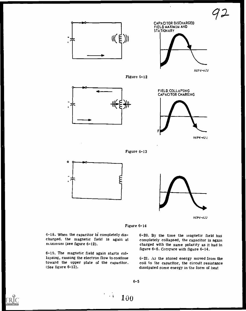
)))
Figure 6-12
*
Figure 6-13
Figure 6-14
6-18. When the capacitor is completely dis-charged. the magnetic field is again atmaximum (see figure 6-12).
6-19. The magnetic field again starts col-lapsing, causing the electron flow to continuetoward the upper plate of the capacitor.(See figure 6-13).
100
CAPACITOR DISCHARGEDFIELD MAXIMUM ANDSTATIONARY
REP4 -6:0
FIELD COLLAPSINGCAPACITOR CHARG:NG
ReP4-621
REP4 -622
6-20. By the time the magnetic field hascompletely collapsed, the capacitor is againcharged with the same polarity as it had infigure 6-6. Compare with figure 6-14.
6-2L P3 the stored energy moved from thecoil to the capacitor, the circuit resistancedissipated some energy in the form of heat
6-5

I
R.' P4 -515
Figure 6-15
LAMP10V1
Figure 6-16. Dampened Wave
so that the charge is less than in figure6-10.
6-22. If the circuit is not opened. the dis-charging and charging action will continueuntil all the energy has been dissipated asheat.
6-23. The number of times this set ofevents occurs per second is called the naturalfrequency (or resonant frequency) of thecircuit.
6-24. In practical circuits, the heat loss inthe resistance of the circuit causes eachcycle to be smaller than the previous cycle.The result is a DAMPENED wave as shownin figure 6-15.
0-25, We said earlier that the onixising forceof the tank could minintile line current. Forcurrent to flow, a difference in potentialmust exist. Picture two generators or twobatteries with a lamp connected betweenthem as in figure 6-16. In the battery clr-cult, it is easy to see that no current canflow through the lamp. No difference inpotential exists. Likewise, if two generatorsare at exactly the same frequency and theiroutputs identical, no differences in potentialcan exist, and NO CURRENT CAN FLOW.
6-26. When a tank circuit is functioning atresonance . the same condition exists. Seefigure 6-17. You will notice by examiningfigure 6-17, that at any instant along theEMF sine waves, the voltage of the generatoris almost counteracted by the voltage of thetank. The amplitude of the tank voltage willbe slightly less than that of the generator.For this reason, a minimum current willflow in tile line to replace the energy lostthrough 1 `R.
6-27. At resonance, the parallel tank offersmaximum opposition to line current. There-fore, at resonance, the parallel tank offersMAXIMUM IMPEDANCE to line current.
6-28. Recall that as frequency goes belowresonance, capacitive reactance goes up andinductive reactance goes down, similarly,as frequency goes above resonance, XCgoes down and XL goes up.
6-29. With this in mind, you can see whatwill happen to current flow in a parallelRCL circuit. If the frequency is very low,Xi. is low and XC is high, so more currentwall flow through the inductive branch. Thecircuit is then acting INDUCTIVELY.
6-6
6-30. Refer to figure 6-18. With Ea = 100Vand Xt. = 50 ohms, IL = 2 amps. With XC10 k aims, lc = .01 amp and is negligiblewhen compared with inductive current. Thiscircuit is acting INDUCTIVELY.
6-31. Refer to figure 6-19. With the fre-quency high, the reactance values arereversed. X now offers 50 ohms of oppo-sition, while XL is 10 k ohms. Most of the
101
4?-3

GENEMF
A
TANKEMF
0
Figure 6-17
UP4-518
Figure 6-18. Effect of Very Low F
current is through the capacitor. Therefore.the circuit is acting CAPACITIVELY.
6-32. With the resonant frequency applied,the tank circuit offers a very high impedanceto the generator; therefore, line currentdecreases to a minimum.
6-33. Keep in mind that with the parallelresonant circuit, the capacitive current leadsthe applied voltage by 90 °; and the inductivecurrent lags the applied voltage by 90°.These two currents are equal and opposite.When the capacitor is discharging, the dis-charge current flows through the inductor.
6-7
OCP4-516
Rspi -519
Figure 6-19. Effect of a Very High F
This stores energy in the electromagneticfield. When the magnetic field of the coilis collapsing, the resulting current flowsinto the capacitor. This stores energy inthe electrostatic field.
6-34. The tank circuit has a small amount ofresistance: the wire, internal resistance ofthe coil, and connections. This resistancedissipates energy as heat (I2R loss); so asmall amount of line current is permittedto flow. Since the line current is minimumat resonance, the impedance is maximum.This result can be seen from Ohm's Law:
Z ..g.I
lei
IV

tbapler 7
SERIES ANI) PARALLEL RESONANT CIRCUITS
7-1. In this chapter, we will first comparethe characteristics of series and parallelresonant circuits. Then, we will differentiatebetween current curves for series and forparallel RCL circuits. We will also solvefor the Q of a circuit; when given the com-ponent and frequency values. Finally, we willuse a tuned frequency response curve todetermine the bandpass and the bandwidth ofresonant circuits.
7-2. It is important that the relationshipbetween series and parallel RCL circuits beSept in mind: so we'll look at the chart belowshowing the characteristics of series andparallel resonances.
7-3. You know that figure 7-1 is a parallelRCL circuit; when IL is equal to lc, mini-mum line current will flow: and the tankcircuit will offer a high in,clance to linecurrent.
K`7-4. The object of this is not to repeatsomething you already know but to stressthese important facts; to enable you todifferentiate between an impedance curve fora series RCL circuit, and an impedancecurve for a parallel RCL circuit.
Figure 7-1
REP4-5 31
SERIES RESONANCE
.1S9Ft ,
XL = Xc
PF s 1
Z is minimum
I is maximum (line)
3andwidth depends on Q
PARALLEL RESONANCE
.159
--V-17
ri. 4 Zc
PF = I
Fr z
Z is maximum
I is minimum (line)
Bandwidth depends on Q
REP4-534
7-1
103
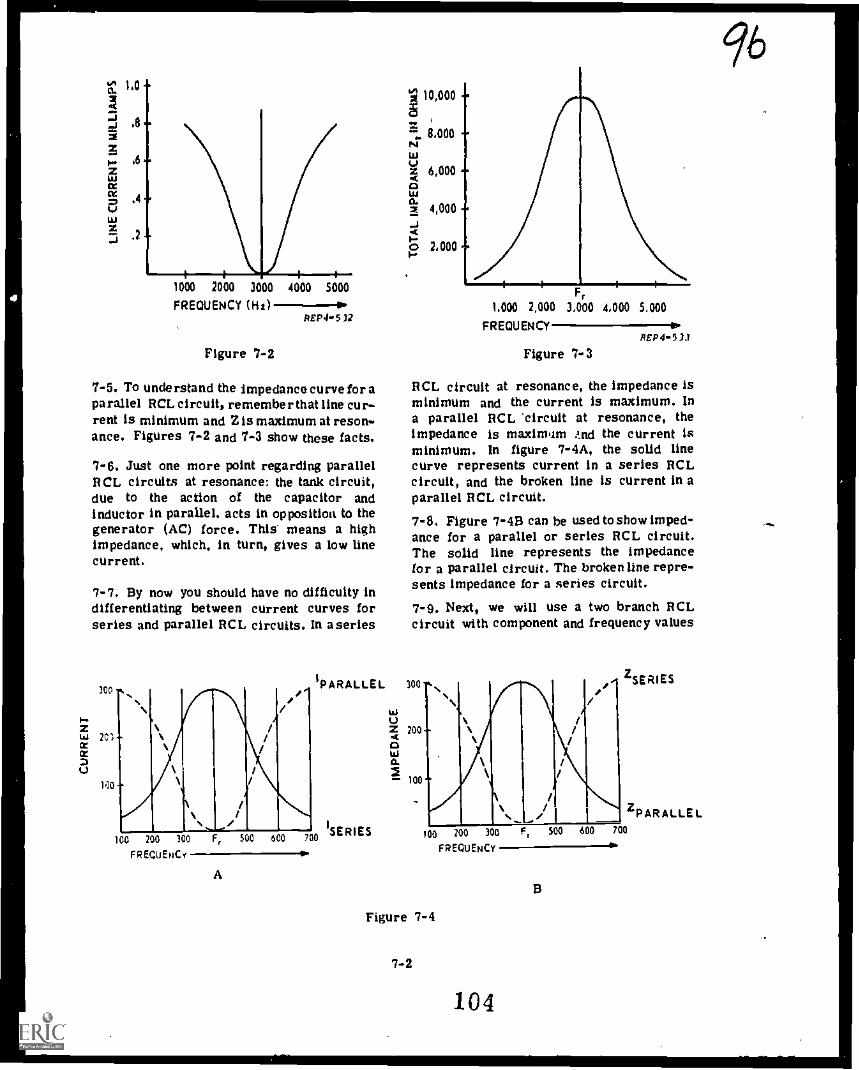
1000 2000 3000 4000 5000
FREQUENCY (HI) ---10REP4-5 12
Figure 7-2
7-5. To understand the impedance curve for aparallel RCL circuit, remember that line cur-rent is minimum and Z is maximum at reson-ance. Figures 7-2 and 7-3 show these facts.
7-6. Just one more point regarding parallelRCL circuits at resonance: the tank circuit,due to the action of the capacitor andinductor in parallel, acts in opposition to thegenerator (AC) force. This means a highimpedance, which, in turn, gives a low linecurrent.
7-7. By now you should have no difficulty indifferentiating between current curves forseries and parallel RCL circuits. In aseries
300
1-zW 2C1aaZU
MO
Ilt 10,000i:::.
NILI0.tz 6,000 -0o.2 4,000 --14o-o 2,000 -0o-
8,000 -
$i iFr
1,000 2,000 3,000 4,000 5,000
FREQUENCY-----ePEP4-531
Figure 7-3
RCL circuit at resonance, the impedance isminimum and the current is maximum. Ina parallel RCL 'circuit at resonance, theimpedance is maximum And the current isminimum. In figure 7-4A, the solid linecurve represents current in a series RCLcircuit, and the broken line is current in aparallel RCL circuit.
7-8. Figure 7-4B can be used to show imped-ance for a parallel or series RCL circuit.The solid line represents the impedancefor a parallel circuit. The broken line repre-sents impedance for a series circuit.
7-9. Next, we will use a two branch RCLcircuit with component and frequency values
/PARALLEL 100
100 200 300 F, 500 600 700/SERIES
FREQUENCY
A
wUZ 200
0wa.
- 100
--zSERIES
100 200 300
FREQUENCY
Figure 7-4
7-2
104
B
96

AO
givtn, to deft rmine the Q of the tank circuit,Q is defined for the circuit in figure 74,as the ratio of the inductive reactance tothe tank circuit series resistance. A highQ circuit is highly responsive to frequencychanges. In order to find Q, we use theformula:
XQ It (series resistance)
II is any resistance in series with the coil.
7-10. When the series resistance of theRCL circuit is quite small, the Q will belarge. Let's find the Q of the tank in figure7-5. It is a simple matter to substitute thevalues of XL and R in the formula:
XL (1000 ohms)Q - - 10R (100 ohms)
A Q of I0 or more is considered a high Q.
D
Figure 7-5
XL =10
R = Mg
REP4-5 36
7-11. When we apply the formula for Q. youcan see that the lower the resistance, thehigher the Q. Inversely, if resistance is high,the Q will be low (see figure 7-6). Animportant point to realize is that as Qdecreases. the sharpness of the curvedecreases: and as Q decreases, the angle oflead or lag decreases for any one frequencyexcept that of resonance.
977-12. The circuit of figure 7-7 shows aresistor in series with the AC generator.By examination of the circuit, you can seethat it Is now a series parallel circuit. Itis also evident that the voltage across theparallel branch no longer equals the applied
voltage but rather ER 4' Etank ' Ea
Figure '7-6
7-3
105
REP4-538
Figure 7-7

50
40
30
20
10
RESONANTFREQUENCY
10 20 30 40 50 60 70 80FREQUENCY IP
PrP4-531
Figure 7-8
7 -13. When the input frequency is variedfrom below resonance to above resonance,a voltage curve for the parallel tank canbe drawn (see figure 7-8).
7-14. Assume the generator output is 50 Vin amplitude, and its frequency may bevaried from 0 to 80 Hz. Below resonance,I C is less than andand we could draw anequivalent series circuit of a resistor and acoil. Above resonance, IL is less than lc.Now our equivalent series circuit would havea resistor and capacitor.
7-15. You can plot the voltage curves shownin figure 7-8 if you keep in mind that E,,and ER add vectorially and their sum ib50 volts. At resonance, point B, the reactivecomponents cancel, so you can add thevoltages directly. At 40 Hz, the drop acrossER is minimum,
7-16. The voltage response curve plotted infigure 7-8 can be used to determine BAND-WIDTH and BAND PASS between the halfpower points, The half power points aredefined as .707 x E ma or .707 x 50 V =x35.35 V. Mark the two 35.35 volt points onthe E.T, curve (see figure 7-9), and thendrop lines straight down to intersect thefrequency line.
7-17. To determine BANDWIDTH, find thefrequency at these two points and subtractthe lower from the higher (52 - 28 = 24).The BANDWIDTH under these assumed
50
40
Ea
30
20
10
10 20 30 40
FREQUENCY50 60 70 80
4..REP4-540
Figure 7-9
conditions is 24 Hz. BAND PASS is definedas those FREQUENCIES which cause a volt-age across the parallel circuit of .707 xE m (31.35 V) or more. In this case theaxbandpass is from 28 to 52 Hz.
7-18. An impedance curve may also be usedto determine bandwidth and bandpass. Seefigure 7-10.
7-19. In this method, we take .707 timesZ MAXIMUM to establish a Lind through thecurve at points A and B. By dropping linesdown from these points to the frequencyreference line, we can determine the band-pass to be from 1200 Hz to 2200 Hz. Thebandwidth would be the difference between1 200 and 2200 Hz or 1000 Hz.
7-20. The 3-branch parallel resonant circuitdiffers from the 2-branch in the number of
7-4
MAXIMUM
12
MINIMUM
.707
108
1200
Figure 7-10
2200 3000REP4-541
q

REP4..542
Figure 7-11
Figure 7-12
'1R
REPO -543
Given
Ea 25 V
Xc 51 ohms
XL 51 ohms
F 1.2 kHz
R 100 ohms
Find
IC =
IL
=
Itank 2
Iline 2.-
99
possible current paths. A 3-branch cir-cuit configuration is shown in figure 7-11. SolutionThe combination of L and C in figure 7-11form a parallel resonant circuit. Notice that Determine lc:there is no resistance shown in series withthe inductive branch. At resonance, thevector diagram of the branch currents will Ea 25 Vbe as shown in figure 7-12. C XC 5IQ
7-21. U the reactive currents (IC and IL)are equal, the circuit will appear to be a Determine IL:purely resistive circuit. It will have animpedance value that is equal to R. Thecircuit shown in figure 7-13 may be solved Eafor its currents, impedance, circuit Q and xL
25 V a:.= 490 mA &If
51Q L9S1other characteristics in the following manner:
ATP4 -544
Determine I.Ea 25 V isn
250 mAR R 100Q L();
7-22. To determine the current drawn fromFigure 7-13 the source (line current), insure all currents
_7-5
107

IC 490ilin
IR 250mA 'LINEOP,
or.
11 wonQ t
11
It _- 490 mA AtP4..545 7-25. Notice that the formula Q =X
isL
just opposite of the formula used in the 2-Figure 7-14 branch parallel resonant circuit of figure
7-5.are in vector form and add, as in figure7-14. Since the reactive currents cancel,the line current is equal to the current drawnby the resistive component. At resonance:
Iline = IR
7-23. Since the circulating current of theresonant tank is the same for either reactivecomponent; then tank current may be foundby determining current flow through thecapacitor or inductor.
E a 25 V/tank
._X
C51 Q
a 490 mA
At resonance:
I tank 2 IC 2 IL
7-24. The LC combination in figure 7-13forms an ideal parallel resonant network.The impedance of the tank circuit underthese conditions may be considered to beinfinite. The equivalent resistance offeredto the source by the parallel circuit com-posed of an infinite impedance in parallelwith a resistance is equal to the value ofthe resistance. The circuit impedance canbe determined in the following manner:
EZ 25VV=a--Iline 0.25 A
= 100 ohms
To determine the value of Q for figure7-13 use the formula:
Q'tank 490 niA_
250 inAI. - 1.96
7-26. The 3-branch RCL circuits have theterms bandwidth and selectivity applied tothem. The formula for bandwidth undergoesslight modification: i.e., it will not be thesame as for the 2-branch circuit. In the3-branch circuits parallel resonant circuit
fr x XLbandwidth equals BW - .
7-6
7-27. If the parallel resistance is increased,the line current goes down. As the shuntingresistance approaches infinity, the line cur-rent approaches zero. As resistance isincreased, the bandwidth becomes narrower,and the selectivity increases. Therefore, itcan be seen how regulation of the handwidthmay be accomplished by variation of theshunt, or "swamping" resistor. The inverserelationship between resistance and band-width may be seen by examination of equa-tions above and the curves in figure 7-15.
HIGH R
108
Figure 7- Is
PE424-.54e
/CA/

Chapter $
PARAMETER CHANGES IN PARALLEL RESONANT CIRCUITS
ri-1, In this section of the text you will studythe infects of increasing the applied fre-quency, resistance, capacitance, or induc-tance in a parallel circuit. We will changeonly one of these factors at a time and usecharts and vectors to show the effects ofthese changes,
8-2. At Resonance
8-3. At resonance the inductive reactance(XL) and the capacitive reactance (XC) areequal and therefore cancel each other. Thecurrent in the CAPACITIVE branch is equalto:
Ealc Xc
Likewise, the INDUCTIVE branch:
EaIL
-XL8-4. Currents in both branches are equal andare shown as vectors in figure 8-1A. Thecurrent flow through the resistor Is the totalcurrent (It) in the circuit. Because IL andIC are 180 degrees out of phase and equal invalue, they cancel and do not flow through theresistor.
8-5. At resonance the resistor current andtotal current are one and the same. Therewill be NO phase angle difference - thephase angle is zero. Remer n'3er, this iswhen the circuit is at resonance.
8-6. Now, let us INCREASE frequency,keeping in mind the formulas:
XLEa
2/UL and IL =X
Ea1
X = and =---C 2 WIC C X
As frequency goes higher, XC has toDECREASE: this means that lc will
IC
IL
8-1
/O(
INCREASE. Also as frequency goes higher,X L has to INCREASE and IL will DECREASE.There will be less IL to subtract from lc,and It will INCREASE. It2 * Ift2 (IC IL)2.The vector diagram in figure 8-113 illustratesthese facts and Table 8 -I shows the results.Since it is evident that current has increased,what must have happened to impedance? Thetotal OPPOSITION to current has
EDECREASED. Z = a . Again, referring to
tthe vector diagram of figure 8-IB, noticethat total current is NOT in phase with theresistor current. Total current is leadingthe resistor current by some angle. Thephase angle has increased from zero. As theangle increases, the cosine (power factor)decreases.
8-7. Now, assume that resistance increasesand find out what effect this has on current.
It
IR
109
A
ec 4
Figure 8-1
REP4 -375

Table 8-1
STARTING AT RESONANCE
Increase In Current Will Impedance Will Phase Angle Will
Frequency Increase Decrease Increase
Resistance Decrease Increase Not Change
Capacitance Increase Decrease Increase
Inductance Increase Decrease Increase.
EaRemember that: IR 2Ft- and at resonance
IR = It. Now you can see that an INCREASEin resistance INCREASES impedance, whichin turn DECREASES current flow. At reso-nance the phase angle does not changebecause IL and lc have not changed.
8-8. Now increase capacitance. To deter-mine the results remember that:
1Ea
X 2 and I 2C 27fIC C X
C
8-9. When there is an INCREASE in C, wehave a DECREASE in XC. This causes anINCREASE in IC. Because IL no longercancels IC ' there is an INCREASE in It. Seefigure 8 -lB. What happens to phase angle?It increases the same as it did when weincreased frequency.
8-10. When inductance INCREASES, theinductive reactance INCREASES, becauseXt. = 27r fL. When this happens, ILDECREASES and no longer cancels IC. Totalcurrent INCREASES and impedanceDECREASES. As the inductance is IN-CREASED, the phase angle will INCREASE.
8-11, We have now analyzed the effects of anincrease in frequency, resistance, capa-citance, and inductance starting AT RESO-NANCE in a parallel RCL circuit.
8-12. Below Resonance
A
Ic A
1 *LC
B
A
1 *L
Figure 8-2
D
REP4- 376
8-13. Notice that BELOW RESONANCE XLis smaller than Xc. Because XL is smaller,the vector for IL is larger,than the vectorfor lc. See figure 8-2A. Vote that It lagsIR and the circuit acts inductively.
8-14. If we were to increase frequency, thenXL increases and Xc woulddecrease. There-fore, IL would decrease and 1C will increase.
8-2
110
P ?-
\

Table 8-2
STARTING BELOW RESONANCE
/613
Increase In Current Will Impedance Will Phase Angle Will
Frequency Decrease Increase Decrease
Resistance Decrease Increase Increase
Capacitance Decrease Increase Decrease
_Inductance
IDecrease Increase Decrease
As the frequency approaches resonance theincrease in IC will cancel more of ILand It will decrease. See figure 6-2B. Thephase angle has become less because thetotal reactive current has decreased (1L-10.The It vector has moved closer to the appiiedvoltage vector.
8-15. Now increase resistance while oper-ating below resonance. The deerease in 1when combined with the reactive currenwill decrease total current. See figure 8-2C.
EImpedance must have increased (Z = -r ).
tWith the increase in resistance, the Itvector will move closer to the reactivevector and the phase angle will INCREASE.
8-16. What happens when we increase capa-citance while operating below resonance?The formula for capacitive reactance justabout answers our question let's look at it:
1X , .T.
C 2-ir fC
When C goes up, XC goes down. When XCgoes down, there is less opposition to currentflow and IC goes up. Remember we havenot changed frequency, so IL will not change.Now 1C will cancel more of IL and the reac-tive current will decrease. When you combinethe IR with the difference in the reactivecurrent, you find that It has decreased.It2 = /R2 + (IL - 1c)2 . A decrease in Itmeans that impedance has increased. The It
vector has moved closer to the Ea vector.The phase angle has decreased.
8-17. The last one is an increase ofinductance. XL = 2 7e fL. As L goes up, XLhas to go up, and IL has to decrease. Imped-ance is increasing, and it is decreasing,and moving closer to Ea; therefore, the phaseangle is decreasing. See figure 8-2D.
8-18. Table 8-2 summarizes the changes thatoccur for increases infrequency, resistance,capacitance, and inductance in a circuit thatis operating below resonance.
8-19. Above Resonance
8-20. The last table we will discuss starts atan ABOVE RESONANCE condition. We will gothrough the same procedure to determine theeffects of an INCREASE infrequency, resist-ance, inductance, or capacitance. Refer tofigure 8-3.
8-3
111
A
lc
0
IL'
Figure 8-3
Ilt
B
REP4-377

8-21. Above resonance simply means thatIC is greater than IL. Again the capacitivereactance formula and the inductive reac-tance formulas must be kept in mind:
=
Eaand IX
C 211 fC C XC
XL = 2TrfLEa
and I r.L
X L
8-22. If you have an increase in frequency,Xc will decrease and XL will increase;IC will increase and IL will decrease. Thedifference between lc and IL will increaseand when combined with IR will increasetotal current. When there is an increasein total current, the impedance must havedecreased. When lc increases the It vectorwill move closer to the if vector. When thishappens, the phase angle increases.
8-23. With an increase in resistance, we havea decrease in total current and an increasein impedance.
8-24. When we start above resonance andincrease capacitance, we again apply theformulas:
1Ea
X .. and I =C 27f fC C
As capacitance goes up, Xc decreases andIC increases. An increase in IC will increaseIt. As this takes place, the phase angle isincreasing. To sum up what happens whenthe capacitance is increased: total currentincreased. impedance decreased, and phaseangle increased.
8-25. When there is an increase in inductancewhile above resonance, you can see by theformula XL = 211fL that the inductive reac-tance has to increase. This causes the induc-tive current. to decrease. IL will cancelless of IC and increases total reactive cur-rent.rent. It& = IR2 + (IL - Ic)2. This being thecase, the total impedance must have
Edecreased. Z = . The It vector movesIt
closer to the IC vector and the phase angle
increases, = SinIC
al,t
8-26. Table 8-3 summarizes the changesthat occur for increases in frequency, resis-tance, capacitance, and inductance in a cir-cuit that is operating above resonance.
8-27. This lesson combines several factsthat you already know. For example, the factthat when opposition to current flow becomesless. then current must increase; or, whencurrent increases, impedance must havedecreased (providing voltage remains thesame). You also found that the use of vectorsis an easy way to determine just what takesplace when there is a change in frequency,resistance, capacitance, or inductance. So,if you have a question about the results,construct the vectors.
8-28. Tables 8-1, 8-2 and 8-3 are forexplanation purposes, DO NOT MEMORIZETHEM. Instead, use vectors, formula and/orfigure 8-4 to analyze the circuit.
FREQUENCYPEP4-2008
Figure 8-4
ana
4
8-4 I
112

,
,
:Table 8-314 kl .
STARTING ABOVE RESONANCE
Increase in Current Will Impedance Will Phase Angle Will
Frequency Increase Decrease Increase
Resistance Dec. ease Increase Increase
Capacitance Increase Decrease Increase
Inductance Increase Decrease Increase
8-5
113

Chapter 0
TRANSIENTS
0-1. The function of many electronic circuitsis waveshaping for timing or control. Thesewaveshaping circuits must produce a varietyof nonsinusoidal waveforms, such as squarewaves, sawtooth waves, trapezoidal waves,rectangular waves, and peaked waves ortriggers (figure 9-1), whose duration andamplitude can be controlled with respect toTIME . Proper operation of a waveshapingcircuit depends upon the circuit's responseto a transient voltage or current. This chap-ter discusses transients in RC and Rtseriescircuits.
9-2. A TRANSIENT voltage (or current) isthe rapid change of voltage (or current)from one steady state to another steadystate. The time allowed for the transientaction is called the TRANSIENT INTERVAL.The waveshape may be observed as a graphby plotting amplitude relative to time.
9-3. A simple capacitor consists of twoplates separated by insulating material knownas dielectric. CAPACITANCE is the charac-teristic of a circuit or component which
/D6
enables it to store an electrical charge.Charges are developed when electrons aremoved from one place to another resultingin an excess of negative charge at one pointand a deficiency of negative charge at theother. Electrons cannot be moved instan-taneously. All capacitors take time to charge.The time required for a capacitor to chargedepends on the amount of resistance throughwhich the charging current flows, and on thesize of the capacitor.
9-4. Figure 9-2 shows a simple series cir-cuit with a battery, resistor, capacitor, andswitch. When the switch is closed, the seriesbattery voltage is applied across the RCcircuit. Since C has no charge at the firstinstant, the initial charging is limited onlyby the size of R. The charging current flowinginto C starts to accumulate. The accumulatingcharge appears as a voltage drop across C.
9-5. As the voltage across the capacitorincreases, the voltage across the resistordecreases. It is the voltage across theresistor and the amount of resistance that
m m .1. - - -Ov - - .- -
- - - .-OV OV
SOUARE WAVE -SAWTOOTH WAVE TRAPEZOIDAL WAVE RECTANGULARITEC7ANGULARTAV-E TRIGGERS- - - -
Figure 9-1
Sw
Figure 9-2
9-1
-
REP4 .41
114
REP4-00

&term Inc the charging current. The resistorvalue affects the charging current and, there-fore, the time required to charge the capa-citor. Capacitor size also affects chargingtime. The larger the capacitor, the moretirne required to charge it to a given voltage.
0-6, We have said that resistance affects thecharging time of a capacitor. In addition,the value of the capacitor affected the chargingtime. You may remember from an earlierlesson that the relationship between charge,voltage, and capacitance was expressed asQ = EC. According to this equation if wehold E constant, and increase capacitance weincrease the number of electrons requiredto charge the capacitor to that given voltage.Since more electrons are required to chargea larger capacitor; and, since the rate ofthe charging current is determined by theapppied voltage and circuit resistance, it isobvious that more time is required to chargea larger capacitor. The reverse is true ifcapacitance is decreased.
9-7. The applied voltage does not affect thetime required to charge a capacitor. When-ever the applied voltage changes, the chargingcurrent changes a proportional amount, andthe charging time is not affected.
9-8. The amount of resistance and capa-citance are the only factors which determinethe time required for a capacitor to chargeto a given percentage of the applied voltage.The same holds true for the time requiredfor a capacitor to discharge. Since time,resistance, and capacitance are related, wecan express this relationship mathematicallyas TC= RxC where TC is in seconds, R isin ohms, and C is in farads, The product ofR times C is called a TIME CONSTANT.
9-9. A time constant in an RC circuit is thetime it would take a capacitor to charge tothe applied voltage IF IT CONTINUED TOCHARGE AT ITS INITIAL RATE. However,as the capacitor charges, the charging currentdecreases, and the rate of charge decreases.The result is that a capacitor only chargesto about 63% of the applied voltage in onetime constant (R x C). Because of this, ATIME CONSTANT IS DEFINED AS THE TIME
REQUIRED FOR A CAPACITOR TOCHARGETO 63% OF THE APPLIED VOLTAGE.
9-10. During the first time Constant, thecapacitor will charge to 93% of the appliedvoltage. Since this capacitor voltage thenopposes the applied voltage, the differencebetween the applied and capacitor voltage(100% - 63% = 37%) is termed the AVAIL-ABLE voltage, During the second time con-stant, the capacitor will charge to 63% ofthe AVAILABLE voltage , This AVAILABLEvoltage is 37% of the applied, so 37% x 63%23.3%. To find what percentage of the appliedvoltage the capacitor has charged, simplyadd the percentages of these two charges,so 63% + 23.3% = 86.3%. Repeating thisprocess we find the capacitor charged tothe following levels for the following:
Third time constant -
13.7% x 63.0% = 8.6%8.6% + 86.3% = 94.9%
Fourth time constant -
5.1% x 63.0% = 3.2%3.2% + 94.9% = 98.1%
Fifth time constant -
1.9 %x 63.0%= 1.2%1.2% + 98.1% = 99.3%
9-11. Theoretically, the capacitor will neveracquire a full charge. However, the dif-ference between the voltage applied and thecapacitor charge is negligible after fivetime constants. Therefore, it is assumedthat A CAPACITOR IS FULLY CHARGEDAFTER FIVE TIME CONSTANTS (5 TC).
9-12. Keeping the same values of R and C,the capacitor will always charge fully in thesame period of time regardless of the magni-tude of the applied voltage. Applied voltagewill, however, determine the RATE of charge.By RATE we mean the rapidity with whichthe voltage across the capacitor builds up.It is this rate change that enables a capa-citor to fully charge in the same periodof time despite variations of applied voltage.
9-2
115

100
90
00
70
60
30
40
30
to
10
0.3 2 3
IIIIIMMIN NS:iiii11111e:raiiim---iiiLMIIIIIIIIII III NiliiiMii IBM% M RIIIIIIIIIIE EN OM1111111111 I1111111111111111111111/4IIIINIIIIPAIIiiii0iirAiN111111V/1i111111M111111111r/ligillIIIIKIIIIIM11111111111W1111M11110ILIUM'111111111111111111111rimili
EllII1I
CURVE RC CIRCUIT LR CIRCUIT
A
ION
PCAHC1 ;7t:: VOLTAGE rEDSITTOORR VCOULRTRAEGNETOONR
BusLo-uP
IB
I
iSreimaRRar.TAG E
RESISTOR VOLTAGE OR
CHARGE OR DISCHARGE N
IRNEDOTTOOR" VCOULVAEGNEY OONR
DECAY
INDUCTOR VOLTAGE ONBUILD -UP OR DECAY
0. 1EliN..-a.mom.Immilms. iiiiiiirrammIN.
0.3 2 3
TIME IN TIME CONSTANTS
UNIVERSAL EXPONENTIAL CURVES FOR RC AND LR CIRCUITS
Figure 9-3
The only way the capacitor's full charge timecan be changed is by varying the time constant.
9-13. The opposite of the above is also true.A capacitor will discharge 63% during one timeconstant, 86.3% in two, 94.9% in three, 98.1%in four, and fully discharge in five timeconstants. Variations in the magnitude of volt-age to which the capacitor is charged will onlyaffect the RATE of discharge. Its dischargeTime can be changed only by varying the timeconstant.9-14. Remember: Variations in applied volt-age can change only the RATE a capacitorcharges or discharges. Despite any suchvariations, a capacitor will always charge to63% of the applied voltage or discharge alike percentage during one time constant. Bythe same token, a capacitor will always fullycharge or discharge in five time constants.
9-15. Since a capacitor charges or dis-charges 63% of the AVAILABLE voltageduring each time constant, a chart showingthis change in percentage of voltage versusnumber of time constants can be plottedand used for all series RC circuits. Sucha chart has been prepared for you and itis known as a UNIVERSAL TIME CONSTANTCHART. By knowing how to read the chart,you can determine the voltage across anycomponent and the circuit current at anyinstant. Likewise, you will be able to deter-mine the time required for the circuit cur-rent (or the voltage across a component) toreach a given value.
9-16. A UNIVERSAL TIME CONSTANTCHART is shown in figure 9-3. Notice thatthe horizontal axis indicates the number oftime constants and that the vertical axis
9-3.
116

indicates the PERCENT of voltage or current.The exponential curves, "A" and "D" wereplotted by calculating the instantaneous capacifor voltage at many points during charge anddischarge and connecting the points with asmooth curve. At the end of five time con-.stante, the "A" curve is so near 100% weconsider the capacitor fully charged and the"B" curve is so near 0% that we considerthe capacitor fully discharged.
9-17. Before using the chart, we mustconsider one more time element - the timethat the capacitor will be allowed to chargeor discharge. The numbers along the hori-zontal axis of the chart represent the numberof time constants (R x C) in the time allowed(t) for the charge or discharge of the capa-citor. Mathematically, the number of timeconstants equals the time allowed for chargeor discharge divided by the time constantof the circuit. As an equation:
t#T C = .hce
where
4TC = number of time constants
t = time allowed for charge or discharge(seconds)
R T. the resistance of the circuit (ohms)
C = the capacitance of the circuit (farads)
9-18. For RC circuits on charge, the percentof available voltage to which the capacitor hascharged is read on the "A" curve. The per-cent of available voltage across the resistorand the percent of maximum circuit currentare read on the "B" curve. Note that whenthe reading is taken from the "B" curve thatyou are starting with 100%, so that the per-centage reading is that percentage of voltageREMAINING across the components or the pe r-centage of current remaining in the circuit.If in one time constant the voltage decreases63%, then 37% remains acrossthe component.
9-19. The functions of the "A" and "B"curves as used in RC circuits are summarizedin the chart shown in figure 9-4.
9-4
A CURVE
EC on capacitor chore.
B CURVE
ER on capacitor charge
I on capacitor charge
Econ capacitor discharge
ER on capacitor discharge
I on capacitor discharge
REP4-9 .t
Figure 9-4
9-'40. One efficient way to learn to use the timeconstant chart is by solving problems.Transient problems fall into three generalcategories:
1. Determining circuit current and com-ponent voltages after a given time.
2. Determining the time required for circult current and component voltages to reacha given value.
3. Determining component values requiredfor the circuit current and component voltagesto reach a given value in a given time.
9-21. PROBLEM 1
9-22. Using the circuit values of figure9-5, compute the time constant, determine
I E0
40V
0SW
117
Figure 9-5
SKo
03 UF
REP4-94

the percent of 'Marge on the Capacitor, thevoltages across the capacitor and resistor,and circuit current 1200 microseconds afterthe switch is closed.
Step 1: List what is given and what is tohe found.
Given: Ea = 40 volts
R = 5 k ohms
C = 0.1 microfarads
t = 1200 microseconds
Find:Time Constant a
4TC =
% of Charge =
EC =
ER =
.1=1M.1111=111
... ....ri ..wer..
1=
Step 2: Compute the time constant.
TC = Et x C
=5 x 103 x.1 x 10-6
= .5 x 10-3
= 500 x 10-6 seconds
Step 3: Compute the number of time constantsin the time allowed.
t#TC = Trtc
1200 x 10-6-500 x 10-6
= 2.4
Step 4: Locate 2.4 time constants on thehorizontal axis of the time constant chart.Move up the 2.4 line until it intersects curve
llO"A," From the intersection, read left to thevertical axis of the time constant chart anddetermine the percent of charge (voltage)across the capacitor. For this example youwill find this percentage to be 01%,
Step 5: Calculate the capacitor voltage.
EC= 91% x Ea
=.91 x 40V
a 36.4 volts
Step 6; Calculate resistor voltage.
ER E - ER a C
= 40 V - 36.4 V
= 3.6 volts
Step 7: Calculate circuit current. Sincecurrent is the same at all points in a seriescircuit, resistor current is circuit current.
3.6V5 k ohms
=.72 mA
9-23. In the preceding problem we used thetime constant chart to determine the circuitcurrent and component voltages after agiventime. We are now going to use the timeconstant chart to determine the number oftime constants required for the capacitorvoltage to reach a given value of the availablevoltage.
9-24. PROBLEM 2
9-25. Use the circuit values of figure9-6. The capacitor is uncharged. After theswitch is closed, how many time constantsare required for the capacitor voltage torise to 30 volts?
9-5
ITS

i Ea
50V
SW
100K fl
.2uF
TREP4'95
Figure 9-6
PROCEDURE PROCEDURE
Step 1: List what is given and what is to Step 1. List what is given and what is to
Figure 9-7NIP4-96
be found.
Given: Ea = 50 volts
R = 100 k ohms
C = .2 microfarads
Find: Number of time constants requiredfor EC to reach 30V.
Step 2: Determine the percentage of theavailable voltage that will be across thecapacitor by dividing the capacito r voltage bythe available voltage, and multiply the quo- Find:tient by 100.
be found.
Given:
30-
Vcri = .6 x 100 = 60%
Ea = 50 V
Ec = 50 V
ER = 0 V
R = 40 k ohms
t = 130 microseconds
C = 0.0025 microfarads
OTC =
% of Discharge =
EC
=
Step 3: Using the time constant chart, moveup the vertical axis until you reach 60%. ER =
Since the capacitor was charging, move totheright along the 60 percent line unitl you inter- 1=sect the "A" curve. At the intersection readdown to the horizontal axis to find the number Step 2: Determine the number of time con-of time constants. For this problem, youwill stants in the time allowed.find the number of time constants to be .9.
9-26. PROBLEM 3
9-27. In figure 9-7 switch 1 is closed, untilthe capacitor is charged to the availablevoltage, .then opened. Find the percent ofdischarge of the capacitor, capacitor voltage,resistor voltage, and circuit current 130
microseconds after switch 2 is closed.
9-6
OTCt = (130 x 10
6)
R x C(40 x 103) (0.0025 x 10⁻⁶)
= 1.3
Step 3: Locate 1.3 time constants on thehorizontal axis of the time constant chart. .
On discharge, the capacitor voltage is read
119
ME.

on the "0" curve, so move up the 1.3 timoconstant line until you intersect the "B"Curve.
Step 4: At the intersection of the 1.3 timeconstant line and the "B" curve, read tothe left to determine the percentage ofvoltage retraining on the capacitor. Thepercentage remaining is 27.5 percent.
Step 5: Determine the remaining capacitorvoltage.
EC= 50 V x .275
= 13.75 V
Step 6: Since the capacitor is acting as apower supply during discharge, the resistorvoltage is equal to the capacitor voltage or13.75 V.
Step 7: Calculate circuit current. As the cir-cuit is a series circuit, the resistor currentwill be the circuit current.
l= ER_ 13.75 V .344 mA-- -A
Step 8: Determine the percent of dischargeof the capacitor. Locate 1.3 time constantson the chart. On the "A" curve read thepercent of discharge as 72.5%.
9-2$. PROBLEM 4
9-29. Find the resistance of R in figure9-8 if the capacitor charges to 50 voltsin 1000 microseconds.
CSW
Figure 9-8
01U1
REP4-97
PROCEDURE:
Step 1: List what is given and what is tobe found.
Given: Ea 2, 100 V
EC a 50 V
t 2 1000 microseconds
C = 0.01 microfarads
Find: R =
Step 2: Find what percentage of the availablevoltage is across the capacitor by dividingth capacitor voltage by the available voltageand multiplying by 100.
.. 50 v: OUT X MO = 50%
Step 3: Use the time constant chart to findthe number of time constants required forthe capacitor to charge to 50% of the appliedvoltage. Move up the vertical axis of thetime constant chart to the 50% mark thenmove right to the intersection of the "A"curve. From this point, read down to thehorizontal axis. The number of time con-stants is 0.7.
Step 4: Use the equation for the number oftime constants to solve for R.
transposing:
substituting:
R0.7 x (0.01 x lo-6)
OTC =t
R x C
tR = ir1=Ct
moo x 10 6)
9-30 Deleted.
9-31. Deleted.
9-7
120
- 142.8 k ohms

REP4100
Figure 9-9
9-32. Deleted.
9-33. Deleted.
9-34. LR Problems
9-35. Just as the voltage across a capacitor,due to the charge in the capacitor, is inopposition to the applied voltage, the voltageinduced in an inductor, resulting from achange in current through the inductor, is inopposition to the applied voltage.
9-36. In an RL circuit, the current throughthe inductor, which is proportional to theenergy stored in the magnetic field, cannotchange instantaneously with a change in ap-plied voltage.
9-37. The circuit in figure 9-9 is assumed tohave no resistance. When the switch is closed,current starts to flow, causing an expandingmagnetic field which Induces a n opposing EMF.With no resistance in the circuit, currentwillincrease at a rate which will cause the inducedvoltage to equal the applied voltage. The cur-rent must increase at a constant rate if aconstant voltage is to be induced.
9-38. Unlike current rift in a purelyinductive circuit, the resistance in a seriesLR circuit prevents a linear rise in current.See figure 9-11. As the current increases,an increasing voltage drop across the resistorproduces a decreasing voltage drop across thecoil. The transient current in an LR circuitincreases at a CONTINUALLY DECREASINGRATE until the rate of change becomes zero.
9-8
tt2
g.
INDUCED VOLTAGE... . I Milmb lilI .01.
TIME sox
Figure 9-10
REP4101
The rate of current change becomes zero whenthe current reaches its maximum value andall of the applied voltage is dropped acrossthe resistor. The "A" curve of the universaltime constant chart (figure 9-12)may be usedto determine current build-up inLR circuits.Since the current through and the voltageacross a resistor are in phase, resistorvoltage on build-up is also shown by the"A" curve. The inductor acts as an opencircuit at the first instant a voltage isapplied; therefore, on build-up, the inductorvoltage is read on the "B" curve.
9-39. The inductor acts as the powersource during the decay of the electromag-netic field; therefore, during decay, the cur-rent, resistor voltage, and inductor voltageare read on the "B" curve. Figure 9-13summarizes this action.
9-40. Having established the relationshipof the "A" and "B" curves of the universal
tsxr-oom
..INDUCED VOLTAGE
%.%. .7 .---------'.....
-.,
121
TIME P.
Figure 9-11
REP4-101
/13

0,3 1 2 3 4 3
.1111111111
mummies6.111iIIIIIPM
0111111M140
"III1M111
24)1runomi
3IIIIIIIIIM1111111W
IIIEITIIII
11111111MINI:1-6--E
1111111111
1101111111.
111111111ln
semEN NM MEI.
II
mm KMMI CURVE RC CIRCUIT LR CIRCUIT
M11011M111111M1111111
IllinligillIHRII11101111,111111
1E1111111
E,
ICI
I A
IB
I1
AC IN V C" A "CAPACITOR 'DAICINTrAR VOLTAGE
BUILD-UP
CAPACITOR VOLTAGEOH DISCHARGE
RESISTOR VOLTAGE OREgta::DISCHARGE
N
INDUCTOR CURRENT ORRESISTOR VOLTAGE ONDECAY
INDUCTOR VOGBUILD-UP OR ONT
OM1mmuuuus nag MB NEummi moon E1111111111 IiiriallPionlmol
0.S 2 3
TIME IN TIME CONSTANTS
UNIVERSAL EXPONENTIAL CURVES FOR RC AND LR CIRCUITS
Figure 9-12
time constant chart to the transient responseof an LR circuit, let us examine the twofactors controlling the transient response:(1) inductance and (2) resistance.
9-41. If the inductance is madelarger, therewill be more opposition to a CHANGE incurrent flow. It will take longer for the cur-rent to reach its maximum value. Therefore,the TIME for current build-up is DIRECTLYPROPORTIONAL TO THE AMOUNT OFINDUCTANCE.
9-42. If the resistance is made larger, themaximum value of current will be less. Ifthe maximum value of current is less, thetime required to reach maximum will alsobe less. Therefore, the TIME for currentbuild-up is INVERSELY PROPORTIONAL TOTHE AMOUNT OF RESISTANCE.
122
9-9
4
A CURVE
ER on field buildup
I on field buildup
B CURVE
EL on field buildupEL on field collapse
ER an field collapse
I on field collapse
REP4-106
Figure 9-13
S

9-43. The time Is proportional to L dividedby It and is called a TIME CONSTANT. Inequation form:
where
TC a time for one time constant in seconds.L 2 inductance in henriesR = resistance in ohms
9-44. In one time constant the current willbuild up to 83% of the maximum current.At the end of two time constants, currentwill have reached 86% of its maximum value.The current rise in the LR circuit is com-parable to the rise of capacitor voltage In anRC circuit, and current is considered to reachits maximum value in five time constants.Likewise, the current is considered to reachzero in five time constants when the electo-magnetic field is allowed to decay.
9-45. Having established the time of onetime constant, we must now consider the timeallowed for the current to build up or decay.Remember that the numbers along the hori-zontal axis of the time constant chart repre-sent the number of time constants allowed forthe current build-up or decay. As an equation:
#TC =L71-I
simplified:
4TC =-L--Rxt
#TC number of time constants
t = time allowed for build-up or decay(seconds)
R = the resistance of the circuit (ohms)
L = the inductance of the circuit (henries)
9-46. Again we will use problem solving toapply the universal time constant chart toLR transient circuits.
9-10
9-47. PROBLEM 1
9-48. Find the percent of current build-up, the value of the current, the resistorvoltage, and the inductor voltage, 2800 micro-seconds after the switch is closed in figure9-14.
PROCEDURE
Step 1: Determine what is given and what isto be found.
Given:
Find:
Ea = 50 V
L -= 10 H
R a 10 k ohms
t = 2800 microseconds
#TC -
% of I ....
Imax=
I=
ER =
EL
Step 2: Find the number of time constantsin the time allowed.
x t4TC 3
R
..12I OKo
1.I Oli
REP4-102
Figure 9-14
123
1/

.111=......
(10 x 103) (2800 x 10-8)10
= 2,8
Step 3: Using the time constant chart, go tothe 2.8 time constant mark and then move upto the intersection of the "A" curve. Readleft to the vertical axis to find the percent-age of current build-up, which is 94% ofmaximum.
Step 4: Since the maximum current will bereached when all the available voltage isacross the resistor, the maximum currentmay be calculated by Ohm's Law where:
Ea
max --ir50V
-Mc S1
= 5 mA
Step 5: Find what value of current is 94%of 5 mA. This will be the current at the endof 2800 microseconds.
1 = .94 x 5 mA = 4.7 mA
Step 6: Calculate the voltage across theresistor at the end of 2800 microsecondsby Ohm's Law.
ER
= 1 x R
= (4.7 x 10⁻³) (10 x 103)
= 47 V
Step 7: Calculate the voltage across the induc-tor at the end of 2800 microseseconds byKirchhoff's Law.
EL = Ea - ER
= 50 V - 47 V
= 3V
mamgmm........._....... ,..".
A
REP4-103
Figure 9-15
9-49. PROBLEM 2
9-50. ln the figure 9-15, 1200 microsecondsafter the switch is moved from position "A"to position "B" the current will have decayedby what percent?
Step 1: List what is given and what is to befound.
Given: Ea = 75 V
R=10k sl
L = 34 H
t = 1200 microseconds
Find: Percent of current decay.
Step 2: Find the number of time constantsin the time allowed.
Rxt#TC = --L,
J10 x 103) (1200 x 10-8)34
= .35
Step 3. Determine the percent of currentdecay. Locate .35 time constants on thechart. Move up to interect the "B" curve.Move left and read 70%. The percent ofcurrent decay is 30. (100% - 70% = 30%t
9-51. PROBLEM 3
9-52. ln figure 9-16, the inductor voltage is40 V, 1500 microseconds after the switch

Ea
=100V25H
REP4-104
Figure 9-16
is closed. What is the ohmic value of theresistor?
PROCEDURE
Step 1: List what is given and what is to befound.
Given: Ea = 100 V
EL = 40 V
L = 25 II
t = 1500 microswconds
Find: R =
Step 2: Find what percentage of the availablevoltage is representedby the inductor voltage.
A
EL 40Vit -- x 100 0 40%rt: 100 V
Step 3: Find the number of time constantsrequired for the inductor voltage to changefrom 100 V to 40 V. Move up the verticalaxis of the time constant chart to the 4096mark and then move right to the "B" curve.Read down to the horizontal axis to findthe number Of time constants, 0.94.
Step 4: Use the equation for number of timeconstants to solve for the resistance.
x T1/TC =
R1--transposing:
ftTC x LR = t
(.94) (25)
1500 x 10-6
= 15.7 k CI
9-53. Deleted.
9-54. Figure 9-17A is a simple square wavegenerator. Switching from A to B then backto A in rapid succession will produce anoutput (figure 9-17B) that goes from OVto 100V at the rate of switching. At time
Figure 9-17
9-12
8
Ova1I
10
1
1I
t3
1
1.t4
1
1*
t1
1
1
t2
I
1.15
125
REPO -111
2/
...
am.
k
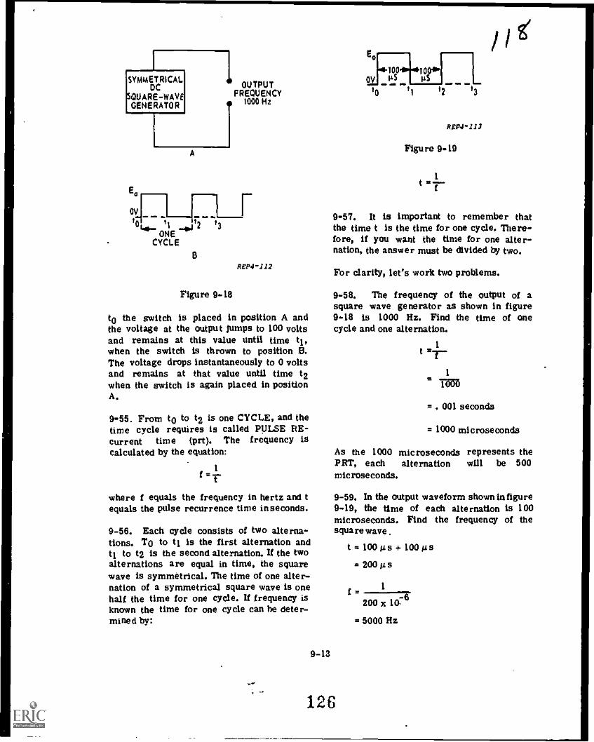
LISYMMETRICAL
DCSQUARE -WAVEGENERATOR
Ea
OVro ti t2 t3ws
ONE11
CYCLE
A
OUTPUTFREQUENCY
1000 Hz
B
Re124 -112
Figure 9 -18
t0 the switch is placed in position A andthe voltage at the output jumps to 100 voltsand remains at this value until time t1,when the switch is thrown to position B.The voltage drops instantaneously to 0 voltsand remains at that value until time t2when the switch is again placed in positionA.
9-55. From t0 to t2 is one CYCLE, and thetime cycle requires is called PULSE RE-current time (prt). The frequency iscalculated by the equation:
1f = r
where i equals the frequency in hertz and tequals the pulse recurrence time inseconds.
9-56. Each cycle consists of two alterna-tions. TO to t1 is the first alternation andt1 to t2 is the second alternation. If the twoalternations are equal in time, the squarewave is symmetrical. The time of one alter-nation of a symmetrical square wave is onehalf the time for one cycle. If frequency isknown the time for one cycle can he deter-mined by:
9-13
E00---94100 100.0,
OV 'is 'is _10
t1 12 13
I,RtP4.1.1.1
Figure 9 -19
1
t =7
0-57. It is important to remember thatthe time t is the time for one cycle. There-fore, if you want the time for one alter-nation, the answer must be divided by two.
For clarity, let's work two problems.
9-58. The frequency of the output of asquare wave generator as shown in figure9-18 is 1000 Hz. Find the time of onecycle and one alternation.
1t .
= . 001 seconds
= 1000 microseconds
As the 1000 microseconds represents thePRT, each alternation will be 500
microseconds.
9-59. In the output waveform shown in figure9-19, the time of each alternation is 100microseconds. Find the frequency of thesquare wave .
126
t= 100ms+ 100 As
= 200 A 5
1
200 x lee= 5000 Hz
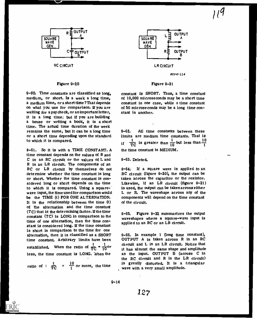
RC CIRCUIT
Figure 9.20
9-60. Time constants are classified as long,medium, or short. Is a week a long time,a medium time, or a short time ?That dependson what you use for comparison. If you arewaiting for a paycheck, or an important lette r,it is a long time; but U you are buildinga house or writing a book, it is a shorttime. The actual time duration of the weekremains the same, but it can be a long timeor a short time depending upon the standardto which it is compared.
9-61. So it is with a TIME CONSTANT. Atime constant depends on the values of R andC in an RC circuit or the values of L andR in an LR circuit. The components of anRC or LR circuit by themselves do notdetermine whether the time constant is longor short. Whether the time constant is con-sidered long or short depends on the timeto which it is compared. Using a square-.wave input, the time used for comparison wouldbe the TIME (t) FOR ONE ALTERNATION.It is the relationship between the time (t)of the alternation and the time constant(TC) that is the determining factor. If the timeconstant (TC) is LONG in comparison to thetime of one alternation, then the time con-stant is considered long. If the time constantis short in comparison to the time for onealternation, then it is classified as a SHORTtime constant. Arbitrary limits have been
t 1established. When the ratio of --A ii or'rt.; 10less, the time constant is LONG. When the
t 10ratio of : iT- = -- or more, the time1
9-14
OUTPUTA
OU TPU TB
SQUAREWAVEGEN
LR CIRCUIT
REP4-1.14
Figure 9-21
constant is SHORT. Thus, a time constantof 10,000 microseconds may be a short timeconstant in one case, while a time constantof 50 microseconds may be a long time con-stant in another.
9-62. All time constants between theselimits are medium time constants. That is
t 1if is greater than but less than 10TC 10
the time Constant is MEDIUM.
9-63. Deleted.
9-64: If a square wave is applied to anRC circuit (figure 9-20), the output can betaken across the capacitor or the resistor.Likewise, if an LR circuit (figure 9-21)
is used, the output can be takenacross eitherL or R. The waveshape across any of thecomponents will depend on the time constantof the circuit.
9-65. Figure 9-22 summarizes the outputwaveshapes where a square-wave input isapplied to an RC or an LR circuit.
9-66. In example 1 (long time constant),OUTPUT A is taken across R in an RCcircuit and L in an LR circuit. Notice thatit has almost the same shape and amplitudeas the input. OUTPUT Et (across C inthe RC circuit and R in the LR circuit)is greatly distorted. It is a triangularwave with a very small amplitude.

OUTPUT "A"Cr IN RC CIRCUIT
EL IN LR CIRCUIT
OUTPUT "13"Ec IN RC CIRCUIT
Er IN LR CIRCUIT
INPUT WAVE
---J 1---J
EX 1LONG TIME CONSTANTT/RC OR Writ. 2 0.1
OR LESS
.................
EX 2 MEDIUM TIME CONSTANT Nv..1 f°,EX 3
SHORT TIME CONSTANTTiRC OR RT/1.2 10
OR MORE
Lure 9-22
9-67. In example 2 (medium time constant),OUTPUT A is distorted with a peak-to-peakamplitude greater than the input. OUTPUT Bis also distorted but less than in example 1.The amplitude has increased and may belessthan or equal to the input.
9-68. In example 3 (short time constant),OUTPUT A is greatly distorted into a peakedwave with a peak-to-peak amplitude of twicethe input amplitude. OUTPUT B, however, hasalmost the same waveshape as the input,with an amplitude equal to the input.
9-69. Thus, we can get a variety of outputwaveshapes with a square wave input bychoosing proper component values for the RCor LR circuit.
9-70. Differentiation and Integration Circuits
9-71. In the introduction to this chapter,it was stated that in electronics the functionof many circuits is to produce nonsinusoidalwaveshapes. Two processes commonlyusedfor waveshaping P 'e differentiation and inte-gration. Your knowledge of transientresponses will help you understand how dif-ferentiation and integration provide a meansfor changing one type ofwaveshape to another
type.
.., .
128
9-15
REP4 -11S
9-72. Differentiating circuits produce anoutput voltage that is proportional to the RATEOF CHANGE of the input, or HOW FAST theinput in changing. A differentiating circuituses a short time constant and the output istaken across the resistor in an RC circuitor the inductor in an LR circuit. See example3, OUTPUT A, of figure 9-22.
9-73. RATE OF CHANGE. Just what ismeant by "rate of change?' Let us plot asteadily increasing voltage against time. Ifthe voltage increases 1 volt per second, theresulting graph would look like line A infigure9-23. If the voltage increases 2 volts per
VOLTS
4
3
2
1
0
....
*"....
.e. '''..-;---------. 'i
Figure 9-23
8
A
C
2 SECONDS
REP4-216

second, the graph would resemble line B. Iton the other hand, the voltage changes only.5 volt/second, the graph would resemble lineC. Which voltage is changing the fastest?Line B, of course, since It went from 0to 4 volts in 2 seconds. Line C would repre-sent the slowest change since It shows achange from 0 to 1 volts in 2 seconds. TheSLOPE of the line then is an indication ofhow fast the voltage is changing. The steeperthe slope, the greater the RATE OF CHANGE.A vertical line would mean maximum rate ofchange. Likewise, a horizontal line wouldmean zero rate of change or no change.
9-74. Deleted.
9-75. Figure 9-25 shows the effect of adifferentiating circuit on asquare wave input.At time t0, the input changes rapidly fromone, steady state to another. The rate ofchange is maximum, and the output voltageis maximum. From to to t1 there is nochange and the output drops to zero volts.How fast it drops to zero depends upon thetime constant of the circuit. At time t1,there is another sudden change of voltage inthe opposite direction, and the output voltageis again maximum, but in the oppositedirection. Look again at figure 9-22 (OUTPUTA in example 3) and note that you can getthe same differentiated wave if you apply asquare wave to a short time constant LRcircuit with the output taken from acrossthe inductor.
9-76. Deleted.
9-77. Integration
9-78. An integrating circuit produces anoutput voltage that is proportional to the areaunder the input waveform. Area equals voltagex time.
9-29. A practical means of producing anintegrated waveshape is to employ a longtime constant RC circuit and take the outputacross the capacitor. The same waveshapecould be developed by using long time constantLR circuit and taking the output across theresistor. See example 1, output B in figure9- 22.
9-16
0U
INPUTR T
P
1uTsp
SHORT TIME CONSTANT CIRCUIT
A
i I
I OUTPUT (Eow)
11 '2 13 14ts
B
Figure 9-25
9-80. Deleted
REP4 -119
9-81. In figure 9-28, at time to, the squarewave input is zero and the charge on Clis zero. As time progresses from to to t1,Cl charges toward the applied voltage pro-ducing an output that increases in amplitude.At time t1 the input passes through zeroand becomes negative. From t1 to t2, Cldischarges to zero and charges toward theapplied negative voltage. At time t2 theinput waveform becomes positive and Cldischarges to zero and charges toward theapplied positive voltage.
9-82. A summary of the results of dif-ferentiation and integration is indicated infigure 9-29. A square wave is shown; how-ever, the circuits that have been describedwill handle any type of waveform.
129
jai

INPUT T OUTPUT
LONG TIME CONSTANT CIRCUIT
411 gimaMINIM.
einOV aim
A
.118. elM 11111 d
9-84. in this chapter, you reviewed thecharacteristics of resistors, capacitors, andInductors; and you learned that a transientvoltage or current is a voltage or currentchanging from one steady state to another.The time required for this change is knownas the transient interval, and the time andamplitude graph of the voltage or current isknown as a waveshape.
I
I_ 9-85. In an RC series circuit you learnedthat the charge and discharge time of thecapacitor is directly proportional to thevalue or resistance and capacitance, and theproduct of the resistance and capacitance is
I called a time constant. A time constant is theI time required for the capacitor to charge toI 63% of the AVAILABLE applied voltage. InI each successive time constant the capacitor
Icharges 63% of the REMAINING voltage. The
It5
t6
=11. 11110M
ti '2 t3
B
Figure 9-28
REP4-122
9-83. Below are listed four brief statementsthat summarize what has been covered on RCand LR circuits.
a. An RC circuit is adifferentiating circuitif the time constant is short and the outputwave is taken from across the resistor.
b. An LR circuit is adifferentiating circuitif the time constant is short and the outputwave is taken across the inductor.
c. An RC circuit is an integrating circuitif the time constant is long and the outputwave is taken across the capacitor.
d. An LR circuit is an integrating circuitif the time constant is long and the outputwave is taken across the resistor.
9-17
0,n
INPUT SQUARE WAVE
INTEGRATED WAVE
DIFFERENTIATED WAVE
Figure 9-29
REp4-123

capacitor is considered fully charged afterFIVE time constants. Conversely, a capacitordischarges 63% of the voltage remaining acrossit during a time constant and is said to becompletely discharged after FIVE time con-stants, The Universal Time Constant Chart isa graph used to determine the percentage ofcharge or discharge of a capacitor plottedagainst the number of time constants. Thevertical axis of the chart indicates thepercentage of full voltage (or current)andthehorizontal axis indicates the number of timeconstants. The number of time constantsis calculated by dividing the time allowed(for the capacitor to charge or discharge)by the time constant (RC).
9-86. The use of the Universal TimeConstant Chart was explained for RC seriescircuits. It was shown that on charge capacitorvoltage is read on the "A" curve and thatresistor voltage and current are read onthe "B" curve, During discharge, all volt-ages and currents are read on the "B"curve.
9-87. The three general categories oftransient problems were discussed:
a. Finding the percent of current and volt-age after a given time.
b. Finding current and voltage after a giventime.
c. Finding component values necessary forthe current and voltage to reach a given valuein a given time. Problems were solved foreach category.
9-88. The values of the inductance andresistance determine the transient responseof an LR circuit. Since the resistance limitsthe final or steady-state value of current inan LR circuit, it is a factor governing therate of current change. The time constantof a series LR circuit is equal to theinductance expressed in henries divided bythe resistance in ohms.
0-80. The use of the Universal TimeConstant Chart with LI1 circuits was ex-plained. It was established that on build-up,inductor voltage is read on the "B" curveand resistor voltage and current are read onthe "A" curve. During decay, all voltagesand currents are read on the "B" curve.Again prOblems were solved to determine LRcircuit transient response.
9-90, You learned the characteristics of aDC symmetrical square wave with emphasis
on the fact that the alternations are of thesame duration. You calculated the time of acycle when the frequency was known and cal-culated the frequency when the time of analternation was known.
9-91. RC time constants were classifiedas long, short, or medium with respect tothe time allowed for the capacitor to chargeor discharge. A time constant is Icing whenit is 10 or more times greater than the timeallowed. A time constant is short when it isonly one-tenth, Or less, as long as the timeallowed. All time constants between 10 timesas long and one-tenth as long, are mediumtime constants. Time constant duration wasemphasized by showing the waveshapes of long,short, and medium time constant circuits.
9-92. Two processes for changing one typeof waveshape to another type we re introduced:(1) differentiation and (2) integration. Dif-ferentiating circuits produce an output inproportion to the rate of change of the input.The circuit uses a short time constant withthe output taken across the resistor in an RCcircuit and across the inductor in an LRcircuit. Integrating circuits produce an outputproportional to the area under the curve.The circuit uses a long time constant withthe output taken across the capacitor in anRC circuit and across the resistor in anLR circuit. We showed how one waveshapemay be changed to another by differentiatingor integrating a square wave.
9-18131

Chapter 10
FILTERS
10-1. We will introduce filters using theseries resonant circuit. But first we needto know what a filter is and why it is used.A filter is a circuit consisting of a numberof impedances grouped together in such away as to have a definite frequency char-acteristic. Filters are designed to pass acertain range of frequencies freely and toblock another range of frequencies.
10-2. Filters make use of the variations ofinductive and capacitive reactance with fre-quency. The variation of impedance in seriesRCL circuits is used to pass or reject cer-tain bands of frequencies. The range overwhich passage occurs freely is called thebandpass; and the range over which poorpassage occurs is called the attenuationband. The frequency at which attenuationstarts to increase rapidly is known as thecutoff frequency.
10-3. Let's review and apply the basicprinciples of the frequency response char-acteristics of the capacitor and inductor.Recall the basic formula for capacitivereactance and inductive reactance.
1
XC 2lrfC
XL = 2j'fL
If we increase frequency, XC decreases andXL increases. U we increase frequencyenough, the capacitor acts as a short andthe inductor acts as an open. Of course theopposite is true; decreasing frequency causesXC to increase and XL to decrease. Hereagain, if we make a large enough change,
the capacitor acts as an open and theinductor like a short. Figure 10-1 gives apictorial representation of these two basiccomponents. Note how they respond to lowand high frequencies.
10-4. U we apply these same principles tosimple circuits (see figure 10-2) they respondas shown for low and high frequencies.
10-5. Let's see how we can use the seriesresonant circuit as a filter. Refer to figure10-3. We know that at resonance EC and ELare equal and opposite (180° out of phase);Z is minimum and current is maximum.If we take an output across the resistorwhen the circuit is at resonance, we get themaximum possible voltage (ER = Ea). As wetune the generator to either side of resonance,the output will decrease. This is shownby thefrequency response curve in figure 10-4.
10-6. The frequency response curve is fora BANDPASS filter (figure 10-4). The fre-quencies between the half power points passto the next circuit. The other frequencieswhich fall below the lower half power point,and the ones above the upper half powerpoint are filtered out; these two bands of
FREQUENCY
LOW HIGH
E)-]T
.
10-1
Figure 10-1
REP4-313

CIRCU.T ACTS AT
LOW HIGH
FREQUENCY
INPUT OUTPUT
1 I
Figure 10- 2
Figure 10-3
10-2
4-
IF
.
1 1---REP4- 314
REPO -315
133

mm. I1
LOW CUTOFF I HIGH CUTOFFLOWER HALF BANDPASS I UPPER HALF
V POWER POINT POWER POINT0
ATTENUATION ATTENUATION BAND
A BAND
L
FREQUENCY
Figure 10-4
frequencies fall in the "attenuation" bands.The half power points are the cutofffrequencies.
10-7. if the output is taken across boththe inductor and capacitor, the frequencyresponse curve resembles figure 10-5. This
REP4116
is a RAND REJECT filter . Band rejectfilters are designed to reject a definiteband of frequencies and pass all otherfrequencies. The LC portion of this circuitappears to the signal as a short at theresonant frequency, and an open for fre-quencies above and below resonance.
Figure 10-5
10-3
134
BANDREJECT
I
BANDPASS BANDPASS
REP4-317
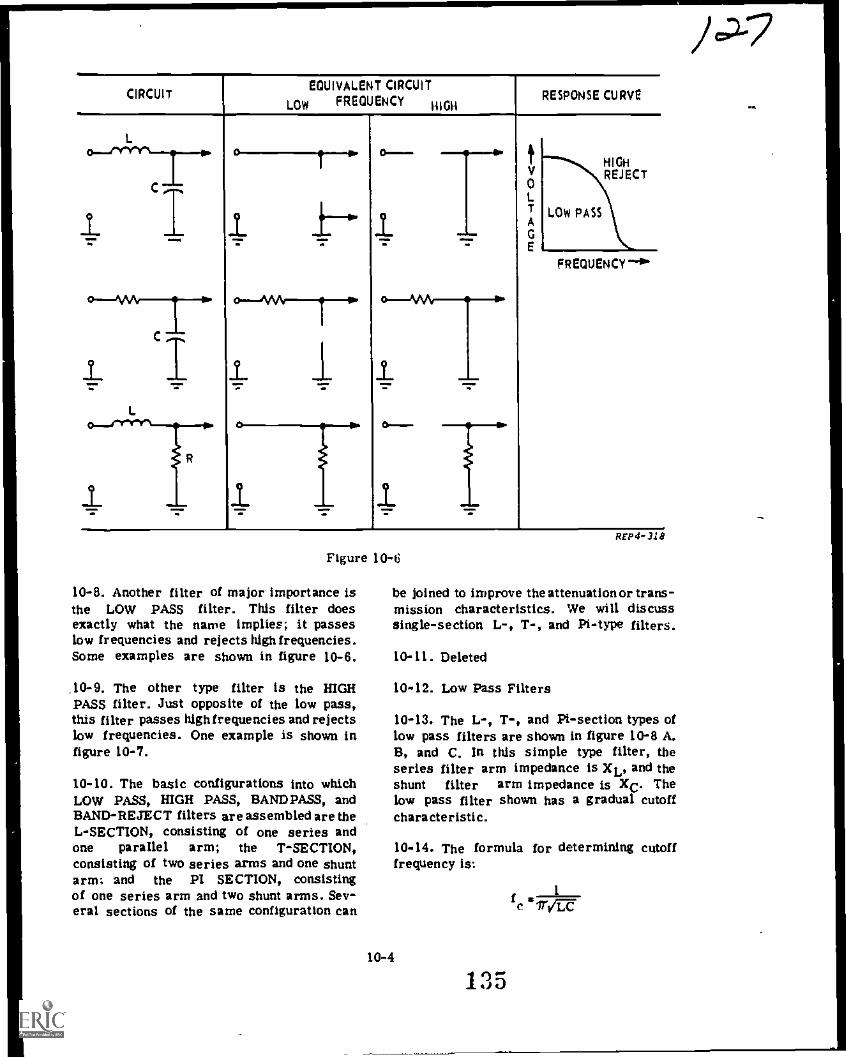
CIRCUITEQUIVALENT CIRCUIT
LOW FREQUENCY HIGHRESPONSE CURVE
L
C
oV0L
A
GE
HIGHREJECT
LOW PASS1
o--app
i. ..._
C
o--MA--TIPP
FREQUENCY
0.--
Figure 10-6
10-8. Another filter of major importance isthe LOW PASS filter. This filter doesexactly what the naive implies; it passeslow frequencies and rejects high frequencies.Some examples are shown in figure 10-6.
.10-9. The other type filter is the HIGHPASS filter. Just opposite of the low pass,this filter passes highfrequencies and rejectslow frequencies. One example is shown infigure 10-7.
10-10. The basic configurations into whichLOW PASS, HIGH PASS, BANDPASS, andBAND-REJECT filters are assembled are theL-SECTION, consisting of one series andone parallel arm; the T-SECTION,consisting of two series arms and one shuntarm; and the PI SECTION, consistingof one series arm and two shunt arms. Sev-eral sections of the same configuration can
REP4- 318
be joined to improve the attenuation or trans-mission characteristics. We will discusssingle-section L-, T-, and Pi-type filters.
10-11. Deleted
10-12. Low Pass Filters
10-13. The L-, T-, and Pi-section types oflow pass filters are shown in figure 10-8 A.B, and C. In this simple type filter, theseries filter arm impedance is XL, and theshunt filter arm impedance is XC. Thelow pass filter shown has a gradual cutoffcharacteristic.
10-14. The formula for determining cutofffrequency is:
10-4
f ae Irt 5.7e
1
MA
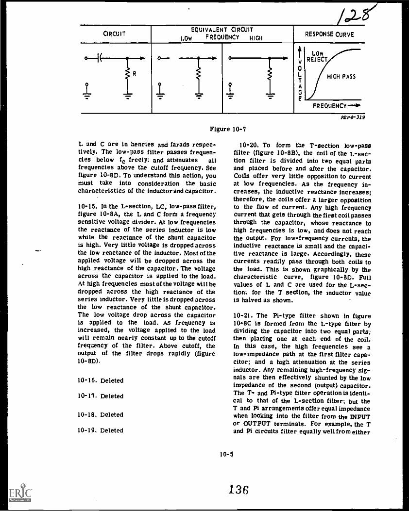
CIRCUITEQUIVALENT CIRCUIT
LOW FREQUENCY HIGHRESPONSE CURVE
1(tV0LTA
GE
LOWREJECT
HIGH PASS
61.. 1
FREQUENCY-10
Figure 10-7
L and C are in henries and farads respec-tively. The low-pass filter passes frequen-cies below fc freely; and attenuates allfrequencies above the cutoff frequency. Seefigure 10-8D. To understand this action, youmust take into consideration the basiccharacteristics of the inductor and capacitor.
10-15. In the L-section, LC, low-pass filter,figure 10-8A, the L and C form a frequencysensitive voltage divider. At low frequenciesthe reactance of the series inductor is lowwhile the reactance of the shunt capacitoris high. Very little voltage is dropped acrossthe low reactance of the inductor. Most of theapplied voltage will be dropped across thehigh reactance of the capacitor. The voltageacross the capacitor is applied to the load.At high frequencies most of the voltage will bedropped across the high reactance of theseries inductor. Very little is dropped acrossthe low reactance of the shunt capacitor.The low voltage drop across the capacitoris applied to the load. As frequency isincreased, the voltage applied to the loadwill remain nearly constant up to the cutofffrequency of the filter. Above cutoff, theoutput of the filter drops rapidly (figure10-8D).
10-16. Deleted
10-17. Deleted
10-18. Deleted
10-19. Deleted
REP4 -310
10-20. To form the T-section low-passfilter (figure 10-8B), the coil of the L-sec-don filter is divided into two equal partsand placed before and after the capacitor.Coils offer very little opposition to currentat low frequencies. As the frequency in-creases, the inductive reactance increases;therefore, the coils offer a larger oppositionto the flow of current. Any high frequencycurrent that gets through the first coil passesthrough the capacitor, whose reactance tohigh frequencies is low, and does not reachthe output. For low-frequency currents, theinductive reactance is small and the capaci-tive reactance is large. Accordingly, thesecurrents readily pass through both coils tothe load. This is shown graphically by thecharacteristic curve, figure 10-8D. Fullvalues of L and C are used for the L-sec-tion; for the T section, the inductor valueis halved as shown.
10-21. The Pi-type filter shown in figure10-8C is formed from the L-type filter bydividing the capacitor into two equal parts;then placing one at each end of the coil.In this case, the high frequencies see alow-impedance path at the first filter capa-citor; and a high attenuation at the seriesinductor. Any remaining high-frequency sig-nals are then effectively shunted by the lowimpedance of the second (output) capacitor.The T- and Pi-type filter operation is identi-cal to that of the L-section filter; but theT and Pi arrangements offer equal impedancewhen looking into the filter from the INPUTor OUTPUT terminals. For example, the Tand Pi circuits filter equally well from either
10-5
136

V.2
Pi m0 f
I I P I
..m411m
(.1 A I - stC t ION 1 -SEC TOON l't -SECTIONFREQUENCYCHARACTER
OWPASS
A1. 1
0....0T11
0 I LI-I LI
IN C2 OUT
1 0
CLI
0
lil0
iitsi 1,iIN
0
IC2 ) C OUtIN C2
0.
OUT
1 _o> 0 lc
'FREQUENCY0.
SIT
E CI F XI 2c I
1----AD
0 c I H
wLt4
0..1>
IIN 2L2 2L2 OUT
0---IIN 42 OUTIN 1.2 OUt
0 °CFREQUENCY
. ,
0AN-pa sS
D
I11 cl
.1 i 1
- LI2 I 2c I 2- L 1
CurrrrL1X
p17114)
K11 CI
L
'1)
11-...1
? II I
1 1C2
IN 42 C2 OUTIN 1.2 c2OUT
IN
21.2
1 C2
OUT
2 o. 2 0 II 12
FREQUENCY
0AN0-11E OE C11014
Li
CI
l7
OUT
7.C2
-4 -0
N 1
- 12.
2C1
Iit 1
2C2
C2 OUT
o
0LI
C1
P
WA
tiAo>
tiI i
2 0IN
1
,..T.iC2
i
2L2
uu 1
1Tic 3
o
IN
o-
0 II 12
r RE QUENCy
oow
137
REP4- 32 3
1

the IN or OUT terminals; you could swapinput and output connections and have nochange in filtering action. This is a sym-metrical filter,
10-22. The L-section filter offers highimpedance to a high frequency at the inputside, but low impedance at the output side.
10-23. High-Pass Filters
10-24. The L-, T-, and Pi- section types ofhigh-pass filters are shown in figure 10-EF, and G. The high-pass filter, like thelow-pass, has a gradual cutoff frequency.
10-25. High-pass filter circuits usinginduc-tance and capacitance have the same con-figurations as do the low-pass filters. Bysimply reversing the position of the com-ponents in the low-pass filter, it becomes ahigh-pass filter. For the L-section LC,high-pass filter, refer to figure 10-8E and H.
10-26. As you will notice the capacitor isnow in series with the input signal; theinductor is in shunt. If the resonant frequencyis applied to this circuit, the capacitoroffers the same amount of opposition as theinductor. When the frequency goes belowresonance, the capacitor will offer moreseries opposition and the inductor offers ashunt path of low opposition to ground. Thisreduces the signal that will reach the load.
10-27. The thing you should notice for theT-section high-pass filter is that the sizesof the capacitors are doubled. See figure10-8F. The value of each capacitor is doubledso that the combination will offer the sameopposition as in the L-section. Notice thevalue of the inductor has not changed. Thesame operational analysis applies to thiscircuit as the L-section.
10-28. For the Pi-section, high-pass filter,the inductors are doubled in value. Seefigure 10-8G. We have, in effect, two induc-tors in parallel; so the effective inductivereactance remains the same as in the othertwo high-pass filters.
10-29. Deleted
10-30. Bandpass Ft !tern 310-31. The L-, T-, and Pi-section types ofbandpass filters are shown in figure 10-81,J, and K. The Frequency characteristicof bandpass filters is shown in figure 1041..Refer to figure 10-81 for basic operation ofthe L-type bandpass filter; LI and Cl forma series-resonant circuit and L2-C2 form aparallel-resonant circuit. The componentsizes are selected so that each circuit willhave the same resonant frequency.
10-32. At the resonant frequency, the seriesresonant circuit (Ll, Cl) offers minimumopposition to the signal. The parallel reso-nant circuit (L2, C2), offers maximum oppo-sition to the signal. This means that maxi-mum signal will pass to the load. If theapplied signal frequency increases ordecreases from resonant frequency, Ll andCl offer a larger opposition and L2 andC2 offer less opposition. The bandpass filterhas an upper and lower cutoff frequency(f1 and f2). These points determine whatfrequencies will pass to the load. Of coursethe values of the circuit components deter-mine where these points will fall.
10-33. Figure 10-9 shows an L-sectionband-pass filter with the componentvalues indicated. This filter will pass fre-quencies between 300 kHz and 500 kHz.Frequencies below 300 kHz and above 500kHz will be attenuated.
Li
CI pr
IN L242.5 nta
10-34. Deleted
400 kA
REP4-122
10-35. The T- and Pi-type bandpass filters,shown in figure 10-8.1 and K, function in thesame manner as the L-type, but are sym-metrical.
10-7
138

10-30. Mind - Reject Filter
10-37. The frequency characteristic of band-rejection filters is shown in figure 10-8P.Refer to figure 10 -3M for the schematicof the L-section band-reject filter.
10-38. Band-reject filters will rejecta certain band of frequencies. Two resonantcircuits are tuned to the center frequencyof the rejected band. The parallel circuit,
LI and Cl, offers maximum opposition tothe resonant frequency. The series circuit,C2 and L2, offers minimum opposition tothis same frequency. Thus, the energy thatis not attenuated by LI-CI is shorted backto the input through L2-C2.
10 -39. The frequency response curve, figure10-8P, shows that the band-reject filter alsohas two cutoff frequencies.
10-8133
!It
I

Chapter 11
COU P1.INO CIRCUITS
11-I. iCoupling' is defined as the meansby which signals are transferred from onecircuit to another. Wires, resistors, coils,capacitors, or transformers may be used toperform this function. Coupling may bedirect, resistive, inductive, or capacitive.
11-2. In this section, we will discuss andanalyze direct-coupling, RC-coupling, LC-coupling, and transformer-coupling circuits.
11-3. Direct Coupling
11-4. The first coupling circuit is directcoupling, as shown in figure 11-1. Directcoupling may use a conductor to connecttwo circuits together; this provides a DIRECTpath for signal currents. This type couplingprovides an exact reproduction of the inputsignal at the output of the coupling circuit.
IDV
PEAK
RI10K'
INPUT
10 Mimi
0--------OUTPUT
20V R210K
DIRECTCOUPLING
A
This exact reproduction is called "highfidelity," which is desirable. It also couplesDC voltages from the input to the output.This has both advantages and disadvantages.
11-5, In place of the wire (figure 11-1A),direct-coupling circuits often use a resistor(figure 11-1B). The coupling resistor isin series with the signal path. The inputvoltages feed through the resistor to theoutput circuit. The loading effect of ZLwill cause a decrease in signal amplitudeat the coupling network output. Currentthrough the coupling resistor causes a volt-age drop which subtracts from the inputsignal.
11-6. Direct coupling operates over a widefrequency range, beginning at 0 hertz.Recallthat frequency does not affect resistance.Direct coupling circuits have no reactivecomponents and are considered "resistive,"with no phase shift.
101/PEAK
R110K
20V R210K
INPUT OUTPUT
DIRECTCOUPLING
B
Figure 11-1
140
iREP4-356

10V
PEAK
15V
C*71"10u
R 1- --I
1
4V1 0
RC 0 -4
COUPLINGC1 i
t
I
iRI t
1
I1
I...1
COUPLINGCIRCUITINPUT
10K
20 VDC
10K c.
Figure 11-2
11-?. RC Coupling
COUPLINGCIRCUITOU TPU T
Raga -357
11-8. Figure 11-2 shows a typical RC cou-pling circuit connecting two circuits. Thesignal applied to ZL is the voltage developedacross the resistor. Observe that the capa-citor blocks the passage of DC voltagefrom one circuit to the other. The input tothe coupling circuit is at a 10-volt reference,but the output reference is zero.
11-9. An important consideration in RC-coupled circuits is the relative magnitude andphase between the input and output voltages.
11-10. As has been discussed in precedinglessons, capacitor current leads capacitorvoltage by 90°. This means that the signalvoltage developed across R3 cannot be inphase with the signal across R2. The voltageacross R3 will lead the voltage across R2by some angle between 0° and 90°. You cansee this if you draw CI and R3 as a seriesCircuit. Use the voltage across R2 as Ea.
11-11. Now, let's consider the effects offrequency on this type of circuit. The higherthe frequency, the smaller the reactance ofthe capacitor, and the more resistive thecircuit. When this happens, resistors R2 and
R3 can be considered to be in parallel. 111,R2, and R3 act like a series-parallel resis-tive circuit. The frequency range whereC acts as a short becomes the operationalfrequency range. This is shown in tho fre-quency response curve of an RC-couplingcircuit, figure 11-3.
11-12. On the other hand, the lower the fre-quency, the greater the reactance of C.This causes a smaller portion of the voltageacross R2 to appear across R3; and a greaterphase difference to exist between ER2 andER3, with ER3 leading. As you recall fromfilter circuits, as the frequency becomeslower, the capacitor acts more like an open.At 0 hertz, the capacitor will completelyblock the signal and the output drops to zeroas shown in figure 11-3.
/33
11-13. The voltage across R3 also drops offat the very high frequencies. If we increasethe frequency above point b In figure 11-3,a factor called "stray Capacitance's atten-uates the signal. Wiring and things like theresistor leads form a capacitance. It issuch a low opposition at high frequenciesthat the signal is greatly attenuated.
11-14. You can see, therefore, that there canbe a large change in output voltage and phasewhen frequency is varied. In practical RC-coupling circuits, the range of frequenciespassed is determined by capacitance.
11-15. At frequencies above point "a" the capa-citor offers a minimum amount of impedance to
ER3
11-2
b
CAUSED BYSTRAY
CAPACITANCEi yr."--
C ACTS AS A SHORTAND R2, R3 ARE IN 1
PARALLELI \i
FREQUENCY go
141
Figure 11-3
REP4.-358
,
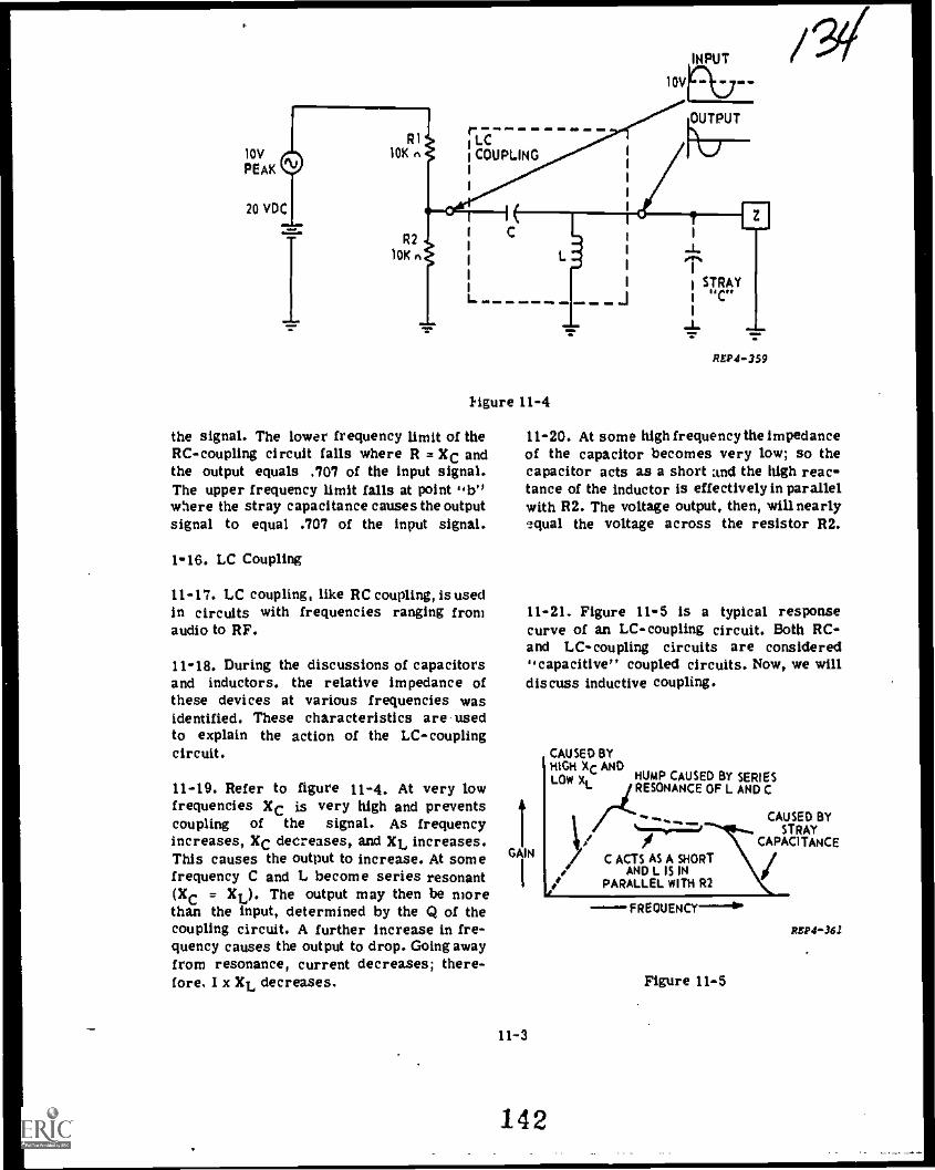
10V
PEAK
20 VDC
R1 Ir
LC'COUPLINGI
I
I
I
I
I
I
10K r.
R210K r.
10V
INPUT%OUTPUT
LMilli 1lMi MI. 111.11111 . Map Y.
Figure 11-4
the signal. The lower frequency limit of theRC-coupling circuit falls where R = XC andthe output equals .707 of the input signal.The upper frequency limit falls at point "b"where the stray capacitance causes the outputsignal to equal .707 of the input signal.
1-16. LC Coupling
11-17. LC coupling, like RC coupling, is usedin circuits with frequencies ranging fromaudio to RF.
11-18. During the discussions of capacitorsand inductors, the relative impedance ofthese devices at various frequencies wasidentified. These characteristics are-usedto explain the action of the LC-couplingcircuit.
11-19. Refer to figure 11-4. At very lowfrequencies XC is very high and preventscoupling of the signal. As frequencyincreases, XC decreases, and XL increases.This causes the output to increase. At somefrequency C and L become series resonant(XC = XL). The output may then be morethan the input, determined by the Q of thecoupling circuit. A further increase in fre-quency causes the output to drop. Going awayfrom resonance, current decreases; there-fore, I x XL decreases.
ASP4-359
/V
11-20. At some high frequencythe impedanceof the capacitor becomes very low; so thecapacitor acts as a short and the high reac-tance of the inductor is effectively in parallelwith R2. The voltage output, then, will nearlyequal the voltage across the resistor R2.
11-21. Figure 11-5 is a typical responsecurve of an LC-coupling circuit. Both RC-and LC-coupling circuits are considered"capacitive" coupled circuits. Now, we willdiscuss inductive coupling.
IGAIN
I
11-3
CAUSED BYHIGH XC ANDLOW XL
142
HUMP CAUSED BY SERIESRESONANCE OF L AND C
%.....:=1/
C ACTS AS A SHORTAND L IS IN
PARALLEL WITH R2
CAUSED BYSTRAY
CAPACITANCE
FREQUENCY ---
Figure 11-5
REP4-362

VOLTAGEAMPLIFICATION
e
10 HZ FREQUENCY
Figure 11-6
11-22. Transformer Coupling
e
10 KHZ
REP4-360
11-23. You studied three types of trans-formers, power, audio, and RF, in pre-ceding lessons. Of these the audio and RFtransofrmers are used in coupling circuits.Coupling transformers consist of two or morecoils that couple energy by mutual inductance.Depending on the frequency, a transformermay use an iron, a magnetic alloy, or anair core. The coil connected to the signal
sourcc is called the primary winding, thecoil connected to the load is called thesecondary winding. The maln area of concernis why transformers are Sometimes used incoupling circuits, rather than RC or LCcoupling.
11-24. Transformer coupling has certaincharacteristics which are not available withother types of coupling circuits. A voltagestep-up or step-down can be obtained witha transformer. The two separate windingsblock DC voltages. Transformer couplingcan be used to couple a hign impedancesource to a low impedance load, or viceversa, by choosing a suitable turns ratio.
11-25. Other characteristics of transformercoupling considered disadvantages are:greater cost, greater shielding requirementsand the possibility of poorer frequency re-sponse at the higher and lower frequencies.Figure 11-6 shows a typical response curveof an audio transformer.
11-4 143
135
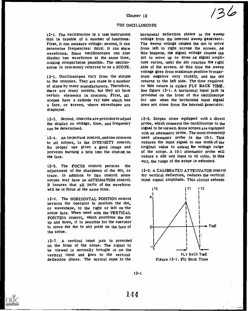
Chapter 12
I'llE OSCILLOSCOPE
12-1. The oscilloscope is a test instrumentthat is capable of a number of functions.First, it can measure voltage; second, it candetermine frequencies; third; it can showwaveforms. Some oscilloscopes can alsodisplay two waveforms at the same time,making comparisons possible. The oscillo-scope is commonly referred to as a SCOPE.
12-1. Oscilloscopes vary from the simpleto the complex. They are made in a numberof sizes by many manufacturers. Therefore,there are many models, but they all havecertain elements in common. First, allscopes have a cathode ray tube which hasa face, or screen, where waveshapes aredisplayed.
12-3. Second, controls are provided to adjustthe display so voltage, time, and frequencycan be determined.
12-4. An important control, and one commonto all scopes, is the INTENSITY control.Its proper use gives a good image andprevents burning a hole into the coating onthe face.
12-5. The FOCUS control permits theadjustment of the sharpness of the dot, ortrace. In addition to this control somescopes may have an ASTIGMATISM control.It insures that all parts of the waveformwill be in focus at the same time.
12-6. The HORIZONTAL POSITION controlpermits the operator to position the dot,or waveshape, to the right or left on thescope face. When used with the VERTICALPOSITION control, which positions the dotup and down, it is possible for the operatorto move the dot to any point on the face ofthe scope.
12-7. A vertical input jack is providedon the front of the scope. The signal tobe viewed is normally brought in on thevertical input and goes to the verticaldeflection plates. The normal input to the
,......MIONmll.IIMI
/36horizontal deflection plates is the sweepvoltage from the internal sweep generator.The sweep voltage causes the dot to movefrom left to right across the screen. Asthis happens, the signal voltage causes thedot to move up or down as signal ampli-tude varies, until the dot reaches the rightside of the screen. At this time the sweepvoltage goes from maximum positive to maxi-mum negative very rapidly, and the dotreturns to the left side. The time requiredor this return is called FLY BACK TIME.See figure 12-1. A horizontal input jack isprovided on the front of the oscilloscopefor use when the horizontal input signaldoes not come from the internal generator.
12-8. Scopes come equipped with a directprobe, which connects the oscilloscope to thesignal to be viewed. Some scopes are equippedwith an attenuator probe. The most commonlyused attenuator probe is the 1011. Thisreduces the input signal to one tenth of theoriginal value to extend the voltage rangeof the scope. A 10:1 attenuator probe willreduce a 400 volt input to 40 volts. In thisway, the range of the scope is extended.
12-1
144
12-9. A CALIBRATED ATTENUATOR controlfor vertical deflection, reduces the verticalinput signal amplitude. This circuit extends
1 TO
+I
I T1
I
111
iI I
1
1
I
I
1
I 1
I.
1
I
TIME
..)--FLY BACK TIME
Figure 12-1. Fly Back Time

/37the range of the scope. Using it, a largeinput voltage can be reduced and measured.Without it the signal would extend off thescope. Damage to the scope could possiblyresult. Any voltage applied to the verticalplates will cause the dot to extend up anddown in proportion to the voltage applied.
12-10. In addition to vertical deflection, inorder to analyze 1.vaveshapes, we must havethe dot extended into a line across theface of the scope horizontally. For this, thescope has a SWEEP circuit which causes thespot to sweep across the screen. Actually,the dot is first positioned to the left side ofthe screen, and then, by electrostatic orelectromagnetic fields, the dot is moved fromleft to right. As soon as it reaches the rightside, it is quickly moved back to the leftto retrace the path just made. When the dotsweeps across the screen, it will appear asa solid line to the eye. The inner surfaceof the CRT screen is coated with a phos-phorescent material which glows for a timeafter the dot has moved; this is calledPERSISTENCE of the screen. The rate ofmovement can be controlled by horizontalsweep circuits inside the scope. It is the
i 3 4
VERTICAPThil.DEFLECTION
INPUT\...)1
CATHODE-RAY
TUBE
Figure 12-2. Deflection Inputs
horizontal sweep that must be synchronizedwith the input waveform to cause the inputwaveform to appear stationary on the face ofthe scope. Obviously, the horizontal sweepvoltage is applied to the horizontal deflec-tion plates (figure 12-2), and the input wave-form is applied to the vertical deflectionplates.
12-11. The oscilloscope you will be usingin the Electronic Principles Course is theBallantine pictured in figure 12-3. The con-trols are numbered on figure 12-3 and thesenumbers match the first column call -out
S 6 7
Figure 12-3
12- 2
145
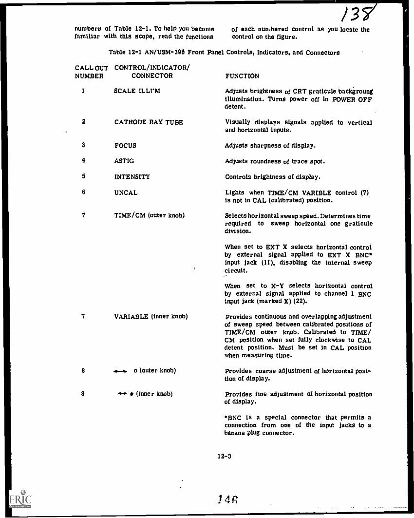
/3numbers of Table 12-1. To help you become of each numbered control as you locate thefamiliar with this scope, read the functions Control on the figure.
Table 12-1 AN/USM-398 Front Panel Controls, Indicators, and Connectors
CALL OUT CONTROL/INDICATOR/NUMBER CONNECTOR FUNCTION
1 SCALE ILLI'M Adjusts brightness of CRT graticule backgroungillumination. Turns power off in POWER OFFdetent.
2 CATHODE RAY TUBE Visually displays signals applied to verticaland horizontal inputs.
3 FOCUS Adjusts sharpness of display.
4 ASTIG Adjusts roundness of trace spot.
5 INTENSITY Controls brightness of display.
6 UNCAL Lights when TIME/CM VARIBLE Control (7)is not in CAL (calibrated) position.
7 TIME /CM (outer knob) Selects horizontal sweep speed. Determines timerequired to sweep horizontal one graticuledivision.
When set to EXT X selects horizontal controlby external signal applied to EXT X BNC*input jack (11), disabling the internal sweepcircuit.
When set to 3fif selects horizontal controlby external signal applied to channel 1 BNCinput jack (marked X) (22).
7 VARIABLE (inner knob) Provides continuous and overlapping adjustmentof sweep speed between calibrated positions ofTIME/CM outer knob. Calibrated to TIME/CM position when set fully clockwise to CALdetent position. Must be set in CAL positionwhen measuring time.
8
B
..s--.1.. o (outer knob) Provides coarse adjustment of horizontal posi-tion of display.
4* (inner knob) Provides fine adjustment of horizontal positionof display.
BNC is a special connector that permits aconnection from one of the input jacks to abanana plug connector.
12-3
141

/s9Table 12-1. AN/USM-309 Front' Panel Controls, Indicators, and Connectors (Cont)
CALL OUT CONTROL/INDICATORNUMBER CONNECTOR
8 PULL X10 MAO (Inner knob)
9 CAL IV
10 BEAM FINDER
11 EXT X
12. TRIG SELECT (outer knob)
FUNCTION
In pulled-out position, causes magnification ofhorizontal sweep or EXT X signal byfactor of 10
Test point provides I-kHz square wave at 1 voltp-p amplitude. May be used for vertical sensi-tivity calibration and divider probe compensation.
Reduces gain of deflection circuits, thus limitingbeam deflection to within the CRT graticule.Also operates on blanking amplifier to releasesweep retrace blanking,
NOTE
Make sure INTENSITY control (5) is turnedup high enough to make beam visible whenusing BEAM FINDER, but not too brightso as to burn the coating.
Connector for an external horizontal input.
Selects source of timebase trigger signal asfollows:
LINE - Pickoff from ac linevoltage, positive or nega-tive slope.
CH1 - Pickoff from CH1 ver-tical amplifier signal,positive or negativeslope.
CH1 * 2 - Pickoff from the dis-played composite verti-cal deflection signal,positive or negativeslope. (Not to be usedin CHOP mode.) Use withACF and DC triggercoupling.
EXT - Pickoff from externaltrigger applied to EXTTRIO jack (13), posi-tive or negative slope.
- Sweep recurs at maxi-mum repetition rateandwith speed set by theTIME / CM switch.
FREE RUN
12-4
.1.7

10Table 12-1. AN/USM-308 Front Panel Controls, Indicators, and Connectors (Cont)
CALL OUT CONTROL/INDICATOR/NUMBER CONNECTOR
12 LEVEL (inner knob)
13 EXT TRIG
14 CHOP-ALT switch
15 AC- ACF-DC (Trigger Coupling)
16 PULL TO INVER T CH2
17 SEPARATE - CHI & CH2
18 Y (CH2 input)
FUNCTION
Selects point on amplitude of trigger signalthat starts sweep. In AUTO position, sweepsynchronizing triggers are produced automati,callywhen signal exceeds 40-Hz repetition rateand exceeds minimum level. In absence oftrigger signals, sweep runs free to producebright line.
Connector for external trigger signal.
Selects display switching mode for dual tracevertical deflection,
ALT
CHOP
- CHI and CH2 alternatewith each sweep. Usedfor normal dual tracedisplays
- CHI and CH2 alter-nate at 400 kHz. Usedonly when com paring sig-nals on long time bases(slower than 1ms/cm).Never used with CHI &2 trigger selection.Never used with time-base sweeps faster than1 ms/cm.
Selects capacitive or direct coupling of triggersignal. Direct coupling (DC) is normally usedfor slow or erratic sync signals. Capacitivecoupling (AC) blocks DC componentbut attenuatessignals below 50 Hz. Fast capacitive coupling(ACF) attenuates signals below 50 kHz and isused to block unwanted low frequency com-ponents of the trigger signals.
Selects polarity for CH2 display. In pulled outposition inverts CH2 polarity.
Selects mode for display of vertical deflectionchannels, separate or added.
Connector for CH2 vertical input signal-
19 UNCAL Lights when either VOLTS/CM VARIABLE con-trol (20) is not in CAL position.
12-5
148

Table 12-1. AN/USM013 Front Panel
CALL OUT CONTROL/INDICATOR/NUMBER CONNECTOR
20 CH1 VOLTS/CM(outer knob)
20 CH1 VARIABLE(inner knob)
21 CHI ACMID-DC(input Coupling)
22 X (CHI input)
23
24
25
26
27
CHI t
BAL
CH2 OUT
Y CAL
Power
Controls, Indicators, and Connectors (Cont)
FUNCTION
Selects channel 1 vertical deflection factor forcalibrated measurements.
Provides continuous uncalibrated adjustmentsbetween calibrated positins of outer knob. Mustbe set to CAL position when measuring voltage.
Set to AC when applying an AC signal or DCwhen applying a DC signal. GND grounds outeither signal to enable operator to establish areference line.
Connector for CHI vertical input signal and forhorizontal input signal when TIME/CM switch(7) is set to X-Y position.
Adjusts vertical position of CHI display. SwitchesCHI off when in OFF detent.
Adjusts to minimize vertical position changewhen rotating volts/cm switch.
Connector for output of CH2 vertical amplifiersignal.
Provides adjustment of vertical sensitivity forboth channels.
Lights when operating line power is applied.
Probe trimmer screw Adjusts frequency compensation of attentatoradjustment (not shown) probe.
12-12. To effectively use the oscilloscope,it is necessary to have a more completeunderstanding of the function of certaincontrols and accessories.
12-13. TIME/CM Control
12-14. The time it will take the electron totravel across the scope is determined bythe TIME/CM control. The control is dividedinto three areas of time from 1 second to.5 microseconds.
12-6
12-15. The CRT scale is divided into 10horizontal divisions that are 1 centimeterapart. if the TIME/CM control were set tothe 1 microsecond position, the sweep wouldmove I centimeter in I microsecond, orcompletely across the scale in 10 micro-seconds. If an AC signal on the scale showsthat 1 cycle is 7 centimeters long and theTIME/CM control is set to 5 microseconds,the time for one cycle would then be 35microseconds. A horizontal scale permitssignals to be measured in tenths of a
149
10
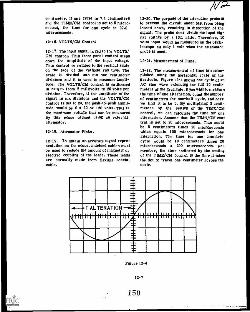
centimeter. If one cycle is 7.4 centimetersand the TIME /CM control is set to 6 micro-second, the time for one cycle is 37.0microseconds.
12-16. VOLTS/CM Control
12-17. The input signal is fed to the VOLTS/CM control. This front panel control stepsdown the amplitude of the input voltage.This control is related to the vertical scaleon the face of the cathode ray tube. Thescale is divided into six one centimeterdivisions and it is used to measure ampli-tude. The VOLTS/CM control is calibratedin ranges from 5 millivolts to 20 volts perdivision. Therefore, if the amplitude of thesignal is six divisions and the VOLTS/CMcontrol is set to 20, the peak-to-peak ampli-tude would be 6 x 20 or 120 volts. This isthe maximum voltage that can be measuredby this scope without using an externalattenuator.
12-18. Attenuator Probe.
12-19. To obtain an accurate signal repre-sentation on the scope, shielded cables mustbe used to reduce the amount of magnetic orelectric coupling of the leads. These leadsare normally made from flexible coaxialcable.
12-20. The purpose of the attenuator probe isto prevent the circuit under test from beingloaded down, resulting in distortion of thesignal. The probe does divide the input sipnal voltage by a 10:1 ratio. Therefore, 10volts input would be measured on the oscil-loscope as only 1 volt when the attenuatorprobe is used.
12-21. Measurement of Time.
12-22. The measurement of time is accom-plished using the horizontal scale of thegraticule. Figure 12-4 shows one cycle of anAC sine wave extending the full 10 centi-meters of the graticule. If you wish to measurethe time of one alternation, count the numberof centimeters for one-half cycle, and herewe find it to be 5, By multiplying 5 centi-meters by the setting of the TIME/CMcontrol, we can calculate the time for onealternation. Assume that the TIME /CM con-trol is set to 20 microseconds. This wouldbe 5 centimeters times 20 microsecondswhich equals 100 microseconds for onealternation. The time for one completecycle would be 10 centimeters times 20microseconds = 200 microseconds. Re-member, the time indicated by the settingof the TIME /CM control is the time it takesthe dot to travel one centimeter across thescale.
I.
1 ALTERATION
WI 1111 IIII III
A
M11.,..1111 1111 1111 III
Figure 12-4
12-7
150

12-23. Calculating Frequency.
12-24. Now that you can measure sweeptlme,it is very easy to calculate the frequency ofthe AC signal. The formula used is:
Frequency s Ttme
12-25. When determiningfrequency, you mustalways determine the time for one cycle.In the preceding example, the time for onecycle is 200 microseconds. Inserting thisinto the formula, we find:
f200 x 10-6
1
f = 5 kHz
12-26. When setting up the oscilloscope tomeasure an unknown frequency, you shouldobtain as near one cycle across the scaleas possible by using the TIME/CM control.You must also insure that the VARIABLETIME/CM control is In the CAL positionor your reading will not be accurate. Figure12-5 shows an AC Signal on the scope thatis 6.8 centimeters for one complete cycle.If the TIME /CM control is set to 5 micro-seconds, the time for one cycle would be:
6.8 centimeters x 5 microseconds = 34microseconds
4-ONE CYCLE
VAIDEMEMENIM,WHIMINIM111111111111111111
11111111111111111VAIMINIIMENNEWM11
Figure 12 -5
4
0
1101111M110111111121pi U1Vii71
NNUUV4U
MEMtiii1111.1151_11.
11111.111111Wil11111111M
II WIIM1115
moo .IFigure 12-6
12-27. Applying the time for one cycle tothe formula:
1. 1f --=6-= 29,411 Hz34 x 10
12-28. Measurement of Phase
12-29. The dual-trace capabilay of the oscil-loscope is very useful for measuring phasedifference of two sine waves having thesame frequency. Figure 12-6 shows the twosine waves being displayed on the oscil-loscope. One waveform is positioned directlyover the other (superimposed) so the dif-ference in phase is easy -o see. This isshown as distance X and equals 3 centi-meters. X also represents the unknown phaseangle. One complete sine wave is distanceY and equals 8 centimeters.
Distance Y also represents 360 degrees(one complete sine wave).
Dividing 360 degrees by 8 centimetersresults in each centimeter equalling 45degrees.
360 degrees = 45 degrees per centimeter
Multiplying the 3 centimeters difference inthe waves by the 45 degrees per centimeterresults in a phase difference of 135 degrees.
12-8
3 cm x 45 degrees/cm = 135 degrees
151

11,411k, IRA111111111
iniamprinNiumrimssilimuimmwENE mum
3500
Figure 12-7
12-30. Lets try another example. See figure12-7. Here the phase is different but, theprocedure is the same. There are twocentimeters difference between the two waves.Two centimeters x 45 degrees/cm = 90degrees. This gives the phase differencebetween the two signals. Notice the distanceswere all measured from like points on thesine waves. Y is measured between thepoints where sine wave A corsses the zeroreference line and starts positive. X ismeasured between the zero crossing of sinewave B and sine wave A, where they startgoing positive. Also notice that wave Acrosses zero after wave B has crossed zero.Sine wave A lags sine wave B by 90 degrees.
12-31. Amplitude Measurement.
12-32. In measuring voltages with the scope,it must be kept in mind that it measures thePEAK-TO-PEAK value. If the signal is asine wave, the peak-to-paek value may beconverted to the RMS or EFFECTIVE valueby multiplying the peak-to-peak value by.3535.
EXAMPLE; If the peak-to-peak value is200 volts, the effective value is 200 x .3535or 70.7 volts.
12-33. The graticule scale on the face of theCRT is used for measuring voltage ampli-tude. When an AC signal is observed on thescope, a quick calculation can be made todetermine its peak-to-peak voltage amplitude.
111111011111=1111
111111111111MEMMINNOM111111111511.1111111101111111
mmimiimmisFigure 12-8
Refer to figure 12-8. This shows an ACsignal 3.8 centimeters in amplitude peak-to-peak. When checking the VAR/ABLEVOLTS/CM control, we find it is in theCAL position and the VOLTS/CM control isset on 10. You can calculate 3.8 centimetersx 10 volts/cm a 38 volts peak-to-peak. Whenreading sinusoidal voltages, we normally usea meter which shows effective voltage. Inorder to convert from peak-to-peak toeffective voltage, use the following formula.
Peak-to-peak x .3535 = Effective
12-34. Therefore, if you were reading 38volts peak-to-peak, insert it into the formulaas follows:
38 x .3535 = 13.433 Effective Volts
12-35. You should keep in mind that thehighest range of the VOLTS/CM control is20, and there are only six divisions ver-tically on the scale. Therefore, the peak-to-peak voltage that you can measure in theCAL position is 120 volts.
12-36. Measurement of DC Voltage
12-37. To measure a DC voltage groundthe input probe to the oscilloscope andmove the trace down to the bottom line ofthe scale by using the Vertical Positioningcontrol. Figure 12-9 shows the measurementof DC voltage. After establishing a groundreference, the probe is placed on the DCvoltage to be measured. The trace movedup to point B or 4.4 centimeters. If the
12-9
152

me memINN MANNINMUM MMEIM
Figure 12-9
VOLTS/CM control was set to 10, the DCvoltage shown on the scale would be 44volts. If the trace had moved down, itwould indicate the presence of a negativeDC voltage and the ground reference wouldhave to be set at the top of the scale.Agatn, the maximum voltage that can bemeasured directly is 20 volts per division,or 120 volts. Higher voltages can be measuredif an external attenuator is used at theinput jack.
12-10
153
U S 60,1111114110 flUall14 Off1(1 1976-671- 5htd 16)
At( 16/

Technical Training
ATC-GP3A0R3X020-1Prepared by Kees ler TTC
KEPGP-20
ELECTRONIC PRINCIPLES (MODULAR SELF-PACED)
MODULE 20
OSCILLOSCOPE USES
ATC Kees ler 6-2726
JANUARY 1976
AIR TRAINING COMMAND
7.-7
Designed For ATC Course Use
00 HOT VSE ON THE JOB
154

Radar Principles BranchKees ler Air Force Base, Mississippi
ATC GP 3AQR3X020-IKE P-GP- 20
January 1978
ELECTRONIC PRINCIPLES (MODULAR SELF-PACED)
MODULE 20
OSCILLOSCOPE USES
This Guidance Package is designed to guide you through this module of the ElectronicPrinciples Course. It contains specific information, including references to other resourcesyou may study, enabling you to satisfy the learning objectives.
CONTENTS
Title
OverviewList of ResourceAdjunct GuideLaboratory Exercises:
20-120-220-320-4
Module Self-CheckAnswers
OVERVIEW
1. SCOPE: The oscilloscope is a testinstrument that can be used to measurevoltage or time and show waveforms. Oscil-loscopes vary from simple to complex. Somecan display two or more waveforms at thesame time. This module provides an intro-duction, detailed operating procedures, andpractical training for a dual-trace general-purpose oscilloscope.
2. OBJECTIVES: Upon completion of thismodule, you should be able to satisfy thefollowing objectives:
a. Given an oscilloscope, trainer, andformulas, measure the time and calculate thefrequency of an AC voltage within +10percent accuracy.
Supersedes KEP-GP-20, 1 July 1974.
Page
I,
i1
29
1011
1316
b. Given a dual trace oscilloscope andtrainer, determine within +10 percentaccuracy the phase relationship by comparingtwo signals of the same frequency.
c. Given an oscilloscope and trainer,measure the amplitude of DC and AC volt-ages +10 percent accuracy.
LIST OF RESOURCES
To satisfy the objectives of this module,you may choose, according to your training,experience, and preferences, any or all ofthe following:
READING MATERIALS:
DigestAdjunct Guide with Student Text
r-,..);.)i
Om.

AUDIO0VISUAL9:
Television Lesson, Use of Oscilloscope,TVK 30-212A
Television Lesson, Frequency and PhaseMeas., TVK 30-2128
(NOTE: These lessons refer to adifferent oscilloscope, but the controlsare basically the same as on the scopeyou will use.)
LABORATORY EXERCISES:
Introduction to the Oscilloscope 20-1
Frequency Measurements 20-2
Phase Measurements 20-3
Voltage Measurements 20-4
AT THIS POINT, IF YOU FEEL THATTHROUGH PREVIOUS EXPERIENCE ORTRAINING YOU ARE FAMILIAR WITHTHIS SUBJECT, YOU MAY TAKE THEMODULE SELF-CHECK. IF NOT, SELECTONE OF THE RESOURCES AND BEGINSTUDY.
CONSULT YOUR INSTRUCTOR IF YOUNEED HELP.
ADJUNCT GUIDE
INSTRUCTIONS:
Study the referenced materials as directed.
Return to this guide and answer thequestions.
Confirm your answers in the back of thisguidance package.
If you experience any difficulty, contactyour. instructor.
Begin the program.
A. Turn to Student Text, Volume in, andread paragraphs 12-1 through 12 -20. Returnto this page and answer the following questions.
1
/ 7 6I. Which ie NOT a common uae of the scope?
a. Measure voltage.
b. Measure current.
-_---- c. Measure frequency.
d. Display waveforms.
2. Intensity of the trace should be:
a. High at all times so that thewaveshape can easily be seen.
b. No higher than is necessaryto clearly see the waveshape.
c. At whatever brightness theoperator chooses.
d. Adjusted by centering the inten-sity control at all times, regardless ofbrightness.
3. One element that all scopes have incommon is:
a. The cathode ray tube.
b. Electromagnetic deflection.
c. An attenuator probe.
d. Capability of displaying two wave-forms simultaneously.
CONFIRM YOUR ANSWERS
B. Turn to Laboratory Exercise 20-I. Thisexercise will familiarize you with the con-trols of the scope and provide you withpractice in the use of these controls. Returnand continue with this program upon comple-tion of the exercise.
C. Turn to Student Text, Volume III, and readparagraphs 12 -21 through I2 -30. Return tothis page and answer the following questions.
1. Find the frequency of a signal if onecycle is 2.5 cm long on the scope and theTIME/CM control is set on 2 mS..
156

2. It a signal of 1000 Hz is displayed on YOU MAY STUDY ANOTHER RESOURCEthe scope and TIME/CM control is set on:
a. .1 mS
b. .2 mS
c. .5 mS
What will be the length of one cycle in cm?
a.
b.
c.
3. If the phase difference between two signalsis 0.5 cm and the length of one cycle is8 cm, then the phase difference is:
degrees.
CONFIRM YOUR ANSWERS
D. Turn to Laboratory Exercise 20-2 and20-3 in which you will actually use the scopeto make frequency and phase measurements.Return and continue with this program uponcompletion of the exercise.
E. Turn to Student Text, Volume III, andread paragraphs 12-31 through 12-37. Returnto this page and answer the following questions.
1. What is the peak-to-peak amplitude of asignal that is 3.5 cm in height on the scopewith the VOLTS/CM control set on 2V?
2. What is the effective voltage of a signalit it is 4 cm high on the scope and the VOLTS/CM control is set on 5V?
3. How many cm in height will a 10 VACsignal be if the VOLTS/CM control is seton 10V?
CONFIRM YOUR ANSWERS
F. Turn to Laboratory Exercise 20-4. Inthis exercise you will practice using thescope to measure voltage.
2
OR TAKE THE MODULE SELF-CHECK.
LABORATORY EXERCISE 20-1
Introduction to the Oscilloscope
OBJECTIVES:
1. Match each control with its functionwhen gven a list of oscilloscope controls anda list of their functions.
2. When given a diagram of the frontpanel of the oscilloscope, locate and labelthe controls while observing an actual scopeand a list of its controls.
3. Locate and demonstrate the use of theoscilloscope controls needed to properlydisplay one cycle of a sine wave, centeredon the scope with a vertical size of 4 centi-meters and a horizontal size of 10 centimeters.
EQUIPMENT;
Oscilloscope, AN/USM-398Sine-Square Wave Generator 4864
REFERENCES:
Student Text Volume III, paragraphs 12-1through 12-20.
CAUTION: OBSERVE BOTH PER-SONNEL AND EQUIPMENT SAFETYRULES AT ALL TIMES. REMOVEWATCHES AND RINGS.
PROCEDURES:
A. Read the list of objectives given forthis exercise. Keep in mind that the exer-cise is designed to guide' you through cer-tain steps so that you will be able to doeach of the objectives. The objectives willbe accomplished one at a time.
1. Read table I-I and locate each controlon the oscilloscope.
157
I Vq
...

Table IA. AN/USM.300 Front Panel Controls, Indicators and Connectors
CALL OUT CONTROL/INDICATOR/NUMBER CONNECTOR
1 SCALE ILLUM
2
3
4
5
6
7
8
8
8
CATHODE RAY TUBE
FOCUS
ASTIG
INTENSITY
UN CAL
TIME / CM (outer knob)
VARIABLE (inner knob)
4.--", (outer knob)
d-' (inner knob)
PULL X10 MAG (innerknob)
FUNCTION
i 5°
Adjusts brightness of CRT graticule backgroundillumination. Turns power off in POWER OFFdetent.
Visually displays signals applied to verticaland horizontal amplifiers.
Adjusts sharpness of display.
Adjusts roundness of trace spot.
Controls brightness of display.
Lights when TIME/CM VARIABLE control (7)is not in CAL position.
Selects horizontal sweep speed. Determines timerequired to sweep horizontal one graticuledivision. By pulling PULL X10 MAG knob (8),display Can be expanded by le, increasingfastest sweep to 50 ns /cm.
When set to EXT X selects horizontal Controlby external signal applied to EXT X BNC inputjack (11).
When set to X-Y selects horizontal control byexternal signal applied to channel 1 BNC inputjack (marked x) (22).
Provides continuous and overlapping adjustmentof sweep speed between calibrated positions ofTIME/CM outer knob. Calibrated to TIME/CMposition when set fully clockwise to CAL detentposition. Turned counterclockwise, sweep speeddecreases; however, TIME/CM readings areuncalibrated .
Provides coarse adjustment of horizontal posi-tion of display.
Provides fine adjustment of horizontal Positionof display.
In pulled-out position, causes magnification ofhorizontal sweep or EXT X signal by factor of10.
3
158
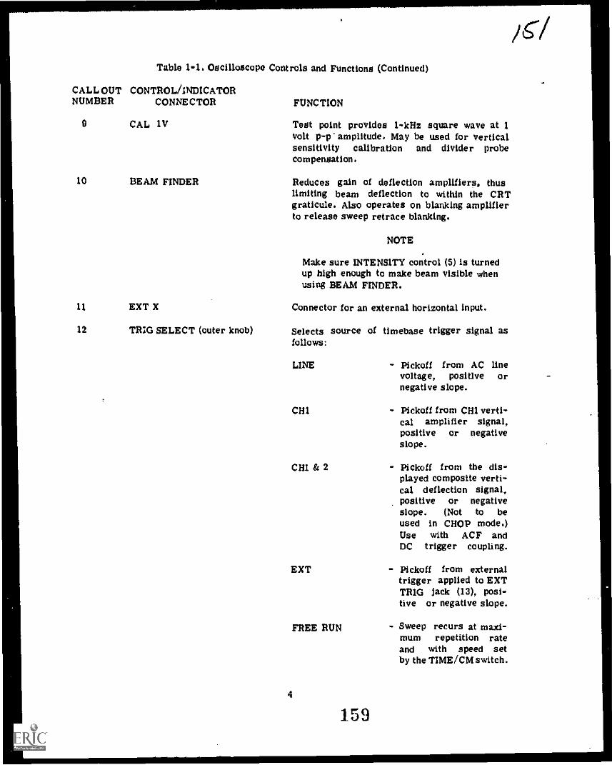
Table 1-1. Oscilloscope Controls and Functions (Continued)
CALL OUT CONTROL /INDICATORNUMBER CONNECTOR
0 CAL 1V
10 BEAM FINDER
11 EXT X
12 TRIG SELECT (outer knob)
FUNCTION
Test point provides 1-kHz square wave at 1volt p-p amplitude. May be used for verticalsensitivity calibration and divider probeCompensation.
Reduces gain of deflection amplifiers, thuslimiting beam deflection to within the CRTgraticule. Also operates on blanking amplifierto release sweep retrace blanking.
NOTE
Make sure INTENSITY control (5) is turnedup high enough to make beam visible whenusing BEAM FINDER.
Connector for an external horizontal input.
Selects source of timebase trigger signal asfollows:
LINE
CH1
CH1 & 2
EXT
FREE RUN
4
159
- Pickoff from AC linevoltage, positive ornegative slope.
- Pickoff from CH1 verti-cal amplifier signal,positive or negativeslope.
- PiCkoff from the dis-played composite verti-cal deflection signal,positive or negativeslope. (Not to beused in CHOP mode.)Use with ACF andDC trigger coupling.
- Pickoff from externaltrigger applied to EXTTRIG Jack (13), posi-tive or negative slope.
- Sweep recurs at maxi-mum repetition rateand with speed setby the TIME /CM switch.
/61

Table 1-1. AN/USM-398 Front Panel Controls, Indicators, and Connectors (Continuea)
CALL OUT CONTROL/INDICATOR/NUMBER CONNECTOR
12 LEVEL (inner knob)
13 EXT TRIG
14 CHOP-ALT switch
15 AC-ACF-DC (TriggerCoupling)
16 PULL TO INVERT CH2
17 SEPARATE - CHI & CH2
18 Y (CH2 input)
FUNCTION
Selects point on amplitude of trigger signalthat starts sweep. In AUTO position, sweepsynchronizing triggers are produced automati-cally when signal exceeds 40-Hz repetitionrate and exceeds minimum level. In absenceof trigger signals, sweep runs free to producebright line.
Connector for external trigger signal.
Selects display switching mode for dual tracevertical dfIection.
ALT
CHOP
- CHI and CH2 alter-nate with each sweep.Used for normal dualtrace displays.
- CHI and CH2 alter-nate at 400 kHz.Used only when com-paring signals on longtime bases (slowerthan 1 ms/cm). Neverused with CHI &2 trigger selection.Never used with time-base sweeps fatterthan 1 ms/cm.
Selects capacitive or direct coupling of triggersignal. Direct coupling (DC) is normally usedfor slow or erratic sync signals. Capacitivecoupling (AC) blocks DC component but atten-uates signals below 50 Hz. Fast capacitivecoupling (ACF) attenuates signals below 50kHz and is used to block unwanted low fre-quency components of the trigger signals.
Selects polarity for CH2 display. In pulled outposition inverts CH2 polarity.
Selects mode for display of vertical deflectionchannels, separate or added.
Connector for CH2 vertical input signal.
3
160
/5 '

Table 1 -1. AN /USM -398 Front Panel Controls, Indicators, and Connectors (cont)
CALL OUT CONTROL /INDICATOR/NUMBER CONNECTOR
19 UNCAL
20 CHI VOLTS/CM(outer knob)
20 CHI VARIABLE (inner knob)
21 CHI AC-GND-DC(Input Coupling)
22 X (CHI input)
23
24
25
26
27
CHI
HAL
CH2 OUT
Y CAL
Power
Probe trimmer screwadjustment (not shown)
FUNCTION
Lights when either VOLTS/CM VARIABLEcontrol (20) is not in CAL position.
Selects channel 1 vertical deflection factor forcalibrated measurements.
Provides continuous uncalibrated adjustmentsbetween calibrated positions of outer knob.Calibrated to VOLTS/CM positions when setfully clockwise to CAL detent position.
Selects capacitive (AC) or direct (DC) couplingof input signal; or grounds (GND) the ampli-fier stages and disconnects the input to estab-lish display reference of ground on the CRTgraticule.
Connector for CHI vertical input signal andfor horizontal input signal when TIME/CM switch(1) is set to X-Y position.
Adjusts vertical position of CH1 display. SwitchesCHI off when in OFF detent.
Adjusts to minimize vertical position changewhen rotating volts/cm switch.
Connector for output of CH2 vertical amplifiersignal.
Provides adjustment of vertical sensitivity forboth channels.
.,,
Lights when operating line power is applied.
Adjusts frequency compensation of attenuatorprobe.
6
161
/53

2. Match each conhcol with is function by placing the number representing the function nextto tne letter of the control.
a. FOCUS 1. Adjusts for the desired brightness of the1CRT trace.
b. VARIABLE TIME/CM (Red)2. Selects vertical deflection factor of Channel
c. TIME/CM 1 input signal.1.d. (outer knob) 3. Applies power to the instrument and con-
trols illumination of the graticule.=
e. PULL TO INVERT CH24. Provides coarse adjustment of horizontal
1. POWER AND SCALE ILLUM position of the display.
g. iCH 1 5. Adjusts sharpness of display.
h. VOLTS/CM (Channel 1) 6. Normally set to CAL, but provides inter-
... i. VARIABLE VOLTS/CM (Red)(channel 1)
j. INTENSITY
mediate adjustment between the settings of theCHI VOLTS/CM switch.
7. Controls the location of the CRT trace(channel 1) with respect to the y axis. SwitchesCHI OFF when in the OFF detest.
8. Selects polarity for CH 2 display.
9. Selects desired sweep speed.
10. Normally set to CAL, but provides inter-mediate adjustment of sweep rates betweensettings of the TIME/CM switch.
7
162

Sc. pa uo
POW
Cal
0
2,0Cal
co I
LLLLL Ow!
U KOIMEM
INC tt
1111I111111111111111111111111111111111111111111111111111111111111111
Off
IfA, f,taATel II. 4....16.°
t.0OOPCO
0
total_Ss
,
AC
SC/ s
POGO
CN i tI01+Pil
PlUhl11180
e I
Cal
' se I
we. *aola,
0,,CUSS owl
If t4C
CUSS
&nal) SC a&
C 16:1`.; i
Figure 1-1. AN/USM-398 Front Panel Controls, Indicators, and Connectors
3. Using table 1-1 and the actual oscil-loscope, locate each control and fill in theCALL OUT number on figure 1-1,
CONFIRM YOUR ANSWERS
B. Now you are going to operate the scopeand display a waveform on the CRT.
1. Prepare the Oscilloscope by making thesecontrol settings.
CONTROL
CHI AC-GND-DC
ScaleILLUM/ POWER
INTENSITY
SETTING
AC
ON
midposition
2. Find the trace by pressing the BEAMFINDER and then turning the 1 CHI ancle--wcontrols to bring the trace to the center ofthe CRT.
8
3. Adjust intensity to suit your individualeye comfort, but be careful not to "burn"the face of the CRT with too much intensity.
4. Complete the oscilloscope preparationby setting the following controls;
CONTROL
CH2 I
TIME/CM
LEVEL (red)
TRIG SELECT
VOLTS/CM, CHI
CHI
1C3
SETTING
OFF
Set this control so thatthe trace originates onthe first vertical line onthe left.
Set on 0.1 mS.
Set for AUTO.
Set for .CH 1 4..
Set for 10V.
Set this control so thatthe trace is located on thecenter horizontal line ofthe scale,
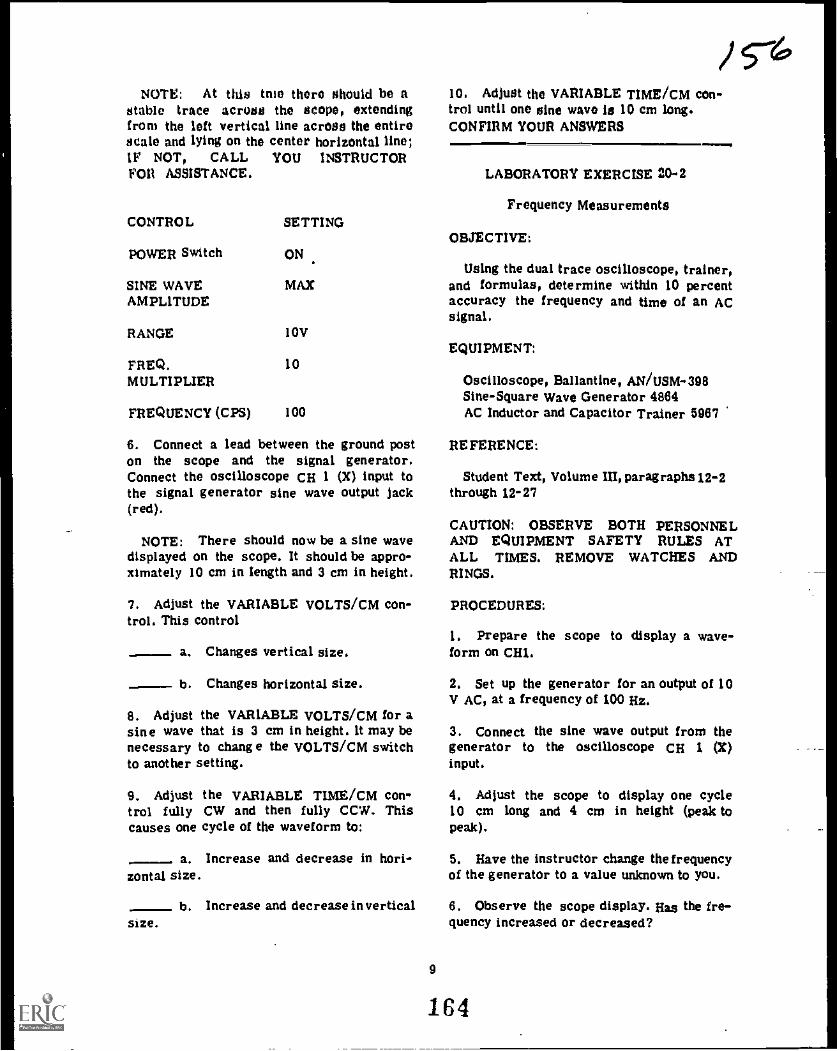
NOTE: At this true there shou1d be astable trace across the scope, extendingfrom the left vertical line across the entire/male and lying on the center horizontal line;W NOT, CALL YOU INSTRUCTORFOR ASSISTANCE.
CONTROL
POWER Switch
SINE WAVEAMPLITUDE
RANGE 10V
FREQ. 10MULTIPLIER
FREQUENCY (CPS) 100
SETTING
ON
MAX
6. Connect a lead between the ground poston the scope and the signal generator.Connect the oscilloscope CH I (X) input tothe signal generator sine wave output jack(red).
NOTE: There should now be a sine wavedisplayed on the scope. It should be appro-ximately 10 cm in Length and 3 cm in height.
7. Adjust the VARIABLE VOLTS/CM con-trol. This control
- a. Changes vertical size.
b. Changes horizontal size.
8. Adjust the VARIABLE VOLTS/CM for asine wave that is 3 cm in height. It may benecessary to change the VOLTS/CM switchto another setting.
9. Adjust the VARIABLE TIME/CM con-trol fully CW and then fully CCW. Thiscauses one cycle of the waveform to:
a. Increase and decrease in hori-zontal size.
size.b. Increase and decrease invertical
10. Adjust the VARIABLE TIME/CM con-trol until one sine wave is 10 cm long.CONFIRM YOUR ANSWERS
LABORATORY EXERCISE 20-1
Frequency Measurements
OBJECTIVE:
Using the dual trace oscilloscope, trainer,and formulas, determine within 10 percentaccuracy the frequency and time of an ACsignal.
EQUIPMENT:
Oscilloscope, Ballantine, AN/USM-398Sine-Square Wave Generator 4864AC Inductor and Capacitor Trainer 5967
REFERENCE:
Student Text, Volume III, paragraphs 12-2through 12-27
CAUTION: OBSERVE BOTH PERSONNELAND EQUIPMENT SAFETY RULES ATALL TIMES. REMOVE WATCHES ANDRINGS.
PROCEDURES:
1. Prepare the scope to display a wave-form on CHI.
2. Set up the generator for an output of 10V AC, at a frequency of 100 Hz.
3. Connect the sine wave output from thegenerator to the oscilloscope CH I (X)input.
4. Adjust the scope to display one cycle10 cm long and 4 cm in height (peak topeak).
5. Have the instructor change the frequencyof the generator to a value unknown to you.
6. Observe the scope display. Has the fre-quency increased or decreased?
9
164

'I. Set the VARIABLE TIME/CM control toCAL.
8. With the TIMF /CM control, make onecycle of the waveform as close to 10 cm aspossible, but not any more than 10 cm.
O. How many cm are there per cycle?
10. Using the formula "TIME of Cycle se
Number of cm x T1ME/CM setting," solvefor the time of one cycle.
TIME n sec.
11. Using the time of one cycle and theformula f 2 l/t, solve for frequency.
f u
CONFIRM YOUR ANSWERS
LABORATORY EXERCISE 20-3
Phase Measurements
OBJECTIVE:
Using the dual trace oscilloscope, trainerand formulas, determine within 10 percentaccuracy the phase angle between two ACsignals of the same frequency.
EQUIPMENT:
Oscilloscope, Ballantine, AN/USM-398
Sine-Square Wave Generator 4864
AC Inductor and Capacitor Trainer 5967
REFERENCE:
Student Text, Volume 11:1, paragraphs 12-28through 12-30.
CAUTION: OBSERVE BOTH PERSONNELAND EQUIPMENT SAFETY RULES ATALL TIMES. REMOVE WATCHES ANDRINGS.
10
/s7PROCEDURES:
I. Ground the sine wave generator to theoscilloscope. Connect the 4,04 1" probe tothe output jack of the sine wave generator.Adjust the size of the sine wave to 3 cmin height and position it in the top half ofthe graticule.
2. Make these scope control setticla:
CONTROL SETTING
CH 2 AC- GND -DC AC
CHOP-ALT ALT
I(CH 2 Vertical)
TRIO SELECT
So that CH2 trace is inlower half of thegraticule.
EXT }
3. Make these settings on the generator:
CONTROLFREQUENCYSINE -WAVEAMPLITUDERANGE
SETTING300 HzFully CW
10V
4. Connect a lead from the EXT TRIGjack on the scope to the CH2 (Y) jackusing a BNC connector.
5. Connect a wire from the CH 2(Y) inputto the output jack of the sine wave gene-rator. There should now be a stable display.
6. Set the CH2 display to 3 cm in height.What controls are used to make this adjust-ment?
7. Set the length of the sine wave CHI andCH2 to exactly 8 cm. What control makesthis adjustment?
8. Position the CHI signal over the CH2signal. Adjust the VARIABLE VOLTS/CMcontrols so that each signal is exactly 3cm high.
105

O. What phaso relationship is now indi-cated by the display?,
WW1
GEM
C.
min CH1 CH2
Figure 1-1
VATTIC
OND
10. Using the trainer, construct the circuitshown in figure 1-1.
11. The RC network will cause the CHIwaveform to (lead)(lag) the CH2 waveform.
12. Adjust the CH1 and CH2 VOLTS/CMand VARIABLE controls until the two signalsare 6 cm in amplitude and appear some-what like figure 1-2.
INEWAIWidVAIMITARFAWMTAL
1111MME111.Figure 1-2
13. The distance between the like pointson the CHI and CH2 waveform on the oscil-loscope is cm.
14. The length of one cycle of the CH2waveform is cm.
15. Determine the phase difference betweenthe two waveforms using the equation:
Phase Distance between wavesx 360°Difference Length of one cycle
16. The phase difference isdegrees.
CONFIRM YOUR ANSWERS
11
/s-CONSULT YOUR INSTRUCTOR FOR THEPROGRESS CHECK.RETURN TO TILE RESOURCE FROMWHICH YOU CAME AND CONTINUEWITH THAT PROGRAM.
YOU MAY STUDY ANOTHER RESOURCEOR TAKE THE MODULE SELF-CHECK.
LABORATORY EXERCISE 20-4
Oscilloscope Voltage Measurements
OBJECTIVES:
Using the oscilloscope, measure the amp-litude of an AC voltage and the amplitudeof a DC voltage.
EQUIPMENT:
Oscilloscope, Ballantine, AN/USM-398
Sine-Square Wave Generator 4864
DC Power Supply 4649
Multimeter PSM-13
REFERENCES:
Student Text, Volume M,paragraphsI2-31through 12-37.
CAUTION: OBSERVE BOTH PERSONNELAND EQUIPMENT SAFETY RULES ATALL TIMES. REMOVE WATCHES ANDRINGS.
PROCEDURES:
A.Measuring an AC voltage.
1. Set up the scope.
CONTROL SETTING
POWER ON
VOLTS/CM CH1 (X) IV
TRIG SELECT CH 1 +
LEVEL (Red) AUTO
166

CONTROL SETTINO remain connected to the output of the gene-rator for ?Raps 4 through 8,
AC-OND-DC CH1 AC4. Oround the signal generator to the oscil-
TIME/CM .5 mS loscope.
CH 2 (Y) OFF 5. Connect this signal into the CH I (X)input of the sCOpt,
2. Calibrate CH 16. Position the display for ease of reading
a, Connect a lead from the CAL 1 V the peak to peak amplitude.output jack to the CH1 input jack.
b. Adjust the VARIABLE VOLTS/ CM untilthe square wave on the scope is exactly 1cm in amplitude.
a. The signal is -- cm peakto peak.
b. The peak to peak voltage amplitude ofthe sine wave is ...
C. How many volts per cm are nowdisplayed on the scope? c. Calculate the effective voltage value of
this sine wave ,......,IMPORTANT: THE VARIABLE CONTROLMUST NOT BE movEr FROM THIS d. The difference in the PSM -6 readingSETTING. and the calculated effective voltage value
above was --...- ...
d. Move the CH1 VOLTS/CM control to.5V. 7. increase the signal generator output to
10 volts as measured by the PSM-6.(1) How many cm in height is the
square wave? 8. Make the necessary Position and VOLTS/CM adjustments to display the sine wave
(2) How many volts are there in each within the graticule and yet be easycm? to measure.
(3) What is the peak to peak ampli-tude of the square wave?
a. What is the number of cmspeak? =.. peak to
e. Move the VOLTS/CM control to 2V. b. peak to peak voltage is .
(1) How many cm in height is the c. Effective voltage issquare wave?
9. Disconnect the signal generator.(2) How many volts are there in each
cm? CONFIRM YOUR ANSWERS
(3) What is the peak amplitude of the B. Measuring Dc Voltage.square wave?
1. Set the DC Power Supply up for a 10-(4) Remove the end of the lead from volt reading on its output meter.
the CAL 1 V output jack.2. Set the CH 1 ACGNDDC control to DC.
3. Set up the signal generator for a 1 kHz,3V output sine wave. Use the PSM-6 to 3. Position the scope trace on the bottommeasure this voltage. The PSM-6 should horizontal line.
12 1C7
/

4, around the black jack of the power 7. Have the instructor set up a differentsupply to the oscilloscope. value of DC voltge.
5. Set the VOLTS/CM to 2.
6, Connect the power supply 4. post (red) 8. Adjust the VOLTS/CM switch as required.to the CH 1 (X) input jack on the scope.using a BNC connector and a conductor.
a, What happened to the trace? 9, What is the DC voltage value?
b, How far did it move?CONFIRM YOUR ANSWERS
CONSULT YOUR INSTRUCTOR FOR THEc. What is the value of the DC voltage PROGRESS CHECK.
as indicated by the scope?YOU MAY STUDY ANOTHER RESOURCEOR TAKE THE MODULE SELF-CHECK.
MODULE SELF-CHECK
QUESTIONS:
1. Match each control with its function.
a. VARIABLE VOLTS/CM (Red)
- b. TIME /CM
c. CHOP-ALT
- d. CHIT
e.
- f. VOLTS/CM
VARIABLE T1ME/CM (Red)
h. CH1 AC-GND-DC
i. FOCUS
J. CAL 11,
1. Selects desired attenuation of the inputsignal.
2. Provides intermediate adjustment ofattenuation between settings of the VOLTS/CMSWITCH.
3. Provides intermediate adjustment of sweeprate between settings of the TimP / cm switch.
4. Selects desired sweep speed.
5, Controls the location of the trace withrespect to the X axis.
6. Selects the desired calibrated square wave.
7. Adjusts vertical position of CHI display.Switches CHI off on OFF detent.
8. Selects capacitive or direct coupling ofthe input signal or grounds out the input toestablish a reference.
9. Adjusts for a clear, sharply defined trace.
10. Selects CHOPPED, or ALTERNATE fordual trace vertical deflection.
13
168

2. VARIABLE TIME /CM (Red) is sot toCAL and the T1ME/CM control is set to5 mS. An AC signal is displayed on thescope and the length of one alternation is2 cm. What is the frequency?
a, 50 Hz
c. 150 Hz
.---- b. 10 Hz
, d, 200 Hz
3, Which of the following scope presenta-tions display a 90° phase difference?
REP4.-1112
4. The VARIABLE VOLTS/CM (Red) is setto CALIBRATE and the VOLTS/CM controlis set on 5. An AC signal is displayed asindicated. What is the effective voltage?
.111 a. 7.07 volts b, 10.6 volts
c. 15.2 volts d. 30 volts
REP4..2224
lo5, VARIABLE TIME/CM (Red) is set toCALIBRATE and the TIME/CM control isset to 20 uS. An AC signal is displayedas indicated. What is the frequency?
a. 8.33 kHz ---. b. 12.5 kHz
..... c. 25 kHz .---. d, 50 kHz
RtP4 -1115
6. Which of the following scope presen-tations display a 180° phase difference?
--- a f\ b
mac. _____d.
REP4-1113
14 169

7. The VARIABLE VOLTS/DIV (Red) is setto CALIBRATE and the VOLTS/DIV controlis set on 3. An AC signal is displayed asindicated. What are the effective and peakvoltages?
a. 1.4 volt effective, 2 volts peak
b. 2.8 volts effective, 4 volts peak
CONFIRM YOUR ANSWERS
c. 4.2 volts effective, 8 volts peak
d. 8.4 volts effective, 12 volts peak
K111011111111=111111=1011111111111MINIMIEMENta
15
170

ANSWERS TO A - ADJUNCT GUIDE
1.2.3.
bba
If you missed ANY questions, reviewthe reference material before youcontinue.
ANSWERS TO C - ADJUNCT GUIDE
1. 200 Hz2a. 10 cm2b. 5cm2c. 2cm3. 22.5
If you missed ANY questions, review thereference material before you continue.
ANSWERS TO E - ADJUNCT GUIDE
1. 7V peak-to-peak2. 7.07 V3. 2.828 cm
U you missed ANY questions, review thereference material before you continue.
ANSWERS TO LAB EXERCISE 20-1
2a. 5 b. 10f. 3 g. 7
3. A-21 B-22F-19 G-15K-18 L-14p-3 Q-6U-9 V-10
c. 9h. 2,
C-11H-16M-1R-5
d. 4 e. 8i. 6 j. 1
D-20 E-121-17 J-13
N-2 0-4S-7 T-8
U you missed any items, review thereference material before you continue.
ANSWERS TO B (20-1)
7. a9. a
U you missed ANY questions, ask yourinstructor for assistance.
16
--ANSWERS TO LAB EXERCISE 20-1
Have your instructor check your answersfor questions 6, 0, 10, and 11.
For more practice on this part of theexercise, repeat steps 5 through 11.
U you missed ANY questions, ask yourinstructor for assistance.
ANSWERS TO LAB EXERCISE 20-3
8. CH2 VOLTS/CM and VARIABLE7. TIME/CM and VARIABLE9. The two signals are in phase.
11. Lead14. Have your instructor check your
answer.16. Have your instructor check your
answer.
NOTE For more practice on measuringthe phase angle between two signals, haveyou instructor give you different capa-citor and/or resistor, and/or appliedfrequency values.
U you missed ANY questions, ask yourinstructor for assistance.
ANSWERS TO A - LAB EXERCISE 20-4
2c. 1 volt/cm2d(1) 2 cm (2) .5 volts /cm (3) 1 volt2e(1) .5 cm (2) 2 volts/cm (3) 1 volt6. Have instructor verify.8. Have instructor verify.
U you missed ANY questions, ask yourinstructor for assistance.
ANSWERS TO B LAB EXERCISE 20-4
6a. The trace is displaced upward.6b. 5 cm (approximately)6c. 10V (approximately)9. Have instructor verify.
If you missed ANY questions, ask yourinstructor for assistance.
171
4.5

4r
ANSWERS TO MODULE SELF-CHECK
la, 2 b. 4C. 10 d. 7e.g.
5
3
f,h.
I8
i. 9 1. 82. a3. e4. b5. b8. d7. e
/61HAVE YOU ANSWERED ALL OF THE
QUESTIONS CORRECTLY? IF NOT
REVIEW THE MATERIAL OR STUDY
ANOTHER RESOURCE UNTIL YOU CAN
ANSWER ALL QUESTIONS CORRECTLY.
IF YOU HAVE, CONSULT YOUR
INSTRUCTOR FOR FURTHER GUIDANCE.
17
172

ATC GP 3AQR3X020-X
ATC K** get 6.2556
Technical Training
ELECTRONIC P RI NCI PL ES
MODULE 21
December 1975
AIR TRAINING COMMAND
7- 7
Designed Fot ATC Course Use
DO HOT USE ON THE JOI
173
KEP GP-21

Radar Principles BranchKees ler Air Force Base, Mississippi
ATC GP 3AC)113X020-XKEP-GP-21
December 1975
ELECTRONIC PRINCIPLES (MODULAR SELF-PACED)
MODULE 21
SERIES RCL CIRCUITS
This Guidance Package is designed to guide you through this module of the ElectronicPrinciples Course. It contains specific information, including references to other resourcesyou may study, enabling you to satisfy the learning objectives.
CONTENTS
Title
OverviewList of ResourcesAdjunct GuideLaboratory Exercise 21-1Module Self-CheckAnswers
OVERVIEW
1. SCOPE: This mxiule expands on yourknowledge of capacitors, coils, and resistorsas they apply to RCL circuits. You willcompute the voltage drop, current, phaseangle, impedance, and power factor for RCLcircuits. Practical training is provided forexamining the relationships that existbetween the circuit parameters.
2. OBJECTIVES: Upon completion of thismodule, you should be able to satisfy thefollowing objectives.
a. Given a series RCL circuit with appliedvoltage, total current, resistance values, andformulas, solve for true power and apparentpower.
b. Given a series RCL circuit with com-ponent values, applied voltages. andfrequency indicated, calculate the values ofand plot the vectors for:
Page
Ii1
8
1114
(1) Total impedance.
(2) Total current.
(3) All voltages.
(4) Approximate phase angle.
c. Using an oscilloscope and trainer,determine relative amplitude and phase re-lationship of Ea, ER, EL, and EC in a seriesRCL circuit.
LIST OF RESOURCES
To satisfy the objectives of this module.you may choose, according to your training,experience, and preferences, any or all ofthe following:
READING MATERIALS:
Digest
Adjunct Guide with Student Text III
Supersedes KEP-GP-21, 1 July 1975. Existing stock may be used.
i
174
A
MEW

/V /AUDIOVISUALS: 2. What is the phase relationship between
current and applied voltage in:TV100-257, Series RC Circuits
TVX30-258, Series RI, Circuits
LABORATORY EXERCISE:
21-1, Series RCL Circuits
SELECT ONE OF THE RESOURCESAND BEGIN YOUR STUDY OR TAKETHE MODULE SELF-CHECK,
CONSULT YOUR INSTRUCTOR IF YOUREQUIRE ASSISTANCE.
ADJUNCT GUIDE
INSTRUCTIONS:
Study the referenced materials as directed.
Return to this guide and answer thequestions.
Confirm your answers in the back of thisGuidance Package.
If you experience any difficulty, contactyour instructor.
Begin the program.
A. Turn to Student Text. Volume UI, andread paragraphs 1-1 through 1-8. Returnto this page and answer the followingquestions.
1. Define impedance.
a. A purely resistive circuit.
b. A purely capacitive circuit.
c. An RC circuit.
CONFIRM YOUR ANSWERS.
B. Turn to Student Text, Volum.? UT. andread paragraphs 1-7 through 1-11. Returnto this page and answer the followingquestions.
1. Define vector.
.
2. What is the difference between apositive
and a negative angle?
1
175

3. Label the vectors in this diagram for anRC circuit.
O. Ilr
REP -1030
CONFIRM YOUR ANSWERS.
C. Turn to Student Text, Volume III, andread paragraphs 1-12 through 1-18. Ret. ...it
to this page and answer the followingquestions.
1. Write the Pythagorean Theoremformulas for finding each side of the righttriangle shown.
REP4 1032
2
2. Solve for c in this triangle.
12
6
16REP4103,
C--
3. Solve for a in this triangle.
b 63 cmREP44034
a=
CONFIRM YOUR ANSWERS.
D. Turn to Student Text, Volume III, andread paragraphs 1-19 through 1-27. Returnto this page and answer the followingquestions.
1. Using the table in KEP-110, find:
a. The sine of:
(1) 30°.
(2) 45°.
(3) 60°..
b. The cosine of:
(1) 75°.
(2) 45°.
(3) 60°.
176
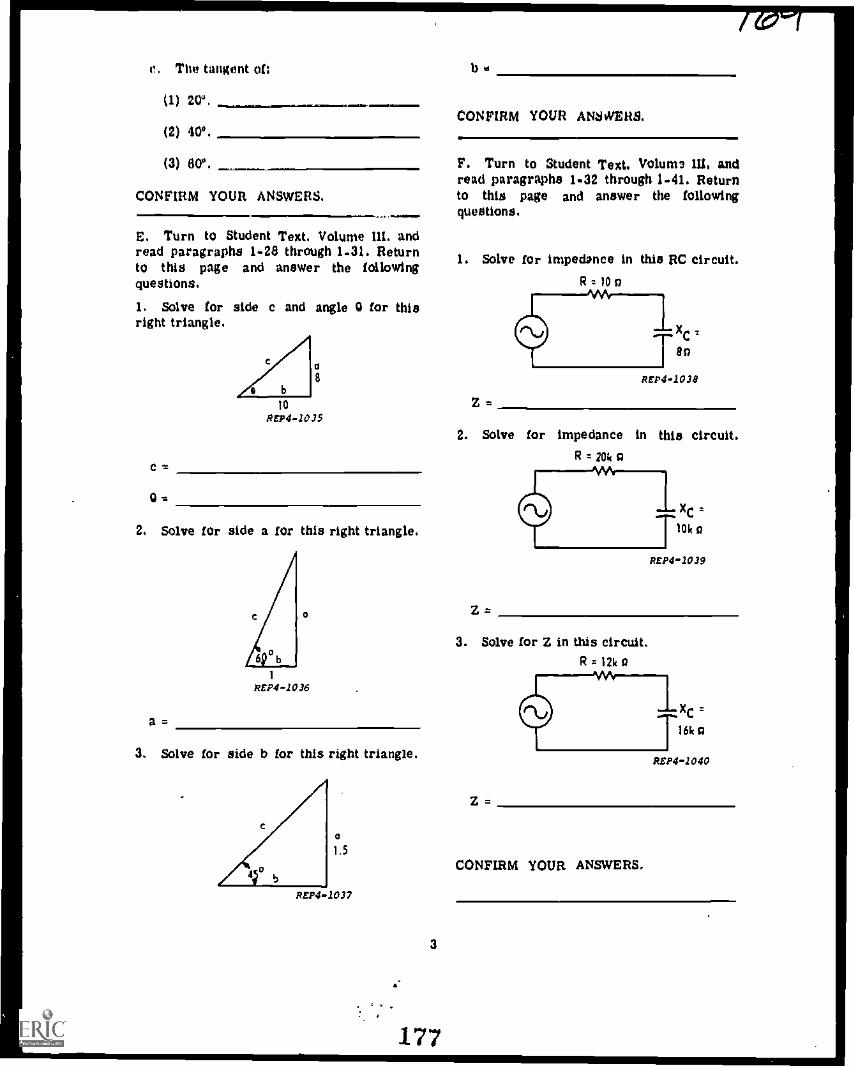
e. The tangent of
(1) 20*.
(2) 40.
(3) 6V.
CONFIRM YOUR ANSWERS.
E. Turn to Student Text. Volume ill. andread paragraphs 1-28 through 1-31. Returnto this page and answer the followingquestions.
1. Solve for side c and angle 0 for thisright triangle.
C
0=
1014104-1015
2. Solve for side a for this right triangle.
a=
1
REPS -1036
3. Solve for side b for this right triangle.
a1.5
REP4 -1037
3
177
CONFIRM YOUR ANSWERS.
F. Turn to Student Text. Volurn 10, andread paragraphs 1-32 through 1-91. Returnto this page and answer the followingquestions.
1. Solve for impedance in this RC circuit.R 10
2. Solve for impedance in this circuit.R = 2ok a
3. Solve for Z in this circuit.R 12k o
Xc
10k o
REP41039
CONFIRM YOUR ANSWERS.
Xc
16k a
REP4 -1040

G. Turn to Student Text, Volume HI, andread paragraphs 1..42 through 1-52. Returnto this page and answer the followingquestions.
I. Using the values given in the circuitdiagram, solve for the listed values. Plotthe impedance and voltage vectors,
Z 4.
Ea
Enz.-
AI.
EC =
0=40k0
30ko
Aw-------30ewREPO -1041
2. Solve for the indicated values. Draw thevoltage and impedance vectors.
no
26.5 HzREP4-..1042
I=
ER =
Ec =
0 =
CONE :AM YOUR ANSWERS.
4
H. Turn to Student Text, Volume Ill, andread paragraphs 2-1 through 2-0. Return tothis page and answer the following questions.
I. In a purely inductive circuit, What is thephase relationship between the circuit
current and applied voltage?
2. In a resistance inductance circuit, whatis the phase relationship between currentand the:
a. Applied voltage?
b. Inductor voltage?
c. Resistor voltage?
3. Choose the vector diagram which repre-sents the phase relationships in an RLcircuit.
a.
b.
c.
d.
173
/7o
Ma.

4. Plot the impedance vector diagram for an
ItL circuit in which XL 111,
CONFIRM YOUR ANSWERS.
I. Turn to Student Text, Volume III, andread paragraphs 2-7 through 2..10. Return tothis page and answer the following questions.
1. Use the values given to splve for thelisted items. Draw the impedance and voltagevector diagrams.
Z
I
ER =
EL=
0
R = 30k0
XL=
50kg
REPO -1046
2. Solve for indicated values. Draw impedanceand voltage vectors
XL-
I =.
ER =
EL=
8=
R 50g
Replaces pages 5 and 6. KEP-GP 21
Arc Kooks /4264
L 12 mH
REP4*1047
5
179
CONFIRM YOUR ANSWERS.
J. Turn to Student Text, Volume III, andread paragraphs 2-11 through 2-18. Return tothis page and answer the following questions.
I. what is the phase relationship betweenXL and Xc?
2. Draw the impedance vector diagram forthis circuit.
31E1 kHz
81c ohms
= 5k ohms
R 4k0
REPO -10S1
CONFIRM YOUR ANSWERS.
K. Turn to Student Text, Volume 111, andread paragraphs 2-17 through 2-28. Return tothis page and answer the following questions.
1. Solve for each of the listed items. Drawthe voltage vector diagram. BkR
I
ER =
EL=Er
318 kHz4k0
SkoREPO -2009

3. What is the average power in a purely
capacitive circuit?
2. Solve for the unknown values. Draw the 4. What Is the average power of a purelyimpedance and voltage vector diagrams.
Z
1
24ka
CONFIRM YOUR ANSWERS.
10ka
41214a
RtP4.1050
L. Turn to Student Text, Volume III, andread paragraphs 3-1 through 3-16. Return tothis page and answer the following questions.
1. Define power.
2. What is power in terms of current andvoltage?
inductive circuit?
6
5. What is the term used to describe powerin a purely capacitive or a purely inductive
circuit?
CONFIRM YOUR ANSWERS.
M. Turn to Student Text, Volume III, andread paragraphs 3-17 through 3-23. return tothis page and answer the following questions.
1. Define true power
Igo
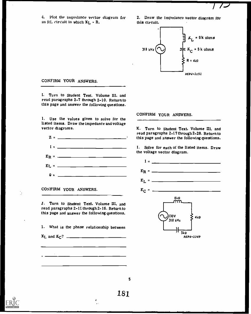
4. Plot tlir impedance vector diagram for 2. Draw the impadance vector diagram foran Rt. circuit in which XL, - It
CONFIRM YOUR ANSWERS.
I. Turn to Student Text. Volume III, andread paragraphs 2-7 through 2-10. Return tothis page and answer the following questions.
1. Use the values given to solve for thelisted items. Draw the impedance and voltagevector diagrams.
Z=
1=
ER =
Et. .
0=
CONFIRM YOUR ANSWERS.0111.01..
J. Turn to Student Text, Volume Ul, andread paragraphs 2- I i through 2-16. Return tothis page and answer the following questions.
1. What is the phase relationship between
XL and XC?
5
181
this circuit.
310 kHz
± Ok ohms
a 5k ohms
R = 410
REP4-1051
CONFIRM YOUR ANSWERS.
K. Turn to Student Text, Volume III, andread paragraphs 2-i7 through 2-28. Returntothis page and answer the following questions,
I. Solve for each of the listed items. Drawthe voltage vector diagram.
I=
ER =
EL =
EC =
Oka

2. Solve for the unknown values. Draw theimpedance and voltage vector diagrams,
Z
I
EC
EL a
ER a
421.o
REP4 -1050
CONFIRM YOUR ANSWERS.
3. What is the average power in a purely
capacitive circuit?
4. What is the average power of a purely
inductive circuit?
5. What is the term used to describe powerin a purely capacitive or a purely inductive
L. Turn to Student Text. Volume M. andread paragraphs 3-1 through 3-16. Return to circuit?this page and answer the following questions.
1. Define power.
2. What is power in terms of current and
voltage?
6
CONFIRM YOUR ANSWERS.
M. Turn to Student Text, Volume M. andread paragraphs 3-17 through 3-23. Return tothis page and answer the following questions.
1. Define true power.
182

2. Define apparent power and give the unit
in which it is expressed.
------...
3. Determine Pt and Pa for these circuits.
a. Pt =Pa
R : 4kg
b. Pt a
Pa
XL. z 4k o
c. Pt =
Pa =
XC .6ko
CONFIRM YOUR ANSWERS.
XL. = 6ko
REP4 -1054
N. Turn to Student Text, Volume III, andread paragraphs 3-24 through 3-32. Return tothis page and answer the following questions.
I. Label the PREACTIVE, Pt, and Pa vec-tors in the power vector diagram. Theimpedance vectors are given as a reference.
7
183
Ay.111111.
OP
2. Solve for the indicated values in thisproblem.
Z is
1=
ER
EC= ----.0 =
Pte
Pa
m.....
REP4-1056
3. Solve for the indicated values.
Z =_
1=
ER =
EL =
0=
Pt a
Pa =
REP4 -1057

4 Solve for the Indicated values.
Z
ER rt
EL z-
.111MilmMIMM
E C
0=
Pt 2
Pa
. 3 mA soREPO -1058
CONFIRM YOUR ANSWERS.
0. Turn to Laboratory Exercise 21- I. Inthis exercise you will be working with aseries RCL circuit, measuring componentvoltages and determining phase relationships.........
Y01.1 MAY STUDY ANOTHER RESOURCEOF. TAKE THE MODULE SELF-CHECK.
LABORATORY EXERCISE 21-1
OBJECTIVE: Using an oscilloscope andtrainer, determine the amplitude of Ea, ER,EL. and EC, and determine the phase rela-tionship of each of the voltages in a seriesRCL circuit.
EQUIPMENT:
Oscilloscope, Ballantine. AN/USM-398AC Inductor and Capacitor Trainer. 5967
8
/9lIsolation Transformer, 6124Sine Square Wave Generator, 4864
REFERENCE:
Student Text, Volume III, paragraphs 3-1through 3-32
CAUTION: OBSERVE BOTH PERSONNELAND EQUIPMENT SAFETY RULES ATALL TIMES. REMOVE WATCHES ANDRINGS.
PROCEDURES:
A. Measure circuit voltages.
I. Set the following scope controls:
CONTROL
POWER
VOLTS/CM
CHI AC-GND-DC
CHI Vert. Pos.
CHOP-ALT
AC ACF-DC
LEVEL
TRIG SELECT
TIME / CM
SETTING
ON
0.5, CAL
AC
Mtdposition
ALT
AC
AUTO
CHI +
0.2 mS, CAL
2. Connect the CHI input to the output ofthe isolation transformer and the scopeground to the other output terminal of theisolation transformer.
3. Connect the input of the isolation trans-former to the sine wave output of thegenerator.
4. Set the gener ,tor for a 3 kHz output thatis 4 cm high on the scope.
184

1A
3 kHz
ISOLATIONTRANSFORMER
L102.5 ti
R103
CII;
2
1k15.01 ILF 7
tQ
5. What is the peak to peak amplitude of
the signal? volts.NOTE: This will be the Eato the RCL circuit.
6. Connect the circuit as shown in thediagram at the top of this page.
7. Which component voltage is being viewed
on the scope?
8. What is the peak to peak value?
9. Move the scope ground lead to point Dand the CHI input to point C.
10. What is the peak to peak value of EC?
volts. 4. Connect CH1 input to point A in thecircuit.
RSP4 -1060
B. Phase relationships.
1. Connect the scope as shown in the figureat the bottom of this Page.
2. Make these scope adjustments:
CONTROL
TRIG SELECT
CH2 AC-MID-DC
CH2 Vert. Pos.
SETTING
EXT +
AC
Midposition
3. Connect EXT TR1G to point A in thecircuit.
11. Move the scope ground lead to point Cand the Clil input to point B.
12. What is the peak to peak value of ER? Itmay be necessary to change the VOLTS/CM
setting to get a clear reading. _ volts.CONFIRM YOUR ANSWERS.
e3 kHz
H
5. Connect scope ground to point D in thecircuit.
6. Connect the CH2 input to point C.
7. Turn CH2 unUl a second signal is viewedon the screen.
L102.5 H
R1031.2k
d101.31 oF
I ZVI
CA1 C.117 CND
185
9

8. Adjust the TIME/CM switch and theVARIABLE control so one sine wave isexactly 8 cm long.
9. Adjust the scope controls so that the twosignals are equal in amplitude.
10. What voltage is displayed on CH1?
11. What voltage is displayed on CH2?
12. Is EC in phase with Ea? Channel 1 is
displaying Ea.
13. How many centimeters separate the two
signals?
14. What is the phase difference between
the two signals? degrees.
CONFIRM YOUR ANSWERS.
/ nr
15. To compare Ea and EL, reconnect thecircuit as shown in the above illustration.
18. Adjust the scope so EL and Ea have thesame amplitude and one sine wave is 8 cmlong.
17. The phase difference between the two
signals is cm Or
degrees.
CONFIRM YOUR ANSWERS.
18. Set up the circuit shown at the bottom ofthis page to compare ER with Ea.
19. Adjust the scope so ER and Ea have thesame amplitude and one cycle is 8 cm long.
20. The phase difference between the two
signals is cm or
degrees.
21. Disconnect the equipment.
CONFIRM YOUR ANSWERS.
10186
Alm

CONSULT YOUR INSTRUCTOR FOR THE ER aPROGRESS CHECK.
EL
PtYOU MAY STUDY ANOTHER RESOURCEOR TAKE THE MODULE SELF-CHECK.
MODULE SELF-CHECK
1. Solve for:
Z
I=
ER
EC
Pt
Pa =
0=
Draw the impedance vectors.
2. Solve for:
Z
=
REPO -2064
Pa a
0a
READ4..1065
Draw the voltage vectors using Ea as thereference.
3. Solve for:
XC
Z
I=
ER =
EC
Pt
Pa
=
11
187
6W159 Hz
12k a
C.2 $LF
REP4 -1066

/ &I
Draw the voltage vectors using Ea as the 5. Solve for:reference.
XL 2
xc )2
Z2
l=
EL 2
EC a
4. Solve for: ER a
Z = 0 a
I
ERn
EL a
0=
Pt -7
Pa=
w11.1.a..
REP4-1067
Draw the impedance vectors.
12,
Pt 11...11M
MIMI.,11111,...
Pa
R
3k n
20V C159 HI .0909 iLF
L
15 H
Draw the impedance vectors.
188
REP4-1068
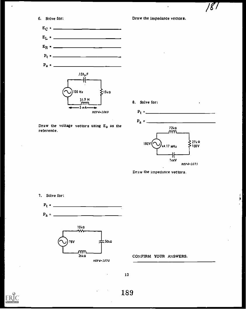
O. Solve tor:
EC a
EL a
ER.
Pt a
Pa*
.159 F
100 Hi
31.9 H
de---5 mA--4,REPO -1069
Draw the voltage vectors using Ea as thereference.
7. Solve for:
Pt'Pa =
1014o
50kg
Draw the impedance vectors.
8. Solve for:
Pt =
Pa '
180V
7214o
27140108V
1 4 4V
REPO -.107J
Draw the impedance vectors.
26k0 CONFIRM YOUR ANSWERS.REPO -1070
13
189

ANSWERS TO A - ADJUNCT GUIDE: 2. 20
1. Impedance is the total opposition offered 3. 25 cmto the flow of alternating current.
2. a. Current and voltage are in phase.
b. Current leads the voltage by 90°.
c. Current leads the voltage by lessthan 90°.
If you missed ANY questions. review thematerial before you continue.
ANSWERS TO B - ADJUNCT GUIDE:
If you missed ANY questions. review thematerial before you continue.
ANSWERS TO 0 - ADJUNCT GUIDE:
1. a.
b.
c.
(I) .5000
(1) .2588
(1) .3640
(2)
(2)
(2)
.7071
.7071
.8391
(3)
(3)
(3)
.8660
.5000
1.7321
If you missed ANY questions. review the1. A vector is a line used to represent material before you continue.magnitude and direction.
2. A positive angle is generated when a ANSWERS TO E - ADJUNCT GUIDE:vector is rotated CCW.
1. c = 12.8 0 = 38.7°A negative angle is generated when a
vector is rotated CW. 2. a = 1.7321
3. ER 1 3. b = 1.5
EC
REPO -2031
U you missed ANY questions, review thematerial before you continue.
U you missed ANY questions, review thematerial before you continue.
ANSWERS TO F - ADJUNCT GUIDE:
1. Z= 12.81 ohms
2. Z = 22.4 k ohms
3. Z = 20 k ohms
If you missed ANY questions, review theANSWERS TO C - ADJUNCT GUIDE: material before you continue.
1.
1p4:c = a b
2
-F-.a = c - b2
-F2b = c -
14
ANSWERS TO 0 - ADJUNCT GUIDE:
1. Z = 50 k ohms
Ea = 150V
ER = 120V
190
OM.

M 00V
U 2 3000°
36.9°
11 you missed ANY questions, review thematerial before you continue.
R 40ko
ANSWERS TO H - ADJUNCT GUIDE:
1. Current lags the applied voltage by 90°.
XC 0-3 ko2. Current lags the applied voltage by less
Z 2 50ko than 90°.
7VER 2 120
<1 r. 3 InA
36.9°
C 99v
2. Z 2 10 k ohms
XC = 6 k ohms
I z 10 mA
ER 2 80V
EC = 60V
0 = 36.9°
.. Ee 2 150v
R = 8ko
36.9°
E
XC z 6ko Z 2 10k o
ER = 80v7I »10mA
36.9°
EC z 60V
Current lags EL by 90°.
Current and ER are in phase.
3. d
4.
U you missed ANY questions, review thematerial before you continue.
ANSWERS TO I - ADJUNCT GUIDE:
1. Z = 58 k ohms
I 2 mA
ER = 60V
EL = 100V
0 - 58.9°
=100V X 50k*Z = 581c4
ArP4 -2043
15
191
93.9°,rR -3ct
E 100v
ER 260V
2116v

2, XL 120 ohms
Z 130 ohms
1 2 A
ER MyEL a 240V
0 a 67.4°
XL 11200 Z 2 130g
R = 500
I =2A
ER = 100V
RSP4..1048
r-' 240V
swEo = 260V
If you missed ANY questions, review thematerial before you continue.
ANSWERS TO J - ADJUNCT GUIDE:
1. XL and XC are 180° out of phase.
2. xL =Bko
xL -XC = 5k fa
3k0 R : 4k0
36.9°
xC = 5'kg
REPO -105 ;"
If you misted ANY questions, review thematerial before you Continue.
ANSWERS TO K - ADJUNCT GUIDE:
1. I= 20 ma /36.9°
ER a 80V /-36.9°
EL = 160V A63.1°
Ec 21 100V 1-126 9°
16
EL :160V it al
osEa 1 100V ZOL,/ER 2 80V /...aLe.
Ec 100V /-126.9°,
2. Z =40kohms
I 3 oiA
EC = 126V
EL = 30V
ER u 72V
xC -XL32k
XL = 10k g
53.1° R = 24k g
1
mA A/o
c = 42kfa
40k9
ER = 72V
EL = 30V 1 = 3 inA
53.1° Ea
/ 120V
Ec s 126V
REP4 -2052
If you missed ANY questions, review thematerial before you continue.
192

ANSWERS TO L ADJUNCT GUIDE: 2. Z 20 k ohms
1. power is rate of doing work. 1 * 4 mA
2, P4 1xE ER 64V
3. The average power in apurely capacitive EC = 48Vcircuit is zero.
0 * 36.9°4. Zero
Pt = 256 mW5. Apparent power
Pa= 320 mVA
If you missed ANY questions, review the 3. Z 2.6 k ohmsmaterial before you continue.
1= 20 mA
ANSWERS TO M - ADJUNCT GUIDE: ER = 48V
1. True power is the actual power disci- EL = 20Vpated by the circuit resistance.
0 = 22.6°
2. Apparent power is the product of current Pt = 960 mWtimes voltage. and is expressed in volt-amperes. Pa = 1040 mVA
3. a. Pt = 1.6W 4. Z = 28.28 k ohms
Pa = 2 VA ER = 60V
b. Pt = 675 mW EL = 120V
Pa = 1.125 mVA EC = 60V
c. Pt = 500 mW 0 = 45°
Pa = 500 mVA Pt = 180 mW
Pa = 254.52 mVAIf you missed ANY questions. review the
material before you continue.
ANSWERS TO N - ADJUNCT :2UIDE:
1. PREACTIVE
17
193
If you missed ANY questions,material before you continue.
V.(
review the
ANSWERS TO A - LAB EXERCISE:
5. 20V peak to peak
7. EL
8. Have instructor verify.

10. Have instructor verify.
11. Have instructor verify.
If you missed ANY questions, ask yourinstructor for assistance.
ANSWERS TO B - LAB EXERCISE:
10. Ea
11. EC
12. No
13. Have your instructor verify your answer.
14. Have your instructor verify your answer.
If you missed ANY questions, ask yourinstructor for assistance.
17. Have your instructor verity your answers.
U you missed any questions, ask yourinstructor for assistance.
20. Have your instructor verify your answers.
If you missed ANY questions. ask yourinstructor for assistance.
ANSWERS TO MODULE SELF-CHECK:
I, Z = 25 k ohms
EC = 24V
1 *1.2 InA
Pt= 21.6 mW
0 = 53.1°
ER . 18V
Pa = 36 mVA
V ...
Xc
23k fl
2. Z * 39 k ohms.
EL * 72V
I = 2 mA
Pt= 60 mW
0 = 67.4°
ER = 30V
Pa = 156 mVA
4*.R15in
IIM .1=1.
2
25kfl
REPO -1072
3. Xc = 5 k ohms
ER = 60V
Pa= 325 mVA
Z = 13 k ohms
EC = 25V
I = 5 mA
Pt = 300 mW
0 = 22.6°
18 194
PEP4-:,73

REP41074
4. Z 2 50 k ohms
EL = 120V
Pt = 640 mW
I=4mA
= 36.9°
Pa = 800 mVA
ER = 160V
5. XL = 15 k ohms
= 4 mA
ER = 12V
Pa = 80 mVA
XC = 11 k ohms
EL = 60V
0 = 53.1°
Z = 5 k ohms
EC = 44V
Pt = 48 mW
Z 50ko
R 40kQ
REPO -718
19
195
XL-XC4ko
6. EC = 50V
Pt = 375 mW
EL = 100V
Pa = 450 mVA
ER = 75V
Z Sko
R 3ko
REP4-72d
7. Pt = 90 mW
Pa = 234 mVA
- XL _
REP4 -1075
XL 26kg
lib R 10k a
--- Z 26k g
XC 50kt)
REP4 -1076

8. Pt 2 432 mW
Pam 720 mVAxL. 72ko
XL - Xc--
k 36ko
Z 4Sko
R 27ko
REP41077
20
HAVE YOU ANSWERED ALL OF THE
QUESTIONS CORRECTLY? IF NOT,
REVIEW THE MATERIAL OR STUDY
ANOTHER RESOURCE UNTIL YOU CAN
ANSWER ALL QUESTIONS CORRECTLY.
IF YOU HAVE, CONSULT YOUR IN.
STRUCTOR FOR FURTHER GUIDANCE.
190
/a

MISPARS INi, rT MAN
t PI
( ......r-- ,"'
Technical Training
1
ATC PT 3AOR3X020-Xttf4Prepared by Keesier TTC
KE12-12T-21
ELECTRONIC PRINCIPLES (MODULAR SELF-PACED)
MODULE 21
SERIES REACTIVE CIRCUITS(NONRESONANT)
1 January 1975
AIR TRAINING COMMAN D
7 -7Designed For ATC Course Use
00 NOT USE OH THE JO$

Stwie and Applied Elsotronics Department Programmed Text 3AQR3X020.XKessler Air Fords Base, Mississippi KBPPT.21
This illustrated Programmed Text is designed to in the studyof Series Reaotive Circuits. Etoh page contains an rtant idea orconcept to be understood before proceeding to the next. An iilustration for each objective is presented to clarify what is to be learned.
At the bottom of eaoh page, there are a few Twist/oho to bring outthe main poigTE-"Thess are indicated by....It is hoped that these questions also aid Q.1 or Q2 etc..understanding the subject a little better.
The answers) to these questions will be found on the tog of afollowing page, indicated as....Short comments say follow the I A1 or A2 etc..answers to help understand whya question may have been missed.
INDEX
Introduction & Impedance 1
Calculating Impedance 3Calculating Total Current 6Voltage Drops 7Reactive Circuit Power 10Apparent Power 11
True Power 12
Operating Characteristic 14Phase Angle 15
Equation Summary 20Circuit Problems 21
Vector DiagramsImpedance VectorsUsing Impedance VectorsVoltage-Current VectorsUsing Voltage VectorsVector Summary
Summary
OESJECTIVES
Upon completion of this module,you should be able to satisfy thefollowing objectives:
a. Given an AC series RCL circuitwith applied voltage, totalcurrent, resistance values,and formulas, solve for truepower and apparent power.
b. Given a series RCL circuitwith component values, appli-
22 ed voltage, and frequency26 indicated, calculate the32 values of and plot the vectors36 for46 (1) total impedance.
49 (2) total current.(3) all voltages.
5D (4) approximate phase angle.
c. Using an oscilloscope andtrainer, determine relativeamplitude and phase relationship of Ea, ER, EL, and EC, ina series RCL circuit.
i
198

INTRODUCTION,
Most electronic equipment is constructed of series and parallel con-nected "reactive" components, All audio and video circuits, operate esfrequency sensitive "reactive" circuits. Resistors, capacitors, and ind-uctor*, operating together, form the "heart" of complex receivers, trans-mitters, control and indicating assemblies.
Transistors and tubes depend upon proper "cooperation" between resis-tors, capacitors, and inductors, connected to their terminals. Failure ofsuch components to "react" properly together, will disable the entire cir-cuit, and result in "system" troubles often difficult to locate. The ser-vice technician must therefore have a "working knowledge" of how thesethree components control the performance of most Electronic circuits.
The study of how these components "work together" is called SeriesReactive Circuits. It is a complex and difficult subject, requiringseveral different approach.* to understand how the three electronic partsjoin their operating characteristics into "one" result.
This text is divided into two such "approaches". 1. The circuits.their theory of operation, and calculations. 2. Vector diagrams. and howto use them.
The study begins with "Impedance", and what it consists of.
IMPEDANCE
The total opposition, in any alternating current circuit, is called
EMDCIAN. (Symbol Z)
Most AC circuits are made up of
combinations of Resistance (R). Capacitive
Reactance (XC) , and Inductive
Reactance (XL). Lumped together,
these differing oppositions form a total called IMPEDANCE (Z).
As with all oppositions, IMPEDANCE is measured in oms.n. . k.46,
or M A.. EXAMPLE,: "The impedance of this circuit , &A.".
Q-1 a. The total opposition in any alternating current circuit. iscalled
b. The combination of Resistance and Reactance is called .
c. Impedance (Z) is the opposition of AC circuits.d. t- F.Impedance (Z) is measured in amperes.e. T-F.Impedance (Z) is measured in volts.f. Impedance is measured in , just like other oppositions.g. The symbol used for Impedance is-h. T-F.Impedance (Z) in alternating current circuits. is similiar
to Total Resistance (Rt) in Direct Current circuits.
1
199
C A I

SERIES REACT/WE CIRCUITO
Three types of alternating current series circuits Will be
discussed.SERIES RC 0410/%111H4,
SERIES RL 1,AA/e"Ylelle0
SERIES P.C1, plYlenYle%0
In these "reactive circuits", the total opposition or ,IMPEDANCE (Z)
plays an important part. The total opposition 1 S the amount of cur-
rant which is allowed to flow, and determines the rest of the circuit
operating characteristics which will be discussed later.
CALCULATING_IOTAL_OPPOSITIONS
When the individual oppositions in a series circuit are all the
same type, the total opposition is obtained thru simple addition.
R1 R2 R3
5/1 15 du 10.n.
Li L2 L3
OJTYInirtITY/40SJU
Cl
H
1St' 101%
C2
(13 (1215 .n. 10.n.
Q 2 a. The total opposition in an alternating curreoL circuit, iscalled
b. Impedance (2) will limit or controlc. Impedance (Z) is measured ind. If the total opposition (Impedance increases, the amount of
current allowed to flow will (inc or dee)
e. T-F When appositions are the same type, they are added together.
2
,(1
/11

14
A-I a. Impedance.,..symbol (a) d. False ohmsb. Impedance....Reactance meaning e. Palma ohms
either Inductive Reactance (XL), f. ohms
or Capacitive Reactance (Xc). g. (2)
c. total, overall, or complete h. True, Impedanestilllimit currant. %
CALCULATING IMPEDANCE
The total opposition of a "reactive circuit" is also obtained
thru giuska. However, because the types of opposition ars different
the total opposition (2) must be calculated in spacial ways.
CIRCUITS
0-1^4---1(-0R Xe
sm.R XL
IMPEDANCE MATIONS,
Z =1/7127-
z= R
;FRIES RCL
0../V\Aol (..rYYLe ZR Xc XL
= Ra+ (Xe= + (XL Xcr
These equations may appear difficult. however they are actually
quite simple when it gets down to using them. Example problems will
follow, but practice using the "square root table" comes first,
Q-3 Using the Square Root Tables in KEP-I10 Electronics Handbook, lookup the "squares" of the following numbers:
a. 262 b. 852 c. 1242 d. 4582
Using the same tables. look up the "square root" of the following:
e. VW= f.Tiri7. g. 4145 h. 1,1117
The "square root" of numbers over 1000 is determined by looking forthe number in the "square" column, then sliding over into the "number"column for the answer.
I. Tmar. j. Fur k. 19,600
3
201.

A-2 a. Ispedance....symbol (Z)b. current, or total current
c. ohms, k OhnS or II ohned. decrease....increaeing opposition always reduces current.e. Tcue....but they must be exactly the same type of oppositions.
CALCULATING IMPEDANCE (cant)
The total opposition or IMPEDANCE (Z) of a Series IC Circuit, is
calculated es follows. Use the "tables" to check each step...
Ze 0,13647766 From the "tables".
Ec 42kiuso 114,907)-- Added together.
Z
....
70 k1L Prom.the "tables"with k.n. added
TOTAL OPPOSITIONback on.
Z ti Xc2 Z equation.
54k.gti4,/
if S62 + 422 ktk. is dropped.
The total opposition or IMPEDANCE (Z) of a Series EL Circuit, is
calculated by the same method, using a slightly different equation.....
Z
2:1.
XL 25kil.
Z
ig
60'141.
Z so
TOTAL OPPOSITION
V-77-74707-
602 7407-
Z equation.
k.n. Is dropped.
Prom the "tables".
Added together.
Prom the "tables"with k-rl. addedback on.
Q-4 Calculate the total opposition or IMPEDANCE (Z) of these circuits.
(a) (b) (c)

A3 a. 676b. 7,223
c. 15,376d. 209.764
e. 4f. 9.79801. 12.0416h. 29.2575
i. 35). 78
k. 140
CALCULATING IMPEDANCE (cone)
The total opposition or IMPEDANCE (Z) of a Series RCL
is calculated in a similar manner.
quirorNOTE THE DIFFERENCII,
Z ( xc ) 2 .412 ( xc ) 2
The equation used, depends upon is opposition (Xc or XL)
is the Imia Use the "tables" to check each example step
2 I X: 451m.
XL
TOTAL OPPOSITION
- J R2 + (XC XL)2
28k.n. V7475 77247-
. T282 T21 )2
V 784 + 441
24 kn.
R 1614a.
iLim..
Z IC 26k4/
XL 50k;1.
TOTAL OPPOSITION
1,223
\I R2 + (XL xc)2
\ 162 + ( 20)2
V162+ ( )2
V256 + 900
1,156
Z equation
k'dropped
Subtract
From tables
Added
From tables
Z equation
k dropped
Subtract
Prom tables
Added
Prom tables
Q-5 Calculate the total opposition or IMPEDANCE (Z) of these circuits.(a) (b) (c)
S
203
ins

A-4a. 60.A. b. 40ki% c. 170.11.
CALCULATING TOTAL CURRENT
Once the IMPEDANCE (Z) of a Series Reactive Circuit has been
determined. the calculation for TOTAL CURRENT (It) is the next 4tP11.
It
Total Current (to be calculated)
Ea Applied Voltage (from the generator)
Z Impedance (Previously determined)
maul
4ek.n.
20k.n.
z4 2(XL XC)2
V 482 + (34 - 20)7
\I 482 + ( 14 )2
V2,304 + 196
-V 2,500
Q-6 Solve for Total Current (It) in the following circuits.
(a) (b) (c)
26Vlac.%
13k 040V 16kro.
12k.n.
d. What would happen to the Impedance of circuit (a) if the oppositionof the resistor is increased? (inc or dec)
e. What would happen to the impedance of (a), if the frequency fromthe generator decreases? (inc or dec)
f. What would happen to the impedance of (c), if the opposition ofthe resistor is increased? (inc or dec)
g. What would happen to the impedance of (c), if the frequency fromthe generator is increased? (inc or dec)
h. What would happen to the total current in (b) if the opposition ofthe resistor is increased? (inc or dec)
6
204

141A-5
a. 30.n. b. 61kj c. 52k.n.
VOLTAGE DROPS
Current flowing in a Reactive Circuit, will cause voltage drops to
occur acmes each component.
CALC!JLATINC VOLTAGE DROPS
Resistor Voltage Drop
Capacitor Voltage Drop
Inductor Voltage Drop
Following the calculations for Impedance (Z) and Total Current (It),
the individual component voltage drops are determined by Ohms Law.
RESISTORVOLTAGE ER It x R
VOLTAGE = CURRENT 11 OPPOSITION
afciA4/-EXAMPLE
CAPACITORVOLTAGE EC . It x AC
INDUCTORVOLTAGE EL = It x XL
V R2 + (Xc - xL)2
122 + (13 - 8 )2
V 122 + ( 5 )2
\I 144 + 25
. \I 169
IMPEDANCE 13 it
/TOTAL CURRENT It Tsji 2mA
Now calculate the component voltage drops....
NOTE: The sum of the individual voltage drops does NOT equal the
Applied Voltage. It is NOT supposed to....reisons, later.
0 -7 a. In Reactive Circuits the voltage drops are calculated usingLaw.
b. A voltage drop will occur when flows thru a resistor,a capacitor, or an inductor.
7
205

A-6 d. Increase...an increase of either oppositionwould increase the total opposition.
a. 4A (2 30n.) e. Decrease...if freq decreases, XL decreases,and the total opposition would decrease.
b. 2mA (Z f. Increase...if either opposition increases,the total opposition would increase.
c. 2mA (Z 20k :n.) g. Decrease...if freq increases, Xc decreases,and the total opposition would decrease.
h. Decrease...if R increases, Z increases, andthe increase of opposition decreases It.
VOLTAGE DROPS (cont)
The individual oppositions (R, Xc, and XL) ware added together in a
special way to obtain the total opposition (Z). Therefore, the individual
voltage drops (ER, EC, and EL) will have to be added together in the same
special wax to equal the applied voltage (Ea).
IMPEDANCI
Z R + XC2
BV71
APPLIED YILLIM
E IIt\10- F 2
:a E ER L
2+ (Xc - XL)2 Ea * VER2 EL)2
2x0 2
Ea
+ .. (EL _ Ec):
Q-8 Calculate the individual voltage drops in the circuits below.
(a)(b)
c. T-F The voltage drops in a reactive circuit, must be added togetherin a special way, to equal the applied voltage.
8
206
lql

A-1 a. Ohms Law VOLTAGE CURRENT OPPOSITIONb. current remembering that current does NOT flow "thru" a
capacitor due to the "dielectric". What is meant, is currentflowpg in a circuit. containing a capacitor.
,EQUATION SUMMARY,
SERIES ROL
C°11m°44.1(..41419"ifir"m4)
= \IR2 + (Xc - XL)2 = \1R2 + (XL - Xc)2
It mEa
Y -rester than XL'C -
Ea .qu.R2 (Ec _ EL)2
ER It
Ec = It Xc
EL It ' XL
XL rreator than XcXL
Ea a \I E R 2 + (EL Ec)2
(1-9 Determine the type of circuit, select the proper aroup ofermations, aad solve the following problems.
(a) ER (b) Fn (c)
45V
10V
130V
9
207

A~8 Z 25i.n. ER * 21Va, 651C.n. ER 120V
Ec 90V b. c. TrueIt 3mA
18VEL It 2mA EL 50V
POSER IN REACTIVE CIRCUITS
Electrical energy, delivered into a circuit containing a resistor,
is dissipated in the form of heat.
Electrical energy, delivered into a circuit containing a capacitor,
is NOT dissipated as heat. It is stored, for a moment, as a "charge"
within the capacitor. When the capacitor "discharges", the energy is
returned to the power source.
Electrical energy. delivered into a circuit containing an inductor,
is nT dissipated as heat. It is stored, for a moment, as a magnetic
field, surrounding the inductor. When the field "collapses". the energy
is returned to the power source.
OW WM MB OW MW MW WM
Q-I0 a. T-F Power is dissipated in the form of heat from a resistivecomponent such as a resistor.
b. T-F A capacitor dissipates power in the form of heat.c. T-F A capacitor "stores" power.
d. T-F An inductor "stores" power in the form of a magnetic field.e. T-F Inductor power is "stored" when the field collapses.
10
208

20A-9 z 40"
a. It 3AER 72V
b. Ea 75V
Z 25k"It ZmAEc 48V
APPARENT Peak
The electrical energy delivered into any AC circuit is called the
APPARENT POWER. (Symbol Pa) It is the,product of the Applied Voltage
(Ea), and the Total Current (It).
PaAPPARENT APPLIED %, TOTAL
POWER VOLTAGE "CURRENT
The unit of measure for Apparent Power is the VOLT-AMPERE (Symbol VA).
If the circuit current is in milli-amperes (mA), the Apparent Power
calculation comes out in milli-volt-am ores (mVA).
EXAMPLES:
Large amounts of electrical power, such as that required to
operate radio or Radar equipment is given in KILO-VOLT-AMPERES (KVA).
EXAMPLE: 400V at 50A 2000 VA or 2 k VA
(1-11 Calculate the APPARENT POWER in the following circuits.(el
11
209

A.10 a. True....it is NOT returned.b. False...it stores energy as a charge.c. True...as a "charge".d. Truee. False...it returns the power when the field collapses.
TRUE POWER
Power dissipated in the form of hat by circuit resistance, is
called the TRUE POWER (Symbol It It is only Lua of the Apparent
Power deliverid into the circuit. The lalof the energy is "stored"
by capacitors or inductors, and etz.Wil to the power source when they
"discharge". Any of the power equations previously learned can be
used to calculate the TRUE POWER (Pt).
Jie R. RPM,
/Unit of measure WATT (W),O,EXAMPLES:
Pt It2 R
22.4
4 4
16 Watts
12V
Pt ER It
12 3
36 mW
Q-12 Calculate the TRUE POWER in the following circuits.
(a) (b) (c)
d. The "unit of measure" for True Power (Pt) is the
e. TF The "True Power" is dissipated by the resistive components.
12
210
I
20i.
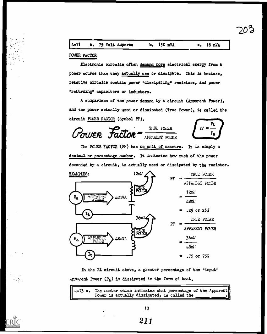
-20
Loll a. 75 Volt Amperes b. 150 mMA c. 18 mVA I
POWER FACTOR
Electronic circuits often demand more electrical energy from a
power eourcs than they actually use or dissipate. This is because,
reactive circuits contain power *dissipating* resistors, and power
*returning* capacitors or inductors.
A comparison of the power demand by a circuit (Apparent Power),
and the power actually used or dissipated (True Power), is called the
circuit POWER FACTOR (Symbol PF).
PAR faCTOR=TRUL F0a4R
APPARENT PAR
The PLUM FACTOR (PF) hae no unit of measure. It is simply a
decimal or percentage number. It indicates how much of the power
demanded by a circuit, is actually used or dissipated by the resistor.
PP
PF
TRUt PMER
APPAZENT FO4ER
12nU
48WV
sm .25
TRUE
or
PO
25%
WER
APPARENT POWER
36ei
48m11
= .75 or 75
In the RL circuit above, a greater percentage of the *input*
itppa:ent Power (Pa) is dissipated in the form of heat.
.4-43 a. The number which indicates what percentage of the ApparentPower is actually dissipated, is called the ..1111,
13
211

A-12a. 100W
b. 36 mW
c. 3S mW
d. Watt
e. True...in the form of heat.
OPERATING CHARACTERISTIC
Alternating current circuits'are spoken of as "operating" or
"acting": RESISTIVELY, CAPACITIVELY, or INDUCTIVELY. It depends upon
the type of circuit, and the components used.
This CIRCUIT, is OPERATING....
0-AAA,--frrmo
Purely resistive or resistively
Purely capacitive
Capacitively
Purely inductive
Inductively
In the case of Series RCL Circuits, the oppositions of the
capacitor and inductor determine how the circuit will operate.
This,CIRCUIT is OPERATING....
12k11. 16kst.
C".AAAO1(...frframm° Inductively
Capacitively
Resistively
16k4.6 12kru
C°mnmAIVN#1 ifIrtirtA-mm°
CPI\ONAI14ktl. 14 Al.
following circuits OPERATING or ACTING?
(c) 314.42 IhrtYrOk43.
(d) 61c.(n7I.V2(N..L4licru
(e)m-Ps/W---14firrnm71k11* 9k.n. 10k1t.
14
212
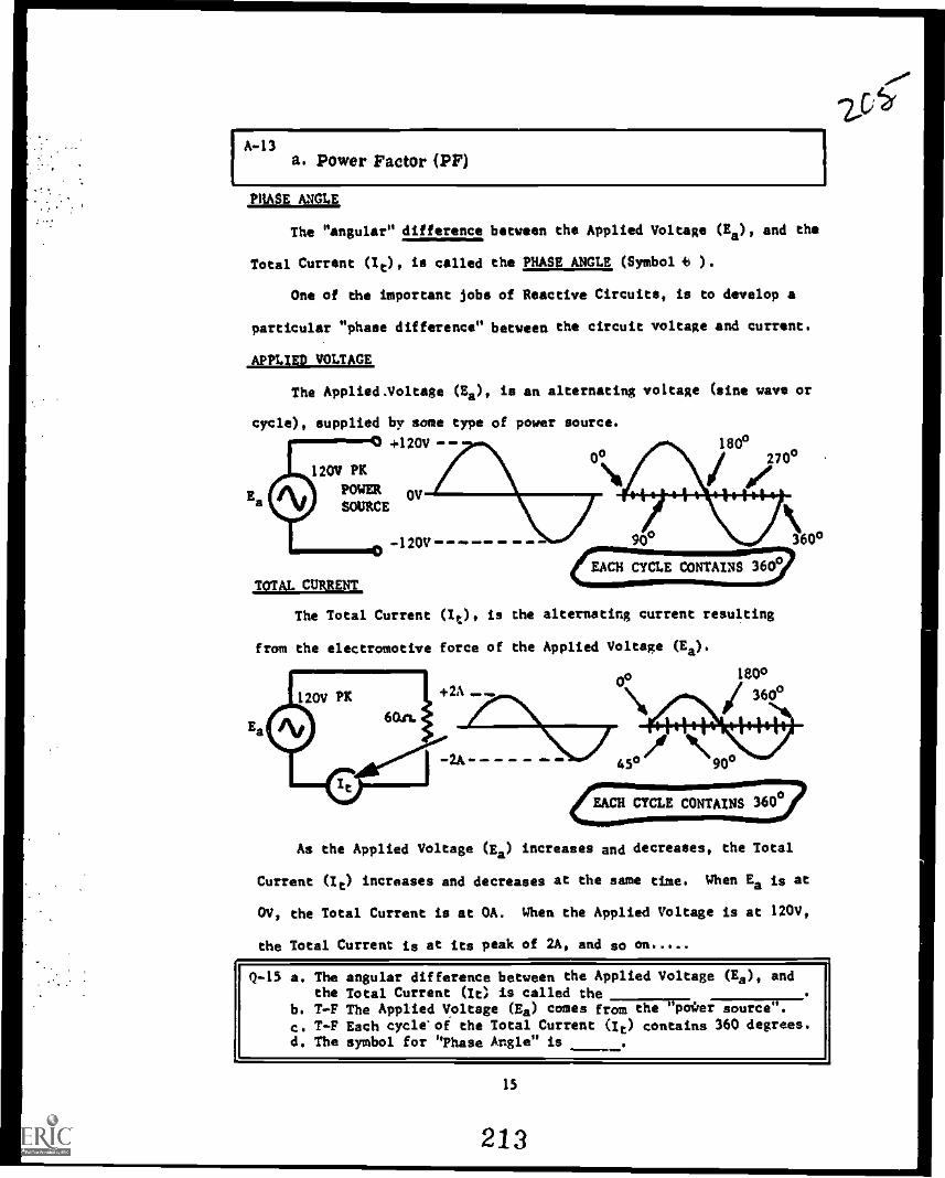
A-13a. Power Factor (PF)
,PHASE ANGLE,
The "angular" difference between the Applied Voltage (Ea), and the
Total Current (It), is called the PHASE ANGLE, (Symbol 8 ).
One of the important jobs of Reactive Circuits, is to develop a
particular "phase difference" between the circuit voltage and current.
APPLIED VOLTAGE
The Applied. Voltage (Ea), is an alternating voltage (sine wave or
cycle), supplied by some type of power source.
+120V 180°0° 270°
120V PK
POWER OVE
TOTAL CURRENT
The Total Current (10, is the alternating current resulting
from the electromotive force of the Applied Voltage (Ea).
o,14
360°
1800
45° "90°
CFlCIICYCLE CONTAINS 360°
As the Applied Voltage (Ea) increases and decreases, the Total
Current (It) increases and decreases at the same time. When Ea is at
OV, the Total Current is at OA. When the Applied Voltage is at 120V,
the Total Current is at its peak of 2A, and so on
Q-15 a. The angular difference between the Applied Voltage (Ea), andthe Total Current (It) is called the
b. T-F The Applied Voltage (Es) comes fr;171-gr"Fater source".
c. T-F Each cycle'of the Total Current (It) contains 360 degrees.d. The symbol for "Phase Angle" is _..
15
213

A-14
a. Capacitively
b. inductively
c, Inductively (XL larger than XC)d. Capacitively (XC larger than XL)e. inductively (XL larger than XC)f, Resistively (XC and XL equal)
PHASE ANGLE (cont)
The number of degrees difference between the Applied Voltage (Ea),
and the Total Current (it), depends upon the type of circuit.
PHASEANGLE
PURELY RESISTIVE
0/W1PiiAAN-sO A 0°
PURELY CAPACITIVE
CAPACITIVE
A 90°
42°
in a "capacitive" circuit,
The exact angle between voltage
of the resistor and capacitor.
%%Its,.current LEADS,yoltage.
and
PHASEANGLE %r
PURELY RESISTIVE0-0SAM-E-010W--0 0°
PURELY INDUCTIVE
0-1YYY1---rrrn-4 e-. 90°
INDUCTIVE
0-91ArtYrn--0 m. 450
0/11%current, depends upon the opposition
0in an "inductive" circuit, current,LAGS,hvoltage.
e I
The exact angle between voltage and current, depends upon the opposition
of the resistor and inductor.
Q-16 a, T-F In a "resistive" circuit,.the voltage and current are"in phase".
b. T-F In "capacitive" circuits, current "loads" voltage.c. I -F In "inductive" circuits, voltage "leads" current.
16
214
zotp

201A-15
e. Phase Angla....syMbol (49)
b. Trus....it is e "sine wave" voltage, supplied from sometype of power source such as a generator.
c. Trued. (0)..:actually, it is the Greek letter "theta".
PHASE ANGLE {cont)
The PHASE ANGLE (0 ), in a Series RCL circuit, depends upon how
the circuit is "operating". The opposition of the capacitor and induc-
tor determines how the circuit will "operate".
OPERATING RESISTIVELY
PHASE e00AMI Vfn-0 0°
OPERATING CAPACITIVELY
°-4A14-1 PrriP4 * 63°
6k.m. 4k".
OPERATING INDUCTIVELY
ci...Am11nrk-031C,e6
279
In a "capacitive" circuit, current LEADS voltage.
In an "inductive" circuit, current LAGS voltage. In an RCL circuit,
when the opposition of the capacitor and inductor is the same, the
circuit is operating "resistively, and the current is IN PHASE with
the voltage.
The exact number of degrees in the PHASE ANGLE,( 9 ), is deter-
mined by the oppositions of the various components.
Q-17 How will the following circuits "operate"?
(a) (b) (c)
1)-Wir`l Errr Imm° (--A6A"mrrn-4) 41"IrnA HAAP-133 kn. 4k..n. 5k 71cri. 13c.A. aka% 3 kr' 1 kn, 6k"
Will the Total Current "lead" or "lag" or be "in phase" with theApplied Voltage, in the following circuits.
(d) (e) (f)
e-'-'1 Vret-C) CH (-4414"-rfir sIrrtli (-"9-46MI 8k.A. 954% 5k.o. 21c41. *A. 12k0611t..A. 251141.
17
215

A.16 a. True....voltage and current ',rise and fall' together.b. True....it could also be said that voltage "lags', current.o. True....saying the voltage "leads" current, is the same as
saying current "lags" voltage.
PHASE M:a (wilt)
The PHASE ANGLE (0), for any reactive circuit, can be determined
thru the use of a Trigonometry Table. (The Electronics Handbook KEP-110
has such a table.) The only columns of interest now, are the Ncosineo
(cos) column, and the "degree" (deg) column.
To obtain some practice ueing these two columns, follow along in
the "trig" table with each of these examples:
At 45°, the table now
COSINE NUMBER(cosine column)
.9994
.9986
.9962
PHASE ANGLE(degree column)
2.0°3.0°s. °
. 9900
.9833
. 9673
8.1c10.5
14.2°
.9164
.87550829
23.28.9'34.0°
.7760
.719
.7071
39.144.0P45,0°
"folds back upon itself ", and is read backwards!
USE THE HEADINGS AT
THE BOTrOM CF THE
PAZ, AND READ UP
THE COMM.
.7009
.6997
.6947
45.5°45.6°46.0°
.6934 46.1°
.6691 48.00
.6521 69.3°
.6225 51.5
.5934 53.6°
.5314 57.9°
.489 60.7"
.36040 68.9!
.2351 76.4°
.1478 81.5
.0505 87.1°
Q-18 Look -up the Phase Angle (0), for each "cosine number" shown.
a.
b.c.
.9969
.9198
.7157
d,s.
f.
.6807
.3518
.1736
g. .6704h. .966i. .4772
18
216

A-17 a. Capacitively (XC larger) d. Current will "lag" (Inductivelyb. Inductively (XL larger) e. Current "in phase" (Resistive])'c. Inductively (XL larger) Z. Current will "lead" (Capacitive
PHASE ANGLE ((tont)
4)-JVVr-571---45
The PHASE ANGLE ( 0 ), is determined by use of a Trigonometry
Table. Several equations may be used to calculate the "cosine number",
which is then Used to look-up the Phase Angle ( 0).
R (Resistance)cosine =
Z (Impedance)
EXAMAIES:
Rcos =--
zk
131e
cos = .3846
0= 67.4°
ERCOO
Ea
18V
32V
cos = .5625
4s, 55.8°
Use whichever equa.ion is the easiest & most convenient at the time.
19
217
ti

A48a. 4.50b. 23.1°c. 44.3°
d. 47.1°e. 69.4°f. 80.0°
8. 47.9°h. 14.9°i. 61.3°
EQUATION SUMMARY
/Pt
Pa
Z 17+7Cc2
SERIES RC
Ea
t
ER It a
Ec It xcEa . Et271E72
- (It2 14 .(=ft:). (ER It
(Ea It) (/t 2 z) .. .Z
Encosine = jil or
a
0 = Look-up "cos" is Trig Table......."`(....I.
SERIES RCL( ryrn,
z . z2 + orn-zo2 z . z2 + oM- zo2
EaER It EC It lc XI. It XL
Ea ER2 {EC EL)2
Pt (It2 ft) a (Ei-t2) (ER It)
it ERcosine = or
a
Eit2 Ec)2
Ea
Pa (la It . (t 2 Z)
0 = Look-up "cos" is Trig Table
20
218
210

A-19 a. cosine = .3800 0 43 88.0° b. cos g .0500 0 m 18.2°
REACTIVE CIRCUIT PROBLEMS
Determine the type of circuit, select the proper group of equations
from the previous EQUATION SUMMARY, and solve the following Series React-
ive Circuit problems. Answers listed under A-20
21
219
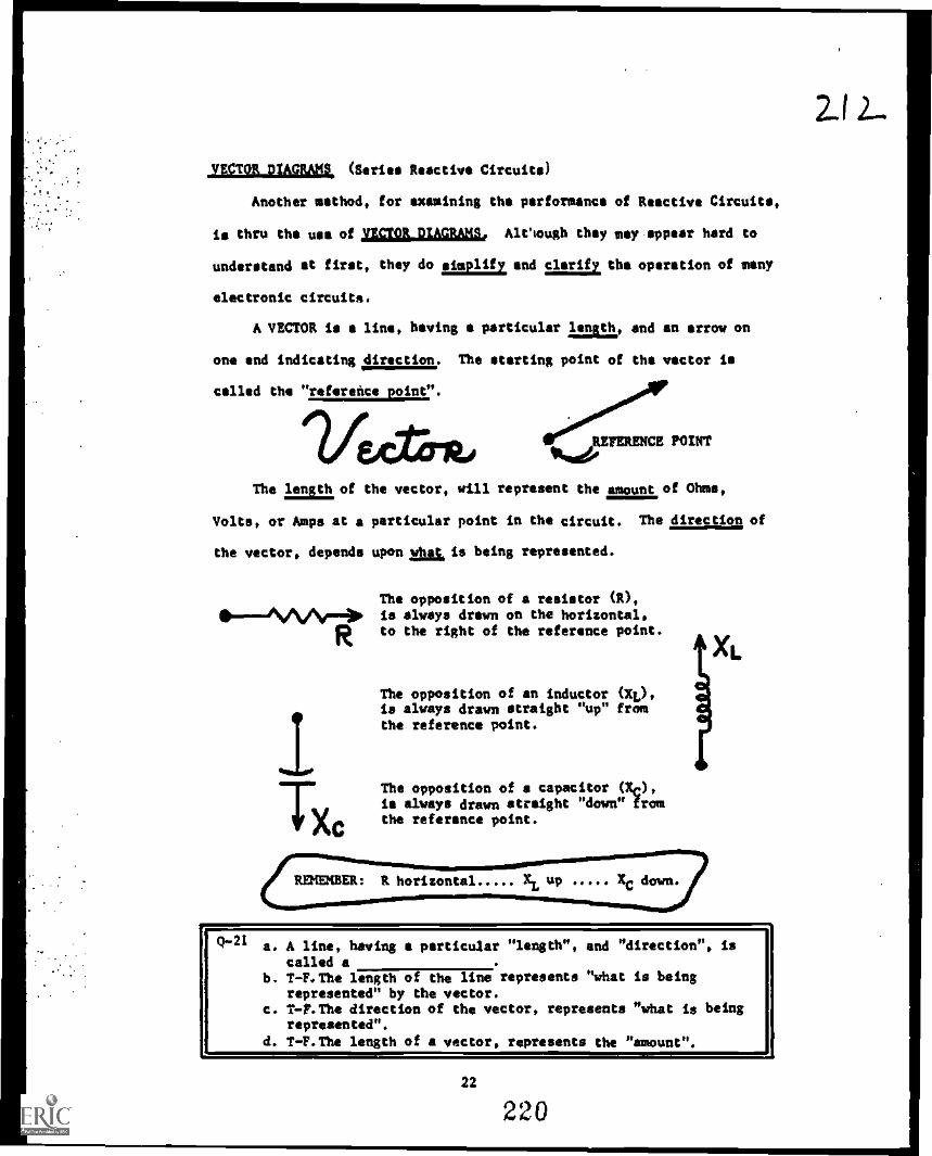
VECTOR DIAGRAMS (Series Reactive Circuits)
Another method, for examining the performance of Reactive Circuits,
is thru the use of VECTOR DIAGRAMS. AlCsough they may-appear hard to
understand at first, they do eimplify and clarify the operation of many
electronic circuits.
A VECTOR is a line, having a particular nalo and an arrow on
one end indicating direction. The starting point of the vector is
called the "reference point".
...;00°..4AIP
,REFERENCE POINT
The lmatof the vector, will represent the amount of Ohms,
Volts, or Amps at a particular point in the circuit. The direction of
the vector, depends upon what is being represented.
The opposition of a resistor (R),110----""A÷ is always drawn on the horizontal,
Rto the right of the reference point.
Tx,
The opposition of an inductor (XL),is always drawn straight "up" fromthe reference point.
The opposition of a capacitor (10,is always drawn straight "down" fromthe reference point.
REMEMBER: R horizontal
XL
Q-21 a. A line, having a particular "length", and "direction", iscalled a
b. T-F.The length of the line represents "what is beingrepresented" by the vector.
c. T-?.The direction of the vector, represents "what is beingrepresented".
d. T-F. The length of a vector, represents the "amount".
22
220
212-

A20 25 b. S 30k7
d. It 2mA
g. pa 200VA
3. PT .1529
a. 11g 112V
h. Pt 96MW
k. la 40V
,C4 It 2mA
f. lc 26V
I. PT .8823
1. 0- 53.1°
,VECTOR DIAGRAM8 (cont)
A vector diagram can be used to represent the oppositions, in
a Series Reactive Circuit. These circuits, and their vector diagrams,
are shown below. Remember: R horizontal.... XL up Xc down
SERIES RL
SERIES RC
SERIES RCL
XL
R
Q-22 match the following circuits with their proper vector diagram.
0.A.w...1 b
c
emlI
.111I
f
23
221
213

A-21 a. vectorb. False the length of a vector, represents the amount.c. True opposition of a resistor,(horizontal)...opposition of
a capacitor (straight down)...opposition of an inductor (up).d. True...the greater the opposition, the longer the vector.
,VECTOR DIAGRAMS, (coot)
The type of circuit, RC RL or RCL, can be determined by simply
drawing the ,vector diagram, instead of the actual circuit diagram.
The direction of the vector represents the of opposition. Recall
also...the physical lasshof the vector is "how much" opposition.
'INCREASING RESISTANCE CHANCES THE VECTOR DIAGRAM /
XI XI XL
1-0R L-10R
INCREASING INDUCTIVEREACTANCE CHANCESTHE VECTOR DIAGRAM
Xc
x.
t_.R R R
R
XeXc
(:DECREASING CAPACITIVE REACTANCE atc):0)CHANGES THE VECTOR DIAGRAM
(1-23 'latch circuits with vectors.
3Xc
F itP rit6
WXC
24
222
214

A22a . 2 b 0 3 c I
VECTOR DIAGRAMS (coat)
Series RC!. circuits, contain all three vectors: R, XC, and XL.
Remember, the direction of a vector represents the sym of opposition.
The length of the vector is determined by the amount of opposition.
"INCREASING RESISTANCE (E) CHANGES THE VECTOR,
Xi
x.
f
INCREASING INDUCTIVE REACTANCE (XL)CHANGES THE VECTORj
)1L16
R
)(C
R
XL XL
X6
&1---31°FR DECREASING CAPACITIVEREACTANCE (XC) CHANGES THE VECTOR
Q-24 Match circuits with vectors.
6.4-R0.2
4.
4
1 R
tr tryCc
*x
3 R
VAg
25
223

A-23a 0 3 b 0 2 c 4 d 0 6
IMPEDANCE VECTOR DIAGRAM
The total opposition (Impedance) of a Reactive Circuit, is also
represented by a vector. The IMPEDANCE (Z) vector is obtained thru
"vector addition".INDUCTIVE REACTANCE
RESISTANCE
VECTOR
The lennth of the IMPEDANCE (Z) vector, represents the areunt
of total opposition in the circuit. Notice how the total opposition
(length of Z vector) increases. with an increase in resistance (R).
Q-25 a. The "Impedance vector" is obtained thrub. Increasing the opposition of the resistance, causes the
total opposition (Impedance Z) to (inc or dec).c. Increasing the opposition of an inductor-74.), would cause
the total opposition (Impedance Z) to (inc or dee).NOTE: Look at the angle between R and Z. It may be important
26
224
2/40

2
IMPEDANCE VECTOR DIAGRAMS (cont)
The total opposition (Impedance) of nn RC Reactive Circuit, is
also represented by a vector. The IMPEDANCE (Z) vector is obtained
thru "vector addition".
VECTOR ADDITION
Parallel "dotted" lines
VECTOR SUM
The Impedance (Z) vector
REFERENCE POINT
144P
"r0APRESISTANCE
R
4...xv CAPACITIVE REACTANCE
/1-1
4114,444P
brit fIrT.N"
The length of the TIPEDANCE (7.) vector, represents the Amount
of total opposition In the circuit. %otice how the total onposition
(lenIth of Z vector) increases, with an increase of Caoacitive React-
ance (XC).
zR
1
1
i
1 v
0 1p It1
Xe 16e
I
1xtHOW A CHANGE OFCAPACITIVE REACTANCE (Xc)AFFECTS THE LENGTH OF THE IMPEDANCE VECT Z
'1-26 a. The Impedance vector is obtained thrub. The Impedance vector is called the sum.
c. T-F The "starting point" for vector diagrams is called theReference Point.
d. What would increasing the length of the "resistance R" vectordo to the total opposition (length of the Z vector)
e. T-F Frequency affects X. (inc-dec)
NOTE: There's that angle again....the one between R and Z ? ? ? ?
4
27
225
211

A-25
NOTE:
a. Vector Additionb. Increase....if the R vector is longer, the Zc. Increass..,.if the XL vector is drawn longer
the resulting Z vector will also be longer.Wonder what angle that is? Could it be the
vector is also.
(more opposition),
=8===BOIM.
IMPEDANCE VECTOR DIAGRAMS (cont)
The total opposition (Impedance) of an RCL circuit, is also
represented by a vector. The IMPEDANCE (Z) vector is obtained thru
"vector addition", but there is one step to be accomplished first.
THE DIFFERENCE VECTOR
In RCL circuits, all three, vectors (R, XC and XL) are present.
The XC and XL vectors are in opposite directions,
C"'HE CIRCUIT
tek".
3k 1L
Sk.n.
XL 5
'Cc = 3
Because XC and XL are in opposite directions, they must be
subtracted, and a "difference vector" obtained. (XL XC) 2
The "difference vector" is then added toXIvEFFECTROERNCy
the "resistance vector", and the "vector sum"
obtained. (XL - XC ir 014Z
I Lle$19t*e R/ VECTOR ADDITION
This then, is the complete vector
diagram, for an RCL circuit, COMPLETE VECTOR DIAGRAM
operating INDUCTIVELY. (XL greater than XC)
Q-27 a. In Series RCL circuits, thedetermined "first".
b. The "impedance" vector is obtained thru
c. Increasing the resistance (R vector) would Impedance.
NOTE: There's that angle again, between R and Z! inc -7Tdecit
vector must be
28
226
2/

A-26 a. vector additionb. vectorc. Trued. Increase....increasing either opposition, increases the total.e. True frequency increases, XC decreases 1
)(C inNOTE' Which angle? The one between R and Z! 4 21rftc
IMPEDANCE VECTOR DIAGRAMS (cont)
In an RCL circuit operating CAPACITIVELY (XC larger than XL), the
vector representing total opposition (Impedance) would be developed as
follows:
IXL 2 /DIFFERENCE VECTOR/
5c.n.
2k.n.
4 Ir 1,4
1
1
444, 1
i
4k n. R
Z
it.Xc 5
(XC -XL)
n (XC -XL)
This is the completed vector dinexam for(XC larger than XL)
an RCL Circuit, operating CAPACITIVELY.
XC
Q -23 Match the circuits with the proper IMPEDANCE VECTOR DIAGRAM.
O
6.n.
4/6
2.0.
It 8k.".
XC 2k.gra I 13
XL 5k.ei _ _ _
211
29
227
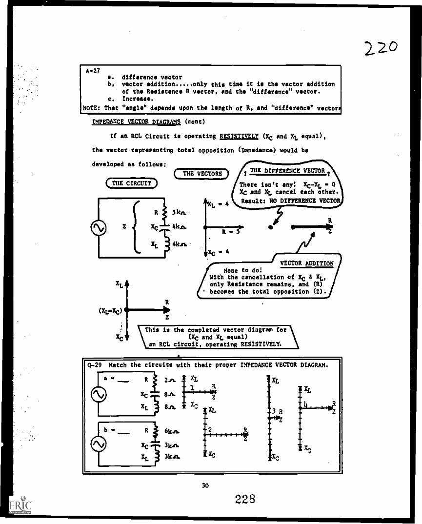
C THE VECTORS.)
A-27a. difference vectorb, vector addition only this time it is the vector addition
of the Resistance R vector, and the "difference" vector.c. Increase.
NOTE: That "engle" depends upon the length of R, and "difference" vectors
IMPEDANCE VECTOR DIAGRAMS (cont)
If an RCL Circuit is operating fESISTIVELI (XC and XL equal),
the vector representing total opposition (Impedance) would be
developed as follows:
( THE CIRCUIT
(XL -XC)z
L
7THE DIFFERENCE VECTOR
There isn't any XC -XL 0XC and XL cancel each other.
Result: NO DIFFERENCE VECTOR
XC4
None to dotWith the cancellation of XC & XL,only Resistance remains, and (R)becomes the total opposition (Z).
VECTOR ADDITION
This is the completed vector diagram for(XC and XL equal)
an RCL circuit, operating RESISTIVELY.
Match the circuits with their proper IMPEDANCE VECTOR DIAGRAM.
30
228
2. 2.0
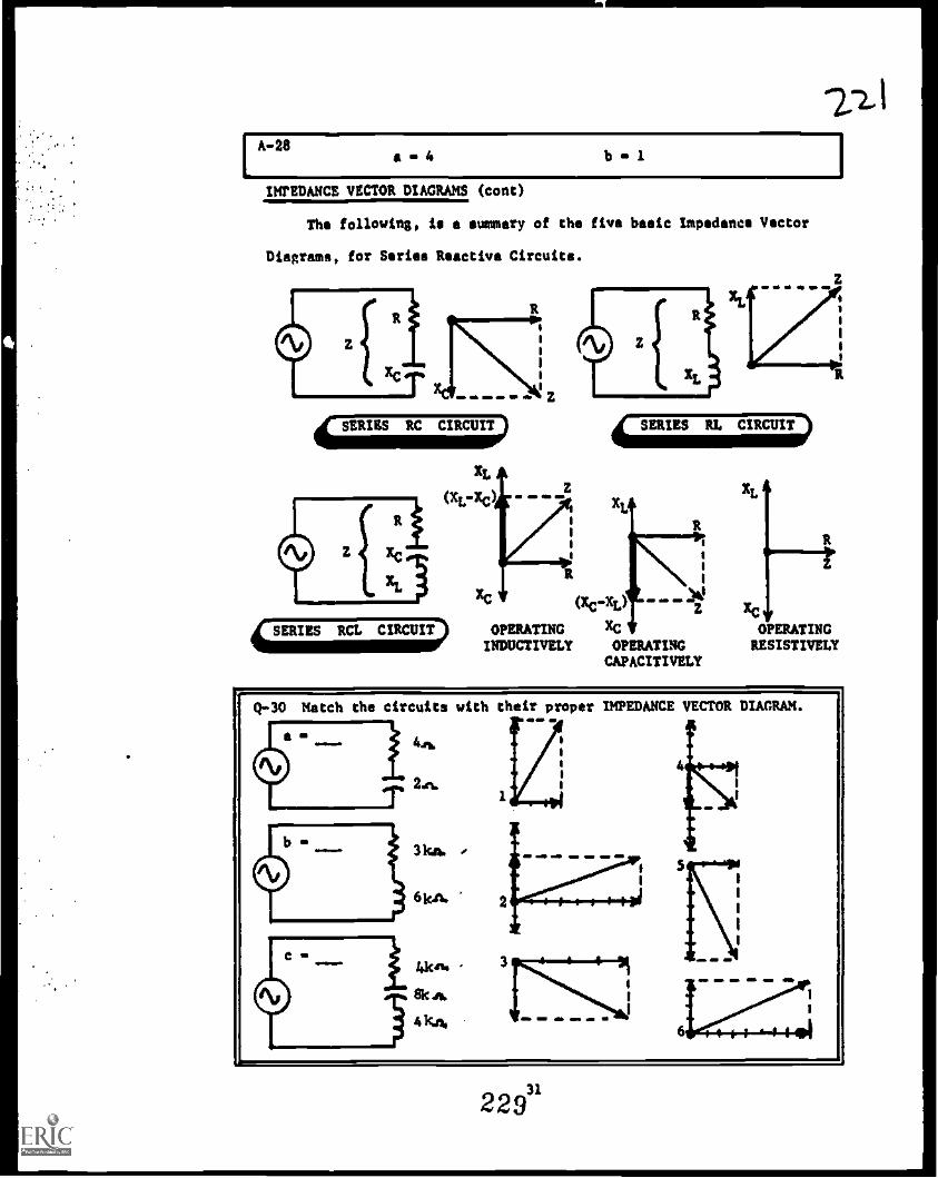
A-28a 4 b 1
AL
IMPEDANCE VECTOR DIAGRAMS (cont)
The following, is a summary of the five basic impedance Vector
Diagrams, for Series Reactive Circuits.
XL
(XL-Xc) Mr As gm.
a
I
xc oteco -ZI
OPERATING XCINDUCTIVELY OPERATING
CAPACITIVELY
xC
OPERATINGRESISTIVELY
Q-30 Match the circuits with their proper IMPEDANCE VECTOR DIAGRAM.
22?

a a 3 b -1
USING IMPEDANCE VECTORS
Impedance Vector Diagrams have several uses which will now be
discuseed.
It is NOT necessary to draw the actual schematicdiagram of the circuit. The Impedance Vector Dia-gram tells what type of circuit it is, and how itis operating.
It is easy to see, how changes in the amount ofResistance (R) or Reactance (Xc and XL), affectthe amount of Impedance (Z)....the length of theImpedance (2) vector.
HOW INCREASING INDUCTIVEREACTANCE AFFECTSIMPEDANCE
N.
R (inc)
X
BIZ
PPR
XL
XCT X XC
NOW INCREASING RESISTANCE AFFECTS IMPEDANCE
Z
R
N. w go M. =IP
Q-31 a. T-F Impedance vector diagrams can be drawn, instead of theactual schematic, to see haw a circuit is "operating".
b. TF It is easy to see the changes which occur in a circuit,when the impedance vectors are used, instead of equations.
NOTE: Soon that "angle" between R and Z, is coming up!
32
230
2Z2_.

A-30 a 3 b 0 1 c 4
USIN0 IMPEDANCE VECTORS, (cant)
If the individual Resistance and Reactancevectors are drawn "to scale", the amount of
THIRD Impedance (Z) can be measured directly fromthe drawing. This eliminates the need formathematical calculations for Impedance IP.
9kei.
12k"
XL 12pr. ... ORION
I
R 9
a 1R + XL
\17 47U41
\I 81
Z 15kso-
1111111711Voltage (En) and the Total Current (It). will
be the adros the angle between Resistance (R)
The PIIASE ANGLE OP) is present in the Impedance
vector diagram. The angle between the Applied
and Impedance (Z) vectors.
Angles chosen as EXAMPLES only:
Q-32 a. T-F The Impedance (a), can be measured directly from an accurately drawn Impedance Vector Diagram.
b. T-P The Phase Angle (71), can be measured directly from anaccurately drawn Impedance Vector Diagram.
c. T-F The angle between R and Z, has the same number of degrees
as the Phase Angle 00.
33
231
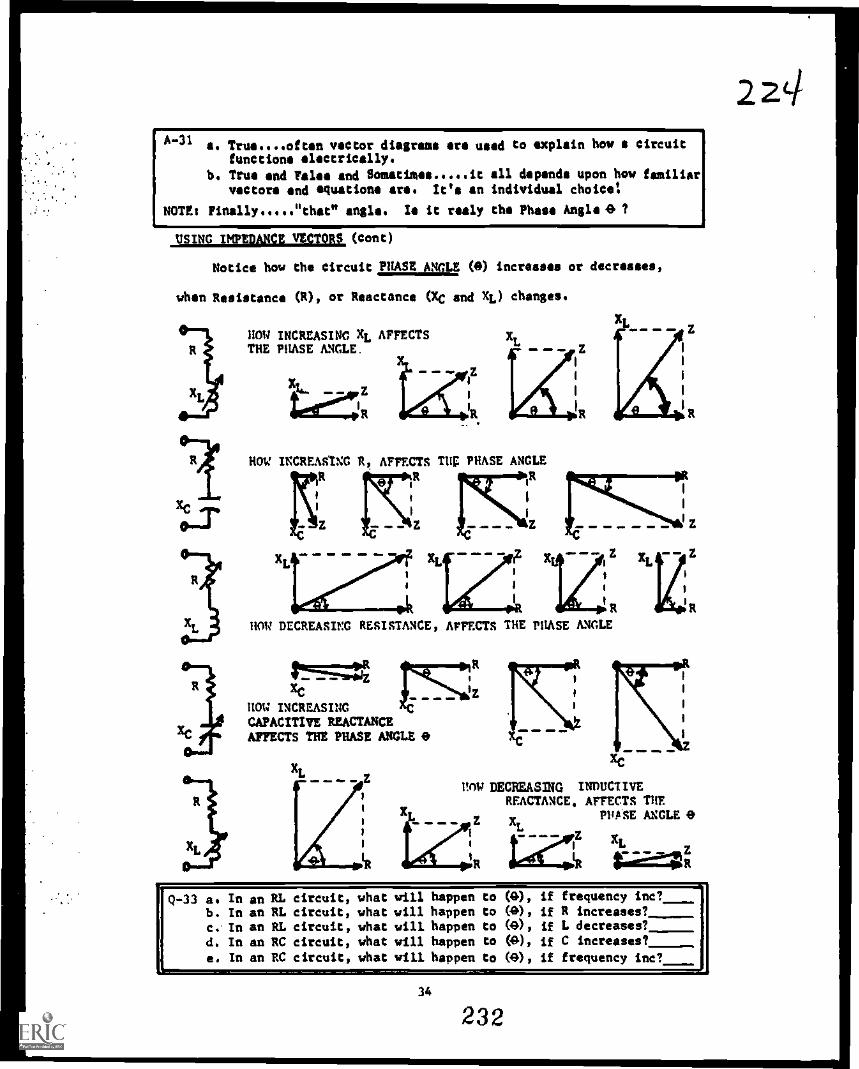
A-31 a. /rm....often vector diagrams are used to explain bow u circuitfunctions electrically.
b. True and False and Somatimes it all depends upon bow familiar
vectors and equations are. It's an individual choice!
MEI Finally "that" angle. Is it realy the Phase Angle0 ?
USING IMPEDANCE VECTORS (Cont)
Notice how the circuit PHASE ANGLE (D) increases or decreases,
when Resistance (R), or Reactance (XC and XL) changes.
HOW INCREASING XL AFFECTSTHE PHASE ANGLE.
HOW INCREASUG R AFFECTS THE PHASE ANGLE
HOW DECREASING RESISTANCE, AFFECTS THE PHASE ANGLE
HOW INCREASINGCAPACITIVE REACTANCEAFFECTS THE PHASE ANGLE 0
.1=1.4
R
Oz
HOW DEGREASING INDUCTIVEREACTANCE, AFFECTS THE
E XLPHASE ANGLE 0
iz xi.E
leLA -t.....i
4t
Q-33 a. In an RL circuit, what will happen to (40, if frequency inc?b. In an RL circuit, what will happen to (1.0), if R increases?c. In an RL circuit, what will happen to 00, if L decreases?d. In an RC circuit, what will happen to (A), if C increases?e. In an RC circuit, what will happen to 00, if frequency inc?
34
232

A-32 a. True....the more accurate the drawing, the more accurate will bethe Impedance measurement.
b. True....although it is NOT the Phase Angle, it has the samenumber of degree*, and is often marked as M.
c. True....see answer (b) above.
USING IMPEDANCE VECTORS (cont)
RCL circuits, containing all three vectors (R, XC, end XL), are
somewhat more difficult. Observe the shift in the "EASE ANGLE,(e)
when the following changes are made.
XL
XC *
xts
xcHOW DECREASING XC, CHANCES THE PHASE ANCLE0
HOW INCREASING INDUCTIVE REACTANCE,AFFECTS THE PHASEANGLE 0
41 0°X
Z ktini1S,
XC
XL
HOW INCREASING RESISTANCE AFFECTS THE PEASE ANGLE .0
XL XL
R
Q-34 a. In an RCL Circuit, operating inductively, what will happen to(40) if the frequency is increased?
b. In an RCL Circuit, operating inductively, what will happen to(0) if the Resistance (R) is decreased?
c. In an RCL Circuit, operating inductively, what will happen to(e) if the Inductance (L) is increased?
d. In an RCL Circuit, operating CAPACITIVELY, what will happen to(0) if the frequency is increased?
e. In an RCL Circuit, operating capairEMT, what will happen to
(0) if the Resistance (R/_is decreased?
35
233
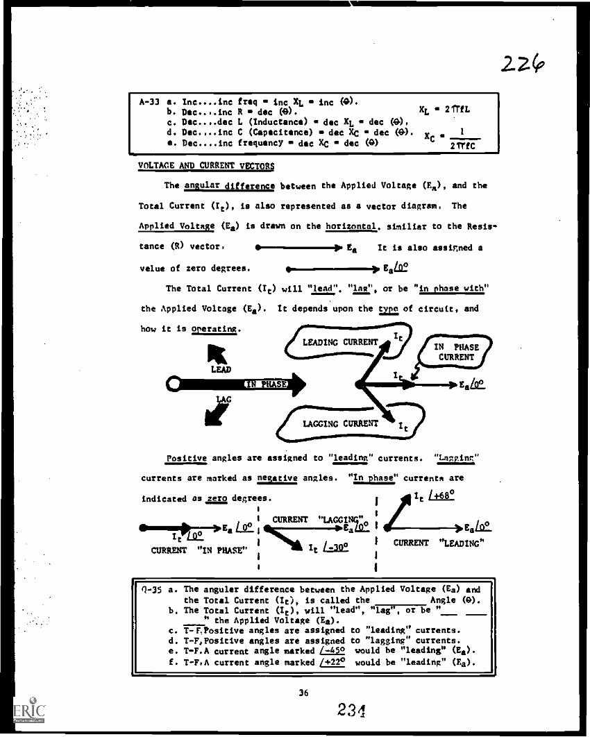
A-33 a. Ine....ine fraq inc XL inc M.b. Dae..,.ine R dec (0). XL 21TfL
c. Dae..,.dae L (Inductance) dec XL dec (0),d. Dee.,..inz C (Capacitance) dec XC dec (A). x
1a. Dee....ine frequency dec XC dec (Q) C 2111C
VOLTAGE AND CURRENT VECTORS
The angular difference between the Applied Voltage (Ea), and the
Total Current (It), is also represented as a vector diagram, The
Applied Voltage (Ea) is drawn on the horizontal, similiar to the Resis-
tance (R) vector, Ea It is also assigned a
value of zero degrees. 111--111EaLteThe Total Current (It) will "lead", "laz", or be "in phase with"
the Applied Voltage (Ea). It depends upon the Expl of circuit, and
how it is operating.
LEAD
Positive angles are assigned to "leading" currents. lllIgl"
currents are marked as missive angles. "in phase" currents are
indicated as zero degrees.
1 CURRENT "LAGGING_
i It
1
el7107-10".0... Ea Li.; i Eats_ 1 EaLe.
i 477:21.0. 1 CURRENT "LEADING"CURRENT "IN PHASE"
1
1
),
Q -35 a. The angular difference between the Applied Voltage (Ea)
the Total Current (It), is called the Angle 01).b. The Total Current (It), will "lead", "Iii"7-1317174 "
" the Applied Voltage (Ea).c. T-F,Positive angles are assigned to "leading" currents.d. T-F,Positive angles are assigned to "lagging" currents.e. T-F.A current angle marked /-450, would be "leading" (Ea).
f. T-F,A current angle marked 1412° would be "leading" (Ea).
36
234
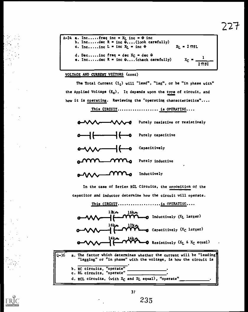
2z7
[
A-34 a. Inc freq inc XL inc A incb. Inc dec R inc 6....(look carefully)
C. Inc inc L inc XL inc 0
d. Dec inc freq m dec Xc dec Ae. Inc dec R inc0....(chock carefully)
xt. 2TrfL
VOLTAGE AND CURRENT VECTORS (cont)
The Total Current (It) will "lead". "lag", or be "in phase with"
the Applied Voltage (Ea). It depends upon the type of circuit, and
how it is operating. Reviewing the "operating characteristics".,..
This CIRCUIT is OPERATING....
4)-fSAArNA11,/-0 Purely resistive or resistively
(-13 Purely capacitive
.-NAAr 1E-0 Capacitively
Purely inductive
10-AAN--"Yr14 Inductively
In the case of Series RCL Circuits, the opposition of the
capacitor and inductor determine how the circuit will operate.
This CIRCUIT is OPERATING....
la" 16k,..
cpIVVV.Iharrun.c. Inductively (XL larger)
12 tA.
Capacitively (XC larger)
o_ivvisf_441cryVvit.4)Resistively (XL 6 Ec equal)
Q-36 a. The factor which determines whether the current will be "leading""lagging" or "in phase" with the voltage, is how the circuit is
b. RC circuits, "operate"c. RL circuits, "operate"
d. RCL circuits, (with Xc and XL equal), "operate"
37
235

I
A-35 a. Phase Angle (0)b. "in phase with"C. TVAd. Palse 6666 "lagging" currents have negative angles assigned.e. Pales....it would be "lagging" by 45 degrees.f. True
VOLTAGE AND CURRENT VECTORS, (cont)
' In "purely resistive" circuits, the Total Current (It) will be
"In phase" with the Applied Voltage (Es).
Ita
ell ell MIP 410
414.6
In "purely capacitive" circuits, the Total Current (It), will be
90e out of phase with the Applied Voltage (Es). The current will LEAD
In a Series RC circuit, operating "capacitivele, the Total Cur-
rent (/t) will LEAD the Applied Voltage (Ea), but NOT, by the full 90°.
It will lead by the PHASE ANGLE (D), for that particular circuit.
It
0 68°Eat
,Remember: The Resistance (R), and the Capacitive Reactance (X0),
determine the exact number of degrees in the PHASE ANGLE (3).
I Q-37
a. In "capacitive" circuits, current voltage.
b. T-P In an RC circuit, Ir "leads" EA by 90 firer. .._
38
236
zi

A-36a. operating or acting
b. capacitivelyc, inductivelyd. resistively (with XC and XL equal)
VOLTAGE AND CURRENT VECTORS,(coat)
In "purely resistive" circuits, the Total Current (It) will be
"In ease with the Applied Voltage (Ea).
00a
In "purely inductive" circuits, the Total Current (It), will be
90° out of phase with the Applied Voltage (Ea). The current will LAC
the voltage. Ea
Om 4w MI
LAG
It / -90°,
In a Series RL circuit, operating "inductively". the Total Cur-
rent (It) will LAG the Applied Voltage (Ea), but by the full 900.
It will lag by the PHASE ANGLE (9), for that particular circuit.
Ea 00
9 43°
It / ,
.Remembest The Resistance (R), and the Inductive Reactance (EL),
determine the exact number of degrees in the PRASE ANGLE (9).
Q-38 a. In an "inductive" circuit, current voltage.b. In an RL circuit, It "lags" Ea by 90 degrees. (T-F)
39
237
22-1

IA-37 so "leads"b. Falst..A.current leads voltage by the "phase angle"
VOLTAGE AND CURRENT VECTORS
In Series RCL Circuits operating "resistively", the Total Cur-
rent (It), will be "in phase" with the Applied Voltage (Ea).
In Series RCL Circuits operating "capacitively", the Total Cur-
rent (It), will LEAD the Applied Voltage (Ea). It will LEAD by the
PHASE ANGLE (9) for that particular circuit.
It Es
41,;68°
in Series RCL Circuits operating lnilactively", the Total Cur-
rent (It), will la the Applied Voltage (Ea). It willLby the
PHASE ANGLA (9) for that particular circuit.
The factors that determine the exact PEASE ANGLE, (0) for these
circuits are: Resistance (R), Capacitive Reactance (X,,) and Inductive
Reactance (XL).
li
(-1-'F a. T-F In a "capacitive" RCL circuit, current "leads" voltage.
b. T-F In an "inductive" RCL circuit, current "leads" voltage.
40
238
2 g)
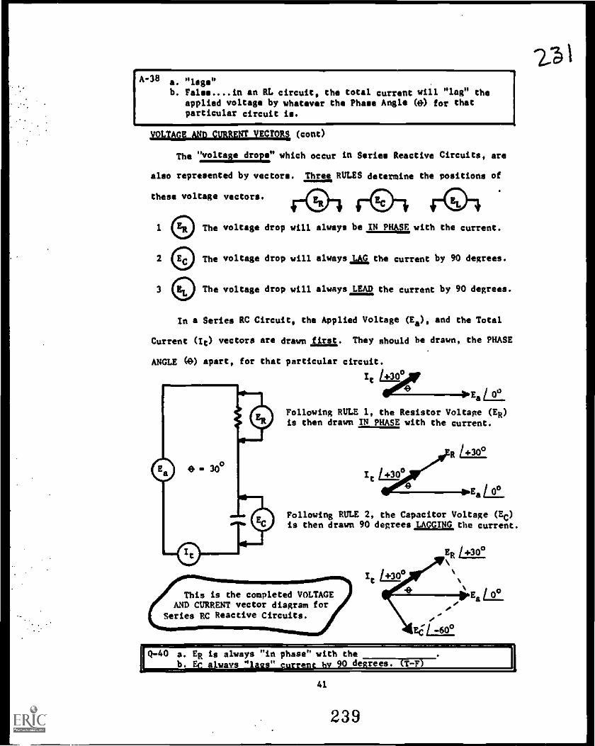
A-36 a. "lags"b. False.... in an RL circuit, the total currant will "lag" the
applied voltage by whatever the Phase Angle (e) for thatparticular circuit is.
szakupsjaufamma (cont)
The "voltage drops" which occur in Series Reactive Circuits, are
also represented by vectors. Three RULES determine the positions of
these voltage vectors.
The voltage drop will always be,tN PHASE with the current.
The voltage drop will always la the current by 90 degrees.
The voltage drop will always LEAD the current by 90 degrees.
In a Series RC Circuit, the Applied Voltage (Ea), and the Total
Current (It) vectors are drawn first. They should be drawn, the PHASE
ANGLE (0) apart, for that particular circuit.
It L±22°
EaLlt.
Following RULE 1, the Resistor Voltage (ER)is then drawn IN PHASE with the current.
to EaLt.Following RULE 2, the Capacitor Voltage (EC)is then drawn 90 degrees,LAGGING,the current.
This is the completed VOLTAGEAND CURRENT vector diagram for
Series RC Reactive Circuits.
41
239
II I

A-39a. Trueb. False....in "inductive" circuits, current "lags" voltage.
VOLTAGE AND CURRENT VECTORS (cont)
In a Series RL Circuit, the Applied Voltage (Ed, and the Total
Current (It) vectors are drawn first. They should be drawn, the PHASE
ANGLE (9) apart, for that particular circuit.
AEa L92.
It
Following RULE 1, the Resistor Voltage (ER)is then drawn ,IN MOE, with the current.
:183
It L14.
ER 1.3c).
Following RULE 3, the Inductor Voltage 1EL)is then drawn LEADIN0 the current by 90'.
/ +so°
itL
This is the completed VOLTAGEAND CURRENT vector diagram for
Series RL Reactive Circuits.
Q-41 Match the circuits with their proper VOLTAGE-CURRENT diagram.
1
EL
EL
Ea 4 It
Ea
EE
1mEa
42
210
232

I
ALWAA..40 a. current YS "in phase" with the current:b. True ALWAYS "lags" by 90 degrees:
VOLTAGE AND CURRENT VECTORS, (cant)
Concerning Series RCL Circuits, the first example will be for one
operating "capacitively", with its LEADING current.
t
Following RULE 1, the Resistor Voltage (ER)is then drawn IN PHASE with the current.
sots
Following RULE 2, the Capacitor Voltage (EC)is then drawn LAGGIJIG the current by 900.
Following RULE 3, the Inductor Voltage (EL)is then ¢raven LEADING the current by 900
ER
C
ER
Ea
a
Finally, as EC and EL are opposite (180°out of phase), a "difference" vector iscreated. and drawn in. (EC - EL)
This is the completed VOLTAGECURRENT vector diagram, for a
Series RCL Circuit, operatingCAPACITIVELY. (Leading current) (EC-EL)
Ea
Q-42 a. T-F In any RCL circuit, ER is "in phase" with the current.b. T-F In a "capacitive" RCL circuit, It "lags" Ea.c. T-F In a "capacitive" RCL circuit, EL "leads" Ea.d. T-F In a "capacitive" RCL circuit, EC "lags" Ea by 90 degrees.
e. T-F In a "capacitive" RCL circuit, EC "leads" ER by 900,
43
241

A-41 a in 4 b is 2
VOLTAGE AND CURRENT VECTORS (cont)
The VOLTAGE-CURRENT vector diagram for an RCL Circuit, operating
"inductively", is developed as follows. INDUCTIVE (Lagging current)
AEa
It
Following RULE 1, the Reeistor Voltage (ER)is then drawn IN PHASE with the current,
`4.4,,
Following RULE 2, the Capacitor Voltage (Ec)is then drawn LAGGING the current by 900.
441111111*PE*
8C11\41)Following RULE 3, the Inductor Voltage (EL) ERis then drawn LEADING the current by 90°.
Finally, as EL and EC are opposite (180°out of phase), a "difference" vector iscreated, and drawn in. (EL - EC)
EL
This is the completed VOLTAGECURRENT vector diagram, for a
Series RCL Circuit, operatingINDUCTIVELY. (Lagging current)
Ea
R
Q-43 a. T -F.In any "inductive" circuit, current "lags" voltage.b. T-F.In an "inductive" RCL circuit, ER "lags" Ea.c. T-F,In an "inductive" RCL circuit, EL "leads" Ea.d, T-F,In an "inductive" RCL circuit, EC "leads" Ea.e. T -F. In an "inductive" RCL circuit, EL "leads" Er by (D).
44
212
111111111
2 34-

A'42 a, True ER ie ALWAYS "in phase" with the current.b. False the current "leads" Ea by the Mom Angle (4).c. True by the Phalle Angle (a) + 90 degree,.d. "lags" OK....but NOT by 90 degree,.s. False Ec "lags" ER by 90 degrees.
VOLTAGE AND CURRENT VECTORS (cont)
The VOLTAGE-CURRENT vector diagram for an RCL Circuit, operating
"resistively". is developed as follows. RESISTIVE (Inphase,current)
4)
Cle:
Ea
Following RULE 2, the Capacitor Voltage (EC)is then drawn LACCINC the current by 90°.
01,4 /
EC
Following RULE 3, the Inductor Voltage (EL)is then drawn LEADING the current by 90°.
Because EC and EL are equal in amount.and opposite in phase, they cancel.NO "difference" vector is created,and there is NO vector addition toaccomplish.
EL
(EC -Et)
1111Ea
Since EC and EL cancelled each other, onlythe Resistor Voltage (ER) remains. Follow-ing RULE 1, the Resistor Voltage (ER) is thendrawn IN PHASE with the current, and equal tothe Applied Voltage (Ea).
This is the completed VOLTAGECURRENT vector dinnram, for a
Series RCL Circuit, operatingRESISTIVELY. (In-phase current)
EL
EC
o°
ER
O.La
Q -44 a. The Total Current (It) is "in phase" with the Applied Voltage
(Ea), in RCL circuits "operating"
b. T-F In RCL circuits Ec "leads" and Et "lags" the current.
45
243

A -43 a. Trueb. Trus by the Phase Angle 00.c. True by 90 degrees minus the Phase Angle (G).d. False it "lags" Ea by the Phase Angle (9) + 90 degrees.a, False it "leads" OX, but not by the Plums Angle OW
USING VOLTAGE VECTORS
Later, in Electronics training, voltage vectors will be used to
explain the operation of many complex circuits. At this time, they
will be used to show the expected results, when these voltages are
displayed on an Oscilloscope.
For example: If the ,PHASE ANGLE 00, for a Series RC Circuit,
is 30 degrees, the voltage-current vector is as follows.
It
The following Oscilloscope displays would be observed.
USING THESE TWO VOLTAGES THIS DISPLAY WILL BE SEEN
ER
30°IP Ea
II Ea
60'
IC
C
Q-45 a. T-F In an RC circuit, ER leads Es by the Phase Angle (9').
b. T-F In an RC circuit, EC and ER are 90 degrees out of phase.c. T-F In an RC circuit, EC and Ea are 90 degrees out of phase.
46
244
2VP

j
A44a, resistivelyb, False just the reverse ..... in all RCL circuits, EL "leads"
current, and EC "lags" current.
SING VOLTAGE VICTORS (cont)
If the PHASE ANGLE 01), for a Series RL Circuit, is 26 degrees,
the voltage - current vector diagram is es follows:
The following Oscilloscope displays would be observed.
USING THESE TWO VOLTAGES THIS DISPLAY WILL BE SEEN
EL 00,0"wvie.Et
\94.1 14.
4Z!!::64°
a
64'3..1 I..
EL Ea
[m.
(1-46 a. T-F In an RL circuit, ER and Ea are (9), out of phase.b. T-F In an RL circuit, EL and Ea are (9), out of phase.c. T-F In an RL circuit, EL "lags" ER by 90 degrees.d. T-F In an RL circuit, Ea "lags" EL.
47
245

A..45a. Trueb. Truec. Valee....they are 90 degrees sinus 00, out of phase.
USING VOLTAGE VECTORS (cont)
An RCL Circuit, with a PHASE ANGLE (0) of 20 degrees INDUCTIVE.
USING THESE TWO VOLTAGES.
(EL-EC)
THIS DISPLAY WILL BE SEEN
90
too"
EC
via
14--180°--01%. /, ".*4.,
48 246
235

A-46a. Trus....with ER lagging Eab. Pa lee...they are 90 degrees minus the Phase Angle* out of phase.a. Pa ise...EL leads ER by 90 degrees.d. True. ...they are 90° minus (0), out of phase.
VECTOR SUMMARY IMPEDANCE VECTOR MigAGE-CUIONT VECTO(
RL
RC
OPERATINGINDUCTIVELY
OPERATINGCAPACITIVELY
.xi. - *a a* ***
I
I
IIIIR
CL
OPERATING CAPACITIVELY
OPERATINGRESISTIVELY
INE
1 (EC-EL
EL
Ea
EC EC
EL
ER
XL
(XL-XC)
OPERATING INDUCTIVELY
XC
49
247
EC
EL
eEa
Ec
EL
(EL" EC
>R lir Ea
/R
EA'
Ea
SUMMARY
This study of Reactive Circuits is only a beginning, providingthe basic theory and calculations involved. Using this thorough"start", more advanced circuit theory can now be studied and under-stood. Technical reference centers provide many publications on theUSG and applications of "reactive" circuits.
Many of these publications have vector diagrams for detailedexplanation, and using the knowledge gained here, a more completeunderstanding can be obtained.
The use of Trigonometry in the solution of reactive circuits,is an accepted practice in most technical books, and the skills nowlearned should be put to use, studying advanced circuitry.
It has not been an "easy" subject. It was never intended to be.Combinations of resistors, capacitors, and inductors, form thecontrolling centers of all radio, television, radar, communications,and Space systems, The maintenance of this critical equipment, canonly be accomplished by qualified technicians, who understand thatit is the "inter-working" of simple components which results in thehigh standards of equipment performance required today.
Reactive Circuits in the middle of it ALL:
ATC laester 5-295 50
248
24ko

04111PARM MAN
fis' 241ATC GP 3A0113X020-X
Prepared by Kessler TTCKEP-012-22
Technical Training
ELECTRONIC PRINCIPLES (MODULAR SELF-PACED)
Module 22
PARALLEL RCL CIRCUITS
1 July 1974
7-Kessler Technical Training Center
Kessler Air Force Base, MississippiSupersedes KEP-GP-22, 1 November 1973, which will be used until stock isexhausted.
Designed For ATC Course Use
DO NOT USE ON THE 101
249

Basic and Applied Electronics DepartmentKees ler Air Force Base, Mississippi
Electronic Principles
PARALLEL RCL CIRCUITS
Module 22
ATC GP 3AQR3X020-XKE P -OP-22
1 July 1974
This Guidance Package is designed to guide you through this module of the Electronic Prin-ciples Course. It contains specific information, including references to other resources you maystudy, enabling you to satisfy the learning objectives.
CONTENTS
TITLE PAGE
Overview 1
List of Resources 2
Digest 3Adjunct Guide 6Module Self-Check 13
Supersedes KEP-GP-22, 1 November 1973, which will be used until stock is exhausted.
i 20
l

OVERVIEW
PARALLEL RCL CIRCUITS
1. SCOPE: This module expands on your knowledge of capacitors, coils, and resistors as theyapply to RCL circuits. You will compute voltage drop, currents, phase angle, impedance, andpower factor for parallel RCL circuits.
2. OBJECTIVES: Upon completion of this module you should be able to satisfy the followingobjectives.
a. Given a parallel RCL circuit diagram with component values, applied voltage, fre-quency, and formulas, solve for power factor, true power, and apparent power.
b. Given a parallel RCL circuit and vector diagrams, select the vector diagram repre-senting the relative amplitude and phase relationships of It, IR, IC, and IL.
c. Given a parallel RCL circuit diagram with component values, frequency, amplitudeof applied voltage, and formulas, solve for branch currents, approximate phase angle, totalcurrent, and total impedance.
d. Given a parallel RCL circuit diagram with component values, branch currents, andformulas, solve for applied voltage.
e. Given a parallel RCL circuit diagram with component values and formulas, solve fortotal impedance by assuming an applied voltage.
AT THIS POINT, YOU MAY TAKE THE MODULE SELF-CHECK.
IF YOU DECIDE NOT TO TAKE THE MODULE SELF-CHECK, TURN TO THE NEXT PAGE ANDPREVIEW THE LIST OF RESOURCES. DO NOT HESITATE TO CONSULT YOUR INSTRUCTORIF YOU HAVE ANY QUESTIONS.
2151

LIST OF RESOURCES
PARALLEL RCL CIRCUITS
lb satisfy the objectives of this module, you may choose, according to your training,experience, and preferences, say or all of the following:
READING MATERIALS
Digest
Adjunct Guide with Student Text
AUDIO-VISUALS
Television Lesson, Parallel RCL Circuits, TVK 30-263
SELECT ONE OF THE RESOURCES AND BEGIN YOUR STUDY OR TAKE THE MODULESELF-CHECK.
CONSULT YOUR INSTRUCTOR IF YOU REQUIRE ASSISTANCE.
2252
)
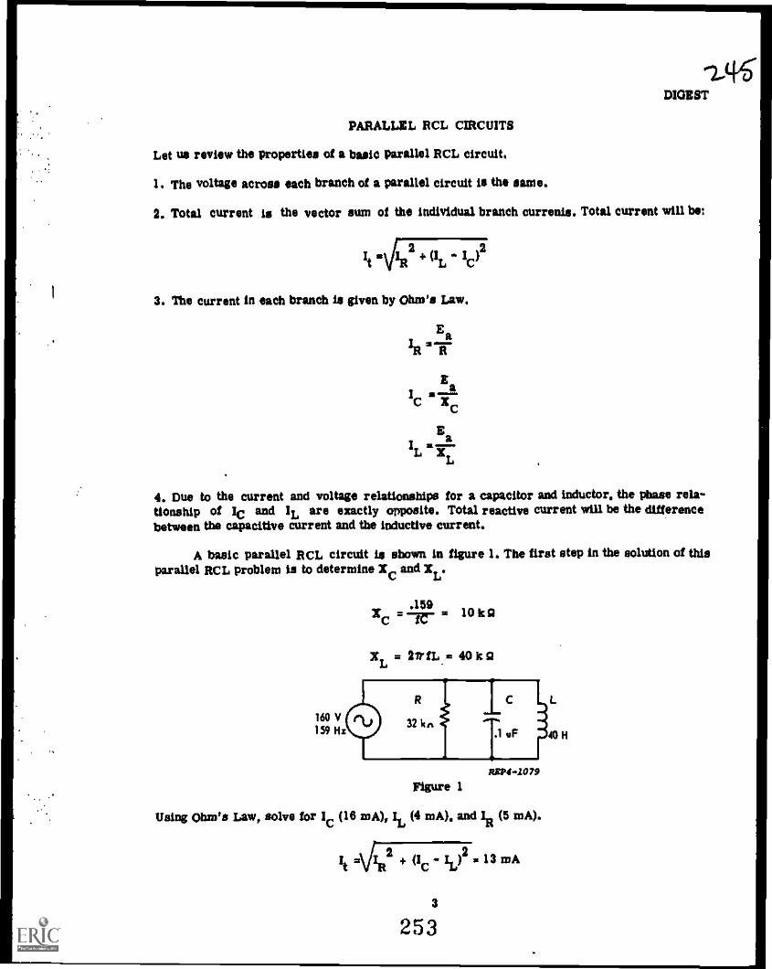
11.416DIGEST
PARALLEL RCL CIRCUITS
Let us review the properties of a basic parallel RCL circuit,
I. The voltage across each branch of a parallel circuit is the same.
2. Total current is the vector sum of the individual branch currents. Total current will be:
412
3. The current in each branch is given by Ohm's Law,
Ea
In'TaI
Cis''"""
XC
IL=a
4. Due to the current and voltage relationships for a capacitor and inductor, the phase rela-tionship of lc and IL are exactly opposite. Total reactive current will be the differencebetween the capacitive current and the inductive current.
A basic parallel RCL circuit is shown in figure 1. The first step in the solution of thisparallel RCL problem is to determine X
Cand
XL.
.159XC = = 10 ILO
XL = 2irfL = 40 ka
AXP4*1079
Figure 1
Using Ohm's Law, solve for lc (16 mA), it (4 mA), and In (5 mA).
It Ailit2 + (lc - Id2 = 13 mA
3
253

DIGEST
Using total current and the applied voltage, solve for total impedance.
zisi2.3k
41110 OMM .11111.
y IL 4m
A
Figure 2
It =13 mA
rnA
REPO -1080
Figure 2 shows the relationship of the current values. Angle 0 can be determined by using thecosine function.
IRCos a =: mA diqiu
It 13 mA
Referring to the trigonometric tables, find angle 0 to be 67.4%
We say the circuit is acting capacitively if -the capacitive current is larger than theinductive current. How the circuit acts is determined by which reactive component has thelarger current.
As with series RCL circuits, there is no real power dissipated by the capacitor or theinductor in a parallel RCL circuit. Real or true power (Pt) is the power dissipated by theresistor.
2ER
Pt IRER RI 2
R
4254
2A9

°It'llDIGEST
The unit of measurement of Pt is the watt. Apparent power (Ps) is the product of Ea and Itand is measured in volt amperes (VA).
ER22Pt a TBER 117r . 1 It
In this circuit, P is 2.08 V A and pt is 800 mW. Power factor (PF) is the ratio of true powerto apparent power.
Pt 800 mWPP
a8 :.3846
P 2.08 VA
Notice that the PF is the same as the Cos of the phase angle (A).
When the applied voltage is not given, you can solve for total impedance by using anassumed voltage. Use the assumed voltage and calculate the current through each branch.Combine the branch currents to determine total current. Use total current and the assumedvoltage to calculate total impedance. Regardless what voltage is assumed, the impedancewill be correct because impedance is the ratio of current to voltage.
r
YOU MAY STUDY ANOTHER RESOURCE OR TAKE THE MODULE SELF-CHECK.
S
255

ADJUNCT GUIDE
PARALLEL RCL CIRCUITS
INSTRUCTIONS:
Study the referenced materials as directed.
Return to this guide and answer the questions.
Check your answers against the answers at the top of the next even numbered page fol-lowing the questions.
If you experience any difficulty, contact your instructor.
Begin the program.
A. Turn to Student Text Volume III and read paragraphs 4-1 through 4-6. Return to this pageand answer the following questions.
I. Mark true (T) or filse (F) for each of the following statements pertaining to parallelcircuits.
00a. The voltage across all components is of exactly the same phase and amplitude.
b. The current is always the same through all branches.
11/611=Ile
c. The total current is the vector sum of the branch currents.
d. The voltage across a capacitor leads the current.
e. The current through a coil lags the voltage.
CONFIRM YOUR ANSWERS ON THE NEXT EVEN NUMBERED PAGE.
B. Turn to Student Text Volume III and read paragraphs 4-7 through 4-15. Return to this pageand answer the following questions.
I. Identify the vector diagram for a parallel RCL circuit.
a.
6 256

3. In this circuit And:
Ea =
IC =
It=Z =
S=
REPO -1003
CONFIRM YOUR ANSWERS ON TEE NEXT EVEN NUMBERED PAGE.
7
257

ADJUNCT GUIDE
ANSWERS TO A:
I. a. T
b. F
c. T
d. F
e. T
If you missed any questions, review the material before you continue.
ANSWERS TO a
1. b
2. It . 5 mA
Z = 7.2 k0
IR . 3 mA
IC
z 4 mA
0 =53.1°
3. Ea = 48 V
IC
= 8 mA
It = I0 mA
Z = 4.8 ki3
0 = 38.0°
If you missed any questions review the material before you continue.
C. Turn to Student Text Volume Wand read paragraphs 4-16 through 4-20. Return to this pageand answer the following questions.
I. In the following circuit solve for:
IR
8 258
REPO -1084
16ko
)

2. In this circuit solve for:
XL =
IL -Z
0
3. Solve for:
01~IL =
XL 0-R
Z
0
25ADJUNCT GUIDE
RSP4409S
130 IRA
CONFIRM YOUR ANSWERS ON THE NEXT EVEN NUMBERED PAGE.
REPO -1086
H
00mH
D. Turn to Student Text Volume III and read paragraphs 4-21 through 4-31. Return to thispage and answer the following questions.
1. For the circuit shown, draw the current-voltage vectors and solve for:
9
259
REPO -2087

ADJUNCT GUIDE
ANSWERS TO C:
1. La 8 mA
IL = 6 MA
It = 10 mA
Z 9.6 k g.,
0 = 36.9
2. XL 21 3 It0
IL = 40 mA
hi * 30 mA
It = 50 mA
Z = 2.4 k a
9 = 53.1
3. LR = 120 mA
IL = 50 mA
XL = 199.7.n.
R * 83 0
Z =76Q
9 = 22.6
If you missed any questions, review the material before you continue.
2. Solve for:
Z=
10 260
RE74-10118
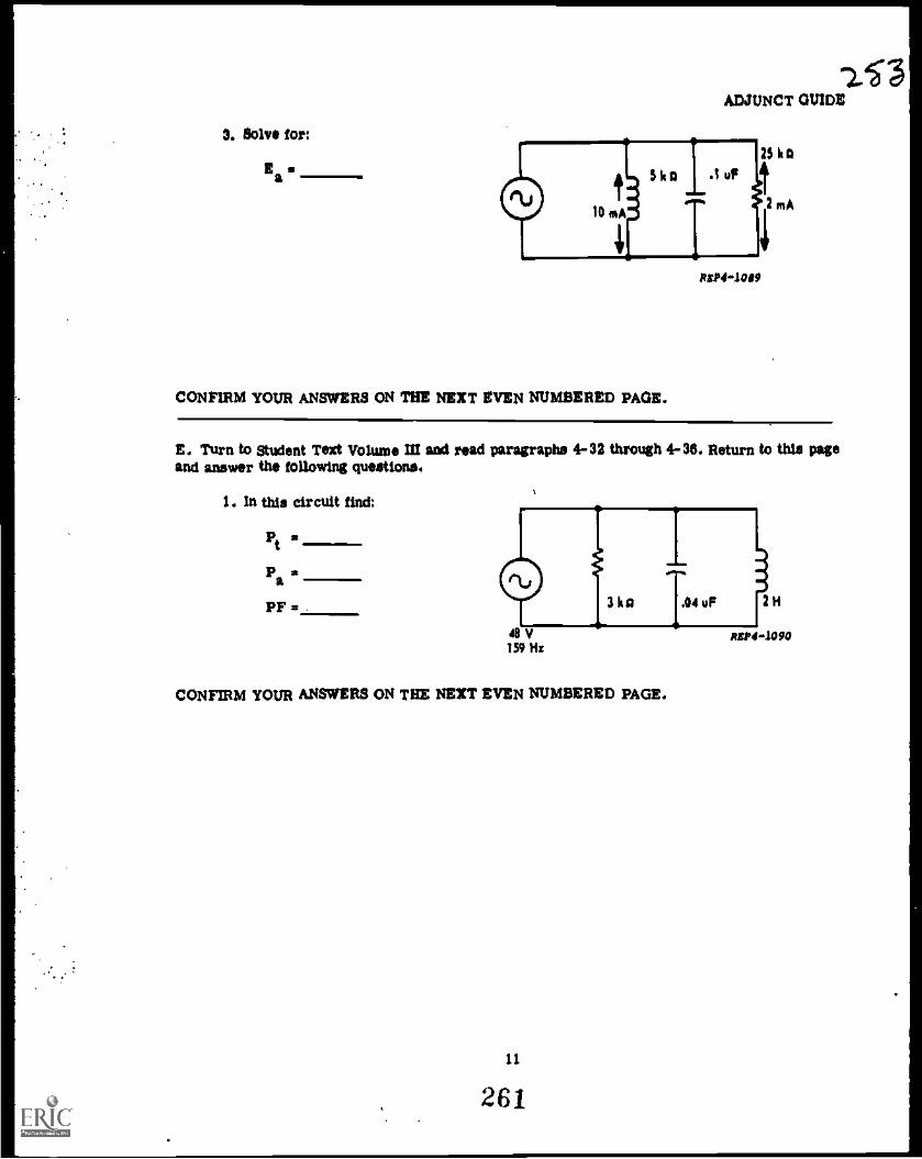
3. Solve for:
ADJUNCT GUIDE
25 k0
2 nsA
RSP44009
CONFIRM YOUR ANSWERS ON THE NEXT EVEN NUMBERED PAGE.
E. Turn to Student Text Volume III and read paragraphs 4-32 through 4-36. Return to this pageand answer the following questions.
1. In this circuit find:
Pt m
Pa
PF =
CONFIRM YOUR ANSWERS ON THE NEXT EVEN NUMBERED PAGE.
11
261

ADJUNCT GUIDE
ANSWERS TO Dt
1. 3 mA
/C un/A
It a 3 mA
Z 42.4 k g
It 4.24 mA
9 =46°
2. Z a6kg
3. Ea =50V
If You missed ANY questions,
VECTOR DIAGRAM
4.10 WM MO Ma .10 MN.
43°
review the material before you continue.
t
EaIR ER
ECEL
R2P4.1109
ANSWERS TO E:
1. Pt = 766 mW
Pa 960 m VA
PF = .7997
If you missed ANY questions, review the material before you continue.
YOU MAY STUDY ANOTHER RESOURCE OR TAKE THE MODULE SELFCHECK.
12
262

MODULE SELF' CHECK
PARALLEL RCL CIRCUITS
QUESTIONS:
I. Solve for;
IR aPt
1C Pa
ItPF
Z 0 197 V CI klis i 2 k a .0099 uF
XcASP41091
Draw the current vectors.
2. It the capacitor in problem one was replaced by a 1 pF unit, lc would
and EC would
3. Solve for:
X
1L =
-Z *
1111111
Draw the current vectors.
Pt
Pa
PP a
9
13
263
120 V60Hz
814 OoRIP4 -1092
25 5

MODULE BULL' -CHICK
4. If the frequency of the generator in problem three le decreased, the applied voltage would
5. Solve for:
Pt
Papp a
Z a L a
Draw the current vectors.
8. U the core of the coil in problem five is replaced by a material having a higher perm's-
bility, EL would and It would .
7. Solve for.
Z = Pa =
PXC = F a
C = IR =E Aa IC =0 =
Draw the current vectors.,,
14
2C4
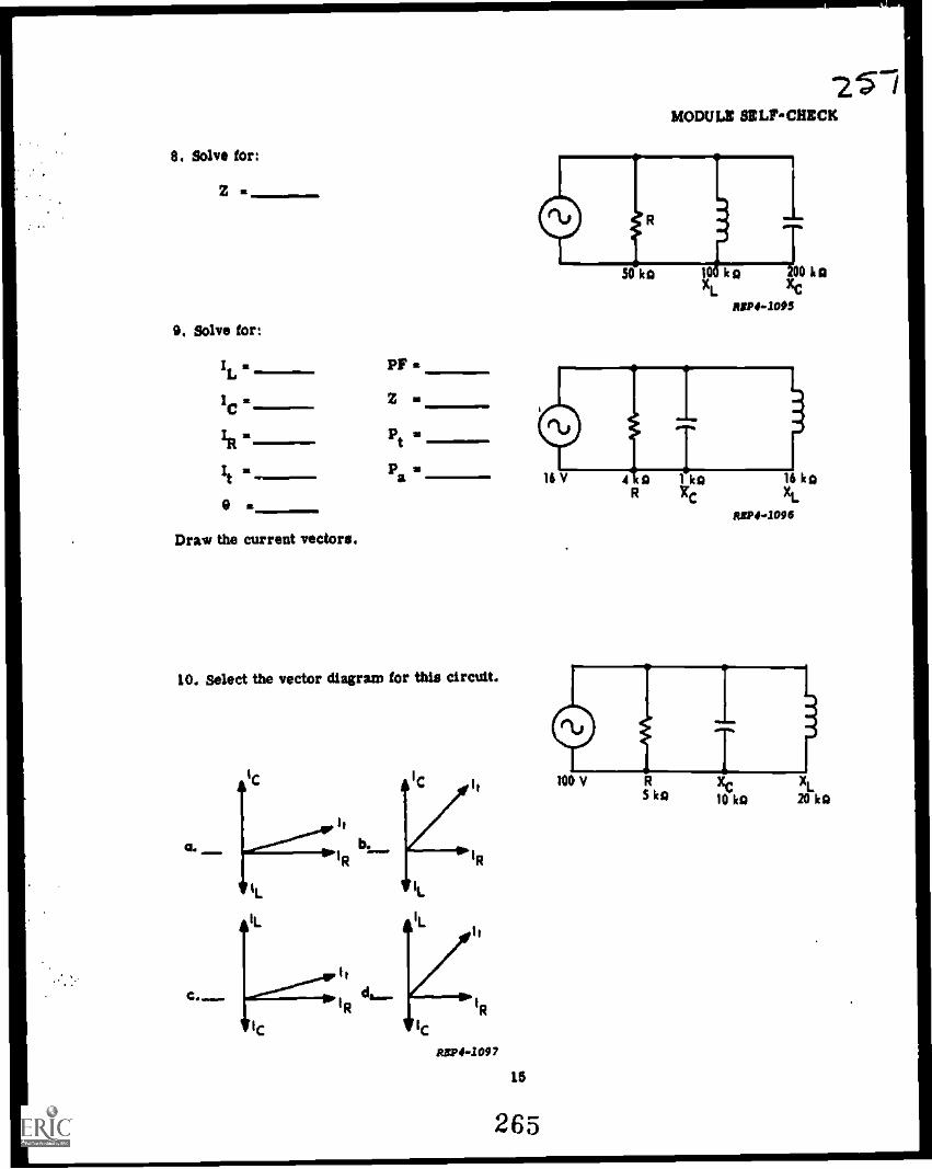
O. Solve for:
Z st
O. Solve for:
It a
IC a
IR a
Ite
Draw the current vectors.
PF
Z
Pt u
Pa
10. Select the vector diagram for this circuit.
IC
1,
SIR
TIC
RBP44097
15
265
MODULI: BELFCMCCK
50 ka ko kpAC
R119440114

MODULE SELF-CHECK
11. The total impedance is
a. k ohms
b. 9.9 k ohms
c. 8.9 k ohms
d. 12 k ohms
$4VkA
12. The reading on the ammeter has increased. What is the trouble?
a. Ea has decreased.
b. The resistance of the resistor hasincreased.
C. The coil has opened.
d. The capacitor has opened.
13. Total impedance is
a. 5 k
b. 10 k ohms.
c. 15 k ohms.
d. 20 k ohms.
14. In this circuit,
a. R = Xc.
b. Xc is leas than EL,
c. laga Ea'
d. IR leads Ea.
12 ke 42 ko
RIP41091
ASP4-.1099
REPO -1100
REPO -1101
3 mA

15. Solve for:
IC . Pt .Ps .
Ea= PT
0 =
Z =
Draw the current vectors.
16. Solve for:
Pt .Pa a
PF a
0 =
Z =
Show vectors.
17. Solve for:
Ea =
Z=
Show vectors.
21-MODULE SE LFCHE QC
0310 Hs
017mA
12 V159 Rs
dmi II M.
0.05 u?
R T8 ka xC10 ha
20 mA
3H
XL6 ha
REP4-1102
s
IND159 Rs
1c 5 at
CONFIRM YOUR ANSWERS ON THE NEXT EVEN NUMBERED PAGE.
17
267
/I. . 1 0A
2H
50 a

MODULE SELF-CHECK
ANSWERS TO MODULE SELF -CHECK
I. iR 15 mA Pt 3072 naVi lc 12mA
lc 12 mA p 3640 naVA
it 20 mA PF .5
Z 9,5 ha a 35.5°
Xc MO
2. iC decreases and EC remains the stuns.
3.XLas3k9
IR 30 mA
IL 40 mA
It 50 inA
Z 2.4 kg
Pt 3.5 W
Pa 5 VA
PF $2 .5
I 53.1'
4. Voltage would remain the same.
5. IL = 10 mA Pt =2W
1E2120 mA Pa 2= .22 VA
it = 22.3 mA PF 2 .5960
Z =4.45kg L = 25.5 N
= 25.4*
6. E would remain the same and it woulddecrrase.
7. Z =6kn pa 600 mVA
X c=7.5kil PF .5
C =133pV IR = mA
Ea = 50 V lc ate mA
=53.1 °
VIL 40 /NA
IR 30 mA
20 mA
IR 16 mA
SEP4..1103
SO ntA itsP4-2101
ASP44.106
IS
268
2)
1

20MODULE SELF' CMICK
ANSWERS TO MODULE SELF CHECK (Continued)
8. Et 48.5 k II
9. IL = I mA PT * .2580
lc a le niA Z * 1.03 lc El
1R4mA pt a 84 mW
Pa a 248 mVAIt 15.6mA
9 a 756
10. a
11. C
12. c
13. d
14. b
15. IR st 15 mA
lc = 12 mA
R =Okla
Za = 120 V
F =318 Ha
Z = 7.05 k CI
16. Pt = 48 npl,
Pa = 80 mVA
PF = .8000
0 = -38.96
Z =2.4 Irct
L = 3 II
; =1800 inW
Pa = 3040 mVA
PF :.8823
9 =28.1'
16 mA
IC 12Aa
IL -Ic
It 1S.S mA
1R 4 mA
R1V4-1107
. i ..= ..
a. IR IS mA
t I/ mA
T IL 20 mA REPS -110
IC it 3 al
XR = 4 mi
I;= Satit; -rc 3 "
Xt. ag 6 al
19
269

MODULE SELFCHECK
ANSWERS TO MODULE SELFCHECK
lie Ea 50 V
2 10 1c41.
le 5 sik
To Ive 4 al ha 5 14
&Ins 3mit
IL me I at
Ve 2
HAVE YOU ANSWERED ALL OF THE QUESTIONS CORRECTLY? IF NOT, REVIEW THEMATERIAL OR STUDY ANOTHER RESOURCE UNTIL YOU CAN ANSWER ALL QUESTIONS
CORRECTLY. IF YOU HAVE, CONSULT YOUR INSTRUCTOR FOR FURTHER GUIDANCE.
20
270
24;3ATC PT 3AOR3X020-1
Prepared by Kessler TTCKEP-PT-23
Technical Training
Electronic Principles (Modular Self-Paced)
Module 23
TROUBLESHOOTING SERIES AND PARALLEL RCL CIRCUITS
(Troubleshooting Capacitors and Inductors)
ATC Keeler 11.2375
November 1975
AIR TRAINING COMMAND
7-7Dosigned For ATC Course Us.
DO NOT USE ON THE JOS
271

RADAR PRINCIPLES BRANCHKessler Air Force Base, Mississippi
Guidance Package KEPPT233AQR3X020
November 1975
TROUBLESHOOTING SERIES AND PARALLEL RCL CIRCUITS
(TROUBLESHOOTING CAPACITORS AND INDUCTORS)
Module 23
This text is designed so that you will go through it step by step.Each step of instruction is designed to teach a small bit of information.Answers to the questions for each step are given at the top of the nexteven numbered page (blocked).
Read the information on the next even numbered page and respond asyou are directed. Confirm your responses. Do not proceed until you haveresponded correctly. If you require assistance, see your instructor.
CONTENTS
TITLE PAGE
Introduction 1
Troubleshooting Capacitors 2
Troubleshooting Inductors 13
Supersedes KEP-PT-23, 5 November 1974. Previous editions may be used.
i
272
2.44

TROUBLESHOOTTNO CAPACITORS AND INDUCTORS
INTRODUCTION
In electronic circuits, capacitors and inductors, like resistors,
become defective and must be isolated and replaced. Defective resistors
can usually be identified Way conolusively with the ohmmeter; however,
this is not the case with capaoitars and inductors. It usually requires
more careful attention to the troubleshooting procedures In order to
identify defective capacitors and inductors than it does to detect
defective resistors.
The troubleshooting procedures that can be used to isolate
defective capacitors and inductors are presented in this text. The
material is divided into two Farts. The procedures for troubleshooting
capacitors are in the first part and the procedures for troubleshooting
inductors are in the second part.
The material is presented in steps with questions separating
the steps. Respond to these question' and be sure you know the answers
to these questions before advancing to the next step.
1
273
.2(6

2V9
TROUBLESHOOTING CAPACITORS
That can cause a capacitor to become defective? Although there
are others, these are some of the more frequent causes: (1) Voltage
surges that exceed the WVDC rating of the capacitor produce an arc of
current through the dielectric material, partially or completely
destroying the dielectric; (2) high temperature or the frequent changes
in temperature cause expansion and contraction within the capacitor,
causing the leads to separate from the plates; (3) moisture gets
inside the capacitor (paper capacitors are very susceptible to moisture)
and destroys the dielectric material; and (4) some dielectric material -
usually the electrolyte in the electrolytic capacitor - deteriorates
with age or long storage time.
More important than the causes of capacitor failure is the types
of failures that they produce. Voltage Barges and moisture in a
capacitor normally cause a SHORTED or mar condition. High
temperature or frequent changes in temperature sometimes cause an
OPEN condition. The three types of failures discussed in this text
are: (1) the SHORTED capacitor; (2) the OFEN capacitor; and (3) the
LEAKY capacitor.
Some of thA test instruments that can be used to troubleshoot
capacitwz are the capacitor checker (which is rarely available to the
technician), voltmeter, ammeter, and ohmmeter.
2
274

Usually, the olimmerra is preferred over all the other test
instruments. It is the easiest to use and will yield more information
about the condition of a capacitor in less time than any of the other
instruments. The OHMMETER will be used in all further discussion
on the troubleshooting of capacitors and the ohmmeter section of
the P314 -6 will be used in all examples.
QUICK QUIZ 1.
1. This text will discuss the that can be used
to isolate defective capacitors.
2. In troubleshooting capacitors, the three most common types of
failures likely to be encountered are the,
and capacitor.
3. The test instrument usually preferred over other types to
troubleshoot capacitors is the:
a. voltmeter c. ohmmeter
b. ammeter d. oscilloscope
Check your answers on the next even numbered page.
When used to check capacitors, the ohmmeter has a number of
limitations that one must know in order to make the best use of the
ohmmeter. These limitations are: (1) the ohmmeter cannot be used to
measure the amount of capacitance (in farads) of a capacitor; (2)
capacitors with very SMALL capacitance (less than .001 microfarads)
cannot be effectively checked for an OPEN condition; (3) the LEAKAGE

vANSWERS TO QUICK WIZ 1.
1. procedures
2. open, short, and leaky
3.
test on an electavolytio capaoitor is usually not reliable (all
electrolytic capacitors have some allowable leakage according to
their capacitance); (4) capacitors with a WITDC rating less than the
internal power source of the ohmmeter should not be cheoked; and
(5) capacitors are not checked at their full WVDC rating.
If the condition of a suspect capacitor cannot be determined by
using the ohmmeter, the normal procedure is to replace it with one
known to be GOOD. This usually requires less time and effort than
to obtain the test equiment necessary to perform elaborate checks
on a relatively inexpensive component.
QUICK QUIZ 2.
1. The ohmmeter cannot be used to measure the of a
capacitor.
2. Capacitors with very capacitance cannot be effectively
checked for an open condition with the ohmmeter.
3. If the condition of a suspect capacitor cannot be determined with
the ohmmeter, it should be replaced with a capacitor known to
be
Check your answers on the next even numbered page.
4
276

The order in which a capacitor is checked for a SHORT, OPEN, or
LEAKY condition is not important. To establish a pattern for the
purpose of explanation only, the ensuing discussions will be in the
following order: (1) the oheok for a SHORTED oondition; (2) the
check for an OPEN condition; and (3) the cheok for a LEAKY oondition.
A capacitor that is neither SHORTED, OPEN, nor LEAKY can usually be
considered to be a GOOD capacitor.
Before making any tests with the ohmmeter, it is VERY IMPORTANT
that power be removed from the circuit being checked and all capaoitors
should be discharged by connecting a wire across their terminals. Also,
for the ohmmeter indications to be meaningful, the capacitca, must be
isolated from the other components in the circuit.
5/1
If the capacitor is connected in series with other components,
it can be isolated by opening the oircuit at any point. In other words,
the current from the ohmmeter can have only one path, into and out of
the capacitor. In a simple series circuit as shown in Figure 1-1, the
capacitor is isolated and the power source is removed whenever the switch
is open. If no switch is provided, the circuit must be disconnected frog
the power source.

ANSWERS TO QUICK QUIZ R.
1. capsoitime.
2. small.
3. good.
Figure 1-2 is a simple parallel circuit. Power can be removed
from the circuit by opening the switch. If no switch is provided,
the circuit must be disconnected from the source; also, one lead of the
capacitor MUST be disconnected from the circuit to isolate the capacitor.

QUICK QUIZ 3.
1. To prevent damaging the ohmmeter, must be removed
from the circuit to be °hooked.
2. For the ohmmeter reading to be meaningfUlt the capacitor must
be
3. A capacitor that is neither shorted, open, nor leaky can usually
be considered to be capacitor
Check your answers on the next even numbered page.
After the power has been removed from the circuit and the capacitor
isolated from the other components, the next step is to prepare the
ohmmeter so that it will indicate the smallest amount of resistance.
This is done by setting the range switch to the lowest-ohm position
(1121) and calibrating the meter; then, the ohmmeter leads should be
connected to the capacitor as shown in Figure 1-3. It is not necessary
to observe polarity.
Figure 1 -3
7
279

272.ANSWERS TO QUICK QUIZ 3.
1. power.
2. isolated.
3. good.
A reading of ZERO OHM indicates that the dielectric material has
completely br9ksn down and is allowing current to pass between the
plates. This condition is termed a SHORTED capacitor.
The next check is for an OPEN capacitor (0010 or larger).
Prepare the ohmmeter by setting the range
switch to the highest-ohm position (R X 10,000 ohms)
and calibrating the meter. As in the previous step, the ohmmeter ie
connected to the capacitor; however, it is very important that the
ohmmeter needle be observed very closely at the instant the leads are
connected to the capacitor. This step should be repeated two or three
times, reversing the ohmmeter leads to the capacitor each time the step
is repeated. If the ohmmeter needle remains at infinity and DOES NOT
deflect up-scale as show' in Figure 1-4, the capacitor is OPEN.
Figure 1-4
8 nc0

QUICK QUIZ 4.
1. To ohsok a ospaoitor for a shorts the ohmmeter range switch should
be set to the:
a. fiX1 position. o. r41000 position.
b. 11K10 position. d. 11X10,000 position.
2. A zero -ohm reading on the ohmmeter indicates a oondition
for a capaoitor..
3. To cheok a capaoitor for an opens the ohmmeter range switch should
be set to the:
a. 11X1. position.
b. 11310 position.
0. A.X1000 position
d. 11.X10,000 position.
4. When troubleshooting a capacitors the needle of the ohmmeter remains
at infinity and does not deflect up-scale. The capacitor is:
a. shorted. b. open. c. good.
Check your answers on the next even numbered page.
The last check to be performed on a capacitor is probably the most
important test of all--the test for LEAKAGE. SUM no dielectric
material is a perfect insulators all capacitors have an allowable
leakage (current flow) between their plates. Only when this leakage
becomes excessive is a capacitor considered to be defective. This
leakage varies directly accoriing to the capacitance of a capacitor.
The ohmmeter will indicate this leakage as resistance; therefore, since
most capacitors have very small leakage currents, the ohmmeter will
indicate every HIGH resistance for a GOOD capacitor.

ANSWERS TO QUICK QUIZ 4.
1. a.
2. shorted
3. d
4. b
To test for LEAKAGE, the ohmmeter is set to the highest ohm
position (RX10,000 ohm) and connected to the capacitor in the same
manner as for the SHORT, or OPEN test. Any steady resistance reading
on the ohmmeter as shown in Figure 1.3 indicates that the capacitor
being checked is a LEAKY capacitor. Remember, this tee, DOES NOT
apply to an electrolytic capacitor. For the LEAKAGE test the hands must
not touch the capacitor leads.
Figure 1 -5
A GOOD capacitor can also be checked because a good
capacitor will give a definite indication on the ohmmeter. As for the
open and leakage check, the ohmmeter is set to the 8110,000 ohm position
and the ohmmeter needle observed very closely at the Instant the leads
are connected to the capacitor. As shown in Figure 1-6, the needle
10
252
27

should deflect up-scale (toward sera ohm) and then drop baok to
infinite mistime. The leads should be reversed two or three times
to insure that the capacitor is discharged.
Figure 1-6
QUICK QUIZ 5.
1. Leakage current is read on the ohmmeter as:
a. voltage b. current. c. resistance.
2. To test for leakage, the ohmmeter should be set to the:
a. Oil position
b. fa10 position.
c. 11.7[1000 positiou.
d.rialo,000 position.
3. Which reading indicates a lea) capacitor?
a. zero ohm b. 5000 ohm c.
A. With the ohmmeter range on RX10,000 which capacitor would cause the
ohmmeter needle to deflect up-scale and then drop back to infinity?
a. A good capacitor. c. A shorted capacitor.
b. a leaky capacitor. d. An open capacitor.
Check your answers on the next even numbered page.
11
283

ANSWERS TO QUICK QUIZ 5.
1. c 3. b
2. d 4. a
In eummary, as a capaoitor checker, the ohmmeter is a very useful
instrument. It cannot be used to check all capacitors for each type
of failure. However, a capacitor that cannot be checked ocmpletely
should be replaced with one known to be GOOD. Again, in preparing the
circuit, remove power to the oircuit and isolate the component. In
many cases, to isolate the capaoitor, simply remove it from the circuit.
Remember, a zero-ohm reading on the ohmmeter indicates a SHORTED
capacitor; an infinite reading with no momentary up-scale deflection
of the ohmmeter needle indicates an OPEN capacitor; a steady resistance
reading other than infinity or zero -ohm, indicates a LEAKY capacitor;
and a reading of infinity after a momentary up-scale deflection indicates
a GOOD capacitor.
12
284

TROUBLESHOOTING INDUCTORS
An inductor is a oiromit oomponent designed so that inductenoe
is its most important property. Coils and ohokes are designed so
that they present a speoified amount of inductance to a oircuit;
however, audio and power transformers,,voice ooils in speakers, field
and armature windings in motors for all practical purposes of trouble-
shooting can be treated exactly the same as coils and chokes.
Inductors do fail and since they are an integral part of many
electronio circuits, they must be checked to determine their condition.
The most common types of failures that occur in inductors are: (1)
OPEN windings; (2) SHORTED turns; (3) winding to core shorts; and
(4) SHORTS between /windings.
Although there are test instruments designed specifically for
testing the different types of inductorschokes, transformers, motor
windings, etc. -- usually the OHNMETER is used to perform the
preliminary checks on an inductor suspected of being defective.
Again, to make the best use of the OHMMETER, its limitations
must be known. As an inductor tester, its limitations are these:
(1) the ohmmeter CANNOT be used to measure the inductance of an
inductor; and (2) shorted turns in inductors are difficult to locate
with the ohmmeter.
13
285
211

27'SQUICK QUIZ 6.
1. The test instrument that is usually used to make preliminary checks
on inductors 'mooted of being defective is the:
a. ohmmeter. b. voltmeter. o. ammeter.
2. The ohmmeter CANNOT be used to measure the of an
inductor.
3 Usually, a defective inductor has:
a. increased in inductance.
b. shorted or open winding.
c. become resonant.
Check your answers on the next even numbered page.
The first step in any troubleshooting procedure in which the ohmmeter
is utilized is to MOVE power to the circuit. Secondly, isolate the
inductor from the other components in the circuit in the same manner
as when troubleshooting capacitors.
After the power has been removed from the circuit and the inductor
isolated from the other components, the next step is to prepare the
ohmmeter so that it will indicate the maximum amount of resistance.
This is done by setting the range switch to the highest...dm position
(RX10,000) and calibrating the meter; then, the ohmmeter should be
connected to the inductor as shown is Figure 2-1.
An infinite resistance reading on the ohmmeter indicates that the
. inductor is definitely OPEN.
14
286

211
Figure 2-1
QUICK QUIZ 7.
1. Before troubleshooting inductors with an ohmmeter, the
must be removed and the component
2. To check inductors for open windings, the ohmmeter range switch
must be set to the:
a. ftUO position. c. ILX1000 position.
b. 0;1100 position. d. L1X10,000 position.
3. A reading of infinite resistance on the ohmmeter indicates that an
inductor ham
a. open winding.
b. shorted winding.
c. leaky winding.
Check your answers on the next even: numbered page.
15
287

ANSWERS TO QUICK QUIZ 6.
1. a
2. inductance.
3. b
ANSWERS TO QUICK QUIZ 7.
1. power, isolated.
2. d
3. a
As stated previously, one 'Imitation of the ohmmeter is that it
cannot be used to check all inductors for shorted turns. For example,
an inductor wound with a few turns of large copper wire, such as RF
coils, will indicate zero resistance on the ohmmeter even on the,011
range. Thus a shorted turn in this type of inductor cannot be detected
with the o'....ineter. However, some inductors CAN be checked for shorted
turns. If tt. -Jading resistance is sufficiently high to be measured
with the ohmmeter and if the resistance is known, an inductor of this
type can be checked for shorted turns.
Figure 2-2 shows an example of a transformer that has shorted turns
in the secondary winding. The ohmmeter indicates 500 ohms which is a
decrease of 250 ohms from the 750 ohms specified for the secondary
winding of the transformer. A decrease In resistance much less than
the amount shown in Figure 2-2 would still indicate shorted turns In the
transformereven a decrease of a few ohms of resistance.
16
28s
lo

Figure 2.2
QUICK QUIZ 8.
1. Select the inductor(e) that could be checked for shorted turns
with the ohmmeters
a. b. c. d.
JII iii icu'is
2. An (A) (increase/decrease) in winding resistance indicates
shorted turns.
Check your answers on the next even numbered page.
17
289

ANSWERS TO QUICK QUIZ S.
1. b
2. a decrease.
Another type of short that can be detected with the ohmmeter is
a short between the turns and core material. Of course, this type of
short can only occur in an inductor having an iron core. To check an
inductor for winding-to-core shorts, connect the ohmmeter leads between
the core and winding as shown in Figure 2-3. Since GOOD inductors
have infinite resistance between the core and windings, any resistance
reading on the ohmmeter other than infinity indicates a defective
inductor.
Figure 2-3
2018
212-

Last, a type of short that occurs in inductors with multiple
windings, such as transformers, is the short between windings. In
transformers, the windings are ultual4 wound very tightly, one upon
the other; therefore, if the insulating material should fail, a abort
will occur between the windings. Shorts between winding° can be
detected with the ohmmeter. To test for ehorte between windings of an
inductor, connect the ohmmeter leade between windings as shown in
Figure 2-4. A resistance measurement must be made between each set
of windings in turn. GOOD transformers have infinite resistance
between windings; therefore, any resistance reading other than
infinite indicates a defective transformer. (See Figure 2-4)
Figure 2-4
19
291
QUICK QUIZ 9.
1. A good inductor should have (infinite, low) resistance between
its core and windings.
2. The ohmmeter (can, cannot) be used to detect shorts between
the windings of an inductor with multiple windings.
Check your answers on the next even numbered page.
How do you troubleshoot an inductor suspected of having a short
and yet the ohmmeter indications are inconclusive? If the inductor
is expensive, requires a great amount of time to replace, and is not
readily available, check all the other components associated with the
inductorif they are good, the inductor must be defective. An
excellent check for any inductor suspected of being defective is to
substitute it with a NEW inductor.
QUICK QUIZ 10.
1. When troubleshooting inductors with the ohmmeter, it is difficult to
detect:
a. open windings.
b. shorted turns.
2. Name ONE method of Checking an inductor without the use of an
ohmmeter.
Check your answers on the next even numbered page.
20 214
21 4


ANSWERS TO QUICK QUIZ 9.
1. infinite.
2. can.
ANSWERS TO QUICK QUIZ 10.
1. b
2. substitution.
This programmed text is not complete until after you have completed
laboratory exercise 23-1. Upon completion of the laboratory exercise
steps, confirm your answers by using the ohmmeter to check each
component. Remember, power mast be removed and the component
isolated (disconnected) before the ohmmeter is used.
YOU MAY STUDY ANOTHER RESOURCE OR TAKE THE MODULE SELF-CHECK.
22
2 .0 4

\\ #PNIPANI ,,,_'1 TN. MAN
.., Prepared by Kessler TTC, ..KEP-GP-24
-2.q 54ATC ST 3A0113X020-X
ATC. er 6-1521
Technical Training
ELECTRONIC PRINCIPLES (MODULAR SELF-PACED)
MODULE 24
SERIES RESONANCE
1 October 1975
MR TRAINING COMMAND
. 7 7Designed For ATC Course Use
DO NOT USE ON THE JOB
P.

Basic and Applied Electronics DepartmentKessler Air Force Bass, Mississippi
ATC GP 3AQR3X020-XKE P-OP- 24
October 1975
ELECTRONIC PRINCIPLES (MODULAR SELF-PACED)
MODULE 24
SERIES RESONANCE
This Guidance Package is designed to guide you through this module of the ElectronicPrinciples Course. It contains specific information, including references to other resourcesyou may study, enabling you to satisfy the learning objectives.
CONTENTSPAGE
Overview iList of Resources 1
Adjunct Guide 1
Laboratory Exercise, 24-1 6Module Self-Check 7
Answers
OVERVIEW
1. SCOPE: If the frequency applied to aseries RCL circuit is varied, the inductivereactance can be made to equal the capacitivereactance. When this occurs, we haveresonance. This module discusses the condi-tions that exist when the series circuit isresonant. Resonant circuits are used in radio,radar, and telephone circuits to separatesignals in terms of frequency. Practicaltraining to determine bandwidth, bandpass, andresonant frequency completes the module.
2. OBJECTIVES: Upon completion of thismodule you should be able to satisfy thefollowing objectives:
a. Given the response curve of a seriesRCL circuit, compare the magnitude of currentflow at resonance and off-resonance.
b. Given a series RCL circuit, and vectorrepresentations of current and voltage, select
the representation which shows current andvoltage relationships
(1) below resonance.(2) above resonance.(3) at resonance.
c. Given a series RCL circuit and for-mulas, determine the effects on current,impedance, and phase angle by varyingindividually
(1) frequency.(2) resistance.(3) capacitance.(4) inductance.
d. Given component values of a seriesRCL circuit, calculate the resonant frequency.
e. Using a series RCL circuit connectedon a trainer, signal generator, and multi-meter, determine the half power points, band-width, bandpass, and resonant frequency.
Supersedes REP-GP -24,15 May 1975 which may be used until stock is exhausted.
2%

LIST OF RESOURCES I. What is the definition of aeries resonance?
To satisfy the objectives of this module,you may chOose, according to your training,experience, and preferences, any or all ofthe following;
READING MATERIALS:
DigestAdjunct Guide with Student Text, Vol M
AUDIO - VISUALS:
Television Leeson, Series RCL Circuits(Resonance), TVK 30-360
LABORATORY EXERCISE:
Series Resonance 24-1
AT THIS POINT, IF YOU FEEL THATTHROUGH PREVIOUS EXPERIENCE ORTRAINING YOU ARE FAMILIAR WITHTHIS SUBJECT, YOU MAY TAKE THEMODULE SELF-CHECK. IF NOT, SELECTONE OF THE RESOURCES AND BEGINSTUDY. CONSULT YOUR INSTRUCTORIF YOU NEED HELP.
3. Referring to the graph, which point isconsidered to be resonance?
-. a. Point A.
---. b. Point B.
--- c. Point C.
REPO -2124
3. How does a series RCL circuit act whena frequency below the resonant frequency isapplied:
ADJUNCT GUIDE a. Capacitive.
INSTRUCTIONS: -- b. Inductive.
Study the reference materials as directed. -. c. Resistive.
Return to this guide and answer the 4. How does a series RCL circuit act whenquestions. a frequency above the resonant frequency is
applied?Confirm your answers at the back of this
Guidance Package.
If you experience any difficulty, contactyour instructor.
Begin the program.
A. Turn to Student Text Volume M andread paragraphs 5-1 through 5-14. Returnto this page and answer the followingquestions.
I
-- a. Capacitive.
.--. b. Inductive.
- c. Resistive.
5. Which of the following is NOT a conditionor characteristic of series resonance?
- a. Xc = XLb. Z = R

...... c. Z is minimum
.._, d. I is maximum
......-.. e. Ea, a Ec
..--.... f. ER s Ea
g. EC *EL
h 0 s 0°
i. Pa s Pt
6. How does a series RCL circuit act atthe resonant frequency?
a. Capacitive.
Inductive.
c. Resistive.
7. If opposition to current at resonance isminimum, what is the condition of currentin the series RCL circuit at resonance?
8. For any given RCL circuit, how manydifferent frequencies will cause a resonantcondition?
a. One.
b. Two.
c. Three.
9. if you have an RCL circuit acting capaci-tively, what three parameters can be changedto make the circuit act as a resonant circuit?
10. Identify the following vectors andindicate whether they represent a series RCLcircuit at resonance, above resonance,or below resonance.
a.
XL
xcRSP4 -2226
b.
XL
1
c.
Txc
R Z
REP4112S
CONFIRM YOUR ANSWERS
B. Turn to Student Text Volume In andread paragraphs 5-11 through 5-22. Returnto this page and answer the following questions.
1. Solve for the resonant frequency whenL is 10 mH and C is 1 gF.
2 298
211

2. Solve for the resonant frequency when C. Turn to Student Text Volume III andI., is 2.5 mH and C is 16 Or. read paragraphs 543 through 5-43. Return to
this page and answer the following questions.
3. Solve for the resonant frequency when 1. Solve for:L is 501 and C is 5pF.
4. Solve for the resonant frequency in thefollowing circuit.
3 mH
120,F
TOO
REPO -2127
5. The following chart is a graphic illus-tration of the different quantities in a seriesRCL circuit. Match each curve with thequantity it represents.
a. Curve A (1) I.
b. Curve B (2) XC-c. Curve C
(3)
(4)
Z
XL
d. Curve D (5) E-.
40'
'...0 ....:."'
- Co
f,
REPO -1128
CONFIRM YOUR ANSWERS.
3
fr
I.-
0=
28 H
REPO -1129
2. Draw the vectors for this circuit.
40 Ca
299
2012
REPO -1130

3, Select the proper vectors for this circuit.(Ea is to be used as a reference')
80a
.._ a.EL
%Ea
b.
ER
..--..EL
.. 4. -
Ec
II
- Es
Ec ER
EL
M.M. I.& .. Ea
ER
I EcEc
4. The circuit in question 3 is acting:
a. Capacitively and operatingabove resonance.
b. Inductively and operatingabove resonance.
,.... o. Capacitively and operatingbelow resonance.... 4. Inductively and operatingbelow resonance,
II. Select the proper vectors for this cir-cuit, (I is to be used as a reference.)
3 L'0
4
emmIrml a.
M.= b.
120 a
60 0
EL
>cEREs
Ec
c4 EL
Eszi
I ER
EC
1

ER
10. What is meant by the term BANDPASS?
EaCONFIRM YOUR ANSWERS
Et
6. The circuit in question 5 is acting:
a. Capacitively, and operatingabove resonance.
b. Inductively, and operatingabove resonance.
c. Capacitively,below resonance.
,___ d. Inductively,below resonance.
and operating
and operating,
7. What are the HALF POWER POINTS?
8. What formula is used to determine thecurrent at the HALF POWER POINTS?
-- a. .637 times 1 maximum.
-. b. .707 times I maximum.
-- c. 1.414 times I maximum.
_. d. 1.57 times I maximum.
9. What is meant by the term BANDWIDTH?
D. Turn to Laboratory Exercise 24-1. Thisexercise will familiarize you with the pro-cedure for determining the bandwidth, band-pass, half power points, and resonant fre-quency of a series RCL circuit. Return andcontinue with this program upon completionof this exercise.
H. Turn to Student Text Volume III and readparagraphs 5-44 through 5-47. Return to thispage and answer the following questions.
30 0
REP41135
1. Using the circuit above, fill out the chartbelow. Indicate an increase, decrease, orremain the same for each value asfrequency, resistance, capacitance, orinductance is individually varied as indicated:
Increase tDecreaseRemain the same 411'
t
FREQ
RES
CAP
-IND f
2Mb.
. -
CONFIRM YOUR ANSWERS
3 o 1
ao 1
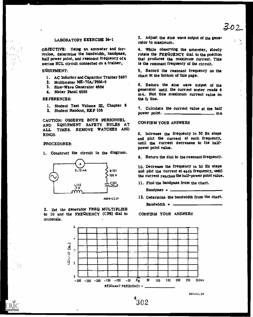
LABORATORY EXERCISE 441
OBJECTIVE: Using an ammeter and for-mulas, determine the bandwidth, bandpass,half power point, and resonant frequency of aseries RCL circuit connected on a trainer,
EQUIPMENT:
1. AC Inductor and Capacitor Trainer 50672. Multimeter ME- 70A/PSM -63. Sine-Wave Generator 46644. Meter Panel 4566
RE FERENCES:
1. Student Text Volume III, Chapter 52. Student Handout, KEP 108
CAUTION: OBSERVE BOTH PERSONNELAND EQUIPMENT SAFETY RULES ATALL TIMES. REMOVE WATCHES ANDRINGS.
PROCEDURES:
1. Construct the circuit in the diagram.
REP44137
2. Set the generator FREQ MULTIPLIERto 10 and the FREQUENCY (CPS) dial tomidscale.
d
0
3. Adjust the line wave output of the gene-rator to maximum.
4. While observing the ammeter, slowlyrotate the FREQUENCY dial to the positionthat produces the maximum current. Thisis the resonant frequency of the circuit.
5, Record the resonant frequency on thechart at the bottom of this page.
6. Reduce the sine wave output of thegenerator until the current meter reads 4met. Plot this maximum current value onthe fr
7. Calculate the current value at the halfpower point. mA
CONFIRM YOUR ANSWERS
6. Increase the frequency in 50 Hz stepsand plot the current at each frequency,until the current decreases to the half-power point value.
9. Return the dial to the resonant frequency.
10. Decrease the frequency in 50 Hz stepsand plot the current at each frequency, untilthe current reaches the half-power point value.
11. Find the bandpass from the chart.
Bandpaes
12. Determine the bandwidth from the chart.
Bandwidth s
CONFIRM YOUR ANSWERS
I1
,. ,
. r-.i -
r
I-, r
- -.N.
_I_ _d_
onn let Itin _f so _tee so Fri 50 ion 15o 200 250 30
RESONANT FREQUENCY =
6302
01i:
REP41:39

31)MODULE SELF-CHECK 5. Solve for the resonant frequency when L
is .3 mH and C is 12 pF.QUESTIONS:
1. Series resonance occurs in an RCL cir- itcult when:
.. a. the phase angle between XCand R is exactly 90°.
b. XL - XC.
.1.1O c XL is exactly five times asgreat as XC.
.---- d. XC is exactly five times asgreat as XL.
2. At resonance in a series RCL circuit
a. currant is minimum.
b. impedance is maximum.
c. voltage across the coil isminimum.
d. current is maximum.
3. Solve for:
fr =
Ska
26 H
REPS -1121
4. At resonance angle theta equals
n. 0°
--.. b. 45°
C. 90°
8. if resonant current is 10 mA, what isthe half power point current?
....... a. 2.5 mA
b. 5 mA
c. 7mA
....-- d. 10nIA
7. Solve for:
R
fr =
Z.=
I =
3 inft
.3 uP
d. 180°. 0 -
7
11111
4

8. Reference problem '7. A voltmeter placedacross both the capacitor and the coil whilethe circuit is at resonance would indicate:
a. 0 volts.
---. b. 500 volts.
c. 1000 volts.
d. 3000 volts.
9. Identify the curve representing currentbelow, at, and above resonance.
REP4.1140
- a. Curve A
b. Curve B
Curve C
d. Curve D
10. U the frequency to a series resonantcircuit is increased, what effect would therebe on the following values?
Increase ( 41 )Decrease ($ )Remain the same (4. )
z
9
6
11. Using the figure below, what is the:
fr
BW a
BP =
NPP Current
100 A
III IIIIII l0 mA
120 110 160 180 100 Hz
REPO -1141
12. Tho following vector diagram representsthe current and voltage relationships in aseries RCL circuit. The circuit is acting:
a. capacitively and is aboveresonance.
b. inductively and is aboveresonance.
c. capacitively and is belowresonance.
resonance.d. inductively and is below
EL
p Ea
ECER
CONFIRM YOUR ANSWERS ON THE LASTPAGE OF THIS TEXT.
304

ANSWERS TO A ADJUNCT GUIDE
1. The frequency where the capacitivereactance (ACC) equals the inductive react-ance (XL).
2.3.4.5.6.
babe
c.
7.Maximum. This is a very importantcharacteristic of resonance and an im-portant point to remember.
S. a
9. Increase frequency, capacitance orinductance.
10. a. above resonanceb. below resonancec, at resonance
If you missed ANY questions, review thematerial before you continue.
ANSWERS TO B ADJUNCT GUIDE
1.2.3.4,
1.59 kHz705 Hz31.6 MHz285 Hz
5, a. (1) Current (I)b, (3) Impedance (Z)c, (4) Inductive Reactance (XL)d. (2) Capacitive Reactance are
If you missed ANY questions, review thematerial before you continue.
ANSWERS TO C ADJUNCT GUIDE
1, fr = 300 HzZ = 5 kOhms/ a 5mA9 = 0°
305
9
3. d4. c5. c8. b
sw ar,It I la, Ea
ases.a.1))
7. The upper and lower pints on thecurrent response curve where the currentis at 70.7% of the peak current.
S. b
0. Bandwidth is the number of cyclesbetween the lower half-power point andthe upper halt -power point; i.e.,
10 mA
7.07 mA
1
I
1
BOO Hs 1.2 kHz
1 kHz
1,
UHPP
UHPP = 1.2 kHzLHPP = SOO Hz
Bandwidth 400 Hz
RZPS42,
(Bandwidth can also be determined bythe following formula:)
130, w fr/Q
10. Bandpass is the actual frequenciesfrom the Lower Half-Power point to theUpper Half-Power Point. In the exampleof number 9 above, bandpass is SOO Hzto 1200 Hz.
If you missed ANY questions, review thematerial before you continue.

ANSWERS TO E ADJUNCT GUIDE'
1. FM0FRED # fRES 1 urnCAP 4
IWO $ # I f
U you missed ANY questions, reviewthe material before you continue.
ANSWER TO LABORATORY EXERCISE:
7. Use the formula Half Power PointCurrent .707 x Imax. 2.8 mA
U you missed the question, ask yourinstructor for assistance.
11. BP = fio to fhi, where 40 5frequency at the low half-power pointand fhi = frequency at the high half-power point.
12. BW fhi - 40
Have your instructor check your answers.
U you missed ANY questions, askyour instructor for assistance.
10
ANSWERS TO MODULE SELFCHECK
1.2.3.4.5.6.
bd300Hza2.65 MHzC
7. fr. 5.3 lcHzZ 10I 10A0 0°
8. a9. d
10. Z +.... I . 0 ....+.11. fr.= 160 Hz
Bly te 40 HzBP 140Hz to 180 HzHPP Current = 70.7 mA
12. b
HAVE YOU ANSWERED ALL OF THEQUESTIONS CORRECTLY? IF NOT, REVIEWTHE MATERIAL OR STUDY ANOTHERRESOURCE UNTIL YOU CAN ANSWERALL QUESTIONS CORRECTLY. IF YOUHAVE, CONSULT YOUR INSTRUCTOR FORFURTHER GUIDANCE.
306
3,90

I
S
I
I
; . .r
I .0
: ; ATC GP 3AOR3X020-X
: ...
Prepared by Kessler TTCKEP -GP-25
Technical Training
Electronic Principles (Modular Self-Paced)
Module 25
PARALLEL RESONANCE
November 1975
*41114S1111,41* *it ** 4
AIR TRAINING COMMAND
? -7
Designod For ATC Course Us.
DO NOT USE ON THE JOE
ROI
ATC Koester 6.2371

Radar Principles BrunchKoester Mr Force Base, Mississippi
ATC OP 3AQR3X0213.3CKEP-OP-25
November 1075
ELECTRONIC PRINCIPLES (MODULAR SELF-PACED)
MODULE 25
PARALLEL RESONANCE
This Guidav:e Package is designed to guide you through this module of the ElectronicPrinciples Course. It contains specific information, including references to other resourcesyou may study, enabling you to satisfy the learning objectives.
CONTENTS
Title Page
OverviewList of ResourcesAdjunct GuideLaboratory Exercise 25-1Module Self-CheckAnswers
OVERVIEW
1. SCOPE: This module is a continuationin your study of the parallel RCL circuit.U the frequency applied to a parallel RCLcircuit is varied, the inductive reactancecan be made equal to the capacitive reactance.When this occurs, we have resonance. Thismodule discusses the conditions that existwhen the parallel circuit is resonant.Resonant circuits are widely used in radio,radar, and telephone circuits. Practicaltraining to determine bandwidth, bandpass,and resonant frequency completes the module.
2. OBJECTIVES: Upon completion of thismodule you should be able to satisfy thefollowing objectives:
a. Given the response curves of parallelRCL circuits, compare the magnitude ofcurrent flow at resonance and off resonance.
ii1
468
b. Given a parallel RCL circuit andformulas, determine the effects on current,impedance, and phase angle by individuallyvarying:
(1) Frequency.(2) Resistance.(3) Capacitance.(4) Inductance.
c. Given component values of a parallelRCL circuit, calculate the resonantfrequency.
d. Using a parallel RCL circuit connectedon a trainer, signal generator, and multim-eter, determine the bandwidth, bandpass,half power points, and resonant frequency.
LIST OF RESOURCES
To satisfy the objectives of this moduleyou may choose, according to your training,experience, and preferences, any or all ofthe following.
Supersedes NEP-GP-25, 1 May 1975, which may be used until stock is exhausted.
i
308
aos
1

READING MATERIALS:
Digest
Adjunct Guide with Student Text 111
AUDIOVISUALS:
TVK3O.264, Parallel RC L Circuits(Resonance)
LABORATORY EXERCISE:
25-1, Parallel Resonance
AT THIS POINT, IF YOU FEEL THATTHROUGH PREVIOUS EXPERIENCE ORTRAINING YOU ARE FAMILIAR WITHTHIS SUBJECT, YOU MAY TAKE THEMODULE SELF-CHECK. IF NOT, SELECTONE OF THE RESOURCES AND BEGINSTU DY.
CONSULT YOUR INSTRUCTOR IF YOUNEED ASSISTANCE.
3t)qI. Solve for the resonant frequency.
fr ll
REPS-1151
2. Solve for the resonant frequency whenL is .6 mH and C is 10 pr.
fr
3. In a parallel resonant circuit, what isthe phase relationship between EC and EL?
ADJUNCT GUIDE4 What is the definition of parallel
INSTRUCTIONS: resonance?
Study the referenced material as directed.
Return to this guide and answer thequestions.
Confirm your answers at the back of thisguidance package.
U you experience any difficulty, contactyour instructor.
Begin the program.
A. Turn to Student Text Volume M andread paragraphs 6-1 through 6-9. Return tothis page and answer the following questions.
5. A parallel resonant circuit is operatingbelow resonance. The applied frequency isincreased. What happens to line current?
1
309

8. In the following circuit, if XL is increasedto 200 ohms, what happens to line current?
RIT4 -1152
CONFIRM YOUR ANSWERS.
I.
100a
B. Turn to Student Text Volume M and readparagraphs 5-10 through 8-24. Return tothis page and answer the following questions.
1. What factors cause the small energy lossduring the charging and discharging of thecapacitor through the coil?
2. After the capacitor is fully discharged,the magnetic field built up around the coilwill:
3. What term is applied to a wave thatdiminishes in amplitude as it loses energy?
CONFIRM YOUR ANSWERS.
2
C. Turn to Student Text Volume W and readparagraphs 8-25 through 8-34. Return tothis page and answer the following questions.
1. Why is there minimum line current in aparallel resonant circuit at resonance?
2. If the line current is minimum at reso-nance, what can be deduced about impedance?
3. How does line current and the impedanceof a parallel resonant circuit compare to aseries resonant circuit?
CONFIRM YOUR ANSWERS.
D. Turn to Student Text Volume III and readparagraphs 7-1 through 7-8. Return to thispage and answer the following questions.
1. At resonance, a parallel RCL circuit has:
a. Maximum current in the line.
b. Maximum impedance.
c. The characteristics of an inductor.d. The characteristics of a capacitor.
2. At resonance, a series RCL circuit has:
a. Minimum current in the line.
b. Minimum impedance.
c. The characteristics of an inductor.d. The characteristics of a capacitor.
3 1 0
ato

3. When frequencies BELOW the resonantfrequency are applied, a parallel RCL circult will act:
a. Inductively.
b. Capacitively.
c. Resistively.
5. Draw a current response curve to showthe condition of current below, at, andabove resonance for a parallel RCL circuit.
REPO -1153
6. Compare the action of a series RCLcircuit and a parallel RCL circuit at afrequency below the point of resonance.
SERIES RCL PARALLEL RCL
a. Acts capacitively
b. Acts capacitively
c. Acts inductively
d. Acts inductively
Acts capacitively
Acts inductively
Acts capacitively
Acts inductively
CONFIRM YOUR ANSWERS.
R. Turn to Student Text Volume III andread paragraphs 7-9 through 7-27. Return tothis page and answer the following questions.
1. The bandpass of a tank circuit can beincreased by:
a.
b.
c.
d.
Increase frequency.
Decrease the inductance.
Increase the applied voltage.
Increase the resistance in the tank.
3
311
2. What is the current at the half powerpoints, bandwidth, bandpass, and resonantfrequency of the tank circuit representedby this graph?
10mA-
FREQUENCY 0412)
erP4 -1156
a. Half power point
b. Bandwidth
c. Elandpass
d. Resonant frequency
3. With the circuit at resonance, solve for:
a. IC =
b. IL =
c. Z
d. 'till* =11==4
e. !line =
f. BW =
g.
h. Bandpass
REPO -2257CONFIRM YOUR ANSWERS.
L
25 mH
311

F. Turn to Laboratory Exercise 25-1 inwhich you will use a multimeter and aparallel RCL circuit to determine theresonant frequency, bandwidth, bandpass,and halt power points. Return and continuewith this program upon completion of theexercise.
G. Turn to Student Text Volume III andread paragraphs 8-I through 8-28. Returnto this page and answer the followingquestions.
1. If a parallel RCL circuit is belowresonance, it can be brought into resonanceby:
a. Increasing R.
b. Decreasing C.
c. Increasing L.
d. Decreasing f.
2. If the inductor opens in a parallelresonant RCL circuit, total current wills.
a. Increase.
b. Decrease.
c. Remain the same.
d. Unable to determine what current willdo without circuit values.
3. A parallel tank circuit is operating at itsupper half power point. Increasing capaci-tance will cause the circuit to act:
a. More capacitively.
b. Less capacitively.
c. More inductively.
d. Less inductively.
4
4. U the applied frequency to a parallelresonant RCL circuit is increased, the totalcurrent will:
a, Decrease and lag the applied voltage.
b. Decrease and lead the applied voltage.
c. Increase and lag the applied voltage.
d. Increase and lead the applied vo.bage.
3. Using the resonant circuit shown, till inthe chart to indicate the effects of theparameter changes on the listed values.
L
2S Q
XC 12 IC a tUNE ElilFREOErIND i IN ilMX U
11M1=MI=CONFIRM YOUR ANSWERS.
YOU MAY STUDY ANOTHER RESOURCEOR TAKE THE MODULE SELF-CHECK.
LABORATORY EXERCISE 25 -I
OBJECTIVE:
Using a multimeter, formulas, and aparallel RCL circuit, determine the resonantfrequency, bandwidth, bandpass, and halfpower points.
312
3i2...

EQUIPMENT:
1. Multimeter, ME-70A/PSM-8
2. Sine Square Wave Generator, 9884
3. AC inductor and Capacitor Trainer, 5987
REFERENCES:
1. Student Handout, KEP-108
2. Student Text, Volume 111, Chapters 6, 7,ar.d 8
CAUTION: OBSERVE BOTH PERSONNELAND EQUIPMENT SAFETY RULES ATALL TIMES. REMOVE WATCHES ANDRINGS.
PROCEDURES:
1. Construct the circuit in this diagram.
R105
REPO -I160
2. Set PSM-6 on the 10 VAC range.
3. Adjust the sine wave output of thegenerator to maximum.
4. Set the generator FREQ MULTIPLIERto 10 and the FREQUENCY (Hz) dial to; tidscale.
5. While observing the PSM-6, rotate theFREQUENCY dial until the voltage readingpeaks.
NOTE: This is the resonant frequency ofthe circuit (fr).
6. Record fr. Hz
5
313
7. Reduce the signal generator outputvoltage to 8V. (THE CIRCUIT IS STILLAT RESONANCE.)
8. U 8V is the maximum voltage, what isthe voltage at the half power point?
VAC
CONFIRM YOUR ANSWERS.
9. While observing the voltmeter,DECREASE the frequency of the signal gen-erator until the lower half power point isreached.
10. Record this as the lower frequency halfpower point aid.
flo
11. Reset the signal generator to theresonant frequency.
12. To find the upper frequency hall powerpoint, INCREASE the frequency until thevoltmeter again reads the voltage calculatedin step 8.
13. Record this as the upper frequency halfpower point (fhi).
fhi = Hz
14. What is the bandpass and bandwidth ofthe circuit?
a. Bandpass is to Hz.
b. Bandwidth is Hz.
CONFIRM YOUR ANSWERS.
CONSULT YOUR INSTRUCTOR FOR THEPROGRESS CHECK.
YOU MAY STUDY ANOTHER RESOURCEOR TAKE THE MODULE SELF-CHECK.

MODULE SELFCHECK 6. The circuit in problem 2 is operatingbelow resonance. for an increase in the
1. What is the definition of parallel applied frequency (identify as true or false):resonance?
2. Solve for the resonant frequency.
fr "
a. The phase angle will decrease.
b. XL will increase and XC will decrease.
c. IL will decrease and lc will increase.
d. it will increase.
7. Identity the curve representing line cur-C rent below, at, and above resonance for a
parallel circuit.
REPO -1161
3. A parallel RCL circuit is operatingabove resonance. Is the inductive or thecapacitive current greater?
4. A parallel RCL circuit is operatingbelow resonance. U the applied frequency isdecreased, what happens to um current?
a. Curve A
b. Curve B
c. Curve C
d. Curve D
34 4
5. The circuit in problem 2 is operatingbelow resonance. Identify the following state-ments as true or false.
a. IR leads It.
b. Xc is larger than XL.
c. IL is smaller than lc.
d. The circuit will act capacitively.
iftP4-1140
e. A parallel tank circuit is operating atthe upper half power point. Increasing in-ductance will cause the circuit to act:
a. More capacitively.
b. Less capacitively.
c. More inductively.
d. Less inductively.
6314

9. Determine the bandwidth, bandpasi, and 11. If the capacitor opens in a parallelresonant frequency from the graph. resonant RCL circuit, line current will:
BW
BP
fr a
s00
400
300
200
100
100 150 200 250 300 kHz
REPO -1165
10. What is the characteristic of lineimpedance for a parallel RCL circuit at theresonant frequency?
a. Minimum
b. Maximum
c. Cannot be determined
315
a. Increase.
b. Decrease.
c. Remain the same.
d. Cannot be determined.
12. If the capacitor oPens in a parallelresonant circuit, the phase angle betweenline voltage and line current:
a. Remains the same.
b. Increases.
c. Decreases.
d. Cannot be determined.
13. At resonance, a parallel resonant circuitacts:
a. Capacitively.
b. Inductively.
c. Resistively.
CONFIRM YOUR ANSWERS.

ANSWERS TO A: ANSWERS TO D:
1. 159 MHz 1. b
2. 2 MHz 2. b
3. In phase 3. a
4. The point where lc lid 4. b
5. It decreases until it reaches minimum 5.at the point of resonance.
CU RENT I
6. It would increase. I
I
If you missed ANY of the questions, review I
the material before you continue.I
I
ANSWERS TO B:
1. The DC resistance of the coil and theconnecting wires
2. The magnetic field around the coil willcollapse. This causes the capacitor to becharged in the opposite direction.
3. A dampened wave
W f ABOVERESONANCE RESONANCE
REP4-1154
6. b
If you missed ANY questions, review thematerial before you continue.
If you missed ANY of the questions, reviewthe material before you continue. ANSWERS TO E:
1. dANSWERS TO C:
2. a. 7 na1. At resonance, the tank circuit offers b. 40 kHzmaximum impedance to the generator. Tank c. 40 kliz to 80 klizcircuit voltage is a little smaller than the d. 60 kHzgenerator voltage, due to the small energyloss in the resistance of the tank circuit; 3. a. .5 Atherefore, a small current will flow in the b. .5 Aline. c. 250 ohms
d. .5 A2. Impedance is maximum. e. .1 A
f. 63.6 Hz3. Opposite. Parallel resonance, lune is g. 318 Hzminimum and Z is maximum. Series reso- h. 286.2 Hz to 349.8 Hznaace, Mine is maximum and Z is minimum.
If you missed ANY questions, review the If you missed ANY questions, review thematerial before you continue. material before you continue.
8
316

ANSWERS TO TO 0:
1. c
2. a
3. a
4. d
5.xc 0 lc IL LEI z 13
FREQ 1111NS1:111-1111111
IND_DK --
t
=numCLIIIIII
illarl
-,till;-.
t
If you missed ANY questions, review thematerial before you continue.
YOU MAY STUDY ANOTHER RESOURCEOR TAKE THE MODULE SELF-CHECK.
ANSWERS TO LAB EXERCISE:
6. it should be around 660 Hz. Verify withinstructor.
8. 4.242 VAC
10. Verify with instructor.
13. Verify with instructor.
14. a. Bandpazs is 110 to ha. (For example,530 Hz to 840 Hz.)
b. Bandwidth fhi (For example,100 Hz.)
Have your instructor verify your answers.
If you missed ANY questions, review thematerial before you continue.
CONSULT YOUR INSTRUCTOR FOR THEPROGRESS CHECK.
YOU MAY STUDY ANOTHER RESOURCEOR TAKE THE MODULE SELF-CHECK.
9
317
ANSWERS TO MODULE SELF-CHECK:
1. That frequency where IC IL.
2. 500 kHz
3. Capacitive current
4. Line current increases
5. a.
b.
c.
d.
6. a.
b.
c.
d.
7. a
6. a
True
True
True
False
True
True
True
False
9. BW = 100 kHz
BP = 150 kHz to 250 kHz
it 200 kHz
10. b
11. a
12. b
13. c
HAVE YOU ANSWERED ALL OF THEQUESTIONS CORRECTLY? IF NOT,REVIEW THE MATERIAL OR STUDYANOTHER RESOURCE UNTIL YOU CANANSWER ALL QUESTIONS CORRECTLY.IF YOU HAVE. CONSULT YOUR IN-STRUCTOR FOR FURTHER GUIDANCE.

Technical Training
3 $ATC GP 3AOR3X020-X
Prepared by Keesier TTCKEP-GP-26
Electronic Principles (Modular Self-Paced)
Module 26
TIME CONSTANTS
ATC Kees let 6.3096
1 August 1975
AIR TRAINING COMMAND
7 .7Ihsigned For ATC Cows* Us.
00 NOT USE ON THE JO
318

311Radar Principle' Branch ATC GP 3AQR3X020-XKessler Air Force Base, Mississippi KEP-OP-26 ,;;)
1 August 1075
ELECTRONIC PRINCIPLES (MODULAR SELF-PACED)
MODULE 28
TIME CONSTANTS
This Guidance Package is designed to guide you through this module of the ElectronicPrinciples Course. It contains specific information, including references to other resourcesyou may study, enabling you to satisfy the learning objectives.
CONTENTS
Title Page
OverviewList of ResourcesAdjunct GuideLaboratory Exercise 26-1Module Self-CheckAnswers
OVERVIEW
1. SCOPE: The function of many electroniccircuits is to produce a variety of non-sinusoidal waveforms. These include squarewaves, sawtooth waves, trapezoidal waves,and peaked waves. These circuits dependupon the transient behavior of RC or RLcircuits to changes in voltage or current.This module discusses this behavior. Thetime required for a circuit to respond to achange in voltage or current is expressedas a time constant. The time constant isdetermined solely by the values of thecomponents. You will determine circuit re-sponse by using a universal time constantchart. Practical training is provided ontime constant circuits.
2. OBJECTIVES: Upon completion of thismodule, you should be able to satisf:, thefollowing objectives:
I1
1
101114
a. Given a DC series RC circuit, specifiedtime, component values, and a UniversalTime Constant chart, determine:
(1) The percent of charge on a capacitor.
(2) The percent of discharge of acapacitor.
b. Given a DC series RL circuit, specifiedtime, component values, and a UniversalTime Constant chart, determine:
(1) The percent of current buildup.(2) The percent of current decay.
c. Given series RC and RL circuits withcomponent values and formulas, computethe time constant for each.
d. Given waveshapes of long, medium,and short time constants of RC and RLcircuits, identify EC, ER, and EL with thecorrect waveform.
Supersedes KEP-GP-26, 1 July 1974. AU previous editions are obsolete.
I319
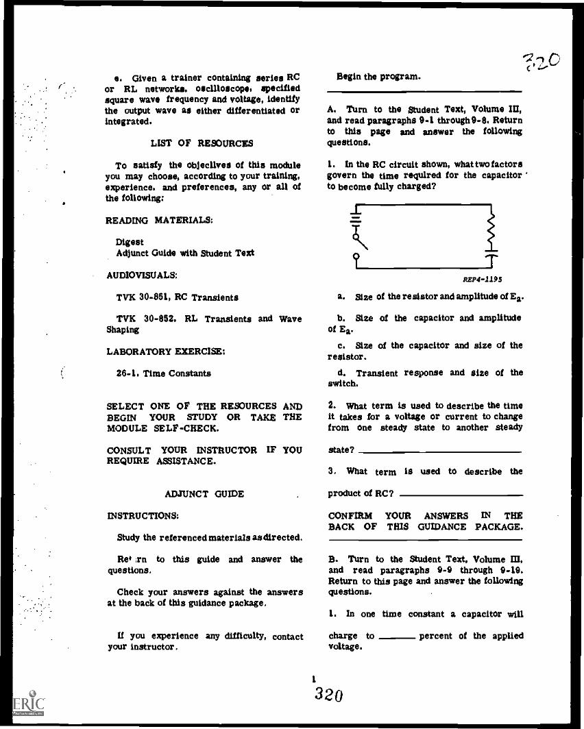
e. Given a trainer containing series RCor RL networks, oscilloscope, specifiedsquare wave frequency and voltage, identifythe output wave as either differentiated orintegrated.
LIST OF RESOURCES
To satisfy the objecilves of this moduleyou may choose, according to your training,experience, and preferences, any or all ofthe following:
READING MATERIALS:
DigestAdjunct Guide with Student Text
AUDIOVISUALS:
TVK 30-851, RC Transients
TVK 30-852, RL Transients and WaveShaping
LABORATORY EXERCISE:
26-1, Time Constants
SELECT ONE OF THE RESOURCES ANDBEGIN YOUR STUDY OR TAKE THEMODULE SELF-CHECK.
CONSULT YOUR INSTRUCTOR IF YOUREQUIRE ASSISTANCE.
ADJUNCT GUIDE
INSTRUCTIONS:
Study the referenced materials as directed.
Ref ,rn to this guide and answer thequestions.
Check your answers against the answersat the back of this guidance package.
If you experience any difficulty, contactyour instructor.
Begin the program.
A, Turn to the Student Text, Volume III,and read paragraphs 9-1 through 9-8. Returnto this page and answer the followingquestions.
1. In the RC circuit shown, what two factorsgovern the time required for the capacitorto become fully charged?
REPO -1195
a. size of the resistor and amplitude of Ea.
b. Size of the capacitor and amplitudeof Ea.
c. Size of the capacitor and size of theresistor.
d. Transient response and size of theswitch.
2. What term is used to describe the timeit takes for a voltage or current to changefrom one steady state to another steady
state?
3. What term
product of RC?
is used to describe the
CONFIRM YOUR ANSWERS IN THEBACK OF THIS GUIDANCE PACKAGE.
B. Turn to the Student Text, Volume ID,and read paragraphs 9-9 through 9-19.Return to this page and answer the followingquestions.
1. In one time constant a capacitor will
charge tovoltage.
1
320
percent of the applied

2. How many time constant* are needed fora capacitor to become fully charged?
a. Two
b. Three
c. Four
d. Five
3. What factor determines the rate of chargein an RC circuit?
a. The resistor
b. The applied voltage
c. The capacitor
4. How many time constants are needed fora capacitor to lose 98 percent of its originalcharge?
a. Two
b. Three
c. Four
d. Five
5. At the end of two time constants, thecapacitor in an RC circuit has discharged
percent. The charge remaining on the
capacitorcharge.
is percent of the initial
a. 86.3 13.7
b. 13.7 86.3
c. 86.3 86.3
d. 13.7 13.7
6. Alter 1.5 time constants, the voltageacross the resistor in an RC circuit has
decreased by percent.
321a. 22.5
b. 77.5
c. 25
d. 75
7. Using the Universal Time ConstantChart, determine the percent of Ea on thecapacitor at the end of the following timeconstants.
On Charge On Discharge
a. .3 TC
b. .9 TC
c. 1.2 TC
d. 2.4 TC
e. 3 TC
8. Using the Universal Time Constant Chartdetermine the number of time constantswhen the following percentages of the appliedvoltage are across the resistor during ca-pacitor charge.
a. 90 percent TC
b. 50 percent TC
c. 30 percent TC
d. 5 percent TC
e. 2 percent TC
CONFIRM YOUR ANSWERS IN THEBACK OF THIS GUIDANCE PACKAGE.
C. Turn to the Student Text, Volume III,and read paragraphs 9-20 through 9-33.Return to this page and answer the followingquestions.
2 321

1. Find the voltage across the capacitorand the resistor 10,000 microseconds afterthe switch is placed in position A.
EC *
ER =
I40V
REP4.4196
2. Reference the circuit in question one.U the capacitor was fully charged, what isthe voltage across the resistor, and thecurrent in the circuit, 15,000 microsecondsafter the switch is placed in position B.
ER
I=
3. Reference the circuit in question one.What is the number of time constants re-quired for EC to reach 18 volts after theswitch is placed in position A?
#TC =
4. A capacitor in an RC circuit is chargedto 100 volts and then starts to discharge.At the end of three time constants what isthe voltage across the capacitor and what isthe voltage across the resistor?
EC =
ER =
5. li C charges to 46.5 volts 570 micro-seconds after the switch is closed, R mustbe what value?
O. li C charges to 1.425 volts 2295 micro-seconds after the switch is closed, what isthe value of C?
C=
T1.5V
7. Eighty microseconds after the switchis closed, the current in the following cir-cuit will be what value?
I=
T°°"
OHO
8. In the following circuit, C has beencharged to 30 volts with the switch in posi-tion A. Eighty microseconds after the switchis thrown to position B, EC will be whatvalue? What will the circuit current be?
EC-
R= =
3
322

REP4 -1201
CONFIRM YOUR ANSWERS IN THEBACK OF THIS GUIDANCE PACKAGE.
D. Turn to the Student Text, Volume HI,and read paragraphs 9-34 through 9-45.Return to this page and answer the followingquestions.
1. In an RL circuit, what two factorscontrol the transient response of the circuit?
a. Inductance and voltage
b. Resistance and current
c. Voltage and current
d. Resistance and inductance
2. In an RI, circuit, what is the relationshipbetween time and inductance?
a. Directly proportional
b. Inversely proportional
3. On the Universal Time Constant Chartfor LR circuits, curve A shows what twothings on buildup?
a. ER and EL
b. EL and I
c. ER and I
4. After 1.8 time constants, inductor cur-
rent would have built up to percent ofits final value.
a. 20
c. 70
d. 80
5. After three time constants, inductor
current would have decayed by percent.What percent of the initial current would
still be flowing? ..... percent
a. 5 95
b. 25 75
c. 75 25
d. 95 5
CONFIRM YOUR ANSWERS IN THEBACK OF THIS GUIDANCE PACKAGE,
E. Turn to the Student Text, Volume III,and read paragraphs 9-48 through 9-53.Return to this page and answer the followingquestions.
1. Find the percent of current buildup andthe voltage across the coil after the switchhas been closed for 4000 microseconds.
percent of I ar
EL =
100V
I.20 H
R10 ha
REPO -1202
2. Using the circuit in problem one, solvefor the current flow at the end of 2000microseconds.
b. 30 I 4.
4
33
,

3. Solve for the voltage across the coil,and the circuit current, 1900 microsecondsafter the switch is closed.
EL
I=
REPO -1203
4. What will the current be 0.084 micro-second after the switch is closed?
1=
R SO k a
REPO -2204
5. Solve for current flow 200 microsecondsafter the switch is closed.
l =.
L 2H
R10 k a
REPO -2205
6. The switch is placed into position Auntil a field is completely built up aroundthe coil, then placed in position B. Thevoltage across the re sistor.600 microsecondsafter the switch is placed in position B willdecrease by what percent?
5
a. 23 percent
b. 99 percent
c. 61 percent
d. '77 percent
31+
R25 It a
L10 H
REP4*1209
7. Six microseconds after the switch isclosed the voltage across each resistor is28 volts. Solve for the value of L.
L
RI
2 k a100%,
I_
R22 k a
REPO -2207
8. The voltage across R is 36 volts 200microseconds after the switch is closed.What is the value of R?
R=
REP4 -1208
9. The switch is placed into position Auntil a field is completely built up aroundthe coil then placed in position B. What isthe voltage across the resistor 600 micro-seconds after the switch is placed in positionB?
324

ER
R25 k0
L10 H
REP4-1209
CONFIRM YOUR ANSWERS IN THEBACK OF THIS GUIDANCE PACKAGE.
F. Turn to the Student Text, Volume III,and read paragraphs 9-54 through 9-69.Return to this page and answer the followingquestions.
1. The output frequency of a symmetricalsquare wave generator is 5000 Hz. What isthe 4 i me of one alternation?
2. The time of one alternation of an unknownsymmetrical square wave is 90 micro-seconds. What is the frequency?
3. What determines whether a time constant
is long, medium, or short?
4. Identify the following waveforms for theresistor voltage and capacitor voltage in anRC circuit. Also specify whether it isa long,medium, or short time constant.
t=
,,O=,
time constant1,100V
INPUT
oV 616. 41M116616
......."----.......,........'"------. WAVE A
66666.6.,
WAVE B
----"..REP4-1210
6 3".i. 0
.6.%
I
1

1001/
ov
q 074ffiIP
/-__(--- __.
.._
5. Identify the waveforms shown above forthe resistor voltage and capacitor voltagein an RC circuit. Also identify whether itis a long, medium, or short time constant.
time constant
100V
ov
,...,111,
REP4-1211
...
INPUT
WAVL A
thAVL B
2.49
6. Identify the following waveforms for theresistor voltage and capacitor voltage in anRC circuit. Also identify whether it is along. medium, or short time constant.
7
326
INF. UT
time constant
hAVi B

100V
ov
.....==. IMO.M.
4
17. Identify the waveforms shown above forthe resistor voltage and the inductor voltagein an EL circuit. Also identify whether Itis a long, medium, or short time constant.
time constant
INPUT
WAVE A
WAVE B
32.7
8. Identify the following waveforms for theresistor voltage and inductdr voltage in anEL circuit. Also Identify whether it is along, medium, or short time constant.
100V IiIM.
INPUT
Ov 111111
...00.00.111.............................%..........WAVE A
Imm.. IMME.......,
WAVE B
....-'''...REP4-1210
8 27
time constant

100V
OV
,===m 01
/.....C...__
9. Identify the waveforms shown above forthe. resistor voltage and the inductor voltagein an RL Circuit. Also identify whether it isa long, medium, or short time constant.
time constant
CONFIRM YOUR ANSWERS IN THEBACK OF THIS GUIDANCE PACKAGE.
G. Turn to the Student Text, Volume m,and read paragraphs 9-70 through 9-92.Return to this page and answer the followingquestions.
1. Define a differentiation Circuit.
RSP4-1211
2. What portion of an RC or RL circuit isused to obtain a differentiated output? Also,indicate what type of time constant is used.
9
328
INPUT
WAVE A
WAVE a
3. Define an integrating circuit.
32$
4. What portion of an RC or Fa. circuit isused to obtain an integrated output? Also,indicate what type time constant is used.

CONFIRM YOUR ANSWERS IN THEBACK OF THIS GUIDANCE PACKAGE.
H. Turn to Laboratory Exercise 28-1 inwhich you will use the scope to identifyoutput waveforms of an RC or RL circuitas either integrated or differentiated.
YOU MAY STUDY ANOTHER RESOURCEOR TAKE THE MODULE SELF-CHECK.
LABORATORY EXERCISE 28-1
OBJECTIVES:
1. Given a circuit diagram. a trainer, andan input square wave of aspecitiedfrequencyand amplitude, connect the circuit on thetrainer.
2. Given an oscilloscope, identify the out-put waveform of an RC or an RL circuit aseither integrated or differentiated.
EQUIPMENT:
1. Oscilloscope, AN/US/8-3982. AC Inductor and Capacitor Trainer, 52173. Sine Square Wave Generator, 4884
REFERENCES:
1. Student Handout, KEP-1082. Student Text, Volume III, Chapter 9
CAUTION: OBSERVE BOTH PERSONNELAND EQUIPMENT SAFETY RULES ATALL TIMES. REMOVE WATCHES ANDRINGS.
PROCEDURES:
USM-398IntensityCH1CH2V/CMAC-GND-DCSep-CH1 & CH2AC -AC F-DCCHOP-ALTHor PosTime/CMTrig SelectLevel
Turn ONFully CCWMidOFF5
ACSepACALTMid.2 msCH1+AUTO
10
1. Connect this circuit.
1000 Hi10V11-9
A
0101.01uF
eR1031,21(11
C
RXP4-2602
2. Display on the oscilloscope three cyclesof the generator voltage. Keep the amplitudeat 2 cm (CH1 to point A and ground topoint C).
3. Draw this square wave input to thecircuit. Let TO to T2 be the time for onecycle.
INPUT
TO TI T2 T3 T4 TS T6
REPO -1215
4. Display the voltage waveform acrossR103 and draw ERlground to point C . Adjust amplitude to
3 (CH1 to point B andli
2 cm.
5. This waveform is:
a. Integrated.
b. Differentiated.
TO T1 T2 T3 T! TS T6
ER1O3
REP4-1226
8. Construct this circuit and display thecapacitor waveform on the scope. Drawthe waveform for C101 (CH1 to point Band ground to point C). Adjust amplitudeto 2 cm.
3.21

100014
10y
CONFIRM YOUR ANSWERS IN THER104 BACK OF THIS GUIDANCE PACKAGE.
5.11111
RIP44607
7. This waveform is:
a. Differentiated.
b. Integrated.
RU42227
8. Replace C101 with coil L101.
CONSULT YOUR INSTRUCTOR FOR THEPROGRESS CHECK.
YOU MAY STUDY ANOTHER RESOURCEOR TAKE THE MODULE SELF - CHECK.
MODULE SELF -CHECK
1. Solve for percent of charge, EC, ER,and I, 25 microseconds after the switch isclosed.
percent of charge
BC'
ER
=
R104
-I-
A
S Mu
10Vo-o
1000
I. OT
][7"
Hi a
100 4114
RSO k
"001 uF
Jai:4-1220
REPO -2603 2. Solve for percent of charge, EC, ER,and I, 1200 microseconds after switch is
9. Display EL101 on the scope. Set ampli- closed to point A.tude to 2 cm and draw the waveform EL101(CH1 to point B and ground to point C). percent of charge =
EC10. This waveform is:
a. Differentiated.
b. Integrated.
TO
4,102
T1 T2 T3 T4 TS T6w w
MMI MmOm MM
MOORES...I MMOO MM
REPO -1218
11
330
ER =
-
A
1130V
R20 kg
02 uF
;641721

3. Using the circuit in problem 2, the 8. Solve for EL, ER, and 1, 400 micro.capacitor has charged to 180 volts. What is seconds after the switch is closed.percent of discharge, percent of chargeremaining, Ec, ER, and 1, 800 microsecondsafter the switch is placed in position 8?
percent of discharge *
percent remaining a
EC -ER
I=
4. Solve for percent of current buildup,EL, ER, and I, 200 microseconds after theswitch is closed. 200V
percent of buildup a
EL = -ER aI=
EL
50VI
0
110 Of
100 0
REP4-1222
5. The switch is placed in position A untilthe field is completely built up. Solve forpercent of current decay and current, 1200microseconds after the switch is placed inposition B.
percent of decay a
current -
4=0
Q0 H
25 k 0
REP4-1223
12
4HH
20 k 0
REP4-1224
7. Identify the following circuit as havinga long, medium, or short time constant.Label the waveforms as ER or EC.
time constant
*".°',,./'WAVEFORM A
%" f"., r...
WAVEFORM B .......- ......--- 1......'
..)"31
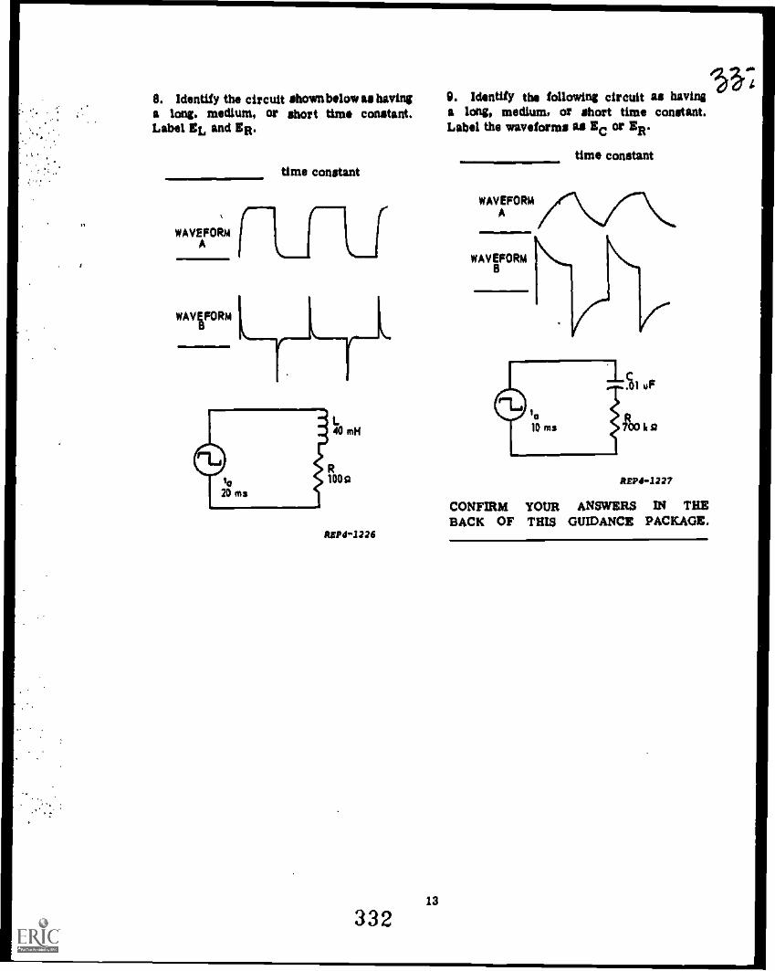
11
8. Identify the circuit shownbelow as havinga long, medium, or short time constant.Label EL and ER.
WAVEFORMA
WAVEFORMB
time constant
REPO -1226
33213
$...L0. Identify the following circuit as havinga long, medium, or short time constant.Label the waveforms as EC or ER.
WAVEFORMA
WAVEFORMB
time constant
REPI -1227
CONFIRM YOUR ANSWERS IN THEBACK OF THIS GUIDANCE PACKAGE.

ANSWERS TO A:
1. c
2. Transient interval
3. A time constant
If you missed ANY questions, review thematerial before you continue.
ANSWERS TO B:
1. 03 percent
2. d
3. b
4. c
5. a
6. b
7. a. 27 percent, 73 percentb. 60 percent, 40 percentc. 70 percent, 30 percentd. 91 percent, 9 percente. 95 percent, 5 percent
8. a. 0.1 TCb. 0.7 TCc. 1.2 TCd. 3 TCe. 4 TC
If you missed ANY questions, review thematerial before you continue.
ANSWERS TO C:
1. EC = 34.52VER = 5.48V
2. ER = 2 volts, I = 20 microarnps
3. OTC = 0.6 TC
4. Ec = 5V, ER = 5V
14
5, R 3800 ohms
0. C 7050 picofarads
7, 1 1.6 mA
8. Ec a 20.1V I 1 mA
If you missed ANY answers, review thereferenced material before you continue.
ANSWERS TO D:
1. d
2. a
3. c
4. d
5. d
If you missed ANY answers, review thereferenced material before you continue.
ANSWERS TO E:
1. percent of I = 88 percentEL = 14 volts
2. I = 6.3 mA
3. EL = 20 voltsI = 1 mA
4. 0.225 mA
5. I = 0.3 mA
a. d
7. L = 30 rail
8. R = 900 ohms
9. ER = 40 volts
If you missed ANY questions, review thereferenced material before you continue.
333

ANSWERS TO F:
1. 100 microseconds
2. 12.5 kHz
3. The time allowed or the time to whichthe time constant is being compared.
4. Long time constant; wave A si EC;wave B = ER
5. Medium time constant; wave A = EC;wave B = ER
6. Short time constant; wave A = ER;wave B = EC
7. Short time constant; wave A = EL;wave B = ER 1. percent of charge = 40 percent
EC = 200V8. Long time constant; wave A = ER; ER = 300Vwave B = EL I = 6 na
ANSWERS TO LAB EXERCISE:
5. b
7. b
10. a
If you missed ANY questions, review thereference material before you continue.
ANSWERS TO MODULE SELF-CHECK:
9. Medium time constant; wave A = ER;wave B = EL
If you missed ANY questions, review thereferenced material before you continue.
ANSWERS TO G:
1. Differentiating circuits produce an out-put voltage proportional to the rate of changeof the input.
2. A short time constant is used and theoutput is taken across the resistor in an RCcircuit or the inductor in an RL circuit.
3. An integrating circuit produces an out-put voltage that is proportional to the areaunder the input waveform.
4. A long time constant is used and theoutput is taken across the capacitor in anRC circuit and across the resistor in anRL circuit.
U you missed ANY questions. review thereferenced material before you continue.
33415
2. percent of charge lit 95 percentEC =171VER = 9VI = 0.45 mA
3. percent of discharge = 86 percintpercent remaining = 14 perceraEC = 25.2VER = 25.2VI= 1.26 mA
4, percent of I buildup = 86 percentEL =7VER = 43VI = 0.43A
5. percent of I decay = 25 percentI = 3 mA
6. EL = 26VER = Ifi2VI = 8.6 mA
7. Long time constantEC waveform AER waveform B
8. Short Urn. constantER waveform'AEL waveform B
9. Medium time constantEC waveform AER waveform B
18
HAVE YOU ANSWERED ALL OF THEQUESTIONS CORRECTLY? IF NOT,REVIEW THE MATERIAL OR STUDYANOTHER RESOURCE UNTIL YOU CANANSWER ALL QUESTIONS CORRECTLY.IF YOU HAVE, CONSULT YOUR IN-STRUCTOR FOR FURTHER GUIDANCE.
335

§A)ATC GP 3A0R3X020-X
prepared by Kessler TTCKEP-GP-27
Technical Training
ELECTRONIC PRINCIPLES (MODULAR SELF-PACED)
MODULE 27
FILTERS
ATC Kettslr 1-4411
April 1976
4
AIR TRAINING COMMAND
"7-17
Designed For Alt Cows* Us.
DO NOT US! ON THE JOS
336
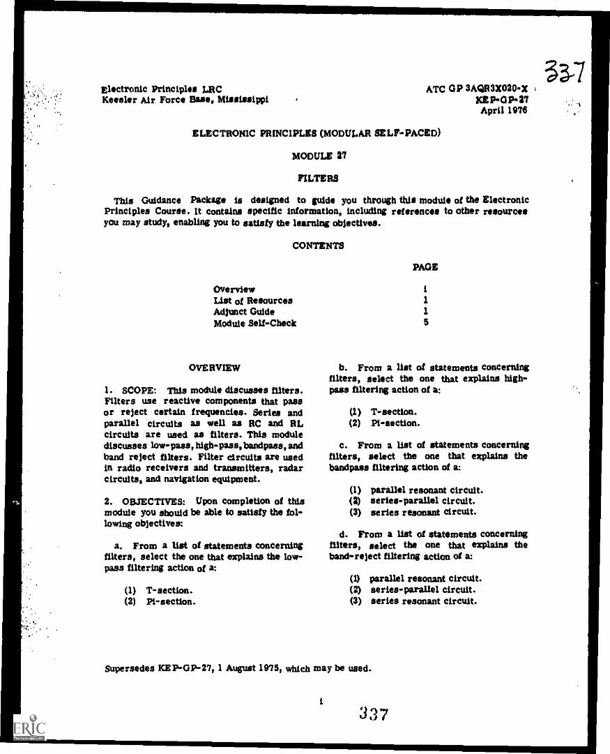
33-7Electronic Principles MC ATC GP 3AQR3X020-XKees ler Air Force Base, Mississippi KEPCIP-27
April 1074
ELECTRONIC PRINCIPLES (MODULAR SELF-PACED)
MODULE 27
FILTERS
This Guidance Package is designed to guide you through this module of the ElectronicPrinciples Course. It contains specific information, including references to other resourcesyou may study, enabling you to satisfy the learning objectives.
CONTENTS
OverviewList of ResourcesAdjunct GuideModule Self -Check
OVERVIEW
1. SCOPE: This module discusses filters.Filters use reactive components that passor reject certain frequencies. Series andparallel circuits as well as RC and RLcircuits are used as filters. This modulediscusses low-pass, high-pass, bandpass, andband reject filters. Filter circuits are usedin radio receivers and transmitters, radarcircuits, and navigation equipment.
2. OBJECTIVES: Upon completion of thismodule you should be able to satisfy the fol-lowing objectives:
a. From a list of statements concerningfilters, select the one that explains the low-pass filtering action of a:
(1) T-section.(2) Pi-section.
PAGE
i1
1
5
b. From a list of statements concerningfilters, select the one that explains high-pass filtering action of a:
(1) T-section.(2) Pi-section.
c. From a list of statements concerningfilters, select the one that explains thebandpass filtering action of a:
(1) parallel resonant circuit.(a) series-parallel circuit.(3) series resonant circuit.
d. From a list of statements concerningfilters, select the one that explains theband-reject filtering action of a:
(1) parallel resonant circuit.(2) series-parallel circuit.(3) series resonant circuit.
Supersedes ICEP- GP-27, 1 August 1975, winch may be used.
i337

f
LIST OF RESOURCES 1. Define filter:
To satisfy the objectives of this module,you may choose, according to your training,experience, and preferences, any or all ofthe following:
READING MATERIALS:
DigestAdjunct Guide with Student Text
2. What impedance does acapacitor presentAUDIO-VISUALS: to high frequencies? Low frequencies?
Television Lesson, Filters (A), TVK 30-305Television Lesson, Filters (B), TVK30 -306
At this point, if you feel that throughprevious experience or training you arefamiliar with this subject, you may takethe Module Self-Check. If not, select oneof the resources and begin study.
pi)
CONSULT YOUR INSTRUCTOR IF YOU 3. What impedances does an inductor presentREQUIRE ASSISTANCE. to high frequencies? Low frequencies?
ADJUNCT GUIDE
INSTRUCTIONS:
Study the referenced materials as directed.
Return to this guide and answer thequestions.
Confirm your answers at the back of thisGuidance Package.
If you experience any difficulty, contactyour instructor.
Begin the program.
A. Turn to Student Text Volume III and readparagraphs 10-1 through 10-9. Return tothis page and answer the followingquestions.
4. Identify the following circuits as being aHigh Pass Filter, Low Pass .Filter, BandPass Filter, or Band Reject Filter.
a.
1
338

4. b. 2. Draw a circuit diagram, using coils andCapacitors, for a pi -type low-pass filter.
c
d.
0-11Y114
I
ri iREPO -11J6
CONFIRM YOUR ANSWERS
B. Turn to Student Text Volume M andread paragraphs 10-10 through10-22.Returnto this page and answer the followingquestions.
1. Which of the following is a low-pass filter?
a. T section with series C and shunt L.
b. T section with shunt C and series L.
c. L section with series C and shunt L.
._. d. L section with shunt L and series R.
2
3. T and Pi- section low-pus filters usewhich of the following:
. .. a. Series capacitors and shunt coils.
--. b. Series coils and shunt capacitors.
c. Series resistors and shunt coils.
d. Series capacitors and shuntresistors.
CONFIRM YOUR ANSWERS
C. Turn to Student Text Volume III andread paragraphs 10-23 through 10-29. Returnto this page and answer the followingquestions.
I. Draw a circuit diagram, using coils andcapacitors, for a T-section high-pass filter.
339
33-q
)
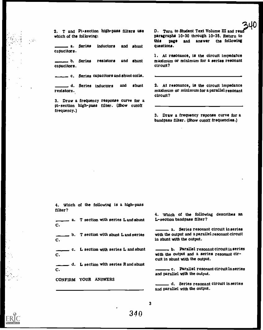
2. T and Pi-section high-pus filters usewhich of the following:
a. Series inductors and shuntcapacitors.
-. b. Series resistors and shuntcapacitors.
Series capacitors and shunt coils.
d. Series inductors and shuntresistors.
3. Draw a frequency response curve for api-section high-pass filter. (Show cutofffrequency.)
4. Which of the following is a high-passfilter?
-. a. T section with series L and shuntC.
- b. T section with shunt L and seriesC.
- c. L. section with series L. and shuntC.
C.d. L section with series R and shunt
CONFIRM YOUR ANSWERS
3
340
D. Turn to Student Text Volume III and re?paragraphs 10-30 through 10-35. Return tothis page and answer the followingquestions.
1. At resonance, is the circuit impedancemaximum or minimum for a series resonantcircuit?
2. At resonance, is the circuit impedancemaximum or minimum for a parallel resonantcircuit?
3. Draw a frequency reponse curve for abandpass filter. (Show cutoff frequencies.)
..
4. \which of the following describes anL-section bandpass filter?
a. Series resonant circuit in serieswith the output and a parallel resonant circuitin shunt with the output.
b. Parallel resonant circuit in serieswith the output and a series resonant cir-cuit in shunt with the output.
- c. Parallel resonant circuit ln seriesand parallel with the output.
d. Series resonant circuit in seriesand parallel with the output.
Lio

5. An L-section resonant filter is used topass a range of frequencies from 20 kHzto 30 kHz with a resonant frequency of25 kHz. To what frequency is the seriesresonant circuit tuned and to what frequencyis the parallel resonant tank tuned?
a. Series resonant circuit
b. Parallel resonant circuit
6. What is the main advantage of the Tand pi-type resonant filters over the Lsection resonant filter?
CONFIRM YOUR ANSWERS.
E. Turn to Student Text Volume III andread paragraphs 10-36 through 10-39. Returnto this page and answer the followingquestions:
I. Draw the frequency response curve for aband-reject filter. (Show cutoff frequencies.)
2. 'Which of the following describes an Lesection band-reject filter?
--, a. Series resonant circuit in serieswith the output and a parallel resonant cir-cuit in shunt with the output.
--.. b. Parallel resonant circuit in serieswith the output and a series resonant circuitin shunt with the output.
- c. Parallel resonant circuit in seriesand parallel with the output.
d. Series resonant circuit in seriesand parallel with the output.
3. What purpose does the parallel resonanttank serve in the Pl-type band-reject filter?
4. Recalling the characteristics of resonantcircuits, what factor would govern the band-width of any type bandpass or band-rejectfilter?
II.
CONFIRM YOUR ANSWERS

1
MODULE SELF-CHECK
Questions:
1. Identify the filter shown.
a. T-section low - pass
- b. T-section high-pass
c. Pi-section low-pass
d. Pi-section high-pass
0 iarrill ir'l.nO
ct o
2. identify the filter shown.
a. T-section band-reject
b. T-section bandpass
c. Pi-section band-reject
Pi-section bandpass
3425
3. Identify the filter shown.
a.
b.
c.
d.
T-section loyspass
T-section high-pass
Pi- section low-pass
Pi-section high-pass
4. Identify the filter shown.
a.
b.
c.
d.
T-section low-pass
T-section high-pass
Pi-section low-pass
Pi-section high-pans
3L11

6. Identify the filter shown. 7. Which of the following are true (T) orfalse (F)?
..__..... T..section band-reject
T-section bandpass
Pi-section band-reject
Pi-section bandpass
6. Identify the filter shown.
a. T-section low-pass
-. b. T-section high -pass
c. Pi-section low-pus
d. Pi-section high-pass
0.IIPrrrrnerp
o- 0
6
.---.. a. A T-section low-pass filter can bemade into a highPass filter by reversing theinput and output connections.
b. High-pass filters have capacitorsin series with the output while low-pass filtershave capacitors in parallel with the output.
.----. c. High pass filters have inductorsin parallel with the output while low-passfilters have inductors in series with theoutput.- d. A Pi-section band-reject filterhas a series resonant circuit in serieswith the mdput and two parallel resonantcircuits in parallel with the output.
,- e. A T-section bandpass filter hastwo series resonant circuits in series withthe output and a parallel resonant circuitin parallel with the output.
CONFIRM YOUR ANSWERS
3.4 3

ANSWERS TO A ADJUNCT GUIDE
1. A filter is a number of impedancesgrouped together which are designedto pass a certain range of frequenciesand to block another range of frequencies.
2. A capacitor presents very littleopposition to high frequencies (ashort) and a great deal of opposi-tion to low frequencies (an open).
3. A coil or inductor presents a greatdeal of opposition to high frequencies(an open) and very little oppositionto low frequencies (a short).
4. a. High pass filterb. Low pass filterc. Bandpass filterd. Band reject filter
If you missed ANY questions, review thematerial before you continue.
ANSWERS TO B - ADJUNCT GUIDE
1. b
2.
11151111111.iinn.nMI11101110Me
0. 0
3. B
If you missed ANY questions, reviewthe material before you continue.
i344
ANSWERS TO C - ADJUNCT GUIDE
1.
2.
3.
c
4. b
If you missed ANY questions, review thematerial before you continue.
ANSWERS TO D - ADJUNCT GUIDE
1. Minimum2. Maximum
3.
I
I
I I
I I
I I
I I
fci 1c2
4. a
5. Series resonant circuit 25 kHzParallel resonant circuit 25 kHz

A
0. T and pi types offer equal impedeance when looking into the filterfrom input or output terminals.(Symmetrical filter)
U you missed ANY questions, review thematerial before you continue.
ANSWERS TO E ADJUNCT GUIDE
I.
I
1
1
I
. b
1
1
1
iI I
tcl
FREQUENCY
fc2
3. Otters maximum opposition to theresonant frequency.
4. The Q of the circuit.
U you missed ANY questions, reviewthe material before you continue.
8
ANSWERS TO MODULE SELFCHECK:
I. a
2. c
3. b
4. d
5. b
IL c
la. F
b. T
c. T
d. F
e. T
HAVE YOU ANSWERED ALL OF THEQUESTIONS CORRECTLY? IF NOT,' REVIEWTHE MATERIAL OR STUDY ANOTHERRESOURCE UNTIL YOU CAN ANSWERALL QUESTIONS CORRECTLY. IF YOUHAVE, CONSULT YOUR INSTRUCTORFOR FURTHER GUIDANCE.
v47

ATC GP 3ACIR3X020-XPrepared by Kessler TTC
KEP-GP-28
Technical Training
Electronic Principles (Modular Self-Paced)
Module 28
COUPLING
An !Wolin' 0-3444
15 July 1975
4 * **Ilpfir4* *4 ** 4
AIR TRAINING COMMAND
7-7Designed For ATC Coors. Use
DO HOT USE OH THE JOE
3.

C-E Officer & Space Surveillance Department Guidance Package 3AQR3X020X 3(1 1Koester Air Force Base, Mississippi KEP-OP-28
15 July 1075
ELECTRONIC PRINCIPLES (MODULAR SELF-PACED)
MODULE 28
COUPLING
This Guidance Package is designed, to guide you through this module of the ElectronicPrinciples Course. It contains specific information, including references to other resourcesyou may study, enabling you to satisfy the learning objectives.
CONTENTS
Title Page
OverviewList of ResourcesAdjunct GuideModule Self-Check
ii1
2
'J
COUPLING
1. SCOPE: In electronic circuits it isnecessary to pass signals from one circuitto another. To pass a signal, the two cir-cuits must be coupled together. Co Upliftsmay be direct, inductive, or capacitive.This module will discuss direct coupling,RC coupling, LC coupling, and transformercoupling.
2. OBJECTIVES: Upon completion of thismodule you should be able to satisfy thefollowing objectives:
a. Given circuit diagrams and a list ofstatements, select the statement(s) that ex-plain(s) the operation of
(1)(2)(3)(4)
direct coupling.RC coupling.LC coupling.transformer coupling.
b. From a list of statements, select theone(s) that describe(s) the types of couplingthat will provide
Supersedes KEP-GP-28, 1 July 1074. Previous
(1) impedance matching.(2) desired frequency response.(3) signal gain.
LIST OF RESOURCES
To satisfy the objectives of this module,you may choose, according to your training,experience, and preferences, any or all ofthe following:
READING MATERIALS:
DigestAdjunct Guide with Student Text
At this point, if you feel that throughprevious experience or training you arefamiliar with this subject, you may take theModule Self-Check. If not, select one of theresources and begin study.
CONSULT YOUR INSTRUCTOR IF YOUREQUIRE ASSISTANCE.
editions may be used.
i
347
?
1

.
1 : ...
ADJUNCT GUIDE
INSTRUCTIONS:
Study the referenced materials as directed.
Return to this guide and answer thequestions.
Check your answers against the answersin the back of this guide.
If you experience any difficulty, contactyour instructor.
Begin the program.
A. Turn to Student Text Volume III andread paragraphs 11-1 through 11-6. Returnto this page and answer the followingquestions.
I. Coupling is defined as a means by which
a. voltage measurements of one cir-cuit are compared to another circuit.
b. signals are transferred from onecircuit to another.
-. c. signals are attenuated or, eli-minated from the output circuit.
--. d. reactances are transferred fromone circuit to another circuit.
2. Direct coupling is a means of using
-. a. a capacitor to provide a path forsignal currents.
-- b. a transformer to provide a pathfor signal currents.
c. an inductor to provide a path firsignal currents.
d. a resistor or conductor to pro?vide a path for signal currents.
1
348
3. When using direct coupling
...-...- a. the input signal will experiencea phase shift in the output of the couplingcircuit.
b. DC voltages are eliminated in theoutput of the coupling circuit.
c. an exact reproduction of the inputsignal will be provided to the output of thecoupling circuit,
cl, operation will be limited due tothe narrow frequency range of the circuit.
CONFIRM YOUR ANSWERS IN THE BACKOF THIS GUIDE.
B. Turn to Student Text Volume III andread paragraphs 11-7 through 11-15. Returnto this page and answer the followingquestions.
1. The capacitor in an RC coupling circuitblocks
a. the AC component and passes theDC component.
..-__ b. the DC component and passes theAC component.
- c. both the AC and DC components.
2. Is the following statement true (T) orfalse (F)?
-. The output signal from an RC couplingcircut is taken across the resistor.
3. The AC component to be used in theoutput of an RC coupling circuit is developedby the
a. charging and discharging currentof the capacitor through the resistor.
- b. ratio of XC to R over the selectedfrequency range.
c. working voltage rating of thecapacitor.
34'6
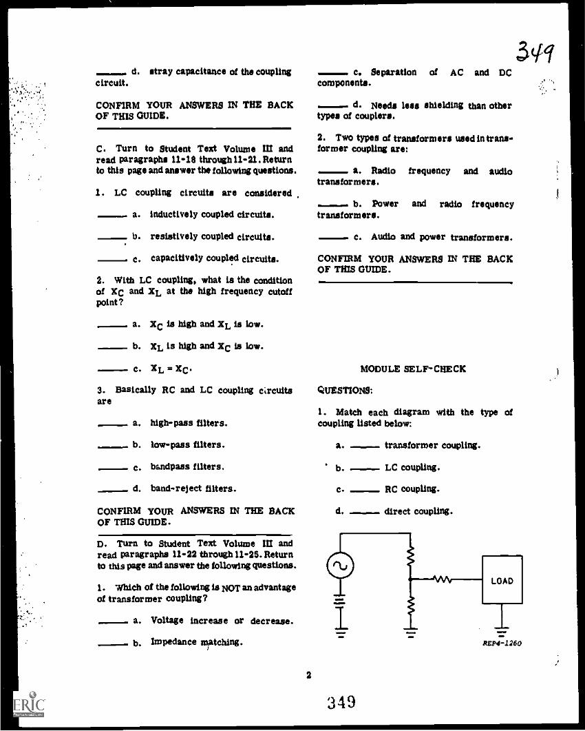
-. d. stray capacitance of the couplingcircuit.
CONFIRM YOUR ANSWERS IN THE BACKOF THIS GUIDE.
C. Turn to Student Text Volume III andread paragraphs 11-16 through 11 -21. Returnto this page and answer the following questions.
1. LC coupling circuits are considered
- a inductively coupled circuits.
b. resistively coupled circuits.
c. capacitively coupled circuits.
2. With LC coupling, what is the conditionof XC and XL at the high frequency cutoffpoint?
- a. Xc is high and XL is low.
b. XL is high and Xc is low.
-- c. XL =Xc.3. Basically RC and LC coupling circuitsare
- a. high-pass filters.
- b. low-pass filters.
c. bandpass filters.
d. band-reject filters.
CONFIRM YOUR ANSWERS IN THE BACKOF THIS GUIDE.
D. Turn to Student Text Volume III andread paragraphs 11-22 through11-25. Returnto this page and answer the following questions.
1. Which of the following IS NOT an advantageof transformer coupling?
, _ a. Voltage increase or decrease.
b. Impedance matching.
c. Separation of AC and DCcomponents.
-... d. Needs less shielding than othertypes of couplers.
2. Two types of transformers used in trans-former coupling are:
a. Radio frequency and audiotransformers.
-.. b. Power and radio frequencytransformers.
c. Audio and power transformers.
CONFIRM YOUR ANSWERS IN THE BACKOF THIS GUIDE.
MODULE SELF-CHECK
QUESTIONS:
1. Match each diagram with the type ofcoupling listed below:
a. - transformer coupling.
b.
C.
d.
- LC coupling.
RC coupling.
- direct coupling.
3(11
2
349
REPO -1260

';'. ., : * .
II
B
ASP4 -1261
REPO-1262
C
D
2. Match each response curve with the typeof coupling listed below:
a. Transformer Coupling
b. -. LC Coupling
c. RC Coupling
d. Direct Coupling
350
3
tg
A
iFREQUENCY
B
FREQUENCY
C
Om
11.
FREQUENCY
D
'W)
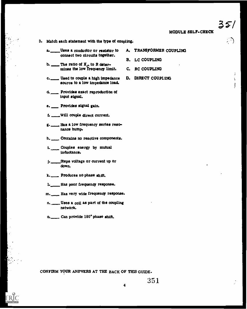
3. Match each statement with the type of coupling.
a. Uses a conductor or resistor toconnect two circuits together.
b. The ratio of X,.. to R deter-mines the low Trequency limit.
Used to couple a high impedancesource to a low impedance load.
d. Provides exact reproduction ofinput signal.
e. Provides signal gain.
1. Will couple direct current.
g._ Has a low frequency series reso-nance hump.
b. Contains no reactive components.
L Couples energy by mutualinductance.
J. Steps voltage or current up ordown.
k. Produces no phase shift.
I. Has poor frequency response.
m. Has very wide frequency response.
n., Uses a coil as part of the couplingnetwork.
o. Can provide 1800 phase shift.
MODULE SELFCHICCE
A. TRANSFORMER COUPLING
B. LC COUPLING
C. RC COUPLING
D. DIRECT COUPLING
CONFIRM YOUR ANSWERS AT THE BACK OF THIS GUIDE.
431lJ
3s/
i
1

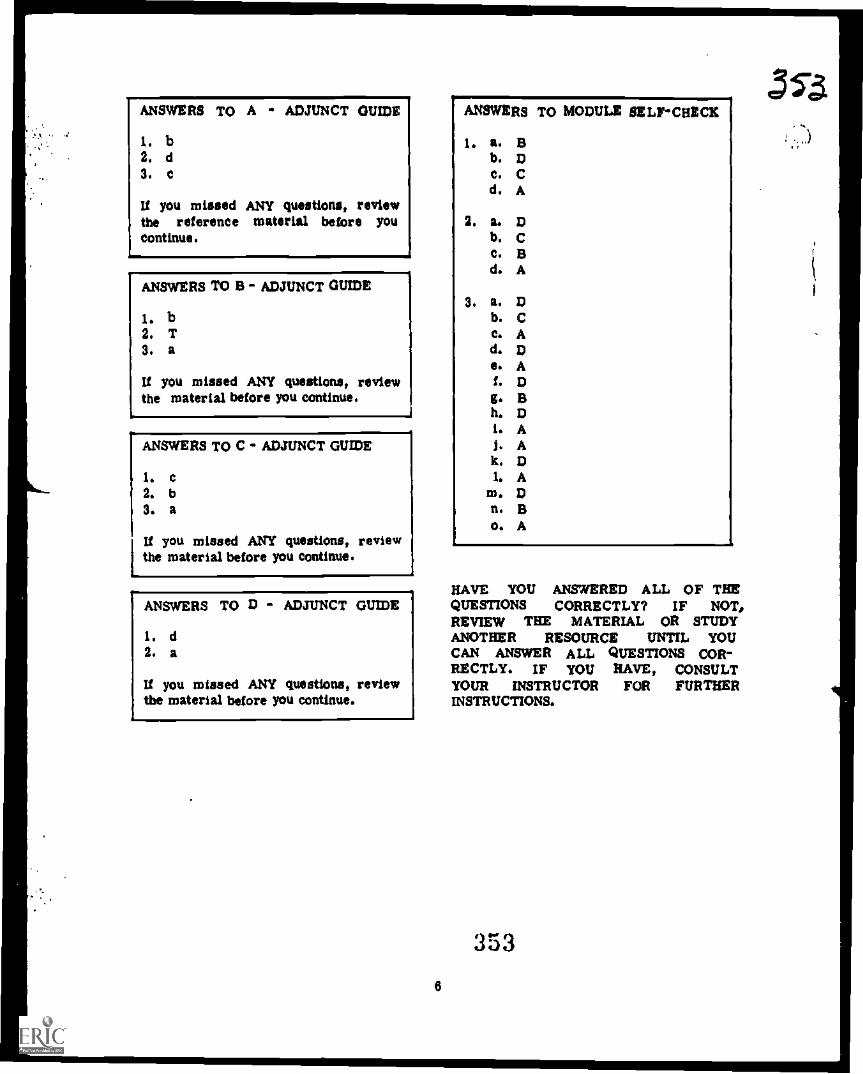
ANSWERS TO A ADJUNCT GUIDE
I. b2. d3. c
If you missed ANY questions, reviewthe reference material before youcontinue.
ANSWERS TO B - ADJUNCT GUIDE
I. b2. T3. a
If you missed ANY questions, reviewthe material before you continue.
ANSWERS TO C - ADJUNCT GUIDE
I. c2. b3. a
If you missed ANY questions, reviewthe material before you continue.
ANSWERS TO D - ADJUNCT GUIDE
I. d2. a
If you missed ANY questions, reviewthe material before you continue.
.
8
ANSWERS TO MODULE SELFCHECK
I. a. ab. 0c. Cd. A
2. a. to
b. Cc. Bd. A
3. a. Db. Cc. Ad. 0e. Af. Dg. Bh. Di. AJ. Ak. DL A
In. Dn. Bo. A
HAVE YOU ANSWERED ALL OF THEQUESTIONS CORRECTLY? IF NOT,REVIEW THE MATERIAL OR STUDYANOTHER RESOURCE UNTIL YOUCAN ANSWER ALL QUESTIONS COR-RECTLY. IF YOU HAVE, CONSULTYOUR INSTRUCTOR FOR FURTHERINSTRUCTIONS.
353
(1