Document Name: CIMR-E7Z8801-SPED007 … - PUMP SEQUENCER.pdf · 4 PUMP SEQUENCER PARAMETER LIST ......
22
Only constitutes a controlled document if stamped in red ink “Controlled Copy” MAC Center Distribution: PREPARED BY: CHECKED BY: APPROVED BY: MAC MAC/ADDC MAC/ADDC CIMR-E7Z CASE development CAS specifications Template CIMR-E7Z8801-SPED007-PUMPSEQStep2 050912 4 September 2006 CASE CUSTOMIZED APPLICATION SOFTWARE DEVELOPMENT QUALITY DOCUMENT Document Name: CIMR-E7Z8801-SPED007-PUMPSEQStep2 SPER=Request, SPED=Development CIMR-E7Z CAS SPECIFICATIONS REQUEST/DEVELOPMENT ISSUE 1.0 DRAFT I Revision 1
Transcript of Document Name: CIMR-E7Z8801-SPED007 … - PUMP SEQUENCER.pdf · 4 PUMP SEQUENCER PARAMETER LIST ......

Only constitutes a controlled document if stamped in red ink “Controlled Copy” �
MAC Center
Distribution:
PREPARED BY: CHECKED BY: APPROVED BY:
MAC MAC/ADDC MAC/ADDC
CIMR-E7Z CASE development CAS specifications Template CIMR-E7Z8801-SPED007-PUMPSEQStep2 050912
4 September 2006
CASE
CUSTOMIZED APPLICATION SOFTWARE DEVELOPMENT
QUALITY DOCUMENT
Document Name:
CIMR-E7Z8801-SPED007-PUMPSEQStep2
SPER=Request, SPED=Development
CIMR-E7Z CAS SPECIFICATIONS REQUEST/DEVELOPMENT
ISSUE 1.0 DRAFT I
Revision 1

CIMR-E7Z8801-SPED007-PUMPSEQStep2 050912 Page 2 of 22 Issue 1.0 Draft I
Template Document History
Issue: Date: Author: Changes and additions:
1 Draft A 30 October 2003 Cándido Ferrio First Draft release 1 Draft A 6 November 2003 Cándido Ferrio Change in specs related with max
auxiliary pumps possible ! 1 Draft B 12 December 2003 Cándido Ferrio Parameter list fixed 1 Draft D 9 June 2004 Cándido Ferrio New tentative parameter organization 1 Draft E 23 June 2004 Cándido Ferrio Parameter units and texts done. 1 Draft F 1 April 2005 Cándido Ferrio E7IP54 support + 4 aux pumps 1 Draft G 8 August 2005 Cándido Ferrio Updated graphics 1 Draft H 6 Sept 2005 Cándido Ferrio Corrected mistake in units handling 1 Draft I 12 Sept 2005 Cándido Ferrio Documentation defaults changed to
correct values.
In the event of errors or omissions, please notify: CFD
Comments required by:
Next update of this document:

CIMR-E7Z8801-SPED007-PUMPSEQStep2 050912 Page 3 of 22 Issue 1.0 Draft I
CONTENTS
1 REQUEST : MARKETING DATA ........................... .....................................4
2 REQUEST : TECHNICAL DESCRIPTION.................... ...............................5
3 OPERATION DIAGRAMS................................. ...........................................8
4 PUMP SEQUENCER PARAMETER LIST ...................... .............................9
4.1 General scope ...................................................................................9
4.2 Additional parameters........................................................................9
4.2.1 Parameter group (Max 4)..................................................9
4.2.2 Additional CASE Application parameters (máx 30).........10
4.2.3 Additional digital Input (Max 8) .......................................14
4.2.4 Additional digital output (Max 3) .....................................15
4.2.5 Additional Monitor / Analog Output (Max 10) ..................15
4.2.6 Modified Analog Output settings.....................................16
4.2.7 Additional Fault (Max 5)..................................................16
4.2.8 Additional Alarm (Max 5) ................................................17
4.2.9 Additional OPE (only 1) ..................................................18
4.2.10 New Defaults for std params and relevant param...........18

CIMR-E7Z8801-SPED007-PUMPSEQStep2 050912 Page 4 of 22 Issue 1.0 Draft I
1 REQUEST : MARKETING DATA
NSC All
Issued by (Responsible) Cándido Ferrio
Issued Date 8-Aug-2005
Customer Name many
Market (Textile, Paper, etc…) many
Application/Solution (Winding, Hoisting, etc) Fluid supply control
Related Function (KEB, etc…) PID, sequencing, etc...
Product Type CIMR-E7Z CIMR-E7Z IP54
Number of Drives -
Potential Sales (in Euro)
Competitors Danfoss, ABB, VACON, CT, SIEMENS, others
Competitor Model
Danfoss VLT6000HVAC, ABB ACS600, VACON CX / NX, CT Unidrive V3, SIEMENS Micromaster 430, Delta, TOSHIBA
Request Completion Date Release of E7Z high IP rating

CIMR-E7Z8801-SPED007-PUMPSEQStep2 050912 Page 5 of 22 Issue 1.0 Draft I
2 REQUEST : TECHNICAL DESCRIPTION
Introduction : Traditionally, pump systems when reaching certain capacity require splitting the pump unit of big capacity into smaller ones. Then it is a simple way to keep pressure in the circuit within certain limits in Steps just starting and stopping this pumps, thus saving energy as the flow demand variation is big and not all the pumps are required all the time ... With the introduction of Variable Speed Drives the technology allowed continuous and smooth control through closed loop pressure sensor PID control loop. This provided the best circuit response and implemented means of reducing the stress in the piping system when pumps were directly started. Current problem / solution: When it comes to big capacity pumping, using a unique big pump and inverter for smooth control becomes too expensive solution... Then a hybrid solution of a modulated pump + several auxiliary fixed speed pumps with intelligent sequencing controller was found to be an optimal solution... Description of the requirement:

CIMR-E7Z8801-SPED007-PUMPSEQStep2 050912 Page 6 of 22 Issue 1.0 Draft I
Pump sequencer software provides within the inverter logic functionalities to control a system of pumps where one pump is being controlled in speed and others are started and stopped by system pressure demand and conditions... The pressure in the system is closed-loop controlled by an advanced PID controller also integrated in the inverter. The herewith presented firmware implements both PID regulation, multiple configurable slave pumps handling, advanced monitoring and alarming conditions, pressure units, etc... to provide a compact and flexible solution for pump control systems. The software described in this document allows the control of a system of up to 5 pumps. When E7Z implements this firmware we have following pump-oriented functionality :
• ALL IN ONE : Inverter houses all control .. • CONTROL MODES : Pressure (Pump, compressor, fan, inverse vacuum control), Flow
(Square Root model of pressure) temperature and Level Control • PHYSICAL UNITS : Setpoint and Present Value readout in pressure, level or % units : bar,
Kg/cm, psi (lb/in2), m (in level mode), l/s, m3/h, gallon/min (in flow mode), % • FEEDBACK SIGNAL SIMULATION : by parameter for PID simulations without sensor… • MODULATED PUMP CONTROL :
o Starting and Stopping configurable conditions from feedback pressure reading, output frequency and auxiliary pump status...
o Minimum, maximum speed for controlled pump modeling o Advanced PI control.
• AUXILIARY PUMPS CONTROL : o Definable amount and control of auxiliary pumps up to 2 without additional hardware.
4 auxiliary pumps with up to 2 additional OMRON relays : K8AB-VS2. : - Standard inverter : 1 modulated pump + 2 fixed pumps. - Inverter + 2 K8AB-VS2 (or dual VW2) : Increase output fixed pumps to 4. TIPS in using K8AB-VS2/VW2 units for relay expansi on for Pump Sequencer :
- Use input C-V1 (0-10Vdc) - Set autoreset (Sw2=ON) - Set delay time trim pot to minimum, - Set AL1 level trim pot to around 30% (3V).
o Starting and Stop conditions based on modulated pump output configurable frequency conditions, feedback pressure configurable conditions and configurable timings
• PRESSURE/FLOW/LEVEL FEEDBACK SIGNAL : 0-10V sensor, 0-20mA, 4-20mA or inverted sensor, pressure simulation by operator panel for testing purposes
• MODULATED PUMP AUTOMATIC FREQUENCY DROP / RISE (Wat er hammer effect cancelation) : At startup/stop of auxiliary pump with configurable conditions. This compensates the peak of pressure appearing when a fixed speed pump is activated. Specific accel/decel ramps are applied.
• 3 SETS OF FREQUENCY ACCEL/DECEL FOR MODULATED PUMP : One set for speed control conditions, a second set used during normal PID work and a third set used for the frequency Drop/Rise compensations during Auxiliary pump switching
• AUTOMATIC AUXILIARY PUMPS CICLYING FOR BALANCED OPE RATION TIME : The auxiliary pump with less running time will be started first. Fixed Sequence or Rotary Cycling modes also available for each pump. Duty cycle for each pump can be 100% or 50%, which means a pump with 50% duty will work half the time of others.
• 1st ON-1st OFF or LAST ON-1st OFF selectable fixed duty modes for auxiliary pumps also available.
• SPECIFIC FAULTS and ALARMS : o BREAK : Feedback Sensor Breakdown. Can cause alarm, fault or be disabled o DRYRN Alarm (Fluidless or fluid missing.Empty circuit alarm for controlled pump).
Can cause Alarm or Fault. o Feedback limit alarms and faults (Hi, Lo alarms), (HiHi and LoLo faults)

CIMR-E7Z8801-SPED007-PUMPSEQStep2 050912 Page 7 of 22 Issue 1.0 Draft I
• PUMP WORKING TIME TOTALIZERS : Individual for each pump and inverter. AUTOMATIC/MANUAL EMERGENCY MODE OPERATION : By auto matic or manual pump override. With digital inputs for external override or internal override setting by parameter.
o Modulated Pump OK, one or more auxiliary pumps not operational. Pressure sensor is OK. The system will activate only the available ones. Normal work limited capacity. PUMPOVR message appears.
o Modulated Pump OK, any status of auxiliary pumps, Pressure sensor damaged in alarm detection method. The system will run at fixed emergency frequency reference the modulated pump and stop all the auxiliary pumps. Digital input for overpressure detection Fault (HiHi) from pressure switch is convenient in this mode in order to protect installation.
• SECONDARY SETPOINT : Special mode with different setpoint (commonly a reduced one)
for maintenance or OFF-Peak (night) operation purposes. Selectable by digital input... • TEST OPERATION : In this mode it is posible to manually control the Start/Stop of pumps for
test purposes. MORE E7Z benefits
• MULTIPLE LANGUAGE SUPPORT (Standard E7Z function) : 4 line text LCD • MOTOR PRE-HEAT FUNCTION (Standard E7Z function) : By external input to keep
controlled motors in cold or humid environment conditions prepared to work. • AUTOMATIC RESTART (Standard E7Z function) : On transient faults • 12 PULSE POWER INPUT (>18Kw) (Standard E7Z function ) : For reduced harmonic
distortion on mains. • ENERGY SAVING (Standard E7Z function) : Provides optimization of power consumption
during run conditions. • KWH monitor for controlled pump • REMOTE OPERATOR PANEL CONNECTION (Standard E7Z func tion) : With optional
mounting kit • COMMUNICATION FIELDBUS OPTIONS AVAILABLE (Standard E7Z function) : Common
fieldbus as DeviceNet, Profibus, CanBUS are available... ¿ HVAC protocols Lonworks, Metasys N2, Landis & Staefa P1?
• ADJUSTABLE VF CURVE (Standard E7Z function) • PID REFERENCE SOFT RAMP (standard E7Z function) to avoid overshoots in PID control
reference changes, thus limiting water hammer effect.. • THERMAL MOTOR AND INVERTER MODEL FOR ADDED PROTECTI ON, AS WELL AS
PTC MOTOR TEMP MEASUREMENT (Standard E7Z function) • IT NETWORK COMPATIBLE (Standard E7Z function) • PHASE LOSS PROTECTION AT INPUT AND OUTPUT (Standard E7Z function) • OVER AND UNDERLOAD PROTECTION (Standard E7Z functio n) • DC INJECTION AT STOP FOR EFFECTIVE STOPPING (Standa rd E7Z function) • THREE PROHIBITED JUMP FREQUENCIES (Standard E7Z fu nction) : To avoid pump
system resonant frequencies • RUNNING TIME MINIMIZATION FOR ENERGY SAVING (Standa rd E7Z function) :
Automatic Start/Stop only when demand conditions require it... • LOW ACOUSTIC NOISE (Standard in E7Z) : By means of capability to work at High Carrier
Switching Frequency at nominal inverter rating (no need for derating at 12KHz carrier) • HIGH IP RATING VERSION supported : No cabinet housing needed

CIMR-E7Z8801-SPED007-PUMPSEQStep2 050912 Page 8 of 22 Issue 1.0 Draft I
3 OPERATION DIAGRAMS
PPuummpp SSeeqquueenncceerr AAuuxxiilliiaarryy SSTTAARRTT ddiiaaggrraamm
Output frequency
P1-09 ModPmp Max freq Freq
P1-08 ModPmp Min freq
Internal RUN command
One Auxiliary pump (wich one depends on settings in P1-04, P1-05)
Starting Ramp
Other Auxiliary pump
P2-01 FixPump OnDelay
P2-01 FixPump OnDelay
P2-03 Change time
P2-06 Freq Drop @ ON
P2-03 Change time
P2-06 Freq Drop @ ON
PPuummpp SSeeqquueenncceerr AAuuxxiilliiaarryy SSTTOOPP ddiiaaggrraamm
Output frequency P1-09 ModPmp Max freq
Freq
P1-08 ModPmp Min freq
Internal RUN command
One Auxiliary pump (wich one depends on settings in P1-04, P1-05)
Starting Ramp
Other Auxiliary pump
P2-02 FixPump OffDelay
P2-02 FixPump OffDelay
P2-03 Change time
P2-05 Freq Boost @ OFF
P2-03 Change time
P2-05 Freq Boost @ OFF

CIMR-E7Z8801-SPED007-PUMPSEQStep2 050912 Page 9 of 22 Issue 1.0 Draft I
4 PUMP SEQUENCER PARAMETER LIST
4.1 General scope
Control Method V/f CAS Number 8800 (VSE108800 Step1)
8801 (VSE108801 Step2) Based on Firmware VSE105033
4.2 Additional parameters
4.2.1 Parameter group (Max 4)
Used Name (16 char) Description
P1 Function Menu � PumpSeq Configure General setup of modes, types, etc
P2 Function Menu � Pump Switching Switching conditions, timings, levels
P3 Function Menu � Pump Setp/Alarm Safety related parameters

CIMR-E7Z8801-SPED007-PUMPSEQStep2 050912 Page 10 of 22 Issue 1.0 Draft I
4.2.2 Additional CASE Application parameters (máx 3 0)
Acces Level
Param. No.
Name (16 char)
Setting Range
Unit
Factory Setting
Description
change
during
oper . V/F
P1-01 PumpSeq units 0-3 -- 1 (SI)
Pressure or flow (or temperature) can not work together. Press or flow (or temperature) unit will be used from ModPump Mode selection (P1-02). This afects units for 0 = “All in %” 1 = “bar,l/s,ºC & m.” 2 = “Kg/cm,m3/h,ºC & m.” 3 = “psi,gal/min,ºF & m.”
X �
P1-02 PumpSeq Macro 0-5 -- 0
0 = “Pressure” (*) 1 = “Flow feedback” (* direct meas.) 2 = “Temperature Heat” (* Long time constants) 3 = “Temperature Cool” (* Long time constants) 4 = “Flow w/press.fbk” (* by pressure) 5 = “Level Feedback” (* analog reading only) (*) This parameters set default optimized configuration for each control mode
� �

CIMR-E7Z8801-SPED007-PUMPSEQStep2 050912 Page 11 of 22 Issue 1.0 Draft I
P1-04 AuxPump1 Mode 0-7 -- 1
0 = “Disabled” 1 = “Aux.100% Duty” 2 = “Aux.50% Duty” 3 = “1st ON-1st OFF” (name changed from 8800, functional same) 4 = “Last ON-1st OFF” 5 = “Aux.Override” 6 = “Pump test ON” 7 = “Pump test OFF” (*)purpose is pump rotation
� �
P1-05 AuxPump2 Mode 0-7 -- 1
0 = “Disabled” 1 = “Aux.100% Duty” 2 = “Aux.50% Duty” 3 = “1st ON-1st OFF” (name changed from 8800, functional same) 4 = “Last ON-1st OFF” 5 = “Aux.Override” 6 = “Pump test ON” 7 = “Pump test OFF” (*)purpose is pump rotation
� �
P1-06 AuxPump3 Mode 0-7 -- 0
0 = “Disabled” 1 = “Aux.100% Duty” 2 = “Aux.50% Duty” 3 = “1st ON-1st OFF” (name changed from 8800, functional same) 4 = “Last ON-1st OFF” 5 = “Aux.Override” 6 = “Pump test ON” 7 = “Pump test OFF” (*)purpose is pump rotation
P1-07 AuxPump4 Mode 0-7 -- 0
0 = “Disabled” 1 = “Aux.100% Duty” 2 = “Aux.50% Duty” 3 = “1st ON-1st OFF” (name changed from 8800, functional same) 4 = “Last ON-1st OFF” 5 = “Aux.Override” 6 = “Pump test ON” 7 = “Pump test OFF” (*)purpose is pump rotation
P1-08 ModPmp MinFreq 0-fmax Hz 20.00Hz
Minimum working frequency for modulated pump, corresponds to 0% PI output.
� �
CIMR-E7Z8801-SPED007-PUMPSEQStep2 050912 Page 12 of 22 Issue 1.0 Draft I
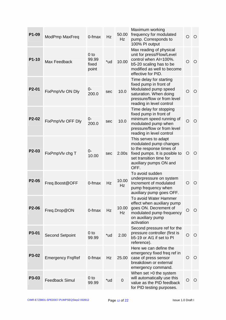
P1-09 ModPmp MaxFreq 0-fmax Hz 50.00Hz
Maximum working frequency for modulated pump. Corresponds to 100% PI output
� �
P1-10 Max Feedback
0 to 99.99 fixed point
*ud 10.00
Max reading of physical unit for press/Flow/Level control when AI=100%. b5-20 scaling has to be modified as well to become effective for PID.
� �
P2-01 FixPmpVlv ON Dly 0-200.0 sec 10.0
Time delay for starting fixed pump in front of Modulated pump speed saturation. When doing pressure/flow or from level reading in level control
� �
P2-02 FixPmpVlv OFF Dly 0-200.0 sec 10.0
Time delay for stopping fixed pump in front of minimum speed running of modulated pump when pressure/flow or from level reading in level control
� �
P2-03 FixPmpVlv chg T 0-10.00 sec 2.00s
This serves to adapt modulated pump changes to the response times of fixed pumps. It is posible to set transition time for auxiliary pumps ON and OFF.
� �
P2-05 Freq.Boost@OFF 0-fmax Hz 10.00Hz
To avoid sudden underpressure on system Increment of modulated pump frequency when auxiliary pump goes OFF.
� �
P2-06 Freq.Drop@ON 0-fmax Hz 10.00Hz
To avoid Water Hammer effect when auxiliary pump goes ON. Decrement of modulated pump frequency on auxiliary pump activation
� �
P3-01 Second Setpoint 0 to 99.99 *ud 2.00
Second pressure ref for the pressure controller (first is b5-19 or AI1 if set to PI reference).
� �
P3-02 Emergency FrqRef 0-fmax Hz 25.00
Here we can define the emergency fixed freq ref in case of press sensor breakdown or external emergency command.
� �
P3-03 Feedback Simul 0 to 99.99 *ud 0
When set >0 the system will automatically use this value as the PID feedback for PID testing purposes.
� �

CIMR-E7Z8801-SPED007-PUMPSEQStep2 050912 Page 13 of 22 Issue 1.0 Draft I
P3-05 Feedback Lo 0 to 99.99 *ud 0.50
Detection of Low feedback level and perform convenient action (depends on mode)
� �
P3-06 Feedback Hi 0 to 99.99 *ud 9.90
Detection of High feedback level alarm is set to Max pressure feedback then the alarm is deactivated
P3-07 Feedback LoLo 0 to 99.99 *ud 0.00
Detection of LowLow feedback level and perform fault after. If set to 0, the LoLo alarm is deactivated.
P3-08 Feedback HiHi 0 to 99.99 *ud 9.99
Detection of HiHi feedback level for Fault detection. If set to Max feedback level, it becomes deactivated.
� �
P3-09 Fault time 0.0-60.0 sec 5.0
Time to elapse for a pressure/level condition to become alarm/fault. 0 deactivates all fault and alarm detection...
� �
P3-10 Totalizer Reset 0-2 -- 0
Resets one of the totalizer/record monitors : 0 = No action 1 = All reset 2 = TimeTotals Once reset is done returns to zero
� �
���� = possible x = not possible *ud = unit dependant. This values will change when unit and range are changed

CIMR-E7Z8801-SPED007-PUMPSEQStep2 050912 Page 14 of 22 Issue 1.0 Draft I
4.2.3 Additional digital Input (Max 8)
Number Name (16char) Description
80h Normal/Emergency If multifunction input is closed the inverter will run in speed control with reference from emergency reference P3-02. Can be used as input for external problem indication like pressure sensor brake digital signal... For this to work correctly an additional overpressure signal is highly recommended.. When overpressure is active the inverter is stopped in any case. Using this two features, water (or any) supply can be guaranteed while inverter/motor are OK
81h Sensor LoLo Used for LoLo Level or Pressure/Flow alarm from digital input. Generates Fault after the Fault timer P3-08
82h Sensor HiHi Used for HiHi Level or Pressure/Flow alarm from digital input. Generates Fault after the Fault timer P3-08. If in Emergency Operation (broken sensor or external input) it only generates a STOP of the inverter. In this way it can be used to keep supply to the system.
83h FixPmpValv1 Over Used to override Fixed Pump or Valve 1 (ON=Override), probably coming from thermal protection of this motor or external manual override. From then it will not be included in the rotation of pumps. Its output will be kept OFF.
84h FixPmpValv2 Over Used to override Fixed Pump or Valve 2 (ON=Override), probably coming from thermal protection of this motor or external manual override. From then it will not be included in the rotation of pumps. Its output will be kept OFF.
85h FixPmpValv3 Over Used to override Fixed Pump or Valve 1 (ON=Override), probably coming from thermal protection of this motor or external manual override. From then it will not be included in the rotation of pumps. Its output will be kept OFF.
86h FixPmpValv4 Over Used to override Fixed Pump or Valve 2 (ON=Override), probably coming from thermal protection of this motor or external manual override. From then it will not be included in the rotation of pumps. Its output will be kept OFF.
87h 2nd Pmp Setpoint
This allows selection of secondary pressure/flow setpoint... Generally for Off-Peak conditions, for energy saving in the installation with lower pressure. or maintenance operation at lower pressure.

CIMR-E7Z8801-SPED007-PUMPSEQStep2 050912 Page 15 of 22 Issue 1.0 Draft I
4.2.4 Additional digital output (Max 3)
Number Name (16 char) Description
40h PumpSeq1 Out Output for the first Pump sequencer multifunction control. Action will depend on P1-04 settings
41h PumpSeq2 Out Output for the second Pump sequencer multifunction control. Action will depend on P1-05 settings
4.2.5 Additional Monitor / Analog Output (Max 10)
Access Level Param.
No.
Name (16 char)
Unit
Description V/F
U1-90 MainPmp TotalTime H Totalizer of running time for main pump. In hours up to 99999 covers more than 11 year
�
U1-91 AuxPump1 Time H Totalizer of running time for Auxiliary pump 1. This is also used for pump rotation
�
U1-92 AuxPump2 Time H Totalizer of running time for Auxiliary pump 2. This is also used for pump rotation
�
U1-93 AuxPump3 Time H Totalizer of running time for Auxiliary pump 3. This is also used for pump rotation
�
U1-94 AuxPump4 Time H Totalizer of running time for Auxiliary pump 4. This is also used for pump rotation
�

CIMR-E7Z8801-SPED007-PUMPSEQStep2 050912 Page 16 of 22 Issue 1.0 Draft I
4.2.6 Modified Analog Output settings
Access Level Param.
No.
Name (16 char)
Unit
Description V/F V/F PG
VVC FVC
H4-01 and H4-04
Analog Output terminals setting
Setting 0x31 is now “Used for PumpSeq” . With this setting, the Analog outputs are used ON-OFF from settings of P1-06 y P1-07 as additional digital outputs
� � � �
H4-02 and H4-05
Analog Output terminals gain
Defaults changed to 50%... If H4-01 and/or H4-04 is set to 0x31, then H4-02 is the voltage output level (50%=5V)
� � � �
4.2.7 Additional Fault (Max 5)
Abreviated name
Name (16 char) Description
LoLo Sensor LoLo Fault From digital input limit or internal check (P3-07 threshold level for Sensor LoLo)..
HiHi Sensor HiHi Fault From digital input limit or internal check (P3-08 threshold level for Sensor HiHi)..
In Emergency condition, this input does not generate Fault, but it gives frequency reference zero to the inverter (STOP)
DEMO DEMO Timeout In the demo version of firmware (firmware number 00xx), 1h has elapsed after inverter power on, and operation has stopped. Power cycle required for demo working again.
Abreviated name
Name (16 char) Description
DRYRN ModPump Dry RUN
When motor running with low current in motor. Prevents dry running of pump which can damage it. Adjust with parameters L6-01, L6-02, L6-03. It becomes Fault when L6-01=7 or 8. In such case inverter stops operation.
BREAK Fback sensor break Indicates broken sensor condition … The system will go to FAULT State stopping all operation if B5-12=2. For alarm behaviour and Emergency State generation B5-12=1, check next alarms listing

CIMR-E7Z8801-SPED007-PUMPSEQStep2 050912 Page 17 of 22 Issue 1.0 Draft I
4.2.8 Additional Alarm (Max 5)
Abreviated name
Name (16 char) Description
LO Lo alarm From feedback reading. (P3-05 threshold level for Sensor Lo)..
HI Hi alarm From feedback reading. (P3-06 threshold level for Sensor Hi)..
EMERG Emergency Mode Indicates work in emergency operation by digital input mode or by pressure sensor break with specific direct frequency setpoint. In this mode, the HiHi fault input is working to generate STOP in the motor.
PMPOV Pump Override Indicates some Pump is being ignored, by external input setting (set to pump override) or internal setting 4 of AuxiliaryPump Mode
MACRO LoadPumpSeqMacro Appears shortly when P1-02 is changed. Some parameters in inverter and control PID configuration have changed to adapt to the new selected working mode. For details check table of P1-02 dependent parameters.
Abreviated name
Name (16 char) Description
DRYRN ModPump Dry RUN
When motor running with low current in motor. Prevents dry running of pump which can damage it. Adjust with parameters L6-01, L6-02, L6-03. It is alarm when L6-01=5 or 6. In such case inverter continues operation with the alarm active.
BREAK Pres.sens.break Indicates broken sensor condition only with alarm (if B5-12=1)… The system will go to the emergency speed reference automatically, switching off controlled pumps.. Level and time for detect by B5-13 and B5-14. Overpressure input (highly recommended to configure) is still working protecting installation during emergency condition.

CIMR-E7Z8801-SPED007-PUMPSEQStep2 050912 Page 18 of 22 Issue 1.0 Draft I
4.2.9 Additional OPE (only 1)
Abreviated name
Name Description
OPE12 PmpSeq settings Wrong parameter settings on the system. Like : • In case of fixed duty, all auxiliary pumps have
to be set to same sequence mode (either Last ON-1st OFF or 1st ON-1st OFF).
• Emergency frequency reference is lower than minimum modulated pump frequency P1-08
4.2.10 New Defaults for standard parameters and rel evant parameter
Std pars New Name
New Deflt
New Range Hide New
Opt Standard name

CIMR-E7Z8801-SPED007-PUMPSEQStep2 050912 Page 19 of 22 Issue 1.0 Draft I
Std pars New Name
New Deflt
New Range Hide New
Opt Standard name
H3-09 -- 0xB - - - Terminal A2 sel. Default to PI Feedback
B1-08 -- 1 - - - RUN Cmd at PRG. Default to enabled
B1-04 -- 1 - hidden - Reverse Oper. Default to Reverse Disabled, hidden level
B5-01 -- 1 1-1 hidden - Only PID operation is posible
B5-17 -- 1.0 - - - Acc/Dec Time. Default to 1.0sec.
B5-11 -- - - hidden - PID Output Rev sel. Changed to hidden. In this applications, using bidirectional output is not of use.
B5-12 Fbk Sens Brk Sel 1 - - - Feedback Sensor Break Detection is activated by default as Alarm, generating emergency State.
B5-13 Fbk Sens Brk Lvl 0% - - - Feedback Sensor Break Detect level default to 0% (no signal means sensor broken)
B5-14 FbkSens Brk Time 5.0s - - - Feedback Sensor Break Det Time
B5-15 -- 21.0Hz
- - - Sleep level default to 21Hz (recommended setting is a bit higher than the minimum speed of the pump in P1-08)
B5-16 -- 5.0sec
- - - Default Sleep detection time changed to 5sec.
B5-18 -- 0 - - - By default internal setpoint B5-19 is used for PID
B5-19 -- 5.00 bar
- - - Default digital PID setpoint set to 5.00bar. This setpoint works when B5-18 is set to 1.
B5-20 PI Units Scale 21000
- - - New default Scaling for PI setpoint /feedback 00.00 to 10.00 (unit depends on P1-01 and P1-02). 10.00bar by default is standard setting
B5-03 -- 5.0 - - - PI I Time. Default increased to 5sec. It is also initialized with P1-01
C1-01 Freq ctrl Accel 5.0 - - - Accel ramp used when starting modulated pump up to the minimum frequency or when using any frequency controlled mode.
C1-02 Freq ctrl Decel 5.0 - - - Decel ramp used when stopping modulated pump or when using any frequency controlled mode.
C1-03 PIDOutput Accel 0.5 - - - Accel Time used during PID work. Applied to the final inverter frequency reference. 0.5sec for PI work
C1-04 PIDOutput Decel 0.5 - - - Decel Time used during PID work. Applied to the final

CIMR-E7Z8801-SPED007-PUMPSEQStep2 050912 Page 20 of 22 Issue 1.0 Draft I
Std pars New Name
New Deflt
New Range Hide New
Opt Standard name
inverter frequency reference. 0.5sec for PI work

CIMR-E7Z8801-SPED007-PUMPSEQStep2 050912 Page 21 of 22 Issue 1.0 Draft I
Std pars New Name
New Deflt
New Range Hide New
Opt Standard name
C1-05 AuxSwitch Accel 2.0 - - - This accel ramps will be applied to the PID output when auxiliary pumps are activated or deactivated During the switching time defined (P2-04).
C1-06 AuxSwitch Decel 2.0 - - - This decel ramps will be applied to the PID output when auxiliary pumps are activated or deactivated During the switching time defined (P2-04).
C6-01 Constant / Variable Torque 1 0–1 new - 0 = Constant Torque (compressor type).. 160% CLA level. Switching 1 = Variable Torque (Water Pump type) … 135% CLA Level up to 15KHz switching
C6-02 CarrierFreq Select KVA 0-6 (VT) 0-1 (CT)
- - Carrier frequency settings 0 to 6 (Up to 15KHz) with C6-01=1 … In Compressor mode (CT) C6-01=0 only low noise/low carrier or fixed 2.0KHz can be set
L2-05 PUV Det Level 300V - - - Undervoltage level default changed to 300Vdc (DC bus)
L5-01 -- 2 - - - Fault restart. Default to 2 restarts
L6-01 DryRUN Mode 6 5-8 - - Undertorque detection. Changed name to DryRUN 5=Dry@SpdAgre-Alm 6=Dry At RUN – Alm 7=Dry@SpdAgre-Flt 8=Dry At RUN - Flt
L6-02 DryRUN Level 15% 0-100%
DryRUN detect level. Related with inverter rated current as 100%
L6-03 DryRUN Time 10sec 0.0-60.0s
- - DryRUN detect time
H1-01 -- 87 - - - Multifunction input S3 selection changed default to 87=”2nd Pmp Setpoint”
H1-03 -- 80 - - - Multifunction input S5 selection changed default to 80=”Normal/Emergency”
H1-04 -- 83 - - - Multifunction input S6 selection changed default to 85=”FixPmpValv1 Over”
H1-05 -- 84 - - - Multifunction input S7 selection changed default to 86=”FixPmpValv2 Over”
H2-01 -- 40 - - - Multifunction Output M1-M2 selection changed default to 40=“FixPmpValv1 Out”
H2-02 -- 41 - - - Multifunction Output M3-M4 selection changed default to 41=”FixPmpValv2 Out”
H4-01 -- 31 - - - Analog Multifunction settings.

CIMR-E7Z8801-SPED007-PUMPSEQStep2 050912 Page 22 of 22 Issue 1.0 Draft I
Std pars New Name
New Deflt
New Range Hide New
Opt Standard name
31=Used by PumpSeq2 as control output 3
H4-02 -- 50% - - - New default
H4-05 -- 50% - - - New default
H4-04 -- 31 - - - Multifunction Analog Output 31=Used by PumpSeq2 as control output 4
H5-08 -- - 0-1 Not possible to use P1 FLN(Apogee) SIEMENS protocol ... Only N2 Metasys available. Under request a second version of the firmware can be created with support of P1. Both together selectable is not possible.
O1-01 User monitor sel. 24 - - - Default User monitor is PI feedback
O1-02 Power-on monitor 4 - - - Power-on monitor is User Monitor (O1-01)
O1-06 Monitor mode select 1 - - - Monitor mode is specific monitors
O1-07 2nd user monitor 20 - - - 2nd monitor is SFS frequency output
O1-08 3rd user monitor 3 - - - 3rd monitor is Output current
O2-17 Standard/IP54 Selection 0 - open - 0=Standard 1=IP54 version KVA ratings are not compatible between these two versions.
U1-24 Feedback Sensor - - - - Name changed. From PI Feedback Also special user units handling from P1-01 and P1-02 settings when B5-20>40
U1-53 Feddback Sensor2 - - - - Name changed From PI Feeedback 2