DOCUMENT N° ISSUE A Date 11/12/2003 PAGE 2 / 25
25
Transcript of DOCUMENT N° ISSUE A Date 11/12/2003 PAGE 2 / 25

DOCUMENT N° TNX 000 AR 488 E 03 ISSUE A Date 11/12/2003 PAGE 2 / 25This document is the property of EUROCOPTER, no part of it shall be reproduced or transmitted to third parties without the
express prior written authorization of EUROCOPTER nor shall its contents be disclosed. � EUROCOPTER 11/2003
MODIFICATIONS
IND. PAGE(S)MODIF.
DATE SUMMARY OF THE MODIFICATION AUTHOR VISASRESP.
SERVICE
AUTRESDIRECTIONS
MARQUEA X 11/12/2003 NEW DOCUMENT X X X

DOCUMENT N° TNX 000 AR 488 E 03 ISSUE A Date 11/12/2003 PAGE 3 / 25This document is the property of EUROCOPTER, no part of it shall be reproduced or transmitted to third parties without the
express prior written authorization of EUROCOPTER nor shall its contents be disclosed. � EUROCOPTER 11/2003
ABSTRACT
This document is a supplement to the summary report of project "Helicopter FailuresCorrection Times" phase 2, as defined in contract DGAC 99 50 075.
This document includes a theoretical study comparing the results of the Helicopter FailuresCorrection Times study, phase 2 indicated above and described in the summary reportTNX 000 AR 421 E 03 with the reactions expected by the pilots under the same failurescenarios in former generation cockpits.This additional study is a theoretical study based on Eurocopter's operational experience andon this study simulations (phase 2) dealing with the pilots' reactions in a new generationcockpit.

DOCUMENT N° TNX 000 AR 488 E 03 ISSUE A Date 11/12/2003 PAGE 4 / 25This document is the property of EUROCOPTER, no part of it shall be reproduced or transmitted to third parties without the
express prior written authorization of EUROCOPTER nor shall its contents be disclosed. � EUROCOPTER 11/2003
TABLE OF CONTENTSTABLE OF CONTENTS...................................................................................................................................... 4
LIST OF ABBREVIATIONS ............................................................................................................................... 5
1 INTRODUCTION ........................................................................................................................................ 7
2 REFERENCE DOCUMENTS..................................................................................................................... 8
3 SCOPE OF THE SURVEY.......................................................................................................................... 8
3.1 APPROACH............................................................................................................................ 93.2 TYPICAL CONFIGURATION OF A NEW-GENERATION HELICOPTER.............................................. 93.3 TYPICAL CONFIGURATION OF A PREVIOUS GENERATION HELICOPTER...................................... 93.4 TYPICAL CONFIGURATION OF A FORMER GENERATION HELICOPTER ...................................... 103.5 EXTENT OF THE SURVEY...................................................................................................... 10
3.5.1 Failures................................................................................................................. 103.5.2 Simulator .............................................................................................................. 103.5.3 Comparisons ........................................................................................................ 10
4 SUMMARY OF SIMULATIONS TO BE PERFORMED...................................................................... 11
4.1 SELECTED FAILURES ........................................................................................................... 114.2 FAILURE NO 1: SLOW IRS 2 DRIFT ..................................................................................... 11
4.2.1 Scenario Sequence.............................................................................................. 124.3 FAILURE NO 2: LOSS OF ENGINE NO 1 DETECTED BY THE FADEC....................................... 13
4.3.1 Scenario Sequence.............................................................................................. 134.4 FAILURE NO 3: REDUCTION OF ENGINE 1 POWER................................................................. 13
4.4.1 Scenario Sequence.............................................................................................. 144.5 FAILURE NO 4: SLOW DRIFT OF BAROMETRIC ALTIMETER NO 2............................................. 14
4.5.1 Scenario Sequence.............................................................................................. 154.6 FAILURE NO 5: HARDOVER ON AFCS ROLL AXIS.................................................................. 15
4.6.1 Scenario Sequence.............................................................................................. 15
5 SCENARIOS APPLIED TO PREVIOUS GENERATION HELICOPTERS ...................................... 17
5.1 FAILURE NO 1: SLOW IRS 2 DRIFT ..................................................................................... 175.1.1 Scenario Sequence.............................................................................................. 175.1.2 Comparison .......................................................................................................... 18
5.2 FAILURE NO 2: - LOSS OF ENGINE 1..................................................................................... 185.2.1 Scenario Sequence.............................................................................................. 195.2.2 Comparison .......................................................................................................... 19
5.3 FAILURE NO 3: REDUCTION OF ENGINE 1 POWER................................................................. 205.3.1 Scenario Sequence.............................................................................................. 215.3.2 Comparison .......................................................................................................... 21
5.4 FAILURE NO 4: SLOW DRIFT OF BAROMETRIC ALTIMETER NO 2 AFFECTING THE AP............... 225.4.1 Scenario Sequence.............................................................................................. 225.4.2 Comparison .......................................................................................................... 23
5.5 FAILURE NO 5: HARDOVER ON ROLL TRIM ACTUATOR .......................................................... 235.5.1 Scenario Sequence.............................................................................................. 235.5.2 Comparison .......................................................................................................... 24
6 CONCLUSION ........................................................................................................................................... 25
DOCUMENT N° TNX 000 AR 488 E 03 ISSUE A Date 11/12/2003 PAGE 5 / 25This document is the property of EUROCOPTER, no part of it shall be reproduced or transmitted to third parties without the
express prior written authorization of EUROCOPTER nor shall its contents be disclosed. � EUROCOPTER 11/2003
LIST OF ABBREVIATIONSAC Advisory CircularACJ Advisory Circular, JointADI Attitude IndicatorAFCS Automatic Flight Control SystemALT AltitudeAPU Auxiliary Power UnitBAT BatteryCAT CatastrophicCDS Control Display SystemCDP Critical Decision PointCWP Central Warning PanelEC EuroCopterECS Electrical Control SystemEGS Electrical Generation SystemEMS Emergency Medical ServiceENG EngineFADEC Full Authority Digital Engine ControlFAR Federal Aviation RegulationsFCS Flight Control SystemFHA Functional Hazard AssessmentFLI First Limitation InstrumentFLIR Forward Looking Infra-RedFND Flight & Navigation DisplayHAZ HazardousHMI Human Machine InterfaceH/C HelicopterIEBD Integrated Engine Backup DisplayIHM Interface Human MachineIMC Instrument Meteorological ConditionIPS Ice Protection SystemIRS Inertial Reference SystemJAR Joint Aviation RequirementsLDP Landing Decision PointL/G Landing GearLS Landing SystemMAJ MajorMIN MinorMGB Main Gear BoxMFD Multi Function DisplayNA Not ApplicableNAV NAVigation systemNR Nombre de tours du Rotor principalNVG Night Vision GoggleOEI One Engine InoperativeOHCP OverHead Control PanelPA Pilote AutomatiquePHL Preliminary Hazard ListPMS Plant Management SystemPT ProtoTypeRA Radio AltimeterRAGB Remote Access Gear Box

DOCUMENT N° TNX 000 AR 488 E 03 ISSUE A Date 11/12/2003 PAGE 6 / 25This document is the property of EUROCOPTER, no part of it shall be reproduced or transmitted to third parties without the
express prior written authorization of EUROCOPTER nor shall its contents be disclosed. � EUROCOPTER 11/2003
SAR Search And RescueSAS Stabilization Augmentation SystemSHA System Hazard AnalysisSOV Shut Off ValveTCAS Traffic Collision Avoidance SystemTGB Tail Gear BoxT2CAS Terrain and Traffic Collision Avoidance SystemVMC Visual Meteorological ConditionVMD Vehicle Management DisplayVNE Velocity Never to ExceedWAT Weight, Altitude, TemperatureWWWS Windshield Washer Wiper

DOCUMENT N° TNX 000 AR 488 E 03 ISSUE A Date 11/12/2003 PAGE 7 / 25This document is the property of EUROCOPTER, no part of it shall be reproduced or transmitted to third parties without the
express prior written authorization of EUROCOPTER nor shall its contents be disclosed. � EUROCOPTER 11/2003
1 IntroductionThe increasing automation of systems and the progress in helicopter technologies havemodified pilot's work. The pilot has become both a supervisor and decision-maker, the basictasks being handled by the systems.This new role and the new interfacing capabilities have made it possible to redesign theman/machine interfaces for better summary of the helicopter condition, thus enabling thepilot to ensure this new role of supervisor and decision maker.However, with system automation, the pilot is no longer in direct contact with basic helicopterdata. It is therefore necessary to insure that none of the pilot's mental representations of thehelicopter are false, and that the time required to analyze and rectify a given degradedsituation is appropriate.The current regulations specify the applicable detection and recovery time requirements inthe event of a degraded situation. These regulations must allow for the new pilot's role.The purpose of this survey was to define the technical basis necessary to amend theregulations with respect to correction times for (major or hazardous) failures that would havecatastrophic effects if the pilot fails to react quickly.During phase 1 of this survey, the following steps were performed to establish a basicreference:
� 1: Analysis of FAR/JAR 29 regulations.
� 2: Definition of failures that need to be studied.
� 3: Scope of failures to be selected.
� 4: Experiments with a reference pilot.
In the second phase of the survey, tests were conducted with a panel of 7 pilots. Theanalysis of these results demonstrated that the introduction of new cockpit technologies doesnot imply modification of the current regulations.However, during the presentation of the results from the second phase analysis, it seemedworthwhile to compare the reactions recorded during these simulation sequences and thoseexpected in former generation cockpits. This comparison forms the subject of thissupplemental document.

DOCUMENT N° TNX 000 AR 488 E 03 ISSUE A Date 11/12/2003 PAGE 8 / 25This document is the property of EUROCOPTER, no part of it shall be reproduced or transmitted to third parties without the
express prior written authorization of EUROCOPTER nor shall its contents be disclosed. � EUROCOPTER 11/2003
2 Reference DocumentsThe reference regulatory documents are:
� JAR 29 (05/11/1993)
� FAR Part 29 (15/08/1985)
� AC29-2C (30/09/1999)
� AC29-2A (16/09/1987)
� ACJ29 - subpart of JAR 29 (05/11/1993)
The summary documents of study phase 1 are:
� “Helicopter Failure Correction Times – Summary Document”– TN X 000 AR 431 E01issue A
� “Analysis of Helicopter Failure Correction Times” – TN X 000 AR 414 E01 issue B
The reference documents that are internal to the study second phase and used asintermediate reports, are:
� "Phase 2, Quarter 1" progress report – 16/07/2002 – Ref. OTSM/1074/2002 (SH)
� "Phase 2, Quarter 2" progress report -29/10/2002 – Ref. OTSM/1097/2002 (PB)
� "Phase 2, Quarter 3" progress report -20/01/2003 – Ref. OTSM/1010/2003 (BDR)
� Minutes of the meeting held on 03/12/2002 – Ref. OTSM/1011/2003 (BDR).
� "Phase 2, Quarter 4" progress report -10/04/2003 – Ref. OTSM/1048/2003 (BDR)
� Minutes of the meeting held on 23/05/2003 – Ref. OTSM/1071/2003 (BDR).
The summary documents of the study phase 2 are:
� “Helicopter Failure Correction Times - Phase 2 – Summary Document”–TN X 000 AR 421 E03 issue A
The present document is a translation of the French language document that remains thereference issue:
� “Temps de reprise en main des pannes hélicoptère - Phase 2 – Document desynthèse”– TN X 000 AR 420 F03 indice A

DOCUMENT N° TNX 000 AR 488 E 03 ISSUE A Date 11/12/2003 PAGE 9 / 25This document is the property of EUROCOPTER, no part of it shall be reproduced or transmitted to third parties without the
express prior written authorization of EUROCOPTER nor shall its contents be disclosed. � EUROCOPTER 11/2003
3 Scope of the Survey
3.1 ApproachPhase 2 of the Helicopter Failures Correction Times survey basically consisted ofexperimentation. It included the following steps:
� Selecting a panel of pilots.
� Training the pilots of the panel.
� Simulating the failure scenarios defined on phase 1.
� Analyzing and summarizing the collected data in accordance with themethods selected on phase 1.
This description does not necessarily follow a time sequence, as certain pilots weretrained immediately before simulation.These tasks were performed by specialists in human factors and simulation, with theassistance of specialists in helicopter systems and flight tests. Safety specialistsparticipated in the collected data analysis.
3.2 Typical Configuration of a New-GenerationHelicopter
This survey considered only one non-specific aircraft, which is representative of new-generation helicopters of the medium/heavy twin-engine type – i.e. within the 6 to 10metric tons range and compatible with JAR and FAR 29 regulations. This non-specificaircraft is equipped with a full glass cockpit, which includes a basic helicoptermanagement system. It includes a digital automatic flight control system (fly-by-wirecontrols) and a full-authority digital engine control (FADEC).The survey covers one- and two-pilot operation of civil helicopters. The tests wereperformed in one-pilot configuration to obtain more relevant results.
3.3 Typical Configuration of a Previous GenerationHelicopter
This comparative study is based on a non-specific aircraft. This aircraft isrepresentative of helicopters of the medium/heavy twin-engine type (i.e. within the 6 to10 metric tons range) manufactured by Eurocopter in the early 1980's. The cockpit ofthis non-specific aircraft is equipped with analog instruments and a central warningpanel. The automatic flight control system is of the duplex analog type with possibleaddition of an optional 4-axis coupler for upper modes. The engine is controlledmechanically and/or by a duplex analog electronic device. The vehicle management isdirectly performed via engraved diagrams and indicator lights on the vehiclemanagement panels.
DOCUMENT N° TNX 000 AR 488 E 03 ISSUE A Date 11/12/2003 PAGE 10 / 25This document is the property of EUROCOPTER, no part of it shall be reproduced or transmitted to third parties without the
express prior written authorization of EUROCOPTER nor shall its contents be disclosed. � EUROCOPTER 11/2003
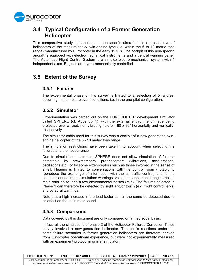
3.4 Typical Configuration of a Former GenerationHelicopter
This comparative study is based on a non-specific aircraft. It is representative ofhelicopters of the medium/heavy twin-engine type (i.e. within the 6 to 10 metric tonsrange) manufactured by Eurocopter in the early 1970's. The cockpit of this non-specificaircraft is equipped with electro-mechanical instruments and a central warning panel.The Automatic Flight Control System is a simplex electro-mechanical system with 4independent axes. Engines are hydro-mechanically controlled.
3.5 Extent of the Survey
3.5.1 FailuresThe experimental phase of this survey is limited to a selection of 5 failures,occurring in the most relevant conditions, i.e. in the one-pilot configuration.
3.5.2 SimulatorExperimentation was carried out on the EUROCOPTER development simulatorcalled SPHERE (cf. Appendix 1), with the external environment image beingprojected over a fixed, non-vibrating field of 180 x 80° horizontally and vertically,respectively.The simulator cabin used for this survey was a cockpit of a new-generation twin-engine helicopter of the 8 - 10 metric tons range.The simulation restrictions have been taken into account when selecting thefailures and their occurrence.Due to simulation constraints, SPHERE does not allow simulation of failuresdetectable by crewmembers' proprioceptors (vibrations, accelerations,oscillations,etc.) or by some exteroceptors such as those involved in the sense ofsmell. Hearing is limited to conversations with the control room (notably toreproduce the exchange of information with the air traffic control) and to thesounds planned in the simulation: warnings, voice announcements, engine noise;main rotor noise, and a few environmental noises (rain). The failures selected inPhase 1 can therefore be detected by sight and/or touch (e.g. flight control jerks)and by aural warnings.Note that a high increase in the load factor can all the same be detected due toits effect on the main rotor sound.
3.5.3 ComparisonsData covered by this document are only compared on a theoretical basis.In fact, all the simulations of phase 2 of the Helicopter Failures Correction Timessurvey involved a new-generation helicopter. The pilot's reactions under thesame failure scenarios in former generation helicopters are therefore derivedfrom Eurocopter operational experience, but were not experimentally measuredwith an experiment protocol in similar simulator.

DOCUMENT N° TNX 000 AR 488 E 03 ISSUE A Date 11/12/2003 PAGE 11 / 25This document is the property of EUROCOPTER, no part of it shall be reproduced or transmitted to third parties without the
express prior written authorization of EUROCOPTER nor shall its contents be disclosed. � EUROCOPTER 11/2003
4 Summary of Simulations To Be PerformedA more detailed description of the simulations performed during Phase 2 of the HelicopterFailures Correction Times survey are given in the summary report TN X 000 AR 421 E03.
4.1 Selected FailuresThe 5 failures selected during phase 1 and their associated occurrence are as follows:
Failure Occurrence
1 Slow IRS2 drift at 2.4°/s Cruise in IMC conditions
2 Loss of one engine detected by FADEC HOVER while sling loading operation is inprogress
3 Partial loss of engine power VMC approach during night landing
4 Slow drift of the AP altitude hold upon abarometric altimeter failure
Cruise in IMC conditions
5 Hardover on AFCS roll axis Cruise in VMC conditions at low altitude
4.2 Failure No 1: Slow IRS 2 DriftThe slow IRS2 drift failure was selected for its « slowover » aspect detectable by thepilot. It is an illustration of the potential temporal drift of a failure, after detection of adeviation between the 2 IRS's, if the pilot does not execute positive cross-checks of thedata from the various equipment.
FAILURE DETECTION ELEMENTS FAILURE CORRECTION
- Nose-down movement and RH roll attitudedisplayed on pilot FND
- Loss of upper modes (ALT, speed, attitudehold)
- Deviation between the 2 FND symbologies
- “HANDS ON” audio warning
- Temporary illumination of “FCS” red warninglight (meaning « hands on »)+ “FCS” and“AVICS” (amber) on CWP
- Cross check between both displays/stand-by instrument
- Warning acknowledgement
- Identification of display providing falseinformation
- MFD2 reconfiguration on IRS1
* Automatic AFCS switch off

DOCUMENT N° TNX 000 AR 488 E 03 ISSUE A Date 11/12/2003 PAGE 12 / 25This document is the property of EUROCOPTER, no part of it shall be reproduced or transmitted to third parties without the
express prior written authorization of EUROCOPTER nor shall its contents be disclosed. � EUROCOPTER 11/2003
4.2.1 Scenario SequenceThe failure is initiated in a steady cruise flight in IMC conditions. The first sign ofthe failure, which was only detected by one pilot, is an attitude indicator thatstarts to deflect as if for the beginning of a turn.When the attitude difference between the two IRS units reaches 3°, the systemdetects the anomaly after 1.25 s and initiates the following actions:
� hands-on warning including:� disconnection of the AFCS upper modes;� the AFCS zone indicators on the MFD flash red;� temporary red FCS on the CWP;� hands-on audio warning;
� warning indicating the avionics/AFCS problem (AFCS detectsdiscrepancy) and including:� amber FCS on the CWP;� amber AVICS on the CWP;
The pilot can consult the FCS or avionic pages on the VMD and see that the IRSare indicated as being unreliable (amber). However, this check can only be madesubsequently as the recovery action must be fast.As the pilots have been told during training, when an AVICS failure is indicated,the attitude indicators and the standby indicator must be read before attemptingto use the indicator in front of the pilot for flying. The failure may then be analyzedin more detail via the VMD pages.In the simulations, the pilots behaved as follows:
� Pilot 2 detected an abnormal deflection on the attitude indicator before thewarning, which confirmed his analysis of a problem with this indicator
� Pilots 3, 6 and 7 carried out the check as soon as the warning occurred.Pilot 3 reconfigured before re-engaging the AFCS. Pilot 7 decided to flyusing the standby indicators. Pilot 6 knew he was above the Etang deBerre and simply decreased the collective pitch to initiate a descent underthe cloud layer to regain some visual cues.
� Pilots 1, 4 and 5 started to follow the failed IRS. Pilot 1 quickly analyzedthe problem by detecting the discrepancies between his apparent attitudeand the heading variations. Pilot 4 and 5 took longer to complete thisanalysis and were alerted by the effect of the load factor (not detecteddirectly on the simulator) on the main rotor noise or because they haddescended below the cloud layer.

DOCUMENT N° TNX 000 AR 488 E 03 ISSUE A Date 11/12/2003 PAGE 13 / 25This document is the property of EUROCOPTER, no part of it shall be reproduced or transmitted to third parties without the
express prior written authorization of EUROCOPTER nor shall its contents be disclosed. � EUROCOPTER 11/2003
4.3 Failure No 2: Loss of Engine No 1 Detected By TheFADEC
The engine 1 loss failure was selected as an obvious failure detectable by the system.This illustrates a failure degrading helicopter controllability (loss of power margin) andoccurring simultaneously in a flight phase requiring high piloting skill.
FAILURE DETECTION ELEMENTS FAILURE CORRECTION- Engine No 2 switched to OEI mode- Engine parameters modification displayed withred warnings on IEBD- OEI mode reported on the FND's
- “ENG DF” red warnings on CWP and audiowarning
- release of the sling load- Lower collective pitch to retain rotor NR
- Accelerate (push cyclic stick forward) andcontrol path (obstacle avoidance)- Warning acknowledged
- Switch engine No 1 off to prevent fuelsupply
4.3.1 Scenario SequenceThe engine failure is initiated in the very short final approach to an offshore rig.The helicopter is virtually in hovering flight, almost over the platform, or evenalready over the platform for those pilots who opted for a very low approachspeed.The engine failure triggers a red ENG DF warning on the CWP, and displays theFLI scale on the FND in OEI mode.Notwithstanding the reminder in the briefing of the necessity to immediatelyrelease the load in case of a problem, the first reaction of all the pilots was tocontrol the helicopter. Whereas some pilots released the load in the ensuingseconds, others concentrated on managing the flight path and power, onlyperforming release afterwards.Only one pilot (pilot 1) decided to pursue his landing. He nevertheless took thetime to steady the helicopter in IGE hover in order to check over the radiowhether the released load had caused excessive damage to the platform. All theother pilots elected to take advantage of the platform's height above the sea topick up speed again.
4.4 Failure No 3: Reduction of Engine 1 PowerThe partial reduction of engine 1 was selected for its « slowover » aspect that is notquickly detectable by the pilot. This illustrates the potential temporal drift of a failureand the pilotability degradation it induces.This failure also illustrates a loss of helicopter performance in a high workload phase,requiring the pilot to make a priority selection.
DOCUMENT N° TNX 000 AR 488 E 03 ISSUE A Date 11/12/2003 PAGE 14 / 25This document is the property of EUROCOPTER, no part of it shall be reproduced or transmitted to third parties without the
express prior written authorization of EUROCOPTER nor shall its contents be disclosed. � EUROCOPTER 11/2003
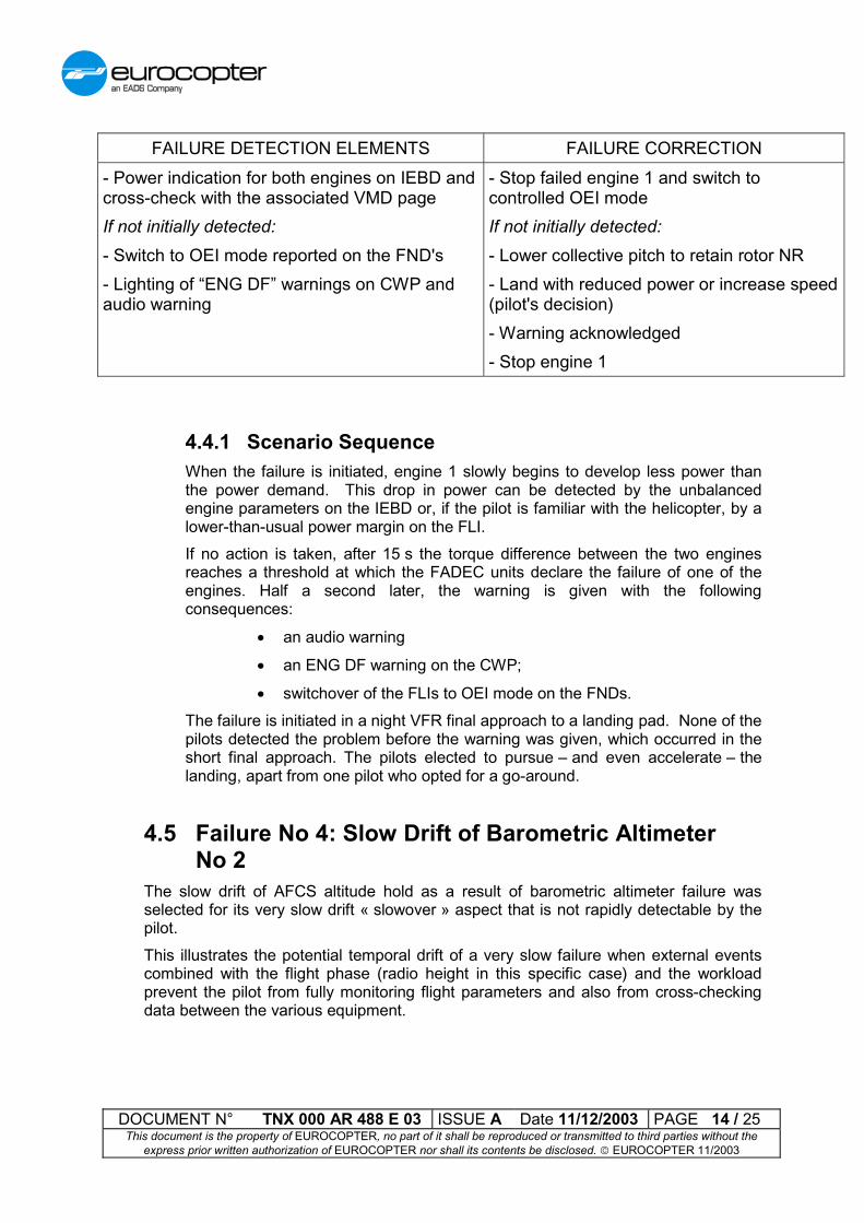
FAILURE DETECTION ELEMENTS FAILURE CORRECTION- Power indication for both engines on IEBD andcross-check with the associated VMD pageIf not initially detected:- Switch to OEI mode reported on the FND's- Lighting of “ENG DF” warnings on CWP andaudio warning
- Stop failed engine 1 and switch tocontrolled OEI modeIf not initially detected:- Lower collective pitch to retain rotor NR- Land with reduced power or increase speed(pilot's decision)- Warning acknowledged- Stop engine 1
4.4.1 Scenario SequenceWhen the failure is initiated, engine 1 slowly begins to develop less power thanthe power demand. This drop in power can be detected by the unbalancedengine parameters on the IEBD or, if the pilot is familiar with the helicopter, by alower-than-usual power margin on the FLI.If no action is taken, after 15 s the torque difference between the two enginesreaches a threshold at which the FADEC units declare the failure of one of theengines. Half a second later, the warning is given with the followingconsequences:
� an audio warning
� an ENG DF warning on the CWP;
� switchover of the FLIs to OEI mode on the FNDs.The failure is initiated in a night VFR final approach to a landing pad. None of thepilots detected the problem before the warning was given, which occurred in theshort final approach. The pilots elected to pursue – and even accelerate – thelanding, apart from one pilot who opted for a go-around.
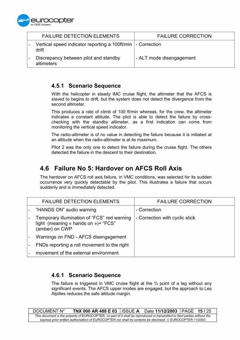
4.5 Failure No 4: Slow Drift of Barometric AltimeterNo 2
The slow drift of AFCS altitude hold as a result of barometric altimeter failure wasselected for its very slow drift « slowover » aspect that is not rapidly detectable by thepilot.This illustrates the potential temporal drift of a very slow failure when external eventscombined with the flight phase (radio height in this specific case) and the workloadprevent the pilot from fully monitoring flight parameters and also from cross-checkingdata between the various equipment.
DOCUMENT N° TNX 000 AR 488 E 03 ISSUE A Date 11/12/2003 PAGE 15 / 25This document is the property of EUROCOPTER, no part of it shall be reproduced or transmitted to third parties without the
express prior written authorization of EUROCOPTER nor shall its contents be disclosed. � EUROCOPTER 11/2003
FAILURE DETECTION ELEMENTS FAILURE CORRECTION- Vertical speed indicator reporting a 100ft/min
drift- Discrepancy between pilot and standby
altimeters
- Correction
- ALT mode disengagement
4.5.1 Scenario SequenceWith the helicopter in steady IMC cruise flight, the altimeter that the AFCS isslaved to begins to drift, but the system does not detect the divergence from thesecond altimeter.This produces a rate of climb of 100 ft/min whereas, for the crew, the altimeterindicates a constant altitude. The pilot is able to detect the failure by cross-checking with the standby altimeter, as a first indication can come frommonitoring the vertical speed indicator.The radio-altimeter is of no value in detecting the failure because it is initiated atan altitude when the radio-altimeter is at its maximum.Pilot 2 was the only one to detect the failure during the cruise flight. The othersdetected the failure in the descent to their destination.
4.6 Failure No 5: Hardover on AFCS Roll AxisThe hardover on AFCS roll axis failure, in VMC conditions, was selected for its suddenoccurrence very quickly detectable by the pilot. This illustrates a failure that occurssuddenly and is immediately detected.
FAILURE DETECTION ELEMENTS FAILURE CORRECTION- “HANDS ON” audio warning- Temporary illumination of “FCS” red warning
light (meaning « hands on »)+ “FCS”(amber) on CWP
- Warnings on FND - AFCS disengagement- FNDs reporting a roll movement to the right- movement of the external environment
- Correction- Correction with cyclic stick
4.6.1 Scenario SequenceThe failure is triggered in VMC cruise flight at the ¾ point of a leg without anysignificant events. The AFCS upper modes are engaged, but the approach to LesAlpilles reduces the safe altitude margin.

DOCUMENT N° TNX 000 AR 488 E 03 ISSUE A Date 11/12/2003 PAGE 16 / 25This document is the property of EUROCOPTER, no part of it shall be reproduced or transmitted to third parties without the
express prior written authorization of EUROCOPTER nor shall its contents be disclosed. � EUROCOPTER 11/2003
When the failure is triggered, the following events occur immediately:
� the roll trim actuator goes hardover, causing roll to the right:� movement of the external environment;� the attitude indicators indicate rolling to the right;
� hands-on warning including:� disconnection of the AFCS upper modes;� the AFCS zone indicators on the MFD flash red;� temporary red FCS on the CWP;� hands-on audio warning;
� warning indicating the AFCS problem
� amber FCS on the CWP.By checking the FCS pages on the VMD, the pilot observes the failuredeclaration for the roll trim actuator (amber). However, this check can only bemade subsequently as the recovery action must be fast.All the pilots reacted by immediately implementing manual recovery andstabilizing the helicopter. They then used the VMD to analyze the failure.It is pointed out that pilot 6, who had maintained a cruise altitude of 1,200 ft, wasin the process of switching to manual mode for climbing over Les Alpilles whenthe failure occurred

DOCUMENT N° TNX 000 AR 488 E 03 ISSUE A Date 11/12/2003 PAGE 17 / 25This document is the property of EUROCOPTER, no part of it shall be reproduced or transmitted to third parties without the
express prior written authorization of EUROCOPTER nor shall its contents be disclosed. � EUROCOPTER 11/2003
5 Scenarios Applied to Previous GenerationHelicopters
5.1 Failure No 1: Slow IRS 2 DriftThis failure is not to be considered on former generation helicopters since their artificialhorizons are generally independent of the AFCS vertical indicator. In the case wherethe artificial horizons use the vertical information from the AFCS IRS's, this would beequivalent to the scenario occurring on new-generation aircraft.Therefore, two cases will be considered: a pilot's artificial horizon drift or an AFCSvertical indicator drift resulting in a roll movement. In the latter case, the aircraft has tobe provided with a simplex AFCS (or initiating a flight on a duplex AFCS with a failedchannel).
FAILURE DETECTION ELEMENTS FAILURE CORRECTION- Nose-down and roll movements displayed on
the pilot artificial horizon- If the failure is an AFCS failure and if it is not
detected by the pilot, the AFCS switches off(with alert signal) when it can no longerfollow its vertical indicator as the helicopterattitude becomes excessive.
- Correction- AFCS switch off- cross check of both 2 ADI / standby
horizon- identification of the failed system;
� depending on the diagnosis, in case of apilot's horizon problem:- AFCS reengagement- Monitoring of AFCS behaviour using
standby horizon
� or (if AFCS problem):- manual piloting on roll and pitch axes
5.1.1 Scenario SequenceThe failure is initiated in a steady cruise flight in IMC conditions. The first sign ofthe failure is an artificial horizon that starts to deflect as if for the beginning of aturn.Then the pilot has to recover manual control and observe his standby horizon soas not to blindly follow the indications of his main horizon.If the pilot's horizon is defective, the AFCS can be reengaged, observing theattitude of the helicopter on the standby horizon. Otherwise, the pilot will have topursue his flight by manual piloting on the roll and pitch axes using the cyclicstick.

DOCUMENT N° TNX 000 AR 488 E 03 ISSUE A Date 11/12/2003 PAGE 18 / 25This document is the property of EUROCOPTER, no part of it shall be reproduced or transmitted to third parties without the
express prior written authorization of EUROCOPTER nor shall its contents be disclosed. � EUROCOPTER 11/2003
5.1.2 ComparisonIn contrast to the new generation helicopters, this failure poses two problems: thedetection and the resolution of the failure.In the former generation aircraft, the failure is not detected by the system but bythe pilot. This is of no importance in the case of an horizon failure since the APstill maintains the aircraft horizontal. However, if the pilot is not attentive, thismay lead to a hazardous situation in case of an AP malfunctioning. However, itcan be pointed out that a former generation simplex AP is rather a stabilizationaid (the pilot keeping full control of the helicopter) than an AP in its modernmeaning. . It is therefore unlikely that the aircraft starts turning without beingdetected in this configuration.In the event of an AP failure, correction is rather easy: the pilot can follow hisinstinctive reflex consisting in recovering manual control and stabilizing thehelicopter using the indications of his artificial horizon. However, any pilot'shorizon failure requires the pilot to check the standby horizon before attemptingto recover from a situation perceived as an accidental turning. Nothing indicatesthat the 3 pilots who started to follow the failed horizon in the new generationaircraft would not have react in the same manner in this specific case.To summarize, if the failure appears more complex in new generation aircraftsince a same sensor can deliver information to several equipment items, thisadvanced system also helps the pilots in detecting the failure. Moreover, thissystem allows the aircraft to be reconfigured for piloting with the correct inertialreference source, thus reducing the workload compared with that required forstandby horizon piloting in the former cockpits.
5.2 Failure No 2: - Loss of Engine 1The engine 1 loss failure was selected as an obvious failure detectable by the system.This illustrates a failure degrading helicopter controllability (loss of power margin) andoccurring simultaneously in a flight phase requiring high piloting skill
The failure is different depending on whether it occurs on a helicopter of the previousgeneration or an older helicopter. With the helicopters of the previous generation:
FAILURE DETECTION ELEMENTS FAILURE CORRECTION- Drop of Ng, T4, torque and NTL of engine 1- NG.DIFF. and PRESS.1 warnings (central
panel), + ALARM warning light- then, depending on the load release rapidity
and on the collective pitch decrease rate:- PWR.1 warning (dedicated light)- NR.MIN warning (dedicated light + audio
warning)
- release of the sling load- Lower collective pitch to retain rotor NR, if
needed- Accelerate (push cyclic stick forward) and
control path (obstacle avoidance)- Switch engine No 1 off to prevent fuel
supply
DOCUMENT N° TNX 000 AR 488 E 03 ISSUE A Date 11/12/2003 PAGE 19 / 25This document is the property of EUROCOPTER, no part of it shall be reproduced or transmitted to third parties without the
express prior written authorization of EUROCOPTER nor shall its contents be disclosed. � EUROCOPTER 11/2003
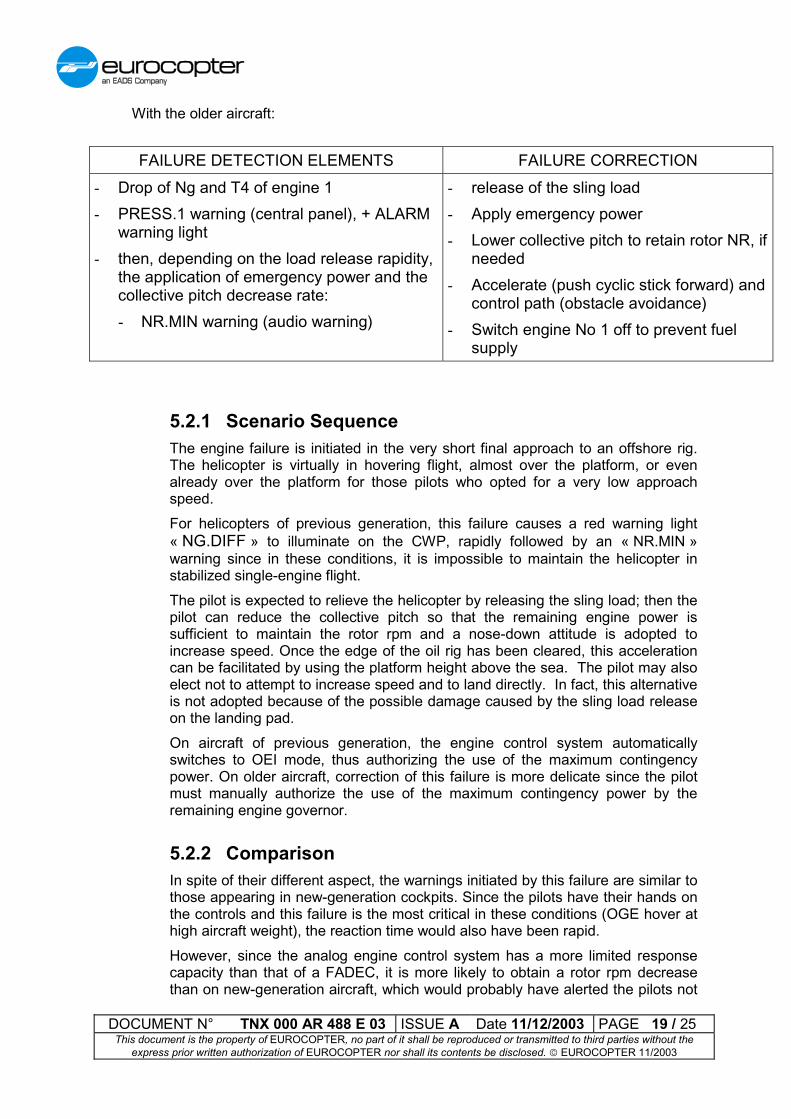
With the older aircraft:
FAILURE DETECTION ELEMENTS FAILURE CORRECTION- Drop of Ng and T4 of engine 1- PRESS.1 warning (central panel), + ALARM
warning light- then, depending on the load release rapidity,
the application of emergency power and thecollective pitch decrease rate:- NR.MIN warning (audio warning)
- release of the sling load- Apply emergency power- Lower collective pitch to retain rotor NR, if
needed- Accelerate (push cyclic stick forward) and
control path (obstacle avoidance)- Switch engine No 1 off to prevent fuel
supply
5.2.1 Scenario SequenceThe engine failure is initiated in the very short final approach to an offshore rig.The helicopter is virtually in hovering flight, almost over the platform, or evenalready over the platform for those pilots who opted for a very low approachspeed.For helicopters of previous generation, this failure causes a red warning light« NG.DIFF » to illuminate on the CWP, rapidly followed by an « NR.MIN »warning since in these conditions, it is impossible to maintain the helicopter instabilized single-engine flight.The pilot is expected to relieve the helicopter by releasing the sling load; then thepilot can reduce the collective pitch so that the remaining engine power issufficient to maintain the rotor rpm and a nose-down attitude is adopted toincrease speed. Once the edge of the oil rig has been cleared, this accelerationcan be facilitated by using the platform height above the sea. The pilot may alsoelect not to attempt to increase speed and to land directly. In fact, this alternativeis not adopted because of the possible damage caused by the sling load releaseon the landing pad.On aircraft of previous generation, the engine control system automaticallyswitches to OEI mode, thus authorizing the use of the maximum contingencypower. On older aircraft, correction of this failure is more delicate since the pilotmust manually authorize the use of the maximum contingency power by theremaining engine governor.
5.2.2 ComparisonIn spite of their different aspect, the warnings initiated by this failure are similar tothose appearing in new-generation cockpits. Since the pilots have their hands onthe controls and this failure is the most critical in these conditions (OGE hover athigh aircraft weight), the reaction time would also have been rapid.However, since the analog engine control system has a more limited responsecapacity than that of a FADEC, it is more likely to obtain a rotor rpm decreasethan on new-generation aircraft, which would probably have alerted the pilots not
DOCUMENT N° TNX 000 AR 488 E 03 ISSUE A Date 11/12/2003 PAGE 20 / 25This document is the property of EUROCOPTER, no part of it shall be reproduced or transmitted to third parties without the
express prior written authorization of EUROCOPTER nor shall its contents be disclosed. � EUROCOPTER 11/2003
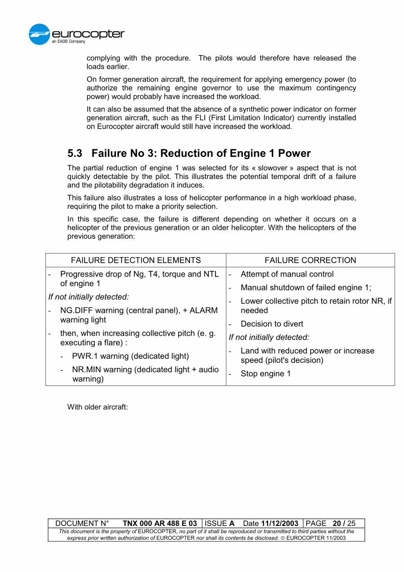
complying with the procedure. The pilots would therefore have released theloads earlier.On former generation aircraft, the requirement for applying emergency power (toauthorize the remaining engine governor to use the maximum contingencypower) would probably have increased the workload.It can also be assumed that the absence of a synthetic power indicator on formergeneration aircraft, such as the FLI (First Limitation Indicator) currently installedon Eurocopter aircraft would still have increased the workload.
5.3 Failure No 3: Reduction of Engine 1 PowerThe partial reduction of engine 1 was selected for its « slowover » aspect that is notquickly detectable by the pilot. This illustrates the potential temporal drift of a failureand the pilotability degradation it induces.This failure also illustrates a loss of helicopter performance in a high workload phase,requiring the pilot to make a priority selection.In this specific case, the failure is different depending on whether it occurs on ahelicopter of the previous generation or an older helicopter. With the helicopters of theprevious generation:
FAILURE DETECTION ELEMENTS FAILURE CORRECTION- Progressive drop of Ng, T4, torque and NTL
of engine 1If not initially detected:- NG.DIFF warning (central panel), + ALARM
warning light- then, when increasing collective pitch (e. g.
executing a flare) :- PWR.1 warning (dedicated light)- NR.MIN warning (dedicated light + audio
warning)
- Attempt of manual control- Manual shutdown of failed engine 1;- Lower collective pitch to retain rotor NR, if
needed- Decision to divertIf not initially detected:- Land with reduced power or increase
speed (pilot's decision)- Stop engine 1
With older aircraft:

DOCUMENT N° TNX 000 AR 488 E 03 ISSUE A Date 11/12/2003 PAGE 21 / 25This document is the property of EUROCOPTER, no part of it shall be reproduced or transmitted to third parties without the
express prior written authorization of EUROCOPTER nor shall its contents be disclosed. � EUROCOPTER 11/2003
FAILURE DETECTION ELEMENTS FAILURE CORRECTION- Progressive drop of Ng, T4, torque and NTL
of engine 1if not initially detected, when increasingcollective pitch (e. g. executing a flare) :- NR.MIN warning (audio warning)
- Attempt of manual control- Apply emergency power- Manual shutdown of failed engine 1;- Lower collective pitch to retain rotor NR, if
needed- Decision to divertIf not initially detected:- Apply emergency power- Land with reduced power or increase
speed (pilot's decision)- Stop engine 1
5.3.1 Scenario SequenceWhen the failure is initiated, engine 1 slowly begins to develop less power thanthe power demand. This drop can be detected by a mismatch of the displayedengines parameters.If no action is taken, the torque difference between the two engines reaches athreshold at which the NG difference warning is triggered by the monitoring logic.The failure is initiated so that this threshold is reached at the decision point.Then, if the power demand becomes sufficiently high to decrease rotor RPM, thelow NR and engine 1 power loss warnings are triggered In fact, in an analogcontrol system of this generation, as long as the rotor RPM remains nominal, it isimpossible for the monitoring system to know whether engine 1 loses powerbecause of a failure or in response to an overspeed condition of engine 2.In the case when the initial degradation has not been detected, the scenario ismore hazardous on older aircraft since the control system is not able to output anengine failure signal. Therefore, when the NR warning is triggered during a flareexecution, the pilot must analyze the reason of the lack of engine power, switchto emergency power mode and complete landing (or elect to perform a go-around) with a single engine. In practice, the priority in short final approach is tolook outside the cockpit (controlling the flight path and the touchdown area), withadditional workload due to night flight. It is therefore probable that the pilot willdecide to complete the landing before analyzing the failure. This will result in"hard" landing.
5.3.2 ComparisonIn this case, the pilot does not receive any warning before the decision point isreached. In former helicopters, the pilot does not even receive a warning beforethe rotor speed is decreased by a manoeuver.It is therefore logic for the pilot to proceed with the landing. The only significantdifference between new-generation helicopters and helicopters of the previous

DOCUMENT N° TNX 000 AR 488 E 03 ISSUE A Date 11/12/2003 PAGE 22 / 25This document is the property of EUROCOPTER, no part of it shall be reproduced or transmitted to third parties without the
express prior written authorization of EUROCOPTER nor shall its contents be disclosed. � EUROCOPTER 11/2003
generation would lie in the better reactivity of the digital control system, slightlyreducing the risk for hard landing. However, former helicopters are significantlymore exposed to this risk since a pilot that would not have detected the engineprior degradation, would not be alerted before engine power becomes insufficientwhen executing the flare.Should the pilot hear the warning before the decision point is reached or detectan initial drift of the engine parameters, the approach procedure would logicallybe interrupted although several options are proposed by the procedure. Butduring the simulations, it was seen that during night flights with a single pilot,searching for appropriate touchdown point increased the pilot's workload, thusmaking correct monitoring of engine instruments rather improbable.Moreover, night landing with former aircraft on unprepared terrain requires thepresence of a second crewmember for monitoring the vehicle and moreparticularly the engines.
5.4 Failure No 4: Slow Drift of Barometric AltimeterNo 2 affecting the AP
The slow drift of AFCS altitude hold as a result of barometric altimeter failure wasselected for its very slow drift « slowover » aspect that is not rapidly detectable by thepilot.This illustrates the potential temporal drift of a very slow failure when external eventscombined with the flight phase (radio height in this specific case) and the workloadprevent the pilot from fully monitoring flight parameters and also from cross-checkingdata between the various equipment.This failure is not to be considered on former generation helicopters. In fact, the AP isequipped with its own altimeter (whose indication is not visible by the crew), and thistype of drift is generally due to an internal failure of the measuring instrument (e. g. leakin the barometric cell). However, in this study, priority will be given to a failure categoryrather than to a specific scenario. Even if this is not realistic, we will therefore considerthat the concerned non-specific helicopter presents a failure mode inducing a commondrift of both pilot's and AP altimeters, for example via static ports.
FAILURE DETECTION ELEMENTS FAILURE CORRECTION- Vertical speed indicator reporting a 100ft/min
drift- Discrepancy between pilot and standby
altimeters
- Correction- Altitude hold disengagement- transition to « standby static pressure »
5.4.1 Scenario SequenceWith the helicopter in steady IMC cruise flight, the altimeter that the AFCS isslaved to begins to drift, and an hypothetical common mode induces the samedrift on the pilot's altimeter.This produces a rate of climb of 100 ft/min whereas, for the crew, the altimeterindicates a constant altitude. The pilot is able to detect the failure by cross-

DOCUMENT N° TNX 000 AR 488 E 03 ISSUE A Date 11/12/2003 PAGE 23 / 25This document is the property of EUROCOPTER, no part of it shall be reproduced or transmitted to third parties without the
express prior written authorization of EUROCOPTER nor shall its contents be disclosed. � EUROCOPTER 11/2003
checking with the standby altimeter, as a first indication can come frommonitoring the vertical speed indicator.The radio-altimeter is of no value in detecting the failure because it is initiated atan altitude when the radio-altimeter is at its maximum.
5.4.2 ComparisonIn this case of failure, there would be no reason for the pilots to react in adifferent manner than in new-generation cockpit.In fact, the pilots always have to regularly check that their «Basic T» indicationsare consistent with those displayed on the standby instruments. However, it shallbe noted that, to extend the scope of the survey to lighter aircraft or dual controls,a cross-checking function for pitot-static indications had been disabled on new-generation aircraft. Therefore, the latter is capable of informing the pilots of thepresence of an altimeter problem. This function was not provided on formeraircraft.
5.5 Failure No 5: Hardover On Roll Trim ActuatorThe hardover on AFCS roll axis failure, in VMC conditions, was selected for its suddenoccurrence very quickly detectable by the pilot. This illustrates a failure that occurssuddenly and is immediately detected.
FAILURE DETECTION ELEMENTS FAILURE CORRECTION- Artificial horizons reporting a roll movement
to the right- movement of the external environment;- if required (depending on aircraft
generation):
� Indication of AFCS failure (amber light)
� AFCS disengagement warning
- Correction- Correction with cyclic stick- AFCS disconnection
5.5.1 Scenario SequenceThe failure is triggered in VMC cruise flight at the ¾ point of a leg without anysignificant events. The AFCS upper modes are engaged, but the approach to LesAlpilles reduces the safe altitude margin.When the failure is triggered, the following events occur immediately:
� movement of the external environment;
� the attitude indicators indicate rolling to the right;Depending on the aircraft design, the AFCS can detect the failure, causingillumination of an AFCS failure amber warning light and disconnection of theAFCS (or at least of the roll channel) along with the corresponding alert signal.
DOCUMENT N° TNX 000 AR 488 E 03 ISSUE A Date 11/12/2003 PAGE 24 / 25This document is the property of EUROCOPTER, no part of it shall be reproduced or transmitted to third parties without the
express prior written authorization of EUROCOPTER nor shall its contents be disclosed. � EUROCOPTER 11/2003
The pilot is expected to immediately proceed to manual recovery and stabilizationof the aircraft (if needed overriding the AFCS). After analysis of the failure, thepilot will switch off the AFCS and release the trim feel loads on roll axis, even cutoff AFCS hydraulic pressure. Then, depending on the systems, the pilot can re-engage the other channels.
5.5.2 ComparisonIn this case of failure, there are few reasons for the pilots to react in a differentmanner than in new-generation cockpits.In fact, the failure results in a sudden movement of the external environment, feltas a very strong indication by all the pilots. The major difference lies in theexistence, on new-generation helicopters, of a « hands-on » alert signalling thenecessity for immediate manual recovery of the aircraft. This alert signalcombined with the temporary illumination of a red light, increases the criticality ofthe situation. But in the scenario under study, in good weather conditions, it isprobable that these indications are not needed by the pilots.

DOCUMENT N° TNX 000 AR 488 E 03 ISSUE A Date 11/12/2003 PAGE 25 / 25This document is the property of EUROCOPTER, no part of it shall be reproduced or transmitted to third parties without the
express prior written authorization of EUROCOPTER nor shall its contents be disclosed. � EUROCOPTER 11/2003
6 ConclusionThe results of this complementary study are consistent with the assumption that hadoriginated the Helicopter Failures Correction Times survey, i.e.: on any advanced technologyaircraft, the pilot spends less time flying the helicopter than managing the systems.In fact, it can be pointed out that, for the scenarios retained in this survey, the failuresobtained for new-generation aircraft are:
� a little more complex to analyze, due to the interconnection between the varioussystems, which can lead to several effects for a same failure depending on theexact configuration of the aircraft at the time of the failure occurrence;
� but more easy to detect thanks to the various monitoring functions achievable bythis system interconnection, which allows the pilot to be informed directly by thesystem;
Moreover, the pilot can use the system as an aid for the failure diagnosis. He can oftenreconfigure the system so that the system operates in a virtually nominal mode. Forexample, upon an IRS failure, the pilot can display on his screeen the data of the valid IRSor the standby instrument instead of piloting the aircraft using this standby instrument whichis not directly in the pilot's field of view.Therefore, the pilot's role is changing. His tasks include less "conventional" vehicle controland monitoring actions and more system and configuration management operations.However, as previously demonstrated by the simulations performed for this survey, thewarning and aid provisions in a modern system ensure pilot's failure correction timescomplying with the regulations established for former systems and even allow the risksrelated to the failure consequences to be reduced.