Document: BL R0 PRESSURE CONTROL VALVE · PDF fileEach Pressure Control Valve™ is...
16
NOTICE This bulletin contains important safety information and should be read and understood by all installation and operation personnel. PRESSURE CONTROL VALVE ™ INSTALLATION & OPERATION MANUAL A TMOSPHERE E NGINEERING C OMPANY Phone: 414-331-2457; Fax: 414-332-2457 Email: [email protected] Web: www.atmoseng.com Document: BL-3389-R0 PCV Operation Manual
Transcript of Document: BL R0 PRESSURE CONTROL VALVE · PDF fileEach Pressure Control Valve™ is...
Page 1
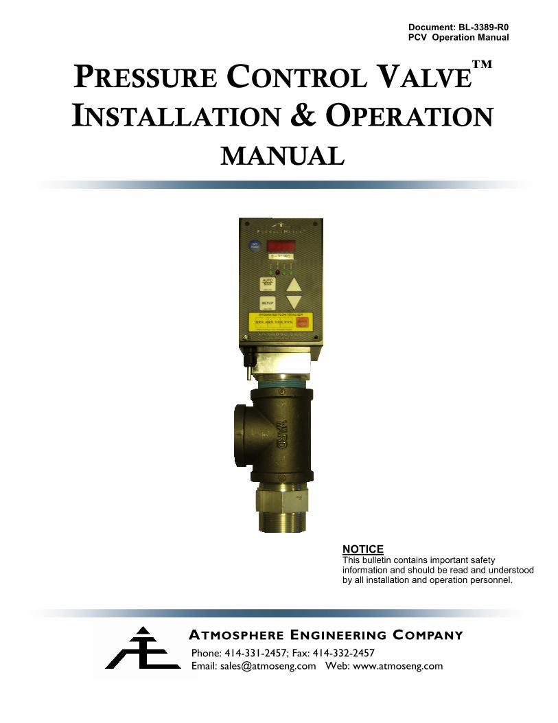
NOTICE This bulletin contains important safety information and should be read and understood by all installation and operation personnel.
PRESSURE CONTROL VALVE™
INSTALLATION & OPERATION
MANUAL
ATMOSPHERE ENGINEERING COMPANY
Phone: 414-331-2457; Fax: 414-332-2457
Email: [email protected] Web: www.atmoseng.com
Document: BL-3389-R0 PCV Operation Manual
Page 2
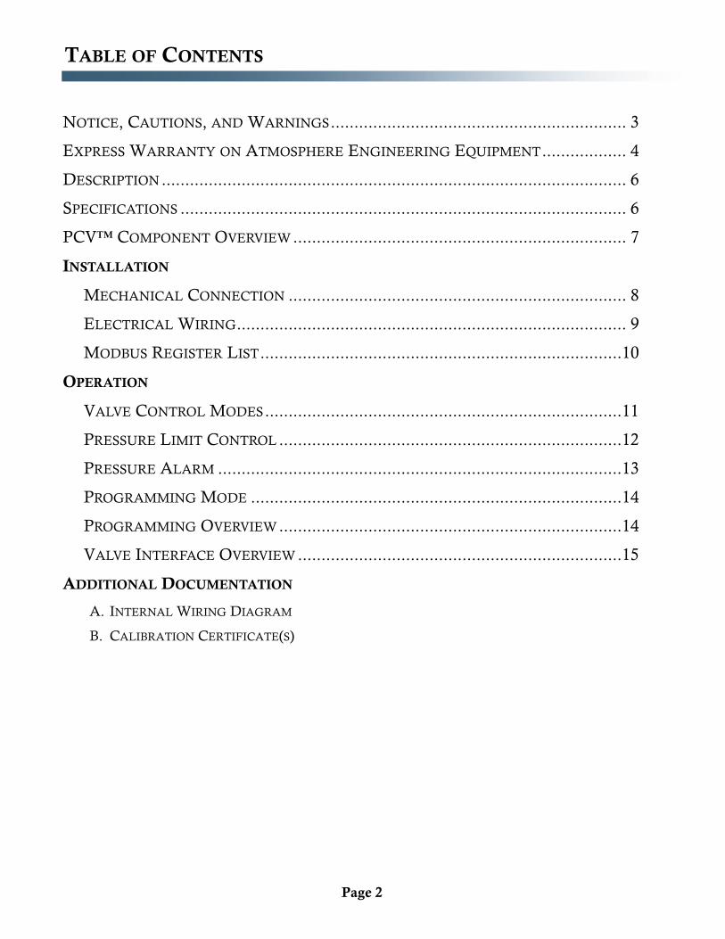
TABLE OF CONTENTS
NOTICE, CAUTIONS, AND WARNINGS ............................................................... 3
EXPRESS WARRANTY ON ATMOSPHERE ENGINEERING EQUIPMENT .................. 4
DESCRIPTION ................................................................................................... 6
SPECIFICATIONS ............................................................................................... 6
PCV™ COMPONENT OVERVIEW ....................................................................... 7
INSTALLATION
MECHANICAL CONNECTION ........................................................................ 8
ELECTRICAL WIRING ................................................................................... 9
MODBUS REGISTER LIST ............................................................................. 10
OPERATION
VALVE CONTROL MODES ............................................................................ 11
PRESSURE LIMIT CONTROL ......................................................................... 12
PRESSURE ALARM ...................................................................................... 13
PROGRAMMING MODE ............................................................................... 14
PROGRAMMING OVERVIEW ......................................................................... 14
VALVE INTERFACE OVERVIEW ..................................................................... 15
ADDITIONAL DOCUMENTATION
A. INTERNAL WIRING DIAGRAM
B. CALIBRATION CERTIFICATE(S)
Page 3
NOTICE
This Bulletin contains important safety information and should be read and understood by all individuals who install, use, or service this equipment.
Failure to follow the precautions and recommendations of this manual may subject per-sonnel and property to dangerous conditions.
WARNING The valves used for flow control do not provide positive gas shut off. Valve may leak
and cause asphyxiation or poisoning to personnel within confined spaces.
It is always recommended that users install appropriate lockable gas shut off valves for
positive gas shut off.
TECHNICAL ASSISTANCE
Contact Atmosphere Engineering Company with any questions or concerns regarding the installation, operation, or setup of the FurnaceMeter ™ mixing system.
Phone: 414-331-2457 Fax: 414-332-2457 E-Mail: [email protected]
NOTICE, CAUTIONS, AND WARNINGS
Page 4
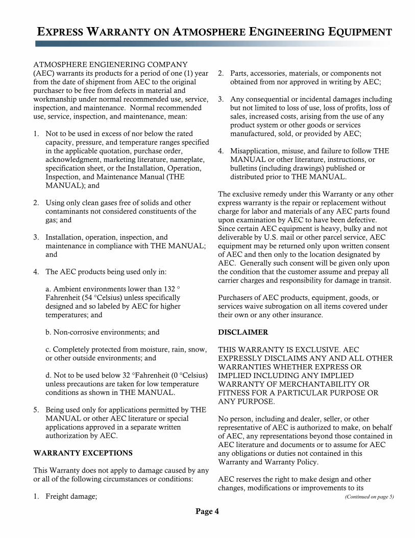
ATMOSPHERE ENGIENERING COMPANY (AEC) warrants its products for a period of one (1) year from the date of shipment from AEC to the original purchaser to be free from defects in material and workmanship under normal recommended use, service, inspection, and maintenance. Normal recommended use, service, inspection, and maintenance, mean: 1. Not to be used in excess of nor below the rated
capacity, pressure, and temperature ranges specified in the applicable quotation, purchase order, acknowledgment, marketing literature, nameplate, specification sheet, or the Installation, Operation, Inspection, and Maintenance Manual (THE MANUAL); and
2. Using only clean gases free of solids and other contaminants not considered constituents of the gas; and
3. Installation, operation, inspection, and maintenance in compliance with THE MANUAL; and
4. The AEC products being used only in: a. Ambient environments lower than 132 °Fahrenheit (54 °Celsius) unless specifically designed and so labeled by AEC for higher temperatures; and b. Non-corrosive environments; and c. Completely protected from moisture, rain, snow, or other outside environments; and d. Not to be used below 32 °Fahrenheit (0 °Celsius) unless precautions are taken for low temperature conditions as shown in THE MANUAL.
5. Being used only for applications permitted by THE MANUAL or other AEC literature or special applications approved in a separate written authorization by AEC.
WARRANTY EXCEPTIONS This Warranty does not apply to damage caused by any or all of the following circumstances or conditions: 1. Freight damage;
2. Parts, accessories, materials, or components not
obtained from nor approved in writing by AEC;
3. Any consequential or incidental damages including but not limited to loss of use, loss of profits, loss of sales, increased costs, arising from the use of any product system or other goods or services manufactured, sold, or provided by AEC;
4. Misapplication, misuse, and failure to follow THE MANUAL or other literature, instructions, or bulletins (including drawings) published or distributed prior to THE MANUAL.
The exclusive remedy under this Warranty or any other express warranty is the repair or replacement without charge for labor and materials of any AEC parts found upon examination by AEC to have been defective. Since certain AEC equipment is heavy, bulky and not deliverable by U.S. mail or other parcel service, AEC equipment may be returned only upon written consent of AEC and then only to the location designated by AEC. Generally such consent will be given only upon the condition that the customer assume and prepay all carrier charges and responsibility for damage in transit. Purchasers of AEC products, equipment, goods, or services waive subrogation on all items covered under their own or any other insurance.
DISCLAIMER
THIS WARRANTY IS EXCLUSIVE. AEC EXPRESSLY DISCLAIMS ANY AND ALL OTHER WARRANTIES WHETHER EXPRESS OR IMPLIED INCLUDING ANY IMPLIED WARRANTY OF MERCHANTABILITY OR FITNESS FOR A PARTICULAR PURPOSE OR ANY PURPOSE. No person, including and dealer, seller, or other representative of AEC is authorized to make, on behalf of AEC, any representations beyond those contained in AEC literature and documents or to assume for AEC any obligations or duties not contained in this Warranty and Warranty Policy. AEC reserves the right to make design and other changes, modifications or improvements to its
(Continued on page 5)
EXPRESS WARRANTY ON ATMOSPHERE ENGINEERING EQUIPMENT
Page 5
products, services, literature, or systems, without any obligation, to furnish or install same on any previously sold or delivered products or systems.
LIMITATION OF LIABILITY It is expressly agreed that the liability of AEC is limited and AEC does not function as an insurer. The purchaser and/or user agree that AEC is not liable for loss, harm, or damage due directly or indirectly to any occurrence or consequences there from. If AEC should be found liable to anyone on any theory (except any express warranty where the remedy is set forth in Section 2 of this Warranty and Warranty Policy) for loss harm or damage, the liability of AEC shall be limited to the lesser of the actual loss, harm or damage or the purchase price of the involved AEC equipment or service when sold (or when service performed) by AEC to its customer. This liability is exclusive and regardless of cause or origin resulting directly or indirectly to any person or property from: 1. The performance or nonperformance of any
obligations set forth in this Warranty and Warranty Policy;
2. Any agreement including specifications between AEC and the customer;
3. Negligence, active, passive or otherwise of AEC or any of its agents or employees;
4. Breach of any judicially imposed warranty or covenant of workmanship, durability or performance; and
5. Misrepresentation (under the Restatement, common law or otherwise) and/or strict liability involvement;
6. Liability for fraud-in-the-inducement.
WARRANTY FIELD SERVICE
If warranty Field Service at the request of the purchaser or user is rendered and the difficulty is found not to be with AEC’s product, the purchaser shall pay the time and expense (at the prevailing rate at the time of the service) of AEC’s field representative(s). Charges for service, labor, and other expenses that have been incurred by the purchaser, its customer or agent without written approval of AEC will not be accepted. The OEM or other reseller is responsible for transmitting installation and operating instructions, THE MANUAL or other service literature supplied by AEC with the equipment.
(Continued from page 4)
EXPRESS WARRANTY ON ATMOSPHERE ENGINEERING EQUIPMENT
Page 6
DESCRIPTION
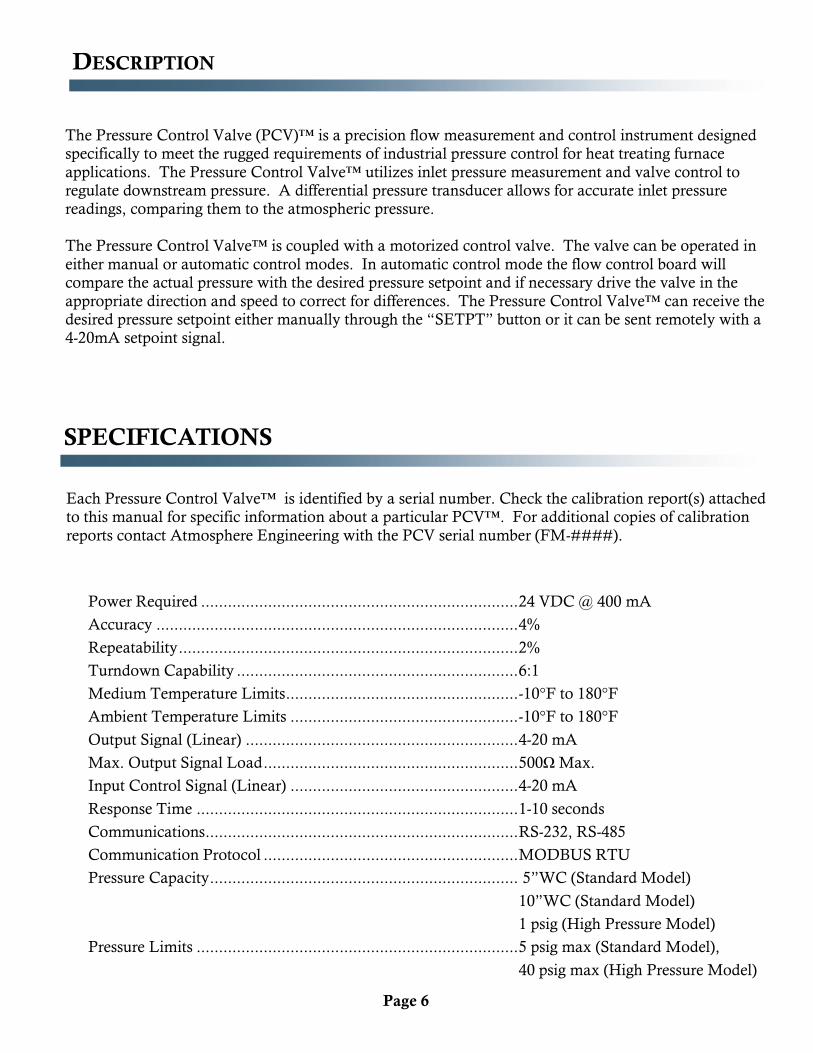
The Pressure Control Valve (PCV)™ is a precision flow measurement and control instrument designed specifically to meet the rugged requirements of industrial pressure control for heat treating furnace
applications. The Pressure Control Valve™ utilizes inlet pressure measurement and valve control to regulate downstream pressure. A differential pressure transducer allows for accurate inlet pressure readings, comparing them to the atmospheric pressure.
The Pressure Control Valve™ is coupled with a motorized control valve. The valve can be operated in
either manual or automatic control modes. In automatic control mode the flow control board will compare the actual pressure with the desired pressure setpoint and if necessary drive the valve in the
appropriate direction and speed to correct for differences. The Pressure Control Valve™ can receive the desired pressure setpoint either manually through the “SETPT” button or it can be sent remotely with a 4-20mA setpoint signal.
SPECIFICATIONS
Power Required ....................................................................... 24 VDC @ 400 mA
Accuracy ................................................................................. 4%
Repeatability ............................................................................ 2%
Turndown Capability ............................................................... 6:1
Medium Temperature Limits .................................................... -10°F to 180°F
Ambient Temperature Limits ................................................... -10°F to 180°F
Output Signal (Linear) ............................................................. 4-20 mA
Max. Output Signal Load ......................................................... 500Ω Max.
Input Control Signal (Linear) ................................................... 4-20 mA
Response Time ........................................................................ 1-10 seconds
Communications ...................................................................... RS-232, RS-485
Communication Protocol ......................................................... MODBUS RTU
Pressure Capacity ..................................................................... 5”WC (Standard Model)
10”WC (Standard Model)
1 psig (High Pressure Model)
Pressure Limits ........................................................................ 5 psig max (Standard Model),
40 psig max (High Pressure Model)
Each Pressure Control Valve™ is identified by a serial number. Check the calibration report(s) attached to this manual for specific information about a particular PCV™. For additional copies of calibration
reports contact Atmosphere Engineering with the PCV serial number (FM-####).
Page 7
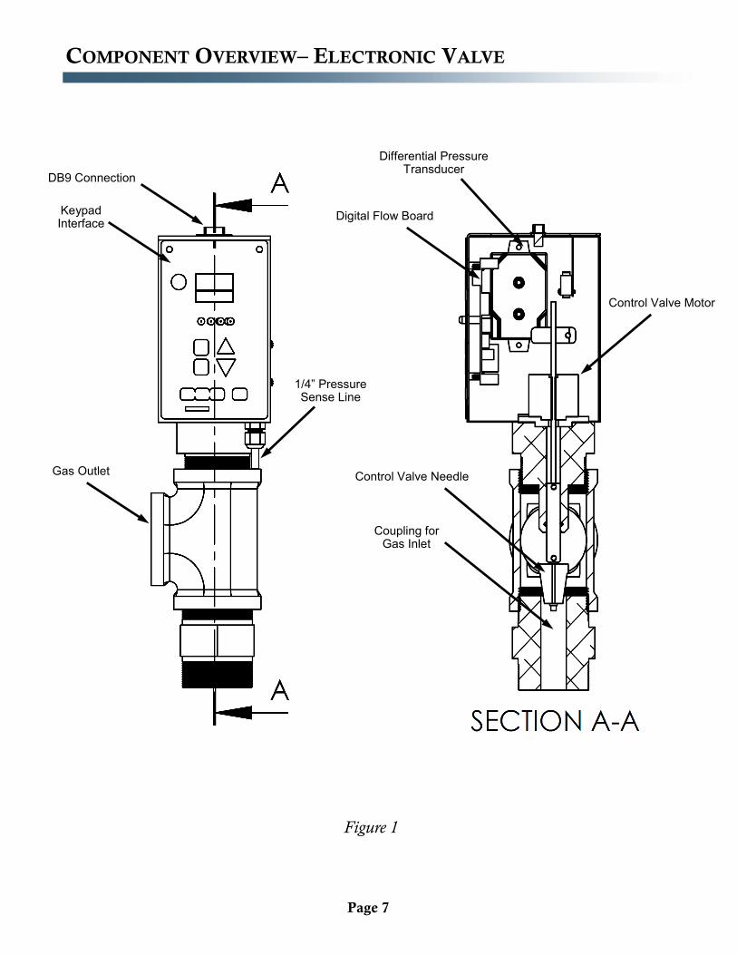
COMPONENT OVERVIEW– ELECTRONIC VALVE
Figure 1
DB9 Connection
Keypad Interface
Gas Outlet
1/4” Pressure Sense Line
Differential Pressure Transducer
Digital Flow Board
Control Valve Motor
Control Valve Needle
Coupling for Gas Inlet
Page 8
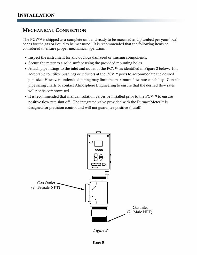
INSTALLATION
The PCV™ is shipped as a complete unit and ready to be mounted and plumbed per your local codes for the gas or liquid to be measured. It is recommended that the following items be
considered to ensure proper mechanical operation.
Inspect the instrument for any obvious damaged or missing components.
Secure the meter to a solid surface using the provided mounting holes.
Attach pipe fittings to the inlet and outlet of the PCV™ as identified in Figure 2 below. It is
acceptable to utilize bushings or reducers at the PCV™ ports to accommodate the desired
pipe size. However, undersized piping may limit the maximum flow rate capability. Consult
pipe sizing charts or contact Atmosphere Engineering to ensure that the desired flow rates
will not be compromised.
It is recommended that manual isolation valves be installed prior to the PCV™ to ensure
positive flow rate shut off. The integrated valve provided with the FurnaceMeter™ is
designed for precision control and will not guarantee positive shutoff.
MECHANICAL CONNECTION
Figure 2
Gas Outlet (2” Female NPT)
Gas Inlet (2” Male NPT)
Page 9
INSTALLATION
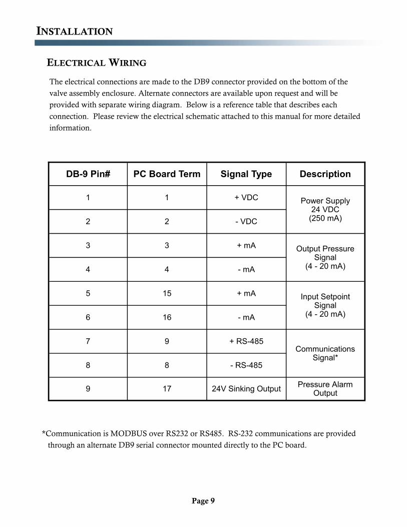
ELECTRICAL WIRING
The electrical connections are made to the DB9 connector provided on the bottom of the
valve assembly enclosure. Alternate connectors are available upon request and will be
provided with separate wiring diagram. Below is a reference table that describes each
connection. Please review the electrical schematic attached to this manual for more detailed
information.
*Communication is MODBUS over RS232 or RS485. RS-232 communications are provided
through an alternate DB9 serial connector mounted directly to the PC board.
DB-9 Pin# PC Board Term Signal Type Description
1 1 + VDC Power Supply 24 VDC
(250 mA) 2 2 - VDC
3 3 + mA Output Pressure Signal
(4 - 20 mA) 4 4 - mA
5 15 + mA Input Setpoint Signal
(4 - 20 mA) 6 16 - mA
7 9 + RS-485 Communications
Signal* 8 8 - RS-485
9 17 24V Sinking Output Pressure Alarm
Output
Page 10
INSTALLATION
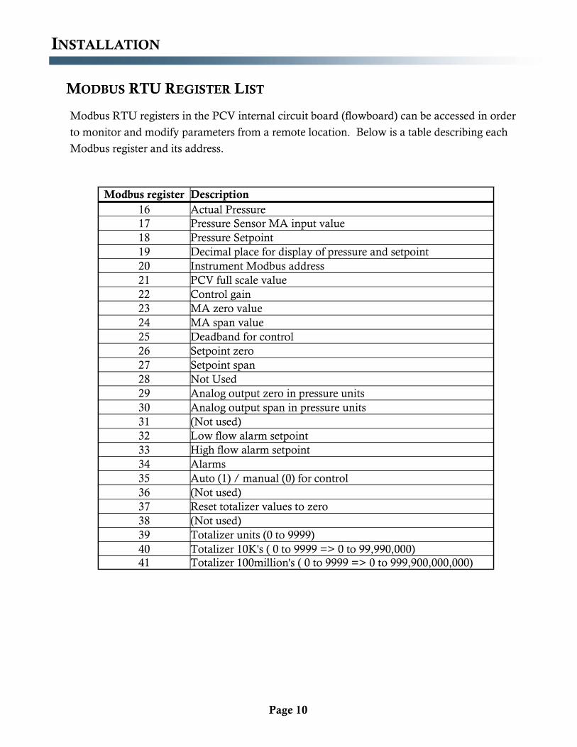
MODBUS RTU REGISTER LIST
Modbus RTU registers in the PCV internal circuit board (flowboard) can be accessed in order
to monitor and modify parameters from a remote location. Below is a table describing each
Modbus register and its address.
Modbus register Description
16 Actual Pressure
17 Pressure Sensor MA input value
18 Pressure Setpoint
19 Decimal place for display of pressure and setpoint
20 Instrument Modbus address
21 PCV full scale value
22 Control gain
23 MA zero value
24 MA span value
25 Deadband for control
26 Setpoint zero
27 Setpoint span
28 Not Used
29 Analog output zero in pressure units
30 Analog output span in pressure units
31 (Not used)
32 Low flow alarm setpoint
33 High flow alarm setpoint
34 Alarms
35 Auto (1) / manual (0) for control
36 (Not used)
37 Reset totalizer values to zero
38 (Not used)
39 Totalizer units (0 to 9999)
40 Totalizer 10K's ( 0 to 9999 => 0 to 99,990,000)
41 Totalizer 100million's ( 0 to 9999 => 0 to 999,900,000,000)
Page 11
OPERATION
The PCV is a differential pressure flow meter that utilizes a custom built calibration and control board assembly designed specifically for furnace atmosphere control systems. The calibration and control
board assembly has an integrated high and low pressure alarm and an integrated valve control capability that can be operated in either manual or automatic pressure control modes.
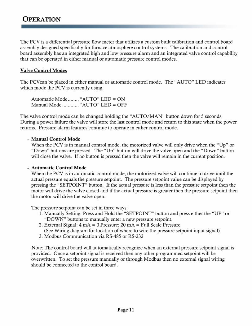
Valve Control Modes
The PCVcan be placed in either manual or automatic control mode. The “AUTO” LED indicates
which mode the PCV is currently using.
Automatic Mode ........ “AUTO” LED = ON
Manual Mode ............ “AUTO” LED = OFF
The valve control mode can be changed holding the “AUTO/MAN” button down for 5 seconds. During a power failure the valve will store the last control mode and return to this state when the power
returns. Pressure alarm features continue to operate in either control mode.
Manual Control Mode
When the PCV is in manual control mode, the motorized valve will only drive when the “Up” or “Down” buttons are pressed. The “Up” button will drive the valve open and the “Down” button will close the valve. If no button is pressed then the valve will remain in the current position.
Automatic Control Mode
When the PCV is in automatic control mode, the motorized valve will continue to drive until the
actual pressure equals the pressure setpoint. The pressure setpoint value can be displayed by pressing the “SETPOINT” button. If the actual pressure is less than the pressure setpoint then the
motor will drive the valve closed and if the actual pressure is greater then the pressure setpoint then the motor will drive the valve open.
The pressure setpoint can be set in three ways:
1. Manually Setting: Press and Hold the “SETPOINT” button and press either the “UP” or
“DOWN” buttons to manually enter a new pressure setpoint. 2. External Signal: 4 mA = 0 Pressure; 20 mA = Full Scale Pressure
(See Wiring diagram for location of where to wire the pressure setpoint input signal) 3. Modbus Communication via RS-485 or RS-232
Note: The control board will automatically recognize when an external pressure setpoint signal is provided. Once a setpoint signal is received then any other programmed setpoint will be
overwritten. To set the pressure manually or through Modbus then no external signal wiring should be connected to the control board.
Page 12
OPERATION
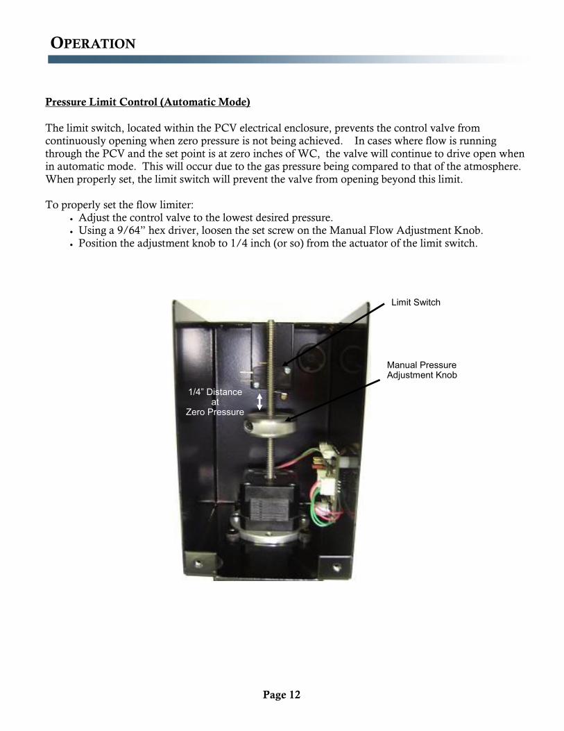
Pressure Limit Control (Automatic Mode)
The limit switch, located within the PCV electrical enclosure, prevents the control valve from continuously opening when zero pressure is not being achieved. In cases where flow is running
through the PCV and the set point is at zero inches of WC, the valve will continue to drive open when in automatic mode. This will occur due to the gas pressure being compared to that of the atmosphere.
When properly set, the limit switch will prevent the valve from opening beyond this limit.
To properly set the flow limiter: Adjust the control valve to the lowest desired pressure.
Using a 9/64” hex driver, loosen the set screw on the Manual Flow Adjustment Knob.
Position the adjustment knob to 1/4 inch (or so) from the actuator of the limit switch.
Manual Pressure Adjustment Knob 1/4
Limit Switch
1/4” Distance at
Zero Pressure
Page 13
OPERATION
Pressure Alarm
The PCV is provided with a pressure alarm output that can be used to trigger a relay. When in non-
alarm state, the relay coil will be energized. Conversely, in the alarm state the relay will be de-energized. A normally open contact could then be used to power an alarm horn. Proper wiring of
the alarm output is detailed on the attached wiring diagram. The “ALARM” LED indicates when the flow rate is outside the desired range.
Pressure Alarm ON …..“ALARM” LED = ON Pressure Alarm OK …. “ALARM” LED = OFF
The pressure alarm is on when either the actual pressure is greater than the “High Pressure Alarm
Setpoint” or the actual pressure is less than the “Low Pressure Alarm Setpoint”. The alarm is not latching. The pressure alarm set points can be set either through Modbus communications or by using the PCV Configuration Software available on the Atmosphere Engineering website.
Note: As a default, the PCV comes preprogrammed with the high and low alarm set points set
outside the scale range of the PCV. This setting essentially deactivates the pressure alarm since the pressure will never trigger an alarm event.
Page 14
OPERATION
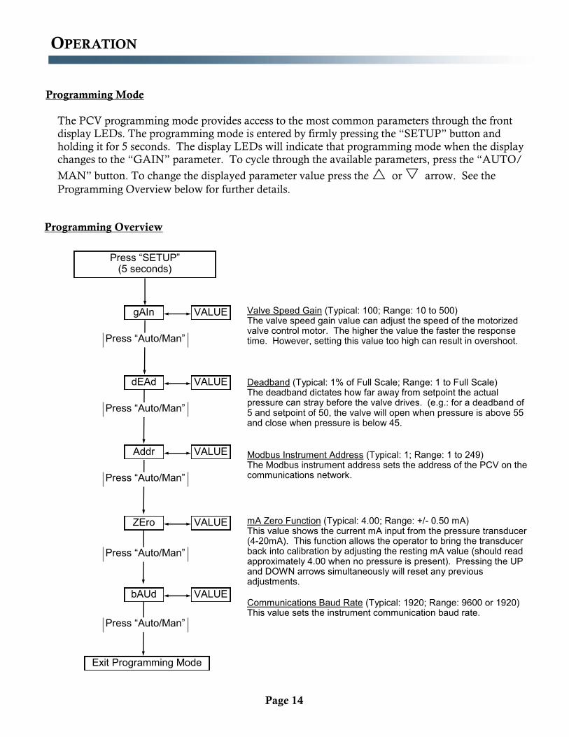
Programming Mode
The PCV programming mode provides access to the most common parameters through the front
display LEDs. The programming mode is entered by firmly pressing the “SETUP” button and holding it for 5 seconds. The display LEDs will indicate that programming mode when the display
changes to the “GAIN” parameter. To cycle through the available parameters, press the “AUTO/
MAN” button. To change the displayed parameter value press the or arrow. See the
Programming Overview below for further details.
Programming Overview
Press “SETUP” (5 seconds)
gAIn VALUE
dEAd VALUE
Press “Auto/Man”
Press “Auto/Man”
Addr VALUE
bAUd VALUE
Press “Auto/Man”
Exit Programming Mode
Press “Auto/Man”
Valve Speed Gain (Typical: 100; Range: 10 to 500) The valve speed gain value can adjust the speed of the motorized valve control motor. The higher the value the faster the response time. However, setting this value too high can result in overshoot.
Modbus Instrument Address (Typical: 1; Range: 1 to 249) The Modbus instrument address sets the address of the PCV on the communications network.
Communications Baud Rate (Typical: 1920; Range: 9600 or 1920) This value sets the instrument communication baud rate.
Deadband (Typical: 1% of Full Scale; Range: 1 to Full Scale) The deadband dictates how far away from setpoint the actual pressure can stray before the valve drives. (e.g.: for a deadband of 5 and setpoint of 50, the valve will open when pressure is above 55 and close when pressure is below 45.
ZEro VALUE
Press “Auto/Man”
mA Zero Function (Typical: 4.00; Range: +/- 0.50 mA) This value shows the current mA input from the pressure transducer (4-20mA). This function allows the operator to bring the transducer back into calibration by adjusting the resting mA value (should read approximately 4.00 when no pressure is present). Pressing the UP and DOWN arrows simultaneously will reset any previous adjustments.
Page 15
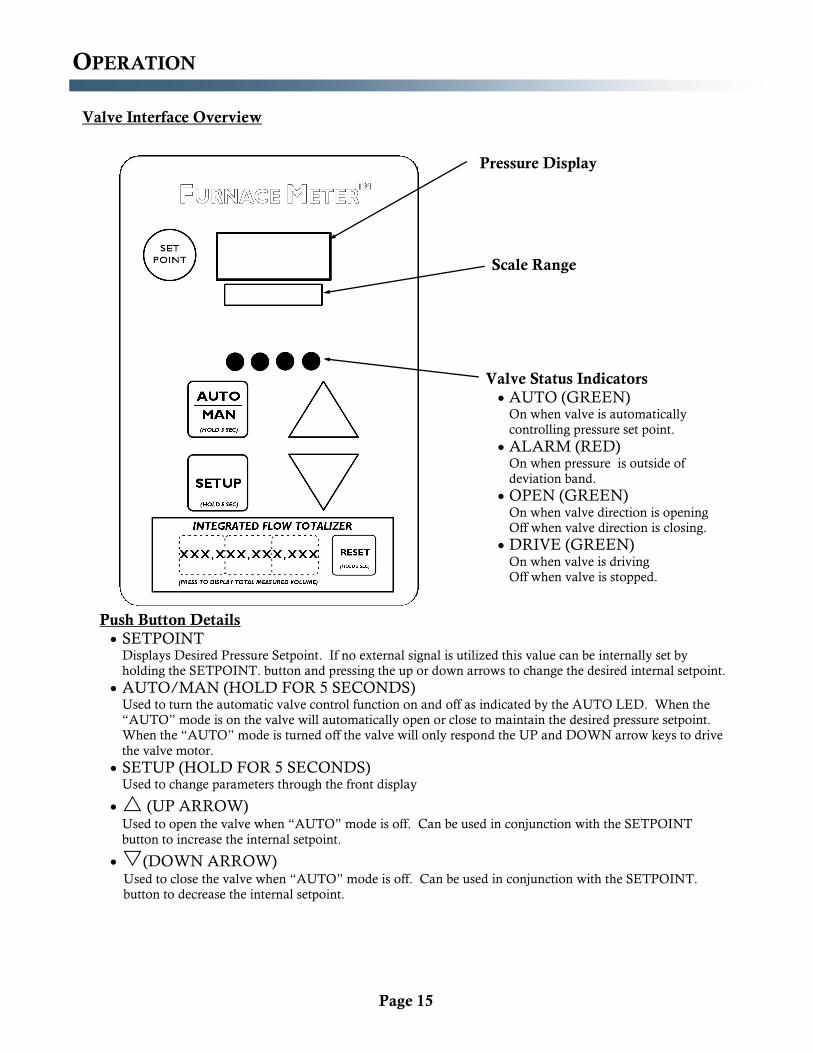
Valve Interface Overview
AUTO ALM V1 V2
TOTAL SETPT. AUTO
Pressure Display
Valve Status Indicators
AUTO (GREEN) On when valve is automatically
controlling pressure set point. ALARM (RED)
On when pressure is outside of
deviation band. OPEN (GREEN)
On when valve direction is opening
Off when valve direction is closing. DRIVE (GREEN)
On when valve is driving
Off when valve is stopped.
Push Button Details
SETPOINT Displays Desired Pressure Setpoint. If no external signal is utilized this value can be internally set by
holding the SETPOINT. button and pressing the up or down arrows to change the desired internal setpoint. AUTO/MAN (HOLD FOR 5 SECONDS)
Used to turn the automatic valve control function on and off as indicated by the AUTO LED. When the
“AUTO” mode is on the valve will automatically open or close to maintain the desired pressure setpoint.
When the “AUTO” mode is turned off the valve will only respond the UP and DOWN arrow keys to drive
the valve motor. SETUP (HOLD FOR 5 SECONDS)
Used to change parameters through the front display
(UP ARROW) Used to open the valve when “AUTO” mode is off. Can be used in conjunction with the SETPOINT
button to increase the internal setpoint.
(DOWN ARROW) Used to close the valve when “AUTO” mode is off. Can be used in conjunction with the SETPOINT.
button to decrease the internal setpoint.
OPERATION
Scale Range
Page 16
ADDITIONAL DOCUMENTATION
Internal Wiring Drawing
PCV Calibration Curve