Document # 3780 REVISION A TOYOTA RAV4 2006 INTERIOR …
11
Color Applicability/Trim Level Accessory Color General Applicability All models of Rav-4 Recommended Sequence of Application Item # Accessory 1 * Overlay Apply any overlay first 2 3 *Mandatory Kit Contents Item # Quantity Reqd. Description 1 2 13” Light Rod 2 1 Wire harness 3 1 Hardware Kit 4 2 White Light Engines 5 1 Switch Kit 6 2 Amber cup holder kits 7 1 Customer Information card 8 1 Die Cut Adhesive 9 1 “Y” Adapter Hardware Bag Contents Item # Quantity Reqd. Description 1 4 Catamount 2 4 8-32 x .375 screw 3 4 “U” nut 4 4 Wire tie .187 5 4 Wire tie .0625 6 6 foam pads 7 2 T-Taps Switch Bag Contents Item # Quantity Reqd. Description 1 1 Switch 2 1 End Cap, Black 3 1 Illumination Nameplate 4 1 Installation tool 5 1 Bezel 6 1 Black spacer Recommended tools Safety Tools Vehicle protection Safety glasses Special Tools Installation Tools Phillips screwdriver #2 Torque wrench 36 in. lbs. Nylon Removal Tool Pliers Diagonal cutter or wire tie tool Stubby screwdriver #2 Phillips Drill motor Scissors 1/2” Drill bit. UniBit or step drill rec. 1/8” Drill bit Scribe or Center punch Masking tape Panel clip tool 9/32” Drill bit Wiping cloth Non-scratch Special Chemicals Window cleaner Section I - Installation Preparation 1 of 10 Document # 3780 REVISION A12/19/05 TOYOTA RAV4 2006 INTERIOR LIGHT UPGRADE Part Number: 00016-00060 Code: IL1 SPECIAL NOTE: Installation Sequences After TMS and Safety mandated preparatory steps have been taken, the installation sequence is the suggested method for completing the accessory installation. In some instances the suggested sequence is written for one associate to install and in others the sequence is given as part of a team accessory installation. Unless otherwise stated in the document, the associates may perform the installation steps in any order to make the installation as efficient as possible while maintaining consistent quality. Also some items listed to be removed may not need to be removed if caution is taken to not damage vehicle. *Mandatory Legend Legend
Transcript of Document # 3780 REVISION A TOYOTA RAV4 2006 INTERIOR …

Section II - Installation Procedures
Color Applicability/Trim Level
AccessoryC
olor
General ApplicabilityAll models of Rav-4
Recommended Sequence of ApplicationItem # Accessory1 * Overlay Apply any overlay first2
3
*Mandatory
Kit ContentsItem # Quantity Reqd. Description1 2 13” Light Rod2 1 Wire harness3 1 Hardware Kit4 2 White Light Engines5 1 Switch Kit
6 2 Amber cup holder kits7 1 Customer Information card8 1 Die Cut Adhesive9 1 “Y” Adapter
Hardware Bag ContentsItem # Quantity Reqd. Description1 4 Catamount
2 4 8-32 x .375 screw
3 4 “U” nut
4 4 Wire tie .187
5 4 Wire tie .0625
6 6 foam pads
7 2 T-Taps
Switch Bag ContentsItem # Quantity Reqd. Description1 1 Switch
2 1 End Cap, Black
3 1 Illumination Nameplate
4 1 Installation tool
5 1 Bezel
6 1 Black spacer
Recommended toolsSafety ToolsVehicle protectionSafety glassesSpecial ToolsInstallation ToolsPhillips screwdriver #2Torque wrench 36 in. lbs.Nylon Removal ToolPliersDiagonal cutter or wire tie toolStubby screwdriver #2 PhillipsDrill motorScissors1/2” Drill bit. UniBit or step drill rec.1/8” Drill bitScribe or Center punchMasking tapePanel clip tool9/32” Drill bitWiping cloth Non-scratchSpecial ChemicalsWindow cleaner
Section I - Installation Preparation
1 of 10
Document # 3780 REVISION A 12/19/05
TOYOTA RAV4 2006 INTERIOR LIGHT UPGRADE
Part Number: 00016-00060Code: IL1
SPECIAL NOTE: Installation Sequences
After TMS and Safety mandated preparatory steps have been taken, the installation sequence is the suggested method for completing the accessory installation. In some instances the suggested sequence is written for one associate to install and in others the sequence is given as part of a team accessory installation. Unless otherwise stated in the document, the associates may perform the installation steps in any order to make the installation as efficient as possible while maintaining consistent quality. Also some items listed to be removed may not need to be removed if caution is taken to not damage vehicle.
*Mandatory
Legend
Legend

TOYOTA RAV4 2006 INTERIOR LIGHT UPGRADESection II - Installation Procedures
A.Checkkitforcontents1. Check kit of content and damage.
(Fig. A1)
B.Vehiclepreparation1.
Disconnect battery negative terminal.2.
Apply protective covering to car.
C.Removecenterconsole1. Remove upper console garnish.
i. Use panel safe tool.
ii. Carefully pry around lower edge of garnish. (Fig. C1)
iii. Firmly lift garnish straight up.
iv. Repeat on other side. (Fig. C2)
2. Remove upper console panel sub-assembly
i. Remove shift lever knob, turn counter clockwise. (Fig. C3)
ii. Using panel safe tool, pry around edges of upper console panel. (Fig. C4)
iii. Disconnect connector. (Fig. C5)
3. Remove switch base.
i. Use panel safe tool.
ii. Pry around lower corner of switch base. (Fig. C6)
iii. Disconnect connectors. (Fig. C7)
4. Remove console cup holder assembly.
i. Remove (2) screws. (Fig. C8)
ii. Using panel safe tool pry up both forward edges and remove. (Fig. C9)
Fig. A1
Harness
LED Modules
Switch
Light Guide
Cup Holder
Hardware Kit
2 of 10
Fig. C1 Fig. C2
Fig. C3 Fig. C4
Fig. C5
Fig. C6 Fig. C7
Fig. C8 Fig. C9

TOYOTA RAV4 2006 INTERIOR LIGHT UPGRADESection II - Installation Procedures
3 of 10
5. Remove upper rear console panel sub-assembly.
i. Using panel safe tool, Pry around edges of panel. (Fig. C10)
ii. Disconnect connectors. (Fig. C11)
6. Remove console rear end panel.
i. Using panel safe tool, pry around edges and pull straight back. (Fig. C12)
7. Remove instrument panel bracket cover.
i. Using panel safe tool detach claws and remove. (Fig. C13)
ii. Repeat for other side. (Fig. C14)
8. Remove console sub-assembly.
i Remove console box liner. (Fig. C15)
ii. Remove (2) screws. (Fig. C16)
iii Remove (2) 10mm bolts. (Fig. C17)
iv. Disconnect the connector and remove the rear console box. (Fig. C18)
Fig. C10 Fig. C11
Fig. C12a Fig. C12b
Fig. C13 Fig. C14
Fig. C15
Fig. C17 Fig. C18
Fig. C16
TOYOTA RAV4 2006 INTERIOR LIGHT UPGRADESection II - Installation Procedures
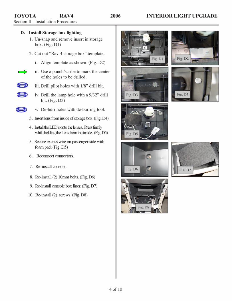
3. Insert lens from inside of storage box. (Fig. D4)
4. Install the LED’s onto the lenses. Press firmly while holding the Lens from the inside. (Fig. D5)
5. Secure excess wire on passenger side with foam pad. (Fig. D5)
6.
7. Re-install console.
8. Re-install (2) 10mm bolts. (Fig. D6)
9. Re-install console box liner. (Fig. D7)
10. Re-install (2) screws. (Fig. D8)
Reconnect connectors.
4 of 10
D. InstallStorageboxlighting1. Un-snap and remove insert in storage
box. (Fig. D1)
2. Cut out “Rav-4 storage box” template.
i. Align template as shown. (Fig. D2)
ii. Use a punch/scribe to mark the center of the holes to be drilled.
iii. Drill pilot holes with 1/8” drill bit.
iv. Drill the lamp hole with a 9/32” drill bit. (Fig. D3)
v. De-burr holes with de-burring tool.
Fig. D1 Fig. D2
Fig. D3 Fig. D4
Fig. D5
Fig. D6 Fig. D7
Fig. D8

TOYOTA RAV4 2006 INTERIOR LIGHT UPGRADESection II - Installation Procedures
E.InstallCupHolderLights1. Cut out template labeled “cup holder”.
2. Attach template to cup holder with adhesive tape.
i. Make sure LEDs are inserted from “flap side of cup holder
ii . Use punch or scribe to mark where to drill. (Fig E1)
3. Drill Lamp hole.
i. Drill pilot holes with 1/8” drill bit.
ii. Drill the lamp hole with a letter “9/32” drill bit. (Fig. E2)
iii. De-burr holes with de-burring tool.
4. Insert lens from inside of cup holder. (Fig. E3)
5. Firmly press LED assembly into lens. (Fig. E4)
6. Use adhesive pad to secure wires. (Fig. E4)
5 of 10
Fig.E1 Fig. E2
Fig. E3 Fig. E4
F.LocatePower1. Locate leads going to front power outlet
socket.
2. Attach T-taps as shown. (Fig. F1)
G.InstallMainHarness1. Distribute harness as shown. (Fig. H1)
i. PW-Power, two male spade connec-tors.
ii. SW-Switch, Three female spade con-nectors.
iii. CH-Cup Holder, female modular con-nector.
iv. LED-LED Module, (2) female modular connectors.
Fig. F1
Front auxillary powerConnector E43
Ground: Pin # 2 White/Black
1 2
E43
Power: Pin # 1 White
cvjcram
Fig. F1 Front auxillary power Connector E43 Ground: Pin # 2 White/Black 1 2 E43 Power: Pin # 1 White
cvjcram
cvjcram

TOYOTA RAV4 2006 INTERIOR LIGHT UPGRADESection II - Installation Procedures
6 of 10
2. Route leads.i. Lay harness in lower half of center
console.ii. Route power leads to the auxiliary
power outlet tapped earlier.
iii. Route LED module leads forward to left and right side of center.
iv. Route switch lead so it will be acces-sible through center dash bezel.
H.InstallLightGuide1. Install passenger side light guide.
i. Remove under-dash shield, depress tabs drop and slide forward. (Fig. H1)
ii. Drill holes in location shown. (Fig. H2)
iii. Attach LED module to light guide and orient White stripe towards top.
iv. Secure light guide to shield with cable ties, remove excess
v. Reinstall under-dash shield.
2. Attach LED module lead to harness. (Fig. H3)
3. Re-install instrument panel bracket cover. (Fig. H4)
4. Install Driver Side Light Guide.
i. Attach catamount to “U” nut.
ii. Locate right “U” nut, Attach to interior edge of air duct. (Fig. H5)
iii. Locate left “U” nut, and attach to plastic tab as shown. (Fig. H6)
iv. Attach LED module to light guide.
v. Secure light guide to catamounts with plastic tie. (Fig. H7 & H8)
vi. Orient light guide with white stripe towards the top.
Fig. H1 Fig. H2
Fig. H3 Fig. H4
Fig. H5 Fig. H6
Fig. H 7 Fig. H 8
NOTE: White harness wire attaches to white wire
wire in Connector E 43
in Connector E 43 Black harness wire attaches to white/black
cvjcram
White harness wire attaches to white wire wire in Connector E 43 in Connector E 43 Black harness wire attaches to white/black

TOYOTA RAV4 2006 INTERIOR LIGHT UPGRADESection II - Installation Procedures
5. Attach LED module lead to harness. (Fig. H9)
6. Re-install instrument panel bracket cover. (Fig. H10)
Fig. H9 Fig. H10
I. InstallSwitchAssembly1. Remove knock out from switch panel.
(Fig. I1)
2. Drill 1/2” hole 1/2” from top of knock out and center left to right. Use diagonal cutters to remove ribs. (Fig. I2)
4. Insert switch bezel into switch plate and remove
5. Using the bezel as a guide, install switch plate/bezel into the previously drilled 1/2” hole.
i. Align the printing “ILLUMINA-TION” square to the console. (Fig. I4)
6. Install Sleeve to bezel.
i. The “white” ink end of the sleeve must be installed against the console. (Fig. I5)
7. Install switch to bezel as shown. (Fig. I6)
i. Turn switch clockwise to tighten.
ii. Be careful not to over tighten as this will “over ride” the threads on the switch. If this happens simply retighten being careful not to over tighten.
iii. Push button into bezel pressing to engage.
8. Attach switch leads to harness, re-install knock out panel. (Fig. I7)
Fig. I1 Fig. I2
Fig. I3 Fig. I4
Fig. I5 Fig. I6
Fig. I7
7 of 10
NOTE: If overlay applied remove 1/8” of blackend of sleeve with sandpaper
3. Clean surface at switch plate location.
tape liner. (Fig. I3)
(A to A, B to B, & C to C)

TOYOTA RAV4 2006 INTERIOR LIGHT UPGRADESection II - Installation Procedures
8 of 10
J.Re-installcenterconsole.
1. Connect cup holder LEDS to harness. (Fig. J1)
2. Re-install cup holder assembly
i. Secure front tabs.
ii. Re-install (2) screws
3. Re-install shift surround
4 Re-install console garnish
5. Re-install shift knob.
Fig. J7

TOYOTA RAV4 2006 INTERIOR LIGHT UPGRADESection II - Installation Procedures
M.PostInstallation1. Reinstall interior.
2. Re-attach negative battery terminal, torque to 36 inch pounds.
3. Clean Light Guides with window cleaner and a non-scratch cloth.
4. Cycle test the system with the key in the ACC or ON position. The cycle may start from any step below but should cycle in this order.
i. All lights off.
ii. Cup holder lights on only.
iii. All lights on.
iv. Interior Light on only.
v. Back to step “i”.
5. The switch should be cycled to step “i” (all lights off) for shipment.
6. Place information card in glove box.
9 of 10

TOYOTA RAV4 2006 INTERIOR LIGHT UPGRADESection II - Installation Procedures
Section III Functional verification
Check:
___________________________________
Single Unoperational Module
No Operational Modules
Look for:
___________________________________
Full engagement of affected LED module to LED wire harness pigtail connector.
Light guide inserted incorrectly (wrong end)
Full engagement of all LED module to LED wire harness pigtail connectors.
Power connection.
Ground connection
Switch connections
Blown light kit fuse. (2 amp located under center console)
Blown shift console illumination fuse (see vehi-cle owners manual for amperage and location.)
10 of 10
VEHICLE FUNCTION CHECKAFTER ALL PANELS, COVERS, AND COMPONENTS HAVE BEEN REINSTALLED, THAT WERE REMOVED, TEST THOROUGHLY, ALL MECHANICAL AND ELECTRICAL COMPONENTS DISCONNECTED AND OR REMOVED FROM THE VEHICLE DURING THE INSTALLATION OF THIS ACCESSORY.
cvjcram

RAV-4 cupholder template
RAV-4 cupholder template
Storage box template
Storage box template
TEMPLATES
fold linefold line
9/32” 9/32”
9/32”
2 inches