docs. · PDF fileTable of Contents Chapter 1. Introduction...
172
Tekelec EAGLE ® 5 Integrated Signaling System Feature Manual - G-Port ® 910-5062-001 Revision A November 2007
-
Upload
trinhkhanh -
Category
Documents
-
view
220 -
download
1
Transcript of docs. · PDF fileTable of Contents Chapter 1. Introduction...

Tekelec EAGLE® 5Integrated Signaling System
Feature Manual - G-Port®910-5062-001 Revision A
November 2007

Copyright 2007 TekelecAll Rights Reserved.Printed in U.S.A.
NoticeInformation in this documentation is subject to change without notice. Unauthorized use, copying, or translation of thisdocumentation can result in civil or criminal penalties.
Any export of Tekelec products is subject to the export controls of the United States and the other countries where Tekelec hasoperations.
No part of this documentation may be reproduced, translated, or transmitted in any form or by any means, electronic ormechanical, including photocopying or recording, for any purpose without the express written permission of an authorizedrepresentative of Tekelec.
Other product names used herein are for identification purposes only, and may be trademarks of their respective companies.
RoHS 5/6 - As of July 1, 2006, all products that comprise new installations shipped to European Union member countries willcomply with the EU Directive 2002/95/EC "RoHS" (Restriction of Hazardous Substances). The exemption for lead-basedsolder described in the Annex will be exercised. RoHS 5/6 compliant components will have unique part numbers as reflectedin the associated hardware and installation manuals.
WEEE - All products shipped to European Union member countries comply with the EU Directive 2002/96/EC, WasteElectronic and Electrical Equipment. All components that are WEEE compliant will be appropriately marked. For moreinformation regarding Tekelec's WEEE program, contact your sales representative.
TrademarksThe Tekelec logo, EAGLE, G-Flex, G-Port, IP7, IP7 Edge, IP7 Secure Gateway, and TALI are registered trademarks of Tekelec.TekServer and A-Port are trademarks of Tekelec. All other trademarks are the property of their respective owners.
PatentsThis product is covered by one or more of the following U.S. and foreign patents:
U.S. Patent Numbers:
5,732,213; 5,953,404; 6,115,746; 6,167,129; 6,324,183; 6,327,350; 6,456,845; 6,606,379; 6,639,981; 6,647,113; 6,662,017;6,735,441; 6,745,041; 6,765,990; 6,795,546; 6,819,932; 6,836,477; 6,839,423; 6,885,872; 6,901,262; 6,914,973; 6,940,866;6,944,184; 6,954,526;6,954,794; 6,959,076; 6,965,592; 6,967,956; 6,968,048; 6,970,542; 6,987,781; 6,987,849; 6,990,089;6,990,347; 6,993,038; 7,002,988; 7,020,707; 7,031,340; 7,035,239; 7,035,387; 7,043,000; 7,043,001; 7,043,002; 7,046,667;7,050,456; 7,050,562; 7,054,422; 7,068,773; 7,072,678; 7,075,331; 7,079,524; 7,088,728; 7,092,505; 7,108,468; 7,110,780;7,113,581; 7,113,781; 7,117,411; 7,123,710; 7,127,057; 7,133,420; 7,136,477; 7,139,388; 7,145,875; 7,146,181; 7,155,206;7,155,243; 7,155,505; 7,155,512; 7,181,194; 7,190,702; 7,190,772; 7,190,959; 7,197,036; 7,206,394; 7,215,748; 7,219,264;7,222,192; 7,227,927; 7,231,024; 7,242,695; 7,254,391
Foreign Patent Numbers:
EP1062792; EP1308054; EP1247378; EP1303994; EP1252788; EP1161819; EP1177660; EP1169829; EP1135905;EP1364520; EP1192758; EP1240772; EP1173969; CA2352246
Ordering InformationTo order additional copies of this document, contact your Tekelec Sales Representative.

Table of Contents
Chapter 1. Introduction ..................................................................................................... 1-1Overview......................................................................................................................................1-1Scope and Audience.....................................................................................................................1-1Manual Organization....................................................................................................................1-2Related Publications.....................................................................................................................1-2Documentation Admonishments..................................................................................................1-2Customer Care Center..................................................................................................................1-2Emergency Response....................................................................................................................1-3
Chapter 2. Feature Descriptions ....................................................................................... 2-1G-Port MNP Overview.................................................................................................................2-2
Feature Description...............................................................................................................2-2G-Port Call Flows..................................................................................................................2-5PPSMS Call Flows..............................................................................................................2-10ISUP NP with EPAP Call Flows.........................................................................................2-16MO-Based GSM SMS NP Call Flows................................................................................2-19Subscriber Data Provisioning..............................................................................................2-22Database Overview..............................................................................................................2-23EPAP (EAGLE Provisioning Application Processor).........................................................2-25DSM (Database Service Module) Cards.............................................................................2-26DSM Provisioning and Reload............................................................................................2-27Network Connections..........................................................................................................2-30Network Perspectives..........................................................................................................2-34Serviceability Hints.............................................................................................................2-35G-Port Considerations.........................................................................................................2-36General Requirements.........................................................................................................2-37
G-Port Protocol...........................................................................................................................2-40Main Functions....................................................................................................................2-40
G-Port SCCP Service Re-Route Capability................................................................................2-46Service State........................................................................................................................2-47MNP Re-Routing.................................................................................................................2-47MNP Capability Point Codes..............................................................................................2-47G-Port SCCP Service Re-Route Capability Summary........................................................2-48
Prepaid SMS Intercept Protocol.................................................................................................2-50Main Functions....................................................................................................................2-50Message Discrimination......................................................................................................2-50Number Conditioning..........................................................................................................2-50Prepaid Screening................................................................................................................2-50Message Relay to IN Platform............................................................................................2-51
910-5062-001 Revision A, November 2007 i
SMS Prepaid Intercept Message Handling..........................................................................2-51PPSMS Without G-Port MNP.............................................................................................2-52
MO-based GSM SMS NP..........................................................................................................2-53Operations...........................................................................................................................2-53Feature Control Requirements.............................................................................................2-53System Options for MO-Based GSM SMS NP...................................................................2-54MO-Based GSM SMS NP Protocol Handling....................................................................2-54
Chapter 3. EAGLE 5 ISS G-Port Commands ................................................................. 3-1Introduction..................................................................................................................................3-1EAGLE 5 ISS Commands for G-Port...........................................................................................3-1
System Debug Services (SDS) Commands...........................................................................3-1EAGLE 5 ISS Options Commands.......................................................................................3-2EAGLE 5 ISS G-Port System Options Commands...............................................................3-3EAGLE 5 ISS G-Port Service Selector Commands..............................................................3-4EAGLE 5 ISS G-Port SCCP Service Commands.................................................................3-7EAGLE 5 ISS Feature Key Control Commands...................................................................3-9EAGLE 5 ISS Database Commands...................................................................................3-10
Maintenance and Measurements User Interface.........................................................................3-10Maintenance Commands.....................................................................................................3-10
Chapter 4. G-Port Feature Activation ............................................................................. 4-1Introduction..................................................................................................................................4-1Prerequisites..................................................................................................................................4-2Feature Activation Overview........................................................................................................4-3Feature Activation Procedure.......................................................................................................4-6PPSMS Provisioning and Activation..........................................................................................4-35ISUP NP with EPAP Provisioning and Activation....................................................................4-36The 1100 TPS/DMS for ITU NP Feature...................................................................................4-38
Activating the 1100 TPS/DSM for ITU NP Feature ..........................................................4-38Activating the E5-SM4G Throughput Capacity Feature............................................................4-43
Chapter 5. Maintenance and Measurements ................................................................... 5-1Hardware Requirements...............................................................................................................5-2EPAP Status and Alarms..............................................................................................................5-2
EPAP Maintenance Blocks...................................................................................................5-2DSM Status Requests............................................................................................................5-3Hourly Maintenance Report..................................................................................................5-3
G-Port System Status Reports......................................................................................................5-4System Status Reporting.......................................................................................................5-4G-Port Status Reporting........................................................................................................5-4DSM Memory Capacity Status Reporting.............................................................................5-4Loading Mode Support Status Reporting..............................................................................5-5
Code and Application Data Loading............................................................................................5-5DSM Code Loading...............................................................................................................5-5EPAP Application Data Loading..........................................................................................5-5State Transitions During Start-Up.........................................................................................5-8
G-Port Related Alarms...............................................................................................................5-11EPAP - DSM Connection Status.........................................................................................5-11
Table of Contents Feature Manual - G-Port®
ii 910-5062-001 Revision A, November 2007
EPAP UAMs.......................................................................................................................5-11DSM Failure........................................................................................................................5-11DSM-EPAP Link.................................................................................................................5-11DSM Hardware-Related Alarms.........................................................................................5-11DSM Database Audit Alarm...............................................................................................5-12DSM Database Alarms........................................................................................................5-12G-Port Subsystem Alarms...................................................................................................5-13
G-Port Related UIMs..................................................................................................................5-13G-Port Measurements.................................................................................................................5-15
OAM Based Measurements.................................................................................................5-15Measurements Platform.......................................................................................................5-16Measurement Reports..........................................................................................................5-17
Glossary .................................................................................................................. Glossary-1
Index ............................................................................................................................. Index-1
Feature Manual - G-Port® Table of Contents
910-5062-001 Revision A, November 2007 iii

Table of Contents Feature Manual - G-Port®
iv 910-5062-001 Revision A, November 2007

List of Figures
Figure 2-1. Mobile Terminated Call by Indirect Routing.......................................................2-5Figure 2-2. Call to an Exported Number by Direct Routing...................................................2-6Figure 2-3. MO/MT Call to Number Not Known to be Ported (Direct Routing)...................2-7Figure 2-4. Non-Call Related Message for Non-Ported Number............................................2-8Figure 2-5. Non-Call Related Message for Ported Number....................................................2-9Figure 2-6. Non-Call Related Message for Any Number.....................................................2-10Figure 2-7. Successful Delivery of MO_FSM from Contract Subscriber.............................2-11Figure 2-8. Successful Delivery of Mobile Originated FSM from Prepaid Subscriber........2-12Figure 2-9. Unsuccessful Delivery of Mobile Originated FSM from Prepaid
Subscriber at SCP................................................................................................2-14Figure 2-10. ISUP NP With EPAP Call Flow for Ported Out CdPN....................................2-17Figure 2-11. ISUP NP With EPAP Call Flow for Ported-In/Never Ported CdPN................2-18Figure 2-12. ISUP NP With EPAP for All Other Cases.......................................................2-19Figure 2-13. MO-Based GSM SMS NP Call Flow for In-Network Subscriber....................2-20Figure 2-14. MO-Based GSM SMS NP Call Flow for Other-Network Subscriber..............2-21Figure 2-15. Subscriber Data Provisioning Architecture (High Level)................................2-22Figure 2-16. MPS/EPAP Platforms for Provisioning G-Port................................................2-24Figure 2-17. Administrative Architecture.............................................................................2-26Figure 2-18. Customer Provisioning Network......................................................................2-31Figure 2-19. EPAP Sync Network........................................................................................2-32Figure 2-20. DSM Networks.................................................................................................2-32Figure 2-21. Dial-up PPP Network.......................................................................................2-34Figure 2-22. G-Port Node in GSM Network.........................................................................2-35Figure 4-1. Push in Inject/Eject Clamps................................................................................4-17Figure 4-2. Push Inject/Eject Clamps Outward.....................................................................4-25Figure 4-3. Push in Inject/Eject Clamps................................................................................4-26Figure 5-1. Obit Message for Abort of Card Loading.............................................................5-7Figure 5-2. G-Port Not Enabled, DSM Running in TSM Emulation......................................5-8Figure 5-3. G-Port Enabled, Normal Operating Sequence......................................................5-8Figure 5-4. G-Port Enabled, but DSM Memory Less Than 1 GB...........................................5-9Figure 5-5. G-Port Enabled, but DSM Not Connected to EPAP............................................5-9Figure 5-6. G-Port Enabled, but DSM Memory Insufficient for Database.............................5-9Figure 5-7. G-Port Enabled, but Database Exceeds DSM Memory......................................5-10Figure 5-8. G-Port Not Enabled at First, but then Activated on DSM..................................5-10Figure 5-9. G-Port Activation Unsuccessful due to Insufficient Database...........................5-10
910-5062-001 Revision A, November 2007 v

List of Figures Feature Manual - G-Port®
vi 910-5062-001 Revision A, November 2007

List of Tables
Table 2-1. EPAP IP Addresses in the DSM Network...........................................................2-33Table 2-2. G-Port Database Lookup......................................................................................2-42Table 2-3. IGM and G-Port Message Processing..................................................................2-43Table 2-4. DigitAction Applications.....................................................................................2-43Table 2-5. MAP Phase Determination...................................................................................2-44Table 2-6. G-Port SCCP Service Re-Route Capability Summary.........................................2-48Table 2-7. G-Port LIM Re-Route Message Handling Summary...........................................2-49Table 2-8. MO-Based GSM SMS NP Options......................................................................2-54Table 4-1. SubNet Prefix Table Example..............................................................................4-36Table 4-2. SubNet ID List Example......................................................................................4-36Table 5-1. G-Port Subsystem Alarms....................................................................................5-13Table 5-2. G-Port UIMs.........................................................................................................5-14Table 5-3. Pegs for Per System G-Port Measurements.........................................................5-16Table 5-4. Pegs for Per SSP G-Port Measurements..............................................................5-16Table 5-5. Pegs for Per System and Per SSP G-Port Measurements....................................5-17
910-5062-001 Revision A, November 2007 vii

List of Tables Feature Manual - G-Port®
viii 910-5062-001 Revision A, November 2007

1
Introduction
Overview..............................................................................................................................................................1-1Scope and Audience.............................................................................................................................................1-1Manual Organization............................................................................................................................................1-2Related Publications.............................................................................................................................................1-2Documentation Admonishments..........................................................................................................................1-2Customer Care Center..........................................................................................................................................1-2Emergency Response............................................................................................................................................1-3
OverviewThis manual provides an overview of the G-PortMNP feature of the EAGLE 5 ISS (Integrated Signaling System).The G-Port MNP feature implements Mobile Number Portability for GSM networks according to ETSIGSM 03.66.In response to governmental mandates for telecommunication networks, this feature focuses on service providernumber portability on GSM networks.
G-PortMNP minimizes the challenges for GSM network operators while enabling them to meet their regulatoryobligations. G-Port supports the Signaling Relay Function (SRF) for direct and indirect routing. SRF-basedMNP processing examines MAP messages for ported numbers. For call-related messages, G-Port acts as an“NPHLR” for exported number by responding with a MAPSRI message; G-Port performs a message relay functionfor calls to imported numbers and non-call related messages.
G-Port is an optional feature on the EAGLE 5 ISS, and can be enabled and turned on, but not off, via a featureaccess key (FAK). Note that requires the Global Title Translation (GTT) feature and that G-Port and NorthAmerican LNP (Local Number Portability) are mutually exclusive on an EAGLE 5 ISS node.
Scope and AudienceThis manual is intended for anyone responsible for installing, maintaining, and using the G-Port feature in theEAGLE 5 ISS. Users of this manual and the others in the EAGLE 5 ISS family of documents must have a workingknowledge of telecommunications and network installations.
910-5062-001 Revision A, November 2007 1-1

Manual OrganizationThis document is organized into the following chapters:
• Chapter 1, Introduction, contains general information about the G-Port documentation, the organization ofthis manual, and how to get technical assistance.
• Chapter 2 Feature Descriptions, provides a functional description of G-Port, including network perspectives,assumptions and limitations, a database overview, DSM provisioning and reloading, G-Port user interface,SDS commands, and the G-Port relay function.
• Chapter 3 EAGLE 5 ISS G-Port Commands, describes the user interface in detail.
• Chapter 4 G-Port Feature Activation, describes how to activate the G-Port feature.
• Chapter 5 Maintenance and Measurements, describes maintenance and measurements in detail, includingEPAP status and alarms, hardware verification messages, TSM emulation mode, G-Port system status reportsand commands, code and application data loading, and alarms.
Related PublicationsFor information about additional publications that are related to this document, refer to the Related Publicationsdocument. The Related Publications document is published as a part of the Release Documentation and is alsopublished as a separate document on the Tekelec Customer Support Site.
Documentation AdmonishmentsAdmonishments are icons and text throughout this manual that alert the reader to assure personal safety, tominimize possible service interruptions, and to warn of the potential for equipment damage.
DANGER:
(This icon and text indicate the possibility of personal injury.)
WARNING:
(This icon and text indicate the possibility of equipment damage.)
CAUTION:
(This icon and text indicate the possibility of service interruption.)
Customer Care CenterThe Tekelec Customer Care Center offers a point of contact for product and service support through highly trainedengineers or service personnel. The Tekelec Customer Care Center is available 24 hours a day, 7 days a week atthe following locations:
• Tekelec, USA
Manual Organization Feature Manual - G-Port®
1-2 910-5062-001 Revision A, November 2007

Phone:
+1 888 367 8552 (US and Canada only)
+1 919 460 2150 (international)
Email: [email protected]
• Tekelec, Europe
Phone: +44 1784 467804
Email:[email protected]
When a call is received, a Customer Service Report (CSR) is issued to record the request for service. Each CSRincludes an individual tracking number.
Once a CSR is issued, the Customer Care Center determines the classification of the trouble. If a critical problemexists, emergency procedures are initiated. If the problem is not critical, information regarding the serial numberof the system, COMMON Language Location Identifier (CLLI), initial problem symptoms (includes outputs andmessages) is recorded. A primary Customer Care Center engineer is also assigned to work on the CSR and providea solution to the problem. The CSR is closed when the problem is resolved.
Emergency ResponseIn the event of a critical service situation, emergency response is offered by Tekelec Technical Services twenty-four hours a day, seven days a week. The emergency response provides immediate coverage, automatic escalation,and other features to ensure that the critical situation is resolved as rapidly as possible.
A critical situation is defined as a problem with an EAGLE 5 ISS that severely affects service, traffic, ormaintenance capabilities, and requires immediate corrective action. Critical problems affect service and/or systemoperation resulting in:
• A total system failure that results in loss of all transaction processing capability
• Significant reduction in system capacity or traffic handling capability
• Loss of the system’s ability to perform automatic system reconfiguration
• Inability to restart a processor or the system
• Corruption of system databases that requires service affecting corrective actions
• Loss of access for maintenance or recovery operations
• Loss of the system ability to provide any required critical or major trouble notification
Any other problem severely affecting service, capacity/traffic, billing, and maintenance capabilities may be definedas critical by prior discussion and agreement with Tekelec Technical Services.
Feature Manual - G-Port® Emergency Response
910-5062-001 Revision A, November 2007 1-3

Emergency Response Feature Manual - G-Port®
1-4 910-5062-001 Revision A, November 2007

2
Feature Descriptions
G-Port MNP Overview.........................................................................................................................................2-2Feature Description.......................................................................................................................................2-2G-Port Call Flows..........................................................................................................................................2-5PPSMS Call Flows......................................................................................................................................2-10ISUP NP with EPAP Call Flows.................................................................................................................2-16MO-Based GSM SMS NP Call Flows........................................................................................................2-19Subscriber Data Provisioning......................................................................................................................2-22Database Overview......................................................................................................................................2-23EPAP (EAGLE Provisioning Application Processor).................................................................................2-25DSM (Database Service Module) Cards.....................................................................................................2-26DSM Provisioning and Reload....................................................................................................................2-27Network Connections..................................................................................................................................2-30Network Perspectives..................................................................................................................................2-34Serviceability Hints.....................................................................................................................................2-35G-Port Considerations.................................................................................................................................2-36General Requirements.................................................................................................................................2-37
G-Port Protocol...................................................................................................................................................2-40Main Functions............................................................................................................................................2-40
G-Port SCCP Service Re-Route Capability........................................................................................................2-46Service State................................................................................................................................................2-47MNP Re-Routing.........................................................................................................................................2-47MNP Capability Point Codes......................................................................................................................2-47G-Port SCCP Service Re-Route Capability Summary................................................................................2-48
Prepaid SMS Intercept Protocol.........................................................................................................................2-50Main Functions............................................................................................................................................2-50Message Discrimination..............................................................................................................................2-50Number Conditioning..................................................................................................................................2-50Prepaid Screening........................................................................................................................................2-50Message Relay to IN Platform....................................................................................................................2-51SMS Prepaid Intercept Message Handling..................................................................................................2-51PPSMS Without G-Port MNP.....................................................................................................................2-52
MO-based GSM SMS NP..................................................................................................................................2-53Operations...................................................................................................................................................2-53Feature Control Requirements.....................................................................................................................2-53
910-5062-001 Revision A, November 2007 2-1
System Options for MO-Based GSM SMS NP...........................................................................................2-54MO-Based GSM SMS NP Protocol Handling............................................................................................2-54
G-Port MNP OverviewThroughout the world, an increasing number of governments are mandating that telecommunications networkoperators support service provider number portability. It is primarily intended to promote competition amongservice providers. It applies to both wireline and mobile phone networks. In particular, the G-Port MNP (MobileNumber Portability) feature is focused on service provider portability in GSM (Global System for Mobilecommunications) networks.
Service provider portability allows a consumer to change service providers while retaining his phone number.While the advent of number portability is good news for consumers, its implementation can present manychallenges for network operators. G-Port MNP minimizes those challenges for GSM network operators, whileenabling them to efficiently meet their regulatory obligations.
Feature Description
G-Port MNP implements Mobile Number Portability for GSM networks according to the ETSI GSM 03.66standard. The focus is on service provider portability among GSM networks in a defined portability cluster, usuallya country. With service provider portability, subscribers can change operators while retaining their MSISDN(Mobile Station international ISDN number) number. The MSISDN is the number dialed by someone trying toreach the subscriber. Their IMSI (International Mobile Station Identifier) number is not portable. The IMSIidentifies the SIM (Subscriber Identity Module) card, which modularly plugs into the GSM handset.
The MNP Circular Route Prevention (MNPCRP) feature is an extension of the G-Port MNP feature which helpsin cases of circular routing caused by incorrect information in one or more of the network number portabilitydatabases. For example, a subscriber may have ported from network A to network B. Network A has the correctrouting information, indicating the subscriber now belongs to network B. However, network B may have incorrectrouting information, indicating that the subscriber still belongs to network A. In this case, network A routes thecall to network B, based on its portability data, but network B routes the call back to network A, based on itsincorrect data. This results in a circular route. The MNPCRP feature provides logic to prevent this scenario.
The Prepaid Short Message Service () Intercept feature is based on the G-Port MNP feature and applies only tomobile originated SMS, those messages sent from a mobile handset through an Mobile Switching Center (MSC)to the Short Message Service Center (SMSC). PPSMS Intercept screens incoming messages from MSC based onthe MAP operation code. Message Discrimination determines whether the sender's MSISDN is retrieved and adatabase lookup performed. Database lookup determines if the MSISDN belongs to a contract subscriber, and themessage routed to the SMSC, or if the MSISDN belongs to a prepaid subscriber, and the message diverted to athird-party IN platform for a credit check before allowing the message to be delivered to the SMSC.
The MNP Check for Mobile Originated (MO) SMS feature is a fraud prevention enhancement to the PPSMSfeature. With this feature enabled, the EAGLE 5 ISS filters incoming messages based on the MAP Operation Code.If the message is a MO Forward Short Message (MOFSM), the originating subscriber's MSISDN number is usedto search the G-Port Mobile Number Portability database. If a match is found indicating the subscriber has beenported-out, the EAGLE 5 ISS then uses the destination SMSC address obtained from the SCCP CdPA to searcha list of "home network" SMSC addresses. If a match is found, indicating the ported-out subscriber is fraudulentlyattempting to send SMS using the old network's SMSC, the message is discarded and an error message is generatedand returned to the originating MSC.
The Multiple Country Code (MULTCC) feature supports up to 10 MULTCCs for customers having one MNPnode servicing several countries, or areas with differing country codes. The MULTCCs are not used forconditioning of non-International numbers to International format for database lookup. The MULTCCs are used
G-Port MNP Overview Feature Manual - G-Port®
2-2 910-5062-001 Revision A, November 2007

for the construction of the Mobile Station Roaming Number (MSRN) parameter in the case of a Send RoutingInformation acknowledgement (SRI-ack) response from G-Port, and in certain cases for the formulation of theSCCP CdPA. The DEFCC parameter in STPOPTS is used for conditioning of numbers to International formatwhen necessary, and also for constructing the MSRN and SCCP CdPA parameters in addition to a MULTCC list.The MULTCC list is optional. If no values are provisioned, G-Port uses the DEFCC to process messages. If valuesare provisioned, G-Port automatically utilizes both the DEFCC and the MULTCC to process messages. The chg-gsmopts command along with the MULTCC and NMULTCC parameters are used to provision Multiple CountryCode list entries.
The MSISDN Truncation Support for G-Port MNP feature, is an optional feature that allows an operator to specifya certain number of digits to be deleted from the beginning of the National MSISDN (MSISDN without CountryCode prior to formulating the MSRN parameter of the SRI-ack response. This feature only changes the behaviorof the encoding of the MAP MSRN parameter in a SRI-ack formulated by the EAGLE 5 ISS. It does not affectthe encoding of any other parameters or any other messages processed by G-Port. The International MSISDN is12 digits long, and the RN is 5 digits long. So when the RN is added to form the MSRN parameter, it will exceed15 digits in length. Some carriers require MSISDN digits to be truncated when formulating MSRN parameter ofSRI-ack response in G-Port in order to maintain max 15 digits length. This feature works in conjunction with theMULTCC Support feature. The MULTCC table is used to determine which digits are the CC and which digits arethe National MSISDN. If a match is not found on the leading digits of the International MSISDN when searchedagainst the MULTCC list, then the truncation is not performed, and standard G-Port processing is followed. Thechg-gsmopts command along with the MISDNTRUNC parameter is used to set-up the MSISDN TruncationSupport feature.
The ISUPNP with EPAP feature enables the EAGLE 5 ISS to intercept ISUP Initial Address Message (IAM) andto perform the NP Database (NPDB) lookup based on the Called Party Number (CdPN) of the IAM. TheEAGLE 5 ISS prepends a Routing Number (RN) to the CdPN if the CdPN is a ported out number or prepends aSubNet prefix if the CdPN is ported-in or never been ported number before relaying the IAM message to itsdestination.
The purpose of the ISUP NP with EPAP feature is to prepend a prefix (a SubNet prefix or RN) to the CdPN of anIAM message if the CdPN is a ported in (including never been ported) or a ported out DN before relaying themessage to its destination. The prefix provides the recipient switch a means to differentiate a call so that differentbilling rates or routing can be applied to the call.
The ISUP NP with EPAP feature is enabled and turned-on with a Feature Activation Key.
NOTE: The DigitAction Expansion feature provides more flexibility to formulate the SCCPCalled PartyAddress (SCCP) Global Title Address (GTA) field of the MAP messages relayed by G-Port.
Without DigitAction Expansion, G-Port supports four options (none, insert, prefix, and replace) to overwrite theSCCP CdPA GTA field. With DigitAction Expansion, four additional options (delcc, delccprefix, spare1, andspare2) are included to overwrite the SCCP CdPA GTA field.
DigitAction Expansion is provisioned via the PDBI Enter Network Entity or Update Network Entity commands.DigitAction Expansion can also be modified via the Add an NE and Update an NE GUI screens.
The G-Port SCCP Service Re-Route feature is used when the G-Port subscriber database is incoherent withMPS data and the GTT data is valid. The G-Port SCCP Service Re-Route feature provides the capability to re-route the traffic from the EAGLE 5 ISS to other G-Port subscriber database nodes and inform the originating nodesto re-route the G-Port service related traffic to other G-Port service nodes.
The G-Port SCCP Service Re-Route feature is designed to handle and control re-routing of G-Port traffic from anaffected node to alternate nodes within an operators network. This feature is an optional feature and doesn't affectthe normal G-Port functionality. This feature also provides the option to mark G-Port OFFLINE to perform acontrolled re-routing during this state.
Feature Manual - G-Port® G-Port MNP Overview
910-5062-001 Revision A, November 2007 2-3

The MO-based GSM SMS NP feature provides network information to the short message service center (SMSC)for subscribers using the GSM network. This information allows the SMSC to select a protocol to deliver SMSmessages to the called party.
The MO-based GSM SMS NP feature:
• Intercepts SMS messages after they have undergone Prepaid SMS (PPSMS) and Portability Check for MobileOriginated SMS (MNPSMS) processing and before they reach the SMSC.NOTE: The MO-based GSM SMS NP feature does not require the PPSMS or MNPSMS features tobe enabled.
• Decodes the TCAP/MAP message destination address and performs lookup in the number portability (NP)database
• Modifies the destination address in the TCAP message with dialed number (DN) porting information, and
• Relays the message to the SMSC
The SMSC uses the DN porting information to determine whether to forward the message to other operators or toprocess the message for an in-network subscriber.
The MO-based GSM SMS NP feature applies to ForwardSM SMS MSUs with ITU TCAP/MAP for either ITUor ANSI MTP messages.
The ETSI standards are defined so that GSM carriers can choose to implement either Signaling Relay Function(SRF)-based (using MAP protocol) MNP or IN-based (using INAP protocol) MNP. G-Port supports only theSRF-based solution for MNP. (INAP-based MNP processing is similar to wireline networks; this function issupported by the INP feature.)
SRF-based MNP processing involves the “intercepting” of existing MAP messages to check for ported numbers.For call-related messages, G-Port acts as a “NP HLR,” in the case where the number has been exported, byresponding to the switch with a MAP SRI ack message. For calls to imported numbers and non-call relatedmessages, G-Port performs message relay.
The ETSI standards for SRF-based MNP define two routing options, direct routing and indirect routing. G-Portsupports both options:
• With direct routing, the network where the call is originated is responsible for determining whether the calledparty has ported and routing the call to the new subscription network.
• With indirect routing, this is the responsibility of the network that originally owned the number.
G-Port MNP is based on the EAGLE 5 ISS platform. It is deployed in a node that is also performing the STPfunction.
Number lengths vary between countries and may even vary within a country. As a result, the G-Port MNPsubscriber database structure supports numbers of varying length in a flexible way without necessitating softwaremodifications. A maximum number length of 15 digits for ported numbers is supported. This length is based onthe maximum length for MSISDN numbers as defined in the ETSI GSM 03.03 standard.
NOTE:
• G-Port is turned on, but not off, via a Feature Access Key (FAK).
• The G-Port MNP, A-Port, IGM, G-Flex C7 Relay, INP, and AINPQ features can runconcurrently on an EAGLE 5 ISS node.
G-Port MNP Overview Feature Manual - G-Port®
2-4 910-5062-001 Revision A, November 2007
• When G-Port and G-Flex are run on the same node, interactions between the two featuresmust be addressed.
• G-Port MNP and North American LNP are mutually exclusive on an EAGLE 5 ISS node.
• G-Port SCCP Service Re-Route Capability is not supported for the Prepaid SMSIntercept feature.
• When G-Port MNP and A-Port or IGM features run concurrently on the sameEAGLE 5 ISS node, the service name is changed to MNP.
G-Port Call Flows
This section contains several illustrative sample call flows: G-Port supports all call flows identified in GSM 03.66other than noted exceptions. This section contains a mix of call flows using both indirect and direct routing.
These call flows, including calls to imported or non-ported numbers, show only one possible scenario regardinghow messages are routed in the network and where various stages of GTT are performed. G-Port may performintermediate or final GTT depending on the message received and provisioned data.
Several call flows refer to non-call related messages. Examples of non-call related messages are SRI for ShortMessage Service and SRI for Optimal Routing.
In all G-Port call flows, the MSISDN used for the database search is converted to an international number, ifnecessary, prior to the database search.
Mobile Terminated Call to Non-Ported or Imported Number (Indirect Routing)
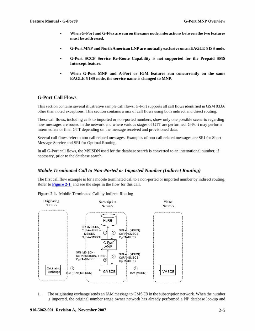
The first call flow example is for a mobile terminated call to a non-ported or imported number by indirect routing.Refer to Figure 2-1 and see the steps in the flow for this call.
Figure 2-1. Mobile Terminated Call by Indirect Routing
1. The originating exchange sends an IAM message to GMSCB in the subscription network. When the numberis imported, the original number range owner network has already performed a NP database lookup and
Feature Manual - G-Port® G-Port MNP Overview
910-5062-001 Revision A, November 2007 2-5

determined the new subscription network (Routing Number). As shown in the figure, this could be sent inthe IAM along with the MSISDN.
2. GMSCB sends a SRI request to the MNP-SRF. This request may or may not contain the new TT = SRI.Global title information triggers G-Port processing. The MNP-SRF determines the message is an SRI anduses the MSISDN from the MAP message to search the G-Port Database (GPDB). A match is found withno Routing Number and a HLR GT address for HLRB, or no match is found and falls through to GTT,producing a routing to HLRB. Alternatively, GTT could route to another node, possibly in a differentnetwork, but that is not illustrated here.
3. The message is routed to HLRB.
4. HLRB responds to GMSCB with a SRI ack. This message can be GT routed through the STP or MTP routed.
5. GMSCB sends an IAM with the roaming number to the visited network.
Mobile Originated/Terminated Call to an Exported Number (Direct Routing)
This call flow example is for a call that is mobile originated or terminated to an exported number by direct routing.Refer to Figure 2-2 and see the steps in the flow for this call.
Figure 2-2. Call to an Exported Number by Direct Routing
This call flow assumes the originating network is not the subscription network. If indirect routing were used inthis example, the originating network would first route the call to the number range owner network, according topre-portability rules, where the MNP-SRF and NPDB are accessed to locate the Routing Number.
G-Port MNP Overview Feature Manual - G-Port®
2-6 910-5062-001 Revision A, November 2007
1. When the call is originated, VMSCA sends an IAM message to GMSCA.
2. GMSCA sends a SRI request to the MNP-SRF. This may or may not contain the new TT = SRI. Global titleinformation triggers G-Port processing. The MNP-SRF determines the message is an SRI and uses theMSISDN from the MAP message to search the GPDB. A match is found with the Routing Number fieldpopulated.
3. The MNP-SRF responds to GMSCA with a SRI ack containing the Routing Number prefixed to theMSISDN number as the Roaming Number.
4. GMSCA sends an IAM with the roaming number to the subscription network. The Routing Number is usedby GMSCA and possibly by transit exchanges to route the call to the subscription network.
MO/MT Call to a Number Not Known to be Ported (Direct Routing)
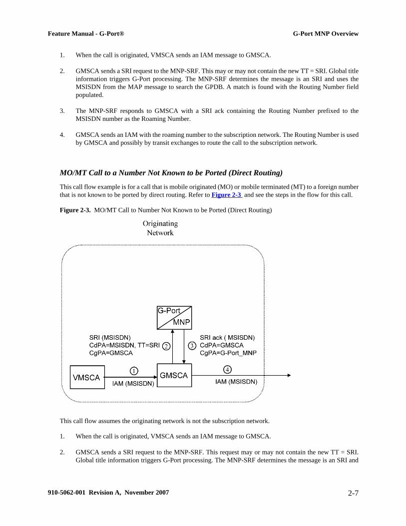
This call flow example is for a call that is mobile originated (MO) or mobile terminated (MT) to a foreign numberthat is not known to be ported by direct routing. Refer to Figure 2-3 and see the steps in the flow for this call.
Figure 2-3. MO/MT Call to Number Not Known to be Ported (Direct Routing)
This call flow assumes the originating network is not the subscription network.
1. When the call is originated, VMSCA sends an IAM message to GMSCA.
2. GMSCA sends a SRI request to the MNP-SRF. This request may or may not contain the new TT = SRI.Global title information triggers G-Port processing. The MNP-SRF determines the message is an SRI and
Feature Manual - G-Port® G-Port MNP Overview
910-5062-001 Revision A, November 2007 2-7

uses the MSISDN from the MAP message to search the GPDB. A match is found, but the Routing Numberand HLR Address fields are not populated.
3. The MNP-SRF responds to GMSCA with a SRI ack containing the MSISDN number.
4. GMSCA sends an IAM with the roaming number to the subscription network.
Non-Call Related Message for Non-Ported Number (Indirect Routing)
This call flow example is for a non-call related message for a non-ported number by indirect routing. Refer toFigure 2-4 and see the steps in the flow for this call.
Figure 2-4. Non-Call Related Message for Non-Ported Number
1. The Interrogating Network Entity (INE) sends the non-call related message to MNP-SRFB in the numberrange owner network. The SCCP CdPA contains the MSISDN number of the subscriber and the TT. TheTT may be either 0 as shown in the figure, or another value depending upon the service, such as TT=17 forCCBS service.
2. Global title information triggers G-Port processing. MNP-SRFB determines the message is non-call related(i.e. not an SRI that doesn't require Optimal Routing) and uses the MSISDN from the SCCP CdPA to searchthe GPDB. No match is found, so MNP-SRFB uses GTT to locate the GT address associated with theMSISDN to route the message to HLRB.
G-Port MNP Overview Feature Manual - G-Port®
2-8 910-5062-001 Revision A, November 2007

Non-Call Related Message for Ported Number (Indirect Routing)
This call flow example is for a non-call related message for a ported number by indirect routing. Refer to Figure2-5 and see the steps in the flow for this call.
Figure 2-5. Non-Call Related Message for Ported Number
1. The Interrogating Network Entity (INE) sends a non-call related message to MNP-SRFA in the numberrange owner network. The SCCPCdPA contains the MSISDN number of the subscriber and the TT. TheTT may be either 0 as shown in the figure, or another value depending upon the service, such as TT=17 forCCBS service.
2. Global title information triggers G-Port processing. MNP-SRFA determines the message is one requiringmessage relay (that is, not an SRI that doesn't require Optimal Routing) and uses the MSISDN from theSCCPCdPA to search the GPDB. A match is found, and MNP-SRFA uses the Message Relay GT addressassociated with the match to route the message to the subscription network.
3. MNP-SRFB receives the message and determines the message is one requiring message relay (that is, notan SRI that doesn't require Optimal Routing). It checks to see if the SCCPCdPA begins with a PrefixedRN. If so, it removes the prefix. Either way, it uses the MSISDN from the SCCPCdPA to search theGPDB. A match is found, and MNP-SRFB uses the HLRGT address associated with the match to route themessage to HLRB.
Non-Call Related Message for Ported or Non-Ported Number (Direct Routing)
This call flow example is for a non-call related message for either a ported or non-ported number by direct routing.Refer to Figure 2-6 and see the steps in the flow for this call.
Feature Manual - G-Port® G-Port MNP Overview
910-5062-001 Revision A, November 2007 2-9

Figure 2-6. Non-Call Related Message for Any Number
This call flow assumes the originating network is not the subscription network.
1. The Interrogating Network Entity (INE) sends the non-call related message to MNP-SRFA in theinterrogating network. The SCCP CdPA contains the MSISDN number of the subscriber and the TT. TheTT may be either 0 as shown in the figure, or another value depending upon the service, such as TT=17 forCCBS service.
2. Global title information triggers G-Port processing. MNP-SRFA determines the message is one requiringmessage relay (that is, not an SRI that doesn't require Optimal Routing) and uses the MSISDN from theSCCP CdPA to search the GPDB.
• If a match is found (ported case), MNP-SRFA uses the Message Relay GT address associated withthe match to route the message to the subscription network.
• If a match is not found (non-ported case), MNP-SRFA uses GTT to route the message to MNP-SRFB.
3. MNP-SRFB receives the message and determines the message requires message relay (that is, not an SRIthat doesn't require Optimal Routing). It checks to see if the SCCP CdPA begins with a Prefixed RN. If so,it removes the prefix. Either way, it uses the MSISDN from the SCCP CdPA to search the GPDB.
• If a match is found (imported case), MNP-SRFB uses the HLR GT address associated with the matchto route the message to HLRB.
• If a match is not found, MNP-SRFB uses GTT to route the message to HLRB.
PPSMS Call Flows
The MAP_FORWARD_SHORT_MESSAGE (FSM), in the following Call Flow examples is used to carry a textmessage (short message) being transmitted from the mobile handset of one subscriber to the mobile handset ofanother subscriber. In practice, the short message is delivered first to the Short Message Service Center (SMSC)of the sending subscriber. The SMSC is then responsible for sending the short message to the intended recipient.
G-Port MNP Overview Feature Manual - G-Port®
2-10 910-5062-001 Revision A, November 2007
Successful Delivery of Mobile Originated FSM from Contract/Postpaid Subscriber
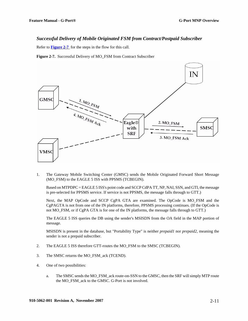
Refer to Figure 2-7 for the steps in the flow for this call.
Figure 2-7. Successful Delivery of MO_FSM from Contract Subscriber
1. The Gateway Mobile Switching Center (GMSC) sends the Mobile Originated Forward Short Message(MO_FSM) to the EAGLE 5 ISS with PPSMS (TCBEGIN).
Based on MTPDPC = EAGLE 5 ISS's point code and SCCP CdPA TT, NP, NAI, SSN, and GTI, the messageis pre-selected for PPSMS service. If service is not PPSMS, the message falls through to GTT.)
Next, the MAP OpCode and SCCP CgPA GTA are examined. The OpCode is MO_FSM and theCgPAGTA is not from one of the IN platforms, therefore, PPSMS processing continues. (If the OpCode isnot MO_FSM, or if CgPA GTA is for one of the IN platforms, the message falls through to GTT.)
The EAGLE 5 ISS queries the DB using the sender's MSISDN from the OA field in the MAP portion ofmessage.
MSISDN is present in the database, but "Portability Type" is neither prepaid1 nor prepaid2, meaning thesender is not a prepaid subscriber.
2. The EAGLE 5 ISS therefore GTT-routes the MO_FSM to the SMSC (TCBEGIN).
3. The SMSC returns the MO_FSM_ack (TCEND).
4. One of two possibilities:
a. The SMSC sends the MO_FSM_ack route-on-SSN to the GMSC, then the SRF will simply MTP routethe MO_FSM_ack to the GMSC. G-Port is not involved.
Feature Manual - G-Port® G-Port MNP Overview
910-5062-001 Revision A, November 2007 2-11

b. The SMSC sends the MO_FSM_ack route-on-GT, and the service selectors indicate G-Port/PPSMS.CdPA SSN = GMSC, which is same as SMSC, so PPSMS is selected. As PPSMS decodes message,it discovers it is a TCEND. Therefore, the message falls through to normal GTT and is routed to theGMSC.
Successful Delivery of Mobile Originated FSM from Prepaid Subscriber
Refer to Figure 2-8 for the steps in the flow for this call.
Figure 2-8. Successful Delivery of Mobile Originated FSM from Prepaid Subscriber
1. The Gateway Mobile Switching Center (GMSC) sends the Mobile Originated Forward Short Message(MO_FSM) to the EAGLE 5 ISS with PPSMS (TCBEGIN).
Based on MTPDPC = EAGLE 5 ISS's point code and SCCP CdPA TT, NP, NAI, SSN, and GTI, the messageis pre-selected for PPSMS service. If service is not PPSMS, the message falls through to GTT).
Next, the MAP OpCode and SCCP CgPA GTA are examined. The OpCode is MO_FSM and theCgPAGTA is not from one of the IN platforms, therefore, PPSMS processing continues. (If OpCode is notMO_FSM, or if CgPA GTA is for one of the IN platforms, the message falls through to GTT).
The EAGLE 5 ISS queries the DB using sender's MSISDN from SM RP OA field in MAP portion of message.
MSISDN is present in the database, and the "Portability Type" is prepaid1, meaning the sender is a prepaidsubscriber.
2. The EAGLE 5 ISS forwards the MO_FSM to the IN Platform (TCBEGIN) associated with "prepaid1", afterchecking mated application or mated relay node table
NOTE: The Portability Types prepaid1 and prepaid2 are used to select which of the twoIN platforms the message should be sent. prepaid1 indicates one and prepaid2 the other.
G-Port MNP Overview Feature Manual - G-Port®
2-12 910-5062-001 Revision A, November 2007
3. The IN Platform checks the account, finds there is enough credit to send the message, opens a new TCAPdialogue, and returns the MO_FSM to the SRF (TCBEGIN-2).
4. The message arrives at EAGLE 5 ISS and is again selected for PPSMS service based on CdPATT, NP,NAI, GTI, and CdPA SSN = SMSC. The OpCode is MO_FSM but the SCCP CgPA GTA is IN platform,therefore, PPSMS service is not indicated and the message falls through to GTT and is routed to theSMSC.
5. The SMSC returns the MO_FSM_ack to the IN platform (TCEND-2). There are two possibilities:
a. The SMSC sends the MO_FSM_ack route-on-SSN to the IN platform, then the SRF will simplyMTP route the MO_FSM_ack to the IN platform. G-Port is not involved.
b. The SMSC sends the MO_FSM_ack route-on-GT, and the service selectors indicate G-Port/PPSMS.CdPA SSN = GMSC, which is same as SMSC, so PPSMS is selected. As PPSMS decodes the message,it discovers it is a TCEND. Therefore, the message falls through to normal GTT and is routed to theGMSC.
6. The IN Platform transfers the MO_FSM_ack to the first transaction and returns the MO_FSM_ack to theSRF (TCEND).
7. One of two possibilities:
a. The IN platform sends the MO_FSM_ack route-on-SSN to the GMSC, then the SRF will simplyMTP route the MO_FSM_ack to the GMSC. G-Port is not involved.
b. The IN platform sends the MO_FSM_ack route-on-GT, and the service selectors indicate G-Port/PPSMS. CdPA SSN = GMSC, which is same as SMSC, so PPSMS is selected. PPSMS decodesmessage, discovers it is a TCEND, and the message falls through to normal GTT and is routed to theGMSC.
Unsuccessful Delivery of Mobile Originated FSM from Prepaid Subscriber - Credit CheckFailure
Refer to Figure 2-9 for the steps in the flow for this call.
Feature Manual - G-Port® G-Port MNP Overview
910-5062-001 Revision A, November 2007 2-13

Figure 2-9. Unsuccessful Delivery of Mobile Originated FSM from Prepaid Subscriber at SCP
1. The Gateway Mobile Switching Center (GMSC) sends the Mobile Originated Forward Short Message(MO_FSM) to the EAGLE 5 ISS with PPSMS (TCBEGIN).
Based on MTPDPC = EAGLE 5 ISS's point code and SCCP CdPA TT, NP, NAI, and GTI, the message ispre-selected for PPSMS service. If service is not PPSMS, the message falls through to GTT).
Next, the MAP OpCode and SCCP CgPA GTA are examined. The OpCode is MO_FSM and theCgPAGTA is not from one of the IN platforms, therefore, PPSMS processing continues. (If the OpCode isnot MO_FSM, or if CgPA GTA is for one of the IN platforms, the message falls through to GTT).
The EAGLE 5 ISS queries the DB using sender's MSISDN from the SM RP OA field in the MAP portionof message.
MSISDN is present in the database, and the "Portability Type" is prepaid1, meaning the sender is a prepaidsubscriber.
2. The EAGLE 5 ISS forwards the MO_FSM to the IN Platform (TCBEGIN) associated with prepaid1.NOTE: The Portability Types prepaid1 and prepaid2 are used to select which of the twoIN platforms the message should be sent to. prepaid1 indicates one and prepaid2 the other.
3. The IN Platform checks the account, finds there is not enough credit to send the message, and rejects themessage by returning a MO_FSM_Neg_Response to the SRF (TCEND).
4. One of two possibilities:
a. The IN platform sends the MO_FSM_Neg_Response route-on-SSN, then the SRF will simply MTProute the MO_FSM_Neg_Response to the GMSC. G-Port is not involved.
b. The IN platform sends the MO_FSM_Neg_Response route-on-GT, and the service selectors indicateG-Port/PPSMS. CdPA SSN = GMSC, which is same as SMSC, so PPSMS service is selected.
G-Port MNP Overview Feature Manual - G-Port®
2-14 910-5062-001 Revision A, November 2007
PPSMS decodes message, discovers it is a TCEND, and the message falls through to normal GTT andis routed to the GMSC.
Portability Check for Mobile Originated SMS
Refer to the following steps in the flow for this call.
The EAGLE 5 ISS will perform following with respect to MNPSMS Feature functionality.
1. The EAGLE 5 ISS receives an UDT message and checks if the service selector matches G-Port, if so continueon to Step 2 , If the service selector is not G-Port, the message falls through to GTT.
2. The EAGLE 5 ISS performs CdPA SSN discrimination. CdPA SSN = SMSC, PPSMS service is selected.(If CdPA SSN is HLR, G-Port MNP service is selected. If SSN is neither SMSC nor HLR, the message fallsthrough to GTT.)
3. Next the MAP OpCode is examined. If the OpCode is MO_FSM, PPSMS processing continues. (If theOpCode is not MO_FSM, the message falls through to GTT.)
4. If The PPSMS feature is ON and the message is from one of the IN Platforms (PPSMS Servers), the messageexists from MNP SMS feature functionality and falls through to PPSMS processing. If not, MNPSMSprocessing continues with Step 5.
5. If the MNP SMS feature is ON, the MSISDN number is used to search the G-Port Mobile Number Portabilitysubscriber database. If the MNP SMS feature is not ON, the message falls through to GTT.
6. If the MSISDN Number is found in the PDB/DN table, then the portability type of the subscriber is checkedfor Ported-out/ Not Known/ FNPTFN and processing continues. If the MSISDN Number is not found in thePDB/DN table, the message falls through to GTT. If the portability type is Prepaid-1/Prepaid-2 the messagefalls through to GTT.
7. The SCCP CdPA Addressis used to search the list of "home network" SMSC addresses. If a match is found,the ported-out subscriber is fraudulently attempting to send SMS using the old network's SMSC. The messageis discarded, UIM #1129 is issued, and an error message is generated and returned to the originating MSC.If the message is not on the list, the message falls through to GTT.
8. The message will be discarded, Print an UIM #1129 and an error message is generated and returned to theoriginating MSC. The message exists from MNP SMS feature functionality.
9. It's a fall through case. Exit from MNP SMS feature functionality and continue with Normal GTT processing.
10. If the message is from one of the IN Platforms (PPSMS Servers), The message exists from MNP SMS featurefunctionality and falls through to PPSMS processing. If the message is not from one of the PPSMS Serversprocessing continues with step 13
11. The originating subscriber's Mobile Subscriber Integrated Services Digital Network (MSISDN) number (i.e.phone number) will be used to search the G-Port Mobile Number Portability subscriber database. If theMSISDN Number is found in the PDB / DN table, then continue on to Step 12. Otherwise, exit fromMNP SMS feature functionality and continue with Normal GTT processing..
12. Check the portability type of the subscriber, If it matches "Prepaid1/Prepaid2" go on to Step 16 else continuewith Step 13.
Feature Manual - G-Port® G-Port MNP Overview
910-5062-001 Revision A, November 2007 2-15
13. If the subscriber portability type is "Ported out / FNPTFN/ Not Known" and MNP SMS feature is alsoON, then go to Step 7. Otherwise, exit from MNP SMS feature functionality and continue with NormalGTT processing.
14. Exit from MNP SMS feature functionality and Continue with existing processing for other services orGTT.
15. Exit from MNP SMS feature functionality and Continue with existing processing for GPORT.
16. Exit from MNP SMS feature functionality and Continue with existing processing for PPSMS.
17. Exit from MNP SMS feature functionality.
ISUP NP with EPAP Call Flows
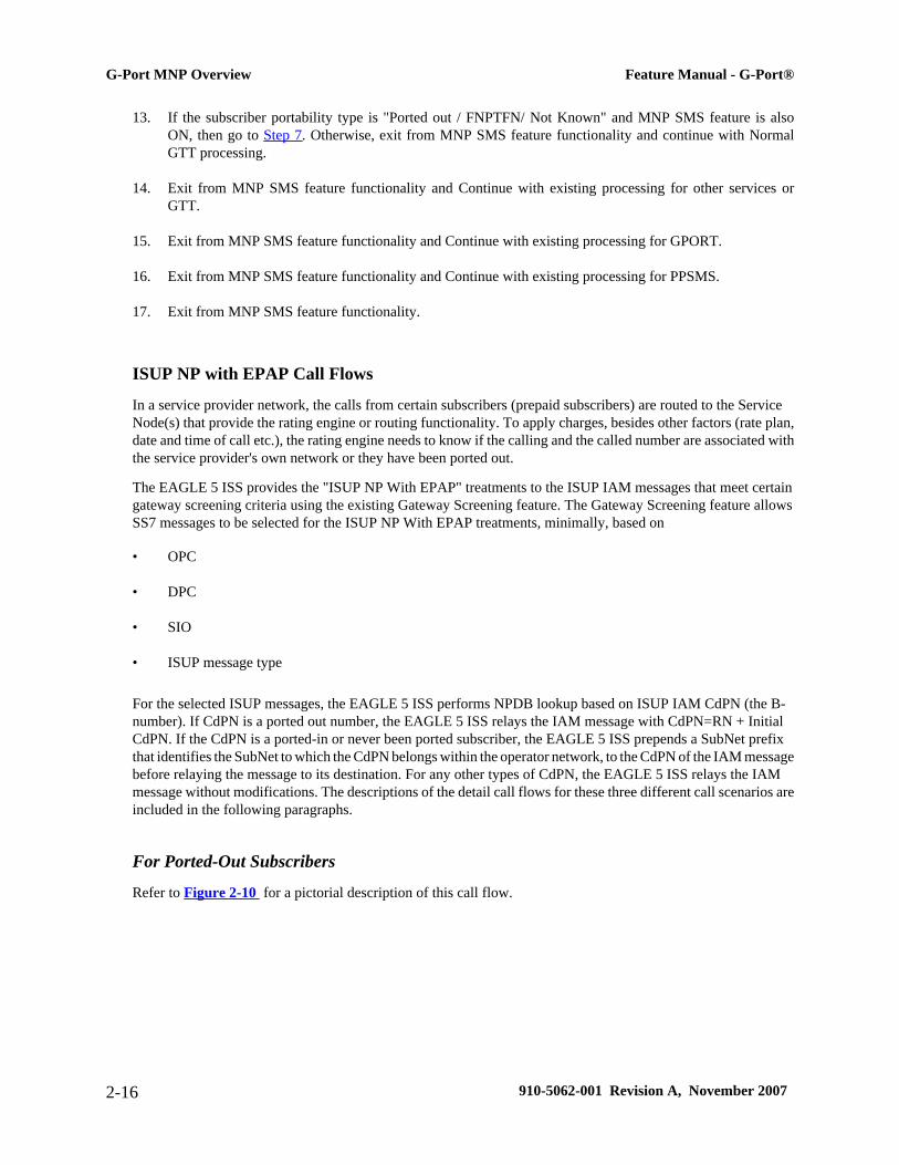
In a service provider network, the calls from certain subscribers (prepaid subscribers) are routed to the ServiceNode(s) that provide the rating engine or routing functionality. To apply charges, besides other factors (rate plan,date and time of call etc.), the rating engine needs to know if the calling and the called number are associated withthe service provider's own network or they have been ported out.
The EAGLE 5 ISS provides the "ISUP NP With EPAP" treatments to the ISUP IAM messages that meet certaingateway screening criteria using the existing Gateway Screening feature. The Gateway Screening feature allowsSS7 messages to be selected for the ISUP NP With EPAP treatments, minimally, based on
• OPC
• DPC
• SIO
• ISUP message type
For the selected ISUP messages, the EAGLE 5 ISS performs NPDB lookup based on ISUP IAM CdPN (the B-number). If CdPN is a ported out number, the EAGLE 5 ISS relays the IAM message with CdPN=RN + InitialCdPN. If the CdPN is a ported-in or never been ported subscriber, the EAGLE 5 ISS prepends a SubNet prefixthat identifies the SubNet to which the CdPN belongs within the operator network, to the CdPN of the IAM messagebefore relaying the message to its destination. For any other types of CdPN, the EAGLE 5 ISS relays the IAMmessage without modifications. The descriptions of the detail call flows for these three different call scenarios areincluded in the following paragraphs.
For Ported-Out Subscribers
Refer to Figure 2-10 for a pictorial description of this call flow.
G-Port MNP Overview Feature Manual - G-Port®
2-16 910-5062-001 Revision A, November 2007
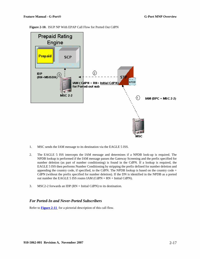
Figure 2-10. ISUP NP With EPAP Call Flow for Ported Out CdPN
1. MSC sends the IAM message to its destination via the EAGLE 5 ISS.
2. The EAGLE 5 ISS intercepts the IAM message and determines if a NPDB look-up is required. TheNPDB lookup is performed if the IAM message passes the Gateway Screening and the prefix specified fornumber deletion (as part of number conditioning) is found in the CdPN. If a lookup is required, theEAGLE 5 ISS then performs Number Conditioning by stripping the prefix defined for number deletion andappending the country code, if specified, to the CdPN. The NPDB lookup is based on the country code +CdPN (without the prefix specified for number deletion). If the DN is identified in the NPDB as a portedout number the EAGLE 5 ISS routes IAM (CdPN = RN + Initial CdPN).
3. MSC2-2 forwards an IDP (RN + Initial CdPN) to its destination.
For Ported-In and Never-Ported Subscribers
Refer to Figure 2-11 for a pictorial description of this call flow.
Feature Manual - G-Port® G-Port MNP Overview
910-5062-001 Revision A, November 2007 2-17

Figure 2-11. ISUP NP With EPAP Call Flow for Ported-In/Never Ported CdPN
1. MSC sends the IAM message to its destination via the EAGLE 5 ISS.
2. The EAGLE 5 ISS intercepts the IAM message and determines if a NPDB look-up is required. TheNPDB lookup is performed if the IAM message passes the Gateway Screening and the prefix specified fornumber deletion (as part of number conditioning) is found in the CdPN. If a lookup is required, theEAGLE 5 ISS then performs Number Conditioning by stripping the prefix defined for number deletion andappending the country code, if specified, to the CdPN. The NPDB lookup is based on the country code +CdPN (without the prefix specified for number deletion). The NPDB lookup identifies the CdPN as a ported-in number or never been ported DN (the DN is within the operator's DN ranges and the DN has never beenported). The EAGLE 5 ISS performs SubNet ID Lookup to locate the SubNet Number. The SubNet IDlookup is based on the entity address pointed to by the SP that is associated with the DN (where DN=CdPN)or associated with a range of DNs (this assumes that all range DNs for each HLR are provisioned with anSP in the NPDB). Once the SubNet Number is identified, the EAGLE 5 ISS looks up the SubNet Prefix tableto identify the prefix for the SubNet. The EAGLE 5 ISS prepends the SubNet prefix, associated with theSubNet No, to CdPN. The EAGLE 5 ISS routes IAM (CdPN = SubNet prefix + Initial CdPN).
3. MSC2-2 forwards an IDP (SubNet ID + Initial CdPN) to its destination.
G-Port MNP Overview Feature Manual - G-Port®
2-18 910-5062-001 Revision A, November 2007
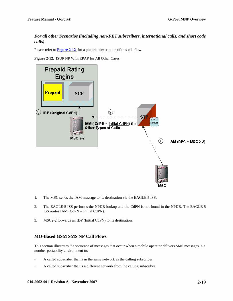
For all other Scenarios (including non-FET subscribers, international calls, and short codecalls)
Please refer to Figure 2-12 for a pictorial description of this call flow.
Figure 2-12. ISUP NP With EPAP for All Other Cases
1. The MSC sends the IAM message to its destination via the EAGLE 5 ISS.
2. The EAGLE 5 ISS performs the NPDB lookup and the CdPN is not found in the NPDB. The EAGLE 5ISS routes IAM (CdPN = Initial CdPN).
3. MSC2-2 forwards an IDP (Initial CdPN) to its destination.
MO-Based GSM SMS NP Call Flows
This section illustrates the sequence of messages that occur when a mobile operator delivers SMS messages in anumber portability environment to:
• A called subscriber that is in the same network as the calling subscriber
• A called subscriber that is a different network from the calling subscriber
Feature Manual - G-Port® G-Port MNP Overview
910-5062-001 Revision A, November 2007 2-19

NOTE: The MO-Based GSM SMS NP feature must be enabled and turned on before messages are processedas shown in this section.
Figure 2-13. MO-Based GSM SMS NP Call Flow for In-Network Subscriber
Call considerations:
• The TCAP calling party is a wireless GSM subscriber
• The TCAP called party is a non-ported or ported-in wireless subscriber that belongs to the same carrier asthe TCAP calling party
• The call type is SMS
• The SMSC (Short Message Service Center) has to remove the prefix that indicates that the DN (dialednumber) is ported in
• If the called subscriber is ported-in, it must be provisioned individually
• If the called subscriber is TDMA, the EAGLE IS41-to-GSM NP feature ensures that the message getsdelivered in the TDMA network.
Message Flow:
1. MO_SMS(B) - EAGLE 5 ISS intercepts SMS messages after they have undergone Prepaid SMS (PPSMS)and Portability Check for Mobile Originated SMS (MNPSMS) processing and decodes the TCAP/MAPmessage destination address.
2. MO_SMS(SP+B) - If successful, modify B-party Number and relay to SMSC.
G-Port MNP Overview Feature Manual - G-Port®
2-20 910-5062-001 Revision A, November 2007

3. SRI_SM(B) - Send message to HLR to find B-party.
4. SRI_SM - Send message to HLR to locate B-party.
5. SRI_SM Ack - HLR sends message to EAGLE 5 ISS.
6. SRI_SM Ack - EAGLE 5 ISS routes message to SMSC.
7. MT_SMS - Deliver message to in-network subscriber.
Figure 2-14. MO-Based GSM SMS NP Call Flow for Other-Network Subscriber
Call considerations:
• The TCAP calling party is a wireless IS41 subscriber
• The TCAP called party is a non-ported or ported-in wireless subscriber that belongs to a different carrierfrom the TCAP calling party
• The call type is SMS
• The SMSC (Short Message Service Center) has to remove the prefix that indicates that the DN (dialednumber) is ported in If the called subscriber is ported-out, it must be provisioned individually
• If the called subscriber is TDMA, the EAGLE IS41-to-GSM NP feature ensures that the message getsdelivered in the TDMA network.
Message Flow:
Feature Manual - G-Port® G-Port MNP Overview
910-5062-001 Revision A, November 2007 2-21

1. MO_SMS(B) - EAGLE 5 ISS intercepts SMS messages after they have undergone Prepaid SMS (PPSMS)and Portability Check for Mobile Originated SMS (MNPSMS) processing and decodes the TCAP/MAPmessage destination address.
2. MO_SMS(SP+B) - If successful, modify B-party Number and relay to SMSC.
3. Deliver_SM - Forward message or submit message other network.
Subscriber Data Provisioning
Figure 2-15 shows the current high-level view of the subscriber data provisioning architecture that will be usedfor G-Port. Only those parts of the EAGLE 5 ISS platform that are relevant to subscriber data provisioning areshown. This section defines requirements for the PDBI (Provisioning Database Interface) between the G-Port andthe operator's provisioning system (OPS). The PDBI is used only for real-time provisioning of subscriber andnetwork entity data. Refer to the PDBI Manual for more details about the G-Port PDBI.
Provisioning clients connect to the EPAPs via the Provisioning Database Interface (PDBI). This interface containscommands that allow all of the provisioning and retrieving of G-Port data. The PDBI is used only for real-timeprovisioning of subscriber and network entity data. Refer to the Provisioning Database Interface Manual for moredetails about the G-Port PDBI.
Figure 2-15. Subscriber Data Provisioning Architecture (High Level)
A pair of active/standby EPAP (EAGLE Provisioning Application Processors) servers provides the interfacebetween the Realtime Database (RTDB) of the EAGLE 5 ISSDSMs (Database Service Modules) and the OPS.
G-Port MNP Overview Feature Manual - G-Port®
2-22 910-5062-001 Revision A, November 2007
EPAP A is equipped with both the PDB (Provisioning Database) and the RTDB database, and EPAP B has justthe RTDB. An EPAP with just the RTDB must be updated by the EPAP that has the PDB. The EPAP uses theMulti-Purpose Server (MPS) hardware.
For more information about the EPAP, refer to the EPAP Administration Manual. For more information about theMPS hardware, refer to the Tekelec 1000 Application Server Hardware Manual.
Database Overview
This section describes, at a high level, the distributed administrative architecture for the EAGLE 5 ISS, whichincludes the G-Port administrative solution.
In general, database updates are sent via an EAGLE 5 ISS terminal across an RS232 serial port to the activeOAM (Operation Administration and Maintenance). The active OAM commits the update to TDM fixed disk andthen sends the update control information to the standby OAM and to the rest of the network cards. When alldatabases are updated, the active OAM responds with a Command Completed indication to the user terminal.STP database updates are generally considered to be EAGLE 5 ISS link, linkset, route, destination, matedapplication, gateway screening, and global title types of information.
Typically, large databases requiring much faster update and retrieval rates (compared to the rates provided by theOAM) are not administered via EAGLE 5 ISS terminals. These subscriber databases, such as G-Port, are populatedusing redundant Ethernet connections to DSM cards from an EPAP MPS platform.
An EPAP consists of a combined Provisioning (MySQL) and RTDB database. The Provisioning Database respondsto requests for updates by the active and standby RTDB databases on both mated EAGLE 5 ISSs. The activeEPAP RTDB database process is responsible for initiating multicast updates of changed database records to theDSM cards after the data has been committed to the EPAP disks. Furthermore, the Provisioning database mayaccept and commit to more database updates while the RTDB databases are completing their previous updates.
Feature Manual - G-Port® G-Port MNP Overview
910-5062-001 Revision A, November 2007 2-23

Figure 2-16. MPS/EPAP Platforms for Provisioning G-Port
It is this overlapping of database updates, coupled with an RTDB transactional database engine and fast downloadtime, that allows larger amounts of data at a time from the PDB. Committing larger amounts of data at a time tobe committed in the RTDB (versus a single update at a time) results in achieving faster overall transaction rates.The boundaries of the transaction rates become more closely related to cache size and disk cache flush time thanthe disk access time of a single update. Thus, successful completion of EPAP database updates only guaranteesthat the PDB has been updated, but it does not mean the RTDB has already completed the update and sent it tothe DSM card.
The EPAP architecture contains a local provisioning terminal and a modem for remote access, as well as otherfunctions. A backup device can be used to backup or restore the Provisioning database. The local provisioningterminal is used to manually repair the standby EPAP RTDB database or to turn the G-Port database audit on oroff. For additional information, refer to the MPS Hardware Manual and the EPAP Administration Manual.
G-Port MNP Overview Feature Manual - G-Port®
2-24 910-5062-001 Revision A, November 2007

EPAP (EAGLE Provisioning Application Processor)
As shown in Figure 2-16 , a single G-Port system contains two EPAP (EAGLE Provisioning ApplicationProcessors) servers. At any given time, only one actively communicates with the DSM (Database Service Module)boards. The other EPAP server is in standby mode. In addition, two G-Port systems can be deployed in a matedpair configuration.
The primary purpose of the EPAP systems is to maintain the RTDB and PDB and to download copies of theRTDB to the DSM cards on the EAGLE 5 ISS.
The PDB on the active EPAP receives G-Port data from the customer network through the PDBI, the externalsource of G-Port provisioning information. The PDBA continually updates the active EPAP’s PDB. (The PDBuses MySQL database software.) Once an update is applied to the active PDB, it is sent to the RTDBs on the activeand standby EPAPs.
Both the active and standby EPAPs maintain copies of the RTDB. Periodically, the DSM card polls the activeEPAPRTDB for any new updates. The active EPAP downloads the updates to the DSM for its own resident copyof the RTDB database.
In a mated pair configuration, there are mated EPAP servers that provide two G-Port platforms, as shown in Figure2-16 . The PDB on the active EPAP automatically updates the PDB on the mate platform. The PDB on the mateplatform then updates its EPAPRTDBs, which in turn update the RTDBs on the DSM cards.
Provisioning of the EAGLE 5 ISS’s DSM cards is performed through two interfaces, using two different sets ofcommands. Provisioning is accomplished by the STP updates from EAGLE 5 ISS terminals and by the G-Portupdates from the customer’s external provisioning system. This system of dual provisioning is illustrated in Figure2-17 .
Feature Manual - G-Port® G-Port MNP Overview
910-5062-001 Revision A, November 2007 2-25
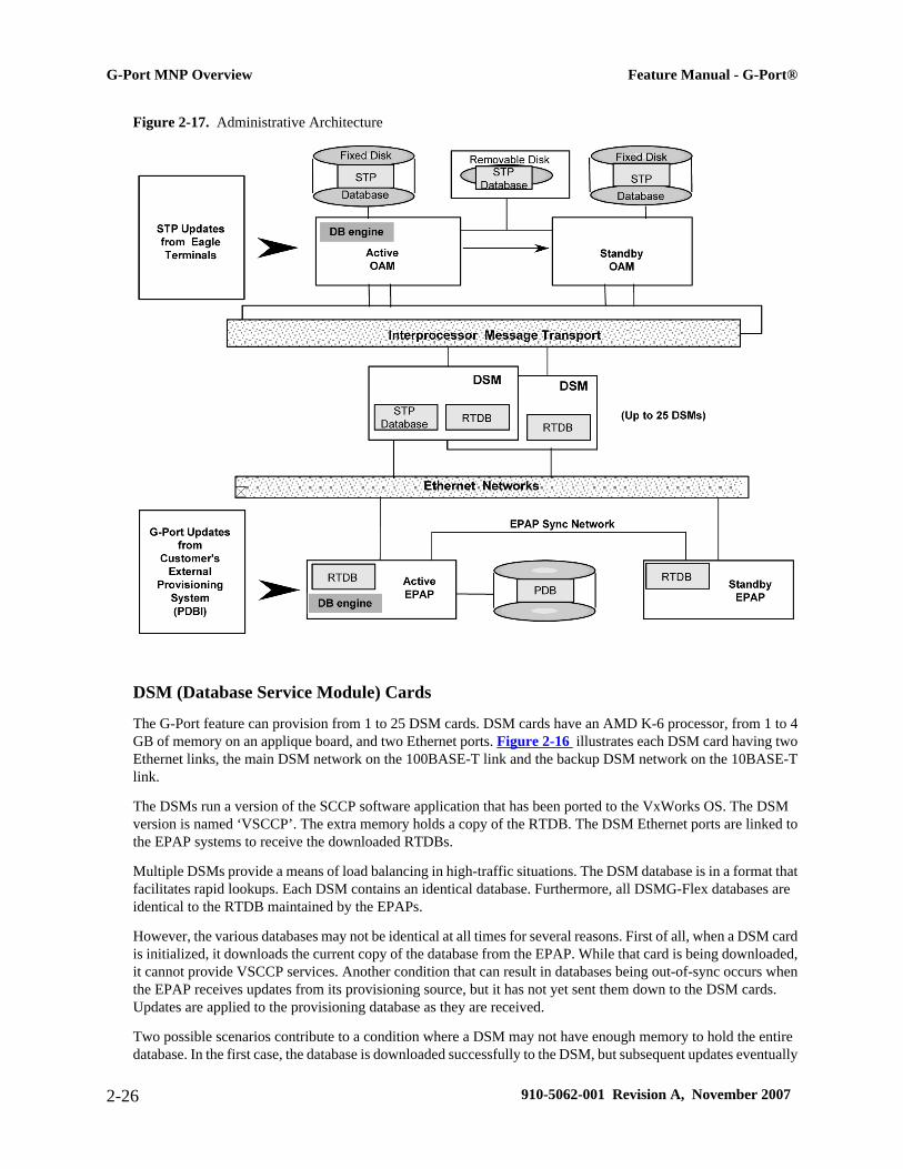
Figure 2-17. Administrative Architecture
DSM (Database Service Module) Cards
The G-Port feature can provision from 1 to 25 DSM cards. DSM cards have an AMD K-6 processor, from 1 to 4GB of memory on an applique board, and two Ethernet ports. Figure 2-16 illustrates each DSM card having twoEthernet links, the main DSM network on the 100BASE-T link and the backup DSM network on the 10BASE-Tlink.
The DSMs run a version of the SCCP software application that has been ported to the VxWorks OS. The DSMversion is named ‘VSCCP’. The extra memory holds a copy of the RTDB. The DSM Ethernet ports are linked tothe EPAP systems to receive the downloaded RTDBs.
Multiple DSMs provide a means of load balancing in high-traffic situations. The DSM database is in a format thatfacilitates rapid lookups. Each DSM contains an identical database. Furthermore, all DSMG-Flex databases areidentical to the RTDB maintained by the EPAPs.
However, the various databases may not be identical at all times for several reasons. First of all, when a DSM cardis initialized, it downloads the current copy of the database from the EPAP. While that card is being downloaded,it cannot provide VSCCP services. Another condition that can result in databases being out-of-sync occurs whenthe EPAP receives updates from its provisioning source, but it has not yet sent them down to the DSM cards.Updates are applied to the provisioning database as they are received.
Two possible scenarios contribute to a condition where a DSM may not have enough memory to hold the entiredatabase. In the first case, the database is downloaded successfully to the DSM, but subsequent updates eventually
G-Port MNP Overview Feature Manual - G-Port®
2-26 910-5062-001 Revision A, November 2007
increase the size of the database beyond the capacity of the DSM memory. In this situation, it is desirable tocontinue processing G-Port transactions, even though the database may not be as up-to-date as it could be.
The other case occurs when a DSM card is booted. If it is determined then that the card does not have enoughmemory for the entire database, the database is not loaded on that card. Each DSM is responsible for recognizingand reporting its out-of-memory conditions by means of alarms.
Overview of EPAP to DSM Communications
Before discussing DSM status reporting or EPAP status reporting, it is helpful to understand the communicationsbetween the DSMs and the EPAP in broad terms.
• UDP - sending DSM status messagesThe DSMs and EPAPs create a UDP (User Datagram Protocol) socket, which is used for status messages.One of the last things a DSM does when it is initialized is to send a status message to the EPAP, containingthe DSMID, database level, and memory size. The EPAP maintains tables containing the last known statusof each DSM. EPAP uses these to determine whether or not the DSM needs to download the database.
• IP - reporting EPAP maintenance dataThe DSMs create a TCP/IP socket when they are initialized, and listen for connection requests. Duringinitialization or after a loss of connectivity, the active EPAP chooses one of the DSMs and issues aConnect to establish the TCP/IP connection with that DSM (referred to as the primary DSM). The purposeof this link is to provide a path for reporting EPAP alarms and to forward maintenance blocks to theDSM.
• IP Multicast - downloading GSM databaseBecause of the large size of the database and the need to download it quickly on up to 25 DSM cards, G-Port uses a technique known as IP multicasting. This technique is based on Reliable Multicast TransportProtocol-II (RMTP-II), a product of Globalcast Communications. IP multicasting downloads the RTDB anddatabase updates to the DSMs.
The administration of IP multicasting is based on the concept of a “tree”, or stream of data, which is constantlybeing broadcast by the EPAP. DSMs that need to download the real time database or to receive databaseupdates “join the tree”. DSMs can also “leave the tree”, typically when the database fills their availablememory.
DSM Provisioning and Reload
One of the core functions of the EPAP is to provision the DSM cards with the G-Port database updates. In orderto provide redundancy for this feature, separate RMTP channels are created on each interface from each EPAP:
• EPAP A, Link A (on the main DSM network, 100BASE-T)
• EPAP A, Link B (on the backup DSM network, 10BASE-T)
• EPAP B, Link A (on the main DSM network, 100BASE-T)
• EPAP B, Link B (on the backup DSM network, 10BASE-T)
Provisioning and other data is broadcast on one of these channels to all of the DSM cards. Provisioning is doneby database level in order to leave DSM tables coherent between updates.
The DSM cards do the following:
Feature Manual - G-Port® G-Port MNP Overview
910-5062-001 Revision A, November 2007 2-27

• Detect the need for incremental updates and send a status message to the EPAP.
• Discriminate between the various streams by the database level contained in each message and accept updatesaccording to the DSMs current database level.
DSM Reloading Model
DSM cards may require a complete database reload in the event of reboot or loss of connectivity for a significantamount of time. The EPAP provides a mechanism to quickly load a number of DSM cards with the current database.The database on the EPAP is large and may be updated constantly. The database sent to the DSM card or cardswill likely be missing some of these updates making it corrupt as well as back level.
EPAP Continuous Reload
It is important to understand how the EPAP handles reloading of multiple DSMs from different starting points.Reload begins when the first DSM requires it. Records are read sequentially from the real-time database from anarbitrary starting point, wrapping back to the beginning. If another DSM requires reloading at this time, it uses theexisting record stream and notifies the DSM provisioning task of the first record it read. This continues until allDSMs are satisfied.
DSM Database Levels and Reloading
The current database level when the reload started is of special importance during reload. When a DSM detectsthat the last record has been received, it sends a status message back to the EPAP indicating the database level atthe start of reload. This action starts incremental loading. The DSM continues to reload until it is completely caughtup with the current level of the RTDB. As database records are sent to the DSMs during reload, normal provisioningcan change those records. All records changed between the start and end of reloading must be incrementally loadedbefore the database is coherent and usable by the DSM.
The following terminology is used here for the stages of database reload for a given DSM.
• Stage 1 loading: The database is being copied record for record from the golden RTDB to theDSMRTDB. The database is incoherent during stage 1 loading.
• Incremental update: The database is receiving all of the updates missed during stage 1 loading or someother reason (e.g., network outage, processor limitation, lost communication, etc.). The database is coherentbut back level during incremental update.
• Current: The database is receiving current updates from the DSM provisioning task.
• Coherent: The database is at a whole database level, that is, not currently updating records belonging to adatabase level.
DSM Reload Requirements
DSM cards may require a complete database reload if there is a reboot or loss of connectivity for a significantamount of time. The EPAP provides a mechanism to quickly load a number of DSM cards with the current database.The RTDB on the EPAP is large and can be updated constantly from the customer’s provisioning network.
The upload process is divided into two stages, one to sequentially send the initial database records and another tosend any updates missed since the beginning of the first stage. The DSM reload stream uses a separate RMTPchannel from the provisioning and incremental update streams. This allows DSM multicast hardware to filter outthe high volume of reload traffic from DSM cards that do not require it.
G-Port MNP Overview Feature Manual - G-Port®
2-28 910-5062-001 Revision A, November 2007

DSM cards do the following:
• Detect the need for stage 1 loading and send a status message to the EPAP.
• Identify the first record DSM was able to read in the above status message if a record stream is already inprogress.
• Handle the record stream regardless of the starting point (that is, records starting with the middle record ofthe middle table).
• Expect tables to be sent in a particular order and therefore detect any gap in the record stream.
• Send a status message if a gap is detected. Stage 1 loading is essentially reset to the last update received.
• Handle wrapping from the last record from the last table to the first record of the first table.o the last updatereceived.
• Know when they have received all the required records to proceed to stage 2 loading.`
• Send a status message when stage 1 loading is complete, indicating the database level at the beginning ofstage 1.
• Detect when the master RTDB crosses a memory boundary during stage 1 loading; the card automaticallyreboots and then auto-inhibits.
DSM Reload Requirements
DSM cards may require a complete database reload if there is a reboot or loss of connectivity for a significantamount of time. The EPAP provides a mechanism to quickly load a number of DSM cards with the current database.The RTDB on the EPAP is large and can be updated constantly from the customer’s provisioning network. As theRTDB is sent to the DSM cards, it can possibly miss some updates, making it inconsistent as well as back level.
The upload process is divided into two stages, one that sequentially sends the initial database records and anotherthat sends any updates missed since the beginning of the first stage. The DSM reload stream uses a separateRMTP channel from the provisioning and incremental update streams. This allows DSM multicast hardware tofilter out the high volume of reload traffic from DSM cards that do not require it.
DSM cards do the following:
• Detect the need for stage 1 loading and send a status message to the EPAP.
• Identify the first record DSM was able to read in the above status message if a record stream is already inprogress.
• Handle the record stream regardless of the starting point (that is, accomodate records starting with the middlerecord of the middle table).
• Expect tables to be sent in a particular order and therefore detect any gap in the record stream.
• Send a status message if a gap is detected. Stage1 loading is essentially reset to the last update received.
• Handle wrapping from the last record from the last table to the first record of the first table.
• Know when they have received all the required records to proceed to stage 2 loading.
• Send a status message when stage 1 loading is complete, indicating the database level at the beginning ofstage 1.
Feature Manual - G-Port® G-Port MNP Overview
910-5062-001 Revision A, November 2007 2-29

• Detect when the master RTDB crosses a memory boundary during stage 1 loading; the card automaticallyreboots and then auto-inhibits.
EPAP Status and Error Reporting via Maintenance Blocks
The EPAPs forward all status and error messages to the DSMs in maintenance blocks. Maintenance blocks areasynchronously sent whenever the EPAP has something to report. The maintenance blocks eventually updateEPAPDCBs located on the EAGLE 5 ISS. The DCBs provide the status information you receive when you issuea rept-stat-mps command.
Network Connections
Several customer- and Tekelec-installed private networks are required to support the G-Port feature. Thesenetworks are:
• Customer provisioning network
• EPAP sync network
• DSM networks
• Dial-up network
The following discussion is an overview of these private networks. It expands on the networks in the G-Portarchitecture diagram shown in Figure 2-16 . (For details about configuring these networks, refer to the EPAP UserInterface Manual.)
Customer Provisioning Network
The customer network carries the following traffic:
• Customer queries and responses to the PDB via the PDBI from the customer provisioning network
• Updates between PDBs if a mated EAGLE 5 ISS pair
• Updates between a PDB on one EAGLE 5 ISS and RTDBs on a mated EAGLE 5 ISS
• RTDB reload traffic if the active PDBA is not collocated on the same EPAP
• PDBA import/export (file transfer) traffic
• Traffic from a PDBA reloading from its mate
• EPAP and PDBA user interface traffic.
A typical customer network is shown in Figure 2-18 .
G-Port MNP Overview Feature Manual - G-Port®
2-30 910-5062-001 Revision A, November 2007

Figure 2-18. Customer Provisioning Network
Although a dedicated network is recommended, it is possible that unrelated customer traffic can use the networkas well. The determination to have a dedicated network or to allow other customer traffic, should be based onavailable external Ethernet bandwidth and network performance considerations.
EPAP Sync Network
The EPAP sync network carries RTDB and maintenance application traffic between active and standby EPAPservers on an EPAP system. It synchronizes the contents of the RTDBs of both EPAP A and B. The EPAP networkis a single Ethernet cable between EPAP A and EPAP B running at 100BASE-T, as shown in Figure 2-19 .
Feature Manual - G-Port® G-Port MNP Overview
910-5062-001 Revision A, November 2007 2-31
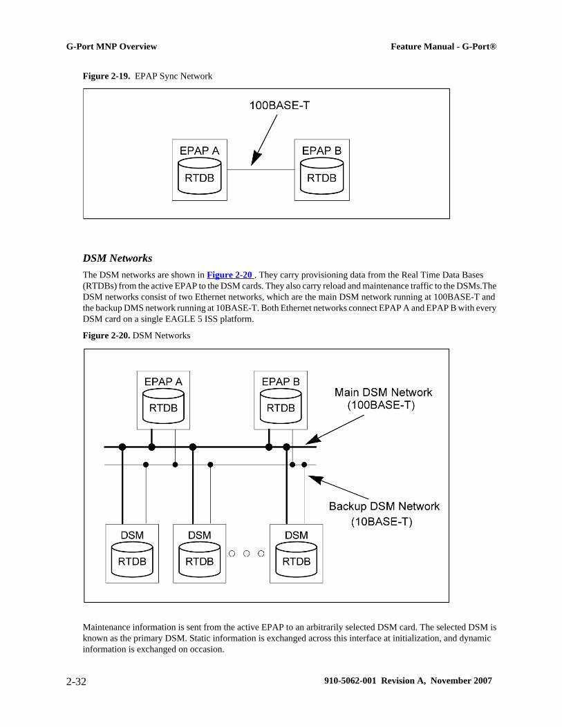
Figure 2-19. EPAP Sync Network
DSM NetworksThe DSM networks are shown in Figure 2-20 . They carry provisioning data from the Real Time Data Bases(RTDBs) from the active EPAP to the DSM cards. They also carry reload and maintenance traffic to the DSMs.TheDSM networks consist of two Ethernet networks, which are the main DSM network running at 100BASE-T andthe backup DMS network running at 10BASE-T. Both Ethernet networks connect EPAP A and EPAP B with everyDSM card on a single EAGLE 5 ISS platform.
Figure 2-20. DSM Networks
Maintenance information is sent from the active EPAP to an arbitrarily selected DSM card. The selected DSM isknown as the primary DSM. Static information is exchanged across this interface at initialization, and dynamicinformation is exchanged on occasion.
G-Port MNP Overview Feature Manual - G-Port®
2-32 910-5062-001 Revision A, November 2007
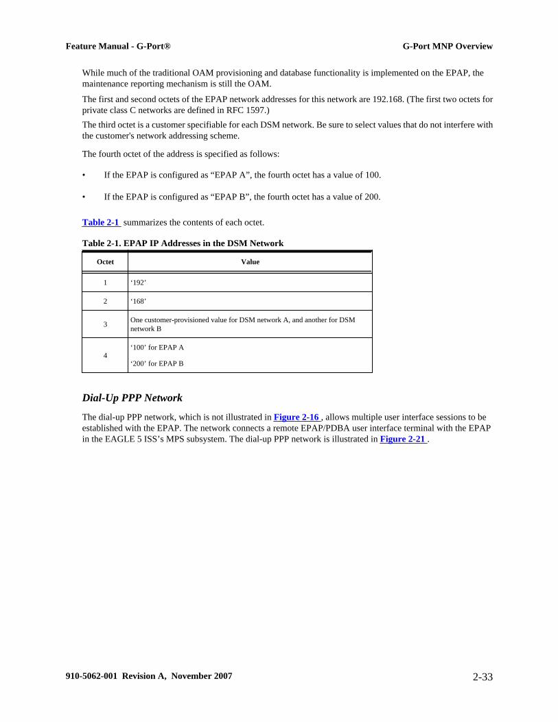
While much of the traditional OAM provisioning and database functionality is implemented on the EPAP, themaintenance reporting mechanism is still the OAM.
The first and second octets of the EPAP network addresses for this network are 192.168. (The first two octets forprivate class C networks are defined in RFC 1597.)The third octet is a customer specifiable for each DSM network. Be sure to select values that do not interfere withthe customer's network addressing scheme.
The fourth octet of the address is specified as follows:
• If the EPAP is configured as “EPAP A”, the fourth octet has a value of 100.
• If the EPAP is configured as “EPAP B”, the fourth octet has a value of 200.
Table 2-1 summarizes the contents of each octet.
Table 2-1. EPAP IP Addresses in the DSM Network
Octet Value
1 ‘192’
2 ‘168’
3 One customer-provisioned value for DSM network A, and another for DSMnetwork B
4‘100’ for EPAP A
‘200’ for EPAP B
Dial-Up PPP Network
The dial-up PPP network, which is not illustrated in Figure 2-16 , allows multiple user interface sessions to beestablished with the EPAP. The network connects a remote EPAP/PDBA user interface terminal with the EPAPin the EAGLE 5 ISS’s MPS subsystem. The dial-up PPP network is illustrated in Figure 2-21 .
Feature Manual - G-Port® G-Port MNP Overview
910-5062-001 Revision A, November 2007 2-33

Figure 2-21. Dial-up PPP Network
Network Perspectives
GSM Mobile Number Portability (G-Port) provides the capability for a mobile subscriber to change the GSMsubscription network within a portability cluster while retaining the original MSISDN(s). Because the IMSI is notported, the recipient network of the porting process issues a new IMSI for the ported subscriber.
In a Public Land Mobile Network (PLMN) that supports G-Port, SCCP messages that are sent to an HLR can berelayed by either:
• An MNP-SRF, or
• An EAGLE 5 ISS with G-Port depending on the type of message (call-related or non-call-related) and onthe porting status of the called subscriber.
For call-related messages, MNP-SRF either generates an SRI_ACK response with the routing number if the numberis ported, or relays the message to an appropriate HLR if the number is not ported.
For non-call related messages, MNP-SRF can modify the SCCP called party address and route the message to therecipient networks's HLR or to the subscription network.
Figure 2-22 shows the location of the G-Port in a GSM network. Note the basic functions G-Port performs:
• G-Port performs a query/response for call-related SRI messages when the number is ported-out or not knownto be ported.
• G-Port performs a message relay function for non-call-related messages and, for call-related messages whenthe number is non-ported or ported-in.
G-Port MNP Overview Feature Manual - G-Port®
2-34 910-5062-001 Revision A, November 2007

G-Port performs the following actions based on the message received and number status:
• If the number is ported-out or not known to be ported and the message received is call-related SRI (not-SOR), G-Port sends the SRI ack to the MSC with the Routing Number information in the MAP portion ofthe message.
• If the number is ported-out and the message received is non-call related (non-SRI), G-Port performs amessage relay function and forwards the translated message based on the Routing Number information.
• If the number is non-ported or ported-in and the message received, G-Port performs an HLR translation andforwards the translated message to the HLR.
Figure 2-22. G-Port Node in GSM Network
Serviceability Hints
Mated Application Considerations
An EPAP-administered entity data can possibly become out-of-sync with the EAGLE 5 ISS mated applicationtable because the creation of entity point codes (and/or subsystem numbers) in the mated application table is notperformed at database administration time.
If this mismatch is discovered at real time, a UIM message (such as “SCCP did not route - DPC not in MAP tbl”or “SCCP did not route - SS not in MAP tbl”) is sent to the EAGLE 5 ISS maintenance terminal. This messagemeans the MSU was discarded.
Feature Manual - G-Port® G-Port MNP Overview
910-5062-001 Revision A, November 2007 2-35

For this reason, it is recommended that the entity (SP or RN) not be administered until the entity PC (and/orSSN) has been entered into the EAGLE 5 ISS mated application (MAP) table.
Entity Point Codes and Routes
Verification that an entity point code exists in the route table and has a route is not performed at databaseadministration time. Therefore, it is possible for the EPAP entity data to be out-of-sync with the EAGLE 5 ISSroute table.
If an out-of-sync condition is discovered at real time, a UIM is sent to the EAGLE 5 ISS maintenance terminal,indicating one of these conditions:
• Destination point code is not in the route table.
• Destination point code exists in the route table but is not assigned a route.
• Destination point code exists in the route table and has been assigned a route, but it is out of service.
G-Port Considerations
The following list contains considerations you should think over before installing and operating the G-Portfeature.
1. SRI responses are routed by both MTP and Global Title Translation.
2. The maximum length of the Application Context Name Object Identifier is 32 digits.
3. For G-Port Message Relay messages with E.164 numbers in the SCCP CDPA, it is assumed that no truncationoccurred if and when the routing number was prepended and that SCCP CDPA has the full DN of thesubscriber.
4. G-Port Message Relay to the EAGLE 5 ISS local subsystem is not supported.
5. Only the first 21 digits of the CDPA are decoded for G-Port Message Relay. For example, if the CDPAcontains an RN prefixed to a DN, the RN is seven digits, and the DN is 15 digits, then the total is 22 digits,and the DN used for processing will be only 14 digits (21 total digits less 7 RN digits).
6. GTT currently handles decimal digits only. Thus, if an operator/country is using hexadecimal digits ‘A’through ‘F’ in RNs and the operator is providing GTT to messages that have RN prefixes other than its ownprefixes, the operator must enter the RN + DN number ranges as DN ranges in the G-Port database. Theonly problem with this is that the beginning and ending DNs can only be 15 digits, which may not be enoughfor an RN + DN.
7. As discussed in this document, MNP applies within a single portability cluster. This is defined as a set ofnetworks in a country or multi-country region having a common numbering plan and across which asubscriber, who is already inside the cluster, can port. Any individual G-Port node is required to supportonly an MNP within such a portability cluster.
8. The EAGLE 5 ISS examines the TCAP portion of the MAP message to determine the message type. AlthoughGSM 03.66 defines a new translation type for SRI-MNP messages, G-Port MNP does not rely upon the useof this TT.
G-Port MNP Overview Feature Manual - G-Port®
2-36 910-5062-001 Revision A, November 2007
9. The routing number found in the NP database is either prefixed to the dialed number to form a newconcatenated roaming number that is returned to the switch, or is sent on its own as the roaming number.
10. No MAP overload procedures, as defined in GSM 09.02, need to be supported by G-Port MNP.
11. All non-call related messages impacted by MNP contain the MSISDN number in the SCCP CdPA. In thecase of the SRI message, G-Port may get the number from the MAP level.
12. TCAP operation codes uniquely distinguish MAP SRI messages and do not change from one phase (orversion) of MAP to another.
13. PCs and/or PC + SSNs that are in the entity table of the database and referenced by subscriber entries do notnecessarily have the required data present on the EAGLE 5 ISS to route messages to them. For example, thepoint code may not have a route or the PC + SSN may not be in the MAP table for a final GTT. In this event,a UIM is output only when a message is discarded because of the lack of data.
14. The parameters of the SRI ack message generated by G-Port are solely based on the provisioned data/options;they are not based on the MAP phase of the SRI message. For example, if the message received is phase 1or 2, “MSRNDIG=RN”, and the portability status is “NotKnowntobePorted”, G-Port generates an SRI ackcontains IMSI, MSRN, MSISDN, and NPS parameters, despite the MSISDN and NPS parameters not beingdefined for phase 1 or 2.
15. If SRFIMSI is not provisioned with an RN entity and an incoming message is an SRI message, G-Port setsIMSI parameter as zero digits when the MAP phase is 1 or 2.
16. G-Port uses the MTP route for the SRI ack response, even when the final GTT is performed on the response.
17. When the concatenated number (RN + MSISDN) option is selected for encoding the Routing Info (MSRN)in SRI ack, G-Port encodes the complete concatenated number, because the concatenated number lengthmay otherwise exceed 16 digits, which is the maximum allowed in MSRN.
General Requirements
Numbering
• Incoming called party numbers (from the SCCP portion) destined for G-Port processing are conditioned tofit the GDB requirements where possible:
— (Based on provisioning) If the GTT selectors available in the incoming message match an entry in theG-Port selector table, then the service numbering plan from the selector table entry uses that number'snumbering plan. Further conditioning is applied based on this new numbering plan.
— (Based on IS41opts) If the GTT selectors available in the incoming message match an entry in the A-Port selector table, then the service nature of address from the selector table entry uses that number'snature of address. Further conditioning is applied based on this new nature of address.
— If the nature of address is Subscriber, the default CC + default NC (network code for E.164) areprepended to the number. The default codes to be used by the EAGLE 5 ISS must be previouslyprovisioned by the EAGLE 5 ISS operator. If not, a UIM is issued, and the message falls through toGTT.
Feature Manual - G-Port® G-Port MNP Overview
910-5062-001 Revision A, November 2007 2-37

• Numbers with fewer than five digits after the above conditioning are not used for G-Port. In this case, a UIMis issued, and the message falls through to GTT.
• Numbers with more than 15 digits after the above conditioning are not used for G-Port. In this case, a UIMis issued, and the message falls through to GTT.
Maintenance
Validation of G-Port Hardware Configuration
DSM card loading has been modified to verify the validity of the hardware configuration for the DSM cards.Hardware verification includes the following.
• DSM Main Board Verification
An AMD-K6 (or better) main board is required to support the G-PortVSCCP application on the DSM card.EAGLE 5 ISS maintenance stores the validity status of the VSCCP card's main board configuration.
NOTE: The system does not allow the G-Port feature to be turned ON if the hardwareconfiguration is invalid.
• When the VSCCP application is initializing, it determines the main board type. The SCCP maintenanceblock is the mechanism used to relay the main board information to OAM. This requires that the applicationsoftware be loaded to the VSCCP card and then the main board information received in the SCCPmaintenance block must be verified. If the main board is determined to be invalid for the G-Port application,loading of the VSCCP card is automatically inhibited.
• DSM Applique Memory Verification
The VSCCP application performs two types of memory validation to determine whether or not a DSM hassufficient memory to run G-Port:
CAUTION: G-Port cannot be enabled if any of the DSMs have less than 4 GB of memoryinstalled. Refer to the Dimensioning Guide for EPAP Advanced DB Features TechnicalReference for important information on the dimensioning rules and the DSM databasecapacity requirements.
• Local Memory Validation.When the G-Port feature is first enabled, or any time the G-Port feature is enabledand the DSM is initializing, VSCCP checks to see if the DSM has at least 4GB of memory installed.
• Real-Time Memory Validation (during card initialization).Once communications between the DSM andEPAP have been established, and the DSM has joined the RMTP Tree, the EPAP starts downloading theRTDB to the DSM card. After the DSM card has downloaded the RTDB, it continues to receive databaseupdates as necessary. The EPAP includes the size of the current RTDB in all records sent to the DSM. TheDSM card compares the size required to the amount of memory installed, and issues a minor alarm once thedatabase exceeds 80% of the DSM memory. If the database completely fills the DSM memory, a major alarmis issued, the DSM leaves the RMTP tree, and the DSM's status changes to IS-ANR/Restricted. The DSMcontinues to carry traffic.
• Actions Taken When Hardware Determined to be Invalid
When the hardware configuration for a DSM card is determined to be invalid for the G-Port application,SCM automatically inhibits loading for that specific DSM card. A major alarm is generated indicating thatcard loading for that DSM card has failed and has been automatically inhibited (that is, prevented fromreloading again). Refer to G-Port Related Alarms for the specific alarm that is generated. When card loading
G-Port MNP Overview Feature Manual - G-Port®
2-38 910-5062-001 Revision A, November 2007
has been inhibited, the primary state of the card is set to oos-mt-dsbld, and the secondary state of thecard is set to MEA (Mismatch of Equipment and Attributes).
The following actions apply to a DSM card determined to be invalid:
— The DSM will not download the EAGLE 5 ISS databases
— The DSM will not download the real-time RTDB from the EPAP.
— The DSM will not accept RTDB updates (that is, add, change, delete) from the EPAP, nor will it acceptSTP database updates.
To activate loading of a DSM card that has been automatically inhibited, the craftsperson must enter the alw-card command (alw-card:loc=xxxx).
• Unstable Loading Mode
At some point, having a number of invalid DSM cards results in some of the LIMs (Link Interface Module)being denied SCCP services. There is a threshold that needs to be monitored: if the number of validDSMs is insufficient to provide service to at least 80% of the IS-NRLIMs, the system is said to be in anunstable loading mode. For other reasons why an EAGLE 5 ISS might be in an unstable loading mode, referto Loading Mode Support .
Maintenance Commands
The following commands are used for G-Port maintenance.
• The debug command ent-trace traps G-Port MSUs (Message Signaling Unit) based on the point codeof the switch that generated the MSU (SSP), a particular DN and entity ID. For MSISDN and entity ID, thecomparison is based on the search key built from the CdPA GTAI (Global Title Address Information) afterany conditioning. The existing GT SCCP trigger also applies to G-Port messages.
• The command rept-stat-sccp reports current MNP statistics. A MSU is considered to be a G-PortMSU after SRVSEL. This command reports G-Port statistics on a single SCCP card basis or on a G-Portsystem basis.
For more information, refer to Chapter 5 Maintenance and Measurements.
G-Port Loading Mode Support
Loading mode support is not applicable for RTDB updates, since DSM cards use incremental loading from theEPAP. STP Administrative updates are allowed while a DSM card is loading and the system is above the 80%card stability threshold. If it is below the 80% threshold, loading mode support allows STP administrative updatesto be rejected while cards finish loading and cross the 80% or better threshold.
For G-Port, loading mode support is applicable for database updates originating from the EAGLE 5 ISS GPSM-II’s (General Purpose Service Module II cards) destined for the DSM cards.
Audit Requirements
The G-Port audit does not change EAGLE 5 ISS's compliance to STP audit requirements, to which it currentlyadheres. New G-Port subscriber database tables residing on the EAGLE 5 ISS TDM fixed disks are audited by theexisting STP audit, which only verifies tables on the EAGLE 5 ISS active and standby TDMs. There are new auditmechanisms for new G-Port tables residing on the EPAP platform that are downloaded to the DSM cards. Thenew audit mechanisms consist of the following.
Feature Manual - G-Port® G-Port MNP Overview
910-5062-001 Revision A, November 2007 2-39

• On each DSM card and on the standby EPAP, a background audit calculates checksums for each G-PortRTDB table record and compares the calculated checksum against the checksum value stored in eachrecord. If they are not the same, then a database corrupt alarm is issued.
• A process that runs periodically on the active EPAP (approximately every five seconds or less) sends thelatest RTDB database level to all the DSM cards and the standby EPAP. If the database levels do not match,the standby EPAP or DSM card issues a diff level alarm.
For more information on the audit mechanisms, refer to the EPAP Administration Manual.
G-Port ProtocolMain Functions
G-Port and MNPCRP provide the following main functions:
Message Discrimination
Because G-Port provides translation of ported numbers, it provides a method to identify which messages shouldreceive G-Port vs. GTT. This task of identification is provided via a service selector table where the user can defineG-Port service for a combination of selectors. If a selector match is not found then, G-Port falls through to GTT.
RN Prefix Deletion - SCCP
The decoded SCCPCDPA digits can have a RN concatenated with the MSISDN number in two forms:
• RN + DN
• CC+RN+DN
Consequently when the SNAI is either RNIDN, RNNDN, or RNLDN, G-Port compares the decoded MSISDNnumber with the list of provisioned home RN prefixes defined in the RTDB. If a match is found, G-Port strips offthe RN digits from the number.
Number conditioning, if required, is performed after deleting the RN.
When the SNAI is CCRNDN, G-Port first compares the CC to the DEFCC/MULTCC list:
• If CC is not equal to the DEFCC/MULTCC, G-Port falls through to GTT.
• If CC=DEFCC/MULTCC then, G-Port compares the digits after CC with the list of provisioned Home RNprefixes that are defined in the RTDB. If a match is found, then G-Port strips off the RN digits from thenumber. If no match is found, the no-prefix deletion is performed and G-Port processing continues.
RN Prefix Deletion - TCAP
The decoded MAPMSISDN digits can have a RN concatenated with the MSISDN number in two forms:
G-Port Protocol Feature Manual - G-Port®
2-40 910-5062-001 Revision A, November 2007

• RN + DN
• CC+RN+DN
The MAP NAI is used to determine the type: International, National or Subscriber. If MNPCRP is OFF, RN prefixdeletion is not attempted. If MNPCRP is ON, then RN prefix deletion is attempted on all MSISDNs. If the MAPNAIindicates International, then a check is performed for the DEFCC/MULTCC prefix on the MSISDN. If DEFCC/MULTCC is detected, then HomeRN deletion is attempted using the CC+RN+DN format. All other MSISDNswill use the RN+DN format. G-Port compares the decoded MSISDN number with the list of provisioned homeRN prefixes defined in the RTDB. If a match is found, the G-Port strips off the RN digits from the number.
Number conditioning (if required) is performed after deleting the RN.
If CC+RN+DN search is performed, G-Port compare the digits after CC with the list of provisioned home RNprefixes defined in the RTDB. If a match is found, G-Port strips off the RN digits from the number. If no matchis found, then no prefix deletion is performed and G-Port processing continues.
Number Conditioning
The RTDB stores international MSISDNs only. The received MSISDN number or SCCP CDPA digits may needto be converted to an international number to do a database lookup.
When G-Port is required to be performed on a message and the number is not international (that is, the NAI ofMSISDN number is “National (Significant) Number” or “Subscriber Number”, or the SNAI is NATL or SUB orRNNDN or RNLDN), the National/Local to International number is triggered.
For a National (Significant) Number, the received CDPA/MAP MSISDN digits are prepended with the defaultcountry code; for a Subscriber number, the CDPA/MAP MSISDN digits are prepended with the default countrycode and the default network code.
Database Lookup
G-Port performs the RTDB database lookup using the international MSISDN.
The individual number database is searched first:
• If the number is not found, the number range database is searched.
• If a match is not found in the individual and range-based database, the GTT is performed on the message.
In the event of the MSISDN numbers in the RTDB database being odd and CDPA GTI of the incoming messagebeing ‘2’, and the last digit of the number is 'zero':
• G-Port first performs database lookup one time using the even number.
• If no match is found, G-Port again performs the database lookup, using the odd number (without last digit).
Since a DN may be the target of the A-Port, G-Port, or Migration message processing in a hybrid network (wherean operator owns both GSM and IS41 network), message processing call disposition is based on what applicationsare turned on. Table 2-2 shows call dispositions for the following configurations:
G-Port Only (Table 2-2 )
G-Port and IGM (Table 2-3 )
Feature Manual - G-Port® G-Port Protocol
910-5062-001 Revision A, November 2007 2-41

The following notations apply to Table 2-2 and Table 2-3 .
PT = Portability Type for the DN
Values: 0 – not known to be ported
1 – own number ported out
2 – foreign number ported to foreign network
3 – prepaid 1 (used by PPSMS)
4 – prepaid 2 (used by PPSMS)
5 – migrated with one handset
RN = Routing Number
SOR = Support for Optimal Routing
SRI = Send Routing Information
SP = Signaling Point
NE = Network Entity
Table 2-2 summarizes the actions taken based on the database result:
Table 2-2. G-Port Database Lookup
Message Type MSISDN Found Result MNPCRPONand HomeRNdeleted from
DN
Action
SRI Yes RN No SRI ack using RN prefix
SRI Yes RN Yes Issue UIM 1256 and fall through to GTT
SRI Yes SP N/A Forward SRI message to the destination using SP data
SRI Yes None No SRI ack using MSISDN
SRI Yes None No Fall through and perform GTT
SRI Yes None Yes Issue UIM 1256 and fall through to GTT
SRI No N/A N/A Fall through and perform GTT
Non-SRI or SRI-SOR
Yes RN No Forward the message to the next node using RN data
Non-SRI or SRI-SOR
Yes RN Yes Issue UIM 1256 and fall through to GTT
Non-SRI or SRI-SOR
Yes SP N/A Forward the message to the next node using SP data
Non-SRI or SRI-SOR
Yes None No Fall through and perform GTT
Non-SRI or SRI-SOR
Yes None Yes Issue UIM 1256 and fall through to GTT
G-Port Protocol Feature Manual - G-Port®
2-42 910-5062-001 Revision A, November 2007

Message Type MSISDN Found Result MNPCRPONand HomeRNdeleted from
DN
Action
Non-SRI or SRI-SOR
No N/A N/A Fall through and perform GTT
Table 2-3. IGM and G-Port Message Processing
NE/PT SRI SRI_SM Other GSM
RN and PT = 0 MIGRPFX = single: ACK(use GSM2IS41 prefix)
MIGRPFX = multiple:ACK (RN from EPAP)
SRI_SM_ACK withReturn ErrorComponent
Relay
RN and PT≠ 0 ACK (RN from EPAP) Relay Relay
SP and PT = 5 Relay Relay Relay
SP and PT ≠ 5 Relay Relay Relay
No NE and PT = 5 GTT GTT GTT
No NE
PT= 0, 1, 2, or No PT
ACK (no NE) GTT GTT
No DN entry found GTT GTT GTT
Database lookup results in the following:
1. Fall through to GTT or
2. Relaying the message to the destination as noted in the database or
3. Returning an acknowledge message to the originating switch.
Message Relay describes how the EAGLE 5 ISS formulates a relayed message or a returned ACK.
Message Relay
The rules for formatting the SCCP CdPA GTA field are based on the value specified in the DigitAction field. IfDigitAction = none, the EAGLE 5 ISS does not overwrite the SCCP CdPA GTA. For all other values, theEAGLE 5 ISS formats the SCCP CdPA GTA according to the value assigned to DigitAction. Refer to Table 2-4for examples of DigitAction Expansion on the SCCP CdPA GTA of an outgoing message when the Entity ID =1404 and the default country code = 886...
Table 2-4. DigitAction Applications
DigitAction Value in IncomingCdPAGTA
Value in OutgoingCdPAGTA
Meaning
none 886944000213 886944000213 No change to the Called Party GTA (default)
prefix 886944000213 1404886944000213 Prefix Called Party GTA with the entity id
Feature Manual - G-Port® G-Port Protocol
910-5062-001 Revision A, November 2007 2-43
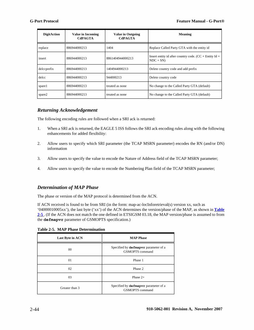
DigitAction Value in IncomingCdPAGTA
Value in OutgoingCdPAGTA
Meaning
replace 886944000213 1404 Replace Called Party GTA with the entity id
insert 886944000213 8861404944000213 Insert entity id after country code. (CC + Entity Id +NDC + SN)
delccprefix 886944000213 1404944000213 Delete country code and add prefix
delcc 886944000213 944000213 Delete country code
spare1 886944000213 treated as none No change to the Called Party GTA (default)
spare2 886944000213 treated as none No change to the Called Party GTA (default)
Returning Acknowledgement
The following encoding rules are followed when a SRI ack is returned:
1. When a SRI ack is returned, the EAGLE 5 ISS follows the SRI ack encoding rules along with the followingenhancements for added flexibility:
2. Allow users to specify which SRI parameter (the TCAP MSRN parameter) encodes the RN (and/or DN)information
3. Allow users to specify the value to encode the Nature of Address field of the TCAP MSRN parameter;
4. Allow users to specify the value to encode the Numbering Plan field of the TCAP MSRN parameter;
Determination of MAP Phase
The phase or version of the MAP protocol is determined from the ACN.
If ACN received is found to be from SRI (in the form: map-ac-locInforetrieval(s) version xx, such as‘04000010005xx’), the last byte (‘xx’) of the ACN determines the version/phase of the MAP, as shown in Table2-5 . (If the ACN does not match the one defined in ETSIGSM 03.18, the MAP version/phase is assumed to fromthe defmapvr parameter of GSMOPTS specification.)
Table 2-5. MAP Phase Determination
Last Byte in ACN MAP Phase
00 Specified by defmapvr parameter of aGSMOPTS command
01 Phase 1
02 Phase 2
03 Phase 2+
Greater than 3 Specified by defmapvr parameter of aGSMOPTS command
G-Port Protocol Feature Manual - G-Port®
2-44 910-5062-001 Revision A, November 2007
G-Port Message Handling
G-Port performs message handling in the following steps.
1. The message arrives at the EAGLE 5 ISSroute-on-gt. The EAGLE 5 ISS decodes the SCCP portion anduses the data to perform the G-Port selection based on the CDPA GT fields other than the ES and GTAI.The result of the selection provides a service indicator. The service indicator is G-Port if it is determinedthat MNP-SRF is required. If a G-Port selector does not match the incoming GT fields, the message is passedon for GTT selection.
2. MNP-SRF first decodes the Operation Code of the MAP message to distinguish the SRI message from therest. If the Operation Code is SRI and the OR Interrogation indicator is absent, and the GSMOPTS parameterSRIDN=TCAP, the MSISDN parameter is decoded from the MAP message. If the GSMOPTS parameterSRIDN=SCCP, or the message is not SRI, the digits available in the CDPAGTAI are used for databaselookup.
3. The decoded DN is conditioned to an international number before performing the RTDB lookup. Theconditioning performed depends on whether the digits are obtained from TCAP or MAP part of the message.
• If the digits are from the SCCP part, the number conditioning is based on SNAI value. First, RN prefixdeletion is performed, and conversion to an international number, based on its value. Conversion tointernational format is based on DEFCC and DEFNDC, as required. If the incoming number isCCRNDN, DEFCC and MULTCC are used to determine the Best Match CC to locate the RN digitsfor RN prefix deletion
• If the digits are from the MAP part, the number conditioning is based on NAI of MSISDN parameter.Prefix deletion is performed if MNPCRP is ON. The number is converted to an international number,if necessary. Conversion to international format is based on DEFCC and DEFNDC, as required. If theincoming number is international, DEFCC and MULTCC are used to determine if the format isCCRNDN or RNIDN. If a Best Match CC is located, then it is used to locate the RN digits for RNprefix deletion.
4. The RTDB database lookup is performed in two parts:
• The exception or individual number database is searched for a match. If the match is found, the dataassociated with this entry is considered.
• If the conditioned number is absent in the exception database, the number range database is searched.If the match is found, the data associated with this range entry is considered. If the search isunsuccessful, the result is no match.
5. If the number is found and a RN prefix is present for this entry, the following is performed:
• If the message is SRI, and MNPCRP is OFF, or if MNPCRP is ON and a HomeRN was not presentin the incoming DN (a HomeRN was not deleted from the SCCP CdPA/MAP MSISDN), then G-Port generates a SRI ack response with the RN prefix in the Routing Number parameter.
• If the message is non-SRI, and MNPCRP is OFF, or if MNPCRP is ON and a HomeRN was not presentin the incoming DN a HomeRN was not deleted from the SCCP CdPA), then G-Port uses the translationdata for the number to alter the CdPA digits and route the message to the destination.
Feature Manual - G-Port® G-Port Protocol
910-5062-001 Revision A, November 2007 2-45

• If the message is SRI or non-SRI, and MNPCRP is ON, and a HomeRN was present in the incomingDN (a HomeRN was deleted from the SCCP CdPA/MAP MSISDN), then G-Port generates UIM#1256, and the message shall fall through to GTT. In most network implementations, since the messagecontains RN+DN, this should cause a GTT failure, which will result in the EAGLE 5 ISS sending aUDTS to the originator if the Return Message on Error flag was set in the incoming UDT.
6. If the number is found and a SP entity is present for this entry, G-Port uses the SP translation data as thenumber to route the message to the destination. This is true whether or not MNPCRP feature is ON.
7. If the number is found and neither SP nor RN data is associated with it (this is a direct routing case withnumber not known to be ported), the following occurs:
• If the message is SRI, and MNPCRP is OFF, or if MNPCRP is ON and no HomeRN is present in theincoming DN (a HomeRN was not deleted from the SCCP CdPA/MAP MSISDN), and if the portabilitytype associated with the DN entry is other than 3 or 4 (including "no status"), then G-Port generatesa SRI ack response with the MSISDN in the Routing Number parameter. If the message is SRI, andMNPCRP is OFF, or if MNPCRP is ON and no HomeRN was present in the incoming DN ( a HomeRNwas not deleted from the SCCP CdPA/MAP MSISDN), and the portability type associated with theDN entry is either 3 or 4, then the SRI falls through to GTT (no SRI ack response is generated).
• If the message is non-SRI, and MNPCRP is OFF, or if MNPCRP is ON and no HomeRN is presentin the incoming DN (a HomeRN was not deleted from the SCCP CdPA), then the message falls throughto GTT.
• If the message is SRI or non-SRI, and MNPCRP is ON, and a HomeRN was present in the incomingDN (a HomeRN was deleted from the SCCPCdPA/MAP MSISDN), then G-Port generates UIM#1256, and the message falls through to GTT. In most network implementations, since the messagecontains RN+DN, this should cause a GTT failure, which results in the EAGLE 5 ISS sending aUDTS to the originator if the Return Message on Error flag was set in the incoming UDT.
8. GTT is performed on the message for any of these conditions:
• If G-Port is not required, or
• If the number is not found in the RTDB (both range and exception database).
G-Port SCCP Service Re-Route CapabilityThis feature is designed to handle and control re-routing of G-Port traffic from an affected node to alternate nodeswithin an operators network. This feature is an optional feature and doesn't affect the normal G-Port functionality.This feature consists to the following main functions:
• Service State
• MNP Re-Routing
• MNP Capability Point Codes
G-Port SCCP Service Re-Route Capability Feature Manual - G-Port®
2-46 910-5062-001 Revision A, November 2007
G-Port SCCP Service Re-Route Capability is not supported for the Prepaid SMS Intercept feature. G-Port SCCPService Re-Route Capability is supported for the IS-41 to GSM Migration feature.
Service State
Service state is part of the G-Port SCCP Service Re-Route Capability. Service state is used to indicate the currentstate of G-Port, either ONLINE or OFFLINE. Service state also gives the user the option to mark G-Port asOFFLINE or ONLINE based on the current behavior. If a G-Port problem is identified, G-Port can be markedOFFLINE to initiate the re-routing procedure. In the case when SCCP cards need to be reloaded for some reason,G-Port can be marked OFFLINE until enough cards are in-service and then bring G-Port ONLINE in a controlledfashion. This feature also provides the option to mark G-Port OFFLINE to perform a controlled re-routing duringthis state.
MNP Re-Routing
MNP Re-Routing is an optional feature and is enabled by defining a list of alternate PCs or by defining the GTToption. G-Port re-routing is activated by marking G-Port OFFLINE. When G-Port is OFFLINE and alternatePCs are provisioned, any messages destined for G-Port are re-routed to the available alternate PCs that are definedfor G-Port. If alternate PCs are not provisioned or none are available, then the GTT option is used. If the GTToption is set to YES, then messages destined for G-Port will fall through to GTT as part of the re-routing procedure.
Re-Routing is applied to all G-Port messages (based on SRVSEL). There is no distinction of DPC of the messages.The DPC of the message can be either True, Secondary, or Capability Point code.
MNP Capability Point Codes
Capability Point Codes (CPC) are also supported for G-Port. The use of MNP capability point code aids the adjacentnodes in knowing about G-Port outages. When G-Port is brought down though administrative commands, all trafficdestined to this G-Port node will generate a Transfer Prohibited (TFP) message to the adjacent node about the G-Port CPC. The TFP response to the adjacent node causes the traffic originating nodes to stop sending G-Port trafficto this node. All G-Port traffic coming into this node is sent to the alternate G-Port nodes. Adjacent nodes willinitiate route-set-test procedures after receipt of the TFP response.
If the messages are destined to the EAGLE 5 ISS true point code, then TFP messages are not generated when theG-Port service is OFFLINE. The originator would not be aware of the outage.
Once G-Port is back in service on the EAGLE 5 ISS, a Transfer Allowed (TFA) message is sent to the trafficadjacent nodes in response to route-set-test message. The traffic originating nodes will then start sending G-Porttraffic to the original G-Port node.
MNP Capability point codes can be provisioned when the G-Port feature is ON. There can be more than oneCapability Point Code assigned to G-Port CPC Type.
When the G-Port feature is turned ON and the G-Port service state is set to OFFLINE, the user can change theservice to ONLINE at any point. Once the feature is turned ONLINE, G-Port will start processing messages if atleast one SCCP card is IS-NR.
The G-Port service can be set to OFFLINE at any point. This causes the EAGLE 5 ISS to stop processing G-Port traffic and re-routing is performed.
The G-Port service state is persistent. Booting the OAM or all the SCCP cards will not change the service state.Commands must be used to change the service state.
G-Port supports up to 7 alternate PCs per domain. All 6 domains (ANSI, ITU-I, ITUN14, ITUN14 spare , ITU-Ispare and ITUN24) are supported. An entire set of alternate PCs are considered as a re-route set. A GTT option is
Feature Manual - G-Port® G-Port SCCP Service Re-Route Capability
910-5062-001 Revision A, November 2007 2-47

supported for G-Port re-route. When the G-Port service is OFFLINE, G-Port messages fall though to GTT basedon the GTT option. This option is set to YES by default.
G-Port SCCP Service Re-Route Capability Summary
If the G-Port service is not normal (because the RTDB is not in sync with MPS or if cards are misrouting G-Port messages) then the G-Port service state should be changed to OFFLINE.
Before changing G-Port service to OFFLINE, it should be decided what kind of re-routing will be used during theoutage. The EAGLE 5 ISS supports re-routing data to alternate point codes or falling through to GTT as twopossible options. Rerouting to alternate point code has priority over falling through to GTT. Examples of the twooptions follow:
Option 1
Define alternate point codes to re-route G-Port traffic. This is the recommended option. Up to 7 alternate G-Portnodes can be provisioned to re-route all the incoming G-Port traffic. Once provisioned, the G-Port service can bechanged to OFFLINE. This example has any incoming being G-Port traffic being load-shared to point codes basedon the relative cost.
chg-sccp-serv:serv=gport:pci1=1-1-1:rc1=10:pci2=2-2-2:rc2=10:pci3=3-3-3:rc3=10:pci4=4-4-4:rc4=10chg-sccp-serv:serv=gport:pci1=5-5-5:rc1=10:pci2=6-6-6:rc2=10:pci3=7-7-7:rc3=10:pci4=8-8-8:rc4=10chg-sccp-serv:serv=gport:state=offline
Option 2
With this option default GTT translations are provisioned for G-Port service. Then the chg-sccp-servcommand is used to provision GTT=YES. All G-Port messages will fall through to GTT. An example commandfollows:
chg-sccp-serv:serv=gport:gtt=yes (it is yes by default)
Once the G-Port re-routing data is provisioned, G-Port service can be changed to OFFLINE. At this point all G-Port traffic will be re-routed. The use can take necessary steps to correct the G-Port service on the node. Until allthe cards or enough cards are in active state with valid G-Port database, G-Port service should not be changed toONLINE.
Table 2-6 shows the actions taken when the G-Port service is offline, a message arrives at the affected noderequiring G-Port service, and SCCP cards are available.
Table 2-6. G-Port SCCP Service Re-Route Capability Summary
Result ofserviceselector
DPC Alternate point codedefined and available
GTT to beperformed as fall
through
Message Handling NetworkManagement
G-Port G-Port Capability PC Yes N/ARe-Route to alternatepoint code based onrelative cost
TFP concerningCPC
G-Port G-Port Capability PC No* Yes Fall through to GTTand perform GTT
TFP concerningCPC
G-Port SCCP Service Re-Route Capability Feature Manual - G-Port®
2-48 910-5062-001 Revision A, November 2007

Result ofserviceselector
DPC Alternate point codedefined and available
GTT to beperformed as fall
through
Message Handling NetworkManagement
G-Port G-Port Capability PC No* NoGenerate UDTS (returncause = networkfailure)
TFP concerningCPC
G-Port G-Port Capability PC Not Defined Yes Fall through to GTTand perform GTT
TFP concerningCPC
G-Port G-Port Capability PC Not Defined NoGenerate UDTS (returncause = no xlation forthis addr)
TFP concerningCPC
Not G-Port G-Port Capability PC N/A N/A Perform appropriateService/GTT None
G-Port True or Secondary PC ornon-G-Port CPC Yes N/A
Re-Route to alternatepoint code based onrelative cost
None
G-Port True or Secondary PC ornon-G-Port CPC No* No
Generate UDTS (returncause = networkfailure)
None
G-Port True or Secondary PC ornon-G-Port CPC No* Yes Fall through to GTT
and perform GTT None
G-Port True or Secondary PC ornon-G-Port CPC Not Defined Yes Fall through to GTT
and perform GTT None
G-Port True or Secondary PC ornon-G-Port CPC Not Defined No
Generate UDTS (returncause = no xlation forthis addr)
None
Not G-Port True or Secondary PC ornon-G-Port CPC N/A N/A Perform appropriate
Service/GTT None
* Alternate point codes are defined and unavailable (prohibited or congested).
Table 2-7 shows the actions of LIM re-route functionality when SCCP cards are unavailable or down.
Table 2-7. G-Port LIM Re-Route Message Handling Summary
RoutingIndicator in
IncomingMessage
DPC Full or PartialFailure
G-Port ServiceStatus
Message Handling NetworkManagement
rt-on-gt G-Port Capability PC Full N/A Generate UDTS TFP concerningCPC, UPU
rt-on-gt Non G-Port Capability PC Full N/A Generate UDTS TFP concerningCPC, UPU
rt-on-gt True PC Full N/A Generate UDTS UPU
rt-on-gt G-Port Capability PC Partial* ONLINE Generate UDTS None
rt-on-gt True PC or non G-PortCapability PC Partial* ONLINE Generate UDTS None
Feature Manual - G-Port® G-Port SCCP Service Re-Route Capability
910-5062-001 Revision A, November 2007 2-49

RoutingIndicator in
IncomingMessage
DPC Full or PartialFailure
G-Port ServiceStatus
Message Handling NetworkManagement
rt-on-gt G-Port CPC Partial* OFFLINE Generate UDTS TFP concerningCPC, UPU
rt-on-gt True PC or non-G-PortCPC Partial* OFFLINE Generate UDTS None
* It is considered a partial failure if some SCCP cards are available but overloaded.
Prepaid SMS Intercept Protocol
Main Functions
Prepaid SMS Intercept performs the following main functions:
Message Discrimination
Prepaid SMS Intercept uses the G-Port message selection methods to determine whether the message shouldreceive PPSMS/G-Port service versus GTT.
If the incmoning selectors match a SRVSEL entry and the entry has SERV=SMSMRPPSMS is performed, and ifno match is found in SRVSEL table then GTT is performed. If the SSN is for HLR, G-Port is performed. If theSSN is for MSC, PPSMS is performed, and if the SSN is for neither, GTT is performed. Next, the MAP OperationCode received in the message is examined. Only Mobile originated forward short message calls receive PPSMSservice. Other messages fall through to GTT. After MAP operation code discrimination, PPSMS providesdiscrimination based on SCCPCGPAGTA digits. This allows the operator to decide whether messages from certainCGPAs will receive PPSMS service or fall through to GTT, even if they meet all of the previous service selectioncriteria.
Number Conditioning
The RTDB stores international MSISDNs only. The received MSISDN number or SCCPCDPA digits may needto be converted to an international number to do a database lookup.
When PPSMS is required to be performed on a message and the number is not international (that is, the NAI ofMSISDN number is “National (Significant) Number” or “Subscriber Number)”, the National/Local to Internationalnumber is triggered.
For a National (Significant) Number, the received MSISDN digits are prepended with the default country codeand for a Subscriber number, the MSISDN digits are prepended with the default country code and the defaultnetwork code. If the NAI is neither International or Subscriber, the message is treated as National.
Prepaid Screening
Once the number is conditioned, the PPSMS feature performs a database search to determine if the MSISDNbelongs to a prepaid subscriber. This is determined by the pt field associated with the database entry for theMSISDN. PPSMS performs the database lookup using the international MSISDN. The individual number database
Prepaid SMS Intercept Protocol Feature Manual - G-Port®
2-50 910-5062-001 Revision A, November 2007

is searched first, and if the number is not found, then the number range database is searched. If a match is not foundin individual nor range-based database, then GTT is performed on the message. In case of MSISDN numbers inthe PPSMS database being odd and the last digit of the decoded MSISDN from the FSM being 'zero', PPSMS firstperforms a database lookup once using the even number. If no match is found, then PPSMS performs the databaselookup again, now using the odd number (without last digit).
Message Relay to IN Platform
If the database search determines that the subscriber is prepaid, the message is redirected to one of the two INplatforms using the translation data in the GSM options table. If the routing indicator in the IN platform translationdata is route-on-SSN, the mated application table is accessed to determine the point code/subsystem status for theIN platform, and if it has a mate. The SCCPCDPAGTA should not be changed as a result of this operation. If theRI in the translation data indicates route-on-GT, and if the Intermediate GTTLoad Sharing feature is turned on,the mated relay node table is accessed to determine the point code status and if the IN platform has a mate.Subsystem status is not maintained in the mated relay node.
SMS Prepaid Intercept Message Handling
PPSMS performs message handling in the following steps.
1. The message arrives at the EAGLE 5 ISSroute-on-gt. The EAGLE 5 ISS decodes the SCCP portion anduses the data to perform the G-Port selection based on the CDPANP, NAI, TT, SSN, and GTI. The result ofthe selection provides a service indicator. The service indicator is SMSMR if PPSMS is required. If aSMSMR selector does not match the incoming GT fields, the message is passed on for GTT selection.
2. If Item 1 indicates PPSMS is required, and the message is not a UDTS generated by EAGLE 5 ISS, theEAGLE 5 ISS performs PPSMS service.
3. If the message is a UDTS generated by the EAGLE 5 ISS, then regular GTT is performed on the message.
4. If the EAGLE 5 ISS receives a UDTS message from another node, it is treated in the same manner as anyother message. If GTT is indicated, then the UDTS translation is based on the CDPAGTA, and the messageis routed to the translated address. If GTT is not indicated, the UDTS is through switched via MTP routing.The one exception is that if translation fails on the UDTS, the EAGLE 5 ISS will not generate anotherUDTS to send to the originator of the UDTS that failed.
5. The TCAP/MAP portion of the message is decoded by PPSMS. If the message is not a TC_BEGIN, themessage falls through to GTT.
6. If the message is a TC_BEGIN, PPSMS decodes the Operation Code of the MAP message to distinguishMO_FSMs from the rest. If the OpCode is not FSM (MAP version 1 or 2) or MO_FSM (MAP version 3),the message falls through to GTT.
7. If the OpCode is FSM (MAP version 1 or 2) or MO_FSM (MAP version 3), the MAP portion of the messageis decoded and searched for a MSISDN tag. If a MSISDN tag is not found, the message falls through toGTT. For version 3 MO_FSMs, the SMRPOA parameter would contain the MSISDN tag. For version 1 or2 FSMs, a MSISDN tag is found if the message is mobile originated. If it is mobile terminated, aMSISDN tag is not found and the message falls through to GTT.
Feature Manual - G-Port® Prepaid SMS Intercept Protocol
910-5062-001 Revision A, November 2007 2-51

8. If the MSISDN is found in Item 7 , the SCCPCGPAGTA is compared to the IN platform GTAs provisionedin the GSMOPTS table. If the decoded GTA matches one of the IN platform Gas, the message falls throughto GTT.
9. If the SCCPCGPAGTA in Item 8 does not match any of the IN platform GTAs, the MSISDN from theMAP portion is decoded and conditioned to an international number before performing the lookup. Thenumber conditioning is based on NAI of MSISDN parameter. The number is converted to an internationalnumber, if necessary.
10. The database lookup is performed in two parts:
• The exception or individual number database is searched for a match. If the match is found, the dataassociated with this entry is considered.
• If the conditioned number is absent in the exception database, the number range database is searched.If the match is found, the data associated with this range entry is considered. If the search isunsuccessful, the result is no match.
In case of MSISDN numbers in the PPSMS database being odd and the last digit of the decoded MSISDNfrom the FSM being 'zero', PPSMS first performs database lookup once using the even number. If no matchis found then PPSMS performs the database lookup again, using the odd number (without last digit).
11. If a number match is found as a result of the search, the Portability Type (pt) field associated with the entryis examined.
• If the pt is prepaid1 or prepaid2, the IN platform translation information (PC and RI) associated withthat type is retrieved from the GSM options. If the RI is SSN, the information is used to access themated application (MAP) table for point code status and to see if the selected IN platform is in a loadsharing relationship with another. If the RI is GT, and if the IGTTLoad Sharing feature is on, the matedrelay node table is used for this purpose. If the point code is available, the message is routed the INplatform. If the point code is in a load sharing relationship with other point codes, messages are equallydivided between them.
• If the pt is not prepaid1 nor prepaid2, the message falls through to GTT.
12. If a number match is not found as a result of the search in Item 10 , the message falls through to GTT.
PPSMS Without G-Port MNP
The G-PortFAK must be enabled in order to activate the PPSMS feature. PPSMS can be used without using G-PortMNP. The PPSMS service and GPORT service and mutually exclusive for a particular subsystem.
Service selector commands are used to provision PPSMS service. serv=smsmr is used for PPSMS Service. Thisservice can be assigned to ITU selectors only. SNP must be set to E.164 and all values of SNAI are supported.Refer to EAGLE 5 ISS G-Port Service Selector Commands for more information.
Prepaid SMS Intercept Protocol Feature Manual - G-Port®
2-52 910-5062-001 Revision A, November 2007
MO-based GSM SMS NPThe MO-based GSM SMS NP feature provides network information to the short message service center(SMSC) for subscribers using the GSM network. This information allows the SMSC to select a protocol to deliverSMS messages to the called party.
The MO-based GSM SMS NP feature:
• Intercepts SMS messages after they have undergone Prepaid SMS (PPSMS) and Portability Check for MobileOriginated SMS (MNPSMS) processing and before they reach the SMSC.NOTE: The MO-based GSM SMS NP feature does not require the PPSMS or MNPSMS features tobe enabled.
• Decodes the TCAP/MAP message destination address and performs lookup in the number portability (NP)database
• Modifies the destination address in the TCAP message with directory number (DN) porting information,and
• Relays the message to the SMSC
The SMSC uses the DN porting information to determine whether to forward the message to other operators or toprocess the message for an in-network subscriber.
The MO-based GSM SMS NP feature applies to ForwardSM SMS MSUs with ITU TCAP/MAP for either ITUor ANSI MTP messages.
Operations
The MO-based GSM SMS NP feature provides the following configurable options for controlling the processingof GSM SMS messages:
• Modifying SMS destination address information for processing
• Outbound digit format
• When an NP DB lookup is considered to be successful
• Handling of sub address field in destination address
Feature Control Requirements
The MO-based GSM SMS NP feature has the following feature control requirements:
• A FAK for part number 893-0194-01
• The G-Port feature must be enabled and turned on before the feature can be enabled and turned on.
• The feature cannot be enabled if LNP is enabled.
• A temporary FAK cannot be used to enable the feature.
• The feature cannot be turned off after it has been turned on.
Feature Manual - G-Port® MO-based GSM SMS NP
910-5062-001 Revision A, November 2007 2-53

System Options for MO-Based GSM SMS NP
The system level options that control the MO-Based GSM SMS NP feature are stored in the GSMOPTS databasetable. The MO_Based GMS SMS NP feature must be enabled before the GSMOPTS table can be provisioned.
The content of the GSMOPTS table is used to help perform number conditioning, response generation, and otherfeature-specific options. Table 2-8 shows the options stored in the GSMOPTS table, their possible values, andthe action taken for each value.
Table 2-8. MO-Based GSM SMS NP Options
GSMOPTS Value Action in the EAGLE 5 ISS
MOSMSDNFMT RN Same as G-Port general action.
RNDN (default)
CCRNDN
MOSMSTYPE SP When the lookup in the NPDB has entitytype=SP, then the lookup is considered successful.
RN When the lookup in the NPDB has entitytype=RN, then the lookup is considered successful.
SPRN (default) When the lookup in the NPDB has entitytype=SP or RN, then the lookup is considered successful.
ALL When the lookup in the NPDB has entitytype=SP or RN or no_entity, then the lookup is consideredsuccessful.
MOSMSNAI NAT The CdPN is treated as National number for lookup in the NPDB. When SNAI=NAT, the CC will beadded to the DN before lookup in the NP database
INTL (default) When SNAI=INTL, no number conditioning is required before lookup in the database.
NAI The NAI from the MO_SMS message is used for conditioning before lookup in database.
• If the NAI is INTL, then NP lookup is performed immediately.
• If the NAI is any other value, then the number is considered to be in national format. The CCis added before NP lookup is performed.
MOSMSSA YES The subaddress is searched in the B party number. If the subaddress (identified by "#" being presentin the B party number) is found, it is removed before NPDB lookup is performed.
NO (default) No subaddress is searched for in the B party number from the TCAP part.
MOSMSDNNAI None (default) The NAI is same as the NAI in the incoming message.
0–15 The value to be encoded in the outgoing message.
MOSMSFWD YES If the MO-SMS TCAP called party number is modified, then the MO-SMS message will beredirected,by modifying the SCCP CDPA, to the GTA identified in the MOSMSGTA field.
This option cannot be set to YES unless the MOSMSGTA option has a valid value specified.
NO (default) No MO-SMS forward will be performed.
MOSMSGTA 5–21 digits This field is used to replace the SCCP CDPA in the MO-SMS message. If the MO-SMS TCAP calledparty number is modified, then the MO-SMS message will be redirected by modifying the SCCP.
This option cannot be specified unless the a GTA with the same value has been provisioned in theGTT translation table. For more information about the GTT translation table, refer to the DatabaseAdministration Manual - GTT.
MO-Based GSM SMS NP Protocol Handling
After the MO-Based GSM SMS NP feature has been enabled and turned, it provides the following protocolhandling:
• The MO-Based GSM SMS NP feature traps the MO_SMS message and performs NPDB lookup based onthe B number from the TCAP sm-RP-UI parameter. If the entity type is the same as the value of the
MO-based GSM SMS NP Feature Manual - G-Port®
2-54 910-5062-001 Revision A, November 2007

MOSMSTYPE option in the GSMOPTS table, then this feature modifies the outgoing MO_SMS based onthe value of the MOSMSDNFMT option.
• When the outgoing MO-SMS is modified, the NAI is based on the value of the MOSMSNAI parameter inthe GSMOPTS table.
• The MO-Based IS41 SMS NP feature performs SCCPCDPAGTA lookup against the SMSC list maintainedby the STP. If the lookup is not successful, the MSU falls through to GTT handling.
• When both the MO-Based GMS SMS NP feature and the Portability Check for MO-SMS feature are enabled:
— Both features must have the same service-selector service.
— The MO-Based GSM SMS NP feature processes an MSU only when the MSU has passed theprocessing by the Portability Check for MO_SMS feature and no NACK has been sent.
• The MO-Based GSM SMS NP feature is required only for MO_SMS messages with SMS-Submit and SMS-Command.
• The number conditioning is based on the value of the MOSMSNAI option:
— If MOSMSNAI=NATL, then the number is treated like a national number: DEFCC is prepended beforeperforming lookup in the NPDB.
— If MOSMSNAI=INTL, then the number is treated like an international number: this number is usedfor lookup in the NPDB.
— If MOSMSNAI=NAI, then the conditioning is based on the NAI value from the TCAP part.
— If MOSMSNAI=NAI and TCAP NAI is not INTL, then the number is considered to be international.
• For messages handled within this feature, the SCCP CDPA is always used to route the message.
• If the MOSMSTYPE=ALL, MOSMSDNFMT=RN, and the NPDB lookup has no entity assigned to the DN,then the MO_SMS message is not modified.
• If the MOSMSSA=YES, then the subaddress is searched and removed from MAP called Party number forNPDB lookup. The subaddress is not removed from the final MO_SMS message.
• If the number of called party digits in the modified MO_SMS message is greater than 20, then the digits arenot modified and the original message is routed to the SMSC based on SCCPCDPA.
• The MO-based GSM SMS NP feature considers a successful NPDB lookup with entity_type=RN andportability-type=0 to be entity_type=SP, if the IS41-GSM Migration feature is enabled. (When the IS41-GSM Migration feature is enabled, entity_type=RN, and portability-type=0, the subscriber is considered tobe migrated, and therefore is considered to be local (in-network, SP) for the MO-based IS41 SMS NP feature.)
• If the MOSMSFWD=Yes and the MO-SMS TCAP called-party number is modified after successful RTDBlookup, then the MO-SMS message is redirected to the GTA identified in the MOSMSGTA field bymodifying the SCCPCDPA.
Feature Manual - G-Port® MO-based GSM SMS NP
910-5062-001 Revision A, November 2007 2-55

MO-based GSM SMS NP Feature Manual - G-Port®
2-56 910-5062-001 Revision A, November 2007

3
EAGLE 5 ISS G-Port Commands
Introduction..........................................................................................................................................................3-1EAGLE 5 ISS Commands for G-Port...................................................................................................................3-1
System Debug Services (SDS) Commands...................................................................................................3-1EAGLE 5 ISS Options Commands...............................................................................................................3-2EAGLE 5 ISS G-Port System Options Commands.......................................................................................3-3EAGLE 5 ISS G-Port Service Selector Commands......................................................................................3-4EAGLE 5 ISS G-Port SCCP Service Commands.........................................................................................3-7EAGLE 5 ISS Feature Key Control Commands...........................................................................................3-9EAGLE 5 ISS Database Commands...........................................................................................................3-10
Maintenance and Measurements User Interface.................................................................................................3-10Maintenance Commands.............................................................................................................................3-10
IntroductionThis section describes the user interface and provides command examples needed to administer the G-Port feature.The exact command syntax, specifications, and command classes are provided in the Commands Manual. Thecommand examples are provided to convey the intention of the user interface requirements.
EAGLE 5 ISS Commands for G-PortThis section includes the EAGLE 5 ISS commands that are either entirely new or modified for the G-Port feature.This chapter contains a brief description of the functions they provide and appropriate examples of their use.
The command examples in this chapter illustrate the requirements and provide suggestions for suitable names andoutput. Complete descriptions of these commands, however, are shown in detail in the Commands Manual,including parameter names, valid values, and output examples for the commands.
System Debug Services (SDS) Commands
The following section describes SDS command ent-trace used with G-Port.
910-5062-001 Revision A, November 2007 3-1

MSU Trap and Trace Command
G-Port uses the existing ent-trace command to provide a trap-and-trace function for MSUs on the SCCP card.G-Port also introduces a new trigger so the user can trigger on DN and IMSI.
The user can create a MSU trigger on the SCCP card on one or more criteria (both old and new) defined in thefollowing using the ent-tracecommand. When multiple trigger criteria are entered, the MSU is trapped whenany one of the criteria are satisfied.
CAUTION: As with other debug commands, this command can cause OAM to reset if toomany MSUs are trapped.
• RN or SP address (Entity ID) - Use this new criterion to trap messages immediately after performing theRTDB database lookup. If the RN or SP obtained from the database lookup matches the Entity ID provisionedin the command, the message is trapped. This parameter supports a variable number of hexadecimal digitsfrom 1 to 15 digits, and the Entity ID specified must be the one stored in the G-PortRTDB.
• E.164 MSISDN number (DN) – Use this criterion to trap messages immediately before performing a G-Port search based on the MSISDN numbers defined in the G-PortRTDB. This parameter accepts a range ofdigits, from 5 to 15. The number specified must be an International E.164 number (MSISDN or EntityNumber).
• Global Title digits (GT) – Use this criterion to trap messages based on CdPA Global Title Address (thatis, either MSISDN (+ST) number or RN + MSISDN (+ST)) present in the SCCP part of the message.
• Origination point code (SSPI/SSPN) – Use this criterion to trap messages based on CgPASPC present inthe SCCP part of the message. If no point code is present in the CgPASPC, the criteria is matched with theOPC present in the MTP part of the message.
A trace must still be set on all SCCP cards; specify card=sccp-all. Use a repetition parameter (rep) to controlthe number of MSUs that are trapped.
MSUs that satisfy any trigger criteria are trapped on the SCCP card, are forwarded to OAM, and are displayed.Refer to Commands Manual for a complete description of the ent-trace command.
EAGLE 5 ISS Options Commands
The STP system options commands (stpopts) change and display STP wide options in the EAGLE 5 ISSdatabase. It has two variations, each of which is described in the following: chg-stpopts and rtrv-stpopts. For further details on these commands, refer to the Commands Manual.
• chg-stpopts: Change STP System Options Command – The chg-stpopts command changes STPsystem options in the database. This command updates the STPOPTS table. The defcc and defndcparameters are used to convert non-international numbers received in the MSU to an international number.The parameters can only be changed if the G-Port (FAK), G-Flex, or INP feature bit is ON. A commandexample follows:
chg-stpopts:defcc=333: defndc=22345
Where:
defcc={1-3 digits, none} E164 Default Country Code
defndc={1-5digits, none} E164 Default National Destination Code
EAGLE 5 ISS Commands for G-Port Feature Manual - G-Port®
3-2 910-5062-001 Revision A, November 2007

• rtrv-stpopts: Retrieve STP System Options Command – The rtrv-stpopts command is used toretrieve all STP options from the database. This command updates the STPOPTS table. The defcc anddefndc parameters are the additional options displayed when the G-Port (FAK), G-Flex, or INP featurebit is ON.
EAGLE 5 ISS G-Port System Options Commands
The G-Port system options (gsmopts) commands change and display G-Port-specific system options in theEAGLE 5 ISS database. It has two variations, each of which is described in the following: chg-gsmopts andrtrv-gsmopts. For further details on these commands, refer to the Commands Manual.
• chg-gsmopts: Change G-Port System Options Command – The chg-gsmopts command changes G-Port-specific system options in the database. This command updates the GSMOPTS table. The defaultparameters are always overwritten when specified.
Command: chg-gsmopts Class = DATABASE
Parameter Optional/Mandatory
Range Description
defmapvr Optional 1-3 Default MAP version
gsm2is41 Optional 1-15 digits, none GSM to IS41 migration prefix
is412gsm Optional 1-15 digits, none IS-41 to GSM migration prefix.
msisdntrunc Optional 1 digit (0-5) MSISDN Truncation digits
msrndig Optional rn, rnidn, ccrndn RN used as-is or with MSISDN
msrnnai Optional 1-7 NAIV for the MSRN
msrnnp Optional 0-15 Numbering plan for the MSRN
multcc Optional 1 to 3 digits (0-9, a-f, or A-F) Multiple Country Code
nmultcc Optional 1 to 3 digits (0-9, a-f, A-F, orNONE) New Multiple Country Code
nnpsmsgta Optional 1-15 digits, none New entity address of PPSMS Phase1
ppsmsgta Optional 1-15 digits Entity address of PPSMS Phase 1
ppsmspci1 Optional zone, area, id, none ITUPC of IN platform 1 for PPSMSPhase 1
ppsmspci2 Optional zone, area, id, none ITUPC of IN platform 2 for PPSMSPhase 1
ppsmspcn1 Optional nnnn, gc, m1, m2, m3, m4, none ITUPC of IN platform 1 for PPSMSPhase 1
ppsmspcn2 Optional nnnn, gc, m1, m2, m3, m4, none ITUPC of IN platform 2 for PPSMSPhase 1
Feature Manual - G-Port® EAGLE 5 ISS Commands for G-Port
910-5062-001 Revision A, November 2007 3-3

Parameter Optional/Mandatory
Range Description
ppsmsri1 Optional gt, ssn RI of IN platform 1 for PPSMS Phase1
ppsmsri2 Optional gt, ssn RI of IN platform 2 for PPSMS Phase1
serverpfx Optional 1-4 digits, none Server SRI prefix
srfaddr Optional 1-15 digits, none Entity address of MNP_SRF node
srfnai Optional 0-127 NAIV of the MNP_SRF
srfnp Optional 0-15 Numbering plan value of theMNP_SRF Network Code
sridn Optional tcap, sccp SRIDN location
Command examples follow.
• chg-gsmopts:srfnai=4:srfnp=2:srfaddr=331111111111• chg-
gsmopts:srfaddr=333221234567890:msrndig=rn:srfnai=1:srfnp=1:msrnnai=4 :msrnnp=10
• chg-gsmopts:ppsmspcn2=234:ppsmsri2=ssn• chg-gsmopts:sridn=tcap chg-gsmopts:is412gsm=0123456789abcde
rtrv-gsmopts: Retrieve G-Port System Options Command
The rtrv-gsmopts command displays all G-Port-specific system options from the database.
The following G-Port options are displayed.
GSM OPTIONS ----------------------- MSRNDIG = 7 DEFMAPVR = 2 SRIDN = TCAP IS412GSM = 0123456789abcde PPSMSRI1 = SSN PPSMSRI2 = GT PPSMSPCI1 = 1-1-1 PPSMSPCN2 = ----------- PPSMSGTA = 1112223333, 2223334444, ABCDEF123456ABC MIGRPFX = SINGLE GSM2IS41 = NONE
EAGLE 5 ISS G-Port Service Selector Commands
The G-Port service selector (srvsel) commands are used to provision new selectors for the G-Port service,providing greater flexibility when provisioning the type of messages that require G-Port processing. There are fourvariants, each of which is described in the following sections: ent-srvsel, chg-srvsel, dlt-srvsel,and rtrv-srvsel. For further details on the EAGLE 5 ISSG-Port service selector commands (such as commandrules and output format), refer to the Commands Manual.
EAGLE 5 ISS Commands for G-Port Feature Manual - G-Port®
3-4 910-5062-001 Revision A, November 2007

ent-srvsel: Enter G-Port Service Selectors Command – The ent-srvsel command specifies that theapplicable G-Port service selectors indicating G-Port processing are required. The available parameters follow:
Command : ent-srvsel Class = DATABASE
Parameter Optional/Mandatory
Range Description
gti, gtia, gtii, gtin, gtin24 Mandatory 2, 4 Global Title Indicator
serv Mandatory gport, gflex, inpq, inpmr, eir, smsmr,mnpsms, idpd, idpr, mnp GSM service
snai Mandatory sub, natl, intl, rnidn, rnndn, rnsdn,ccrndn Service Nature Of Address Indicator
snp Mandatory e164, e212, e214 Service Numbering Plan
ssn Mandatory 0-255, * Subsystem Number
tt Mandatory 0-255 Translation Type
nai Optional sub, rsvd, natl, intl Nature Of Address Indicator
naiv Optional 0-127 NAI Value
np Optional e164, generic, x121, f69, e210, e212,e214, private Numbering Plan
npv Optional 0-15 Numbering Plan Value
chg-srvsel: Change G-Port Service Selector Command – The chg-srvsel command specifies the applicableG-Port selectors required to change an existing G-Port selector entry. The available parameters follow:
Command : chg-srvsel Class = DATABASE
Parameter Optional/Mandatory
Range Description
gti, gtia, gtii, gtin, gtin24 Mandatory 2, 4 Global Title Indicator
ssn Mandatory 0-255, * Subsystem Number
tt Mandatory 0-255 Translation Type
nai Optional sub, rsvd, natl, intl Nature Of Address Indicator
naiv Optional 0-127 NAI Value
np Optional e164, generic, x121, f69, e210, e212,e214, private Numbering Plan
npv Optional 0-15 Numbering Plan Value
nserv Optional gport, gflex, inpq, inpmr, eir, smsmr,mnpsms, idpd, idpr, mnp New GSM service
nsnai Optional sub, natl, intl, rnidn, rnndn, rnsdn,ccrndn
New Service Nature Of AddressIndicator
Feature Manual - G-Port® EAGLE 5 ISS Commands for G-Port
910-5062-001 Revision A, November 2007 3-5

Parameter Optional/Mandatory
Range Description
nsnp Optional e164, e212, e214, none New Service Numbering Plan
dlt-srvsel:Delete G-Port Service Selector Command – The dlt-srvsel command deletes a G-Port serviceselector. The available parameters follow:
Command: dlt-srvsel Class = DATABASE
Parameter Optional/Mandatory
Range Description
gti, gtia, gtii, gtin, gtin24 Mandatory 2, 4 Global Title Indicator
ssn Mandatory 0-255, * Subsystem Number
tt Mandatory 0-255 Translation Type
nai Optional sub, rsvd, natl, intl Nature Of Address Indicator
naiv Optional 0-127 NAI Value
np Optional e164, generic, x121, f69, e210, e212,e214, private Numbering Plan
npv Optional 0-15 Numbering Plan Value
rtrv-srvsel: Retrieve G-PortService Selector Command – The rtrv-srvsel command displays a list ofadministered G-Port service selector combinations. All output is sorted first by service, then by global title domain(ANSI first, followed by ITU), GTI, translation type, numbering plan, and by the nature of address indicator. Theoutput can be filtered by specifying any optional parameter. The available parameters follow:
Command : rtrv-srvsel Class = DATABASE
Parameter Optional/Mandatory
Range Description
gti, gtia, gtii, gtin, gtin24 Optional 2, 4 Global Title Indicator
nai Optional sub, rsvd, natl, intl Nature Of Address Indicator
naiv Optional 0-127 NAI Value
np Optional e164, generic, x121, f69, e210, e212,e214, private Numbering Plan
npv Optional 0-15 Numbering Plan Value
serv Optional gport, gflex, inpq, inpmr, eir, smsmr,mnpsms, idpd, idpr, mnp GSM service
snai Optional sub, natl, intl, rnidn, rnndn, rnsdn,ccrndn Service Nature Of Address Indicator
snp Optional e164, e212, e214 Service Numbering Plan
ssn Optional 0-255, * Subsystem Number
EAGLE 5 ISS Commands for G-Port Feature Manual - G-Port®
3-6 910-5062-001 Revision A, November 2007

Parameter Optional/Mandatory
Range Description
tt Optional 0-255 Translation Type
EAGLE 5 ISS G-Port SCCP Service Commands
The sccp-serv commands allow for services to be taken ON and OFF line and their processing load to be shiftedto other designated nodes. These commands also support the assignment of PCs to PC groups used for G-Port re-route assignment. There are three variants, each of which is described in the following sections: chg-sccp-serv, dlt-sccp-serv, and rtrv-sccp-serv.
Entries (using the chg-sccp-serv command) are provisioned in the SCCP-SERV table, and are shown by thertrv-sccp-serv command output. This reduces the maximum number of entries that the MRN table cancontain by the number of entries shown in the rtrv-sccp-serv command output. For more information onprovisioning MRN tables, refer to the Database Administration Manual - Global Title Translations.
For further details on the EAGLE 5 ISSG-PortSCCP service commands (such as command rules and outputformat), refer to the Commands Manual.
chg-sccp-serv: Change G-PortSCCP Service Command – The chg-sccp-serv command is used to addpoint codes to an existing service group, or to change the Relative Cost (RC) of existing point codes in a group.SCCP Service groups are organized by service (G-Flex or G-Port) and point code network type (ANSI, ITU-I,Spare ITU-I, ITU-N, Spare ITU-N, or ITUN-24). Up to seven PCs may be in a network type grouping for servicere-route load sharing. This command allows for additions/modifications of up to 4 PCs at once. The point codeparameters support the Spare Point Code subtype prefix s- for ITU-I and ITU-N point codes. The availableparameters follow:
Command : chg-sccp-serv Class = DATABASE
Parameter Optional/Mandatory
Range Description
serv Mandatory gport, gflex, mnp Service
state Optional offline, online Status
gtt Optional no, yes Global Title Translation
pc1, pca1, pci1, pcn1,pcn241 Optional Refer to Commands Manual Post GTT-translated PC
rc1 Optional 00-99 Relative Cost
pc2, pca2, pci2, pcn2,pcn242 Optional Refer to Commands Manual Post GTT-translated PC
rc2 Optional 00-99 Relative Cost
pc3, pca3, pci3, pcn3,pcn243 Optional Refer to Commands Manual Post GTT-translated PC
rc3 Optional 00-99 Relative Cost
pc4, pca4, pci4, pcn4,pcn244 Optional Refer to Commands Manual Post GTT-translated PC
Feature Manual - G-Port® EAGLE 5 ISS Commands for G-Port
910-5062-001 Revision A, November 2007 3-7
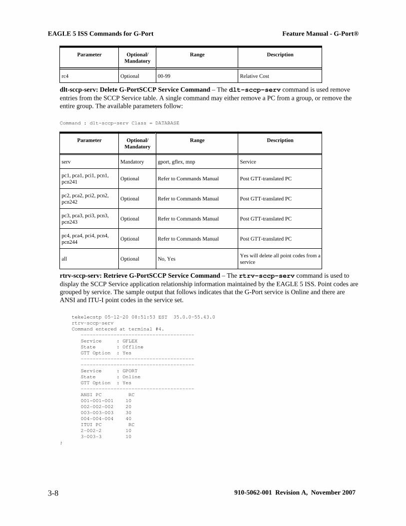
Parameter Optional/Mandatory
Range Description
rc4 Optional 00-99 Relative Cost
dlt-sccp-serv: Delete G-PortSCCP Service Command – The dlt-sccp-serv command is used removeentries from the SCCP Service table. A single command may either remove a PC from a group, or remove theentire group. The available parameters follow:
Command : dlt-sccp-serv Class = DATABASE
Parameter Optional/Mandatory
Range Description
serv Mandatory gport, gflex, mnp Service
pc1, pca1, pci1, pcn1,pcn241 Optional Refer to Commands Manual Post GTT-translated PC
pc2, pca2, pci2, pcn2,pcn242 Optional Refer to Commands Manual Post GTT-translated PC
pc3, pca3, pci3, pcn3,pcn243 Optional Refer to Commands Manual Post GTT-translated PC
pc4, pca4, pci4, pcn4,pcn244 Optional Refer to Commands Manual Post GTT-translated PC
all Optional No, Yes Yes will delete all point codes from aservice
rtrv-sccp-serv: Retrieve G-PortSCCP Service Command – The rtrv-sccp-serv command is used todisplay the SCCP Service application relationship information maintained by the EAGLE 5 ISS. Point codes aregrouped by service. The sample output that follows indicates that the G-Port service is Online and there areANSI and ITU-I point codes in the service set.
tekelecstp 05-12-20 08:51:53 EST 35.0.0-55.43.0 rtrv-sccp-serv Command entered at terminal #4. -------------------------------------- Service : GFLEX State : Offline GTT Option : Yes -------------------------------------- -------------------------------------- Service : GPORT State : Online GTT Option : Yes -------------------------------------- ANSI PC RC 001-001-001 10 002-002-002 20 003-003-003 30 004-004-004 40 ITUI PC RC 2-002-2 10 3-003-3 10;
EAGLE 5 ISS Commands for G-Port Feature Manual - G-Port®
3-8 910-5062-001 Revision A, November 2007

EAGLE 5 ISS Feature Key Control Commands
These commands are used to enable, update, view, and control the G-Port, MNPCRP, and PPSMS features on theEAGLE 5 ISS. A separate Feature Access Key is required to turn-on each feature. Features must be purchased inorder to have access to the Feature Access Key, which must be used when enabling these features.
There are temporary keys associated with the PPSMS nd MNPCRP features. There is no temporary key associatedwith the G-Port feature and once it is turned-on, it cannot be turned off. There are two steps that will be taken toturn the G-Port feature on. The first step is to enable the feature. The second step is to turn the status to on.
Additional verifications are done to ensure the correct hardware is present in the system. These checks includeverifying that the GTT bit is on and that there are no SCCPGLP cards provisioned. Refer to the Commands Manualfor details of this command.
Part number 893017201 is used to enable the G-Port feature on the EAGLE 5 ISS.
Part number 893007001 is used to enable the MNPCRP feature on the EAGLE 5 ISS.
Part number 893006701 is used to enable the PPSMS feature on the EAGLE 5 ISS.
enable-ctrl-feat: EnableControl Feature Command –The enable-ctrl-feat command is used fortemporary (PPSMS, MNPCRP) and permanent enabling of the features. An example of the command using theG-Port part number follows:
enable-ctrl-feat:partnum=893017201:fak=<Feature Access Key>chg-ctrl-feat: Change Control Feature Command –The chg-ctrl-feat command is used to activate ordeactivate the G-Port, MNPCRP, and PPSMS features. The G-Port, MNPCRP and PPSMS features require theG-Port feature to be enabled as a prerequisite. This command is also used to clear the temporary key expired criticalalarm for the PPSMS and MNPCRP features. An example of the command using the MNPCRP part numberfollows:
chg-ctrl-feat:partnum=893007001:status=onrtrv-ctrl-feat: Retrieve Control Feature Command–The rtrv-ctrl-feat command is used display thestatus of the features (on/off) and to show the trial period remaining if temporarily enabled. An example outputfollows :
The following features have been permanently enabled: Feature Name Partnum Status Quantity IPGWx Signaling TPS 893012805 on 2000 ISUP Normalization 893000201 on ---- Command Class Management 893005801 on ---- Prepaid SMS Intercept Ph1 893006701 on ---- Intermed GTT Load Sharing 893006901 on ---- MNP Circ Route Prevent 893007001 on ---- XGTT Table Expansion 893006101 on 400000 XMAP Table Expansion 893007710 on 3000 Large System # Links 893005910 on 2000 Routesets 893006401 on 6000 EAGLE5 Product 893007101 off ---- EAGLE Product 893007201 off ---- IP7 Product 893007301 off ---- Network Security Enhance 893009101 off ---- HC-MIM SLK Capacity 893011801 on 64 MNP 893016601 on ---- EAGLE OA&M IP Security 893400001 off ---- SCCP Conversion 893012001 on ---- The following features have been temporarily enabled: Feature Name Partnum Status Quantity Trial Period Left G-Port Circ Route Prevent 893007001 On ---- 20 days 8 hrs 57 mins The following features have expired temporary keys: Feature Name Part Num
Feature Manual - G-Port® EAGLE 5 ISS Commands for G-Port
910-5062-001 Revision A, November 2007 3-9
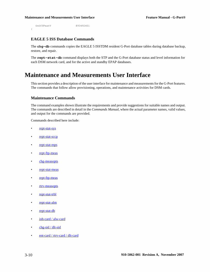
OnOffFeatV 893492401;
EAGLE 5 ISS Database Commands
The chg-db commands copies the EAGLE 5 ISSTDM resident G-Port database tables during database backup,restore, and repair.
The rept-stat-db command displays both the STP and the G-Port database status and level information foreach DSM network card, and for the active and standby EPAP databases.
Maintenance and Measurements User InterfaceThis section provides a description of the user interface for maintenance and measurements for the G-Port features.The commands that follow allow provisioning, operations, and maintenance activities for DSM cards.
Maintenance Commands
The command examples shown illustrate the requirements and provide suggestions for suitable names and output.The commands are described in detail in the Commands Manual, where the actual parameter names, valid values,and output for the commands are provided.
Commands described here include:
• rept-stat-sys
• rept-stat-sccp
• rept-stat-mps
• rept-ftp-meas
• chg-measopts
• rept-stat-meas
• rept-ftp-meas
• rtrv-measopts
• rept-stat-trbl
• rept-stat-alm
• rept-stat-db
• inh-card / alw-card
• chg-sid / dlt-sid
• ent-card / rtrv-card / dlt-card
Maintenance and Measurements User Interface Feature Manual - G-Port®
3-10 910-5062-001 Revision A, November 2007

• chg-gpl / act-gpl / rtrv-gpl / rept-stat-gpl / copy-gpl
• inh-alm / unhb-alm
• pass:cmd="help" , including ping, netstat, nslookup, arp, and help commands
rept-stat-sys
The rept-stat-sys command is used to determine the location of troubles in the system. The display showsthe number of these items that are in service (IS-NR) and how many are in another state (IS-ANR, OOS-MT,OOS-MT-DSBLD).
rept-stat-sccp
This command is used to display the status of the SCCP and VSCCP cards and the GTT (Global TitleTranslation), G-Flex (GSM Flexible Numbering), G-Port (GSM Mobile Number Portability), A-Port (ANSI-41Mobile Number Portability), Migration, INP (INAP-based Number Portability), and EIR (Equipment IdentityRegister) services executing on those cards. This command also displays any cards that are denied SCCP service.
Here are two sample commands and their outputs.
• rept-stat-sccp for a system that has the GTT, G-Flex, G-Port, and INP feaures enabled andactivated
Command entered at terminal #3.; tekelecstp 00-06-23 13:34:22 EST EAGLE 36.0.0-30.10.0 SCCP SUBSYSTEM REPORT IS-NR Active ----- GSM SUBSYSTEM REPORT IS-NR Active ----- SCCP Cards Configured= 4 Cards IS-NR= 2 Capacity Threshold = 100% CARD VERSION PST SST AST MSU USAGE CPU USAGE -------------------------------------------------------------------------------- 1212 101-001-000 IS-NR Active ALMINH 45% 30% 1301 101-001-000 IS-NR Active ------ 35% 20% 1305 ----------- OOS-MT Isolated ------ 0% 0% 2112 ----------- OOS-MT-DSBLD Manual ------ 0% 0% -------------------------------------------------------------------------------- SCCP Service Average MSU Capacity = 40% Average CPU Capacity = 25% AVERAGE CPU USAGE PER SERVICE: GTT = 15% GPORT = 5% GPORT = 10% INPMR = 2% INPQS = 3% TOTAL SERVICE STATISTICS: SERVICE SUCCESS ERRORS WARNINGS FORWARD TO GTT TOTAL GTT: 1995 5 - - 2000 GFLEX: 500 1 4 10 515 GPORT: 800 0 2 3 800 INPMR: 50 5 1 15 70 INPQS: 499 1 - - 500 Command Completed.;
• rept-stat-sccp:loc=1107 for a system that has the GTT, G-Flex, G-Port, and INP featuresenabled and activated
Command entered at terminal #4.; tekelecstp 00-06-23 13:34:22 EST EAGLE 36.0.0-33.10.0 CARD VERSION TYPE PST SST AST
Feature Manual - G-Port® Maintenance and Measurements User Interface
910-5062-001 Revision A, November 2007 3-11

1106 103-010-000 DSM IS-NR Active ----- ALARM STATUS = No Alarms. GTT: STATUS = ACT MSU USAGE = 10% GFLEX: STATUS = ACT MSU USAGE = 10% GPORT: STATUS = ACT MSU USAGE = 10% INPMR: STATUS = ACT MSU USAGE = 13% INPQS: STATUS = ACT MSU USAGE = 20% CPU USAGE = 15% CARD SERVICE STATISTICS: SERVICE SUCCESS ERRORS WARNINGS FORWARD TO GTT TOTAL GTT: 1995 5 - - 2000 GFLEX: 500 1 4 10 515 GPORT: 500 1 4 10 515 INPMR: 50 2 3 15 70 INPQS: 499 1 - - 500 Command Completed.;
rept-stat-mps
There are two variants of this new command.
• rept-stat-mps - produces a summary report showing the overall status of the G-Port provisioningsystem and a moderate level of information for each DSM card.
• rept-stat-mps:loc=xxxx - produces a more detailed report showing the G-Port status of a specificDSM card. Note that this version of the command displays the percent utilization of a particular DSMmemory.
Here are two sample commands and their outputs.
• rept-stat-mps
Command entered at terminal #4.; Integrat40 00-06-24 10:37:22 EST EAGLE 37.2-30.10.0 VERSION PST SST AST EPAP A 026-015-000 IS-NR Active ----- ALARM STATUS = No Alarms EPAP B 026-015-000 IS-NR Standby ----- ALARM STATUS = No Alarms CARD PST SST GSM STAT INP STAT 1106 P IS-NR Active ACT ACT 1201 IS-ANR Active SWDL SWDL 1205 OOS-MT-DSBLD Manual ------- ------- 1302 OOS-MT Fault ------- ------- 1310 IS-ANR Standby SWDL SWDL CARD 1106 ALARM STATUS = No Alarms CARD 1201 ALARM STATUS = No Alarms CARD 1205 ALARM STATUS = No Alarms CARD 1302 ALARM STATUS = ** 0013 Card is isolated from the system CARD 1310 ALARM STATUS = No Alarms Command Completed.
• rept-stat-mps:loc=1106 Command entered at terminal #4.; integrat40 99-09-24 10:37:22 EST EAGLE 37.2.0 CARD VERSION TYPE PST SST AST 1106 101-9-000 DSM IS-NR Active ----- DSM PORT A IS-NR Active -----
Maintenance and Measurements User Interface Feature Manual - G-Port®
3-12 910-5062-001 Revision A, November 2007

DSM PORT B IS-NR Active ----- GTT STATUS = ACT GSM STATUS = ACT ALARM STATUS = No Alarms. DSM MEMORY USAGE = xxx% Command Completed.;
rept-meas
This command includes G-Port measurements in the output sent to the EAGLE 5 ISS Terminal. Refer to theCommands Manual for details of this command.
chg-measopts
Used to enable or disable the automatic generation and FTP transfer of scheduled measurement reports to theFTP server. Refer to the Commands Manual for details of this command.
rept-stat-meas
Reports the status of the measurements subsystem including card location and state, Alarm level, and SubsystemState. Refer to the Commands Manual for details of this command.
rept-ftp-meas
Manually initiates generation and FTP transfer of a measurements report from the MCPM to the FTP server. Referto the Commands Manual for details of this command.
rtrv-measopts
Generates a user interface display showing the enabled/disabled status of all FTP scheduled reports. Refer to theCommands Manual for details of this command.
rept-stat-trbl
This command includes the G-Port subsystem and DSM/EPAPIPlink alarms. Refer to the Commands Manual fordetails of this command. Here is an example of the command and its output.
rept-stat-trbl
Command Accepted - Processing eagle10605 99-06-24 14:34:08 EST EAGLE 37.2.0 rept-stat-trbl Command entered at terminal #10.; eagle10605 99-06-24 14:34:08 EST EAGLE 37.2.0 Searching devices for alarms...; eagle10605 99-06-24 14:34:09 EST EAGLE 37.2.0 SEQN UAM AL DEVICE ELEMENT TROUBLE TEXT 0002.0143 * CARD 1113 OAM System release GPL(s) not approved 0011.0176 * SECULOG 1116 Stdby security log -- upload required 3540.0203 ** SLK 1201,A lsn1 REPT-LKF: lost data
Feature Manual - G-Port® Maintenance and Measurements User Interface
910-5062-001 Revision A, November 2007 3-13

3541.0203 ** SLK 1201,B lsn4 REPT-LKF: lost data 3542.0203 ** SLK 1202,A lsn2 REPT-LKF: lost data 3544.0202 ** SLK 1203,A lsn3 REPT-LKF: HWP - too many link interrupts 0021.0318 ** LSN lsn1 REPT-LKSTO: link set prohibited 0022.0318 ** LSN lsn2 REPT-LKSTO: link set prohibited 0023.0318 ** LSN lsn3 REPT-LKSTO: link set prohibited 0010.0318 ** LSN lsn4 REPT-LKSTO: link set prohibited 3537.0084 ** DSM A 1215 IP Connection Unavailable 3536.0084 ** EPAP B 7100 IP Connection Unavailable 0003.0313 *C DPC 010-010-003 DPC is prohibited 0004.0313 *C DPC 010-010-004 DPC is prohibited 0005.0313 *C DPC 010-010-005 DPC is prohibited 0028.0313 *C DPC 252-010-001 DPC is prohibited 0006.0313 *C DPC 252-010-003 DPC is prohibited 0008.0313 *C DPC 252-010-004 DPC is prohibited 0009.0313 *C DPC 252-011-* DPC is prohibited 0029.0308 *C SYSTEM Node isolated due to SLK failuresCommand Completed.;
rept-stat-alm
This command includes the alarm totals of the G-Port subsystem and DSM/EPAPIP links. Refer to the CommandsManual for details of this command. Here is an example of the command and its output.
rept-stat-alm
Command Accepted - Processing eagle10605 99-06-24 23:59:39 EST EAGLE 37.2.0 rept-stat-alm Command entered at terminal #10.; eagle10605 99-06-24 23:59:39 EST EAGLE 37.2.0 ALARM TRANSFER= RMC ALARM MODE CRIT= AUDIBLE MAJR= AUDIBLE MINR= AUDIBLE ALARM FRAME 1 CRIT= 9 MAJR= 12 MINR= 2 ALARM FRAME 2 CRIT= 0 MAJR= 0 MINR= 0 ALARM FRAME 3 CRIT= 0 MAJR= 0 MINR= 0 ALARM FRAME 4 CRIT= 0 MAJR= 0 MINR= 0 ALARM FRAME 5 CRIT= 0 MAJR= 0 MINR= 0 ALARM FRAME 6 CRIT= 0 MAJR= 0 MINR= 0 ALARM FRAME GPF CRIT= 1 MAJR= 2 MINR= 1 PERM. INH. ALARMS CRIT= 0 MAJR= 0 MINR= 0 TEMP. INH. ALARMS CRIT= 0 MAJR= 0 MINR= 0 ACTIVE ALARMS CRIT= 10 MAJR= 14 MINR= 3 TOTAL ALARMS CRIT= 10 MAJR= 14 MINR= 3 Command Completed.;
rept-stat-db
This command displays both EAGLE 5 ISS and G-Port database status and level information for each DSM networkcard, and for the active and standby EPAP databases. It reports database exception status such as corrupted, incoherent, or inconsistent, as well as providing the birthdates and levels. For details about this command, referto the Commands Manual.
inh-card / alw-card
The inh-card command is used to change the state of the card from in-service normal (IS-NR) to Out-of-ServiceMaintenance-Disabled (OOS-MT-DSBLD). A craftsperson then can test the DCM/LIM/ACM/ASM/DSM/GPSM-II/MIM card or physically remove it from the shelf.
Maintenance and Measurements User Interface Feature Manual - G-Port®
3-14 910-5062-001 Revision A, November 2007

The alw-card command is used to change the card from OOS-MT-DSBLD (out-of-service maintenance-disabled) to IS-NR (in-service normal) if the loading is successful.
Refer to the Commands Manual for details of these commands.
chg-sid / dlt-sid
These commands are used to change and report on the self-identification of the EAGLE 5 ISS. The self-identification identifies the EAGLE 5 ISS to other signaling points in the network. This command includes aCPC type for G-Port.
The CPC parameter is used to support incoming messages routed via Intermediate GTT (rt-gt) to the EAGLE 5ISS (with DPC = CPC) for G-Port. Refer to the Commands Manual for details of this command.
ent-card / rtrv-card / dlt-card
The ent-card command is used to add a card to the database. The card type and application specifies the functionassigned to the card.
The rtrv-card command is used to display the information about a card. This command displays thecard type,the application the card is running, the linkset name, the signaling link code, and the ports.
The dlt-card command is used to remove a card entry from the system database.
Refer to the Commands Manual for details on using these commands.
chg-gpl / act-gpl / rtrv-gpl / rept-stat-gpl / copy-gpl
The chg-gpl command is used to copy a generic program load from the source disk to the destination disk (bothactive and standby disks). The new GPL becomes the trial version on each of the destination disks. This commandalso copies the system release table to the fixed disks.
The act-gpl command is used to change the status of the trial GPL from “trial” to “approved.” The status ofthe previously approved GPL is changed to “trial.”
The rtrv-gpl command is used to show the version numbers of the GPLs stored on each fixed disk (TDM) orremovable cartridge (MDAL, if available) and the system release table stored on each fixed disk.
The rept-stat-gpl command is used to display the version of GPLs currently running for an application, plusthe approved and trial versions of the GPL that will run if the card is restarted.
The copy-gpl command is used to copy all approved GPLs from one drive to another. The GPLs can be copiedonly from the fixed disk on the active TDM to the removable cartridge, or from the removable cartridge to thefixed disk on the standby TDM.
Refer to the Commands Manual for details of these commands.
Here are samples of the reports produced by these commands.
• chg-gpl:appl=vsccp:ver=101-3-0 Command entered at terminal #3.; tekelecstp 99-10-24 06:54:39 EST EAGLE 37.2.0 VSCCP upload to 1114 completed
Feature Manual - G-Port® Maintenance and Measurements User Interface
910-5062-001 Revision A, November 2007 3-15
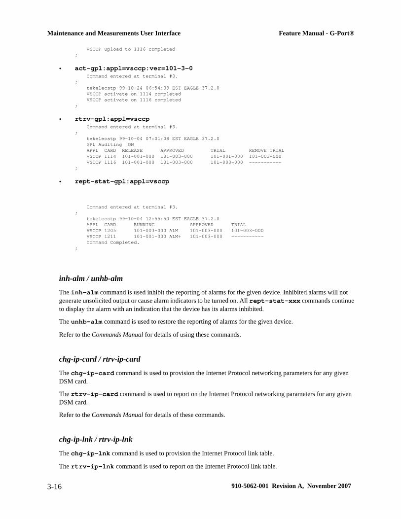
VSCCP upload to 1116 completed;
• act-gpl:appl=vsccp:ver=101-3-0 Command entered at terminal #3.; tekelecstp 99-10-24 06:54:39 EST EAGLE 37.2.0 VSCCP activate on 1114 completed VSCCP activate on 1116 completed;
• rtrv-gpl:appl=vsccp Command entered at terminal #3.; tekelecstp 99-10-04 07:01:08 EST EAGLE 37.2.0 GPL Auditing ON APPL CARD RELEASE APPROVED TRIAL REMOVE TRIAL VSCCP 1114 101-001-000 101-003-000 101-001-000 101-003-000 VSCCP 1116 101-001-000 101-003-000 101-003-000 -----------;
• rept-stat-gpl:appl=vsccp
Command entered at terminal #3.; tekelecstp 99-10-04 12:55:50 EST EAGLE 37.2.0 APPL CARD RUNNING APPROVED TRIAL VSCCP 1205 101-003-000 ALM 101-003-000 101-003-000 VSCCP 1211 101-001-000 ALM+ 101-003-000 ----------- Command Completed.;
inh-alm / unhb-alm
The inh-alm command is used inhibit the reporting of alarms for the given device. Inhibited alarms will notgenerate unsolicited output or cause alarm indicators to be turned on. All rept-stat-xxx commands continueto display the alarm with an indication that the device has its alarms inhibited.
The unhb-alm command is used to restore the reporting of alarms for the given device.
Refer to the Commands Manual for details of using these commands.
chg-ip-card / rtrv-ip-card
The chg-ip-card command is used to provision the Internet Protocol networking parameters for any givenDSM card.
The rtrv-ip-card command is used to report on the Internet Protocol networking parameters for any givenDSM card.
Refer to the Commands Manual for details of these commands.
chg-ip-lnk / rtrv-ip-lnk
The chg-ip-lnk command is used to provision the Internet Protocol link table.
The rtrv-ip-lnk command is used to report on the Internet Protocol link table.
Maintenance and Measurements User Interface Feature Manual - G-Port®
3-16 910-5062-001 Revision A, November 2007

Refer to the Commands Manual for details of these commands.
ent-ip-host / dlt-ip-host / rtrv-ip-host
These commands are used to provision, remove, and report on the entries in the Internet Protocol host table. The IP host table defines local and remote host names for IP addresses.
Refer to the Commands Manual for details of these commands.
pass
The pass command allows remote execution of a selected command by the targeted card. (These commandsrecognize the DSM boards.) Selected commands are allowed as follows.
• pass:cmd="ping"
• pass:cmd="netstat"
• pass:cmd="nslookup"
• pass:cmd="arp"
• pass:cmd="help"
For this feature, the loc parameter must be a VSCCP card location. For other details of the pass command, referto Commands Manual.
pass: cmd="Ping"
The 'ping' pass command supports troubleshooting of the private EPAP/DSMIP network. The followingexample demonstrates typical usage.
eagle10506 99-08-11 08:43:45 EST EAGLE 37.0.0 pass:loc=1215:cmd="ping -h" Command entered at terminal #2.; eagle10506 99-08-11 08:43:45 EST EAGLE 37.0.0 PASS: Command sent to card; eagle10506 99-08-11 08:43:45 EST EAGLE 37.0.0 Usage: ping <hostname | ipaddr> [-h] [-i size] [-n count] Options: -h Displays this message -i count Number of pings to send. Range=1..5. Default=3. -n size Sets size of ICMP echo packet. Range=12..2048. Default=64. hostname Name of machine to ping ipaddr IP Address of machine to ping (d.d.d.d);
pass:cmd="netstat"
The 'netstat'pass command supports troubleshooting of network interface and routing configurationproblems within the private EPAP/DSMIP network.
The following examples demonstrate typical usage.
Feature Manual - G-Port® Maintenance and Measurements User Interface
910-5062-001 Revision A, November 2007 3-17
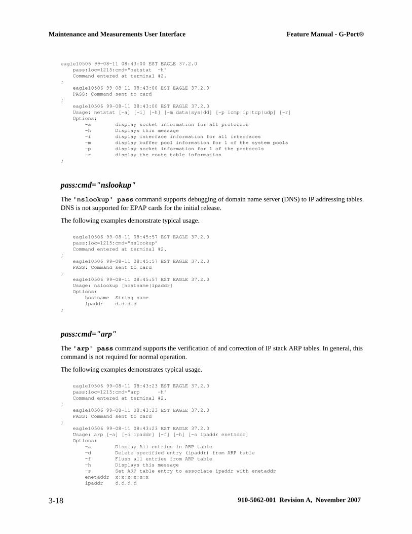
eagle10506 99-08-11 08:43:00 EST EAGLE 37.2.0 pass:loc=1215:cmd="netstat -h" Command entered at terminal #2.; eagle10506 99-08-11 08:43:00 EST EAGLE 37.2.0 PASS: Command sent to card; eagle10506 99-08-11 08:43:00 EST EAGLE 37.2.0 Usage: netstat [-a] [-i] [-h] [-m data|sys|dd] [-p icmp|ip|tcp|udp] [-r] Options: -a display socket information for all protocols -h Displays this message -i display interface information for all interfaces -m display buffer pool information for 1 of the system pools -p display socket information for 1 of the protocols -r display the route table information;
pass:cmd="nslookup"
The 'nslookup' pass command supports debugging of domain name server (DNS) to IP addressing tables.DNS is not supported for EPAP cards for the initial release.
The following examples demonstrate typical usage.
eagle10506 99-08-11 08:45:57 EST EAGLE 37.2.0 pass:loc=1215:cmd="nslookup" Command entered at terminal #2.; eagle10506 99-08-11 08:45:57 EST EAGLE 37.2.0 PASS: Command sent to card; eagle10506 99-08-11 08:45:57 EST EAGLE 37.2.0 Usage: nslookup [hostname|ipaddr] Options: hostname String name ipaddr d.d.d.d;
pass:cmd="arp"
The 'arp' pass command supports the verification of and correction of IP stack ARP tables. In general, thiscommand is not required for normal operation.
The following examples demonstrates typical usage.
eagle10506 99-08-11 08:43:23 EST EAGLE 37.2.0 pass:loc=1215:cmd="arp -h" Command entered at terminal #2.; eagle10506 99-08-11 08:43:23 EST EAGLE 37.2.0 PASS: Command sent to card; eagle10506 99-08-11 08:43:23 EST EAGLE 37.2.0 Usage: arp [-a] [-d ipaddr] [-f] [-h] [-s ipaddr enetaddr] Options: -a Display All entries in ARP table -d Delete specified entry (ipaddr) from ARP table -f Flush all entries from ARP table -h Displays this message -s Set ARP table entry to associate ipaddr with enetaddr enetaddr x:x:x:x:x:x ipaddr d.d.d.d
Maintenance and Measurements User Interface Feature Manual - G-Port®
3-18 910-5062-001 Revision A, November 2007

; eagle10506 99-08-11 08:43:25 EST EAGLE 37.2.0 ARP command complete;
pass:cmd="help"
The 'help' pass command provides a list of supported pass commands for the target location.
The following examples demonstrates typical usage.
eagle10506 99-08-11 08:42:18 EST EAGLE 37.2.0 pass:loc=1215:cmd="help" Command entered at terminal #2.; eagle10506 99-08-11 08:42:18 EST EAGLE 37.2.0 PASS: Command sent to card; eagle10506 99-08-11 08:42:18 EST EAGLE 37.2.0 List of commands supported is: nslookup netstat arp ping help END of LIST;
Feature Manual - G-Port® Maintenance and Measurements User Interface
910-5062-001 Revision A, November 2007 3-19

Maintenance and Measurements User Interface Feature Manual - G-Port®
3-20 910-5062-001 Revision A, November 2007

4
G-Port Feature Activation
Introduction..........................................................................................................................................................4-1Prerequisites..........................................................................................................................................................4-2Feature Activation Overview................................................................................................................................4-3Feature Activation Procedure...............................................................................................................................4-6PPSMS Provisioning and Activation..................................................................................................................4-35ISUP NP with EPAP Provisioning and Activation............................................................................................4-36The 1100 TPS/DMS for ITU NP Feature...........................................................................................................4-38
Activating the 1100 TPS/DSM for ITU NP Feature ..................................................................................4-38Activating the E5-SM4G Throughput Capacity Feature....................................................................................4-43
IntroductionCAUTION: Once a feature has been enabled with the enable-ctrl-feat command, itcannot be turned off. Since features may overwrite other features or create changes in thedatabase, assure that you have a license and full technical support from Tekelec before turningon this or any feature.The G-Port feature requires a DSM card running the VSCCP application. Systems withTSM cards running the SCCP application need to be upgraded to DSM cards prior to turningon the G-Port feature.
Refer to the Dimensioning Guide for EPAP Advanced DB Features Technical Reference forimportant information on the dimensioning rules and the DSM database capacityrequirements.
Procedures described in the remainder of this section apply only to the G-Port feature and canonly be performed if the G-Port feature is turned on.
This chapter identifies prerequisites for the G-Port feature activation procedure, an overview of the activationsteps, and a matching number of detailed step descriptions to turn on the G-Port feature. The G-Port featureactivation is performed at the EAGLE 5 ISS.
The G-Port features optimizes the use of subscriber numbers and number ranges in a GSM Mobile Network byproviding a logical link between any Mobile Station international ISDN (MSISDN) number and any InternationalMobile Station Identifier (IMSI). This feature allows subscribers to be moved easily from one Home LocationRegister (HLR) to another. The G-Port feature applies to ITU-I (international) and ITU-N (national) networks.
910-5062-001 Revision A, November 2007 4-1
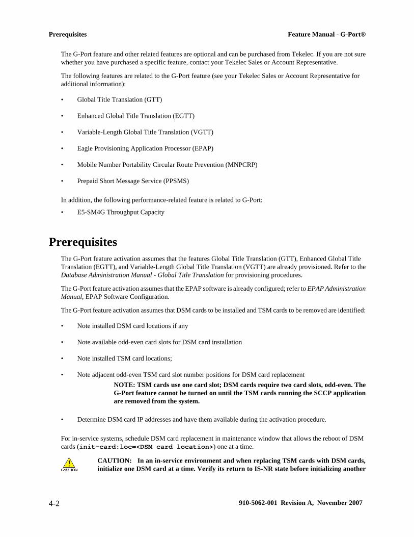
The G-Port feature and other related features are optional and can be purchased from Tekelec. If you are not surewhether you have purchased a specific feature, contact your Tekelec Sales or Account Representative.
The following features are related to the G-Port feature (see your Tekelec Sales or Account Representative foradditional information):
• Global Title Translation (GTT)
• Enhanced Global Title Translation (EGTT)
• Variable-Length Global Title Translation (VGTT)
• Eagle Provisioning Application Processor (EPAP)
• Mobile Number Portability Circular Route Prevention (MNPCRP)
• Prepaid Short Message Service (PPSMS)
In addition, the following performance-related feature is related to G-Port:
• E5-SM4G Throughput Capacity
PrerequisitesThe G-Port feature activation assumes that the features Global Title Translation (GTT), Enhanced Global TitleTranslation (EGTT), and Variable-Length Global Title Translation (VGTT) are already provisioned. Refer to theDatabase Administration Manual - Global Title Translation for provisioning procedures.
The G-Port feature activation assumes that the EPAP software is already configured; refer to EPAP AdministrationManual, EPAP Software Configuration.
The G-Port feature activation assumes that DSM cards to be installed and TSM cards to be removed are identified:
• Note installed DSM card locations if any
• Note available odd-even card slots for DSM card installation
• Note installed TSM card locations;
• Note adjacent odd-even TSM card slot number positions for DSM card replacementNOTE: TSM cards use one card slot; DSM cards require two card slots, odd-even. TheG-Port feature cannot be turned on until the TSM cards running the SCCP applicationare removed from the system.
• Determine DSM card IP addresses and have them available during the activation procedure.
For in-service systems, schedule DSM card replacement in maintenance window that allows the reboot of DSMcards (init-card:loc=<DSM card location>) one at a time.
CAUTION: In an in-service environment and when replacing TSM cards with DSM cards,initialize one DSM card at a time. Verify its return to IS-NR state before initializing another
Prerequisites Feature Manual - G-Port®
4-2 910-5062-001 Revision A, November 2007
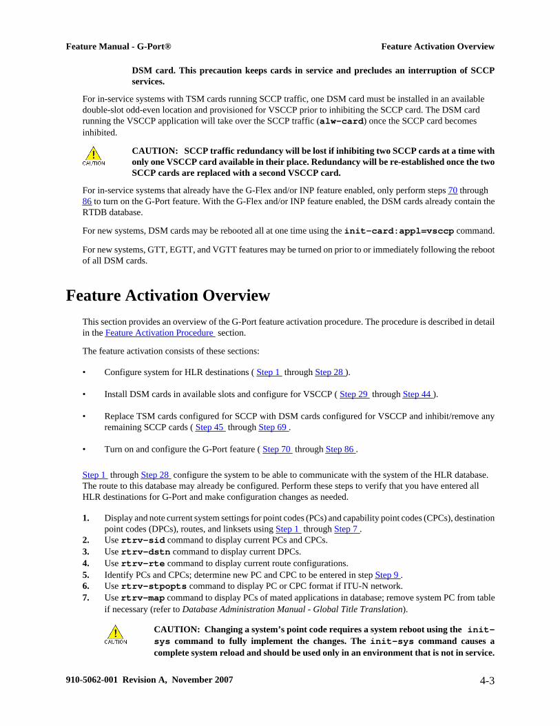
DSM card. This precaution keeps cards in service and precludes an interruption of SCCPservices.
For in-service systems with TSM cards running SCCP traffic, one DSM card must be installed in an availabledouble-slot odd-even location and provisioned for VSCCP prior to inhibiting the SCCP card. The DSM cardrunning the VSCCP application will take over the SCCP traffic (alw-card) once the SCCP card becomesinhibited.
CAUTION: SCCP traffic redundancy will be lost if inhibiting two SCCP cards at a time withonly one VSCCP card available in their place. Redundancy will be re-established once the twoSCCP cards are replaced with a second VSCCP card.
For in-service systems that already have the G-Flex and/or INP feature enabled, only perform steps 70 through86 to turn on the G-Port feature. With the G-Flex and/or INP feature enabled, the DSM cards already contain theRTDB database.
For new systems, DSM cards may be rebooted all at one time using the init-card:appl=vsccp command.
For new systems, GTT, EGTT, and VGTT features may be turned on prior to or immediately following the rebootof all DSM cards.
Feature Activation OverviewThis section provides an overview of the G-Port feature activation procedure. The procedure is described in detailin the Feature Activation Procedure section.
The feature activation consists of these sections:
• Configure system for HLR destinations ( Step 1 through Step 28 ).
• Install DSM cards in available slots and configure for VSCCP ( Step 29 through Step 44 ).
• Replace TSM cards configured for SCCP with DSM cards configured for VSCCP and inhibit/remove anyremaining SCCP cards ( Step 45 through Step 69 .
• Turn on and configure the G-Port feature ( Step 70 through Step 86 .
Step 1 through Step 28 configure the system to be able to communicate with the system of the HLR database.The route to this database may already be configured. Perform these steps to verify that you have entered allHLR destinations for G-Port and make configuration changes as needed.
1. Display and note current system settings for point codes (PCs) and capability point codes (CPCs), destinationpoint codes (DPCs), routes, and linksets using Step 1 through Step 7 .
2. Use rtrv-sid command to display current PCs and CPCs.3. Use rtrv-dstn command to display current DPCs.4. Use rtrv-rte command to display current route configurations.5. Identify PCs and CPCs; determine new PC and CPC to be entered in step Step 9 .6. Use rtrv-stpopts command to display PC or CPC format if ITU-N network.7. Use rtrv-map command to display PCs of mated applications in database; remove system PC from table
if necessary (refer to Database Administration Manual - Global Title Translation).
CAUTION: Changing a system’s point code requires a system reboot using the init-sys command to fully implement the changes. The init-sys command causes acomplete system reload and should be used only in an environment that is not in service.
Feature Manual - G-Port® Feature Activation Overview
910-5062-001 Revision A, November 2007 4-3

Using this command ensures the updated self identification information is loaded ontoall cards, but does interrupt service.
8. Change PC, CPC, DPC, route, linkset, and LIM card configurations for the HLR database using Step 9through Step 28 .
9. Use chg-sid command to configure PC and CPC by network type.10. Use init-sys command to initialize system if changes were made in step Step 9 to any pca/pci/
pcn parameter.
CAUTION: The init-sys command causes a complete system reload and should beused only in an environment that is not in service. Using this command ensures theupdated self identification information is loaded onto all cards, but does interruptservice.When the init-sys command executes, the system does not retain the manuallyinitiated state (for example, OOS-MT-DSBLD) for the signaling link, card, or terminal.After the command executes, the system attempts to bring all provisioned links, cards,and terminals on line, including those that were previously out of service. You will needto manually put each device back into its previous state after the system is back on line.Print or electronically capture the output of the rept-stat-slk, rept-stat-card, and rept-stat-trm commands for reference prior to issuing the init-sys command. To restore a device to its previous state, issue the appropriate inhibit/deactivate command listed in the EAGLE 5 ISS Commands Manual in the RelatedCommands section for each of the above rept-stat commands.
11. Use rtrv-sid command to display new PC and CPC.12. Use ent-dstn command to enter DPC for HLR destinations.13. Use rtrv-dstn command to display new HLRDPC.14. Use ent-ls command to enter linkset and assign DPC for HLR destinations.15. Use rtrv-ls command to display new linkset and assigned DPC for HLR destinations.16. Use ent-card command to enter LIM card(s) into database.17. Use rtrv-card command to display new LIM card(s) in database.18. Use ent-slk command to assign signaling link(s) to LIM card(s).19. Use rtrv-slk command to display new signaling link(s) assigned to LIM card(s).20. Use ent-rte command to assign route to new DPC.21. Use rtrv-rte command to display route assigned to new DPC.22. Use ent-map command to enter mated application into database.23. Use rtrv-map command to display new mated application in database.24. Use alw-card command to allow LIM card(s).25. Use rept-stat-card command to display status of new LIM card(s) in database.26. Use act-slk command to activate new signaling link(s) for LIM card(s).27. Use rept-stat-slk command to display IS-NR status of signaling link(s).28. Use rtrv-card command to confirm the new LIM card(s) and identify VSCCP cards (DSM cards running
VSCCP application) and SCCP cards (TSM cards running SCCP application).
CAUTION: When adding DSM cards in an in-service environment, you must take carenot to interrupt traffic. Before replacing SCCP cards with DSMs, first install a VSCCPcard in an available odd-even double-slot prior to removing SCCP cards to makeadditional room for other DSM cards.
29. Install and configure DSM card(s) in available odd-even slots as needed using Step 30 through Step 44 .30. Install DSM card(s) in available odd-even slots and verify green IMT bus LEDs.31. Use ent-card command to enter DSM card(s) as VSCCP card(s) into database.
Feature Activation Overview Feature Manual - G-Port®
4-4 910-5062-001 Revision A, November 2007

32. Use rtrv-card command to display new VSCCP card(s) in database.33. Use rtrv-ip-lnk command to display current link parameters associated with the VSCCP card.34. Use chg-ip-lnk command to set the IP address port and speed associated with the VSCCP card.35. Use rtrv-ip-lnk command to display changed link parameters. Use rtrv-ip-host command to
display current IP host information in database.36. Use ent-ip-host command to add host name and IP address for each VSCCP link.37. Use rtrv-ip-host command to display changed IP host information.38. Use chg-ip-card command to set local domain and IP router address if necessary.39. Use rtrv-ip-card command to display changed VSCCP card information.40. Use alw-card command to boot DSM card in TSM emulation mode.41. Use rept-stat-card command to display IS-NR status of VSCCP card.42. Use pass command to test presence of EPAP hosts on network.43. Repeat Step 30 through Step 43 to add all DSM cards (N+1) to be installed in available slots.
Go to the next step to start replacing TSM cards.44. Replace TSM card(s) with DSM cards if applicable, and add DSM card(s) to database using Step 46 through
Step 68 .45. Use rtrv-card command to display TSM cards running the SCCP application (SCCP cards) in
database.46. Use rept-stat-card command to display SCCP cards in IS-NR status.47. Use inh-card command to inhibit SCCP card(s).48. Use rept-stat-card command to display OOS-MT-DSBLD status of SCCP card(s).49. Use dlt-card command to delete SCCP card(s) from database.50. Use rtrv-card command to verify removal of SCCP cards from database.51. Remove first TSM card from shelf.52. Remove second TSM card from shelf.53. Install DSM card in shelf and verify green IMT bus LEDs.54. Use ent-card command to enter DSM card as VSCCP card into database.55. Use rtrv-card command to display new VSCCP card in database.56. Use rtrv-ip-lnk command to display current parameters associated with VSCCP card.57. Use chg-ip-lnk command to set the IP address port and speed associated with VSCCP card.58. Use rtrv-ip-lnk command to display changed link parameters associated with the VSSCP card.59. Use rtrv-ip-host command to display IP host information in database.60. Use ent-ip-host command to add host name and IP address for VSCCP link.61. Use rtrv-ip-host command to display changed IP host information in database.62. Use chg-ip-card command to set local domain and IP router address if necessary.63. Use rtrv-ip-card command to display changed VSCCP card information.64. Use alw-card command to boot DSM card in TSM emulation mode.65. Use rept-stat-card command to display IS-NR status of VSCCP card.66. Use pass command to test presence of EPAP hosts on network.67. Repeat Step 46 through Step 67 to replace all adjacent TSM cards identified in the prerequisites and to be
replaced with DSM cards.68. Repeat Step 48 through Step 52 to inhibit any remaining TSM cards running the SCCP application and
remove them from database and shelf.
NOTE : The G-Port feature cannot be turned on until TSM cards running the SCCPapplication are removed from the system.
CAUTION: Contact the Tekelec Customer Care Center at this point for assistance incompleting this G-Port activation procedure (see Customer Care Center ). Do not proceedwithout consulting with the Tekelec Customer Care Center.
69. Turn on G-Port feature and configure it using Step 70 through Step 84 .
Feature Manual - G-Port® Feature Activation Overview
910-5062-001 Revision A, November 2007 4-5

70. Use enable-ctrl-feat command to enable the G-Port feature.71. Use chg-ctrl-feat command to turn on the G-Port feature.
NOTE: Step 74 through Step 81 describe the commands that administer the G-Portprotocol flow to support:
• G-PortSRIACK (Ported-out MSISDNs)
• G-PortSRIACK (Foreign MSISDNs not known to be ported)
• G-Port Message Relay (Ported-in, non-ported MSISDNs)
72. Use chg-stpopts command to enter default country code (CC) and default network destination code(NDC) if handling non-international numbers.
73. Use rtrv-stpopts command to verify changes of CC and NDC.74. Use chg-gsmopts command to change GSM options.75. Use rtrv-gsmopts command to verify changes to GSM options.76. Use the ent-homern command to enter any Home RNs that are prefixed to DNs for incoming INPMR
messages.77. Use rtrv-homern command to verify routing number prefixes.78. Use ent-srvsel command to enter G-Port service selectors.79. Use rtrv-srvsel command to verify changes to G-Port service selectors.
CAUTION: When the environment is in-service and TSM cards are being replaced withDSM cards, initialize one DSM card at a time. Verify its return to IS-NR state beforeinitializing another card. This precaution keeps cards in service and precludes aninterruption of SCCP services.
80. Use init-card:loc=<DSM card> command to load RTDB, OAM, GPL, and GTT data to VSCCPcard.
81. Use rept-stat-card command to display IS-NR status of VSCCP card.82. Repeat Step 82 and Step 83 to reboot each DSM card.
NOTE: Once the G-Port feature is turned on, always boot the DSM cards with the init-card:loc=<DSM card location> command.
83. Use chg-sccp-serv:serv=gport:state=online to set the G-Port service to online.84. Confirm success of activation procedure with rept-stat-sccp, rept-stat-mps, and rept-stat-
db:display=all commands.
EPAP can now administer G-Port entity objects and G-Port subscribers. For the details about performing theseactions, refer to the EPAP Administration Manual. The detailed G-Port activation procedure is described next.
Feature Activation Procedure1. Before changing a true point code (PC) and adding a capability point code (CPC) for the G-Port feature,
display the current values of the self-identification configuration (shown in step Step 2 ), the destinationpoint codes (DPCs) (shown in step Step 3 ), and the routes and linksets assigned to the DPCs (shown in stepStep 4 ).The G-Port feature applies to ITU-I (international) and ITU-N (national) networks.
2. Display the current self identification of the system (PC and CPC) using the rtrv-sid command.
A sample output from this command follows:
rlghncxa03w 01-10-07 00:57:31 GMT EAGLE 37.0.0
Feature Activation Procedure Feature Manual - G-Port®
4-6 910-5062-001 Revision A, November 2007

PCA PCI PCN CLLI PCTYPE------------- 1-100-1 11111 rlghncxa03w OTHER
CPCA-------------
CPCI1-101-1 1-101-2 1-101-3 1-101-4
CPCN11121 11122 11123 11124
If the ITUDUPPC (ITU national duplicate point code) feature is on, the ITU national point code also containsa group code. The group code is a two-character field from aa to zz that is entered as the last subfield of anITU national point code, nnnnn-gc (for example, 2112-aa).
3. Display the current destination point codes in the destination point code table (dpci/dpcn) using the rtrv-dstn command.
A sample output from this command follows:
rlghncxa03w 01-10-10 11:43:04 GMT EAGLE 37.0.0DPCA CLLI BEI ELEI ALIASI ALIASN DOMAIN---------- ---------- --- --- ------- ------- ---
DPCI CLLI BEI ELEI ALIASA ALIASN DOMAIN2-100-1 rlghncxa03w no --- 222-210-000 12001 SS7
DPCN CLLI BEI ELEI ALIASA ALIASI DOMAIN21111 rlghncxa03w no --- 222-200-200 2-121-1 SS7
DESTINATION ENTRIES ALLOCATED: 2000 FULL DPC(s): 2 NETWORK DPC(s): 0 CLUSTER DPC(s): 0 TOTAL DPC(s): 2 CAPACITY (% FULL): 1%X-LIST ENTRIES ALLOCATED: 500
4. Display the current route configuration using the rtrv-rte command.
A sample output from this command follows:
rlghncxa03w 01-10-07 11:43:04 GMT EAGLE 37.0.0DPCA ALIASI ALIASN CLLI LSN RC APCA----------- ------- ------- ----- -------- -- -----------
DPCI ALIASN ALIASA CLLI LSN RC APCI2-100-1 121111 -------- idp1 ls100001 10 1-234-5 ls100002 10 1-234-6 ls100003 20 1-234-7 ls100004 30 1-234-1 ls100005 40 1-234-2 ls100006 50 1-234-3
DPCN ALIASA ALIASI CLLI LSN RC APCN21111 -------- 0-001-1 ndp1 ls200001 10 11111 ls200002 10 11112 ls200003 20 11113 ls200004 30 11114 ls200005 40 11115 ls200006 50 11116
5. If the system’s point code (pci/pcn) or capability point code (cpci/cpcn) to be configured in thisprocedure is shown in steps Step 2 , Step 3 , or Step 4 , choose another point code to configure with thisprocedure (go to step Step 9 ).
6. Use command to display PC or CPC format, if configuring the system point code or capability point code(pcn or cpcn) of an ITU-N Network.
Feature Manual - G-Port® Feature Activation Procedure
910-5062-001 Revision A, November 2007 4-7

• If configuring the system point code or capability point code (pcn or cpcn) of an ITU-N network,view the current value of the ITU-N point code format.
• Otherwise continue with step Step 7 .
Enter the rtrv-stpopts command and specify the ITU-N point code format option npcfmti. Thenpcfmti option identifies how the ITU-N point code is entered into the database and how it is displayedin any outputs. The value is shown in the NPCFMTI field.
A sample output from this command follows:
rlghncxa03w 01-10-17 16:02:05 GMT EAGLE 37.0.0STP OPTIONS-----------------------MTPT31CTL 1MTPLTI yesMTPLTCTDPCQ 3MTPLTST 10000MTPXLQ 500MTPXLET 0100MTPXLOT 90%MTPDPCQ 1750TFATFRPR 1000MTPRSI yesMTPRSIT 5000MTPLPRST yesMTPT10ALT 30000SLSCNV perlsUIMRD yesCRITALMINH noDISPACTALMS noNPCFMTI 4-4-4-2DEFCC 49DEFNDC 177DSMAUD on
Optional: To change the format of the ITU-N point code, go to section “ITU National Point Code Formats”in the EAGLE 5 ISS Database Administration Manual - SS7. Then continue with step Step 7 .
7. Display the mated applications in the database using the rtrv-map command.
Sample outputs for this command follow:
rlghncxa03w 01-10-07 11:43:04 GMT EAGLE 37.0.0PCN SSN RC MPCN MSSN MATERC SRM MRC GRP NAME11111 5 10 12347 5 20
rlghncxa03w 01-10-07 11:43:04 GMT EAGLE 37.0.0PCI SSN RC MPCI MSSN MATERC SRM MRC GRP NAME2-100-1 5 20 3-200-1 250 99 --- --- abcdefgh
a. If the system’s point code is shown in the rtrv-map command output (in the PCA, PCI, PCN,MPCA, MPCI, or MPCN fields), remove the system’s point code from the mated application table. Referto procedure “Removing a Mated Application” in the EAGLE 5 ISS Database Administration Manual- Features.
b. If the system’s point code or capability point code is a destination point code of a route, select a pointcode that is not the destination point code of a route (see output of the rtrv-rte command in stepStep 4 ) and not in the destination point code table (see output of the rtrv-dstn command in stepStep 3 ).
8. Change PC, CPC, DPC, route, linkset, and LIM card configurations for the HLR database using steps Step9 through Step 28 .
Feature Activation Procedure Feature Manual - G-Port®
4-8 910-5062-001 Revision A, November 2007

CAUTION: Changing a system’s point code requires a system reboot using the init-sys command to fully implement the changes. The init-sys command causes acomplete system reload and should be used only in an environment that is not in service.Using this command ensures the updated self identification information is loaded ontoall cards but does interrupt service.
9. Configure the system’s point code (pci/pcn) and capability point code (cpci/cpcn) by network typeusing the chg-sid command.
For example, enter one of these commands:
chg-sid:pci=1-100-2:cpci=1-102-1chg-sid:pcn=11112:cpcn=11125
where:pci/pcn:
The point code used to uniquely identify the system.cpci/cpcn:
The point code used by the SS7 protocol to identify a group of functionally related EAGLE 5 ISSs in thesignaling network to which the EAGLE 5 ISS belongs.
After successful completion of this command, the system returns the following output:
rlghncxa03w 01-10-07 00:57:31 GMT EAGLE 37.0.0CHG-SID: MASP A - COMPLTD
When any of the pci/pcn parameters have changed, the system needs to be reinitialized. The followingcaution message is displayed:
CAUTION: SYSTEM SITE ID HAS BEEN CHANGED, MANUAL RE-INITIALIZATION IS NEEDED
10. Reinitialize the system by entering the init-sys command if changes were made to any pca/pci/pcn parameter in step Step 9 .
CAUTION: The init-sys command causes a complete system reload and should beused only in an environment that is not in service. Using this command ensures theupdated self identification information is loaded onto all cards, but does interruptservice.When the init-sys command executes, the system does not retain the manuallyinitiated state (for example, OOS-MT-DSBLD) for the signaling link, card, or terminal.After the command executes, the system attempts to bring all provisioned links, cards,and terminals on line, including those that were previously out of service. You will needto manually put each device back into its previous state after the system is back on line.Print or electronically capture the output of the rept-stat-slk, rept-stat-card, and rept-stat-trm commands for reference prior to issuing the init-syscommand. To restore a device to its previous state, issue the appropriate inhibit/deactivate command listed in the EAGLE 5 ISS Commands Manual in the RelatedCommands section for each of the above rept-stat commands.
NOTE: The init-sys command must be entered twice within 30 seconds for the systemto re-initialize. If the init-sys command is not executed twice within 30 seconds, theattempt to re-initialize the system is aborted.
Feature Manual - G-Port® Feature Activation Procedure
910-5062-001 Revision A, November 2007 4-9

When the init-sys command is first entered, this message should appear.
rlghncxa03w 01-10-07 00:57:31 GMT EAGLE 37.0.0CAUTION: This command causes a complete system reload, andwill result in traffic loss.Re-enter command within 30 seconds to confirm.
When the init-sys command is re-entered within the 30 second time limit, this message should appear.
rlghncxa03w 01-10-07 00:57:31 GMT EAGLE 37.0.0Init System command issued at terminal #3
From the time that the init-sys command is accepted, approximately two minutes must elapse beforeperforming step Step 11 (logging into the system). If the terminal is in the VT-100/VT-320 mode, theterminal display will be refreshed with non-zero alarm counts. During this two-minute interval, anintermediate screen refresh occurs, which is caused by the MASP’s role change from active to standby andfrom standby to active. This screen refresh is typically a partial refresh and the alarm indicators are set tozero. If you are logged into the system in the KSR mode, the only response you will receive of being ableto log into the system is the message ‘UAM 0009, MASP became active’. UAM 0009 could be issued twicedue to a possible transient MASP role change (switching from active to standby). Following the executionof the init-sys command, the MASP that was active before the init-sys command was entered willbe the active MASP again when the system has finished reinitializing.
11. Verify the SID changes using the rtrv-sid command.
A sample output from this command follows:
durhncxa03w 01-10-07 00:57:31 GMT EAGLE 37.0.0PCA PCI PCN CLLI PCTYPE------------- 1-100-1 11111 rlghncxa03w OTHER
CPCA-------------
CPCI1-101-1 1-101-2 1-101-3 1-101-41-102-1
CPCN11121 11122 11123 1112411125
12. Enter a destination point code for the HLR location in the Destination Point Code table by network typeusing the ent-dstn command.
For example, enter one of these commands:
ent-dstn:dpci=2-100-2ent-dstn:dpcn=21112where:
:dpci/dpcnThe destination point code being added to the database
The system returns this message:
rlghncxa03w 01-10-17 15:35:05 GMT EAGLE 37.0.0
Feature Activation Procedure Feature Manual - G-Port®
4-10 910-5062-001 Revision A, November 2007
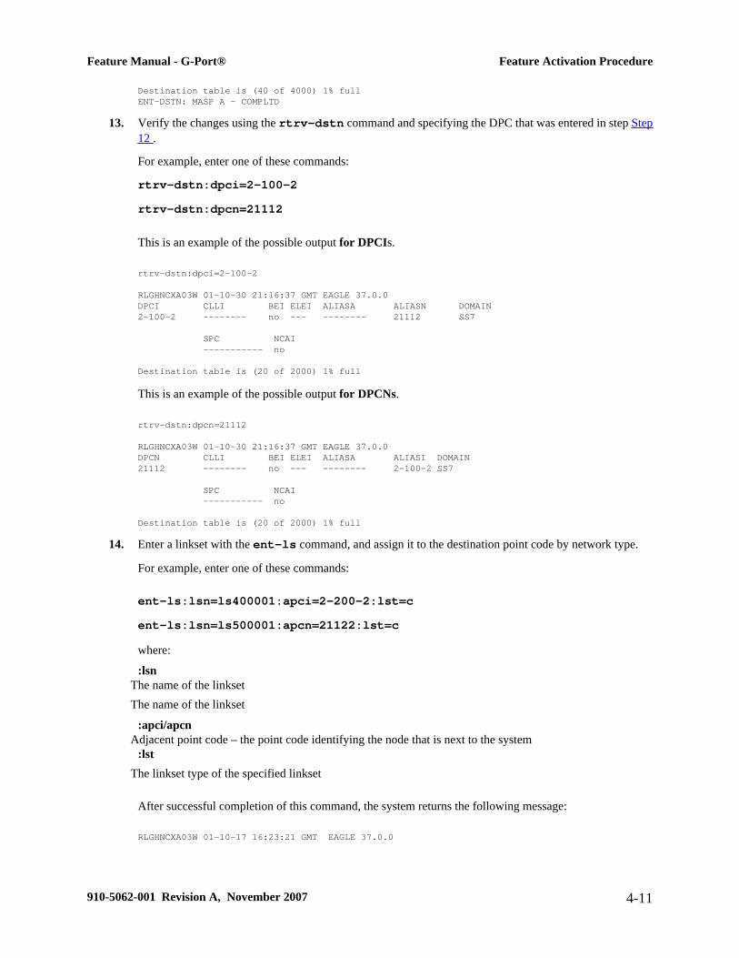
Destination table is (40 of 4000) 1% fullENT-DSTN: MASP A - COMPLTD
13. Verify the changes using the rtrv-dstn command and specifying the DPC that was entered in step Step12 .
For example, enter one of these commands:
rtrv-dstn:dpci=2-100-2rtrv-dstn:dpcn=21112
This is an example of the possible output for DPCIs.
rtrv-dstn:dpci=2-100-2
RLGHNCXA03W 01-10-30 21:16:37 GMT EAGLE 37.0.0DPCI CLLI BEI ELEI ALIASA ALIASN DOMAIN2-100-2 -------- no --- -------- 21112 SS7
SPC NCAI ----------- no
Destination table is (20 of 2000) 1% full
This is an example of the possible output for DPCNs.
rtrv-dstn:dpcn=21112
RLGHNCXA03W 01-10-30 21:16:37 GMT EAGLE 37.0.0DPCN CLLI BEI ELEI ALIASA ALIASI DOMAIN21112 -------- no --- -------- 2-100-2 SS7
SPC NCAI ----------- no
Destination table is (20 of 2000) 1% full
14. Enter a linkset with the ent-ls command, and assign it to the destination point code by network type.
For example, enter one of these commands:
ent-ls:lsn=ls400001:apci=2-200-2:lst=cent-ls:lsn=ls500001:apcn=21122:lst=cwhere:
:lsnThe name of the linksetThe name of the linkset
:apci/apcnAdjacent point code – the point code identifying the node that is next to the system
:lstThe linkset type of the specified linkset
After successful completion of this command, the system returns the following message:
RLGHNCXA03W 01-10-17 16:23:21 GMT EAGLE 37.0.0
Feature Manual - G-Port® Feature Activation Procedure
910-5062-001 Revision A, November 2007 4-11
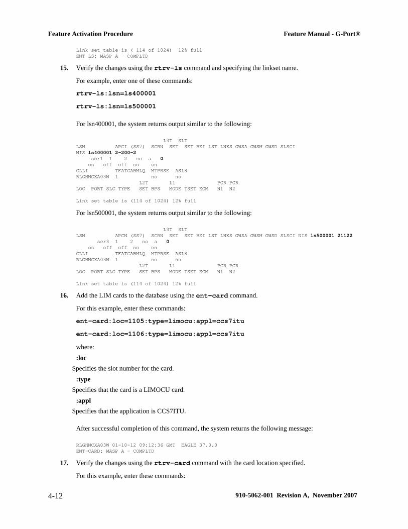
Link set table is ( 114 of 1024) 12% fullENT-LS: MASP A - COMPLTD
15. Verify the changes using the rtrv-ls command and specifying the linkset name.
For example, enter one of these commands:
rtrv-ls:lsn=ls400001rtrv-ls:lsn=ls500001
For lsn400001, the system returns output similar to the following:
L3T SLTLSN APCI (SS7) SCRN SET SET BEI LST LNKS GWSA GWSM GWSD SLSCI NIS ls400001 2-200-2 scr1 1 2 no a 0 on off off no onCLLI TFATCABMLQ MTPRSE ASL8RLGHNCXA03W 1 no no L2T L1 PCR PCRLOC PORT SLC TYPE SET BPS MODE TSET ECM N1 N2
Link set table is (114 of 1024) 12% full
For lsn500001, the system returns output similar to the following:
L3T SLTLSN APCN (SS7) SCRN SET SET BEI LST LNKS GWSA GWSM GWSD SLSCI NIS ls500001 21122 scr3 1 2 no a 0 on off off no onCLLI TFATCABMLQ MTPRSE ASL8RLGHNCXA03W 1 no no L2T L1 PCR PCRLOC PORT SLC TYPE SET BPS MODE TSET ECM N1 N2
Link set table is (114 of 1024) 12% full
16. Add the LIM cards to the database using the ent-card command.
For this example, enter these commands:
ent-card:loc=1105:type=limocu:appl=ccs7ituent-card:loc=1106:type=limocu:appl=ccs7ituwhere::loc
Specifies the slot number for the card.:type
Specifies that the card is a LIMOCU card.:appl
Specifies that the application is CCS7ITU.
After successful completion of this command, the system returns the following message:
RLGHNCXA03W 01-10-12 09:12:36 GMT EAGLE 37.0.0ENT-CARD: MASP A - COMPLTD
17. Verify the changes using the rtrv-card command with the card location specified.
For this example, enter these commands:
Feature Activation Procedure Feature Manual - G-Port®
4-12 910-5062-001 Revision A, November 2007

rtrv-card:loc=1105rtrv-card:loc=1106
Examples of the output from these commands follow:
RLGHNCXA03W 01-10-30 09:12:36 GMT EAGLE 37.0.0CARD TYPE APPL PORT A LSET (SLC) PORT B LSET (SLC)1105 LIMOCU CCS7ITU -------- (--) -------- (--)
RLGHNCXA03W 01-10-30 09:12:36 GMT EAGLE 37.0.0CARD TYPE APPL PORT A LSET (SLC) PORT B LSET (SLC)1106 LIMOCU CCS7ITU -------- (--) -------- (--)
18. Assign signaling links to the LIM cards using the ent-slk command.
For example, enter these commands:
ent-slk:loc=1105:port=a:lsn=ls400001:slc=0:l2tset=1ent-slk:loc=1106:port=a:lsn=ls500001:slc=0:l2tset=1where:
:locThe card location of the LIM that the SS7 signaling link will be assigned to.
:portThe port on the card specified in the loc parameter.
:lsnThe name of the linkset that will contain the signaling link.
:slcThe signaling link code. The slc must be unique within the linkset. It must be the same at both the systemlocation and the distant node.
:l2tsetThe level 2 timer set table. A signaling link may be assigned to any of the twenty tables.
After successful completion of this command, the system returns the following message:
RLGHNCXA03W 01-10-07 08:29:03 GMT EAGLE 37.0.0ENT-SLK: MASP A - COMPLTD
Signaling links are the only elements in the database directly supported by a hardware device. When a linkis added to a linkset, the link remains in the state OOS-MT-DSBLD (out of service maintenance disabled)until it is activated; see step Step 26 .
19. Verify the changes using the rtrv-slk command, specifying the card location and port of the signalinglink entered in step Step 18 .
rtrv-slk:loc=1105:port=artrv-slk:loc=1106:port=a
This is an example of the possible output.
RLGHNCXA03W 01-10-19 21:16:37 GMT EAGLE 37.0.0 L2T L1 PCR PCR
Feature Manual - G-Port® Feature Activation Procedure
910-5062-001 Revision A, November 2007 4-13

LOC PORT LSN SLC TYPE SET BPS MODE TSET ECM N1 N2 1105 A ls400001 0 LIMOCU 1 56000 --- --- BASIC --- -----
RLGHNCXA03W 01-10-19 21:16:37 GMT EAGLE 37.0.0 L2T L1 PCR PCRLOC PORT LSN SLC TYPE SET BPS MODE TSET ECM N1 N2 1106 A ls500001 0 LIMOCU 1 56000 --- --- BASIC --- -----
20. Add a route for the new DPC by network type using the ent-rte command.
For example, enter one of these commands:
ent-rte:dpci=2-100-2:lsn=ls400001:rc=10ent-rte:dpcn=21112:lsn=ls500001:rc=10where:
:dpci/dpcnDestination point code of the node that the traffic is bound for.
:lsnThe name of the linkset that will carry the traffic bound for the node specified by the destination point code.
:rcThe relative cost (priority) for this route.
After successful completion of this command, the system returns the following message:
RLGHNCXA03W 01-10-07 08:28:30 GMT EAGLE 37.0.0ENT-RTE: MASP A - COMPLTD
21. Verify the changes using the rtrv-rte command and specifying the destination point code of the route.
A sample output from this command follows:
rlghncxa03w 01-10-07 11:43:04 GMT EAGLE 37.0.0DPCA ALIASI ALIASN CLLI LSN RC APCA----------- ------- ------- ----- -------- -- ----------- DPCI ALIASN ALIASA CLLI LSN RC APCI2-100-1 121111 240-111-111 idp1 ls100001 10 1-234-5 ls100002 10 1-234-6 ls100003 20 1-234-7 ls100004 30 1-234-1 ls100005 40 1-234-2 ls100006 50 1-234-32-100-2 121111 240-111-111 idp1 ls400001 10 1-200-2
DPCN ALIASA ALIASI CLLI LSN RC APCN21111 011-222-111 0-001-1 ndp1 ls200001 10 11111 ls200002 10 11112 ls200003 20 11113 ls200004 30 11114 ls200005 40 11115 ls200006 50 1111621112 011-222-111 0-001-1 ndp1 ls500001 10 11122
22. Add a mated application to the database by network type using the ent-map command.
For this example, enter this command:
ent-map:pci=2-100-1:ssn=12:rc=20:mpci=3-200-1:mssn=50 :materc=99:grp=grp03ent-map:pcn=11112:ssn=12:rc=10:mpcn=11114:mssn=250:materc=99 :grp=grp07
Feature Activation Procedure Feature Manual - G-Port®
4-14 910-5062-001 Revision A, November 2007

where:
:pci/pcnThe point code of the primary signaling point that is to receive the message.
:ssnSubsystem number – the subsystem address of the primary point code that is to receive the message.
:rcThe relative cost.
:mpc/mpca/mpci/mpcnThe point code of the backup signaling point that is to receive the message.
:mssnMate subsystem number – the subsystem address of the backup point code that is to receive the message.
:matercMate relative cost.
:grpThe name of the concerned signaling point code group that contains the point codes that should be notifiedof the subsystem status. This parameter applies to both RPCs/SSNs.
When each of these commands have successfully completed, this message should appear.
RLGHNCXA03W 01-10-07 00:28:31 GMT EAGLE 37.0.0ENT-MAP: MASP A - COMPLTD
23. Verify the changes using the rtrv-map command.Examples of possible output from this command follow:
rlghncxa03w 01-10-07 11:43:04 GMT EAGLE 37.0.0PCN SSN RC MPCN MSSN MATERC SRM MRC GRP NAME11111 5 20 12347 250 99 --- --- GRP0711112 12 0 12347 250 99 --- --- GRP07
rlghncxa03w 01-10-07 11:43:04 GMT EAGLE 37.0.0PCI SSN RC MPCI MSSN MATERC SRM MRC GRP NAME1-100-1 5 0 3-200-1 250 99 --- --- GRP032-100-1 12 20 3-200-1 50 99 --- --- GRP03
24. Allow the LIM cards that were entered in step Step 16 by using the alw-card command.
For example, enter these commands:
alw-card:loc=1105alw-card:loc=1106
This message appears:
RLGHNCXA03W 01-10-30 21:20:37 GMT EAGLE 37.0.0Card has been allowed.
25. Verify the in-service normal (IS-NR) status of the cards using the rept-stat-card command.
A sample output from this command follows:
RLGHNCXA03W 01-10-27 16:43:42 GMT EAGLE 37.0.0CARD VERSION TYPE APPL PST SST AST
Feature Manual - G-Port® Feature Activation Procedure
910-5062-001 Revision A, November 2007 4-15

1101 100-000-00003-000 ASM SCCP IS-NR Active ---1102 100-000-00003-000 ASM SCCP IS-NR Active ---1103 100-000-00003-000 ACMENET STPLAN IS-NR Active ---1104 100-000-00003-000 ACMENET GLS IS-NR Active ---1105 100-000-00003-000 LIMOCU CCS7ITU IS-NR Active ---1106 100-000-00003-000 LIMOCU CCS7ITU IS-NR Active ---1113 100-000-00002-000 MCAP OAM IS-NR Active ---1114 100-000-00002-000 TDM IS-NR Active ---1115 100-000-00002-000 MCAP OAM IS-NR Active ---1116 100-000-00002-000 TDM IS-NR Active ---1117 100-000-00002-000 MDAL IS-NR Active ---1201 100-000-00003-000 LIMDS0 SS7ANSI IS-NR Active ---1202 100-000-00002-000 LIMV35 SS7GX25 IS-NR Active ---1203 100-000-00003-000 LIMV35 SS7ANSI IS-NR Active ---1204 100-000-00003-000 LIMATM ATMANSI IS-NR Active ---1205 100-000-00001-000 DCM IPLIM IS-NR Active ---1207 100-000-00001-000 DCM SS7IPGW IS-NR Active ---1303 100-000-00001-000 DCM IPLIM IS-NR Active ---1305 100-000-00001-000 DCM SS7IPGW IS-NR Active ---
26. Activate the signaling links entered in step Step 18 using the act-slk command.
For example, enter these commands:
act-slk:loc=1105:port=aact-slk:loc=1106:port=a
The link changes its state from OOS-MT-DSBLD (out-of-service maintenance-disabled) to IS-NR (in-servicenormal). The output confirms the activation.
RLGHNCXA03W 01-10-07 11:11:28 GMT EAGLE 37.0.0Activate Link message sent to card
27. Verify the in-service normal (IS-NR) status of the signaling link using the rept-stat-slk command.
For example, enter these commands:
rept-stat-slk:loc=1105rept-stat-slk:loc=1106
This message should appear.
RLGHNCXA03W 01-10-30 21:16:37 GMT EAGLE 37.0.0SLK LSN CLLI PST SST AST 1105,A ls400001 ---------- IS-NR Avail ----Command Completed.
RLGHNCXA03W 01-10-30 21:16:37 GMT EAGLE 37.0.0SLK LSN CLLI PST SST AST 1106,A ls500001 ---------- IS-NR Avail ----Command Completed.
28. Display the new LIM cards in the database using the rtrv-card command.
A sample output from this command follows:
RLGHNCXA03W 01-10-15 16:34:56 GMT EAGLE 37.0.0CARD TYPE APPL PORT A LSET (SLC) PORT B LSET (SLC)1101 ASM SCCP -------- (--) -------- (--)1102 ASM SCCP -------- (--) -------- (--)1103 ACMENET STPLAN -------- (--) -------- (--)1104 ACMENET GLS -------- (--) -------- (--)1105 LIMOCU CCS7ITU ls400001 ( 00) -------- (--)1106 LIMOCU CCS7ITU ls500001 ( 00) -------- (--)1113 MCAP OAM
Feature Activation Procedure Feature Manual - G-Port®
4-16 910-5062-001 Revision A, November 2007

1114 TDM1115 MCAP OAM1116 TDM1117 MDAL1201 LIMDS0 SS7ANSI lsn1 (00) lsn2 (01)1202 LIMV35 SS7GX25 lsngwy (00) -------- (--)1203 LIMV35 SS7ANSI lsn2 (00) lsn1 (01)1204 LIMATM ATMANSI atmgwy (00) -------- (--)1205 DCM IPLIM ipgwy1 (00) ipgwy3 (01)1207 DCM SS7IPGW ipgwy2 (00) -------- (--)1303 DCM IPLIM ipgwy1 (00) ipgwy3 (01)1305 DCM SS7IPGW ipgwy4 (00) -------- (--)
Determine a location where the double-slot DSM card can be inserted. The output shows slots 1107 and1108 are not occupied. Also determine adjacent (odd-even slots) SCCP cards for later TSM cardreplacements.
29. Install and configure DSM card(s) as needed in available odd-even slots using steps Step 30 through Step45 .
For our example, install a DSM card in slots 1107 and 1108.
30. Install the DSM card in slots 1107 and 1108.The DSM card requires two slots and must be installed in an odd slot with an adjacent empty even slot onits right side.
a. Open the ejector levers on the DSM card.Carefully align the card’s edges with the top and bottom card guides. Then push the card along thelength of the card guides until the rear connectors on the card engage the mating connectors on thetarget shelf backplane.
b. Press the left edge of the card’s faceplate using constant pressure until you feel the card’s progresscease.
WARNING: Do not impact the faceplate in order to mate the connectors. Anyimpact to the card’s faceplate can damage the faceplate, the pins, or the connectors.
c. Push in the top and bottom inject/eject clamps.This locks the card in place and ensures a strong connection with the pins on the target shelf backplane.
Figure 4-1. Push in Inject/Eject Clamps
Feature Manual - G-Port® Feature Activation Procedure
910-5062-001 Revision A, November 2007 4-17

d. Verify that both IMT bus LEDs are green.
e. Install the cabling required to connect the DSM card to the MPS.Refer to the Installation Manual for details.
31. Add the DSM card to the database and configure it as VSCCP card using the ent-card command.
For this example, enter this command:
ent-card:loc=1107:type=dsm:appl=vsccpwhere:
:locSpecifies the slot number for the card. The slot number must be an odd number.
:typeSpecifies that the card is a DSM card.
:applSpecifies that the application is VSCCP.
After successful completion of this command, the system returns the following message:
RLGHNCXA03W 01-10-12 09:12:36 GMT EAGLE 37.0.0ENT-CARD: MASP A - COMPLTD
32. Verify the VSCCP card using the rtrv-card command with the card location specified.
For this example, enter this command:
rtrv-card:loc=1107
A sample output from this command follows:
RLGHNCXA03W 01-10-30 09:12:36 GMT EAGLE 37.0.0CARD TYPE APPL PORT A LSET (SLC) PORT B LSET (SLC)1107 DSM VSCCP -------- (--) -------- (--)
33. Display the current link parameters associated with the VSCCP card in the database by entering the rtrv-ip-lnk command.
A sample output from this command follows:RLGHNCXA03W 01-10-30 21:14:37 GMT EAGLE 37.0.0 LOC PORT IPADDR SUBMASK DUPLEX SPEED MACTYPE AUTO MCAST 1107 A ------- -------- HALF 10 DIX NO NO 1107 B ------- -------- HALF 10 DIX NO NO
34. Enter the IP address port and speed associated with the VSCCP card in the database using the chg-ip-lnk command.
For this example, enter these commands:
chg-ip-lnk:loc=1107:port=a:duplex=half:ipaddrr=192.168.122.1:mactype=dix:speed=100:mcast=yes:submask=255.255.255.0chg-ip-lnk:loc=1107:port=b:duplex=half:ipaddrr=192.168.123.1:mactype=dix:speed=10:mcast=yes:submask=255.255.255.0
Feature Activation Procedure Feature Manual - G-Port®
4-18 910-5062-001 Revision A, November 2007

where:
:locThe card location of the VSCCP card within the EAGLE 5 ISS.
:portThe port ID. The port parameter of the chg-ip-lnk command specifies the physical interface of the DSM card.
:ipaddrIP address assigned to the port. This is a TCP/IP address expressed in standard "dot notation." IP addressesconsist of the system's network number and the machine's unique host number.
:duplexThis is the mode of operation of the interface.
:speedThis is interface bandwidth in megabits per second. The speed is either 100 Mbps for main DSM network or10 Mbps for backup DSM network.
:mactypeThis is the Media Access Control Type of the interface. Specify dix for the Digital/Inter/Xerox de factostandard for the Ethernet.
:mcastThis is the Multicast Control of the interface.
:submaskThe subnet mask of the IP interface, in the form of an IP address with a restricted range of values.
When this command has successfully completed, the following message appears:RLGHNCXA03W 01-10-30 21:18:37 GMT EAGLE 37.0.0 CHG-IP-LNK: MASP A - COMPLTD
35. Verify the IP address port and speed associated with the VSCCP card in the database by entering the rtrv-ip-lnk command.
A sample output from this command follows:RLGHNCXA03W 01-10-30 21:14:37 GMT EAGLE 37.0.0 LOC PORT IPADDR SUBMASK DUPLEX SPEED MACTYPE AUTO MCAST 1107 A 192.168.122.1 255.255.255.0 HALF 100 DIX NO YES 1107 B 192.168.123.1 255.255.255.0 HALF 10 DIX NO YES
36. Display the current IP host information in the database by entering the rtrv-ip-host command.
A sample output from this command follows:
RLGHNCXA03W 01-10-30 21:17:37 GMT EAGLE 37.0.0
IPADDR HOST192.1.1.32 KC_HLR2192.1.1.50 DN_MSC1192.1.1.52 DN_MSC2
37. Add the host name and IP address for each VSCCP link using the ent-ip-host command.
For example, enter these commands:
ent-ip-host:host=vsccp_1107_a:ipaddr=192.168.122.1ent-ip-host:host=vsccp_1107_b:ipaddr=192.168.123.1
Feature Manual - G-Port® Feature Activation Procedure
910-5062-001 Revision A, November 2007 4-19

where:
:hostSpecifies the host name. Each VSCCP link must be specified separately.
:ipaddrSpecifies the IP network address for each EPAP. The first three octets of the IP address must be the same asMPS A and B ports, respectively. The fourth octet identifies the DSM card and must have a a unique octetidentifier for the card’s IP address; we recommend numbering the DSM cards sequentially, using values 1 to25. (This example shows the assignment of the first DSM card.)
After successful completion of this command, the system returns the following message:
RLGHNCXA03W 01-10-30 21:18:37 GMT EAGLE 37.0.0ENT-IP-HOST: MASP A - COMPLTD
38. Verify the new IP host information in the database by entering the rtrv-ip-host command.
The following is an example of the possible output.
RLGHNCXA03W 01-10-30 21:19:37 GMT EAGLE 37.0.0
IPADDR HOST192.1.1.32 KC_HLR2192.1.1.50 DN_MSC1192.1.1.52 DN_MSC2192.168.122.1 VSCCP_1107_A192.168.123.1 VSCCP_1107_B
NOTE: Most G-Port customer private networks do not require setting up a default routerfor the DSM card. However, if your network configuration does require a default routerto connect the DSM card communication to the EPAP, then only one default router isassignable to each DSM card. Assign the default router address to each DSM card asshown in this step.
39. Enter local domain and IP router address for the VSCCP card using the chg-ip-card command.
For this example, enter this command:
chg-ip-card:loc=1107:domain=nc.tekelec.com :defrouter=192.168.122.250where:
:locThe location of the VSCCP card within the EAGLE 5 ISS.
:domainThe domain name of domain server.
:defrouterDefault router address. The IP address for default router. This is a TCP/IP address expressed in standard “dotnotation”. IP addresses consist of the system’s network number and the machine’s unique host number.
After successful completion of this command, the system returns the following message:
RLGHNCXA03W 01-10-30 21:20:37 GMT EAGLE 37.0.0CHG-IP-CARD: MASP A - COMPLTD
40. Verify the new TCP/IP parameters associated with the VSCCP card in the database by entering the rtrv-ip-card command.
Feature Activation Procedure Feature Manual - G-Port®
4-20 910-5062-001 Revision A, November 2007

A sample output from this command follows:
RLGHNCXA03W 01-10-30 21:21:37 GMT EAGLE 37.0.0 LOC 1107 SRCHORDR LOCAL DNSA ----------- DNSB ----------- DEFROUTER 192.168.122.250 DOMAIN NC.TEKELEC.COM
41. Boot the DSM card that was added in step Step 31 in TSM emulation mode by using the alw-cardcommand.
For example, enter this command:
alw-card:loc=1107
This message appears:
RLGHNCXA03W 01-10-30 21:20:37 GMT EAGLE 37.0.0Card has been allowed.
42. Verify the in-service normal (IS-NR) status of the VSCCP card using the rept-stat-card command.
This is an example of the possible output.
RLGHNCXA03W 01-10-27 16:43:42 GMT EAGLE 37.0.0CARD VERSION TYPE APPL PST SST AST1101 100-000-00003-000 ASM SCCP IS-NR Active ---1102 100-000-00003-000 ASM SCCP IS-NR Active ---1103 100-000-00002-000 ACMENET STPLAN IS-NR Active ---1104 100-000-00003-000 ASM GLS IS-NR Active ---1105 100-000-00003-000 LIMOCU CCS7ITU IS-NR Active ---1106 100-000-00003-000 LIMOCU CCS7ITU IS-NR Active ---1107 100-000-00003-000 DSM VSCCP IS-NR Active ---1113 100-000-00002-000 MCAP OAM IS-NR Active ---1114 100-000-00002-000 TDM IS-NR Active ---1115 100-000-00002-000 MCAP OAM IS-NR Active ---1116 100-000-00002-000 TDM IS-NR Active ---1117 100-000-00002-000 MDAL IS-NR Active ---1201 100-000-00003-000 LIMDS0 SS7ANSI IS-NR Active ---1202 100-000-00002-000 LIMV35 SS7GX25 IS-NR Active ---1203 100-000-00003-000 LIMV35 SS7ANSI IS-NR Active ---1204 100-000-00003-000 LIMATM ATMANSI IS-NR Active ---1205 100-000-00001-000 DCM IPLIM IS-NR Active ---1207 100-000-00001-000 DCM SS7IPGW IS-NR Active ---1303 100-000-00001-000 DCM IPLIM IS-NR Active ---1305 100-000-00001-000 DCM SS7IPGW IS-NR Active ---
43. Test the presence of the EPAP hosts on the network using the pass command with the ping parameter.
This command is invoked with a destination (either a hostname or IP address). For example, enter thefollowing command:
pass:loc=1107:cmd=”ping 192.168.122.100”.pass:loc=1107:cmd=”ping 192.168.122.200”.pass:loc=1107:cmd=”ping 192.168.123.100”.pass:loc=1107:cmd=”ping 192.168.123.200”.
Feature Manual - G-Port® Feature Activation Procedure
910-5062-001 Revision A, November 2007 4-21

After successful completion of each command, the system returns output similar to the following:
rlghncxa03w 00-06-27 08:30:44 GMT EAGLE 37.0.0pass: loc=1107: cmd="ping 192.168.122.100"Command entered at terminal #1.;rlghncxa03w 00-06-27 08:30:44 GMT EAGLE 37.0.0PASS: Command sent to card;rlghncxa03w 00-06-27 08:30:44 GMT EAGLE 37.0.0PING command in progress;rlghncxa03w 00-06-27 08:30:46 GMT EAGLE 37.0.0PING 192.168.122.100: 56 data bytes64 bytes from tekral.nc.tekelec.com (192.168.122.100):icmp_seq=0.time=5. ms64 bytes from tekral.nc.tekelec.com (192.168.122.100):icmp_seq=1.time=0. ms64 bytes from tekral.nc.tekelec.com (192.168.122.100):icmp_seq=2.time=0. ms----192.168.100.3 PING Statistics----3 packets transmitted, 3 packets received, 0% packet lossround-trip (ms) min/avg/max = 0/1/5PING command complete
If the pass commands with the ping parameter is not successful, verify the the correct connection of thehardware cabling and try again. If the command fails again, contact the Customer Care Center .
44. Repeat steps Step 30 through Step 43 to add all DSM cards (N+1) to be installed in available slots.Go to Step Step 45 to start replacing TSM cards with DSM cards.
45. Replace TSM card(s) with DSM cards if applicable and add DSM card(s) to the database using steps Step45 through Step 70 .In this procedure, we are removing two existing adjacent TSM cards and replace them with a double-slotDSM card in slots 1101 and 1102.
NOTE: When adding DSM cards in an in-service environment, you must take care notto interrupt traffic. Before replacing SCCP cards with DSMs, first install a VSCCP cardin an available double-slot.
46. Display the TSM cards running the SCCP application in the database using the rtrv-card command.
A sample output from this command follows:
RLGHNCXA03W 01-10-15 16:34:56 GMT EAGLE 37.0.0CARD TYPE APPL PORT A LSET (SLC) PORT B LSET (SLC)1101 ASM SCCP -------- (--) -------- (--) 1102 ASM SCCP -------- (--) -------- (--)1103 ACMENET STPLAN -------- (--) -------- (--)1104 ACMENET GLS -------- (--) -------- (--)1105 LIMOCU CCS7ITU ls300001 (00) -------- (--)1106 LIMOCU CCS7ITU ls400001 (00) -------- (--)1107 DSM VSCCP ls300001 (00) -------- (--)1113 MCAP OAM1114 TDM1115 MCAP OAM1116 TDM1117 MDAL1201 LIMDS0 SS7ANSI lsn1 (00) lsn2 (01)1202 LIMV35 SS7GX25 lsngwy (00) -------- (--)1203 LIMV35 SS7ANSI lsn2 (00) lsn1 (01)1204 LIMATM ATMANSI atmgwy (00) -------- (--)1205 DCM IPLIM ipgwy1 (00) ipgwy3 (01)1207 DCM SS7IPGW ipgwy2 (00) -------- (--)1303 DCM IPLIM ipgwy1 (00) ipgwy3 (01)1305 DCM SS7IPGW ipgwy4 (00) -------- (--)
Feature Activation Procedure Feature Manual - G-Port®
4-22 910-5062-001 Revision A, November 2007

Determine the cards to be removed from the database. In this procedure, we will remove the SCCP cards incard locations 1101 and 1102.
47. Display the SCCP cards that are in service with the rept-stat-card:stat=nr command.
For this example, enter the following command:
rept-stat-card:stat=nr
A sample output from this command follows:
RLGHNCXA03W 01-10-27 16:43:42 GMT EAGLE 37.0.0CARD VERSION TYPE APPL PST SST AST1101 100-000-00003-000 ASM SCCP IS-NR Active ---1102 100-000-00003-000 ASM SCCP IS-NR Active ---1103 100-000-00003-000 ACMENET STPLAN IS-NR Active ---1104 100-000-00003-000 ACMENET GLS IS-NR Active ---1105 100-000-00003-000 LIMOCU CCS7ITU IS-NR Active ---1106 100-000-00003-000 LIMOCU CCS7ITU IS-NR Active ---1107 100-000-00003-000 DSM VSCCP IS-NR Active ---1113 100-000-00002-000 MCAP OAM IS-NR Active ---1114 100-000-00002-000 TDM IS-NR Active ---1115 100-000-00002-000 MCAP OAM IS-NR Active ---1116 100-000-00002-000 TDM IS-NR Active ---1117 100-000-00002-000 MDAL IS-NR Active ---1201 100-000-00003-000 LIMDS0 SS7ANSI IS-NR Active ---1202 100-000-00002-000 LIMV35 SS7GX25 IS-NR Active ---1203 100-000-00003-000 LIMV35 SS7ANSI IS-NR Active ---1204 100-000-00003-000 LIMATM ATMANSI IS-NR Active ---1205 100-000-00001-000 DCM IPLIM IS-NR Active ---1207 100-000-00001-000 DCM SS7IPGW IS-NR Active ---1303 100-000-00001-000 DCM IPLIM IS-NR Active ---1305 100-000-00001-000 DCM SS7IPGW IS-NR Active ---
48. Inhibit the SCCP cards using the inh-card command and specifying the card locations.
inh-card:loc=1101inh-card:loc=1102
When each command has successfully completed, this message appears:
RLGHNCXA03W 01-10-12 09:12:36 GMT EAGLE 37.0.0Card has been inhibited.
49. Verify that the SCCP cards are in the Out-of-Service Maintenance-Disabled (OOS-MT-DSBLD) state withthe rept-stat-card command.
A sample output from this command follows:
RLGHNCXA03W 01-10-27 16:43:42 GMT EAGLE 37.0.0CARD VERSION TYPE APPL PST SST AST1101 100-000-00003-000 ASM SCCP OOS-MT-DSBLD Isolated ---1102 100-000-00003-000 ASM SCCP OOS-MT-DSBLD Isolated ---1103 100-000-00002-000 ACMENET STPLAN IS-NR Active ---1104 100-000-00002-000 ACMENET STPLAN IS-NR Active ---1105 100-000-00003-000 LIMOCU CCS7ITU IS-NR Active ---1106 100-000-00003-000 LIMOCU CCS7ITU IS-NR Active ---1107 100-000-00003-000 DSM VSCCP IS-NR Active ---1113 100-000-00002-000 MCAP OAM IS-NR Active ---1114 100-000-00002-000 TDM IS-NR Active ---1115 100-000-00002-000 MCAP OAM IS-NR Active ---1116 100-000-00002-000 TDM IS-NR Active ---1117 100-000-00002-000 MDAL IS-NR Active ---1201 100-000-00003-000 LIMDS0 SS7ANSI IS-NR Active ---1202 100-000-00002-000 LIMV35 SS7GX25 IS-NR Active ---
Feature Manual - G-Port® Feature Activation Procedure
910-5062-001 Revision A, November 2007 4-23
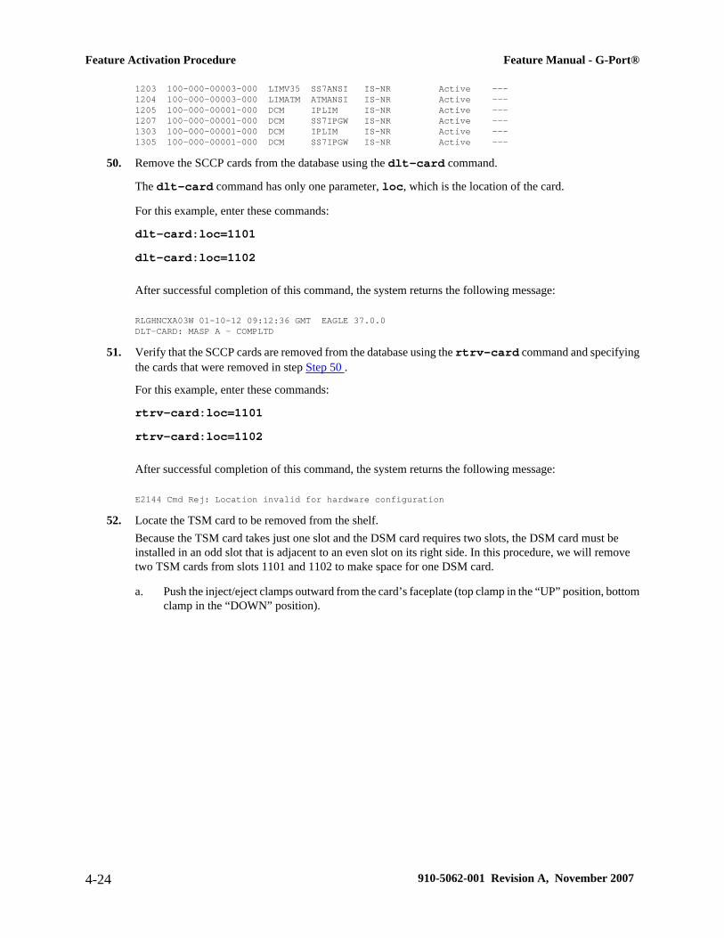
1203 100-000-00003-000 LIMV35 SS7ANSI IS-NR Active ---1204 100-000-00003-000 LIMATM ATMANSI IS-NR Active ---1205 100-000-00001-000 DCM IPLIM IS-NR Active ---1207 100-000-00001-000 DCM SS7IPGW IS-NR Active ---1303 100-000-00001-000 DCM IPLIM IS-NR Active ---1305 100-000-00001-000 DCM SS7IPGW IS-NR Active ---
50. Remove the SCCP cards from the database using the dlt-card command.
The dlt-card command has only one parameter, loc, which is the location of the card.
For this example, enter these commands:
dlt-card:loc=1101dlt-card:loc=1102
After successful completion of this command, the system returns the following message:
RLGHNCXA03W 01-10-12 09:12:36 GMT EAGLE 37.0.0DLT-CARD: MASP A - COMPLTD
51. Verify that the SCCP cards are removed from the database using the rtrv-card command and specifyingthe cards that were removed in step Step 50 .
For this example, enter these commands:
rtrv-card:loc=1101rtrv-card:loc=1102
After successful completion of this command, the system returns the following message:
E2144 Cmd Rej: Location invalid for hardware configuration
52. Locate the TSM card to be removed from the shelf.Because the TSM card takes just one slot and the DSM card requires two slots, the DSM card must beinstalled in an odd slot that is adjacent to an even slot on its right side. In this procedure, we will removetwo TSM cards from slots 1101 and 1102 to make space for one DSM card.
a. Push the inject/eject clamps outward from the card’s faceplate (top clamp in the “UP” position, bottomclamp in the “DOWN” position).
Feature Activation Procedure Feature Manual - G-Port®
4-24 910-5062-001 Revision A, November 2007

Figure 4-2. Push Inject/Eject Clamps Outward
b. Pull the levers away from the shelf until they are parallel to the floor.
c. Gently pull the card towards you until the card clears the shelf
d. Place the card you have removed in an electrostatic discharge (ESD) protective container, or place thecard in the spare card storage shelf.
53. Repeat step Step 52 to remove the second TSM card.54. Install the DSM card in slots 1101 and 1102.
a. Open the ejector levers on the DSM card.Carefully align the card’s edges with the top and bottom card guides. Then push the card along thelength of the card guides until the rear connectors on the card engage the mating connectors on thetarget shelf backplane.
b. Press the left edge of the card’s faceplate using constant pressure until you feel the card’s progresscease.
WARNING: Do not impact the faceplate in order to mate the connectors. Anyimpact to the card’s faceplate can damage the faceplate, the pins, or the connectors.
c. Push in the top and bottom inject/eject clamps.This locks the card in place and ensures a strong connection with the pins on the target shelf backplane.
Feature Manual - G-Port® Feature Activation Procedure
910-5062-001 Revision A, November 2007 4-25

Figure 4-3. Push in Inject/Eject Clamps
d. Verify that both IMT bus LEDs are green.
e. Install the cabling required to connect the DSM card to the MPS.Refer to the Installation Manual for details.
55. Add the DSM card to the database and assign the VSCCP application using the ent-card command.
For this example, enter this command:
ent-card:loc=1101:type=dsm:appl=vsccpwhere:
:locSpecifies the slot number for the card. The slot number must be an odd number.
:typeSpecifies that the card is a DSM card.
:applSpecifies that the application is VSCCP.
After successful completion of this command, the system returns the following message:
RLGHNCXA03W 01-10-12 09:12:36 GMT EAGLE 37.0.0ENT-CARD: MASP A - COMPLTD
56. Display the new VSCCP card using the rtrv-card command with the card location specified.
For this example, enter this command:
rtrv-card:loc=1101
A sample output from this command follows:
RLGHNCXA03W 01-10-30 09:12:36 GMT EAGLE 37.0.0CARD TYPE APPL PORT A LSET (SLC) PORT B LSET (SLC)1101 DSM VSCCP -------- (--) -------- (--)
Feature Activation Procedure Feature Manual - G-Port®
4-26 910-5062-001 Revision A, November 2007

57. Display the current link parameters associated with the VSCCP card in the database by entering the rtrv-ip-lnk command.
A sample output from this command follows:RLGHNCXA03W 01-10-30 21:14:37 GMT EAGLE 37.0.0 LOC PORT IPADDR SUBMASK DUPLEX SPEED MACTYPE AUTO MCAST 1101 A -------- --------- HALF 10 DIX NO NO 1101 B -------- --------- HALF 10 DIX NO NO 1107 A -------- --------- HALF 10 DIX NO NO 1107 B -------- --------- HALF 10 DIX NO NO
58. Change the link parameters associated with the VSCCP card in the database using the chg-ip-lnk command.
For this example, enter these commands:
chg-ip-lnk:loc=1101:port=a:duplex=half:ipaddrr=192.168.122.2 :mactype=dix:speed=100:mcast=yes:submask=255.255.255.0
chg-ip-lnk:loc=1101:port=b:duplex=half:ipaddrr=192.168.123.2 :mactype=dix:speed=10:mcast=yes:submask=255.255.255.0
where:
:locThe card location of the card within the EAGLE 5 ISS.
:portThe port ID. The port parameter of the chg-ip-lnk command specifies the physical interface of the DSM card.
:ipaddrIP address assigned to the port. This is a TCP/IP address expressed in standard "dot notation." IP addressesconsist of the system's network number and the machine's unique host number.
:duplexThis is the mode of operation of the interface.
:speedThis is interface bandwidth in megabits per second. The speed is either 100 Mbps for main DSM network or10 Mbps for backup DSM network.
:mactypeThis is the Media Access Control Type of the interface. Specify dix for the Digital/Inter/Xerox de factostandard for the Ethernet.
:mcastThis is the Multicast Control of the interface.
:submaskThe subnet mask of the IP interface, in the form of an IP address with a restricted range of values.
When this command has successfully completed, the following message should appear.RLGHNCXA03W 01-10-30 21:18:37 GMT EAGLE 37.0.0 CHG-IP-LNK: MASP A - COMPLTD
59. Verify the new link parameters associated with the VSCCP card in the database by entering the rtrv-ip-lnk command.
The following is an example of the possible output.
Feature Manual - G-Port® Feature Activation Procedure
910-5062-001 Revision A, November 2007 4-27
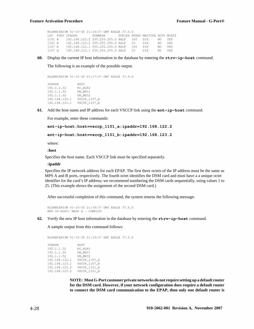
RLGHNCXA03W 01-10-30 21:14:37 GMT EAGLE 37.0.0 LOC PORT IPADDR SUBMASK DUPLEX SPEED MACTYPE AUTO MCAST1101 A 192.168.122.2 255.255.255.0 HALF 100 DIX NO YES 1101 B 192.168.123.2 255.255.255.0 HALF 10 DIX NO YES 1107 A 192.168.122.1 255.255.255.0 HALF 100 DIX NO YES 1107 B 192.168.123.1 255.255.255.0 HALF 10 DIX NO YES
60. Display the current IP host information in the database by entering the rtrv-ip-host command.
The following is an example of the possible output.
RLGHNCXA03W 01-10-30 21:17:37 GMT EAGLE 37.0.0
IPADDR HOST192.1.1.32 KC_HLR2192.1.1.50 DN_MSC1192.1.1.52 DN_MSC2192.168.122.1 VSCCP_1107_A192.168.123.1 VSCCP_1107_B
61. Add the host name and IP address for each VSCCP link using the ent-ip-host command.
For example, enter these commands:
ent-ip-host:host=vsccp_1101_a:ipaddr=192.168.122.2ent-ip-host:host=vsccp_1101_b:ipaddr=192.168.123.2where:
:hostSpecifies the host name. Each VSCCP link must be specified separately.
:ipaddrSpecifies the IP network address for each EPAP. The first three octets of the IP address must be the same asMPS A and B ports, respectively. The fourth octet identifies the DSM card and must have a a unique octetidentifier for the card’s IP address; we recommend numbering the DSM cards sequentially, using values 1 to25. (This example shows the assignment of the second DSM card.)
After successful completion of this command, the system returns the following message:
RLGHNCXA03W 01-10-30 21:18:37 GMT EAGLE 37.0.0ENT-IP-HOST: MASP A - COMPLTD
62. Verify the new IP host information in the database by entering the rtrv-ip-host command.
A sample output from this command follows:
RLGHNCXA03W 01-10-30 21:19:37 GMT EAGLE 37.0.0
IPADDR HOST192.1.1.32 KC_HLR2192.1.1.50 DN_MSC1192.1.1.52 DN_MSC2192.168.122.1 VSCCP_1107_A192.168.123.1 VSCCP_1107_B192.168.122.2 VSCCP_1101_A192.168.123.2 VSCCP_1101_B
NOTE: Most G-Port customer private networks do not require setting up a default routerfor the DSM card. However, if your network configuration does require a default routerto connect the DSM card communication to the EPAP, then only one default router is
Feature Activation Procedure Feature Manual - G-Port®
4-28 910-5062-001 Revision A, November 2007

assignable to each DSM card. Assign the default router address to each DSM card asshown in step Step 63 .
63. Enter local domain and IP router address for the VSCCP card using the chg-ip-card command.
For this example, enter this command:
chg-ip-card:loc=1107:domain=nc.tekelec.com :defrouter=192.168.122.250where:
:locThe card location of the card within the EAGLE 5 ISS.
:domainThe domain name of domain server.
:defrouterDefault router address. The IP address for default router. This is a TCP/IP address expressed in standard “dotnotation”. IP addresses consist of the system’s network number and the machine’s unique host number.
After successful completion of this command, the system returns the following message:
RLGHNCXA03W 01-10-30 21:20:37 GMT EAGLE 37.0.0CHG-IP-CARD: MASP A - COMPLTD
64. Boot the DSM card that was inhibited in step Step 48 in TSM emulation mode by using the alw-cardcommand.
For example, enter this command:
alw-card:loc=1101
This message appears:
RLGHNCXA03W 01-10-30 21:20:37 GMT EAGLE 37.0.0Card has been allowed.
65. Verify the local domain and IP router address associated with the VSCCP card in the database by enter thertrv-ip-card command.
A sample output from this command follows:RLGHNCXA03W 01-10-30 21:21:37 GMT EAGLE 37.0.0CHG-IP-CARD: MASP A - COMPLTD
66. Verify the in-service normal (IS-NR) status of the VSCCP card using the rept-stat-card command.
A sample output from this command follows:
RLGHNCXA03W 01-10-27 16:43:42 GMT EAGLE 37.0.0CARD VERSION TYPE APPL PST SST AST1101 100-000-00003-000 DSM VSCCP IS-NR Active ---1103 100-000-00002-000 ACMENET STPLAN IS-NR Active ---1104 100-000-00003-000 ASM GLS IS-NR Active ---1105 100-000-00003-000 LIMOCU CCS7ITU IS-NR Active ---1106 100-000-00003-000 LIMOCU CCS7ITU IS-NR Active ---1107 100-000-00003-000 DSM VSCCP IS-NR Active ---1113 100-000-00002-000 MCAP OAM IS-NR Active ---1114 100-000-00002-000 TDM IS-NR Active ---1115 100-000-00002-000 MCAP OAM IS-NR Active ---1116 100-000-00002-000 TDM IS-NR Active ---1117 100-000-00002-000 MDAL IS-NR Active ---
Feature Manual - G-Port® Feature Activation Procedure
910-5062-001 Revision A, November 2007 4-29
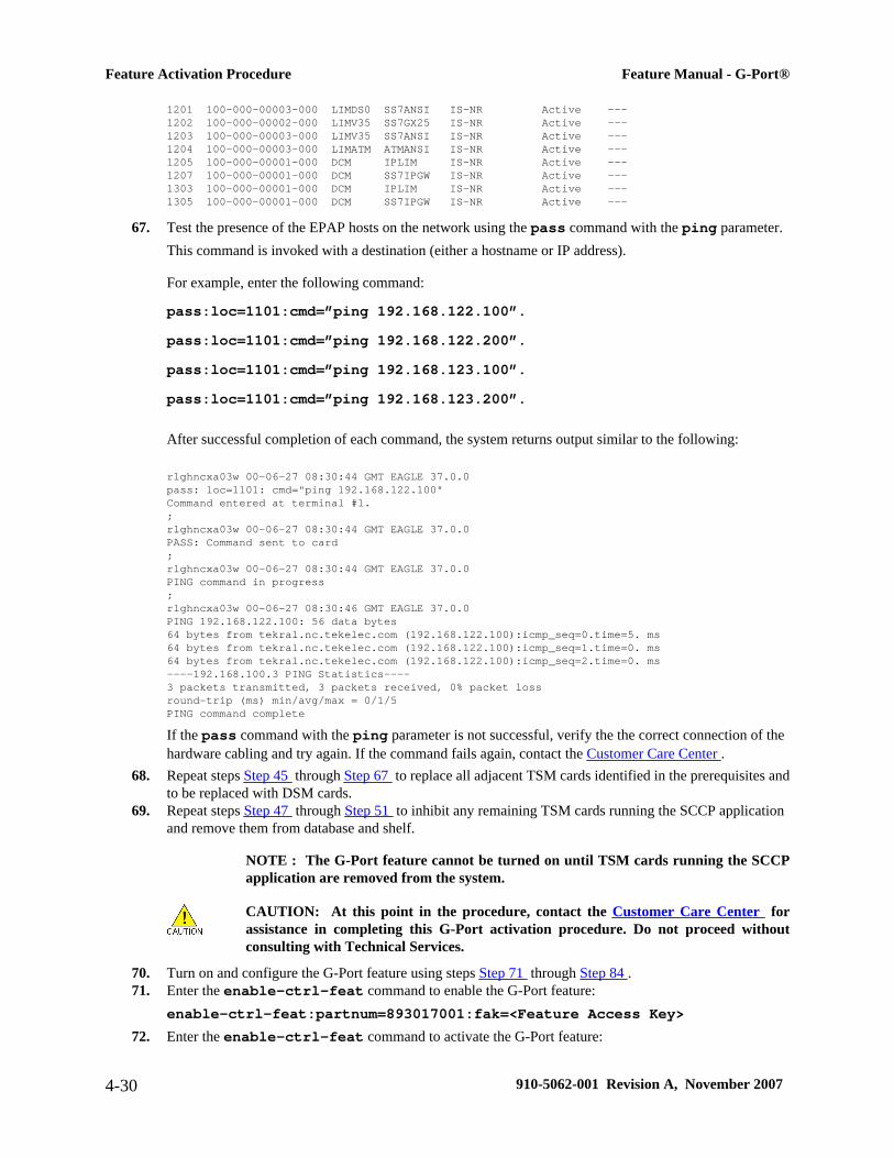
1201 100-000-00003-000 LIMDS0 SS7ANSI IS-NR Active ---1202 100-000-00002-000 LIMV35 SS7GX25 IS-NR Active ---1203 100-000-00003-000 LIMV35 SS7ANSI IS-NR Active ---1204 100-000-00003-000 LIMATM ATMANSI IS-NR Active ---1205 100-000-00001-000 DCM IPLIM IS-NR Active ---1207 100-000-00001-000 DCM SS7IPGW IS-NR Active ---1303 100-000-00001-000 DCM IPLIM IS-NR Active ---1305 100-000-00001-000 DCM SS7IPGW IS-NR Active ---
67. Test the presence of the EPAP hosts on the network using the pass command with the ping parameter.This command is invoked with a destination (either a hostname or IP address).
For example, enter the following command:
pass:loc=1101:cmd=”ping 192.168.122.100”.pass:loc=1101:cmd=”ping 192.168.122.200”.pass:loc=1101:cmd=”ping 192.168.123.100”.pass:loc=1101:cmd=”ping 192.168.123.200”.
After successful completion of each command, the system returns output similar to the following:
rlghncxa03w 00-06-27 08:30:44 GMT EAGLE 37.0.0pass: loc=1101: cmd="ping 192.168.122.100"Command entered at terminal #1.;rlghncxa03w 00-06-27 08:30:44 GMT EAGLE 37.0.0PASS: Command sent to card;rlghncxa03w 00-06-27 08:30:44 GMT EAGLE 37.0.0PING command in progress;rlghncxa03w 00-06-27 08:30:46 GMT EAGLE 37.0.0PING 192.168.122.100: 56 data bytes64 bytes from tekral.nc.tekelec.com (192.168.122.100):icmp_seq=0.time=5. ms64 bytes from tekral.nc.tekelec.com (192.168.122.100):icmp_seq=1.time=0. ms64 bytes from tekral.nc.tekelec.com (192.168.122.100):icmp_seq=2.time=0. ms----192.168.100.3 PING Statistics----3 packets transmitted, 3 packets received, 0% packet lossround-trip (ms) min/avg/max = 0/1/5PING command complete
If the pass command with the ping parameter is not successful, verify the the correct connection of thehardware cabling and try again. If the command fails again, contact the Customer Care Center .
68. Repeat steps Step 45 through Step 67 to replace all adjacent TSM cards identified in the prerequisites andto be replaced with DSM cards.
69. Repeat steps Step 47 through Step 51 to inhibit any remaining TSM cards running the SCCP applicationand remove them from database and shelf.
NOTE : The G-Port feature cannot be turned on until TSM cards running the SCCPapplication are removed from the system.
CAUTION: At this point in the procedure, contact the Customer Care Center forassistance in completing this G-Port activation procedure. Do not proceed withoutconsulting with Technical Services.
70. Turn on and configure the G-Port feature using steps Step 71 through Step 84 .71. Enter the enable-ctrl-feat command to enable the G-Port feature:
enable-ctrl-feat:partnum=893017001:fak=<Feature Access Key>72. Enter the enable-ctrl-feat command to activate the G-Port feature:
Feature Activation Procedure Feature Manual - G-Port®
4-30 910-5062-001 Revision A, November 2007

chg-ctrl-feat:partnum=893017001:status=on73. Enter the default country code (CC) and default network destination code (NDC) to convert the nature of
address indicator (NAI) of MSISDNs to the international format (nai=intl) with the chg-stpoptscommand.
For example, enter this command:
chg-stpopts:defcc=1:defndc=38:dsmaud=on:npcfmti=2-9-2-1where:
:defccThe default country code.
:defndcThe default network destination code.
:dsmaudThe DSM audit running state (on or off).
:npcfmt1The ITU National Point Code Format Identifier, which identifies how the ITU-N point code is entered intothe database and how it is displayed in all EAGLE 5 ISS outputs. This code is a 14-bit integer.
After successful completion of this command, the system returns the following output:
rlghncxa03w 01-10-07 00:57:31 GMT EAGLE 37.0.0CHG-STPOPTS: MASP A - COMPLTD
74. Verify the new country code and network destination code using the rtrv-stpopts command.
A sample output from this command follows:
rlghncxa03w 01-10-07 00:57:31 GMT EAGLE 37.0.0STP OPTIONS -----------------------NPCFMTI 2-9-2-1 DEFCC 1 DEFNDC 38 DSMAUD on
75. Change the GSM system options in the database.
For example, enter this command:
chg-gsmopts:srfnai=7:srfaddr=23448:srfnp=15 :msrsndig=ccrndn:defmapvr=2where:
:srfnaiDefines the nature of address indicator value of the MNP_SRF.
:srfaddrDefines the entity address of the MNP_SRF node.
:srfnpDefines the numbering plan value of the MNP_SRF.
:msrsndigDefines the routing number to be used or to be concatenated with the MSISDN.
Feature Manual - G-Port® Feature Activation Procedure
910-5062-001 Revision A, November 2007 4-31

:defmapvrDefines the default MAP version.
The system returns the following message:
rlghncxa03w 00-08-20 09:04:14 GMT EAGLE 37.0.0CHG-GSMOPTS: MASP A - COMPLTD
76. Verify the changes using the rtrv-gsmopts command.This command displays all GSM system options from the database.
A sample output from this command follows:
rlghncxa03w 00-08-20 09:04:14 GMT EAGLE 37.0.0GSMOPT OPTIONS -----------------------SRFADDR=23448 SRFNAI=7 SRFNP=15MSRNDIG=CCRNDNMSRNNAI=7 MSRNNP=15 DEFMAPVR=2
77. Add routing number prefixes for the operating network using the ent-homern command.Use this command to enter any Home RNs that are prefixed to DNs for incoming INPMR messages. Youmay use this command to enter up to 100 routing number prefixes for the operating network into theHOMERN table.
For example, enter this command:
ent-homern:rn=34where::rn
The home routing number prefix. The range is 1 to 15 hex digits (0-F).
When this command has successfully completed, this message appears.
RLGHNCXA03W 01-10-07 00:28:31 GMT EAGLE 37.0.0HOMERN table is (1 of 100) 1% full ENT-HOMERN: MASP A - COMPLTD
78. Verify the changes using the rtrv-homern command.This command retrieves a list of routing number prefixes that belong to the operating network.
Here is an example of the possible output.
rlghncxa03w 01-10-28 00:29:31 GMT EAGLE 37.0.0.0RN ---------------- 21678090908765476345098c10234567c222cabadeabcabc123
HOMERN table is (6 of 100) 6% full
79. Verify the changes using the rtrv-srvsel command.This command retrieves the object associated with the GSM (Global System for Mobile Telecommunication)subsystem number from the database. This command reads the GSMSSN table.
Feature Activation Procedure Feature Manual - G-Port®
4-32 910-5062-001 Revision A, November 2007

A sample output from this command follows:
rlghncxa03w 00-06-20 09:09:14 GMT EAGLE 37.0.0GTII TT NP NAI NPV NAIV SSN SNP SNAI SERV4 1 e214 intl --- --- 3 --- --- gport
80. Use the ent-srvsel command to enter the G-Port service selectors by network type. This command assigns applicable service selectors required to specify the service entry for DSM services.
For example, enter the following command:
ent-srvsel:gtii=4:tt=1:snp=e164:snai=intl:serv:gport:nai=intl :np=e164:ssn=9where:
:gtiiSpecifies the global title translation indicator (2 = ANSI, ITU; 4 = ITU).
:ttSpecifies the translation type.
:snpDefines the service numbering plan (e164, e212, or e214).
:snaiSpecifies the international Service Nature of Address Indicator.
:servSpecifies the service feature.
:naiSpecifies the nature of address indicator.
:npSpecifies the numbering plan.
:ssnDefines the subsystem number.
The system returns the following message:
rlghncxa03w 01-10-07 00:28:31 GMT EAGLE 37.0.0Service Selector table is (114 of 1024) 11% full ENT-SRVSEL: MASP A - COMPLTD
81. Verify the changes using the rtrv-srvsel command.This command retrieves a list of administered service selector combinations. Avoid lengthy output byfiltering the list using various parameter combinations. (The selector table can have over 1,000 entries.)For example, enter this command:
rtrv-srvsel:gtii=2rtrv-srvsel:gtii=4
After successful completion of this command, the system returns output similar to the following:
Feature Manual - G-Port® Feature Activation Procedure
910-5062-001 Revision A, November 2007 4-33
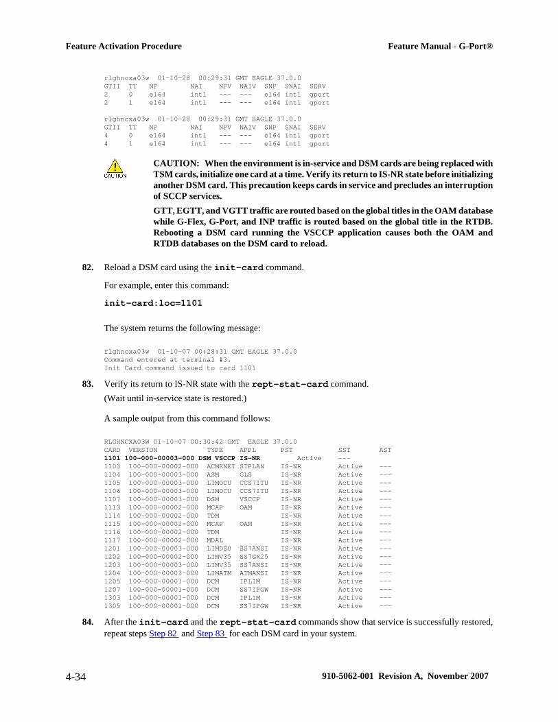
rlghncxa03w 01-10-28 00:29:31 GMT EAGLE 37.0.0GTII TT NP NAI NPV NAIV SNP SNAI SERV2 0 e164 intl --- --- e164 intl gport 2 1 e164 intl --- --- e164 intl gport
rlghncxa03w 01-10-28 00:29:31 GMT EAGLE 37.0.0GTII TT NP NAI NPV NAIV SNP SNAI SERV 4 0 e164 intl --- --- e164 intl gport 4 1 e164 intl --- --- e164 intl gport
CAUTION: When the environment is in-service and DSM cards are being replaced withTSM cards, initialize one card at a time. Verify its return to IS-NR state before initializinganother DSM card. This precaution keeps cards in service and precludes an interruptionof SCCP services.GTT, EGTT, and VGTT traffic are routed based on the global titles in the OAM databasewhile G-Flex, G-Port, and INP traffic is routed based on the global title in the RTDB.Rebooting a DSM card running the VSCCP application causes both the OAM andRTDB databases on the DSM card to reload.
82. Reload a DSM card using the init-card command.
For example, enter this command:
init-card:loc=1101
The system returns the following message:
rlghncxa03w 01-10-07 00:28:31 GMT EAGLE 37.0.0Command entered at terminal #3. Init Card command issued to card 1101
83. Verify its return to IS-NR state with the rept-stat-card command.(Wait until in-service state is restored.)
A sample output from this command follows:
RLGHNCXA03W 01-10-07 00:30:42 GMT EAGLE 37.0.0CARD VERSION TYPE APPL PST SST AST1101 100-000-00003-000 DSM VSCCP IS-NR Active ---1103 100-000-00002-000 ACMENET STPLAN IS-NR Active ---1104 100-000-00003-000 ASM GLS IS-NR Active ---1105 100-000-00003-000 LIMOCU CCS7ITU IS-NR Active ---1106 100-000-00003-000 LIMOCU CCS7ITU IS-NR Active ---1107 100-000-00003-000 DSM VSCCP IS-NR Active ---1113 100-000-00002-000 MCAP OAM IS-NR Active ---1114 100-000-00002-000 TDM IS-NR Active ---1115 100-000-00002-000 MCAP OAM IS-NR Active ---1116 100-000-00002-000 TDM IS-NR Active ---1117 100-000-00002-000 MDAL IS-NR Active ---1201 100-000-00003-000 LIMDS0 SS7ANSI IS-NR Active ---1202 100-000-00002-000 LIMV35 SS7GX25 IS-NR Active ---1203 100-000-00003-000 LIMV35 SS7ANSI IS-NR Active ---1204 100-000-00003-000 LIMATM ATMANSI IS-NR Active ---1205 100-000-00001-000 DCM IPLIM IS-NR Active ---1207 100-000-00001-000 DCM SS7IPGW IS-NR Active ---1303 100-000-00001-000 DCM IPLIM IS-NR Active ---1305 100-000-00001-000 DCM SS7IPGW IS-NR Active ---
84. After the init-card and the rept-stat-card commands show that service is successfully restored,repeat steps Step 82 and Step 83 for each DSM card in your system.
Feature Activation Procedure Feature Manual - G-Port®
4-34 910-5062-001 Revision A, November 2007
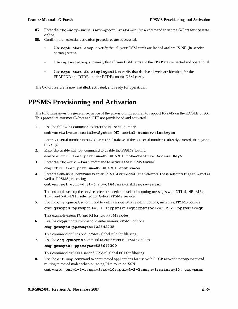
85. Enter the chg-sccp-serv:serv=gport:state=online command to set the G-Port service stateonline.
86. Confirm that essential activation procedures are successful.
• Use rept-stat-sccp to verify that all your DSM cards are loaded and are IS-NR (in-servicenormal) status.
• Use rept-stat-mps to verify that all your DSM cards and the EPAP are connected and operational.
• Use rept-stat-db:display=all to verify that database levels are identical for theEPAPPDB and RTDB and the RTDBs on the DSM cards.
The G-Port feature is now installed, activated, and ready for operations.
PPSMS Provisioning and ActivationThe following gives the general sequence of the provisioning required to support PPSMS on the EAGLE 5 ISS.This procedure assumes G-Port and GTT are provisioned and activated.
1. Use the following command to enter the NT serial number.ent-serial-num:serial=<System NT serial number>:lock=yesEnter NT serial number into EAGLE 5 ISS database. If the NT serial number is already entered, then ignorethis step.
2. Enter the enable-ctrl-feat command to enable the PPSMS feature.enable-ctrl-feat:partnum=893006701:fak=<Feature Access Key>
3. Enter the chg-ctrl-feat command to activate the PPSMS feature.chg-ctrl-feat:partnum=893006701:status=on
4. Enter the ent-srvsel command to enter GSMG-Port Global Title Selectors These selectors trigger G-Port aswell as PPSMS processing.ent-srvsel:gtii=4:tt=0:np=e164:nai=intl:serv=smsmrThis example sets up the service selectors needed to select incoming messages with GTI=4, NP=E164,TT=0 and NAI=INTL selected for G-Port/PPSMS service.
5. Use the chg-gsmopts command to enter various GSM system options, including PPSMS options.chg-gsmopts:ppsmspci1=1-1-1:ppsmsri1=gt:ppsmspci2=2-2-2: ppsmsri2=gtThis example enters PC and RI for two PPSMS nodes.
6. Use the chg-gsmopts command to enter various PPSMS options.chg-gsmopts:ppsmsgta=123543235This command defines one PPSMS global title for filtering.
7. Use the chg-gsmopts command to enter various PPSMS options.chg-gsmopts: ppsmsgta=555648309This command defines a second PPSMS global title for filtering.
8. Use the ent-map command to enter mated applications for use with SCCP network management androuting to mated nodes when outgoing RI = route-on-SSN.ent-map: pci=1-1-1:ssn=8:rc=10:mpci=3-3-3:mssn=8:materc=10: grp=smsc
Feature Manual - G-Port® PPSMS Provisioning and Activation
910-5062-001 Revision A, November 2007 4-35

Enters PPSMSPC 1-1-1 and node PC 3-3-3 as load shared mates. This entry is only used if the PPSMSRI isequal to the SSN in the GSMOPTS table. This is not the case for PPSMSPC1 in this example.
9. Use the ent-mrn command to enter mated relay nodes for routing to mated node when outgoing RI=route-on-GT.ent-mrn:pci=2-2-2:rc=10:pci1=3-3-3:rc1=10Enters PPSMSPC 2-2-2 and node PC 3-3-3 as load shared mates. This entry is only used if the PPSMSRI isequal to the GT in the GSMOPTS table, which it is in this case for PPSMSPC2.
ISUP NP with EPAP Provisioning and ActivationThis section presents the general sequence of the provisioning required to support ISUPNP with EPAP on theEAGLE 5 ISS. This procedure assumes G-Port, GWS, and GTT are provisioned and activated. Table 4-1 andTable 4-2 are included with example provisioning data used in the provisioning and activation procedure.
Table 4-1. SubNet Prefix Table Example
SubNet No. SubNet Prefix
1 1001
2 1002
3 1003
4 1004
5 1005
Table 4-2. SubNet ID List Example
SubNet ID SubNet No.
886932 1
886935 2
886936 3
886938 4
886939 5
886940 5
886941 1
• SubNet No. - A subset of an the network. The network may consist of 1 or more Subnets in the network.
• SubNet ID - The SubNet Id refers to the network entity address of the HLR within the operator's network.
• SubNet Prefix - The SubNet Prefix is defined as a provisionable number that is prepended to the Called PartyNumber of an IAM message.
ISUP NP with EPAP Provisioning and Activation Feature Manual - G-Port®
4-36 910-5062-001 Revision A, November 2007

The general sequence of the provisioning required to support ISUPNP with EPAP on the EAGLE 5 ISS is presentedbelow.
1. Use the following command to enter the NT serial number.ent-serial-num:serial=<System NT serial number>:lock=yesEnter NT serial number into EAGLE 5 ISS database. If the NT serial number is already entered, then ignorethis step.
2. Enter the enable-ctrl-feat command to enable the ISUPNP with EPAP feature.enable-ctrl-feat:partnum=893013801:fak=<Feature Access Key>
3. Enter the chg-prefix-feat command to relate the ISUPNP with EPAP feature to a prefix, and to specifyan prefix ID number that is used to refer to the prefix value from another table.Examples of the use of this command follow:
chg-prefix:feature="isup np with epap"prefixnum=1:prefix=1001chg-prefix:feature="isup np with epap"prefixnum=2:prefix=1002chg-prefix:feature="isup np with epap"prefixnum=3:prefix=1003chg-prefix:feature="isup np with epap"prefixnum=4:prefix=1004chg-prefix:feature="isup np with epap"prefixnum=5:prefix=1005
4. Enter the following command to determine the allowed length for the subnetid values.ent-subnetid:subnetidlen=6
5. Enter the following command to associate the subnetid with a subnet number.ent-subnetid:subnetid=886932:subnetnum=1ent-subnetid:subnetid=886935:subnetnum=2ent-subnetid:subnetid=886936:subnetnum=3ent-subnetid:subnetid=886938:subnetnum=4ent-subnetid:subnetid=886940:subnetnum=5
6. The EPAP database must be populated for the ported suscribers.Refer to the Provisioning Database Interface Manual to add and update the Network Entity and DialedNumber data for ported subscribers and subscribers belonging to the subnet.
7. Enter the commands related to Gateway Screening to add the STOPACTIONTLNP for the requiredcombination of the screening rules for the OPC, DPC, SIO , ISUP, and message type=IAM. For more detailsabout gateway screening commands, refer to the Database Administration Manual-Gateway Screening.The gateway screening commands include the following.
a. Command(s) to configure the gateway screening stop action sets in the system database.chg-gws-actset:actid=4:actname=fet:act1=tlnp
b. Command(s) to add an allowed ISUP screening reference to the Allowed ISUP entity set.One or more message types can be associated with the allowed ISUP screening reference. The ISUPmessage types listed in this entity set are accepted from another network.
ent-scr-isup:sr=is1:isupmt=1:nsfi=STOP:actname=fet
c. Command(s) to allow all other types of ISUP messages for normal processing.ent-scr-dpc:sr=dpc1:zone=2:area=102:id=1:nsfi=isup:nsr=is1
d. Command(s) to allow all other DPCs of the route table for normal processing.
Feature Manual - G-Port® ISUP NP with EPAP Provisioning and Activation
910-5062-001 Revision A, November 2007 4-37

As a rule, every DPC in the Route table must be explicitly provisioned.
ent-scr-sio:sr=sio1:nic=0:pri=0:si=5:NSFI=DPC:nsr=dpc1
e. Command(s) to allow all other SIO for the normal processing.ent-scr-opc:sr=opc1:zone=2:area=101:id=1:nsfi=sio :nsr=sio1
f. Command(s) to allow all other OPC for normal processingent-scrset:scrn=f1:NSFI=OPC:nsr=opc1chg-ls:lsn=srcmgt:scrn=f1:gwsa=on
8. Enter the chg-ctrl-feat command to activate the ISUPNP with EPAP feature.chg-ctrl-feat:partnum=893013801:status=ON
The 1100 TPS/DMS for ITU NP FeatureThis procedure is used to enable and turn on the 1100 TPS/DSM for ITU NP feature. This feature provides up to26,400 transactions per second when the maximum number of DSM cards are installed in the EAGLE 5 ISS andone or more EPAP-related features (such as G-Port, G-Flex, A-Port, INP, EIR, Migration) are enabled and turnedon.
This feature can be enabled only for DSMs that are rated at 850 transactions per second (TPS).
CAUTION: The increase of the DSM capacity, 1100 TPS per DSM, assumes incoming trafficconsists of at least 30% of GTT routed traffic that does not require EPAP based lookup. Ifmore than 70% of incoming traffic requires EPAP based lookup, Group Ticket Voucher (TVG)may shutdown and overall TVG capacity of 1100 for the card may not be met.
The feature access key is based on the feature’s part number and the serial number of the EAGLE 5 ISS, makingthe feature access key site-specific.
The enable-ctrl-feat command enables the 1100 TPS/DSM for ITU NP feature by inputting the feature’saccess key and the feature’s part number with these parameters:
:fakThe feature access key provided by Tekelec. The feature access key contains 13 alphanumeric characters andis not case sensitive.
:partnumThe Tekelec-issued part number of the 1100 TPS/DSM for ITU NP feature, 893018001.
After the 1100 TPS/DSM for ITU NP feature has been enabled, the feature must be turned on with the chg-ctrl-feat command. The chg-ctrl-feat command uses these parameters::partnum
The Tekelec-issued part number of the 1100 TPS/DSM or ITU NP feature, 893019101.:status=on
Used to turn the 1100 TPS/DSM for ITU NP feature on.
Activating the 1100 TPS/DSM for ITU NP Feature
Before you start: The 1100 TPS/DSM for ITU NP feature cannot be enabled with a temporary feature access key.
The 1100 TPS/DSM for ITU NP feature cannot be enabled if:
The 1100 TPS/DMS for ITU NP Feature Feature Manual - G-Port®
4-38 910-5062-001 Revision A, November 2007

• The EAGLE 5 ISS does not contain any DSM cards.
• The LNP feature is enabled.
The status of the LNP feature is shown with the rtrv-ctrl-feat command output.
• The ANSI G-Flex STP Option is enabled.
The status of the ANSI G-Flex STP Option is shown in the rtrv-stpopts command output.
• The GTT feature is not turned on.
The status of the GTT feature is shown in the rtrv-feat command output.
The enable-ctrl-feat command requires that the database contain a valid serial number for the EAGLE 5ISS, and that this serial number is locked. This can be verified with the rtrv-serial-num command. TheEAGLE 5 ISS is shipped with a serial number in the database, but the serial number is not locked. The serialnumber can be changed, if necessary, and locked once the EAGLE 5 ISS is on-site, with the ent-serial-num command. The ent-serial-num command uses these parameters.:serial
The serial number assigned to the EAGLE 5 ISS. The serial number is not case sensitive.:lock
Specifies whether or not the serial number is locked. This parameter has only one value, yes, which locks theserial number. Once the serial number is locked, it cannot be changed.
NOTE: To enter and lock the EAGLE 5 ISS’s serial number, the ent-serial-num command must beentered twice, once to add the correct serial number to the database with the serial parameter, then againwith the serial and the lock=yes parameters to lock the serial number. Verify that the serial numberin the database is correct before locking the serial number. The serial number can be found on a label affixedto the control shelf (shelf 1100).
The 1100 TPS/DSM for ITU NP feature increases the processing capacity of SCCP traffic for an EAGLE 5 ISSprocessing EPAP-based traffic to 26,400 transactions per second. To achieve this increase in SCCP processingcapacity, a maximum of 25 DSM cards must be provisioned and installed in the EAGLE 5 ISS.
1. Display the status of the 1100 TPS/DSM feature by entering the rtrv-ctrl-feat command.
The following is an example of the possible output:rlghncxa03w 07-05-28 21:15:37 GMT EAGLE5 37.5.0
The following features have been permanently enabled: Feature Name Partnum Status Quantity TPS 893000110 on 1000 ISUP Normalization 893000201 on ---- Prepaid SMS Intercept Ph1 893006701 on ---- MNP Circ Route Prevent 893007001 on ---- 1100 TPS/DSM for ITU NP 893018001 on ----
The following features have been temporarily enabled: Feature Name Partnum Status Quantity Trial Period Left TPS 893000140 on 4000 20 days 8 hrs 57 mins
The following features have expired temporary keys: Feature Name Part Num OnOffFeatV 893492401
2. Based on the output from the previous step, do one of the following:
Feature Manual - G-Port® The 1100 TPS/DMS for ITU NP Feature
910-5062-001 Revision A, November 2007 4-39

• If the rtrv-ctrl-feat output shows that the 1100 TPS/DSM for ITU NP feature is enabled, shownby the entry 1100 TPS/DSM for ITU NP, and its status is on, no further action is necessary.
• If the feature is enabled, and its status is off, skip Step 3 through Step 12 , and go to Step 13 .
• If the rtrv-ctrl-feat output shows that the LNP feature is enabled, this procedure cannot be performed.The 1100 TPS/DSM for ITU NP feature cannot be enabled if the LNP feature is enabled.
• If the 1100 TPS/DSM for ITU NP and LNP features are not enabled, go to Step 3 .
3. Determine whether the G-Flex feature is turned on by entering the rtrv-feat.
(If the G-Flex feature is off, then the ANSIGFLEX option is not displayed in the rtrv-stpopts outputin Step 4 .)
The G-Flex feature is shown by the entry G-Flex in the rtrv-feat output.
• If the G-Flex feature is turned off, skip to Step 5 .
• If the G-Flex feature is turned on, go to Step 4 .
4. Verify that the ANSI G-Flex option is not enabled or turned on by entering the rtrv-stpopts command.
The 1100 TPS/DSM ITU NP feature cannot be enabled if the ANSI G-Flex option is turned on.
The ANSI G-Flex option is shown by the entry ANSIGFLEX in the rtrv-stpopts output. If theANSIGFLEXentry is displayed in the rtrv-stpopts output, both the G-Flex and the GTT features areturned on.
• If the ANSIGFLEX value is yes, the ANSI G-Flex option is enabled and this procedure cannot beperformed.
• If the ANSIGFLEX value is no, the ANSI G-Flex option is not enabled. Skip Step 5 and go to Step6 .
5. Determine whether the GTT feature is turned on by examining the output of the rtrv-ctrl-featcommand.
The 1100 TPS/DSM ITU NP feature cannot be enabled unless the GTT feature is turned on. The GTT featureis shown by the entry GTT in the rtrv-feat output executed in Step 3 .
• If the GTT feature is turned on, go to Step 6 .
• If the GTT feature is turned off, perform the ”Adding an SCCP card” in the Database AdministrationManual - Global Title Translation to turn the GTT feature on and to add the required number of DSMcards to the database. After the ”Adding an SCCP card” has been performed, skip Step 6 throughStep 10 , and go to Step 11 .
6. Verify the number of DSM cards that are provisioned in the database using the rept-stat-gpl:gpl=sccphc command.
This is an example of the possible output.rlghncxa03w 07-05-01 11:40:26 GMT EAGLE5 37.5.0 GPL CARD RUNNING APPROVED TRIAL VSCCCP 1201 126-002-000 126-002-000 126-003-000 VSCCCP 1203 126-002-000 126-002-000 126-003-000 VSCCCP 1207 126-002-000 126-002-000 126-003-000 VSCCCP 1213 126-002-000 126-002-000 126-003-000 VSCCCP 1215 126-002-000 126-002-000 126-003-000 VSCCCP 1305 126-002-000 126-002-000 126-003-000 VSCCCP 1313 126-002-000 126-002-000 126-003-000
The 1100 TPS/DMS for ITU NP Feature Feature Manual - G-Port®
4-40 910-5062-001 Revision A, November 2007
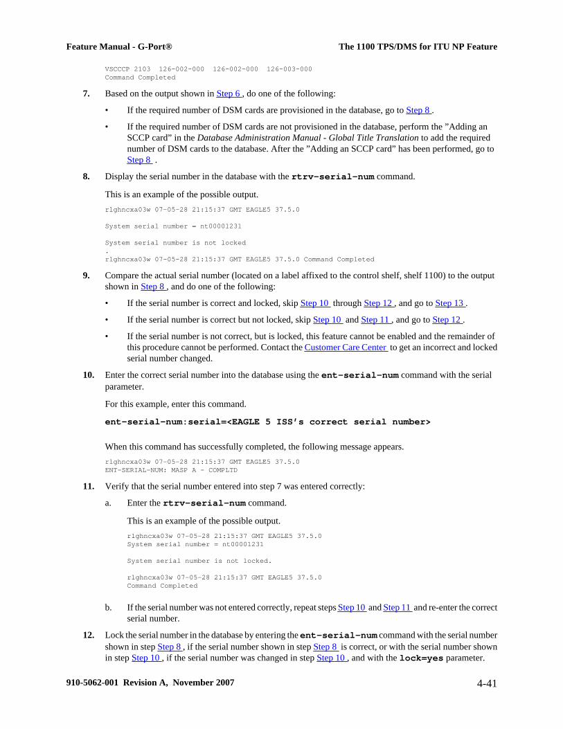
VSCCCP 2103 126-002-000 126-002-000 126-003-000 Command Completed
7. Based on the output shown in Step 6 , do one of the following:
• If the required number of DSM cards are provisioned in the database, go to Step 8 .
• If the required number of DSM cards are not provisioned in the database, perform the ”Adding anSCCP card” in the Database Administration Manual - Global Title Translation to add the requirednumber of DSM cards to the database. After the ”Adding an SCCP card” has been performed, go toStep 8 .
8. Display the serial number in the database with the rtrv-serial-num command.
This is an example of the possible output.rlghncxa03w 07-05-28 21:15:37 GMT EAGLE5 37.5.0 System serial number = nt00001231 System serial number is not locked. rlghncxa03w 07-05-28 21:15:37 GMT EAGLE5 37.5.0 Command Completed
9. Compare the actual serial number (located on a label affixed to the control shelf, shelf 1100) to the outputshown in Step 8 , and do one of the following:
• If the serial number is correct and locked, skip Step 10 through Step 12 , and go to Step 13 .
• If the serial number is correct but not locked, skip Step 10 and Step 11 , and go to Step 12 .
• If the serial number is not correct, but is locked, this feature cannot be enabled and the remainder ofthis procedure cannot be performed. Contact the Customer Care Center to get an incorrect and lockedserial number changed.
10. Enter the correct serial number into the database using the ent-serial-num command with the serialparameter.
For this example, enter this command.
ent-serial-num:serial=<EAGLE 5 ISS’s correct serial number>
When this command has successfully completed, the following message appears.rlghncxa03w 07-05-28 21:15:37 GMT EAGLE5 37.5.0 ENT-SERIAL-NUM: MASP A - COMPLTD
11. Verify that the serial number entered into step 7 was entered correctly:
a. Enter the rtrv-serial-num command.
This is an example of the possible output.rlghncxa03w 07-05-28 21:15:37 GMT EAGLE5 37.5.0System serial number = nt00001231
System serial number is not locked.
rlghncxa03w 07-05-28 21:15:37 GMT EAGLE5 37.5.0 Command Completed
b. If the serial number was not entered correctly, repeat steps Step 10 and Step 11 and re-enter the correctserial number.
12. Lock the serial number in the database by entering the ent-serial-num command with the serial numbershown in step Step 8 , if the serial number shown in step Step 8 is correct, or with the serial number shownin step Step 10 , if the serial number was changed in step Step 10 , and with the lock=yes parameter.
Feature Manual - G-Port® The 1100 TPS/DMS for ITU NP Feature
910-5062-001 Revision A, November 2007 4-41

For this example, enter this command.
ent-serial-num:serial=<EAGLE 5 ISS’s serial number>:lock=yes
When this command has successfully completed, the following message should appear.rlghncxa03w 07-05-28 21:15:37 GMT EAGLE5 37.5.0 ENT-SERIAL-NUM: MASP A - COMPLTD
13. Enable the 1100 TPS/DSM for ITU NP feature with the permanent key by entering the enable-ctrl-feat command.
For this example, enter this command.
enable-ctrl-feat:partnum=893018001:fak=<1100 TPS/DSM for ITU NP featureaccess key>
NOTE: The values for the feature access key (the fak parameter) are provided by Tekelec. If you donot have the feature access key for the 1100 TPS/DSM for ITU NP feature, contact your Tekelec SalesRepresentative or Account Representative.
When the enable-crtl-feat command has successfully completed, this message should appear.rlghncxa03w 07-05-28 21:15:37 GMT EAGLE5 37.5.0 ENABLE-CTRL-FEAT: MASP B - COMPLTD
14. Do one of the following:
• If you do not wish to turn the 1100 TPS/DSM for ITU NP feature on, skip this step and go to step Step16 . If you do not turn this feature on, the transaction rate will remain at 850 TPS/DSM.
• If you do wish to turn on the 1100 TPS/DSM for ITU NP feature, enter he chg-ctrl-feat command,specifying the 1100 TPS/DSM for ITU NP feature part number used in step Step 13 and thestatus=on parameter and enter the command again as shown in step Step 15 .
For this example, enter this command:
chg-ctrl-feat:partnum=893018001:status=on
The following output message appears:CAUTION: Rated TPS for this feature supports an engineered GTT traffic mix of no more than 70 percent EPAP-based traffic. Re-enter the command within 30 seconds to confirm change.
CAUTION: If the EPAP-based traffic is higher than 70% of all traffic on the EAGLE5ISS, the DSM cards performance may not reach 1100 TPS per DSM.
15. Reenter the chg-ctrl-feat command to turn the feature ON.chg-ctrl-feat:partnum=893018001:status=on
When this command has successfully completed, the following message should appear:rlghncxa03w 07-05-28 21:15:37 GMT EAGLE5 37.5.0 CHG-CTRL-FEAT: MASP B - COMPLTD
16. Verify the changes by entering the rtrv-ctrl-feat command with the 1100 TPS/DSM for ITU NPfeature part number specified in steps Step 14 or Step 15 .rtrv-ctrl-feat:partnum=893018001
The following is an example of the possible output.
The 1100 TPS/DMS for ITU NP Feature Feature Manual - G-Port®
4-42 910-5062-001 Revision A, November 2007

rlghncxa03w 07-05-28 21:15:37 GMT EAGLE5 37.5.0 The following features have been permanently enabled: Feature Name Partnum Status Quantity TPS 893000110 on 1000 ISUP Normalization 893000201 on ---- Prepaid SMS Intercept Ph1 893006701 on ---- MNP Circ Route Prevent 893007001 on ---- 1100 TPS/DSM for ITU NP 893018001 on ----
The following features have been temporarily enabled: Feature Name Partnum Status Quantity Trial Period Left TPS 893000140 on 4000 20 days 8 hrs 57 mins
The following features have expired temporary keys: Feature Name Part Num OnOffFeatV 893492401
17. Backup the new changes by entering:
chg-db:action=backup:dest=fixed
These messages should appear, the active Maintenance and Administration Subsystem Processor (MASP)appears first.BACKUP (FIXED) : MASP A - Backup starts on active MASP. BACKUP (FIXED) : MASP A - Backup on active MASP to fixed disk complete. BACKUP (FIXED) : MASP A - Backup starts on standby MASP. BACKUP (FIXED) : MASP A - Backup on standby MASP to fixed disk complete.
18. If you wish to turn off TPS/DSM for ITU NP feature, enter the chg-ctrl-feat command, specifyingthe 1100 TPS/DSM feature part number used in step Step 14 and the status=off parameter.
For this example, enter this command.
chg-ctrl-feat:partnum=893018001:status=off
The following output message appears:CAUTION: This command decreases the total TPS of the SCCP system from 1100 to 850 TPS for each DSM card.
19. Confirm that you wish to turn off TPS/DSM for ITU NP feature by re-entering the command, as shownbelow, within 30 seconds:
chg-ctrl-feat:partnum=893018001:status=off
When this command has successfully completed, the following message should appear.rlghncxa03w 07-05-28 21:15:37 GMT EAGLE5 37.5.0 CHG-CTRL-FEAT: MASP B - COMPLTD
Activating the E5-SM4G Throughput Capacity FeatureThis procedure is used to enable and turn on the E5-SM4G Throughput Capacity feature. This feature provides upto 75,000 transactions per second when the maximum nuber of E5-SM4G cards are installed in the EAGLE 5 ISSand one or more EPAP-related features (such as G-Port, A-Port, G-Flex) are enabled and turned on.
The feature access key is based on the feature's part number and the serial number of the EAGLE 5 ISS, makingthe feature access key site-specific.The enable-ctrl-feat command enables the E5-SM4G Throughput Capacity feature by inputting thefeature's access key and the feature's part number with these parameters:
Feature Manual - G-Port® Activating the E5-SM4G Throughput Capacity Feature
910-5062-001 Revision A, November 2007 4-43

:fakThe feature access key provided by Tekelec. The feature access key contains 13 alphanumeric characters andis not case sensitive.
:partnumThe Tekelec-issued part number of the E5-SM4G Throughput Capacity feature, 893019101.
This feature cannot be enabled with a temporary feature access key.
The E5-SM4G Throughput Capacity feature cannot be enabled if:
• The LNP feature is enabled.
• The STPLAN feature is turned on.
• The GTT feature is not turned on.
The E5-SM4G Throughput Capacity feature cannot be enabled unless the EAGLE 5 ISS contains E5-SM4G cards,and E5-SM4G cards cannot be installed in the EAGLE 5 ISS unless HIPR cards are installed in all shelvescontaining E5-SM4G cards. Enter the rept-stat-gpl:gpl=hipr command to verify if HIPR cards areinstalled in all shelves containing E5-SM4G cards.
The status of the LNP feature is shown with the rtrv-ctrl-feat command output.
The status of the GTT is shown in the rtrv-feat command output.
The enable-ctrl-feat command requires that the database contain a valid serial number for the EAGLE 5ISS, and that this serial number is locked. This can be verified with the rtrv-serial-num command. TheEAGLE 5 ISS is shipped with a serial number in the database, but the serial number is not locked. The serialnumber can be changed, if necessary, and locked once the EAGLE 5 ISS is on-site, with the ent-serial-num command. The ent-serial-num command uses these parameters.:serial
The serial number assigned to the EAGLE 5 ISS. The serial number is not case sensitive.:lock
Specifies whether or not the serial number is locked. This parameter has only one value, yes, which locks theserial number. Once the serial number is locked, it cannot be changed.
NOTE: To enter and lock the EAGLE 5 ISS's serial number, the ent-serial-num command must beentered twice, once to add the correct serial number to the database with the serial parameter, then againwith the serial and the lock=yes parameters to lock the serial number. Before locking the serial number,insure that the serial number in the database is correct. The serial number can be found on a label affixedto the control shelf (shelf 1100).
Once the E5-SM4G Throughput Capacity feature has been enabled, the feature must be turned on with the chg-ctrl-feat command. The chg-ctrl-feat command uses these parameters:
:partnumThe Tekelec-issued part number of the E5-SM4G Throughput Capacity feature, 893019101
:status=onused to turn the E5-SM4G Throughput Capacity feature on.
This feature increases the processing capacity of SCCP traffic for an EAGLE 5 ISS processing EPAP-based trafficto 75,000 transactions per second. To achieve this increase in SCCP processing capacity, a maximum of 25 E5-SM4G cards must be provisioned and installed in the EAGLE 5 ISS.
1. Display the status of the E5-SM4G Throughput Capacity feature by entering the rtrv-ctrl-featcommand.
Activating the E5-SM4G Throughput Capacity Feature Feature Manual - G-Port®
4-44 910-5062-001 Revision A, November 2007

Possible output of this command follows:rlghncxa03w 07-05-28 21:15:37 GMT EAGLE5 37.0.0The following features have been permanently enabled:
Feature Name Partnum Status QuantityIPGWx Signaling TPS 893012814 on 20000ISUP Normalization 893000201 on ----Command Class Management 893005801 on ----Intermed GTT Load Sharing 893006901 off ----XGTT Table Expansion 893006101 off ----XMAP Table Expansion 893007710 on 3000Large System # Links 893005910 on 2000Routesets 893006401 on 6000HC-MIM SLK Capacity 893012707 on 64
The following features have been temporarily enabled:
Feature Name Partnum Status Quantity Trial Period LeftZero entries found.
The following features have expired temporary keys:
Feature Name PartnumZero entries found.MNP Circ Route Prevent 893007001 On ---- 20 days 8 hrs 57 mins
If the rtrv-ctrl-feat output shows that the E5-SM4G Throughput Capacity feature is enabled, shownby the entry E5-SM4G Throughput Cap, and its status is on, no further action is necessary.
If the feature is enabled, and its status is off, skip Step 2 through Step 7 , and go to Step 8 .
If the rtrv-ctrl-feat output shows that the LNP feature is enabled, this procedure cannot be performed.The E5-SM4G Throughput Capacity feature cannot be enabled if the LNP feature is enabled.
If the E5-SM4G Throughput Capacity and LNP features are not enabled, go to Step 2 .
2. Enter the rtrv-feat command to verify the status of the STPLAN feature.
To enable the E5-SM4G Throughput Capacity feature, the STPLAN feature cannot be turned on.
The STPLAN feature is shown by the entry LAN in the rtrv-feat output.
If the STPLAN feature is turned on, this procedure cannot be performed.
If the STPLAN feature is turned off, go to Step 3
3. Verify that the GTT feature is turned on.
To enable the E5-SM4G Throughput Capacity feature, the GTT feature must be turned on. The GTT featureis shown by the entry GTT in the rtrv-feat output executed in Step 2 . If the GTT feature is turned on, go toStep 4 . If the GTT feature is turned off, perform the "Adding an SCCP card" in the Database AdministrationManual - Global Title Translation to:
• Turn the GTT feature
• add the required number of E5-SM4G cards to the database
After the "Adding an SCCP card" has been performed, skip Step 4 , and go to Step 5 .
4. Verify the number of E5-SM4G cards that are provisioned in the database using the rept-stat-gpl:gpl=sccphc command.
This is an example of the possible output.rlghncxa03w 07-05-01 11:40:26 GMT EAGLE5 37.0.0GPL CARD RUNNING APPROVED TRIALSCCPHC 1201 126-002-000 126-002-000 126-003-000SCCPHC 1203 126-002-000 126-002-000 126-003-000
Feature Manual - G-Port® Activating the E5-SM4G Throughput Capacity Feature
910-5062-001 Revision A, November 2007 4-45

SCCPHC 1207 126-002-000 126-002-000 126-003-000SCCPHC 1213 126-002-000 126-002-000 126-003-000SCCPHC 1215 126-002-000 126-002-000 126-003-000SCCPHC 1305 126-002-000 126-002-000 126-003-000SCCPHC 1313 126-002-000 126-002-000 126-003-000SCCPHC 2103 126-002-000 126-002-000 126-003-000Command Completed
If the required number of E5-SM4G cards are provisioned in the database, go to Step 5 .
If the required number of E5-SM4G cards are not provisioned in the database, perform the "Adding an SCCPcard" in the Database Administration Manual - Global Title Translation to add the required number of E5-SM4G cards to the database. After the "Adding an SCCP card" has been performed, go to Step 5 .
5. Verify whether HIPR cards are installed on all the EAGLE 5 ISS shelves containing E5-SM4G cards usingthe rept-stat-gpl:gpl=hipr command.the rept-stat-gpl:gpl=hipr command.rlghncxa03w 07-05-01 11:40:26 GMT EAGLE5 37.0.0GPL CARD RUNNING APPROVED TRIALHIPR 1109 126-002-000 126-002-000 126-003-000HIPR 1110 126-002-000 126-002-000 126-003-000HIPR 1209 126-002-000 126-002-000 126-003-000HIPR 1210 126-002-000 126-002-000 126-003-000HIPR 1309 126-002-000 126-002-000 126-003-000HIPR 1310 126-002-000 126-002-000 126-003-000HIPR 2109 126-002-000 126-002-000 126-003-000HIPR 2110 126-002-000 126-002-000 126-003-000Command Completed
If HIPR cards are installed in all shelves containing E5-SM4G cards , go to Step 6
If HIPR cards are not installed on all shelves containing E5-SM4G cards, refer to the Installation Manual -EAGLE 5 ISS and install the HIPR cards. Once the HIPR cards have been installed, go to Step 6 .
6. Display the serial number in the database with the rtrv-serial-num command.
An example of output from this command follows:rlghncxa03w 07-05-28 21:15:37 GMT EAGLE5 37.0.0System serial number = nt00001231
System serial number is not locked.
rlghncxa03w 07-05-28 21:15:37 GMT EAGLE5 37.0.0Command Completed
If the serial number is correct and locked, skip Step 7 , Step 8 , and Step 9 , and go to Step 10 . If the serialnumber is correct but not locked, skip skip Step 7 and Step 8 , and go to Step 9 . If the serial number is notcorrect, but is locked, this feature cannot be enabled and the remainder of this procedure cannot be performed.Contact the Customer Care Center to get an incorrect and locked serial number changed. Refer to CustomerCare Center for the contact information. The serial number can be found on a label affixed to the controlshelf (shelf 1100)
7. Enter the correct serial number into the database using the ent-serial-num command with the serialparameter .
For this example, enter this command:
ent-serial-num:serial=<EAGLE 5 ISS's correct serial number>When this command has successfully completed, the following message appears.rlghncxa03w 07-05-28 21:15:37 GMT EAGLE5 37.0.0ENT-SERIAL-NUM: MASP A - COMPLTD
Activating the E5-SM4G Throughput Capacity Feature Feature Manual - G-Port®
4-46 910-5062-001 Revision A, November 2007

8. Verify that the serial number entered into Step 7 was entered correctly using the rtrv-serial-numcommand.
An example of output from this command follows:rlghncxa03w 07-05-28 21:15:37 GMT EAGLE5 37.0.0System serial number = nt00001231
System serial number is not locked.
rlghncxa03w 07-05-28 21:15:37 GMT EAGLE5 37.0.0Command Completed
If the serial number was not entered correctly, repeat Step 7 and Step 8 and re-enter the correct serialnumber.
9. Lock the serial number in the database by entering the ent-serial-num command with the serial numbershown in Step 6 , if the serial number shown in Step 6 is correct, or with the serial number shown in Step8 , if the serial number was changed in Step 7 , and with the lock=yes parameter.
For this example, enter this command:
ent-serial-num:serial=<EAGLE 5 ISS's serial number>:lock=yesWhen this command has successfully completed, the following message appears:rlghncxa03w 07-05-28 21:15:37 GMT EAGLE5 37.0.0ENT-SERIAL-NUM: MASP A - COMPLTD
10. Enable the E5-SM4G Throughput Capacity feature with the permanent key by entering the enable-ctrl-feat command.
For this example, enter the following command:
enable-ctrl-feat:partnum=893019101:fak=<E5-SM4G Throughput Capacityfeature access key>NOTE: The values for the feature access key (the fak parameter) are provided by Tekelec. If thefeature access key for the E5-SM4G Throughput Capacity feature is not known, contact your TekelecSales Representative or Account Representative.
When the enable-crtl-feat command has successfully completed, this message appears:rlghncxa03w 07-05-28 21:15:37 GMT EAGLE5 37.0.0ENABLE-CTRL-FEAT: MASP B - COMPLTD
Note: If you do not wish to turn the E5-SM4G Throughput Capacity feature on, skip Step 11 and go to Step12 .
11. Turn the E5-SM4G Throughput Capacity feature using the chg-ctrl-feat command, specifying theE5-SM4G Throughput Capacity feature part number used in Step 10 and the status=on parameter.
For example, enter the following command:
chg-ctrl-feat:partnum=893019101:status=onNOTE: Once this feature is turned on, it cannot be turned off.
When this command has successfully completed, the following message appears:rlghncxa03w 07-05-28 21:15:37 GMT EAGLE5 37.0.0CHG-CTRL-FEAT: MASP B - COMPLTD
12. Verify the changes by entering the rtrv-ctrl-feat command with the E5-SM4G Throughput Capacity featurepart number specified inStep 10 or Step 11 .
For example, enter the following command:
Feature Manual - G-Port® Activating the E5-SM4G Throughput Capacity Feature
910-5062-001 Revision A, November 2007 4-47

rtrv-ctrl-feat:partnum=893019101An example of output from this command follows:rlghncxa03w 07-05-28 21:15:37 GMT EAGLE5 37.0.0The following features have been permanently enabled:
Feature Name Partnum Status QuantityE5-SM4G Throughput Cap 893019101 on ----
The following features have been temporarily enabled:
Feature Name Partnum Status Quantity Trial Period LeftZero entries found.G-Port Circ Route Prevent 893007001 On ---- 20 days 8 hrs 57 mins
The following features have expired temporary keys:Feature Name PartnumZero entries found.
13. Backup the new changes using the chg-db:action=backup:dest=fixed command.
The following messages appear, with the active Maintenance and Administration Subsystem Processor(MASP) appearing first, as shown.BACKUP (FIXED) : MASP A - Backup starts on active MASP.BACKUP (FIXED) : MASP A - Backup on active MASP to fixed disk complete.BACKUP (FIXED) : MASP A - Backup starts on standby MASP.BACKUP (FIXED) : MASP A - Backup on standby MASP to fixed disk complete.
Activating the E5-SM4G Throughput Capacity Feature Feature Manual - G-Port®
4-48 910-5062-001 Revision A, November 2007
5
Maintenance and Measurements
Hardware Requirements.......................................................................................................................................5-2EPAP Status and Alarms......................................................................................................................................5-2
EPAP Maintenance Blocks...........................................................................................................................5-2DSM Status Requests....................................................................................................................................5-3Hourly Maintenance Report..........................................................................................................................5-3
G-Port System Status Reports..............................................................................................................................5-4System Status Reporting...............................................................................................................................5-4G-Port Status Reporting................................................................................................................................5-4DSM Memory Capacity Status Reporting.....................................................................................................5-4Loading Mode Support Status Reporting......................................................................................................5-5
Code and Application Data Loading....................................................................................................................5-5DSM Code Loading.......................................................................................................................................5-5EPAP Application Data Loading..................................................................................................................5-5State Transitions During Start-Up.................................................................................................................5-8
G-Port Related Alarms.......................................................................................................................................5-11EPAP - DSM Connection Status.................................................................................................................5-11EPAP UAMs...............................................................................................................................................5-11DSM Failure................................................................................................................................................5-11DSM-EPAP Link.........................................................................................................................................5-11DSM Hardware-Related Alarms.................................................................................................................5-11DSM Database Audit Alarm.......................................................................................................................5-12DSM Database Alarms................................................................................................................................5-12G-Port Subsystem Alarms...........................................................................................................................5-13
G-Port Related UIMs..........................................................................................................................................5-13G-Port Measurements.........................................................................................................................................5-15
OAM Based Measurements.........................................................................................................................5-15Measurements Platform...............................................................................................................................5-16Measurement Reports..................................................................................................................................5-17
910-5062-001 Revision A, November 2007 5-1

Hardware RequirementsThe G-Port feature requires DSM-based boards to run the VSCCPGPL. The EAGLE 5 ISS may be equipped withfrom 1 to 25 DSM boards to support G-Port.
CAUTION: Having a mix of SCCP and VSCCP card types is not permitted with the G-Portfeature enabled. That is, VSCCP cards and SCCP cards cannot coexist in a system operatingthe G-Port feature. Refer to the Dimensioning Guide for EPAP Advanced DB Features TechnicalReference for important information on the dimensioning rules and the DSM database capacityrequirements.
EPAP Status and AlarmsEPAP has no direct means of accepting user input or displaying output messages on EAGLE 5 ISS terminals, somaintenance, measurements, and status information are routed through a DSM. EPAP sends two types of messagesto the DSM: and DSM Status Requests . Each is discussed in the following sections.
EPAP Maintenance Blocks
The active EPAP generates and sends maintenance blocks to the primary DSM. One maintenance block is sent assoon as the IP link is established between the active EPAP and the primary DSM. Additional maintenance blocksare sent whenever the EPAP needs to report any change in status or error conditions. The information returned inmaintenance blocks is included in the output of the rept-stat-mps and rept-stat-sccp commands.
The EPAP sends maintenance blocks that contain (at least) the following information.
• Status of EPAP 'A' - actual states are active, standby, and down (inoperative). Maintenance blocks includea field so this information can be forwarded to the EPAP A Device Control Block (DCB), where it is availablefor the output of the rept-stat-mps command.
• Status of EPAP 'B' - actual states are active, standby, and down (inoperative). Maintenance blocks includea field so this information can be forwarded to the EPAP B DCB, where it is available for the output of therept-stat-mps command.
• Identification of Active EPAP - a field to identify the active EPAP.
• Congestion Indicator - an indicator showing provisioning link congestion. The link between the EPAPs andthe external source of provisioning data can become congested in high provisioning traffic situations. Whenthis occurs and subsequently as the congestion clears, the EPAP sends maintenance blocks to the DSM. TheEPAP must ensure that no more than one maintenance block per second is sent to the primary DSM if theonly reason is to report a change in congestion status.
• Alarm Conditions - an error code field. If the EPAP needs to report an alarm condition, it puts an appropriateUAM identifier in this field.
• Current MPS Database Size - a field indicating the current RTDB size. The DSM uses this information tocalculate the percentage of memory utilized by the RTDB.
Hardware Requirements Feature Manual - G-Port®
5-2 910-5062-001 Revision A, November 2007

DSM Status Requests
When the EPAP needs to know the status of a DSM, it sends a DSM status request to that DSM. Since statusmessages are sent over UDP, the EPAP broadcasts the DSM status request and each DSM returns its status to theEPAP.
DSM Status Reporting to the EPAP
The sections that follow describe the DSM status reporting for the EPAP.
DSM Status Messages – When Sent
The EPAP needs to know the current status of various aspects of the DSMs. Accordingly, the DSMs send aDSM status message to the EPAP when the following events occur in the DSM:
• When the DSM is booted
• When the DSM receives a DSM Status Request message from the EPAP
• When the DSM determines that it needs to download the entire database, for example, if the DSM determinesthat the RTDB needs to be downloaded (for instance, if the database is totally corrupted), or if a craftspersonrequests that the database be reloaded
• When the DSM starts receiving DB downloads or DB updates. When the DSM card(s) starts downloadingthe RTDB, or if the DSM starts accepting database updates, it needs to send a status message informing theEPAP of the first record received. This helps the EPAP keep track of downloads in progress.
DSM Status Messages Fields
The DSM status message provides the following information to the EPAP:
• DSM Memory Size. When the DSM is initialized, it determines the amount of applique memory present.The EPAP uses the value to determine if the DSM has enough memory to hold the RTDB.
Refer to the Dimensioning Guide for EPAP Advanced DB Features Technical Reference for importantinformation on the dimensioning rules and the DSM database capacity requirements.
• Load Mode Status. This indicator indicates whether or not 80% of the IS-NR in-service normalLIMs haveaccess to SCCP services.
Hourly Maintenance Report
The Hourly Maintenance Report, generated automatically, includes the alarm totals of the G-Port subsystem andDSM/EPAPIP links. A sample follows.
eagle10506 99-10-10 16:00:01 EST EAGLE 37.5.0 5072.0000 REPT COND GSM SS "GSM SS :0440,MTCEINT-0,SA,99-10-10,16:00:01,,,,*C"; eagle10506 99-10-10 16:00:01 EST EAGLE 37.5.0 5073.0000 REPT COND INP SS "INP SS :0440,MTCEINT-0,SA,99-10-10,16:20:01,,,,*C"
Feature Manual - G-Port® EPAP Status and Alarms
910-5062-001 Revision A, November 2007 5-3
; eagle10506 99-10-10 16:00:01 EST EAGLE 37.5.0 5077.0000 REPT COND EPAPDSM "EPAPDSM :0084,MTCEINT-0,SA,99-10-10,16:00:01,,,,**"; eagle10506 99-10-10 16:00:01 EST EAGLE 37.5.0 5007.0000 REPT COND CARD "CARD 1102:0422,SCMMA,SA,99-10-10,16:00:01,,,,**"; eagle10506 99-09-13 16:00:01 EST EAGLE 37.5.0 3561.0000 REPT COND ALARM STATUS "ALARMS:PERM. INHIBITED,0,0,0" "ALARMS:TEMP. INHIBITED,0,0,0" "ALARMS:ACTIVE,10,14,3" "ALARMS:TOTAL,10,14,3";
G-Port System Status ReportsStatus reporting described here includes the following:
• System status
• G-Port status
• DSM memory capacity status
• Loading mode support status
System Status Reporting
The rept-stat-sys command supports the DSM cards running the VSCCP application.
The rept-stat-sccp command supports the DSM cards running the VSCCP application and reports G-Portstatistics.
G-Port Status Reporting
The rept-stat-mps command supports G-Port system reporting. rept-stat-mps concentrates on reporting thestatus of the provisioning system. See "Maintenance and Measurements User Interface Commands", for moredetails. G-Port statistics are placed in the rept-stat-sccp command.
DSM Memory Capacity Status Reporting
As described in the DSM Status Messages Fields , the DSM sends a message to the EPAP containing the amountof memory on the DSM board. The EPAP determines whether the DSM has enough memory to store the RTDBand sends an ack or nak back to the DSM indicating whether or not the DSM has an adequate amount of memory.Refer to the Dimensioning Guide for EPAP Advanced DB Features Technical Reference for important informationon the dimensioning rules and the DSM database capacity requirements.
When the EPAP sends database updates to the DSMs, the update messages include a field that contains the newdatabase memory requirements. Each DSM monitors the DB size requirements, and issues a minor alarm if thesize of the DB exceeds 80% of its memory. If a database increases to the point that there is insufficient DSMmemory, a major alarm is issued.
G-Port System Status Reports Feature Manual - G-Port®
5-4 910-5062-001 Revision A, November 2007

The rept-stat-mps:loc=xxxx command shows the amount of memory used by the RTDB as a percent ofavailable DSM memory.
Loading Mode Support Status Reporting
The OAM application determines whether or not the system is in an unstable loading mode since it knows the stateof all LIM, SCCP, and DSM cards in the system. When the loading mode is unstable, the rept-stat-syscommand reports the existence of the unstable loading mode and the specific conditions that caused it. Refer toLoading Mode Support , for more details.
Code and Application Data Loading
DSM Code Loading
The EAGLE 5 ISSOAM code loads the DSM card.
EPAP Application Data Loading
The G-Port feature requires that new TDM-resident data tables be loaded in addition to those currently supportedby EAGLE 5 ISS. The GPL and data loading support this additional table loading while maintaining support forloading the existing EAGLE 5 ISS tables.
In order to support both RTDB and EAGLE 5 ISS data loading, the VSCCP GPL verifies its hardware configurationduring initialization to determine if it has the capacity to support the RTDB.
The VSCCP GPL application data loader registers all tables for loading, independent of the G-Port featureprovisioning and main board / applique hardware configuration. As a result, load requests are always identical.During loading, multiple DSM load requests are combined into a single download, reducing the overall downloadtime. The DSM card stores or discards RTDB table data based on whether or not it has RTDB-capable hardwarefor features like G-Port, G-Flex, INP, and EIR.
The OAM, on the other hand, downloads or sets memory boundaries for the G-Port options, HOMERN, and serviceselector tables only if the G-Port feature is provisioned. When the G-Port feature is not provisioned, the OAMdoes not attempt to read these tables from disk. Instead, empty tables (i.e., tables without entries) are downloaded.All other tables requested for loading are read from disk and downloaded routinely.
Non- G-Port Data Initialization
If the DSM card's hardware configuration cannot support the RTDB, the G-Port tables are marked as absent duringService Management System initialization. Memory is not reserved for the G-Port table data. Also, G-Port tablesare registered with the application data loader (ADL) specifying a data discard function. G-Port table data isdiscarded during loading by the ADL discard function, rather than storing it in memory.
G-Port Data Initialization
If the DSM card detects G-Port-capable hardware, the G-Port tables are registered with ADL specifying a dataload function. Any G-Port table data downloaded are stored in memory during loading.
Feature Manual - G-Port® Code and Application Data Loading
910-5062-001 Revision A, November 2007 5-5

EPAP-DSM Loading Interface
The DSM must convey to the EPAP that it needs to download the RTDB. This occurs when the DSM sends a FullDownload Request message to the EPAP.
Loading Mode Support
No more than 16 LIMs can be serviced by each SCCP (or VSCCP) card.
80% Threshold of Support
Loading mode is based on the ability of the system to provide SCCP service to at least 80% of the LIMs.
VSCCP Capacity
An insufficient number of VSCCP cards that are is-nr or oos-mt-dsbld relative to 80% of the number of provisionedLIMs is called a “failure to provide adequate SCCP capacity.”
Insufficient SCCP Service
It is also possible for LIMs or VSCCP cards to be inhibited or to have problems that prevent them from operatingnormally. If enough VSCCP cards are out of service, it may not be possible for the remaining is-nr VSCCP cardsto service at least 80% of the number of is-nr LIMs. This is called “insufficient SCCP service.” When this occurs,some of theLIMs are denied SCCP service. It is possible to inhibit LIMs to bring the ratio back to 16:1 (or better).
Conditions That Create an Unstable Loading Mode
Current system implementation interrupts and aborts card loading upon execution of an STP database chgcommand. Loading mode support denies the execution of EAGLE 5 ISS database chg commands when the systemis in an unstable loading mode. An unstable loading mode exists when any of the following conditions are true:
• The system's maintenance baseline has not been established.
• Less than 80% of the number of LIMs provisioned are is-nr or oos-mt-dsbld.
• The number of is-nr and oos-mt-dsbld sccp cards is insufficient to service at least 80% of all provisionedLIMs.
• Insufficient SCCP service occurs when an insufficient number of is-nr VSCCP cards are available to serviceat least 80% of the number of is-nr LIMs.
• LIM cards are being denied SCCP service and any VSCCP cards are in an abnormal state (oos-mt, is-anr).
Actions Taken When the System is in an Unstable Loading Mode
• No affect on RTDB downloads or updates.
Code and Application Data Loading Feature Manual - G-Port®
5-6 910-5062-001 Revision A, November 2007

Unstable loading mode has no impact on RTDB downloads or the stream of RTDB updates.
• rept-stat-sys reports unstable loading mode.
When the loading mode is unstable, the rept-stat-sys command reports the existence of the unstableloading mode and the specific trigger that caused it.
• No STP database updates allowed.
When in an unstable loading mode, the EAGLE 5 ISS does not accept STP database updates. When updatesare rejected, the reason is given as: E3112 Cmd Rej: Loading Mode unstable due to SCCP service is deficient.
The inh-card and alw-card commands can be used to alter SCCP service levels to achieve the 80%threshold. This can be repeated for each card until the system is able to supply SCCP services to at least 80%of the is-nr LIMs. The remaining 20% LIM or supporting VSCCP cards may remain out of service until thestream of database updates ceases. This stream of updates can be temporarily interrupted to allow theremaining 20% of the system to come in service.
Once an STP database has been loaded, that database can be updated (as long as the system is not in anunstable loading mode). However, if an STP update comes in during STP database loading, the DSM abortsthe current loading, issues a class 01D7 obit, and reboots. Figure 5-1 shows an example.
Figure 5-1. Obit Message for Abort of Card Loading
Feature Manual - G-Port® Code and Application Data Loading
910-5062-001 Revision A, November 2007 5-7
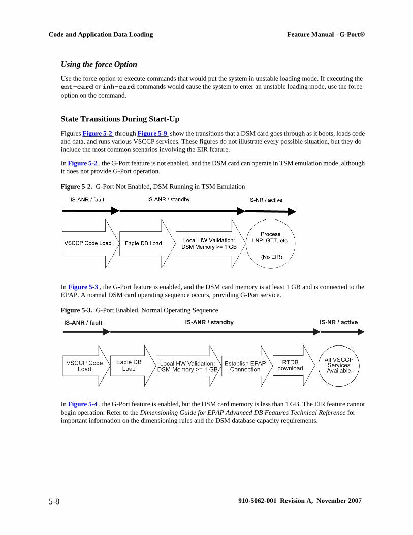
Using the force Option
Use the force option to execute commands that would put the system in unstable loading mode. If executing the ent-card or inh-card commands would cause the system to enter an unstable loading mode, use the forceoption on the command.
State Transitions During Start-Up
Figures Figure 5-2 through Figure 5-9 show the transitions that a DSM card goes through as it boots, loads codeand data, and runs various VSCCP services. These figures do not illustrate every possible situation, but they doinclude the most common scenarios involving the EIR feature.
In Figure 5-2 , the G-Port feature is not enabled, and the DSM card can operate in TSM emulation mode, althoughit does not provide G-Port operation.
Figure 5-2. G-Port Not Enabled, DSM Running in TSM Emulation
In Figure 5-3 , the G-Port feature is enabled, and the DSM card memory is at least 1 GB and is connected to theEPAP. A normal DSM card operating sequence occurs, providing G-Port service.
Figure 5-3. G-Port Enabled, Normal Operating Sequence
In Figure 5-4 , the G-Port feature is enabled, but the DSM card memory is less than 1 GB. The EIR feature cannotbegin operation. Refer to the Dimensioning Guide for EPAP Advanced DB Features Technical Reference forimportant information on the dimensioning rules and the DSM database capacity requirements.
Code and Application Data Loading Feature Manual - G-Port®
5-8 910-5062-001 Revision A, November 2007

Figure 5-4. G-Port Enabled, but DSM Memory Less Than 1 GB
In Figure 5-5 , the G-Port feature is enabled, the DSM card memory has at least 1 GB, but the DSM card is unableto connect EPAP; the G-Port cannot begin operation.
Figure 5-5. G-Port Enabled, but DSM Not Connected to EPAP
In Figure 5-6 , the G-Port feature is enabled, the DSM card has the required 1 GB memory and is connected tothe EPAP, but the DSM card is too small for the required database; the G-Port cannot begin operation. Refer tothe Dimensioning Guide for EPAP Advanced DB Features Technical Reference for important information on thedimensioning rules and the DSM database capacity requirements.
Figure 5-6. G-Port Enabled, but DSM Memory Insufficient for Database
In Figure 5-7 , the G-Port feature is enabled, the DSM card is connected to the EPAP, but the RTDB growseventually to exceed the capacity of the DSM card memory, despite its memory size of at least 1 GB (an alarm isissued when the DSM memory becomes full from the RTDB update). The G-Port cannot begin operation. Referto the Dimensioning Guide for EPAP Advanced DB Features Technical Reference for important information onthe dimensioning rules and the DSM database capacity requirements.
Feature Manual - G-Port® Code and Application Data Loading
910-5062-001 Revision A, November 2007 5-9
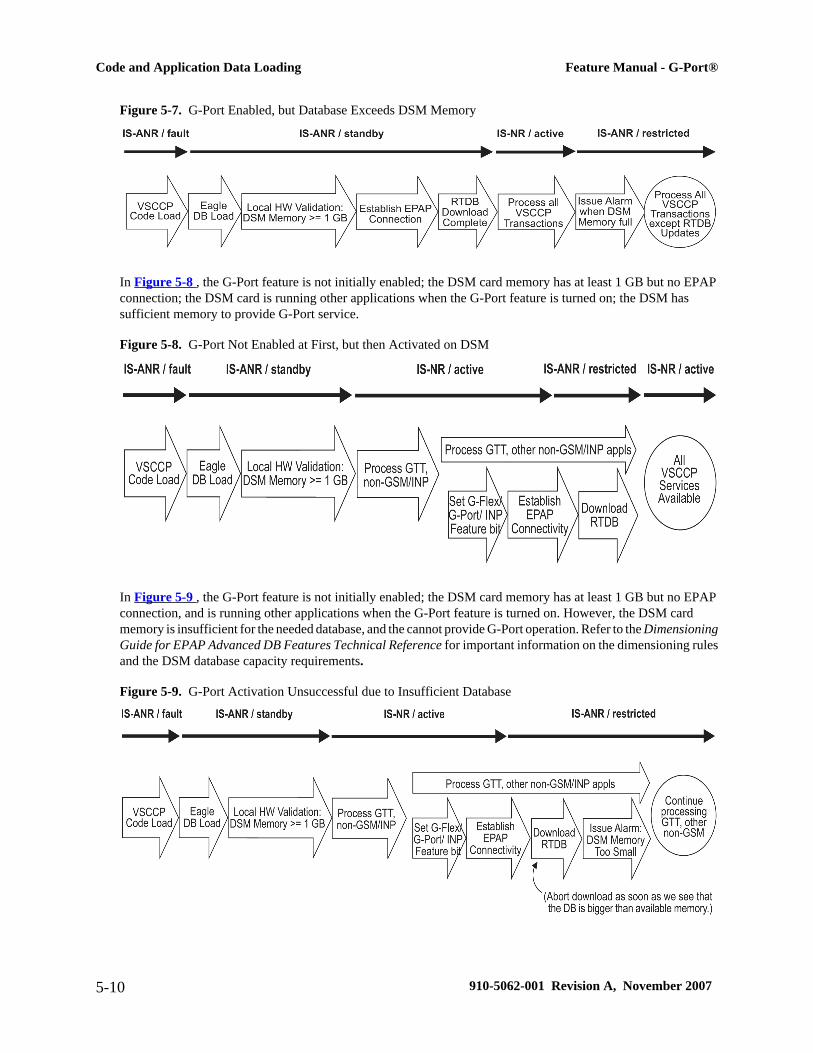
Figure 5-7. G-Port Enabled, but Database Exceeds DSM Memory
In Figure 5-8 , the G-Port feature is not initially enabled; the DSM card memory has at least 1 GB but no EPAPconnection; the DSM card is running other applications when the G-Port feature is turned on; the DSM hassufficient memory to provide G-Port service.
Figure 5-8. G-Port Not Enabled at First, but then Activated on DSM
In Figure 5-9 , the G-Port feature is not initially enabled; the DSM card memory has at least 1 GB but no EPAPconnection, and is running other applications when the G-Port feature is turned on. However, the DSM cardmemory is insufficient for the needed database, and the cannot provide G-Port operation. Refer to the DimensioningGuide for EPAP Advanced DB Features Technical Reference for important information on the dimensioning rulesand the DSM database capacity requirements.
Figure 5-9. G-Port Activation Unsuccessful due to Insufficient Database
Code and Application Data Loading Feature Manual - G-Port®
5-10 910-5062-001 Revision A, November 2007

G-Port Related AlarmsRefer to the Maintenance Manual for a complete description and the associated corrective procedure for all G-Port related UAMs.
EPAP - DSM Connection Status
The EPAP and the DSM are connected over a 100-Mbit Ethernet link and use TCP/IP. If this connection isinoperative, the DSM generates an appropriate UAM. Loss of connectivity or inability of the EPAP to communicate(for example, hardware or software failure) is detected and reported within 10 seconds.
EPAP UAMs
The maintenance blocks from the EPAP have a field used to identify error message requests. The DSM processesthe incoming maintenance blocks and generates the requested UAM. The actual EPAP UAMs are defined in theMaintenance Manual; the DSM only acts as a delivery agent.
DSM Failure
No new alarms have been created to report DSM failure. The existing card alarm UAM 013, Card is isolated fromthe system, indicates a DSM card failure. The DSM failure alarm is output to the Card Output Group.
DSM-EPAP Link
Two alarms are used to indicate the DSM-to-EPAP link status:
• 0084, IP Connection Unavailable (Major)
• 0085, IP Connection Available (Normal/Clearing)
The DSM-EPAPLink alarms are output to the Link Maintenance Output Group. See the Maintenance Manual fordetails on these UAM formats.
Example:
1 2 3 4 5 6 7 812345678901234567890123456789012345678901234567890123456789012345678901234567890 station1234 00-09-30 16:28:08 EST EAGLE 37.0.0-35.10.0** 3582.0084 ** VSCCP PORT B 1217 IP Connection Unavailable
DSM Hardware-Related Alarms
A major alarm appears when a DSM card does not have the hardware configuration required for the G-Portapplication. Loading the DSM card is automatically inhibited. Card alarms can be inhibited and uninhibited withthe inh-alm and unhb-alm commands. The DSM Hardware-Related alarms are output to the Card OutputGroup.
A major alarm is displayed when a DSM card detects that its applique memory is at least 80% full. The actualmemory usage can be displayed by entering the rept-stat-mps:loc=xxxx command.
Example:
Feature Manual - G-Port® G-Port Related Alarms
910-5062-001 Revision A, November 2007 5-11

1 2 3 4 5 6 7 812345678901234567890123456789012345678901234567890123456789012345678901234567890 station1234 99-09-30 16:28:08 EST EAGLE 37.0.0-31.7.0** 0012.0446 ** CARD 1108 VSCCP RTDB database capacity is 80% full
A critical alarm is generated when a DSM card detects that its applique memory is 95% full. Loading of theDSM card is automatically inhibited when it reaches 100% of capacity. The actual memory usage can be displayedby entering the rept-stat-mps:loc=xxxx command.
Example:
1 2 3 4 5 6 7 812345678901234567890123456789012345678901234567890123456789012345678901234567890 station1234 99-09-30 16:28:08 EST EAGLE 37.0.0-31.7.0*C 0012.0442 *C CARD 1108 VSCCP RTDB database capacity is 95% full
When the alw-card command is executed, loading of the DSM card is attempted. The following messageappears, indicating that card loading is no longer inhibited.
Example:
1 2 3 4 5 6 7 812345678901234567890123456789012345678901234567890123456789012345678901234567890 station1234 00-09-30 16:28:08 EST EAGLE 37.0.0-35.10.00012.0423 CARD 1108 VSCCP Card reload attempted
DSM Database Audit Alarm
During an audit of the DSM cards, the status of the RTDB is examined and an alarm is raised when a corrupteddatabase is found. When any RTDB database becomes corrupted, a major alarm is raised. The DSMDatabase Auditalarm is output to the Card Output Group.
Example:
1 2 3 4 5 6 7 812345678901234567890123456789012345678901234567890123456789012345678901234567890 station1234 00-09-30 16:28:08 EST EAGLE 37.0.0-35.10.0** 0012.0443 ** CARD 1108 VSCCP RTDB Database is corrupted
DSM Database Alarms
During the operation of DSM cards, the status of databases is examined and alarms can be raised.
When a DSM card's RTDB is inconsistent (that is, DSM card’s birthdate and level do not match the active EPAPRTDB birthdate and level), a minor alarm is raised. The DSMDatabase alarms are output to the Card OutputGroup.
Example:
1 2 3 4 5 6 7 812345678901234567890123456789012345678901234567890123456789012345678901234567890 station1234 00-09-30 16:28:08 EST EAGLE 37.0.0-35.10.0* 0012.0444 * CARD 1108 VSCCP RTDB Database is inconsistent
When the RTDB database download is in-process or after an update faileds, the database is in an incoherent state.A alarm is raised.
Example:
G-Port Related Alarms Feature Manual - G-Port®
5-12 910-5062-001 Revision A, November 2007

1 2 3 4 5 6 7 812345678901234567890123456789012345678901234567890123456789012345678901234567890 station1234 00-09-30 16:28:08 EST EAGLE 37.0.0-35.10.0* 0012.0448 * CARD 1108 VSCCP RTDB Database is incoherent
When an inconsistent, incoherent, or corrupted DSM RTDB has been fixed when the DSM card is in an is-nrcondition, an alarm is raised.
Example:
1 2 3 4 5 6 7 812345678901234567890123456789012345678901234567890123456789012345678901234567890 station1234 00-09-30 16:28:08 EST EAGLE 37.0.0-35.10.00012.0445 CARD 1108 VSCCP RTDB Database has been corrected
G-Port Subsystem Alarms
The same alarms that are output for an SCCP subsystem are output for the G-Port functions (including G-Porttraffic). See Table 5-1 .
Table 5-1. G-Port Subsystem Alarms
UAM # Severity Message TextOutput Group
(UI Output Direction)
0328 None SCCP is available gtt
0329 None SCCP capacity normal, card(s) abnormal gtt
0330 Major SCCPTPS Threshold exceeded gtt
0331 Critical SCCP is not available gtt
0335 None SCCP is removed gtt
0336 Major LIM(s) have been denied SCCP service gtt
0526* None Service is available sys_maint
0527* Minor Service abnormal sys_maint
0528* Critical Service is not available sys_maint
0529* Critical Service is disabled sys_maint
0530* None Service is removed sys_maint
*GPORT will display in the text of the message if the G-Port feature is enabled without the additional features of A-Portor IGM being enabled. If the A-Port and/or IGM features are enabled, the text GPORT will be replaced with the text MNP.
G-Port Related UIMsG-Port UIM formats for the EGTT feature support GTT requirements.
The EAGLE 5 ISS Maintenance Manual contains a complete description of all UIM text and formats. If the G-Port is provisioned, then the following UIMs (Table 5-2 ) are used.
Feature Manual - G-Port® G-Port Related UIMs
910-5062-001 Revision A, November 2007 5-13

Table 5-2. G-Port UIMs
UIM Text Description ActionOutput Group
(UI Output Direction)
1035 SCCP rsp did notroute - invalid GTI
The SCCP response did not route dueto an invalid GTI
Use a valid GTI in the CGPApart of the query
gtt
1036 SCCP rsp did notroute - invalid TT
The SCCP response did not route dueto an invalid TT
Provision the CGPATT in theGTT TT table
gtt
1037 SCCP rsp did notroute - bad Xlation
The SCCP response did not route dueto a bad translation
Provision the CGPAGTAaddress in the GTT database
gtt
1038 SCCP rsp did notroute - SSP not TruePC
The SCCP response did not route dueto SSP is not true point code
Use the true point code in theCGPA point code or OPC of thequery
gtt
1039 SCCP rsp did notroute - bad Selectors
The SCCP response did not route dueto invalid selectors
Provision the CGPAGTI, TT,NP, and NAI in the EGTTselector table
gtt
1169 SCCP rcvd invTCAP portion
This indicates that SCCP discarded amessage because the TCAP providedin the called party address is invalidin the EAGLE 5 ISS.
No action is necessary. application subsystem
1227 SCCP did not route -DPC not in MAP tbl
This message indicates that SCCPdid not route a message because thedestination point code was not in themated application (MAP) table. Themessage was discarded.
If the DPC indicated in themessage should not be routed to,no further action is necessary.
gtt
1230 SCCP did not route -SS not in MAP tbl
This message indicates that SCCPdid not route a message because thedestination subsystem was not in theMated Application (MAP) table. Themessage was discarded.
No action is necessary. gtt
1242 Conv to intl num - DfltCC not found
Conversion to international numberfailed because default CC was notfound
Define the default CC withchg-stpopts :defcc=xxx
application subsystem
1243 Conv to intl num - DfltNC not found
Conversion to international numberfailed because default NC was notfound
Define the default NDC withchg-stpopts :defndc=xxxxx
application subsystem
1246 Invalid length ofconditioned digits
Invalid length of condition- ed digits(length of conditioned internationalnumber is less than 5 or greater than15)
Use an international numberwith length in the acceptablerange
application subsystem
1256 MNP Circular RouteDetected
This message indicates the networkhas incorrect number portability datafor a subscriber.
Verify and update numberportability data.
application subsystem
1294 Invalid digits inMAPMSISDNparameter
No digits found in MAP MSISDN
parameter
Specify valid digits in theMSISDN
application subsystem
1295 Translation PC isEagle’s
PC translation is invalid because it isone of EAGLE 5 ISS’s PCs
Change the point code application subsystem
G-Port Related UIMs Feature Manual - G-Port®
5-14 910-5062-001 Revision A, November 2007

UIM Text Description ActionOutput Group
(UI Output Direction)
1296 Translation PC type isANSI
PC translation is invalid because it isan ANSI point code
Change the point code application subsystem
1297 Invalid length ofprefix/suffix digits
Attempted digit action of prefixingentity ID is invalid because combinedlength of entity ID and GT digits wasgreater than 21 digits
Change the attempted digitaction or decrease the length ofthe entity ID and/or GT digits
application subsystem
1374 SMS NP destinationaddress decode failed
An error was detected during decodeof SMS message destination address.
The message should be analyzedto determine the error, and theoriginating node should becontacted to send correctedmessage.
application subsystem
1375 SMS NP failed tomodify TCAPmessage
The formatted outbound digit stringlength generated by SMS NP forencoding the TCAP messageexceeded system limits.
The message and outbounddigits formatting options shouldbe analyzed to determine theerror and the originating node orthe requested outbound digitformatting option should bemodified to correct the encodingerror.
application subsystem
1376 SMS NP outbounddigits leng exceedlimit
During processing of SMS message,the formatted outbound digit stringlength exceeded limit for number ofdigits.
The message and the digit formatprovisioning should be analyzedto determine the error and theoriginating node or the requestedoutbound digit formatting optionshould be modified to correct theencoding error..
application subsystem
G-Port MeasurementsRefer to the Maintenance Manual for detailed measurement usage information.
OAM Based Measurements
G-Port measurements are available via the FTA (File Transfer Area) feature and not directly via EAGLE 5 ISSterminals. The File Transfer Area feature supports the transfer of file data between an EAGLE 5 ISS and a remotecomputer. It provides the capability to download files from the EAGLE 5 ISS via a data communications link. Thedata communications link is accessed through a dial-up modem using one of the EAGLE 5 ISS’s RS-232 I/O ports.The link is illustrated in Figure 2-21 “” on page 2-35.
See the Commands Manual for details about using FTA commands, which are:
• Activate File Transfer: act-file-trns
• Copy to or from Transfer Area: copy-fta
• Delete Entry from File Transfer Area: dlt-fta
• Display File Transfer Area: disp-fta-dir
Feature Manual - G-Port® G-Port Measurements
910-5062-001 Revision A, November 2007 5-15
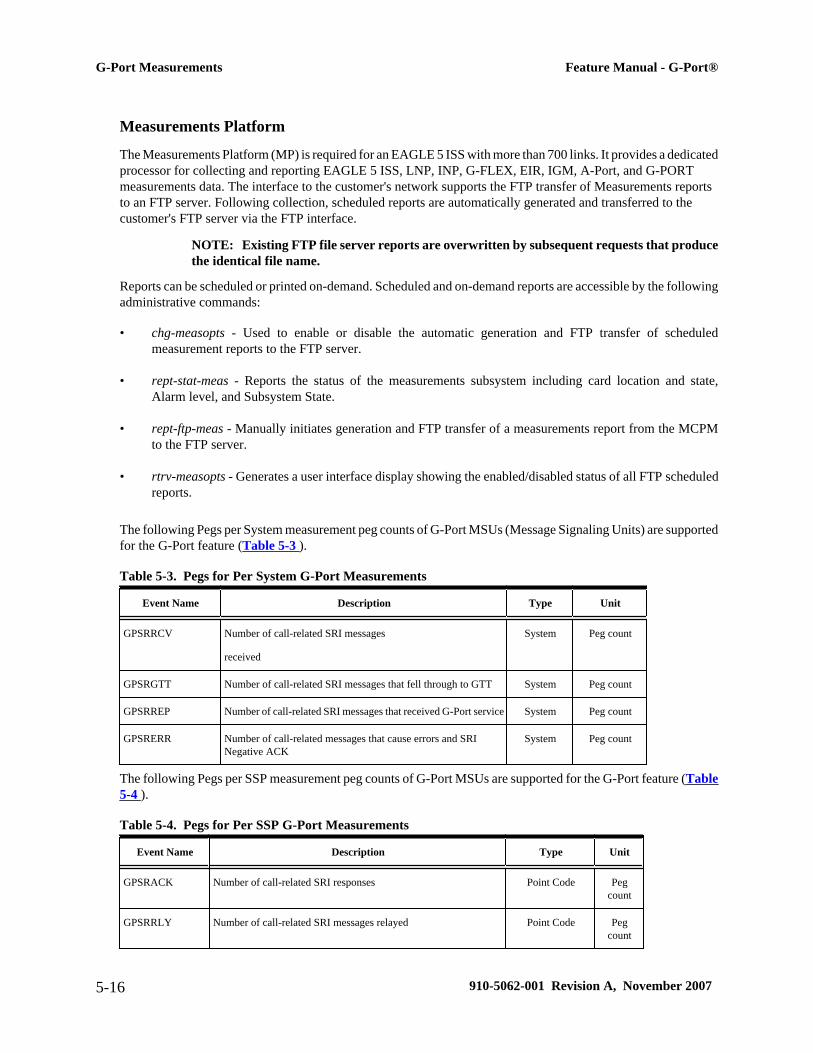
Measurements Platform
The Measurements Platform (MP) is required for an EAGLE 5 ISS with more than 700 links. It provides a dedicatedprocessor for collecting and reporting EAGLE 5 ISS, LNP, INP, G-FLEX, EIR, IGM, A-Port, and G-PORTmeasurements data. The interface to the customer's network supports the FTP transfer of Measurements reportsto an FTP server. Following collection, scheduled reports are automatically generated and transferred to thecustomer's FTP server via the FTP interface.
NOTE: Existing FTP file server reports are overwritten by subsequent requests that producethe identical file name.
Reports can be scheduled or printed on-demand. Scheduled and on-demand reports are accessible by the followingadministrative commands:
• chg-measopts - Used to enable or disable the automatic generation and FTP transfer of scheduledmeasurement reports to the FTP server.
• rept-stat-meas - Reports the status of the measurements subsystem including card location and state,Alarm level, and Subsystem State.
• rept-ftp-meas - Manually initiates generation and FTP transfer of a measurements report from the MCPMto the FTP server.
• rtrv-measopts - Generates a user interface display showing the enabled/disabled status of all FTP scheduledreports.
The following Pegs per System measurement peg counts of G-Port MSUs (Message Signaling Units) are supportedfor the G-Port feature (Table 5-3 ).
Table 5-3. Pegs for Per System G-Port Measurements
Event Name Description Type Unit
GPSRRCV Number of call-related SRI messages
received
System Peg count
GPSRGTT Number of call-related SRI messages that fell through to GTT System Peg count
GPSRREP Number of call-related SRI messages that received G-Port service System Peg count
GPSRERR Number of call-related messages that cause errors and SRINegative ACK
System Peg count
The following Pegs per SSP measurement peg counts of G-Port MSUs are supported for the G-Port feature (Table5-4 ).
Table 5-4. Pegs for Per SSP G-Port Measurements
Event Name Description Type Unit
GPSRACK Number of call-related SRI responses Point Code Pegcount
GPSRRLY Number of call-related SRI messages relayed Point Code Pegcount
G-Port Measurements Feature Manual - G-Port®
5-16 910-5062-001 Revision A, November 2007
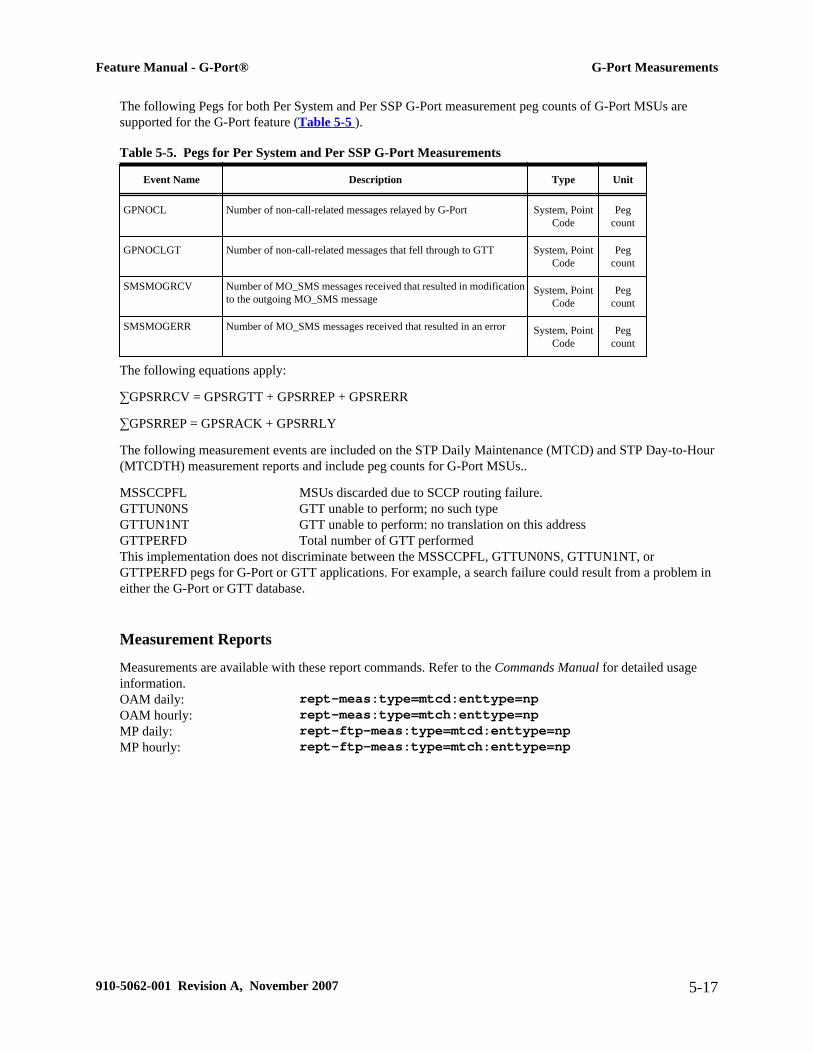
The following Pegs for both Per System and Per SSP G-Port measurement peg counts of G-Port MSUs aresupported for the G-Port feature (Table 5-5 ).
Table 5-5. Pegs for Per System and Per SSP G-Port Measurements
Event Name Description Type Unit
GPNOCL Number of non-call-related messages relayed by G-Port System, PointCode
Pegcount
GPNOCLGT Number of non-call-related messages that fell through to GTT System, PointCode
Pegcount
SMSMOGRCV Number of MO_SMS messages received that resulted in modificationto the outgoing MO_SMS message
System, PointCode
Pegcount
SMSMOGERR Number of MO_SMS messages received that resulted in an error System, PointCode
Pegcount
The following equations apply:
∑GPSRRCV = GPSRGTT + GPSRREP + GPSRERR
∑GPSRREP = GPSRACK + GPSRRLY
The following measurement events are included on the STP Daily Maintenance (MTCD) and STP Day-to-Hour(MTCDTH) measurement reports and include peg counts for G-Port MSUs..
MSSCCPFL MSUs discarded due to SCCP routing failure.GTTUN0NS GTT unable to perform; no such typeGTTUN1NT GTT unable to perform: no translation on this addressGTTPERFD Total number of GTT performedThis implementation does not discriminate between the MSSCCPFL, GTTUN0NS, GTTUN1NT, orGTTPERFD pegs for G-Port or GTT applications. For example, a search failure could result from a problem ineither the G-Port or GTT database.
Measurement Reports
Measurements are available with these report commands. Refer to the Commands Manual for detailed usageinformation.OAM daily: rept-meas:type=mtcd:enttype=npOAM hourly: rept-meas:type=mtch:enttype=npMP daily: rept-ftp-meas:type=mtcd:enttype=npMP hourly: rept-ftp-meas:type=mtch:enttype=np
Feature Manual - G-Port® G-Port Measurements
910-5062-001 Revision A, November 2007 5-17

G-Port Measurements Feature Manual - G-Port®
5-18 910-5062-001 Revision A, November 2007
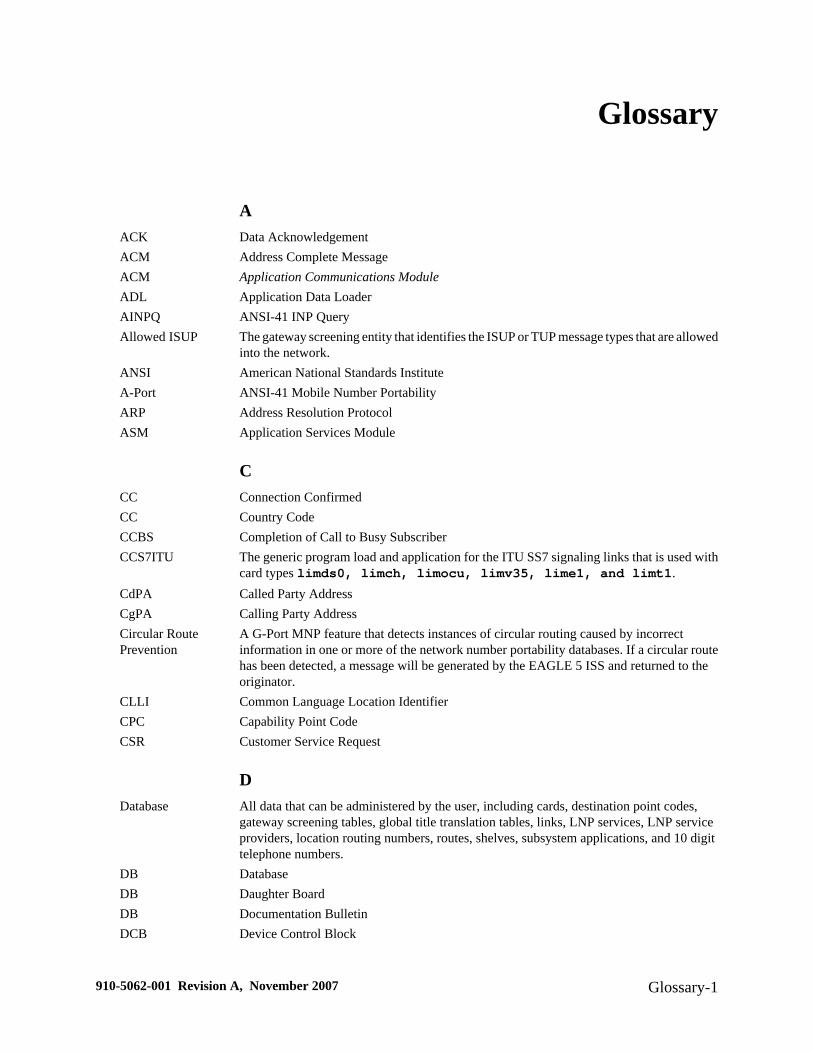
Glossary
AACK Data AcknowledgementACM Address Complete MessageACM Application Communications ModuleADL Application Data LoaderAINPQ ANSI-41 INP QueryAllowed ISUP The gateway screening entity that identifies the ISUP or TUP message types that are allowed
into the network.ANSI American National Standards InstituteA-Port ANSI-41 Mobile Number PortabilityARP Address Resolution ProtocolASM Application Services Module
CCC Connection ConfirmedCC Country CodeCCBS Completion of Call to Busy SubscriberCCS7ITU The generic program load and application for the ITU SS7 signaling links that is used with
card types limds0, limch, limocu, limv35, lime1, and limt1.CdPA Called Party AddressCgPA Calling Party AddressCircular RoutePrevention
A G-Port MNP feature that detects instances of circular routing caused by incorrectinformation in one or more of the network number portability databases. If a circular routehas been detected, a message will be generated by the EAGLE 5 ISS and returned to theoriginator.
CLLI Common Language Location IdentifierCPC Capability Point CodeCSR Customer Service Request
DDatabase All data that can be administered by the user, including cards, destination point codes,
gateway screening tables, global title translation tables, links, LNP services, LNP serviceproviders, location routing numbers, routes, shelves, subsystem applications, and 10 digittelephone numbers.
DB DatabaseDB Daughter BoardDB Documentation BulletinDCB Device Control Block
910-5062-001 Revision A, November 2007 Glossary-1

DCM Database Communication ModuleThe DCM provides IP connectivity for applications. Connection to a host is achievedthrough an ethernet LAN using the TCP/IP protocol.
DEFCC Default Country CodeDestination The node to which the signaling link traffic is routed. This destination is identified by a
point code, either a full point code or a cluster point code.DN Directory number
A DN can refer to any mobile or wireline subscriber number, and can include MSISDN,MDN, MIN, or the wireline Dialed Number.
DPC Destination Point CodeThe point code of the signaling point to which the MSU is routed. This point code can beadjacent to the EAGLE 5 ISS, but does not have to be.
DPCI Destination Point Code InternationalDSM Database Service Module.
EEA Expedited Data AcknowledgmentEGTT Enhanced Global Title TranslationEIR Equipment Identity RegisterEnhanced Global TitleTranslation
A feature that is designed for the signaling connection control part (SCCP) of the SS7protocol. The EAGLE 5 ISS uses this feature to determine to which service database to sendthe query message when a Message Signaling Unit (MSU) enters the system.
EPAP EAGLE Provisioning Application ProcessorES Encoding SchemeES Extension ShelfESD Electro-Static DischargeETSI European Technical Standards Institute
FFAK Feature Access Key.FSM Finite State MachineFTA File Transfer Area.FTP Feature Test PlanFTP File Transfer Protocol.
GGB Gigabyte — 1,073,741,824 bytesG-Flex GSM Flexible numbering
A feature that allows the operator to flexibly assign individual subscribers to HLRs androute signaling messages, based on subscriber numbering, accordingly.
GMSC Gateway MSCGPDB G-Port DatabaseGPL Generic Program LoadG-Port GSM Mobile Number Portability
Feature Manual - G-Port®
Glossary-2 910-5062-001 Revision A, November 2007

A feature that provides mobile subscribers the ability to change the GSM subscriptionnetwork within a portability cluster, while retaining their original MSISDN(s).
GPSM-II General Purpose Service ModuleGSM Global System for Mobile CommunicationsGT Global Title Routing IndicatorGTA Global Title AddressGTAI Global Title Address InformationGTI Global Title Translation IndicatorGTT Global Title Translation.GWS Gateway Screening.
HHLR Home Location RegisterHOMERN Home Network Routing Number Prefix
IIAM Initial Address MessageID IdentityID Identity, identifierIDP Initial detection pointIGM IS41 GSM MigrationIGTT Intermediate GTT
An EAGLE 5 ISS feature that routes a Global Title message based on the Global TitleTranslation.
IMSI International Mobile Station IdentifierIMT Inter-Module-Transport
The communication software that operates the inter-module-transport bus on all cardsexcept the LIMATM, DCM, DSM, and HMUX.
IN Intelligent NetworkINAP Intelligent Network Application ProtocolINE Intelligent Network EntityINE Interrogating Network EntityINP INAP-based Number PortabilityINP Intelligent Network (IN) PortabilityINP INAP-based Number PortabilityIntegrated ServicesDigital Network
The network services that provide end-to-end digital connections to which users have accessto a wide range of services through a limited set of standard user to network interfaces.
IP Intelligent PeripheralIP Internet Protocol
IP7 Tekelec's Internet Protocol to SS7 InterfaceIS-41 Interim Standard 41, same as and interchangeable with ANSI-41.IS-ANR In Service - Abnormal
Feature Manual - G-Port®
910-5062-001 Revision A, November 2007 Glossary-3

The entity is in service but only able to perform a limited subset of its normal servicefunctions.
ISDN Integrated Services Digital NetworkIS-NR In Service - NormalISDN Integrated Services Digital NetworkISS Integrated Signaling SystemISUP ISDN User PartITU International Telecommunications UnionITUDUPPC ITU National Duplicate Point Code
This feature applies only to 14-bit ITU national point codes. This feature allows an EAGLE5 ISS mated pair to route traffic for two or more countries that may have overlapping pointcode values.
KKey For the ICNP feature, a unique DS value used to access a table entry, consisting of a number
length and number type.KSR Keyboard Send/Receive Mode
LLIM Link Interface ModuleLink Signaling LinkLNP Local Number PortabilityLoad Sharing A type of routing used by global title translation to route MSUs This type of routing is used
when a second point code and subsystem is defined for the primary point code andsubsystem. Traffic is shared equally between the replicated point codes and subsystems.
MMAP Mated Application PartMAP Mobile Application PartMASP Maintenance and Administration Subsystem ProcessorMated Application The point codes and subsystem numbers of the service databases that messages are routed
to for global title translation.MCPM Measurement Collection and Polling ModuleMDAL Maintenance Disk and Alarm CardMIM Multi-Channel Interface ModuleMNP Mobile Number PortabilityMO Magneto OpticalMO Managed ObjectMO Mobile OriginatedMP Measurement PlatformMPS Multi-Purpose ServerMR Message RelayMRN Message Reference Number
Mated Relay Node
Feature Manual - G-Port®
Glossary-4 910-5062-001 Revision A, November 2007
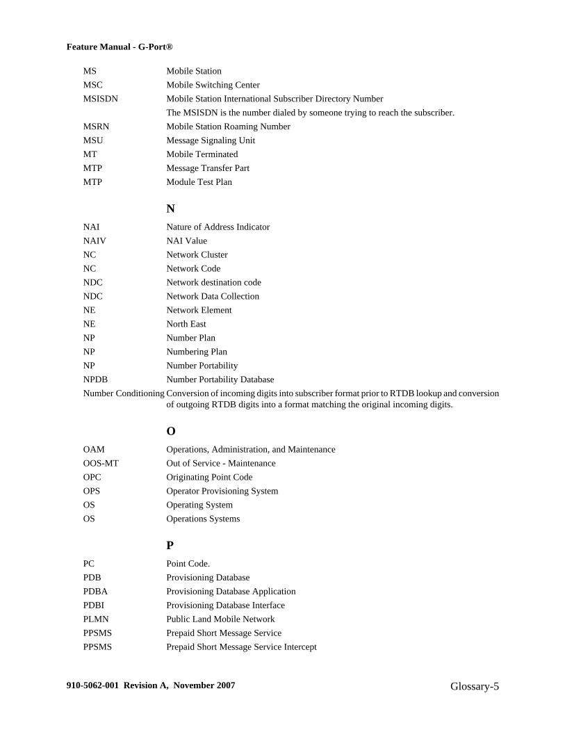
MS Mobile StationMSC Mobile Switching CenterMSISDN Mobile Station International Subscriber Directory Number
The MSISDN is the number dialed by someone trying to reach the subscriber.MSRN Mobile Station Roaming NumberMSU Message Signaling UnitMT Mobile TerminatedMTP Message Transfer PartMTP Module Test Plan
NNAI Nature of Address IndicatorNAIV NAI ValueNC Network ClusterNC Network CodeNDC Network destination codeNDC Network Data CollectionNE Network ElementNE North EastNP Number PlanNP Numbering PlanNP Number PortabilityNPDB Number Portability DatabaseNumber Conditioning Conversion of incoming digits into subscriber format prior to RTDB lookup and conversion
of outgoing RTDB digits into a format matching the original incoming digits.
OOAM Operations, Administration, and MaintenanceOOS-MT Out of Service - MaintenanceOPC Originating Point CodeOPS Operator Provisioning SystemOS Operating SystemOS Operations Systems
PPC Point Code.PDB Provisioning DatabasePDBA Provisioning Database ApplicationPDBI Provisioning Database InterfacePLMN Public Land Mobile NetworkPPSMS Prepaid Short Message ServicePPSMS Prepaid Short Message Service Intercept
Feature Manual - G-Port®
910-5062-001 Revision A, November 2007 Glossary-5

PT Portability Type
RRC Relative CostRC Restriction CriteriaRI Routing IndicatorRMTP Reliable Multicast Transport ProtocolRN Routing NumberRNIDN Routing Number - International DNRoute A path to another signaling point.RS Requirement SpecificationRTDB DSM Real-time database
SSCCP Signaling Connection Control PartSCM System Configuration Manager
System Configuration Matrix.SDS System Debug ServicesService Nature ofAddress Indicator
An internal G-Port parameter that allows a user to specify how to interpret the signalingconnection control part (SCCP) called party address (CdPA) GTA of a LOCREQ/SMSREQmessage.
SIM Subscriber Identity ModuleSIO Service Information OctetSIO Service Information Octet.SM Short MessageSMS Short Message ServiceSMSC Short Message Service CenterSMSMR Prepaid Short Message Service.SNAI Service Nature of Address IndicatorSOR Support of Optimal RoutingSOR System Out of Service RequestSP Service ProviderSP Signaling PointSpare Point Code The EAGLE ITU International/National Spare Point Code feature allows a network operator
to use the same Point Codes across two networks (either ITU-I or ITU-N). The feature alsoenables National and National Spare traffic to be routed over the same linkset. The EAGLEuses the MSU Network Indicator (NI) to differentiate the same point code of one networkfrom the other. In accordance with the SS7 standard, unique Network Indicator values aredefined for Point Code types ITU-I, ITU-N, ITU-I Spare, and ITU-N Spare.
SPC Secondary Point CodeSpare Point Code
SPC Signaling Point CodeSPC Stored Program ControlSRF Signaling Relay Function
Feature Manual - G-Port®
Glossary-6 910-5062-001 Revision A, November 2007

SRI Send Routing InformationSRI Send_Route_Information MessageSS SubsystemSS7 Signaling System #7SSN Subsystem NumberSSN SS7 Subsystem NumberSSP Subsystem Prohibited network management message.
Subsystem Prohibited SCCP (SCMG) management message. (CER)Service Switching Point (SS7 Network)
STP Signal Transfer Point.Subsystem Number The subsystem number of a given point code. The subsystem number identifies the SCP
application that should receive the message or the subsystem number of the destination pointcode to be assigned to an X.25 address or the LNP subsystem of the EAGLE 5 ISS.A value of the routing indicator portion of the global title translation data commandsindicating that no further global title translation is required for the specified entry.
TTC Table CopyTC Transaction CapabilitiesTCAP Transaction Capabilities Application PartTCP Transfer-Cluster-ProhibitedTCP Transfer Control ProtocolTCP Transmission Control ProtocolTCP/IP Transmission Control Protocol/Internet ProtocolTDM Terminal Disk Module.TLNP Triggerless LNPTPS Transactions Per SecondTSM Translation Service ModuleTSM Translation Services ModuleTT Translation Type.
UUAM Unsolicited Alarm Message.UDP User Datagram ProtocolUDT Unit Data TransferUDTS Unit Data Transfer ServiceUI User InterfaceUIM Unsolicited Information MessageUPU User Part Unavailable
VVGTT Variable Length GTT
Feature Manual - G-Port®
910-5062-001 Revision A, November 2007 Glossary-7

A feature that provides the ability to provision global title entries of varying lengths to asingle translation type or GTT set. Users are able to assign global title entries of up to 10different lengths to a single translation type or GTT set.
VSCCP VxWorks Signaling Connection Control PartThe application used by the DSM card to support the G-Flex, G-Port, INP, EIR, and LNPfeatures. If the G-Flex, G-Port, INP, or LNP feature is not turned on, and a DSM card ispresent, the VSCCP GPL processes normal GTT traffic.
Feature Manual - G-Port®
Glossary-8 910-5062-001 Revision A, November 2007

Index
-
AA-Port selector table 2-37act-file-trns 5-15act-slk 4-4, 4-16Actions Taken When Hardware Determined to be
Invalid 2-38Activate File Transfer 5-15activate signaling link 4-15, 4-16, 4-30activate signaling link, act-slk
SS7IPGW 4-15, 4-16, 4-30active 5-2active and standby EPAP servers 2-31active EPAP 2-25, 3-14, 5-2active EPAP RTDB database process 2-23active/standby EPAP servers 2-23add capability PC 4-6add mated application 4-14add route for new DPC 4-14add signaling link 4-13addresses for network 2-33ADL 5-5administer G-Port feature 3-1admonishments, documentation 1-2alarm conditions 5-2alarm totals 3-14allow DSM card 4-34allow inhibited card 4-15, 4-21, 4-29alw-card 4-4, 4-5, 4-15, 4-21, 4-29, 5-7, 5-12AMD K-6 processor 2-26AMD-K6 main board 2-38appl=vsccp 4-12, 4-18, 4-26application data loader 5-5applique board 2-26assign routes and linksets 4-6
Ccalculates checksums 2-40call-related message 2-34call-related messages 2-4call-related SRI messages 2-34capability point code 4-6, 4-7, 4-9card loading interrrupted or aborted 5-6card state 2-39caution
changing point code 4-4, 4-9init-sys command 4-4, 4-9
change GSM system options 4-6, 4-31change service providers 2-2change TCP/IP information for DSM 4-20, 4-29change true PC 4-6changing point code
caution 4-4, 4-9checksums
database corrupt alarm 2-40chg-feat
gflex=on 4-30chg-gsmopts 4-6, 4-31
Change G-Port System Options Command 3-3chg-ip-card 4-5, 4-20, 4-29chg-ip-lnk 4-5chg-sccp-serv
Change G-Flex SCCP Service Command 3-7chg-sid 4-4, 4-9chg-srvsel
Change G-Port Service Selector Command 3-5chg-stpopts 3-2, 4-6, 4-31Coherent 2-28command
chg-sid 4-4, 4-9ent-homern 4-32init-sys 4-4, 4-9
910-5062-001 Revision A, November 2007 Index-1

rtrv-homern 4-6, 4-32command examples 3-1command syntax, specifications, classes 3-1complete database reload 2-29configure EAGLE 5 SAS point code 4-4, 4-9congestion 5-2congestion indicator 5-2connectivity 2-29considerations before installing 2-36Copy to or from Transfer Area 5-15copy-fta 5-15corrupted 3-14corrupted database found 5-12CPC 4-6ctrl-feat 4-30Current 2-28customer network 2-25customer’s external provisioning system 2-25
Ddata from customer network 2-25database download 2-27database exception status 3-14database memory requirements 5-4database reload 2-29Database Service Module 2-23debug command ent-trace 2-39debugging domain name server (DNS) to IP
addressing tables 3-18dedicated network 2-31defmapvr parameter 2-44Delete Entry from File Transfer Area 5-15delete G-Flex service selector command 3-6destination point code 2-36destination point codes 4-3, 4-6dial-up modem 5-15direct routing 2-4disp-fta-dir 5-15display current IP host information 4-19, 4-28Display File Transfer Area 5-15display signaling link status, rept-stat-slk
SS7IPGW 4-16dlt-card 4-5, 4-24dlt-fta 5-15dlt-sccp-serv
Delete G-Flex SCCP Service Command 3-8DNS 3-18documentation
admonishments 1-2down 5-2download files from STP 5-15DPC 4-3, 4-6dpci, dpcn parameters 4-7DSM 2-23DSM Applique Memory Verification 2-38DSM card polls 2-25DSM Main Board Verification 2-38DSM Memory Size 5-3DSM multicast hardware 2-29DSM status 5-3DSM-based boards 5-2DSM-VxWorks-SCCP application 2-26DSM/EPAP IP link alarms 3-13dual provisioning 2-25
EE.164 MSISDN number (DN) 3-2E.164 numbers 2-36EAGLE 5 ISS mated application table 2-35EAGLE 5 SAS 1-1EAGLE Provisioning Application
Processors 2-23, 2-25ent-card 4-4, 4-5, 4-12, 4-18, 4-26, 5-8ent-dstn 4-4, 4-10ent-homern 4-32ent-ip-host 4-5, 4-19, 4-28ent-ls 4-4, 4-11ent-map 4-4, 4-14ent-rte 4-4, 4-14ent-slk 4-4, 4-13ent-srvsel 4-6, 4-33
Enter G-Port Service Selectors Command 3-5
Feature Manual - G-Port®
Index-2 910-5062-001 Revision A, November 2007

ent-trace 2-39, 3-1enter destination PC 4-10enter DPC 4-10enter G-Flex service selectors 4-6, 4-33enter linkset 4-11entering
init-sys command 4-4, 4-9entity PC 2-36entity point codes 2-35entries in the Internet Protocol host table 3-17EPAP 2-23, 2-25EPAP 'A' 5-2EPAP 'B' 5-2EPAP A 2-23, 2-33EPAP A, Link A 2-27EPAP A, Link B 2-27EPAP architecture 2-24EPAP automatically updates PDB 2-25EPAP B 2-23, 2-33EPAP B, Link A 2-27EPAP B, Link B 2-27EPAP DCBs 2-30EPAP network addresses 2-33EPAP/PDBA user interface terminal 2-33Ethernet bandwidth 2-31Ethernet links 2-26Ethernet ports 2-26ETSI GSM 03.03 standard 2-4ETSI GSM 03.66 standard 2-2ETSI standards 2-4exception status 3-14
FFile Transfer Area 5-15force option 5-8fourth octet 2-33FTA 5-15
GG-Port measurements 3-13G-Port Message Relay messages 2-36
G-Port MNP feature 1-1, 2-2G-Port system options (gsmopts) 3-3G-Port traffic alarms 5-13GDB requirements 2-37General Purpose Service Module II card 2-39Global System for Mobile communications 2-2Global Title digits (GT) 3-2global title domain 3-6global title information 2-6Global Title Translation 1-1GMSCA 2-8GPDB 2-8GPSM-II 2-39group code 4-7GSM 2-2GSM 03.66 2-36GSM 09.02 2-37GSM network operators 1-1GSM networks 1-1gsmopts commands 3-3GSMOPTS table 3-2, 3-3GTT 1-1GTT selectors 2-37
Hhardware configuration 2-38hardware configuration required 5-11hexadecimal digits 2-36high provisioning traffic situations 5-2high-traffic situations 2-26HLR translation 2-35HLRB 2-6, 2-8host=epap-a 4-20, 4-28
IIAM message 2-6, 2-7identify active EPAP 5-2identify error message requests 5-11IGM Loading Mode Support 2-39imported numbers 1-1IMSI 2-2, 2-34
Feature Manual - G-Port®
910-5062-001 Revision A, November 2007 Index-3

IMSI number 4-1IN-based MNP 2-4incoherent 3-14inconsistent 3-14incremental loading 2-28Incremental update 2-28incremental updates 2-28indirect routing 2-4INE 2-8, 2-9inh-alm 5-11inh-card 4-5, 4-23, 5-7, 5-8inhibit LIMs 5-6init-card 4-6, 4-34init-sys 4-4, 4-9init-sys command
caution 4-4, 4-9re-entering 4-4, 4-9
inoperative 5-2Integrated Signaling System 1-1intercepting MAP messages 2-4International Mobile Station Identifier 2-2international MSISDNs 2-41international number 2-5Internet Protocol host table 3-17Interrogating Network Entity 2-8, 2-9invalid hardware configuration 2-38IP host table 3-17IP link alarms 3-13IP link established 5-2IP multicasting 2-27ipaddr=192.168.122.nnn 4-20, 4-28ITU national duplicate PC 4-7ITU national point code 4-7ITUDUPPC 4-7
LLIMs 2-39LIMs denied SCCP service 5-6link alarms 3-13link congestion 5-2Link Interface Module 2-39
linksets assigned 4-6list supported pass commands 3-19LNP 1-1load balancing high-traffic situations 2-26Load Mode Status 5-3loc parameter 4-13loc=1103 4-12, 4-18, 4-26Local Memory Validation 2-38Local Number Portability 1-1local provisioning terminal 2-24logical link between MSISDN number and
IMSI 4-1loss of connectivity 2-27, 2-29
Mmain board 2-38maintenance application traffic 2-31maintenance blocks 2-30, 5-2maintenance reporting mechanism 2-33MAP messages 1-1mated application table 2-35mated pair configuration 2-25maximum number length 2-4MEA 2-39measurements 3-13memory requirements 5-4message relay 2-4message relay function 1-1Message Relay GT address 2-9, 2-10Message Relay messages 2-36Message Signaling Unit 2-39Mismatch of Equipment and Attributes 2-39MNP 2-2MNP Circular Route Prevention 2-2MNP-SRF 2-6, 2-34, 2-51MNP-SRFA 2-9, 2-10MNP-SRFB 2-8, 2-10Mobile Number Portability 1-1, 2-2Mobile Station international ISDN number 2-2mobile subscriber 2-34modem for remote access 2-24
Feature Manual - G-Port®
Index-4 910-5062-001 Revision A, November 2007
MPS 2-23MSISDN 2-2, 2-6MSISDN number 2-40, 4-1MSU trigger 3-2MSUs 2-39Multi-Purpose Server (MPS) hardware 2-23multicast updates 2-23multiple DSMs 2-28multiple trigger criteria 3-2MySQL 2-23
Nnational MSISDNs 2-41network addresses 2-33network operators 1-1non-call related messages 1-1, 2-4non-call-related message 2-34non-ported case 2-10NP database lookup 2-6npcfmti option 4-8number portability 1-1, 2-2
OOAM code 5-5OAM provisioning 2-33octets 2-33OPS 2-23Optimal Routing 2-9original number range owner network 2-6Origination point code 3-2out-of-memory condition 2-27out-of-sync 2-35out-of-sync condition 2-36overlapping database updates 2-24
Pparameter 4-9pass 4-5, 4-21, 4-30PCN
chg-sid 4-9PCN parameter
chg-sid 4-9
PDB 2-23PDBI 2-22Pegs for both Per System and Per SSP 5-17Pegs per SSP measurement peg counts 5-16ping parameter 4-21, 4-30PLMN 2-34point code 4-9portability cluster 2-34ported case 2-10ported numbers 1-1, 2-4ported subscriber 2-34porting process 2-34Prepaid Short Message Service 2-2primary DSM 2-32, 5-2private networks 2-30Provisioning Database 2-23Provisioning Database Interface 2-22provisioning DSM cards 2-25provisioning link congestion 5-2provisioning traffic situations 5-2Public Land Mobile Network 2-34
Rre-entering init-sys command 4-4, 4-9Real-Time Memory Validation 2-38Realtime Database 2-23recipient network 2-34regulatory obligations 1-1, 2-2reinitialize system 4-9Reliable Multicast Transport Protocol-II 2-27reload traffic 2-29reloading multiple DSMs 2-28remote EPAP/PDBA user interface terminal 2-33replace TSM card with DSM card 4-17, 4-25rept-stat-card 4-4, 4-5, 4-6, 4-15, 4-21, 4-23,
4-29, 4-34stat=nr 4-23
rept-stat-epap 2-39, 5-2, 5-4, 5-11rept-stat-sccp 5-2, 5-4rept-stat-slk 4-4rept-stat-sys 5-4, 5-5, 5-7
Feature Manual - G-Port®
910-5062-001 Revision A, November 2007 Index-5

RMTP channel 2-29RMTP-II 2-27RN or SP address (Entity ID) 3-2RN prefixes 2-36roaming number 2-7route table 2-36routes and linksets assigned to the DPCs 4-6Routing Number 2-6routing number prefixes 4-32routing options 2-4RS-232 I/O ports 5-15RS232 serial port 2-23RTDB 2-23RTDB database 2-23rtrv-card 4-4, 4-5, 4-12, 4-16, 4-18, 4-22, 4-24,
4-26rtrv-dstn 4-3, 4-4, 4-7, 4-8, 4-11rtrv-gsmopts
Retrieve G-Port System Options Command 3-4rtrv-homern 4-6, 4-32rtrv-ip-card 4-5, 4-20rtrv-ip-host 4-5, 4-19, 4-20, 4-28rtrv-ip-lnk 4-5rtrv-ls 4-4, 4-12rtrv-map 4-4, 4-8, 4-15rtrv-rte 4-3, 4-4, 4-7, 4-8, 4-14rtrv-sccp-serv
Retrieve G-Flex SCCP Service Command 3-8rtrv-sid 4-3, 4-4, 4-6, 4-10rtrv-slk 4-4, 4-13rtrv-srvsel 4-6, 4-33
Retrieve G-Flex Service SelectorCommand 3-6
rtrv-stpopts 3-3, 4-3, 4-7, 4-8, 4-31
SSCCP maintenance block 2-38self identification of system 4-6send status message 2-28sequential steps to activate G-Flex 4-1service provider number portability 1-1, 2-2
set trace 3-2Signaling Relay Function 1-1SIM 2-2specify ITU national PC format 4-8SRF 1-1SRF-based MNP 2-4SRI-MNP 2-36srvsel commands 3-4SS7IPGW
activate signaling link, act-slk 4-15, 4-16,4-30
display signaling link status, rept-stat-slk rept-stat-slk 4-16
SSPI/SSPN 3-2Stage 1 loading 2-28standby 5-2standby EPAP 2-25, 3-14status messages 2-27steps to activate G-Flex 4-1STP database updates sent 2-23Subscriber Identity Module 2-2subscription network 2-6subsystem numbers 2-35synchronizes the RTDBs 2-31system point code 4-7system self-identification 4-6
TTCP/IP socket 2-27TDM fixed disk 2-23TDM fixed disks 2-39TDM-resident data tables 5-5threshold monitoring 2-39trace 3-2traffic situations 2-26, 5-2transitions of DSM card 5-8trap messages 3-2trap-and-trace function 3-2trigger criteria 3-2troubleshooting network interface and routing
configuration 3-17
Feature Manual - G-Port®
Index-6 910-5062-001 Revision A, November 2007

troubleshooting private EPAP/DSM IPnetwork 3-17
true point code 4-6type=dsm 4-12, 4-18, 4-26
UUDP 2-27UIM message 2-35UIM messages 5-13unhb-alm 5-11Unstable Loading Mode 2-39User Datagram Protocol 2-27user interface 3-1user interface for maintenance and
measurements 3-10
user interface terminal 2-33
VValidation of IGM Hardware Configuration 2-38varying length numbers 2-4verify and correct IP stack ARP tables 3-18verify IS-NR card status 4-15, 4-21, 4-29VMSCA 2-7VSCCP 2-26VSCCP application 2-38VSCCP GPL 5-2VxWorks OS 2-26
Feature Manual - G-Port®
910-5062-001 Revision A, November 2007 Index-7

Feature Manual - G-Port®
Index-8 910-5062-001 Revision A, November 2007