
AMPEX Model 450B Manual - thehistoryofrecording.com Date: 1/5/2004 11:41:28 AM

DocRev 1.5, JAN2006 Copyright © DapTechnology B.V., 1998 - 2006 - All Rights Reserved

FireSpy 850/450b
PCI Form factor
FireSpy850/450b block diagram
The FireSpy850 and FireSpy450b bus analyzers complete the second generation of FireWire analyzers offered by Dap-Technology. Based on the industry leading FireSpy800, the all new and enhanced architecture of the FireSpy810, as well as the form factor advantages introduced with the FireSpy3850, make these two new PCI form factor analyzer cards the most compelling package for card-based 1394 analysis solutions found in the industry. The PCI format takes flexibility to a higher level. This solution enables users to install the FireSpy hardware in any PC that has at least one PCI slot available. This allows for installation of the FireSpy Analyzer in developers’ existing PC’s, rugged field service laptop or lunchbox computer. Both the FireSpy850 and FireSpy450b are equipped with 1 GB of on-board memory. The units offer extensive hardware filtering and trigger possibilities due to efficient programmable logic and an on-board processor. They support up to 800Mb (400Mb for the FS450b) transfer rate and are fully IEEE 1394b compliant. Three bilingual or Beta 1394 ports (depending on model) allow for convenient connection to the system under test. As an added feature the FS450b uses dip-switches to conveniently allow the changing of PHY port speed/mode settings.
The graphical user interface runs on WindowsTM
2000 or XP. It is intuitive and offers a user-friendly way of data presentation and user control. Additionally the included API even allows you to build your own control software or interface to LabView
TM. The seamless
integration of the VS (Vehicle System) protocol (SAE Mil1394) makes the FireSpy850 or the FireSpy450b an ideal tool for many Aerospace & Defense development tasks. For long distance applications DapTechnology also offers the FS450b in an impedance matching transformer configuration, i.e. the FireSpy model FS450bT.
Key Features • IEEE 1394-1995, 1394a-2000 and 1394b-2002 compliant
• Supports 100, 200, 400, and 800Mb data transfer rates (model dependent, see specification)
• PCI 2.1 compliant
• On-board 400 MHz RISC processor and programmable logic
• 1 GByte on-board memory
• Supports WindowsTM
2000 and XP
• 3 FireWire ports
• Bus Power Provider
• Powerful software provides: o Monitor o Recorder o Commander o Scriptor (programmable in C-like language) o Generator o Filter and Trigger o Support for VS (Mil1394), AV/C, SBP2, IP1394 and IIDC
• LabViewTM
interface via Scriptor or API (to be released)
LabViewTM
is a registered trademark of National Instruments Corp. Windows
TM is a registered trademark of Microsoft Corp.

Monitor
Bus Monitoring
The Monitor gives a quick indication of activities on all three buses. This powerful tool displays the number of packets transmitted on the buses and some additional events like Bus Resets. The packets are differentiated by speed and type, including all isochronous, asynchronous, PHY and acknowledge packet types. Also, the number of packets with different error types and the IEEE 1394 bus voltage are monitored and displayed. The following information for each connected network is shown by the monitor for all three analyzing nodes and are updated in real time:
• Number of packets of specific types
• Number of packets using a specific speed • Number of acknowledge packets of specific types
• Number of error packets
• Total number of packets • Number of bus resets
• Bus voltage measurement

Recorder
SBP2 Login Sequence
VS (Mil1394) sequence with Time Slot analysis and Vertical Parity Check validation
Comparable with a logic analyzer, events and packets can be stored into FireSpy’s internal memory and viewed later on the computer to which the FireSpy is connected.
The Recorder contains the following views, which can all be switched on or off individually. Time View
The Time View enables the user to view the timing of events and packets (including acknowledge packets and the packet prefix) at a resolution of 10 ns. A time cursor is used to make time measurements. Packet View
The Packet View displays all packets in a list. Each packet can be viewed in detail, by showing its packet fields, packet layout or packet errors. Packets can be displayed as any possible packet type, so the user can find out what kind of packet an erroneous packet may be. Transaction View
The Transaction View displays a list of all complete and incomplete transactions. The details of each transaction can be displayed as a packet list or as a graphical flow diagram. Topology View
The Topology View shows the bus topology at the cursor position in a graphical representation. Note that the topology may change during recording because of node connection or disconnection. Optionally, details of connected nodes may be displayed. These details include the configuration ROM content reads during recording. Protocol View
The data transactions are shown in a tree structure showing the result of the protocol analysis supported by the FireSpy. The contents of the data transactions are shown in a format corresponding to the selected protocol format. Currently the following protocols are supported:
• VS (Mil1394)
• SBP2
• AV/C • IP1394
• IIDC Support for protocols is optional and needs to be ordered separately. For further and more detailed information on all supported protocols please see the separate “FireSpy Protocol Options” datasheet.

Filter/Trigger Settings
Trigger Sequencer
Comprehensive Filter Settings
Trigger definition for predefined AV/C control command
All FireSpys have powerful hardware trigger and filter logic to control which data will be stored in memory by the Recorder, and to be able to create a reference point in the Recorded data, i.e. the trigger point.
Trigger
The Recorder can be triggered using extensive hardware trigger logic. You can select simple trigger conditions such as trigger on a particular type of error packet or trigger when a packet fits the description of a Packet Set or any Boolean combination of the four Packet Sets.
For more advanced trigger requirements a powerful Trigger Sequencer can be used. Designed to work like a flowchart this sequencer makes definition of the most complex multi-level trigger sequences a simple and straight forward task.
For optimized buffer resource management the user can manually define the maximum amount of data to be recorded after a trigger. One can choose to use a cyclic buffer for the data stored before the trigger point. The size of this cyclic buffer can be changed for efficient storage management.
Filter
With the Recorder Filter you can skip specific packets or events. Skipped packets or events are not stored in memory by the Recorder. The packets to be skipped can be selected by type, speed, error type or by using any Boolean combination of the four Packet Sets.
Packet Sets
Both Filter and Trigger logic can use any Boolean combination of four Packet Sets. These Sets consist of any combination of primary (asynchronous or stream) packets or a PHY packet, with optional value checking on packet fields. Value checking can be performed on header fields or data fields. In case of data fields, a powerful packet editor is included to be able to put conditions on data fields of a large variety of packets.

Commander
Bus Topology and ConfigROM decoder
Reads / Writes of/to predefined CSR Registers
Send / Receive to/off BusInfoBlock location
The Commander can be used to control several aspects of a connected FireSpy. Its functionality is split-up in the following four parts. Topology
The Topology is used to display the current bus topology. When a node is connected or disconnected, the topology changes are displayed immediately. Optionally, more detailed node information can be displayed, including the configuration ROM contents. One can manually generate bus resets using a push button in the toolbar. Memory Read/Write
The Memory R/W function is used to read and or write the memory of remote nodes. Read, Write and Lock operations can be performed on a selected set of predefined addresses (like the CSR registers) or on user definable addresses. Packet Send/Receive
With the Packet S/R function, one can send all kinds of packets including PHY packets, unformatted packets and erroneous packets to a selected node. Optionally one can wait for and display the response. Both the packet sent and the packet received can be displayed as layout or field list. PHY Register Read/Write
With the PHY Register R/W function, one can read and write the registers of the local PHY and read the registers of a remote PHY-interface. The register layout and a list of all register fields are shown. The registers can easily be altered by editing the register fields and issue the "Write Changes" command.
PHY Register Map

Scriptor
C-like Scripting Language in the Script Editor
Data Editor
Customizable Control Panel Display
The Scriptor can be used to define scripts and run them on a FireSpy device. The Scriptor uses a C-like language to control almost anything of the FireSpy, including sending and receiving of packets. The Scriptor is the preferred tool for the generation of individual asynchronous packets, asynchronous sequences and the simulation of entire handshake sequences between the FireSpy and the device under test. Script editor
The Script tab is used to enter a C-like script. The powerful editor includes features like:
• Automatic indent
• Syntax coloring • API function list
• Macros to automatically generate blocks of code
• Integrated Debugger • Support for floating point data structures
Data editor
The Data tab is used to define data that can be used by the script. Several data editors are available to the user:
• Hex editor • Packet Header editor
• Packet Data editor
• File input selector Control Panel
Values can be sent to a customizable Control Panel displayed on the host computer. The Control Panel displays values that it receives by using different kinds of meters (gauge, LCD, thermometer, etc).
It is possible to send control values (e.g. values of a certain data field with the packet payload section) to a history graph to display the change of values over time. Upper and lower bounds can be defined for each control and an alarm (visual and audible) is triggered when a value is out of bounds.
The Control Panel also allows users to manually define input fields. This feature provides an easy way to, for example, define payload field values for to-be-transmitted packets during Scriptor execution or, to activate any simple or complex transaction with a click on a button. Provided control functions include buttons, sliders and numeric edit boxes.
A LabViewTM
interface is provided which allows sending/receiving of all control values to/from LabView
TM in real time.

Generator
Stream Generator
VS Stream Generator
The Generator has been optimized for the generation of isochronous and asynchronous stream data packets. It offers the most comprehensible feature set for the insertion of errors, streaming of simultaneous channels and payload definitions from stored files. Stream Generator
The Stream Generator includes a powerful graphical editor to specify slots with stream sequences to be sent for up to 31 channels.
Each sequence consists of one or more stream packets with selectable data sources that can be fixed or from file. For each sequence one can select various options such as speed, packet size and header fields, including erroneous values. The overall sequence size is customizable in multiples of Cycle Periods. All Generator slots can be run in a looped-mode continuous transmission.
Both the Stream Generator and the Scriptor can run in parallel for advanced isochronous and asynchronous combination testing.
VS Stream Generator (optional)
A special version of the Generator is included in the optional VS (Mil1394) protocol package. Specific details of this protocol like the 12.5 ms time base for STOF packet generation have been implemented in this specialized version of the Generator:
• STOF packet generation including timing adjustments
• Frame Length adjustment (preset to 12.5 ms, adjustable from 10 – 20 ms with 1 µs resolution)
• Time Slot definition for asynchronous streams
generation with 1 µs resolution
• Definitions for receive and transmit offsets • Insertion of transmission errors
• Automatic Vertical Parity Check calculation option
• Automatic Heartbeat calculation option
Note that packets may also be inserted into the frame at a 1 µs resolution using the Scriptor.
Feature Summary
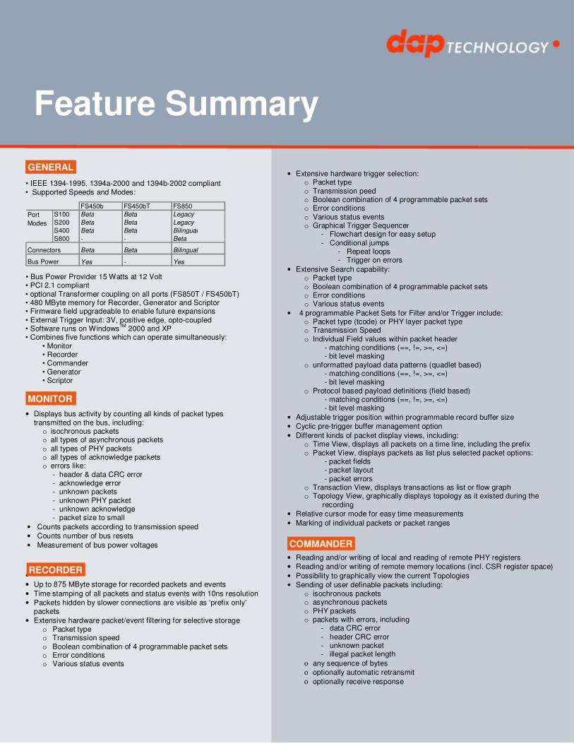
• IEEE 1394-1995, 1394a-2000 and 1394b-2002 compliant • Supported Speeds and Modes:
FS450b FS450bT FS850
S100 Beta Beta Legacy
S200 Beta Beta Legacy
S400 Beta Beta Bilingual
S800 - - Beta
Beta Beta Bilingual
Yes - Yes
Port
Modes
Connectors
Bus Power
• Bus Power Provider 15 Watts at 12 Volt • PCI 2.1 compliant • optional Transformer coupling on all ports (FS850T / FS450bT) • 480 MByte memory for Recorder, Generator and Scriptor • Firmware field upgradeable to enable future expansions • External Trigger Input: 3V, positive edge, opto-coupled • Software runs on Windows
TM 2000 and XP
• Combines five functions which can operate simultaneously: • Monitor • Recorder • Commander • Generator • Scriptor
• Displays bus activity by counting all kinds of packet types transmitted on the bus, including: o isochronous packets o all types of asynchronous packets o all types of PHY packets o all types of acknowledge packets o errors like:
- header & data CRC error - acknowledge error - unknown packets - unknown PHY packet - unknown acknowledge - packet size to small
• Counts packets according to transmission speed
• Counts number of bus resets
• Measurement of bus power voltages
•
• Up to 875 MByte storage for recorded packets and events
• Time stamping of all packets and status events with 10ns resolution
• Packets hidden by slower connections are visible as ‘prefix only’ packets
• Extensive hardware packet/event filtering for selective storage o Packet type o Transmission speed o Boolean combination of 4 programmable packet sets o Error conditions o Various status events
• Extensive hardware trigger selection:
o Packet type o Transmission peed o Boolean combination of 4 programmable packet sets o Error conditions o Various status events o Graphical Trigger Sequencer
- Flowchart design for easy setup - Conditional jumps
- Repeat loops - Trigger on errors
• Extensive Search capability: o Packet type o Boolean combination of 4 programmable packet sets o Error conditions o Various status events
• 4 programmable Packet Sets for Filter and/or Trigger include: o Packet type (tcode) or PHY layer packet type o Transmission Speed o Individual Field values within packet header
- matching conditions (==, !=, >=, <=) - bit level masking
o unformatted payload data patterns (quadlet based) - matching conditions (==, !=, >=, <=) - bit level masking
o Protocol based payload definitions (field based) - matching conditions (==, !=, >=, <=) - bit level masking
• Adjustable trigger position within programmable record buffer size
• Cyclic pre-trigger buffer management option
• Different kinds of packet display views, including: o Time View, displays all packets on a time line, including the prefix o Packet View, displays packets as list plus selected packet options:
- packet fields - packet layout - packet errors
o Transaction View, displays transactions as list or flow graph o Topology View, graphically displays topology as it existed during the
recording
• Relative cursor mode for easy time measurements
• Marking of individual packets or packet ranges
• Reading and/or writing of local and reading of remote PHY registers
• Reading and/or writing of remote memory locations (incl. CSR register space)
• Possibility to graphically view the current Topologies
• Sending of user definable packets including: o isochronous packets o asynchronous packets o PHY packets o packets with errors, including
- data CRC error - header CRC error - unknown packet - illegal packet length
ο any sequence of bytes
ο optionally automatic retransmit ο optionally receive response
MONITOR
GENERAL
COMMANDER
RECORDER

Specifications
Dimensions: Weight: Power Requirements: Regulatory compliance: Connections: Indicators: Switches: Package Content: Product warranty: Part Number: Optional Configuration: SW Add-on modules:
Half length PCI card, 15mm x 106mm x 174mm 150 g 12V, 10 Watt maximum (without providing bus power) FCC Class A 32bit/33MHz PCI connector, universal keyed (for 3.3V and 5V slots) 3 IEEE1394-connectors (bilingual) - Dip-switches for PHY port Speed/Mode Selection (FS450b and FS450bT only) FireSpy850 or FireSpy450b 1394b Cable (Beta - Beta) 1394b/1394a Cable (Bilingual – 6pin) Trigger Cable “FireWire System Architecture” Book, Mindshare 6 months limited warranty
FS85 (FireSpy810 with 6 months warranty) HSS85 (Extended Warranty for 12 months) FS85P6HSS (F850 plus VS(Mil1394) protocol software package and 18 months warranty) FS45 (FireSpy450b with 6 months warranty) HSS45 (Extended Warranty for 12 months) FS45P6HSS (FS450b plus VS(Mil1394) protocol software package and 18 months warranty) FS45T (FireSpy450bT with 6 months warranty) HSS45T (Extended Warranty for 12 months) FS45TP6HSS (FS450b plus VS(Mil1394) protocol software package and 18 months warranty)
- SBP2 protocol software package IIDC protocol software package AV/C protocol software package IP1394 protocol software package VS(Mil1394) protocol software package
• Simultaneous generation of up to 31 isochronous/asynchronous streams o Up to 872 MByte memory for Generator packets o Graphically programming of stream transmit blocks, defining:
- channel number - start and stop cycle time - send priority - speed - special header values (including forced errors) - data source, including
- fixed data (using packet editor) - data from file
• Both Generator and Scriptor can run simultaneous for stream and asynchronous packet generation
• Special VS stream generator package (optional)
•
•
• Up to to 987 MByte for Scriptor data
• Script Editor o C-like scripting language o API function list o Macros to automatically generate blocks of code o Syntax coloring o Integrated Debugger (to be released) o Floating point data values
• Data Editor o Data Input used by Scriptor
- Hex Editor - Packet Header editor - Packet Data editor - File input selector - Manual overwrite of individual payload fields
• Control Panel o Macro driven setup o diverse displays for data value presentation
- LCDs - Gauges - Alarms - History graph - Manual data input capability
• LabViewTM
Interface
• Several Sample Scripts
• Separate application for modification and extension of the following encapsulated protocol sets: o VS(Mil1394) o AV/C o SBP2
Contact Information:
DapTechnology B.V. DapUSA, Inc. Hinmanweg 11b 3640 E. Desert Willow Rd. 7575 BE Oldenzaal Phoenix, AZ 85044 the Netherlands United States of America Ph: +31 541 532941 Ph: (480) 706 7027 Fax: +31 541 530193 Fax: (480) 706 6398 [email protected] [email protected] www.daptechnology.com www.daptechnology.com
SCRITPOR
FORMAT EDITOR
GENERATOR
DHS ElMea Tools GmbHCarl Zeiss Strasse 4363322 Rödermarkph +49 6074 [email protected]
Distributed by