DOCONENT RESUME Center for Research in Vocational ...
98
.4. Ito .f., DOCONENT RESUME BD 190 883 CE 026 568 TITLE Military Curricula for Vocational S Technical. Education. Basic Electricity and Electronics Individualized Learning System. CANTRAC A-100-0010. Module Six: Parallel Circuits. Study Booklet. INSTITUTION Chief of Naval Education and Training Support, Pensacola, Fla.: Ohio State Univ., Columbus. National Center for Research in Vocational Education. !EMT NO NAVEDTIA-34258-6 PUB DATE Mar 77 NOTE 100p.: For related documents see CE 026 560-593. EDSS PRICE' MY01/PC04 Plus Postage. DESCRIPTORS Electrical Systems: *Electric Circuits: *Electricity: *Electronics: *Equipment Maintenance: Individualized Instruction: Learning Activities: Learning Modules: Postsecondary Education: Programed Instruction: *Technical Education IDENTIFIERS Military Curriculum Project ABSTRACT This individualized learning module on parallel circuits is one in a series of modlles for a course in basic electricity and electronics. The course is one of a number of military-developed curriculum packages selected for adaptation to vocational instructional and curriculum development in a civilian setting» Four lessons are included in the module: (11 Rules for Voltage'and Current, (21 Rules for Resistance and Power, (3) Variational Analysis, and (41 Troubleshooting Parallel Circuits. Bach lesson follows a typical format including-a lesson overview, a list of study resources, the lesson content, a= programmed instruction section, and a lesson summary. (progress Checks are provided for each lesson in a separate document, CE 026 562.) (LEA) i********************************************************************** * Reproductions supplied 1)* EDRS are the best that can be made * * from the original document. * *****************************p*****************************************
Transcript of DOCONENT RESUME Center for Research in Vocational ...
.4. Ito.f.,
DOCONENT RESUME
BD 190 883 CE 026 568
TITLE Military Curricula for Vocational S Technical.Education. Basic Electricity and ElectronicsIndividualized Learning System. CANTRAC A-100-0010.Module Six: Parallel Circuits. Study Booklet.
INSTITUTION Chief of Naval Education and Training Support,Pensacola, Fla.: Ohio State Univ., Columbus. NationalCenter for Research in Vocational Education.
!EMT NO NAVEDTIA-34258-6PUB DATE Mar 77NOTE 100p.: For related documents see CE 026 560-593.
EDSS PRICE' MY01/PC04 Plus Postage.DESCRIPTORS Electrical Systems: *Electric Circuits: *Electricity:
*Electronics: *Equipment Maintenance: IndividualizedInstruction: Learning Activities: Learning Modules:Postsecondary Education: Programed Instruction:*Technical Education
IDENTIFIERS Military Curriculum Project
ABSTRACTThis individualized learning module on parallel
circuits is one in a series of modlles for a course in basicelectricity and electronics. The course is one of a number ofmilitary-developed curriculum packages selected for adaptation tovocational instructional and curriculum development in a civiliansetting» Four lessons are included in the module: (11 Rules forVoltage'and Current, (21 Rules for Resistance and Power, (3)Variational Analysis, and (41 Troubleshooting Parallel Circuits. Bachlesson follows a typical format including-a lesson overview, a listof study resources, the lesson content, a= programmed instructionsection, and a lesson summary. (progress Checks are provided for eachlesson in a separate document, CE 026 562.) (LEA)
i*********************************************************************** Reproductions supplied 1)* EDRS are the best that can be made *
* from the original document. ******************************p*****************************************
1 .I: , 0,0-A- ils slo (4 -4* IF
o 111 ) tt:ot,... 0. 01 tiAoedo 0 01,41 4,,c;x4.
-3 0 040 ..a.4 ,,,e,'. - 16 1 c=. -. Iv% ctV)c)-6 0;0.:#$ -0 S1 0 Is t* t 1 c'tp 4. isi A 1 4* c cs 401
qp,....e% v".st,,,e, oso ,A,044);. ,04,9, ,1144r, 4,0 t,IN A ,Itio _,,.0
40 1 ok 7 o widr e s to re w No vslcise -; 4 , 4.. , -. -..1 ,, va,.6 0 , As 4;4.), 0 ,, e
) 0 kpo ,evoll 1, t,o.o ',%$ et4:).9;o o clA,.v co 1.4 o as 9 et *- fr414. e344.0 4Npl-,1C:1 4,1) . 117 A 0 t) 4$0 "-P70004 " %
1 0. 1 k5 et .17 tO 00 tl 1 ri tO 04 0 0 10elottflIZ° Ott% °I°C) °It 0 Cito0 0 lit 6 o To.,00 tl..1:44,0s,5101:....oc..104,0050501) 415
4.r..tPoe.'ttl 0 tP/s'eit'evcc'' cs? fAta °')0 'cAlotst..
tiOss, .. do . . . *
uti. v.0 kA 1 ollt ki: c * tt.d: k9 C it. 11 * tP 0 k.c: c"tp -0 SI
NAVEDTRA 34258-6
CHIEF OF NAVAL EDUCATION AND TRAININC
MARCH 1977
OSPARTMENT OF HEALTH.EDIKATION& WELFARENATIONAL, INSTITUTE OF
RCN/CATION
BASIC ELECTRICITY AND ELECTRONICSINDIVIDUALIZED LEARNING SYSTEM.
MODULE SIX. PARALLEL CIRCUITS.
STUDY BOOKLET.
THIS 00CLIFAE NT HAS SEEN REPRO.DICED EXACTLY AS RECEIvE0 FROMTHE PERSON OR ORGANIZATION ORIGIN.AXING IT PCHN TS OF view OR OPINIONSSTATED 00 NOT NFCESSARILY REPRESENT OFFICIAL NATIONAL otstsToTF orECHKATON POS41104 OR POLICY
1 "'' 111
'41$ .
101ILITARt CURRICULUM MATERIALS
The military-developed curriculum materials in this course
paCkage were selected by the National Center for Research inVocational Education Military Curriculum Project for dissem-.ination to the six regional Curriculum Coordination Centers andother instructional materials agencies. the purpose ofdisseminating these courses was to make curriculum materialsdeveloped by the military more accessible to vocationaleducators in the civilian setting.
The course materials were acquired, evaluated by projectstaf: and practitioners in the field, and prepared fordissemination. Materials which were specific to the nilitarywere deleted, copyrighted materials were either twitted or appro-val for their use was obtained. These course packages containcurriculum resource materials which can be adapted to supportvocational instruction and curriculum development.
3
...tel...
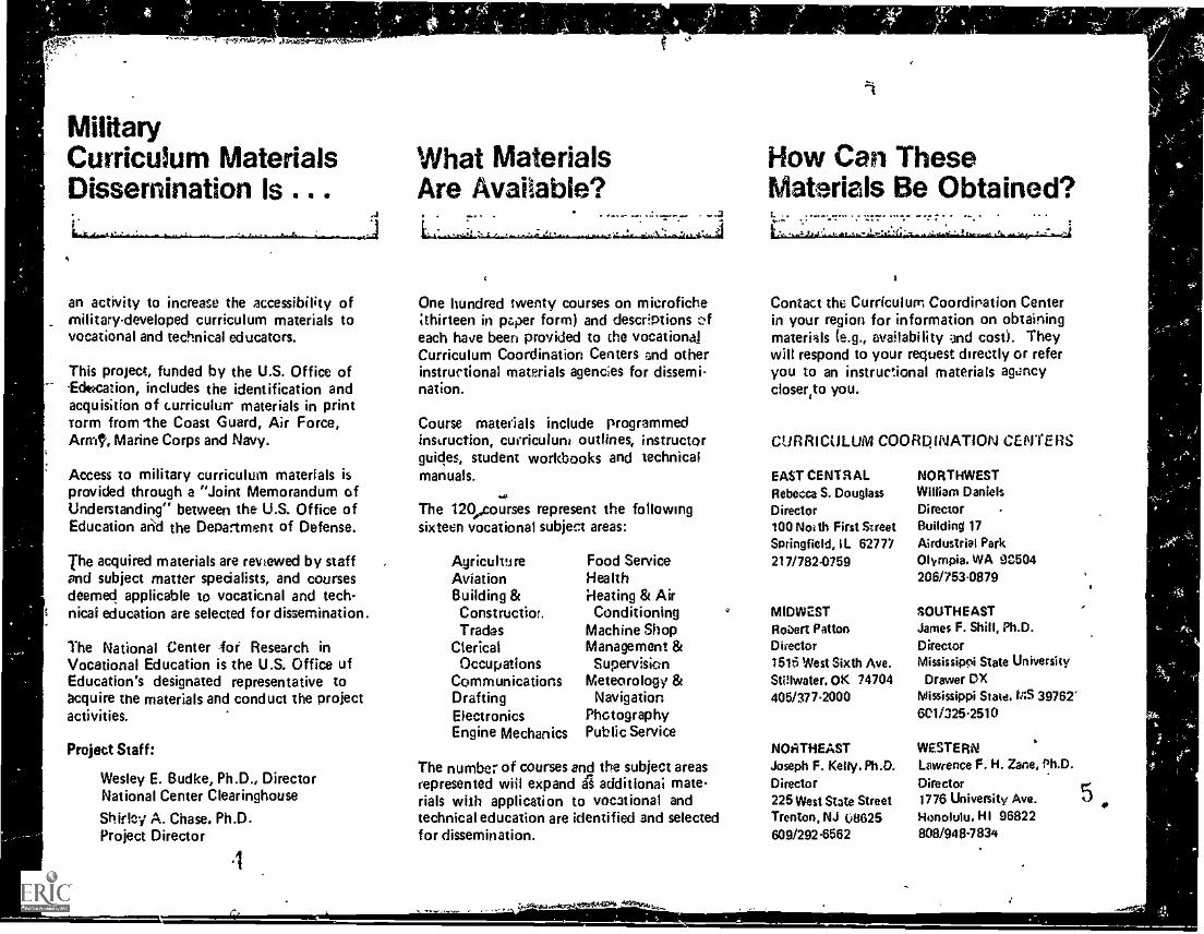
MilitaryCurriculum Materials What MaterialsDissemination is Are Available?
an activity to increase the accessibility ofmilitary-developed curriculum materials tovocational and technical educators.
This project, funded by the U.S. Office of-Education, includes the identification andacquisition of curriculun- materials in printcorm from -the Coast Guard, Air Force,Aunt, Marine Corps and Navy.
Access to military curriculum materials isprovided through a "Joint Memorandum ofUnderstanding" between the U.S. Office ofEducation and the Department of Defense.
The acquired materials are reviewed by staffand subject matter specialists, and coursesdeemed applicable to vocational and tech-nical education are selected for dissemination.
The National Center -foe Research inVocational Education is the U.S. Office ofEducation's designated representative toacquire the materials and conduct the projectactivities.
Project Staff:
Wesley E. Budke, Ph.D., DirectorNational Center Clearinghouse
Shirley A. Chase. Ph.D.Project Director
4
One hundred twenty courses on microfichethirteen in paper form) and descriptions
each have been provided to the vocationalCurriculum Coordination Centers and otherinstructional materials agencies for dissemi-nation.
Course materials include programmedinstruction, curriculum outlines, instructorguides, student workbooks and technic&manuals.
4.6
The 120ecourses represent the followingsixteen vocational subject areas:
AgricultureAviationBuilding &Construction.Trades
ClericalOccupations
CommunicationsDraftingElectronicsEngine Mechanics
Food ServiceHealthHeating & Air
ConditioningMachine ShopManagement &
SupervisionMeteorology &
NavigationPhotographyPublic Service
The number of courses end the subject areasrepresented will expand it additional materials with application to vocational andtechnical education are identified and selectedfor dissemination.
...j024.
How Can TheseMaterials Be Obtained?
Contact the Curriculum Coordination Centerin your region for information on obtainingmaterials (e.g., mailability and cost). Theywill respond to your request directly or referyou to an instructional materials agencycloser,to you.
CURRICULUM COOROINATION COVERS
EAST CENTRALRebecca S. Douglass
Director100 Noe th First StreetSpringfield, IL 62777217/782 .0759
MIDWESTRobert PattonD irector
1516 West Sixth Ave.Stillwater, OK 74704405/377.2000
NORTHEASTJoseph F. Kelly. Ph.D.Director225 West State StreetTrenton, NJ 08625609/2924562
NORTHWESTWilliam DanielsDirectorBuilding 17Airdustrial ParkOlympia. WA 92504206/753.0879
SOUTHEASTJames F. Shill, Ph.D.DirectorMississippi State University
Drawer DXMississippi State. MS 397676C1/325.2510
WESTERNLawrence F. H. Zane, Ph.D.
Director1776 University Ave. 5Honolulu, HI 968228081948-7834
t.
The National CenterMission Statement
4- .4A. . . .........4====3'717":"77..17"--"er
-
Ihe National Center for Research inVocational Education's rkion is to increasethe ability of diverse agencies, institutiors,and organizations to' solve educational prob-lems relating to individual career planning,preparation, and progression. The NationalCenter fulfills its mission by:
O
Military CurriculumMaterials for
Vocational andTechnical Education
lilfornrtien ni)d Fieldvices Civi pion
The Nr.`ici,°,1 emler lot firs^arcliin k've..tinni Erb:cntion
Generating knowledge through research
Developing educational programs andproducts
Evaluating individual program needsand outcomes
installing educational programs andprolucis
Operating information systems andservices
Conducting leadership development andtraining programs
FOR FURTHER INFORMATION ABOUTMilitary Curriculum Materials
WRITE OR CALL,Program Information OfficeThe National Center for Research in Vocational
Education6 The Ohio State University
1960 Kenny Road, Columbus, Ohio 43210Telephone: 614/4863666 or Toll Free 800/
848480 within the continental U.S.(except Ohio)
14
44, v.44
14
OVERV,I EWMODULE VI
PARALLEL CIRCUITS
In this module you will learn the rules that govern the characteristics
of parallel circuits; the relationshipi between voltage, current, resist-.
ance, and power; and the results of common troubles in parallel circuits.
For you to more easily learn the above, this module has beeq cpvided
1Into the following four lessons:
Lesson I. Rules for Voltage and Current
Lesson II. Rules for Resistance and Power.
Lessori 111. Variational Analysis
Lesson IV. Troubleshooting Parallel Circuits
TURN TO THE FOLLOWING PAGE AND BEGIN LESSON 1.
18
St.
V.
A
.4
N..
I-
/
t
BASIC ELECTRICITY AND ELECTRONICS
INDIVIDUALIZED LEARNING 'SYSTEM
ks
MODULE VILESSON I
ft
k l
Rules for Voltage and Current
I
Study Booklet
,
( 103
4
t
e
IP.
I, 1
/
-.111, v
r
0
Overview Six-I
OVERVIEW
LESSON 61..,
Rules for Voltage and Current
In this lesson you will study and learn 4bout the following:
-how Ohm's Law is applied to
parallel circuits
-voltage
-current
-practical solutions
Each of the above topics will be discussed in the order listed. As
proceed through this lesson, observe and follow directions carefully.
%D.
BEFORE YOU START THIS LESSON, PREVIEW THE LIST OF STUDY RESOURCES
ON THE NEXT PAGE.
ND
0
4DIV
Study Resources Six-I
LIST OF STUDY RESOURCES
LESSON I
Rules for Voltage and Current
To learn the material in this lesson, you have the option of choosing,
accord' - to your experience and preh.rences, any or all of the following':
STUDY SOL jr:
Lesson Narrative
Programmed Instruction
Lesson Summary 411
ENRICHMENT' ATERIAL:
NAVPERS 99400A-la "Basic Electricity, Direct Current.
Fundamentals of Electronics.. Bureau of Naval Personnel.
Washington, D.C.: U.S. Government Printing Office, 1965.
AUDIO/VISUAL:
Sound/Slide Presentation "Measurement of I g E in a Parallel Circuit"
YOU MAY, OW STUDY ANY Oft ALL OF THE RESOURCES LISTED ABOVE. YOU MAY
TAKE THE PROGRESS CHECK AT ANY TIME.
0 .5.12
a
Narrative Six-I
c'74
NARRATIVELESSON I
Rules for Voltage and Current
A Look At Parallel Circuits
In the previous module you learned about Ohm's Law relationshipsand how they apply to series Circuits. You learned certain rulesabout voltage, current, resistance, and power that are true for ser-ies circuits. It Is now time to see how Ohm's Law is applied toparallel circuits.
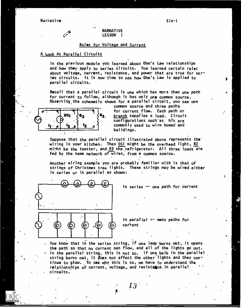
Recall that a parallel circuit Is one which has more than one pathfor current to follow, although it has only one common source.Observing the schematic shown for a parallel circuit, you see one
common source and three pathsfor current flow. Each path orbranch supplies a load. Circuitconfigurations such'as hts arecommonly used to wire homes-andbuildings.
Suppose that the parallel circuit illustrated above represents thewiring in your kitchen. Thep OS1 might be the overhead light, R2mi "ht be the toaster, and. R3 theyaefrigerator. All three loads arefed by the same network of wires, from a common source.
Another wiring example you are probably familiar with Is that ofstrings of Christmas tree lights. These strings may be wired eitherin series or in parallel as shown:
In series -- one path for current
In parallel w- many paths for
cuel-ent
You know that in the series string, if one lamp burns out, It opensthe path so that no current can flow, and all of the lights go out.
-4 in the parallel string, this is not so. If one bulb in the parallelstring burns out, it foes not affect the other lights and they con-tinue to glow. To see why this is so, we have to understand therelationships of current, voltage,, and resistalkce,in parallel
. .
circuits.
13-6
4
Narrative Six-i
Voltage
You recall that in series circuits the same current flows throughevery component. This is not true of parallel circuits. In a
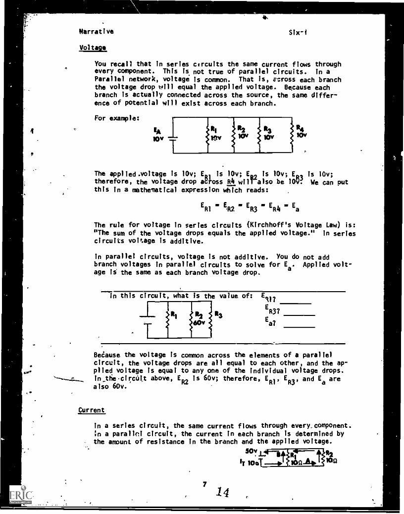
Parallel network, voltage is common. That is, v=ross each branchthe voltage drop will equal the applied voltage. Because eachbranch is actually connected across the source, the same differ-ence of potential will exist across each branch.
For example:
14 .
RI 12 R3 1 24Er, WY+ lov
The applied.voltage is 10v; E is 10v; E., is 10v; ED, is 10v;therefore, the voltage drop aefoss R4 wilralso be 109f We can putthis in a mathematical expression which reads:
ERI
= ER2 = ER3 = ER4
a. Ea
The rule for voltage in series circuits (Kirchhoff's Voltage Law) is:"The sum of the voltage drops equals the applied voltage." In seriescircuits voltage is additive.
In parallel circuits, voltage is not additive. You do not addbranch voltages in parallel circuits to solve for Ea. Applied volt-age is the same as each branch voltage drop.
In this circuit, what Is the value of: E117
ER3?
23Ea?
Beiause the voltage is common across the elements of a parallelcircuit, the voltage drops are all equal to each other, and the ap-
.
plied voltage is equal to any one of the individual voltage drops.In_tfie cii:cutt above, ER2 is 60v; therefore, ER1, ER3, and E
aare
also 60v.
Current
In a series circuit, the same current flows through every component.in a parallel circuit, the current in each branch is determined bythe amount of resistance In the branch and the applied voltage.
SCf1-1114141igli2wei bor:A 1 )114
' 14
S'
Narrative Six-1
In the circuit illustrated at the bottom of the previous page,with voltage 50v, total current is 10 amps as it leaves the sourceand arrives at junction A. Because each of the two branches has thesame resistance, the 10 amps divides and 5 amps flows through the RIbranch, and 5 amps flows through the R2 branch. At junction B, the5 amps from branch 2 joins the 5 ampsTrom branch 1 to add up to atotal current of 10 amps returning to the source.
The following two rules apply to current in parallel circuits:
1. Each branch current is determined by the resistance of the branch.2. Total current is equal to the sum of the branch currents.
Since electrons are neither c,mated nor destroyed as the currentdivides, the sum of the currents flowing in the branches must beexactly equal to the total current flowing to and from the source.
Solving for Branch Current
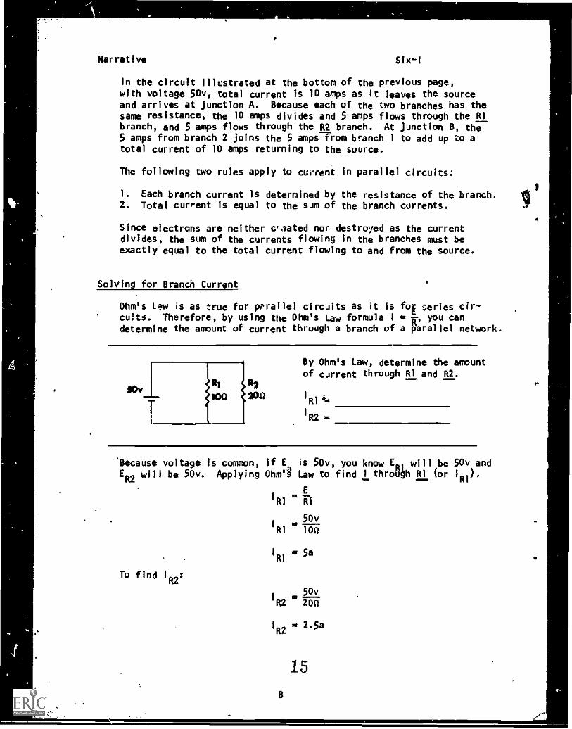
Ohm's Lew is as true for parallel circuits as it is foE series cir-cuts. Therefore, by using the Ohm's Law formula I e R, you candetermine the amount of current through a branch of a parallel network.
R2
210/111
By Ohm's Law, determine the amountof current through RI and R2.
R2 0
'Because voltage is common, if E is 50v, you know E01 will be 50v andER2
will be 50v. Applying Ohm Law to find 1 throP411 RI (or 10,
E'RI WI
50vRi 100
To find I :
R2
I
RI5a
50vR2 NU
I
R22.5a
8
15
4
-r
Narrative Slx -I
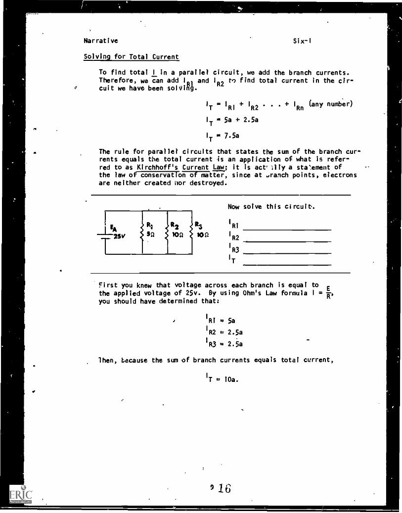
Solving for Total Current
To find total I in a parallel circuit, we add the branch currents.Therefore, we can add IR, and IR2 V) find total current in the cir-
e cult we have been solVin4.
IT
= IRI
+ IR2
. I
Rn(any number)
I
T= 5a + 2.5a
I
T= 7.5a
The rule for parallel circuits that states the sum of the branch cur-rents equals the total current is an application of what is refer-red to as Kirchhoff's Current Law; it is act'llly a steement ofthe law of co-vat or:f)liatter, since at .ranch points, electronsare neither created nor destroyed.
I
251/
12 R3
100 10 tt
Now solve this circuit.
I
R1
I
R2
1
R3
I
T
First you knew that voltage across each branch is equal tothe applied voltage of 25v. By using Ohm's Law formula I =
you should have determined that:
I
RI = 5aI
R2 = 2.5a
I
R3 = 2.5a
'then, because the sum of branch currents equals total current,
I
T = 10a.
9 16'
Narrative Six-1
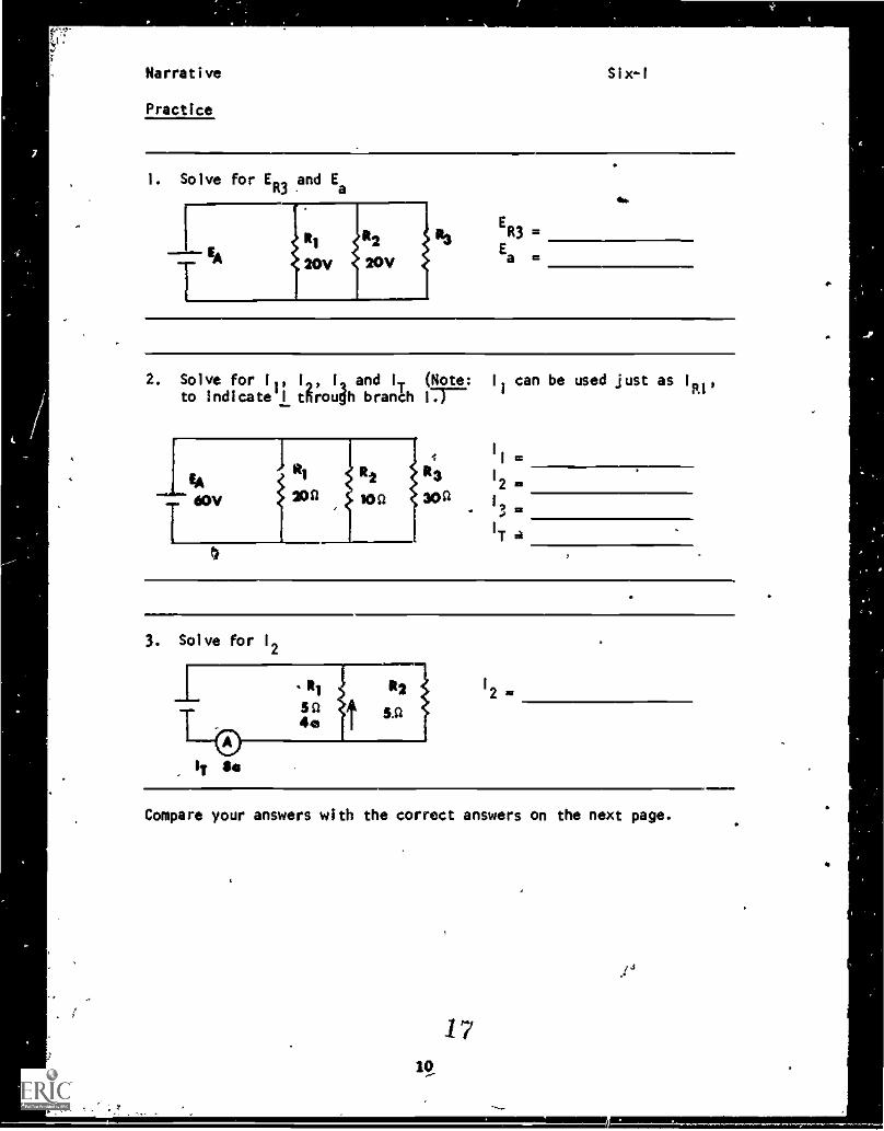
Practice
1. Solve forER3 a
nd Ea
ER3=
Ea=
4.
2. Solve for II, 1, I and IT (Note: II can be used just as 1
R1'to indicate!! tRroudh branal 17r-
LAi R
60V awl ion
T4
30th 13
IT a
3. Solve for 1
2
IIT Se
1
2
Compare your answers with the correct answers on the next page.
1710,
.i4
I
4
Narrative Six-I
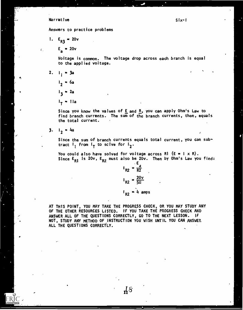
Answers to practice problems
1. ER3
20v
Ea= 20v
Voltage is common. The voltage drop across each branch is equalto the applied voltage.
2. 1
1
= 3a
1
2n 6a
13 . 2a
IT = Ila
Since you know the values of E and R, you can apply Ohm's Law tofind branch currents. The sum of the branch currents, then, equalsthe total current.
3 1
2=
Since the sum of branch currents equals total current, you can sub-tract 1, from IT to sclve for t2.
You could also have solved for voltage across RI (E = 1 x R).
Since ERI
is 20v, ER2
must also be 20v. Then by Ohm's Law you find:.E
R2 R2
20v1 WR2 5n
1
R2- 4 amps
AT THIS POINT, YOU MAY TAKE THE PROGRESS CHECK, OR YOU MAY STUDY ANYOF THE OTHER RESOURCES LISTED. IF YOU TAKE THE PROGRESS CHECK ANDANSWER ALL OF THE QUESTIONS CORRECTLY, GO TO THE NEXT LESSON. IF
NOT, STUDY ANY METHOD OF INSTRUCTION YOU WISH UNTIL YOU CAN ANSWERALL THE QUESTIDNS CORRECTLY.
P.1. Six-1
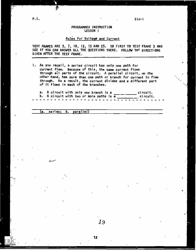
PROGRAMMEt) INSTRUCTIONLESSON I
Rules for Voltage and Current
TEST FRAMES ARE 3, 7, 10, 13, 15 AND 25. GO FIRST TO TEST FRAME 3 ANDSEE IF YOU CAN ANSWER ALL THE QUESTIONS THERE. FOLLOW THr DIRECTIONSGIVEN AFTER THE TEST FRAME.
1. As you recall, a series"circuit has only one path forcurrent flow. Because of this, the same current flowsthrough all parts of the circuit. A parallel circuit, on theother hand, has more than one path or branch for current to flowthrough. As a result, the current divides and a different partof it flows in each of the branches.
a. A circuit with only one,branch is ab. A circuit with two or more paths is a
circuit.circuit.
(a. series; b. parallel)
C
X2
_19
A
P.I. Six -f
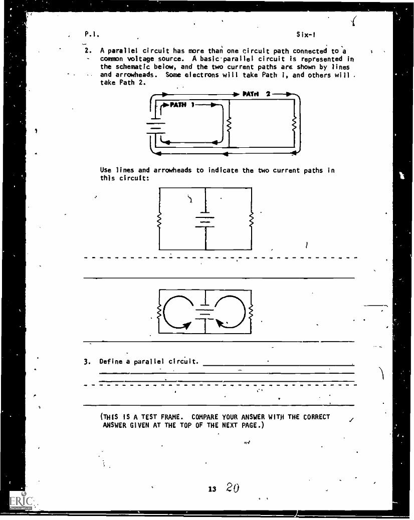
2. A parallel circuit has more than one circuit path connected to a- common voltage source. A basic-parallel circuit is represented in
the schematic below, and the two current paths are shown by linesand arrowheads. Some electrons will take Path 1, and others will .
take Path 2.
ilfiPATII 1
PATtI 2 IPM
Use lines and arrowheads to indicate the two current paths inthis circuit:
3. Define a parallel circuit.
=1111=1
(THIS IS A TEST FRAME. COMPARE YOUR ANSWER WITH THE CORRECTANSWER GIVEN AT THE TOP OF THE NEXT PAGE.)
13 20
4.4
..,
P.!. Six-I
ANSWER - TEST FRAME 3
A parallel circuit is one which has more than onepath for current flow connected to a common source.
IF YOUR ANSWER MATCHES THE CORRECT ANSWER, YOU MAY GO ON TO TESTFRAME 7. OTHERWISE, GO BACK TO FRAME 1 AND TAKE THE PROGRAMMEDSEQUENCE BEFORE TAKING TEST FRAME 3 AGAIN.
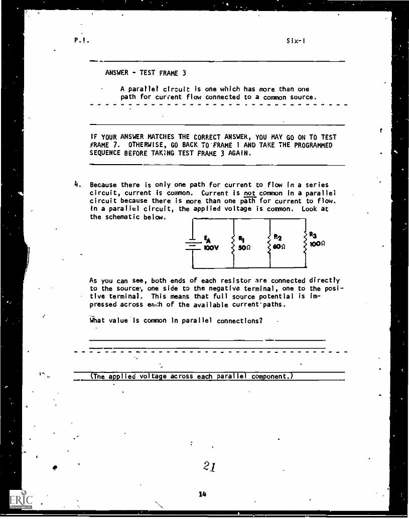
4. Because there is only one path for current to flow in a seriescircuit, current is common. Current is not common in a parallelcircuit because there is more than one pia' for current to flow.In a parallel circuit, the applied voltage is common. Look atthe schematic below.
R3
1000
As you can see, both ends of each resistor are connected directlyto the source., one side to the negative terminal, one to the posi-tive terminal. This means that full source potential is im-pressed across of the available currentpaths.
14hat valueis common In parallel connections? -
..11MmIlld....(The a. lied volta e across each parallel corn orient.)
2/
14
t
e
P.I.
a
Six-I
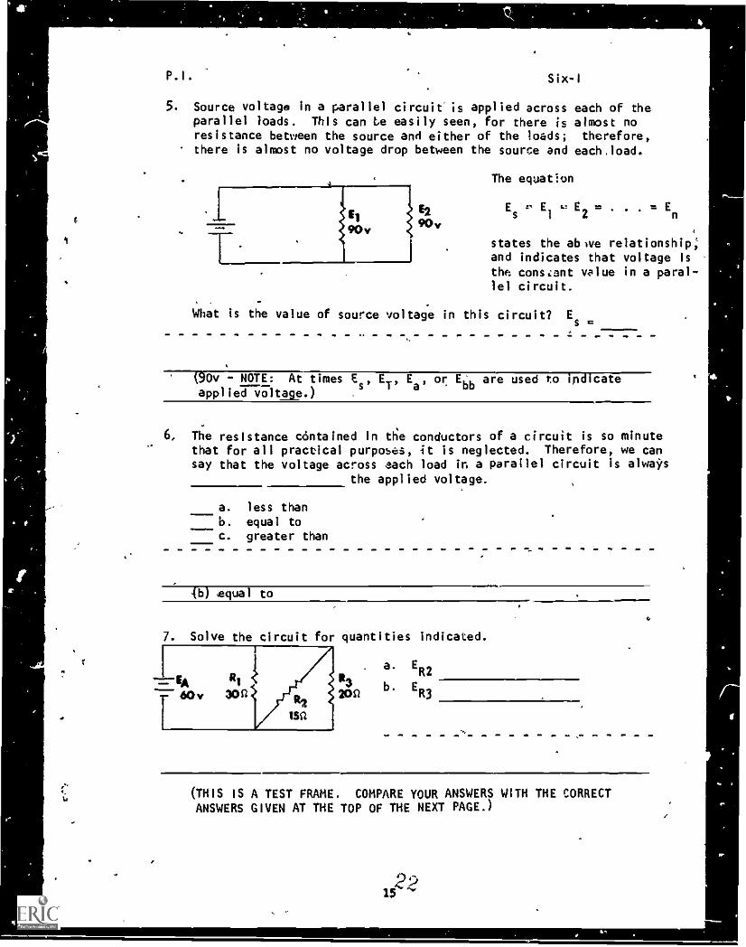
5. Source voltage In a parallel circuit'is applied across each of theparallel loads. This can Le easily seen, for there is almost noresistance between the source and either of the loads; therefore,there is almost no voltage drop between the source and each,load.
I
El
90v
The equat!on
Es
E1
= E2
states the abwe relationship;and indicates that voltage istho cons=ent value in a paral-lel circuit.
What Is the value of source voltage in this circuit? Es 11.
(90v - NOTE: At times Es
, ET'
Ea, or Ebb are used to indicate
applied v3Itage.)
6, The resistance contained in the conductors of a circuit is so minutethat for all practical purposes, it is neglected. Therefore, we cansay that the voltage across each load in a parallel circuit is always
the applied voltage.
a. less thanb. equal toc. greater than
(b) Sequa l to
. Solve the circuit for quantities indicated.
. a. ER2
3 b E243S1 R3
(THIS IS A TEST FRAME. COMPARE YOUR ANSWERS WITH THE CORRECTANSWERS GIVEN AT THE TOP OF THE NEXT PAGE.)
1522
41.
! 4
i 4o
P.I. Six-1 -
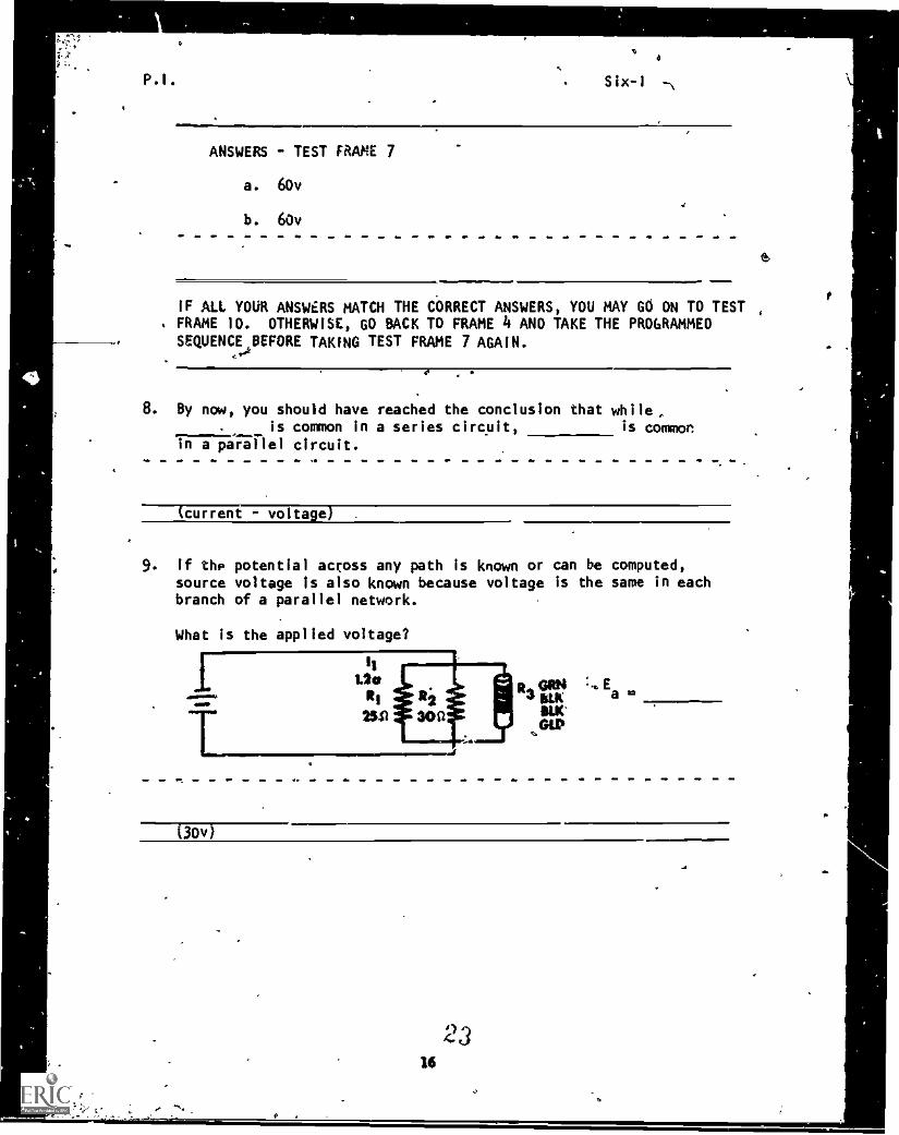
ANSWERS - TEST FRAME 7
a. 60v
b. 60v
6
IF ALL YOUR ANSWERS MATCH THE CORRECT ANSWERS, YOU MAY GO ON TO TEST ,
. FRAME 10. OTHERWISE, GO BACK TO FRAME 4 AND TAKE THE PROGRAMMEDSEQUENCE BEFORE TAKING TEST FRAME 7 AGAIN.
4,
8. By now, you should have reached the conclusion that whileis common in a series circuit, is common
in a parallel circuit.
(current - voltage)
9. If the potential across any path is known or can be computed,source voltage is also known because voltage is the same in eachbranch of a parallel network.
What is the applied voltage?
(30v)
0
16
I)4
or,
P.I. Six-I
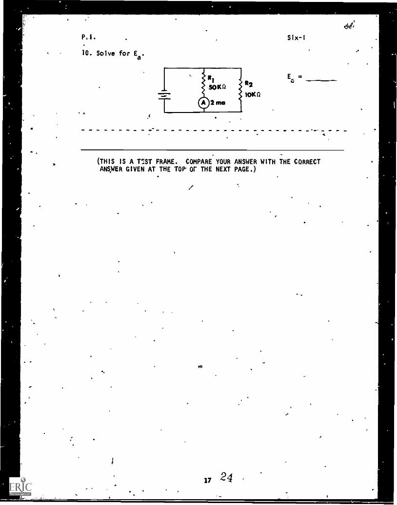
10. Solve for Ea
.
R2
10Kil
(THIS IS A ISST FRAME. COMPARE YOUR ANSWER WITH THE CORRECTANSWER GIVEN AT THE TOP or THE NEXT PAGE.)
17 24 '
ti
0
PI Six-I
ANSWER - TEST FRAME 10
100v
IF YOUR ANSWER MATCHES THE CORRECT ANSWER, YOU MAY GO ON TO TESTFRAME'13. OTHERWISE, GO BACK TO FRAME 8 AND TAKE THE PROGRAMMED
SEQUENCE BEFORE TAKING TEST ?RAM,. 10 AGAIN.
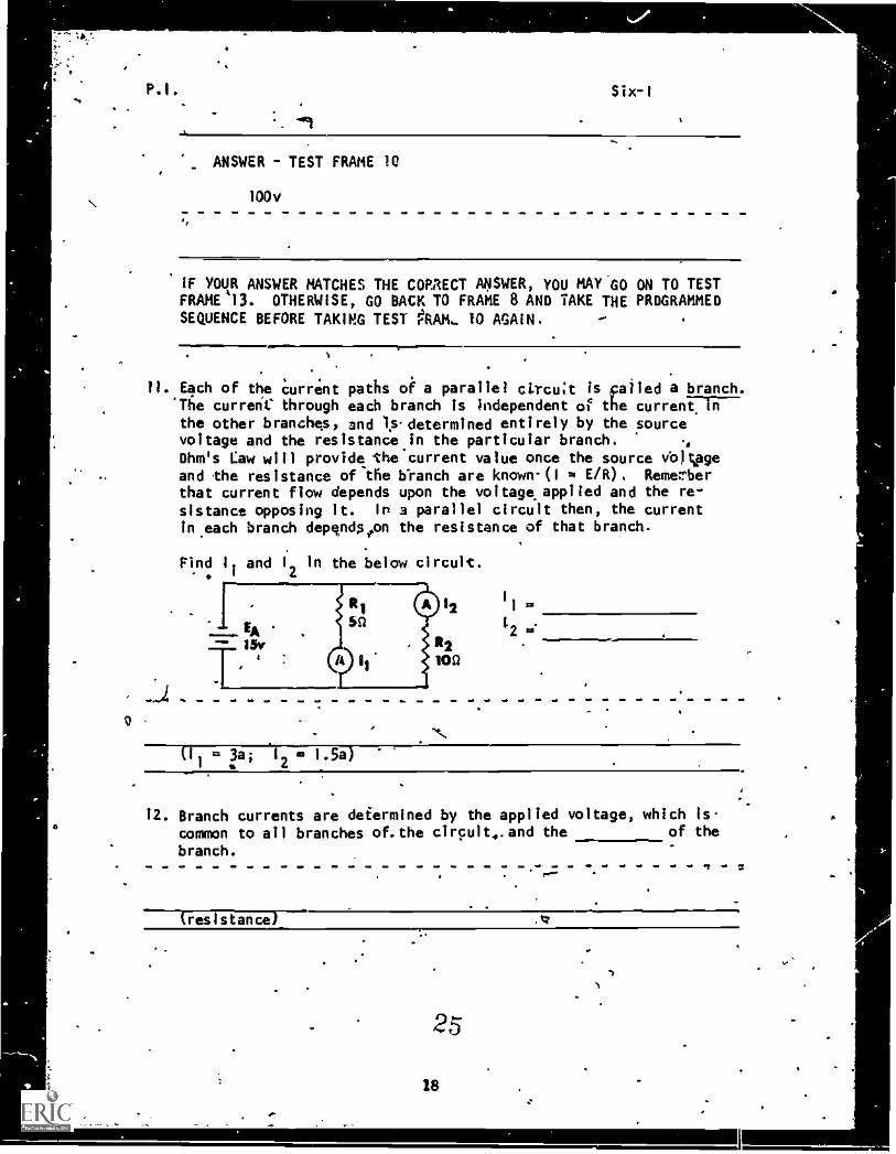
11. Each of the current paths of a parallel circuit is Failed a branch.currerie through each branch is independent of the currenTIV
the other branches, and I.s determined entirely by the sourcevoltage and the resistance in the particular branch.Ohm's Law will provide the current value once the source vbj;pgeand the resistance of the branch are known-(1 E/R). Remerberthat current flow depends upon the voltage applied and the re-sistance opposing it. In a parallel circuit then, the currentin.each branch dependston the resistance of that branch.
Find 1. and I
2in the below circuit.
I
,
EA15r
-
:
R1
5n
A 11
O 12
112
100
11
1,2is'
(I1
3a; IF= 1.5a)2
12. Branch currents are determined by the applied voltage, which iscommon to all branches of. the circuit,. and the of the
branch.
(resistance) .44
25
18
.
P.I. Six -1
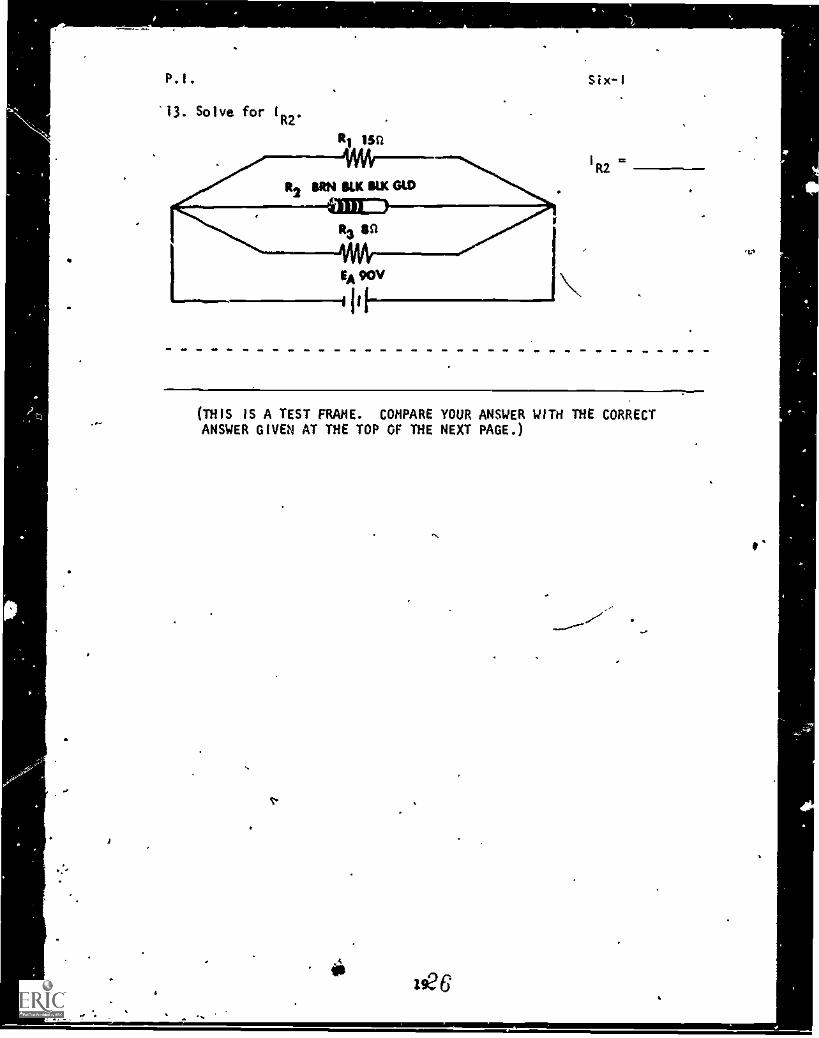
13. Solve for I
R2'
RI isn
WsR2 BM KR IM=MM.
R3 $0
.. VAIVEA 90V
1
(IF
1R212
(THIS IS A TEST FRAME. COMPARE YOUR ANSWER WITH THE CORRECTANSWER GIVEN AT THE TOP OF THE NEXT PAGE.)
v. .
is
./'
P.I. Six-1
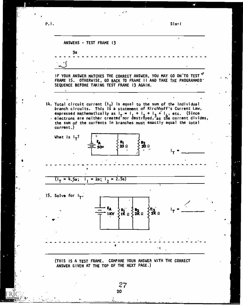
ANSWERS - TEST FRAME 13
9a
IF YOUR ANSWER MATCHES THE CORRECT ANSWER, YOU MAY GO ONTO TEST °IFRAME 15. OTHERWISE, GO BACK TO FRAME 11 AND TAKE THE PROGRAMMEO'SEQUENCE BEFORE TAXING TEST FRAME 13 AGAIN.
14. Total circuit current (IT) is equal to the sum of the individualbranch circuits. This a statement of Kirchhoff's Current Law,expressed mathematically as IT.= + 12 + 12 4'110 etc. (Since
electrons are neither created'nor destrayed,dae the current divides,the sum of the currents in branches must exactly equal the totalcurrent.)
What Is 1
T?
-5Acillt s)
IT
0
(IT * 47511 = 2at 12 = 2.5a)
15. Solve for I,
T'
44,
it
(THIS IS A TEST FRAME. COMPARE YOUR ANSWER WITH THE CORRECT
ANSWER GIVEN AT THE TOP OF THE NEXT PAGE.)
. P.1. Six-I
ANSWER - TEST FRAME 15
2a
IF YOUR ANSWER MATCHES THE CORRECT ANSWER, YOU MAY GO ON TO TESTFRAME 25. OTHERWISE, GO BACK TO FRAME 14 ANO TAKE THE PROGRAMMEDSEQUENCE BEFORE TAKING TEST FRAME 15 AGAIN.
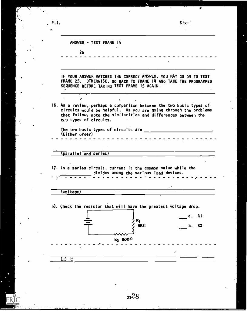
16. As a review, perhaps a comparison between the two basic types ofcircuits would be helpful. As you are going through the problemsthat follow, note the similarities and differences between theti ..1 types of circuits.
The two basic types of circuits are(Either order)
(parallel and series)
17. In a series circuit, current 12 the common value while thedivides among the various load devices.
(voltage)
18. Check the resistor that will have the greatest voltage drop.
a.
b.
RI
R2SKit
vsAn/v--1
ItR slip 0
(a) RI
2128
P.I. Six -I
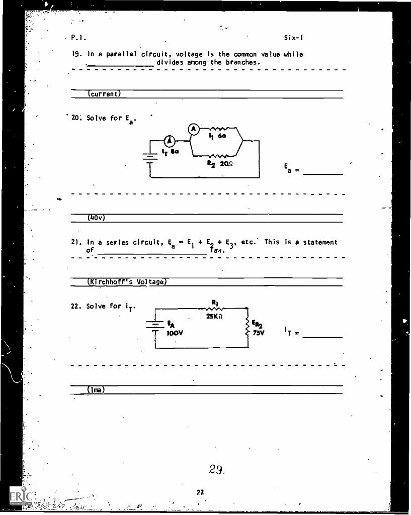
19. In a parallel circuit, voltage Is the common value whiledivides among the branches.
MM.
(current)
20. Solve for Ea.
E.
21. In a series circuit, Ea
E1
E E3, etc. This Is a statementof 'aw. 3'
(Kirchhoff's Voltage)
22. Solve for IT.Ri
-.1-- 2510ER2
I
T =T 100V
22
29.
P.I. Six-I
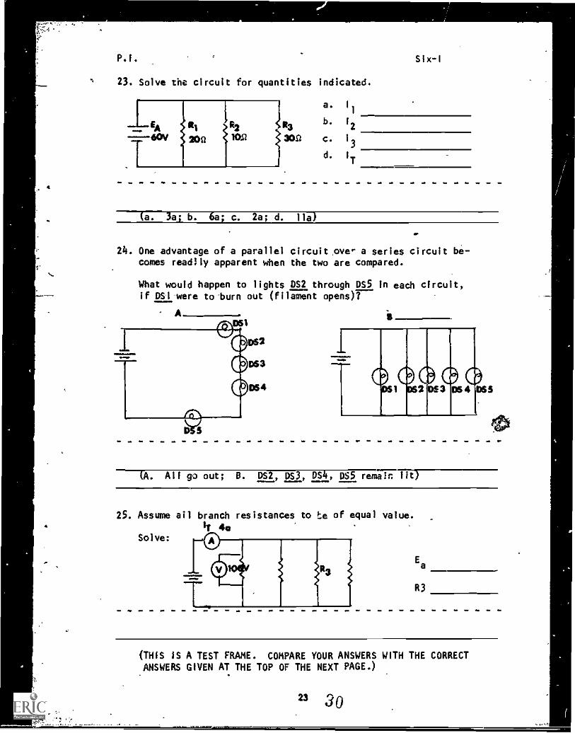
23. Solve the circuit for quantities indicated.
13
3011
a. I
1
b. 12
c. 1
3
d. 1
T
a. 3a1 b. 6a; c. 2a; d. 11a)
24. One advantage of a parallel circuit,over a series circuit be-comes readily apparent when the two are compared.
What would happen to lights DS2 through DS5 in each circuit,if DS1-were to burn out (filament opens)?
A
D S
.- ,_ 0544111 1
(A. All go out; D. DS2, DS3, DS4, DSS remain 11i)
25. Assume all branch resistances to to of equal value.
lT 441Solve:
Ea
R3
(THIS IS A TEST FRAME. COMPARE YOUR ANSWERS WITH THE CORRECTANSWERS GIVEN AT THE TOP OF THE NEXT PAGE.)
23 30
P.I. Six-I
ANSWERS 7 TEST FRAME 25
Ea
= 100v
R3 1000
IF ANY OF YOUR ANSWERS ARE INCORRECT, GO BACK TO FRAME 16 AND TAKETHE PROGRAMMED SEQUENCE.
IF YOUR ANSWERS ARE CORRECT, YOU MAY TAKE THE PROGRESS CHECK,OR YOU MAY STUDY ANY OF THE OTHER RESOURCES LISTEO. IF YOU
TAKE THE PROGRESS CHECK AND ANSWER ALL THE QUESTIONS COR-RECTLY, GO ON TO THE NEXT LESSON. IF NOT, STUOY ANY METHODOF INSTRUCTION YOU WISH UNTIL YOU CAN ANSWER ALL THE QUES-TIONS- CORRECTL -Y -.
,
Summary Six-1
SUMMARYLESSON 1
Rules for Voltage and Current
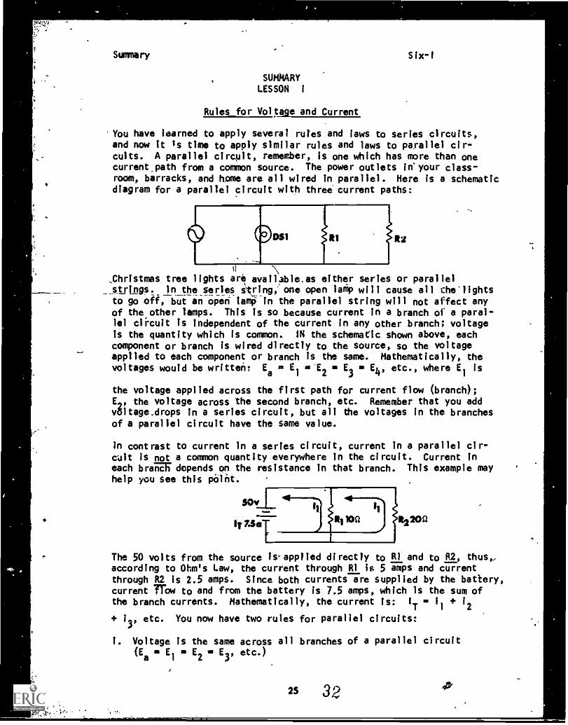
You have learned to apply several rules and laws to series circuits,and now It is time to apply similar rules and laws to parallel cir-cuits. A parallel circuit, remember, is one which has more than onecurrent.path from a common source. The power outlets in'your class-room, barracks, and home are all wired in parallel. Here is a schematicdiagram for a parallel circuit with three current paths:
051 R1 R2
.\
_Christmas tree lights are available.as either series or parallel_,strings. In the series siring,' one open lamp will cause all che'lightsto go off, but an open tamp in the parallel string will not affect anyof the other lamps. This is so because current in a branch of a paral-lel circuit is independent of the current in any other branch; voltageis the quantity which is common. IN the schematic shown above, eachcomponent or branch is wired directly to the source, so the voltageapplied to each component or branch is the same. Mathematically, thevoltages would be written: Ea = El = E2 n E3 = E4, etc., where El is
the voltage applied across the first path for current flow (branch);El, the voltage across the second branch, etc. Remember that you addv81tage.drops in a series circuit, but all the voltages in the branchesof a parallel circuit have the same value.
in contrast to current in a series circuit, current in a parallel cir-c4it is not a common quantity everywhere in the circuit. Current ineach brand depends on the resistance in that branch. This example mayhelp you see this point.
50v
ly 7.50R110Q 112200
The 50 volts from the source Is-applied directly to RI and to R2, thus,,according to Ohm's Law, the current through R1 is 5 amps and currentthrough R2 is 2.5 amps. Since both currents are supplied by the battery,current }'haw to and from the battery is 7.5 amps, which is the sum ofthe branch currents. Mathematically, the current is: IT = 1
1
+ 12
+ 13'
etc. You now have two rules for parallel circuits:
i. Voltage is the same across all branches of a parallel circuit(Ea = El = E2 = E3, etc.)
25 32 45`
Summary Six-1
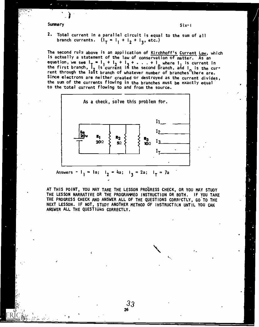
2. Total current in a parallel circuit is equal to the sum of allbranch currents. (IT = 1
I1
21
3'etc.)
The second rutes above is an application of Kirchhoff's Current Law, whichIs actually a statement of the law of conservation of matter. As anequation, We see I 0 12 I . I where I is current inthe first branch, 19 is current id the second Branch, and In is the cur-rent through the last branch of whatever number of branches there are.Since electrons are neither created or destroyed as the current divides,the sum of the currents flowing in the branches must be exactly equalto the total current flowing to and from the source.
As a check, solve this problem for.
Answers - 1
1= la; 1
2 '
= 4a. 1
32a;= 2a. 1
T= 7a
AT THIS POINT, YOU MAY TAKE THE LESSON PROGRESS CHECK, OR YOU MAY STUDYTHE LESSON NARRATIVE DR THE PROGRAMMED INSTRUCTION OR BOTH. IF YOU TAKETHE PROGRESS CHECK AND ANSWER ALL OF THE QUESTIONS COMPCTLY, GO TO THENEXT LESSON. IF NOT, STUDY ANOTHER METHOD OF INSTRUCT1CN UNTIL YOU CANANSWER ALL THE QUESTIOid CORRECTLY.
Y.
3326
/
BASIC ELECTRICITY ANDELECTRON1CS
INDIVIDUALIZED LEARNING SYSTEM
. .-:...:44-t......
MODULE S-I XLESSON II
Rules for Resistance and Power
Study Booklet
27 34
Overview Six-II
OVERVIEW
LESSON II
Rules for Resistance and Power
In this lesson you will study and learn about the following:
4
a
-determining branch resistance
-equivalent resistance
- effect of adding resistor*
- configurations
-methods of solution for equivalent
resistance
- power
- practi-cal app:Ication
Each-of the above topics will be discussed in the order listed.
As you proceed through this lesson, observe and follow direCtions
carefully.
BEFORE YOU START THIS LESSON, PREVIEW THE LIST OF STUDY RESOURCES
ON THE NEXT PAGE.
28
35
Study Resources Six-II
LIST OF STUDY RESOURCES
LESSON Il
Rules for4Resistence and Power
.Tolearnthe material in this lesson, you have the option of choosing,
according to your experience and preferences, any or aileof the foilpwing:
STUDY BOOKLET:
Lesson Narrative
Programmed Instruction
Lesson Summary
ENRICHMENT MATERIAL:
NAVPERS 93400A-la "Basic Electricity, Direct Current."
Fundamentals of Electronics. Buriaq of Natal Personnel.
Washington, D.C.: U.S. Government Printing Office, 1965.
NAVPERS 93492-7 "Prep Text."
Mathematics Series, Volume 2. Bureau of Nava' Personnel.
Washington, D.C.: U.S Government.Printing Office, 1965.
YOU MAY NOW STUDY ANY OR ALL OF THE RESOURCES LISTED ABOVE. YOU MAY
TAKE THE PROGRESS CHECK AT ANY TIME.
2,
Narrative
MARIIATIVE
LESSON II
SixII
Rules for Resistance and Power
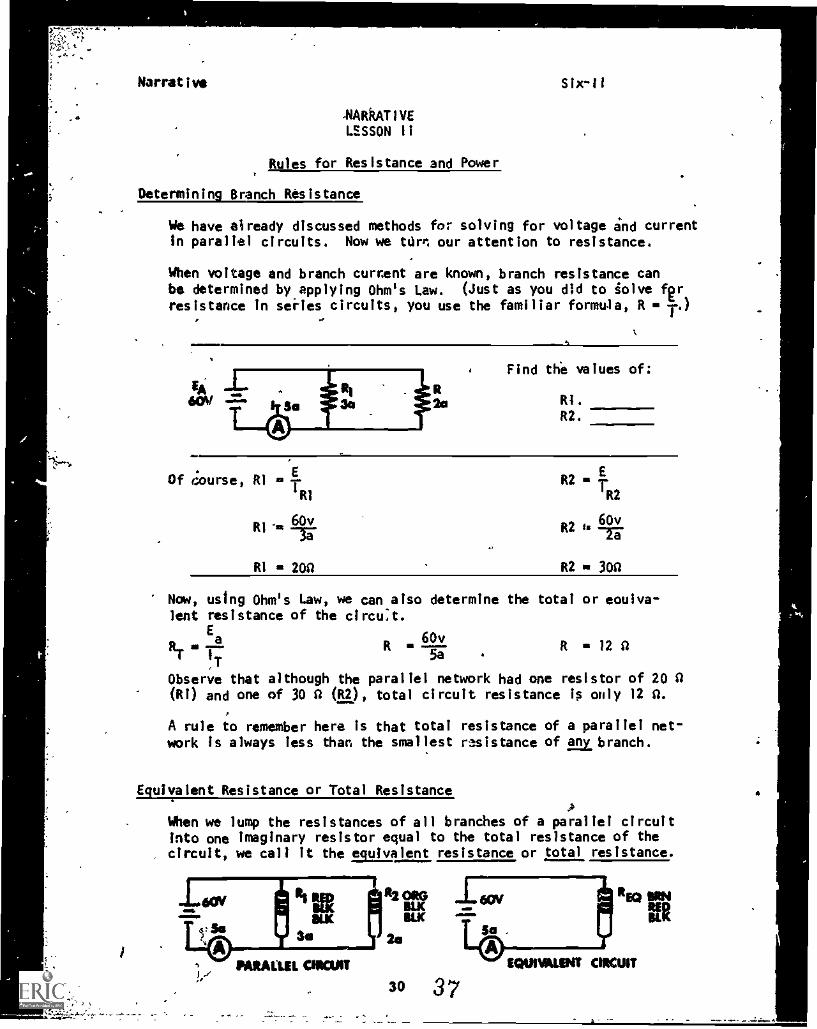
Determining Branch Resistance
We have already discussed methods for solving for voltage and currentin parallel circuits. Now we turn our attention to resistance.
When voltage and branch current are known, branch resistance canbe determined by applying Ohm's Law. (Just as you did to solve fprresistance in series circuits, you use the familiar formula, R = 10
Find the values of:
RI.
R2.
Of course, RI *
60vRI 'IR lir
RI * 200
R2 * 1-
PR2
R260v-17
R2 * 300
Now, using Ohm's Law, we can also determine the total or enuiva-lent resistance of the circuit.
Ea
R60v
R 12 ART 5a
Observe that although the parallel network had one resistor of 20 A(R1) and one of 30 A (R2), total circuit resistance is only 12 A.
A rule to remember here is that total resistance of a parallel net-work Is always less than the smallest resistance of pm:branch.
Equivalent Resistance or Total ResistanceA
When we lump the resistances of all branches of a parallel circuitinto one imaginary resistor equal to the total resistance of thecircuit, we call it the equivalent resistance or total resistance.
MAUL CROAT EQUIVALINT CIRCUIT
30 3 7
REDKIL
Narrative Six-11
The totCil resistance of resistors in parallel is also referred toas EQUIVALENT RESISTANCE. In many texts the terms total resistance(RT) and equivalent resistance (R
eq) are used interchangeably,.
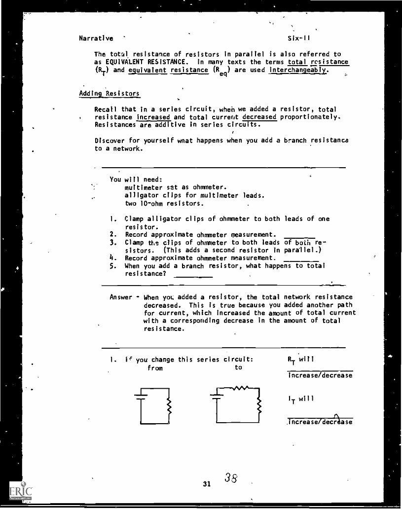
Adding_ Resistors
Recall that In a series circuit, when we added a resistor, total. resistance increased and total current decreased proportionately.
Resistances-Vi-ITElive in series circiTi ts
Discover for yourself wnat happens when you add a branch resistanceto a network.
You will need:multimeter set as ohmmeter.alligator clips for multimeter leads.two 10-ohm resistors.
1. Clamp alligator clips of ohmmeter to both leads of oneresistor.
2. Record approximate ohmmeter measurement.
3. Clamp the clips of ohmmeter to both leads of both re-sistors. (This adds a second resistor in parallel.)
4. Record approximate ohmmeter measurement.5. When you add a branch resistor, what happens to total
resistance?
Answer - When yon; added a resistor, the total network resistance
decreased. This is true because you added another pathfor current, which increased the amount of total currentwith a corresponding decrease in the amount of totalresistance.
1. IE you change this series circuit:from to
ri3
31 38
RT
will
increase/decrease
I
Twill
.increase /decrease
Air
to
'
e ,f -
Narrative
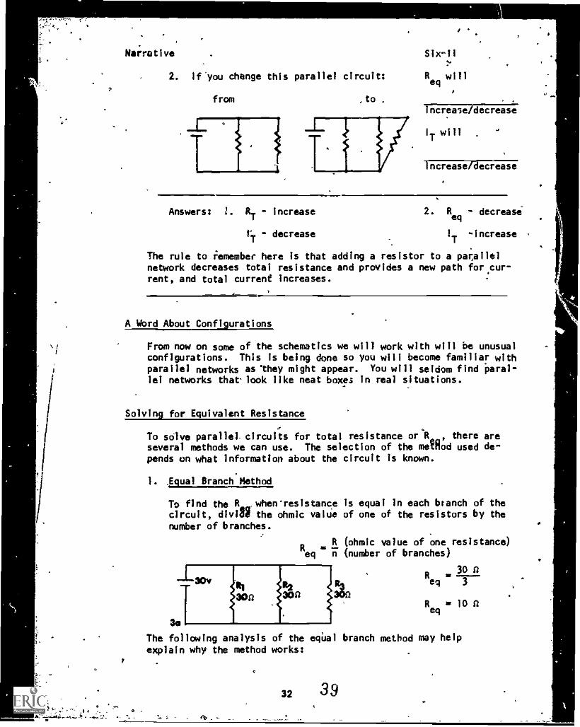
2. If'you change this parallel circuit:
from to .
Tiai7Odecrease
IT will
Answers: RT - increase
tY - decrease
increase/decrease
2. Req
- decrease
I
T-Increase
The rule to remember here is that adding a resistor to a parAlleinetwork decreases total resistance and provides a new path for.cur-rent, and total current increases.
A Word About Configurations
From now on some of the schematics we will work with will be unusualconfigurations. This is being done so you will become familiar withparallel networks as 'they might appear. You will seldom find Paral-lel networks that-look like neat boxes in real situations.
Solving for Equivalent Resistance
To solve parallel. circuits for total resistance or4R,.., there areseveral methods we can use. The selection of the method used de-pends on what information about the circuit Is known.
). Equal Branch Method
To find the R. whervresistancecircuit, diviBi the ohmic valuenumber of branches.
Req n
Is equal in each branch of theof one of the resistors by the
(ohmic value of one resistance)(number of branches)
3e
The following analysis of the eqUal branch method may help
explain why the method works:
R30 n
eq 3
Req
la 10 n
32 39
ta
P.1. . Six-11
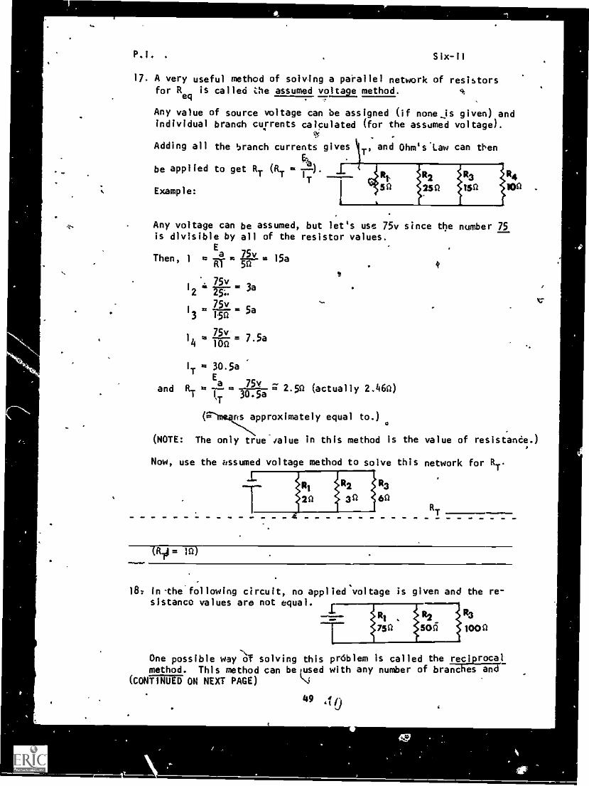
17. A very useful method of solving a parallel network of resistorsfor R
eqis called the assumed voltage method.
Any value of source voltage can be assigned (if none is given) andindividual branch currents calculated (for the assumed voltage).
Adding all the branch currents gives , and Ohm's'Law can then
be applied to get RT (RTT
Example:
R4
100 .
Any voltage can be assumed, but let's use 75v since the number 75is divisible by all of the resistor values.
Then, 1 R
75vI 41 lig 3a2 25'.
75vI TA 5a3 1.50
75v
14 ft Toii 7'5a
1T 30.5a
a 75v 2 c,'T
'T30.5a
and (actually 2.160)
us approximately equal to.)
(NOTE: The only true-ialue in this method is the value of resistance.)
Now, use the assumed voltage method to solve this network for RT.
R3
6CRT
= )n)
18: In-the following circuit, no appliedsvoltage is given and the re-sistance values are not equal.
One possible way -Of solving this prdblem is called the reciprocalmethod. This method can be used with any number of branches and
(CONTINUED ON NEXT PAGE)
49 tto
12.1. Six-11
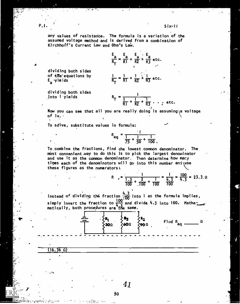
any values of resistance. The formula is a variation of theassumed voltage method-and is derived from a combination ofKirchhoff's Current Law and Ohm's La4.
Ea Ea Ea Ea
etc.
ART R1 R2
dividing both sidesof tWe'equations byEalie;ds
dividing both sidesinto 1 yields
1 1 1....17.4.n.+ri etc.
RTRif
+ITT etc.
Now you can see that all you are really doing is assuming,a voltageof iv.
To sdlve, substitute values in formula:
Req 1 1 1
75 50 100.
To.combine the fractions, find the lowest common denominator. Themost convenient.way to do this is to pick the largest denominatorand use it as the common denominator. Then determine how manytimes each of the denominators will go into this number andrethese figures as the numerators:
1
R1
1 10013 1.3 2 1
-473. 211 473' " j II
.Tar + Tar WO.
4.3Instead of dividing th6 fraction ...my into 1 as the formula implies,
100simply invert the fraction to 1-1- and divide 4.3 into 100. Mathe-matically, both procedures are the same.
(16.3; a)
Find Req
41tO
,..., %.
,
1*
S
P.I; Six-II
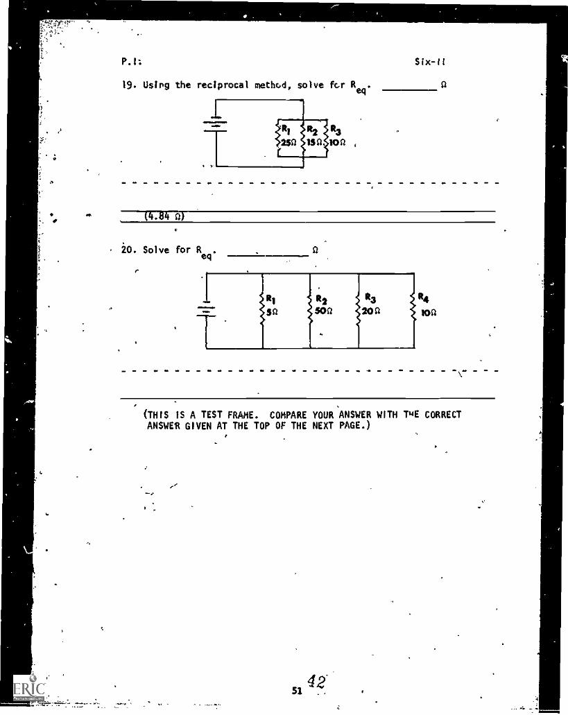
19. Usipg the reciprocal method, solve fcr Req
.
*..., (4.84 0)
,
c
0
{
a
t
20. Solve for Req
.
r
lt4toa
0 ..
(THIS IS A TEST FRAME. COMPARE YOUR ANSWER WITH PIE CORRECTANSWER GIVEN AT THE TOP OF THE NEXT PAGE.)
0
, . .
42... ---..
P.I. Six-II
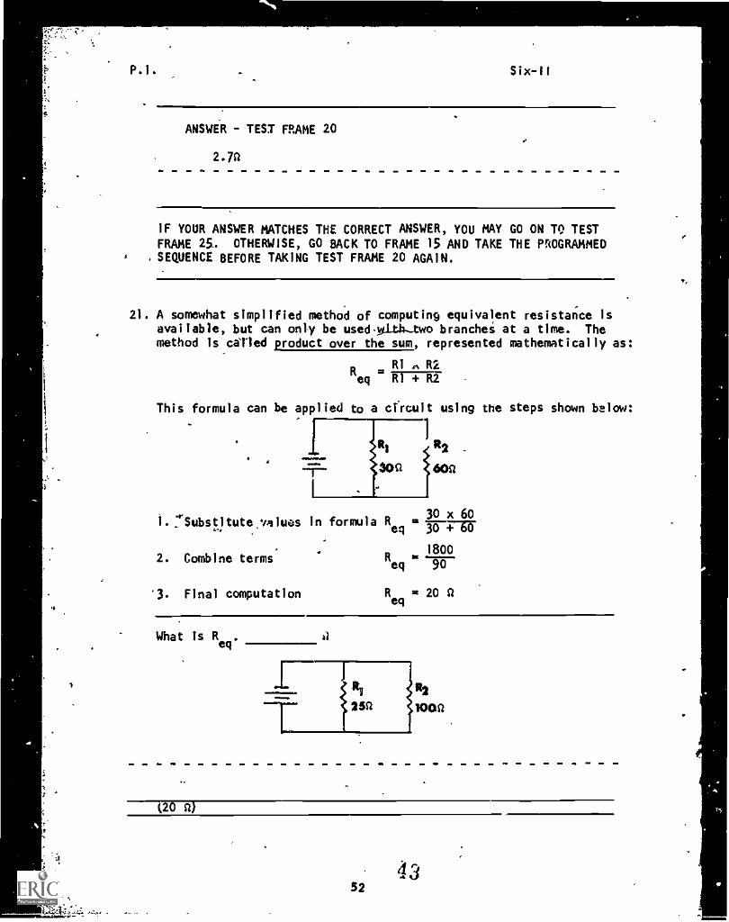
ANSWER - TEST FRAME 20
2.7a
IF YOUR ANSWER MATCHES THE CORRECT ANSWER, YOU MAY GO ON TO TESTFRAME 25.. OTHERWISE, GO BACK TO FRAME 15 AND TAKE THE PROGRAMMEDSEQUENCE BEFORE TAKING TEST FRAME 20 AGAIN.
21. A somewhat simplified method of computing equivalent resistance isavailable, but can only be usedwithtwo branches at a time. Themethod is castled product over the sum, represented mathematically as:
RI R2Req
This formula can be applied to a cfrcuit using the steps shown below:
R2
60Q
30 x 601.:rSubstitute,values in formula Reg = 1-6-47-61-
2. Combine terms
'3. Final computation
1800R ----eq 90
Reg
= 20 a
What is Reg
R2
100$1
(20a)
52
Six-II
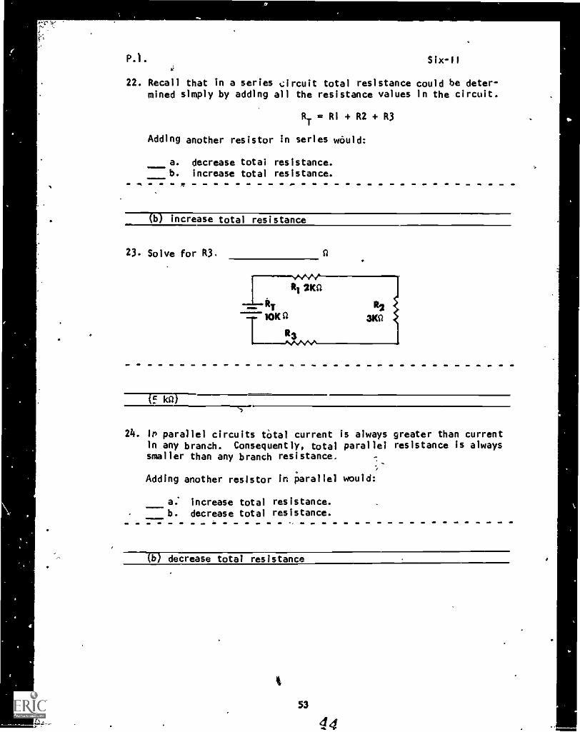
22. Recall that in a series Orcuit total resistance could be deter-mined simply by adding all the resistance values in the circuit.
RT = R1 + R2 + R3
Adding another resistor in series would:
a. decrease total resistance.b. increase total resistance.
- - - -
( b )
v ..
. (b) increase total resistance
23. Solve for R3.
WslY
410Ka44 R2
R
30
R1 20
if MI)
24. iP parallel circuits total current is always greater than currentin any branch. Consequently, total parallel resistance is alwayssmaller than any branch resistance.
.7..
.
Adding another resistor in parallel would:
a: increase total resistance.b. decrease total resistance.
(b) decrease total resistance
P.1. Six-II
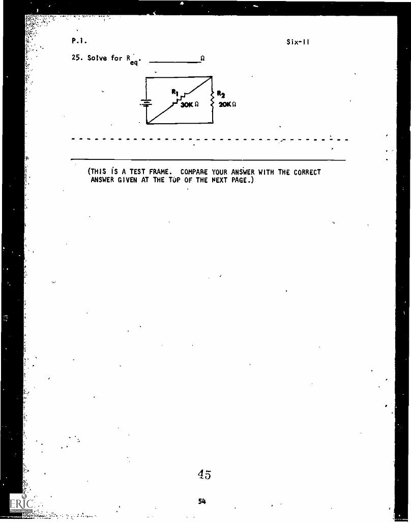
25. Solve for Req.
0
R2
20K 0
(THIS IS A TEST FRAME. COMPARE YOUR ANSWER WITH THE CORRECTANSWER GIVEN AT THE TOP OF THE NEXT PAGE.)
45
54
P.I. Six-II
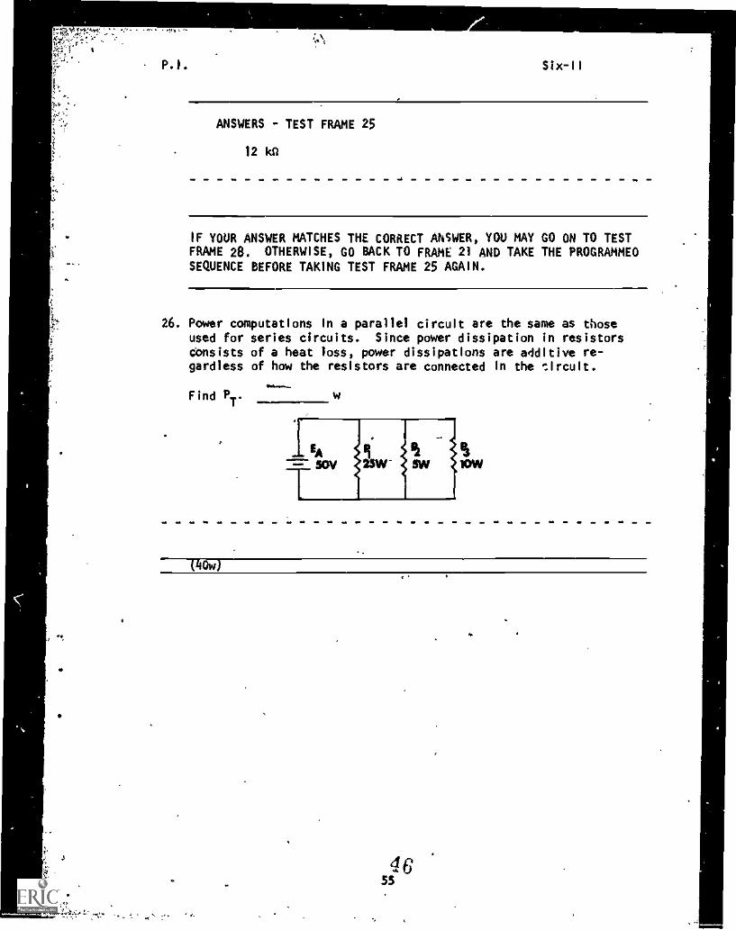
ANSWERS TEST FRAME 25
12 Ica
IF YOUR ANSWER MATCHES THE CORRECT ANSWER, YOU MAY GO ON TO TESTFRAME 28. OTHERWISE, GO BACK TO FRAME 21 AND TAKE THE PROGRAMMEDSEQUENCE BEFORE TAKING TEST FRAME 25 AGAIN.
26. Power computations in a parallel circuit are the same as thoseused for series circuits. Since power dissipation in resistorsconsists of a heat loss, power dissipations are additive re-gardless of how the resistors are connected in the thcult.
Find PT
w
(110w)
46SS
P.1. Six-I1
E2
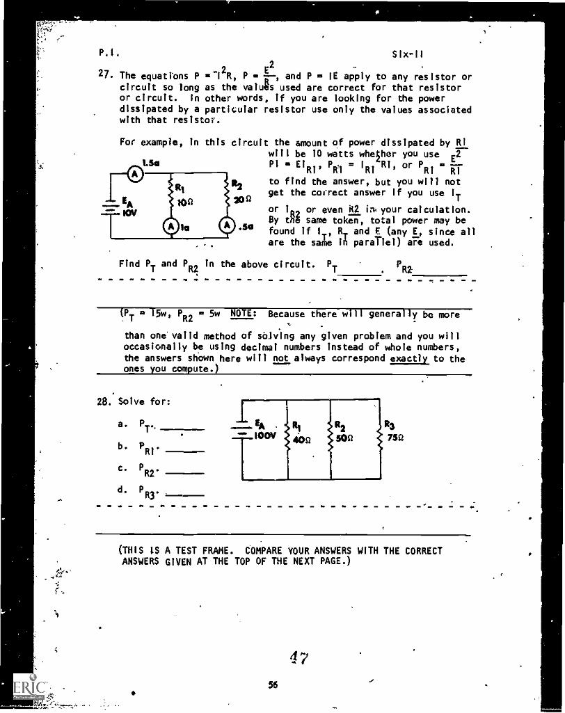
27. The equations P2R, P a and P a IE apply to any resistor or
circuit so long as the valu8s used are correct for that resistoror circuit. In other words, if you are looking for the powerdissipated by a particular resistor use only the values associatedwith that resistor.
For example, in this circuit the amount of power dissipated by RIwill be 10 watts whether you use E2
1.5e P1 ElR1' I
a I
RiRi
'
or P ---Ri Ri
to find the answer, but you will notget the correct answer If you use IT
or 100 or even it2 in. your calculation.By thl same token, total power may befound if 1,, R, and E (any E, since all
.are the sale in parallel) are used.
Find PT
and PIt;
in the above circuit. PT . la
PT
15w, PR2
a 5w NOTE: Because there will generally be more
than one valid method of sblving any given problem and you willoccasionally be using decimal numbers instead of whole numbers,the answers shown here will not always correspond exactly to theones you compute.)
28. Solve for:
a. PT..
b. PRI.
c. PR2
d. PR3.
R3
750
(THIS IS A TEST FRAME. COMPARE YOUR ANSWERS WITH THE CORRECTANSWERS GIVEN AT THE TOP OF THE NEXT PAGE.)
56
Qr
f
P.I. Six-II
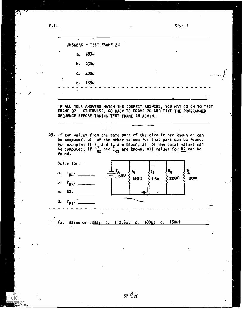
ANSWERS - TEST ,FRAME 28
a. 583w
b. 250w
c. 200w
d. 133w
IF ALL YOUR ANSWERS MATCH THE CORRECT ANSWERS, YOU MAY GO ON TO TESTFRAME 32. OTHERWISE, GO BACK TO FRAME 26 AND TAKE THE PROGRAMMEDSEQUENCE BEFORE TAKING TEST FRAME 28 AGAIN.
29. If twc values from the same part of the circuit are known or canbe computed, all of the other values for that part can be found.Dor example; if E and 11. are known, all of the total values canbe computed; if 112 and E are known, all values for R2 can be
R2found.
Solve for:
a. 1R4
b. P .
R3-------
c. R2.
d. PR1
.r
(a. 333ma or .33a; b. 112.5w; c. 100D; d. 150w)
57 48
P.I.
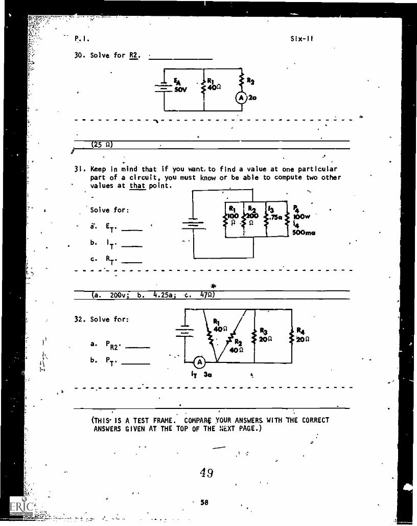
30. Solve for R2.
Six-11
(25 0)
31. Keep in mind that if you want, to find a value at one particularpart of a circuit, you must know or be able to compute two othervalues at that point.
Solve for:
a. ET.
b. IT.
C.RT.
..a. 200v; b. .25ai c.
32. Solve for:
a. PR2 .
b. PT
.
36
(THIS' IS A TEST FRAME. COMPARg YOUR ANSWERS WITH THE CORRECTANSWERS GIVEN AT THE TOP OF THE NEXT PAGE.)
r
.'^'
49
58
lav
A
.0
P .1 .
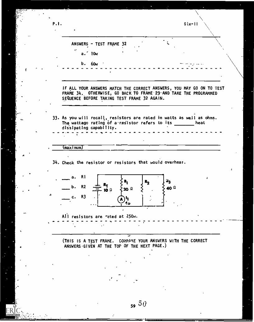
ANSWERS - TEST FRAME 32
a.' lOw
b. 60w
IF ALL YOUR ANSWERS MATCH THE CORRECT ANSWERS, YOU MAY GO ON TO TESTFRAME 34. OTHERWISE, GO BACK TO FRAME 29 AND TAKE THE PROGRAMMEDSEQUENCE BEFORE TAKING TEST FRAME 32 AGAIN.
33. As you will recall, resistors are rated in watts as well as ohms.The wattage rating Of araiistor refers to its heat
diisipating capability.
(maximum)
34. Check the resistor or resistors that would overhear.
a. R1
b. R2.NT
ioc. R3 .
Al) resistors are rated at 290w.
FIS
;23
40n
at
(THIS IS A TEST FRAME. COHPARE YOUR ANSWERS WITH THE CORRECT
ANSWERS GIVEN AT THE TOP OF THE NEXT PAGE.)
P.I. Six -II
ANSWER - TEST FRAME 34
a. RI
IF YOUR ANSWER IS INCORRECT, GO BACK TO FRAME 33 AND TAKE THEPROGRAMMED SEQUENCE.
IF YOUR ANSWER IS CORRECT, YOU MAY TAKE THE PROGRESS CHECK, OR YOU MAYSTUDY ANY OF THE OTHER RESOURCES LISTED. IF'YOU TAKE THE PROGRESS CHECKAND ANSWER ALL THE QUESTIONS CORRECTLY, GO ON TO THE NEXT LESSON. IF.NOT,
STUDY ANY METHOD OF INSTRUCTION YOU WISH UNTIL YOU CAN ANSWER ALL THEQUESTIONS CORRECTLY.
51
0111
Summary
SUMMARY
LFSSON II
Rules for Resistance and Power
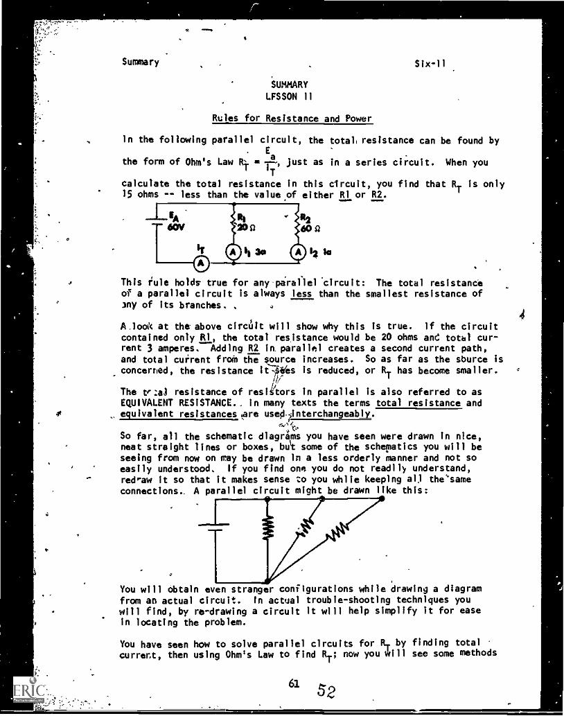
In the following parallel circuit, the total, resistance can be found byE
the form of Ohm's Law RT 121 just as in a series circuit. When youT
calculate the total resistance in this circuit, you find that RT is only15 ohms -- less than the value of either Ri or R2.
R260g
12
This rule holds true for any-piraflel 'circuit: The total resistanceof a parallel circuit is always less than the smallest resistance ofmy of its branches.
',look at the above circuit will show why this is true. If the circuitcontained only R1, the total resistance would be 20 ohms and total cur-rent 3 amperes. Adding R2 in. parallel creates a second current path,and total current froil the source increases. So as far as the source isconcerned, the resistance it -Wes is reduced, or RT has become smaller.
/1(
The trua resistance of reslh'tors In parallel is also referred to asEQUIVALENT RESISTANCE.. In many texts the terms total resistance andequivalent resistances; re used.linterchangeably.
So far, all the schematic diagrams you have seen were drawn in nice,neat straight lines or boxes, bust some of the schematics you will beseeing from now on may be drawn in a less orderly manner and not soeasily understood. If you find one you do not readily understand,redraw it so that it makes sense to you while keeping all the'sameconnections.. A parallel circuit might be drawn like this:
You will obtain even stranger configurations while drawing a diagramfrom an actual circuit. In actual trouble-shooting techniques youwill find, by re-drawing a circuit it will help simplify It for easein locating the problem.
You have seen how to solve parallel circuits for RT by finding totalcurrent, then using Ohm's Law to find RT; now you will see some methods
" 52
Summary Six-11 _ .
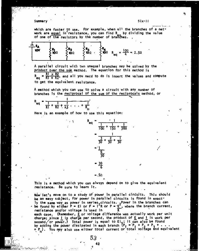
which are faster_ o use. For example, when all the branches of a net-work are equal in resistance, you can find R by dividing the valueof one of the resistors by the number of braUhes.
1_4 140 lt io2 iRja IOSt Req = m 2.50
A parallel circuit with two unequal branches may be solved by theproduct cwertho sdm method. The equation for this method is
R1 x R2Req
= 11-717, and all you need to do is insert the values and compute
to get the equivalent resistance.
A method which you can use to solve a circuit with any number ofbranches is the reciprocal of the sum of the reciprocals method, or
Req nI. i 1 i
ilt 4. II t.e3.
+ III'n. .7.
Hese is an example of how to use this equation:
s R m
eq /
11
1
150 300
1
2 1
30-' 3r)
30
= 30 4
=.5A0
This is a method which you can always depend on to give the equivalentresistance. Be sure to learn it.
NOwslet's move on to a study of power in parallel circuits. This shouldbe an easy subject, for power in parallel circuits Is found in exact-
ly the same way as power in serieslcircuits. 2Power in the branches canbe found by either P I. El or = l'R or P , where the branch current,
resistance and/or voltage ls"used ineach case. (Remember, E or voltage difference wasectually work per unitchargeLsince i 4 charge per second, the product of E and I is work per
second/or power.) Total power is equal to EIT; it can also be foundby adding the power dissipated in each branch IPT =1), + P2 + P2 + . . .
+ P.). You may also use eitner total current or total voltage dnd equivalent.11
e: .1'- t _
62
aL)
Summary Six-IIa E
T2
resistance in PT = IT x Reg or PT - R . You ran prove any of these by
making your own parallel circuit and working out the values by allthese methods.. All of you? answers should agree.
AT THIS POI NI, YOU MAY.TAKE THE LESSON PROJ3 SS CHECK, OR YOU MAY STUDYTHE LESSON ORRATIVE OR THE PROGRAMED INSTRUCTION OR BOTH. IF YOU TAKETHE PROGRESS.CHECK AND ANSWER ALL OF THE QUESTIONS CORRECTLY, GO TO THE
. NEXT LESSON. IF NOT, STUDY'ANOTHER METHOD OF INSTRUCTION UNTIL YOU CANANSWER ALL THE QUESTIONS CORRECTLY.
5463
R.
1
VI
Tag ,,witches bvfore rnaking repato,--k
BASIC ELECTRICITY AND ELECTRONICS
INDIVIDUALIZED LEARNING SYSTEM
MODULE SIXLESSON I I I
Variational Analysis
Study Booklet
65 56
4
V R.
.overview
OVERVIEW
LESSON III
Variational Analysis
In this lesson you will study and learn about the following:
i
.
1, o
-variable quantities
-changiAg voltage
-adding or removing a parallel
resistor
-changing resistance in an existing
bramh
BEFORE YOU START THIS LESSON, PREVIEW THE LIST OF STUDY RESOURCES
ON THE NEXT PAGE,
t
,
/
57
66
. .
. s
Study Resources Six-111
LIST OF STUDY RESOURCES
LESSON 111
Variational Analysis
To learn the material in this lesson, you have the option of choosing,
wording to your experience and preferences, any or all of the follow-
ing
STUDY BOOKLET:
Lesson Narrative
'Programmed Instruction
Lesson Suimary
ENRICHMENT MATERIAL:
WAVERS 93400A-1a "Basic Electricity, Direct Current."
Fundamentals of Electronics. Bureau of. Naval Personnel.
Washington, D.C.: U.S. Government Printing Office, 1965.
YOU MAY NOW STUDY ANY OR ALL OF TIDE RESOURCES LISTED ABOVE: 'YOU MAY
TAKE THE PROGRESS CHECK AT ANY TIME.
a
Narrative
NARRATIVELESSON I I
Variational Analysis
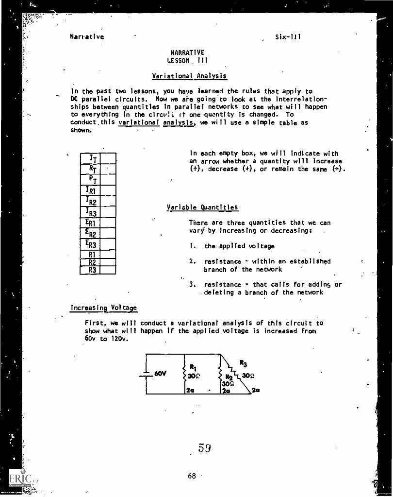
In the past two lessons, you have learned the rules that apply toDC parallel circuits. Now we are going to look at the interrelation-ships between quantities In parallel networks to see what will happento everything in the circOL it one quantity is changed. Toconduct.this variational analysis, we will use a simple table asshown.
In each empty box, we will indicate withan arrow whether a quantity will increase(+), decrease (+) , or remain the same (*).
Variable Quantities
There are three quantities that we canvarfby increasing or decreasing:
I. the applied voltage
2. resistance - within an establishedbranch of the network
resistance - that calls for adding or,deleting a branch of the network
Increasina1taUtte
First, we will conduct a variational analysis of this circuit toshow what will happen if the applied voltage is increased from60v to 120v.
IP
59
68
Narrative
What Happens to Branch Current
Six-111
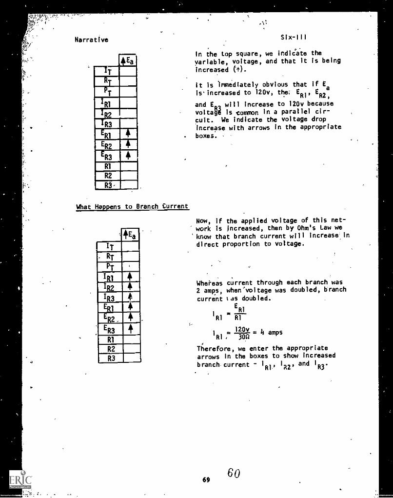
In the top square, we indiCate thevariable, voltage, and that it is being
increased (0.
It is Immediately obvious that if Ea
is' increased to 120v the; E E' RI' R2,
and ER willwill increase to 120v becausevoltage is common in a parallel cir-
cuit. We indicate the voltage dropincrease with arrows in the appropriate
boxes.
Now, if the applied voltage of this net-work is Increased, then by Ohm's Law we
know that branch current will increase.lndirect proportion to voltage.
Whei'eas current through each branch was2 amps, when'voltage was doubled, branchcurrent tas doubled.
ER1
/RI '4 RI
20v/RI ,24
14 amps
Therefore, we enter the appropriatearrows in the boxes to show increased
branch current 1
R1,'1
R2'and 1
R3.
Narrative i
Total Current
What Will Happen To Resistance
Si x- I 1.1
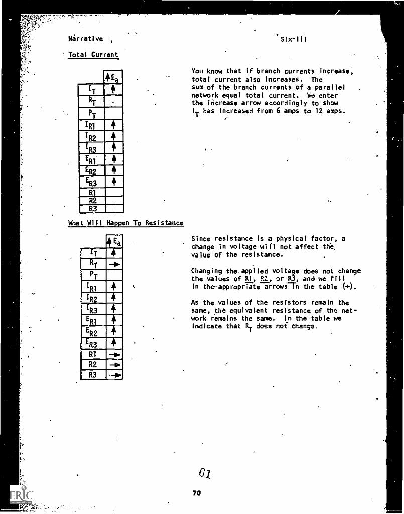
You know that if branch currents increase,total current also increases. Thesum of the branch currents of a parallelnetwork equal total current. We enterthe increase arrow accordingly to showI
Thas Increased from 6 amps to 12 amps.
Since resistance is a physical factor, achange in voltage will not affect thevalue of the resistance.
Changing the, applied voltage does not changethe values of RI, R2, or R3, and we fillin theappropriate arrows-711 the table (4).
As the values of the resistors remain thesame, the equivalent resistance of the net-work remains the same. In the table weIndicate that RT doss noi change.
70
Narrative
What Wilillappen to Total Power
r
Six-111
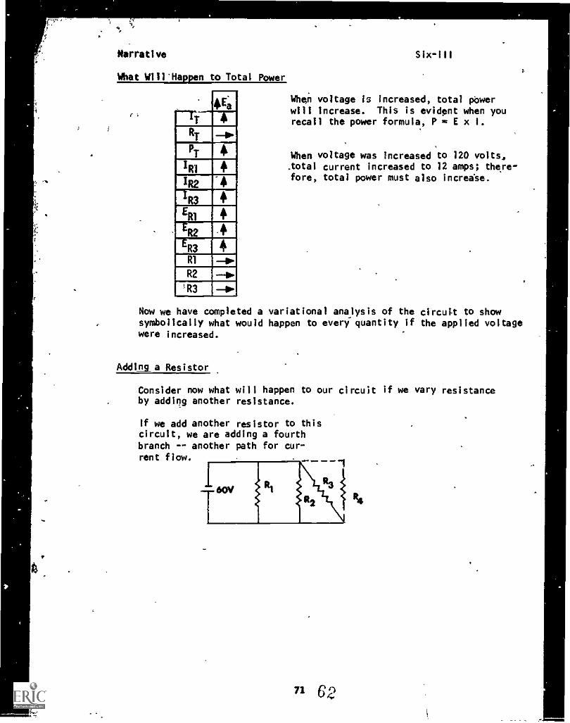
When voltage is increased, total Owerwill increase. This is evident when yourecall the power formula, P = E x I.
When voltage was increased to 120 volts,.total current Increased to 12 amps; there-fore, total power must also increase.
Now we have completed a variational analysis of the circuit to showsymbolically what would happen to every quantity if the applied voltagewere increased.
Adding a Resistor
Consider now what will happen to our circuit if we vary resistanceby adding another resistance.
If we add another resistor to thiscircuit, we are adding a fourthbranch -- another path for cur-rent flow.
71 62
Naerative
-*Effect on Current
What Happens to Voltage
AddR4
ITRT
ET
PT
4
IR11R2 -7111.
1 R3E
R1
ER2
ER3
R1
R2
R3
Six-111
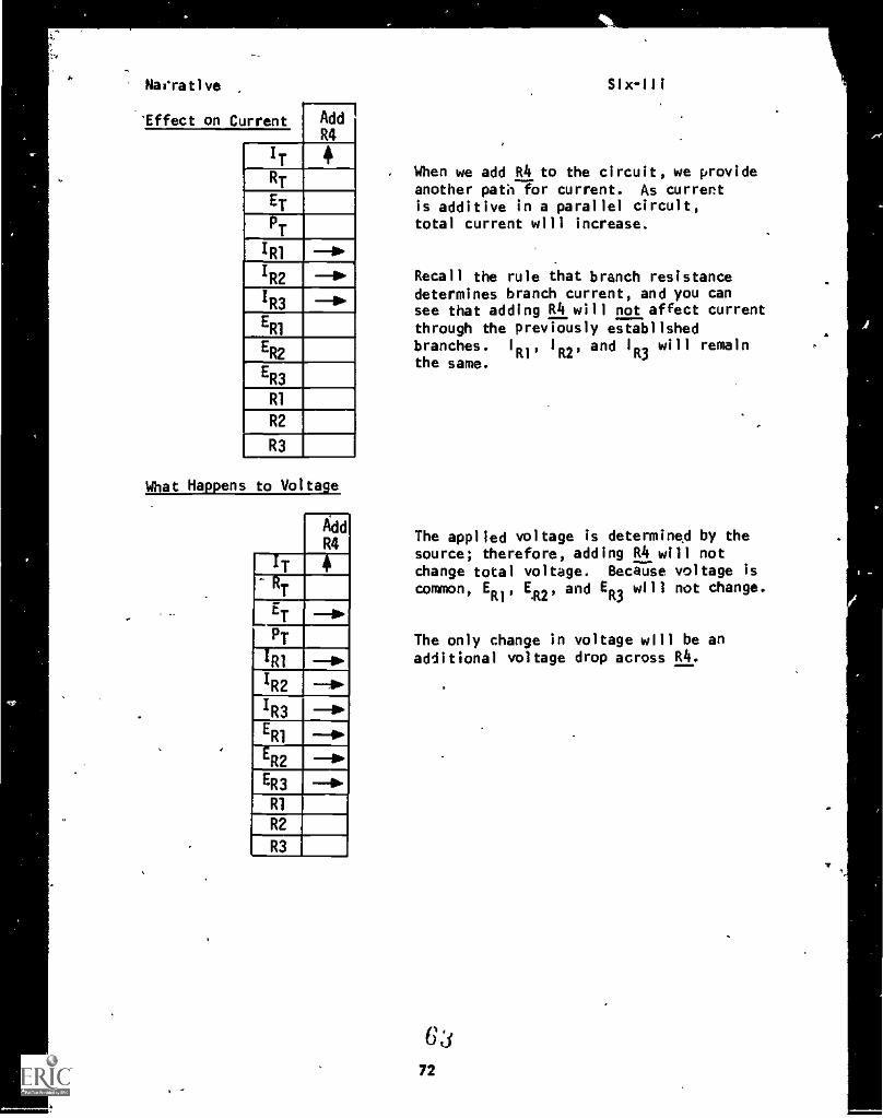
When we add R4 to the circuit, we provideanother path for current. As currentis additive in a parallel circuit,total current will increase.
Recall the rule that branch resistancedetermines branch current, and you cansee that adding R4 will not affect current
through the previously establishedbranches. I
R1'1
R2'and 1
R3will remain
the same.
The applied voltage is determined by thesource; therefore, adding R4 will notChange total voltage. Because voltage iscommon, ER1, ER2, and ER3 will not change.
The only change in voltage will be anadditional voltage drop across R4.
6:1
72
Narrative Six-III
What Happens to Resistance
RT
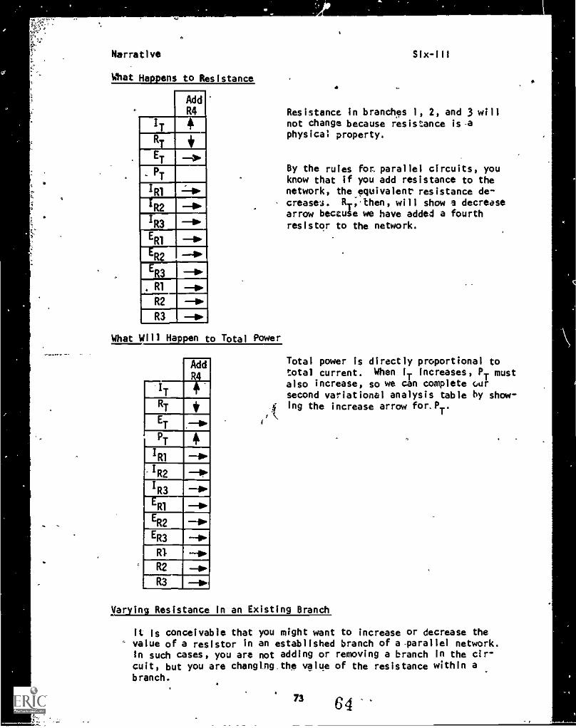
AddR4 Resistance in branches 1, 2, and 3 will
not change because resistance is .aphysical property.
E 11PT
IR1 11Po
1R2
1R3 11Po
R2
R3
R1
R2
R3
By the rules fon parallel circuits, youknow that if you add resistance to thenetwork, the equivalent resistance de-
- creases. Rr,then, will show a decreasearrow beccuie we have added a fourthresistor to the network.
What Will Happen to Total Power
Total power is directly proportional tototal current. When IT increases, PT mustalso increase, so we can complete oarsecond variational analysis table by show-ing the increase arrow for. PT.
t'k
Mar tin Resistance in an Existing Branch
It is conceivable that you might want to increase or decrease thevalue of a resistor in an established branch of a-parallel network.In such cases, you are not adding or removing a branch in the cir-cuit, but you are changtng.the value of the resistance within abranch.
73 64
Narrative Six-Ill
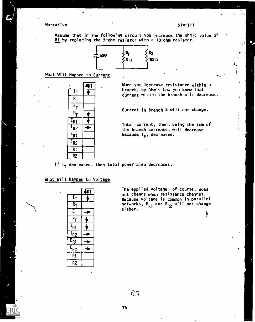
Assume that in the following circuit you increase the ohmic value ofRI by replacing the 5-ohm resistor with a 10-ohm resistor.
12
10g
What Will Happen to Current
4(ti
RT
ET
R2E
R1
ER2
R1
R2
When you increase resistance within abranch, by Ohm's Law you know thatcurrent within the branch will decrease.
Current in Branch 2 will not change.
Total current, then, being the sum ofthe branch currents, will decreasebecause 1p, decreased.
If I
Tdecreases. then total power also decreases.
What Will Happen to'Voltage
The applied voltage, of course, doesnot change when resistance changes.Because voltage is common in parallelnetworks, ER1 and E
R2will not change
either.
65
Narrative
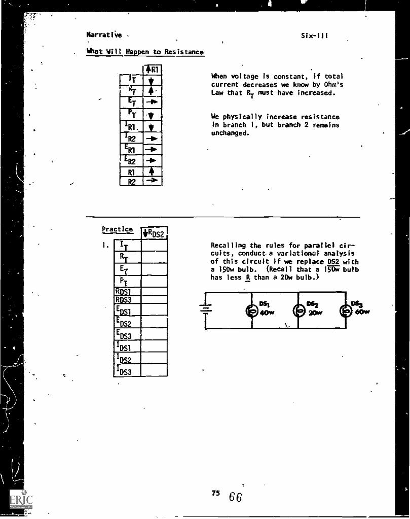
. What Will Alvan to Resistance
RlWhen voltage is constant, if totalcurrent decreases we know by Ohm'sLaw that RT must have increased.
We physically increase resistancein branch I, but branch 2 remainsunchanged.
Recalling the rules for parallel cir-cuits, conducta variational analysisof this circuit if we replace DS2 witha 150w bulb. (Recall that a lni7 bulbhas less R than a 20w bulb.)
75 6 6
Narrative
2. 2
IT
WTET
FT
IRI
R
R3
ERI
ER2
ER3
R1
R2
R3
Six-111
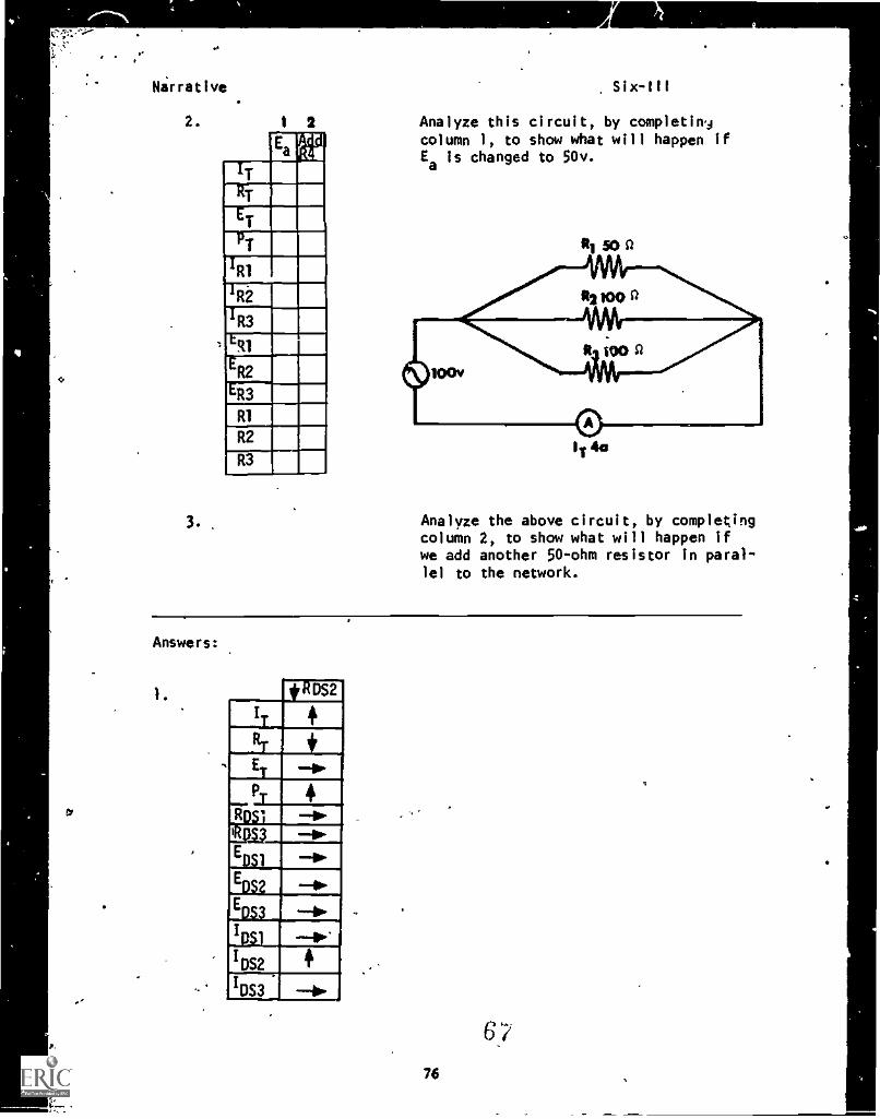
Analyze this circuit, by completimjcolumn 1, to show what will happen ifEa
is changed to 50v.
3. .Analyze the above circuit, by completingcolumn 2, to show what will happen ifwe add another 50ohm resistor in paral-lel to the network.
Answers:
ROS2
:IT
. RT , +ET 411.
r
P 4-Ric -iv-Nu.EDSI
-..
,EDS2 --11.
,
EDS3--b..,
,IDSI --4..
IDS2.
'DS3 --bo
76
Narrative Six-III
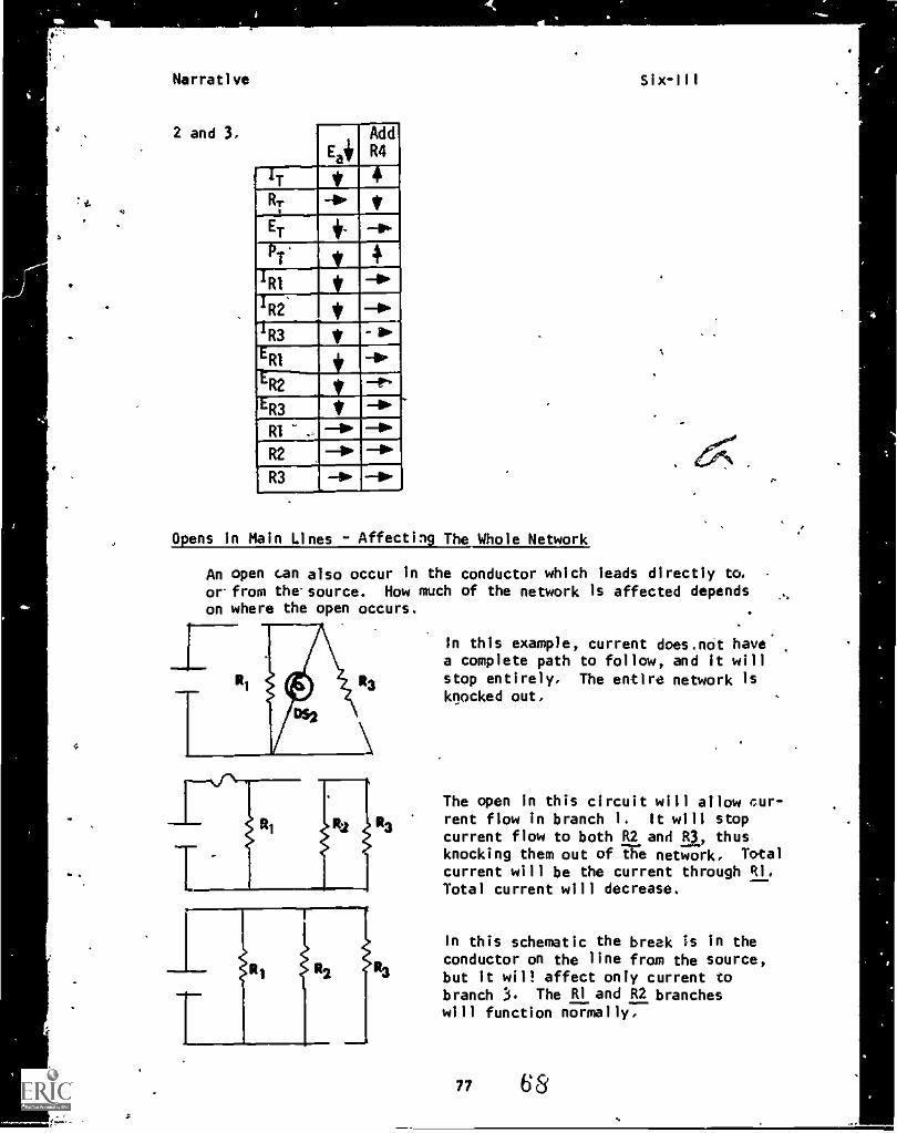
2 and 3. AddE
IT s 4RT -111. *ET 4 ^1P'
S +41 V 11"
'R2 It II'R3 V .1..
ERI i -.11,'
iR2 V t'ER3 * -a
RI .. 1`R2 1` P"R3 -r 0. 110- 4.
0 ens in Main Lines - Affecting The Whole Network
An open can also occur In the conductor which leads directly to.or- from the- source. How much of the network is affected dependson where the open occurs.
In this example, current does.not havea complete path to follow, and it willstop entirely. The entire network isknocked out.
The open in this circuit will allow cur-rent flow in branch 1. It will stopcurrent flow to both R2 and R3, thusknocking them out of the network. Total
current will be the current through RI.Total current will decrease.
In this schematic the break is in theconductor on the line from the source,but it will affect only current tobranch 3. The RI and R2 brancheswill function normally.
"` t7^ ;',
.4a
Hirrathie Six-III
NOW YOU MAY TAKE THE.PROGRESS CHECK, OR YOU MAY STUDY ANY OF THEOTHER RESOURCES LISTED.
7."
,
1.
69
13
44007 -4.4
P.I.
PROGRAMED INSTRUCTIONLESSON III
Variational Analysis
TEST FRAMES A. 8, 12, 20, AND 25. AS BEFORE, GO FIRST TO TESTFRAME 8 AND SEE IF YOU CAN ANSWER ALL THE QUESTIONS THERE. FOLLOWTHE DIRECTIONS GIVEN AFTER THE TEST FRAME.
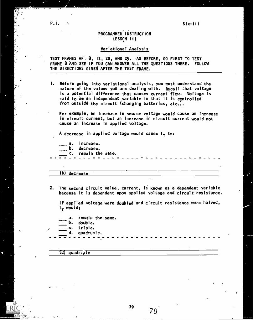
1. Before going into variational analysis, you must understand thenature of the values you are dealing with. Recall that voltageis a potential difference that causes current^flow. Voltage issaid to be an independent variable in that it is controlledfrom outside the circuit (changing batteries, etc.).
For example, an increase in source voltage would cause an increasein circuit current, but an increase in circuit current would notcause an increase in applied voltage.
A decrease in applied voltage would cause IT to:
a. increase.
b. decrease.c. remain the iawe.
(b) decrease
2. The second circuit value, current, is known as a dependent variablebecause it is dependent upon applied voltage and circuit resistance.
If applied voltage were doubled and ercuit resistance were halved,1 T
would;
a. remain the same.b. double.
c. triple.d. quadruple.
(d) quadrt,ple
79
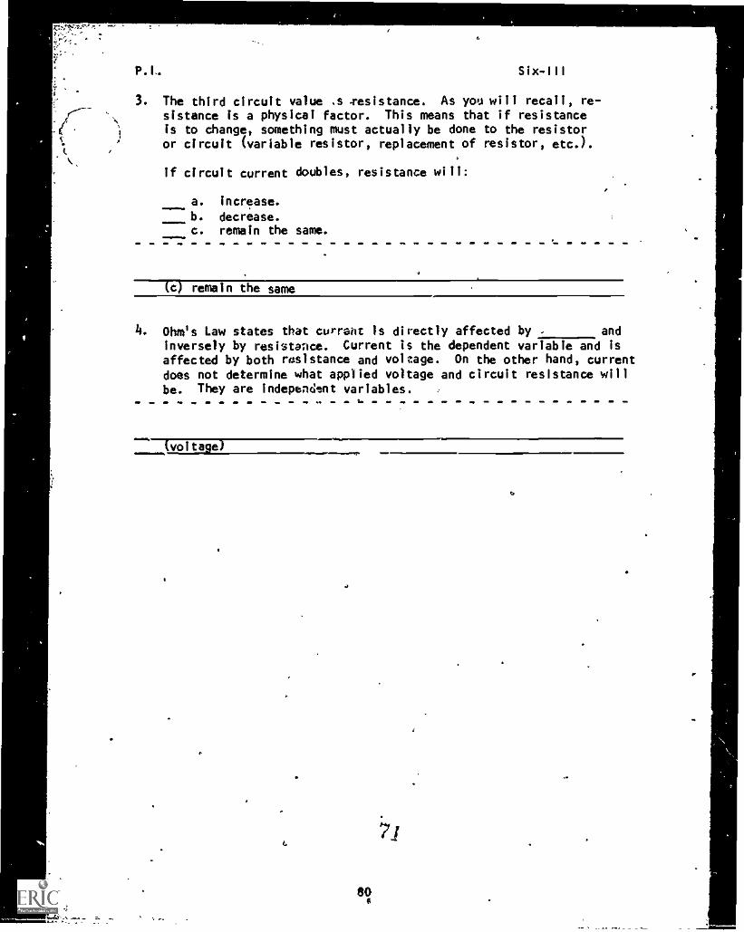
3. The third circuit value .s .resistance. As you will recall, re-sistance is a physical factor. This means that if resistanceis to change, something must actually be done to the resistoror circuit (variable resistor, replacement of resistor, etc.).
If circuit current doubles, resistance will:
a. increase.
b. decrease.c. remain the same.
aMIMMIN.
(c) remain the same
4. Ohm's Law states that currant is directly affected by and
inversely by resistance. Current is the dependent variable and isaffected by both resistance and voltage. On the other hand, currentdoes not determine what applied voltage and circuit resistance willbe. They are indepencient variables.
(voltage)
.71
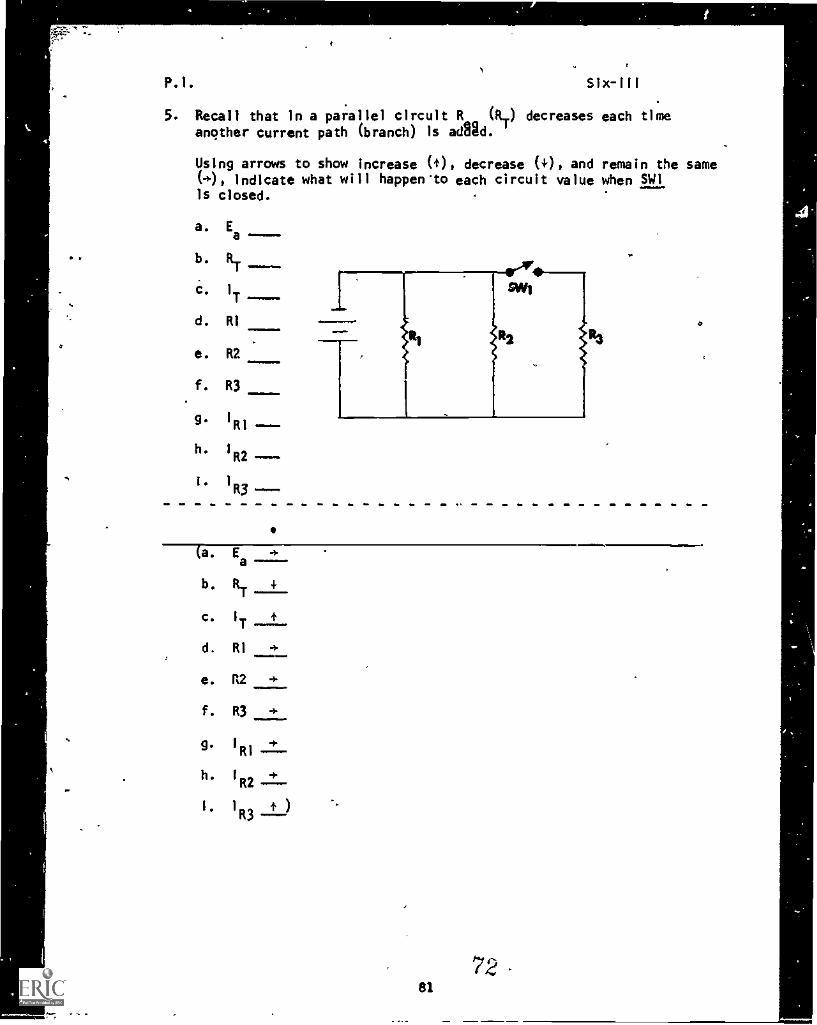
5. Recall that in a parallel circuit R (RT) decreases
another current path (branch) is ad8id.
Using arrows to show increase (4.), decrease (+), and(4.), indicate what will happen"to each circuit valueis closed.
a. Ea-----
RT----
C. I
d. RI
e. R2
f. R3
g.1Rl
h. I
R2
I . 1 a.,
b.
each time
remain the samewhen EL
a. Ea
b. R.
c. I
T
d. RI41111110.1111
e. R2 4-
f. R3 4-
g.1R1 RI ----
h. I 4-R2
I )R3 ----
81
72
1111.1m.
.s
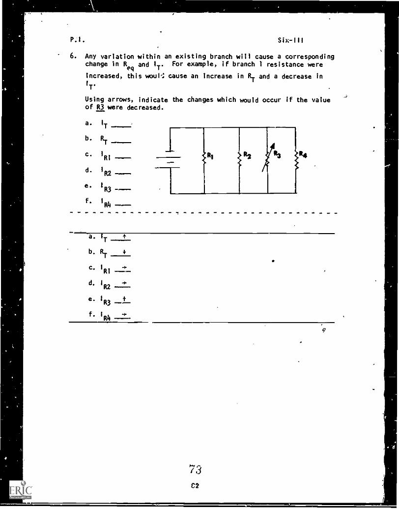
6. Any variation within an existingchange in R
eqand 1
T. For examp
increased, this wou% cause an 1
I
T.
Using arrows, indicate the changof R3 were decreased.
b.
Six-111
branch will cause a correspondingle, if branch I resistance were
ncrease in RT and a decrease in
es which would occur if the value
a. I
Tt---
b. RT
c. I
RI
d. 142
e. I 4-R3 --f. I" ÷
nn
73C2
6
P.I. Six -Ill
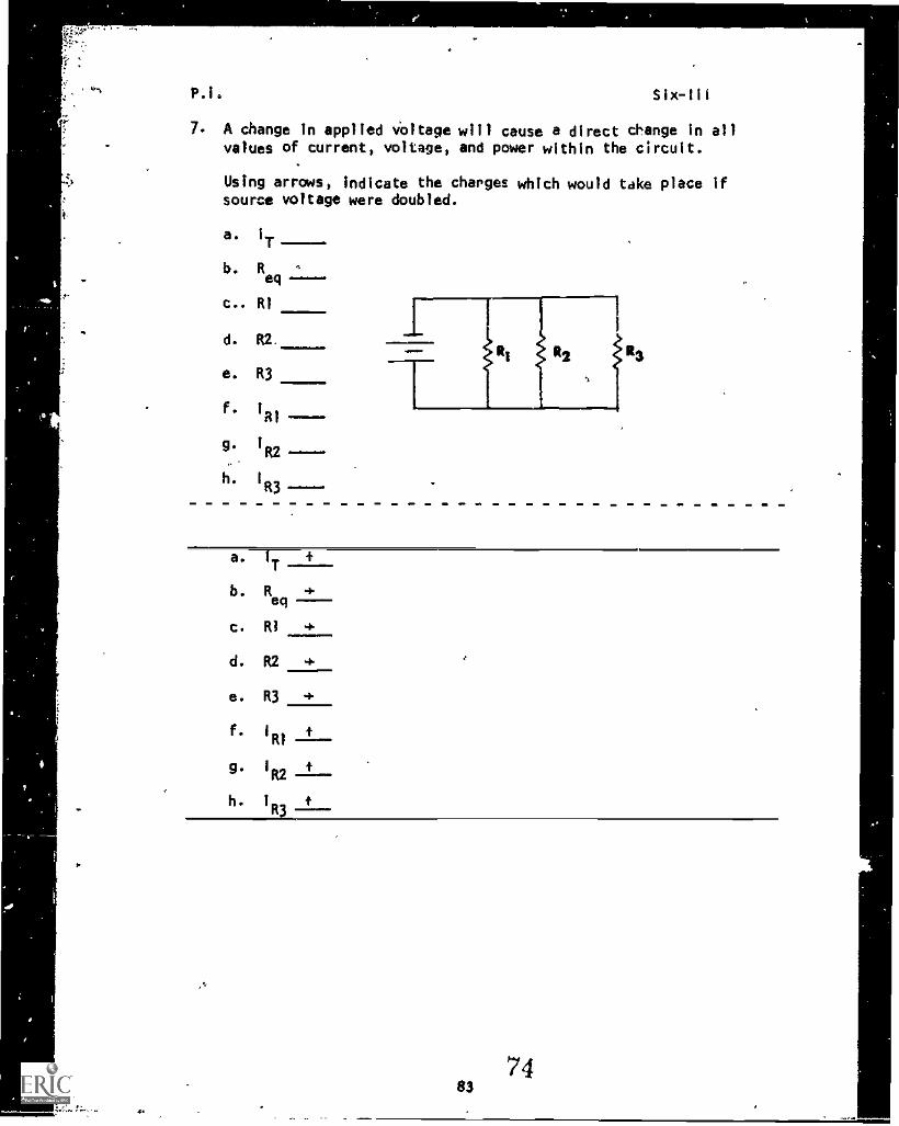
7. A change in applied voltage will cause a direct change in allvalues of current, voltage, and power within the circuit.
Using arrows, indicate the charges which would take place ifsource voltage were doubled.
a. I
T
b. Req
c.. RI
d. R2
e. R3
f.RI
g. 1R2
h. I
R3
a. IT
b. R 4-eq
c. RI +
d. R2 +
e. R3
Six-,111
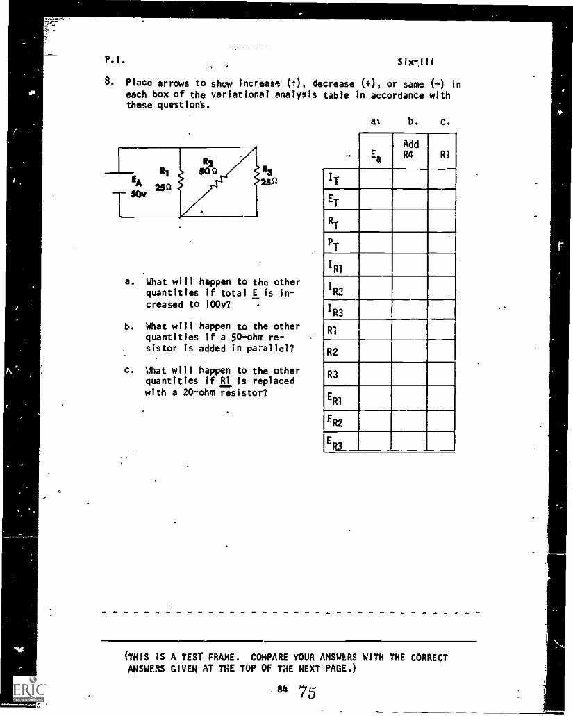
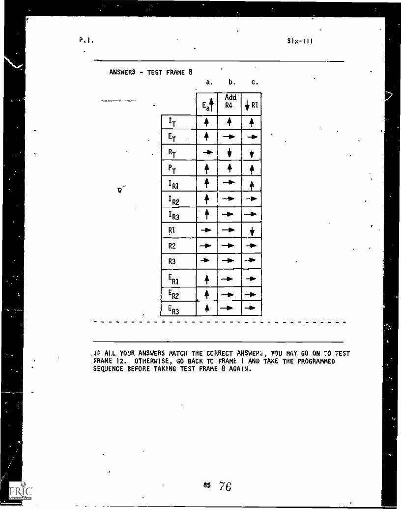
8. Place arrows to show increasg: (0, decrease (+), or same (4) In
each box of the variational analysis table in accordance withthese quest ion's.
a. What will happen to the otherquantities if total E Is in-creased to 1000
b. What will happen to the otherquantities if a 50ohm re-sistor is added in parallel?
c. Mat will happen to the otherquantities If R1 is replaced
with a 20-ohm resistor?
a: b. c.
Ea
AddR4 RI
IT
ET
RT
PT
IR1
IR2
IR3
RI
_
R2
R3
ER1
ER2
1ER3
(THIS IS A TEST FRAME. COMPARE YOUR ANSWERS WITH THE CORRECTANSWERS GIVEN AT TIE TOP OF THE NEXT PAGE.)
.84 75
P.I. Slx-Ill
ANSWERS - TEST FRAME 8
a. b. c.
A
EaT
Add
R4lir RI
IT 4 4 4
ET 4 -la -0.
_RT -a. 4 t
,
PT + 4
IRI+ -a.
1R2
+ -a- -a-
1R3-io.
RI -a. -a- 11,
R2 -a,. -PD. --P.
R3 -la -+. go.
ER1 f -la.
ER2 4 lb. --001-
ER3 4 -la -0.
IF ALL YOUR ANSWERS MATCH THE CORRECT ANSWERS, YOU MAY GO ON 70 TESTFRAME 12. OTHERWISE, GO BACK TO FRAME 1 AND TAKE THE PROGRAMMEDSEQUENCE BEFORE TAKING TEST FRAME 8 AGAIN.
.
85 7 6
P.1. SixIll
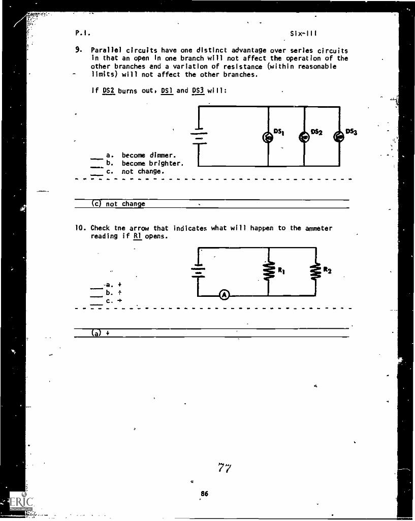
9. Parallel circuits have one distinct advantage over series circuitsin that an open in one branch will not affect the operation of theother branches and a variation of resistance (within reasonablelimits) will not affect the other branches.
If DS2 burns out, DS1 and DS3 will:
a. become dimmer.b. become brighter.c. not change.
(c not change
10. Check tne arrow that indicates what will happen to the ammeterreading if RI opens.
-a.
b. +c.
(a)
77
86
A
P.I.IP
Six-III
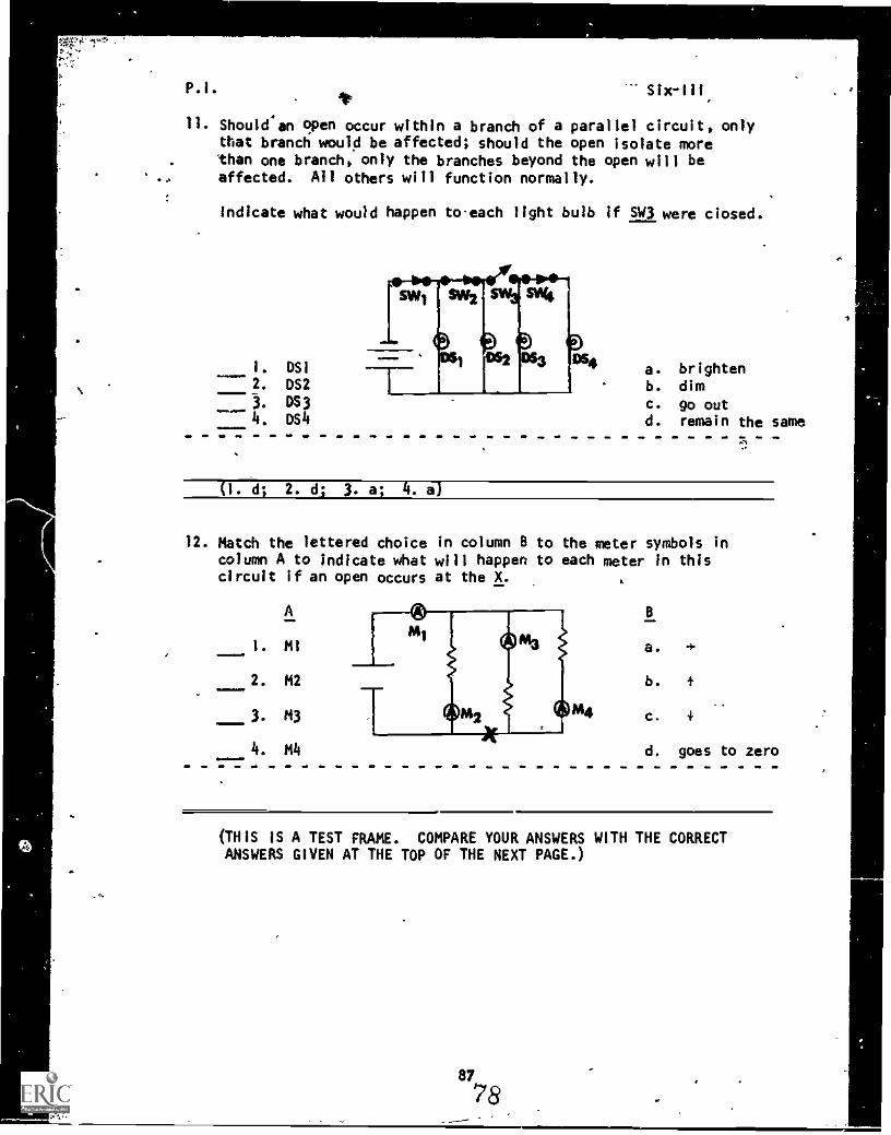
11. Shouldan open occur within a branch of a parallel circuit, onlythat branch would be affected; should the open isolate morethan one branch, only the branches beyond the open will beaffected. All others will function normally.
Indicate what would happen toeach light bulb if SW3 were closed.
1. OS1
2. OS2
4
3.
os4
a. brightenb. dimc. go outd. remain the same
(1. d; 2. dI 3. a; 4. e)
12. Match the lettered choice in column B to the meter symbols incolumn A to indicate what will happen to each meter in thiscircuit if an open occurs at the X.
A
1. mi
2. M2
3. M3
4. m4
B
a. -I-
b. f
c.
d. goes to zero
(THIS IS A TEST FRAME. COMPARE YOUR ANSWERS WITH THE CORRECTANSWERS GIVEN AT THE TOP OF THE NEXT PAGE.)
87
78
Six-111
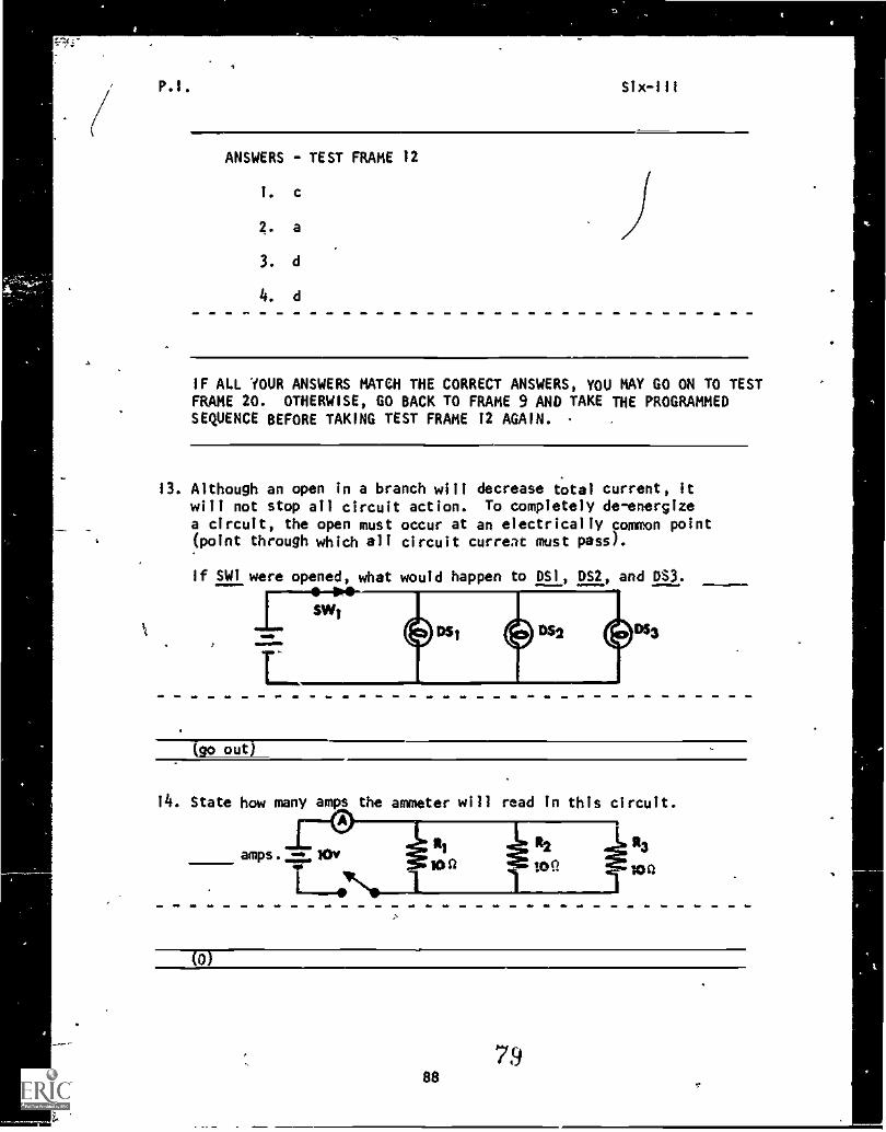
ANSWERS - TEST FRAME 12
1. c
2. a
3. d
4. d
IF ALL YOUR ANSWERS MATCH THE CORRECT ANSWERS, YOU MAY GO ON TO TESTFRAME 20. OTHERWISE, GO BACK TO FRAME 9 AND TAKE THE PROGRAMMEDSEQUENCE BEFORE TAKING TEST FRAME 12 AGAIN.
13. Although an open in a branch will decrease total current, itwill not stop all circuit action. To completely de-energizea circuit, the open must occur at an electrically common point(point through which all circuit curreac must pass).
If SW1 were opened, what would happen to DS1, DS2, and D$3.
MMIONOMM,
L6"1 6"2 DS3
(go out)
14. State how many amps the ammeter will read in this circuit.
R3
10
79SS
P.I. Six-III
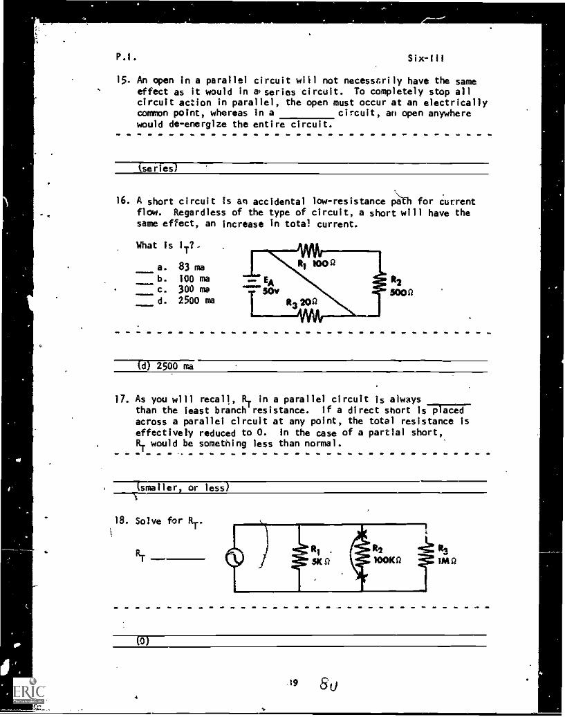
15. An open In a parallel circuit will not necessarily have the sameeffect as it would in &series circuit. To completely stop allcircuit action In parallel, the open must occur at an electricallycommon point, whereas in a circuit, an open anywherewould de-energize the entire circuit.
(serFes)
16. A short circuit is an accidental low-resistance p-t-h for currentflow. Regardless of the type of circuit, a short will have thesame effect, an increase in total current.
What is 1
T
a. 83 mab. 100 mac. 300 mad. 2500 ma
R2
5000
(d) 2500 ma
17. As you will recall, RT in a parallel circuit is alwaysthan the least branch resistance. If a direct short isTj.-1across a parallel circuit at any point, the total resistance iseffectively reduced to 0. in the case of a partial short,RT would be something less than normal.
(smaller or less)
18. Solve for RT.
N1IMtt
(0)
P.1. Six-Ill
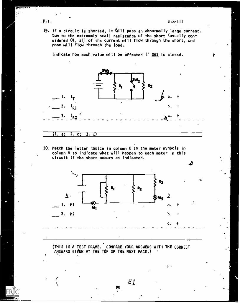
19. If a circuit is shorted, it till pass an abnormally large current.Due to the extremely small resistance of the short (usually con-sidered 0), all of the current will flow through the short, andnone will flow through the load.
Indicate how each value will be affected if SW2 is closed.
2. 11,1".
---- 3* /R2
b. .4.
(1. a; 2. c; 3.
20. Match the letter thoice in column B to the meter symbols incolumn A to indicate what will happen to each meter in thiscircuit if the short occurs as Indicated.
lo
(THIS IS A TEST FRAME. COMPARE YOUR ANSWERS WITH THE CORRECTANSWERS GIVEN AT THE TOP OF THE NEXT PAGE.)
4 .
8190
.
.
P.I. Six-III
=110=1.M
PNSWERS - TEST FRAME 20
I. a
2. c
IF ALL YOUR ANSWERS MATCH THE CORRECT ANSWERS, YOU MAY GO ON TO TESTFRAME 25. OTHERWISE, GO BACK TO FRAME 13 AND TAKE THE PROGRAMMEDSEQUENCE BEFORE TAKING TEST FRAME 20 AGAIN.
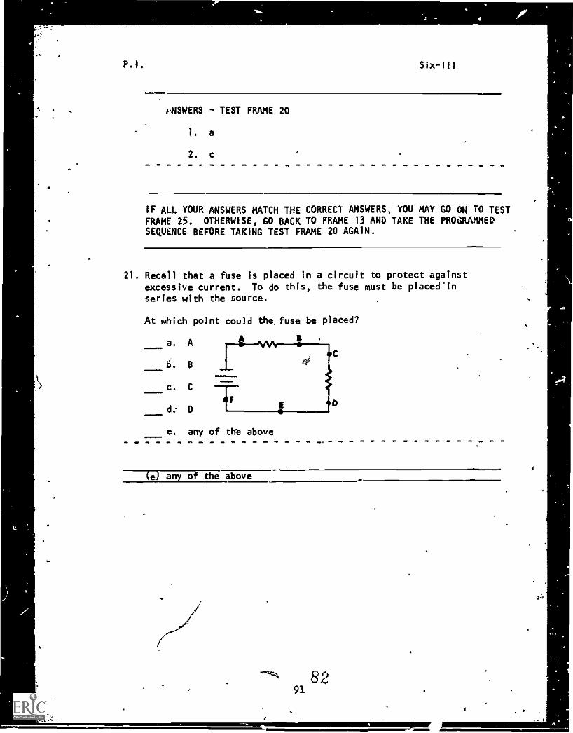
21. Recall that a fuse is placed in a circuit to protect against
excessive current. To do this, the fuse must be placed'inseries with the source.
At which point could the, fuse be placed?
a. A
b'. B
c. C
d.. D
e. any of the above
B
(e) any of the above. .
3
P.I. Six-III
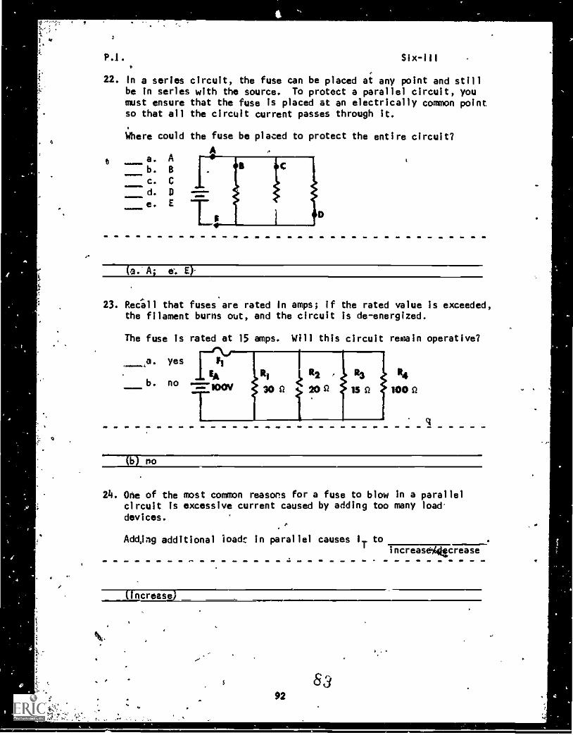
22. In a series circuit, the fuse can be placed at any point and stillbe In series with the source. To protect a parallel circuit, youmust ensure that the fuse is placed at an electrically common pointso that all the circuit current passes through it.
Where could the fuse be placed to protect the entire circuit?
Aa. Ab. B
c. C
d. 0
e. E
(a.. A; e'. E)-
23. RecIll that fuses are rated in amps; If the rated value is exceeded,the filament burns out, and the circuit is de-energized.
The fuse is rated at 15 amps. Will this circuit remain operative?
14
100 SI
no
24. One of the most common reasons for a fuse to blow in a parallelcircuit is excessive current caused by adding too many load.devices.
Adding additional load: in parallel causes IT toincreasaittcrease
Increase
8392
P.I. Six-III
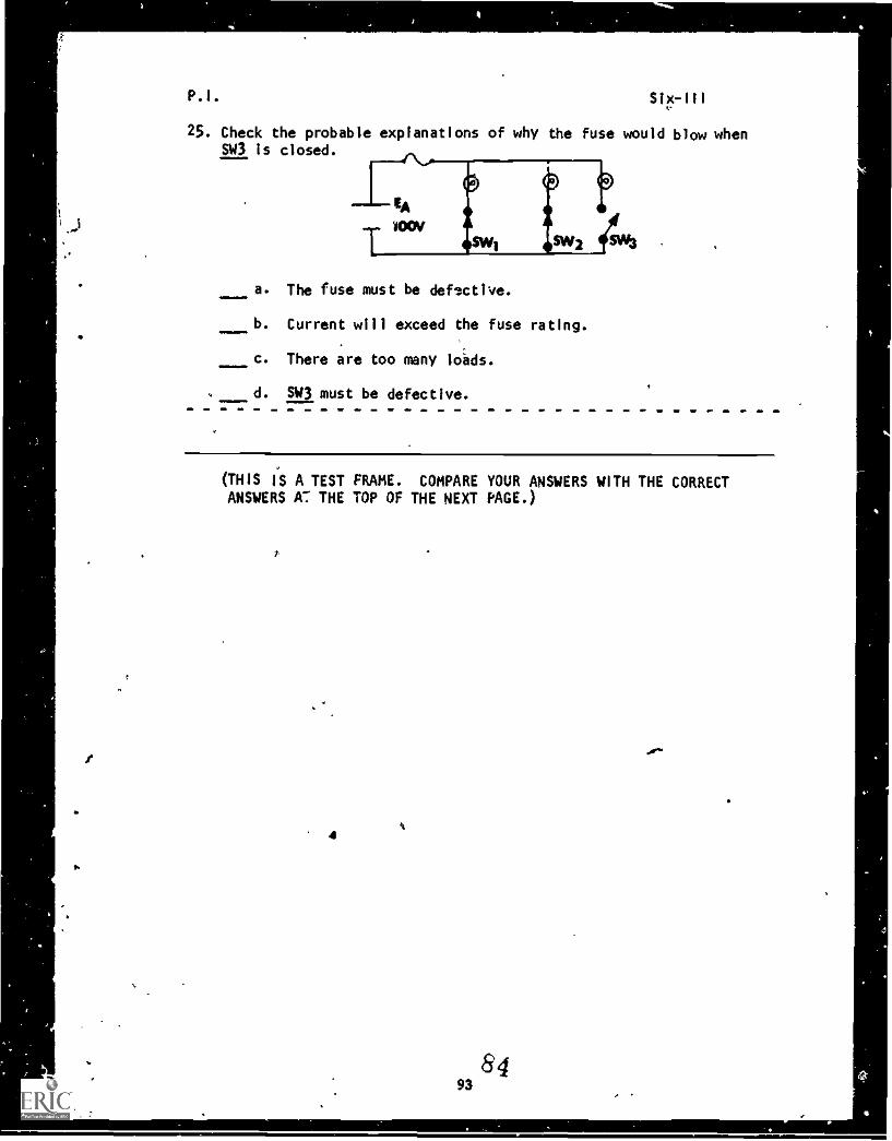
25. Check the probable explanations of why the fuse would blow whenSW3 is closed.
a. The fuse must be defective.
b. Current will exceed the fuse rating.
c. There are too many loads.
aMMEM=d. SW3 must be defective.
(THIS IS A TEST FRAME. COMPARE YOUR ANSWERS WITH THE CORRECTANSWERS V THE TOP OF THE NEXT PAGE.)
I
8493
P.I. Six -III
ANSWERS - TEST FRAME 25
b. Current will exceed the fuse rating.
c. There are too many loads.
IF ANY OF YOUR ANSWERS ARE INCORRECT, GO BACK TO FRAME 21 AND TAKETHE PROGRAMMED SEQUENCE.
IF YOUR ANSWERS ARE CORRECT, YOU MAY TAKE THE PROGRESS CHECK, OR YOU MAYSTUOY ANY OF THE OTHER Ri:SOURCES LISTED. IF YOU TAKE THE PROGRESS CHECKAND ANSWER ALL THE QUESTIONS CORRECTLY, GO ON TO THE NEXT LESSON. IF NOT,
STUDY ANY METHOD OF INSTRUCTION YOU WISH UNTIL YOU CAN ANSWER ALL THEQUESTIONS CORRECTLY.
147
94
Summary
SUMMARYLESSON Ill
Variational Analysis
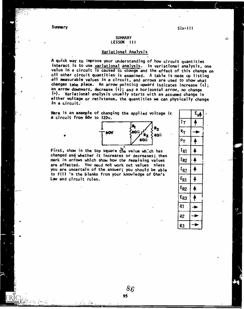
A quick way to improve your understanding of how circuit quantitiesinteract is to use variational analysis. in variational analysis, onevalue in a circuit :s cause change and the effect of this change onall other circuit quantities-is examined. A table is made up listingall measurable values in a circuit, and arrows are used to show whatchanges take place. An arrow pointing upward Indicates increase (t);an arrow downward, decrease (0; and a horizontal arrow, no changeH. Variational analysis usually starts with an assumed change ineither voltage or resistance, the quantities we can physically changein a circuit.
Here is an example of changing the applied voltage isa circuit from 60v to 120v.
12
a
41-
first, show in the top square the value which haschanged an whether it Increases or decreases; thenmark in arrows which show how the remaining valuesare affected. You need not work out values blessyou are uncertain of the answer; you should be ableto fill 'n the blanks from your knowledge of Ohm'sLaw and circuit rules.
SC95
SU 111M r y
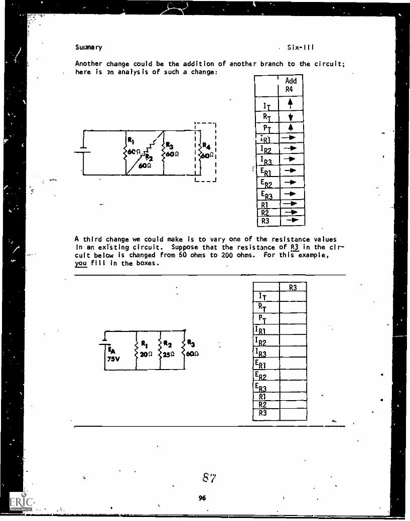
Another change could be the addition of another branch to the circuit;here is an analysis of such a change:
AddR4
I
*
linl -4-
MilRI --41'"
R 0.R3 --40"
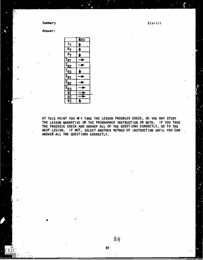
A third change we could make is to vary one of the resistance valuesin an existing circuit. Suppose that the resistance of R3 in the cir-cuit below is changed from 60 ohms to 200 ohms. For this example,r.L.i fill in the boxes.
r
TE:j2209 252 60a3a
V
1
ERI
R2RI
R3
Suninary Six-Ill
Answer:
AR3
IT *RT 4
PT *1111 4'IRL lbw
1R3 *ER1
ER2
ER3
-- ,..
-RI- =It__R2 --41°R3 4
AT THIS POINT YOU MiY TAKE THE LESSON PROGRESS CHECK, OR YOU MAY STUDYTHE LESSON NARRATIVE OR THE PROGRAMMED INSTRUCTION OR BOTH. IF YOU TAKETHE PROGWESS CHECK AND ANSWER ALL OF THE QUESTIONS CORRECTLY, GO TO THENEXT LESOH. IF NOT, SELECT ANOTHER METHOD OF INSTRUCTION UNTIL YOU CANANSWER ALL THE QUESTIONS CORRECTLY.
97
68
A
44.
, ,
'V
11,
t-,
tiWe
BASIC ELECTRICITY.AND ELECTRONICS
INDIVIDUALIZED LEARNING SYSTEM
MODULE SIXLESSON IV
Troubleshooting Parallel Circuits
Study Booklet
9099
4,0
O
Overview Six-IV
OVERVIEW'
LESSON IV
Troubleshooting Parallel Circuits
In this lesson, you will study and-learn about the following:
-shorts
-opens
- -practical experiments in troubleshooting
Each of the above topics will be discussed in the order listed. As
you proceed through ttiis lesson, observe and follow directions care-
fully.
BEFORE YOU START THIS LESSON, PREVIEW THE LIST O. STUDY RESOURCES
ON THE NEXT PAGE.
4.
Study Resources Six-IV
LIST OF STUDY RESOURCES
LESSON IV
Troubleshooting Parallel Circuits
To learn the caterial in this lesson, you haye the option of choosing,
according to your experience and preferences, any or all of the following:
STUDY BOOKLET;
Lesson harrative
Lesson Summary
ENRICHMENT MATFP:AL:
NAVPERS 9900i-la "Basic Electricity, Direct Current."
Fundamentals of Electronics. Bureau of Naval Personne1.
Washlagton, D.C.: U.S. Government Printing Office, 1965.
YOU MAY NOW STUDY ANY OR ALL OF THE RESOURCES LISTED ABCVE. YOU MAY
TAKE THE PRDGRESS CHECK AT ANY TIME.
I
tok9 2
Narrative
NARRATIVELESSON IV
Troubleshooting Parallel Circuits
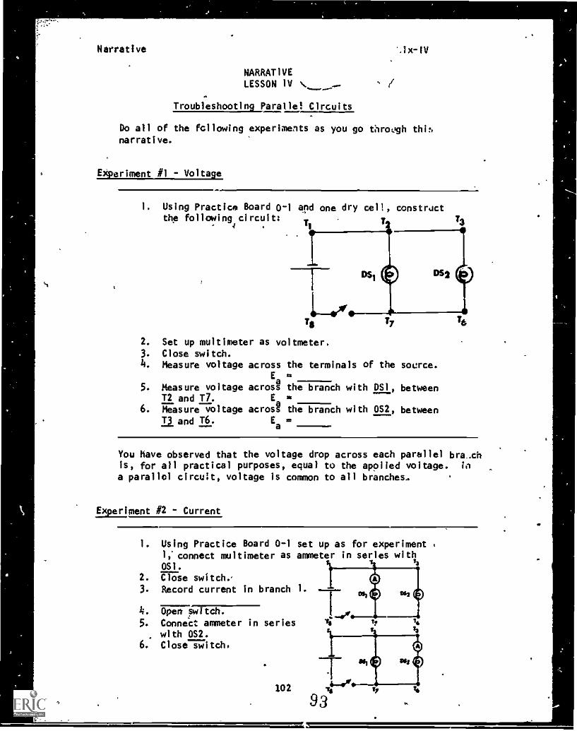
Do all of the following experiments as you go through thi,,narrative.
Experiment #1 - Voltage
i. Using Practice Board 0-1 and one dry cell, constrdctthe following circuit:
T24
Ts
2. Set up multimeter as voltmeter.3. Close witch.4. Measure voltage across the terminals
5.Ea "
Measure voltage across the branch wiT2 and!".
Ea6. Measure voltage across the branch wi
T3 and T6. Ea=
of the source.
th DSI, between
th za, between
You have observed that the voltage drop across each parallel bra-chis, for all practical purposes, equal to the applied voltage. in
a parallel circuit, voltage is common to all branches..
Experiment #2 - Current
1. Using Practice Board 0-1 set up as for experimentI,' connect multimeter as ammeter in series withOS1.
2. ?Tale switch..
3. Record current in branch 1.
4. Open sw tch.
5. Connect ammeter in serieswith Dn.
6. Close switch.
Z,
102
Narrative
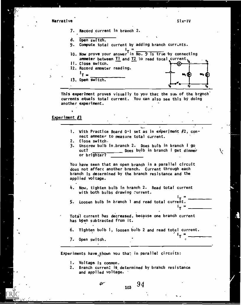
7. Record current in branch 2.
d. Open switch.9. Compute total current by adding branch currents.
I
.
10. Now prove your answer' tn No. 9 is trueby connectingammeter between 11 and T2 to read total current
11. Close switch.12. Record ammeter reading.
1T
13. Open 7,571155T7--------
Six-IV
This experiment proves visually to you that the sues of the branch'currents equals total current. You can also see this by doinganother experiment.
Experiment aI. With Practice Board 0 -i set as in experiment #2, con-
nect ammeter to measure total current.2. Close switch.3. Unscrew bulb in.branch 2. Does bulb In branch 1 go
out? Does bulb in branch I get dime X.
or briiRer?
You have seen that an open branch in a parallel circuitdoes not affect another branch. Current through eachbranch is determined by the branch resistance and theapplied voltage.
4. Now, tighten bulb in branch 2. Read total currentwith both bulbs drawing zurrent.
I
Ttt
5. Loosen bulb in branch 1 and read total current.I
T
Tota1 current has decreased, because one branch currenthas bpen subtracted from it.
6. Tighten bulb 1, loosen bulb 2 and read total current.
7. Open switch.T
aril/11mM
Experiments have shown YOU that in parallel circuits:
1. Voltage is common.2. Branch current is- determined by brahch resistance
and applied voltage.
9 4103
lb
Narrative -Six-1V
3. Total current is equal to the sum of the individualbranch currents:
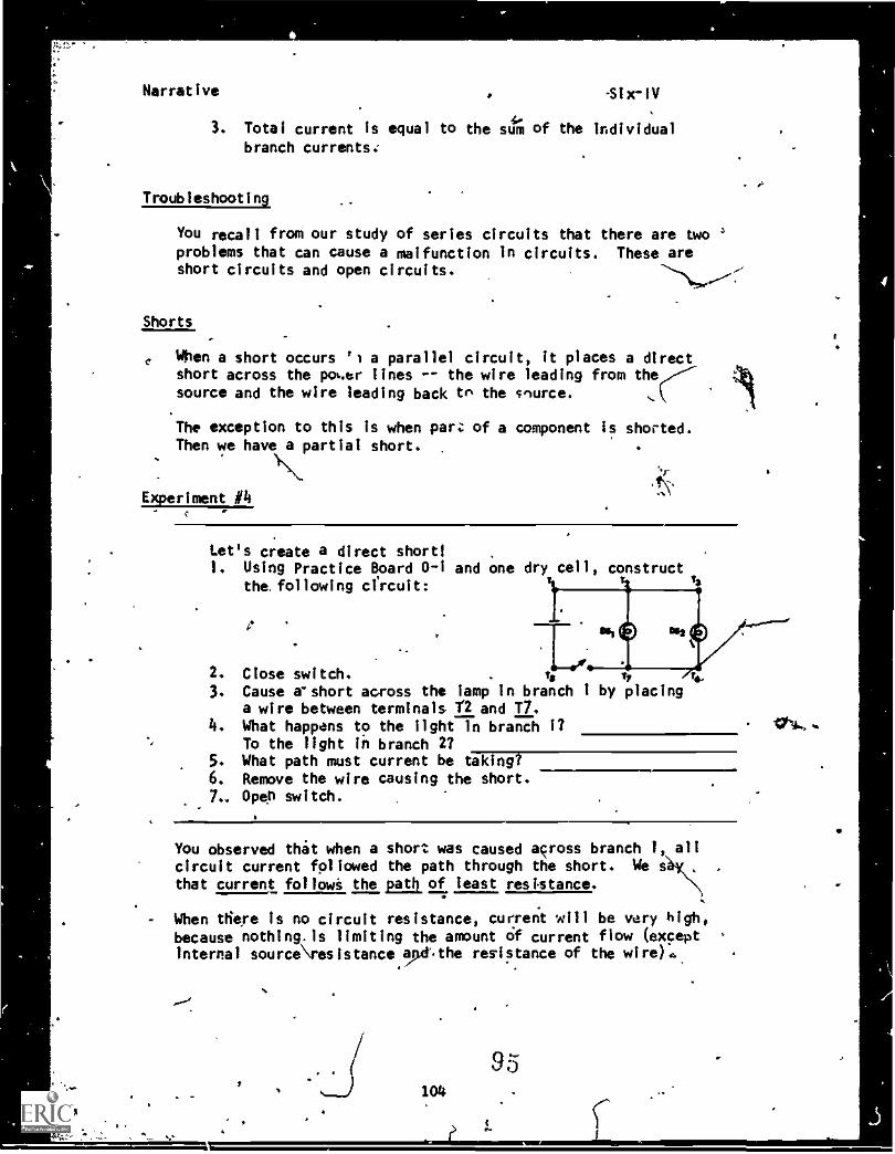
Troubleshooting
You recall from our study of series circuits that there are two 'problems that can cause a malfunction in circuits. These areshort circuits and open circuits.
Shorts
, When a short occurs '1 a parallel circuit, it places a directshort across the pol..er lines -- the wire leading from thesource and the wire leading back tr. the c'urce.
The exception to this is when pares of a component Is shorted.Then we have a partial short.
Experiment 14
Let's create a direct short!1. Using Practice Board 0-1 and one dry cell, construct
the. following circuit:ta
2. Close switch. . Ts Tr ip3. Cause ashort across the camp in branch I by placing
a wire between terminals Y2 and T7.4. What happans to the light In branch 1? tai.,.
To the light in branch 2?5. What path must current be taking?6. Remove the wire causing the short.7.. Open switch.
.
You observed that when a short was caused across branch 1, allcircuit current followed the path through the short. We sthat current followi the path of feast resistance.
- When there is no circuit resistance, current will be vary high,because nothing.is limiting the amount of current flow (exceptinternal source\resistance ,the resistance of the wirer.,
cOs. 104
95
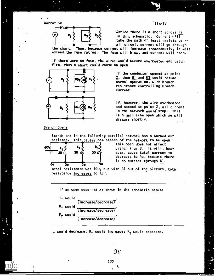
.1
I
Narrative Six-IV
i,iotice there is a short across
in this schematic. Current 011take the path of least resista..ce --all circuit current will go through
the short. Then, because current will increase tremendously, it W11exceed the fuse rating. The fuse will blow, and current will stop.
If there were no fuse, the wires would become overheatec. and catchfire, thus a short could cause an open.
Branch Opens
Branch one inresistor. Thi
If the conductor opened at pointX, then RI and R3 could resumenormal operation, with branchresistance controlling branchcurrent.
If, however, the wire overheatedand opened at point 2, all currentin the network would stop. Thisis a main-line open which we w:11discuss shortly.
the following parallel network has a burned outs causes one branch of the network to be open.'
This open does not affectbranch 2 or 3. It will, how-ever, cause total current to
. decrease to 4a, because thereis no current through 51.
2o6a
Total resistance was 10, but with RI out of the picture, total
resistance increases to 15Q.
If an open occurred as shown in the schematic abo,e:
I
Twould
(-increase /decrease)'
RT
would
(increase/decrease)PT
would
(increase/decrease)
~1111=. 1110IT would decrease; RT would increase; PT would decrease.
96'Os
. %
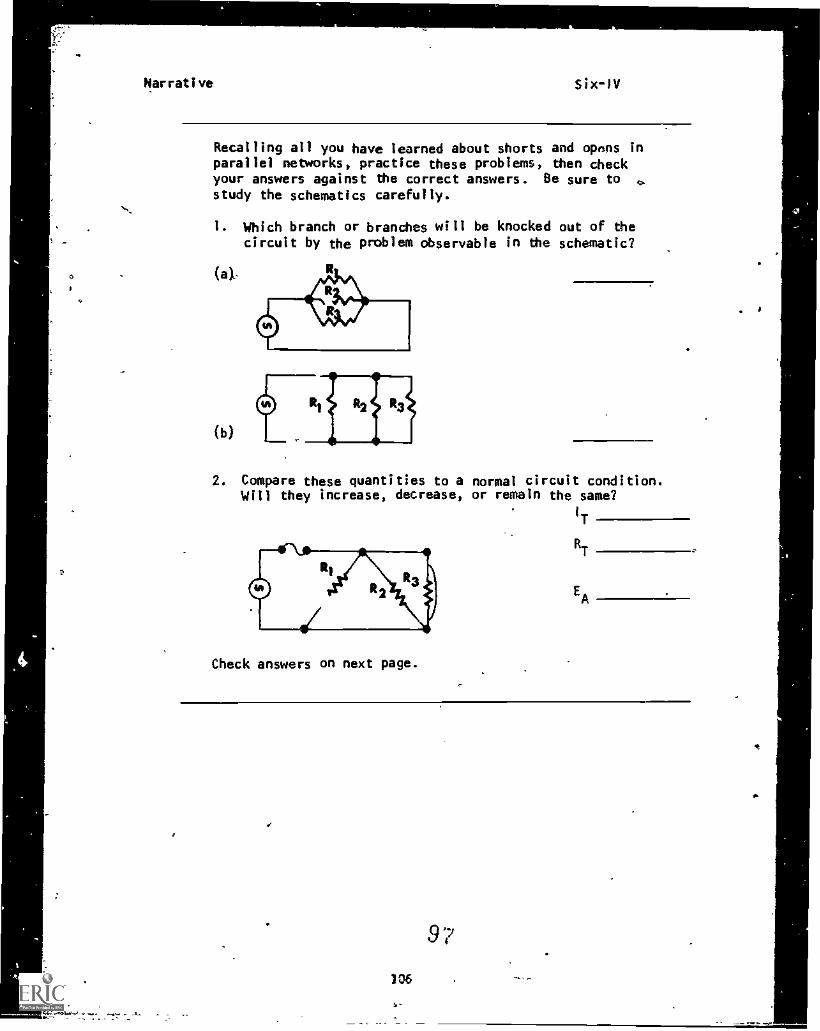
Narrative Six-1V
Recalling all you have learned about shorts and opons inparallel networks, practice these problems, then checkyour answers against the correct answers. Be sure to ,study the schematics carefully.
1. Which branch or branches will be knocked out of thecircuit by the problem observable in the schematic?
(b)
2. Compare these quantities to a normal circuit condition.Will they increase, decrease, or remain the same?
1
T
RT
EA
Check answers on next page.
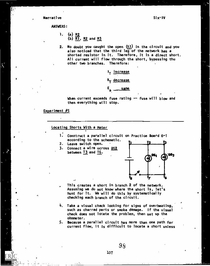
Narrative Six-IV
ANSWERS:
1. (a) R2
(b) R1, R2 and R3
2. No doubt you caught the open (R1) In the circuit and youalso noticed that the third leg of the network has ashorted resistor in it. Therefore, it is a direct short.All current will flow through the short, bypassing theother two branches. Therefore:
IT increase
RT decrease
sameEa
When current exceeds fuse rating -- fuse will blow andthen everything will stop.
Experiment #5
Locating Shorts With a Meter
1. Construct a parallel circuit on Practice Board 0-1according to the schematic.
2. Leave switch open.3. Connect a wire across DS2
between T3 and T6.
4*6
This creates a short in branch 2 of the network.Assuming we do not know where the short is, let'shunt for It. We will do this by systematicallychecking each branch of the circuit.
4. Take a visual check looking for signs of overheating,such as charred parts or smoke damage. If the visualcheck does not lor:ate the problem, then set up the
ohmmeter.
5. Because a parallel circuit has more than one path forcurrent flow, it is difficult to locate a short unless
Narrative
we check each branch systematically. Operating a cir-cuit with a short in it may cause considerable damageto good components, so most troubleshooting should bedone with an ohmmeter. Let's begin by making sure thecircuit has no voltage across the branches, then connect-ing the ohmmeter across the loads. For this circuit,clip the test leads to points T2 and Ti.
What is the ohmmeter reading?
(Ott)
6.- Place probes across 72 and Ti. You measure 0 butyou know that there should be some resistance in t.t.bulb.
7. Disconnect the wire from DS1 to T2.8. Measure across T2 and T7 again. You still get a 0
reading inelcating the circuit still is shorted; there-fore, the trouble does not occur in this branch.
9. Reconnect DS1, disconnect DS2 and the wire shorting it.10. Measure across DS1. The meter reads some resistance,
indicating that the short has been isolated. You havelocated the short as being in branch 2.
11. Now the problem can be corrected and the circuit re-stored to normal.
AT THIS POINT, YOU MAY TAKE THE PROGRESS CHECK, OR YOU MAY STUDY ANYOF THE OTHER RESOURCES LISTED. IF YOU TAKE THE PROGRESS CHECK ANDANSWER ALL OF THE QUESTIONS CORRECTLY, YOU HAVE MASTERED THE MATERIALAND ARE READY TO TAKE THE MODULE TEST.. SEE YOUR CLASSROOM SUPERVISOR.
IF YOU DECIDE NOT TO TAKE THE PROGRESS CHECK AT THIS TIME, OR IF YOUMISSED ONE OR MORE QUESTIONS, STUDY ANY METHOD OF INSTRUCTION YOU WISHUNTIL YOU HAVE ANSWERED ALL THE PROGRESS CHECK QUESTIONS CORRECTLY.THEN SEE YOUR CLASSROOM SUPERVISOR AND ASK TO TAKE THE MODULE TEST.
99108
kt
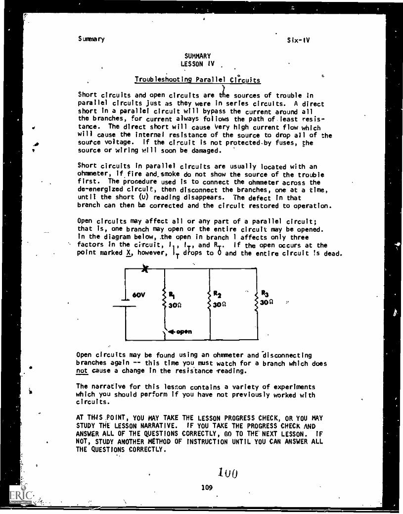
Summary Six -IV
SUMMARYLESSON IV
Troubleshooting Parallel Circuits
Short circuits and open circuits are tie sources of trouble Inparallel circuits just as they were in series circuits. A directshort in a parallel circuit will bypass the current around allthe branches, for current always follows the path of least resis-tance. The direct short will cause Very high current flow whichwill cause the internal resistance of the source to drop all of the
A. source voltage. If the circuit is not protectedby fuses, thesource or wiring will soon be damaged.
Short circuits in parallel circuits are usually located with anohmmeter, if fire and smoke do not show the source of the troublefirst. The procedure used is to connect the ohmmeter across thede energized circuit, then disconnect the branches, one at a timeuntil the short 0) reading disappears. The defect in thatbranch can then be corrected and the circuit restored to operation.
Open circuits may affect all or any part of a parallel circuit;that is, one branch may open or the entire circuit may be opened.In the diagram below, .the open in branch 1 affects only threefactors in the circuit, IT, and RT. If the open occurs at thepoint marked X, however, iT drops to 0 and the entire circuit ts dead.
R2
30s1
R3
30a
Open circuits may be found using an ohmmeter and *disconnectingbranches again -- this time you must watch for a branch which doesnot cause a change in the resistance leading.
The narrative for this lesson contains a variety of experimentswhich you should perform if you have not previously worked withcircuits.
AT TH.'S POINT, YOU MAY TAKE THE LESSON PROGRESS CHECK, OR YOU MAYSTUDY THE LESSON NARRATIVE. IF YOU TAKE THE PROGRESS CHECK ANDANSWER ALL OF THE QUESTIONS CORRECTLY, GO TO THE NEXT LESSON. IF
NOT, STUDY ANOTHER METHOD OF INSTRUCTION UNTIL YOU CAN ANSWER ALLTHE QUESTIONS CORRECTLY.