DOCKETED - Californiadocketpublic.energy.ca.gov/PublicDocuments/16-OII-01/TN214218... ·...
150
DOCKETED Docket Number: 16 - OII - 01 Project Title: Order Instituting Informational Proceeding for Drought Executive Order B - 37 - 16 TN #: 214218 Document Title: LADWP Comments: Recommend LADWP's Water Loss Studies As Resources for the State's Water Loss Efforts Description: N/A Filer: System Organization: LADWP Submitter Role: Public Agency Submission Date: 10/27/2016 4:50:02 PM Docketed Date: 10/27/2016
Transcript of DOCKETED - Californiadocketpublic.energy.ca.gov/PublicDocuments/16-OII-01/TN214218... ·...
DOCKETED
Docket Number:
16-OII-01
Project Title: Order Instituting Informational Proceeding for Drought Executive Order B-37-16
TN #: 214218
Document Title:
LADWP Comments: Recommend LADWP's Water Loss Studies As Resources for the State's Water Loss Efforts
Description: N/A
Filer: System
Organization: LADWP
Submitter Role: Public Agency
Submission Date:
10/27/2016 4:50:02 PM
Docketed Date: 10/27/2016

Comment Received From: Jevon LamSubmitted On: 10/27/2016Docket Number: 16-OII-01
Recommend LADWP's Water Loss Studies As Resources for the State's Water Loss Efforts
LADWP is submitting the following comment letter, which includes as attachments the Executive Summary for our Water Loss Audit and Component Analysis Study and our Water Loss Task Force Action Plan.
LADWP has done extensive work to research, evaluate, and implement water loss control strategies for its own distribution system. We believe our experiences and knowledge gained from these efforts would be very helpful to the State agencies. We would like to offer these studies and our assistance to the CEC, SWRCB, and DWR as resources to assist your work on water loss efforts to address Drought Executive Order B-37-16.
Additional submitted attachment is included below.
••411 Los Angeles ln~I Department of Water & Power
ERIC GARCETTI Mayor
October 27, 2016
Mr. Sean Steffensen
Commission l\ I EL LEV IN E, President WILLIAl\I \V. FUNDERBURK JR., \lice President JI LL BANKS BARAD l\IICH/\EL F. FLE1\ll NG CHRISTI /\ E. NOON/\ B/\RB/\Ri\ E. l\ IOSCHOS, Secretary
California Energy Commission Appliances and Existing Buildings Office 1516 Ninth Street, MS-25 Sacramento, California 95814-5512
Dear Mr. Steffensen:
Subject: Innovative Water Loss Detection and Control Technologies
DAV ID H. WRIGHT General Manager
The Los Angeles Department of Water and Power (LADWP) appreciates the opportunity to comment in response to the Governor's Executive Order B-37-16 (Executive Order) , which directs the California Energy Commission (CEC) to "certify innovative water conservation and water loss detection and control technologies that also increase energy efficiency." Furthermore, it is recognized that the CEC's efforts will assist the State Water Resources Control Board (SWRCB) and the Department of Water Resources (DWR) in directing actions to minimize water system leaks.
LADWP agrees that reducing water loss is an important component to improving water efficiency throughout California. We have performed extensive studies and actions on water loss control and would like to offer our assistance to the CEC, SWRCB, and DWR. The following studies summarize the water loss control work we have completed, which will be valuable resources to the State agencies. These documents can be downloaded at http://www. ladwp.com/waterconservation .
I. Water Loss Audit and Component Analysis Study {Attachment 1)
In September 2013, LADWP completed a comprehensive Water Loss Audit and Component Analysis Study (Study) . For the Study, LADWP hired a water loss technical expert, Water Systems Optimization Inc. , to perform a comprehensive water loss
Putting Our Customers First~ I I I N. Hope Street, Los Angeles, Califo rnia 90012-2607 Afa i/i11g Address: Box SI 111, Los Angeles, CA 90051-5700
Telephone (2 13) 367-421 I www.LADWP.com

Mr. Sean Steffensen Page 2 October 27, 2016
analysis. This work included: • Validating LADWP's water loss audit data • Completing a component analysis of real losses • Performing·leak detection • Analyzing district metered areas in three system pressure zones
The Study confirmed that LADWP has very low levels of water loss and identified potential strategies to further reduce water loss and improve data quality.
II. Water Loss Task Force Action Plan (Attachment 2)
LADWP formed its Water Loss Task Force (Task Force) of over 100 staff to capture the many specialties needed to implement water loss control strategies for our complex · distribution system. The Task Force evaluated all of the potential strategies from the Study and is pursuing all actions that are feasible and cost effective to execute. These actions include:
• Enhancing production meter calibration and maintenance procedures • Streamlining operations and leak repair databases • Testing a representative sample of customer meters • Increasing pressure monitoring and conducting pressure management studies • Creating a regular acoustic leak detection program • Installing advanced metering infrastructure on fire service meters to prevent theft
These actions are detailed in LADWP's Water Loss Task Force Action Plan (Action Plan) and are currently being implemented by the Task Force.
Ill. Infrastructure Improvements and New Technology Evaluation
In addition to the Task Force efforts, LADWP has been proactively increasing its pipeline replacement. Since 2007, LADWP has replaced over one million feet of pipe. With funding assistance from our new water rates passed in April 2016, LADWP further ramped up its infrastructure renewal and rehabilitation efforts. LADWP is dedicating over $850 million to pipe replacement in the next three years.
LADWP is also very active in engaging with private companies in the evaluation of new technologies to reduce water losses. We have several ongoing and completed pilot studies that are evaluating the following technologies:
• Leak detection acoustic sensors • Hydraulic and leak modeling and data management

Mr. Sean Steffensen Page 3 October 27, 2016
• Pipe assessment and rehabilitation • Broadband electromagnetic technology • Pressure transient detection and reporting • Pressure and flow monitoring
IV. Important Considerations For Developing Water Loss Requirements
LADWP encourages State agencies to use our studies as a resource to assist with its work to fulfill water loss requirements of the Executive Order. Through extensive water loss control efforts, LADWP has gained a greater understanding of strategies that are effective. The following two important water loss considerations have been identified for State agencies to take into account:
1. Effective Water Loss Strategies Vary Greatly By Each Supplier
CE C's certification process for water loss detection and control technologies is a valuable tool to provide water suppliers information on potential strategies to consider. However, through our experience developing our Action Plan, LADWP has found that a supplier-specific assessment is necessary to determine the strategies that will work. Water and energy savings as well as feasibility of implementation for each water loss strategy will be highly dependent on each water supplier's characteristics, which include:
• Real loss components (background, reported, and unreported leakage) • Minimum operating pressures and system elevations • Pipe conditions • Layout constraints of system infrastructure
LADWP recommends the State agencies consider these constraints in the development of its certified water loss detection and control technologies process. Water suppliers can use this list as an information clearinghouse of available water loss control technologies, but must ultimately perform an individualized analysis to determine which strategies work best for their water system.
2. Consider Resource Requirements of Water Loss Control Strategies
As many water loss strategies can be highly resource intensive, LADWP recommends that State agencies take into account cost-effectiveness when developing strategies to fulfill the Executive Order's water loss requirements. LADWP is expecting to spend $4.4 million in capital costs and two million dollars

Mr. Sean Steffensen Page4 October 27, 2016
in ongoing operations and maintenance costs to implement our Action Plan. These costs only include the cost of the first phase of a multi-phased effort for many of the actions identified in the Action Plan, which could total up to one billion dollars upon full-scale implementation. This is in addition to the $850 million dedicated for pipe replacement in the next three years.
Furthermore, it will take several years to fully implement all of the strategies outlined in the Action Plan. Therefore, the framework should allow water suppliers adequate time to implement all of the water loss strategies that may be required to meet the provisions of Senate Bill 555 and the Executive Order.
LADWP is grateful to be included in the draft framework process to fulfill the Executive Order requirements. Should you have any questions or would like our technical assistance for the State agencies' water loss work, please contact Ms. Sofia Marcus, Project Manager for the Water Loss Task Force, at (213) 367-0925 or by e-mail at sofia [email protected].
Sincerely,
~?~ Nancy H. Sutley ) Chief Sustainability and Economic Development Officer
SM:yrg By e-mail Attachments c: Mr. Andrew McAllister, Commissioner, California Energy Commission
Ms. Felicia Marcus, Chair, State Water Resources Control Board Mr. Max Gomberg, State Water Resources Control Board
Mr. Mark Cowan, Director, California Department of Water Resources Mr. Todd Thompson, California Department of Water Resources
Ms. Sofia Marcus
Los Angeles Department of Water and Power: WATER LOSS AUDIT & COMPONENT ANALYSIS
PROJECT Fiscal Year 2010-2011
EXECUTIVE SUMMARY
SEPTEMBER 2013
Water Resources
smarcu
Typewritten Text
Attachment 1
smarcu
Typewritten Text
smarcu
Typewritten Text
smarcu
Typewritten Text
smarcu
Typewritten Text
smarcu
Typewritten Text
smarcu
Typewritten Text


i
EXECUTIVE SUMMARY The goal of the Water Loss Audit and Component Analysis Project (Project) was to fulfill the requirements of Best Management Practice (BMP) 1.2 in the California Urban Water Conservation Council (CUWCC) Memorandum of Understanding (MOU) that were due on June 30, 2013. The BMP requires an annual audit of the water system, and the completion of a component analysis every 4 years. With the passage of Assembly Bill 1420 in 2009, compliance with the CUWCC BMPs is mandatory for a water agency to qualify for state grants and loans. For the Project, Water Systems Optimization (WSO) examined the efficiency of the Los Angeles Department of Water and Power (LADWP) water distribution system. Specifically, WSO investigated the current ability to accurately identify real and apparent losses, determined the economic optimum level of water losses, and identified, prioritized, and recommended the most efficient and cost-effective loss intervention strategies to minimize water loss. The audit period examined was from July 1, 2010 to June 30, 2011 (FY 2010-2011). A Water Conservation Field Services Program Grant was received from the United States Bureau of Reclamation to partially fund contract costs for the Project. This report includes the results of the required BMP water audit, the component analysis of real and apparent losses, the economic level of leakage (ELL) analysis, and the results of the pilot leak detection and District Metered Area (DMA) efforts. The Project results indicate an efficient water system, per national standards, with low levels of water losses. However, the research located several components in the water system that will improve the system’s efficiency while saving costs.
ES.1 Overview of Project ES.1.1 AWWA Water Balance The American Water Works Association (AWWA) Water Balance uses methodology developed by the International Water Association (IWA) to account for all water entering and leaving the distribution system. The water audit utilizes the IWA/AWWA standardized Water Balance methodology to disaggregate and validate components of System Input Volume, Consumption Volume, Apparent Loss Volume, and Real Loss Volume in an effort to identify potential for reduction of Water Loss Volumes. The basic components of the Water Balance for LADWP are as follows:
System Input Volume (SIV) includes water produced at all water treatment plants, water pumped from wells, and bulk water imports. Three main sources supply LADWP’s potable water distribution network: the Los Angeles Aqueduct (LAA), purchased water from the Metropolitan Water District of Southern California (MWD), and groundwater from LADWP’s well fields. The metering accuracy for each of these supplies was carefully examined for the

ii
FY 2010-2011 water loss audit. When dealing with such high volumes, meter accuracy can have a significant impact on the water balance results. The methodology used to determine the final System Input Volume is discussed in detail in Section 1.
Authorized Consumption includes metered and un-metered water taken by customers and other uses that are authorized by LADWP. The main component of Authorized Consumption is Billed Metered Authorized Consumption (BMAC). The billing database was examined, checking the data integrity of the billing records on the whole and analyzing consumption by meter size and customer type to isolate instances of potential meter under-registration or over-registration. Other components of Authorized Consumption include water from system flushing and fire fighting. The components of Authorized Consumption are calculated and explained in Section 2.
Water Losses are calculated by subtracting Authorized Consumption from System Input Volume. Water Losses are divided into two main categories: Apparent Losses and Real Losses. This calculation is detailed in Section 3 and is shown in Table ES-1.
Table ES-1: Water Losses Calculation
VALUE FY 2010-2011 VOLUME
(MG) (AF)
System Input Volume (A) – see Section 1 175,575.83 538,822.44
Authorized Consumption (B) – see Section 2 166,662.61 511,468.77
Water Losses ( (A) - (B) ) 8,913.22 27,353.67
Apparent Losses are non-physical losses that occur due to customer meter inaccuracies, data handling errors, and water theft. The term “apparent” is applied because water is consumed but is not properly measured. For small meters (2” or smaller), a representative sample of meter test results were analyzed to determine the meter accuracy for the whole small meter population (see Section 4.2.1). Based on these test results, WSO also completed an economic analysis of meter replacement scenarios (see Section 10.1). For large meters (3” or larger), WSO examined the current meter maintenance schedule and analyzed an alternative routine that would keep under-registration at an economically efficient level (see Section 10.2).
Real Losses are physical water losses such as leaks, breaks and overflows. It is the remaining volume after Authorized Consumption and Apparent Losses are subtracted from System Input Volume. Real Losses are characterized as Reported Leaks, Unreported Leaks, and Background Leaks. Discussion on how Real Losses are calculated through the water balance is presented in Section 5. Additionally, District Metered Areas (DMAs) in three distribution system service zones were set up as a pilot project to estimate the amount of Water Losses and Unreported Leaks that occur on a smaller scale (see Section 9). An analysis of economically efficient Real Loss reduction strategies was also performed based on the component analysis of Real Losses and the results of the DMA pilot (see Section 11).
iii
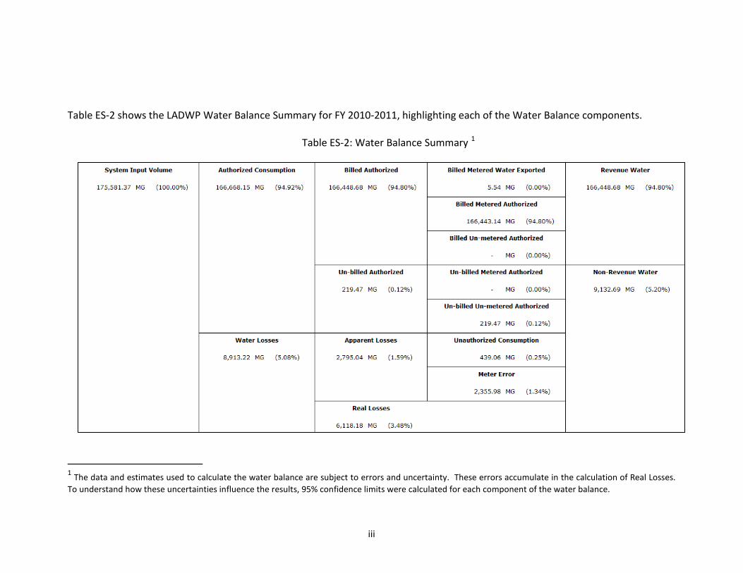
Table ES-2 shows the LADWP Water Balance Summary for FY 2010-2011, highlighting each of the Water Balance components.
Table ES-2: Water Balance Summary 1
1 The data and estimates used to calculate the water balance are subject to errors and uncertainty. These errors accumulate in the calculation of Real Losses. To understand how these uncertainties influence the results, 95% confidence limits were calculated for each component of the water balance.

iv
ES.1.2 Water Loss Performance Indicators With a complete AWWA Water Balance, it is possible to calculate a variety of performance indicators (PI) that further describe the total volumes of real and apparent losses. In the late 1990’s, the IWA initiated a large-scale effort to assess water supply operations, which resulted in the publication of Performance Indicators for Water Supply Services, 2001 (updated in 2006). These performance indicators are now accepted industry-wide as the best way to gain an understanding of how well losses are being managed, and to set targets for reducing water loss.
Table ES-3 describes these performance indicators and provides the performance indicator results calculated for LADWP during FY 2010 – 2011.
Table ES-3: Performance Indicators
Performance Indicator (PI) Description of Use PI for LADWP
FY 2010-2011
Infrastructure Leakage Index (ILI)
The ILI is calculated by comparing the annual volume of Real Losses against an internationally derived standard related to the lowest Real Losses that can be technically achieved for that water system. The methodology takes into account all the factors affecting Real Losses. ILI values close to 1 indicate a water system with very low leakage.
1.26
Real Losses in gallons per service connection per day
This is the preferred basic operational performance indicator for analyzing leakage management performance and one of the most reliable when there are more than 30 services connections per mile, as is the case with the LADWP system.
23.21
Apparent Losses in gallons per service connection per day
This performance indicator is useful for comparing losses against average annual consumption per customer. It can also be used to provide a quick estimate on the value of Apparent Losses when multiplied by an average sales cost for water.
10.60
Non-Revenue Water as a % of System Input Volume
Though this performance indicator is still commonly used in the U.S., it is not a good benchmark for measuring water losses because it is unduly influenced by consumption. For example, if customer demand decreases due to conservation, the percentage of loss will increase even if leakage levels have not changed. This performance indicator should therefore be interpreted with caution.
5.2%
All of the indicators suggest that LADWP’s water distribution system does not have significant volumes of real or apparent losses. Each of the performance indicators reflects a well-performing system in California. However, it is important to take the data quality concerns noted throughout this report into serious consideration before such good performance is regarded as final and accurate. Further, the component analysis of real losses (introduced below) presents useful information on cost-effective proactive measures to reduce real loss volumes even more.
v
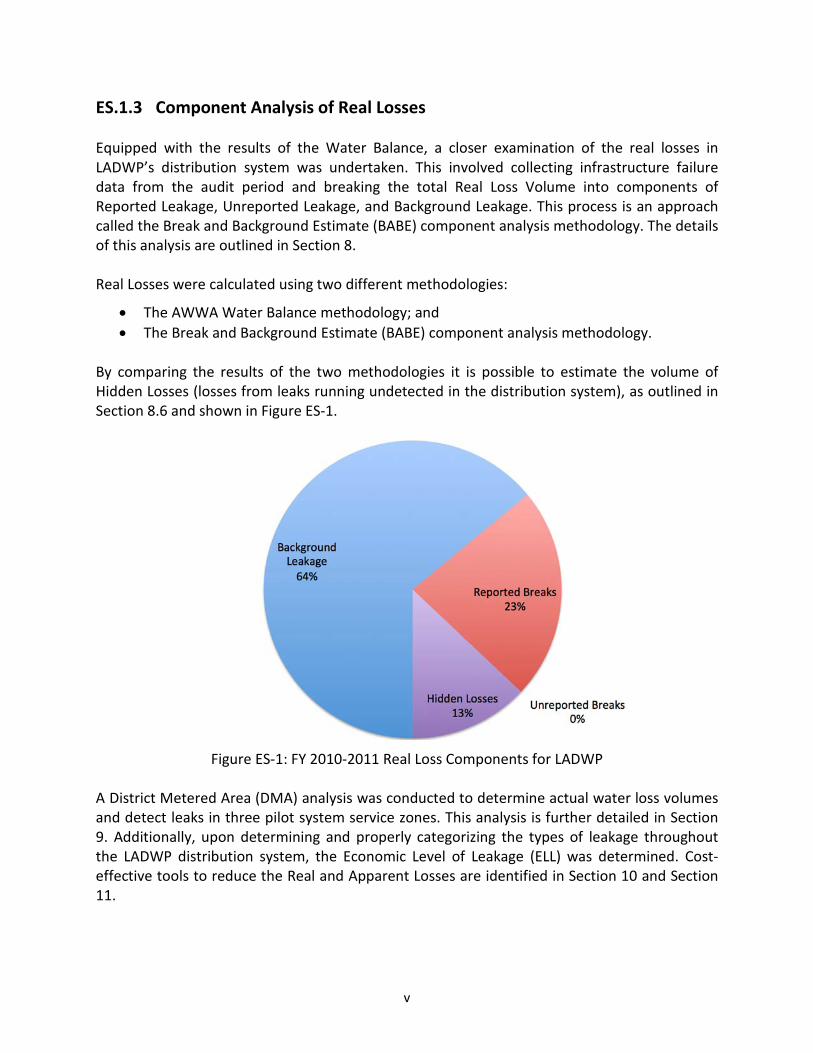
ES.1.3 Component Analysis of Real Losses Equipped with the results of the Water Balance, a closer examination of the real losses in LADWP’s distribution system was undertaken. This involved collecting infrastructure failure data from the audit period and breaking the total Real Loss Volume into components of Reported Leakage, Unreported Leakage, and Background Leakage. This process is an approach called the Break and Background Estimate (BABE) component analysis methodology. The details of this analysis are outlined in Section 8. Real Losses were calculated using two different methodologies:
• The AWWA Water Balance methodology; and • The Break and Background Estimate (BABE) component analysis methodology.
By comparing the results of the two methodologies it is possible to estimate the volume of Hidden Losses (losses from leaks running undetected in the distribution system), as outlined in Section 8.6 and shown in Figure ES-1.
Figure ES-1: FY 2010-2011 Real Loss Components for LADWP
A District Metered Area (DMA) analysis was conducted to determine actual water loss volumes and detect leaks in three pilot system service zones. This analysis is further detailed in Section 9. Additionally, upon determining and properly categorizing the types of leakage throughout the LADWP distribution system, the Economic Level of Leakage (ELL) was determined. Cost-effective tools to reduce the Real and Apparent Losses are identified in Section 10 and Section 11.

vi
ES.2 Findings & Recommendations Each of the following sections includes findings and recommendations for improvement in both future water audit efforts and management of water losses within the LADWP system. ES.2.1 System Input Volume
ES.2.1.1 Findings
Table ES-4 summarizes the main components of the System Input Volume (SIV) for LADWP in FY 2010 – 2011.
Table ES-4: System Input Volume
SYSTEM INPUT VOLUME COMPONENT FY 2010-2011 VOLUME
(MG) (AF)
Los Angeles Aqueduct Filtration Plant 134,056.68 411,404.84
MWD Treated Imports 24,376.16 74,807.70
Groundwater Well Field Production 17,114.66 52,522.96
Microfiltration Plants 33.87 103.93
LA County Waterworks District Exports -5.54 -17.00
TOTAL WATER SUPPLIED (= TOTAL SYSTEM INPUT – EXPORT VOLUME) 175,575.83 538,822.44
Assessment of the Los Angeles Aqueduct Filtration Plant:
The Los Angeles Aqueduct Filtration Plant (LAAFP) volume introduced the greatest amount of uncertainty to the calculation of total SIV. The LAAFP volume includes inflows from the Los Angeles Aqueducts (LAAs) and the LA-35 Metropolitan Water District (MWD) connection. This volume is measured at several different meters that combine to represent the total LAAFP influent and effluent. A wide confidence limit of +/-5.00% was assigned to the volume of LAAFP, which accounted for approximately 76% of the total SIV during the audit period.
It was discovered that the final LAA meters located in Santa Clarita showed a discrepancy between manually-recorded volumes and SCADA readings in May 2011. A comparison of the sum of LAA volumes recorded by these meters and the LA-35 meter versus the influent meters at LAAFP also suggested that the LAA meters are under-registering volume. In addition, process water used at LAAFP is recycled back through the influent meters, further complicating the analysis.
Effluent volume was determined to be a better representation of SIV from LAAFP than influent or LAA volumes. LAAFP effluent volume is split into two branches – treated water from one branch flows into the Van Norman Pumping Station and directly into the distribution system

vii
and water from the other branch is stored in the Los Angeles Reservoir and subsequently released into the distribution system. Currently, two meters account for these volumes – one insertion magnetic meter located on Van Norman Pumping Station branch (known as the “Flow to City” meter), and one ultrasonic meter located at the Los Angeles Reservoir main outlet (known as the “LA Reservoir Outlet” meter). In 2011, two new ultrasonic meters were installed in Vaults 104 and 106, at a split directly downstream of the Flow to City meter; the volume from these two new meters combined represents the same volume from the Flow to City meter. Also in 2011, another new ultrasonic meter was installed in Vault 204 directly south of the LA Reservoir Outlet meter. The data from the old meters (Flow to City and LA Reservoir Outlet) was compared to the new meters (Vaults 104, 106, and 204) and it was determined that the Flow to City meter under-registers by 4.42% and the LA Reservoir Outlet meter under-registers by 0.91%.
Lastly, for approximately 1-2 months annually, the Los Angeles Reservoir main outlet is closed for maintenance. During this time, the West Outlet is used to provide water to the distribution system from the Los Angeles Reservoir. However, the West Outlet connection from the LA Reservoir into the distribution system is not metered. Operations records show that the West Outlet was opened from December 17, 2010 to February 7, 2011 during the audit period. A volume of 3,957.56 MG (or 12,145.31 AF) was estimated for the West Outlet during these two months. Assessment of Purchased Water from Metropolitan Water District:
Installation conditions at seven of the MWD connections to LADWP’s distribution system were examined. It was determined that all of the examined input meters had sufficient upstream and downstream straight lengths (however confirmation of exact setup at LA-5 and the sizes of the LA-17 meters were not provided).
Furthermore, SCADA data for each MWD connection is available in a public database online. For each connection, this data was compared to the billed volumes to guarantee that the volumes used for the water balance corresponded to the operational data on registered flow and did not include financial adjustments. Most all of the billed volumes matched the SCADA totals for the audit period; however, a more significant discrepancy for LA-31 was found and documented. Assessment of Groundwater Wells:
Select meters in each well field were examined to check whether the manufacturer’s installation condition requirements were satisfied. It was determined that none of the well field meters have sufficient straight lengths of pipe to satisfy the manufacturer’s installation conditions. Therefore, it is not guaranteed that any of the well meters perform within the manufacturers’ quoted accuracy ranges.
Additionally, the sum of the individual well meters at Tujunga well field was compared against the outflow meters at the collector basin that leads to the distribution system. The results of this comparison suggest that the well field meters under-register by 5.43%.

viii
ES.2.1.2 Recommendations
1. Use the new meters located in Vaults 104, 106, and 204 for all future calculations of System Input Volumes from LAAFP. These meters are the most accurate representation of LAAFP effluent flow and are closest to the point of distribution system entry. The only volume from LAAFP these do not capture is volume that leaves the LA Reservoir from the West Outlet. LADWP should install a flow meter at this site to accurately and reliably record the volume supplied into the distribution network. Specifically, it is recommended to install an ultrasonic multi-point meter to capture all flow through the West Outlet.
2. Improve the accuracy of metering the well field production. Currently, the installation conditions for the individual well meters will not provide for accurate flow measurement. For each of the well fields, meters installed on the collector line (the pipeline supplying the combined well field production into the distribution network) should meter the total well field production. At some of the well fields such a meter already exists; however, the site inspections showed that these meters are currently not regularly tested and maintained and may also not be sized correctly to capture variable flow volumes. Where necessary new meters should be installed and maintained to accurately capture all flow levels.
3. Consider streamlining the SCADA system organization. For the LAAFP volume analysis alone, data from three separate SCADA systems was required. With different data extraction procedures and permissions for each SCADA system, the data collection process for System Input Volume determination becomes quite cumbersome.
4. Track level data for a complete inventory of reservoirs so that a total increase or decrease in storage volume can be accounted for in the System Input Volume determination.
5. Even though it is recommended to no longer use the LAA meters for the System Input Volume calculation, the LAA SCADA data (from the Northern District Hydrographic Database) and manual reads should be routinely compared on a monthly basis. The difference between manual reads and SCADA data should stay within 0.5%.
6. Routinely compare the MWD billed volumes to the MWD published SCADA totals for each month (available at: https://wins.mwdsc.org/Reports/WAMIReports.aspx).
7. Consider installing a meter at the LA-25 MWD connection to simplify the accuracy assessment process at this site. However, the current setup provides a reasonably accurate volume calculation. Relative to the meter installation at LAAFP, this is not a priority (due to lesser volume and better current accuracy).

ix
ES.2.2 Authorized Consumption
ES.2.2.1 Findings
Table ES-5 summarizes the four main Authorized Consumption components for LADWP in FY 2010 – 2011.
Table ES-5: Authorized Consumption
CONSUMPTION COMPONENT FY 2010-2011 VOLUME
(MG) (AF)
Billed Metered Authorized (Retail Sales) 166,443.14 510,795.24
Billed Un-Metered Authorized Consumption NA NA
TOTAL BILLED AUTHORIZED CONSUMPTION 166,443.14 510,795.24
Un-billed Metered Authorized Consumption NA NA
Un-billed Un-Metered Authorized Consumption 219.47 673.53
TOTAL UN-BILLED AUTHORIZED CONSUMPTION 219.47 673.53
TOTAL AUTHORIZED CONSUMPTION 166,662.61 511,468.77
Billed Metered Authorized Consumption:
Overall, the review of the Billed Metered Authorized Consumption (BMAC) volume determined that the billing system data is in good condition and provides reliable information on consumption volumes. The majority of the BMAC is determined from actual meter readings; only 3.61% of the BMAC was submitted to the billing database as an estimated read.
The water audit process focuses exclusively on the potable water system. As such, all recycled accounts were excluded from the calculation of BMAC. A majority of these accounts are flagged with Rate Code “44”, which represents recycled water, but it was determined that a handful of accounts have a different rate code but still received recycled water. Beyond the Rate Code “44” accounts, an additional 544.95 MG or 1,672.39 AF was excluded from the final BMAC volume determination.
All consumption included in the BMAC volume determination must be accounted for in the System Input Volume. It was determined this is not the case for two accounts that use potable water before the points of measurement for the System Input Volume. These two meters, which track process water at LAAFP, were excluded from the final BMAC volume determination.
In addition, the size of the customer meter was compared to average daily consumption through the meter for all meters in LADWP’s billing system. Several meters were noted to be under-sized or over-sized based on the volumes recorded (see Appendix E). Meter size is stored in two main databases - the Customer Information System (CIS) and the Work Management

x
Information System (WMIS); for this exercise, the size information was retrieved from CIS. A cross-check between CIS and WMIS discovered many inconsistencies between these two databases that need to be addressed. Unbilled Unmetered Authorized Consumption:
Unbilled Unmetered Authorized Consumption volumes, such as system flushing and fire fighting, are not tracked. These volumes were estimated to be 0.125% of the total water supplied by LADWP for FY 2010-2011. ES.2.2.2 Recommendations
1. For the determination of total consumption during the audit period, this analysis suggests that the billing database has reliable and consistent information. However, for use as a meter inventory database, CIS requires a great deal of data cleaning and data integrity improvement (see section ES.2.3 on Apparent Losses).
2. The large number of inaccuracies between WMIS and CIS should be addressed. The current number of inconsistencies could have a big impact on revenue collection and analysis of meter use by size or customer class. Ideally one central database would have up to date information for all meter characteristics and billing data for consumption analysis.
3. For consistency of water audit results from year to year, two groups of accounts should be excluded from the determination of BMAC: all recycled water accounts (Rate Code 44 and additional miscellaneous accounts) and the accounts that receive water before the point of measurement of the System Input Volume.
4. Investigate the meters/accounts highlighted in Appendix E for proper sizing and potential for revenue improvement.
5. Introduce tracking of Unbilled Unmetered Authorized Consumption volumes.
6. For determination of the Unbilled Metered Authorized Consumption, track all of the reservoir levels from first to last day of the audit period in addition to volume estimations for reservoir drainage events.
7. For determination of Unbilled Metered Authorized Consumption, LADWP should further investigate what portion of fire line detector meters register consumption. The manual meter reading exercise carried out in the three trial DMAs has highlighted that a noteworthy number of fire line meters registered consumption over a 7-day period. As an intermediate step, it is recommended that the fire line detector check meters are read on a regular basis. As Automated Meter Reading and Advanced Metering Infrastructure (AMR/AMI) technology is implemented throughout LADWP’s service area, these fire line detector check meters should also be upgraded to be AMR/AMI compatible for easier tracking.

xi
ES.2.3 Apparent Losses
ES.2.3.1 Findings
Table ES-6 summarizes the volumes of Apparent Losses determined for FY 2010–2011.
Table ES-6: Apparent Losses
Apparent Losses Component Annual Volume
(MG)
Annual Volume
(AF)
UNAUTHORIZED CONSUMPTION 439.06 1,347.43
METER DATA HANDLING ERROR 0.00 0.00
CUSTOMER METER UNDER-REGISTRATION SUBTOTAL 2,355.98 7,230.26
Small Customer Meter Under-Registration 1,991.64 6,112.14
Large Customer Meter Under-Registration 364.34 1,118.12
TOTAL APPARENT LOSSES 2,795.04 8,577.69 Small Meter Accuracy Assessment:
A small meter accuracy testing effort was completed to determine the volume of apparent losses due to small meter under-registration. This involved testing 1,073 small meters at multiple flow rates. The results of this testing program indicate that the average accuracy of LADWP’s small meter stock (grouped by size and make) ranges from 84.24% to 99.76%. The 3/4” x 1” meter population test results indicate that the majority of these meters are performing well (presenting an average accuracy of 98.72%). These results are especially notable because the 3/4” x 1” meters make up the majority of the small meter population. Overall, the test results suggest that LADWP’s small meter stock is performing well; 60% of the small meters tested complied with AWWA recommended accuracy limits at all flows, while only 8% of the small meters tested did not comply with the recommended accuracy limits at any flow rate. Of the 1,073 small meters tested, 14 of the meters pulled were completely stuck at all flows.
The apparent loss volume from small meter under-registration was determined to be 1,991.64 MG (or 6,112.14 AF). The largest contributing meter group by size is the 5/8” x 3/4” meter group, which incurred a total of 579.26 MG (or 1,777.69 AF) of apparent losses. Large Meter Accuracy Assessment:
The maintenance of the large meter population was reviewed in depth, and the overhaul schedule was analyzed to optimize replacement frequency according to potential revenue loss due to under-registration. For the purposes of calculating an apparent loss volume for the large meter population during the audit period, an estimated accuracy of 99% was applied to all large meters. This was an assumption informed by the existing large meter testing/replacement program and the overall good performance of the small meter population. For the FY 2010-

xii
2011 an assumed under-registration of 1% results in an apparent loss volume from large meters of 364.34 MG (or 1,118.12 AF). Unauthorized Consumption and Systematic Data Handling Errors:
The amount of Unauthorized Consumption for FY 2010 – 2011 was estimated at 439.06 MG (or 1,347.43), applying the AWWA recommended default value of 0.25% of the Water Supplied. No specific sources of data handling errors were identified in the billing system; therefore, no volume was allocated to this category for FY 2010 – 2011. ES.2.3.2 Recommendations
Recommendations for Reducing Small Meter Under-Registration:
1. The small meter test results indicate that the small meter population is operating at a relatively high level of accuracy. The accuracy results and economic analysis here do not present a case for any immediate action on widespread small meter replacement. However, isolating the worst performing, most economic meter groups (by size and make) for a targeted meter replacement program is recommended. The following small meter groups should be targeted for replacement given that the internal rate of return on the required meter replacement investment was positive:
5/8 x 3/4” Sensus meters 3/4 x 1” Sensus meters 1 1/2” Sensus meters 2” Sensus meters
2. Continue regular testing of random small meter samples (100 to 200 meters per year). Regular testing will allow tracking of the average accuracy of each size/make groups of meters. With this type of monitoring, LADWP will be able to initiate meter replacement when a certain meter make/size group reaches the threshold where meter replacement becomes an economically viable option.
3. The small meter test effort for this analysis revealed inconsistencies in actual meter characteristics and CIS meter records. Improving the data quality on the size, make, and age of meters in the billing database is critical to any meter maintenance program going forward. As the Apparent Loss analysis demonstrates, grouping accuracy test results by meter make and size and aligning these tests with the groups’ annual consumption volumes allows for calculating detailed apparent loss volumes and prioritizing subsets of meters.
4. To best apply small meter test results, it is recommended to pursue consumption profiling research specific to LADWP’s customer base. Volume weighting factors can have significant impact in determining average meter accuracies, influencing all subsequent calculations of apparent losses and economic evaluations of replacement.

xiii
Recommendations for Reducing Large Meter Under-Registration:
1. It is economically infeasible to overhaul each of the 21,250 large meters on a regular basis; it is necessary to identify those meters where potential losses in accuracy would result in the largest losses in revenue generation. It is recommended to rank the large meter population by annual consumption registered by meter.
2. For the large meter population, it is recommended to implement the evaluation approach as outlined in Section 10.2 (comparing annual revenue losses due to under-registration to cost of overhaul) to create prioritized overhaul schedules.
3. Since consumption patterns and consumption volumes of large customers can change over time it is recommended that the overhaul schedule be updated regularly.
4. For the top one hundred large customer meters (ranked by revenue generated), it is recommended to undertake consumption profiling and targeted selection of appropriate metering technology. An improvement of 1% in metering accuracy (achievable by switching from a standard compound meter to an electromagnetic flow meter, for example) will results in significant revenue increases for these meters.
ES.2.3.3 Summary of Recommended Apparent Loss Intervention Strategies
Table ES-7 summarizes the main recommendations for reducing apparent losses to an economically efficient level. It includes a general timeline by fiscal year to provide an overall roadmap for the upcoming five years.
Table ES-7: Apparent Loss Intervention Strategies
Fiscal Year Small Meter Testing
Small Meter Replacement Large Meter Maintenance Unbilled Consumption
FY 2013 – 2014
Ongoing Random Small Meter Testing
Replace targeted size/make meter groups, outlined in Section 10.1
Initiate the overhaul program, as outlined in Section 10.2.4
Read fire service detector checks regularly
FY 2014 – 2015 Begin consumption profiling for highest revenue-generating customers
FY 2015 – 2016 Revisit replacement economics and target revised group of small meters
Pursue meter right-sizing and appropriate technology replacement where necessary
Upgrade fire service detector checks to AMI/AMR for consistent surveillance FY 2016 – 2017
FY 2017 – 2018

xiv
ES.2.4 Real Losses & Component Analysis
ES.2.4.1 Findings
The Water Balance shows that system-wide Real Losses (physical losses from the distribution system) are to be 6,118.18 MG (or 18,776.00 AF) for FY 2010 -2011. The component analysis of Real Losses produced the following results shown in Table ES-8:
Table ES-8: Real Losses
Leakage Component FY 2010-2011 Volume
(MG) (AF)
Background Leakage volume lost through continuously running seeps and drips throughout the system, cannot detect through leak detection
3,917.01 12,020.86
Reported Losses volume lost through failures on mains, service connections, and appurtenances that are reported to LADWP and repaired
1,409.59 4,325.87
Unreported Losses2
volume lost through failures on mains, service connections, and appurtenances that are uncovered through a proactive leak detection survey
0 0
Hidden Losses volume of losses that ran undetected in the system 791.59 2,434.06
Total Real Losses 6,118.18 18,776.00
Assessment of Reported Losses:
To determine the Reported Losses volume, records for all infrastructure failures during the audit period were requested. The process of collecting and analyzing this leak repair data presented notable challenges. Five different database sources provided records that did not consistently have all of the information necessary to determine Reported Leakage (i.e. awareness time of failure, time of repair, size of pipe, type of failure, etc).
With the available data for repairs on mains, LADWP’s main break frequency was determined to be 17 breaks per 100 miles per year. This is less than the average North American break frequency (as determined in a Water Research Foundation Project #4372) of 25 breaks per 100 miles per year. In fact, it approaches the “optimum” break frequency of 15 breaks per 100 miles per year (as determined by another Water Research Foundation Project #4109 on target performance indicators for distribution systems).
With the available data for repairs on service connections, LADWP’s service connection break frequency was determined to be 1.2 breaks per 1,000 service connections per year.
2 As LADWP did not have a pro-active leak detection program in FY 2010-2011, the volume of Unreported Losses is zero.
xv
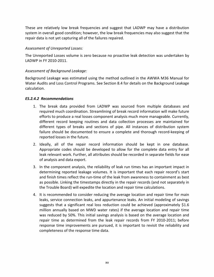
These are relatively low break frequencies and suggest that LADWP may have a distribution system in overall good condition; however, the low break frequencies may also suggest that the repair data is not yet capturing all of the failures repaired. Assessment of Unreported Losses:
The Unreported Losses volume is zero because no proactive leak detection was undertaken by LADWP in FY 2010-2011. Assessment of Background Leakage:
Background Leakage was estimated using the method outlined in the AWWA M36 Manual for Water Audits and Loss Control Programs. See Section 8.4 for details on the Background Leakage calculation. ES.2.4.2 Recommendations
1. The break data provided from LADWP was sourced from multiple databases and required much coordination. Streamlining of break record information will make future efforts to produce a real losses component analysis much more manageable. Currently, different record keeping routines and data collection processes are maintained for different types of breaks and sections of pipe. All instances of distribution system failure should be documented to ensure a complete and thorough record-keeping of reported losses in the future.
2. Ideally, all of the repair record information should be kept in one database. Appropriate codes should be developed to allow for the complete data entry for all leak relevant work. Further, all attributes should be recorded in separate fields for ease of analysis and data export.
3. In the component analysis, the reliability of leak run times has an important impact in determining reported leakage volumes. It is important that each repair record’s start and finish times reflect the run-time of the leak from awareness to containment as best as possible. Linking the timestamps directly in the repair records (and not separately in the Trouble Board) will expedite the location and repair time calculations.
4. It is recommended to consider reducing the average location and repair time for main leaks, service connection leaks, and appurtenance leaks. An initial modeling of savings suggests that a significant real loss reduction could be achieved (approximately $1.6 million annually based on MWD water rates) if the average location and repair time was reduced by 50%. This initial savings analysis is based on the average location and repair time as determined from the leak repair records from FY 2010-2011; before response time improvements are pursued, it is important to revisit the reliability and completeness of the response time data.
xvi
ES.2.5 Field Quantification of Real Losses: District Metered Area & Leak Detection Pilots
ES.2.5.1 Findings
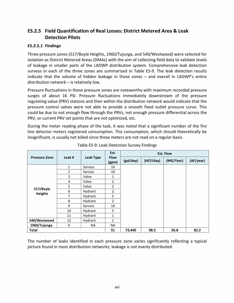
Three pressure zones (517/Boyle Heights, 1960/Tujunga, and 540/Westwood) were selected for isolation as District Metered Areas (DMAs) with the aim of collecting field data to validate levels of leakage in smaller parts of the LADWP distribution system. Comprehensive leak detection surveys in each of the three zones are summarized in Table ES-9. The leak detection results indicate that the volume of hidden leakage in these zones – and overall in LADWP’s entire distribution network – is relatively low.
Pressure fluctuations in these pressure zones are noteworthy with maximum recorded pressure surges of about 16 PSI. Pressure fluctuations immediately downstream of the pressure regulating value (PRV) stations and then within the distribution network would indicate that the pressure control valves were not able to provide a smooth fixed outlet pressure curve. This could be due to not enough flow through the PRVs, not enough pressure differential across the PRV, or current PRV set points that are not optimized, etc.
During the meter reading phase of the task, it was noted that a significant number of the fire line detector meters registered consumption. This consumption, which should theoretically be insignificant, is usually not billed since those meters are not read on a regular basis.
Table ES-9: Leak Detection Survey Findings
Pressure Zone Leak # Leak Type Est.
Flow (gpm)
Est. Flow
(gal/day) (HCF/day) (MG/Year) (AF/year)
517/Boyle Heights
1 Service 10 2 Service 10 3 Valve 1 4 Valve 2 5 Valve 2 6 Hydrant 2 7 Hydrant 5 8 Hydrant 2 9 Service 10
10 Hydrant 5 11 Hydrant 1
540/Westwood 12 Hydrant 1 1960/Tujunga 0 NA NA Total 51 73,440 98.2 26.8 82.2
The number of leaks identified in each pressure zone varies significantly reflecting a typical picture found in most distribution networks; leakage is not evenly distributed.

xvii
ES.2.5.2 Recommendations
Pilot DMA Implementation Recommendations:
1. The selection of appropriate flow meters is crucial for accurate flow measurements in DMAs. It is suggested that for future DMAs permanent meter installations should be considered using turbine or electromagnetic flow meters.
2. If a DMA has multiple feeds it is necessary to consider that during low demand periods (or in some cases, most of the time), some feeds will show only very little demand. This will be the case if one feed takes the lead, supplying the vast majority of DMA demand. As a result, the feeds with low demand do not experience enough flow for the flow meter to record accurately. In these cases the feeds providing very little to no flow should be used as standby feeds, only opening up in case demand in the DMA requires additional supply.
3. All boundary valves and check valves need to be investigated to guarantee that the DMA is hydraulically discrete.
4. Future DMAs should be combined with Advanced Meter Infrastructure (AMI) trial areas for accurate and easily available consumption data.
5. In the effort to comprehensively read all of the meters in each DMA, discrepancies between the meter information in CIS and the actual meters were unveiled. A reliable billing database with up-to-date meter characteristics is an important tool in determining water losses (as demonstrated both for the water loss baseline calculations for each DMA and for the apparent loss analysis).
6. Since LADWP is considering trials of Advanced Metering Infrastructure (AMI), it is recommended that for the pressure zones with AMI, a water loss mass balance is calculated on a regular basis to identify pressure zones with higher levels of leakage that should be targeted for proactive leak detection. The three pressure zones used for the DMA trial should be considered as candidates for trial AMI installation projects.
Pilot Pressure Management Recommendations:
1. At around 82 PSI the average pressure in Zone 540/Westwood is about 10 PSI higher than in the other two pressure zones, which indicates that the average pressure could be reduced further to achieve savings in real losses and extend the infrastructure life span.
2. High frequency pressure logging should be performed in all three pressure zones to assess the full extent of the pressure surges. Necessary steps to avoid pressure surges in the pressure zones should be taken.
Pilot Leak Detection Recommendations:
1. Even though the volume of hidden leakage detected and recovered in these three areas was relatively small, the leak detection pilot has a simple payback period of 0.8 years (about 10 months), indicating that proactive leak detection is an economically viable water loss control strategy for LADWP.
xviii
ES.2.6 Economically Efficient Intervention Strategies to Reduce Real Losses
ES.2.6.1 Findings
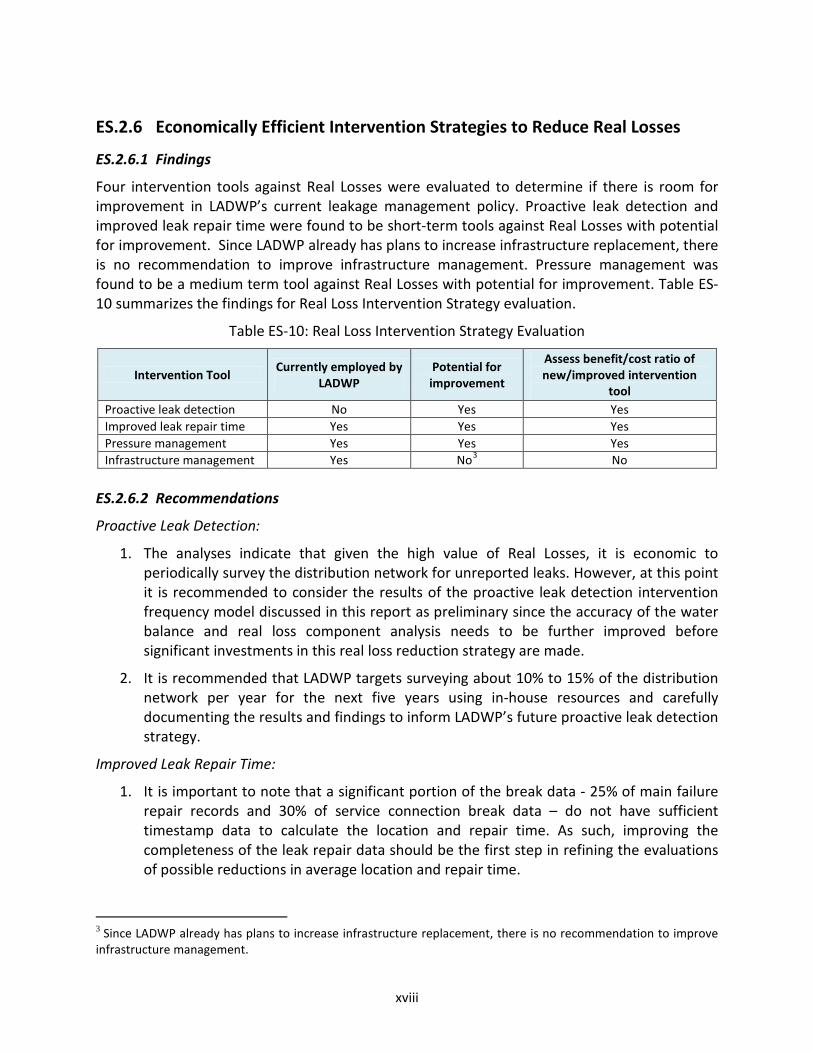
Four intervention tools against Real Losses were evaluated to determine if there is room for improvement in LADWP’s current leakage management policy. Proactive leak detection and improved leak repair time were found to be short-term tools against Real Losses with potential for improvement. Since LADWP already has plans to increase infrastructure replacement, there is no recommendation to improve infrastructure management. Pressure management was found to be a medium term tool against Real Losses with potential for improvement. Table ES-10 summarizes the findings for Real Loss Intervention Strategy evaluation.
Table ES-10: Real Loss Intervention Strategy Evaluation
Intervention Tool Currently employed by LADWP
Potential for improvement
Assess benefit/cost ratio of new/improved intervention
tool Proactive leak detection No Yes Yes Improved leak repair time Yes Yes Yes Pressure management Yes Yes Yes Infrastructure management Yes No3 No
ES.2.6.2 Recommendations
Proactive Leak Detection:
1. The analyses indicate that given the high value of Real Losses, it is economic to periodically survey the distribution network for unreported leaks. However, at this point it is recommended to consider the results of the proactive leak detection intervention frequency model discussed in this report as preliminary since the accuracy of the water balance and real loss component analysis needs to be further improved before significant investments in this real loss reduction strategy are made.
2. It is recommended that LADWP targets surveying about 10% to 15% of the distribution network per year for the next five years using in-house resources and carefully documenting the results and findings to inform LADWP’s future proactive leak detection strategy.
Improved Leak Repair Time:
1. It is important to note that a significant portion of the break data - 25% of main failure repair records and 30% of service connection break data – do not have sufficient timestamp data to calculate the location and repair time. As such, improving the completeness of the leak repair data should be the first step in refining the evaluations of possible reductions in average location and repair time.
3 Since LADWP already has plans to increase infrastructure replacement, there is no recommendation to improve infrastructure management.

xix
2. Reducing the average location and repair time on mains failures by 50%, would save about 472 MGY (or 1,448.61 AFY), resulting in a cost savings of $1,227,425 (using the MWD Tier 1 rate). The assumed reduction of average location and repair time by 50% was used to get an initial idea of the potential savings that could be achieved. Before a substantial recommendation can be made on a target location and repair time for main failures, the currently available leak repair data needs to be substantially improved in terms of data quality/availability.
3. Reducing the average location and repair time on service connection failures by 60% would save about 157 MGY (or 481.82 AFY), resulting in a cost savings of $409,029. This indicates significant potential for real loss and cost savings. The assumed reduction of average location and repair time by 60% was used to get an initial idea of the potential savings that could be achieved. Before a substantial recommendation can be made on a target location and repair time for service line failures, the currently available leak repair data needs to be substantially improved in terms of data quality/availability.
Pressure Management:
1. It is recommended to follow the three-step process outlined in Section 11 to achieve the pressure reductions that would produce an estimated annual savings of $1,414,000 per year (by reducing losses by 544 MGY or 1,669.47 AFY).
2. It is recommended that LADWP implement a small pressure monitoring pilot (5 to 10 pressure zones) over the first 12 months of the pressure management program before implementing Step 1 over the next 36 months, followed by Step 2 over the next 48 months and Step 3 over the subsequent 48 months (see Section 11.4 for details on each Step).
3. Demand-based pressure control should be investigated as an option to optimize the current pressure management scheme in each pressure zone.

xx
ES.2.6.3 Summary of Recommendations for Real Loss Intervention Strategies
Table ES-11 summarizes the main recommendations for reducing real losses to an economically efficient level. It includes a general timeline by fiscal year to provide an overall roadmap for the upcoming five years.
Table ES-11: Recommendations for Reduction of Real Losses
Fiscal Year Proactive Leak Detection Improved Location and Repair Times for Reported Leaks
Pressure Management Program
FY 2013 – 2014 Prepare for implementation of proactive leak detection program
Focus on collection of better leak repair data
Prepare for implementation of pressure monitoring pilot
in 5 to 10 pressure zones
FY 2014 – 2015 Detailed leak detection in 10% to 15% of the distribution network
using LADWP leak detection staff
Focus on collection of better leak repair data
Implement Step 1 of the pressure management program as detailed in
Section 11.4.2
FY 2015 – 2016 Detailed leak detection in 10% to 15% of the distribution network
using LADWP leak detection staff
Update analysis on improved location and repair times and
evaluate the necessary additional budget for reducing the average location and repair time for reported mains leaks
FY 2016 – 2017 Detailed leak detection in 10% to 15% of the distribution network
using LADWP leak detection staff
If found cost effective Deploy additional repair crews to
reduce average location and repair times to optimum levels
FY 2017 – 2018 Detailed leak detection in 10% to 15% of the distribution network
using LADWP leak detection staff
Implement Step 2 of the pressure management program as detailed in
Section 11.4.2
FY 2018– 2019 Detailed leak detection in 10% to 15% of the distribution network
using LADWP leak detection staff
FY 2019 – 2020 Evaluate results of detailed leak detection efforts and update strategy according to findings over past 4 years
FY 2020 – 2021 Implement updated proactive leak
detection strategy and if/where AMI is implemented utilize AMI and SCADA data for prioritizing
areas for ongoing leak detection based on calculated leakage loss
levels by pressure zone
FY 2021 – 2022
Implement Step 3 of the pressure management program as detailed in
Section 11.4.2
FY 2023 – 2024
FY 2024 – 2025
FY 2025 – 2026

TASK FORCE
WATER LOSS
National Leaders in Water Loss Prevention
ACTIO
N PLA
N
September 2015
Water Systems Optimization, Inc.
In Partnership With
smarcu
Typewritten Text
Attachment 2
smarcu
Typewritten Text
smarcu
Typewritten Text
smarcu
Typewritten Text

Pageii

ACTION PLAN
Pageiii
Acknowledgements
We would like to thank the Water Loss Task Force for all of their work in completing this Action Plan.
Mario Acevedo Martin Adams Edgardo Agustin Greg Algorri Jaime Almaraz Greg Ammon Shabbir Baldiwala Darlene Battle Alvin Bautista Jeff Bray Joe Castruita Flora Chang Dave Christensen Phil Clark Steven Cole Anselmo Collins Clinetta Collins John Cox Donald Cresse Kevin Daugherty Carlos De La Roca Charnpreet Dhillon Mike Downs Peter Dugan Penny Falcon Amgad Farag Patrick Findley Kate Gasner
Albert Gastelum Brian Gibson Ricky Glover Priscilla Gonzalez Mike Grahek Sharon Grove Mona Guirguis Richard Harasick Kathie Hirata Cree Horner Greg Hornsby Simon Hsu Todd Huynh Jeff Kauf Terri Koch Delon Kwan Jevon Lam Matt Lampe Todd Le David Leonard Jonathan Leung Andrew Linard Breonia Lindsey Greg Loveland Carolina Maldonado Sal Mancilla Raz Manoukian Sofia Marcus
Jose Martinez George Mavrakis Mike Miller Vee Miller Charles Ngo Ehinomen Nwani John Otoshi Annamae Peji Adam Perez Marce‐Adrian Perez David Pettijohn Linh Phan Russ Pierson Cliff Plumb Ethelinda Reyes Gonzalo Reyes Vincent Rivera Earl Rodgers George Rofail Javier Romero Susan Rowghani Stefan Sadeli Adolfo Sanchez Paul Scantlin Vlad Scutelnicu Guillermo Serrano Keith Session Minas Sirakie
Ani Siyahian Tim Spinn Reinhard Sturm Salman Sufi Dean Terada Eric Tillemans Robert Tokashiki Jordan Tolle Hugo Torres Mark Townsend Du Tran Stephan Tucker Craig Underwood Kim Versluis Bill Van Wagoner Greg Van Nance Walker‐Bonnelli Julie Wang Gary Warden Gloria Williams Wayne Wohler David Wright Kathy Wright James Yannotta Miki Yonamine George Zordilla

WATER LOSS TASK FORCE
Pageiv

ACTION PLAN
Pagev
TableofContents
Acknowledgements ...................................................................................................................................... iii
Table of Contents .......................................................................................................................................... v
List of Acronyms and Abbreviations ............................................................................................................. x
Executive Summary ....................................................................................................................................... 1
Background ................................................................................................................................................... 3
Organization of this Report ........................................................................................................................... 7
Section 1: System Input Volume ................................................................................................................... 9
Recommendation 1.1: LA Aqueduct Filtration Plant System Input Volume Meters ................................. 9
Recommendation 1.2: LA Reservoir West Outlet Meter Installation ...................................................... 14
Recommendation 1.3: Well Field Meter Accuracy and Regular Testing ................................................. 17
Recommendation 1.4: Storage Data Tracking ........................................................................................ 25
Recommendation 1.5: MWD LA‐25 Connection Meter Installation ....................................................... 28
Section 2: Database Management .............................................................................................................. 33
Recommendation 2.1: Water Control Systems Database Consolidation ............................................... 33
Recommendation 2.2: Recycled Water and Treatment Process Water Tracking ................................... 37
Recommendation 2.3: CIS and WMIS Inconsistencies ............................................................................ 41
Recommendation 2.4: Leak Database Consolidation and Accuracy....................................................... 45
Section 3: Meter Testing and Replacement ................................................................................................ 51
Recommendation 3.1: Customer Meter Sizing and Regular Consumption Profiling .............................. 51
Recommendation 3.2: Testing of Small Customer Meters ..................................................................... 54
Recommendation 3.3: Replacement of Worst Performing Small Customer Meters .............................. 59
Recommendation 3.4: Large Meter Maintenance Schedule Overhaul ................................................... 62
Section 4: Leak Detection and Prevention .................................................................................................. 65
Recommendation 4.1: Pressure Management Improvement and Pilot Study ....................................... 67
Recommendation 4.2: Leak Location and Repair Time Reduction ......................................................... 79
Recommendation 4.3: Active Leak Detection ......................................................................................... 85
Section 5: Unmetered and Unauthorized Consumption ............................................................................ 91
Recommendation 5.1: Unauthorized Consumption Volume Tracking .................................................... 91

WATER LOSS TASK FORCE
Pagevi
Recommendation 5.2: Authorized Unmetered Uses Tracking ................................................................ 98
Conclusion ................................................................................................................................................. 103
Appendix ................................................................................................................................................... 105
ListofTables
Table 1: FY 2010‐2011 Performance Indicators ............................................................................................ 5
Table 2: Estimated Cost for Recommendation 1.1, Action 1 ...................................................................... 13
Table 3: Estimated Time for Recommendation 1.1, Action 1 ..................................................................... 13
Table 4: Estimated Cost for Recommendation 1.1, Action 2 ...................................................................... 14
Table 5: Estimated Time for Recommendation 1.1, Action 2 ..................................................................... 14
Table 6: Estimated Cost for Recommendation 1.2, Action 1 ...................................................................... 16
Table 7: Estimated Time for Recommendation 1.2, Action 1 ..................................................................... 16
Table 8: Summary of Flow Meters & Connectivity at LADWP Well Fields .................................................. 18
Table 9: Estimated Cost for Recommendation 1.3, Action 1 ...................................................................... 21
Table 10: Estimated Time for Recommendation 1.3, Action 1 ................................................................... 21
Table 11: Estimated Cost for Recommendation 1.3, Action 2 .................................................................... 22
Table 12: Estimated Time for Recommendation 1.3, Action 2 ................................................................... 22
Table 13: Manufacturer’s Flow Meter Calibration Requirements .............................................................. 23
Table 14: Estimated Cost for Recommendation 1.3, Action 3 .................................................................... 24
Table 15: Estimated Time for Recommendation 1.3, Action 3 ................................................................... 24
Table 16: Major Reservoirs and Tanks ........................................................................................................ 25
Table 17: Estimated Cost for Recommendation 1.4, Action 1 .................................................................... 27
Table 18: Estimated Time for Recommendation 1.4, Action 1 ................................................................... 27
Table 19: Volume of Treated Water Billed from MWD LA‐25 .................................................................... 28
Table 20: Estimated Cost for Recommendation 1.5, Action 1 .................................................................... 29
Table 21: Estimated Time for Recommendation 1.5, Action 1 ................................................................... 30
Table 22: Estimated Cost for Recommendation 1.5, Action 2 .................................................................... 31
Table 23: Estimated Time for Recommendation 1.5, Action 2 ................................................................... 31
Table 24: LADWP Water Control Systems .................................................................................................. 34
Table 25: Estimated Cost for Recommendation 2.1, Action 1 .................................................................... 35
Table 26: Estimated Time for Recommendation 2.1, Action 1 ................................................................... 35

ACTION PLAN
Pagevii
Table 27: Estimated Cost for Recommendation 2.1, Action 2 .................................................................... 36
Table 28: Estimated Time for Recommendation 2.1, Action 2 ................................................................... 36
Table 29: Estimated Cost for Recommendation 2.2, Action 1 .................................................................... 40
Table 30: Estimated Time for Recommendation 2.2, Action 1 ................................................................... 40
Table 31: Estimated Cost for Recommendation 2.2, Action 2 .................................................................... 41
Table 32: Estimated Time for Recommendation 2.2, Action 2 ................................................................... 41
Table 33: Number of Cross‐Database Discrepancies Checked During CISCON .......................................... 43
Table 34: Estimated Cost for Recommendation 2.3, Action 1 .................................................................... 44
Table 35: Estimated Time for Recommendation 2.3, Action 1 ................................................................... 45
Table 36: Main Leaks Data Quality ............................................................................................................. 46
Table 37: Service Leaks Between Main and Curb Data Quality .................................................................. 47
Table 38: Service Leaks Between Curb and Meter Box Data Quality ......................................................... 47
Table 39: Estimated Cost for Recommendation 2.4, Action 1 .................................................................... 49
Table 40: Estimated Time for Recommendation 2.4, Action 1 ................................................................... 49
Table 41: Estimated Cost for Recommendation 3.1, Action 1 .................................................................... 53
Table 42: Estimated Time for Recommendation 3.1, Action 1 ................................................................... 54
Table 43: Estimated Cost for Recommendation 3.2, Action 1 .................................................................... 56
Table 44: Estimated Time for Recommendation 3.2, Action 1 ................................................................... 57
Table 45: Estimated Cost for Recommendation 3.2, Action 2 .................................................................... 58
Table 46: Estimated Time for Recommendation 3.2, Action 2 ................................................................... 58
Table 47: Estimated Cost for Recommendation 3.3, Action 1 .................................................................... 61
Table 48: Estimated Time for Recommendation 3.3, Action 1 ................................................................... 61
Table 49: Estimated Cost for Recommendation 3.4, Action 1 .................................................................... 64
Table 50: Estimated Time for Recommendation 3.4, Action 1 ................................................................... 64
Table 51: Estimated Cost for Recommendation 4.1, Action 1 .................................................................... 73
Table 52: Estimated Time for Recommendation 4.1, Action 1 ................................................................... 74
Table 53: Estimated Cost for Recommendation 4.1, Action 2 .................................................................... 75
Table 54: Estimated Time for Recommendation 4.1, Action 2 ................................................................... 75
Table 55: Estimated Cost for Recommendation 4.1, Action 3 .................................................................... 76
Table 56: Estimated Time for Recommendation 4.1, Action 3 ................................................................... 76
WATER LOSS TASK FORCE
Pageviii
Table 57: Estimated Cost for Recommendation 4.1, Action 4 .................................................................... 77
Table 58: Estimated Time for Recommendation 4.1, Action 4 ................................................................... 77
Table 59: Estimated Cost for Recommendation 4.1, Action 5 .................................................................... 78
Table 60: Estimated Time for Recommendation 4.1, Action 5 ................................................................... 78
Table 61: Summary of Economic Analysis of Improved Location and Repair Times for Main Line Failures
.................................................................................................................................................................... 80
Table 62: Summary of Economic Analysis of Improved Location and Repair Times for Service Lines Failure
and Meter Leaks ......................................................................................................................................... 80
Table 63: Estimated Cost for Recommendation 4.2, Action 1 .................................................................... 83
Table 64: Estimated Time for Recommendation 4.2, Action 1 ................................................................... 83
Table 65: Estimated Cost for Recommendation 4.2, Action 2 .................................................................... 84
Table 66: Estimated Time for Recommendation 4.2, Action 2 ................................................................... 84
Table 67: Estimated Cost for Recommendation 4.3, Action 1 .................................................................... 86
Table 68: Estimated Time for Recommendation 4.3, Action 1 ................................................................... 86
Table 69: Estimated Cost for Recommendation 4.3, Action 2 .................................................................... 87
Table 70: Estimated Time for Recommendation 4.3, Action 2 ................................................................... 87
Table 71: Estimated Cost for Recommendation 4.3, Action 3 .................................................................... 89
Table 72: Estimated Time for Recommendation 4.3, Action 3 ................................................................... 89
Table 73: Estimated Cost for Recommendation 4.3, Action 4 .................................................................... 90
Table 74: Estimated Time for Recommendation 4.3, Action 4 ................................................................... 90
Table 75: Estimated Cost for Recommendation 5.1, Action 1 .................................................................... 94
Table 76: Estimated Time for Recommendation 5.1, Action 1 ................................................................... 95
Table 77: Estimated Cost for Recommendation 5.1, Action 2 .................................................................... 96
Table 78: Estimated Time for Recommendation 5.1, Action 2 ................................................................... 96
Table 79: Estimated Cost for Recommendation 5.1, Action 3 .................................................................... 97
Table 80: Estimated Time for Recommendation 5.1, Action 3 ................................................................... 97
Table 81: Estimated Cost for Recommendation 5.2, Action 1 .................................................................. 100
Table 82: Estimated Time for Recommendation 5.2, Action 1 ................................................................. 100
Table 83: Estimated Cost for Recommendation 5.2, Action 2 .................................................................. 101
Table 84: Estimated Time for Recommendation 5.2, Action 2 ................................................................. 101
ACTION PLAN
Pageix
Table 85: Summary of Recommended Actions ......................................................................................... 103
Table 86: List of Sections, Recommended Actions, and Key LADWP Staff ............................................... 105
ListofFigures
Figure 1: Standardized Components of the Annual Water Balance (Not to Scale) ...................................... 3
Figure 2: System Input Volume Identified in the Water Balance (Not to Scale)........................................... 9
Figure 3: Schematic of Meters Tracking Supply Volumes at LAAFP ............................................................ 10
Figure 4: LA‐25 Volume Determination Mass Balance ............................................................................... 28
Figure 5: Billed Metered Authorized Consumption Identified in the Water Balance (Not to Scale) .......... 37
Figure 6: Diagram Showing Classification of Leak Types A, B, & C ............................................................. 45
Figure 7: Customer Meter Inaccuracies Identifed in the Water Balance (Not to Scale)............................. 51
Figure 8: Real Losses Identified in the Water Balance (Not to Scale) ......................................................... 65
Figure 9: Four‐Component Tool Box for Intervention against Real Losses................................................. 66
Figure 10: Static Pressure Map of LADWP’s Water System ........................................................................ 70
Figure 11: Leak Density Map of LADWP’s Water System ........................................................................... 71
Figure 12: Ground Elevation Map of LADWP’s Water System .................................................................... 72
Figure 13: Seasonal Variation of Leaks in LADWP’s Water System ............................................................ 81
Figure 14: Unmetered and Unauthorized Consumption Identified in the Water Balance (Not to Scale) .. 91

WATER LOSS TASK FORCE
Pagex
ListofAcronymsandAbbreviations
AF: Unit of Volume in Acre‐Feet
AFY: Unit of Acre‐Feet per Year
AMG: Asset Management Group
AMI: Advanced Metering Infrastructure
AWWA: American Water Works Association
AWWA M6: AWWA’s Manual on Selection, Installation, Testing and Maintenance of Water Meters
AWWA M36: AWWA’s Manual on Water Audits and Loss Control Programs
BEM: Broadband Electromagnetic
BMAC: Billed Metered Authorized Consumption
BMP: Best Management Practice
CCB: Customer Care & Billing
CIS: Customer Information System, also known as CIS/TRES or TRES
CISCON: CIS Conversion to CCB
COBOL: Common Business Oriented Language
CPS: Construction Productivity System
CSD: Customer Services Division
CUWCC: California Urban Water Conservation Council
DCS: Distributed Control System
DWP: See LADWP
DWR: California Department of Water Resources
ERT: Encoder Receiver Transmitter
F/A: Field Activity
FI: Field Investigation
FPS: Unit of Velocity in Feet per Second
FY: Fiscal Year
GIS: Geographic Information Systems
GPM: Unit of Flow in Gallons per Minute
HCF: Unit of Volume in Hundred Cubic Feet
ACTION PLAN
Pagexi
ILI: Infrastructure Leakage Index
ITS: Information Technology Services Division
IWA: International Water Association
JPI: Jensen Plant Inlet
LA: Los Angeles
LAA: Los Angeles Aqueduct (of which there are two: LAA 1 and LAA 2)
LAAFP: Los Angeles Aqueduct Filtration Plant
LABSS: Los Angeles Bureau of Street Services
LADBS: Los Angeles Department of Building and Safety
LADWP: Los Angeles Department of Water and Power, also referenced as the Department or DWP
LAFD: Los Angeles Fire Department
LAPD: Los Angeles Police Department
LAR: Los Angeles Reservoir
LARIAC: Los Angeles Region Imagery Acquisition Consortium
LAWSDAC: Los Angeles Water System Data Acquisition and Control
MA: Management Analyst
M&C: Maintenance & Construction
MDT: Mobile Data Terminal
MG: Unit of Volume in Millions of Gallons
MGY: Unit of Millions of Gallons per Year
MOU: Memorandum of Understanding
MRP: Meter Replacement Program
MWD: Metropolitan Water District of Southern California
NIST: National Institute of Standards and Technology
O&M: Operations & Maintenance
OTS: Operational Technology System
PLC: Programmable Logic Controller
PRV: Pressure Regulating Valve
PSI: Unit of pressure in pounds per square inch
R&C: Repair and Construction

WATER LOSS TASK FORCE
Pagexii
RF: Radio Frequency
RSU: Revenue Security Unit
RTU: Remote Terminal Unit
SCADA: Supervisory Control and Data Acquisition
SFO: Sepulveda Feeder Outlet
SIM: Subscriber Identification Module
TOCC: Treatment Operations Control Center
TRES: See CIS
UCLA: University of California Los Angeles
ULARA: Upper Los Angeles River Area
UME: Unitized Measuring Elements
USA: Underground Service Alert
UV: Ultraviolet
UWMP: Urban Water Management Plan
VGS: Valley Generating Station
WDD: Water Distribution Division
WETS: Water Engineering & Technical Services Division
WIR: Water Investigation Report
WMIS: Work Management Information System
WOD: Water Operations Division
WRD: Water Resources Division
WRF: Water Research Foundation
WSO: Water Systems Optimization, Inc.
WTCS: Water Technology and Control Systems

ACTION PLAN
Page1
ExecutiveSummary
This Action Plan was prepared by LADWP’s Water Loss Task Force (Task Force) and approved by LADWP
management. The purpose of this Action Plan is to assess the recommendations presented in the Water
Loss Audit and Component Analysis study completed in 2013 and conducted by Water Systems
Optimization, Inc. consultants in conjunction with LADWP staff. The Action Plan includes an assessment
of feasibility, cost‐effectiveness, and other benefits associated with implementation of the
recommendations, as well as a determination of how the recommendations may improve LADWP’s
Water System efficiency and meet State of California regulatory requirements related to system water
losses. These regulatory requirements – such as California Urban Water Conservation Council (CUWCC)
Best Management Practice (BMP) Reporting, Assembly Bill 1420, Senate Bill 1420, and Senate Bill 555 –
are discussed in the Background section of this Action Plan.
LADWP’s Task Force consists of over 100 staff from the following eight divisions:
Customer Services Division (CSD)
Information Technology Services Division (ITS)
Security Services Division (SSD)
Water Distribution Division (WDD)
Water Engineering & Technical Services Division (WETS)
Water Operations Division (WOD)
Water Quality Division (WQD)
Water Resources Division (WRD)
The Action Plan was coordinated by the Water Resources Division Water Conservation Policy Group.
Water Systems Optimization, Inc. served as consulting technical experts and provided guidance to the
key staff during the drafting of the Action Plan. Key LADWP staff who worked on the write‐up for each
section of this Action Plan are shown in the Appendix.
A summary of recommended actions to reduce water losses in LADWP’s water distribution system and
improve the validity of data in the annual LADWP water loss audit are presented in the Conclusion
section of this Action Plan. Overall it is estimated that the recommended actions will cost just over $4
million in capital costs and just under $2 million in operations and maintenance costs.

WATER LOSS TASK FORCE
Page2
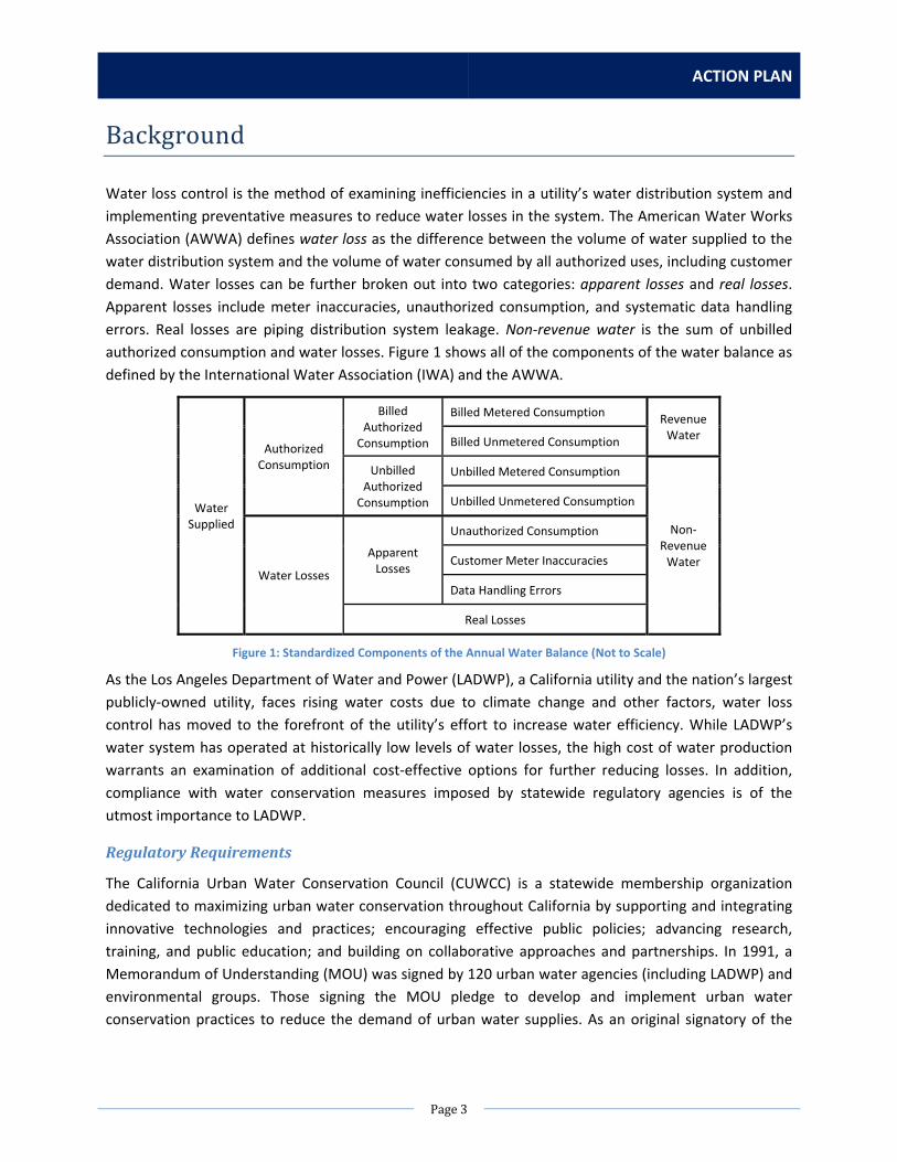
ACTION PLAN
Page3
Background
Water loss control is the method of examining inefficiencies in a utility’s water distribution system and
implementing preventative measures to reduce water losses in the system. The American Water Works
Association (AWWA) defines water loss as the difference between the volume of water supplied to the
water distribution system and the volume of water consumed by all authorized uses, including customer
demand. Water losses can be further broken out into two categories: apparent losses and real losses.
Apparent losses include meter inaccuracies, unauthorized consumption, and systematic data handling
errors. Real losses are piping distribution system leakage. Non‐revenue water is the sum of unbilled
authorized consumption and water losses. Figure 1 shows all of the components of the water balance as
defined by the International Water Association (IWA) and the AWWA.
Water Supplied
Authorized Consumption
Billed Authorized Consumption
Billed Metered Consumption Revenue Water
Billed Unmetered Consumption
Unbilled Authorized Consumption
Unbilled Metered Consumption
Non‐Revenue Water
Unbilled Unmetered Consumption
Water Losses
Apparent Losses
Unauthorized Consumption
Customer Meter Inaccuracies
Data Handling Errors
Real Losses
Figure 1: Standardized Components of the Annual Water Balance (Not to Scale)
As the Los Angeles Department of Water and Power (LADWP), a California utility and the nation’s largest
publicly‐owned utility, faces rising water costs due to climate change and other factors, water loss
control has moved to the forefront of the utility’s effort to increase water efficiency. While LADWP’s
water system has operated at historically low levels of water losses, the high cost of water production
warrants an examination of additional cost‐effective options for further reducing losses. In addition,
compliance with water conservation measures imposed by statewide regulatory agencies is of the
utmost importance to LADWP.
RegulatoryRequirements
The California Urban Water Conservation Council (CUWCC) is a statewide membership organization
dedicated to maximizing urban water conservation throughout California by supporting and integrating
innovative technologies and practices; encouraging effective public policies; advancing research,
training, and public education; and building on collaborative approaches and partnerships. In 1991, a
Memorandum of Understanding (MOU) was signed by 120 urban water agencies (including LADWP) and
environmental groups. Those signing the MOU pledge to develop and implement urban water
conservation practices to reduce the demand of urban water supplies. As an original signatory of the
WATER LOSS TASK FORCE
Page4
MOU, LADWP has remained in compliance with all Best Management Practices (BMP) for water
conservation as required by the CUWCC.
In 2009, the CUWCC amended the MOU to include new requirements for BMP 1.2: Water Loss Control.
The revised BMP requires an annual water loss audit of the water system using the AWWA Free Water
Audit Software, and the completion of a component analysis of real losses every 4 years. The first year
of implementation for the annual audit was the fiscal year July 1, 2009 to June 30, 2010 and the first
component analysis was due on June 30, 2013. The MOU stipulates that implementation of BMP 1.2
shall consist of the following:
1. Standard Water Audit and Water Balance ‐ Agencies are required to quantify their current
volume of water loss, and complete an annual standard water audit using AWWA water loss
software.
2. Validation ‐ Agencies are required to develop a validated set of data for all entries of their
water audit and balance, and data validation shall follow the methods suggested by the
AWWA.
3. Economic Values ‐ The economic value of real loss recovery shall be based upon the
agency’s avoided cost of water as calculated by the CUWCC’s Avoided Cost Model, or
another agency model consistent with the CUWCC model.
4. Component Analysis ‐ A component analysis is required at least once every four years and is
defined as a means to analyze losses and their causes by quantity and type.
With the passage of California Assembly Bill 1420 in 2009, compliance with the CUWCC BMPs is
mandatory for a water agency to qualify for state grants and loans.
The Department of Water Resources (DWR) is another statewide agency responsible for managing and
protecting California’s water. All BMP compliance reports submitted to CUWCC are also sent to DWR.
With the passage of the Urban Water Management Planning Act in 1984, all urban water suppliers in
California must prepare and adopt an Urban Water Management Plan (UWMP) every five years and
submit the final UWMP to DWR. In 2014, California Senate Bill 1420 was passed amending the Urban
Water Management Planning Act to require UWMPs to quantify and report on distribution system
losses. The 2015 UWMP will be the first UWMP to be submitted under this new requirement.
Another bill, California Senate Bill 555, focuses on water loss validation. The bill requires that each water
supplier submit a validated water loss audit to the State each year using AWWA water audit software
under the guidance of the AWWA M36 Manual and DWR requirements. In order to validate the water
loss audit report, the water supplier must solicit a technical expert to confirm the basis of all of the
entries in the report. The bill further requires water suppliers to report on steps taken each year to
increase the validity of the data entered into the audit. Additionally, the State Water Resources Control
Board is tasked in the bill with adopting rules before July 1, 2020 requiring urban retail water suppliers
to meet performance standards for the volume of water losses. The bill has been approved by the
California Senate and is expected to be approved by the California Assembly this year. Therefore, the bill
would be effective in 2015. The first validated water loss audit report will be due on October 1, 2017.

ACTION PLAN
Page5
FiscalYear2010‐2011WaterLossAuditandComponentAnalysis
LADWP has been tracking its non‐revenue water totals going back to 1980 and adopted the AWWA M36
Water Loss Control methods in 2009. From April 2012 to June 2013, LADWP conducted its most‐
comprehensive Water Loss Audit and Component Analysis. (The Final Report can be downloaded at
http://www.ladwp.com/wc.) The audit period examined was the fiscal year (FY) from July 1, 2010 to
June 30, 2011 (FY 2010‐2011). For this project, Water Systems Optimization (WSO), a consultant hired
by LADWP and a technical expert in the field of water loss control, examined the efficiency of LADWP’s
water distribution system. Specifically, WSO investigated the current ability to accurately identify real
and apparent losses, determined the economic optimum level of water losses, and identified,
prioritized, and recommended the most efficient and cost‐effective loss intervention strategies to
minimize water loss.
A Water Conservation Field Services Program Grant in the amount of $100,000 was received from the
United States Bureau of Reclamation to partially fund contract costs for the project. The goal of the
project was to fulfill all of the coverage requirements of the amended BMP 1.2 in the CUWCC MOU. The
project investigated systematic data of LADWP’s facilities and infrastructure related to water losses and
provided recommendations for decreasing or eliminating such losses.
Upon completion of the project it was possible to calculate a variety of performance indicators (PI).
These performance indicators are standards accepted industry‐wide as the best way to understand how
water losses are being managed, and to set targets for reducing those losses. Table 1 provides
performance indicators for LADWP during FY 2010‐2011.
Table 1: FY 2010‐2011 Performance Indicators
Performance Indicator
(PI) Description of Use
PI for LADWP
FY 2010‐2011
Infrastructure Leakage
Index (ILI)
ILI values close to 1 indicate a water system with very low
leakage. The ILI is calculated by comparing the annual volume of
Real Losses against a standard quantifying the lowest Real
Losses achievable for the Water System.
1.26
Real Losses in gallons
per service connection
per day
This is the preferred basic operational performance indicator for
analyzing leakage management performance and one of the
most reliable.
23.21
Apparent Losses in
gallons per service
connection per day
This performance indicator is useful for comparing losses against
average annual consumption per customer. 10.60
Non‐Revenue Water as
a % of Water Supplied
Though this performance indicator is still commonly used, it is
not a good benchmark for measuring losses because it is unduly
influenced by consumption. For example, if customer demand
decreases due to conservation, the percentage of loss will
increase even if leakage levels have not changed.
5.2%
WATER LOSS TASK FORCE
Page6
All of these performance indicators suggest that LADWP’s Water System does not have significant
volumes of real or apparent losses. Each of these performance indicators reflects a well‐performing
Water System. It is worth noting, however, that because quantities of the water loss audit inputs –
namely system input volume, authorized consumption, apparent losses, and real losses – vary from year
to year, the volume of water losses in LADWP’s Water System will fluctuate annually.
WaterLossTaskForce
Even with the low water loss findings, the FY 2010‐2011 Water Loss Audit and Component Analysis
study was able to establish many recommendations to further decrease water loss and improve
LADWP’s water system performance. LADWP established a Water Loss Task Force (Task Force) in 2014
consisting of staff from several groups in LADWP’s Water System and Chief Administrative Office to
work on addressing the recommendations from the previous study. The evaluation of actions to address
these recommendations is detailed in this Action Plan. LADWP management has reviewed and approved
this Action Plan, and the recommended actions are planned to be implemented in the near future
pending available funding.
Sections 1‐5 of this report detail the key recommendations for improving supply and demand volume
accuracy, reducing apparent losses, and reducing real losses. Along with a description of the
recommendation as provided in the FY 2010‐2011 Audit, the current status of the item has been
updated in each of the sections in this report, and several implementation options are given (labeled as
“Actions”). Ultimately, LADWP is recommended to pursue the most cost‐effective option for each item
in order to reduce water losses to an extent that is economically viable. These recommendations are
summarized in the Conclusion of this Action Plan.

ACTION PLAN
Page7
OrganizationofthisReport
All the recommendations from the previous Water Loss Audit and Component Analysis study have been
grouped into five sections:
Section 1: System Input Volume
Section 2: Database Management
Section 3: Meter Testing and Replacement
Section 4: Leak Detection and Prevention
Section 5: Unmetered and Unauthorized Consumption
Each recommendation includes a discussion of the following sub‐sections:
Previous Study Conclusion
This sub‐section provides a brief summary of the analysis, results, and conclusion of the previous Water
Loss Audit and Component Analysis study pertaining to the specific recommendation. The previous
study focused on data from FY 2010‐2011 and was completed in 2013.
Current Status
This sub‐section provides an update of the status of the issue discussed in the recommendation. All
references to the audit period in the previous study should be read as FY 2010‐2011. Some
recommendations may be outdated if changes have occurred within the past year that have already
addressed part or all of the issues identified.
List of Actions
This sub‐section lists different actions that the Water Loss Task Force has identified would be
appropriate measures to consider in order to implement the recommendations from the previous study.
The actions include a discussion of the scope of work involved in the implementation; how many staff
would be needed to perform the work; the equipment, materials, rentals, and contracts that may be
necessary; estimates of costs involved; and an estimated implementation timeline. Estimated costs
include direct labor costs only and are rounded to the nearest $1,000.
A “No Action” option is also listed to describe the impact on water loss control at LADWP if no additional
actions are taken to implement an action and operations maintain status quo. In some cases, updates to
organizational operations since the completion of the previous study may negate the need for
implementation of any additional actions. Furthermore, in other cases additional actions may not have
been found to be cost‐effective and therefore are not feasible to pursue.
Estimated timelines for completion have been established for each of the recommended actions. Actual
start dates for each action will be dependent on available funding and resources.
Recommended Action
This sub‐section proposes the best action(s) to pursue in order to complete the objective of the original
recommendation from the previous study based on recommendations from the Water Loss Task Force.

WATER LOSS TASK FORCE
Page8

ACTION PLAN
Page9
Section1:SystemInputVolume
System Input Volume represents the total amount of water supplied into the water distribution system.
Considering transfers or exports to neighboring agencies, the remaining Water Supplied volume is the
input volume that serves LADWP's customers. Water Supplied is equal to the total System Input Volume
minus transfers/exports. For LADWP, three main sources supply potable water to the distribution
network: the Los Angeles Aqueduct (LAA), purchased water from the Metropolitan Water District of
Southern California (MWD), and groundwater from LADWP’s well fields. Two microfiltration plants that
provide treatment for overflows from Encino and Stone Canyon Reservoirs also contribute small
volumes to the system. In addition, infrequent, minor transfers to Las Virgenes Municipal Water District,
Calleguas Municipal Water District, and Los Angeles County Waterworks District must be accounted for
in the system input volume calculation.
The system input volume is entered into the AWWA Free Water Audit Software under the “Water
Supplied” section and is broken out as volume from own sources, water imported, and water exported.
The AWWA Software also accounts for the accuracy of the supply meters under the “Master Meter and
Supply Error Adjustments” section. Since the water balance is a process of elimination in which the
System Input Volume is allocated into Authorized Consumption and Water Loss categories, assessing
and improving the accuracy of the System Input Volume is an important piece of any water loss control
program. Figure 2 identifies the role of the system input volume in the water balance.
Water Supplied
Authorized Consumption
Billed Authorized Consumption
Billed Metered Consumption Revenue Water
Billed Unmetered Consumption
Unbilled Authorized Consumption
Unbilled Metered Consumption
Non‐Revenue Water
Unbilled Unmetered Consumption
Water Losses
Apparent Losses
Unauthorized Consumption
Customer Meter Inaccuracies
Data Handling Errors
Real Losses
Figure 2: System Input Volume Identified in the Water Balance (Not to Scale)
Recommendation1.1:LAAqueductFiltrationPlantSystemInputVolumeMeters
PreviousStudyConclusion
The major source of water for LADWP during the audit period was the water treated at LAAFP, providing
about 76% of the annual total input volume. Historically, supply volumes from the Los Angeles Aqueduct
Filtration Plant (LAAFP) in Sylmar were calculated as the readings into the plant from the venturi meters
at the LAA pipelines (LAA 1 and LAA 2) Soledad station in Santa Clarita and the ultrasonic meter at the
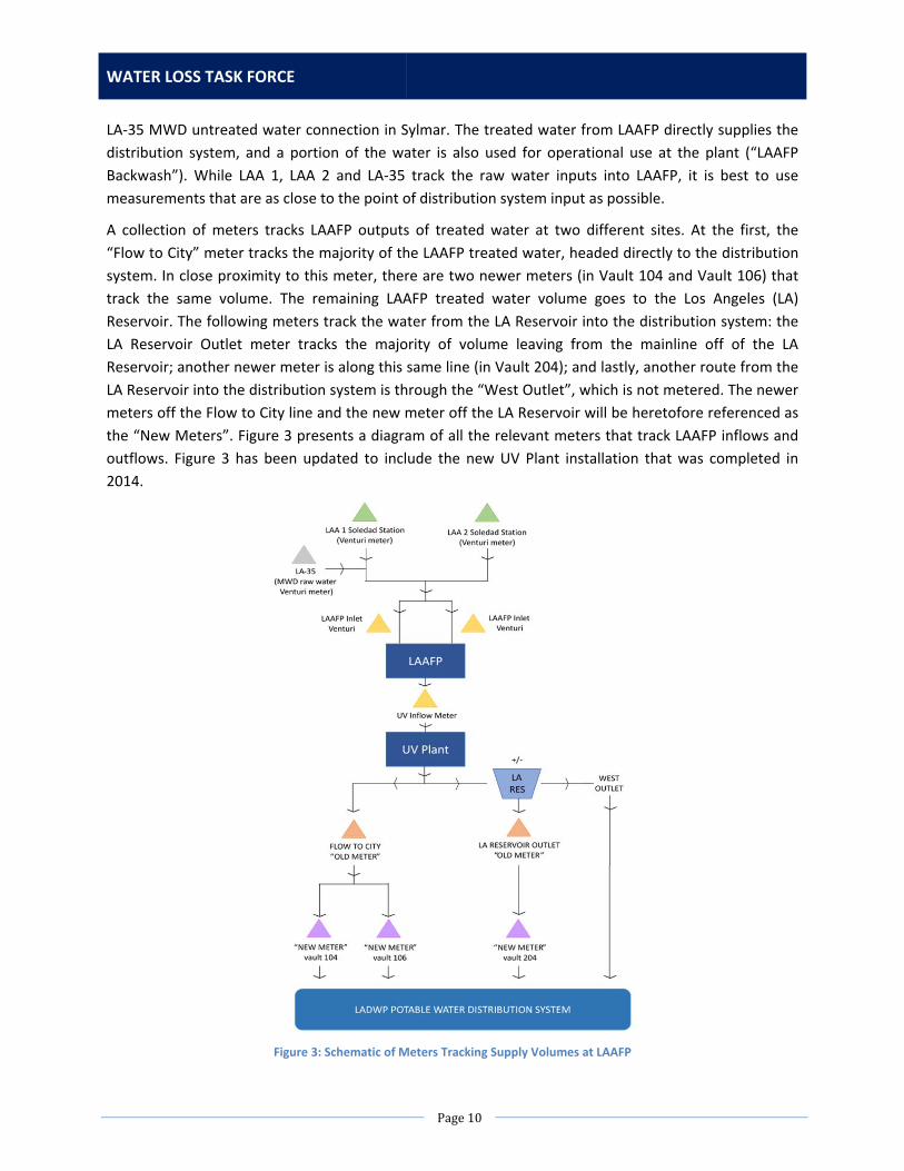
WATER LOSS TASK FORCE
Page10
LA‐35 MWD untreated water connection in Sylmar. The treated water from LAAFP directly supplies the
distribution system, and a portion of the water is also used for operational use at the plant (“LAAFP
Backwash”). While LAA 1, LAA 2 and LA‐35 track the raw water inputs into LAAFP, it is best to use
measurements that are as close to the point of distribution system input as possible.
A collection of meters tracks LAAFP outputs of treated water at two different sites. At the first, the
“Flow to City” meter tracks the majority of the LAAFP treated water, headed directly to the distribution
system. In close proximity to this meter, there are two newer meters (in Vault 104 and Vault 106) that
track the same volume. The remaining LAAFP treated water volume goes to the Los Angeles (LA)
Reservoir. The following meters track the water from the LA Reservoir into the distribution system: the
LA Reservoir Outlet meter tracks the majority of volume leaving from the mainline off of the LA
Reservoir; another newer meter is along this same line (in Vault 204); and lastly, another route from the
LA Reservoir into the distribution system is through the “West Outlet”, which is not metered. The newer
meters off the Flow to City line and the new meter off the LA Reservoir will be heretofore referenced as
the “New Meters”. Figure 3 presents a diagram of all the relevant meters that track LAAFP inflows and
outflows. Figure 3 has been updated to include the new UV Plant installation that was completed in
2014.
Figure 3: Schematic of Meters Tracking Supply Volumes at LAAFP

ACTION PLAN
Page11
Ideally, system input volumes entered into the water balance are measured at the closest point to
system entry. In this case, it would be best to use the three New Meters as they are closest to the point
of input into the distribution system and are newly installed multi‐path ultrasonic flow meters. However,
only going online in January 2012, the New Meters were not in place for the audit period. Moving
forward, LADWP should use the New Meters for all future calculations of System Input Volumes from
LAAFP.
CurrentStatus
Reporting of New LAAFP Effluent Meters
LADWP measures Los Angeles Aqueduct (LAA) water entering the Los Angeles Aqueduct Filtration Plant
(LAAFP) from two meters located in Soledad Canyon. The flows at Soledad are recorded by Water
Operations Division (WOD) Southern Aqueduct Group and reported to DWR and MWD. Water supplied
by MWD at the LA‐35 connection goes through their flow meter and volumes are provided by MWD on
their monthly invoices. The total amount of water entering LAAFP is listed in the monthly Water Supply
Report and is also provided monthly to the LADWP Board of Commissioners.
Water Resources Division (WRD) has been collecting and using LAA flows measured at Soledad in many
ways. Historical LAA metered records dating back to 1916 have been used in studies analyzing trends of
water supply and demand. These are official records reported to DWR and MWD and presented in
publications such as the Urban Water Management Plan.
These historical records were used to establish the baseline gross water use per California Senate Bill x7‐
7 requirements for verifying the required 20% water use reduction by 2020 (20x2020). In order to
maintain a historical consistency, WRD has continued to use the LAA and LA‐35 volumes (representing
the inflows into LAAFP) rather than LAAFP effluent meters to represent supply volumes for almost all
reports. However, the water loss audits reported by LADWP have been using LAAFP effluent meters to
represent supply volumes since FY 2010‐2011.
Meter Testing and Calibration
Volumetric testing and calibration of ultrasonic flow meters requires that they be sent to a facility that
has the capabilities to pass a measurable amount of water through the meters and then compare what
actually passed through the meter with what was measured. Then, the meter is adjusted to match
actual. There are a few facilities in the US that can perform this calibration, most of which are out of
state.
LADWP currently does not perform regular testing of the ultrasonic meters in Vaults 104, 106, and 204
at LAAFP. These are the new effluent meters proposed to be used for future supply volume calculations
and are only checked when an operator reports a specific problem with the meters. Regular testing of
these ultrasonic meters would involve inspection of transducers, transducer cables, and console units;
performance testing of sensors; and signal checking and verification.
WATER LOSS TASK FORCE
Page12
ListofActions
NoAction
Summary of Impact
Complete the annual water loss audit based on the records from three new LAAFP effluent meters. All
other records and reporting remain unchanged and will continue to use the LA Aqueduct Soledad
meters and the LA‐35 meter to represent the flow into the distribution system from LAAFP. Reporting
inconsistencies will continue. Notes explaining the discrepancy need to be included in the annual water
loss audit and documents containing inconsistent records.
Action1:TrackVolumesofWaterSourcesandSystemWaterSupplySeparately
Scope of Work
Water source volumes are required for historical trend analysis and the UWMP. In addition, the new
LAAFP effluent meters do not have historical records to generate a baseline (1996 to 2005) for
determining LA’s compliance to 20% water use reduction in 2020 as required by SBx7‐7 legislation.
System water supply volumes are required for non‐revenue and water loss determination and to
represent the most accurate supply volume to the distribution system.
As the two volumes are required for different purposes, both will tracked and presented in reports such
as the UWMP. Volumes of Water Sources will continue to use Soledad meters and LA‐35 to track LAA
and MWD untreated water. Volumes of System Water Supply will use LAAFP effluent meters to track
amount of water supplied to the water distribution system from the LAAFP.
A System Supply Factor will be calculated to clarify the differences between the two datasets. As stated
from the AWWA Water Balance, the differences between water source volumes and system water
supply volumes include water consumed for treatment operations such as backwashing, basin flushing
and cleaning, etc.
Staffing Needs
An Engineering Associate is needed to investigate data availability, develop procedures, and revise
report templates.
Equipment, Materials, Rentals, and Contract Needs
No additional equipment, materials, rentals, or contracts are needed. Engineering staff may need
coordination from other groups to receive data for compilation.
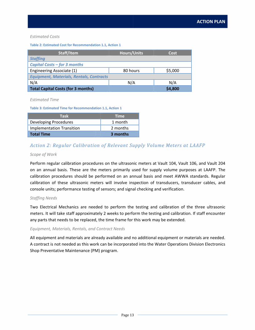
ACTION PLAN
Page13
Estimated Costs
Table 2: Estimated Cost for Recommendation 1.1, Action 1
Staff/Item Hours/Units Cost Staffing
Capital Costs – for 3 months
Engineering Associate (1) 80 hours $5,000
Equipment, Materials, Rentals, Contracts
N/A N/A N/A
Total Capital Costs (for 3 months) $4,800
Estimated Time
Table 3: Estimated Time for Recommendation 1.1, Action 1
Task Time
Developing Procedures 1 month
Implementation Transition 2 months
Total Time 3 months
Action2:RegularCalibrationofRelevantSupplyVolumeMetersatLAAFP
Scope of Work
Perform regular calibration procedures on the ultrasonic meters at Vault 104, Vault 106, and Vault 204
on an annual basis. These are the meters primarily used for supply volume purposes at LAAFP. The
calibration procedures should be performed on an annual basis and meet AWWA standards. Regular
calibration of these ultrasonic meters will involve inspection of transducers, transducer cables, and
console units; performance testing of sensors; and signal checking and verification.
Staffing Needs
Two Electrical Mechanics are needed to perform the testing and calibration of the three ultrasonic
meters. It will take staff approximately 2 weeks to perform the testing and calibration. If staff encounter
any parts that needs to be replaced, the time frame for this work may be extended.
Equipment, Materials, Rentals, and Contract Needs
All equipment and materials are already available and no additional equipment or materials are needed.
A contract is not needed as this work can be incorporated into the Water Operations Division Electronics
Shop Preventative Maintenance (PM) program.

WATER LOSS TASK FORCE
Page14
Estimated Costs
Table 4: Estimated Cost for Recommendation 1.1, Action 2
Staff/Item Hours/Units Cost Staffing
Operations & Maintenance Costs – per year
Instrument Mechanics (2) 108 hours $7,000
Equipment, Materials, Rentals, Contracts
N/A N/A N/A
Total Operations & Maintenance Costs (per year) $7,000
Estimated Time
Table 5: Estimated Time for Recommendation 1.1, Action 2
Task Time
Calibrate Meters 1 month
Total Time 1 month
RecommendedAction
It is recommended to pursue both Actions 1 and 2. Action 1 will clarify data points used in calculations
for sources of supply vs. supply to the water distribution system. Action 1 will also align calculated
values across reports that should represent the same numerical definition, such as non‐revenue water.
Action 2 is required to verify meter functionality of LAAFP meters used for system supply volumes and to
perform regular testing and calibration procedures outlined by the AWWA M36 method. Action 2 will
also improve the data quality and validity score of the “Volume from own sources” entry on the AWWA
water audit software.
Recommendation1.2:LAReservoirWestOutletMeterInstallation
PreviousStudyConclusion
During the FY 2010‐2011 Water Loss Audit and Component Analysis Study, it was determined that there
was some volume of water transferred to the distribution system through another outlet at the LA
Reservoir, the “West Outlet” (see Figure 3). Water Operations records show that the West Outlet was
opened from December 17, 2010 to February 7, 2011. The West Outlet is not metered, so the average
difference between the LAAFP Input Volume and the LAAFP Output Volume was used to estimate the
volume for the West Outlet in December 2010 and January 2011.
The FY 2010‐2011 Water Loss Audit and Component Analysis Study recommended LADWP install an
ultrasonic multi‐point flow meter at the West Outlet to accurately and reliably record the volume
supplied into the distribution network. This would help provide a more accurate system input volume
that is used for calculating water loss.

ACTION PLAN
Page15
CurrentStatus
The Los Angeles Reservoir West Outlet (West Outlet) is typically used when the LA Reservoir Main Outlet
is isolated and for other special operations, such as when the filtration plant is out of service
(unplanned). During these instances, the West Outlet would then be used to supply water to Van
Norman Pump Station #2 and the Rinaldi Trunk Line. There is a manually‐operated valve on the West
Outlet line which is 100% closed and is only operated at the request of Water Control Group.
ListofActions
NoAction
Summary of Impact
The West Outlet is out of service and will not be used except in emergency situations. Therefore the
impact of lack of accurate flow measurement is infrequent.
Action1:CalculateWestOutletFlowusingMassBalance
Scope of Work
This proposed action is to use a mass balance calculation around the Los Angeles Reservoir (LAR). Upon
completion of the UV plant at LAAFP in 2014, there now exists a full set of flow meters providing
measurement of volumes entering and leaving the reservoir except the West Outlet. Measurement of
the level of the reservoir is also available. These values can be used to calculate the volume of water
entering, leaving through the outlet tower, or being stored in the Reservoir with unmetered outflows
passing through the West Outlet.
The LAR inflow cannot be measured directly. The LAR inflow comes from the overflow structure at the
outlet of new LAAFP Ultraviolet (UV) plant. The LAR inflow can be calculated as difference between the
total flow into the UV from the LAAFP and the UV plant outflow to the City. There are redundant meters
on the outflow with the two ultrasonic meters located in Vault 106 and Vault 104 being the most
accurate and the 120” Flow to City magnetic meter being less accurate.
There is an existing sensor to measure the level of the reservoir. This can be used to calculate changes in
water storage in the reservoir.
To measure LAR outflow, there is a flow meter at the Van Norman 2 Chloramination station. In addition,
there is a flow meter at the LAR Outlet Chlorine station that is currently out of service and a new flow
meter will be installed as part of the LAR Outlet UV treatment station.
Using these available process measurements, we can calculate the flow through the West Outlet. The
mass balance calculation is as follows:
West Outlet Flow = Change in Level + (LAAFP Outflow – Vault 104 Flow – Vault 106 Flow) – LAR Outflow
It should be noted that the accuracy of the resulting value is dependent on the accuracy of the primary
measurements.

WATER LOSS TASK FORCE
Page16
Staffing Needs
The different process measurements are currently available on different control systems and they will
need to be brought into the Los Angeles Water System Data Acquisition and Control (LAWSDAC) system
to perform the West Outlet Flow calculation. The LAWSDAC system can also provide reporting and
storage of the information to the historical database. An electrical engineer will be required to make the
necessary programming changes.
Equipment, Materials, Rentals, and Contract Needs
Not applicable.
Estimated Costs
Table 6: Estimated Cost for Recommendation 1.2, Action 1
Staff/Item Hours/Units Cost Staffing
Capital Costs – for 1 month
Electrical Engineering Associate (1) 40 hours $2,000
Equipment, Materials, Rentals, Contracts
N/A N/A N/A
Total Capital Costs (for 1 month) $2,200
Estimated Time
Table 7: Estimated Time for Recommendation 1.2, Action 1
Task Time
System Programming 1 month
Total Time 1 month
Action2:InstallationofFlow MeterontheWestOutlet
Scope of Work
There are two proposed options for installation of a flow meter on the West Outlet line.
The first proposed action is the installation of a flow meter in the valve vault between the two
reservoirs. This is a deep vault with multiple valves and tee to a third pipeline. The structure of the vault
and the location of the valves and tee prevent installation of any flow meter with the required clearance
for sensors. It also obstructs the required straight run of pipe for accurate measurement. Therefore it is
not possible to install a flow meter in the valve vault.
The second proposed option is the construction of a new flow meter vault. The pipeline is buried at an
estimated depth of 80ft. This would require the construction of a very large and very deep vault. The
construction of a vault at this location is not practical because a large dig could compromise the LA
Reservoir.

ACTION PLAN
Page17
Staffing Needs
Not applicable.
Equipment, Materials, Rentals, and Contract Needs
Not applicable.
Estimated Costs
Not applicable.
Estimated Time
Not applicable.
RecommendedAction
If the West Outlet is put into service, it will be necessary to provide measurement of the West Outlet
flow. However, it is not possible to install a flow meter as discussed in Action 2. Therefore, it is
recommended that Action 1, a mass balance calculation using the new UV inflow meter, be
implemented. Action 1 will also improve the data quality and validity score of the “Volume from own
sources” entry on the AWWA water audit software.
Recommendation1.3:WellFieldMeterAccuracyandRegularTesting
PreviousStudyConclusion
LADWP owns and operates wells in 11 different well fields. During FY 2010‐2011, 65 of these wells were
active and registered flow.
At the start of 2011, LADWP initiated a well flow meter testing and calibration program for 60 of the
Department’s San Fernando Valley wells. Approximately 58 of the 60 flow meters have been repaired or
replaced and 44 meters have been tested at three different flow rates to date. Some meters were
repaired after calibration and others replaced with new flow meters. There were some meters that
could not be tested. The high flow rates are representative and typical of the well production values
where the flow meters were installed. The tested accuracies ranged from 98% to 108%. The AWWA
standards on testing and maintaining flow meters (AWWA M6) recommends that 12‐inch propeller
meters (the type and size of most of the well flow meters) should test within 98% and 102%. Many of
the tested flow meters meet this industry standard.
None of the well meters satisfied their manufacturer’s installation requirements. Without sufficient
straight lengths of pipe, it is not guaranteed that a meter performs within its quoted accuracy (even with
mitigating measures such as straightening vanes). Given the installation conditions of the individual well
meters it can be assumed that even newly calibrated well meters will not provide accurate results.
These meters should therefore only be used for general operational purposes and not for accurate
production volumes.

WATER LOSS TASK FORCE
Page18
To improve the accuracy of the well field production volumes the FY2010‐2011 Water Audit and
Component Analysis Study recommended metering the production at a point before or after the
collector basin and not to rely on the results of the individual well meters.
CurrentStatus
Status of Groundwater Meters
Table 8 provides a summary of the types of flow meters and connectivity available for each of the well
fields.
Table 8: Summary of Flow Meters & Connectivity at LADWP Well Fields
Well Field Number of ActiveProduction Wells*
Description of Flow Meters & Connectivity
Lomita Wells 0 This station is not in production and there is no flow meter available on SCADA. There is only one well and it is used as an observation well.
Erwin Wells 2 This station is currently in production but there is no flow meter available on SCADA.
Verdugo Wells 2 This station is currently in production but there is no flow meter available on SCADA.
Whitnall Wells 4 This station is currently in production but there is no flow meter available on SCADA.
99th Street Wells 4 There is a Venturi meter on pump station outlet on LAWSDAC. There is also a propeller meter on well collector line for zinc orthophosphate metering on Distributed Control System (DCS), however a mag‐meter will be installed to replace the propeller meter as part of the new treatment station due in 2016.
Manhattan Wells 2 Insertion mag‐meter on well collector line on Treatment Operations Control Center (TOCC) and a Venturi meter on pump station outlet on LAWSDAC.
Aeration Wells 7 There is an in‐line mag‐meter at the Aeration Tower on TOCC and DCS.
Mission Wells 2 There is a Venturi meter on pump station outlet on DCS and an in‐line mag‐meter on well collector line that will be on TOCC in March 2016. A new treatment station is planned to be in operation around 2018, and will most likely include a new flow meter.
North Hollywood Wells
14 There is an ultrasonic meter on collector line at North Hollywood Station on TOCC.
Pollock Wells 2 There is a Venturi meter on well collector line on DCS.
Rinaldi‐Toluca Wells 15 There is an ultrasonic meter on collector line at North Hollywood Station on TOCC.
Tujunga Wells 12 There is an insertion mag‐meter on well collector line on TOCC and Venturi meter on pump station outlet on LAWSDAC
Total Wells 66 There are currently 66 active wells in production. *As of July 27, 2015
ACTION PLAN
Page19
Magnetic flow meters (mag‐meters) and Ultrasonic meters can be field calibrated. They are very
accurate (approximately 0.5%) if installed as required. When installed near valves, bends, etc., the
accuracy is reduced. Accuracy is also compromised at low flow velocity and partially‐filled pipe. Flow
through Venturi meters is measured using a differential pressure transmitter. These transmitters are
calibrated annually by the instrument shop; the Venturi meter is static and does not require calibration.
Accuracy is similar to the other two meter types with similar caveats.
All of the flow meters noted can be read and logged on one of the three department SCADA systems.
LAWSDAC is the main water SCADA system and will have historical data for many years. DCS is the
SCADA system for the filtration plant and will have data for many years. TOCC is Treatment Operations
Control Center located in the filter plant control Room. This is a relatively new system and will only have
historical data for, at most, a couple of years.
The Water System’s Water Operations and Groundwater Project Management Groups have developed
standardized well construction drawings for new wells that will provide sufficient lengths of straight pipe
that will meet flow meter manufacturer recommendations without the need of straightening vanes.
Existing flow meters without the manufacturer's recommended lengths of straight pipe can be
retrofitted with new straightening vanes that required less straight pipe. The Water System is currently
exploring other types of straightening vanes that greatly reduce the required length of straight pipe (1.5
the pipe diameter upstream and 0 to 1 pipe diameter downstream). Retrofitting existing wells with
other types of straightening vanes can increase meter accuracy to manufacturer's standards. As stated
above, existing well flow meters are being calibrated and new flow meters are also being procured and
installed.
Collector line flow meters have been installed on most well field collector lines. Where collector line
flow meters do not exist, flow measurements are taken at the individual wells and this information is
supplied to Water Control Group to be included in the Upper Los Angeles River Area (ULARA) water
master report. A new replacement flow meter was recently installed on the Tujunga Tank inflow line
and is now operational. New flow meters have been installed on the North Hollywood and Rinaldi
Toluca collector lines but this information is not seen by LAWSDAC. Instead, it is seen on the TOCC
system used by Treatment Operations.
Groundwater Reporting
In June 2015, Water Operations Division Water Control Group began reporting groundwater volumes
from SCADA reads of the collector facility meters for the 8 active well fields where this data is available,
and continued to estimate the remaining active well fields using pump rates and time of operation. Prior
to this, almost all official groundwater reports (with the exception of water loss audits) used meter
reads from the individual well head meters to determine groundwater volume. The decision was made
to switch based on the previous FY 2010‐2011 Water Loss Audit and Component Analysis study findings
that the collector facility meters would provide a more accurate depiction of the groundwater volume
supplied to the water distribution system.
Reports to the ULARA Watermaster continue to require data from manual readings of the individual well
head meters as a representation of groundwater pumped out of the San Fernando Basin. The Urban
WATER LOSS TASK FORCE
Page20
Water Management Plan (UWMP) requires both Watermaster reports and water loss audit
requirements be reported, so both volumes are represented. The Watermaster report is considered a
representation of “sources of supply”, while the water loss audit method is considered a representation
of “system supply volume”, which is sent to the distribution system for use by LADWP customers and
other end‐users.
ListofActions
NoAction
Summary of Impact
By not pursuing any of the actions, the current uncertainty of water quantity coming from some of the
well fields will remain the same. For well‐fields that have flow meters on the well collector line already
installed (such as Manhattan Wells, 99th Street Wells, Aeration Wells, Mission Wells, North Hollywood
Wells, Pollock Wells, Rinaldi‐Toluca Wells, and Tujunga Wells) with signal connectivity to
LAWSDAC/DCS/TOCC, the water flow is sufficiently measured and reported. For well fields that do not
have a flow meter on a collector and access to LAWSDAC/DCS/TOCC (such as Lomita Wells, Verdugo
Wells, Erwin Wells, and Whitnall Wells), the wells flows are currently estimated by pump rate and time
of operation.
Action1:InstallManufacturer’s RecommendedFlow Straighteners
Scope of Work
One of the factors that affect the accuracy of flow measurement is the length of straight pipe that is
available before and after a flow meter. Without sufficient straight pipe length, a meter will not perform
within its rated accuracy. Mitigating measures such as straightening vanes reduce the required length of
straight pipe and can help improve meter accuracy.
Some well fields do not have a flow meter installed on a collector line but rather on the well head. These
well fields include Lomita, Erwin, Verdugo, and Whitnall. In many cases, these flow meters do not have
sufficient straight pipe run upstream and/or downstream of the flow meter that is required for accurate
flow measurement.
All wells already include installations of flow straighteners, but these installations typically require a
straight run of 5 pipe diameters upstream and 10 pipe diameters downstream of the flow meter. To
improve the accuracy of the well head flow meters, it is recommended to install newer technology flow
straighteners at the 8 active wells at Erwin, Verdugo, and Whitnall that cause the flow to become
laminar as it enters and leaves the flow meter and only require one pipe diameter upstream and
downstream of the flow meter. Lomita does not need flow straightener installations because it only has
one inactive well. It is also not recommended at this time to install straighteners at other well fields with
active wells since these other well fields have collector facility meters that can be used to track flows. If
the newer flow straighteners are installed at Erwin, Verdugo, and Whitnall and perform well, it may be
recommended to install the straighteners at other well fields to improve the accuracy of well head
pumping reports submitted to the ULARA Watermaster.

ACTION PLAN
Page21
Staffing Needs
In order to complete this action, the following staff will be needed: one design engineer, one
engineering drafter, and three construction crew staff.
Equipment, Materials, Rentals, and Contract Needs
For each well, a flow straightener and construction equipment will be needed.
Estimated Costs
Table 9: Estimated Cost for Recommendation 1.3, Action 1
Staff/Item Hours/Units Cost Staffing
Capital Costs – for 8 months
Design Engineer (1) 100 hours $6,000
Engineering Drafter (1) 50 hours $2,000
Construction Crew (3) 90 hours $6,000
Equipment, Materials, Rentals, Contracts
Capital Costs
Flow Straightener 1 unit $1,000
Construction Equipment 1 unit $10,000
Total Capital Costs (per well, for 8 months) $26,000
Total Capital Costs (for 8 wells, for 1 year 10 months) $208,000
Estimated Time
Table 10: Estimated Time for Recommendation 1.3, Action 1
Task Time
Planning and Design 1 month
Contract Procurement 6 month
Installation and Testing 1 month
Total Time (per well) 8 month
Total Time (for 8 wells) 1 year 10 months
The total time estimated is 22 months because it is expected that the contract that is procured would be
a one‐time effort and would include the scope of work and funding for all of the flow straighteners
requested.
Action2:InstallationofFlow MetersonWellCollectorLines
Scope of Work
This action recommends the installation of flow meters on existing collector lines where no flow meter
currently exists. The advantages include obtaining sufficiently accurate flow measurements since the
collector line will have adequate straight pipe before and after the flow meter as well as connectivity to
LAWSDAC/TOCC. This eliminates the need for manual tabulation and hence preventing measurement
inaccuracy due to human error.

WATER LOSS TASK FORCE
Page22
Currently, three active well fields do not have collector lines – Erwin, Verdugo, and Whitnall. It is
anticipated that if treatment facilities are planned for in the future at these well fields, a collector line
would be built. At that time, it could be feasible to install a flow meter on the new collector lines.
However, until these treatment facilities are planned and constructed, no opportunity exists to
construct a collector facility meter at Erwin, Verdugo, and Whitnall.
Staffing Needs
In order to complete this action, the following staff will be needed: three design engineers, one
engineering drafter, and seven construction crew.
Equipment, Materials, Rentals, and Contract Needs
For each well field, a flow meter, valves, insulation joints, a maintenance vault and hatch, a
Programmable Logic Controller (PLC) cabinet, other equipment rental, and PLC and LAWSDAC
Connectivity will be needed.
Estimated Costs
Table 11: Estimated Cost for Recommendation 1.3, Action 2
Staff/Item Hours/Units Cost Staffing
Capital Costs – for 11 months
Design Engineers (3) 500 hours $28,000
Engineering Drafter (1) 100 hours $5,000
Construction Crew (7) 300 hours $15,000
Equipment, Materials, Rentals, Contracts
Capital Costs
Flow Meter & Misc. Items (Valves & Insulation Joints etc…)
1 unit $125,000
Maintenance Can and Hatch 1 unit $17,000
PLC Cabinet 1 unit $20,000
Equipment Rental 1 unit $16,000
PLC & LAWSDAC Connectivity 1 unit $150,000
Total Capital Costs (per well field, for 11 months) $376,000
Total Capital Costs (for 3 well fields, for 2 years 9 months) $1,128,000
Estimated Time
Table 12: Estimated Time for Recommendation 1.3, Action 2
Task Time
Planning and Design 4 months
Contract Procurement 6 months
Installation and Testing 1 months
Total Time (per well field) 11 months
Total Time (for 3 well fields) 2 years 9 months

ACTION PLAN
Page23
Action3:CalibrateCollectorFacilityMeters
Scope of Work
This action recommends the calibration of eight flow meters on existing collector lines. The advantages
include ensuring that the flow meters operate properly. Per manufacturer’s recommendation, various
types of flow meters would require different approaches in performing the flow meter calibration. Some
of these tests are provided in Table 13 according to flow meter type.
Table 13: Manufacturer’s Flow Meter Calibration Requirements
1) Primary element flow meters a. Inspect element for wear and proper operations b. Field or factory calibrate differential pressure transmitter to an National Institute of
Standards and Technology (NIST) standard reference
2) Insert mag‐meters a. Inspect insert element and test critical operational values for coil and electrodes b. Field test converter with flow value simulator c. If removable, perform flow calibration
3) In‐line mag‐meters a. Inspect insert element and test critical operational values for coil and electrodes b. Field test converter with flow value simulator
4) Ultrasonic flowmeters a. Inspect transducers, transducer cables, console unit for viable operation b. Confirm viability of each path and performance testing of sensors c. Check operation signal strength values and confirm acceptable to factory standards
Staffing Needs
Design engineers will administer the contract and determine the locations of the meters for the
contractor. A drafter may be needed to create new plans if existing plans are not sufficient to detail the
location and installation conditions of the meters. Operations and construction crew are needed to
accompany the contractor into the vault and open compartments were needed, and potentially assist in
removal and replacement of meters determined to be non‐functional.
Equipment, Materials, Rentals, and Contract Needs
For each flow meter, construction and flow meter testing equipment will be needed.

WATER LOSS TASK FORCE
Page24
Estimated Costs
Table 14: Estimated Cost for Recommendation 1.3, Action 3
Staff/Item Hours/Units Cost Staffing
Operations & Maintenance Costs – per year
Design Engineer (2) 100 hours $6,000
Engineering Drafter (1) 50 hours $3,000
Operations & Construction Crew (3) 60 hours $2,000
Equipment, Materials, Rentals, Contracts
Operations & Maintenance Costs – per year
Flow Meter Testing Contract (per flow meter) 1 unit $2,000
Construction Equipment 1 unit $10,000
Total Operations & Maintenance Costs (per flow meter, per year) $23,000
Total Operations & Maintenance Costs (for 8 flow meters, per year) $184,000
Estimated Time
Table 15: Estimated Time for Recommendation 1.3, Action 3
Task Time
Planning and Design 1 month
Contract Procurement 1 year
Testing 1 month
Total Time (all flow meters) 1 year 2 months
RecommendedAction
It is recommended to pursue Action 2 if collector lines are constructed as part of additional treatment
facilities for the remaining well fields without collector meters at Erwin, Verdugo, and Whitnall. (Lomita
has been taken permanently offline as a production well field, so there is no need to address any meter
inaccuracies at that well field.) A data analysis of groundwater volumes from Erwin, Verdugo, and
Whitnall well fields from years 2013‐2014 showed that these well fields provided around 3% of the total
groundwater volume to the water system. Since this is a relatively small amount, it is recommended to
continue using estimates of flow values based on pump rates and time of operation for three well fields
without collector facility meters until collector lines are built.
It is also recommended to pursue Action 3, meter calibration, for the rest of the active well fields that do
have collector facility meters to meet AWWA calibration requirements to improve water loss audit
validation scores and to catch maintenance issues earlier. Specifically, Action 3 will improve the data
quality and validity score of the “Volume from own sources” entry on the AWWA water audit software.
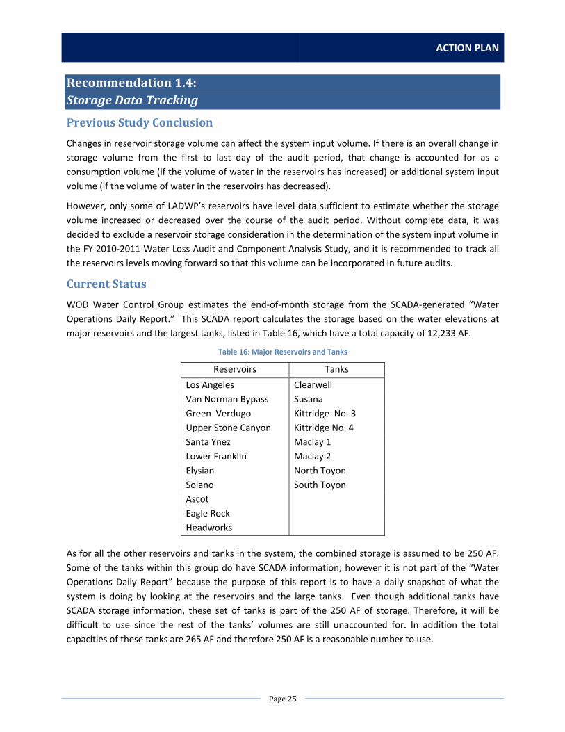
ACTION PLAN
Page25
Recommendation1.4:StorageDataTracking
PreviousStudyConclusion
Changes in reservoir storage volume can affect the system input volume. If there is an overall change in
storage volume from the first to last day of the audit period, that change is accounted for as a
consumption volume (if the volume of water in the reservoirs has increased) or additional system input
volume (if the volume of water in the reservoirs has decreased).
However, only some of LADWP’s reservoirs have level data sufficient to estimate whether the storage
volume increased or decreased over the course of the audit period. Without complete data, it was
decided to exclude a reservoir storage consideration in the determination of the system input volume in
the FY 2010‐2011 Water Loss Audit and Component Analysis Study, and it is recommended to track all
the reservoirs levels moving forward so that this volume can be incorporated in future audits.
CurrentStatus
WOD Water Control Group estimates the end‐of‐month storage from the SCADA‐generated “Water
Operations Daily Report.” This SCADA report calculates the storage based on the water elevations at
major reservoirs and the largest tanks, listed in Table 16, which have a total capacity of 12,233 AF.
Table 16: Major Reservoirs and Tanks
Reservoirs Tanks
Los Angeles Clearwell
Van Norman Bypass Susana
Green Verdugo Kittridge No. 3
Upper Stone Canyon Kittridge No. 4
Santa Ynez Maclay 1
Lower Franklin Maclay 2
Elysian North Toyon
Solano South Toyon
Ascot
Eagle Rock
Headworks
As for all the other reservoirs and tanks in the system, the combined storage is assumed to be 250 AF.
Some of the tanks within this group do have SCADA information; however it is not part of the “Water
Operations Daily Report” because the purpose of this report is to have a daily snapshot of what the
system is doing by looking at the reservoirs and the large tanks. Even though additional tanks have
SCADA storage information, these set of tanks is part of the 250 AF of storage. Therefore, it will be
difficult to use since the rest of the tanks’ volumes are still unaccounted for. In addition the total
capacities of these tanks are 265 AF and therefore 250 AF is a reasonable number to use.

WATER LOSS TASK FORCE
Page26
Since storage for these smaller tanks and reservoirs is always reported as 250 AF, the amount of change
is storage for these facilities is always assumed to be zero. Therefore, this number will not affect the
water balance calculation performed by the AWWA M36 method. Any actual change in storage from
these facilities is almost always negligible when considering the overage storage capacity of LADWP’s
water system.
ListofActions
NoAction
Summary of Impact
Out of 103 reservoirs and tanks that are in‐service, SCADA information is used for 19 of these facilities to
calculate the storage. Even though, the number of facilities is small, it makes up for 98% for the volume.
Therefore, having an estimated volume for the 2% of volume left is within an acceptable low margin of
error.
Action1:AccelerateAdditionofAllReservoirsandTankstoSCADA
Scope of Work
Install additional remote monitoring capabilities for approximately 90 tanks to measure elevations for
the purpose of calculating storage at these facilities. Have custom reports then be built on that SCADA
System that would allow engineering analysis for water audit requirements.
Staffing Needs
A design team of two electrical engineering associates, one drafting tech, two electrical mechanics and
two crafts is needed for the connecting of existing instrumentation and remoting the reads into either
the existing TOCC or LAWSDAC Systems.
Equipment, Materials, Rentals, and Contract Needs
Electrical Cabinets, radios solar power supplies and remote terminal units are needed.

ACTION PLAN
Page27
Estimated Costs
Table 17: Estimated Cost for Recommendation 1.4, Action 1
Staff/Item Hours/Units Cost Staffing
Capital Costs – for 2 months
Electrical Engineering Associates (2) 160 hours $10,000
Drafting Tech (1) 40 hours $2,000
Electrical Mechanics (2) 160 hours $4,000
Crafts (2) 160 hours $5,000
Equipment, Materials, Rentals, Contracts
Capital Costs
Electrical Cabinet, Power Supply and RTU
1 unit $13,000
Solar Power Supply 1 unit $5,000
Radios 2 units $13,000
Concrete Pad/Conduit 1 unit $5,000
Total Capital Costs (per tank, for 2 months) $57,000
Total Capital Costs (for 90 tanks, for 15 years) $5,130,000
Estimated Time
Assuming that the installation is done in‐house and not contracted out, it would take approximately 15
years to have the remaining 90 tanks be added to the SCADA system at a rate of 2 months/tank. The
table below is the breakdown of the time.
Table 18: Estimated Time for Recommendation 1.4, Action 1
Task Time
Planning and Design 1 month
Installation and Testing 1 month
Total Time (per tank) 2 month
Total Time (90 tanks) 15 years
RecommendedAction
The No Action option is recommended since the amount of resources needed, both cost and labor, does
not outweigh the low percentage of error in calculating the small storage volume from reservoirs and
tanks without SCADA information. However, there is currently a program to have visibility at these
reservoirs and tanks by adding them to SCADA for operational purposes. The current rate of progress is
about 1 to 2 tanks a year.
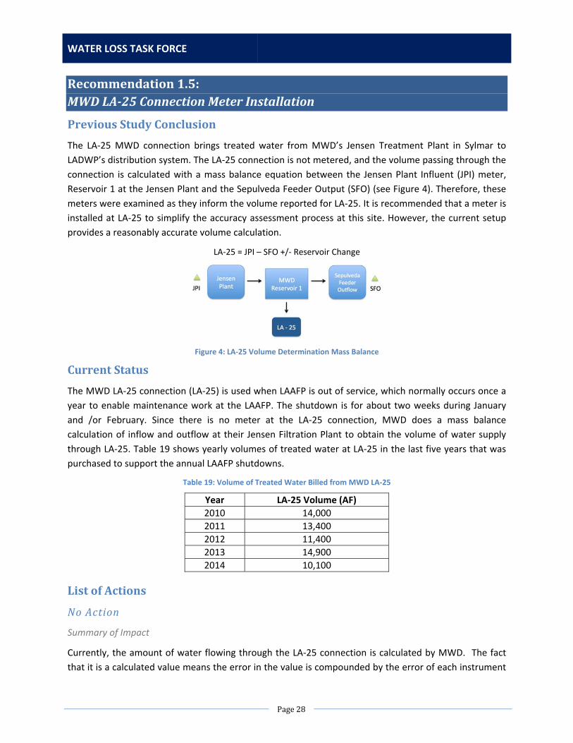
WATER LOSS TASK FORCE
Page28
Recommendation1.5:MWDLA‐25ConnectionMeterInstallation
PreviousStudyConclusion
The LA‐25 MWD connection brings treated water from MWD’s Jensen Treatment Plant in Sylmar to
LADWP’s distribution system. The LA‐25 connection is not metered, and the volume passing through the
connection is calculated with a mass balance equation between the Jensen Plant Influent (JPI) meter,
Reservoir 1 at the Jensen Plant and the Sepulveda Feeder Output (SFO) (see Figure 4). Therefore, these
meters were examined as they inform the volume reported for LA‐25. It is recommended that a meter is
installed at LA‐25 to simplify the accuracy assessment process at this site. However, the current setup
provides a reasonably accurate volume calculation.
LA‐25 = JPI – SFO +/‐ Reservoir Change
Figure 4: LA‐25 Volume Determination Mass Balance
CurrentStatus
The MWD LA‐25 connection (LA‐25) is used when LAAFP is out of service, which normally occurs once a
year to enable maintenance work at the LAAFP. The shutdown is for about two weeks during January
and /or February. Since there is no meter at the LA‐25 connection, MWD does a mass balance
calculation of inflow and outflow at their Jensen Filtration Plant to obtain the volume of water supply
through LA‐25. Table 19 shows yearly volumes of treated water at LA‐25 in the last five years that was
purchased to support the annual LAAFP shutdowns.
Table 19: Volume of Treated Water Billed from MWD LA‐25
Year LA‐25 Volume (AF)
2010 14,000
2011 13,400
2012 11,400
2013 14,900
2014 10,100
ListofActions
NoAction
Summary of Impact
Currently, the amount of water flowing through the LA‐25 connection is calculated by MWD. The fact
that it is a calculated value means the error in the value is compounded by the error of each instrument

ACTION PLAN
Page29
that went into the calculation. Furthermore, LADWP has no control over MWD operations and relies on
MWD to maintain the accuracy of their instrumentation. The result is a value of unknown accuracy.
Action1:InstallanUltrasonicMeterwithInternalMountSensors
Scope of Work
The first option for direct measurement of the LA‐25 flow is the installation of an internally‐mounted
ultrasonic flow meter with a proven accuracy of 0.5%. This flow meter will be installed with internally
mounted sensors and a meter console mounted in instrument cabinet located nearby. A pipe
maintenance manhole will be installed by WDD Trunkline Construction. Installation of the flow meter
sensors is performed by the vendor and LADWP needs to furnish a conduit path to the instrument
cabinet.
Staffing Needs
The installation of the flow meter will require staffing to plan, design, manage and install the flow meter
and manhole with precast vault. Engineering staff will be required to design, specify and purchase the
materials and manage their installation. The actual flow meter installation will be performed by the
vendor and is included in the purchase price. WDD Trunkline Construction crews will be required to
install the manhole, vault and buried conduit. We will require instrument mechanics to program the PLC
and commission the flow meter.
Equipment, Materials, Rentals, and Contract Needs
Materials are limited to the flow meter and construction materials to install the buried conduits. An
asphalt paving contractor will be required to repair road surfaces.
Estimated Costs
Table 20: Estimated Cost for Recommendation 1.5, Action 1
Staff/Item Hours/Units Cost Staffing
Capital Costs – for 1 year
Project Management 160 hours $12,000
Mechanical Engineering 800 hours $56,000
Electrical Engineering 160 hours $11,000
Repair & Construction (R&C) 800 hours $53,000
Trunkline Construction 2,000 hours $116,000
Operations 200 hours $15,000
Equipment, Materials, Rentals, Contracts
Capital Costs
Ultrasonic Flow Meter 1 unit $100,000
Precast Manhole 1 unit $10,000
Trenching & Paving Contract 1 unit $10,000
Total Capital Costs (for 1 year) $383,000

WATER LOSS TASK FORCE
Page30
Estimated Time
Table 21: Estimated Time for Recommendation 1.5, Action 1
Task Time
Planning and Design 4 months
Contract Procurement 6 months
Installation and Testing 2 months
Total Time 1 year
Action2:InstallanUltrasonicMeterwithThru‐MountSensors
Scope of Work
The second option for direct measurement of the LA‐25 flow is the construction of flow meter vault and
the installation of “thru‐mount” ultrasonic flow meter. This type flow meter will provide accuracy of
0.5%.
A new vault would be constructed upstream of the LA‐25 valve vault in an optimal location for flow
meter accuracy. The vault would be large enough to permit the access to tapping holes and installing
sensors around circumference of the pipe. The vault would require electrical equipment such as lighting,
a sump pump, and a blower. The flow meter console will be mounted in instrument cabinet located
nearby with buried conduit installed between the vault and cabinet. All work would be performed the
department.
Staffing Needs
The installation of the flow meter will require staffing to plan, manage, design, construct, and
commission the custom vault and flow meter. Civil and structural engineering staff will be required to
research, design, and supervise construction the vault. Mechanical and electrical engineering staff will
be required to design, specify, and purchase the flow meter and electrical equipment. Department
construction crews would be required to construct the vault and install the flow meter.
Equipment, Materials, Rentals, and Contract Needs
Materials required include the flow meter, construction materials for the vault and electrical equipment.
Rentals will be required for construction equipment and shoring.
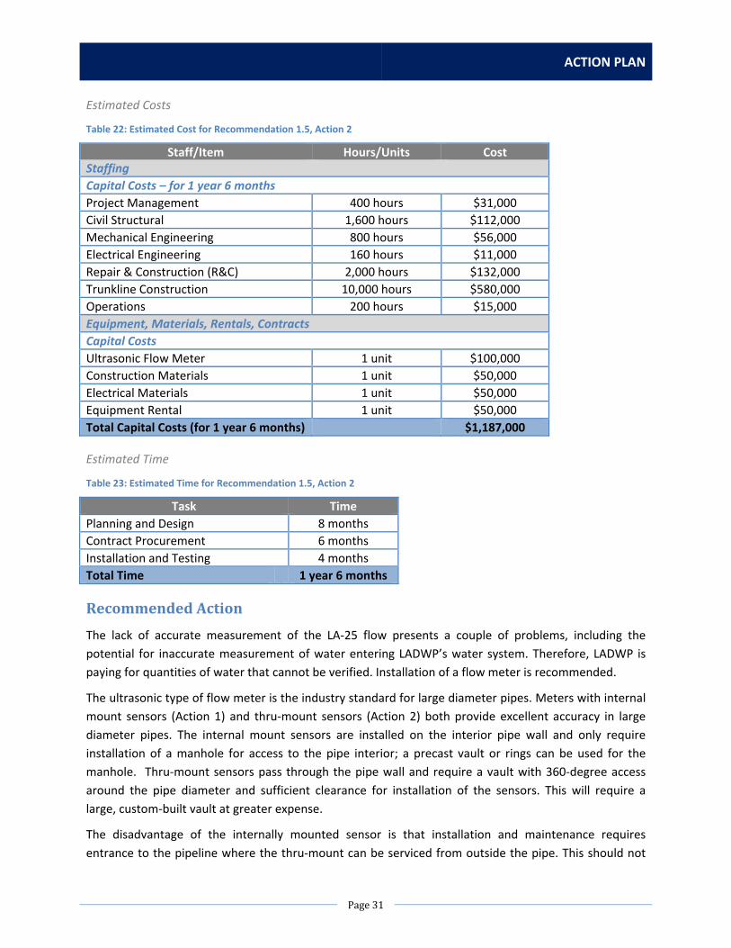
ACTION PLAN
Page31
Estimated Costs
Table 22: Estimated Cost for Recommendation 1.5, Action 2
Staff/Item Hours/Units Cost Staffing
Capital Costs – for 1 year 6 months
Project Management 400 hours $31,000
Civil Structural 1,600 hours $112,000
Mechanical Engineering 800 hours $56,000
Electrical Engineering 160 hours $11,000
Repair & Construction (R&C) 2,000 hours $132,000
Trunkline Construction 10,000 hours $580,000
Operations 200 hours $15,000
Equipment, Materials, Rentals, Contracts
Capital Costs
Ultrasonic Flow Meter 1 unit $100,000
Construction Materials 1 unit $50,000
Electrical Materials 1 unit $50,000
Equipment Rental 1 unit $50,000
Total Capital Costs (for 1 year 6 months) $1,187,000
Estimated Time
Table 23: Estimated Time for Recommendation 1.5, Action 2
Task Time
Planning and Design 8 months
Contract Procurement 6 months
Installation and Testing 4 months
Total Time 1 year 6 months
RecommendedAction
The lack of accurate measurement of the LA‐25 flow presents a couple of problems, including the
potential for inaccurate measurement of water entering LADWP’s water system. Therefore, LADWP is
paying for quantities of water that cannot be verified. Installation of a flow meter is recommended.
The ultrasonic type of flow meter is the industry standard for large diameter pipes. Meters with internal
mount sensors (Action 1) and thru‐mount sensors (Action 2) both provide excellent accuracy in large
diameter pipes. The internal mount sensors are installed on the interior pipe wall and only require
installation of a manhole for access to the pipe interior; a precast vault or rings can be used for the
manhole. Thru‐mount sensors pass through the pipe wall and require a vault with 360‐degree access
around the pipe diameter and sufficient clearance for installation of the sensors. This will require a
large, custom‐built vault at greater expense.
The disadvantage of the internally mounted sensor is that installation and maintenance requires
entrance to the pipeline where the thru‐mount can be serviced from outside the pipe. This should not
WATER LOSS TASK FORCE
Page32
be a major problem since this line is not normally in service. Another potential issue of the internally
mounted sensor is that this type of meter installation has not been used by the Water System; however,
the Power System has used this meter with good results on hydro‐generation systems.
Action 1 is recommended over Action 2 and the “No Action” option. A new flow meter will provide
accurate flow measurement. It can be installed quickly and with lower cost and less resources than the
second action. Action 1 will also improve the data quality and validity score of the “Water imported”
entry on the AWWA water audit software.

ACTION PLAN
Page33
Section2:DatabaseManagement
Database Management refers to the procedures for updating and maintaining system databases, as well
as providing a reasonable level of data accuracy and ease of data retrieval. Some of the major databases
that house data relevant to the water balance calculation and water loss studies include (but are not
limited to):
Customer Information System (CIS) – the old billing system
Customer Care & Billing (CCB) – the new billing system
Work Management Information System (WMIS) – tracks water meter and service data
LAWSDAC – Supervisory Control and Data Acquisition (SCADA) system for water operations
Wave Server – Distributed Control System (DCS) for treatment plant specific operations
Leak Information Database – GIS‐based system that tracks mainline leak reports
Construction Productivity System (CPS) – tracks work orders for projects, including service leaks
Errors in data collection and storage can adversely affect calculations in multiple areas of the water
balance. Difficulties in data retrieval due to overly complicated databases can also delay analyses of
water loss in the system and hinder the ability to perform the water audit by mandated regulatory
deadlines.
Recommendation2.1:WaterControlSystemsDatabaseConsolidation
PreviousStudyConclusion
LADWP should consider consolidating its Water Control Systems databases. For the LAAFP volume
analysis alone, data from three separate Water Control Systems was required. This included the Owens
Valley SCADA system, which provided the data for the LAA pipelines; Los Angeles Water System Data
Acquisition and Control (LAWSDAC), which provided most of the system input volume data; and the
LAAFP Distributed Control System (DCS), which provided the data for the “New Meters” on the effluent
side at the LAAFP. With different data extraction procedures and permissions for each SCADA system
and the DCS, the data collection process for System Input Volume determination becomes quite
cumbersome and introduces a greater probability for error in data collection and analysis.
CurrentStatus
The Water Control Systems used in the LADWP Water System are presented in Table 24.
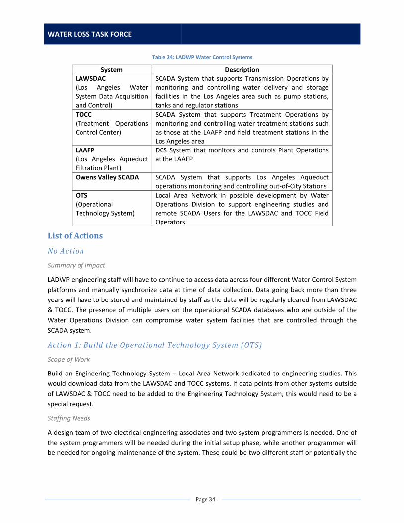
WATER LOSS TASK FORCE
Page34
Table 24: LADWP Water Control Systems
System Description
LAWSDAC (Los Angeles Water System Data Acquisition and Control)
SCADA System that supports Transmission Operations by monitoring and controlling water delivery and storage facilities in the Los Angeles area such as pump stations, tanks and regulator stations
TOCC (Treatment Operations Control Center)
SCADA System that supports Treatment Operations by monitoring and controlling water treatment stations such as those at the LAAFP and field treatment stations in the Los Angeles area
LAAFP (Los Angeles Aqueduct Filtration Plant)
DCS System that monitors and controls Plant Operations at the LAAFP
Owens Valley SCADA SCADA System that supports Los Angeles Aqueduct operations monitoring and controlling out‐of‐City Stations
OTS (Operational Technology System)
Local Area Network in possible development by Water Operations Division to support engineering studies and remote SCADA Users for the LAWSDAC and TOCC Field Operators
ListofActions
NoAction
Summary of Impact
LADWP engineering staff will have to continue to access data across four different Water Control System
platforms and manually synchronize data at time of data collection. Data going back more than three
years will have to be stored and maintained by staff as the data will be regularly cleared from LAWSDAC
& TOCC. The presence of multiple users on the operational SCADA databases who are outside of the
Water Operations Division can compromise water system facilities that are controlled through the
SCADA system.
Action1:BuildtheOperationalTechnologySystem (OTS)
Scope of Work
Build an Engineering Technology System – Local Area Network dedicated to engineering studies. This
would download data from the LAWSDAC and TOCC systems. If data points from other systems outside
of LAWSDAC & TOCC need to be added to the Engineering Technology System, this would need to be a
special request.
Staffing Needs
A design team of two electrical engineering associates and two system programmers is needed. One of
the system programmers will be needed during the initial setup phase, while another programmer will
be needed for ongoing maintenance of the system. These could be two different staff or potentially the
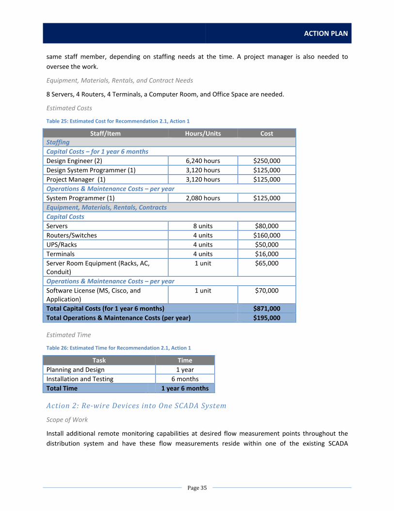
ACTION PLAN
Page35
same staff member, depending on staffing needs at the time. A project manager is also needed to
oversee the work.
Equipment, Materials, Rentals, and Contract Needs
8 Servers, 4 Routers, 4 Terminals, a Computer Room, and Office Space are needed.
Estimated Costs
Table 25: Estimated Cost for Recommendation 2.1, Action 1
Staff/Item Hours/Units Cost Staffing
Capital Costs – for 1 year 6 months
Design Engineer (2) 6,240 hours $250,000
Design System Programmer (1) 3,120 hours $125,000
Project Manager (1) 3,120 hours $125,000
Operations & Maintenance Costs – per year
System Programmer (1) 2,080 hours $125,000
Equipment, Materials, Rentals, Contracts
Capital Costs
Servers 8 units $80,000
Routers/Switches 4 units $160,000
UPS/Racks 4 units $50,000
Terminals 4 units $16,000
Server Room Equipment (Racks, AC, Conduit)
1 unit $65,000
Operations & Maintenance Costs – per year
Software License (MS, Cisco, and Application)
1 unit $70,000
Total Capital Costs (for 1 year 6 months) $871,000
Total Operations & Maintenance Costs (per year) $195,000
Estimated Time
Table 26: Estimated Time for Recommendation 2.1, Action 1
Task Time
Planning and Design 1 year
Installation and Testing 6 months
Total Time 1 year 6 months
Action2:Re‐wireDevicesintoOneSCADA System
Scope of Work
Install additional remote monitoring capabilities at desired flow measurement points throughout the
distribution system and have these flow measurements reside within one of the existing SCADA

WATER LOSS TASK FORCE
Page36
Systems. Each site has a capacity of eight status points and four analog points. Have custom reports
then be built on that SCADA System that would allow engineering analysis for water audit requirements.
Staffing Needs
A design team of two electrical engineering associates, one drafting tech, two electrical mechanics and
two crafts is needed for the connecting of existing instrumentation and remoting the reads to the
preferred SCADA system.
Equipment, Materials, Rentals, and Contract Needs
Electrical Cabinets, Radio Solar Power Supplies and Remote Terminal Units are needed.
Estimated Costs
Table 27: Estimated Cost for Recommendation 2.1, Action 2
Staff/Item Hours/Units Cost Staffing
Capital Costs – for 2 months
Electrical Engineering Associates (2) 160 hours $10,000
Drafting Tech (1) 40 hours $2,000
Electrical Mechanics (2) 160 hours $4,000
Crafts (2) 160 hours $5,000
Equipment, Materials, Rentals, Contracts
Capital Costs
Electrical Cabinet, Power Supply and RTU
1 unit $13,000
Solar Power Supply 1 unit $5,000
Radios 2 units $13,000
Concrete Pad/Conduit 1 unit $5,000
Total Capital Costs (per site, for 2 months) $57,000
Currently only one site has been identified as a priority for re‐wiring, but more sites may be identified in
the future based on engineering data needs.
Estimated Time
Table 28: Estimated Time for Recommendation 2.1, Action 2
Task Time
Planning and Design 1 month
Installation and Testing 1 month
Total Time (per site) 2 months
RecommendedAction
WOD Water Technology & Control Systems (WTCS) Group is currently evaluating the feasibility of
creating the OTS as outlined in Action 1. It is recommended to go with the No Action option until WTCS
Group can verify the feasibility of pursuing Action 1. During the time Action 1 is being evaluated, LADWP

ACTION PLAN
Page37
engineering staff can provide any data points that are of interest but not currently on LAWSDAC or TOCC
to WTCS Group for addition to one of the two systems.
Recommendation2.2:RecycledWaterandTreatmentProcessWaterTracking
PreviousStudyConclusion
For the purposes of creating a consistent and complete water balance, the consumption volume
determination must correspond with the system input volume: only consumption that draws from the
water supplied (as calculated in the system input volume calculation) qualifies as Billed Metered
Authorized Consumption (BMAC) in the water balance. As such only potable water that is consumed
after the points of system input volume metering is included in BMAC. Figure 5 shows the BMAC as a
part of the water balance.
Water Supplied
Authorized Consumption
Billed Authorized Consumption
Billed Metered Consumption Revenue Water
Billed Unmetered Consumption
Unbilled Authorized Consumption
Unbilled Metered Consumption
Non‐Revenue Water
Unbilled Unmetered Consumption
Water Losses
Apparent Losses
Unauthorized Consumption
Customer Meter Inaccuracies
Data Handling Errors
Real Losses
Figure 5: Billed Metered Authorized Consumption Identified in the Water Balance (Not to Scale)
The first group of exclusions from the BMAC volume includes the accounts that receive recycled water.
This audit is limited to the potable water system, so any recycled water accounts tracked in the
Customer Information System (CIS) must be excluded. In CIS, the rate code “44” highlights records that
refer to recycled water. In the first review of the CIS data, all billing records with rate code “44” were
removed.
Upon further investigation, it became clear that a significant number of accounts receive recycled water
without the rate code “44” distinction on their billing records. The LADWP Water Recycling and Planning
Group provided their documentation of these accounts’ information, which was then cross‐referenced
with CIS. Through this effort, beyond the rate code “44” accounts, an additional 544.95 MG or 1,672.39
AF was excluded from the final BMAC volume determination. In future water audits, it will be important
to exclude all accounts that receive recycled water.
The second group of exclusions from the BMAC volume includes treatment process water. All
consumption included in the BMAC volume determination must be accounted for in the system input
volume. This is not the case for a small number of accounts that use potable water before the points of
measurement for the system input volume. A particular account of note is Meter Number 96101258
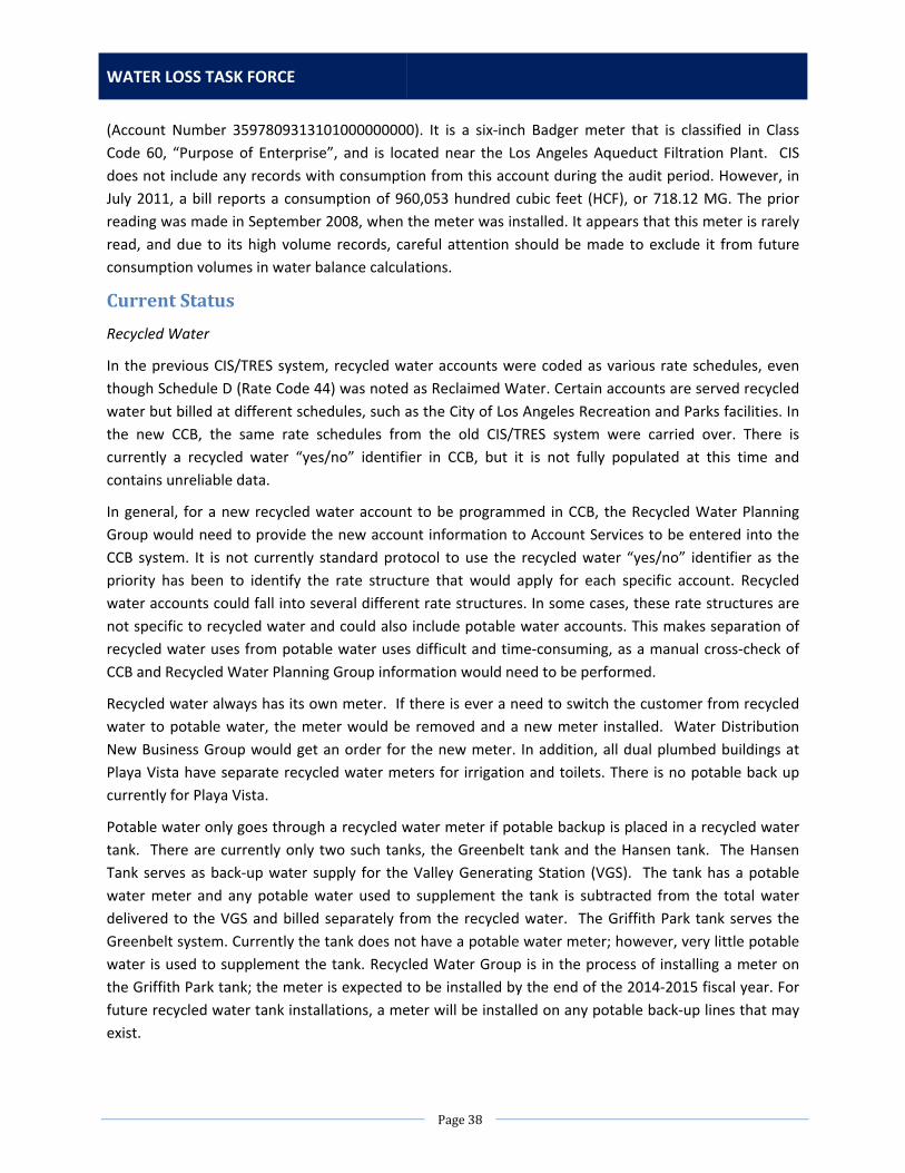
WATER LOSS TASK FORCE
Page38
(Account Number 3597809313101000000000). It is a six‐inch Badger meter that is classified in Class
Code 60, “Purpose of Enterprise”, and is located near the Los Angeles Aqueduct Filtration Plant. CIS
does not include any records with consumption from this account during the audit period. However, in
July 2011, a bill reports a consumption of 960,053 hundred cubic feet (HCF), or 718.12 MG. The prior
reading was made in September 2008, when the meter was installed. It appears that this meter is rarely
read, and due to its high volume records, careful attention should be made to exclude it from future
consumption volumes in water balance calculations.
CurrentStatus
Recycled Water
In the previous CIS/TRES system, recycled water accounts were coded as various rate schedules, even
though Schedule D (Rate Code 44) was noted as Reclaimed Water. Certain accounts are served recycled
water but billed at different schedules, such as the City of Los Angeles Recreation and Parks facilities. In
the new CCB, the same rate schedules from the old CIS/TRES system were carried over. There is
currently a recycled water “yes/no” identifier in CCB, but it is not fully populated at this time and
contains unreliable data.
In general, for a new recycled water account to be programmed in CCB, the Recycled Water Planning
Group would need to provide the new account information to Account Services to be entered into the
CCB system. It is not currently standard protocol to use the recycled water “yes/no” identifier as the
priority has been to identify the rate structure that would apply for each specific account. Recycled
water accounts could fall into several different rate structures. In some cases, these rate structures are
not specific to recycled water and could also include potable water accounts. This makes separation of
recycled water uses from potable water uses difficult and time‐consuming, as a manual cross‐check of
CCB and Recycled Water Planning Group information would need to be performed.
Recycled water always has its own meter. If there is ever a need to switch the customer from recycled
water to potable water, the meter would be removed and a new meter installed. Water Distribution
New Business Group would get an order for the new meter. In addition, all dual plumbed buildings at
Playa Vista have separate recycled water meters for irrigation and toilets. There is no potable back up
currently for Playa Vista.
Potable water only goes through a recycled water meter if potable backup is placed in a recycled water
tank. There are currently only two such tanks, the Greenbelt tank and the Hansen tank. The Hansen
Tank serves as back‐up water supply for the Valley Generating Station (VGS). The tank has a potable
water meter and any potable water used to supplement the tank is subtracted from the total water
delivered to the VGS and billed separately from the recycled water. The Griffith Park tank serves the
Greenbelt system. Currently the tank does not have a potable water meter; however, very little potable
water is used to supplement the tank. Recycled Water Group is in the process of installing a meter on
the Griffith Park tank; the meter is expected to be installed by the end of the 2014‐2015 fiscal year. For
future recycled water tank installations, a meter will be installed on any potable back‐up lines that may
exist.

ACTION PLAN
Page39
Treatment Process Water
There are some meters located at or near the LAAFP that appear to measure flows related to treatment
processes. However, these meters are read and the readings are entered into the billing system. When
this happens, water that would typically be classified as a supply volume is included in the consumption
volume total.
In order to mitigate this potential double‐counting effect, LADWP staff are currently investigating the
installation conditions and intended purpose of these meters, as well as analyzing the best way to track
these flows.
ListofActions
NoAction
Summary of Impact
Information in CCB and Recycled Water Planning Group databases would continue to be manually cross‐
checked upon request to determine the total recycled water usage in LADWP’s customer base, which is
time consuming for staff.
Action1:AddaRecycledWaterIdentifierintheBillingSystem
Scope of Work
Information Technology Services Division (ITS) would perform an initial check of the current data set in
CCB to check if the recycled water “yes/no” identifier is already filled out correctly. Recycled Water
Planning Group would need to provide to ITS the current full list of recycled water accounts in a specific
format to be identified by ITS. Recycled Water Planning Group would also need to coordinate with
Account Services to provide information on any new recycled water accounts in the future. Account
Services would then be responsible for populating the recycled water “yes/no” identifier. With these
new procedures, recycled water usage could be easily extracted from CCB by filtering data through the
“yes/no” identifier.
In the future, it may be worthwhile to investigate the possibility of adding a new attribute in CCB with a
two‐digit code identifier for different types of recycled water accounts (tertiary treated vs. advanced
reverse osmosis treated, for example), but this has not been included in this action at this time.
Staffing Needs
The following staff are needed to complete this work: one Senior Systems Analyst, one Programmer
Analyst, one Database Architect, and one Senior Utility Services Specialist.
Equipment, Materials, Rentals, and Contract Needs
No additional equipment, materials, rentals, or contracts are needed to perform this work.
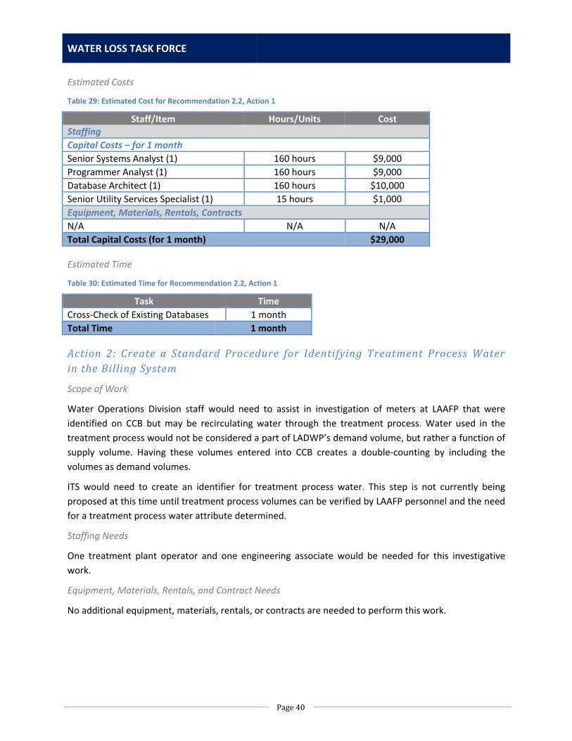
WATER LOSS TASK FORCE
Page40
Estimated Costs
Table 29: Estimated Cost for Recommendation 2.2, Action 1
Staff/Item Hours/Units Cost Staffing
Capital Costs – for 1 month
Senior Systems Analyst (1) 160 hours $9,000
Programmer Analyst (1) 160 hours $9,000
Database Architect (1) 160 hours $10,000
Senior Utility Services Specialist (1) 15 hours $1,000
Equipment, Materials, Rentals, Contracts
N/A N/A N/A
Total Capital Costs (for 1 month) $29,000
Estimated Time
Table 30: Estimated Time for Recommendation 2.2, Action 1
Task Time
Cross‐Check of Existing Databases 1 month
Total Time 1 month
Action 2: Create a Standard Procedure for Identifying Treatment ProcessWaterintheBillingSystem
Scope of Work
Water Operations Division staff would need to assist in investigation of meters at LAAFP that were
identified on CCB but may be recirculating water through the treatment process. Water used in the
treatment process would not be considered a part of LADWP’s demand volume, but rather a function of
supply volume. Having these volumes entered into CCB creates a double‐counting by including the
volumes as demand volumes.
ITS would need to create an identifier for treatment process water. This step is not currently being
proposed at this time until treatment process volumes can be verified by LAAFP personnel and the need
for a treatment process water attribute determined.
Staffing Needs
One treatment plant operator and one engineering associate would be needed for this investigative
work.
Equipment, Materials, Rentals, and Contract Needs
No additional equipment, materials, rentals, or contracts are needed to perform this work.

ACTION PLAN
Page41
Estimated Costs
Table 31: Estimated Cost for Recommendation 2.2, Action 2
Staff/Item Hours/Units Cost Staffing
Capital Costs – for 1 month
Filtration Plant Operator (1) 80 hours $4,000
Engineering Associate (1) 80 hours $4,000
Equipment, Materials, Rentals, Contracts
N/A N/A N/A
Total Capital Costs (for 1 month) $8,000
Estimated Time
Table 32: Estimated Time for Recommendation 2.2, Action 2
Task Time
Investigation of LAAFP Meters Identified in CCB
1 month
Total Time 1 month
RecommendedAction
It is recommended to pursue both Actions 1 and 2 in order to verify recycled water uses and treatment
process water uses in LADWP’s system. Actions 1 and 2 will also improve the data quality and validity
score of the “Billed metered” entry on the AWWA water audit software.
Recommendation2.3:CISandWMISInconsistencies
PreviousStudyConclusion
In order to organize the billing and meter data to perform a consumption analysis, an attempt was made
to merge the Customer Information System (CIS) and Work Management Information System (WMIS)
databases. The goal was to link each account from CIS to the WMIS data in order to populate each
account with both the consumption data (from CIS) and the most current meter information (from
WMIS).
After some initial data analysis and review, it was determined that linking the databases was not
possible. The service code was first used as a possible linking identifier between the two databases.
However, CIS has 364,979 unique service codes and WMIS provides 691,297 unique service codes.
Another attempt was made to link the databases based on the meter number provided. Here, it was also
determined that there was insufficient overlap between the two databases: there are 721,997 unique
meters in CIS and only 700,433 unique meters numbers in WMIS. Without the consistency in account
information necessary to merge the two databases, it was decided to use the information only provided
in CIS for the complete billing data analysis.
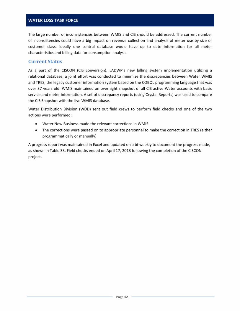
WATER LOSS TASK FORCE
Page42
The large number of inconsistencies between WMIS and CIS should be addressed. The current number
of inconsistencies could have a big impact on revenue collection and analysis of meter use by size or
customer class. Ideally one central database would have up to date information for all meter
characteristics and billing data for consumption analysis.
CurrentStatus
As a part of the CISCON (CIS conversion), LADWP’s new billing system implementation utilizing a
relational database, a joint effort was conducted to minimize the discrepancies between Water WMIS
and TRES, the legacy customer information system based on the COBOL programming language that was
over 37 years old. WMIS maintained an overnight snapshot of all CIS active Water accounts with basic
service and meter information. A set of discrepancy reports (using Crystal Reports) was used to compare
the CIS Snapshot with the live WMIS database.
Water Distribution Division (WDD) sent out field crews to perform field checks and one of the two
actions were performed:
Water New Business made the relevant corrections in WMIS
The corrections were passed on to appropriate personnel to make the correction in TRES (either
programmatically or manually)
A progress report was maintained in Excel and updated on a bi‐weekly to document the progress made,
as shown in Table 33. Field checks ended on April 17, 2013 following the completion of the CISCON
project.

ACTION PLAN
Page43
Table 33: Number of Cross‐Database Discrepancies Checked During CISCON
DATE 1/2/2013 2/19/2013 3/5/2013 3/20/2013 3/27/2013 4/17/2013
WMIS‐CIS SERVICE NUMBER DISCREPANCIES
# Records # Records # Records # Records # Records # Records
METER AT ANOTHER SERVICE NUMBER
670 572 452 393 398 377
ADDRESS AT ANOTHER SERVICE NUMBER
666 669 563 285 287 273
UNKNOWN 1,761 1,958 1,521 767 678 567
SUBTOTAL 3,097 3,199 2,536 1,445 1,363 1,217
WMIS‐CIS METER NUMBER DISCREPANCIES
# Records # Records # Records # Records # Records # Records
CIS HAS OLDER METER 1,277 982 615 639 635 687
CIS HAS OLDER METER / ALSO AT ANOTHER SERVICE
272 268 263 260 261 259
METER AT ANOTHER SERVICE 1,907 1,730 1,737 1,808 1,804 1,787
TRANSPOSED 433 434 435 435 435 434
TYPO 968 966 970 964 964 967
TYPO / ALSO AT ANOTHER SERVICE
905 917 905 912 912 903
UNKNOWN 6,011 6,027 6,014 7,093 2,421 2,101
SUBTOTAL 11,773 11,324 10,939 12,111 7,432 7,138
WMIS‐CIS ERT NUMBER DISCREPANCIES
# Records # Records # Records # Records # Records # Records
DIFFERENT ERT NUMBER AT SAME METER NUMBER
UNK 4,665 4,046 5,896 5,989 5,931
DIFFERENT METER NUMBER WITH SAME ERT NUMBER
UNK 2,358 1,741 1,626 1,667 1,423
DUPLICATE ERT NUMBER IN TRES
UNK 634 365 365 365 145
DUPLICATE ERT NUMBER IN WMIS
UNK 214 200 81 247 240
Bad Length ERT# (in WMIS) 220
Bad Length ERT# (in TRES) 644
SUBTOTAL 0 7,871 6,352 7,968 8,268 8,603
GIS DISCREPANCIES # Records # Records # Records # Records # Records # Records
DUPLICATE SERVICES IN GIS UNK 2,185 1,738 1,198
SERVICES NOT CONNECTED TO SUPPLY IN GIS
UNK 12,041 12,041 12,041
SUBTOTAL 0 14,226 13,779 13,239 0
TOTAL ALL CATEGORIES 14,870 36,620 33,606 34,763 17,063 16,958

WATER LOSS TASK FORCE
Page44
ListofActions
NoAction
Summary of Impact
By taking no action, the potential for lost revenues (meters found in the field not installed in CCB)
increases as well as not meeting the customer’s expectations of a timely and accurate billing.
Action1:AddresstheRemainingDuplicate BadgeNumbers
Scope of Work
Customer Service Division (CSD) Account Services Unit (ASU) will continue with the effort of identifying
and correcting duplicate water badge numbers by correcting possible clerical errors. Badges that require
field checks will initially be done by meter reading at an effort to verify correct badge number and
capture current meter read. Field investigation will provide support when additional information is
needed and billing instructions required. In addition, ASU will work with Water Distribution Division
(WDD) to correct duplicate water check detectors, Fire Services and ERTs. Once the field information is
provided to ASU from both Field Investigation and WDD, corrections will be done to the billing system to
ensure accurate billing. There are currently a total of 451 duplicate water badge numbers in CCB. This
includes 5 detector checks.
Staffing Needs
It is estimated that one customer service representative and one field investigator will be needed to be
able to correct the information in the field and in CCB in a period of four months.
Equipment, Materials, Rentals, and Contract Needs
No new equipment is needed. All equipment and materials needed are already in use by the
Department.
Estimated Costs
Table 34: Estimated Cost for Recommendation 2.3, Action 1
Staff/Item Hours/Units Cost Staffing
Capital Costs – for 4 months
Customer Service Representatives (1) 320 hours $12,000
Field Investigator (1) 320 hours $14,000
Equipment, Materials, Rentals, Contracts
N/A N/A N/A
Total Capital Costs (for 4 months) $26,000
Note that the staffing costs shown are estimated and dependent on resources available. CSD is
committed to ensuring this issue is addressed and will allocate staff to complete this work as needed.

ACTION PLAN
Page45
Estimated Time
Table 35: Estimated Time for Recommendation 2.3, Action 1
Task Time
CSD Investigation 3 months
Detector Check Verification 1 month
Total Time 4 months
RecommendedAction
It is recommended to pursue Action 1, which is to work down the duplicate badge numbers in CCB.
Action 1 will also improve procedures and accuracy of meter testing and consumption profiling activities
outlined in Section 3.
Recommendation2.4:LeakDatabaseConsolidationandAccuracy
PreviousStudyConclusion
As one of the main data collection efforts for the component analysis of real losses, records for all
infrastructure failures during the audit period were requested. Failures on service connections, mains,
and mains appurtenances are required for a complete component analysis of real losses. This proved to
be an especially effort intensive task given LADWP’s current tracking system for Reported Leaks.
To capture all the failures in the system for the audit period, three different groups of leak events – each
differentiated by separate data compilation processes – were considered. Figure 6 shows the location of
each of the different leak types in relation to the main and the curb. The following sections describe
how the reported leak data was compiled for each type of leak.
Figure 6: Diagram Showing Classification of Leak Types A, B, & C
The first data collection effort involves main leaks and service leaks found within portion “A” as noted
on Figure 6. This section spans from the main to the curb. For all leaks that occur in this area, after
confirmation of the leak and its subsequent repair, a Leak Report is filed in LADWP’s GIS system. The

WATER LOSS TASK FORCE
Page46
Leak Report contains information on the leak characteristics, including pipe size, pipe material, and type
of leak.
The second data collection effort produces service leaks found within portion “B” as noted on Figure 6.
This section spans from the curb to the meter box. For all leaks that occur in this area, GIS Leak Reports
are not filed. Instead, documentation of work completed can be found in the Construction Productivity
System (CPS). Searching this database for leak references produces an inventory of leaks in the area
between the curb and the meter box.
The third group of service leaks is found within portion “C” as noted on Figure 6. This section covers
leaks in the meter box. Upon encountering a flooded meter box, a meter reader will request a Water
Investigation Report (WIR). Each day the meter shop receives an inventory of meters with these WIR
requests. In most cases, the flooded meter boxes are not a result of an actual leak. However, the meter
shop representative investigating the case does not document any confirmation of a leak. Instead,
repairs are simply completed as necessary. The only cases of documented and archived work in these
instances involve a full meter replacement, in which case the meter number will be updated in the Work
Management Information System (WMIS).
It is important to note that the leak repair data presented notable challenges in collection and analysis.
The majority of leak repair data submitted characterizes reported leaks from the main to the curb. For
this set of FY 2010 ‐2011 leak repair data, a significant percentage of leak repair data for main leaks is
missing various leak data relevant information. For example about 24% of reported and repaired main
leaks had missing information on start or end date of the work order. Further details on completeness of
main repair data is provided in Table 36.
Table 36: Main Leaks Data Quality
Total Number of Reported Main Leaks 1,194
Leak Repair Data Quality Stats Count Percentage
Reports with missing start or end date or both 289 24%
Reports with missing size information 19 2%
Reports with missing material information 37 3%
Reports with missing leak type 208 17%
Reports with missing year installed 196 16%
The service connection leak repair data has similar data completeness issues as the main leak repair
data (see Table 37).
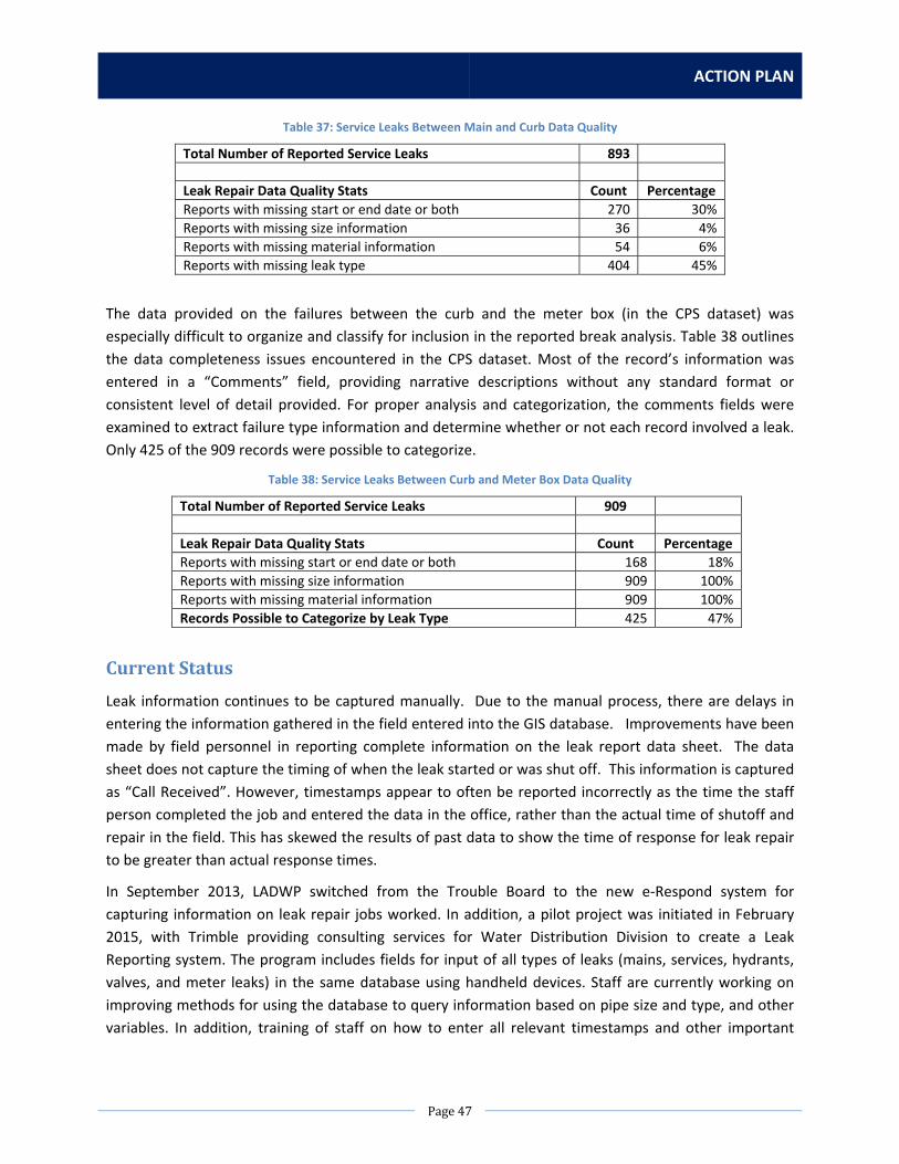
ACTION PLAN
Page47
Table 37: Service Leaks Between Main and Curb Data Quality
Total Number of Reported Service Leaks 893
Leak Repair Data Quality Stats Count Percentage
Reports with missing start or end date or both 270 30%
Reports with missing size information 36 4%
Reports with missing material information 54 6%
Reports with missing leak type 404 45%
The data provided on the failures between the curb and the meter box (in the CPS dataset) was
especially difficult to organize and classify for inclusion in the reported break analysis. Table 38 outlines
the data completeness issues encountered in the CPS dataset. Most of the record’s information was
entered in a “Comments” field, providing narrative descriptions without any standard format or
consistent level of detail provided. For proper analysis and categorization, the comments fields were
examined to extract failure type information and determine whether or not each record involved a leak.
Only 425 of the 909 records were possible to categorize.
Table 38: Service Leaks Between Curb and Meter Box Data Quality
Total Number of Reported Service Leaks 909
Leak Repair Data Quality Stats Count Percentage
Reports with missing start or end date or both 168 18%
Reports with missing size information 909 100%
Reports with missing material information 909 100%
Records Possible to Categorize by Leak Type 425 47%
CurrentStatus
Leak information continues to be captured manually. Due to the manual process, there are delays in
entering the information gathered in the field entered into the GIS database. Improvements have been
made by field personnel in reporting complete information on the leak report data sheet. The data
sheet does not capture the timing of when the leak started or was shut off. This information is captured
as “Call Received”. However, timestamps appear to often be reported incorrectly as the time the staff
person completed the job and entered the data in the office, rather than the actual time of shutoff and
repair in the field. This has skewed the results of past data to show the time of response for leak repair
to be greater than actual response times.
In September 2013, LADWP switched from the Trouble Board to the new e‐Respond system for
capturing information on leak repair jobs worked. In addition, a pilot project was initiated in February
2015, with Trimble providing consulting services for Water Distribution Division to create a Leak
Reporting system. The program includes fields for input of all types of leaks (mains, services, hydrants,
valves, and meter leaks) in the same database using handheld devices. Staff are currently working on
improving methods for using the database to query information based on pipe size and type, and other
variables. In addition, training of staff on how to enter all relevant timestamps and other important

WATER LOSS TASK FORCE
Page48
information in the new system is ongoing. This program currently involves pilot testing six mobile
devices that are deployed with leak crews to enter information electronically instead of manually. This
mobile recording system will tie in to e‐Respond in Phase 2 of this pilot program.
ListofActions
NoAction
Summary of Impact
The primary challenge with the No Action option is that CUWCC Best Management Practices require
reporting an annual number of leaks and estimated volume loss. The volume loss is typically not
estimated on all leaks, only on some of the major leaks.
This lack of data and inability to report estimated water losses could jeopardize opportunities to get low
interest loans and grants from State and Federal government. California Proposition 1, which passed in
2014, is an example of potential loans and grants in which we would have difficulty meeting the
reporting requirements.
If there is no action, there will also continue to be a lag between capturing information in the field and
entering it into GIS.
Action 1: Develop a Second PilotMobile Leak Reporting System to Capture andUpdateLeakInformationinNear‐RealTime
Scope of Work
Implement a second automated leak reporting system pilot using Sedaru as a comparison with the
Trimble pilot. Handheld devices will be used by field staff to upload leak information directly into the
database in real time. Volume estimates will be automatically calculated based on variables inputted in
the field. This should correct current issues with timestamps being recorded as the incorrect time based
on when the staff person recorded the time in the office rather than the shutoff and repair time that
occurred in the field.
Staffing Needs
This action utilizes five water utility workers and one civil engineering associate. The technology may be
expanded in the future to gate crews and large valve operators that typically respond to leaks.
Equipment, Materials, Rentals, and Contract Needs
Equipment will consist of handheld mobile devices with broadband communication capability. This
equipment will run licensed software and possibly communicate to cloud based server. Six units are
planned to be purchased as a part of a pilot program. If the decision is made to implement the program
on a full‐scale basis, it is expected at least 40 devices will be needed for leak crews and support
personnel.
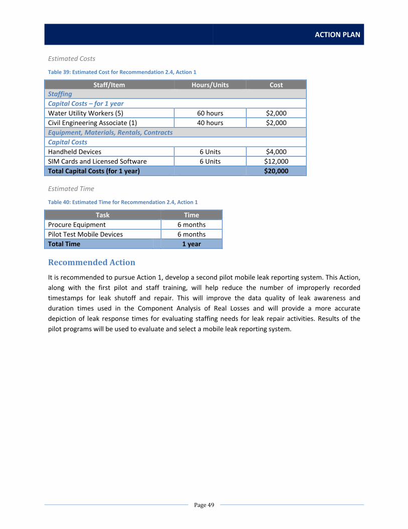
ACTION PLAN
Page49
Estimated Costs
Table 39: Estimated Cost for Recommendation 2.4, Action 1
Staff/Item Hours/Units Cost Staffing
Capital Costs – for 1 year
Water Utility Workers (5) 60 hours $2,000
Civil Engineering Associate (1) 40 hours $2,000
Equipment, Materials, Rentals, Contracts
Capital Costs
Handheld Devices 6 Units $4,000
SIM Cards and Licensed Software 6 Units $12,000
Total Capital Costs (for 1 year) $20,000
Estimated Time
Table 40: Estimated Time for Recommendation 2.4, Action 1
Task Time
Procure Equipment 6 months
Pilot Test Mobile Devices 6 months
Total Time 1 year
RecommendedAction
It is recommended to pursue Action 1, develop a second pilot mobile leak reporting system. This Action,
along with the first pilot and staff training, will help reduce the number of improperly recorded
timestamps for leak shutoff and repair. This will improve the data quality of leak awareness and
duration times used in the Component Analysis of Real Losses and will provide a more accurate
depiction of leak response times for evaluating staffing needs for leak repair activities. Results of the
pilot programs will be used to evaluate and select a mobile leak reporting system.

WATER LOSS TASK FORCE
Page50
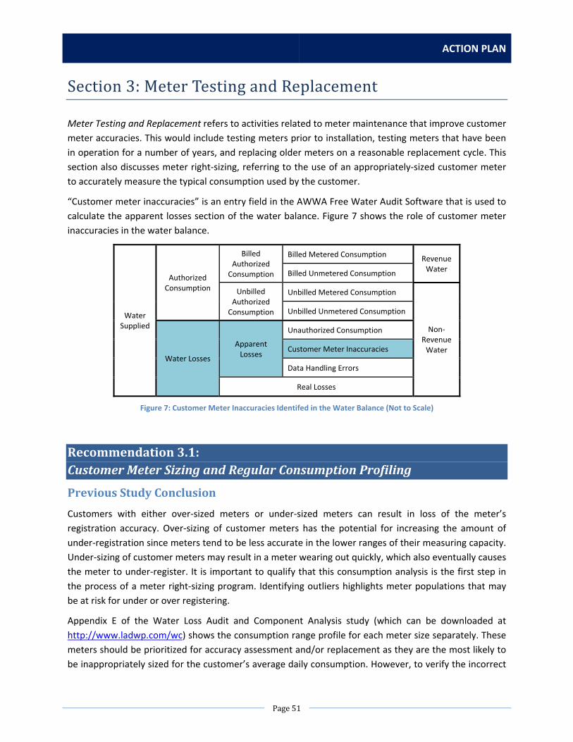
ACTION PLAN
Page51
Section3:MeterTestingandReplacement
Meter Testing and Replacement refers to activities related to meter maintenance that improve customer
meter accuracies. This would include testing meters prior to installation, testing meters that have been
in operation for a number of years, and replacing older meters on a reasonable replacement cycle. This
section also discusses meter right‐sizing, referring to the use of an appropriately‐sized customer meter
to accurately measure the typical consumption used by the customer.
“Customer meter inaccuracies” is an entry field in the AWWA Free Water Audit Software that is used to
calculate the apparent losses section of the water balance. Figure 7 shows the role of customer meter
inaccuracies in the water balance.
Water Supplied
Authorized Consumption
Billed Authorized Consumption
Billed Metered Consumption Revenue Water
Billed Unmetered Consumption
Unbilled Authorized Consumption
Unbilled Metered Consumption
Non‐Revenue Water
Unbilled Unmetered Consumption
Water Losses
Apparent Losses
Unauthorized Consumption
Customer Meter Inaccuracies
Data Handling Errors
Real Losses
Figure 7: Customer Meter Inaccuracies Identifed in the Water Balance (Not to Scale)
Recommendation3.1:CustomerMeterSizingandRegularConsumptionProfiling
PreviousStudyConclusion
Customers with either over‐sized meters or under‐sized meters can result in loss of the meter’s
registration accuracy. Over‐sizing of customer meters has the potential for increasing the amount of
under‐registration since meters tend to be less accurate in the lower ranges of their measuring capacity.
Under‐sizing of customer meters may result in a meter wearing out quickly, which also eventually causes
the meter to under‐register. It is important to qualify that this consumption analysis is the first step in
the process of a meter right‐sizing program. Identifying outliers highlights meter populations that may
be at risk for under or over registering.
Appendix E of the Water Loss Audit and Component Analysis study (which can be downloaded at
http://www.ladwp.com/wc) shows the consumption range profile for each meter size separately. These
meters should be prioritized for accuracy assessment and/or replacement as they are the most likely to
be inappropriately sized for the customer’s average daily consumption. However, to verify the incorrect

WATER LOSS TASK FORCE
Page52
sizing of a meter it is best to conduct consumption profiling that would record the exact 24‐hour
consumption profile of a specific meter.
Lastly, it’s also important to review this analysis with an understanding of the small meter sizing
parameters as dictated by fire flow requirements. Going forward, LADWP is planning to install small
meters no smaller than 1”, limiting the options in right‐sizing low consumption accounts.
CurrentStatus
WDD has a current contract with an outside vendor, who is reviewing LADWP’s large meter
maintenance and testing programs. Measuring elements of meters are being tested before installation
into the ground, and also testing a sample of measuring elements from meters of various ages, sizes,
and types.
In addition, WDD has procured a contract for a pilot Advanced Metering Infrastructure (AMI) project.
WDD is planning to install 525 units for this project. This infrastructure will allow LADWP to perform
more detailed consumption profiling.
However, it should be noted that there are significant constraints in potentially resizing a meter based
on consumption profiling results. When LADWP customers request domestic services, the Los Angeles
Department of Building and Safety (LADBS) must grant a plumbing permit. LADBS selects a meter and
service size based on the number of fixtures at the proposed/existing site.
Once the service and meter have been installed, the service size and meter size cannot be changed
without approval from LADBS. LADBS will not allow anyone to reduce the service/meter size unless
fixtures are actually removed from the existing buildings and a new reassessment procedure is
completed. Given the current LADBS rules and regulations, LADWP may not be able to reduce the meter
size or force the customer to buy a larger service.
Furthermore, downsizing or upsizing a meter could be infeasible depending on the specific situation. A
reducer could be used to downsize a meter on a larger service line, but this could violate LADBS and
LAFD requirements for meter sizing and minimum fire flow. LADBS code also sizes meters by number of
plumbing fixtures on site. In order to upsize a meter, a new service line would need to be installed,
which could cost a few thousand dollars in piping costs, plus labor costs.
ListofActions
NoAction
Summary of Impact
LADWP would continue to use the data from the FY 2010‐2011 consumption profiling performed in the
previous study, which is fast becoming outdated information. However, information from other
currently ongoing pilot programs may provide more updated information on consumption patterns for a
focused set of LADWP customers.

ACTION PLAN
Page53
Action 1: Update FY 2010‐2011 Consumption Profiling and InvestigateProblematicMetersIdentified
Scope of Work
The new consumption profile would be for the latest fiscal year for which a full set of consumption data
is available. ITS staff would provide the raw data set for the consumption volumes for each meter for
each billing period. Due to staffing limitations and resource constraints, a consultant would need to be
hired to perform the data analysis of the consumption profiling.
The final consumption profile would be sent to Water Distribution Division, with specific meters that
were presented as outliers identified for follow‐up. WDD would either perform a field test for smaller
meters, or pull the meter and place it on a test bench at a DWP facility.
Staffing Needs
One senior systems analyst would be required to provide the raw data set. The number of meters
identified as outliers could vary, therefore, in order to provide an estimate of staff needs from WDD, it is
estimated that 1 water service worker would be needed to check around 1,800 meters per year. This
number is based on the number of non‐zero meter outliers identified in the previous FY 2010‐2011
Water Loss Audit consumption profile, but this may or may not be representative of the actual number
of meters that need to be checked depending on the updated results of the proposed new profile. In
addition, water service specialists would be needed to bench test meters. For an approximate 50% of
those outlier meters identified as an estimate that would need to be bench tested, one water service
specialist would be needed.
Equipment, Materials, Rentals, and Contract Needs
A contract would be needed to perform the consumption profiling. Three light utility trucks will also be
needed.
Estimated Costs
Table 41: Estimated Cost for Recommendation 3.1, Action 1
Staff/Item Hours/Units Cost Staffing
Capital Costs – for 1 month
Senior Systems Analyst (1) 160 hours $9,000
Operations & Maintenance Costs – per year
Water Service Worker (1) 2,080 hours $78,000
Water Service Specialist (1) 2,080 hours $82,000
Equipment, Materials, Rentals, Contracts
Capital Costs
Contract 1 unit $50,000
Light Service Utility Truck 1 unit $56,000
Total Capital Costs (for 1 month) $115,000
Total Operations & Maintenance Costs (per year) $160,000

WATER LOSS TASK FORCE
Page54
Estimated Time
Table 42: Estimated Time for Recommendation 3.1, Action 1
Task Time
Data Collection 1 month
Contract Procurement 6 months
Consumption Profile 2 months
Meter Outlier Follow‐Up Ongoing
Total Time 9 months + ongoing
Note that the time to purchase a truck, which could take up to 3‐4 years, was not included in this
estimated timeline.
RecommendedAction
It is recommended to go with the No Action option due to concerns about the ability to make changes to
existing meters. The pilot programs that are already ongoing will provide more detailed consumption
profiling information that can be used as a small‐scale evaluation.
Recommendation3.2:TestingofSmallCustomerMeters
PreviousStudyConclusion
LADWP should continue regular testing of random small meter samples. Regular testing will allow
tracking of the average accuracy of each size/make group of meters. With this type of monitoring,
LADWP will be able to initiate meter replacement when a certain meter size/make group reaches the
threshold where meter replacement becomes an economically viable option.
In order to proactively manage the small meter population, LADWP should continue regular testing of
random small meter samples (100 to 200 meters per year). Regular random testing will allow tracking of
the average accuracy of each of the size/make groups of meters. With this type of monitoring, LADWP
will be able to initiate meter replacement when a certain meter make/size group reaches the threshold
where meter replacement becomes an economically viable option.
CurrentStatus
WDD Meter and Service Section currently tests all large (3”and larger) meters and 10% of all small
(5/8”x3/4” to 2”) meters prior to installation. The tests are to insure that the meters are performing to
manufacturer specifications. If a meter in the field is removed, it is generally more cost‐effective to
replace the unit rather than to test and re‐install the meter. There is currently no meter testing of
representative samples of meters already in service, but this is being addressed by meter replacement
goals.

ACTION PLAN
Page55
According to the industry standard, the life expectancy of small meters is 10‐20 years. The current
meter replacement cycle is approximately 27 years based on 25,000 small meter annual replacement
goals. The goal was determined by the number of personnel available for meter replacement.
The top 400 large meters by consumption are overhauled (measuring elements, gaskets, and
occasionally the registers are replaced) at a frequency of 6 months to five years, based on consumption.
ListofActions
NoAction
Summary of Impact
No additional bench testing of a representative sample of small meters would be pursued. WDD would
continue with their annual replacement program of 25,000 small meters to help improve meter
accuracy. However, without bench test results, the current status of the meter accuracy of the small
meter base would be unknown and would have to be estimated based on results from the previous
study.
Action 1: Implement Meter Testing of a Representative Sample of 1,000 OperationalSmallMeters
Scope of Work
ITS would provide a sample list of 1,000 meters to be bench tested based on data found in CCB. These
1,000 meters should be representative of the size, age, and make of the entire small meter stock, and
then randomly selected.
The 1,000 meters would have to be removed from the field and replaced with new meters and Itron
ERTs. The Water Service Workers would data capture the new meter data as well as the out read of old
meter on his/her assigned mobile data terminal (MDT). The sample of 1,000 meters pulled would not be
placed back into the field following bench testing as the new meters they were replaced with will
become the new permanent meters for those customers.
All removed meters would be delivered to the Water Service Specialist assigned to the testing facility.
Water Service Specialist would clean the meters and prepare them to be set and tested on the Meter
Shop test bench.
The actual percentage of LADWP small meter population by size is as follows:
5/8” x 3/4” meters = 25%
3/4” x 1”meters = 43%
1” meters = 20%
1‐1/2”meters =7%
2”meters = 5%
The meter sizes removed from the field for testing would mirror LADWP’s actual meter population
percentages.
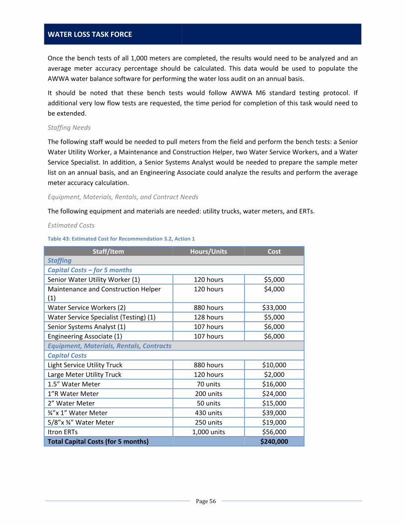
WATER LOSS TASK FORCE
Page56
Once the bench tests of all 1,000 meters are completed, the results would need to be analyzed and an
average meter accuracy percentage should be calculated. This data would be used to populate the
AWWA water balance software for performing the water loss audit on an annual basis.
It should be noted that these bench tests would follow AWWA M6 standard testing protocol. If
additional very low flow tests are requested, the time period for completion of this task would need to
be extended.
Staffing Needs
The following staff would be needed to pull meters from the field and perform the bench tests: a Senior
Water Utility Worker, a Maintenance and Construction Helper, two Water Service Workers, and a Water
Service Specialist. In addition, a Senior Systems Analyst would be needed to prepare the sample meter
list on an annual basis, and an Engineering Associate could analyze the results and perform the average
meter accuracy calculation.
Equipment, Materials, Rentals, and Contract Needs
The following equipment and materials are needed: utility trucks, water meters, and ERTs.
Estimated Costs
Table 43: Estimated Cost for Recommendation 3.2, Action 1
Staff/Item Hours/Units Cost Staffing
Capital Costs – for 5 months
Senior Water Utility Worker (1) 120 hours $5,000
Maintenance and Construction Helper (1)
120 hours $4,000
Water Service Workers (2) 880 hours $33,000
Water Service Specialist (Testing) (1) 128 hours $5,000
Senior Systems Analyst (1) 107 hours $6,000
Engineering Associate (1) 107 hours $6,000
Equipment, Materials, Rentals, Contracts
Capital Costs
Light Service Utility Truck 880 hours $10,000
Large Meter Utility Truck 120 hours $2,000
1.5” Water Meter 70 units $16,000
1”R Water Meter 200 units $24,000
2” Water Meter 50 units $15,000
¾”x 1” Water Meter 430 units $39,000
5/8”x ¾” Water Meter 250 units $19,000
Itron ERTs 1,000 units $56,000
Total Capital Costs (for 5 months) $240,000

ACTION PLAN
Page57
Estimated Time
Table 44: Estimated Time for Recommendation 3.2, Action 1
Task Time
Create Meter Sample List 1 month
Pull Meters from Field 2 months
Bench Test Meters 2 months
Analyze Results 1 month
Total Time 4 months
Pulling meters and bench testing will be performed concurrently, so the total time is 4 months. Note
that the time to purchase additional trucks, which could take up to 3‐4 years, was not included in this
estimated timeline.
Action 2: Implement Meter Testing of a Representative Sample of 12,000 OperationalSmallMeters
Scope of Work
The 12,000 meters would have to be removed from the field and replaced with new meters and Itron
ERTs. The Water Service Workers would data capture the new meter data as well as the out read of old
meter on his/her assigned MDT. The sample of 12,000 meters pulled would not be placed back into the
field following bench testing as the new meters they were replaced with will become the new
permanent meters for those customers.
All removed meters would be delivered to the Water Service Specialist assigned to the testing facility.
Water Service Specialist would clean the meters and prepare them to be set and tested on the Meter
Shop test bench.
The actual percentage of LADWP small meter population by size is as follows:
5/8” x 3/4” meters = 25%
3/4” x 1”meters = 43%
1” meters = 20%
1‐1/2”meters =7%
2”meters = 5%
The meter sizes removed from the field for testing would mirror LADWP’s actual meter population
percentages.
Staffing Needs
The following staff would be needed: Senior Water Utility Worker, Maintenance and Construction
Helper, Water Service Worker, and Water Service Specialist.
Equipment, Materials, Rentals, and Contract Needs
The following equipment and materials are needed: utility trucks, water meters, and ERTs.
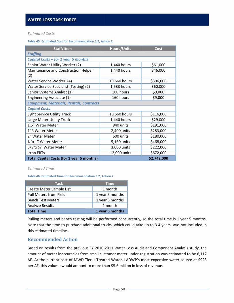
WATER LOSS TASK FORCE
Page58
Estimated Costs
Table 45: Estimated Cost for Recommendation 3.2, Action 2
Staff/Item Hours/Units Cost Staffing
Capital Costs – for 1 year 5 months
Senior Water Utility Worker (2) 1,440 hours $61,000
Maintenance and Construction Helper (2)
1,440 hours $46,000
Water Service Worker (4) 10,560 hours $396,000
Water Service Specialist (Testing) (2) 1,533 hours $60,000
Senior Systems Analyst (1) 160 hours $9,000
Engineering Associate (1) 160 hours $9,000
Equipment, Materials, Rentals, Contracts
Capital Costs
Light Service Utility Truck 10,560 hours $116,000
Large Meter Utility Truck 1,440 hours $29,000
1.5” Water Meter 840 units $191,000
1”R Water Meter 2,400 units $283,000
2” Water Meter 600 units $180,000
¾”x 1” Water Meter 5,160 units $468,000
5/8”x ¾” Water Meter 3,000 units $222,000
Itron ERTs 12,000 units $672,000
Total Capital Costs (for 1 year 5 months) $2,742,000
Estimated Time
Table 46: Estimated Time for Recommendation 3.2, Action 2
Task Time
Create Meter Sample List 1 month
Pull Meters from Field 1 year 3 months
Bench Test Meters 1 year 3 months
Analyze Results 1 month
Total Time 1 year 5 months
Pulling meters and bench testing will be performed concurrently, so the total time is 1 year 5 months.
Note that the time to purchase additional trucks, which could take up to 3‐4 years, was not included in
this estimated timeline.
RecommendedAction
Based on results from the previous FY 2010‐2011 Water Loss Audit and Component Analysis study, the
amount of meter inaccuracies from small customer meter under‐registration was estimated to be 6,112
AF. At the current cost of MWD Tier 1 Treated Water, LADWP’s most expensive water source at $923
per AF, this volume would amount to more than $5.6 million in loss of revenue.
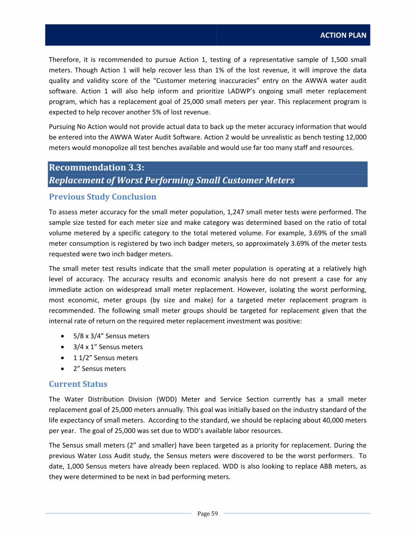
ACTION PLAN
Page59
Therefore, it is recommended to pursue Action 1, testing of a representative sample of 1,500 small
meters. Though Action 1 will help recover less than 1% of the lost revenue, it will improve the data
quality and validity score of the “Customer metering inaccuracies” entry on the AWWA water audit
software. Action 1 will also help inform and prioritize LADWP’s ongoing small meter replacement
program, which has a replacement goal of 25,000 small meters per year. This replacement program is
expected to help recover another 5% of lost revenue.
Pursuing No Action would not provide actual data to back up the meter accuracy information that would
be entered into the AWWA Water Audit Software. Action 2 would be unrealistic as bench testing 12,000
meters would monopolize all test benches available and would use far too many staff and resources.
Recommendation3.3:ReplacementofWorstPerformingSmallCustomerMeters
PreviousStudyConclusion
To assess meter accuracy for the small meter population, 1,247 small meter tests were performed. The
sample size tested for each meter size and make category was determined based on the ratio of total
volume metered by a specific category to the total metered volume. For example, 3.69% of the small
meter consumption is registered by two inch badger meters, so approximately 3.69% of the meter tests
requested were two inch badger meters.
The small meter test results indicate that the small meter population is operating at a relatively high
level of accuracy. The accuracy results and economic analysis here do not present a case for any
immediate action on widespread small meter replacement. However, isolating the worst performing,
most economic, meter groups (by size and make) for a targeted meter replacement program is
recommended. The following small meter groups should be targeted for replacement given that the
internal rate of return on the required meter replacement investment was positive:
5/8 x 3/4” Sensus meters
3/4 x 1” Sensus meters
1 1/2” Sensus meters
2” Sensus meters
CurrentStatus
The Water Distribution Division (WDD) Meter and Service Section currently has a small meter
replacement goal of 25,000 meters annually. This goal was initially based on the industry standard of the
life expectancy of small meters. According to the standard, we should be replacing about 40,000 meters
per year. The goal of 25,000 was set due to WDD’s available labor resources.
The Sensus small meters (2” and smaller) have been targeted as a priority for replacement. During the
previous Water Loss Audit study, the Sensus meters were discovered to be the worst performers. To
date, 1,000 Sensus meters have already been replaced. WDD is also looking to replace ABB meters, as
they were determined to be next in bad performing meters.

WATER LOSS TASK FORCE
Page60
ListofActions
NoAction
Summary of Impact
If the worst performing small meters are not replaced, the total customer meter base will continue to
perform at less accurate levels. Replacing the specific meters identified would improve the overall
customer meter accuracy level significantly. However, LADWP would continue its goal to replace 25,000
priority small meters on an annual basis, thereby increasing customer meter accuracy each year.
Action1:ReplaceAlloftheWorstPerformingSmallMeters
Scope of Work
There are 32,000 Sensus small meters in the distribution system to be replaced. Some of these meters
can be addressed through WDD Meter and Service Section’s annual Meter Replacement Program (MRP).
The annual goal of the MRP is the replacement of 25,000 small meters. The priority is to replace stuck
or defective meters as the potential for revenue recovery is greater than replacement of the worst‐
performing meters that are not stuck or otherwise defective. The stuck or defective meters may not be
Sensus meters. The way to ensure that the Sensus meters are being replaced would be to dedicate
resources strictly for the Sensus meters. 10 Water Service Workers should be able to replace the meters
within 2 years.
Staffing Needs
One additional Clerk typist would be needed to research meter information, create Field Activities (F/As)
in CCB, and to data capture and track meter changes in WMIS. 10 additional Water Service Workers (2
per district) will perform the meter changes at a rate of 8 meters, per Service Worker, per day.
Equipment, Materials, Rentals, and Contract Needs
32,000 Neptune meters, sizes 5/8”‐1.5”, 32,000 Itron Encoder Receiver Transmitters (ERTs), and 64,000
meter gaskets, sizes ¾”‐1.5”, will need to be purchased. Each Water Service Worker will need a Light
Service Utility Truck. Each Water Service Worker will need a mobile data terminal (MDT) to receive F/As
and to input meter information.

ACTION PLAN
Page61
Estimated Costs
Table 47: Estimated Cost for Recommendation 3.3, Action 1
Staff/Item Hours/Units Cost Staffing
Capital Costs – for 1 year 8 months
Clerk Typist (1) 3,536 hours $70,000
Water Service Worker (10) 32,865 hours $1,589,000
Equipment, Materials, Rentals, Contracts
Capital Costs
Light Service Utility Truck 10 units $559,000
1.5” Water Meter 1,104 units $251,000
1”R Water Meter 12,519 units $1,477,000
2” Water Meter 730 units $219,000
¾”x 1” Water Meter 7,746 units $703,000
5/8”x ¾” Water Meter 9,900 units $733,000
Itron ERTs 32,000 units $2,240,000
Total Capital Costs (for 1 year 8 months) $7,841,000
Estimated Time
Table 48: Estimated Time for Recommendation 3.3, Action 1
Task Time
Installation and Data Capturing 1 year 8 months
Total Time 1 year 8 months
Note that the time to purchase additional trucks, which could take up to 3‐4 years, was not included in
this estimated timeline.
RecommendedAction
Based on results from the previous FY 2010‐2011 Water Loss Audit and Component Analysis study, the
amount of meter inaccuracies from small customer meter under‐registration was estimated to be 6,112
AF. At the current cost of MWD Tier 1 Treated Water, LADWP’s most expensive water source at $923
per AF, this volume would amount to more than $5.6 million in loss of revenue.
Pursuing Action 1 will increase meter accuracy and recover potential lost revenue due to under‐
registration of poor‐performing meters. It is estimated that Action 1 could help recover up to 5% of the
lost revenue. However, Action 1 is only recommended after an initial round of meter sampling is
completed as suggested in Recommendation 3.2, Action 1. The results of the testing of 1,500 small
meters will provide an updated profile of the meter stock and could potentially change (or otherwise
validate) the results of which meters are worst performing from the previous sampling completed for
the FY 2010‐2011 Water Loss Audit and Component Analysis study. The scope of work and estimated
costs for Action 1 will likely change after the new testing results are received.
WATER LOSS TASK FORCE
Page62
Therefore, it is recommended to take the No Action option until the meters can be re‐evaluated. Should
Action 1 be deployed following re‐assessment, it will improve the data quality and validity score of the
“Customer metering inaccuracies” entry on the AWWA water audit software.
Recommendation3.4:LargeMeterMaintenanceScheduleOverhaul
PreviousStudyConclusion
For the top one hundred large customer meters (ranked by revenue generated), it is recommended to
undertake consumption profiling and targeted selection of appropriate metering technology. An
improvement of 1% in metering accuracy (achievable by switching from a standard compound meter to
an electromagnetic flow meter, for example) will result in significant revenue increases for these meters.
For the large meter population, LADWP should aim to adopt a large meter maintenance program that
compares consumption and revenue data to overhaul costs for an overhaul schedule that optimizes
savings. To institutionalize this approach with an appreciation for labor constraints and a pending new
central database, the FY2010‐11 Water Loss Audit and Component Analysis Study recommended that
LADWP pursue the new large meter maintenance program in the following three phases:
Phase One: To start the process of adopting this approach, it is recommended to select and
implement Scenario #2 in Section 10.2 of the Water Loss Audit and Component Analysis study
(which can be downloaded at http://www.ladwp.com/wc), without the sewer service charge
considerations. This would require overhauling about 20 more large meters than the 153
overhauls completed in FY 2010‐2011. Scenario #2 offers an advantageous starting point in that
it does not require LADWP to test significantly more meters than tested in 2011.
Phase Two: With the adoption of the new central database and preparation of sufficient labor
resources, it is recommended to adopt Scenario #2 with sewer service rate charge
considerations. This will require significantly more overhauls per year but will be based on a
more complete cost benefit analysis when taking the sewer service revenue losses into account.
Phase Three: Down the line, after institutionalizing this consumption based approach for
designing the annual meter overhaul programs, it is recommended to fine tune the approach by
revisiting the under‐registration assumptions. Toward this end, completing more meter accuracy
testing as a component of the overhaul process is recommended. This will provide trend data
that will allow for better understanding of how the large meter’s accuracy decreases between
testing intervals.
CurrentStatus
Water Distribution Division (WDD) Meter and Service Section has a long history of performing
maintenance on the unitized measuring elements (UME) of its large meter base to help maintain their
accuracy. However, much of the knowledge that had been gained was disrupted when its large meter
base was replaced between 2003 and 2010. Updated meter technology and different meter vendors

ACTION PLAN
Page63
normally make previous knowledge less relevant and useful. As a result of the Water Loss Audit, WDD
Meter and Service Section staffing and other priorities limit large meter measuring element
maintenance to about 150 meters per year. In 2013, immediately following the completion of the
previous FY 2010‐2011 Water Loss Audit and Component Analysis study, LADWP’s large meter
maintenance schedule was overhauled so that the top 400 users have their meter maintained on a 6
month to 5 year frequency. WDD Meter and Service would like to maintain the remaining 6,300 large
meter base on as 8 to 10 year cycle. As currently staffed, it would take nearly 45 years to work through
the entire meter base.
ListofActions
NoAction
Summary of Impact
Since the large meter maintenance schedule has already been overhauled to reflect the
recommendations from the previous study, large meter accuracy is already expected to improve.
However, this would not be confirmed without analyzing available test results.
Action 1: Analyze Large Meter Test Results from Recent Years to Provide aVolumeWeightedAverageAccuracy
Scope of Work
When a large meter is scheduled to be overhauled, the crew takes new or rebuilt UMEs to the work
location. The old UME is removed, the new unit is installed, the old unit is returned to the meter shop,
tested, and data is stored. This data has been stored for approximately the last 18 months. Once a
sufficient amount of data is accumulated (about two years) the results can be analyzed. Therefore, the
data analysis will be performed every 2 years.
Since the data is currently stored as hard copies only, the data would need to be transferred manually to
an electronic format for data analysis. This could be time consuming. It is recommended that WDD
organize a program in the future to populate the data electronically on a regular basis rather than
waiting until a data analysis needs to be performed.
Staffing Needs
One Water Service Specialist will be required to analyze the results.
Equipment, Materials, Rentals, and Contract Needs
One laptop computer will be needed.

WATER LOSS TASK FORCE
Page64
Estimated Costs
Table 49: Estimated Cost for Recommendation 3.4, Action 1
Staff/Item Hours/Units Cost
Staffing
Capital Costs – for 1 month
Water Service Specialist 80 hours $3,000
Equipment, Materials, Rentals, Contracts
Capital Costs
Laptop Computer 1 unit $1,000
Total Capital Costs (for 1 month) $4,000
Estimated Time
Table 50: Estimated Time for Recommendation 3.4, Action 1
Task Time
Purchase Laptop 1 month
Accumulate Data 2 years
Analyze Results 1 month
Total Time 2 years 2 months
RecommendedAction
Based on results from the previous FY 2010‐2011 Water Loss Audit and Component Analysis study, the
amount of meter inaccuracies from large customer meter under‐registration was estimated to be 1,118
AF. At the current cost of MWD Tier 1 Treated Water, LADWP’s most expensive water source at $923
per AF, this volume would amount to approximately $1 million in loss of revenue. It is estimated that the
large meter maintenance schedule overhaul that already occurred helps save 12% of this lost revenue.
It is recommended to pursue Action 1, analyze meter test results, as it will improve the data quality and
validity score of the “Customer metering inaccuracies” entry on the AWWA water audit software. The
estimated costs for Action 1 are minimal, and this action utilizes data that is already available.

ACTION PLAN
Page65
Section4:LeakDetectionandPrevention
Leak Detection and Prevention refers to actions taken to try to prevent water losses from leaks (also
known as “real losses”). These actions may include leak detection surveys, pressure management
studies, and increased infrastructure improvements. Economic analyses are performed to determine the
extent of leak detection and prevention measures that should be implemented in a cost‐effective
manner. LADWP is responsible for maintenance of all pipelines from the beginning of the distribution
system up to the customer meter, including over 7,200 miles of mainline pipe.
Real losses are categorized as reported leaks, unreported leaks, and background leaks:
Reported Leaks are defined by AWWA as: “leaks reported by customers, traffic authorities, or
any other outside party because of their visible and/or disruptive nature.” Reported leaks tend
to have high flow rates and relatively short durations because utilities like LADWP respond
quickly to shut‐off the leak and perform repairs.
Unreported Leaks are defined by AWWA as: “leaks that escape public knowledge and are only
identified through the active leakage control work of the utility.” Unreported leaks tend to have
moderate flow rates and the run time depends on the intervention policy. Acoustic leak
detection through leak survey is a commonly used method to search out unreported leaks.
Background Leaks are defined by AWWA as: “leaks involving the tiny weeps and seeps at joints
and fittings that defy detection through conventional acoustic means.” Background leaks tend to
have small flow rates and are continuously running. Background leakage is generally
unavoidable outside of prevention activities attributed to pressure management and
infrastructure replacement.
Real losses are calculated from the water balance by subtracting the authorized consumption and
apparent losses from the system input volume as shown in Figure 8. It is important that all of the values
entered for the water balance are accurate in order to result in a confident calculation of real loss
volume.
Water Supplied
Authorized Consumption
Billed Authorized Consumption
Billed Metered Consumption Revenue Water
Billed Unmetered Consumption
Unbilled Authorized Consumption
Unbilled Metered Consumption
Non‐Revenue Water
Unbilled Unmetered Consumption
Water Losses
Apparent Losses
Unauthorized Consumption
Customer Meter Inaccuracies
Data Handling Errors
Real Losses
Figure 8: Real Losses Identified in the Water Balance (Not to Scale)

WATER LOSS TASK FORCE
Page66
The previous FY 2010‐2011 Water Loss Audit and Component Analysis study evaluated economically
efficient real loss reduction strategies, as shown in Figure 9.
Figure 9: Four‐Component Tool Box for Intervention against Real Losses
Three of the strategies – improved pressure management, improved response time for leak repair, and
increased leak detection activity – are detailed and evaluated in Sections 4.1, 4.2, and 4.3 of this Action
Plan based on recommendations from the previous FY 2010‐2011 study. The fourth strategy – improved
system maintenance and increased infrastructure rehabilitation – is not evaluated in this Action Plan as
the previous study concluded there was no immediate need for LADWP to further increase the
replacement of infrastructure strictly for a leakage management gain. This was due to the fact that
LADWP has plans to increase its infrastructure replacement program, as well as the fact that LADWP has
a relatively low level of leakage, an overall low break frequency for the system, and the fact that
infrastructure replacement is the most expensive option/strategy for real loss reduction. Despite this
and in light of the current drought, LADWP has further increased its plans for infrastructure
replacement. However, it is estimated that LADWP will need an additional $1.3 billion in funding to
reduce its current pipe replacement cycle to improved levels outlined by LADWP’s infrastructure
management goals.
UnavoidableReal
Losses
Improved response time for
leak repair
Increased leak detection activity
Improved system
maintenance and
increased infrastructure
rehab
Improved pressure
management
Current Leakage Level
Economic Leakage LevelILI = 1.0

ACTION PLAN
Page67
Recommendation4.1:PressureManagementImprovementandPilotStudy
PreviousStudyConclusion
Pressure management is already partially being employed by LADWP through the use of hydraulic zones,
known as “service zones”, within its distribution system where Pressure Reducing Valve (PRV) stations
are operated. LADWP currently has 124 service zones and 423 PRVs in its distribution system. The
current average system pressure is 90 psi, which indicates that there is room for improved pressure
management.
Various improvements to current pressure management practices were investigated for their
implementation cost and potential to reduce the average system pressure (and consequently reduce
water loss). It was assumed that the reduction of average system pressure would be achieved through
three steps, where each step builds upon the results of the previous step and reduces the average
system pressure further through additional system upgrades and investments. The three steps should
be implemented over an eight‐year period.
Step 1: In 2011, LADWP operated a total of 124 service zones within its distribution network.
Out of these 124 service zones, 65 service zones have average system pressures above 100 psi.
These 65 service zones were selected for implementation of the three‐step pressure
management program described in this section (see Appendix V of the previous FY 2010‐2011
Water Loss Audit and Component Analysis study for the list of prioritized 65 service zones).
Through a detailed assessment of current system pressure levels, pump operation, reservoir
operation, pressure transients, PRV settings, validation of service zone boundary valves and
replacement of valves where necessary, and an update of hydraulic models, this step will lay the
ground work for the implementation of step 2 and 3. Step 1 will also include optimization of
current PRV settings and operations. The first pressure reduction step will be achieved by
implementing the following actions:
• System Pressure Study and high frequency pressure logging for detection of transients
with 390 pressure logging sites throughout the 65 service zones
• Review and update the detailed inventory of all PRV's, tank level settings and controls,
pumping regimes and boundary valves
• Validation of service zone boundary valves by identifying and sounding all boundary
valves
• Replacement of boundary valves, assuming two per service zone
• Update hydraulic models with system pressure study
• LADWP general engineering and project management
• Adjustment of Current PRV settings and pumps and tank levels to optimum, where
feasible
It was assumed that in each of the 65 service zones targeted for optimized pressure
management the average pressure could be reduced by 4% by adjusting current PRV settings,

WATER LOSS TASK FORCE
Page68
pump control and tank levels. Step 1 would result in a system wide average pressure reduction
of 3 psi. This would reduce the total real loss volume by 204 MGY (or 626.05 AFY).
Step 2: Building upon the detailed assessment undertaken in Step 1, Step 2 reduces the system
pressure further through the implementation of advanced flow modulated pressure control. The
second pressure reduction step will be achieved by implementing the following actions:
• Replace existing lead PRVs with Cla‐Val Model 98‐06 (or similar) PRVs, which allow
regulating pressure according to system demand. High pressure is provided when
system demand is high and pressure is lowered when system demand is low. A high
pressure set point is selected for high flow demand and a low pressure set point is
selected for low flow demand. This dual set point arrangement allows for reduction in
water loss by reducing system pressures during times of low demand, while still
providing adequate pressure during high or fire demand. It was assumed that an
average 3 PRV’s per service zone (177 in total) would be replaced or retrofitted to be
able to introduce demand based pressure control.
• Installation of new PRVs
• Pressure management engineering consultant for setting the PRVs, analyzing data and
results, and managing the project
• LADWP general engineering and project management
Step 2 would achieve a reduction in system wide average pressure of 3 psi, plus the 3 psi of
average system pressure reduction achieved in Step 1. In total, this would reduce the total real
loss volume by 408 MGY (or 1,252.11 AFY).
Step 3: Building upon Steps 1 and 2, Step 3 will further reduce the system pressure by splitting
zones 1134, 1123, 579, 1000, 1449, and 426 (service zones with more than 150 miles of
distribution network) into subzones for better pressure control in those large zones. It was
assumed that 15 new subzones would be created. Each of the new service zones will have an
average of 3 PRV chambers controlling the pressure for each zone. The third pressure reduction
step will be achieved by implementing the following actions:
• 90 PRV’s of size 6 inch and 8 inch
• Installation of new PRVs
• Service zone PRV chambers – 45 in total
• Replacement of boundary valves and installation of new boundary valves – 150 in total
• Pressure management engineering consultant for setting the PRVs, analyzing data and
results, and managing the project
• LADWP general engineering and project management
• Hydraulic Model for design of 15 zones
• Cost for distribution piping reconfiguration associated to creation of 15 new zones
Step 3 would achieve a reduction in system wide average pressure of 3 psi, plus the 6 psi of
average system pressure reduction achieved in step 1 and 2. In total, this would reduce the total
real loss volume by 544 MGY (1,669.47 AFY).

ACTION PLAN
Page69
CurrentStatus
Asset Management Group is currently assessing the correlation between high pressure and leaks.
Available technologies are being assessed to compile data in determining effects of high pressure on
leaks. Data collection is crucial in this study.
In general, trunk lines (pipes 24 inches or larger in diameter) are sized for a maximum head loss of 3 feet
per 1000‐foot of length. Distribution mains are sized for approximately 5 to 7 feet of head loss per
1000‐foot length. This is to maximize the hydraulic grade and pressure as supply is delivered throughout
the water system. A minimum pressure of 43 psi is required. Customer connections with less than 35
psi require a service elevation agreement. Customer service connections with greater than 80 psi
require a pressure regulator.
Given the geography of the City of LA, service areas within service zones may have significant elevation
differences. Areas with the highest elevations experience the lowest static pressures. Areas with the
lowest elevations experience the highest static pressures. In addition, the areas with the lowest
operational grades are typically the areas furthest from the trunk lines and furthest from the source of
supply.
In the San Fernando Valley for example, the 1123‐ft and 1134‐ft service zones are gravity systems. The
northernmost sections of the service zones where the elevations are high typically experience the
minimum 43 psi pressure. As the elevation continues to slope down onto the Valley floor, pressures
increase to over 80 psi and greater. The pipes for these areas are designed to handle the higher
pressures. As elevations increase going into the Santa Monica Mountains, the pressures decrease back
down to the minimum required pressure of 43 psi. As elevations increase further, the areas below 43
psi are moved over to the next service zone in a pump‐tank system. Typically, for these service zones,
the areas at the bottom of the hills are the ones experiencing the highest pressures.
Figure 10 is a static pressure map of LADWP’s water system, which represents the maximum static
pressure possible if a pipe existed. The maximum static pressure was calculated by taking the difference
between the system zone and ground elevation (also taking into account that pipe usually is installed
with a cover of 3 feet) and multiplying the difference by 0.433 to convert to pounds per square inch.
Again, this map only represents what the maximum static pressure would be if a pipe existed. That’s
why you will still see a color for areas that do not have pipe in the ground.
Figure 11 shows the areas of the city with the highest leak densities. Background colors of this map
represent the general leak density based on all leaks documented in GIS. These documented GIS leaks
go back to roughly 1990, but the completeness is questionable. Basically, not all leaks were
documented. The leak points (dots) shown on the map are from the year 2012. The reason this year
was used was because it represents a fairly complete set of data and the leak density areas, shown with
dark black borders, were based on these 2012 leak points.
Figure 12 shows the ground elevation based on the data received through the LARIAC program.
Specifically it was taken from the 2006 aerial imagery which was at a 2’ resolution.

WATER LOSS TASK FORCE
Page70
Figure 10: Static Pressure Map of LADWP’s Water System
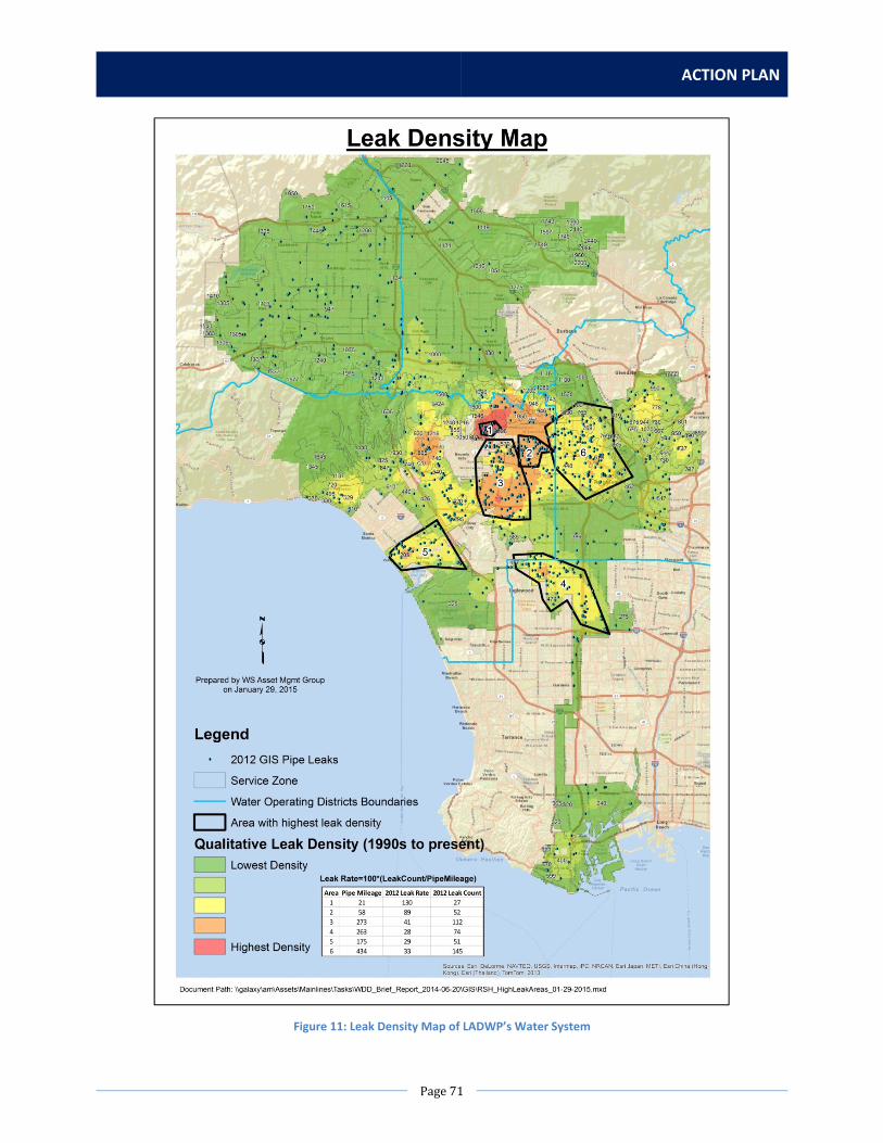
ACTION PLAN
Page71
Figure 11: Leak Density Map of LADWP’s Water System

WATER LOSS TASK FORCE
Page72
Figure 12: Ground Elevation Map of LADWP’s Water System

ACTION PLAN
Page73
ListofActions
NoAction
Summary of Impact
Current service zone pressures are strategically set to provide for domestic as well as fire protection use.
Reducing any pressures in any of the service zones will require extensive hydraulic system monitoring,
modeling, and analysis to determine impacts to existing service requirement and adjacent service zones.
Therefore a No Action Plan is a consideration.
Action1:Site‐Specific PressureMonitoringin13HighestLeakDensityAreas
Scope of Work
This action proposes to conduct further monitoring only in the 13 zones with highest leak densities. 20
pressure loggers will be installed at each service zone for one week during the high water demand
period, typically in the summer. Water Operations Division (WOD) staff estimate a hydrographer can
install 20 pressure loggers per day.
Once the data is retrieved, an engineer will analyze the pressure data and provide an analysis of trends.
The engineer will identify any anomalies in the data, and with the help of a drafting technician and GIS
data, determine if these anomalies warrant further study at specific infrastructure network locations.
Staffing Needs
A hydrographer will be needed for 2 months to install and remove pressure recorders, and extract data.
One engineer will perform an analysis of the pressure data collected and trends. One drafting technician
may be needed to provide GIS infrastructure data.
Equipment, Materials, Rentals, and Contract Needs
20 pressure loggers will be needed.
Estimated Costs
Table 51: Estimated Cost for Recommendation 4.1, Action 1
Staff/Item Hours/Units Cost Staffing
Capital Costs – for 6 months
Hydrographer (1) 230 hours $12,000
Engineer (1) 700 hours $39,000
Drafting Technician (1) 200 hours $8,000
Equipment, Materials, Rentals, Contracts
Capital Costs
Pressure Loggers 20 units $4,000
Total Capital Costs (for 6 months) $63,000

WATER LOSS TASK FORCE
Page74
Estimated Time
Table 52: Estimated Time for Recommendation 4.1, Action 1
Task Time
Procure and Install Pressure Loggers 2 months
Data Analysis 4 months
Total Time 6 months
Action2: Site‐Specific PressureMonitoring in13 HighestLeakDensityAreasand17 HighPressureServiceZoneswith HydraulicModeling
Scope of Work
This action proposes to conduct further monitoring in the 13 zones with highest leak densities and 17
zones with high pressure. 20 pressure loggers will be installed at each service zone for one week during
the high water demand period, typically in the summer. Water Operations Division (WOD) staff estimate
a hydrographer can install 20 pressure loggers per day.
Once the data is retrieved, engineers will analyze the data and make recommendations if pressure can
be reduced or zones can be subdivided. This involves creating and or updating existing models, and
analysis of all fire services and hydrants in the new zones for compliance. In order to perform this
analysis, engineering staff may need to work with WDD Water New Business Group, CSD Account
Services, ITS, and/or the Water Engineering and Technical Services (WETS) GIS Group to research and
confirm the number and location of fire services in each zone. Furthermore, the water system data
(including pipe infrastructure, elevations, grades, etc.) in WDD’s hydraulic model may need to be
updated with current GIS information from WETS GIS Group. Performing these updates and background
research, as well as uploading the pressure data from the loggers and performing the analysis of each
hydrant and individual fire service pressure (of which there could be hundreds or even thousands of
services in each zone), could be time consuming. The complete data analysis and hydraulic modeling is
estimated to take 3‐6 months per service zone.
Staffing Needs
A hydrographer will be needed for 3 months to install and remove pressure recorders, and extract data.
Two drafting technicians will be needed to layout pipe network using GIS data. Four engineers will
perform hydraulic modeling. The time required to complete tasks depends on allocation of resources.
The work will be spread over three years.
Equipment, Materials, Rentals, and Contract Needs
100 pressure loggers will be needed.
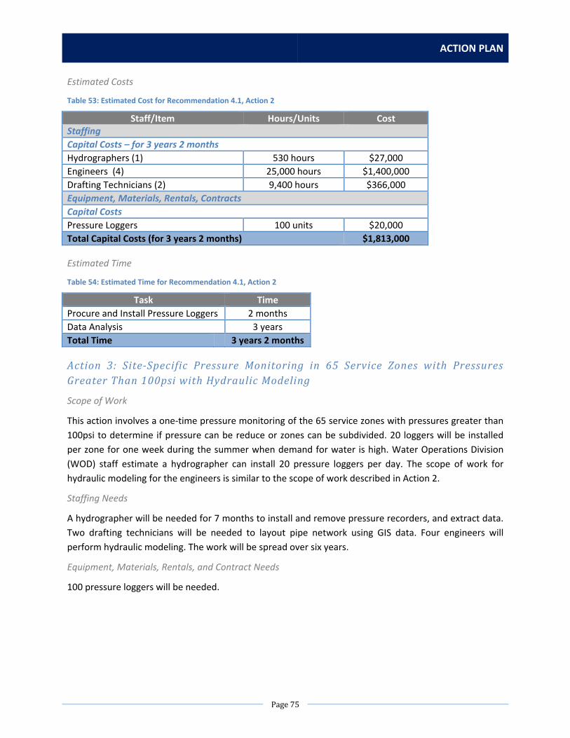
ACTION PLAN
Page75
Estimated Costs
Table 53: Estimated Cost for Recommendation 4.1, Action 2
Staff/Item Hours/Units Cost Staffing
Capital Costs – for 3 years 2 months
Hydrographers (1) 530 hours $27,000
Engineers (4) 25,000 hours $1,400,000
Drafting Technicians (2) 9,400 hours $366,000
Equipment, Materials, Rentals, Contracts
Capital Costs
Pressure Loggers 100 units $20,000
Total Capital Costs (for 3 years 2 months) $1,813,000
Estimated Time
Table 54: Estimated Time for Recommendation 4.1, Action 2
Task Time
Procure and Install Pressure Loggers 2 months
Data Analysis 3 years
Total Time 3 years 2 months
Action 3: Site‐Specific Pressure Monitoring in 65 Service Zones with PressuresGreaterThan100psiwithHydraulicModeling
Scope of Work
This action involves a one‐time pressure monitoring of the 65 service zones with pressures greater than
100psi to determine if pressure can be reduce or zones can be subdivided. 20 loggers will be installed
per zone for one week during the summer when demand for water is high. Water Operations Division
(WOD) staff estimate a hydrographer can install 20 pressure loggers per day. The scope of work for
hydraulic modeling for the engineers is similar to the scope of work described in Action 2.
Staffing Needs
A hydrographer will be needed for 7 months to install and remove pressure recorders, and extract data.
Two drafting technicians will be needed to layout pipe network using GIS data. Four engineers will
perform hydraulic modeling. The work will be spread over six years.
Equipment, Materials, Rentals, and Contract Needs
100 pressure loggers will be needed.

WATER LOSS TASK FORCE
Page76
Estimated Costs
Table 55: Estimated Cost for Recommendation 4.1, Action 3
Staff/Item Hours/Units Cost Staffing
Capital Costs – for 6 years 7 months
Hydrographer (1) 1,250 hours $55,000
Engineers (4) 56,000 hours $3,200,000
Drafting Technicians (2) 21,000 hours $800,000
Equipment, Materials, Rentals, Contracts
Capital Costs
Pressure Loggers 100 units $20,000
Total Capital Costs (for 6 years 7 months) $4,075,000
Estimated Time
Table 56: Estimated Time for Recommendation 4.1, Action 3
Task Time
Procure and Install Pressure Loggers 7 months
Data Analysis 6 years
Total Time 6 years 7 months
Action 4: System‐wide PressureMonitoring on a One‐Time BasiswithHydraulicModeling
Scope of Work
This action involves a one‐time system wide monitoring program to determine if pressure can be
reduced or zones can be subdivided. There are 124 service zones. 20 pressure loggers will be installed
per zone for one week during the high water demand period in the summer. Water Operations Division
(WOD) staff estimate a hydrographer can install 20 pressure loggers per day. The scope of work for
hydraulic modeling for the engineers is similar to the scope of work described in Action 2.
Staffing Needs
One hydrographer will be needed, as well as four engineers and two drafting technicians.
Equipment, Materials, Rentals, and Contract Needs
100 pressure loggers will be needed, along with 7 computer terminals and software.
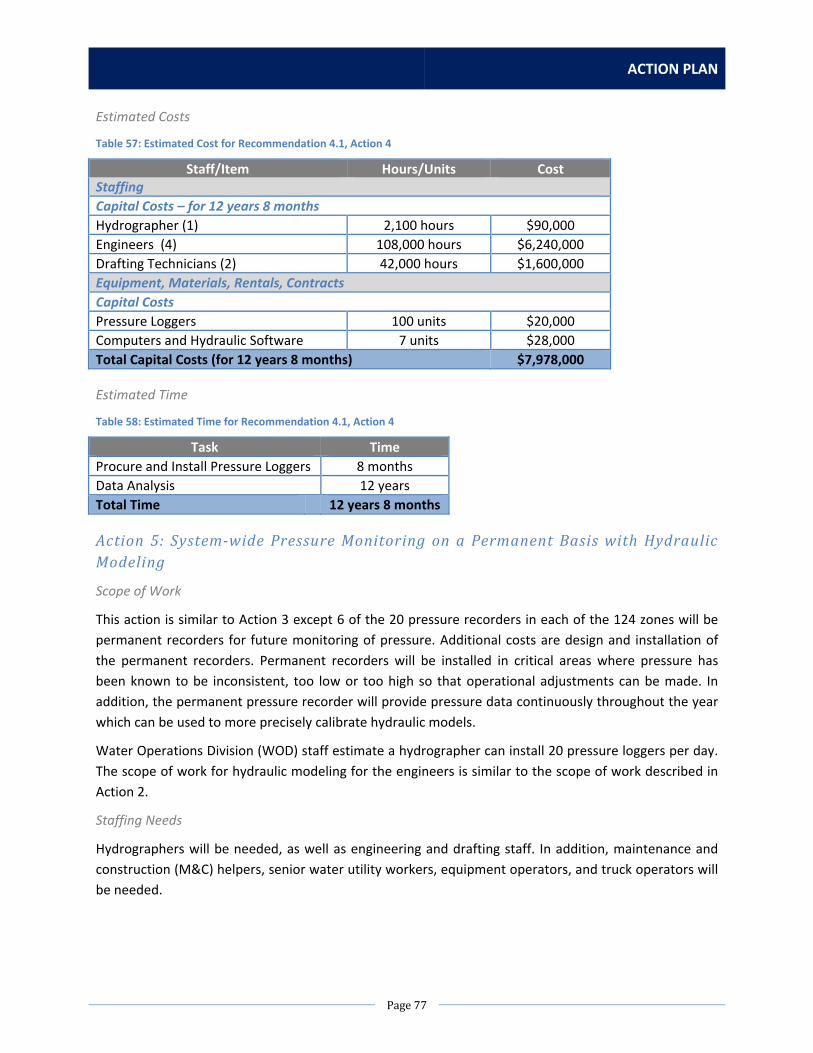
ACTION PLAN
Page77
Estimated Costs
Table 57: Estimated Cost for Recommendation 4.1, Action 4
Staff/Item Hours/Units Cost Staffing
Capital Costs – for 12 years 8 months
Hydrographer (1) 2,100 hours $90,000
Engineers (4) 108,000 hours $6,240,000
Drafting Technicians (2) 42,000 hours $1,600,000
Equipment, Materials, Rentals, Contracts
Capital Costs
Pressure Loggers 100 units $20,000
Computers and Hydraulic Software 7 units $28,000
Total Capital Costs (for 12 years 8 months) $7,978,000
Estimated Time
Table 58: Estimated Time for Recommendation 4.1, Action 4
Task Time
Procure and Install Pressure Loggers 8 months
Data Analysis 12 years
Total Time 12 years 8 months
Action5: System‐widePressureMonitoringonaPermanentBasiswithHydraulicModeling
Scope of Work
This action is similar to Action 3 except 6 of the 20 pressure recorders in each of the 124 zones will be
permanent recorders for future monitoring of pressure. Additional costs are design and installation of
the permanent recorders. Permanent recorders will be installed in critical areas where pressure has
been known to be inconsistent, too low or too high so that operational adjustments can be made. In
addition, the permanent pressure recorder will provide pressure data continuously throughout the year
which can be used to more precisely calibrate hydraulic models.
Water Operations Division (WOD) staff estimate a hydrographer can install 20 pressure loggers per day.
The scope of work for hydraulic modeling for the engineers is similar to the scope of work described in
Action 2.
Staffing Needs
Hydrographers will be needed, as well as engineering and drafting staff. In addition, maintenance and
construction (M&C) helpers, senior water utility workers, equipment operators, and truck operators will
be needed.

WATER LOSS TASK FORCE
Page78
Equipment, Materials, Rentals, and Contract Needs
100 temporary pressure loggers and 744 permanent pressure loggers will be needed, as well as 7
computer terminals and software, and other construction equipment as specified in the cost table.
Estimated Costs
Table 59: Estimated Cost for Recommendation 4.1, Action 5
Staff/Item Hours/Units Cost Staffing
Capital Costs – for 24 years 8 months
Hydrographer (1) 2,500 hours $109,000
Engineers (4) 116,500 hours $6,700,000
Drafting Technicians (2) 42,000 hours $1,600,000
Water Utility Worker (2) 50,000 hours $1,875,000
M&C Helper (2) 50,000 hours $1,600,000
Sr. Water Utility Worker (2) 50,000 hours $2,150,000
Equipment Operator (2) 6,000 hours $264,000
Truck Driver (2) 6,000 hours $174,000
Cement Finisher (2) 12,000 hours $408,000
Waterworks Mechanic (1) 12,000 hours $558,000
Electrical Mechanic (1) 12,000 hours $572,000
Electrician (1) 12,000 hours $546,000
Equipment, Materials, Rentals, Contracts
Capital Costs
Pressure Loggers (temporary) 100 units $20,000
Pressure Loggers (permanent) 744 units $26,040,000
Computers and Hydraulic Software 7 units $28,000
Dump Truck 2 units $65,000
Backhoe 2 units $270,000
Material Contract 1 unit $237,000
Total Capital Costs (for 24 years 8 months) $43,216,000
Estimated Time
Table 60: Estimated Time for Recommendation 4.1, Action 5
Task Time
Procure and Install Pressure Loggers 8 months
Data Analysis 12 years
Install Permanent Pressure Recorder 12 years
Total Time 24 years 8 months
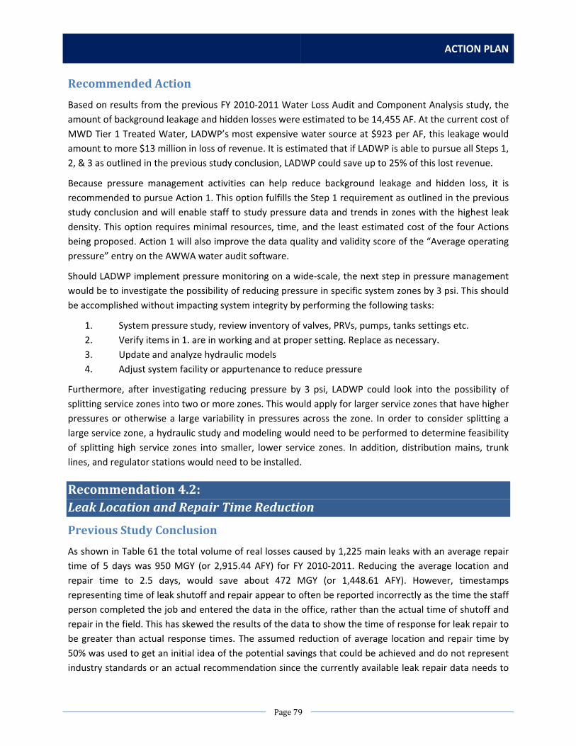
ACTION PLAN
Page79
RecommendedAction
Based on results from the previous FY 2010‐2011 Water Loss Audit and Component Analysis study, the
amount of background leakage and hidden losses were estimated to be 14,455 AF. At the current cost of
MWD Tier 1 Treated Water, LADWP’s most expensive water source at $923 per AF, this leakage would
amount to more $13 million in loss of revenue. It is estimated that if LADWP is able to pursue all Steps 1,
2, & 3 as outlined in the previous study conclusion, LADWP could save up to 25% of this lost revenue.
Because pressure management activities can help reduce background leakage and hidden loss, it is
recommended to pursue Action 1. This option fulfills the Step 1 requirement as outlined in the previous
study conclusion and will enable staff to study pressure data and trends in zones with the highest leak
density. This option requires minimal resources, time, and the least estimated cost of the four Actions
being proposed. Action 1 will also improve the data quality and validity score of the “Average operating
pressure” entry on the AWWA water audit software.
Should LADWP implement pressure monitoring on a wide‐scale, the next step in pressure management
would be to investigate the possibility of reducing pressure in specific system zones by 3 psi. This should
be accomplished without impacting system integrity by performing the following tasks:
1. System pressure study, review inventory of valves, PRVs, pumps, tanks settings etc.
2. Verify items in 1. are in working and at proper setting. Replace as necessary.
3. Update and analyze hydraulic models
4. Adjust system facility or appurtenance to reduce pressure
Furthermore, after investigating reducing pressure by 3 psi, LADWP could look into the possibility of
splitting service zones into two or more zones. This would apply for larger service zones that have higher
pressures or otherwise a large variability in pressures across the zone. In order to consider splitting a
large service zone, a hydraulic study and modeling would need to be performed to determine feasibility
of splitting high service zones into smaller, lower service zones. In addition, distribution mains, trunk
lines, and regulator stations would need to be installed.
Recommendation4.2:LeakLocationandRepairTimeReduction
PreviousStudyConclusion
As shown in Table 61 the total volume of real losses caused by 1,225 main leaks with an average repair
time of 5 days was 950 MGY (or 2,915.44 AFY) for FY 2010‐2011. Reducing the average location and
repair time to 2.5 days, would save about 472 MGY (or 1,448.61 AFY). However, timestamps
representing time of leak shutoff and repair appear to often be reported incorrectly as the time the staff
person completed the job and entered the data in the office, rather than the actual time of shutoff and
repair in the field. This has skewed the results of the data to show the time of response for leak repair to
be greater than actual response times. The assumed reduction of average location and repair time by
50% was used to get an initial idea of the potential savings that could be achieved and do not represent
industry standards or an actual recommendation since the currently available leak repair data needs to

WATER LOSS TASK FORCE
Page80
be substantially improved in terms of data quality/availability to be able to make recommendations on a
target location and repair time for mains failures.
Table 61: Summary of Economic Analysis of Improved Location and Repair Times for Main Line Failures
Using the currently available leak repair data, this analysis indicates that a reduction in average location
and repair time could represent a cost effective option for reducing real losses in LADWP’s distribution
network. Once better leak repair data is available, LADWP should update this analysis and evaluate the
necessary additional budget for reducing the average location and repair time for reported mains leaks.
As shown in Table 62 the total volume of real losses caused by 4,038 service line failures and meter leaks
with average repair times of 12 days was 264 MGY (or 810.19 AFY) for FY 2010‐2011. Reducing the
average location and repair time to 5 days, would save about 157 MGY (or 481.82 AFY). This indicates
significant potential for real loss and cost savings. The assumed reduction of average location and repair
time by 60% was used to get an initial idea of the potential savings that could be achieved and do not
represent industry standards or an actual recommendation since the currently available leak repair data
needs to be substantially improved in terms of data quality/availability to be able to make
recommendations on a target location and repair time for service line failures.
Table 62: Summary of Economic Analysis of Improved Location and Repair Times for Service Lines Failure and Meter Leaks
Using the currently available leak repair data it would indicate that a reduction in average location and
repair time for service connection and meter leaks could represent a cost effective option for reducing
real losses in LADWP’s distribution network. Once better leak repair data is available, LADWP should
update this analysis and evaluate the necessary additional budget for reducing the average location and
repair time for service connection and meter leaks.
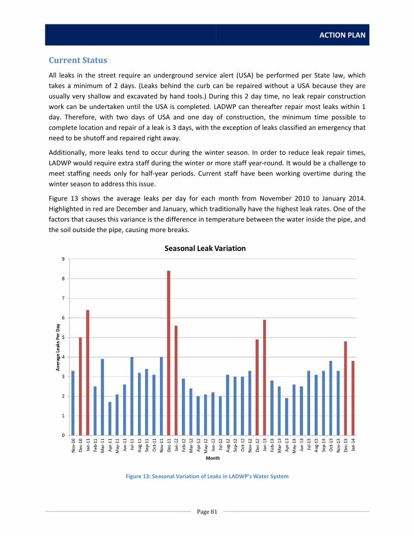
ACTION PLAN
Page81
CurrentStatus
All leaks in the street require an underground service alert (USA) be performed per State law, which
takes a minimum of 2 days. (Leaks behind the curb can be repaired without a USA because they are
usually very shallow and excavated by hand tools.) During this 2 day time, no leak repair construction
work can be undertaken until the USA is completed. LADWP can thereafter repair most leaks within 1
day. Therefore, with two days of USA and one day of construction, the minimum time possible to
complete location and repair of a leak is 3 days, with the exception of leaks classified an emergency that
need to be shutoff and repaired right away.
Additionally, more leaks tend to occur during the winter season. In order to reduce leak repair times,
LADWP would require extra staff during the winter or more staff year‐round. It would be a challenge to
meet staffing needs only for half‐year periods. Current staff have been working overtime during the
winter season to address this issue.
Figure 13 shows the average leaks per day for each month from November 2010 to January 2014.
Highlighted in red are December and January, which traditionally have the highest leak rates. One of the
factors that causes this variance is the difference in temperature between the water inside the pipe, and
the soil outside the pipe, causing more breaks.
Figure 13: Seasonal Variation of Leaks in LADWP’s Water System

WATER LOSS TASK FORCE
Page82
The new e‐Respond project will convert the current leak datasets, housed in several different databases,
into one, easy to use leak information system. The project is in progress. e‐Respond, along with staff
training, will also help to address inconsistences in how LADWP staff fill out timestamps for leak location
and repair times, with a goal of providing a more accurate picture of water volumes lost due to leaks.
Additionally, WDD Meter and Service Section has recently hired six new full‐time employees. These
employees have assisted in addressing and repairing meter leaks. Due to the increased number of staff
dedicated to meter leak repairs, the response time for meter leak repairs has already decreased to an
average of approximately five days. Furthermore, WDD has an ongoing large valve replacement program
that will help crews shut off leaks in a more efficient manner.
ListofActions
NoAction
Summary of Impact
LADWP will continue to respond to leak reports and perform repairs at about the same time as is
performed currently. There will be no improvement to response time for leak location and repair.
Action1:AddInternalStafftoDecreaseLeakResponseTimes
Scope of Work
Add two LADWP leak crews for the off‐hour shifts (PM and AM shifts) for all five districts to assist the
leak sections in the districts. This will help decrease the leak response time for all types of leaks. These
additional staff could also assist with other work to help reduce leaks during non‐peak seasons, such as
helping with leak survey and anode installations to decrease pipe corrosion.
Staffing Needs
2 Sr. Water Utility Workers would be needed to pair up with 2 Water Utility Workers. These personnel
would form 2 two‐man leak repair crews.
Equipment, Materials, Rentals, and Contract Needs
2 Maintenance and Construction Trucks would be needed along with 2 two axle Dump Trucks and 2 Tow
Compressors.

ACTION PLAN
Page83
Estimated Costs
Table 63: Estimated Cost for Recommendation 4.2, Action 1
Staff/Item Hours/Units Cost Staffing
Operations & Maintenance Costs – per year
Sr. Water Utility Worker (2) 2,080 hours $92,000
Water Utility Worker (2) 2,080 hours $80,000
Equipment, Materials, Rentals, Contracts
Capital Costs
Maintenance and Construction Truck (2) 2,080 hours $41,000
2 Axle Dump Truck (2) 2,080 hours $27,000
Tow Compressor (2) 2,080 hours $4,000
Total Capital Costs (equipment only) $72,000
Total Operations & Maintenance Costs (per year) $172,000
Estimated Time
Table 64: Estimated Time for Recommendation 4.2, Action 1
Task Time
Hiring 15 months
Vehicle and Equipment Procurement 3 months
Leak Repair and Other Support Work Ongoing
Total Time 18 months + ongoing
Action 2: Hire a Contractor to Help Fix Leaks and Decrease Response TimesDuringtheWinterMonths
Scope of Work
Hire a contractor that could have up to 2 crews available, on 48 hours’ notice, to repair small main and
service leaks.
Staffing Needs
One Sr. Water Utility Workers would be needed to inspect the contractors work.
Equipment, Materials, Rentals, and Contract Needs
One Pickup Truck would be needed.

WATER LOSS TASK FORCE
Page84
Estimated Costs
Table 65: Estimated Cost for Recommendation 4.2, Action 2
Staff/Item Hours/Units Cost Staffing
Operations & Maintenance Costs – per year
Sr. Water Utility Worker (1) 1,040 hours $46,000
Equipment, Materials, Rentals, Contracts
Operations & Maintenance Costs – per year
Leak Repair Crew Contract 1 unit $700,000
Pickup Truck Rentals (1) 1,040 hours $6,000
Total Operations & Maintenance Costs (per year) $752,000
Estimated Time
Table 66: Estimated Time for Recommendation 4.2, Action 2
Task Time
Procuring Contract 18 months
Vehicle Procurement 3 months
Leak Repair Work Ongoing
Total Time 18 months + ongoing
RecommendedAction
Based on results from the previous FY 2010‐2011 Water Loss Audit and Component Analysis study, the
amount of reported leakage was estimated to be 4,326 AF. At the current cost of MWD Tier 1 Treated
Water, LADWP’s most expensive water source at $923 per AF, this leakage would amount to almost $4
million in loss of revenue. However, due to the data quality issues with the timestamps used to estimate
the reported leakage, that volume and subsequent loss in revenue is likely over‐estimated. Furthermore,
pursuing either Actions 1 or 2 will not eliminate the entire lost revenue, but could reduce the losses by
an estimate of up to 25% if the run time of the leaks in the winter months is reduced by almost half.
Therefore, it is recommended to first re‐evaluate average response times to leak repairs based on
improved data that will be received through the e‐Respond system, as described in Recommendation
2.4. Proactively, however, it is also recommended to consider pursuing Action 1 as this provides multiple
benefits in meeting the goal of reducing leaks through lower response times and also through leak
survey assistance and additional anode installations.

ACTION PLAN
Page85
Recommendation4.3:ActiveLeakDetection
PreviousStudyConclusion
Analyses indicate that given the relatively high monetary value of real losses, it is economically
beneficial to LADWP to periodically survey the distribution network for unreported leaks. Considering
this, the FY2010‐11 Water Loss Audit and Component Analysis Study recommended that LADWP targets
surveying about 10% to 15% of the distribution network per year for the next five years using in‐house
resources and carefully documenting the results and findings to inform LADWP’s future proactive leak
detection strategy. Since LADWP is considering trials of Advanced Metering Infrastructure (AMI), the
Study recommended that for the service zones with AMI a water loss mass balance is calculated on a
regular basis to identify service zones with higher levels of leakage that should be targeted for proactive
leak detection. The three service zones used for the District Metered Analysis in the previous Water Loss
Audit and Component Analysis study should be considered as candidates for trial AMI installations.
CurrentStatus
LADWP has participated in several pilot studies in recent years to evaluate the performance and
accuracy of the leak detection technology available in the industry. In addition, Water Distribution
Division (WDD) and Asset Management Group (AMG) are engaging and meeting with several firms to
learn about the available products, methods of leak detection, performance and reliability. This effort is
on‐going as the technology is evolving and improving. The following list summarizes some of the
different technologies WDD and AMG have been evaluating:
Leak Detection Acoustic Sensors
Hydraulic & Leak Modeling and Data Management
Pipe Assessment and Rehabilitation
Broadband Electromagnetic Technology
Pressure Transient Detection and Reporting
Pressure and Flow Monitoring
Pilot studies on these technologies are in the planning stages and proceeding timely. AMG and WDD are
collaborating and sharing resources to determine the most optimal locations for these pilot studies,
targeting the most vulnerable areas in the City. The results of these pilot studies will help LADWP
identify and select the appropriate products for permanent implementation.
ListofActions
NoAction
Summary of Impact
For a No Action option, the amount of unreported leakage remains unchanged and no water savings are
realized through proactive leak management. By not installing an active leak detection system, volume
of unreported leakage would continue to accumulate in the system. This action would not improve the

WATER LOSS TASK FORCE
Page86
system’s efficiency and would not be a cost savings to the ratepayers. LADWP has initiated several pilot
studies for leak detection devices and will continue to plan partial implementation.
Action 1: Deploy Acoustic Leak Detection Crews to Survey 10% of the EntireSystemPerYear
Scope of Work
LADWP personnel would survey at least 10% of the system’s mainline every year, which represents
approximately 720 miles. It is estimated that one leak detection crew could survey approximately 10%
of the system’s mainlines, including services, in a year.
Staffing Needs
A leak detection crew would consist of 1 Senior Water Utility Worker and 1 Water Utility Worker.
Equipment, Materials, Rentals, and Contract Needs
1 Pickup truck is needed, as well as leak detection equipment.
Estimated Costs
Table 67: Estimated Cost for Recommendation 4.3, Action 1
Staff/Item Hours/Units Cost Staffing
Operations & Maintenance Costs – per year
Sr. Water Utility Worker (1) 2,080 hours $92,000
Water Utility Worker (1) 2,080 hours $80,000
Equipment, Materials, Rentals, Contracts
Operations & Maintenance Costs – per year
Pickup Truck Rental (1) 2,080 hours $11,000
Capital Costs
Leak Detection Equipment 1 unit $3,000
Total Capital Costs (equipment only) $3,000
Total Operations & Maintenance Costs (per year) $183,000
Staffing costs could be eliminated if staff are hired under Recommendation 4.2, Action 1 that can help
perform leak survey in addition to assisting with leak repair work.
Estimated Time
Table 68: Estimated Time for Recommendation 4.3, Action 1
Task Time
Hiring (if needed) 15 months
Vehicle and Equipment Procurement 3 months
Leak Survey Ongoing
Total Time 18 months + ongoing

ACTION PLAN
Page87
Action 2: DeployAcoustic LeakDetection Crews to Survey Specific System ZoneswithHighestLeakDensitiesand/orCriticalAreas
Scope of Work
The six highest leak rate areas identified in Figure 11 total 1,224 miles of piping, which is a little less than
17% of the total system mainline. Surveying all six areas annually would require the services of 2 leak
detection crews. These crews could supplement leak repair crews when they were not actively surveying
mainline.
Staffing Needs
Two leak detection crews are needed, consisting of one Sr. Water Utility Worker and one Water Utility
Worker each.
Equipment, Materials, Rentals, and Contract Needs
Two Pickup trucks are needed, as well as leak detection equipment.
Estimated Costs
Table 69: Estimated Cost for Recommendation 4.3, Action 2
Staff/Item Hours/Units Cost Staffing
Operations & Maintenance Costs – per year
Sr. Water Utility Worker (2) 3,640 hours $160,000
Water Utility Workers (2) 3,640 hours $141,000
Equipment, Materials, Rentals, Contracts
Operations & Maintenance Costs – per year
Pickup Truck Rentals (2) 3,640 hours $20,000
Capital Costs
Leak Detection Equipment 2 units $6,000
Total Capital Costs (equipment only) $6,000
Total Operations & Maintenance Costs (per year) $321,000
Staffing costs could be eliminated if staff are hired under Recommendation 4.2, Action 1 that can help
perform leak survey in addition to assisting with leak repair work.
Estimated Time
Table 70: Estimated Time for Recommendation 4.3, Action 2
Task Time
Hiring (if needed) 15 months
Vehicle and Equipment Procurement 3 months
Leak Survey Ongoing
Total Time 18 months + ongoing

WATER LOSS TASK FORCE
Page88
Action 3: Install Acoustic Leak Monitoring Sensors in Areas with Highest LeakDensities
Scope of Work
The leak data that LADWP has been collecting are available on GIS and can be graphed for analysis.
Several geographical areas with the highest leak densities have been identified in the Central, Western
and Harbor districts. Piping in these areas was installed prior to 1940 and these are among the oldest
pipes in the City. Some of these areas also have the highest concentrations of the oldest pipes in service
and, hence, are more prone to leakage.
LADWP is evaluating several leak detection products to perform pilot projects and determine its
performance. An acoustic leak monitoring system will be selected and installed in the high leak areas,
starting with the highest leak locations. Currently, there are leak detection devices under evaluation
that can be installed on the piping system without interrupting the pipe operation. Each acoustical
logger has a maximum range of 750 feet in each direction or 1,500 feet apart.
The two highest leak rate areas are identified in Figure 11 with 21 miles and 58 miles of piping, or about
1% of the total mainlines in the system. Based on this piping mileage with 1,300‐foot spacing for the
loggers, approximately 90 devices will be required to cover a 21‐mile pipe length and 240 devices for a
58‐mile coverage.
Staffing Needs
One engineering associate will be needed to monitor the devices, collect data, and perform evaluations.
An additional two‐person crew is needed to install the leak detection devices.
Equipment, Materials, Rentals, and Contract Needs
330 acoustical logger devices and required telemetry for data transmission and evaluation are needed,
including the Cloud data access and device status monitoring.
A contract agreement is needed with the vendor to rent or purchase the devices, to maintain or replace
the power supply package, and to have a service agreement for the data access and monitoring for two‐
year period.

ACTION PLAN
Page89
Estimated Costs
Table 71: Estimated Cost for Recommendation 4.3, Action 3
Staff/Item Hours/Units Cost Staffing
Capital Costs – for 2 years 10 months
Engineering Associate (1) 3,360 hours $259,000
Crew Member (2) 840 hours $50,000
Equipment, Materials, Rentals, Contracts
Capital Costs
Acoustical logger devices 330 units $776,000
Telemetry (collectors, repeaters) 7 units $56,000
Service Agreement – Cloud access 1 unit $2,000
Total Capital Costs (for 2 years 10 months) $1,143,000
Estimated Time
Table 72: Estimated Time for Recommendation 4.3, Action 3
Task Time
Procure and Install Loggers 9 months
Install Telemetry 1 month
Cloud Monitoring and Data Analysis 2 years
Total Time 2 years 10 months
Action4:InstallAcousticLeakMonitoring SensorsSystem‐wide
Scope of Work
This action is an extension of Action 3 and is applied to the entire water system pipeline network. The
current system has over 7,200 miles of piping which includes over 6,700 miles of mainlines (20‐inch
diameter and less) and over 500 miles of trunk lines (more than 20‐inch diameter). Based on this
mileage length of piping, which is over 38 million feet of piping, approximately 26,000 logging devices
are required.
Staffing Needs
Five engineering associates will be needed to monitor the devices, collect data, and perform
evaluations. Five additional two‐person crews are needed to install the leak detection devices.
Equipment, Materials, Rentals, and Contract Needs
26,000 acoustical logger devices and required telemetry for data transmission and evaluation are
needed, including the Cloud data access and device status monitoring.
A contract agreement is needed with the vendor to rent or purchase the devices, to maintain or replace
the power supply package, and to have a service agreement for the data access and monitoring for a
two‐year period.

WATER LOSS TASK FORCE
Page90
Estimated Costs
Table 73: Estimated Cost for Recommendation 4.3, Action 4
Staff/Item Hours/Units Cost Staffing
Capital Costs – for 4 years
Engineering Associate (5) 16,800 hours $1,294,000
Crew Member (10) 11,200 hours $672,000
Equipment, Materials, Rentals, Contracts
Capital Costs
Acoustical logger devices 26,000 units $28,080,000
Telemetry (collectors, repeaters) 260 units $1,300,000
Service Agreement – Cloud access 1 unit $24,000
Total Capital Costs (for 4 years) $31,370,000
Estimated Time
Table 74: Estimated Time for Recommendation 4.3, Action 4
Task Time
Procure Loggers 1 year
Install Loggers and Telemetry 1 year
Cloud Monitoring and Data Analysis 2 years
Total Time 4 years
RecommendedAction
Based on results from the previous FY 2010‐2011 Water Loss Audit and Component Analysis study, the
amount of hidden losses were estimated to be 2,434 AF. At the current cost of MWD Tier 1 Treated
Water, LADWP’s most expensive water source at $923 per AF, this leakage would amount to over $2
million in loss of revenue. It is estimated that Actions 1 and 3 can help recover 11% of this lost revenue.
Action 1 will allow LADWP to perform annual leak surveying of 10% of the distribution system. This will
provide more information about hidden losses on a system‐wide basis. Action 3 will allow LADWP to
collect more information on potential hidden losses an automated basis in the areas which have shown
the highest number of reported leaks in recent years. The cost of Action 3 is roughly equivalent to the
cost of Action 2 on an annual basis. While Action 2 will cover more mileage, Action 3 will provide
monitoring on a continuous, real‐time basis, which would be of greater benefit to the areas showing the
highest levels of reported leakage. Therefore, it is recommended to pursue Actions 1 and 3.
In addition to the recommended actions, LADWP should consider composing a group responsible for
evaluating new leak detection technologies. This would include following the market for new products,
understanding the analysis and functions, the limitations, and most effective applications. When
technologies are determined to be worth testing, pilot projects and demonstration can be done to
determine practical application and cost for implementation.
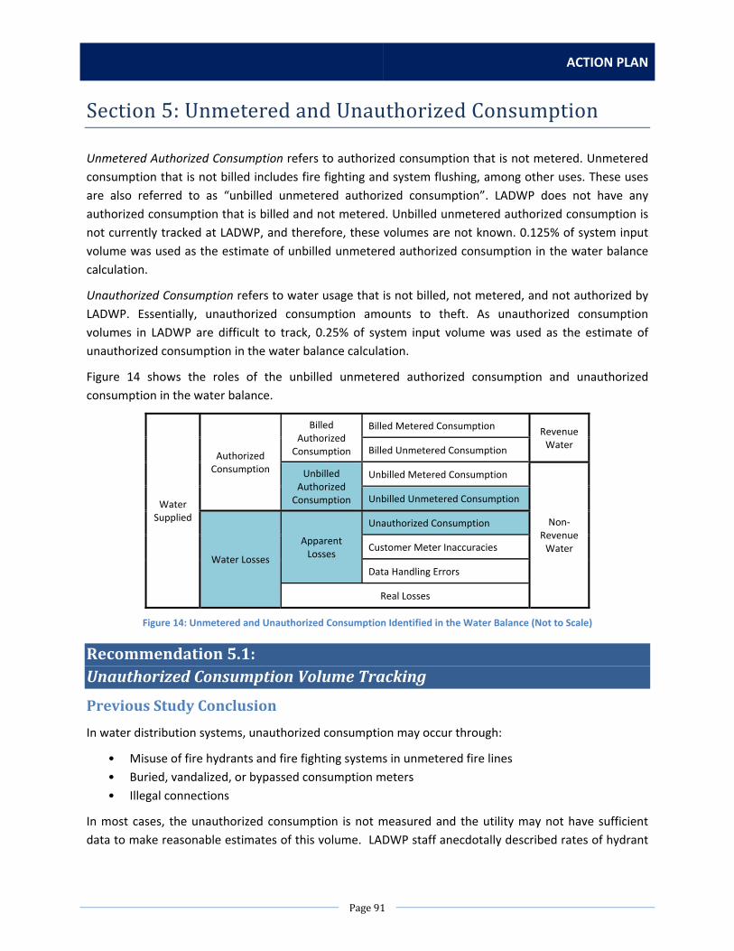
ACTION PLAN
Page91
Section5:UnmeteredandUnauthorizedConsumption
Unmetered Authorized Consumption refers to authorized consumption that is not metered. Unmetered
consumption that is not billed includes fire fighting and system flushing, among other uses. These uses
are also referred to as “unbilled unmetered authorized consumption”. LADWP does not have any
authorized consumption that is billed and not metered. Unbilled unmetered authorized consumption is
not currently tracked at LADWP, and therefore, these volumes are not known. 0.125% of system input
volume was used as the estimate of unbilled unmetered authorized consumption in the water balance
calculation.
Unauthorized Consumption refers to water usage that is not billed, not metered, and not authorized by
LADWP. Essentially, unauthorized consumption amounts to theft. As unauthorized consumption
volumes in LADWP are difficult to track, 0.25% of system input volume was used as the estimate of
unauthorized consumption in the water balance calculation.
Figure 14 shows the roles of the unbilled unmetered authorized consumption and unauthorized
consumption in the water balance.
Water Supplied
Authorized Consumption
Billed Authorized Consumption
Billed Metered Consumption Revenue Water
Billed Unmetered Consumption
Unbilled Authorized Consumption
Unbilled Metered Consumption
Non‐Revenue Water
Unbilled Unmetered Consumption
Water Losses
Apparent Losses
Unauthorized Consumption
Customer Meter Inaccuracies
Data Handling Errors
Real Losses
Figure 14: Unmetered and Unauthorized Consumption Identified in the Water Balance (Not to Scale)
Recommendation5.1:UnauthorizedConsumptionVolumeTracking
PreviousStudyConclusion
In water distribution systems, unauthorized consumption may occur through:
• Misuse of fire hydrants and fire fighting systems in unmetered fire lines
• Buried, vandalized, or bypassed consumption meters
• Illegal connections
In most cases, the unauthorized consumption is not measured and the utility may not have sufficient
data to make reasonable estimates of this volume. LADWP staff anecdotally described rates of hydrant

WATER LOSS TASK FORCE
Page92
misuse and theft off fire connections as quite high (though no specific volumes could be provided).
Without volume estimations, the AWWA M36 Manual recommends assuming a default value of 0.25%
of the water supplied as the volume of unauthorized consumption. For the FY 2010‐2011 LADWP water
audit, the estimated unauthorized consumption volume was 439.06 MG (1,347.43 AF).
CurrentStatus
LADWP is aware of the fact that there are many different ways that water is being consumed without
authorization. It may be residential or commercial theft, smashed or defective meters, cross connections
between domestic and fire services, illegal fire hydrant connections, etc.
When accounts are identified as having a possible problem with the service, the Customer Service
Division (CSD) Field Investigation (FI) and Revenue Security Unit (RSU) will attempt to identify the nature
of loss: faulty equipment or intentional theft and tampering.
Following investigation, a corrected bill is issued using one of the following methods:
estimated based on prior history on the account
observation field checks of property, how services are being used, what equipment is installed
developed using a daily rate of use on the new meter once installed
on a negotiated basis with the customer
The billing instructions do not quantify the dollar amount but only the HCF to be billed. There is no
formal way to capture this number at this time. FI generates Field Activities (F/A’s) to Water Distribution
Division (WDD) Meter and Service Section to have meters replaced when damaged or defective (stuck).
When RSU is involved, the accounts are referred from many areas (CSD reports and field operations,
WDD Meter and Service Section, Security Services Division – Office of Special Investigations, email from
reports filed at www.ladwp.com, LAFD, LADBS, LAPD, etc.). These accounts are suspected of engaging in
theft or tampering with the services. The accounts are reviewed and investigated. Once identified as
unauthorized consumption, RSU takes appropriate action to stop the use including issuing orders to
WDD Meter and Service Section for removing or installing meters, disconnecting services. RSU attempts
to determine the losses and render an appropriate one time bill for both the revenue loss as well as
expenses associated with the cost to correct the issue. For illegal fire hydrant connections, RSU assesses
a daily temporary meter fee unless there is a way to define the amount of water lost.
WDD Meter and Service Section currently only reads fire service meters when the meter vault is checked
for maintenance. There are currently no scheduled actual readings and no mechanism to bill fire
services. Generally, 10 HCF is allowed annually for fire system testing purposes. Usage registered on a
fire service meter beyond that amount would be questionable.

ACTION PLAN
Page93
ListofActions
NoAction
Summary of Impact
The impacts of not tracking unauthorized consumption are two‐fold:
1. The uncertainty in the unauthorized consumption value adds to the uncertainty of the total
apparent loss volume (an accounting challenge that affects the real loss determination)
2. There is a need to measure the illegal activity/volume "lost" to theft in order to reduce it.
By only reading the detector check meters on fire services during periodic vault inspections, the
potential water losses are likely to go undetected for several years. Additionally the detector check
meter only records a portion of the water based on the rate of flow. Not reading the fire service meters
on a regularly scheduled (monthly) basis means that there would still be greater volumes of undetected
water that will continue to remain unknown. Therefore, uncertainties and errors will continue to be
introduced into the water loss calculation.
Action 1: Initiate an Automated Meter Reading (AMR) Program for Fire ServiceMeters
Scope of Work
Install AMR infrastructure in the form of remote read radio frequency (RF) meters on all the fire
services. Then change the read responsibility as these meters are installed from WDD Meter and Service
to CSD Meter Reading. This would allow meter readings on a monthly basis to facilitate a quicker
response to fire services showing recorded use. Out of 19,079 total fire services, 17,524 fire services still
need to have RF meters installed. It is proposed to start with RF installations on around 1,000 fire
services to pilot the program, and re‐evaluate implementation on a full‐scale basis at a later time.
RF units will need to be tested after installation and compared with manual reads to ensure they are
working properly. In addition, meter registers should be reset to zero after installation to avoid
generating a bill. WDD Meter & Service should manually read the meter upon RF installation to confirm
starting read.
Meter readers will only be able to read flow that goes through the bypass meter. There is no meter on
the detector check main line. So the reading can indicate flow going through the detector check, but will
not provide an accurate measurement of the volume of water passing through the fire service main line.
Staffing Needs
WDD Meter and Service staff needed include 1 additional two man crew (1 hour each per detector
check), 1 specialist, and 1 service worker. Customer Services will need increased staffing both in office
and field functions. Account Services would need additional personnel to ensure proper coding for
reading and billing services. Information Technology Services (ITS) Division will need to provide
necessary resources for programming the fire services to be allowed to be read properly, configured and
billed on CCB. There will also be requirements to develop tracking reports, exception reports, develop

WATER LOSS TASK FORCE
Page94
flags to alert and generate investigation requests to appropriate groups (WDD Meter and Service, FI, or
RSU). CSD field operations will require additional personnel in meter reading, FI, and RSU to respond to
regular reading, or investigating exceptions reported.
A Commercial Field Representative is needed to perform route design to incorporate fire service meters
into existing routes. A Customer Service Representative is needed to assist with billing uses deemed
over the allotted amount. A Programmer Analyst is needed to send and receive service points to and
from RouteSmart and look at meter read upload and download processes.
All costs detailed in this action are based on a 2 ½ year period. Some additional continuing costs will
exist after the initial two and one half year period for Customer Service Division as well as WDD Meter
and Service to inspect, maintain and investigate fire services which will continue generate reports to be
checked out.
Equipment, Materials, Rentals, and Contract Needs
Approximately 825 5/8 x 3/4 bypass meters with RF for 8” and smaller detector checks and 175 1 ‐1/2”
bypass meters with RF for 10” detector checks are needed to replace the current fire service meters.
Also needed are 4 vehicles (1 for WDD Meter and Service, 1 for CSD Meter Reading, and 2 for FI and
RSU), computers, handheld devices, and other tools.
Estimated Costs
Table 75: Estimated Cost for Recommendation 5.1, Action 1
Staff/Item Hours/Units Cost Staffing
Capital Costs – for 6 months
WDD Meter and Service Staff (2) 7,100 hours $413,000
Commercial Field Representative (1) 200 hours $8,000
Programmer Analyst (1) 500 hours $27,000
Operations & Maintenance Costs – per year
Meter Readers (1) 3,780 hours $175,000
Field Investigators (1) 1,890 hours $208,000
Revenue Security Unit Investigator (1) 756 hours $223,000
Customer Service Representatives (1) 5,000 hours $160,000
Equipment, Materials, Rentals, Contracts
Capital Costs
Vehicles 4 units $112,000
5/8”x ¾” Bypass Meters with RF 825 units $106,000
1”x 1½” Bypass Meters with RF 175 units $49,000
Computers, Handheld Devices, Tools 2 units $8,000
Total Capital Costs (for 6 months) $723,000
Total Operations & Maintenance Costs (per year) $766,000

ACTION PLAN
Page95
Estimated Time
Table 76: Estimated Time for Recommendation 5.1, Action 1
Task Time
Installation of RF Meters 6 months
Route Design and Changes 2 months
Coding and Programming 3 months
Meter Reading and Field Investigations
Ongoing
Total Time 6 months + ongoing
Some phases of the timeline overlap in timeframe.
Action 2: Initiate an Advanced Metering Infrastructure (AMI) Program for FireServiceMeters
Scope of Work
Install advanced metering infrastructure (AMI), a.k.a. “smart meters”, on the bypass lines of fire service
meters to track usage. The smart meters will track usage on an hourly basis and show patterns in usage
that could determine potential theft. Since there are around 19,000 fire service meters in LADWP’s
service area, a pilot installation of around 1,000 smart meters is recommended to begin with to evaluate
the program and plan for future needs. A system for transmitting and downloading the data to a central
server will also be needed. There will also be requirements to develop tracking reports, exception
reports, develop flags to alert and generate investigation requests to appropriate groups (WDD Meter
and Service, FI, or RSU). CSD field operations will require additional personnel in meter reading, FI, and
RSU to respond to regular reading, or investigating exceptions reported.
LADWP is currently doing several pilot AMI programs. An evaluation of the AMI data and the reliability
of the communications platform will be completed before implementing the installation of smart meters
on a full‐scale basis.
Staffing Needs
Five water service workers will be needed to install 1,000 smart meters in one year. A programmer
analyst and database architect may be needed to program an alert system in CCB that would alert field
investigations of above‐average usage based on reading recorded by the smart meters. It is estimated
that four field investigators, one revenue security investigator, and two customer service
representatives will be needed to investigate flagged abnormal uses on fire service meters and generate
bills for those accounts identified as over their allotment.
Equipment, Materials, Rentals, and Contract Needs
1,000 smart meter units will be needed. Five vehicles will also be needed.

WATER LOSS TASK FORCE
Page96
Estimated Costs
Table 77: Estimated Cost for Recommendation 5.1, Action 2
Staff/Item Hours/Units Cost Staffing
Capital Costs – for 1 year
Water Service Workers (5) 1,040 hours $39,000
Database Architect (1) 500 hours $32,000
Programmer Analyst (1) 500 hours $27,000
Operations & Maintenance Costs – per year
Field Investigators (1) 1,890 hours $208,000
Revenue Security Unit Investigator (1) 756 hours $223,000
Customer Service Representatives (1) 5,000 hours $160,000
Equipment, Materials, Rentals, Contracts
Capital Costs
Vehicles 5 units $140,000
Smart Meter Units 1,000 units $275,000
Total Capital Costs (for 1 year) $513,000
Total Operations & Maintenance Costs (per year) $591,000
Estimated Time
Table 78: Estimated Time for Recommendation 5.1, Action 2
Task Time
Installation of Smart Meters 9 months
Coding and Programming 3 months
Field Investigations Ongoing
Total Time 1 year + ongoing
Action 3: Research Other Areas of Potential Unauthorized Consumption andRecommendPolicyChanges
Scope of Work
Staff from Water Distribution Division (WDD) and Water Resources Division (WRD) will conduct research
and initial investigation of other potential types of unauthorized consumption not identified by the
previous Water Loss Audit and Component Analysis study and not currently known by Customer
Services Division or Security Services Division. This could include unauthorized fill‐ups at fire hydrants by
private companies or other individuals, or unauthorized disconnections of services. WDD and WRD staff
will also recommend an ordinance or policy change to include measures for theft prevention, such as
requiring meters on all trucks that fill up at hydrants.
Staffing Needs
One engineering associate and one water utility superintendent would be needed for the initial phase of
research and investigation. Other staff needs would be determined at later date as needed.

ACTION PLAN
Page97
Equipment, Materials, Rentals, and Contract Needs
No additional equipment, materials, rentals, and contract needs are needed during the initial stage.
Estimated Costs
Table 79: Estimated Cost for Recommendation 5.1, Action 3
Staff/Item Hours/Units Cost Staffing
Capital Costs – 2 months
Engineering Associate (1) 200 hours $10,000
Water Utility Superintendent (1) 200 hours $15,000
Equipment, Materials, Rentals, Contracts
N/A N/A N/A
Total Capital Costs (for 2 months) $25,000
Estimated Time
Table 80: Estimated Time for Recommendation 5.1, Action 3
Task Time
Research and Investigation 1 month
Draft Suggested Policy Changes 1 month
Total Time 2 months
RecommendedAction
Based on results from the previous FY 2010‐2011 Water Loss Audit and Component Analysis study, the
amount of unauthorized consumption in LADWP’s system was estimated to be 1,347 AF. At the current
cost of MWD Tier 1 Treated Water, LADWP’s most expensive water source at $923 per AF, this theft
would amount to over $1 million in loss of revenue. However, because this estimate is based on AWWA
national standards and not on LADWP area‐specific volumes of theft, which are currently not fully
known, this estimate could be higher or lower than the actual value. Additionally, improving the
estimates of unauthorized consumption volumes will improve subsequent estimates of apparent and
real loss volumes in LADWP’s system. This will improve the data quality and validity score of the
“Unauthorized consumption” entry on the AWWA water audit software.
Therefore, it is recommended to pursue a combination of Actions 1 and 2, pilot AMI/AMR installation, to
help provide more information on theft occurring in LADWP’s system through fire service meters. This
was a critical area identified for further investigation after the completion of the District Metered Area
analysis in the previous FY 2010‐2011 Water Loss Audit and Component Analysis study. Should Actions 1
and 2 prove successful, it is recommended to deploy AMI/AMR on a system‐wide scale for all existing
fire service meters and to include a design standard change that requires new fire services have
AMI/AMR installed.
Furthermore, it is recommended to pursue Action 3 to continue research and investigate other sources
of theft not known or identified, and to be able to suggest policy changes to help prevent such theft.

WATER LOSS TASK FORCE
Page98
Recommendation5.2:AuthorizedUnmeteredUsesTracking
PreviousStudyConclusion
“Unbilled Unmetered Authorized Consumption” is the volume of water estimated as taken from the
system unmetered and for which no bill is issued. For LADWP, uses of unbilled unmetered authorized
consumption include fire fighting and mains flushing. However, records of estimates for these volumes
were unavailable for the audit period. LADWP staff reports that flushing was kept at a minimum during
the audit period due to mandatory conservation measures.
For the water balance, an estimate of 0.125% of the water supplied was used for unbilled unmetered
authorized consumption. This equates to 219.47 MG (673.53 AF).
CurrentStatus
Water Main Flushing
Water main flushing may be done as the result of field inspection of water quality complaints. In recent
years, this may have been 2‐5 times per year, which is very seldom. However, most regular flushing
operations have been suspended due to current drought conditions.
Sewer Flushing
Sewer flushing is performed daily by the Los Angeles Bureau of Sanitation (LASAN) to remove blockages
so that wastewater in sewer pipes can be conveyed to one of the City's four treatment/water
reclamation plants for treatment, reuse or discharge. This flushing activity typically uses potable water.
LASAN estimates that on a daily basis, 40 wastewater collection crews are deployed to flush sewer pipes
to comply with the goals initiated by Collection Systems Settlement Agreement. Each crew uses around
15,000 gallons of water per truck and can use up to 4 loads per truck per day. After the initial fill at a
maintenance yard, all subsequent fills appear to be unmetered. In total, this amounts to 2,400,000
gallons used for flushing activities on a daily basis, or 624,000,000 gallons used on an annual basis. It is
apparent that 75% of this use is unmetered. In FY 2013‐2014, LASAN reports that 128,000 sewer pipes
were flushed with potable water.
LASAN is currently working with LADWP’s Recycled Water Planning Group to locate two new recycled
water hydrants at its North Central Yard. These recycled water hydrants could be used for flushing
activities and would reduce potable water used during sewer pipe flushing.
Street Sweeping Uses
Street sweeping water uses are not typically monitored and recorded. Per conversations with the Los
Angeles Bureau of Street Services (LABSS), a street sweeping truck typically carries 325 gallons and is
refilled three times a day. LABSS typically operates 65‐75 sweepers daily. Based on this information, it is
estimated that LABSS uses 17,000,000 gallons per year in street sweeping operations. Of that total,
approximately 325,851 gallons per year of the water used in street sweeping operations is recycled
water. This amounts to about 2% of the total street sweeping water usage.

ACTION PLAN
Page99
Fire Fighting Uses
Water Operations Division (WOD) provides a rough estimate of water used to fight a specific fire upon
special request. This estimate is calculated by considering the drawdown of nearby reservoirs and/or
tanks that feed the system. Water Distribution Division (WDD), also provides estimates of water used to
fight a specific fire upon request. Typically, WDD would take a look at the service zone and run a
hydraulic analysis to determine the flow rate from the fire hydrant. WDD also looks at the hydrants in
the area, and gets input from LAFD on which ones they used, and for approximately how long.
WOD, WDD, and Water Resources Division (WRD) staff have coordinated with Los Angeles Fire
Department (LAFD) training coordinators to provide a suitable location for fire testing operations that
does not result in water lost to the storm drain system. This was prompted by the current drought and
the need for water conservation. WDD Meter and Service Section is currently in communications with
LAFD to provide an appropriately‐sized temporary meter that can be attached either to the hydrant or
fire hose. The metered flows will provide a rough estimate of flows used by LAFD to fight fires. This
could be a first step in refining estimates of fire fighting uses in LADWP’s service area.
ListofActions
NoAction
Summary of Impact
LADWP would continue to use the AWWA default value for unbilled unmetered authorized volumes. The
validity score for this item would remain low.
Action1:ProvideanEstimateonVolumeofWaterUsed forWaterMain Flushing
Scope of Work
Water Operations Division hydrographers could use piezometers to monitor static pressures in the
hydrants used for flushing and calculate an estimate of volume used. Due to staffing constraints, this
type of monitoring could be performed on certain percentage of total flushing activities and the data
extrapolated to provide an estimate of all water volumes used for flushing. The cost estimate assumes
the hydrographer will spend 6 months out of the year working on estimating flushing volumes.
Due to the current drought, system flushing activities have been severely reduced to only those
activities deemed necessary to remain in compliance with water quality requirements for disinfection
within the distribution system pipelines. However, it is worth looking into this action to be prepared for
when flushing activities may be ramped again in the near future.
Staffing Needs
One hydrographer will be needed to complete the work.
Equipment, Materials, Rentals, and Contract Needs
No additional equipment is needed as piezometers are already available.
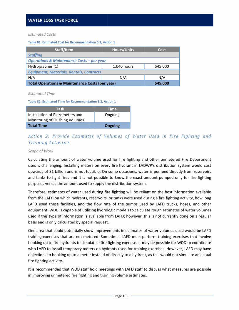
WATER LOSS TASK FORCE
Page100
Estimated Costs
Table 81: Estimated Cost for Recommendation 5.2, Action 1
Staff/Item Hours/Units Cost Staffing
Operations & Maintenance Costs – per year
Hydrographer (1) 1,040 hours $45,000
Equipment, Materials, Rentals, Contracts
N/A N/A N/A
Total Operations & Maintenance Costs (per year) $45,000
Estimated Time
Table 82: Estimated Time for Recommendation 5.2, Action 1
Task Time
Installation of Piezometers and Monitoring of Flushing Volumes
Ongoing
Total Time Ongoing
Action 2: Provide Estimates of Volumes of Water Used in Fire Fighting andTrainingActivities
Scope of Work
Calculating the amount of water volume used for fire fighting and other unmetered Fire Department
uses is challenging. Installing meters on every fire hydrant in LADWP’s distribution system would cost
upwards of $1 billion and is not feasible. On some occasions, water is pumped directly from reservoirs
and tanks to fight fires and it is not possible to know the exact amount pumped only for fire fighting
purposes versus the amount used to supply the distribution system.
Therefore, estimates of water used during fire fighting will be reliant on the best information available
from the LAFD on which hydrants, reservoirs, or tanks were used during a fire fighting activity, how long
LAFD used these facilities, and the flow rate of the pumps used by LAFD trucks, hoses, and other
equipment. WDD is capable of utilizing hydrologic models to calculate rough estimates of water volumes
used if this type of information is available from LAFD; however, this is not currently done on a regular
basis and is only calculated by special request.
One area that could potentially show improvements in estimates of water volumes used would be LAFD
training exercises that are not metered. Sometimes LAFD must perform training exercises that involve
hooking up to fire hydrants to simulate a fire fighting exercise. It may be possible for WDD to coordinate
with LAFD to install temporary meters on hydrants used for training exercises. However, LAFD may have
objections to hooking up to a meter instead of directly to a hydrant, as this would not simulate an actual
fire fighting activity.
It is recommended that WDD staff hold meetings with LAFD staff to discuss what measures are possible
in improving unmetered fire fighting and training volume estimates.

ACTION PLAN
Page101
Staffing Needs
One engineering associate and one water utility superintendent would be needed for these meetings.
Other staff needs would be determined at later date after both LADWP and LAFD plan and agree to an
improved method for monitoring fire fighting flows.
Equipment, Materials, Rentals, and Contract Needs
No additional equipment, materials, rentals, and contract needs are needed during the initial stage.
Estimated Costs
Table 83: Estimated Cost for Recommendation 5.2, Action 2
Staff/Item Hours/Units Cost Staffing
Capital Costs – 2 months
Engineering Associate (1) 40 hours $2,000
Water Utility Superintendent (1) 40 hours $3,000
Equipment, Materials, Rentals, Contracts
N/A N/A N/A
Total Capital Costs (for 2 months) $5,000
Estimated Time
Table 84: Estimated Time for Recommendation 5.2, Action 2
Task Time
Planning Meetings with LAFD 2 months
Total Time 2 months
RecommendedAction
Based on results from the previous FY 2010‐2011 Water Loss Audit and Component Analysis study, the
amount of unbilled, unmetered consumption in LADWP’s system was estimated to be 219 AF. However,
because this estimate is based on AWWA national standards and not on LADWP area‐specific volumes of
authorized unbilled and unmetered consumption, which are currently not fully known, this estimate
could be higher or lower than the actual value. Additionally, improving the estimates of unbilled,
unmetered authorized consumption volumes will improve subsequent estimates of water loss volumes
in LADWP’s system. This will improve the data quality and validity score of the “Unbilled unmetered”
entry on the AWWA water audit software.
Therefore, it is recommended to pursue both Actions 1 and 2 to determine if improvements can be
made to estimates of water main flushing and fire fighting activities in LADWP’s distribution system.

WATER LOSS TASK FORCE
Page102

ACTION PLAN
Page103
Conclusion
Table 85 provides a summary of recommended actions to improve the validity of data in the annual
LADWP water loss audit and to reduce water losses in LADWP’s water distribution system.
Table 85: Summary of Recommended Actions
Previous Study Recommendation Recommended Action(s) to Pursue Capital Cost O&M Cost
Section 1: System Input Volume
Recommendation 1.1: LA Aqueduct Filtration Plant System Input Volume Meters
Action 1: Track Volumes of Water Sources and System Water Supply Separately
Action 2: Regular Calibration of Relevant Supply Volume Meters at LAAFP
$5,000
N/A
N/A
$7,000
Recommendation 1.2: LA Reservoir West Outlet Meter Installation
Action 1: Calculate West Outlet Flow using Mass Balance
$2,000 N/A
Recommendation 1.3: Well Field Meter Accuracy and Regular Testing
Action 2: Installation of Flow Meters on Well Collector Lines
Action 3: Calibrate Collector Facility Meters
$1,128,000
N/A
N/A
$184,000
Recommendation 1.4: Storage Data Tracking
No Action (Action 1 not cost‐effective)
N/A N/A
Recommendation 1.5: MWD LA‐25 Connection Meter Installation
Action 1: Install an Ultrasonic Meter with Internal Mount Sensors
$383,000 N/A
Section 1 Total Estimated Costs of Proposed Actions $1,518,000 $191,000
Section 2: Database Management
Recommendation 2.1: SCADA Database Consolidation
No Action (Feasibility of Action 1 being evaluated)
N/A N/A
Recommendation 2.2: Recycled Water and Treatment Process Water Tracking
Action 1: Add a Recycled Water Identifier in the Billing System
Action 2: Create a Standard Procedure for Identifying Treatment Process Water in the Billing System
$29,000
$8,000
N/A
N/A
Recommendation 2.3: CIS and WMIS Inconsistencies
Action 1: Address the Remaining Duplicate Badge Numbers
$26,000 N/A
Recommendation 2.4: Leak Database Consolidation and Accuracy
Action 1: Develop a Second Pilot Mobile Leak Reporting System to Capture and Update Leak Information in Near‐Real Time
$20,000 N/A
Section 2 Total Estimated Costs of Proposed Actions $83,000 $0
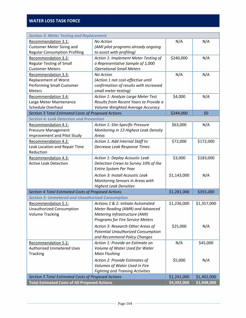
WATER LOSS TASK FORCE
Page104
Section 3: Meter Testing and Replacement
Recommendation 3.1: Customer Meter Sizing and Regular Consumption Profiling
No Action (AMI pilot programs already ongoing to assist with profiling)
N/A N/A
Recommendation 3.2: Regular Testing of Small Customer Meters
Action 1: Implement Meter Testing of a Representative Sample of 1,000 Operational Small Meters
$240,000 N/A
Recommendation 3.3: Replacement of Worst Performing Small Customer Meters
No Action (Action 1 not cost‐effective until confirmation of results with increased small meter testing)
N/A N/A
Recommendation 3.4: Large Meter Maintenance Schedule Overhaul
Action 1: Analyze Large Meter Test Results from Recent Years to Provide a Volume Weighted Average Accuracy
$4,000 N/A
Section 3 Total Estimated Costs of Proposed Actions $244,000 $0
Section 4: Leak Detection and Prevention
Recommendation 4.1: Pressure Management Improvement and Pilot Study
Action 1: Site‐Specific Pressure Monitoring in 13 Highest Leak Density Areas
$63,000 N/A
Recommendation 4.2: Leak Location and Repair Time Reduction
Action 1: Add Internal Staff to Decrease Leak Response Times
$72,000 $172,000
Recommendation 4.3: Active Leak Detection
Action 1: Deploy Acoustic Leak Detection Crews to Survey 10% of the Entire System Per Year
Action 3: Install Acoustic Leak Monitoring Sensors in Areas with Highest Leak Densities
$3,000
$1,143,000
$183,000
N/A
Section 4 Total Estimated Costs of Proposed Actions $1,281,000 $355,000
Section 5: Unmetered and Unauthorized Consumption
Recommendation 5.1: Unauthorized Consumption Volume Tracking
Actions 1 & 2: Initiate Automated Meter Reading (AMR) and Advanced Metering Infrastructure (AMI) Programs for Fire Service Meters
Action 3: Research Other Areas of Potential Unauthorized Consumption and Recommend Policy Changes
$1,236,000
$25,000
$1,357,000
N/A
Recommendation 5.2: Authorized Unmetered Uses Tracking
Action 1: Provide an Estimate on Volume of Water Used for Water Main Flushing
Action 2: Provide Estimates of Volumes of Water Used in Fire Fighting and Training Activities
N/A
$5,000
$45,000
N/A
Section 5 Total Estimated Costs of Proposed Actions $1,241,000 $1,402,000
Total Estimated Costs of All Proposed Actions $4,392,000 $1,948,000
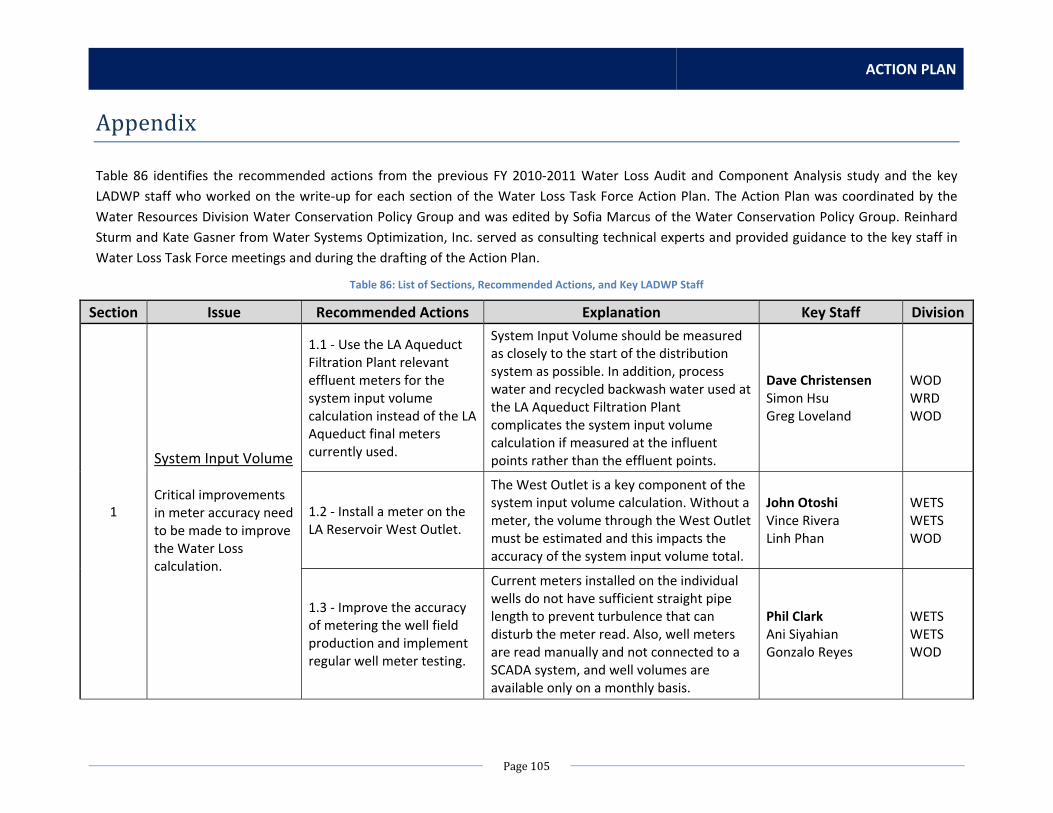
ACTION PLAN
Page105
Appendix
Table 86 identifies the recommended actions from the previous FY 2010‐2011 Water Loss Audit and Component Analysis study and the key
LADWP staff who worked on the write‐up for each section of the Water Loss Task Force Action Plan. The Action Plan was coordinated by the
Water Resources Division Water Conservation Policy Group and was edited by Sofia Marcus of the Water Conservation Policy Group. Reinhard
Sturm and Kate Gasner from Water Systems Optimization, Inc. served as consulting technical experts and provided guidance to the key staff in
Water Loss Task Force meetings and during the drafting of the Action Plan.
Table 86: List of Sections, Recommended Actions, and Key LADWP Staff
Section Issue Recommended Actions Explanation Key Staff Division
1
System Input Volume Critical improvements in meter accuracy need to be made to improve the Water Loss calculation.
1.1 ‐ Use the LA Aqueduct Filtration Plant relevant effluent meters for the system input volume calculation instead of the LA Aqueduct final meters currently used.
System Input Volume should be measured as closely to the start of the distribution system as possible. In addition, process water and recycled backwash water used at the LA Aqueduct Filtration Plant complicates the system input volume calculation if measured at the influent points rather than the effluent points.
Dave Christensen Simon Hsu Greg Loveland
WOD WRD WOD
1.2 ‐ Install a meter on the LA Reservoir West Outlet.
The West Outlet is a key component of the system input volume calculation. Without a meter, the volume through the West Outlet must be estimated and this impacts the accuracy of the system input volume total.
John Otoshi Vince Rivera Linh Phan
WETS WETS WOD
1.3 ‐ Improve the accuracy of metering the well field production and implement regular well meter testing.
Current meters installed on the individual wells do not have sufficient straight pipe length to prevent turbulence that can disturb the meter read. Also, well meters are read manually and not connected to a SCADA system, and well volumes are available only on a monthly basis.
Phil Clark Ani Siyahian Gonzalo Reyes
WETS WETS WOD

WATER LOSS TASK FORCE
Page106
Section Issue Recommended Actions Explanation Key Staff Division
1
System Input Volume (continued from previous page) Critical improvements in meter accuracy need to be made to improve the Water Loss calculation.
1.4 ‐ Track all reservoir level data (and other data related to storage volumes).
Not all storage volume data is available on SCADA, and the storage volume currently reported on a monthly basis contains an estimated volume for all reservoirs with insufficient data.
Linh Phan Robert Tokashiki
WOD WOD
1.5 ‐ Install a meter on the LA‐25 MWD connection.
LA‐25 supplies water to LADWP when the LA Aqueduct Filtration Plant is down for maintenance. LA‐25 is not directly metered, and the volume delivered is therefore calculated by mass balance through the Jensen Treatment Plant.
John Otoshi Vince Rivera Du Tran
WETS WETS WETS
2
Database Management Data should be organized in a more efficient manner. Some of the data also has issues with accuracy and/or needs to be updated.
2.1 ‐ Streamline the multiple SCADA systems that house all of the system input volume data.
Data from the meters relevant to the system input volume calculation are not located in one SCADA system, but at least three systems ‐ LAWSDAC, TOCC/Wave Server, and Northern District Hydrologic Database (Bishop). The data needs to be streamlined into one easy‐to‐use system that is easily accessible by Water Resources staff.
Robert Tokashiki WOD
2.2 ‐ Re‐categorize recycled water and process water accounts in the billing system if they are not already properly coded.
All recycled water accounts should be categorized as Rate Code 44 in CIS and excluded from the water loss audit analysis as they are not a part of the potable water demand. Two accounts related to LA Aqueduct Filtration Plant process water should also be re‐catgorized in CIS and excluded from the analysis.
Flora Chang Kathy Wright Don Cresse
ITS ITS WETS
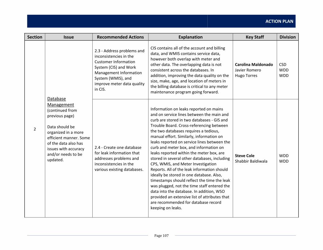
ACTION PLAN
Page107
Section Issue Recommended Actions Explanation Key Staff Division
2
Database Management (continued from previous page) Data should be organized in a more efficient manner. Some of the data also has issues with accuracy and/or needs to be updated.
2.3 ‐ Address problems and inconsistencies in the Customer Information System (CIS) and Work Management Information System (WMIS), and improve meter data quality in CIS.
CIS contains all of the account and billing data, and WMIS contains service data, however both overlap with meter and other data. The overlapping data is not consistent across the databases. In addition, improving the data quality on the size, make, age, and location of meters in the billing database is critical to any meter maintenance program going forward.
Carolina Maldonado Javier Romero Hugo Torres
CSD WDD WDD
2.4 ‐ Create one database for leak information that addresses problems and inconsistencies in the various existing databases.
Information on leaks reported on mains and on service lines between the main and curb are stored in two databases ‐ GIS and Trouble Board. Cross‐referencing between the two databases requires a tedious, manual effort. Similarly, information on leaks reported on service lines between the curb and meter box, and information on leaks reported within the meter box, are stored in several other databases, including CPS, WMIS, and Meter Investigation Reports. All of the leak information should ideally be stored in one database. Also, timestamps should reflect the time the leak was plugged, not the time staff entered the data into the database. In addition, WSO provided an extensive list of attributes that are recommended for database record keeping on leaks.
Steve Cole Shabbir Baldiwala
WDD WDD

WATER LOSS TASK FORCE
Page108
Section Issue Recommended Actions Explanation Key Staff Division
3
Meter Testing and Replacement Customer meter testing should occur regularly and consumption profiles should be analyzed on a regular basis.
3.1 ‐ Investigate the improperly‐sized meters/accounts highlighted in Appendix E. Develop a future schedule for regular consumption profiling.
Meters that are too small for the relatively larger consumption rates will not accurately read the volumes passing through the meter. Vice versa, meters that are too large for small consumption rates will not accurately read the small volumes. This affects the accuracy of the total demand volume calculated. Meters that are too small or too large for the amount of consumption used as shown by the billing database should be tested and potentially replaced by an appropriate size.
Javier Romero Ricky Glover Kathy Wright Flora Chang
WDD WDD ITS ITS
3.2 ‐ Perform regular testing of an appropriate, representative sample of small and large customer meters.
Most customer meters are not tested on a regular basis and may be under‐registering or otherwise non‐functional. Perform regular testing of random small meter samples (100‐200 meters per year).
Javier Romero Ricky Glover Kathy Wright Flora Chang
WDD WDD ITS ITS
3.3 ‐ Replace the worst‐performing small customer meters.
A representative sample of around 1,000 small meters conducted during the Water Loss Audit study indicated the worst‐performing meters out of the ones tested were Sensus meters of these sizes: 5/8 x 3/4", 3/4 x 1", 1 1/2", and 2".
Ricky Glover WDD
3.4 ‐ Overhaul the large meter maintenance schedule to target more frequent maintenance and replacement of large customer meters with the highest consumption rates (based on past usage).
WSO provided a recommended overhaul schedule of the large customer meters in Section 10.2. For the top one hundred large customer meters (ranked by revenue generated), it is recommended to undertake consumption profiling and targeted selection of appropriate metering technology.
Ricky Glover WDD

ACTION PLAN
Page109
Section Issue Recommended Actions Explanation Key Staff Division
4
Leak Detection and Prevention There is not enough data available to accurately assess system zone typical flow, pressure, and leak potential.
4.1 ‐ Improve pressure management through implementation of a pilot study.
Most system zones are operated at high pressures. High pressures can put strain on the infrastructure and contribute to system leakage. If possible, determine ways to decrease pressure within the system zones. WSO provided recommendations to implement a pilot study for pressure management in Section 11.4.
Todd Huynh Todd Le Linh Phan Gary Warden Marce‐Adrian Perez Russell Pierson
WDD WDD WOD WOD WETS WETS
4.2 ‐ Reduce the average location and repair time for main leaks, service connection leaks, and appurtenance leaks.
An initial modeling of savings suggests that a significant real loss reduction could be achieved (approximately $1.6 million annually based on MWD water rates) if the average location and repair time was reduced by 50%. This initial savings analysis is based on the average location and repair time as determined from the leak repair records from FY 2010‐2011; before response time improvements are pursued, it is important to revisit the reliability and completeness of the response time data.
Jeff Bray WDD
4.3 ‐ Implement a regular active leak detection program to the extent that is cost‐effective.
Active leak detection can find leaks in pipes that have not yet surfaced and prevent damage to above‐ground infrastructure through proactive leak repair. WSO recommends targeting 10‐15% of the distribution network for leak detection surveying each year.
Charles Ngo Dean Terada Cree Horner
WETS WETS WDD

WATER LOSS TASK FORCE
Page110
Section Issue Recommended Actions Explanation Key Staff Division
5
Track Authorized Unmetered and Unauthorized Consumption
5.1 ‐ Track and estimate volumes lost from unauthorized consumption (theft).
Currently, an AWWA standard percentage estimate is applied as the theft volume. Better estimates based on LADWP‐specific information should be calculated to improve the accuracy of this number. Read fire service meters on a regular basis to determine if unauthorized consumption is occurring. Consider reading customer meters on irregular days (like Sundays) every once and a while and/or install Advanced Metering Infrastructure (AMI) to catch any meter tampering that may occur.
Wayne Wohler Kim Versluis Carolina Maldonado Javier Romero Ricky Glover Kathy Wright Flora Chang
CSD CSD CSD WDD WDD ITS ITS
5.2 ‐ Track and estimate volumes from authorized unmetered unbilled uses (such as fire fighting and system flushing).
Currently, an AWWA standard percentage estimate is applied as the unmetered unbilled volume. Better estimates based on LADWP‐specific information should be calculated to improve the accuracy of this number.
Cree Horner Alvin Bautista Mike Downs
WDD WDD WDD