Xps battery, vostro battery, inspiron battery, studio battery, batterylovers.com

For Installers
Installation ManualHybrid Solar Inverter (5.5 kW) (For Outdoor Installation)Product Number: THD-S55P3B-US
Thank you for purchasing this product from Tabuchi Electric.■ The Institute of Electrical and Electronics Engineers
(IEEE) or Hawaiian Electric Company (HECO) settings can be applied to this product (refer to pages 37 - 38).
■ This product must be correctly installed in order for it to perform and function sufficiently, and to ensure safety.
■ Be sure to read these instructions prior to installing the product.
■ Be sure to read the section “IMPORTANT SAFETY INSTRUCTIONS” and “Installation Precautions” (Pages 2 - 7)
■ To ensure safety, have a qualified person perform installation wiring in accordance with laws and regulations.
Table of ContentsIntroduction
IMPORTANT SAFETY INSTRUCTIONS 2Installation Precautions 5Acceptance Flow 7System Diagram & Components 8Components (Names & Functions) 12
InstallationPreparations 15Inverter Installation 16Wiring Installation 21AC Connection Requirements 23WIRING SCHEMATIC OF SINGLE PHASE SYSTEM 28
Setup/Check Stand-alone Operation Check 32Parameters List 37Parameter Setting 39Grid-tied Operation Check 42Troubleshooting 45Checking the PV System for Ground Faults 47Specifications 48Arc Fault Circuit Protection 49FCC Compliance 50
● The content in this Installation Manual is meant for installers.
● After installation/configuration, give this manual to the person responsible for maintenance and inspection and store it in a safe place.

2
IMPORTANT SAFETY INSTRUCTIONSSAVE THESE INSTRUCTIONS
This manual contains important instructions for the THD-S55P3B-US.This manual contains important instructions that must be followed during installation and maintenance.The product is designed and tested in accordance with international safety requirements, however as with all electrical and electronic equipment, certain precautions must be observed when installing and/or operating this product.To reduce the risk of personal injury and to ensure the safe installation and operation of this product, carefully read and follow all instructions, caution statements, and warnings in this manual.
Product Safety WarningsThe following symbols are used as safety indicators on this product. The meaning of these symbols is explained below.
Symbol Description
Dangerous Voltage WarningThe symbol of a lightning bolt with an arrow inside of a triangle notifies the user that there is a risk of electric shock. This product uses high levels of voltage and the parts inside this product may cause personal injury due to electric shock. All work performed on this product must be as described in the documentation for this product.
CAUTION: Hot SurfaceThis product heats up during operation. Do not touch the product while it is in operation.Observe all operating instructions.
General WarningsTHESE SERVICING INSTRUCTIONS ARE FOR USE BY QUALIFIED PERSONNEL ONLY.TO REDUCE THE RISK OF ELECTRIC SHOCK, DO NOT PERFORM ANY SERVICING OTHER THAN THAT SPECIFIED IN THE OPERATING INSTRUCTIONS UNLESS YOU ARE QUALIFIED TO DO SO.
All electrical installations must be made in accordance with the local and National Electrical Code® ANSI/NFPA 70 or the Canadian Electrical Code®, Part I.This document does not and is not intended to replace any local, state, provincial, federal or national laws, regulation or codes applicable to the installation and use of this product, including without limitation applicable electrical safety codes.All installations must conform with the laws, regulations, codes and standards applicable in the jurisdiction of installation.TABUCHI ELECTRIC assumes no responsibility for the compliance or non-compliance with such laws or codes in connection with the installation of the product.This product contains no user-serviceable parts. For all repairs and maintenance, always return the unit to an authorized TABUCHI ELECTRIC Service Center.Before installing or using the product, read all of the instructions, cautions, and warnings in this manual. Before connecting the product to the electrical utility grid, contact the local utility company. Only qualified technical persons are allowed to connect this product to the utility grid. Wiring of the product must only be performed by qualified technical persons. The safety precautions in this manual do not replace the safety regulations enforced in the country where this product is installed. Maintenance must be carried out according to the maintenance section of this manual.Do not use the equipment if any operational anomalies are found. Liabilities associated with commercial components are delegated to the respective manufacturers.

3
■ The symbols below indicate the potential hazards of improper installation or use of this product.
■ The symbols below indicate prohibited use of this product and mandatory safety precautions.
● Do not short-circuit the positive (+) terminal cables (black) or negative (-) terminal cables (white) of the solar panels and storage battery unit.
Short-circuits may cause a fire or electric shock.
● During installation and wiring work, follow all safety precautions.
Failure to do so may result in electric shock or equipment failure.● Keep all switches in the OFF position until the
wiring is completed. This includes DC Switch-disconnector outside of the inverter, breakers in Backup Load Panel, grid-tied breaker in the ELECTRICAL SERVICE ENTRANCE, and the switch inside the storage battery unit.
● Confirm there is no live voltages before commencing installation work.
● Do not stand on wet ground or work with wet hands or body parts.
● Do not damage the wire sheathing.
● A battery can present a risk of electrical shock, burn from high shortcircuit current. Observe proper precautions.
● Wear protective gloves and use electrically insulated tools during installation and when installing electrical wiring work.
Unprotected hands may result in electric shock or injury.
WARNING
PROHIBITEDUSE
MANDATORY
MANDATORY
May result in serious injury or death.
May result in minor injury or property damage.
WARNING
CAUTION
Prohibited use of this product.
Mandatory safety precautions.
Do not connect to storage battery units other than our products “EOW-LB100-PNUS”.EOW-LB100-PNUS: Lithium-ion Storage Battery
Rated Capacity: 114.48 AhRated input/output: 86.4 VMax. output (discharging) current: 26 AGrounding configuration: ungrounded
The battery installation must be done in accordance with storage battery rules of National Electrical Code® ANSI/NFPA 70 or the Canadian Electrical Code®, Part I.The user should not exchange or relocate the storage battery unit. For information on recycling and discarding dead batteries, contact the vendor or the installer.

4
● Do not drill or cut entry holes in the inverter. Debris from drilling may adhere to the circuit
boards resulting in fire or equipment failure.● Do not mix up the DC wires from the solar
panels and the storage battery unit with the AC wires from the grid.
Incorrect wiring may damage the equipment.
● Use wiring of the recommended wire gauge and connect wiring to the terminal blocks using the specified crimp terminal.
Inadequate wiring materials and connections may result in fire or equipment failure.
● Fill wiring holes with putty in order to seal the inverter against weather and pests.
Fire and/or equipment trouble may occur.● Install the inverter in well-ventilated areas. Poor ventilation may cause fire.● Observe IMPORTANT SAFETY
INSTRUCTIONS (Page 2). Fire or accidents may occur if not followed.
● Install the inverter on a surface that can withstand the weight of the product.
Reinforce walls if necessary. Installation should be completed by two or
more qualified professionals. Inadequate installation may cause the inverter
to tip over or incur other types of damage.
CAUTION
PROHIBITEDUSE
MANDATORY
MANDATORY

5
Installation Precautions Electrical Connection Warnings
This grid-tied inverter system operates only when properly connected to the AC utility grid.Utility interconnection may require approval from the authority having jurisdiction.Before connecting this inverter to the AC utility grid, contact the local utility company to receive proper approval.Connection to the AC utility grid must only be made by qualified technical persons.Wiring methods should conform to the National Electric Code® ANSI/NFPA 70, and/or any prevailing local codes and regulations.AC output circuits are isolated from the enclosure. System grounding, as required by Sections 690.41 - 690.43 of the National Electric Code® ANSI/NFPA 70 or the Canadian Electrical Code®, Part І is the responsibility of the installer.The inverter should only be connected to a dedicated branch circuit.For models that do not include AC output overcurrent protection, it is the responsibility of the end user to provide protection for the AC output circuit.Connect only to a circuit provided with the maximum branch overcurrent protection device (e.g., AC circuit breaker).
This inverter must only be used in ungrounded PV systems. Do not use grounded PV modules with this inverter. Ground only the mounting frame for the PV modules. All DC inputs of an ungrounded PV system must be equipped with overcurrent protection according to the National Electrical Code® NEC 690. This inverter must be installed per the requirements contained in Section 690.35 of the National Electrical Code® ANSI/NFPA 70.
WARNINGThis inverter has a transformerless design and requires connected array(s) to be floating with respect to ground.Only use with PV modules that do not require one of the terminals to be grounded.Do not use grounded PV modules with this inverter.Only ground the mounting frame for the PV module.PV modules with a high capacity to ground may only be used if their coupling capacity does not exceed 1400nF.If the inverter is connected to grounded PV modules, error insulation resistance occurs.● The AC output/neutral is not bonded to ground inside of the inverter.● The DC and AC operating currents MUST NOT exceed the limits documented in the technical specifications.● The inverter can only be used if all the technical requirements in this manual are observed and applied.
All components must remain within their permitted operating ranges at all times.For safety reasons, modification of this product is prohibited along with the installation of components that are not specifically recommended or distributed by TABUCHI ELECTRIC for this product.This product must only be used in countries for which it is approved or released by TABUCHI ELECTRIC and the grid operator.Use this product only in accordance with the information provided in the enclosed documentation, and with the locally applicable standards and directives. Any other use may result in personal injury or property damage.Do not install or connect the inverter as described below.● Do not mount this product in salty regions (within 500 m (1640 ft.) of coast lines, or locations subject to direct sea
breezes).● Do not mount this product in locations where ambient temperature is below -20°C (-4°F) or above 40°C (104°F).
(Avoid direct sunlight.)● Do not mount this product in highly humid areas.● Do not mount this product in locations where the required installation space cannot be secured.(See “Preparations”
on Page 15.)● Do not mount this product at elevations exceeding 1000 m (3280 ft.).● Do not mount this product in locations where temperature fluctuates drastically (where condensing occurs).● Do not mount this product in locations subjected to stringent noise regulations (Less than 44 dB).

6
● Do not install this product on flammable construction materials.● Do not mount this product in locations where it may be exposed or possibly exposed to excessive steam, oily mist,
smoke, dust, salt, corrosive materials, explosive/flammable gases, chemical agents, or fire.● Do not install in locations where vents may be blocked by the accumulation of snow.
(For areas with significant snowfall, install the inverter under a roof or in an enclosure.)● Do not install in locations that are subject to large vibrations or impacts.● Do not install in locations where wiring holes cannot be drilled into exterior walls.
The enclosed documentation is an integral part of this product.● Read and observe all safety warnings, precautions, and instructions in the documentation.● Keep documentation in a convenient place for future reference.
Knowledge & Skills of Qualified PersonsThe tasks described in this document must only be performed by qualified technical persons.Qualified technical persons must possess the following knowledge and skills.● Knowledge of how an inverter works and is operated.● Training in how to deal with the dangers and risks associated with installing and using electrical devices and
systems.● Training in the installation and commissioning of electrical devices and systems.● Knowledge of the applicable standards and directives.● Knowledge of and adherence to this document and all safety precautions.
Safety PrecautionsThis section contains safety precautions that must be observed at all times when working on or with this product.To prevent personal injury and property damage and to ensure long-term operation of this product, read this section carefully and follow all safety precautions at all times.
DANGERHigh voltage levels are used while operating this product and pose a risk of electric shock.High levels of voltage that pose a risk of fatal or serious injury due to electric shock are present in the live components of this inverter.● All work on the inverter must only be carried out by qualified technical persons.● DO NOT TOUCH any live components.
Follow the steps below before working on the inverter:1. Switch off all devices that are connected to the inverter and take precautions against the possibility of
reconnection.The Overcurrent Protection device (e.g., AC circuit breaker)2. Cover the PV modules.3. Turn the inverter DC Switch-disconnector counterclockwise by 90° and set to OFF.
Prior to performing any work on the inverter, disconnect all voltage sources as described in this document, and wait 5 minutes.● All work on the inverter should only be carried out as described in this document.
DANGER Risk of fatal or serious injury due to electric shock caused by a ground fault.If a ground fault occurs, parts of the system may still be live. Death or serious injury due to contact with live components may occur.● Ensure that no voltage is present and wait 5 minutes before touching any part of the PV system or the inverter.

7
Acceptance FlowPreparations Page 15
Inverter Installation Page 16
Wiring Installation Page 21
Stand-alone Operation Check Page 32
Coordination with the Power Company Page 37
Parameter Setting Page 39
Grid-tied Operation Check Page 42
Customer Consultation/Explanation
Start of Grid-tied Operation
Install the inverter and Remote Controller.
Set parameters such as line excessive voltage.
DANGER Risk of serious burn injuries from hot surfaces.The surface of the inverter can get very hot. Touching the surface of the inverter may cause burns.● Mount the inverter so that it cannot be touched accidently.● Do not touch hot surfaces.● Wait 30 minutes for the surface to cool sufficiently.
WARNINGDamage due to intrusion of moisture and dust.Intrusion of moisture and dust can damage the inverter and impair functionality.● Tightly close all inverter enclosure openings.● Never open the inverter when it is raining, snowing, or when the humidity is over 90%.
DANGER Risk of death or serious injury due to operating damaged equipment.Operating a damaged inverter can lead to fatal or serious injuries from electric shock.● Only operate the inverter when it is fully functional.● Regularly check the inverter for visible damage.● Ensure that all safety equipment is freely accessible at all times.
8
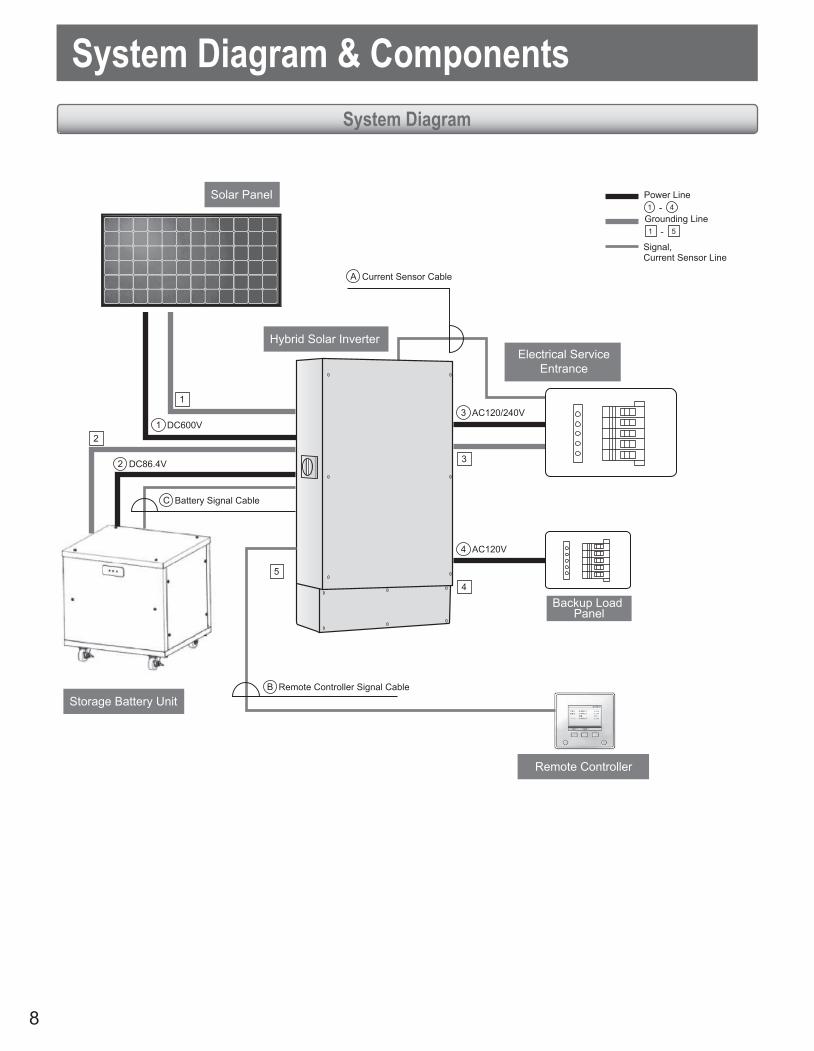
System Diagram & ComponentsSystem Diagram
Power Line
Signal, Current Sensor Line
Current Sensor CableA
DC600V1
DC86.4V2
AC120/240V3
AC120V4
1
1 5
2
3
4
5
1 4-
-
Remote Controller Signal CableB
Battery Signal CableC
Grounding Line
Solar Panel
Backup Load Panel
Storage Battery Unit
Hybrid Solar Inverter
Remote Controller
Electrical ServiceEntrance

9
■ AccessoriesPart Qty Part Qty
Remote Controller (With bracket) 1 Base 1
Screw for Remote Controller BracketM4 x 16 2 Remote Controller
Signal Cable 30 m (98.4 ft) 1
Attachment 1 Battery Signal Cable 30 m (98.4 ft) 1
Bracket 1 Current Sensor Cable 30 m (98.4 ft) 1
Flange Nut M6 1 Shelf 1
Current Sensor 2 Hex Bolt M12 x 30 4
Base Hex Bolt M8 x 25 4 Flange Nut M12 4
Test Results 1 Screw for Shelf M6 x 75 4
Guide Manual 1 Installation Manual (for Shelf) 1
■ Power LinePower Line Distribution Recommended Wire Gauge x Max. Wire Length
① DC Match to solar panel specifications.
② DC CV 2 Conductors AWG 8 x 10 m (32.8 ft)
③ 1φ3W CV 3 ConductorsAWG 10 x 20 m (65.6 ft), AWG 8 x 30 m (98.4 ft)
④ 1φ2W CV 2 ConductorsAWG 10 x 15 m (49.2 ft), AWG 8 x 25 m (82.0 ft)
■ Grounding LinePower Line Recommended Wire Gauge
1 Match to solar panel specifications.
2 IV 1 conductor AWG 8
3 IV 1 conductor AWG 8

10
Remote Controller Signal Cable (30 m (98.4 ft) long)
Remote Controller side connector
(For grounding)
Inverter side connector
● Remote Controller side connector
● Inverter side connector
112.
8 m
m (4
.4 in
)
83.5
mm
(3.3
in)
59.4 mm(2.3 in)
46 mm (1.8 in) 1 mm (0.04 in)
φ34.8 mm(1.4 in)
7 mm (0.28 in)4.5 mm
11.7
mm
8 mm (0.32 in)
12.3 mm (0.48 in)
14.8
mm
(0.58
in)
(0.18 in)
(0.46
in)
22.8 mm (0.9 in)130 mm (5.1 in)
120
mm
(4.7
in)
Dimensions
■ Hybrid Solar Inverter
■ Remote Controller
680 mm (26.8 in) 36 mm(4.1 in)
450 m
m (1
7.7 in
)85
mm(3.3
in)
1000
mm
(39.
4 in
)20
0 mm
(7.8
in)20
2 mm
(8 in
)
1402
mm
(55.
2 in
)
250 mm (9.8 in) 298 mm (11.7 in)
268 mm (11 in) 630 mm (24.8 in)
145 m
m(5.
7 in)
2 - φ22 mm (0.9 in)6 - φ28 mm (1.1 in)4 - φ49 mm (1.9 in)
11
■ Current Sensor32 mm (1.26 in)
46.5
mm (1
.83 in
)
31 m
m
φ16 mm (0.63 in)
23.6 mm(0.93 in)
30 mm(1.18 in)
Current Sensor Cable (30 m (98.4 ft) long)
Black: L White: K
Current Sensor side connector
Inverter side connector
● Current Sensor side connector
● Inverter side connector
L1
L2
8.5 mm(0.34 in)
10.5
mm (0
.41 in
)
24.5 mm(0.97 in)
9.6 mm(0.38 in)
7 mm(0.28 in)
14.8
mm
*Power cable should be AWG 1 or less.
(1.22
in)
(0.5
8 in
)

12
Components (Names & Functions) ■ Hybrid Solar Inverter & Base
Vents
Hybrid Solar Inverter
Charging Area
Sectionneur-commutateur cc
Base
Wiring Area
Wiring Cover
Storage Battery Unit Terminals
Grid-tied Input/Output and Stand-alone Output Terminals
Solar Panel Input Terminals

13
Displays functions that are executed from the below operating buttons below. (Indications change according to the screen.)Use the operating buttons below to execute the desired functions.(The display is not a touch screen panel.)To select function [ENTER], press the operating button directly below it.
Button Name on Display Area
RUN/STOP Button
How to read RUN/STOP Button
Button colors and functions
Displays operating status of the inverter.Display
Green: Running grid-tied operationRed: Running stand-alone operationFlashing red: Automatically stopped
Execute the functions appearing on the display. (If the display disappears, pressing any of the operating buttons lights up the display and the home screen appears.)
Operating Button
GRID-TIED MODE:Green(SELL) :Orange(BUY)STAND-ALONE MODE:GreenOthers:Lights OFF
Lights OFF: Grid-tied operation manually stoppedStand-alone operation manually stoppedGrid-tied operation standby Stand-alone operation standby
This button does not operate if there is a grid outage, no solarpower being generated, or if thestorage batteries are not charged (drained, disconnected,or stopped due to a malfunction.)
■ Remote Controller

14
■ Type Label and Additional Label
The type label uniquely identifies the inverter.The information on the type label is required for safe use of the inverter.For customer support assistance from the TABUCHI ELECTRIC Service Line, the type label must remain permanently attached to the inverter.
Symbols on These LabelsSymbol Explanation
Risk of fatal or serious injury due to electric shock from high voltage levels.This product uses high voltage levels for operation. All work on the product must only be carried out by qualified technical persons.Risk of burns from hot surfaces.This product can get hot during operation. Avoid contact with the inverter during operation.Allow the product to cool down sufficiently before carrying out any work.Wear personal protective equipment, such as safety gloves.
Certification MarkUL1741 Standard for Safety for Inverters, Converters, Controllers and Inter-connection System Equipment for use with Distributed Energy Resources.CSA-C22.2 No. 107.1-01 - General Use Power Supplies.
ELECTRIC SHOCK HAZARDDo not remove cover. Only qualified service personnel should service the inverter.
Hot surfaces – To reduce the risk of burns,do not touch.
• Both AC and DC voltage sources are terminated inside this equipment. Each circuit must be individually disconnected before servicing.
• When the photovoltaic array is exposed to light, it supplies a DC voltage to this equipment.
Ne pas ouvrir le couvercle. Seul le personnel d'entretien qualifié doit être autorisé à procéder à l'entretien de l'inverseur.
Surfaces chaudes – Pour réduire le risquede brûlure, ne pas toucher.
• Cet équipement est alimenté par des sources de tension de courant alternatif (ca) et de courant continu (cc). Débrancher individuellement chacun des circuits avant de procéder à l'entretien.
• Quand le réseau de photopiles est exposé à la lumière, cet équipement est alimenté par une tension de courant continu.
DANGER D'ÉLECTROCUTION
15
200 mm (7.9 in)
200 mm (7.9 in)500 mm (19.7 in) 800 mm (31.5 in)
50 to 120 mm (2.0 to 4.7 in)
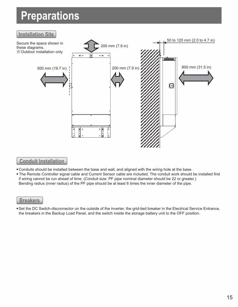
PreparationsInstallation Site
Conduit Installation
Breakers
Secure the space shown in these diagrams.※ Outdoor installation only
● Conduits should be installed between the base and wall, and aligned with the wiring hole at the base.● The Remote Controller signal cable and Current Sensor cable are included. The conduit work should be installed first
if wiring cannot be run ahead of time. (Conduit size: PF pipe nominal diameter should be 22 or greater.) Bending radius (inner radius) of the PF pipe should be at least 6 times the inner diameter of the pipe.
● Set the DC Switch-disconnector on the outside of the inverter, the grid-tied breaker in the Electrical Service Entrance, the breakers in the Backup Load Panel, and the switch inside the storage battery unit to the OFF position.

16
Inverter Installation
Inverter Installation
● Install the attachment to prevent overturning. Overturning of the device could result in injury.WARNING
MANDATORY
■ Installing the shelf1 Secure the shelf to a wall using 4 tapping screws
before installing the device● Select the holes to use for securement in alignment with
studs in the wall.
2 Secure the base to the shelf with 4 M12 bolts/nuts
3 Secure the attachment to a wall using 2 tapping screws● Select the holes to use for securement in alignment with studs
in the wall.
Studs
Wall
Attachment
Tapping screw
1234
mm
(48.
6 in
)
305 mm (12 in)406 mm (16 in)610 mm (24 in)660 mm (26 in)
91.5
mm(3.
6 in)
22 mm(0.87 in)
9 m
m(0
.35
in)
Shelf
Studs
Tapping screw
Attachment
305 mm (12 in)
1234
mm
(48.
6 in
)
208
mm
(8.2
in)
120
mm
(4.7
in)
406 mm (16 in)610 mm (24 in)
680 mm (26.7 in)
Φ 9

17
Wiring Cover
Remove screws
Base Front Panel
※ Be sure to keep the screws in a safe place.
4 Detach the front panels from the Hybrid Solar Inverter and the base. Detach the wiring cover from the Hybrid Solar Inverter① Remove the screws (6) from the front panel of the Hybrid Solar Inverter and detach the
panel.
② Remove the screws (6) from the front panel of the base and detach the panel.
③ To detach the cover and remove the screws (4) from the wiring cover.
Front Panel
Remove screws

18
Level Gauge
Base
Shelf
Base
Shelf
Conduit Connector
5 Install the base on the shelf.① Place the base on the shelf.② Use a level gauge to adjust the base so
that it sits flat in all directions.
6 Connecttheflexibleplasticconduitconnectorstotheshelf.
③ Anchor the base on a shelf with hex bolts.Hex bolt size: M12 (1/2-20)Adjust the bolt length according to the installation surface.Tightening torque: 40 to 50 Nm (29.5 to 36.9 ft·lb)

19
Wires
Putty
7 Feedthewiresintothebase,andfilltheinside of the wiring opening with putty.● Feed each wire into the base through the opening.
8 Place the Hybrid Solar Inverter on the base.① Place the Hybrid Solar Inverter on the
base.② Connect the Hybrid Solar Inverter and
base with the supplied locking bolts (4).Tightening torque: 8 to 13 Nm (5.9 to 9.6 ft·lb)
9 Feed the wires into the Hybrid Solar Inverter.Feed each wire into the Hybrid Solar Inverter through the wiring holes.
4 - ø49mm(1.9 in)
6 - ø28mm(1.1 in)2 - ø22mm(0.9 in)

20
Installing the Remote Controller
If there is exposed wiring, break off the tab at the point where the cable extends beyond the Remote Controller.
Break off the tab
A
A
B
B
LAN cable*(without boot)
* This cable is used to connect to networks such as the Internet.
Clamp
LAN cable connector
1 Attach the bracket to the wall.● The connectors at the two ends of the signal cable are different
sizes. Check the connector size and connect the smaller one to the
Remote Controller.● Lock the bracket to the wall with screws with the sign of “UP”
shown on the bracket is on the top.● To attach the bracket to the wall using the screws (M4 x 16)
provided with the Remote Controller package.
Notes● Pay attention not to pinch the cable between the bracket and wall surface.● Do not excessively tighten the screws when locking the bracket to the wall. Excessive force will bend the bracket and make it difficult to mount the Remote Controller. (Exercise caution when using the electric screwdriver.)
If attaching the Remote Controller to a switchbox.Use hole A if attaching the Remote Controller to a one-socket switchbox. Use the hole B if attaching it to a two-socket switch box. Lock the Remote Controller to the switchbox using the screws supplied with the switchbox.
2 Connect the signal cable to the Remote Controller.① Connect the signal cable connector to the connector
on the back of the Remote Controller.
Notes ● Insert the connector all the way into the socket.● Insert the LAN cable into the connector illustrated
in the figure to connect to networks such as the Internet.
② After confirming that the connector is securely inserted into the socket, tuck the cable into the clamp to lock it in place.
21
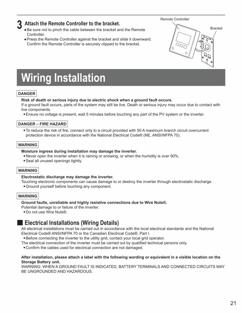
3 Attach the Remote Controller to the bracket.● Be sure not to pinch the cable between the bracket and the Remote
Controller.● Press the Remote Controller against the bracket and slide it downward. Confirm the Remote Controller is securely clipped to the bracket.
Remote Controller
Bracket
Wiring InstallationDANGER
Risk of death or serious injury due to electric shock when a ground fault occurs.If a ground fault occurs, parts of the system may still be live. Death or serious injury may occur due to contact with live components.● Ensure no voltage is present, wait 5 minutes before touching any part of the PV system or the inverter.
DANGER – FIRE HAZARD● To reduce the risk of fire, connect only to a circuit provided with 50 A maximum branch circuit overcurrent
protection device in accordance with the National Electrical Code® (NE, ANSI/NFPA 70).
WARNINGMoisture ingress during installation may damage the inverter.● Never open the inverter when it is raining or snowing, or when the humidity is over 90%.● Seal all unused openings tightly.
WARNINGElectrostatic discharge may damage the inverter.Touching electronic components can cause damage to or destroy the inverter through electrostatic discharge.● Ground yourself before touching any component.
WARNINGGround faults, unreliable and highly resistive connections due to Wire Nuts®.Potential damage to or failure of the inverter.● Do not use Wire Nuts®.
■ Electrical Installations (Wiring Details)All electrical installations must be carried out in accordance with the local electrical standards and the National Electrical Code® ANSI/NFPA 70 or the Canadian Electrical Code®, Part I.● Before connecting the inverter to the utility grid, contact your local grid operator.
The electrical connection of the inverter must be carried out by qualified technical persons only.● Confirm the cables used for electrical connection are not damaged.
After installation, please attach a label with the following wording or equivalent in a visible location on the Storage Battery unit.WARNING: WHEN A GROUND FAULT IS INDICATED, BATTERY TERMINALS AND CONNECTED CIRCUITS MAY BE UNGROUNDED AND HAZARDOUS.

22
Do not measure resistancebetween the terminals.
Measure resistancebetween the wires.
Inverter Inverter
InsulationTester Insulation
TesterStorage Battery Unit
Storage Battery Unit
● Wear protective gloves and use electrically insulated tools when installing electrical wiring work.Working without protection may result in electric shock or injury.
● Be sure to observe all of the following precautions when installing electrical wiring work.Failure to do so may result in electric shock or equipment failure.● Keep all switches in the OFF position until wiring work is completed. This includes the DC Switch-
disconnector on the outside of the inverter, the grid-tied breaker in the Electrical Service Entrance, thebreakers in the Backup Load Panel, and the switch inside the storage battery unit.
● Do not damage the wire sheathing.
● Use wiring of the recommended wire gauge (Page 9) and connect wiring to the terminal blocks
WARNING
MANDATORY
CAUTION
MANDATORY
■To measure insulation resistanceMeasuring insulation resistance while thewires are connected will damage the internalcircuits. Do not conduct the insulationresistance testing on the inverter terminals.Be sure to disconnect the electric wire fromthe terminal before measuring insulationresistance.Also, be sure to disconnect all electric wiringbefore measuring insulation resistance ofthe storage batteries or solar panels.
G G
GG

23
AC Connection Requirements
Connecting the Inverter to the Utility Grid
AC Connection Requirements
Cable Requirements:The AC cable must be approved for temperatures of over +90°C (+194°F).The AC cable must be designed in accordance with the local installation requirements.The AC cable must be made of solid wire or stranded wires.Conductor cross-section: 10 AWG to 8 AWGCable type: Copper wire
Requirements:All electrical installations must be carried out in accordance with the local standards and the National Electrical Code® ANSI/NFPA 70 or the Canadian Electrical Code® Part I.The DC input and AC output circuits are isolated from the enclosure and the system grounding, if required by Section 250 of the National Electrical Code® ANSI/NFPA 70, is the responsibility of the installer.The AC cable must be protected using a load-break switch or a listed circuit breaker (see National Electrical Code® ANSI/NFPA 70).The connection requirements of the grid operator must be met.The line voltage must be within the permissible range. The exact operating range of the inverter is specified in the operating parameters.To protect the AC connection line of the inverter, TABUCHI ELECTRIC recommends the following characteristics when installing a device for protection against overcurrent:
Type Typical installations use a 2-pole/240 V rated bi-directional thermal-magnetic circuit breaker, UL489 or equivalent.
Current/ Voltage 30 A/240 V
24
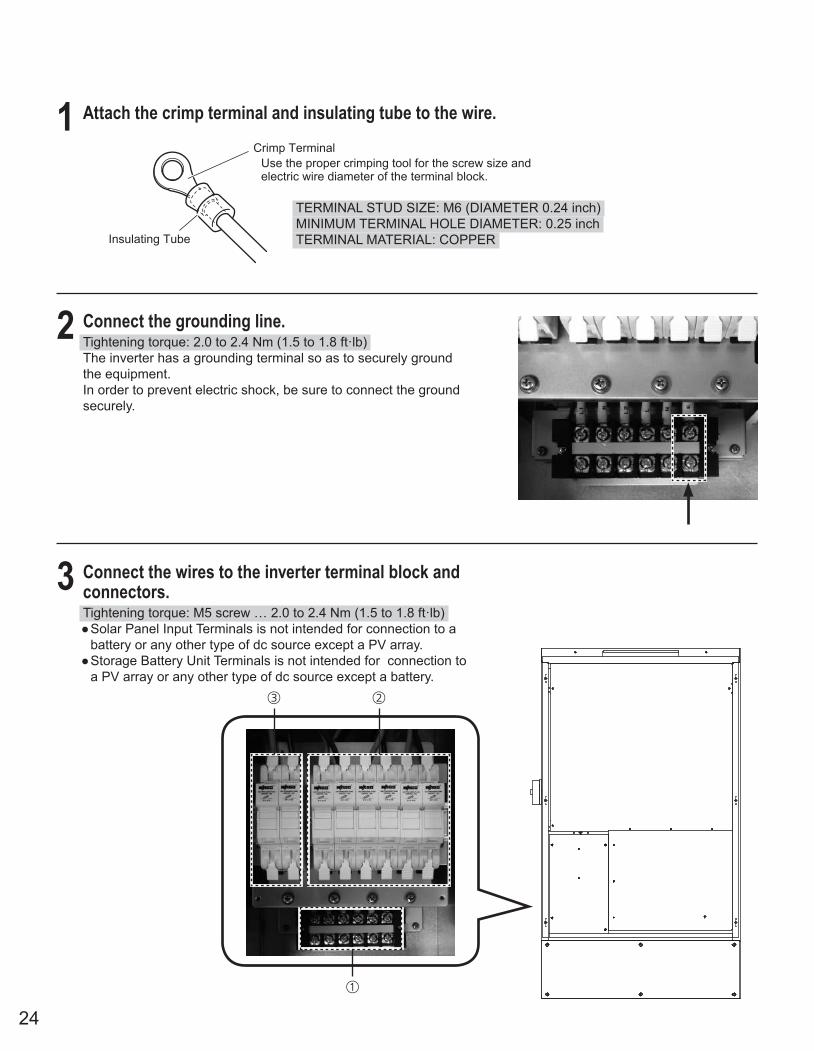
1 Attach the crimp terminal and insulating tube to the wire.
2 Connect the grounding line.Tightening torque: 2.0 to 2.4 Nm (1.5 to 1.8 ft·lb)The inverter has a grounding terminal so as to securely ground the equipment.In order to prevent electric shock, be sure to connect the ground securely.
3 Connect the wires to the inverter terminal block and connectors.Tightening torque: M5 screw … 2.0 to 2.4 Nm (1.5 to 1.8 ft·lb)● Solar Panel Input Terminals is not intended for connection to a
battery or any other type of dc source except a PV array.● Storage Battery Unit Terminals is not intended for connection to
a PV array or any other type of dc source except a battery.
Crimp Terminal
Insulating Tube
Use the proper crimping tool for the screw size and electric wire diameter of the terminal block.
TERMINAL STUD SIZE: M6 (DIAMETER 0.24 inch)MINIMUM TERMINAL HOLE DIAMETER: 0.25 inchTERMINAL MATERIAL: COPPER
②③
①

25
Solar PowerGrid-tied Breaker
Electrical Service EntranceBackup Load
Panel
L1 L NN GL2
Grid(AC) GridStand-alone
(AC)
① a. Connect the electric wires from the Solar Power Grid-tied Breaker (L1, N, L2) respectively to the grid-tied output terminals (L1, N, L2).
b. Connect the electric wires from the Backup Load Panel to the stand-alone output terminals (L, N).
c. Connect the grounding lines from the solar panel, Electrical Service Entrance, and storage battery unit.
The solar power grid-tied breakers (L1,N,L2) of the inverter are isolated from the enclosure.
Connect the groundinglines to the grounding terminals of the main screen according to the provisions of CEC.
② Peel back the sheath of the electric wires from the solar panel about 12 mm (0.47 in) and connect the wires to the solar panel input terminals (+, -).
③ Peel back the sheath of the electric wire from the storage battery unit about 12 mm (0.47 in) and connect the wires to the storage battery unit terminals (+, -).
④ Connect the signal wire from the storage battery unit to the storage battery unit connection connector, the signal cable from the Remote Controller to the Remote Controller connector, and the Current Sensor cable to the Current Sensor connector.
Storage Battery UnitTerminals
Solar Panel InputTerminals
Remote ControllerConnector
Current Sensor Connector
Storage Battery UnitSignal Connector
+ − + − + − + −

26
4 Afterwiringisinstalled,fillthewiringholewithputty.
5 Connect the Current Sensor to the Current Sensor cable
6 Connect the Current Sensor to the L1 and L2 phases so that electricity purchases and sales can be monitored and recorded.● Each cable is labeled.● The Current Sensor has L1 and L2 sides. Check the labels on the Current Sensor cable before installation.● The Current Sensor has polarity. When fitting the Current Sensor onto the electric wire, orient the Current Sensor
so that the “K” (power supply side) indication is on the side of the power meter.
CAUTIONFill the gaps around bundled wires with putty. Putty
Red & White
Black & WhiteCurrent SensorCable
Current Sensor
Back side
K : Power Supply Side
K : Power Supply Side
L: Load Side
Current Sensor
L: Load Side
L2L1
L2 HarnessL1 HarnessReversing the polarity of the Current Sensor produces incorrect measurements.
● See the Current Sensor Installation Diagram on Page 27 regarding installation.
The Current Sensor is a split core type. It can be installed after the electric wire is connected to the terminal.

27
■ Current Sensor Installation DiagramTying the inverter to the grid using a secondary feed (Example)
Current Sensor
Breaker
Solar Power Grid-tied BreakerHybrid Solar Inverter
Master Breaker
L2
L1
L1 N L2
L1
N
L2
Electrical Service Entrance
L1
N
L2
Confirm that the Current Sensor arecorrectly installed on the electric cable L1 and L2 as the labels on the Current Sensor cable.Confirm that the Current Sensor is oriented as shown the figure on Page 26.
28
HYBRID SOLAR INVERTER
N 2L1L L N GAC GRID
Stand-aloneBackup load
REMOTE CONTROLLERReverse side
Remote controller cable
SOLAR PANELS
REMOTECONTROLLER
CURRENTSENSOR
STORAGE BATTERYUNIT SIGNALCOM
DC Switch-Disconnector
MPPTfor Solar Panels
Charge/Dischargefor Storage Battery Unit
MPPTfor Solar Panels
-+
G
-+
G
-+
G
STORAGE BATTERY UNIT
B B/W
-+
G
WARNINGAll electrical installations must be made in accordance with
the local and National Electrical Code ANSI/NFPA 70 orthe Canadian Electrical Code, Part І.
L1
L2
NL N
ELECTRICAL SERVICE ENTRANCE
Backup Panel
CURRENTSENSOR
CONNECTOR
STAND ALONENEUTRAL
N
L1L2
L1L2
G
G
G
G
N
ON
OFF
ON
(Maintenance)
(Inverter)
N
N
20A
30A/2
EXISTING GROUNDINGELECTRODE
LOAD240/120V, 1
TO BACKUPLOAD
120V, 1
BACKUP LOAD PANEL
MAINTENANCESWITCH PANEL
WARNING"Stand-Alone" Neutral conductors
shall be installed in accordance withANSI/NFPA 70 200.4(A) and (B)(the National Electrical Code®)
L1
L2
N
L1
L2
L
N
N
L
N
L
N
L
NL
N
L
N
TO HOME
MPPTfor Solar Panels
-+
G
E EE
WIRING SCHEMATIC OF SINGLE PHASE SYSTEM ■ TYPICAL INSTALLATION WITH MAINTENANCE SWITCH PANEL

29
HYBRID SOLAR INVERTER
N 2L1L L N GAC GRID
Stand-aloneBackup load
REMOTE CONTROLLERReverse side
Remote controller cable
SOLAR PANELS
REMOTECONTROLLER
CURRENTSENSOR
STORAGE BATTERYUNIT SIGNALCOM
DC Switch-Disconnector
MPPTfor Solar Panels
Charge/Dischargefor Storage Battery Unit
MPPTfor Solar Panels
-+
G
-+
G
-+
G
STORAGE BATTERY UNIT
B B/W
-+
G
WARNINGAll electrical installations must be made in accordance with
the local and National Electrical Code ANSI/NFPA 70 orthe Canadian Electrical Code, Part І.
L1
L2
NL N
ELECTRICAL SERVICE ENTRANCE
Backup Panel
CURRENTSENSOR
CONNECTOR
STAND ALONENEUTRAL
N
L1L2
L1L2
G
G
G
G
N
ON
OFF
ON
(Maintenance)
(Inverter)
N
N
20A
30A/2
EXISTING GROUNDINGELECTRODE
LOAD240/120V, 1
TO BACKUPLOAD
120V, 1
BACKUP LOAD PANEL
MAINTENANCESWITCH PANEL
WARNING"Stand-Alone" Neutral conductors
shall be installed in accordance withANSI/NFPA 70 200.4(A) and (B)(the National Electrical Code®)
L1
L2
N
L1
L2
L
N
N
L
N
L
N
L
NL
N
L
N
TO HOME
MPPTfor Solar Panels
-+
G
E EE
■ TYPICAL INSTALLATION WITH MAINTENANCE SWITCH PANEL

30
HYBRID SOLAR INVERTER
N 2L1L L N GAC GRID
Stand-aloneBackup load
REMOTE CONTROLLERReverse side
Remote controller cable
SOLAR PANELS
REMOTECONTROLLER
CURRENTSENSOR
STORAGE BATTERYUNIT SIGNALCOM
DC Switch-Disconnector
Charge/Dischargefor Storage Battery Unit
-+
G
STORAGE BATTERY UNIT
B B/W
-+
G
WARNINGAll electrical installations must be made in accordance with
the local and National Electrical Code ANSI/NFPA 70 orthe Canadian Electrical Code, Part І.
L1
L2
NL N
ELECTRICAL SERVICE ENTRANCE
Backup Panel
CURRENTSENSOR
CONNECTOR
STAND ALONENEUTRAL
N
L1L2
L1L2
G
G
G
N
N
20A
30A/2
EXISTING GROUNDINGELECTRODE
LOAD240/120V, 1
TO BACKUPLOAD
120V, 1
BACKUP LOAD PANEL
L1
L2
N
L1
L2
L1
L2
N
L
N
L
N
TO HOME
TO HOMELOAD
240/120V, 1
N
WARNING"Stand-Alone" Neutral conductors
shall be installed in accordance withANSI/NFPA 70 200.4(A) and (B)(the National Electrical Code®)
MPPTfor Solar Panels
MPPTfor Solar Panels
-+
G
-+
G
MPPTfor Solar Panels
-+
G
E EE
WIRING SCHEMATIC OF SINGLE PHASE SYSTEM ■ TYPICAL INSTALLATION WITHOUT MAINTENANCE SWITCH PANEL

31
HYBRID SOLAR INVERTER
N 2L1L L N GAC GRID
Stand-aloneBackup load
REMOTE CONTROLLERReverse side
Remote controller cable
SOLAR PANELS
REMOTECONTROLLER
CURRENTSENSOR
STORAGE BATTERYUNIT SIGNALCOM
DC Switch-Disconnector
Charge/Dischargefor Storage Battery Unit
-+
G
STORAGE BATTERY UNIT
B B/W
-+
G
WARNINGAll electrical installations must be made in accordance with
the local and National Electrical Code ANSI/NFPA 70 orthe Canadian Electrical Code, Part І.
L1
L2
NL N
ELECTRICAL SERVICE ENTRANCE
Backup Panel
CURRENTSENSOR
CONNECTOR
STAND ALONENEUTRAL
N
L1L2
L1L2
G
G
G
N
N
20A
30A/2
EXISTING GROUNDINGELECTRODE
LOAD240/120V, 1
TO BACKUPLOAD
120V, 1
BACKUP LOAD PANEL
L1
L2
N
L1
L2
L1
L2
N
L
N
L
N
TO HOME
TO HOMELOAD
240/120V, 1
N
WARNING"Stand-Alone" Neutral conductors
shall be installed in accordance withANSI/NFPA 70 200.4(A) and (B)(the National Electrical Code®)
MPPTfor Solar Panels
MPPTfor Solar Panels
-+
G
-+
G
MPPTfor Solar Panels
-+
G
E EE
WIRING SCHEMATIC OF SINGLE PHASE SYSTEM ■ TYPICAL INSTALLATION WITHOUT MAINTENANCE SWITCH PANEL

32
Stand-alone Operation Check
2 Activate and check the power of the storage battery unit.① Confirm that the [+] and [-] cables are not shorted,
turn the tab to open the switch cover and set the switch inside the storage battery unit to the ON position.
② Confirm the green LED operation light on the storage battery unit is lit.
③ Confirm the voltage to the storage battery unit terminals inside the inverter is as written in the box below.Measure voltage at the test points as shown in the picture below.
1 Check wiring to the solar panels.
CAUTION Do not set the DC Switch-Disconnector on the inverter to the ON position yet.
① Confirm that there is a sufficient amount of sunlight.
② Connect the cable between the solar panels and the inverter.
③ Confirm the voltage to all solar panel input terminals is as written in the box below.Measure voltage at the test points shown in the picture on the right.
Confirm that the DC Switch-Disconnector on the outside of the inverter, the grid-tied breaker in the Electrical Service Entrance, the breakers in the Backup Load Panel, and the switch inside the storage battery unit are the OFF position. Activate power as explained in the following procedure.Supplying power to improperly connected wires will damage the inverter or storage battery unit.(Service required as a result of incorrect wiring or improper installation will be subject to billing.)
(Pay attention to polarity.)Voltage between N terminal (-) and P terminal (+): 80 to 600 V DC
● Do not short the [+] cable (black) or [-] cable (white) of the storage battery unit.
Shorted cables may damage the storage batteries and result in fire or electric shock.
WARNING
MANDATORY
(Pay attention to polarity.)Voltage between P terminal (+) and N terminal (-): 60 to 95 V DC
Test Points
OPERATE MODE ALARM②Switch Cover
Tab
Test Points

33
3 Start up the inverter.Set the DC Switch-Disconnector to the ON position.
4 Remote Controller initial settingsWhen the inverter is switched on initially, “TIME & DATE SETUP” will appear.① Set date and time and press enter by setting cursor position on “SAVE”.
② “SETTING VALUE” will appear after “SAVE”. Press “ENTER” . “SERVICE MODE 1/2” will appear.
③ Press “BACK” and back to home screen.

34
5 Confirmcommunicationbetweenthestoragebatteryunit and stand-alone operation.① Check the Remote Controller display.
“MANUAL GRID STOP” should be displayed.② Press the [RUN/STOP] button on the Remote
Controller.The button will turn red.The amount of solar power generated and the storage battery charge amount will be displayed.
The maximum amount of power charged to the storage batteries is 1.5 kW. (0 to 1.5 kW will be shown depending on the amount of sunlight). Since no loads (electric appliances) are connected to the inverter, 0.0 to 0.3 kW is shown as the difference between the solar power generated and stored power. This is the amount of output power is required to maintain the operation of the inverter.When solar power is not being generated, power is discharged from the storage batteries. On the storage battery unit, the status indicator light for the MODE will be green when charging and orange when discharging.
.
6 Check the power supply to the stand-alone input terminals (L, N).Confirm that the voltage at the stand-alone input terminals is 120 ± 6 V.
Test Points

35
7 Stop stand-alone operation.
If2ormoredaysarerequiredtoconfirmgrid-tiedoperation.● Perform steps ① to ③ and stop the system. The over-discharge prevention function of the storage battery unit may trip unless the system is stopped.※ See below. (To start grid-tied operation, restart the system.)● To check grid-tied operation now, perform steps ① to ② and proceed the “Parameters List” on page
37, without attaching the front panel of the Hybrid Solar Inverter and the front panel of the base shown on the next page.
① Press and hold the [RUN/STOP] button for 5 sec or longer to stop operation.The status lamp will go out.
② Set the DC Switch-Disconnector on the inverter to the OFF position.③ Set the switch inside the storage battery unit to the OFF position, and turn the tab to close
the switch cover.
Over-discharge prevention:The storage battery unit cannot be charged without power supplied from the commercial power grid or solar panels.If the storage batteries are not charged for 2 days or longer when the remaining charge is 0% and the storage battery unit switch automatically turns off to prevent over-discharging.If the over-discharge prevention function trips, set the switch to the ON position so as to enable charging of the storage battery.

36
Wiring Cover
Base Front Panel
8 Attach the front panel of the Hybrid Solar Inverter and the panel.Tightening Torque: 1.88 to 2.08 Nm (1.39 to 1.53 ft·lb)
① Attach the wiring cover (4 screws).
② Attach the front panel to the Hybrid Solar Inverter (6 screws).Please close by hooking the front panel to the upper body.
③ Attach the front panel to the base (6 screws).
Front Panel
Lock in place with the screws.
Hook

37
Parameters ListIEEE Parameters List
Display # Setup Item Default Parameter Range
OVDLY1 AC OvervoltageDetection Time 1 0.16 sec 0.10 / 0.13/ 0.16 sec
OVDLY2 AC OvervoltageDetection Time 2 1 sec 1 / 2 / 3 / 4 / 5 / 6 / 7 / 9 / 11 / 13 sec
UVDLY1 AC UndervoltageDetection Time 1 0.16 sec 0.10 / 0.13 / 0.16 sec
UVDLY2 AC UndervoltageDetection Time 2 1 sec 1 / 2 / 3 / 4 / 5 / 6 / 7 / 8 / 9 / 11 sec
UVDLY3 AC UndervoltageDetection Time 3 2 sec 2 / 4 / 6 / 8 / 10 / 12 / 14 / 16 / 18 / 21 sec
OFR1 AC OverfrequencyDetection Level 1 +0.5 Hz +0.0 / +0.5 / +1.0 / +1.5 / +2.0 / +2.5 /
+3.0 / +3.5 / +4.0 Hz
OFDLY1 AC OverfrequencyDetection Time 1 2 sec 2 / 5 / 10 / 20 / 50 / 100 / 150 /
200 / 250 / 300 sec
OFR2 AC OverfrequencyDetection Level 2 +2.0 Hz +0.0 / +0.5 / +1.0 / +1.5 / +2.0 /
+2.5 / +3.0 / +3.5 / +4.0 Hz
OFDLY2 AC OverfrequencyDetection Time 2 0.16 sec 0.16 / 0.5 / 1 / 1.5 / 2 / 2.5 /
4 / 6 / 8 / 10 sec
UFR1 AC UnderfrequencyDetection Time 1 -0.5 Hz -0.0 / -0.5 / -1.0 / -1.5 / -2.0 /
-2.5 / -3.0 / -3.5 / -4.0 Hz
UFDLY1 AC UnderfrequencyDetection Time 1 2 sec 2 / 5 / 10 / 20 / 50 / 100 / 150 /
200 / 250 / 300 sec
UFR2 AC UnderfrequencyDetection Level 2 -3.0 Hz -0.0 / -0.5 / -1.0 / -1.5 / -2.0 /
-2.5 / -3.0 / -3.5 / -4.0 Hz
UFDLY2 AC UnderfrequencyDetection Time 2 0.16 sec 0.16 / 0.5 / 1 / 1.5 / 2 / 2.5 /
4 / 6 / 8 / 10 sec
TIMER Power Restoration toGeneration Time 300 sec 1 / 10 / 150 / 180 / 240 / 300 sec
VOV Voltage Increase Limit 129.0 V OFF / 127.0 / 128.0 / 129.0 /130.0 / 131.0 / 132.0 V
TDH Passive ControlDetection Level 1.8 Hz 0.8 / 1.0 / 1.2 / 1.4 / 1.6 / 1.8 /
2.0 / 3.0 / 4.0 / 5.0 Hz
VOVL Voltage IncreaseLimit Level 0 % 0 / 50 %
PF Power Factor +1.00
+0.80 / +0.81 / +0.82 / +0.83 / +0.84 /+0.85 / +0.86 / +0.87 / +0.88 / +0.89 /+0.90 / +0.91 / +0.92 / +0.93 / +0.94 /+0.95 / +0.96 / +0.97 / +0.98 / +0.99 /+1.00 / -0.80 / -0.81 / -0.82 / -0.83 / -0.84 / -0.85 / -0.86 / -0.87 / -0.88 / -0.89 / -0.90 / -0.91 / -0.92 / -0.93 / -0.94 / -0.95 / -0.96 / -0.97 / -0.98 / -0.99
SAVOLT Stand Alone Voltage 120 V 120 / 240 V
* SAVOLT is fixed “120 V”. Should not select “240 V”.

38
■ Fixed value List
Display # Setup Item Default (Fixed)
OVR1 AC Overvoltage Detection Level 1 288 V
OVR2 AC Overvoltage Detection Level 2 264 V
UVR1 AC Undervoltage Detection Level 1 108 V
UVR2 AC Undervoltage Detection Level 2 144 V
UVR3 AC Undervoltage Detection Level 3 211.2 V
HECO Parameters List
Display # Setup Item Default Parameter Range
UVDLY2 AC UndervoltageDetection Time 2 16 sec 11 / 12 / 13 / 14 / 15 / 16 / 17 /
18 / 19 / 20 / 21 sec
TIMER Power Restoration toGeneration Time 300 sec 10 / 300 / 360 / 420 / 480 /
540 / 600 sec
VOV Voltage Increase Limit 129.0 V OFF / 127.0 / 128.0 / 129.0 /130.0 / 131.0 / 132.0 V
TDH Passive ControlDetection Level 1.8 Hz 0.8 / 1.0 / 1.2 / 1.4 / 1.6 / 1.8 /
2.0 / 3.0 / 4.0 / 5.0 Hz
VOVL Voltage IncreaseLimit Level 0 % 0 / 50 %
PF Power Factor +1.00
+0.80 / +0.81 / +0.82 / +0.83 / +0.84 /+0.85 / +0.86 / +0.87 / +0.88 / +0.89 /+0.90 / +0.91 / +0.92 / +0.93 / +0.94 /+0.95 / +0.96 / +0.97 / +0.98 / +0.99 /+1.00 / -0.80 / -0.81 / -0.82 / -0.83 / -0.84 / -0.85 / -0.86 / -0.87 / -0.88 / -0.89 / -0.90 / -0.91 / -0.92 / -0.93 / -0.94 / -0.95 / -0.96 / -0.97 / -0.98 / -0.99
SAVOLT Stand Alone Voltage 120 V 120 / 240 V
* SAVOLT is fixed “120 V”. Should not select “240 V”.

39
Parameter SettingTo change the initial parameter settings, go through the following steps.The adjustment of the setting requires approval from the authority having jurisdiction.
1 Restart the system if the system is not running.① See Page 17 and remove the front panel of the Hybrid Solar Inverter and the base. Confirm that the solar panel switch on the outside of the inverter is in the OFF position.② Open the switch cover on the storage battery unit and set the switch to the ON position.③ Set the Solar Power grid-tied breaker to the ON position.
(When the inverter is tied to the grid through a secondary feed, set the Master breaker to the ON position, as well.)Confirm that the terminal voltage of the Solar Power grid-tied breaker and Master breaker is 120/240 V.
2 Set the Remote Controller to the Service Mode.① From the Home Screen, confirm that stand-alone and
grid-tied operation are manually stopped.② Press and hold the [SETUP] and [RECORD] buttons
for 5 seconds or more to enter the Service Mode.③ Caution Message is displayed, press [ENTER].
Press and hold both buttons for 5 seconds or more.
3 Set parameters.① From the SERVICE MODE 1/2 screen, select
“SETTING VALUE” and press [ENTER].
② Press [↓], select “IEEE” or “HECO”, and then press [ENTER].
Press [ENTER] to display “IEEE” or “HECO” under subsequent settings screens.

40
③ Confirm the “SETTING VALUE FOR INVERTER 1” is selected and press [ENTER].
④ The parameter menu will appear. (See Page 37 for a description of the parameters in the parameter menu.)
Scroll through the parameter menu using the [↓] button. To select a parameter, press the [ENTER] button.
⑤ Press [CHANGE] to change the value to the desired value.
IEEE HECO
IEEE HECO
IEEE HECO

41
⑥ Press [ENTER] to return to the parameter menu. Repeat Steps ③ to ⑤ to change other parameters.
⑦ When all parameters changes are complete, select “SAVE” and press [ENTER].
⑧ Settings are entered and a confirmation screen will appear. To return to the Home Screen, press [BACK] three times.
IEEE HECO
IEEE HECO
42
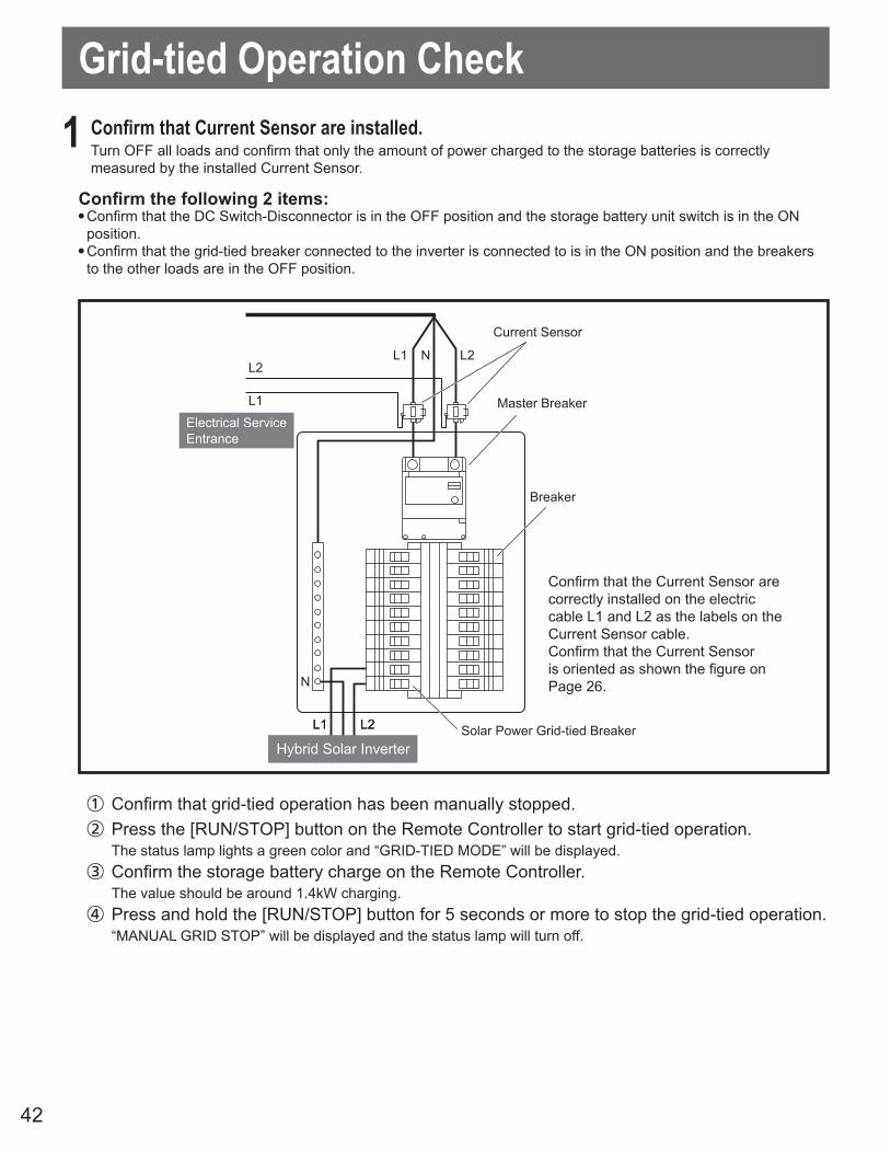
Grid-tied Operation Check
Current Sensor
Breaker
Solar Power Grid-tied BreakerHybrid Solar Inverter
Master Breaker
L2
L1
L1 N L2
L1
N
L2
Electrical Service Entrance
L1
N
L2
Confirm that the Current Sensor arecorrectly installed on the electric cable L1 and L2 as the labels on the Current Sensor cable.Confirm that the Current Sensor is oriented as shown the figure on Page 26.
1 ConfirmthatCurrentSensorareinstalled.Turn OFF all loads and confirm that only the amount of power charged to the storage batteries is correctly measured by the installed Current Sensor.
Confirm the following 2 items:● Confirm that the DC Switch-Disconnector is in the OFF position and the storage battery unit switch is in the ON
position. ● Confirm that the grid-tied breaker connected to the inverter is connected to is in the ON position and the breakers
to the other loads are in the OFF position.
① Confirm that grid-tied operation has been manually stopped.② Press the [RUN/STOP] button on the Remote Controller to start grid-tied operation.
The status lamp lights a green color and “GRID-TIED MODE” will be displayed.③ Confirm the storage battery charge on the Remote Controller.
The value should be around 1.4kW charging.④ Press and hold the [RUN/STOP] button for 5 seconds or more to stop the grid-tied operation.
“MANUAL GRID STOP” will be displayed and the status lamp will turn off.
43
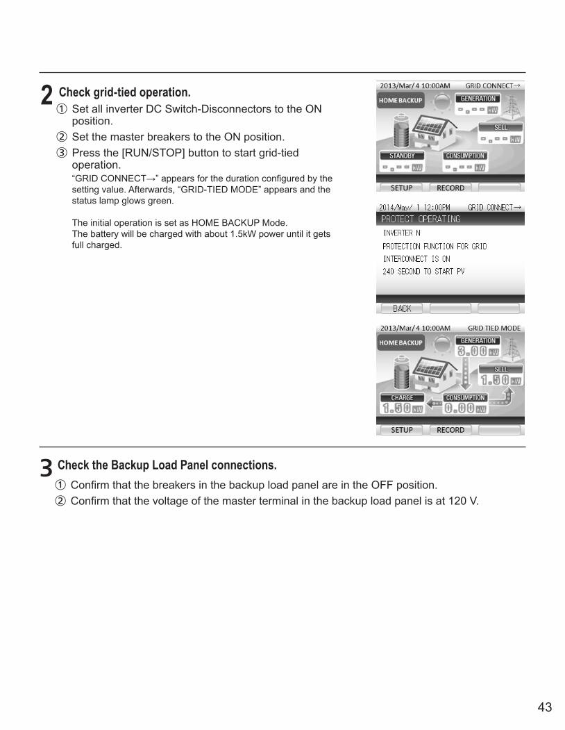
2 Check grid-tied operation.① Set all inverter DC Switch-Disconnectors to the ON
position.② Set the master breakers to the ON position.③ Press the [RUN/STOP] button to start grid-tied
operation.“GRID CONNECT→” appears for the duration configured by the setting value. Afterwards, “GRID-TIED MODE” appears and the status lamp glows green.
The initial operation is set as HOME BACKUP Mode.The battery will be charged with about 1.5kW power until it gets full charged.
3 Check the Backup Load Panel connections.① Confirm that the breakers in the backup load panel are in the OFF position.② Confirm that the voltage of the master terminal in the backup load panel is at 120 V.

44
■ System Shutdown① Set the DC Switch-Disconnector on the outside of the inverter, the switch inside the storage
battery unit and the solar power grid-tied breaker in the Electrical Service Entrance to the OFF position.
② Attach the front panels to the Hybrid Solar Inverter and base, and turn the tab of the storage battery unit to close the switch cover.
■ System Startup③ Turn the tab of the storage battery unit to open the switch cover and set the storage battery
unit switch to the ON position.④ Set the solar power grid-tied breaker in the Electrical Service Entrance to the ON position.⑤ Detach the front panel from the Hybrid Solar Inverter and set the DC Switch-Disconnector to
the ON position.■ Configuring the Connection to the Internet
Refer to User ‘s Manual and configure the connection to the internet.
4Confirmthatthepowerrecoveryisactiveduringapoweroutage.① Set both the master breaker and the solar power grid-tied breaker in the Electrical Service
Entrance to the OFF position. The power outage error code “gxxx” should be displayed on the Remote Controller.
② About 5 seconds after Step ① is performed, stand-alone operation starts.“STAND-ALONE MODE” should be displayed and the status lamp will turn red.
③ Set both the master breaker and the grid-tied breaker in the Electrical Service Entrance to the ON position.
④ “GRID CONNECT→” should appear after step ③ has been performed. The display changes to “GRID TIED MODE” after the time configured by the setting value elapses.
⑤ Press and hold the [RUN/STOP] button on the Remote Controller for 5 sec or more to stop the grid-tied operation.“MANUAL GRID STOP” should be displayed and the status lamp will turn off.
When it takes 2 days or more for equipment to be delivered to a customer(Grid-tied operation starts)
● Perform Steps ① to ② below to stop the system. Perform steps ③ to ⑤ at the time of delivery to restart the system.
(The storage battery over-discharge prevention function of the storage battery unit may trip unless the system is stopped.)
● After work is completed, reattach the front panels and the switch cover, and start grid-tied operation as explained in the User’s Manual.

45
TroubleshootingError Message (Troubleshooting) Error Code
DETECTEDABNORMALITYINSIDEINVERTER.PLEASECONTACTTHESERVICECENTER.
D015,D025,D035,B103-B104,B106,T001,T003,T004,T006
DETECTEDABNORMALITY INSIDE INVERTER.PLEASECONTACTTHESERVICECENTERIFTHEERRORMESSAGECONTINUESMORETHAN5MINUTES.
b101,b109-b110,E001,E012,E014,E016,E019,E020,e001,e012,e014,e016 -e020,e024,e025
POWERCONSUMPTIONONTHEAPPLIANCESCONNECTEDTOSTANDALONEOUTLET EXCEEDSMAXIMUMPOWER LIMIT.PLEASEREDUCEPOWERCONSUMPTIONBYDISCONNECTINGSOMEDEVICES.
e009-e011
INVERTERTEMPERATURE ISOUTOFRANGE.PLEASECHECKITSSURROUNDING.PLEASECONTACTTHESERVICECENTER IFTHEERRORMESSAGESTAYSON.
d013,d023,d033,E003,e003
GRIDABNORMALITYDETECTED.WILLRESTARTIN5MIN.ONCEGRIDISBACKNORMAL.PLEASECONTACTTHESERVICECENTERIFTHEERRORMESSAGECONTINUESMORETHAN5MIN.
g001-g005,g008-g009
INSUFFICIENTSUNLIGHTORLOWBATTERYVOLTAGES. n001,n004
PVVOLTAGEISHIGH.PLEASECONTACTTHESERVICECENTERIFTHEERRORMESSAGECONTINUES. d011,d021,d031
PLEASECONTACTTHESERVICECENTERIFTHISERRORMESSAGECONTINUES.
b103,D011,D013,D021,D023,D031,D033,e008,e026,U026,M055, t006,t007,T007
BATTERYABNORMALITYDETECTED. PLEASECONTACT THESERVICECENTER.
M034,M037,M039,M041,M043,M044,M046,M047,M049 -M054,M057,M065-M068,M071,M099,M129-M132,M137,M138
GRIDABNORMALITYDETECTED.PLEASECONTACTTHESERVICECENTER IF THEERRORMESSAGECONTINUESMORETHAN5MINUTES.
E004,E006,E007,e004,e006,e007
INVERTERFAULTDETECTED.PLEASECONTACTTHESERVICECENTERIFTHEERRORMESSAGECONTINUESMORETHAN5MIN. r-04
INVERTERCANNOTSTART.RESTARTINVERTERWHENSUNLIGHTRETURNSTONORMAL.PLEASECONTACTTHESERVICECENTERIFINVERTERCANNOTSTARTDURINGNORMALSUNLIGHT.
r-16,r-18
PETRIEVINGIPADDRESSFAILED.PLEASECONFIRMCONNECTIONANDPRESS“RETRY”KEY. r-10
STORAGEBATTERYFAULTDETECTED.PLEASECONTACTTHESERVICECENTER IFTHEERRORMESSAGEDOESN'TDISAPPEARAFTER5MIN.
m033,m036,m038,m040,m042,m045,m097,m098

46
Error Message (Troubleshooting) Error Code
REMOTECONTROLLERISNOTWORKINGPROPERLY.PLEASECONTACTTHESERVICECENTER. R-02,R-03
IFOPERATIONMODECANNOTBESYNCHRONIZEDAFTERRESTARTINGBYRUN/STOPBUTTONMANUALLY,PLEASECONTACTTHESERVICECENTER.
r-14
DATACOPYFAILED. r-15
INSULATION/GROUNDFAULTDETECTED.CONTACTTHESERVICECENTER. T008*
INSULATIONTESTFAILED.PLEASECONTACTTHESERVICECENTER. T009
ARCTESTFAILED.PLEASECONTACTTHESERVICECENTER. T010
ELECTRICSHOCKHAZARDARCFAULTDETECTED.CONTACTTHESERVICECETER. U023
ISOLATIONTESTNOWPLEASEWAITAMOMENT. u030
THEBATTERYSTOPPEDDUETOITSENDOFLIFE.PLEASECONTACTTHESERVICECENTER. M058
THEBATTERYWILLSOONREACHITSENDOFLIFE.PLEASECONTACTTHESERVICECENTER. m145
ISOLATION FAULTDETECTED.PLEASECONTACTTHECENTER. e027,e028,e029,e030
* WARNING: WHEN A GROUND FAULT IS INDICATED, NORMALLY UNGROUNDED CONDUCTORS MAY BE GROUNDED. BATTERY TERMINALS AND CONNECTED CIRCUITS MIGHT BE UNGROUNDED AND HAZARDOUS. Check the PV system for ground faults.

47
Checking the PV System for Ground FaultsIf the Error Code “T008” is displayed in the remote controller, this could indicate a ground fault. The electrical insulation from the PV system to the ground is defective or insufficient.
DANGERRisk of death or serious injury due to electric shock.In the event of a ground fault, high voltage levels can be present.● Touch the cables of the PV array on the insulation only.● Do not touch any parts of the board or frame of the PV array.● Do not connect PV strings with ground faults to the inverter.
WARNINGDestruction of measuring device due to overvoltage● Only use measuring devices with a DC input voltage range up to 1,000 V.
Proceed as following to check each string in the PV system for ground faults.
Procedure:1. DANGER Risk of death or serious injury due to electric shock.
● Disconnect the inverter from all voltage sources.2. Measure the voltages at the DC terminal:
● Measure the voltages between the positive terminal and the ground potential.● Measure the voltages between the negative terminal and the ground potential.● Measure the voltages between the positive and negative terminals.
If the following results are present at the same time, there is a ground fault in the PV system.- All measured voltages are stable.- The sum of the two voltages to the ground potential is approximately equal to the voltage between the
positive and negative terminals.- Determine the location of the ground fault via the ratio of the measured voltages.- Eliminate the ground fault.
If there is no ground fault and the message is still displayed, contact the TABUCHI ELECTRIC Service Line.
*The voltages between Storage Battery Unit terminals: 60 - 95 V
Disconnecting the Inverter from Voltage SourcesPrior to performing any work on the inverter, always disconnect it from all voltage sources as described in this section.
1. DANGER Risk of death or serious injury due to electric shock.● Disconnect the inverter from the utility grid and confirm that it cannot be reconnected.● Disconnect the inverter from the PV array and confirm that it cannot be reconnected.● Disconnect the inverter from the storage battery unit and confirm that it cannot be reconnected.
2. Wait 5 minutes after disconnecting the inverter from the utility grid, the PV array and the storage battery unit.
3. Remove the 6 screws from the front panel.
4. Remove the front panel.
5. Use a suitable measuring device to confirm that no voltage is present at the DC terminals.
6. Use a suitable measuring device to confirm that no voltage is present at the AC terminals.

48
SpecificationsItem Specifications
Storage Battery Input / Output
Rated charging maximum continuous output current DC 16.5 A
Maximum charge / discharge current DC 26 A
Nominal output voltage DC 86.4 V
Number of input circuit 1 circuit
Charging output voltage operation range DC 60 - 95 V
Solar Input
Range of input operating voltage DC 80 - 550 V
Maximum input current 12 A
Maximum (open circuit) photovoltaic input voltage DC 600 V
Maximum photovoltaic input short-circuit under any condition 15 A
Number of input circuit 3 circuit
Input voltage range per circuit DC 80 to 240 V: 1000 W to 2500 W DC 240 to 550 V: 2500 W
Array configuration ungrounded
Grid Input / Output
Nominal output voltage AC 240 V
Electrical connection Single Phase (Split Phase)
Connection Method 3-wire
Operating voltage range AC 211.2 - 262 V
Rated AC input current AC 23.4 A
Maximum continuous output current AC 22.9 A
Maximum continuous output power AC 5500 W
Nominal output frequency 60 Hz
Efficiency Max. 95.5% / CEC 94.8%
Output power factor ≥ 0.95
Distortion rate of the output current
Total: less than 5%Each of the following:h<11: less than 4.0%
11≤h<17: less than 2.0%17≤h<23: less than 1.5%23≤h<35: less than 0.6%
35≤h: less than 0.3%*The even stage is to be 25% of the odd stage range.
Stand-alone Output
Nominal output voltage AC 120 V
Operating voltage range AC 114 - 126 V
Electrical Connection Single Phase 2-Wire
Maximum continuous output power AC 2000 VA
Noise Emission ≤ 41 dB
Operating Temperature -20 to +40°C (-4 to +104°F)
Operating Humidity ≤ 90% (Non-condensing)
Weight (Including base) Approx. 68 kg (149.9 lb)
Dimensions (Including base) W 680 × H 1200 × D 250 mm (26.8 × 47.2 × 9.8 in)

49
Arc Fault Circuit ProtectionThe inverter is certified to UL1699B.It has protection circuit for arc fault caused by photovoltaics.

50
FCC Compliance
This equipment has been tested and found to comply with the limits for a Class B digital device, pursuant to part 15 of the FCC Rules. These limits are designed to provide reasonable protection against harmful interference when the equipment is operated in a residential installation. This equipment generates, uses, and can radiate radio frequency energy and, if not installed and used in accordance with the instruction manual, may cause harmful interference to radio communications. Operation of this equipment in a residential area is likely to cause harmful interference in which case the user will be required to correct the interference at his own expense.
Notes

MEMO
51

Tabuchi Electric Co., Ltd. DOC02-DS1613-AJ