Doc. N.° 1SDH000789R0005 - B1319 SACE Tmax T7D/PV - … · Doc. N.° 1SDH000789R0005 - B1319 SACE...
8
B A Doc. N.° 1SDH000789R0005 - B1319 SACE Tmax T7D/PV - T7D/PV-E Istruzioni di installazione Tmax T7D/PV - T7D/PV-E Tmax T7D/PV - T7D/PV-E Installation instructions Installationsanleitung Tmax T7D/PV - T7D/PV-E Instructions pour l'installation Tmax T7D/PV - T7D/PV-E Instrucciones de instalación Tmax T7D/PV - T7D/PV-E 200 T7D/PV (UP TO 1100V) T7D/PV-E (UP TO 1500V) 1,2 Nm 2,5 Nm
Transcript of Doc. N.° 1SDH000789R0005 - B1319 SACE Tmax T7D/PV - … · Doc. N.° 1SDH000789R0005 - B1319 SACE...

B
A
Doc. N.° 1SDH000789R0005 - B1319
SACE Tmax T7D/PV - T7D/PV-E
Istruzioni di installazione Tmax T7D/PV - T7D/PV-ETmax T7D/PV - T7D/PV-EInstallation instructions
Installationsanleitung Tmax T7D/PV - T7D/PV-EInstructions pour l'installation Tmax T7D/PV - T7D/PV-EInstrucciones de instalación Tmax T7D/PV - T7D/PV-E
200
T7D/PV(UP TO 1100V)
T7D/PV-E(UP TO 1500V)
1,2 Nm
2,5 Nm

C
Tmax T7D/PV | ABB
D
T7D/PV - T7D/PV-E
WITH FLANGECON MOSTRINA
WITHOUT FLANGESENZAMOSTRINA
103
206
208
XX
Y
Y
26315
1
4Ø
245
140
226
241= =
= =
ø5.5 (M5)35
289
= =
= =
XX
Y
Y
Y
Y
X
X
Example for 1600A
2CABLE SECTION: 4x240mm
350
230
200
250
165 165XX
Y
Y
See fig. G
350
230
165 165XX
Y
200

E
T7D/PV-E
Tmax T7D/PV | ABB
F
TERMINAL 1
TERMINAL 2
Nessuna prova dielettrica tra i terminali 1 e 2No dielectric tests between terminals 1 and 2Keine Isolationsprüfungen zwischen den Terminals 1 und 2Pas de tests diélectriques entre les terminaux 1 et 2No hay pruebas dieléctricas entre los terminales 1 y 2
Opening through SOR/UVR.WARNING: Opening through lever for emergency use onlyApertura mediante SOR/UVR. ATTENZIONE: Apertura mediante leva solo in caso di emergenzaAusschaltung durch SOR/UVR. ACHTUNG: Ausschaltung durch hebel nur im Fall einer NotfallOuverture par SOR/UVR.ATTENTION: Ouverture par levier seulement en cas d'urgenceDisparo mediante SOR/UVR.ATENCIÓN: Disparo mediante palanca sólo en caso de emergencia
TRIPPED
CLACK
ONOFF
T7D/PV - T7D/PV-E
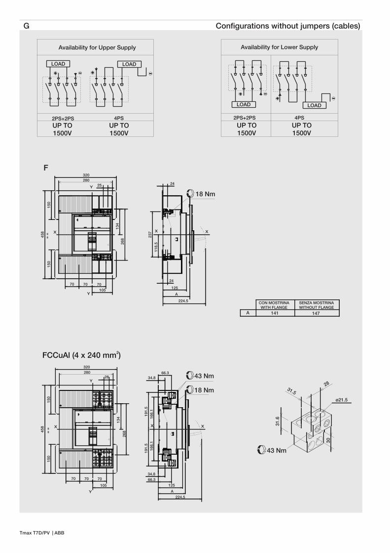
G Configurations without jumpers (cables)
A 141 147
CON MOSTRINAWITH FLANGE
SENZA MOSTRINAWITHOUT FLANGE
2PS+2PS
LOAD LOAD
4PS
Availability for Lower Supply
UP TO1500V
UP TO1500V
31.6
31.528
30
43 Nm
ø21.5
268
134
150
150
458
70 70 70
105
28
320
= =
2FCCuAl (4 x 240 mm )
X
Y
Y
280
24
24
125
A
224.5
118.
5
237 XX
18 Nm
F
268
134
150
28025
70 70 70105
320
458
150
= =
X
Y
Y
LOAD
2PS+2PS
LOAD
4PS
Availability for Upper Supply
UP TO1500V
UP TO1500V
Tmax T7D/PV | ABB
166.
119
1.5
166.
119
1.5
125
A
224.5
34.8
34.8
66.3
66.3
XX
18 Nm
43 Nm

J
H I
In configurazione senza Jumpers usare cavi ed eseguire prove di tipo specifiche sull'installazione.
For configuration without Jumpers use cable and perform specific type test on the installation.
Per configurazioni di cablaggio diverse da quelle di seguito rappresentate eseguire prove di tipo specifiche sull'installazione e usare connessioni isolate.
For different wiring configurations than those shown afterwards perform specific type test on the installation and use insulated terminals connection.
LOAD
0NQ) 0NQ
UPPER SUPPLY
EF FCCuAl F F FCCuAl EF
1100 V 1100 V
1500 V 1500 V
1250 A 1600 A
2PS+2PS
LOWER SUPPLY
VR HR ES EF FCCuAl F F FCCuAl EF ES HR VR
1100 V 1100 V
1500 V 1500 V
1600 A1250 A
LOAD
2NQ
LOWER SUPPLY
ES EF FCCuAl F F FCCuAl EF ES
1100 V 1100 V
1500 V 1500 V
1250 A 1600 A
LOAD
2NQ
UPPER SUPPLY
EF F F EF
1100 V 1100 V
1500 V 1500 V
1250 A 1600 A
LOAD
Configurations with jumpers (possible solutions)
Tmax T7D/PV | ABB

K Configurations with jumpers
3
1
2
18 Nm
1
2
3
18 Nm
Example with jumper for 1250A(4PS Lower Supply)
Example withjumper for 1600A(4PS Lower Supply)
Tmax T7D/PV | ABB

L 2PS+2PS solution
FC Cu Al2(4 x 240 mm )
191
291.
5
210
28
34.8
66.3
XX
18 Nm
90
45
1540.5
ø13
XX
24 70
125
A
224.5
25
44
15
29.5 ø11
31.5
28
43 Nm
ø21.5
278
258
348
== =
XX
18 Nm
480
199.
5
173
210
XX
18 Nm
480
LOAD
A 141 147
CON MOSTRINAWITH FLANGE
SENZA MOSTRINAWITHOUT FLANGE
268
134
70 105
230
230
123 =
=
200
205
480
210= = =
111
X
X
25
44
15
ø11
* UPPER SUPPLY - According to scheme L, terminals configurations must be symmetrical respect to x-x CB axis
2PS+2PSUPPERSUPPLY
VR
F
EF
2PS+2PSLOWERSUPPLY
LOAD
ES
210= = =
111
X
X
25
44
15
ø11
HR
LOWER SUPPLY
Tmax T7D/PV | ABB
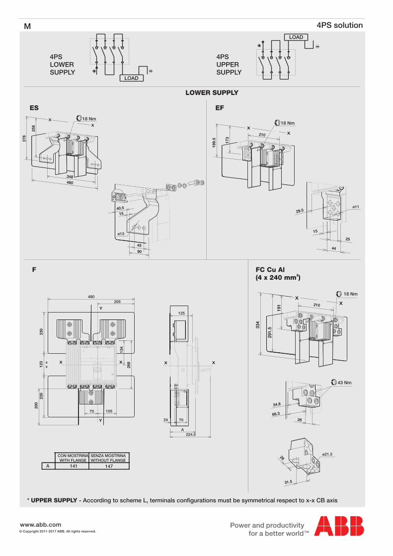
M 4PS solution
www.abb.com© Copyright 2011-2017 ABB. All rights reserved.
LOAD
90
45
1540.5
ø13
278
258
X
X
18 Nm
480
348
199.
5
173
XX
18 Nm
210
191
291.
5334
XX
18 Nm
210
43 Nm
28
34.8
66.3
25
44
15
29.5ø11
28
31.5
ø21.5
FC Cu Al2(4 x 240 mm )
A 141 147
CON MOSTRINAWITH FLANGE
SENZA MOSTRINAWITHOUT FLANGE
24 70
125
A224.5
X X
268
134
X
70 105
X
Y
Y
230
230
123 =
=
200
205480
LOAD
4PSUPPERSUPPLY
F
EFES
4PSLOWERSUPPLY
* UPPER SUPPLY - According to scheme L, terminals configurations must be symmetrical respect to x-x CB axis
LOWER SUPPLY