getting to grips with RNP AR Required Navigation Performance with ...

Manual on
Required Navigation
Performance (RNP)
(Doc 9613-AN/937)
SECOND EDITION — 1999

AMENDMENTS
The issue of amendments is announced regularly in the ICAO Journal and in themonthly Supplement to the Catalogue of ICAO Publications and Audio-visualTraining Aids, which holders of this publication should consult. The space belowis provided to keep a record of such amendments.
RECORD OF AMENDMENTS AND CORRIGENDA
AMENDMENTS CORRIGENDA
No.Date
applicableDate
enteredEntered
by No.Date
of issueDate
enteredEntered
by
(ii)

Table of Contents
Page Page
Chapter 1. Introduction . . . . . . . . . . . . . . . . . . . . 1
1.1 General. . . . . . . . . . . . . . . . . . . . . . . . . . . . . 11.2 Purpose of manual . . . . . . . . . . . . . . . . . . . . 11.3 Explanation of terms . . . . . . . . . . . . . . . . . . 1
Chapter 2. Concept and application of required navigation performance . . . . . . . . . . . . . . 3
2.1 General. . . . . . . . . . . . . . . . . . . . . . . . . . . . . 32.2 RNAV operations within the
RNP concept . . . . . . . . . . . . . . . . . . . . . . . . 32.3 Airspace use. . . . . . . . . . . . . . . . . . . . . . . . . 42.4 Aircraft performance . . . . . . . . . . . . . . . . . . 52.5 RNP service provisions . . . . . . . . . . . . . . . . 5
Chapter 3. General provisions of required navigation performance . . . . . . . . . . . . . . 6
3.1 General. . . . . . . . . . . . . . . . . . . . . . . . . . . . . 63.2 Elements of RNP containment . . . . . . . . . . 63.3 RNP types . . . . . . . . . . . . . . . . . . . . . . . . . . 7
Chapter 4. Airspace requirements. . . . . . . . . . . . 9
4.1 Airspace where RNP applies. . . . . . . . . . . . 94.2 Airspace characteristics . . . . . . . . . . . . . . . . 94.3 Airspace requirements . . . . . . . . . . . . . . . . . 10
Chapter 5. Aircraft requirements . . . . . . . . . . . . 12
5.1 General. . . . . . . . . . . . . . . . . . . . . . . . . . . . . 125.2 Functional requirements . . . . . . . . . . . . . . . 135.3 System performance . . . . . . . . . . . . . . . . . . 145.4 System design, construction and
installation . . . . . . . . . . . . . . . . . . . . . . . . . . 205.5 Airworthiness approval of RNAV/FMS
equipment . . . . . . . . . . . . . . . . . . . . . . . . . . 205.6 Operational approval of RNAV/FMS
equipment . . . . . . . . . . . . . . . . . . . . . . . . . . 215.7 Reference documents . . . . . . . . . . . . . . . . . 22
Chapter 6. Required navigation performance operations . . . . . . . . . . . . . . . . . . . . . . 23
6.1 Provision of navigation services . . . . . . . . . 236.2 Training requirements . . . . . . . . . . . . . . . . . 256.3 Special radiotelephony procedures
for RNP operations . . . . . . . . . . . . . . . . . . . 26
APPENDIX A. Explanation of terms . . . . . . . . . . . 27
APPENDIX B. Rationale for the choice of RNP values. . . . . . . . . . . . . . . . . . . . . . . . . . . . . . . 30
APPENDIX C. Estimating navigation performance accuracy. . . . . . . . . . . . . . . . . . . . . . . . . 34
APPENDIX D. Reference documentationrelated to area navigation . . . . . . . . . . . . . . . . . . . . . . 40

bytialicot
nentldnted
aftanP 1ayvelire-theet the.g.ing-
ainPvident
uce
onms
Chapter 1
INTRODUCTION
1.1 GENERAL
1.1.1 The Special Committee on Future AirNavigation Systems (FANS) identified that the methodmost commonly used over the years to indicate requirednavigation capability was to prescribe mandatory carriageof certain equipment. This constrained the optimumapplication of modern airborne equipment. Also, withsatellites becoming available, this method would impose alaborious selection process by the International CivilAviation Organization. To overcome these problems, thecommittee developed the concept of required navigationperformance capability (RNPC). FANS defined RNPC as aparameter describing lateral deviations from assigned orselected track as well as along track position fixingaccuracy on the basis of an appropriate containment level.Although this concept avoids the need for ICAO selectionbetween competing systems from the beginning, it does notprevent ICAO from dealing with navigation techniques thatare in use internationally. The RNPC concept was approvedby the ICAO Council and was assigned to the Review of theGeneral Concept of Separation Panel (RGCSP) for furtherelaboration. The RGCSP, in 1990, noting that capabilityand performance were distinctively different and thatairspace planning is dependent on measured performancerather than designed-in capability, changed RNPC torequired navigation performance (RNP).
1.1.2 The RGCSP then developed the concept of RNPfurther by expanding it to be a statement of the navigationperformance accuracy necessary for operation within adefined airspace. A specified type of RNP is intended todefine the navigation performance of the population ofusers within the airspace commensurate with the navigationcapability within the airspace. RNP types are identified bya single accuracy value as envisaged by FANS.
1.1.3 System use accuracy is based on the combinationof the navigation sensor error, airborne receiver error,display error and flight technical error. This combination isalso known as navigation performance accuracy.
1.1.4 The RNP types specify the navigationperformance accuracy of all the user and navigation system
combinations within an airspace. RNP types can be usedairspace planners to determine airspace utilization potenand as an input in defining route widths and traffseparation requirements, although RNP by itself is nsufficient basis for setting a separation standard.
1.1.5 RNP types specify the minimum navigatioperformance accuracy required in an airspace. It is evidthat an aircraft with a less accurate type of RNP wounormally be excluded from airspace with more stringerequirements or, alternatively, may be allocated increasseparation minima. If appropriately equipped, an aircrwith a level of navigation performance more accurate ththat specified can fly in the airspace concerned (e.g. RNcertified aircraft operating in RNP 4 airspace). There mbe occasions, however, when for example an aircraft’s leof navigation performance accuracy may meet the requment of a more stringent RNP airspace, based on navigation aid (navaid) infrastructure, but might not methe requirements of a less stringent RNP airspace due tolack of aids appropriate to its navigation equipment fit, eRNP 1 certified aircraft based on dual distance measurequipment (DME), may not be fitted with appropriate longrange aids to enable operation in RNP 12.6 airspace.
1.2 PURPOSE OF MANUAL
The basic purpose of this guidance material is to explthe concept and provisions of RNP, identify how RNaffects the system providers and system users, and proregional planning groups with a basis for the developmeof documents, procedures and programmes to introdRNP into the airspace. This manual supersedes the Manualof Area Navigation (RNAV) Operations (Doc 9573) andcontains all relevant material from that document.
1.3 EXPLANATION OF TERMS
1.3.1 Development and explanation of RNP relies the understanding of some particular terms. These terhave the following meanings:
1
2 Manual on Required Navigation Performance (RNP)
e
r,alr,r.i-
ted
Area navigation (RNAV). A method of navigation thatpermits aircraft operation on any desired flight path.
Navigation performance accuracy. The total system error(TSE) allowed in the individual lateral and longitudinaldimensions. TSE in each dimension must not exceedthe specified RNP type for 95 per cent of the flight timeon any portion of any single flight.
Required navigation performance (RNP). A statement ofthe navigation performance necessary for operationwithin a defined airspace. Navigation performance and
requirements are defined for a particular RNP typand/or application.
Total system error. In the lateral dimension, a combinationof navigation system error, RNAV computation errodisplay system error and FTE. In the longitudindimension, a combination of navigation system erroRNAV computation error, and display system erro(See section 3.2 and Appendix C (Estimating Navgation Performance Accuracy)).
1.3.2 Explanations of these and other terms associawith airborne navigation are included in Appendix A.

inVberialAVantoeiras
de-Pureedhee-
ftas air
lya
areay-gtal
cy beAbe
tcyd-
Chapter 2
CONCEPT AND APPLICATION OFREQUIRED NAVIGATION PERFORMANCE
2.1 GENERAL
2.1.1 The continuing growth of aviation placesincreasing demands on airspace capacity and emphasizesthe need for the optimum utilization of the availableairspace. These factors, allied with the requirement foroperational efficiency in terms of direct routings and track-keeping accuracy, together with the enhanced accuracy ofcurrent navigation systems, have resulted in the concept ofRNP.
2.1.2 RNP as a concept applies to navigationperformance within an airspace and therefore affects boththe airspace and the aircraft. RNP is intended tocharacterize an airspace through a statement of thenavigation performance accuracy (RNP type) to beachieved within the airspace. The RNP type is based on anavigation performance accuracy value that is expected tobe achieved at least 95 per cent of the time by thepopulation of aircraft operating within the airspace.
2.1.3 The development of the RNP conceptrecognizes that current aircraft navigation systems arecapable of achieving a predictable level of navigationperformance accuracy and that a more efficient use ofavailable airspace can be realized on the basis of thisnavigation capability.
2.1.4 Several factors may affect States’ decisions as towhich approval type (e.g. RNP 1, RNP 4) will be requiredalong various air traffic services (ATS) routes for particularprocedures, or in various areas. Area navigation (RNAV)equipment approval should address protected airspacewhere separation is predicated on ATS route widths.
2.1.5 Other types of navigation (which may or maynot be based on RNAV) should, for an interim period, bepermitted using conventional VOR/DME-defined ATSroutes in accordance with international agreements reachedfor a particular region or State.
2.2 RNAV OPERATIONS WITHINTHE RNP CONCEPT
2.2.1 It is anticipated that most aircraft operating the future RNP environment will carry some type of RNAequipment. The carriage of RNAV equipment may even required in some regions or States. This guidance matetherefore makes frequent reference to the use of RNequipment. In order to receive approval to operate in RNP environment, RNAV equipment should be required provide at least the capabilities and features (or thequivalents) applicable to the appropriate RNP type listed in section 5.2 of this manual.
2.2.2 Chapter 5 of this manual provides detaileguidance for defining operational and functional requirments applicable to the use of RNAV equipment in RNenvironments. The guidance material is intended to ensthat RNP and related RNAV capabilities are implementin a uniform and harmonized manner on a global basis. Toperational and functional requirements should consquently be applicable to all RNAV-equipped aircraintending to operate within airspace for which RNP hbeen prescribed by States or on the basis of regionalnavigation agreement.
2.2.3 RNAV equipment operates by automaticaldetermining the aircraft position from one or more of variety of inputs. Distances along and across track computed to provide the estimated time to a selected wpoint, together with a continuous indication of steeringuidance that may be used, for example, in a horizonsituation indicator (HSI). In some States, accurarequirements are such that RNAV equipment must eithercoupled or capable of being coupled to the autopilot. wide range of associated navigation data can also obtained.
2.2.4 RNAV operations within the RNP conceppermit flight in any airspace within prescribed accuratolerances without the need to fly directly over groun
3

4 Manual on Required Navigation Performance (RNP)
a
to aillnd
e;ce.
-h
ific
esbebe
to
neionsskestionfra-s.
erity,ncyg**
ays
lel
based navigation facilities. This guidance material isprimarily related to the use of RNAV equipment for en-route phases of flight.
2.2.5 The application of RNAV techniques in variousparts of the world has already been shown to provide anumber of advantages over more conventional forms ofnavigation and to provide a number of benefits, including:
a) establishment of more direct routes permitting areduction in flight distances;
b) establishment of dual or parallel routes toaccommodate a greater flow of en-route traffic;
c) establishment of bypass routes for aircraft over-flying high-density terminal areas;
d) establishment of alternatives or contingency routeson either a planned or an ad hoc basis;
e) establishment of optimum locations for holdingpatterns; and
f) reduction in the number of ground navigationfacilities.
There is a need to ensure compatibility with requirementsthat may be specified for other phases of flight and thepotential also exists to utilize RNP for the establishment ofoptimum arrival/departure routes and approaches; all ofthese benefits are advantageous to States, air traffic service(ATS) providers and users.
2.3 AIRSPACE USE
Defining RNP airspace
2.3.1 RNP may be specified for a route, a number ofroutes, an area, volume of airspace or any airspace ofdefined dimensions that an airspace planner or authoritychooses. Potential applications of RNP include:*
a) a defined airspace, such as North Atlantic minimumnavigation performance specifications (MNPS)airspace;
b) a fixed ATS route, such as between Sydney,Australia and Auckland, New Zealand;
c) random track operations, such as between Hawaiiand Japan; and
d) a volume of airspace, such as a block altitude onspecified route.
2.3.2 An RNP type should be selected in order meet requirements such as forecast traffic demand ingiven airspace. This required navigation performance wdetermine the necessary level of aircraft equipage aairspace infrastructure.
Applying RNP in an airspace
2.3.3 Ideally, airspace should have a single RNP typhowever, RNP types may be mixed within a given airspaAn example would be a more stringent RNP type (DMEDME) being applied to a specific route in a very higfrequency (VHF) omnidirectional radio range (VOR)/DMEairspace or a less stringent RNP type applied to a specairspace.
2.3.4 RNP can apply from take-off to landing with thdifferent phases of flight requiring different RNP types. Aan example, an RNP type for take-off and landing may very stringent whereas the RNP type for en-route may less demanding.
2.3.5 Discussions of RNP types and application airspace are provided in Chapters 3 and 4.
Relation of RNP to separation minima
2.3.6 RNP is a navigation requirement and is only ofactor to be used in the determination of required separatminima. RNP alone cannot and should not imply or expreany separation standard or minima. Before any State maa decision to establish route spacing and aircraft separaminima, the State must also consider the airspace instructure which includes surveillance and communicationIn addition, the State must take into account othparameters such as intervention capability, capacairspace structure and occupancy or passing freque(exposure).** A general methodology for determininseparation minima has been developed by the RGCSP.*
* These examples are not exhaustive; they show but a few wto apply RNP.
** See ICAO Circular 120 — Methodology for the Derivation ofSeparation Minima Applied to the Spacing between ParalTracks in ATS Route Structures.
*** Manual on Airspace Planning Methodology for theDetermination of Separation Minima (Doc 9689).

Chapter 2. Concept and Application of Required Navigation Performance 5
ire-etnly
in
nonthetion
i.e.))ator
raftis. It
ntstheNPthe
2.3.7 RNP is a fundamental parameter in thedetermination of safe separation standards. Figure 2-1graphically represents broad categories of the fundamentalparameters to be considered when envisaging a separationstandard change. Figure 2-1, in basic terms, shows that therisk of collision is a function of navigation performance,aircraft exposure, and the airspace system’s ability tointervene to prevent a collision or maintain an acceptablelevel of navigation performance. An increase in traffic in aparticular airspace can result in airspace planners consider-ing a change in airspace utilization (e.g. separation minima,route configuration) while maintaining an acceptable levelof risk. In collision risk analysis, this acceptable level ofrisk is referred to as the target level of safety (TLS). Othermetrics may be used for different types of analyses. Oncethe separation criteria and the TLS are determined, aminimum level of performance can be set for the airspacesystem parameters of navigation and intervention.
2.4 AIRCRAFT PERFORMANCE
2.4.1 The concept of RNP is based on the expectednavigation performance accuracy of the population ofaircraft using the airspace. This in turn places demands onindividual aircraft, manufacturers of aircraft and aircraftoperators to achieve the navigation performance requiredfor a specific RNP type airspace on each flight. The RNPconcept may also require different aircraft functionalcapabilities in different types of RNP airspaces. As an
example, an RNP airspace with a high accuracy requment may have functional requirements for parallel offscapability, whereas a less accurate RNP airspace may orequire point-to-point navigation capability.
2.4.2 RNP aircraft requirements are presented Chapter 5.
2.5 RNP SERVICE PROVISIONS
2.5.1 Since RNP is defined by a statement onavigation performance accuracy, there is an obligation the part of the State and the aircraft operator to provide necessary equipment to achieve the required navigaperformance accuracy.
2.5.2 The State must ensure that services (communications, navigation and surveillance (CNSwithin a given airspace provide safe separation for defined set of separation standards. The aircraft opera(and State of Registry) must in turn ensure that the aircintending to operate in a specified RNP airspace equipped to achieve the required navigation performanceshould be noted that compliance with RNP requiremecan be achieved in many different ways and neither State nor the aircraft operator is restricted as to how Ris achieved, as long as it can be demonstrated that requirements can be met.
2.5.3 RNP operations are presented in Chapter 6.
Figure 2-1. Airspace characteristics that affect separation standards
N A V IG A T IO N IN T E R V E N T IO NE X P O S U R E
R isk of co llis ion = ƒ (naviga tion + route con figuration + traffic density + surveil lance + com m unica tion + ATC)
R outecon figuration
Surveillance ATCC om m unica tionTrafficdensity

a
on
andtlyust
the
iale
ifalust
the
ne
in-
rPtele
der
Chapter 3
GENERAL PROVISIONS OF REQUIREDNAVIGATION PERFORMANCE
3.1 GENERAL
The implementation of RNP allows enhancement of ATSsystem capacity and efficiency while at the same timeretaining or improving established system safety. The typesof RNP were developed to provide known levels ofaccuracy for navigation and to support planning for thedevelopment of airspace designs, air traffic controlprocedures and operational procedures. States shoulddetermine and make known the means by which theperformance can be met within the designated airspace.
3.2 ELEMENTS OF RNP CONTAINMENT
3.2.1 RNP types are specified by airspace planners toestablish the total navigation system error (TSE) allowed inthe horizontal dimension (lateral and longitudinal) whenoperating within a defined airspace or on a designatedroute:
a) in the lateral dimension, the TSE is assumed to bethe difference between the true position of theaircraft and the centre line of the route of flightprogrammed in the navigation system; and
b) in the longitudinal dimension, the TSE is assumedto be the difference between the displayed distanceto a specified way-point and the true distance to thatpoint.
3.2.2 In the lateral dimension, the TSE is acombination of the following factors:
a) navigation system error;
b) RNAV computation error;
c) display system error; and
d) flight technical error (FTE).
3.2.3 In the longitudinal dimension, the TSE is combination of the following factors:
a) navigation system error;
b) RNAV computation error; and
c) display system error.
Note.— See Appendix C — Estimating NavigatiPerformance Accuracy.
3.2.4 In establishing that an aircraft can navigate tospecific RNP, the lateral and longitudinal (cross-track aalong-track) dimensions must be evaluated independenand it must be shown that the TSE in each dimension mnot exceed the specified RNP type for 95 per cent of flight time on any portion of any single flight.
Note.— If the TSE is determined by analysing raderror, then this approach must be equivalent to threquirements in 3.2.4.
3.2.4.1 The following is provided as an example: the specified RNP type is 1.85 km (1 NM), the approvprocess must show that the TSE in each dimension mnot exceed the specified RNP type for 95 per cent of flight time on any portion of any single flight:
a) the true position of the aircraft must be withi1.85 km (1 NM) of the programmed route centrline; and
b) the true distance to way-points must be with1.85 km (1 NM) of the displayed distance to waypoints.
3.2.5 No consideration is currently given to time overtical navigation for the purpose of establishing RNtypes for en-route operations. Vertical navigation en rouwill be based on barometric altimetry for the foreseeabfuture. If this changes, it may be necessary to consivertical performance in the classification criteria.
6

Chapter 3. General Provisions of Required Navigation Performance 7
n
tyns.ete.lesst in
ede.te.al
forton
intly 4 areth
hese.bleair-ing,
3.3 RNP TYPES
General
3.3.1 In order to simplify RNP types and to make therequired accuracy readily apparent to airspace planners,aircraft manufacturers and operators, the RNP type isspecified by the accuracy value associated with the RNPairspace.
RNP types
3.3.2 Table 3-1 specifies five RNP types required forgeneral application to en-route operations. These are RNP1, 4, 10, 12.6 and 20, which represent accuracies of plus orminus 1.85 km (1.0 NM), 7.4 km (4.0 NM), 18.5 km(10 NM), 23.3 km (12.6 NM) and 37 km (20 NM),respectively. The rationale for the choice of RNP values isgiven in Appendix B.
3.3.3 RNP 1 is envisaged as supporting the mostefficient ATS route operations by providing the most accu-rate position information, and through the use of RNAVallowing the greatest flexibility in routing, routing changesand real-time response to system needs. This classificationalso provides the most effective support of operations,procedures and airspace management for transition to andfrom the aerodrome to the required ATS route.
3.3.4 RNP 4 supports ATS routes and airspace designbased on limited distance between navaids. This RNP typeis normally associated with continental airspace.
3.3.5 RNP 10 supports reduced lateral andlongitudinal separation minima and enhanced operationalefficiency in oceanic and remote areas where theavailability of navigation aids is limited.
3.3.6 RNP 12.6 supports limited optimized routing iareas with a reduced level of navigation facilities.
3.3.7 RNP 20 describes the minimum capabiliconsidered acceptable to support ATS route operatioThis minimum level of performance is expected to be mby any aircraft in any controlled airspace at any timAirspace operations or procedures based on capabilities than those of RNP 20 would not be implemented excepspecial circumstances.
3.3.8 More demanding RNP types would be requirfor operations in the vicinity of most aerodromes, i.during the transition between aerodrome and ATS rouThe possibility of extending the RNP concept to terminoperations is being assessed by ICAO.
3.3.9 Some States may need to implement RNP 5 an interim period as a derivative of RNP 4, in order permit the continued operation of present navigatioequipment without modification of existing routestructures.
3.3.10 Account should be taken of the fact that, individual States where the navigation accuracy currenachieved for the main fleet of aircraft exceeds the RNPrequirements and independent radar monitoring systemsused to monitor the movement of aircraft, a corridor widof ±5 km (±2.7 NM) will continue to be used.
Time frame forRNP implementation
3.3.11 The primary means of achieving RNP is by tuse of RNAV equipment which is already in widespread uMany States and regions are developing consideraexperience in such aspects of RNAV operations as worthiness and operational approvals, airspace plann
Table 3-1. RNP types — general application
RNP type
1 4 10 12.6 20
AccuracyNavigation performance accuracy 95 per cent lateral and longitudinal position accuracy in the designated airspace
±1.85 km(±1.0 NM)
±7.4 km(±4.0 NM)
± 18.5 km(±10 NM)
±23.3 km(±12.6 NM)
±37 km(±20.0 NM)

8 Manual on Required Navigation Performance (RNP)
beors,tosetion
aircraft separation and route spacing requirements, usertechniques, training, publicity and information exchange.Furthermore, RNP 4, RNP 10, RNP 12.6 and RNP 20 havebeen selected in light of the navigation accuracy currentlyachievable in various regions, and they can therefore be readilyimplemented. Full exploitation of RNP 1 will, however,
require that a high percentage of the aircraft population equipped to meet that level of performance. Some operattherefore, will need to invest in new equipment in order fully realize the benefits of RNP 1 operations. For thereasons, it is considered that an evolutionary implementaof RNP is necessary and feasible.

dcy
of a a
emd
r
-tional
thethevelsdt inte ofs ofr
Chapter 4
AIRSPACE REQUIREMENTS
4.1 AIRSPACE WHERE RNP APPLIES
RNP could apply to all phases of flight. The five RNP typesspecified in 3.3.2 to 3.3.10 were developed for generalapplication. It is expected that more stringent RNP valueswill be needed for operations in the vicinity of mostaerodromes. The possibility of defining RNP typesapplicable to terminal operations, including approach,landing and departure phases of flight, is being assessed byICAO.
4.2 AIRSPACE CHARACTERISTICS
RNP route
4.2.1 RNP may be applied to ATS routes, includingfixed and contingency routes.
Fixed RNP routes
4.2.2 Fixed RNP routes are permanent, published ATSroutes which can be flight-planned for use by aircraftapproved for a specific RNP type. Restrictions in the timesof availability and flight levels are not precluded.
4.2.3 Fixed RNP routes should begin and end atpromulgated reporting points, not necessarily defined byground facilities. Way-points should be established alongfixed RNP routes as required by States.
Contingency RNP routes
4.2.4 Contingency RNP routes are published ATSroutes which can be flight-planned and which can be madeavailable to aircraft approved for a specific RNP typeduring limited time periods (hours, days, seasons). Theymay also be established to meet unusual, temporaryrequirements arising at short notice.
4.2.5 The guidance on way-points given for fixeRNP routes in 4.2.3 is also appropriate for contingenRNP routes.
RNP area
4.2.6 RNP can apply to an area or a volume airspace, or any airspace of defined dimensions. Withindefined RNP area, authorities may choose to requirespecific RNP type approval for ATS routes.
4.2.7 Additionally, when approved by the State or thappropriate ATC authority, unpublished tracks (i.e. randotracks) may be flight-planned within designated anpublished RNP areas. They may be permitted:
a) in specified flight information regions or uppeflight information regions or in areas laterallydefined by geographic coordinates; and
b) during specified periods; and/or
c) within specified flight level bands.
RNP coordinate system
4.2.8 As navigation systems evolve from stationreferenced to earth-referenced, an important considerais the geodetic datum used for determination of actuposition.
4.2.9 Geodetic datums are used to establish precise geographic position and elevation of features on surface of the earth. They are established at various leof administration (international, national and local) anform the legal basis for all positioning and navigation. Apresent, there are many geodetic reference systemsuse throughout the world which result in differenlatitude/longitude definitions of the same point on thground, according to which system is used. Differencesseveral hundreds of metres are apparent in some areathe world and the implications for aircraft flying unde
9
10 Manual on Required Navigation Performance (RNP)
beine
llyned
alalonetheyet.hanintedsetout
setd inon
ndbeenbeg
er
iceP
or
n
RNP conditions are such that errors of this magnitude maynot always be tolerated, especially in terminal areas.Moreover, specific problems may also arise in en-routeoperations, for example, when aircraft are transferredbetween area control centres of adjacent countries wheredifferent geodetic reference datums are in use. Similarly,aircraft flight management system (FMS) software couldemploy a different geodetic reference datum from that usedto locate ground-based navigation aids (e.g. DME), orearth-referenced navigation aids such as the globalnavigation satellite system (GNSS). Flight test trials haveattributed significant errors to the use of different geodeticreference datums in simulated high-precision RNPenvironments.
4.2.10 ICAO has chosen the World Geodetic System —1984 (WGS-84) as the common world geodetic datum asthere is a need to:
a) convert coordinates of airport key positions andground-based navigation aids to a common geodeticreference datum;
b) ensure that all such locations are surveyed to acommon standard that provides optimum accuracy,such as that obtained by GNSS surveyingtechniques; and
c) ensure that all FMS software is referenced to acommon geodetic datum.
4.2.11 The ultimate responsibility for the accuracy ofposition data for aviation use rests with States; however, acollective effort will be required to implement WGS-84 ona global basis before earth-referenced systems can beadopted for all classes of air navigation.
4.3 AIRSPACE REQUIREMENTS
Navigation performance accuracy
Normal performance
4.3.1 RNP is intended to characterize an airspacethrough a statement of the navigation performance accuracy(RNP type) to be achieved within the airspace duringnormal flight operations.
4.3.2 If it is necessary for ATC to intervene, toprevent an aircraft from straying from its cleared route, e.g.due to aircraft system failure, navaid out-of-tolerance
conditions or blunder errors, sufficient assistance shouldprovided to enable the aircraft to regain the route centre land/or proceed to the next way-point.
ATS procedures in RNP airspace
Normal procedures
4.3.3 ATS procedures in RNP airspace will generabe the same as existing ATS procedures and those planto better utilize RNAV capability.
Special procedures
4.3.4 RNP airspace may have different functionrequirements for different RNP types. Such functionrequirements are presented in 5.2. As an example, functional requirement of an RNP type airspace may be capability to fly offset from the planned route centre line ba specified distance; this is known as the parallel offsThis function can be a very useful tool for ATC in botstrategic and tactical situations. In a tactical situation, offset may be employed instead of radar vectoring certain circumstances, such as to facilitate an uninterrupclimb or descent. In a strategic situation, a systematic offmay be employed as a means of increasing capacity withimpairing safety in the airspace. Details, such as offdistance, turn performance, etc., may need to be covereregional or ATS inter-facility agreements. Further details parallel offset functions may be found in 6.1.7 to 6.1.9.
Procedures for transit betweendifferent types of RNP airspace
4.3.5 Since there are a number of RNP types apotential applications, careful consideration should given to the development of transit procedures betwedifferent types of RNP airspace. Consideration should given, but not confined, to the method of accomplishinthis transit. This requires detailed planning, including, intalia:
a) determining the specific points where the traffwill be directed as it transits from an RNP typairspace with a more stringent accuracy to an RNtype airspace with a less stringent accuracy;
b) testing the plan through simulation, once plans fthe transit have been formulated;
c) clearing only aircraft approved for operations ispecific RNP type airspace; and

Chapter 4. Airspace Requirements 11
ytain
is-
ed.
etond
d) coordinating with all concerned in order to obtain aregional agreement detailing the required responsi-bilities.
Flight crew contingency procedureswithin RNP airspace
4.3.6 The flight crew should notify ATC of contin-gencies (equipment failures, weather conditions) that affectits ability to maintain navigation accuracy, state its inten-tions, coordinate a plan of action and obtain a revised ATCclearance.
4.3.7 If unable to notify ATC and obtain an ATCclearance prior to deviating from the assigned flight path,
the flight crew should follow established contingencprocedures as defined by the region of operation and obATC clearance as soon as possible.
ATC contingency procedures
4.3.8 ATC should be made aware whenever it impossible for an aircraft to maintain its navigation performance accuracy appropriate to the RNP airspace being us
4.3.9 Air traffic controllers should take appropriataction to provide increased separation, as well as coordinate with other ATC units as appropriate, wheinformed that the flight is not able to maintain the requirenavigation performance accuracy.

in in
as
or
s,tiales,se
ns.
ureng
nd-ns.
able. ofd.
seatelymsiontors
Chapter 5
AIRCRAFT REQUIREMENTS
5.1 GENERAL
5.1.1 There are many different types of navigationequipment currently available that will meet the requirementsof one or more RNP types. This equipment covers a widerange of capability and sophistication. The VOR/DMEnavigation systems and simple RNAV computer systemswhich can only accept VOR/DME inputs are the leastsophisticated of the equipment. The somewhat more complextypes of RNAV equipment using inputs such as inertialnavigation system (INS) or LORAN-C must also beconsidered for approval for use, provided that specialoperating procedures are applied or additional navigationfixes used to ensure that the required navigational accuracymay be maintained. The most sophisticated equipment is seenin the advanced RNAV and FMS with which an increasingnumber of aircraft are fitted.
5.1.2 The FMS is an integrated system consisting ofairborne sensor, receiver and computer with both navigationand aircraft performance databases that provides optimumperformance guidance to a display and automatic flightcontrol system, but the term is often used to describe anysystem which provides some kind of advisory or directcontrol capability for navigation (lateral and/or vertical),fuel management, route planning, etc. These systems arealso described as performance management systems, flightmanagement control systems and navigation managementsystems. In this guidance material, FMS is used in a genericsense and is not intended to imply any one specific type ofsystem. It is essential to note that, while it is theresponsibility of operators to determine the scope of thedatabase used in an FMS, the level of accuracy andthoroughness of the source material on which databasesrely are the responsibility of States. Database providershave a responsibility to ensure that they accuratelyreproduce the source material as provided by States.
5.1.3 Navigation computers are also available forretrofit to existing aircraft. These can be operated inconjunction with INS, LORAN-C or simply with VOR/DMEplus air data (heading, true airspeed, etc.). Even with thelatter input only, the system can operate accurately as long asthe aircraft remains within adequate DME cover; gaps in
DME coverage and/or accuracy are acceptable withpredefined limits as the system is capable of operating“memory mode” for limited periods.
5.1.4 Airborne navigation equipment encompasses:
a) systems which use external navigation aids suchVOR/DME, DME/DME, GNSS, LORAN-C; and
b) systems which are self-contained, e.g. INS, inertial reference systems.
5.1.5 General operational limitations. Due to theavailability and integrity of the various sensor systemeffects of propagation and bias errors, and poteninterference with certain sensors from outside sourccertain operational limitations must be imposed on the uof some types of area navigation equipment installatioThese general limitations are as follows:
a) Operational areas. The operator should define thearea(s) in which operations are intended and ensthat equipment installations are capable of meetithe RNP for those areas; and
b) Operational equipment. LORAN-C, VOR/DMEand INS without acceptable automatic positioupdating may not be capable of serving as stanalone RNAV equipment installations, except wheshown to meet the appropriate RNP requirement
5.1.6 System availability and continuity. Navigationsystems should be required to demonstrate an acceptavailability and continuity of function prior to approvalNational authorities may choose to rely on a redundancysystems in order to obtain the system availability requireNavigation function availability may be assured by the uof multisensor area navigation systems which incorporvarious position-fixing sensors, each of which is individualusable for airborne area navigation. Some RNAV systepermit the use of combinations of systems or pilot selectof one system in preference to another, depending on facsuch as reception and weather conditions.
12

Chapter 5. Aircraft Requirements 13
heion
A
ofofaatilloforent
ents:
e
at
e
ve
ye,by,
te
Note.— The term “continuity of function” as used inthis paragraph refers to an assurance that, through acombination of sensors or equipage, guidance informationpermitting navigation to the appropriate level of RNP willcontinue to be provided for an acceptable period of timeafter the loss of a sensor.
5.1.7 Operators have the responsibility to ensure therequired level of performance within the notified RNPenvironment by means of appropriate RNAV equipmentinstallations and prescribed procedures and training for theflight crew. Where appropriate, national authorities shouldprovide a means for operators to identify relevant levels ofaccuracy, integrity and availability for RNP for RNAVroutes or procedures.
5.1.8 Procedures and/or capabilities should enableerroneous flight crew inputs to be detected before theaircraft position accuracy can be degraded.
5.1.9 For RNP operations the following equipmentprovisions need to be considered:
a) RNP 1 and better:
— the equipment should provide a means toconfirm reasonableness of sensor input databefore the equipment uses the data; and
— the equipment should be able to compute anestimate of its position error, depending on thesensors being used and time elapsed.
b) RNP 4, 10, 12.6 or 20:
— the provisions in a) are desirable.
5.1.10 The airworthiness and operational approval ofthis equipment will rest with the national aviationadministration concerned. States may also need to amendlegislation to reflect the use of approved RNAV and FMSequipment for operations in RNP airspace.
5.2 FUNCTIONAL REQUIREMENTS
General
5.2.1 This section is an overview of the essentialfunctions which RNAV equipment should be required toperform. The functions listed below should be viewed as theminimum acceptable level of performance. Commentaries
describing the function and the requirements for tapplicable RNP types are defined, and detailed informatcan be found in the RNP Minimum Aviation SystemPerformance Standards (MASPS), contained in RTCdocument DO-236A and EUROCAE document ED-75 .
5.2.2 Navigation equipment should be capable enabling aircraft to be navigated within the constraints the air traffic service to the accuracy required in promulgated RNP type of airspace. It is anticipated thmost aircraft operating in the future RNP environment wcarry some type of RNAV equipment. The carriage RNAV equipment may be required in some regions States. This guidance material therefore makes frequreference to the use of RNAV equipment.
System functions
5.2.3 In order to give the flight crew control over threquired lateral guidance functions, RNAV equipmeshould at least be able to perform the following function
a) display present position in:
1) latitude/longitude; or
2) distance/bearing to selected way-point;
b) select or enter the required flight plan through thcontrol display unit (CDU);
c) review and modify navigation data for any part offlight plan at any stage of flight and store sufficiendata to carry out the active flight plan;
d) review, assemble, modify or verify a flight plan inflight, without affecting the guidance outputs;
e) execute a modified flight plan only after positivaction by the flight crew;
f) where provided, assemble and verify an alternatiflight plan without affecting the active flight plan;
g) assemble a flight plan, either by identifier or bselection of individual way-points from the databasor by creation of way-points from the database, or creation of way-points defined by latitude/longitudebearing/distance parameters or other parameters;
h) assemble flight plans by joining routes or rousegments;

14 Manual on Required Navigation Performance (RNP)
-
h
l
c-ual
rr
te inn atheV
sry
r-g
e
oftym
i) allow verification or adjustment of displayedposition;
j) provide automatic sequencing through way-pointswith turn anticipation. Manual sequencing shouldalso be provided to allow flight over, and return to,way-points;
k) display cross-track error on the CDU;
l) provide time to way-points on the CDU;
m) execute a direct clearance to any way-point;
n) fly parallel tracks at the selected offset distance;offset mode should be clearly indicated;
o) purge previous radio updates;
p) carry out RNAV holding procedures (when defined);
q) make available to the flight crew estimates ofpositional uncertainty, either as a quality factor orby reference to sensor differences from thecomputed position;
r) conform to WGS-84 geodetic reference system (asfrom 1998); and
s) indicate navigation equipment failure.
Desired functions
5.2.4 High-density airspace may require developmentof specific RNAV functions in order to provide theoperational capability to meet increasing demand. Whilstresponding to necessary regional needs, the development ofthese functions should be conducted with close coordi-nation between manufacturers, users and ATC serviceproviders, taking into account actual and expectedstate-of-the-art-technology. Such cooperation should allowprogressive global harmonization of the operational use ofRNAV equipment. Some of the RNAV functions which areexpected to be applicable to RNP include the following:
a) generate command signal outputs for auto-pilot/flight director;
b) display and report of 3D and 4D position data;
c) indicate track angle;
d) display way-point reference data in 3D and 4D;
e) provide a minimum of 10 active en-route waypoints;
f) provide a minimum of 20 active terminal/approacway-points;
g) indicate way-point approach by alert lights/visuadisplay;
h) provide automatic navigation aids (navaids) seletion, integrity check, reasonableness check, manoverride or deselect;
i) comply with turn performance requirements; and
j) indicate loss of required navigation accuracy ointegrity, and appropriate failure annunciation fothe system, including relevant sensors.
5.3 SYSTEM PERFORMANCE
Navigation accuracy requirements
5.3.1 RNAV and FMS equipment with the appropriasensors may be approved by States for navigationdesignated RNP airspace. Steps are being taken inumber of States to amend national legislation to permit use of properly installed, approved and maintained RNAand FMS equipment for this purpose.
Way-points
5.3.2 A way-point is geographically defined in termof two or three dimensions. Way-point location is necessain the computation of navigation information. For opeations in RNP 1 or RNP 4 environments the followincriteria should apply:
a) RNP 1:
— a way-point should be identified by nam(if available in the database) or location(latitude/longitude); and
— equipment should be able to construct a routeat least ten way-points. The way-point inpustorage and retrieval resolution capabilitshould be consistent with the required systeuse accuracy.

Chapter 5. Aircraft Requirements 15
es
be
ns-y
ht
of
/ors
a;
e
a
htht
ld
ta
ify
er
b) RNP 4, 10, 12.6 and 20:
— bearing and distance from another defined pointor by other means will suffice, providedthe required level of navigation performanceaccuracy can be demonstrated; and
— equipment should provide at least the capabilityto manually enter the coordinates of four (4)way-points to a resolution consistent with therequired system use accuracy.
Route execution
5.3.3 RNAV systems should provide the requirednavigation and position fixing accuracy for all groundspeeds up to the maximums achievable for the aircraft inwhich it is installed. They should provide usable navigationinformation necessary during the execution of turns,including holding patterns.
5.3.4 For RNP operations the following accuracyshould be achieved:
a) RNP 1:
— a system use accuracy equal to or better than0.93 km (0.5 NM), one standard deviation; and
— a 95 per cent containment of plus or minus1.85 km (1 NM).
b) RNP 4:
— a system use accuracy equal to or better than3.7 km (2.0 NM), one standard deviation; and
— a 95 per cent containment of plus or minus9.26 km (4 NM).
5.3.5 Cross-track deviation:
a) a continuous display of displacement from theintended track or position should be provided byRNAV systems in all RNP environments; and
b) the display resolution should be consistent with therequirements of the RNP operation being flown.
5.3.6 Automatic way-point sequencing: in all RNPenvironments, where appropriate, and at a point determinedby the RNAV system, the system should automaticallytransfer to, or communicate the need for the flight crew totransition to, the next leg.
5.3.7 Automatic flight control system outputs:
a) the requirements for RNAV guidance should bprovided by displaying cross-track deviation aspecified in 5.3.5; and
b) way-point distance and desired track should provided.
5.3.8 Turn anticipation:
a) the system should be provided with turanticipation capabilities to enable a smooth tranition between tracks within the limits of accuracdetailed in 5.3.4; and
b) the system should provide means to alert the fligcrew prior to arrival at a way-point to permit turnanticipation in accordance with the requirements 5.3.24.
Route planning and construction of flight plan
5.3.9 The system should allow the construction andmodification of a flight plan. The methods for doing thimay consist of the following:
a) insertion of individual way-points and related dat
b) the selection of individual way-point data from thdatabase;
c) the extraction of routes or portions of routes fromdatabase; and
d) a means should be available by which the fligcrew can determine the correctness of the fligplan.
5.3.10 For RNP operations the equipment shouprovide the following:
a) RNP 1:
— a means for the insertion or modification of dain the flight plan;
— a navigation database and a means to verselected way-points should be available; and
— maintain system use accuracy during and aftmodification of the flight plan.

16 Manual on Required Navigation Performance (RNP)
ndd ofhe
lyde
id
S
s
nofto
a
le
ed
it1.
ndation84ll in
sic
b) RNP 4, 10, 12.6 and 20:
— a means for the insertion or modification of datain the flight plan; and
— if the system has a navigation database, a meansto verify selected way-points should beavailable.
5.3.11 For routes requiring specific functionalcapabilities (5.6.3 e) refers), including ATS routes requiringcontrolled turns, the applicable route or procedure to beflown must be automatically loaded into the FMS flightplan from the FMS database and verified by the flight crew.
In-flight updating of flight plans
5.3.12 The flight crew should be able to verify thesuitability of the data in respect of the flight plan beingflown and the stored database at any time without theguidance and navigation display being affected. Route data,if used, should include the names or coordinates of theway-points and should include the related distances andtracks. The present track and distance to go to the next way-point should be provided.
5.3.13 The flight crew should be able to modify theflight plan at any time. When a ground-air data link is used,positive input action should still be required on the part ofthe flight crew.
Note.— The above should be provided for both RNP 1and RNP 4 operations.
Navigation confidence
5.3.14 The system should be designed to rejectincorrect inputs before the accuracy of the computedposition can be impaired; this should be achieved by usingredundancy of information to increase the reliability of theguidance output with a minimum of flight crewintervention. Moreover, the rejection level of the instal-lation must be appropriate to the demands of the airspace,and manufacturers should incorporate as many consistencychecks as possible in order to protect filters and guidanceoutput.
Navigation database
5.3.15 A navigation database should consist of currentnavigation reference data officially promulgated for civil
aviation use, and contain at least navigation aid away-point information covering the region of intendeoperation, and ATS routes. The ability to store a numberflight plans should be provided. For RNP operations tfollowing criteria should apply:
a) RNP 1:
— an internal database or other operationalsuitable method of navigation data entry anstorage should be provided. This should bsufficient for storage of standard navigation ainformation (e.g. VORTAC and DME) and way-point information required for the flight planand alternates. This data should include ATroutes when applicable;
— data integrity should be assured by provisionfor clear identification of all changes tonavigation information used in each navigatiodatabase version and for the determination the correctness of the changes incorporated inthe navigation database;
— the flight crew should be able to verify that valid database has been correctly loaded;
— the database validity period should be availabfor display to the flight crew; and
— the data resolution should support the requirsystem use accuracy.
b) RNP 4, 10, 12.6 and 20:
— a navigation database is optional. If provided, should conform to the requirements for RNP
Navigation data coordinate system
5.3.16 In order to assure that airborne and grousystems are based on the same reference system, navigshould be based upon the application of the WGS-geodetic reference system for all RNP types. Acoordinates provided in a navigation database should bethe WGS-84 reference system or equivalent.
Tuning and selection of navigation aids
5.3.17 Those systems employing inputs from VORand/or DME should provide the capability of automat

Chapter 5. Aircraft Requirements 17
a
ema
e
yn
ht.
edmw.deint
heely aaftes
1aft
s
ft
f
selection and tuning of DME and/or VOR channels inaccordance with acceptable procedures and related aircraftposition and database requirements.
5.3.18 The system should be capable of selecting aidswhich will provide acceptable navigation accuracy and ofselecting alternative aids if appropriate. The selectedfrequencies and/or aid to air navigation (navaid) ICAO ident-ifiers used should be available for display to the flight crew.
5.3.19 The flight crew should be able to inhibitindividual navaids from the automatic selection process. Itshould be possible to manually tune a navaid facility fordisplay of the navaid data, if such a capability is needed tosupport the specified RNP. For RNP operations thefollowing criteria should apply:
a) RNP 1:
— aids should only be selected for application inthose areas where it can be ensured that datacannot be corrupted by another aid operating onthe same frequency or in an area wheretopographical features normally would notcause multi-path errors;
— for multi-sensor navigation, the system shouldensure geometry consistent with the requiredsystem use accuracy; and
— the system should provide the capability toautomatically select navaids (if applicable).
b) RNP 4, 10, 12.6 and 20:
— it should be possible to manually inhibit anavaid facility; and
— the features described in 5.3.16, 5.3.17 and5.3.18 are optional.
Navigation mode(s) and annunciation
5.3.20 The RNAV system should present sufficientinformation to allow determination that the equipment isfunctioning properly. This should include an indication ofsensors being used or the method of position fixing. It isalso necessary that degraded navigation be brought to theattention of the flight crew.
5.3.21 Navigation information should initially beprovided or be re-established within the time period definedby the appropriate authority as acceptable for the relevantRNP.
5.3.22 For RNP operations the following criterishould apply:
a) For RNP 1 operations:
— the flight crew should be able to determine thnavigation mode and/or the expected systeuse accuracy. The system should provide warning of a degradation of system usaccuracy below that required; and
— following degradation, the flight crew should beable to determine the remaining capabilitnecessary to satisfy non-normal navigatiorequirements consistent with the RNP used.
b) RNP 4, 10, 12.6 and 20:
— a means should be provided to enable the fligcrew to monitor navigation mode and position
Position display
5.3.23 The computed aircraft position should bavailable for display in terms of present latitude anlongitude and/or range and bearing of the aircraft to or frothe active or other way-points selected by the flight creThe equipment should enable the flight crew to proviATC present track and distance to and from any way-poin the flight plan.
Turn performance
5.3.24 Where traffic demand necessitates tprovision of a dense network of RNP 1 routes, (e.g. closspaced parallel routes), ATS providers may requirecontrolled turn performance in order to ensure that aircrremain within the allowable tolerances of RNP 1 routduring turn manoeuvre(s) of 30 to 90 degrees.
5.3.25 RNAV systems operating in an RNPenvironment should execute turns such that the aircrshould remain within the following limits:
a) RNP 1:
— during operations on ATS routes or in areanotified exclusively for RNP 1-approvedaircraft, the equipment should enable an aircrato maintain a position within 1.85 km (1 NM)of its ATC-cleared position for 95 per cent othe total flying time;

18 Manual on Required Navigation Performance (RNP)
utaalof
eofsly
es
d
Figure 5-1. Controlled turn — RNP 1 route
9 5 % c o n ta inm e n t
X / C o s (0 .5 Y )
T ra je c to ry
Y
X
XN M
— where the ATS route(s) notified for RNP 1operations require controlled turns of 30 to90 degrees, a fixed radius, as depicted inFigure 5-1, will be specified by the ATS routedesignator and included for all turns on theRNP 1 ATS route in accordance with Annex 11,Appendix 1. The aircraft should remain withinthe allowable RNP 1 tolerance of the tangentialarc specified by the radius between the straightleg segments; and
— where the turn parameters are not specified,the equipment should determine the turnperformance.
b) RNP 4, 10, 12.6 or 20:
— provide a capture to the next track in such amanner as to minimize overshoot; and
— provide the ability to accomplish turns of up to90 degrees of course change, with or withooffset, without exceeding the turning areenvelope shown in Figure 5-2. Procedurtechniques may be an acceptable means meeting this requirement.
Parallel offsets
5.3.26 RNAV systems may provide the ability to flyparallel tracks offset by up to 37 km (20 NM) from thprimary track defined by the way-points. The selection an offset and the offset distance should be continuouindicated:
a) tracks offset from the parent track should bcontinued for all ATS route segments and turnuntil either removed by the flight crew or remove

Chapter 5. Aircraft Requirements 19
fint
fthew
efd
-gce
Figure 5-2. Turning area envelope
N o te
1 2 N M
T urn ing a rea e n - ro u te
N o te .— A n g le o f s p la y f o r e x p a nd in g a re a is o n e -ha l f th e a m o u n t o f th e c ou rs e c h an g e .
automatically by, e.g. amending the active flightplan, joining an RNAV hold, or when there is acourse change of 90 degrees or greater.
b) the cross-track offset distance should be inserted viathe RNAV control and display unit (CDU) in stepsnot greater than 1.85 km (1 NM).
c) the offset facility is desirable for RNP 4, 10, 12.6and 20 operations.
d) parallel offset capability should be provided forRNP 1 operations. Where parallel offset capabilitiesare used, the performance specified in 5.3.4 a)should be maintained referenced to the offset track.Turns between the inbound and outbound offsettracks should be executed such that the aircraftremains within the limits defined in 5.6.3 e) for95 per cent of its flight time.
5.3.27 Entry and recovery from offsets. The interceptangle between a parent track and an offset track should be45 degrees or less to minimize the risk for track overshoot.
5.3.28 Direct-to function:
a) RNAV systems should have the capability oestablishing a direct track to any selected way-poposition; and
b) for all RNP operations, the execution of the aircratrack change should enable the interception of tdirect leg without excessive overshoot of the netrack.
5.3.29 Holding:
a) where provided, the system should, with thminimum of flight crew intervention, be capable oinitiating, maintaining and discontinuing standarholding procedures at all altitudes;
b) for RNP 1 operations, the facility for maintainingand discontinuing an RNAV hold should be provided. The system navigation performance durinboth straight legs and turns should be in accordanwith 5.3.3 to 5.3.8; and

20 Manual on Required Navigation Performance (RNP)
use.seer
veightedde
es
rire-ofhe
orte
illthen
eonhe
c) for RNP 4, 10, 12.6 and 20 operations, the provisionof RNAV holding capability is desirable.
5.3.30 Bearing/distance to way-point(s):
a) RNAV equipment should be capable of determiningand presenting for display on request the presentposition of the aircraft in relation to selected way-point(s) in terms of distance, track and flying timealong the active flight plan; and
b) RNAV equipment for any RNP operation shouldprovide the capability to display distances andbearings to way-points. The equipment shouldenable the flight crew to provide ATC with thedistance to (or from) any way-point up to a distanceof at least 1 848 km (999 NM), and to provide ATCwith the course to or bearing from any way-point in1 degree increments.
5.3.31 When an ATS route notified exclusively forRNP 1 operation includes a requirement for controlledturns, this should be indicated through an alphabetic suffixto the ATS route designator in accordance with Annex 11,Appendix 1, 2.4. It should be noted that the controlled turnradii specified in Annex 11 are based on aircraft manu-facturers’ recommendations derived from studies consider-ing the capabilities, including maximum ground speed andmaximum bank angle at different levels, of various aircrafttypes.
5.4 SYSTEM DESIGN,CONSTRUCTION AND
INSTALLATION
5.4.1 Each aircraft should have navigation equipmentthat enables it to proceed in accordance with its operationalflight plan and the requirements of air traffic services.
5.4.2 The design and construction of navigationequipment should conform to the appropriate designstandards, including national variants.
5.4.3 Navigation equipment should be installed inaccordance with instructions and limitations provided bythe manufacturer of the equipment.
5.4.4 These instructions and limitations shouldinclude, but not be limited to, location of controls andsystem displays, warning and advisory indications, powersupplies, failure protection, environmental conditions,electromagnetic interference, P-static protection, P-staticcharging/discharging and anti-ice protection.
Monitoring
5.4.5 System self-monitoring. For all RNP operations,RNAV systems should be designed to perform a continuoautomatic self-test of position computation performancShould performance fall below the required system uaccuracy, the flight crew should be made aware in ordthat ATC may be informed.
5.4.6 Sensor monitoring. If a significant sensor erroris detected and automatic reconfiguration possibilities habeen exhausted, a warning should be displayed to the flcrew and the equipment should ignore the position derivfrom an out-of-tolerance sensor. Provision should be mato identify and deselect the discrepant sensor.
5.4.7 Alert outputs. For all RNP operations, alertoutputs should be provided for the following:
a) equipment failures;
b) reversion to supplementary or non-standard modof navigation; or
c) loss of the capability to support a specified RNP.
Measure of navigation system performance
5.4.8 A navigation system performance indicatoshould be determined by systems meeting RNP requments, giving information on the quality and accuracy navigation performance. This should be available to tflight crew.
Data link interface
5.4.9 While there are no current ATS requirements fRNAV equipment to provide a data link interface, the Nobelow is provided for information purposes.
Note.— It is expected that ATC data link services wbe progressively implemented in RNAV systems. In future, there may be a requirement to provide informatiofor transmission via data link.
5.5 AIRWORTHINESS APPROVAL OFRNAV/FMS EQUIPMENT
5.5.1 Since RNAV and FMS aircraft installations arsubject to airworthiness approval by the national aviatiadministration concerned, it is not practicable to detail t

Chapter 5. Aircraft Requirements 21
al
ad
h
-rof
-
hr-e
m
atro-
hthe
aley
orge
tindgi-p/heheeitfor
procedures adopted by individual States. In general terms,the information submitted to support an application forapproval will need to be sufficient to permit an assessmentto be made of the acceptability of the equipment/system forits intended use. Furthermore, evidence of the testingcarried out to demonstrate the navigation performanceaccuracy appropriate to the RNP type will be required.Moreover, where the system is intended for use indesignated areas for which airworthiness approval would berequired, the information must adequately reflect therelevant airworthiness considerations that would affect theaircraft’s ability to comply with the operational require-ments for flight within such designated airspace.
5.5.2 Appropriate RNAV equipment will have to becertified for use in all phases of flight. Specific informationrelating to the various sensors providing input to the RNAVequipment is found in the respective national or regionalmaterial. The initial certification of RNAV equipmentrequires a technical evaluation to verify such criteria asaccuracy, failure indications and environmental qualifi-cations appropriate to the relevant RNP type. Subsequentinstallations of the same RNAV equipment system in otheraircraft may require additional technical evaluation,depending on the degree of integration of the system withother aircraft systems. A technical evaluation will benecessary to change RNP type approval.
5.5.3 While the navigation performance accuracyis the basis for defining an RNP type, the other navi-gation performance parameters of availability, coverage,reliability, fix rate, fix dimension, capacity, time to recoverand integrity determine the utilization and limitations of theindividual navigation systems, both ground and airborne,and characterize the means by which a user derivesnavigation information within an RNP type airspace, asdescribed in Appendix C. Numerical values for theseparameters will be quantified by the appropriate technicalbodies.
5.6 OPERATIONAL APPROVAL OFRNAV/FMS EQUIPMENT
5.6.1 The State of the Operator will be the authorityresponsible for approval of flight operations in the variousRNP type airspaces. The approving authority will ensurethat the aircraft has equipment installed and operating in amanner appropriate to the RNP type approval being sought.The equipment users’ manual should also include anyairworthiness limitations associated with use of theequipment. At least the following items should beconsidered:
a) accuracy limitations associated with geographiclocation, availability of radio navigation facilities orreversionary modes (e.g. manual tuning or dereckoning (DR) operation);
b) system status required for compliance witpublished operational requirements (RNP type);
c) limitations associated with use of VOR/DMEdefined ATS routes, where RNAV equipment oFMS is not approved as the primary means navigation;
d) limitations, including those associated with takeoff, terminal and approach phases of flight;
e) essential monitoring procedures; and
f) limitations and procedures associated witabnormal operations (e.g. electrical power interuption and recovery, system warnings, engininoperative performance data) and the minimuequipment list (MEL).
5.6.2 The approving authority must be satisfied thoperational programmes are adequate. Training pgrammes and operations manuals should be evaluated.
5.6.3 The approving authority should have a higdegree of confidence that each operator can maintain appropriate levels of RNP. The following minimumrequirements apply:
a) approval should be granted for each individuoperator, as well as for each individual aircraft typgroup/equipment (manufacturer/model) utilized ban operator;
b) each aircraft type group utilized by an operatshould be shown to be capable of maintaininnavigation performance accuracy relevant to thRNP type approval being sought;
c) each aircraft carrying RNAV/flight managemensystems should receive airworthiness approval accordance with 5.5 prior to being reviewefor operational approval. The authorities grantinoperational approval should evaluate the airworthness documents for each aircraft type grouequipment (manufacturer/model). In most cases tairworthiness documents are expected to give tauthority confidence that navigation performancwill meet the required levels. In certain cases, may be necessary for the operator to prove RNP
22 Manual on Required Navigation Performance (RNP)
eseddllthe1iusthe.
ofg
the aircraft type by flight test. It will be necessaryfor approving authorities to develop procedures togrant operational approval;
d) if in-service experience shows that the navigationperformance of a particular aircraft type utilized byan operator does not meet the requirements, theoperator should be required to take steps to improvenavigation performance to required levels. If per-formance is not improved, operational approval forthe aircraft type should be withdrawn from thatoperator. In cases where navigation performance isobserved to be grossly in error, approval should bewithdrawn immediately; and
e) during operations on ATS routes or in areas notifiedexclusively for RNP 1-approved aircraft, the equip-ment should enable an aircraft to maintain a positionwithin 1.85 km (1 NM) of its ATC-cleared position
for 95 per cent of the total flying time and, wherthe ATS route(s) notified for RNP 1 operationrequire controlled turns of 30 to 90 degrees, a fixradius, as depicted in Figure 5-1, will be specifieby the ATS route designator and included for aturns on the RNP 1 ATS route in accordance wiAnnex 11, Appendix 1. The aircraft should brequired to remain within the allowable RNP tolerance of the tangential arc specified by the radbetween the straight leg segments. If unspecified, equipment should determine the turn performance
5.7 REFERENCE DOCUMENTS
Appendix D contains a list of references to examples specific rules pertaining to RNAV operations, includinequipment approval requirements and procedures.

the
.g foratesfore of
anse,
eofd
rans).dnofe
doffge
Chapter 6
REQUIRED NAVIGATION PERFORMANCE OPERATIONS
6.1 PROVISION OFNAVIGATION SERVICES
State of service obligation
General
6.1.1 The concept of RNP involves the navigationperformance accuracy that must be maintained by anaircraft operating within a particular area or on a particularroute. Since required levels of navigation performance varyfrom area to area depending on traffic density andcomplexity of the tracks flown, States have an obligation todefine an RNP type of their airspace(s) to ensure thataircraft are navigated to the degree of accuracy required forair traffic control. States of service should ensure thatsufficient navaids are provided and available to achieve thechosen RNP type(s) and should provide the relevantinformation to operators. Providers of air traffic servicestherefore should also consider the parameters inAppendix C (i.e. availability, coverage, reliability, fix rate,fix dimension, capacity, ambiguity, time to recover andintegrity) in the navigation aids they provide. Appendix Calso provides navigation system descriptions for a varietyof navigation systems.
6.1.2 The levels of sophistication in CNS vary widelythroughout the world. In turn, ATC separation minimawhich are used to safely separate aircraft operating withina specified area are dependent on the CNS capability withinthe airspace. In establishing an RNP airspace or route, itwill be necessary to define the separation minima orminimum protected airspace that applies. The RGCSP isdeveloping a methodology to interrelate CNS, trafficdensity and other parameters in order to develop airspaceseparation minima.
6.1.3 The lateral and vertical dimensions of theairspace in which the RNP types are implemented must bedefined and promulgated in appropriate national andregional documentation. When an RNP type is defined fora route, the lateral dimensions with respect to the routecentre line must be defined.
ATC for RNP airspace
6.1.4 General. For the definition of ATC for RNPairspace, it is necessary to distinguish between following:
a) RNP fixed and contingency routes; and
b) RNP areas, including random tracks.
6.1.5 ATC for RNP fixed and contingency routesFrom an ATC point of view, it is considered that existinATC techniques and equipment can continue to be usedRNP fixed or contingency ATS routes. It is possible thclosely spaced parallel tracks will be introduced, or routwill be established close to airspace currently reserved other purposes. In such cases, some form of alert in castrack deviation or conflict may be necessary.
6.1.6 ATC for RNP areas, including random tracks. Inthe case of applying random tracks in RNP areas, increasing need for changes to the ATC system will arias:
a) in areas of low traffic density the amount of changmay be small, but account will have to be taken flight plan processing, conflict detection anresolution;
b) in areas of higher traffic density, ATC computesystems will have to accept and process flight pldata concerning random navigation (4.2.7 referAir traffic controllers must be able to easily amenand update the relevant flight plan information ithe computer system. Prediction and display potential conflicts at the planning stage may brequired; and
c) radar control may also require conflict alert anresolution, including selectable presentation track prediction. ATC will require a method oshowing the latitude and longitude of key crossinpoints on the predicted track. This might simply b
23

24 Manual on Required Navigation Performance (RNP)
atPro-res
-emcees.is
ivendible
the
atceyary
inns
g.
e
n
n
ndof
l
displayed in terms of position in relation to a gridor by automatic readout of the latitude andlongitude or name code.
ATC use of parallel offset
6.1.7 As a tactical tool to solve separation problems,ATC may require aircraft to fly offset from the plannedroute centre line by a specified distance (parallel offset). Itwould be employed instead of radar vectoring.
6.1.8 When wishing to exploit the tactical paralleloffset capability of RNAV-equipped aircraft, controllersmust ensure that the aircraft has the offset capability as partof its RNAV system. They must also apply the same levelof prudence in its application as they would for radarvectoring. Although the execution of the manoeuvre andthe subsequent navigation of the aircraft remains theresponsibility of the pilot, continuous ATC surveillance willalso be required for such operations.
6.1.9 When choosing offset values it is important thatthese are compatible with approved separation minima. Thechosen value should allow sufficient latitude for controllerintervention in the event of deviations from cleared tracksand will also be dependent upon availability of systemfunctions such as short-term conflict alert or automaticcheck of track adherence.
Flight plan requirements
Route designator
6.1.10 RNP routes should be assigned a suitable routedesignator in accordance with the provisions of Annex 11.Additionally, the specific RNP type(s) applicable to aparticular route segment(s), route(s) or area should beincluded after the route number, e.g. ATS route A576between Auckland, Sydney, Curtin Bali and Singapore,could involve the nomination of a variety of RNP types,such as A576 (1), A576 (4), A576 (12.6) or A576 (20).
6.1.11 In airspace such as the North Atlantic, or anarea designated for random track operations, where thesame RNP type would probably apply on all routes, it maybe preferable to indicate the applicable RNP type by meansof an appropriate note on a chart.
6.1.12 This approach would enable pilots and ATSstaff to readily identify the RNP type applicable to aparticular route segment(s), route(s) or area, and wouldprovide a sufficient degree of flexibility to easily amendRNP types or to introduce any new RNP types that mightbe specified in the future.
Indicated navigation capability
6.1.13 It is essential that ATS receive information tha flight, planned for operation along routes or through RNareas, has the required navigation capability. The apppriate procedures and formats are contained in Procedufor Air Navigation Services — Rules of the Air and AirTraffic Services (PANS-RAC, Doc 4444), Appendix 2,Item 10.
Introducing RNP into an airspace
6.1.14 It will be necessary for national administrations to evolve to the WGS-84 geodetic reference systand develop a process for identifying national referendata for use in flight management system (FMS) databasNational administrations should be required to have thgeodetic reference system in place prior to the effectdate of RNP operations. Manufacturers, operators adatabase suppliers, in the meantime, should be responsto ensure that RNAV systems are able to transition to WGS-84 system or equivalent.
6.1.15 National administrations should be aware thconversion of coordinates from their current referensystem to WGS-84 will require application of qualitcontrol in respect of the surveys which might be necessand the conversion process itself.
6.1.16 The following aspects should be consideredorder that RNP might be introduced by States and regioon an evolutionary basis:
a) availability of technical means of compliance, e.aircraft equipage and ground infrastructure;
b) lead time for installation of elements of the airbornsystems;
c) availability of appropriate levels of communicatioand surveillance;
d) lead time for the development and implementatioof regional transition plans;
e) current situation regarding studies, research adevelopment for the more demanding levels RNP;
f) existence of standards and procedures;
g) airspace demand requirements;
h) availability of airworthiness and operationaapproval procedures;

Chapter 6. Required Navigation Performance Operations 25
tont,d
ids-
(if
p-
ive
s;
inof a
e the
ashe
irs.NPns
i) technical means to permit continued reducedseparation at national and regional boundaries;
j) desirability of real-/fast-time simulation facilities insupport of reduced separation standards;
k) airspace/sectorization design requirements;
l) lead time for education/training;
m) lead time for publication requirements;
n) cost/benefit considerations; and
o) amendment of State legislation.
State of the Operator obligation
6.1.17 The following is intended as an example foruse by States and operators to ensure that properly fitted,maintained and operated aircraft will have an operationalnavigation performance equal to or better than the requiredaccuracy.
6.1.18 Navigation equipment utilized is the choice ofthe operator. The essential provision is that the equipmentmeets the level of navigation performance accuracy estab-lished for each specific RNP type. The following pointsneed to be borne in mind:
a) operators must seek approval from their State (i.e.the State of the Operator). The operator must show(considering factors unique to the proposed area ofoperation) that safe operation can be conductedwithin the area of operation, and that the facilitiesand services necessary to conduct the operation areavailable and serviceable during the period whentheir use is required;
b) before approval is granted, the operator shouldprovide assurance that the type of equipment is ofproven reliability and performance. Information onthe airworthiness aspect is as in 5.4;
c) although it may be assumed that all approvedequipment should be capable of operating tospecified RNP accuracy requirements, the oper-ational procedures play an important part inachieving the desired performance. It is alsoimportant that the operating environment be takeninto account. The approval process could includethe examination of:
1) procedures (normal and abnormal) taking inaccount the characteristics of the equipmeand its specific requirements for verificationupdating and cross-checking of computeposition information and steering commands;
2) the adequacy of the coverage of ground nava(if applicable) and the dead-reckoning capability to cover gaps;
3) navigation database update arrangements applicable);
4) flight crew training arrangements;
5) maintenance procedures after navigation discreancy reports; and
6) flight, operations and training manuals; and
d) States should define an appropriate administratprocedure in order to:
1) avoid an overload of their approval serviceand
2) minimize expenditures for operators.
6.1.19 Advantage could be taken of the experienceother States by use of cross-approval procedures and standardized manual of operations.
6.2 TRAINING REQUIREMENTS
General
6.2.1 It will be the responsibility of the relevant Statauthorities to ensure that adequate provision is made fortraining of flight crew and air traffic controllers in RNPoperations.
6.2.2 Experience has shown that activities such RNAV implementation seminars have helped facilitate tefficient introduction of RNAV separation minima inparticular regions by informing pilots, operators and atraffic control personnel of the various requirementConsideration should therefore be given to conducting Rseminars to facilitate the introduction of RNP operatiowithin a State or region.

26 Manual on Required Navigation Performance (RNP)
g of
g
e
-
sty,ardeirtese
e am-ingO
Flight crew training
6.2.3 The training requirements of operators inrespect of equipment and operating procedures should beadequately covered in the relevant operations and trainingmanuals, where available.
6.2.4 As a minimum, States should include training inequipment and operating procedures in pilots’ trainingsyllabi, such as instrument ratings, aircraft type ratings andrefresher training. The training should ensure that flightcrews:
a) have a general knowledge of the application ofRNP;
b) have a thorough understanding of the equipment;
c) are aware of its limitations;
d) have been trained in the operating procedures andsafeguards necessary to obtain optimum efficiencyand maintenance of required navigational accuracy;
e) are in current practice and have received recenttraining on the equipment;
f) appreciate the need to advise ATC should theaccuracy of their navigation be in doubt; and
g) are conversant with contingency procedures.
ATC training
6.2.5 From the ATC point of view, the handling oftraffic along RNP fixed and contingency routes will not bechanged significantly.
6.2.6 The introduction of RNP areas includinrandom tracks may bring about changes to the operationATC which would make it essential for additional traininto be provided, taking into account matters such as:
a) potentially different RNP type routes in the samsector;
b) transition between different RNP type areas;
c) radiotelephony (RTF) procedures (see 6.3);
d) revised military/civil and civil/civil co-ordinationprocedures;
e) conflict prediction and resolution along unpublished tracks; and
f) revised contingency procedures.
6.2.7 As more sophisticated navigation applicationbecome more widely used (e.g. parallel offset capabiliRNAV standard instrument departures (SID), and standinstrument arrivals (STAR), holding and approaches), thintegration into ATC procedures will require thacontrollers are trained to accept and exploit the use of thadvanced capabilities.
6.3 SPECIAL RADIOTELEPHONYPROCEDURES FOR RNP OPERATIONS
The en-route application of RNP should not necessitatcomplete set of new RTF phraseologies. Many circustances can be adequately dealt with by using existphraseology as promulgated in the PANS-RAC (ICADoc 4444), if properly adapted.

n
m
be
ft.
ionion
byuer
ntrityor)
al
nichineis
ls,nd.
e.
Appendix A
EXPLANATION OF TERMS
Accuracy. The degree of conformance between theestimated or measured position and/or the velocity of aplatform at a given time and its true position orvelocity. Radio navigation performance accuracy isusually presented as a statistical measure of systemerror and is specified as:
a) Predictable. The accuracy of a position in relationto the geographic or geodetic coordinates of theearth.
b) Repeatable. The accuracy with which a user canreturn to a position whose coordinates have beenmeasured at a previous time with the samenavigation system.
c) Relative. The accuracy with which a user candetermine one position relative to another positionregardless of any error in their true positions.(RTCA/DO-208, Minimum Operational PerformanceStandards for Airborne Supplemental NavigationEquipment Using GPS)
Along-track error (ATRK). A fix error along the flighttrack resulting from the total error contributions.(Derived from RTCA/DO-208)
Ambiguity. System ambiguity exists when the navigationsystem identifies two or more possible positions of thevehicle, with the same set of measurements, with noindication of which is the most nearly correct position.The potential for system ambiguities should beidentified together with a provision for users to identifyand resolve them. (FRP)
Area navigation (RNAV). A method of navigation thatpermits aircraft operation on any desired flight path.
Area navigation equipment. Any combination of equip-ment used to provide RNAV guidance. (RNP GM)
Availability. Availability is an indication of the ability of thesystem to provide usable service within the specifiedcoverage area and is defined as the portion of the time
during which the system is to be used for navigatioduring which reliable navigation information ispresented to the flight crew, autopilot, or other systemanaging the flight of the aircraft. (Derived fromRTCA/DO-208)
Capacity. The number of system users that can accommodated simultaneously. (FRP)
Circular protected area (CPA). A circular area of protectedairspace, centred on the desired position of an aircra
Note.— This area is based on the specified navigatperformance requirements, e.g. RNP, and ATC intervent(communication and surveillance) capabilities.
Containment limit (cross-track/along-track). A regionabout an aircraft’s desired position, as determined the airborne navigation system, which contains the trposition of the aircraft to a probability of 99.999 pecent.
Note.— The cross-track and along-track containmelimit encompasses the specified RNP, containment integand containment continuity, but excludes allowance fATC intervention (communication and surveillancecapabilities.
Containment value (containment distance). The distancefrom the intended position within which flights wouldbe found for at least ninety-five per cent of the totflying time.
Coverage. The coverage provided by a radio navigatiosystem is that surface area or space volume in whthe signals are adequate to permit the user to determposition to a specified level of accuracy. Coverage influenced by system geometry, signal power levereceiver sensitivity, atmospheric noise conditions aother factors that affect signal availability(RTCA/DO-208)
Cross-track error. The perpendicular deviation that thaircraft is to the left or right of the desired track(Derived from RTCA/DO-208)
27

28 Manual on Required Navigation Performance (RNP)
ner
e.
ckion
lede
rf
m
g
for
s
edvi-)s.
y
ith
nd
Earth-referenced navigation (ERN). Navigation which isdependent on an external navigation source or inertialreference system (IRS) but is not dependent on a singlefixed site. ERN may use either time or phasedifferences from hyperbolic radio navigation systems orsatellite sources with geodetic datums to determineposition (normally converted latitude and longitude) onthe surface of the earth. LORAN-C and GPS aredifferent forms of ERN. (RTCA/DO-208)
En-route operations. Operations conducted on publishedATS routes, direct point-to-point operations betweendefined way-points or along great circle routes whichare other than take-off, landing, departure, arrival orterminal operations.
Fix dimension. A characteristic which defines whether thenavigation system provides a linear, one-dimensionalline of position, or a two- or three-dimensional positionfix. The ability of the system to derive a fourthdimension (i.e. time) from the navigational signals isalso included. (FRP)
Fix rate. The number of independent position fixesavailable from the system per unit of time. (FRP)
Flight management system (FMS). An integrated system,consisting of airborne sensor, receiver and computerwith both navigation and aircraft performancedatabases, which provides performance and RNAVguidance to a display and automatic flight controlsystem. (RTCA/DO-208)
Flight technical error (FTE). The accuracy with which theaircraft is controlled as measured by the indicatedaircraft position with respect to the indicated commandor desired position. It does not include blunder errors.(RTCA/DO-208)
FRP. (United States) Federal Radionavigation Plan.
GNSS. Global navigation satellite system.
GPS. Global positioning system.
Integrity. The ability of a system to provide timelywarnings to users when the system should not be usedfor navigation. (RTCA/DO-208)
Manoeuvre anticipation. Time and distance from a way-point at which path changes are initiated in order totransition to a new course. (RTCA/DO-208)
Navigation. The means by which an aircraft is giveguidance to travel from one known position to anothknown position. (RTCA/DO-208)
Navigation guidance. The calculation of steeringcommands to maintain the desired track from thpresent aircraft position to a new position(RTCA/DO-208)
Navigation information. Aircraft parameters such asposition, velocity vector and related data such as traangle, ground speed and drift angle used for navigatguidance. (Derived from RTCA/DO-208)
Navigation performance accuracy. The total system error(TSE) allowed in the individual lateral and longitudinadimensions. TSE in each dimension must not excethe specified RNP type for 95 per cent of the flight timon any single flight. (See 3.2).
Parallel offset path. A desired track parallel to and left oright of the “parent” track specified in nautical miles ooffset distance. (RTCA/DO-208)
Reliability. A function of the frequency with which failuresoccur within the system. The probability that a systewill perform its function within defined performancelimits for a specified period under given operatinconditions. Formally, reliability is one minus theprobability of system failure. (FRP)
Required navigation performance (RNP). A statement ofthe navigation performance accuracy necessary operation within a defined airspace.
Route spacing. The distance between air traffic service(ATS) route centre lines.
Note.— This distance is based on the specifinavigation performance requirements, e.g. required nagation performance (RNP), and air traffic control (ATCintervention (communication and surveillance) capabilitie
Sensor. A unit capable of providing information for use bthe RNAV or FMS.
Station-referenced navigation. Position determination whichis referenced to a particular source. (RTCA/DO-208)
Supplemental air navigation system. An approvednavigation system that can be used in conjunction wa sole-means navigation system. (RTCA/DO-208)
System use accuracy. The combination of the navigationsensor error, airborne receiver error, display error a

Appendix A. Explanation of Terms 29
fr,lr,
een
flight technical error. Also called navigation perform-ance accuracy. (Derived from RTCA/DO-208)
Terminal area operations. Operations conducted onpublished standard instrument departures (SIDs), orpublished standard instrument arrivals (STARs), or otherflight operations whilst under terminal control.
Time to alarm. The maximum allowable elapsed time fromthe start of system failure (i.e. alarm limit) until thetime that the integrity alarm is annunciated.
Time to recover navigation. The time required for restor-ation of navigation service after signal interruption.
Total system error. In the lateral dimension, a combination onavigation system error, RNAV computation errodisplay system error and FTE. In the longitudinadimension, a combination of navigation system erroRNAV computation error, and display system error. (Ssection 3.2 and Appendix C (Estimating NavigatioPerformance Accuracy)).

f
e
).
ed
ata in
teralntaryed
Appendix B
RATIONALE FOR THE CHOICE OF RNP VALUES
1. The RGCSP recognized that the RNP requirement forprecise navigation (i.e. RNP 1) reflected the capabilities ofaircraft flying with advanced navigation systems, such asthose which utilize updates from multiple DMEtransponders, and dynamically select the transponderswhose geometric positions, in relation to the aircraft, yieldthe most accurate solution.
2. The RGCSP also accepted the characterization of basicRNP (i.e. RNP 4) as reflecting the lateral track-keepingaccuracies expected from aircraft navigating by VOR.While it expected the 95 per cent containment value of 7.4km (4 NM) to be applied in most cases in which basiccontinental performance is appropriate, the panel alsorecognized that some regions may prefer to liberalize therequirement to allow 95 per cent containment of 9 km(5 NM) in certain airspaces.
3. In choosing other RNP values, the RGCSP relied on anapproach that analyses the probability that aircraft flyingalong adjacent parallel routes would have laterallyoverlapping positions. This probability was expressed as afunction of four variables:
a) S, the spacing between the routes;
b) λ1, which was × (the standard deviation oftypical lateral errors) or, equivalently, about 1/3 othe 95 per cent containment distance;
c) α, which approximated the rate at which largerrors occur; and
d) λ2, which was approximately × (the standarddeviation of the distribution of large lateral errors
4. Overlap probabilities computed in the analysis usfixed values of α and λ2 found to prevail in North Atlanticairspace (the only oceanic airspace for which reliable dwere available); but the computed probabilities were not,themselves, central to the RGCSP’s conclusion.
5. The analysis also fixed several values of rouseparation S and, for each of them, plotted the lateoverlap probability as a function of the 95 per cecontainment distance (see Figures B-1 and B-2; a summof these figures is given in Table B-1). Each of the plott
22
-------
22
-------
30
Table B-1. Candidate RNP values
Route spacing Conservative RNPs Liberal RNPs
km NM α = 0.0003 α = 0.0008 α = 0.0003 α = 0.0008
37 20 3 3 3 4
74 40 6 7 7 8
110 60 9 10 11 12
148 80 13 14 15 17
185 100 16 17 19 21
222 120 19 20 23 25
Note.— It is immediately clear from this table that the conservative candidates are approximately 1/6 ofthe corresponding route separations, while liberal candidates are approximately 1/5 of the correspondingseparations.

Appendix B. Rationale for the Choice of RNP Values 31
hed
ean
eralenhatutetoerdoe
curves was nearly flat — i.e. increased very slowly — forsmall values of 95 per cent containment distance. However,when the 95 per cent containment distance reached valuesroughly between S/6 and S/5, each curve exhibited a sharp“knee” (i.e. change in gradient) at which the overlapprobability began to rapidly increase. This suggested thatthe RGCSP base its choice of RNP on the rate at which theoverlap probability increased with respect to 95 per centcontainment distance. In particular, the RNP for a givenroute separation S should be the greatest integer number ofnautical miles for which that rate remained less than somesmall percentage, such as 1 per cent or 10 per cent. A roughrule of thumb was that the greatest 95 per cent containmentvalues producing increases of less than 1 per cent wereapproximately S/6, while those producing increases of less
than 10 per cent were approximately S/5. Though tprobabilities at which the curves were nearly flat variealmost linearly with α, the “knee” showed very littlesensitivity to either α or λ2.
6. In choosing an RNP value just below the “knee” of thcurve corresponding to the chosen route separation, airspace planner would ensure that nearly the lowest latoverlap probability possible for that airspace had beachieved. On the other hand, operators complying with tRNP could have confidence that as long as the rostructure did not change, they would not be asked improve their normal navigational performance, as furthreductions in 95 per cent containment distance would little to reduce the probability of lateral overlap. Th
Figure B-1. Lateral overlap probability for alpha = .0008, lambda2 = 45
95% con ta inm ent dis tance (NM )
Prob
abilit
y of
late
ral o
verla
p
S = Latera l route separa tion
155 100 20 25 30
0 .001
0 .0001
1E-05
1E-06
1E-07
1E-08
S = 4 0 N M
S = 2 0 N M
S = 6 0 N M S = 8 0 N M
S = 1 0 0 N M S = 1 2 0 N M
2 0 N M = 3 7 k m 6 0 N M = 1 1 0 k m 1 0 0 N M = 1 8 5 k m4 0 N M = 7 4 k m 8 0 N M = 1 4 8 k m 1 2 0 N M = 2 2 2 k m

32 Manual on Required Navigation Performance (RNP)
dPre,ges
sheas
ffiche ofent)
gsof
RGCSP accepted this application of the law of diminishingmarginal returns in choosing RNP values for oceanicairspace.
7. While recognizing that the principle described abovecould be applied to yield several RNP values, and thatadditional values might eventually be needed in someregions, the RGCSP preferred, for the sake of simplicity, tofollow the example of the FANS Committee and defineonly two oceanic RNP values. Since the existing NATMNPS value of 23.3 km (12.6 NM) agreed fairly closelywith the value that would result from applying the analysisdescribed above to route systems utilizing 110 km (60 NM)lateral separation, and since the panel did not wish toimpose re-certification costs on operators for the sake of a
marginal reduction in lateral overlap probability, it adoptethe existing value of 23.3 km (12.6 NM) as the RNapplicable to heavily used oceanic airspace. Furthermothe analysis indicated that RNP values in the ran35-46 km (19-25 NM) were appropriate for route systemutilizing 222 km (120 NM) lateral separation, which wathe largest separation applied to any route system. TRGCSP, acting conservatively, selected 37 km (20 NM) the RNP value appropriate to oceanic areas with low travolume. In making this choice, the panel also noted tresults of data collections on the navigational accuracyinertial navigation systems, which showed that 95 per cof the time, INS drift was slightly less than 3.7 km (2 NMper hour. Recognizing that relatively few oceanic lerequired more than ten hours of flying (and on some
Figure B-2. Lateral overlap probability for alpha = .0003, lambda2 = 45
95% con tainm en t d is tance (N M )
Prob
abili
ty o
f lat
eral
ove
rlap
S = L a te ra l ro u te s e p a ra t io n0 .001
0 .0001
1E-05
1E-06
155 100 20 25 30
1E-07
1E-08
S = 2 0 N M
S = 4 0 N M
S = 6 0 N M S = 8 0 N M
S = 1 0 0 N M S = 1 2 0 N M
2 0 N M = 3 7 k m 6 0 N M = 1 1 0 k m 1 0 0 N M = 1 8 5 k m4 0 N M = 7 4 k m 8 0 N M = 1 4 8 k m 1 2 0 N M = 2 2 2 k m

Appendix B. Rationale for the Choice of RNP Values 33
ifice
nfed.
those that did, navigation systems more accurate than INSwere typically used), the panel expected that RNP 20 wouldbe achievable by most of the aircraft that, at that time, flewon oceanic routes.
8. Subsequent to the initial publication of Doc 9613, theAsia/Pacific Air Navigation Planning and ImplementationRegional Group (APANPIRG) developed RNP 10 for
application in oceanic and remote areas of the Pacwhere the availability of navigation aids is limited. Thrationale for the introduction of RNP 10 to support 50 NMlongitudinal separation was developed by the Civil AviatioAuthority of Australia. The rationale for the introduction oRNP 10 to support 50 NM lateral separation was developby the Federal Aviation Administration of the U.SDepartment of Transportation.

ll
la
ndcy
lyNPtailerre
ar-ofheheail-
d
Appendix C
ESTIMATING NAVIGATION PERFORMANCE ACCURACY
1. INTRODUCTION
This appendix:
a) reviews the RNP error budget assumptions;
b) presents information on individual navigationsystems;
c) presents an overview of navigation error character-istics; and
d) provides example error budgets for flight technicalerror (FTE).
2. RNP ERROR BUDGETASSUMPTIONS
2.1 An error budget should:
a) allow for equipment manufacture and installation;
b) allow users to determine whether the expectedaircraft tracking performance is consistent withtheir operational requirements; and
c) assist in the design of airspace procedures.
2.2 Error budgets must be simple because the availabledatabase usually does not substantiate more than elemen-tary statistical procedures.
2.3 This same lack of a database is the reason that theroot-sum-square (RSS) calculation procedure is almostuniversally accepted throughout the navaid industry toestimate system performance.
2.4 The RNAV errors are usually defined in terms of thelateral cross-track and along-track errors for two-dimensional (2-D) desired flight paths (see Figure C-1).The RNAV output position measurements, as well as theguidance inputs to the lateral and vertical channels of theaircraft flight control systems (AFCS), are specified asparticular errors.
2.5 Navigation performance accuracy in the lateradimension. The total system error (TSE) in the lateradimension is a combination of:
a) navigation system error;
b) RNAV computation error;
c) display system error; and
d) flight technical error (FTE).
2.6 Navigation performance accuracy in the longitudinadimension. The TSE in the longitudinal dimension is combination of:
a) navigation system error;
b) RNAV computation error; and
c) display system error.
2.7 The combination of the navigation system errors aRNAV computation error is known as the system accuraerror, or position determination error.
3. NAVIGATION SYSTEMDESCRIPTIONS
3.1 The following paragraphs briefly describe currentavailable navigation systems that may be used to meet Rrequirements. The systems are described in more dein the pertinent advisory material and manufacturpublications. All of the navigation systems presented acharacterized in terms of equipment performance pameters, which determine the utilization and limitations the individual navigation systems, and characterize tmeans by which a user derives navigation information. Tequipment performance parameters are accuracy, avability, coverage, reliability, fix rate, fix dimension,capacity, ambiguity, time to recover navigation anintegrity.
34
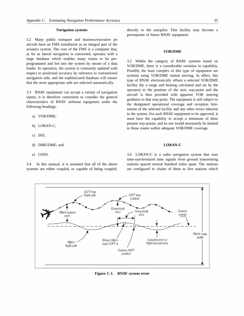
Appendix C. Estimating Navigation Performance Accuracy 35
a
ny.re
is
theeg
tomi-ent, iteeted
esg
ionsh
Navigation systems
3.2 Many public transport and business/executive jetaircraft have an FMS installation as an integral part of theavionics system. The core of the FMS is a computer that,as far as lateral navigation is concerned, operates with alarge database which enables many routes to be pre-programmed and fed into the system by means of a dataloader. In operation, the system is constantly updated withrespect to positional accuracy by reference to conventionalnavigation aids, and the sophisticated database will ensurethat the most appropriate aids are selected automatically.
3.3 RNAV equipment can accept a variety of navigationinputs; it is therefore convenient to consider the generalcharacteristics of RNAV airborne equipment under thefollowing headings:
a) VOR/DME;
b) LORAN-C;
c) INS;
d) DME/DME; and
e) GNSS.
3.4 In this manual, it is assumed that all of the abovesystems are either coupled, or capable of being coupled,
directly to the autopilot. This facility may become prerequisite of future RNAV equipment.
VOR/DME
3.5 Within the category of RNAV systems based oVOR/DME, there is a considerable variation in capabilitPossibly the least complex of this type of equipment asystems using VOR/DME station moving. In effect, thtype of RNAV electronically offsets a selected VOR/DMEfacility (by a range and bearing calculated and set by operator) to the position of the next way-point and thaircraft is then provided with apparent VOR steeringuidance to that way-point. The equipment is still subjectthe designated operational coverage and reception litations of the selected facility and any other errors inherin the system. For such RNAV equipment to be approvedmust have the capability to accept a minimum of thrpresent way-points, and its use would necessarily be limito those routes within adequate VOR/DME coverage.
LORAN-C
3.6 LORAN-C is a radio navigation system that ustime-synchronized time signals from ground transmittinstations spaced several hundred miles apart. The statare configured in chains of three to five stations whic
Figure C-1. RNAV system error

36 Manual on Required Navigation Performance (RNP)
canalngtualy ofuldus
ndix
atahisoneo,
ngeill
Es
forntle
tyee
cke
ntonstlye.ely,
ybe to
transmit with the same group repetition interval. Withineach chain, one station is designated as master and theremainder as secondaries; the master has unique pulse andphase transmission characteristics to distinguish it from thesecondaries.
3.7 Aircraft position is derived by measuring thedifference in arrival time of LORAN-C pulses from three ormore ground stations. LORAN-C equipment may be astand-alone system, but modern systems are more usuallyintegrated with a navigation computer in order to providepositional and associated information.
3.8 The LORAN-C ground wave is used for navigationand adequate signal coverage is normally in the region ofabout 1 700 km (900 NM). The usable coverage area may,however, be affected by ground conductivity, atmosphericor other interference with the signal reception.
3.9 There are a number of disadvantages to theLORAN-C system:
a) the signals are subject to local interference fromsuch sources as low frequency transmitters andpower line emissions;
b) a failure of one transmitter can leave a major areawithout coverage; and
c) approval of LORAN-C for RNAV operations willbe limited to the geographical area of good groundwave signal reception.
INS
3.10 The INS is totally self-contained equipment thatoperates by sensing aircraft accelerations with agyro-stabilized platform. Output functions of the systeminclude accurate present position information, navigationdata, steering commands and angular pitch, roll andheading information. Most aircraft fitted with INS have aduplicated or triplicated system. The normal operatingpractice is to input the systems with the aircraft’s knownposition to a high degree of accuracy prior to departurefrom the aircraft stand. By pre-setting a series of way-points, the system will navigate the aircraft along apredetermined track. Way-points are usually fed into thesystem prior to departure, but new way-points can beinserted at any time.
3.11 The major disadvantage of INS is that its accuracybecomes degraded with elapsed time since the last update,for which a linear decay of 2.8 to 3.7 km (1.5 to 2 NM) perhour must be allowed, although significantly better
accuracies are often achieved in practice. Whereas INS be expected to guide an aircraft to within the normtolerances of a VOR-defined route system for somethiin excess of 1 850 km (1 000 NM) following correcalignment before departure, it is apparent that a basic dINS without automatic updating would not be sufficientlaccurate for use in such airspace following several hoursflight, unless special measures were adopted which woenable the pilot to verify system accuracy by varioupdating or cross-checking methods.
3.12 A substantial number of aircraft have three INSs ait is usual for these to be operated in so-called triple-mmode which provides an average of the positional dprovided by the three independent systems. Normally tprocess provides a better position estimate, because if of the three systems differs significantly from the other twits data can be excluded from the averaging process.
3.13 Many INSs have sophisticated automatic updatifacilities employing dual DME and/or VOR inputs. Thmost complex of these employ auto-tune devices which wcheck and provide constant updates from multiple DMwithin range of the aircraft (see also 3.14).
DME/DME
3.14 The most accurate means currently available updating RNAV and flight management system equipmewithin continental airspace is by reference to multipDMEs, with a minimum of two suitably positionedfacilities being needed to provide a position fix. The qualiof the positional information will be dependent on threlative geometry of the DMEs and their range from thaircraft, and therefore the system will have a fall-baroutine whereby other combinations of aids may butilized.
GNSS
3.15 GNSS are evolving. GNSS providing independenavigation, where the user performs on-board positidetermination from information received from broadcatransmissions by a number of satellites, will provide highreliable, highly accurate and high integrity global coveragAlthough the RNP concept allows for more than onsatellite navigation system to be in use simultaneousfrom an aircraft equipment point of view, maximuminteroperability is essential as it would significantlsimplify avionics and thereby reduce cost. It would also beneficial if one system could serve as a complementand/or in a backup role for the other.

Appendix C. Estimating Navigation Performance Accuracy 37
onif
csis
ofe,red.thewill
oraytedVn
heluely to
tsnraft ortryre
laythee
heys
ntebe ise, tos to
thet.
3.16 Criteria to enable adequate integrity monitoring andhealth warning services for satellite navigation systemsmust be developed. Two distinct approaches to the problemof integrity, namely receiver autonomous integritymonitoring (RAIM) and the provision of a GNSS integritychannel (GIC) have been identified. Both are underinvestigation in several States and international organiz-ations. Subject to the satisfactory development of integritymonitoring, it is confidently expected that GNSS will meetthe civil aviation requirements for navigation.
4. NAVIGATION ERRORCHARACTERISTICS
Navigation system error
4.1 Navigation system error is defined at the output of thenavigation receiver and therefore includes both the signal-in-space and airborne equipment error. The unique signalcharacteristics of a navigation system can have many errorcomponents, including propagation error, errors in thetransmitted signal arising from geographical siting,magnetic alignment of the ground station and receiver errorssuch as receiver noise. The distribution and rate of change,as well as the magnitude of the errors, must be considered.Error distributions may contain both bias and randomcomponents. The bias component is generally easilycompensated for when its characteristics are constant andknown. For example, VOR radials can be flight-checked andthe bias error reduced or eliminated through correction ofthe radial used on aeronautical charts. The LORAN-Cseasonal and diurnal variations can also be compensated forby implementing correction algorithms in aircraft equipmentlogic and by publishing corrections periodically for use inair equipment. Ionospheric corrections may be incorporatedinto GNSS solutions.
4.2 The distribution of the random or nonpredictablevarying error component becomes the critical element to beconsidered in the design of navigation systems. The rate ofchange of the error within the distribution is also animportant factor, especially when the system is used forapproach and landing. Errors varying at a very highfrequency can be readily integrated or filtered out in theaircraft equipment. Errors occurring at a slower rate can,however, be troublesome and result in disconcertingindications to the pilot. An example of one of these typesof errors would be a “scalloped” VOR signal that causes thecourse display indicator (CDI) to vary. If the pilot attemptsto follow the CDI closely, the aircraft will start to “S-turn”frequently. The manoeuvring will cause unnecessary pilot
workload and degrade pilot confidence in the navigatisystem. This indication can be further aggravated navigation systems exhibit different error characteristiduring different phases of flight or when the aircraft manoeuvring.
4.3 In summary, the magnitude, nature and distributionerrors as a function of time, terrain, avionics, aircraft typaircraft manoeuvres and other factors must be consideThe evaluation of errors is a complex process, and comparison of systems based on a single error number be misleading.
RNAV computation error
4.4 Navigation system error/airborne equipment errcomponents, in accordance with common practice, minclude errors in the receiver outputs and errors contribuby the converter. In those cases in which an RNAequipment accepts inputs directly from the navigatioreceiver, the error components normally included for tconverter are not incurred; therefore, the appropriate vafor airborne equipment error can be correspondingreduced. The RNAV computation error can be estimatedbe the output resolution of the RNAV equipment.
Display system error
4.5 Display system error may include error componencontributed by any input, output or signal conversioequipment used by the display as it presents either aircposition or guidance commands (e.g. course deviationcommand heading) and by any course definition endevices employed. For systems in which charts aincorporated as integral parts of the display, the dispsystem error necessarily includes charting errors to extent that they actually result in errors in controlling thposition of the aircraft relative to a desired path over tground. To be consistent, in the case of symbolic displanot employing integral charts, any errors in way-poidefinition directly attributable to errors in the referencchart used in determining way-point positions should included as a component of this error. This type of errorvirtually impossible to handle and, in general practichighly accurate, published way-point locations are usedthe greatest extent possible in setting up such systemavoid such errors and to reduce workload.
Course selection error
4.6 Course selection error is the difference between desired course setting and the course that is actually se

38 Manual on Required Navigation Performance (RNP)
tbe
or,otot of
ty
drt
ssentE m
Etal
edknt
ysS-or
d
TEeas
h
atustoreed.
5. ERROR BUDGETS FOR FTE
General
5.1 FTE refers to the accuracy with which the aircraft iscontrolled, as measured by the indicated aircraft positionwith respect to the indicated command or desired position.It does not include procedural blunders which are grosserrors in human judgment, or inattentiveness that cause thepilot to stray significantly from the intended track.
5.2 It is difficult to completely characterize FTE.Equipment design and ambient environment variables affectFTE directly and measurably by affecting the processing ofthe basic display inputs. This includes determining thedisplay scale factors and other display configurationvariables which affect how guidance information isdisplayed. Compensating for aircraft control dynamics andair turbulence are examples of environmental variableswhich affect FTE. These factors must be taken into accountin arriving at empirical values for FTE contribution tosystem use accuracy.
5.3 Guidance signals can be coupled to the aircraft in oneof three modes: manual (raw CDI deviations), flightdirector or autopilot. Each of these modes has an errorbudget for FTE.
Manual FTE
5.4 The FTE, which is associated with manual modes,will vary widely depending on such factors as windconditions and the experience, workload, fatigue andmotivation of the pilot. The currently used 95 per centprobability for manual FTEs for the various phases of flightbased on 1978 United States Federal Aviation Adminis-tration (FAA) tests of VOR/DME are as follows:
Oceanic 3.7 km 2.0 NMEn-route 1.85 km 1.0 NMTerminal 1.85 km 1.0 NMApproach 0.93 km 0.5 NM
5.5 Experience has shown, however, that FTE is related tonavigation system and course sensitivity. Data collected todate from flight tests and flight simulations for microwavelanding system (MLS) RNAV straight-line segments undervarying wind conditions and aircraft types indicate a valueof 0.216 NM (400 m) may be appropriate for the approachphase at a 95 per cent probability. Curved approach pathdata indicate larger FTEs. The difference between the
VOR/DME values and MLS RNAV values indicates thathe current manual 95 per cent probability values may too conservative.
Coupled FTE
5.6 The RNAV system may be coupled to the AFCS the flight director. When RNAV is coupled to the AFCSthe tracking accuracy (FTE) is a function of the autopilgain and the AFCS guidance loop bandwidth. Autopilgain and bandwidth are in turn dependent on the phaseflight. When RNAV is coupled to the flight director, theadditional error source of flight director needle sensitivimust be considered.
5.7 There is very little published data on AFCS-coupleFTE. EUROCONTROL Experimental Centre RepoNo. 216, June 1988, entitled Navigational Accuracy ofAircraft Equipped with Advanced Navigation Systemdetermined that en-route AFCS-coupled system uaccuracy is approximately 1 200 m (0.66 NM) (95 per ceprobability). This would suggest that AFCS-coupled FTcould be as high as 400 m (0.22 NM) based on 1 000(0.5 NM) computation error for RNAV-DME-DME whichincludes inaccuracies due to the geometry of the DMstation, and a 50:50 weighted mix of analog and digiDME sensor accuracy (685 m (0.37 NM)(2-sigma)).
5.8 A second value of AFCS-coupled FTE may bobtained from manufacturers’ specifications. A limitereview of manufacturers’ specifications indicates tracaccuracy requirements of 463 m (0.25 NM) (95 per ceprobability) for equipment.
5.9 A value of AFCS-coupled FTE for approaches mabe obtained from MLS RNAV flight tests and simulationfor straight-line segments. These indicate that AFCcoupled FTE could be as low as 0.030 km (0.016 NM) fapproaches.
5.10 Limited data exist on flight director autocoupleFTE from flight tests and flight simulations for MLS RNAVstraight-line segments. These data indicate that an Fvalue of 0.061 km (0.033 NM) may be appropriate for thapproach phase at a 95 per cent probability. This value wdetermined under varying wind conditions and witdifferent aircraft types.
RNAV FTE
5.11 RNAV FTE cannot be completely characterized this time for all three aircraft modes, as extensive data mbe obtained with a variety of sensors and conditions befa complete statistical representation of FTE can be defin

Appendix C. Estimating Navigation Performance Accuracy 39
ea.htverceecttord
ly)..8Sr
andlues
Table C-1. Assumed FTE values (95 per cent probability)
Flight phaseManual
Coupled
Flight director Autopilotkm NM km NM km NM
Oceanic 3.7 2.0 0.93 0.50 0.463 0.25
En-route 1.85 1.0 0.93 0.50 0.463 0.25
Terminal 1.85 1.0 0.93 0.50 0.463 0.25
Approach 0.93 0.5 0.463 0.25 0.231 0.125
The purpose here is to use preliminary findings to establishan assumed system error budget based on various datasources, fully recognizing that the database is incomplete.This assumed FTE should satisfy the requirements ofsystem users and system planners.
5.12 Table C-1 presents assumed FTE values. ManualFTE figures in Table C-1 are those currently used in FAA,RTCA and ICAO documents.
5.13 AFCS-coupled FTE of 463 m (0.25 NM) for enroute appears to be substantiated by the EUROCONTROLdata and manufacturers’ specifications. Assuming that theapproach FTE will be at least twice as accurate as en-routeFTE, an approach FTE of 231 m (0.125 NM) is derived.This may be compared to the MLS RNAV value of 30 m(0.016 NM).
5.14 Flight director-coupled FTE is derived from thmanual and AFCS-coupled FTE and MLS RNAV datBased on the MLS RNAV tests, it is assumed that a fligdirector has at least a sixfold increase in FTE accuracy omanual flight, but has twice the error of an autopilot. Sinthe AFCS-coupled FTE values are reasonable with respto available data, the assumption is made that flight direcFTE will have at least twice the error of AFCS-coupleflight. This resultant flight director FTE of 463 m(0.25 NM) for the approach phase may be directcompared to the MLS RNAV value of 61 m (0.033 NMThe factor of 7.5 difference is comparable to the factor 7difference for assumed AFCS-coupled FTE and the MLRNAV value of 30 m (0.016 NM). This approximate ordeof magnitude difference between assumed FTE values measured FTE values indicates that the assumed vamay be conservative.

s
as
nt
e
a
Appendix D
REFERENCE DOCUMENTATION RELATEDTO AREA NAVIGATION
Australia
1. CAA Doc. ON 10, Operational Notes on AreaNavigation Systems
2. CAA Publication Number 50, Airborne Radio Equip-ment Classification
3. CAA Publication, Flying Operational Standards andInstructions
4. CAA Publication, CAAP B-RNAV-1, Approval ofAustralian Operators and Aircraft to Operate underInstrument Flight Rules in European AirspaceDesignated for Basic Area Navigation (RNP 5)
5. CAA Publication, CAAP RNP 10-1, RequiredNavigation Performance 10 Operational Approval
Canada
1. Guidance material on the application of AreaNavigation (RNAV) in Canadian domestic airspace— TP 9064E.
2. ATC RNAV Control Procedures — Manual ofOperations — TP-703
Europe
1. National Civil Aviation Legislation
2. Aeronautical Information Circulars
3. Airworthiness Notices
4. EUROCAE ED-39, Minimum Operational Perform-ance Requirements (MOPR) for Airborne RNAVSystems based on two DME as sensors
5. EUROCAE ED-40, Minimum Performance Specifi-cation (MPS) for Airborne RNAV ComputingEquipment based on two DME as sensors
6. EUROCAE ED-27, MOPR for Airborne Area Navi-gation System based on VOR and DME as sensor
7. EUROCAE ED-28, MPS for Airborne RNAVComputing Equipment based on VOR and DME sensors
8. EUROCAE ED-12A/RTCA DO-178A, SoftwareConsideration in Airborne Systems and EquipmeCertification
9. EUROCAE ED-14B/RTCA DO-160B, Environ-mental Conditions and Test Procedures for AirbornEquipment
10. EUROCAE ED-58 (Draft), MOPR for AirborneRNAV Equipment using Multi-sensor Inputs
11. EUROCAE ED-75, Minimum Aviation SystemPerformance Standards (MASPS) for RNP AreNavigation
12. CAP360, Guidance to UK AOC Holders
13. NAT Doc. 001, T13.5N/5, Guidance and InformationMaterial concerning Air Navigation in the NATRegion
14. EUR Doc. 001, RNAV/4, Strategy for the Implemen-tation of RNAV in the European Region (4th Edition)
15. SAE ARP 1570 (Proposed), Flight ManagementComputer System
16. EUROCONTROL Standard on Area Navigation,Operational and Functional Requirements
40

Appendix D. Reference Documentation Related to Area Navigation 41
l
,t
nd
nE
t
t
n
,)
na
17. Joint Airworthiness Authorities, AMJ 20-X2, JAAGuidance Material on Airworthiness Approval andOperational Criteria for the Use of NavigationSystems in European Airspace Designated for BasicRNAV Operations (RNP 5)
United States
1. AC 20-115A, Radio Technical Commission forAeronautics (RTCA) DO-178A (8/12/86)
2. AC 20-121A, Airworthiness Approval of AirborneLORAN-C Navigation Systems for Use in the U.S.National Airspace System (NAS) (8/24/88)
3. AC 20-129, Airworthiness Approval of VerticalNavigation (VNAV) Systems for Use in the U.S. NASand Alaska (9/12/88)
4. AC 25-4, Inertial Navigation Systems (INS) (2/18/66)
5. AC 90-45A, Approval of Area Navigation Systems foruse in the U.S. National Airspace System (2/21/75)
6. AC 90-76B, Flight Operations in Oceanic Airspace(1/29/90)
7. AC 90-79, Recommended Practices and Proceduresfor the Use of Electronic Long Range NavigationEquipment (7/14/80)
8. AC 90-82B, Direct Routes in the Conterminous U.S.(7/15/90)
9. AC 91-49, General Aviation Procedures for Flight inNorth Atlantic Minimum Navigation PerformanceSpecifications Airspace (8/23/77)
10. AC 120-33, Operational Approval of Airborne LongRange Navigation Systems for Flight Within theNorth Atlantic Minimum Navigation PerformanceSpecifications Airspace (6/24/77)
11. AC 121-13, Self-contained Navigation Systems (LongRange) (10/14/69)
12. Federal Aviation Administration Order 8400.10, AirTransportation Operations Inspector Handbook,Volume 4 — Aircraft Equipment and OperationaAuthorizations, Chapter 1 — Air Navigation
13. Federal Aviation Administration Handbook8260.3B, U.S. Standard for Terminal InstrumenProcedures (TERPS), Chapter 15 — Area Navigation(RNAV)
14. AC 20-130, Airworthiness Approval of Multi-sensorNavigation Systems for use within the U.S. NAS aAlaska (9/12/88)
15. RTCA/DO-180 A, Minimum Operational Perform-ance Standards for Airborne Area NavigatioEquipment Using a Single Collocated VOR/DMSensor Input (5/24/90)
16. RTCA/DO-187, Minimum Operational PerformanceStandards for Airborne Area Navigation EquipmenUsing Multi-sensor Inputs (11/13/84)
17. RTCA/DO-194, Minimum Operational PerformanceStandards for Airborne Area Navigation EquipmenUsing LORAN-C Inputs (11/17/86)
18. RTCA/DO-236, Minimum Aviation System Perform-ance Standards (MASPS) for RNP Area Navigatio
19. ARINC Characteristics 702-1, Flight ManagementComputer System
20. TSO C115, Airborne Navigation Equipment usingMulti-sensor Inputs
21. Federal Aviation Administration Order 8400.12ARequired Navigation Performance 10 (RNP 10Operational Approval
22. AC 90-96, Approval of U.S. Operators and Aircraftto Operate under Instrument Flight Rules (IFR) iEuropean Airspace Designated for Basic AreNavigation (BRNAV/RNP 5)
— END —