DNVGL-ST-0412 Design and construction of large modern ...€¦ · Appendix A Documents to be...
37
The electronic pdf version of this document, available free of charge from http://www.dnvgl.com, is the officially binding version. DNV GL AS STANDARD DNVGL-ST-0412 Edition December 2016 Design and construction of large modern yacht rigs
Transcript of DNVGL-ST-0412 Design and construction of large modern ...€¦ · Appendix A Documents to be...

The electronic pdf version of this document, available free of chargefrom http://www.dnvgl.com, is the officially binding version.
DNV GL AS
STANDARD
DNVGL-ST-0412 Edition December 2016
Design and construction of large modernyacht rigs

FOREWORD
DNV GL standards contain requirements, principles and acceptance criteria for objects, personnel,organisations and/or operations.
© DNV GL AS December 2016
Any comments may be sent by e-mail to [email protected]
This service document has been prepared based on available knowledge, technology and/or information at the time of issuance of thisdocument. The use of this document by others than DNV GL is at the user's sole risk. DNV GL does not accept any liability or responsibilityfor loss or damages resulting from any use of this document.

Cha
nges
- c
urre
nt
Standard — DNVGL-ST-0412. Edition December 2016 Page 3Design and construction of large modern yacht rigs
DNV GL AS
CHANGES – CURRENT
This is a new document.

Con
tent
s
Standard — DNVGL-ST-0412. Edition December 2016 Page 4Design and construction of large modern yacht rigs
DNV GL AS
CONTENTS
Changes – current.................................................................................................. 3
Section 1 Design and construction of large modern yacht rigs............................... 51.1 General............................................................................................. 51.2 Certification and verification systematics......................................... 51.3 Design and construction principles...................................................71.4 Materials and fabrication................................................................ 271.5 Miscellaneous..................................................................................311.6 Certificate....................................................................................... 33
Appendix A Documents to be submitted for rig analysis.......................................34A.1 Global rig basic analysis, global rig motoring analysis, global rignatural frequencies analysis.................................................................34A.2 Global mast tube stress/strain analysis......................................... 34A.3 Global boom analysis......................................................................34A.4 Local mast tube analysis................................................................ 34
Changes – historic................................................................................................36

Standard — DNVGL-ST-0412. Edition December 2016 Page 5Design and construction of large modern yacht rigs
DNV GL AS
SECTION 1 DESIGN AND CONSTRUCTION OF LARGE MODERN YACHTRIGS
1.1 General
1.1.1 Scope
1.1.1.1 This standard applies to sailing yachts of L > 24 m.
1.1.1.2 Scope of this standard is the structural integrity of one- or multiple-masted, Bermudian riggedmonohull or multihull sailing yachts with spars made of carbon fibre reinforced plastics (CRP) or aluminiumalloy; including the dimensioning of standing rigging, mast and boom sections as well as local construction inway of fittings structurally attached to the spars.
1.1.1.3 For other rigged sailing yachts, the principles presented in the following shall be used as a generalguidance. Any detailed analysis which is leading to different reserve or reduction factors can be submitted onthe basis of an equivalent safety.
1.1.1.4 Upon request, the performance on construction can be supervised by DNV GL. Basis for this is arelevant shop approval for the typical construction techniques. The survey will be carried out in periodicalintervals where an assessment is made whether the product under supervision is built in accordance withapproved documentation and the societies standards by random control.
1.2 Certification and verification systematics
1.2.1 General
1.2.1.1 The relation between the customer and DNV GL is regulated in an agreement signed by both parties.The agreement specifies the scope of the service, the fee, terms of payment and legal obligations.
1.2.1.2 The certification service is performed on the basic assumption that all parties involved (designer,builder/yard, manufacturer, design-owner, sub-contractor, owner, etc.) fulfil their individual obligations.The certification service is not performed in substitution of other parties' role or obligations. Nothingcontained in DNV GL services, certificate, report or document issued in connection with or pursuant to theserequirements, shall relieve any designer, engineer, builder, manufacturer, yard, seller, owner, operator orother parties from any obligations or consequences of default whatsoever. In particular, compliance with therequirements does not imply acceptance or commissioning of a craft. This is the exclusive responsibility ofthe owner.
1.2.2 Procedure1.2.2.1 General
1.2.2.1.1 The certification/verification procedures are based on modules. These procedures (modules) coverthe design phase, the manufacturing phase or both. The procedures are based on the modules specified inthe agreement.
1.2.2.1.2 Application for certification/verification shall be sent to the undersigned DNV GL office and include:
— name and address of the applicant— name and address of the builder (yard, manufacturer) craft specification and type designation

Standard — DNVGL-ST-0412. Edition December 2016 Page 6Design and construction of large modern yacht rigs
DNV GL AS
— chosen procedure(s)/module(s)— technical documentation.
1.2.2.1.3 The applicant has to be authorised by the owner of the design to act on his behalf.
1.2.2.1.4 If the applicant subcontract design or production, the applicant remains responsible for theexecution of conformity assessment for all technical documentation, sub-supplies and the finished rig.
1.2.2.1.5 Any subcontracting will be subject to separate agreement, handling and approval.
1.2.2.1.6 DNV GL decides the extent of examinations, tests and inspections required to complete the relevantprocedure (module) in each case.
1.2.3 Technical documentation1.2.3.1 General requirements
1.2.3.1.1 All documents submitted to DNV GL shall be in English language.
1.2.3.1.2 The drawings shall contain all data necessary for assessment and approval. Where deemednecessary, calculations and descriptions of the yacht's elements shall be submitted. Any non-standardsymbols used shall be explained in a key list. All documents shall show the project name, drawing numberand revision number.
1.2.3.1.3 Submitted documentation about performed calculations shall contain all necessary informationconcerning reference documents, literature and other sources. The calculations shall be compiled in a waywhich allows identifying and checking all steps. Handwritten, easily readable documents are acceptable.Where appropriate, results of calculations shall be presented in graphic form. A written conclusion shall beprovided.
1.2.3.1.4 DNV GL reserves the right to inquire additional documentation if the submitted is insufficient for anassessment of the rig or essential parts thereof. This may especially be the case for components related tonew developments and/or which have not been tested on board to a sufficient extent.
1.2.3.2 Guidance for submission of documents
1.2.3.2.1 Upon request the list of required documents to be submitted will be provided by DNV GL
1.2.3.2.2 Drawings shall be submitted in pdf format in general. The documents to be submitted forplan approval are listed below. For the purpose of submission, DNV GL provides a digital platform calledMYDNVGL.
1.2.3.2.3 General information
— list of submitted drawings (title, drwg.no., date of latest revision)— general arrangement, deck plan, sail plan— technical specification (main dimensions, displacement, etc.)— DNV GL rig input sheet.
1.2.3.2.4 Relate to App.A for the scope of documents and information required for certification listed for eachof the different certification modules.

Standard — DNVGL-ST-0412. Edition December 2016 Page 7Design and construction of large modern yacht rigs
DNV GL AS
1.2.4 Certificate/statement of compliance1.2.4.1 General
1.2.4.1.1 The issuing of a certificate or statment of compliance is based on the chosen modules/ packagespecified in the agreement.
1.2.4.1.2 The type of certificate to be issued by DNV GL for compliance will be:
— product certificate.
1.2.4.1.3 The certificate/statement of compliance shall contain the following information as applicable:
— the name and address of the builder (yard, manufacturer)— the identification of the product- craft type designation and reference to owner of the design— reference to the standard and regulations applied— scope of work— specification of exemptions or equivalent standards— date of issue and signatures.
1.3 Design and construction principles
1.3.1 General
1.3.1.1 Generally, the basic value for all following evaluations is the static righting moment (RM) of the yachtat full displacement with a heel angle corresponding to the safe working angle (SWA).
1.3.1.2 The safe working angle (SWA), which will be referred to in the following, generally representsa heeling angle of 25°. However, other angles may be defined as SWA in agreement with DNV GL. DNVGL reserves the right to assess the SWA according to the relevant characteristics of the yacht under sailaccording to Table 1-1 or special characteristics such as canting keel.
1.3.1.3 Large cruising catamarans require a different approach defining a basic design parameter. Where therighting moment is a very common value for monohulls, this is not so for "heavy" cruising catamarans. Thesevessels often provide excessive stability which makes it impractical to work from. Rather a more direct, yetconservative, approach is taken by using the wind pressure directly.
1.3.2 Load cases1.3.2.1 Ordinary sailing conditionsUpwind beating, reaching and broad reaching under appropriate sail configurations for light, moderate,strong and stormy wind conditions, such as:
— full main, working jib, genoa I or reacher— several reef stages main, working jib, reefed jib, stay sail— spinnaker only— others and special configurations for special rigs.

Standard — DNVGL-ST-0412. Edition December 2016 Page 8Design and construction of large modern yacht rigs
DNV GL AS
Table 1-1 Yacht characteristics
Category Displacement characteristics Typical purposecharacteristics
Typical handlingcharacteristics
I Motor sailer/heavy cruiser Ocean going Handled by owner/crew
II Mid displacement Offshore Short-handed
III Light displacement Coastal pleasurecruises/club racing
Short-handed orhandled by crew
IV Ultra light displacement Racing Handled by professional crew
1.3.2.2 Extreme conditionsExtreme conditions may need to be defined in special cases, depending on the boat size and type and otherconfigurations.
1.3.3 Determination of rig loads1.3.3.1 Pretensioning of rigThe pretensioning of the rigging shall be specified by the designer, otherwise pretensioning is set to avoidslack leeward cap shrouds with an appropriate reserve, when sailing at heeling angles at or below the SWA.
1.3.3.2 Transverse sail forces
1.3.3.2.1 MonohullsTransverse forces are determined from righting moment:
Each sail's contribution to the resultant heeling moment is assumed to be proportional to the sail’s area andthe distance of its centre of effort above the underwater body's centre of lateral resistance, see Figure 1-1.The sum of these heeling moments is set equal to the vessel’s righting moment under the conditions andspecific sail configurations being evaluated:
Transverse force from mainsail:
[N]
Transverse force from foresail:
[N]
Transverse force from spinnaker when broaching:
[N]

Standard — DNVGL-ST-0412. Edition December 2016 Page 9Design and construction of large modern yacht rigs
DNV GL AS
Figure 1-1 Centres of effort
RMDesign = righting moment as defined in [1.3.1] [Nm]CoEm/f/s = centre of effort of respective sail:
CoEm = 0.39 P above gooseneck [m] (default)CoEf = 0.39 I above foot [m] (default)CoEs = 0.59 I above deck [m] (default)
CLR = the centre of lateral resistance of the underwater body (including appendages) [m]Am = mainsail area, projected laterally [m2]Af = foresail area, projected laterally [m2]P = mainsail hoist [m]E = foot of mainsail [m]I = height of fore triangle [m]SFCm = side force coefficient mainsail
= 0.9SFCf = side force coefficient foresail
= 1.1
1.2.3.2.1.1 Estimation of corresponding apparent wind speed for upwind cases
[m/s]
where:
ρ = density of air [kg/m3].
1.3.3.2.2 Multiple-mast rigFor a multiple-mast rig a conservative assumption of the proportioning of righting moment shall be made:
For all relevant sail configurations, the fractions of sail area moments (SAM) for each mast from the totalSAM shall be determined to find the design righting moment for each mast.

Standard — DNVGL-ST-0412. Edition December 2016 Page 10Design and construction of large modern yacht rigs
DNV GL AS
The sail area moment is defined as:
[m3]
where:
A = projected sail area.
The sail area moment for each mast is defined as:
[m3]
where:
i = index for specific mastj = index for specific sail on specific mast.
The fraction of each mast from the total sail area moment is defined as:
The design righting moment RMdesign for each mast shall be taken the lower of:
— RMdesign = 1.0 · (RM at SWA)— RMdesign = 1.56 · f · (RM at SWA).
Windage of masts and rigging (and equipment) and therewith contribution to (each) SAM and/or (OTM) maybe taken into account.
OTM = overturning moment, see [1.3.3.2.3].
1.3.3.2.3 MultihullsThe relevant apparent wind speed, resulting from the true wind speed and the predicted boat speed is usedto calculate the pressure forces for a rig.
where:
TWS = true wind speedTWA = true wind angleBS = boat speed.
This operational wind speed AWS0 is defining the safe operational limits for the vessel, equivalent to a safeworking heel angle on monohulls, which may not be exceeded. The operational limits of a rig need to bedefined precisely and followed diligently.

Standard — DNVGL-ST-0412. Edition December 2016 Page 11Design and construction of large modern yacht rigs
DNV GL AS
The design wind speed, which a rig is designed to, needs to be determined conservatively. As a catamarandoes not "heel away" from wind forces, a gust factor is introduced as a buffer, which acts as a multiplier onTWS (true wind speed).
The design wind speed is calculated using the above equation with the true wind speed multiplied by factor of1.25:
From this wind speed the sail pressure forces are calculated using the equation:
where:
ρ = density of air.
The side force coefficient cs for a mainsail is generally 0.9, for a jib 1.1. These pressure forces are supposedto act at the sails centre of effort, where the assumptions for the locations are:
Mainsail 45% of mean height for sails with normal roach.
Headsail 39% of mean height of triangular sail.
Looking at a different angle of this approach, these sail pressure forces calculated from the design windspeed result in an overturning moment (OTM). If really required for reference, the OTM shall be calculatedabout the vessel's longitudinal axis, at an elevation which can be called "platform" of the rig, mostly deck orsheerline level.
What has been found from studies is that obviously the AWS is a conservative value to work with. Whilebearing away from upwind the allowable TWS gets higher and also the AWS gets slightly higher. But theOTMs stay rather constant or even get marginally smaller. So actually, for all "upwind sail" configurations, anAWS limit is conservative and serves well for dimensioning purposes. Downwind cases need to be looked atseparately, at a certain OTM (guideline: similar to upwind) and a windpressure due to an AWS of 25 kn.
1.3.3.2.4 Distribution of transverse sail forces of the mainsailA set of point loads shall be calculated from Ftm acting on the mast as shown in Figure 1-2. The point loaddistribution shall be appropriate for the specified sail configuration and shall reproduce the equilibrium ofmoments. Table 1-2 shows examples of such point load distributions.
Table 1-2 Possible approaches for mainsail load distribution, unreefed
Distribution factor cim
3-spreader-rig 4-spreader-rig 5-spreader-rig
Clew 1) (0.25) (0.25) (0.25)
Gooseneck, tack 0.0 0.0 0.0
Spreader 1 0.05 0.0 0.0
Spreader 2 0.15 0.05 0.0
Spreader 3 0.25 0.15 0.05
Spreader 4 — 0.25 0.15

Standard — DNVGL-ST-0412. Edition December 2016 Page 12Design and construction of large modern yacht rigs
DNV GL AS
Spreader 5 — — 0.25
Main headboard 0.30 0.30 0.30
1) Not applied on rig explicitly.
Figure 1-2 Mainsail load distribution
Fim = [N], where
Ftm = transverse force mainsail according to [1.3.3.2]
cim = distribution factor with:
zi = according to Figure 1-2.

Standard — DNVGL-ST-0412. Edition December 2016 Page 13Design and construction of large modern yacht rigs
DNV GL AS
1.3.3.2.5 Distribution of transverse sail forces of the foresail
Figure 1-3 Foresail point loads
Fif = [N], where
Ftf = transverse force foresail according to [1.3.3.2]
cif = distribution factor with:
zi = according to Figure 1-3.
Table 1-3 shows an example of the foresail load distribution.
Table 1-3 Approach for foresail load distribution
cif
Tack 1) (0.3)
Clew 1) (0.3)
Head 0.4
1) Not applied on rig explicitly.
Standard — DNVGL-ST-0412. Edition December 2016 Page 14Design and construction of large modern yacht rigs
DNV GL AS
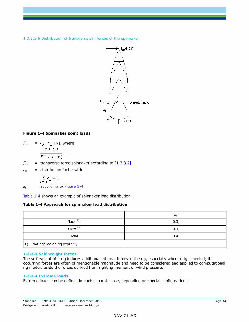
1.3.3.2.6 Distribution of transverse sail forces of the spinnaker
Figure 1-4 Spinnaker point loads
Fis = [N], where
Fts = transverse force spinnaker according to [1.3.3.2]
cis = distribution factor with:
zi = according to Figure 1-4.
Table 1-4 shows an example of spinnaker load distribution.
Table 1-4 Approach for spinnaker load distribution
cis
Tack 1) (0.3)
Clew 1) (0.3)
Head 0.4
1) Not applied on rig explicitly.
1.3.3.3 Self-weight forcesThe self-weight of a rig induces additional internal forces in the rig, especially when a rig is heeled; theoccurring forces are often of mentionable magnitude and need to be considered and applied to computationalrig models aside the forces derived from righting moment or wind pressure.
1.3.3.4 Extreme loadsExtreme loads can be defined in each separate case, depending on special configurations.

Standard — DNVGL-ST-0412. Edition December 2016 Page 15Design and construction of large modern yacht rigs
DNV GL AS
1.3.4 Determination of working loads of running and standing rigging1.3.4.1 Running riggingThe following approaches shall be seen as a general estimation of an initial calculation value. Care shall betaken, when configurations require modified approaches.
1.3.4.1.1 HalyardsThe working load of a halyard is generally generated by membrane forces in a sail. Its magnitude depends onthe amount of sag of the leech including a preload due to hoisting. Determination of the halyard load shall bebased on design righting moment and the following sail configuration:
Full main and 100% foresail (i.e. the foresail foot length equals J).
J = base of fore triangle [m].
1.3.4.1.1.1 Mainsail and/or mizzensail halyards:
[N]
where:
Fml = mainsail leech load
= [N]
fr = roach factor
=
Ftm = according to [1.3.3.2]s = sag fraction
= 0.065 [–], (6.5% of leech length) for all categories.
1.3.4.1.1.2 Foresails (genoa, jib, staysail, etc.) halyards
[N]
where:
Ftf = according to [1.3.3.2]s = sag fraction
= 0.045 [–], (4.5% of leech length).
1.3.4.1.2 Boom outhaulThe force of the outhaul is generated by the horizontal component of the leech load and a force resultantfrom the sag of the sail foot.
[N]
where:
Fml = according to [1.3.4.1.1.1]

Standard — DNVGL-ST-0412. Edition December 2016 Page 16Design and construction of large modern yacht rigs
DNV GL AS
Ftm = transverse force from mainsail according to [1.3.3.2].
For P and E see [1.3.3.2.1].
1.3.4.1.3 MainsheetThe working load of the mainsheet is estimated by a given sag of the leech. Its vertical component Fmsv iscalculated by the equation:
[N]
where:
Xms = sheet attachment point on boom aft of gooseneck [m]Fml = according to [1.3.4.1.1.1].
1.3.4.1.4 VangThe maximum vang loads normally occur when reaching or running downwind. Base value for calculatingthe vang load is again the leech load of the mainsail which in turn is determined by the sag fraction specifiedbelow. By omitting the mainsheet load contribution the following equation for the vang load Fv results fromforce equilibrium according to Figure 1-5.
Figure 1-5 Vang load determination
[N]
where:
Fml = according to [1.3.4.1.1.1]xv = distance from gooseneck to boom vang fitting [m]α = angle between vang and booms = sag fraction (proposals)
= 0.25 [–], (25% of leech length) for category I, II= 0.20 [–], (20% of leech length) for category III= 0.15 [–], (15% of leech length) for category IV.

Standard — DNVGL-ST-0412. Edition December 2016 Page 17Design and construction of large modern yacht rigs
DNV GL AS
1.3.4.1.5 Spinnaker poleNormally, the maximum working compression of the spinnaker pole occurs under tight reaching condition,when the spinnaker pole points straight forward. The load induced is assumed to be generated by aninteraction between afterguy and pole according to Figure 1-6.
Figure 1-6 Spinnaker pole force
Maximum working compression of spinnaker pole:
[N]
where:
Fi (tack) = relevant Fis according to [1.3.3.2.6]
α =
b = distance of deflection sheave from centre line or length of jockey pole [m].
It shall be considered whether a supplement shall be made due to sheet loads (for rather flat spinnakers orgennakers).
1.3.4.2 Standing riggingDNV GL examines standing rigging sizes by calculating tensile forces and correlate them with the reservefactors according to [1.3.5.1]. Calculation method is geometric non-linear finite element analysis. The tensileforces determined this way are also called maximum working loads (MWL) under the conditions of thisstandard.
Note:Working loads of longitudinal stays can be determined analytically (see [1.3.4.2.2]).
---e-n-d---o-f---n-o-t-e---
1.3.4.2.1 ShroudsCalculation of shroud working loads shall be based on the input specified in [1.3.1.2.3].
1.3.4.2.2 HeadstaysThe working load is the resultant axial force due to sag of a sail-carrying headstay.
The sag is the maximum transverse deflection of a line under a lateral uniform load between its end points.

Standard — DNVGL-ST-0412. Edition December 2016 Page 18Design and construction of large modern yacht rigs
DNV GL AS
The values specified below are relevant for the load case of a full main combined with a jib of 100% forestay-triangle area or reefed main combined with staysail at SWA. The lateral load q is a uniform load equivalent tothe force Ftf defined in [1.3.3.2.1], see Figure 1-7.
Headstay working load Fhs:
[N]
where:
q = [N/m]
l0 = stay length [m]s = the magnitude of sag s as a fraction of the stay length shall not be taken more than according to
Table 1-5.
Figure 1-7 Headstay load
Table 1-5 Headstay sag
Sag
Cat. IV Cat. III Cat. II Cat. I
Primary headstay 0.7% 1.0% 1.5% 2.0%
Secondaryheadstay(s) 1.5% 2.5% 3.0% 5.0%

Standard — DNVGL-ST-0412. Edition December 2016 Page 19Design and construction of large modern yacht rigs
DNV GL AS
Deviations from these indexes can only be considered in well-founded cases, resulting from exceptional sailand/or design characteristics.
Working loads for non-sail-carrying headstays (inner forestays, baby stays) are not explicitly specified here.In this case, design criterion is the rig’s required longitudinal stiffness dealt with in [1.3.5.2].
1.3.4.2.3 Backstay(s)For masthead rigs, backstay design load is obtained by opposing the forestay design load under equilibriumof moments about the mast base. In case of swept spreaders a contribution of cap shrouds may beconsidered.
1.3.4.2.4 Runners, check stays, etc.Runner and/or check stay design loads are obtained by opposing the forward longitudinal stays design loadsunder equilibrium of moments about the mast base.Besides, runners may be necessary not only to control but also to support and stabilise the rig, see [1.3.5.2].
1.3.5 Global analysis1.3.5.1 Standing rigging
1.3.5.1.1 GeneralDiagonal shrouds shall generally have a minimum angle to the mast centreline of 9°. If spreaders are swept,they shall be swept evenly, so that all shrouds are in plane on either side, when rig is unstressed. Spreadersweep angles between 5° and 9° are not advisable.While dimensioning of standing rigging, global rig stiffness characteristics shall be considered, since in caseof swept spreaders the "system stiffness" of the rig is also influenced by the dimensions and geometricarrangement of transverse rigging.
1.3.5.1.2 Dimensioning of standing rigging made of steel rodThe following reserve factors (RF) are valid provided working loads in standing rigging have been calculatedby static, geometric non-linear analysis. They are related to the ultimate break load specified by themanufacturer. If not explicitly mentioned, the following reserve factors are valid for Nitronic 50 Rod rigging. 1.3.5.1.2.1 Transverse rigging and jumperRF ≥ 2.5 on working loads determined according to [1.3.4.2]. 1.3.5.1.2.2 Fore and aft rigging, othersRF ≥ 2.0 on design load according to [1.3.4.2]RF ≥ 2.5 on design load according to [1.3.4.2] generally for category I yachts.
1.3.5.1.3 Dimensioning of standing rigging made of polymer fibre cablesFor fibre rigging elements, such as PBO or carbon strand cables, the working load determined by static,geometric non-linear analysis using the approaches offered in this standard so far may not exceed the cable'smaximum working load specified by the cable supplier. This maximum cable working load may be a DNV GL-certified value and thus/or be determined by the approach offered in DNVGL-CP-0413 class program for thetype approval of carbon strand and PBO cable rigging for sailing yachts. In lack of such proof, the followingreserve factors shall be used: 1.3.5.1.3.1 Transverse rigging and jumperRF ≥ 4.5 on working loads determined according to [1.3.4.2] including the self-weight effect.

Standard — DNVGL-ST-0412. Edition December 2016 Page 20Design and construction of large modern yacht rigs
DNV GL AS
1.3.5.1.3.2 Fore and aft rigging, othersRF ≥ 3.6 on design load according to [1.3.4.2] and soft aramid riggingRF ≥ 4.5 on design load according to [1.3.4.2] for category I yachts.
1.3.5.2 Stability analysisThe following stability evaluations are based on the determination of buckling modes. The reserve factorsversus buckling do not necessarily represent a safety against the occurrence of this failure mode, becausethe applied method assumes ideal straightness of the mast and its alignment with the forces which is not thecase in the realistic situation. Yet, the method provides a measure for assessing the rig's stiffness.
1.3.5.2.1 Global stability and stiffnessGlobal buckling is called the longitudinal buckling of the whole rig-system fore and aft. The following reservefactors are applicable for an evaluation according to the Euler eigenmode method. The determination of mastcompression levels is based on static, non-linear analysis.RF ≥ 3.1 on each set of mast panel compressions (resulting from all relevant working loads according to[1.3.4]).Global stiffness shall also be considered in case the yacht is driven with no mainsail, e.g. under engine,against heavy seaways.
1.3.5.2.2 Local stability and stiffnessLocal transverse buckling of the mast normally occurs as panel-buckling between transverse supports.Reserve factors are again applicable for an evaluation according to the Euler eigenmode method.RF ≥ 2.6 on each set of mast panel compressions resulting from all relevant working loads according to[1.3.4].
1.3.5.2.3 Shear stiffness of CRP-mast tubes25% (by weight) of the mast's basic laminate lay-up shall have ±45° fibre orientation to achieve a minimumshear and torsional stiffness. A stiffness correction of this content shall be taken into account in case ofdissimilar moduli of fibres running in 0° and 45°.See also [1.4.1.3] for minimum elastic properties of tubes.However special considerations are required for furling masts with open sections.
1.3.5.2.4 Thin wall buckling of the tubeTube wall buckling shall be considered.RF ≥ 3.0 on ultimate buckling stress or strain according to max. working compression in each wall panelresulting from load cases acc. to [1.3.2.1] (reserve factors are applicable for Roark and Young’s theoryof skin buckling under compression loads for curved, non-isotropic plates). Load concentrations shall beconsidered particularly in way of:
— mast step, especially when the mast can not be pitched— D-tangs— slots or halyard exits.
1.3.5.3 Spreader constructionSpreaders are subjected to axial, bending and shear loads. Each of the following scenarios described in[1.3.5.3.1] to [1.3.5.3.4] shall be considered. Proof of sufficient safety is based on "first principles" ofengineering. In Figure 1-8 and Figure 1-9 relevant arrangements and coordinates are shown. Relevantallowable strains and stresses are defined in [1.3.9.1.2], [1.3.9.1.3] and [1.3.9.1.4]. The design loads shallbe determined as follows:

Standard — DNVGL-ST-0412. Edition December 2016 Page 21Design and construction of large modern yacht rigs
DNV GL AS
1.3.5.3.1 Loading on windward side
Figure 1-8 Forces on a spreader
Figure 1-9 Spreader end detail
Fx = load in x-direction, resulting from relevant components of 2.5 times the calculated shroud workingloads [N]
Mby = bending moment resulting from 2.5 times the calculated working loads of Vn+1 with an offset of h(tip cup offset) [Nm]:
— for Navtec 528 Standard:Tip cup offset = 0.6 · diam. Vn+1
— for Navtec 534/834: 0.5 · diam Vn+1
— for others: to be specified
Tip cup moments else from this approach may be considered if a variation of load cases has beencalculated and the most conservative value resulting from combination of Vn, Vn+1 und Dn+1. Thismoment shall be multiplied by 2.5 for subsequent spreader calculations.

Standard — DNVGL-ST-0412. Edition December 2016 Page 22Design and construction of large modern yacht rigs
DNV GL AS
Fya = load in y-direction at spreader tip generated by mast bent (Fya max on windward side):
= [N]V1 = nominal break load or 2.5 times the calculated working load from V1 [N]k1 = 0.7 for non-swept spreaders
= 1.0 for 20° spreader-rake, interpolate in-betweenk2 = distribution factor according to Table 1-6Fyb = sectional loads in y-direction Fy at spreader tips obtained from finite element analysis (FEA)
= 2.5 · Fy [N]
The sectional loads in the spreaders are combinations from design loads listed above.
Table 1-6 Distribution factors
k2 3-spreader-rig 4-spreader-rig 5-spreader-rig
Spreader 1 0.7 0.6 0.6
Spreader 2 1.0 0.9 0.8
Spreader 3 0.95 1.0 1.0
Spreader 4 — 0.96 0.95
Spreader 5 — — 0.85
1.3.5.3.2 Loading on leeward sideFyc = loads from mainsail pushing against each leeward spreader
[N]
where:
lp = [m]
n = number of spreadersP = mainsail hoist, see [1.3.3.2.1]ρ = density of air [kg/m3]vaws = design AWS according operational manual plus gust factor of 25%c1 = sail girth factor, see Table 1-7c2 = distribution factor, see Table 1-8c3 = overload factor
= 2.0E = foot of mainsail, see [1.3.3.2.1].
Choosing this method, all other design loads (Fx, Fya and Mby) are assumed to be zero.

Standard — DNVGL-ST-0412. Edition December 2016 Page 23Design and construction of large modern yacht rigs
DNV GL AS
Table 1-7 Girth factors
c1 3-spreader-rig 4-spreader-rig 5-spreader-rig
Spreader 1 0.75 0.8 0.83
Spreader 2 0.5 0.6 0.67
Spreader 3 0.25 0.4 0.5
Spreader 4 — 0.2 0.33
Spreader 5 — — 0.17
Table 1-8 Distribution factors
c2 3-spreader-rig 4-spreader-rig 5-spreader-rig
Spreader 1 0.5 0.5 0.4
Spreader 2 0.8 0.7 0.6
Spreader 3 1.0 0.9 0.8
Spreader 4 — 1.0 0.9
Spreader 5 — — 1.0
1.3.5.3.3 Spreader bucklingRF ≥ 1.1 for Euler-Buckling of spreader versus relevant design loads specified in [1.3.5.3.1].
1.3.5.3.4 Spreader wall bucklingRF ≥ 1.1 for thin wall buckling of spreader versus relevant design loads specified in [1.3.5.3.1].
1.3.6 BoomsBooms are subjected to compression, bending, shear and torsion primarily through the loads from sheet,leech, outhaul and vang, see Figure 1-10.
Figure 1-10 Forces on boom

Standard — DNVGL-ST-0412. Edition December 2016 Page 24Design and construction of large modern yacht rigs
DNV GL AS
Design loads:
1.5 × release load for max. possible relief valve setting [N]
1.0 × max. working loads of all relevant sheets, lines, outhauls, etc. [N]
1.0 × Mt (resulting torsional moment), see Figure 1-12.
[Nm]
where:
Fsh = horizontal component of mainsheet load [N], see Figure 1-11Fsail = component of mainsail load acting at mainsail clew [N], see Figure 1-11.
[N]
Figure 1-11 Mainsail clew
Figure 1-12 Boom section
v = apparent wind speed for design purpose = 19 m/s (35 kn)A = mainsail area [m2]ρ = density of air [kg/m3].
An appropriate combination of the above loads shall be assumed for the strength calculation.
It is strongly recommended to provide the vang with an overload relief valve. Otherwise the design load forthe boom in respect of forces due to the vang shall be replaced by:
1.0 × breaking load of vang [N]

Standard — DNVGL-ST-0412. Edition December 2016 Page 25Design and construction of large modern yacht rigs
DNV GL AS
The requirements for allowable strains and stresses as defined in [1.3.9.1.2], [1.3.9.1.3] and [1.3.9.1.4]shall be met when applying the design loads. Also wall buckling of the boom shall be considered.
1.3.7 Mast stepA mast step is subjected to compression and shear forces. Especially for keel-stepped masts, shear is mainlygenerated by boom compression.
1.3.8 Mast-panel between maststep and upper-most spinnaker poleposition (Panel 0)If the loading of Panel 0 due to vang, spinnaker/jockey pole and boom has not been part of the globalanalysis, these loads shall be taken into account additionally when designing Panel 0. The resultant loads dueto the following design loads shall be considered then:
Vang: resultant loads due to 1.5 × max. vang working-load according to [1.3.4.1.4] (for hydraulicdevice: vang load = release load at max. eased mainsheet)
Poles: 2 × resultant loads due to pole compression according to [1.3.4.1.5]
Gooseneck: resultant loads due to 1.5 × max. vang load (for hydraulic device: vang load = release load atmax. eased mainsheet plus other relevant contributions (outhaul, mainsheet etc.)).
1.3.9 Local analysis1.3.9.1 Local analysis of components made of multi-axial-carbon fibre laminate or aluminium alloyThe reduction factors and allowable material strains and stresses in this standard are applicable for thefollowing general engineering approaches (according to the classic laminate theory (CLT) for carbon fibrereinforced plastic). For 3-D finite element analysis the reduction factors shall be defined separately.
Pin seating:
— bearing stress/strain [MPa]:
εb =
— shear-out stress 1 (for CRP) [MPa]:
εst =
— tensile (hoop) stress [MPa]:
εhs =
where:
F = design load according to [1.3.9.1.1] [N]t = plate thickness [mm]d = pin hole diameter/bushing diameter [mm]e = distance from pin centre to edge of component in direction of load [mm]
1 Shear-out stress shall be considered for bolt-fastenings with an edge distance lower than 2d. In anycase, when plate material is not quasi-isotropic.
Standard — DNVGL-ST-0412. Edition December 2016 Page 26Design and construction of large modern yacht rigs
DNV GL AS
b = width of component perpendicular to direction of load [mm]E = mean compressive modulus [MPa]G = mean shear modulus [MPa].
This implies, that the construction allows for such simplifications, otherwise stress concentration factors(SCF) shall be incorporated. Index values for SCF are:
— SCF = 3.0 for holes around loaded pins— SCF = 1.7 for holes in loaded isotropic or quasi-isotropic laminates.
Furthermore:
— Bending in bolt-connections shall be kept small by choosing an appropriate arrangement.— Where pins introduce an un-symmetrical loading in a plate due to additional transverse loading (e.g. at
forestay attachment), holes shall have a bushing and be clamped. (A clamped laminate is supported by asteel bushing inside a hole and at its cheeks with washers or plates connected to the bushing.)
— An efficient load transfer for local load introductions through bolt-connections in flat CRP-plates can beprovided with a quasi-isotropic plate laminate with the following fractions of fibre-directions:0°: 30% - 50%±45°: 40% - 60%90°: ≥ 10%
For minimum elastic off-axis properties, relate also to [1.4.1.3].
1.3.9.1.1 Design loads for structural joints, fittings attachments and connections1.0 × breaking load of the relevant shroud or stay (usually used for steel rod rigging components)or2.5 × calculated working load of the relevant stay or shroud (usually used for fibre rigging components)2.0 × calculated working load for headstays (usually used for fibre rigging components).If more than one of the following design loads is relevant, the highest resulting value shall be chosen.1.0 × release load of halyard tensioners/winches and sheet winches etc.0.8 × breaking load of running rigging2.0 × max. working load of running rigging1.5 × max. vang load (hydraulic device: release load).Others to be specified in detail.If more than one design load is relevant, the highest resulting value shall be chosen.
1.3.9.1.2 Allowable strains for carbon fibre laminates under design loadsεb all = 0.25% allowable bearing strain of carbon laminate with circular holesεbc all = 0.35% allowable bearing strain of clamped carbon laminate with circular holesεct all = 0.25% allowable compression and tensile strainεis all = 0.45% allowable in-plane shear strain.
1.3.9.1.3 Applicable reduction factors for carbon fibre laminate strength under design loads on the basis ofappropriate and approved material test data, see [1.4.1.3]γb = 2.0 on ultimate bearing strength (compressive test)γbc = 1.5 on ultimate bearing strength of clamped laminates (compressive test)γct = 2.0 on ultimate compression and tensile strengthγs = 2.0 on ultimate in-plane shear strength.

Standard — DNVGL-ST-0412. Edition December 2016 Page 27Design and construction of large modern yacht rigs
DNV GL AS
1.3.9.1.4 Applicable reduction factors for aluminium alloys under design loadsγb = 1.1 on ultimate bearing strengthγct = 1.1 on ultimate compression and tensile strengthγs = 1.1 on ultimate shear strength.
For welded components the modified material properties in the heat affected zone shall be taken intoaccount.
1.3.9.2 Local strength of metallic pins and other attachments made of stainless steel oraluminium alloyγy = 1.1 on yield strength under design-loads according to [1.3.9.1.1].
1.3.9.3 Bonded jointsBonded joints are normally in-plane shear loaded.
γgjb = 2.0 on ultimate shear strength of adhesive in connection with bolts/rivetsγgj = 2.5 on ultimate shear strength of adhesive without bolts/rivets
— cleavage shall be avoided— joints of mast-, boom- or spreader shells shall be located in one of the neutral axes— structural threads are not allowed in laminates.
1.4 Materials and fabrication
1.4.1 Materials1.4.1.1 Carbon fibre reinforced plastic in generalA solid laminate lay-up shall have well-balanced mechanical properties, i.e. off-axis fibres evenly distributed,unless special configurations are required in well-founded exceptional cases.In a laminate a batch of plies with fibres aligned solely in one direction may not exceed a thickness of1.5 mm or a fibre weight of 1500 g/m2 respectively. Generally, grouping of 90° plies shall be avoided.For polymer matrix composites the reinforcement fibre will be the primary load carrying element, becauseit is stronger and stiffer than the matrix. The mechanism for transferring load throughout the reinforcementis the shearing stress developed in the matrix. Thus, a fibre dominated laminate characteristic is desiredwherever possible. A (0°/±45°/90°)-lay-up is recommended, a minimum of 10% of the fibres should bealigned in each of those directions (see also [1.3.9.1]).In any case the transverse Young's modulus in compression shall exceed a minimum of 20% of the value inlongitudinal direction. The polar graph of the inplane Young's modulus shall not have major concave areassee Figure 1-13.The minimum shear modulus in shell plane shall be not less than 11% of the Young's modulus incompression.Conditions, where peel stresses occur due to abrupt steps or bonded structures with significantly differentstiffnesses shall be avoided.The taper of a laminate, for example reduction of section thickness or a reinforcement patch, shall be carriedout according to a proper taper ratio.When drilling holes in CRP, measures shall be taken to prevent fibres from breaking out of the back face.

Standard — DNVGL-ST-0412. Edition December 2016 Page 28Design and construction of large modern yacht rigs
DNV GL AS
Figure 1-13 Polar diagrams
1.4.1.2 Carbon fibre reinforced plastic samplesCRP samples of the fabricated tube shall be submitted to DNV GL. Samples can be:
— spar shell ends close behind cut-offs— pieces from cut-outs, e.g. from:
— spreaders, tang fittings— halyard slots— others, if available, with designation of their location.
Pieces will be stored.Some of the CRP samples shall be representative of the 0° (longitudinal) direction of the tube with aminimum size of 100 × 10 × t [mm] for a possible compression test.
1.4.1.3 Material tests (Carbon fibre reinforced plastic)Analysis of local details may be performed in a more exact and less conservative way, when reliable test dataof the relevant laminate properties are available. However, before applying test data values it shall alwaysbe considered, whether the test data in question are (really) significant for the particular design problem.Tests shall be carried out according to appropriate standards at an independent, accredited institute. Thespecimen shall be supplied by the mast-builder and be fabricated under realistic conditions corresponding tothe component-construction.

Standard — DNVGL-ST-0412. Edition December 2016 Page 29Design and construction of large modern yacht rigs
DNV GL AS
1.4.1.4 Design valuesFor each mechanical property of a laminate a min. number of tests shall be carried out. A statistical averageis then to be taken as outlined in the following, to obtain the characteristic value, which will be taken asdesign value.
A normal distribution is assumed for the test values of the mechanical properties. A 5% fractile for aprobability of P = 95% (confidence interval) shall be applied here. The relevant equation for the characteristicvalue Rk is:
where:
uα/P = α%/P% fractile (percentile value) of a normal distribution for defining a minimum value= 1.645 for the above condition (α = 5%, P = 95%)
x = arithmetic mean value from test results
=
s = standard deviation
=
xi = individual test value i of set of n testsn = number of tests for one mechanical property.
Elastic properties for a laminate with off-axis content can be calculated if the properties for the pureunidirectional laminate are known according to the classic laminate theory. An analogous conclusion forstrength properties is unfortunately not possible.
A simplified approach to derive strength properties of multiaxial laminates from properties of unidirectionallaminates is given here with the "strain to failure" consideration:
It is assumed that the strength properties of a laminate are fibredominated (see also provisions in [1.4.1.1]).The strain to failure values are similar for multiaxials and unidirectionals. This is because for a multiaxiallaminate the ultimate strain in compression or tension is governed by the ultimate strain of the 0° pliescontained therein. This allows to obtain the ultimate strain values from a 100% 0° laminate as to representdesign values when statistically assured. Further, it will be assumed that the in-plane shear strain is governedby tensile/compression properties of fibres running under ±45°.
To obtain allowable values, the design values for strength and strain properties shall be combined with thereduction factors (see [1.3.9.1.3]). Figure 1-14 illustrates the path and links between load application andload absorption accordingly.
The tests according to Table 1-9 are considered appropriate for the investigation of material properties forCRP.
DNV GL reserves the right to interpret the test data due to different test methods.

Standard — DNVGL-ST-0412. Edition December 2016 Page 30Design and construction of large modern yacht rigs
DNV GL AS
1.4.1.5 Material certificates for aluminium alloysValid material properties of specific aluminium alloy verified by a "3.1.B. material certificate" accordingto DIN EN 10204 or similar can be submitted to DNV GL. Otherwise, DNV GL will base the calculations ongeneral minimum properties for the aluminium alloy in question.
1.4.1.6 Quality assuranceAn internal quality assurance of the production facility shall be guaranteed, e.g. be in compliance withthe ISO 9000 series or be suitable for the facilities and comprise inspection of incoming goods, storage ofmaterial, responsibilities and the process of fabrication.
Figure 1-14 Engineering flow chart
Table 1-9 Material tests
(Tensile strength), tensile modulus, elongation at break ASTM D3039, SACMA SRM4 or DIN EN ISO 527-4, testspecimen III, 5 samples
(Compressive strength), compressive modulus, elongationat break
ASTM D3410, SACMA SRM1 or Draft DIN EN 2850,specimen A1 with free edge of 8 mm, 5 samples
Flexural strength, flexural modulus (if applicable) ASTM D790, EN 63-ISO 178, 5 samples
Interlaminate shear strength ASTM D2344, 5 samples

Standard — DNVGL-ST-0412. Edition December 2016 Page 31Design and construction of large modern yacht rigs
DNV GL AS
1.4.2 FabricationThe fabrication of polymer matrix composites shall in general be in compliance with the material suppliersrecommendations and/or requirements and the DNV GL rules DNVGL-RU-SHIP Pt.2 Ch.3.
1.5 Miscellaneous
1.5.1 Fittings, equipmentRigging parts like terminals, turnbuckles, toggles, shackles, eyes, jaws, tip cups are not within the scope ofthis Standard but shall nevertheless be state of the art equipment and of good common marine quality.Relief valve settings and/or max. pull or max. holding power of non-manual driven devices, that act onstanding rigging, shall be adjusted to
— 66% of the breaking load of the respective stay for rod and wire— 50% of the breaking load of the respective stay for aramid rigging.
1.5.2 Rigging1.5.2.1 Solid rod riggingRod rigging shall be made of an established metallurgical high strength steel alloy of sufficient toughness(e.g. "Nitronic 50" cold drawn wire with appropriate cold reduction treatment). It shall be self-aligningunder changing lead to avoid bending. The best common fitting for alignment under load is the marine eyecombined with a toggle. For transverse rigging, ball-type fittings are also acceptable (stemball fittings), butnot so for head stays due to the magnitude of lead change under load.
1.5.2.2 Soft (flexible) aramid riggingSoft aramid rigging is generally acceptable for aft longitudinal rigging (backstays, running backstays,checkstays), but not recommended for category I yachts.Spliced terminals are not allowed due to the possibility of chafe.Soft aramid rigging shall be proof tested to at least 25% of the rated strength of the stay prior to installation.Terminals shall have a sufficient bend and strain relief and transition towards the cable and shall provide agood isolation from salt water, humidity and UV-radiation.For maintenance recommendations/requirements see [1.5.3].
1.5.2.3 PBO, carbon riggingIt is generally recommended to provide a DNV GL's type approval for cables made of PBO or carbon fibres.This will be carried out in accordance with DNVGL-CP-0413.Apart from the required proof and testing defined therein, the following shall be considered in general:
— if cables are intended for components other than for diagonal shrouds, aft stays and "secondary"headstays, particular considerations shall be given to special features such as additional chafe protection,special arrangements for the case a cable is being central part of a furling headsail, etc.
— terminals shall be free of bending moment introduction— terminals shall have a sufficient strain and bend relief— fibres shall be totally protected from ingress of humidity and UV radiation— cables shall be proof-tested prior to installation.
For general maintenance recommendations/requirements see [1.5.3.1.3].

Standard — DNVGL-ST-0412. Edition December 2016 Page 32Design and construction of large modern yacht rigs
DNV GL AS
1.5.3 MaintenanceRigging and other highly loaded components of the rig shall be inspected in appropriate intervals, dependingon the proportion of usage with non-destructive testing methods, especially at terminals, fittings and ball-heads. Suppliers recommendations shall be considered.
1.5.3.1 Rigging and attached fittings
1.5.3.1.1 Rod rigging should be replaced, when:
— any kind of crack appears (typically at "cold heads")— in case of a permanent bent caused by mishandling.
A first disassembly and inspection of the rigging should be carried out latest after 2 years (1 year forcategory III and IV rigs) or 40 000 miles (10 000 miles for category III and IV rigs) or according to suppliersschedules.
1.5.3.1.2 Soft aramid riggingSoft aramid cable shall be replaced when the cover is damaged such that the break penetrates to the fibrecore.Rigging should be inspected at least every year (every 1/2 year for category III or IV rigs) or after 10 000miles (5 000 miles for category III or IV rigs), whichever comes first or according to suppliers schedules.The terminals should be inspected according to suppliers recommendations.
1.5.3.1.3 PBO and carbon riggingIn general, maintenance and replacement schedule of the cable supplier shall be followed.
1.5.4 CoatingAll carbon parts that are subjected to direct sunlight shall be protected by a non-transparent, light colour.The thickness shall be sufficient to protect from UV-radiation.
1.5.5 Corrosion protectionMetallic parts shall be insulated from carbon fibres by using an adhesive layer or a thin glass fibre ply, whichshall ensure sufficient protection against conductive connection. The reason is that carbon fibres do not onlyconduct electrical current, but are also sensitive to cathodic corrosion.It is generally recommended to wrap carbon-spars in a resin-rich layer of glass woven roving laminate toprevent splintering of carbon fibres in case of damage and to provide a certain protection against localimpact.For spars made of aluminium-alloy, austenitic metals shall be insulated from aluminium alloy components.
1.5.6 General recommendations for lightning protection
1.5.6.1 An aluminium mast itself is a good conductor with enough cross sectional area to conduct a lightningstrike.
1.5.6.2 Carbon fibres are not to be used as a conductor.
1.5.6.3 For mast heights over 15 m above water line, the protection zone is based on the striking distanceof the lightning stroke. Since the lightning stroke may strike any grounded object within the striking distanceof the point from which final breakdown to ground occurs, the zone is defined by a circular arc. The radius

Standard — DNVGL-ST-0412. Edition December 2016 Page 33Design and construction of large modern yacht rigs
DNV GL AS
of the arc is the striking distance (30 m). The arc passes through the top of the mast and is tangent to thewater. If more than one mast is used, the zone of protection is defined by arcs to all masts.The protection zone formed by any configuration of masts or other elevated, conductive and groundedobjects can readily by determined graphically. All components inside the protection zone shall be lightninggrounded to earth.
1.5.6.4 The entire circuit from the top of the mast to the ground shall have a mechanical strength andconductivity not less than that of a 25 mm2 copper conductor. The path to ground followed by the conductorshall be essentially straight and on the shortest way possible. Corners or sharp edges shall be avoided inconductors.
1.5.6.5 For carbon masts it is recommended to protect other cables against (strong) magnetic fieldsoccurring, when passing the conductor through the mast.
1.5.6.6 The top of the lightning spike should at least be 300 mm above anything that is susceptible in thiscontext (structure, antenna, instruments), see also definition of protection zone in [1.5.6.3].
1.5.6.7 The lightning spike should have a metallic diameter of not less than 8 mm.See also ISO 10134, IEC 62305, IEC 61892 and/or DNVGL-ST-0491 App.F.
1.5.7 Inclining testIt is strongly recommended to carry out an inclining test about the initial stability of the completed vessel.If a construction survey is carried out according to [1.1.1.4], an inclining test shall be carried out. The testwill be witnessed by a DNV GL surveyor. The interpretation of the measured data to gain hydrostatic stabilityvalues, i.e. the righting moments, will be checked by DNV GL.
1.5.8 Stepping and rigging of mastsThe stepping and rigging of a mast shall be performed by experts according to the designers/manufacturersspecifications.
1.5.9 Visual pre-delivery inspectionIt is strongly recommended to carry out a shake-down cruise of at least 7 days offshore. Wind speeds of atleast 25 - 30 knots shall be experienced over a period of at least 24 hours.A visual inspection of the rig will in any case be carried out prior to delivery.
1.6 CertificateA certificate will be issued, once the design has successfully passed the approval and a visual inspection hasshown satisfactory results. Though the approval will render invalid, when the construction does not complywith the drawings and/or when modifications in design or construction are being made, without informingDNV GL. The repair of structural components shall be agreed with DNV GL for maintaining the validity of thecertificate.

Standard — DNVGL-ST-0412. Edition December 2016 Page 34Design and construction of large modern yacht rigs
DNV GL AS
APPENDIX A DOCUMENTS TO BE SUBMITTED FOR RIG ANALYSIS
A.1 Global rig basic analysis, global rig motoring analysis, global rignatural frequencies analysis— DNV GL rig spec sheet or comparable— Rig layout.
Further documents depending on service.
A.2 Global mast tube stress/strain analysis— Mast section drawing— Mast top taper— Mast laminate.
A.3 Global boom analysis— Boom layout— Shell laminate and frames— Roller and ring frame— Typical gooseneck detail— Vang detail— Gooseneck knuckle— Boom lines or typical sections.
A.4 Local mast tube analysis— Cut out plan— Patching plan— Section joint— Masthead layout— Masthead laminate— Yankee sheave box— Cap-tang attachment— Forestay pins toggles— Headstay attachment— Genoa sheave box— Yankee lock box— Genoa lock box— Runner attachment— Inner forestay attachment— Staysail box— Staysail lock box— D-tangs— Lower mast layout— Gooseneck arrangement— Vang— Vang toggle and pin— Mast step layout

Standard — DNVGL-ST-0412. Edition December 2016 Page 35Design and construction of large modern yacht rigs
DNV GL AS
— Mast foot— Mast step plate— Mast step chocks— Heel plug— Spreader X attachment— Spreader X laminate.

Cha
nges
– h
isto
ric
Standard — DNVGL-ST-0412. Edition December 2016 Page 36Design and construction of large modern yacht rigs
DNV GL AS
CHANGES – HISTORICThere are currently no historical changes for this document.

DNV GLDriven by our purpose of safeguarding life, property and the environment, DNV GL enablesorganizations to advance the safety and sustainability of their business. We provide classification andtechnical assurance along with software and independent expert advisory services to the maritime,oil and gas, and energy industries. We also provide certification services to customers across a widerange of industries. Operating in more than 100 countries, our 16 000 professionals are dedicated tohelping our customers make the world safer, smarter and greener.
SAFER, SMARTER, GREENER