DNVGL-RU-SHIP-Pt4Ch5 Rotating machinery - driven … · Ch.2 describes all general requirements for...
59
The content of this service document is the subject of intellectual property rights reserved by DNV GL AS ("DNV GL"). The user accepts that it is prohibited by anyone else but DNV GL and/or its licensees to offer and/or perform classification, certification and/or verification services, including the issuance of certificates and/or declarations of conformity, wholly or partly, on the basis of and/or pursuant to this document whether free of charge or chargeable, without DNV GL's prior written consent. DNV GL is not responsible for the consequences arising from any use of this document by others. The electronic pdf version of this document, available free of charge from http://www.dnvgl.com, is the officially binding version. DNV GL AS RULES FOR CLASSIFICATION Ships Edition July 2016 Part 4 Systems and components Chapter 5 Rotating machinery - driven units
Transcript of DNVGL-RU-SHIP-Pt4Ch5 Rotating machinery - driven … · Ch.2 describes all general requirements for...

The content of this service document is the subject of intellectual property rights reserved by DNV GL AS ("DNV GL"). The useraccepts that it is prohibited by anyone else but DNV GL and/or its licensees to offer and/or perform classification, certificationand/or verification services, including the issuance of certificates and/or declarations of conformity, wholly or partly, on thebasis of and/or pursuant to this document whether free of charge or chargeable, without DNV GL's prior written consent.DNV GL is not responsible for the consequences arising from any use of this document by others.
The electronic pdf version of this document, available free of chargefrom http://www.dnvgl.com, is the officially binding version.
DNV GL AS
RULES FOR CLASSIFICATION
Ships
Edition July 2016
Part 4 Systems and components
Chapter 5 Rotating machinery - driven units

FOREWORD
DNV GL rules for classification contain procedural and technical requirements related to obtainingand retaining a class certificate. The rules represent all requirements adopted by the Society asbasis for classification.
© DNV GL AS July 2016
Any comments may be sent by e-mail to [email protected]
If any person suffers loss or damage which is proved to have been caused by any negligent act or omission of DNV GL, then DNV GL shallpay compensation to such person for his proved direct loss or damage. However, the compensation shall not exceed an amount equal to tentimes the fee charged for the service in question, provided that the maximum compensation shall never exceed USD 2 million.
In this provision "DNV GL" shall mean DNV GL AS, its direct and indirect owners as well as all its affiliates, subsidiaries, directors, officers,employees, agents and any other acting on behalf of DNV GL.

Part
4 C
hapt
er 5
Cha
nges
- c
urre
nt
Rules for classification: Ships — DNVGL-RU-SHIP-Pt4Ch5. Edition July 2016 Page 3Rotating machinery - driven units
DNV GL AS
CHANGES – CURRENT
This document supersedes the October 2015 edition.Changes in this document are highlighted in red colour. However, if the changes involve a whole chapter,section or sub-section, normally only the title will be in red colour.
Main changes July 2016, entering into force 1 January 2017
• Sec.1 Propellers— Sec.1: Updated text related to hub caps with fins (and cap bolts).— Sec.1 [1.2.5]: Polar and diametrical mass moment of inertia of entrained water to be specified.
• Sec.2 Water jets— New Sec.2 [2.1.4]: Requirements have been moved from guidance note in Sec.2 [2.1.3].
• Sec.3 Podded and geared thrusters— Sec.3 [2.4.3] a): The paragraph has been rephrased to reflect the IACS UI SC242 / MSC.1 Circ 1416
regarding steering for thrusters.— New Sec.3 [2.8.4] and Sec.3 [2.8.5]: Requirements moved from guidance note in Sec.3 [2.8.3].
• Sec.4 Compressors— Sec.4 [4.1.4] and Sec.4 Table 7: Requirement for temperature measurement of compressed medium has
been deleted.
Editorial correctionsIn addition to the above stated changes, editorial corrections may have been made.
Part
4 C
hapt
er 5
Con
tent
s
Rules for classification: Ships — DNVGL-RU-SHIP-Pt4Ch5. Edition July 2016 Page 4Rotating machinery - driven units
DNV GL AS
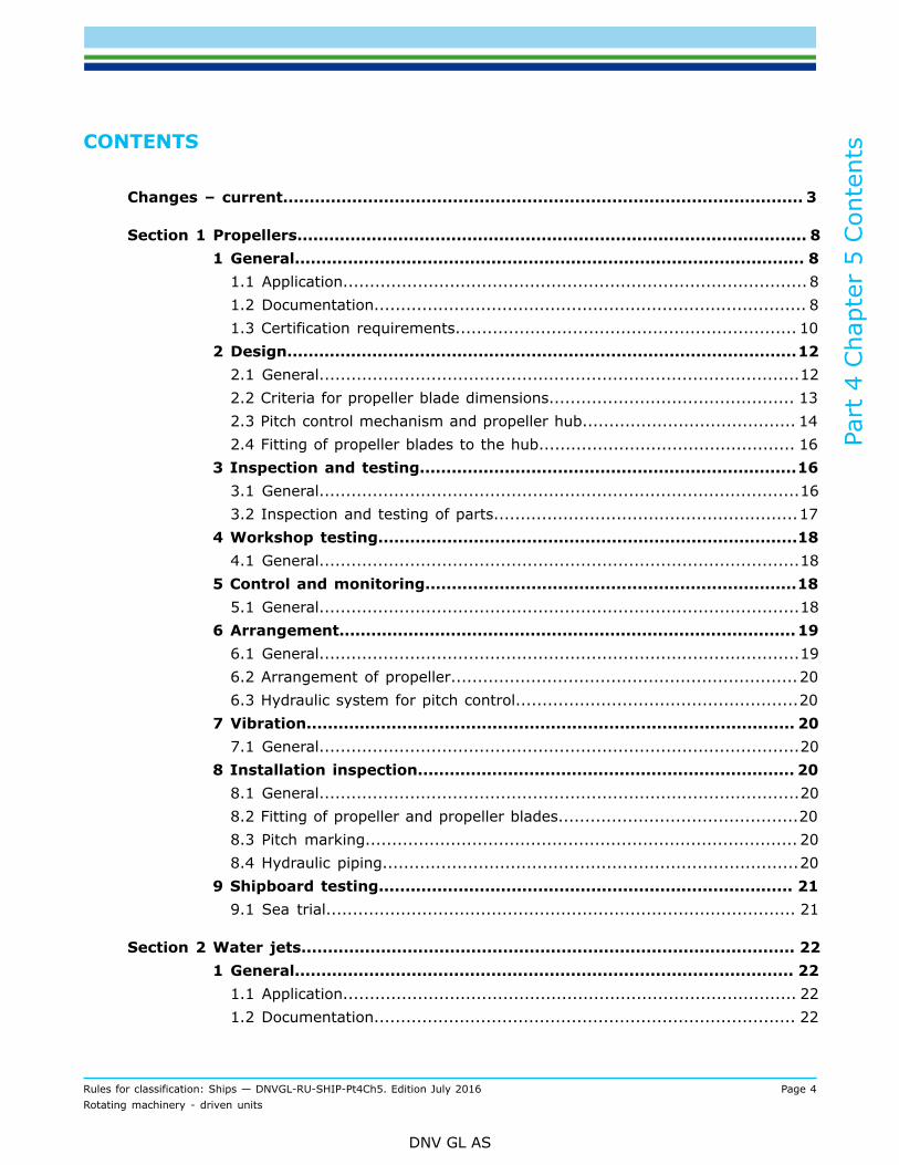
CONTENTS
Changes – current.................................................................................................. 3
Section 1 Propellers................................................................................................ 81 General................................................................................................ 8
1.1 Application....................................................................................... 81.2 Documentation................................................................................. 81.3 Certification requirements................................................................ 10
2 Design................................................................................................122.1 General..........................................................................................122.2 Criteria for propeller blade dimensions.............................................. 132.3 Pitch control mechanism and propeller hub........................................ 142.4 Fitting of propeller blades to the hub................................................ 16
3 Inspection and testing.......................................................................163.1 General..........................................................................................163.2 Inspection and testing of parts.........................................................17
4 Workshop testing...............................................................................184.1 General..........................................................................................18
5 Control and monitoring......................................................................185.1 General..........................................................................................18
6 Arrangement......................................................................................196.1 General..........................................................................................196.2 Arrangement of propeller.................................................................206.3 Hydraulic system for pitch control.....................................................20
7 Vibration............................................................................................ 207.1 General..........................................................................................20
8 Installation inspection....................................................................... 208.1 General..........................................................................................208.2 Fitting of propeller and propeller blades.............................................208.3 Pitch marking................................................................................. 208.4 Hydraulic piping..............................................................................20
9 Shipboard testing.............................................................................. 219.1 Sea trial........................................................................................ 21
Section 2 Water jets............................................................................................. 221 General.............................................................................................. 22
1.1 Application..................................................................................... 221.2 Documentation............................................................................... 22

Part
4 C
hapt
er 5
Con
tent
s
Rules for classification: Ships — DNVGL-RU-SHIP-Pt4Ch5. Edition July 2016 Page 5Rotating machinery - driven units
DNV GL AS
1.3 Certification requirements................................................................ 231.4 Definitions......................................................................................25
2 Design................................................................................................262.1 General..........................................................................................262.2 Design of components..................................................................... 26
3 Inspection and testing.......................................................................273.1 General..........................................................................................273.2 Testing and inspection of parts.........................................................273.3 Assembling.....................................................................................27
4 Workshop testing...............................................................................284.1 General..........................................................................................28
5 Control, alarm, safety functions and indications................................285.1 General..........................................................................................285.2 Monitoring and bridge control...........................................................28
6 Arrangement......................................................................................296.1 General..........................................................................................29
7 Vibration............................................................................................ 307.1 General..........................................................................................30
8 Installation survey.............................................................................308.1 Surveys......................................................................................... 30
9 Shipboard testing.............................................................................. 309.1 General..........................................................................................30
Section 3 Podded and geared thrusters................................................................ 321 General.............................................................................................. 32
1.1 Application..................................................................................... 321.2 Definitions......................................................................................321.3 Documentation............................................................................... 331.4 Certification requirements................................................................ 35
2 Design................................................................................................372.1 General..........................................................................................372.2 Shafting.........................................................................................372.3 Gear transmissions..........................................................................382.4 Azimuth steering gear for thrusters...................................................382.5 Steering column and pod stay and underwater housing........................402.6 Propeller........................................................................................ 402.7 Bearings........................................................................................ 412.8 Lubrication system..........................................................................41
3 Inspection and testing.......................................................................42

Part
4 C
hapt
er 5
Con
tent
s
Rules for classification: Ships — DNVGL-RU-SHIP-Pt4Ch5. Edition July 2016 Page 6Rotating machinery - driven units
DNV GL AS
3.1 General..........................................................................................423.2 Assembling.....................................................................................42
4 Workshop testing...............................................................................424.1 Testing of assembled unit................................................................ 42
5 Control, alarm, safety functions and indication..................................425.1 General..........................................................................................425.2 Bridge control.................................................................................43
6 Arrangement......................................................................................456.1 General..........................................................................................456.2 Propulsion thrusters........................................................................ 46
7 Vibration............................................................................................ 467.1 Torsional vibration...........................................................................46
8 Installation inspection....................................................................... 478.1 Installation onboard........................................................................ 478.2 Install fastening to foundation..........................................................47
9 Shipboard testing.............................................................................. 479.1 Sea trial........................................................................................ 47
Section 4 Compressors..........................................................................................481 General.............................................................................................. 48
1.1 Application..................................................................................... 481.2 Documentation............................................................................... 481.3 Certification required.......................................................................50
2 Workshop testing...............................................................................512.1 General..........................................................................................51
3 Design................................................................................................523.1 General..........................................................................................523.2 Piping and arrangement.................................................................. 523.3 Crankshafts.................................................................................... 533.4 Rotors for non-reciprocating compressors.......................................... 553.5 Rotor casing for non-reciprocating compressors.................................. 55
4 Control and monitoring......................................................................554.1 General..........................................................................................55
5 Arrangement on-board...................................................................... 565.1 General..........................................................................................56
6 Vibration............................................................................................ 566.1 Torsional vibration...........................................................................56
7 Installation inspection....................................................................... 567.1 General..........................................................................................56

Part
4 C
hapt
er 5
Con
tent
s
Rules for classification: Ships — DNVGL-RU-SHIP-Pt4Ch5. Edition July 2016 Page 7Rotating machinery - driven units
DNV GL AS
7.2 Vibration........................................................................................ 57
Changes – historic................................................................................................58

Part
4 C
hapt
er 5
Sec
tion
1
Rules for classification: Ships — DNVGL-RU-SHIP-Pt4Ch5. Edition July 2016 Page 8Rotating machinery - driven units
DNV GL AS
SECTION 1 PROPELLERS
1 General
1.1 Application
1.1.1 The rules in this section apply to propellers intended for propulsion, steering and manoeuvring, subjectto certification.Ch.2 describes all general requirements for rotating machinery and forms the basis for all sections in Ch.3,Ch.4 and Ch.5.
1.1.2 The following items are recognised as parts of the propeller and are subject to approval:
— propeller blades— blade fitting mechanism (e.g. blade bolts - if any)— propeller hub— pitch control mechanism (if any).
For fitting of the propeller to the shaft, see Ch.4 Sec.1.
1.1.3 See Pt.6 Ch.6 Sec.1 concerning propellers for ships with ice strengthening.
1.1.4 See Pt.5 Ch.13 concerning additional requirements for propellers for naval vessels.
1.1.5 See Pt.6 Ch.2 Sec.7 concerning additional requirements related to redundant propulsion.
1.1.6 See Pt.6 Ch.3 Sec.1 and Pt.6 Ch.3 Sec.2 concerning additional requirements related to dynamicpositioning systems.
1.2 Documentation
1.2.1 The builder shall submit the documentation required by Table 1. The documentation shall be reviewedby the Society as a part of the class contract.
Table 1 Documentation requirements
Object Documentation type Additional description Info
C020 - Assembly or arrangementdrawing FI
C030 – Detailed drawing
Detailed geometry, including:
— verification details of fitting of hub topropeller shaft
— hub cap with fins and cap bolts (asapplicable)
— blade fitting arrangement (asapplicable).
Material specification, properties and heattreatment.
APHub
C040 – Design analysis Fitting calculation. FI, R

Part
4 C
hapt
er 5
Sec
tion
1
Rules for classification: Ships — DNVGL-RU-SHIP-Pt4Ch5. Edition July 2016 Page 9Rotating machinery - driven units
DNV GL AS
Object Documentation type Additional description Info
Z162 - Installation manual Shall follow each delivery. FI, R
C030 - Detailed drawingDetailed geometry, including blade flange,as applicable. Material specification,properties and heat treatment.
AP
Blade
C040 – Design analysis
FE calculation (mandatory for specialdesigns), including backgrounddocumentation:
— detailed hydrodynamic calculation— wake field data.
(Blade geometry data file in ASCII format,preferably PFF may be requested).
FI, R
Controllable pitch servomechanism C030 - Detailed drawing
Detailed geometry of all load carryingparts, such as servo cylinder, piston andpiston rod.
Material specification, properties and heattreatment.
AP
S042 - Hydraulic control diagramIncluding permissible operating servopressures, specification of oil filter, andalarm list with setpoint and relay times.
AP
Z161 - Operation manual If pitch adjustment is used as load controlof propeller driver. FI, R
C020 - Assembly or arrangementdrawing FI
C030 - Detailed drawing
Detailed geometry of all load carryingparts, such as crank disc, push pull rod,cross head and sliding shoe.
Material specification, properties and heattreatment.
AP
Controllable pitchmechanism
C040 – Design analysisAnalysis including description of pitchpropeller system is mandatory for newdesign.
FI, R
Control and monitoringsystem
I200 - Control and monitoring systemdocumentation According to Ch.9. AP
AP = For approval; FI = For information; R = On request
1.2.2 For general requirements for documentation, including definition of the info codes, see Pt.1 Ch.3 Sec.2.
1.2.3 For a full definition of the documentation types, see Pt.1 Ch.3 Sec.3.
1.2.4 Relevant design parameters shall be given. As a minimum, the following shall be specified:
— engine power at maximum continuous rating (MCR)— corresponding propeller rotational speed— maximum ship speed— design pressure of hydraulic pitch system (if any)— relevant additional class notations (see [1.1.3] - [1.1.6]).
Part
4 C
hapt
er 5
Sec
tion
1
Rules for classification: Ships — DNVGL-RU-SHIP-Pt4Ch5. Edition July 2016 Page 10Rotating machinery - driven units
DNV GL AS
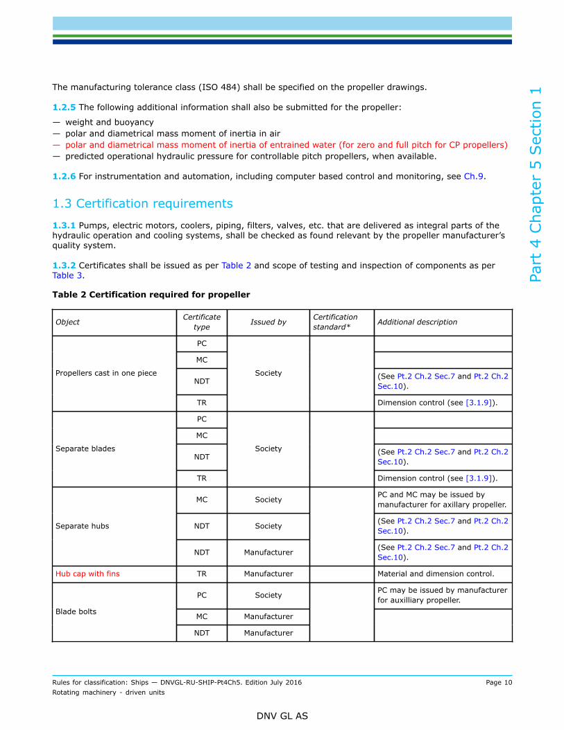
The manufacturing tolerance class (ISO 484) shall be specified on the propeller drawings.
1.2.5 The following additional information shall also be submitted for the propeller:
— weight and buoyancy— polar and diametrical mass moment of inertia in air— polar and diametrical mass moment of inertia of entrained water (for zero and full pitch for CP propellers)— predicted operational hydraulic pressure for controllable pitch propellers, when available.
1.2.6 For instrumentation and automation, including computer based control and monitoring, see Ch.9.
1.3 Certification requirements
1.3.1 Pumps, electric motors, coolers, piping, filters, valves, etc. that are delivered as integral parts of thehydraulic operation and cooling systems, shall be checked as found relevant by the propeller manufacturer’squality system.
1.3.2 Certificates shall be issued as per Table 2 and scope of testing and inspection of components as perTable 3.
Table 2 Certification required for propeller
Object Certificatetype Issued by Certification
standard* Additional description
PC
MC
NDT (See Pt.2 Ch.2 Sec.7 and Pt.2 Ch.2Sec.10).
Propellers cast in one piece
TR
Society
Dimension control (see [3.1.9]).
PC
MC
NDT (See Pt.2 Ch.2 Sec.7 and Pt.2 Ch.2Sec.10).
Separate blades
TR
Society
Dimension control (see [3.1.9]).
MC Society PC and MC may be issued bymanufacturer for axillary propeller.
NDT Society (See Pt.2 Ch.2 Sec.7 and Pt.2 Ch.2Sec.10).Separate hubs
NDT Manufacturer (See Pt.2 Ch.2 Sec.7 and Pt.2 Ch.2Sec.10).
Hub cap with fins TR Manufacturer Material and dimension control.
PC Society PC may be issued by manufacturerfor auxilliary propeller.
MC ManufacturerBlade bolts
NDT Manufacturer

Part
4 C
hapt
er 5
Sec
tion
1
Rules for classification: Ships — DNVGL-RU-SHIP-Pt4Ch5. Edition July 2016 Page 11Rotating machinery - driven units
DNV GL AS
Object Certificatetype Issued by Certification
standard* Additional description
MC
Crank disc, push pull rod, servocylinder and cross head.
Other parts of pitching mechanismupon request.
Controllable pitch mechanism
NDT
ManufacturerNDT shall cover highly stressedareas, such as blade bolts, crankdisk fillet, threads of push-pullrods, etc.
Pitch control and monitoringsystem PC Society See Ch.9.
PC = product cert
MC = material cert
TR = test report
TA = Type approval
NDT = NDT report
*Unless otherwise specified the certification standard is the Society rules.
1.3.3 For general certification requirements, see Pt.1 Ch.3 Sec.4.
1.3.4 For a definition of the certification types, see Pt.1 Ch.3 Sec.5.
1.3.5 The surveyor shall do visual inspection of parts. Visual inspection shall include random dimensionalcheck with emphasis on critical dimensions, tolerances and stress raisers.Manufacturer’s measurement report shall be presented for main items and shall be available upon request forminor components.Manufacturer’s survey report shall be available upon request.
Table 3 Testing and inspection of components
ComponentMaterial test (chemicalcomposition andmechanical properties)
Magneticparticleinspection ordye penetrant
Visual and dimensionalinspection
Propellers cast in one piece Society Society Society1)
Separate blades Society Society Society1)
Separate hubs Society or manufacturer2) Manufacturer3) Society or manufacturer2)
Hub cap with fins Manufacturer
Blade bolts Society or manufacturer2) Manufacturer Manufacturer
Crank disc, push pull rod, servo cylinderand cross head. Other parts of pitchingmechanism when found necessary
Manufacturer Manufacturer4) Manufacturer
The propeller shall be delivered with a Society’s certificate, see [1.1.1]. Reference is also given to [1.1.2].

Part
4 C
hapt
er 5
Sec
tion
1
Rules for classification: Ships — DNVGL-RU-SHIP-Pt4Ch5. Edition July 2016 Page 12Rotating machinery - driven units
DNV GL AS
ComponentMaterial test (chemicalcomposition andmechanical properties)
Magneticparticleinspection ordye penetrant
Visual and dimensionalinspection
1) See also [3.1.9]2) The Society if propulsion.3) Only required in A and C zones (see Pt.2 Ch.2 Sec.8 and Pt.2 Ch.2 Sec.11 [3]).4) Only required in highly stressed areas, such as blade bolts, crank disk fillet, threads of push-pull rods, etc.
2 Design
2.1 General
2.1.1 Materials for propellers shall comply with the requirements in Pt.2 Ch.1 and Pt.2 Ch.2.For other materials, particulars of mechanical properties and chemical compositions shall be submitted tothe Society. Fatigue properties different from the ones given in Table 4 may be accepted, provided sufficientdocumentation is presented.
Table 4 Material properties
MaterialMaterial constant
U1 [N/mm2]Material constant
U2 [-]Minimum yield strength
σy [N/mm2]Minimum tensile strength
σB [N/mm2]
Mn-Bronze, CU1(High tensile brass)
55 0.15 175 440
Mn-Ni-Bronze, CU2(High tensile brass)
55 0.15 175 520
Ni-Al-Bronze, CU3 80 0.18 245 590
Mn-Al-Bronze, CU4 75 0.18 275 630
Martensitic stainless steel(12Cr 1Ni)
60 0.20 440 590
Martensitic stainless steel(13Cr 4Ni/13Cr 6Ni)
65 0.20 550 750
Martensitic stainless steel(16Cr 5Ni)
70 0.20 540 760
Austenitic stainless steel(19Cr 10Ni)
55 0.23 180 440
Forged steel and other materials shall be especially considered.
Guidance note:Fatigue properties in sea water U1 (fatigue strength amplitude) and U2 (relative reduction of fatigue strength with increasing meanstress) may be documented in accordance with the following recommended testing procedure:
— Material specimen without notches should be tested in “sea water”. The specimen should be welded, according to an approvedrepair method, including post heat treatment as applicable. Surface roughness should be as for finished propellers. Materialproperties and chemical composition should be representative for the minimum material requirements.

Part
4 C
hapt
er 5
Sec
tion
1
Rules for classification: Ships — DNVGL-RU-SHIP-Pt4Ch5. Edition July 2016 Page 13Rotating machinery - driven units
DNV GL AS
— Bending of flat bars is preferred, but testing with rotating bending is also acceptable.
— Thickness of specimen should be at least 25 mm.
— Number of cycles to be at least 107 at a bending frequency not higher than 5 Hz.
— Number of tests should be minimum 25. Specimen shall be taken from at least two separate material charges.
— Testing should be performed according to the “Staircase method”.
U1 (N/mm2) to be taken as:
where:
UE7 = average fatigue amplitude [N/mm2], corresponding to 107 cycles at zero mean stress (stress ratio, R = -1)
σE7 = corresponding standard deviation [N/mm2].
The factor of 1.3 reflects a correction related to tested number of cycles vs. the expected number of cycles experienced during aships life time.The factor of 2.0 is chosen to account for the scatter of fatigue strength.In case U2 should be documented, additional testing should be carried out as above, with a stress ratio, R = 0.
---e-n-d---o-f---g-u-i-d-a-n-c-e---n-o-t-e---
2.1.2 The requirements given in [2.2], [2.3], and [2.4] apply to all propellers of conventional design andarrangement, unless otherwise explicitly stated. For propellers not recognised as conventional by the Society(e.g. surface piercing propellers, tip fin propellers, cycloidal propellers etc.), the approval shall be based onspecial consideration.
2.1.3 The combination of materials shall be such as to minimise galvanic corrosion.
2.1.4 The surface of the hub, conical bores, fillets and blades shall be smoothly finished.
2.2 Criteria for propeller blade dimensions
2.2.1 The following load conditions shall be considered:
a) High cycle dynamic stresses (> 108 cycles) due to rotational propeller load variation in normal, aheadoperation.
b) Low cycle dynamic stresses (< 106 cycles) due to propeller load variations in a seaway, manoeuvres,starting and stopping, reversing, repetitive ice shock loads etc. shall also be considered when dynamicstresses are not dominated by high cycle load variations, e.g. for propellers for which turning directionmay be reversed and propellers running in undisturbed axial inflow.
Guidance note:Class guideline DNVGL-CG-0039 offers detailed methods on how to assess the minimum safety factors in Table 5 for these loadconditions.Alternative methods may also be considered on the basis of equivalence.
---e-n-d---o-f---g-u-i-d-a-n-c-e---n-o-t-e---
2.2.2 The propeller blades shall be designed with the minimum safety factors as given in Table 5, seealso guidance note in [2.2.1]. The safety factors reflect the expected inaccuracies in the methods used forpredictions of loads and stress calculations, as well as the influence of allowable material defects.It is on the condition that manufacturing tolerance class I or S is specified according to ISO484 for propulsionpropellers. (Tolerance class II or better for other propellers.)Otherwise higher safety factors may be required, based upon special consideration.

Part
4 C
hapt
er 5
Sec
tion
1
Rules for classification: Ships — DNVGL-RU-SHIP-Pt4Ch5. Edition July 2016 Page 14Rotating machinery - driven units
DNV GL AS
Table 5 Minimum safety factors for propeller blades
Load conditionApplication Considered Section
Static Low cycle fatigue High cycle fatigue
At root section - - 1.8All propellers, exclusive tunnel thrusters
At 0.6R - - 1.6
Reversible direction of rotation,exclusive tunnel thrusters At 0.8R - 1.5 -
Tunnel thrusters At root section 2.2 - -
2.2.3 Somewhat lower safety factors than given in Table 5 may be accepted after special consideration ifdynamic stresses are documented by means of reliable measurements and/or advanced calculation method.
2.2.4 Blade root fillet shall be designed in order to maintain a safety factor in the fillet as required for theroot section. Fillets with constant radius of 75% of root thickness, or multi-radius fillets of a “constant stress”design are considered to comply with this requirement.
2.2.5 For calculation of the blade stress of special propeller designs such as tip fin propellers, special profiles,etc., FE calculation shall be submitted with documented details of the hydrodynamic loads.For calculation of the blade stress of these special propeller designs, in addition to the documents to besubmitted according to [1.2], a blade geometry data file (ASCII format, preferably PFF) shall be submitted tothe Society. Supplementary information for propellers of special designs can be requested by the Society.
2.2.6 If the propeller is subjected to an essential wear e.g. by abrasion in tidal flats or dredgers, a wearaddition shall be provided to the thickness determined according to class requirements to achieve anequivalent lifetime.
2.2.7 If the propeller of azimuthing thruster is subjected to highly oblique inflow in transient conditions suchas crash stop manoeuvring, the propeller blade shall be strengthened accordingly.
2.2.8 Regarding devices for improving propulsion efficiency, the rules for classification of ships Pt.3 Hull, hasto be observed.
2.3 Pitch control mechanism and propeller hub
2.3.1 Mechanical components of a pitch control system and propeller hub shall be able to withstand thestatic loads with the safety factor against yield as specified in Table 6.
Table 6 Minimum safety factors for static strength of propeller hub, pitch mechanism and bladefitting mechanism
Load condition Required safety factor
Load transmitted when two of the blades are prevented from pitching (servo force acting ontwo blades) 1.0
Load transmitted when a propeller blade is exposed to maximum hydrodynamic load 2.0
Load corresponding to maximum servo pressure for strengthening the servo cylinder 2.0
Load corresponding to maximum servo pressure, with the load evenly distributed on allblades 1.3

Part
4 C
hapt
er 5
Sec
tion
1
Rules for classification: Ships — DNVGL-RU-SHIP-Pt4Ch5. Edition July 2016 Page 15Rotating machinery - driven units
DNV GL AS
Guidance note:The latter load case is dimensioning for push-pull rods.
---e-n-d---o-f---g-u-i-d-a-n-c-e---n-o-t-e---
2.3.2 Safety factors for static load conditions reflect the risk and criticality related to the specified loadconditions, as well as the expected prediction quality of the acting loads. The minimum safety factors shallbe against yielding, and shall be applied on acting load. Local geometrical stress concentrations may beneglected. Stresses referred to are equivalent stresses. It is provided that stresses are predicted according togood engineering practice.
2.3.3 Maximum servo force (servo pressure corresponding to set point to safety valve) shall be applied in thecalculations. Guide pin is assumed to be located in the most critical position.
2.3.4 Unless the propeller is intended for auxiliary purposes only, fatigue strength of pitch mechanism andpropeller hub shall be considered taking the load conditions specified in Table 7 into account:
Table 7 Minimum safety factors for fatigue strength of propeller hub and pitch mechanism
Load condition Required safety factor
Start and stop of propeller 1.5
Change of pitch setting in normal operating condition 1.5
Rotational load variation of propeller in normal, ahead operation (for propellersintended for propulsion only). 1.5
2.3.5 Fatigue strength related to each load condition can be calculated separately.
2.3.6 Number of cycles shall correspond to a realistic number of load variations, corresponding to thedescribed condition.
2.3.7 Safety factors for dynamic load conditions reflect the risk and criticality related to the specified loadconditions, as well as the expected prediction quality of the acting loads and fatigue strength of material.Safety factor shall be applied on acting dynamic load vs. fatigue strength of material. Influence of stressconcentrations shall be taken into account in fatigue calculation. Stresses referred to shall be principalstresses. It is presumed that stresses and fatigue strength are predicted according to good engineeringpractice.
Guidance note:Class guideline DNVGL-CG-0039 offers more information on how to assess the minimum safety factors in Table 5 for these loadconditions.Alternative methods may also be considered on the basis of equivalence.
---e-n-d---o-f---g-u-i-d-a-n-c-e---n-o-t-e---
2.3.8 The design shall be such that reasonably low stress concentrations are ensured.
2.3.9 For shrink fitted propellers, hub thickness shall be sufficient to avoid stresses from the dynamic loadingof propeller blades influencing significantly on the shrink fit and vice versa.
Guidance note:In order to provide the above statement a hub thickness in way of propeller blade corresponding to 70% of the required thicknessof the propeller blade root section is considered enough as a minimum.
---e-n-d---o-f---g-u-i-d-a-n-c-e---n-o-t-e---

Part
4 C
hapt
er 5
Sec
tion
1
Rules for classification: Ships — DNVGL-RU-SHIP-Pt4Ch5. Edition July 2016 Page 16Rotating machinery - driven units
DNV GL AS
2.3.10 The degree of filtration of hydraulic oil shall correspond to maximum allowable particle size in thesystem or better. In addition, the selection and arrangement of filters shall provide for an uninterruptedsupply with filtered oil, also during filter cleaning or exchange.
Guidance note:Specification of a pressure filter for maintaining suitable fluid cleanliness may be 16/14/11 according to ISO 4406:1999 and β6-7 (c)
= 200 according to ISO 16889:2008.
---e-n-d---o-f---g-u-i-d-a-n-c-e---n-o-t-e---
2.3.11 For general design requirements for piping and ancillary equipment such as pipes, pumps, filters andcoolers see Ch.6 and Ch.7, as found applicable.
2.3.12 If necessary for corrosion protection, a hub cap with sufficient strength to protect the shaft effectivelyfrom water ingress shall be fitted. If hub cap with fins are mounted any damage of the fins shall not harm theintegrity of the cap.
Guidance note:The hub cap should be thicker than the fin.
---e-n-d---o-f---g-u-i-d-a-n-c-e---n-o-t-e---
2.4 Fitting of propeller blades to the hub
2.4.1 The pre-tensioning of the blade bolts shall ensure friction forces sufficient to prevent sliding of thepropeller flange with a safety factor greater than 1.0 when the propeller is exposed to forces as described inTable 6 If shear pins are fitted, the sum of friction and shear forces shall be considered. The blade retainingbolts shall be tightened in a controlled way to ensure an appropriate pretension. Pretension stress in theminimum section of the blade bolts shall be in the range of 50 to 70% of the bolt-material yield strength ormaximum 56% of the tensile strength, whichever is the least. During operation any blade opening or loss ofbolt pretension shall be prevented. The blade bolt stress shall not exceed yield strength of the bolt material.
2.4.2 The blade bolt pre-stress shall be high enough to ensure that a certain minimum surface pressurebetween mating surfaces is obtained in all permissible operating conditions.
2.4.3 High cycle dynamic stress amplitudes in the minimum thread section of the blade bolts for propellersintended for propulsion shall fulfil the following criterion:
where:
S = safety factor, not to be less than 1.5σA = dynamic stress amplitudeU = allowable nominal stress amplitude in the threaded area, 35 N/mm2 for machined threads and 60
N/mm2 for rolled threads.
2.4.4 Other means of propeller blade fitting mechanisms shall be especially considered.
3 Inspection and testing
3.1 General
3.1.1 Blade bolt pre-tensioning shall be carried out in the presence of a surveyor.

Part
4 C
hapt
er 5
Sec
tion
1
Rules for classification: Ships — DNVGL-RU-SHIP-Pt4Ch5. Edition July 2016 Page 17Rotating machinery - driven units
DNV GL AS
3.1.2 All tests and inspections in [3.1.4] to [3.1.7] shall be carried out in the presence of a surveyor.
3.1.3 For controllable pitch propellers, all connections shall be properly sealed.
3.1.4 For controllable pitch propellers intended for propulsion, the following pitch settings shall, as aminimum, be properly marked on the hub and blade flange:
— pitch at 70% radius is zero— maximum pitch ahead (pitch limited by mechanical pitch stopper)— maximum pitch astern (pitch limited by mechanical pitch stopper).
The correctness of pitch marks and the mechanical feedback of pitch setting shall be verified by the Society.
3.1.5 The function of the pitch stoppers shall be demonstrated. If pitch stoppers are located outside of thehub, it shall be verified by the Society that maximum travel in each direction is less than inside the propellerhub.
3.1.6 After assembly, the complete servo system shall be properly flushed.
3.1.7 The complete controllable pitch propeller system shall be function tested and pressure tested asfollows:
— hydraulic pitch control to 1.5 times design pressure— tightness of propeller subject to 1 bar.
3.1.8 For hub caps serving as corrosion protection a tightness test shall be carried out.
3.1.9 The propeller blades shall be manufactured according to the specified tolerance class (ISO 484).As a minimum, verification of the following is required:
— surface finish— pitch (local and mean pitch)— thickness and length of blade sections— form of blade sections— location of blades, reference line and blade contour— balancing (see also [4.1])— for propellers running in nozzle or tunnel:
— extreme radius of blades (for controllable pitch propellers with outer section at zero pitch).
See also [2.1.4].For verification of blade edge thickness for ice classed propellers, see also: Pt.6 Ch.6.
Guidance note:Verification of blade section form may include the use of edge templates as specified for manufacturing tolerance classes S and I inISO 484.Equivalent methods can be accepted, for instance the use of multi-axial milling machines, which have proven to be capable ofproducing the specified geometry with such an accuracy that only a slight grinding is necessary to obtain the specified surfacefinish.
---e-n-d---o-f---g-u-i-d-a-n-c-e---n-o-t-e---
3.2 Inspection and testing of parts
3.2.1 Certificates shall be provided as required in Table 2.

Part
4 C
hapt
er 5
Sec
tion
1
Rules for classification: Ships — DNVGL-RU-SHIP-Pt4Ch5. Edition July 2016 Page 18Rotating machinery - driven units
DNV GL AS
3.2.2 With respect to non-destructive testing for detection of surface defects, the following acceptancecriteria apply:
— for propeller blades and hubs, the criteria given in Pt.2 Ch.2 Sec.8 and Pt.2 Ch.2 Sec.11 apply— no defects are accepted in highly stressed areas of components in the pitching mechanism.
4 Workshop testing
4.1 General
4.1.1 The complete propeller shall be statically balanced in accordance with specified ISO 484 tolerance class(or equivalent) in presence of a surveyor. Dynamic balancing shall be carried out for propulsion propellerswith tip speed exceeding 60 m/s. The manufacturer shall demonstrate that the assembled propeller shall bewithin the specified limits.
Guidance note:For built-up propellers, the required static balancing may be replaced by an individual control of blade weight and gravity centreposition.
---e-n-d---o-f---g-u-i-d-a-n-c-e---n-o-t-e---
5 Control and monitoring
5.1 General
5.1.1 For controllable pitch propellers, control and monitoring systems shall comply with the requirements ofCh.9.
5.1.2 Pitch adjustment shall not be used as load control system of prime mover, unless the propeller systemis especially designed for this purpose.
5.1.3 A local control stand for pitch control shall be arranged.
5.1.4 Instrumentation and alarms shall be provided according to Table 8, if not otherwise approved.
Table 8 Control and monitoring of propeller
System/Item
Gr 1Indication
alarm
load reduction
Gr 2Automatic
start ofstandby pump
with alarm
Gr 3Shutdownwith alarm Comments
1.0 Pitch, speed and direction of rotation
Propeller rotational speed IR
Direction of rotation forreversible propellers IR

Part
4 C
hapt
er 5
Sec
tion
1
Rules for classification: Ships — DNVGL-RU-SHIP-Pt4Ch5. Edition July 2016 Page 19Rotating machinery - driven units
DNV GL AS
System/Item
Gr 1Indication
alarm
load reduction
Gr 2Automatic
start ofstandby pump
with alarm
Gr 3Shutdownwith alarm Comments
Propeller pitch for CP-propellers IL, IR
For propulsion, the following pitchsettings shall be marked on the localpitch indicator:
— Mechanical pitch limits aheadand astern, pitch at full aheadrunning, maximum astern pitchand pitch at zero thrust.
2.0 Servo oil for CP-propeller
Pressure IL, IR, LA AS1) The indicators shall be able to showsudden peaks in servo pressure.
Level IL, LA
Differential pressure over filter HA 2)
Gr 1 = Sensor(s) for indication, alarm, load reduction (common sensor permitted but with different set points andalarm shall be activated before any load reduction)
Gr 2 = Sensor for automatic start of standby pump
Gr 3 = Sensor for shutdown
IL = Local indication (presentation of values), in vicinity of the monitored component
IR = Remote indication (presentation of values), in engine control room or another centralized control station suchas the local platform/manoeuvring console
A = Alarm activated for logical value
LA = Alarm for low value
HA = Alarm for high value
AS = Automatic start of standby pump with corresponding alarm
LR = Load reduction, either manual or automatic, with corresponding alarm, either slow down (r/min reduction) oralternative means of load reduction (e.g. pitch reduction), whichever is relevant
SH = Shut down with corresponding alarm. May be manually (request for shut down) or automatically executed ifnot explicitly stated above.
For definitions of load reduction (LR) and shut down (SH), see Ch.1.
1) To be provided when standby pump is required, see [6.3.1].2) Applies only to propulsion propellers.
6 Arrangement
6.1 General
6.1.1 Bolts and nuts shall be properly secured, see [8.2.3].

Part
4 C
hapt
er 5
Sec
tion
1
Rules for classification: Ships — DNVGL-RU-SHIP-Pt4Ch5. Edition July 2016 Page 20Rotating machinery - driven units
DNV GL AS
6.2 Arrangement of propeller
6.2.1 The arrangement and design of the propeller shall be such that satisfactory performance is maintainedunder all operating conditions.
6.2.2 The arrangement of attached free-wheeling propellers shall be especially considered.
6.3 Hydraulic system for pitch control
6.3.1 Unless the propeller is intended for auxiliary purposes only, for single propulsion plants where thepitch-control mechanism is operated hydraulically, at least two mutually independent, power-driven pumpsets shall be installed.
6.3.2 For general requirements with respect to hydraulic systems, see Ch.6 Sec.5 [8.1].
7 Vibration
7.1 General
7.1.1 Not applicable.
8 Installation inspection
8.1 General
8.1.1 Installation of external components shall be carried out according to the maker’s specifications.
8.2 Fitting of propeller and propeller blades
8.2.1 For fitting of propeller, see Ch.4 Sec.1.
8.2.2 For blade bolt pre-tensioning, see [3.1.1].
8.2.3 The surveyor shall verify that bolts and nuts are properly secured. In case bolts are fixed by welding, itshall be verified that only regions with low stress levels are affected.
8.3 Pitch marking
8.3.1 For pitch marking, see [3.1.4].
8.4 Hydraulic piping
8.4.1 Pipes shall have a suitable location and be properly clamped. Inspection and testing shall be possible.
8.4.2 The hydraulic system shall be flushed after assembly to a degree of cleanliness as specified by themaker.

Part
4 C
hapt
er 5
Sec
tion
1
Rules for classification: Ships — DNVGL-RU-SHIP-Pt4Ch5. Edition July 2016 Page 21Rotating machinery - driven units
DNV GL AS
8.4.3 System hydraulic oil shall be in accordance with maker's specification.
9 Shipboard testing
9.1 Sea trial
9.1.1 For controllable pitch propellers, the pitch function and the servo pressure shall be demonstrated tothe satisfaction of the surveyor. Also the function of the local pitch control shall be demonstrated, and thecorrectness of local pitch indicator shall be verified.
9.1.2 Unless the propeller is intended for auxiliary purposes only, the pitch behaviour with inactive servo(zero servo pressure) shall be demonstrated to the surveyor during sea trial.
9.1.3 The performance of the propeller shall be tested at both full ahead operation and full astern operation.For fixed pitch propellers reversing shall be tested at maximum permissible astern r/min. For controllablepitch propellers reversing shall be tested at maximum astern pitch of maximum permissible r/min.
9.1.4 For controllable pitch propellers, the function and setting of the safety valve shall be demonstrated tothe satisfaction of the surveyor.
9.1.5 The filter for the servo oil shall be inspected after the sea trial.

Part
4 C
hapt
er 5
Sec
tion
2
Rules for classification: Ships — DNVGL-RU-SHIP-Pt4Ch5. Edition July 2016 Page 22Rotating machinery - driven units
DNV GL AS
SECTION 2 WATER JETS
1 General
1.1 Application
1.1.1 The rules in this section apply to axial water jets intended for main propulsion and steering for alltypes of vessels.
1.1.2 Ch.2 describes all general requirements for rotating machinery and forms the basis for all sections inCh.3, Ch.4, Ch.5 and Ch.10.
1.1.3 Water jet units with main steering function are also regarded as steering gear for the vessel.
1.1.4 Water jet units for auxiliary steering purposes (i.e. not for propulsion) are only subject to classificationafter special consideration.
1.2 Documentation
1.2.1 The manufacturer shall submit the documentation required by Table 1. The documentation shall bereviewed by the Society as a part of the certification contract.
Table 1 Documentation requirements
Object Documentation type Additional description Info
C020 - Assembly or arrangementdrawing Including cross section FI
C040 - Design analysis Impeller thrust, vessel thrust andmaximum reversing forces at crash stop FI
Z100 - SpecificationWater jet pump characteristic, withoperation limits including cavitation limits,see limit as for Table 5
FIWaterjet, fixed;Waterjet, variable
Z100 - Specification
Normal operating parameters that definethe permissible operating conditions, suchas thrust, impeller speed, vessel speed,impeller speed. versus vessel speed, seelimitations in Table 5
FI
Z261 - Test report Non-destructive testing (NDT) FI
C030 - Detailed drawingInput shaft and impeller shaft shallbe documented according to rules forshafting
AP
C020 - Assembly or arrangementdrawing Bearing arrangement with particulars AP
C040 - Design analysis Calculated lifetime of roller bearings AP
Shafting
C030 - Detailed drawing Seal box, if water lubricated FI

Part
4 C
hapt
er 5
Sec
tion
2
Rules for classification: Ships — DNVGL-RU-SHIP-Pt4Ch5. Edition July 2016 Page 23Rotating machinery - driven units
DNV GL AS
Object Documentation type Additional description Info
C030 - Detailed drawingAll bolt connections carrying thrust ortorque, specification of bolt material andtightening procedure (bolt pre-stress)
AP
C030 - Detailed drawing Including NDT specification FIImpeller
C040 - Design analysis Impeller blade strength calculations FI, R
C030 - Detailed drawing With guide vanes FIStator housing
C040 - Design analysis Strength calculations FI, R
C030 – Detail drawing Including bolting APStern flange
C040 – Design analysis Strength calculation FI
C020 - Assembly or arrangementdrawing Including water inlet ducting FI
C030 - Detailed drawing Cross section of unit. FI
C040 - Design analysis Water inlet ducting, hydrodynamic FI
Waterjet casing
C040 - Design analysis Housing strength calculations, see [2.2] FI, R
C020 - Assembly or arrangementdrawing Steering arrangement AP
C040 - Design analysis Strength calculation of the steering andreversing mechanism APReversing arrangement;
Steering arrangement
S042 - Hydraulic control diagram Including relief valve setting and alarm listwith set points AP
Reversing deflectoractuator C030 - Detail drawing AP
Steering deflectoractuator C030 - Detail drawing AP
Control and monitoringsystem
I200 - Control and monitoring systemdocumentation According to Ch.9 AP
AP = For approval; FI = For information; R = On request
1.2.2 For general requirements for documentation, including definition of the info codes, see Pt.1 Ch.3 Sec.2.
1.2.3 For a full definition of the documentation types, see Pt.1 Ch.3 Sec.3.
1.3 Certification requirements
1.3.1 Water jet parts, semi-products or materials shall be certified according to Table 2 and tested accordingto Table 3 and [3.2].
1.3.2 All piping systems shall be properly flushed, in accordance with the manufacturer’s specification. Thisshall be documented by a work certificate.

Part
4 C
hapt
er 5
Sec
tion
2
Rules for classification: Ships — DNVGL-RU-SHIP-Pt4Ch5. Edition July 2016 Page 24Rotating machinery - driven units
DNV GL AS
Table 2 Certification required
Object Certificatetype Issued by Certification
standard* Additional description
Waterjet PC Society
PC Society Required if manufactured by subsupplier
MC ManufacturerImpeller
TR Manufacturer Balancing - See [3.2.4]
Stator housing MC Manufacturer
Impeller housing MC Manufacturer
Shafting MC Manufacturer As required in Ch.4 Sec.1
PC Society Required if manufactured by subsupplierHydraulic actuators for
reversingMC Manufacturer
Other reversing componentsMCNDT
Manufacturer
PC Society Required if manufactured by subsupplierHydraulic actuators for
steeringMC Society
Other steering components MC Manufacturer
Bolts TR Manufacturer
Ducting MC Manufacturer If delivered integral with the waterjet
Control and monitoringsystem PC Society
*Unless otherwise specified the certification standard is the Society rules.
1.3.3 For general certification requirements, see Pt.1 Ch.3 Sec.4.
1.3.4 For a definition of the certification types, see Pt.1 Ch.3 Sec.5.
1.3.5 The surveyor shall do visual inspection of parts. Visual inspection shall include random dimensionalcheck with emphasis on critical dimensions, tolerances and stress raisers.Manufacturer’s measurement report shall be presented for main items and shall be available upon request forminor components.Manufacturer’s survey report shall be available upon request.

Part
4 C
hapt
er 5
Sec
tion
2
Rules for classification: Ships — DNVGL-RU-SHIP-Pt4Ch5. Edition July 2016 Page 25Rotating machinery - driven units
DNV GL AS
Table 3 Testing and inspection of components
Ultra-sonic orX-ray testing
Surface crackdetection 3) Pressure testing Dimensional
inspectionVisual
inspection Other
Impeller Manufacturer Manufacturer Society Manufacturer1)
Statorhousing Manufacturer4) Manufacturer Manufacturer Society
Impellerhousing Manufacturer4) Manufacturer Manufacturer Society
Shafting According to Ch.4 Sec.1
Hydraulicactuators forreversing andsteering 5)
U-S or surface crack detection(manufacturer)4)
Society ormanufacturer2)
Othersteering andreversingcomponents
Manufacturer4) Manufacturer
Bolts
Ducting whendeliveredintegral withthe water jet
Manufacturer Manufacturer Society
1) See [3.2.4].2) Society for steering hydraulic actuators, manufacturer for reversing hydraulic actuators.3) Crack detection in final condition.4) NDT of welds upon request.5) Hydraulic actuator includes cylinder, rod, cylinder end eye and rod end eye.
1.4 Definitions
1.4.1 The following definitions in Table 4 are used in this section.
Table 4 Definitions
Term Definition
ductingwater streaming along the vessel’s bottom and flows into a duct, leading the water to thewater jet. The duct forms an integral part of the vessel hull. It is normally manufactured at thebuilder
hydraulic actuators used for either steering or reversing as the driving force that impose the reversing bucket oracts on the steering nozzle to create a change in the water flow direction
impeller the rotating hub with blades. The impeller is connected to the shaft. The impeller is usually castin one piece. Alternatively, the blades are welded onto the hub
impeller housing the water jet casing surrounding the impeller

Part
4 C
hapt
er 5
Sec
tion
2
Rules for classification: Ships — DNVGL-RU-SHIP-Pt4Ch5. Edition July 2016 Page 26Rotating machinery - driven units
DNV GL AS
Term Definition
reversing bucket
for reversing purposes, the water jet incorporates components that can force its entry intothe water flow thereby turning the water jet discharge to be thrown somewhat forwards. Thiscreates a reversing force that acts on the vessel. The flow is either thrown forwards in an angledirected below the vessel, or to both of the sides of the water jet. The components used forthis purpose is denoted a bucket
stator housingby leading the water flow through a row of stationary vanes downstream of the impeller, theswirl added to the water by the impeller is reduced, and the longitudinal speed of the waterflow is increased. The vanes are usually formed as an integral part of the water jet housing
steering nozzlethe water flow is lead through a passageway that can be tilted horizontally in relation to thevessel's longitudinal axis, thereby changing the direction of the water jet flow. This creates aturning moment used for steering the vessel
2 Design
2.1 General
2.1.1 For general design principles for machinery, see Sec.1 [2].
2.1.2 The water jet unit shall be capable of withstanding the loads imposed by all permissible operatingmodes, including the condition when the inlet of the suction is blocked.
2.1.3 The stresses in water jet components shall be considered based on loads due to the worst permissibleoperating conditions, taking into account:
— hydrodynamic loads, including varying hydrodynamic loads due to water flow disturbances introduced e.g.by the ducting or hull
— vessel accelerations versus water jet r/min.
2.1.4 Harmful impeller cavitation shall not occur when operating at full design speed on a straight course andat designated trim, giving the designed water head above the water intake.
Guidance note:Harmful cavitation in this context is that cavitation which shall reduce shafting system and water jet component lifetime byintroducing vibration or impeller erosion.The water jet may be exposed to operating conditions outside the intended design. Such situations may occur for instancedue to increased vessel weight, increased hull resistance, vessel operating at deeper waters etc. In situations where operationexceeds the design premises, harmful impeller cavitation may occur as a consequence of abnormal water jet flow conditions. Thisphenomenon has showed to be of increasing importance with increasing water jet size.To combat this, the water jet should be designed with reasonable margin for cavitation, and care should be taken to avoid vesseloverweight due to e.g. reasons mentioned in the above. The bigger the water jets are the more important this advice become.
---e-n-d---o-f---g-u-i-d-a-n-c-e---n-o-t-e---
2.1.5 The water jet units shall be provided with inspection facilities for inspection of the shaft and impeller.
2.2 Design of components
2.2.1 The dimensions of the shafts and the shafting components, including bearings, shall comply with therequirements in Ch.4 Sec.1.

Part
4 C
hapt
er 5
Sec
tion
2
Rules for classification: Ships — DNVGL-RU-SHIP-Pt4Ch5. Edition July 2016 Page 27Rotating machinery - driven units
DNV GL AS
2.2.2 The impeller housing and stator housing shall be designed against fatigue, considering impeller pulsesand other flow pulses.
2.2.3 Steering and reversing mechanisms shall be designed taking into account the worst permissibleoperational conditions.
2.2.4 The materials used in the hydraulic actuators shall be suitable for the expected environmentalconditions.
2.2.5 Hydraulic actuators for steering shall comply with the requirements given in the Ch.10.
2.2.6 Hydraulic actuators for reversing shall comply with the requirements given in Ch.6 Sec.5 [8]. However,if the hydraulic system for the reversing actuators is the same as for the steering system, the design and testpressure for the reversing actuators shall be the same as for the steering actuators. Higher nominal stressesmay be accepted for the reversing actuator.
2.2.7 The critical details of the duct and connections to the hull structure shall be designed against extremeloads occurring during crash stop and fatigue considerations related to reversing, steering and impellerpulses.
3 Inspection and testing
3.1 General
3.1.1 The certification principles and the principles of manufacturing survey arrangements (MSA) aredescribed in Pt.1 Ch.1 Sec.4.Regarding material and testing specifications, see Pt.1 Ch.3.
3.1.2 Welding procedures shall be qualified according to a recognised standard or Pt.2.
3.2 Testing and inspection of parts
3.2.1 The inspection and testing described in the following are complementary to Table 3.
3.2.2 The visual inspections by the Society shall include random dimensional check of vital areas such asflange transition radius, bolt holes etc., in addition to the main overall dimensions.
3.2.3 Particulars concerning ducting inspections are stated in [8.1.5].
3.2.4 The impeller shall be statically balanced.Guidance note:VDI standard no. 2060 Quality class 6.3 or ISO 1940/1 Balance Guide G6.3 may be used as reference.
---e-n-d---o-f---g-u-i-d-a-n-c-e---n-o-t-e---
3.3 Assembling
3.3.1 For fitting of the impeller to the shaft, see Ch.4 Sec.1 [2.3] to Ch.4 Sec.1 [2.7].

Part
4 C
hapt
er 5
Sec
tion
2
Rules for classification: Ships — DNVGL-RU-SHIP-Pt4Ch5. Edition July 2016 Page 28Rotating machinery - driven units
DNV GL AS
4 Workshop testing
4.1 General
4.1.1 Not applicable.
5 Control, alarm, safety functions and indications
5.1 General
5.1.1 Systems shall comply with the requirements in Ch.9.
5.2 Monitoring and bridge control
5.2.1 The monitoring of water jets (for propulsion) shall be in accordance with Table 5 in regard to:indications, alarms and requests for slowdown.
Table 5 Control and monitoring of water jets
System/Item
Gr 1Indication
alarm
load reduction
Gr 2Automatic
start of stand-by pump
with alarm
Gr 3Shut downwith alarm Comment
1.0 Steering
Loss of steering and reversingsignal A, LR Request for slow down
2.0 Hydraulic oil
Pressure IR, LA, LR Request for slow down
Level in supply tank IL, LA
3.0 Lubricating oil
Temperature IR, HA
Pressure (if forced lubrication) IR, LA, LR Request for slow down
Level in oil tank (if provided) IL, LA
4.0 Operational limitations1)
The ratio impeller r.p.m versusvessel speed IR, HA, LR Request for slow down
Maximum permissible vesselacceleration exceeded Indication on bridge

Part
4 C
hapt
er 5
Sec
tion
2
Rules for classification: Ships — DNVGL-RU-SHIP-Pt4Ch5. Edition July 2016 Page 29Rotating machinery - driven units
DNV GL AS
System/Item
Gr 1Indication
alarm
load reduction
Gr 2Automatic
start of stand-by pump
with alarm
Gr 3Shut downwith alarm Comment
Gr 1 = Sensor(s) for indication, alarm, load reduction (common sensor permitted but with different set points andalarm shall be activated before any load reduction)
Gr 2 = Sensor for automatic start of standby pump
Gr 3 = Sensor for shutdown
IL = Local indication (presentation of values), in vicinity of the monitored component
IR = Remote indication (presentation of values), in engine control room or another centralized control station suchas the local platform/manoeuvring console
A = Alarm activated for logical value
LA = Alarm for low value
HA = Alarm for high value
AS = Automatic start of standby pump with corresponding alarm
LR = Load reduction, either manual or automatic, with corresponding alarm, either slow down (r/min reduction) oralternative means of load reduction (e. g. pitch reduction), whichever is relevant
SH = Shut down with corresponding alarm. May be manually (request for shut down) or automatically executed ifnot explicitly stated above.
For definitions of load reduction (LR) and shut down (SH), see Ch.1.
1) These requirements are only valid for water jets with inlet diameter in excess of 1 000 mm.
5.2.2 Monitoring and bridge control shall also be in compliance with Ch.9 and Ch.10 Sec.1 [5.5] to Ch.10Sec.1 [5.7].
5.2.3 Frequent corrections in the steering control system, when the vessel is on straight course, shall beavoided if practicable.
Guidance note:The actual corrections should be read preferably by monitoring the control signal. Alternatively, direct measurements onmechanical feedback device from the water jet can be used.
---e-n-d---o-f---g-u-i-d-a-n-c-e---n-o-t-e---
6 Arrangement
6.1 General
6.1.1 The installation and arrangement of the water jet unit with auxiliaries shall comply with themanufacturer’s specification.
6.1.2 Ship external parts of the water jet shall be protected by guard rails or other suitable means.

Part
4 C
hapt
er 5
Sec
tion
2
Rules for classification: Ships — DNVGL-RU-SHIP-Pt4Ch5. Edition July 2016 Page 30Rotating machinery - driven units
DNV GL AS
7 Vibration
7.1 General
7.1.1 For requirements concerning whirling calculations and shaft alignment specification, see Ch.2.
7.1.2 For requirements concerning torsional vibration calculations for water jets, see Ch.2.
8 Installation survey
8.1 Surveys
8.1.1 The fastening of the water jet to the hull and the structural strengthening around the water jet unitwith ducting shall be carried out in agreement with the approved drawings.
8.1.2 Impeller clearances shall be checked after installation and shaft alignment and shall be in accordancewith the manufacturer’s specification.
8.1.3 Normal procedures for shafting apply, see Ch.4 Sec.1 [7].
8.1.4 Thrust bearing axial clearances after installation shall be verified to be in accordance with themanufacturer specification, unless verified during assembly of the water jet.
8.1.5 The ducting shall be manufactured in accordance with drawings and specifications from the waterjet designer. The surfaces shall be smooth and free from sharp edges or buckling that could give raise toturbulence in the water flow and thereby adversely affect water jet operating conditions.
Guidance note:Great care should be taken in assuring that the ducting dimensions agree with the water jet designer’s drawings. The ductingdesigner should be consulted for use of possible dimensional checking equipment, such as templates especially made for thatpurpose.
---e-n-d---o-f---g-u-i-d-a-n-c-e---n-o-t-e---
8.1.6 Pressure testing of piping shall be done according to Ch.6.
9 Shipboard testing
9.1 General
9.1.1 For general requirements related to the testing of control and monitoring, see Ch.9.For testing of steering gear, Ch.10 Sec.1 [9] applies.
9.1.2 Final acceptance of the control system is dependent upon satisfactory results of the harbour testingand the final sea trial, as specified in items [9.1.3], [9.1.4] and [9.1.5].
9.1.3 Attention shall be paid to combinations of operational functions. Testing of all combinations of functionsshall be carried out.
9.1.4 Indication and alarm (if applicable) of operation outside the specified operation limits shall be checked.This applies to acceleration as well as impeller speed versus vessel speed.
Part
4 C
hapt
er 5
Sec
tion
2
Rules for classification: Ships — DNVGL-RU-SHIP-Pt4Ch5. Edition July 2016 Page 31Rotating machinery - driven units
DNV GL AS
9.1.5 The water jet speed versus vessel speed shall be noted and plotted against the manufacturersoperational curves when inlet diameter exceeds 1000 mm. The surveyor shall verify the correct reading ofvalues, and the results shall be submitted to the approval centre after completion of test.

Part
4 C
hapt
er 5
Sec
tion
3
Rules for classification: Ships — DNVGL-RU-SHIP-Pt4Ch5. Edition July 2016 Page 32Rotating machinery - driven units
DNV GL AS
SECTION 3 PODDED AND GEARED THRUSTERS
1 General
1.1 Application
1.1.1 The rules apply to thruster plants intended for propulsion, propulsion and steering, dynamic positioningand, if above 300 kW for auxiliary duty. However, the requirements in [3.2.2], [3.2.3], [5], and [9] apply toall thrusters.The tunnel and other parts, that are welded or bolted to the hull and form a barrier against the ingress ofseawater, shall always be subject to approval, also for auxiliary units of 300 kW or less.Thrusters of unconventional design are evaluated based on equivalence and may be accepted provided thatsafety and reliability can be documented to be equivalent or better than the requirements of this section.
1.1.2 For thrusters that are part of a dynamic positioning system, additional requirements are given in Pt.6Ch.3 Sec.1 and Pt.6 Ch.3 Sec.2.For thrusters that are installed in a vessel with additional class notation RP additional requirements are givenin Pt.6 Ch.2 Sec.7.For thrusters intended for navigation in ice, additional requirements are given in Pt.6 Ch.6.
1.1.3 Ch.2 describes all general requirements for rotating machinery and forms the basis for all sections inCh.3, Ch.4 and Ch.5.
1.1.4 The requirements in [2.4] are specific for steering gear for azimuth thrusters and replace theequivalent requirements in Ch.10 Sec.1, which apply to conventional rudders.However, Ch.10 also gives requirements, depending on vessel type and size, which shall be complied with inaddition to the requirements in [2.4].
1.1.5 For HS, LC and NSC the following rules also apply:
— machinery in general: HSC Code 9.1.1 to 9.1.14, HSC Code 9.7 and 9.8 (passenger craft), and HSC code9.9 (cargo craft)
— propulsion and lift devices: HSC Code 9.6.1 to 9.6.5.
1.2 Definitions1.2.1
Table 1 Definitions
Term Definition
auxiliary thruster is a thruster for all other purposes than propulsion and dynamic positioning
azimuth thruster is capable of providing omni-directional thrust by being rotated around the vertical axis
declared steering anglelimits
are the operational limits in terms of maximum steering angle, or equivalent, according tomanufacturer's guidelines for safe operation, also taking into account the vessel's speed orpropeller torque/speed or other limitation
dynamic positioningthruster
is a thruster that is a part of a dynamic positioning system on board a vessel with a dynamicpositioning class notations, see Pt.6 Ch.3 Sec.2 and Pt.6 Ch.3 Sec.1

Part
4 C
hapt
er 5
Sec
tion
3
Rules for classification: Ships — DNVGL-RU-SHIP-Pt4Ch5. Edition July 2016 Page 33Rotating machinery - driven units
DNV GL AS
Term Definition
geared thruster thruster with a lower gear or lower and upper gear
podded thruster thruster with the prime mover directly attached to the propeller shaft (often called “pod orpodded propulsor”)
propulsion thruster is a thruster that is assigned to propulsion of the vessel. A propulsion thruster may also providesteering function
thrusteris a unit equipped with a propeller or impeller in order to produce thrust and is considered to bethe complete assembly; from the propeller with nozzle (if applicable) to the input shaft at theupper gear or slip ring unit (if applicable)
tunnel thruster thruster mounted in a tunnel for the purpose of providing lateral thrust for the vessel
1.3 Documentation
1.3.1 Documentation shall be submitted as required by Table 2.
Table 2 Documentation requirements
Object Documentation type Additional description Info
C020 - Assembly orarrangement drawing
Arrangement drawing of the thruster unit, including driver andintermediate shafting (yard supply) AP
C020 - Assembly orarrangement drawing
Sectional drawing of the whole thruster unit, including bearingarrangement AP
C020 - Assembly orarrangement drawing Shaft brake/locking device arrangement (if applicable) FI
C040 - Design analysis Shaft brake/locking device capacity calculation (if applicable) FI
C020 - Assembly orarrangement drawing Sealing arrangement for flexibly mounted tunnel thrusters AP
C030 - Detaileddrawing
Sectional drawings including all torque transmitting parts, e.g. shafts,couplings and gears AP
C030 - Detaileddrawing
For podded thrusters: sectional drawing of electric motor includingparticulars of stator-to-housing and rotor-to-shaft connections anddefined air gap with tolerances
AP
C040 - Design analysis Component strength calculation for structural parts FI, R
C040 - Design analysis Torsional vibration calculations (yard supply), see Ch.2 Sec.2 AP
C040 - Design analysis Torsional impact calculations. Applicable if high transient torque inelectric motor drive (e.g. star-delta start), (yard supply), see Ch.2 Sec.2 AP, R
C040 - Design analysis Bearing life time calculations. Applicable if roller bearings FI
Z100 – Specification Material, nominal surface pressure and clearance tolerances in case offluid film bearings. Applicable if plain bearings FI
Thruster
C040 - Design analysis For podded thrusters: heat balance calculation FI

Part
4 C
hapt
er 5
Sec
tion
3
Rules for classification: Ships — DNVGL-RU-SHIP-Pt4Ch5. Edition July 2016 Page 34Rotating machinery - driven units
DNV GL AS
Object Documentation type Additional description Info
S010 - Piping diagram(PD) For podded thrusters: bilge system AP
Z060 – Functionaldescription For podded thrusters: bilge system FI
Z030 –Arrangementplan Steering gear compartment for propulsion thrusters (yard supply) FI
Z050 - Designphilosophy
Operational (design) limitations such as, but not limited to:
— limitations in rotation of azimuth thrusters at high vessel speed— maximum vessel speed for lowering and lifting of retractable units
FI
Z051 - Design basis Maximum forces acting on the thruster unit under the most extremeallowable manoeuvre, including crash stop FI
Z060 – Functionaldescription
Load control system including description of the method used to controlthe load (CP-mechanism, frequency converter etc.) FI, R
Z100 – Specification Specification of torque capacity of off-the-shelf gear transmissions usedin steering motor arrangements (see footnote in [1.4.4]) FI
Z161 - Operationmanual
Operation instruction poster for control and steering of the thruster,including emergency operation. Shall be displayed on the navigationbridge and in the steering gear compartment
AP
Z250 – Procedure Assembling and adjustment procedures regarding gear mesh contact fordrive gears and steering gears FI, R
Z250 – Procedure For propulsion thrusters: crash stop procedure FI
Z051 - Design basis
Maximum start-up torque (KAP factor, see class guideline DNVGL-CG-0036).Does not apply to thrusters which obtain the required scuffing safetyfactor (see Table 3) with a peak torque factor KAP of 1.5 or higher andhave equivalent mass moment of inertia of motor higher than equivalentmass moment of inertia of the propeller
FI
C030 - Detaileddrawing Sectional drawings of slewing bearing and thruster support bearing APFixation
arrangement
Housing andstructuralpart
C030 - Detaileddrawing
Structural drawings (gear housing etc.) and connections to the tunnel ornozzle (if not covered by sectional drawings), including NDT specification AP
Gears Ref to Ch.4 Sec.2 AP
Propeller Ref to Sec.1 AP
Propellershaft seal
C030 - Detaileddrawing AP
Propellernozzle
C030 - Detaileddrawing AP
Steeringcolumn
C030 - Detaileddrawing Including NDT specification AP

Part
4 C
hapt
er 5
Sec
tion
3
Rules for classification: Ships — DNVGL-RU-SHIP-Pt4Ch5. Edition July 2016 Page 35Rotating machinery - driven units
DNV GL AS
Object Documentation type Additional description Info
C020 - Assembly orarrangement drawing Steering gear assembly, including azimuth brake/locking device AP
C030 - Detaileddrawing Including all load transmitting parts AP
S042 - Hydrauliccontrol diagram Including alarm and indicator set points AP
Z060 – Functionaldescription
Description of steering gear function and load limiting devices includingmaximum values FI
Z100 – Specification Load data for azimuth gear, including capacity of azimuth brake FI
Z110 – Data sheetElectrical motor for steering gear (if applicable), including motor ratingaccording to IEC and torque versus speed characteristics of electricalmotor
FI, R
Steeringgearactuator
Z110 – Data sheet Frequency converter set value of parameters, list of alarms, shutdownsand ramp functions (if applicable) FI
Thruster seal C030 - Detaileddrawing Sealing arrangement for steering column, see [2.5] AP
Lubricatingsystem
S010 - Piping diagram(PD) Lubrication oil system including alarm and indicator set points AP
Control andmonitoringsystem
I200 - Control andmonitoring systemdocumentation
AP
AP = For approval; FI = For information; R = On request
1.3.2 For general requirements for documentation, including definition of the info codes, see Pt.1 Ch.3 Sec.2.
1.3.3 For a full definition of the documentation types, see Pt.1 Ch.3 Sec.3.
1.4 Certification requirements
1.4.1 The complete thruster shall be delivered with certificate as required in Table 3 and tested andinspected as required in Table 2. It shall be based on the design approval in [2], the component certificationin [3], the workshop testing in [4] and relevant monitoring equipment in [5].
Table 3 Certification requirements
Object Certificatetype
Issued by Certificationstandard*
Additional description
Thruster PC Society Complete thruster
Underwater housing MC Manufacturer
Inboard housing MC Manufacturer
Outer housing MC Society Non rotating, forming barrier to sea
Steering column or rotatingsupport
MC Society

Part
4 C
hapt
er 5
Sec
tion
3
Rules for classification: Ships — DNVGL-RU-SHIP-Pt4Ch5. Edition July 2016 Page 36Rotating machinery - driven units
DNV GL AS
Object Certificatetype
Issued by Certificationstandard*
Additional description
Propeller nozzle MC Society
Control and monitoringsystems
PC Society — Required for thrusters forpropulsion and dynamicpositioning duty
*Unless otherwise specified the certification standard is the Society rules.
Table 4 Testing and inspection of components
Ultra-sonic orX-ray testing
Surface crackdetection 2) Pressure testing Dimensional
inspectionVisual
inspection Other
Underwaterhousing Manufacturer Society
Inboardhousing Manufacturer Society
Outerhousing Manufacturer Society
Propellernozzle Manufacturer Society
Steeringcolumn orrotatingsupport
Manufacturer1) Manufacturer Society
1) The test certificate shall refer to a recognized standard and approved acceptance levels.2) Surface and crack detection (MPI or dye penetrant) is required in way of zones with stress risers and in welded
connections. The extent and acceptance criteria shall be specified in the documentation submitted for approval.
1.4.2 For general certification requirements, see Pt.1 Ch.3 Sec.4.
1.4.3 For a definition of the certification types, see Pt.1 Ch.3 Sec.5.
1.4.4 Certification requirements are given in the respective references or in this section:
— pinions and wheels for propeller drive, see Ch.4 Sec.2— pinions and wheels for azimuth steering, see Ch.4 Sec.2*
Guidance note:* For propulsion thrusters which have high speed hydraulic motor or electric motor (equivalent to rudder actuator) which iscombined with “off the shelf”, mass produced gear boxes, the certification of the gearboxes may be based on function testingonly, provided that:
— vessel has two or more independent propulsion thrusters
— vessel is fully manoeuvrable with one thruster locked in worst possible condition (other thruster(s) in operation)
— each thruster is provided with two or more steering gear actuators
— the gearboxes shall be conservatively chosen with regard to required safety factors and able to handle all relevant loads forthe steering gear
— easily replaceable.
---e-n-d---o-f---g-u-i-d-a-n-c-e---n-o-t-e---

Part
4 C
hapt
er 5
Sec
tion
3
Rules for classification: Ships — DNVGL-RU-SHIP-Pt4Ch5. Edition July 2016 Page 37Rotating machinery - driven units
DNV GL AS
— shafts, see Ch.4 Sec.1— clutches, see Ch.4 Sec.3— couplings, see Ch.4 Sec.4— propeller, see Sec.1— hydraulic motor for steering (to be handled as a pump), see Ch.6 Sec.6.
1.4.5 Electrical equipment shall be certified as required in Ch.8.
1.4.6 For a definition of the certificate types, see Pt.1 Ch.3
1.4.7 Welds in any part mentioned in [1.4.1], if specified during approval shall be ultrasonic tested. Thesetests shall be carried out at an appropriate stage of the manufacturing process. The test certificate shall referto a recognized standard and approved acceptance levels.
1.4.8 Visual inspection shall be carried out of all parts mentioned in Table 4 and [1.4.4] unless otherwisedefined in a manufacturing survey arrangements (MSA).
1.4.9 Ancillaries, which are not part of the steering gear, such as pumps, electric motors, coolers, piping,filters and valves that are delivered as integral parts of the lubrication, hydraulic operation and coolingsystems of the thruster, shall be subjected to a quality control in accordance with the thruster manufacturer’squality system as found relevant.
2 Design
2.1 General
2.1.1 The thruster shall be capable of withstanding the loads imposed by all allowable operating conditionsincluding effects of thermal expansion elastic deformations.
2.1.2 In-dock inspection of thruster gears shall be made possible either through proper inspection openings,or by other means (e.g. fibre optical instruments) without extensive dismantling.
2.1.3 Podded thruster internals shall be shielded in order to provide safe entrance/accessibility to performnecessary maintenance and inspection without risk of damage neither to equipment nor personnel. Sufficientventilation shall be provided.
2.1.4 For general design requirements for piping and ancillary equipment such as pipes, pumps, filters andcoolers, see Ch.6 and Ch.7, as found applicable.Hydraulic components shall be chosen in consideration of the expected level of contamination the system willbe exposed to during its lifetime.Flange connections for piping systems shall be located as far as practicable outside the podded thruster.Flanges and valves inside podded thrusters shall be arranged to minimise the consequence of leakage, i.e. bydrip trays and leakage drain to safe location.
2.1.5 The cooling system shall be in accordance with Ch.6 Sec.5 [2].
2.1.6 For design and arrangement requirements for electric systems and control systems reference is madeto Ch.10 Sec.1 [5] (for propulsion thrusters only) and Ch.8 and Ch.9.
2.2 Shafting
2.2.1 The dimensions of the shafts and the shafting components shall be in accordance with Ch.4 Sec.1.

Part
4 C
hapt
er 5
Sec
tion
3
Rules for classification: Ships — DNVGL-RU-SHIP-Pt4Ch5. Edition July 2016 Page 38Rotating machinery - driven units
DNV GL AS
For podded thrusters there shall be a sufficient air gap between rotor and stator under all relevant operatingconditions.
2.2.2 A shaft sealing box shall be installed to prevent water from entering into internal parts of the thrusteror into the ship. The sealing arrangement shall protect the steel shafts from seawater, unless corrosion-resistant steel especially approved by the Society is used.For single thruster arrangements, the shaft seal shall be duplicated and means for leakage detection shall beprovided.
2.3 Gear transmissions
2.3.1 Gear transmissions shall be in accordance with the requirements in Ch.4 Sec.2 as far as applicable.The lifetime criteria given in Table 5 shall as a minimum be used for dimensioning the gears in the propellerdrive line.
Table 5 Thruster type and load cycles
Type of thruster Minimum number of input shaft revolutions at full power(NL load cycles)
Propulsion 1) 1·1010
Dynamic positioning 5·108
Auxiliary 5·107
1) For thrusters subject to frequent overload (intermittent load), relevant load and corresponding accumulated numberof load cycles shall be applied, see also Ch.2 Sec.1 [2].
The safety factors SF, SH, SHSS and SS shall be at least as specified in Ch.4 Sec.2 Table 5. The safety factorsfor gears in thrusters for dynamic positioning shall be as for propulsion gears.
2.4 Azimuth steering gear for thrusters
2.4.1 Steering gear for auxiliary and dynamic positioning thrusters need not comply with [2.4.2], [2.4.3],[2.4.4], [2.4.5], [2.4.7], requirements for safety valve set value in [2.4.8], [2.4.10] and [2.4.17].
2.4.2 Steering arrangement for the vessel shall comply with the following requirements:
a) the vessel shall be provided with two steering gears, each with strength and capacity as specified belowb) a single failure shall neither lead to loss of steering of the vessel, nor consequential damage to the
thrusters.
2.4.3 The steering gear for the thruster shall:
a) be capable of turning the thruster from one side to the other at declared steering angle limits at anaverage rotational speed of not less than 2,3 deg/sec with ship running at maximum ahead servicespeed, which shall be demonstrated at sea trial
b) have capacity to turn the thruster from side to side according to steering gear test. See Ch.10 Sec.1[2.4.1] b
c) be capable of bringing the thrusters back to neutral position from any allowable angle at maximumservice speed.
2.4.4 The thrusters shall be prevented from sudden turning in the case of power failure, failure in thesteering control system or any other single failure, except failure in steering column and support bearings.

Part
4 C
hapt
er 5
Sec
tion
3
Rules for classification: Ships — DNVGL-RU-SHIP-Pt4Ch5. Edition July 2016 Page 39Rotating machinery - driven units
DNV GL AS
2.4.5 It shall be possible to bring the thruster to neutral position and lock it to allow it to produce thrust inthe case that its steering gear is inoperative.
2.4.6 Steering gear shall be designed considering all relevant loads from internal and external forces.
2.4.7 Steering gear drivers shall be designed with a capacity not less than 125% of the maximum torqueoccurring during the steering gear test as described in Ch.10 Sec.1 [2.4.1] b). See also [2.4.17] for electromotor rating.
2.4.8 The steering gear arrangement shall be provided with a load limiting device (limiting torque/ pressureas applicable), such as relief valve or frequency converter limiter.The load limiting device shall have a set value not less than 125% of torque occurring during steering geartest as described in Ch.10 Sec.1 [2.4.1] b), however not exceeding the design torque in the system.
2.4.9 Hydraulic systems for steering gears shall not be used for other purposes than steering.For propulsion thrusters the requirements given in Ch.10 Sec.1 [2.10] apply.
Guidance note:Steering hydraulic may share the oil sump with systems for propeller pitch control and/or internal lubrication. This is provided thatimpurity from one system is not transmitted to the other systems and sufficient cooling capacity is available.
---e-n-d---o-f---g-u-i-d-a-n-c-e---n-o-t-e---
2.4.10 Azimuth thrusters designed for reversing the thrust by turning the unit shall be able to do so at aturning rate of minimum 2 r/min.
2.4.11 Azimuth steering gears shall have a margin against self-locking in order to avoid “stick slip” effects.The total drive train efficiency (excluding the driving motor) shall not be less than 0.65.
2.4.12 Azimuth steering gears for dynamically positioning thrusters shall be designed for continuousrunning. See the Pt.6 Ch.3 Sec.1 [6.1] and Pt.6 Ch.3 Sec.2 [6.1].
2.4.13 Steering gear transmissions shall as far as applicable be in accordance with the requirements in Ch.4,regardless of power rating. The steering gear transmission shall be designed considering the relevant loads(see [1.2.1]).
Guidance note:Typically the following load cases shall be considered:
— Maximum torque corresponding to relief valve setting pressure (steering gear design pressure pD) for hydraulic operation,respectively max torque for electric motor operation. This should be considered as a static or low cycle fatigue case (1 000cycles).
— Loads occurring at larger manoeuvre (course changing). This load corresponds to the maximum working pressure pW and willtypically occur in the range from 5 000 to 100 000 times during the vessels lifetime.
— Loads occurring due to course keeping corrections (auto pilot load). This is a high cycle load case and more than 5·107 coursecorrections (load cycles) may be expected during the vessels lifetime.
---e-n-d---o-f---g-u-i-d-a-n-c-e---n-o-t-e---
2.4.14 For reduction gears, the safety factors SF against tooth fracture, SH against pitting, SHSS againstsubsurface fatigue (surface hardened gears only) and SS against scuffing shall be at least as specified inTable 6.

Part
4 C
hapt
er 5
Sec
tion
3
Rules for classification: Ships — DNVGL-RU-SHIP-Pt4Ch5. Edition July 2016 Page 40Rotating machinery - driven units
DNV GL AS
Table 6 Safety factors
SF SH and SHSS SS
Azimuth steering gear
— for surface hardened— for not surface hardened
1.51.5
1.151.0
1.4*1.2*
* Not applicable to slow speed gears (pitch line speed < 2 m/s)
2.4.15 Inspection of azimuth gear and pinion shall be possible either through proper inspection openings orby other means (e.g. fibre optical instruments) without extensive dismantling.
2.4.16 The control system for electro motors driving the steering pinion directly shall be designed to avoidabrupt acceleration and shock loads in mechanical parts.
2.4.17 The electro motor driving the steering gear shall at least have a rating according to IEC60034-1:
a) For electro hydraulic arrangement: S6-25.b) For electro motor directly driving pinion:
— S1 - for torque corresponding to maximum torque occurring during steering gear test, and for theentire speed range including zero rpm.
2.5 Steering column and pod stay and underwater housing
2.5.1 The maximum local stress in the steering column and pod stay shall not exceed 0.8 times the yieldstrength of the material under the most extreme allowable (possible) manoeuvre (see [1.2.1]). FEMcalculation may be required when analytical methods cannot give satisfactory accuracy. The maximumnominal stress shall not exceed 50% of the yield strength.
2.5.2 The steering column and pod stay shall be designed to withstand the fatigue loads arising from thrustvariations and other hydrodynamic loads and accelerations. This applies to parent material as well as to anywelds.
2.5.3 The thruster structure like underwater housings, steering column and pod stay, etc. shall have stiffnesssufficient to avoid harmful deformations which may cause damage to internal shafting, sealing, bearings andgear mesh when subjected to the loads defined in [1.2.1].
2.5.4 The sealing around the steering column and pod stay, at the hull penetration, shall be arranged suchthat any leakage can be detected and drained before water can gain access to water sensitive parts, such asslewing bearing and gears. Existing designs with a proven service record may be accepted with other sealingarrangements.
2.5.5 Podded thrusters shall be provided with a bilge system.The bilge system shall be provided with full redundancy for single podded thruster arrangements.
2.6 Propeller
2.6.1 The propeller and propeller components shall meet the relevant dimensional requirements in Sec.1.See also class guideline DNVGL-CG-0039.

Part
4 C
hapt
er 5
Sec
tion
3
Rules for classification: Ships — DNVGL-RU-SHIP-Pt4Ch5. Edition July 2016 Page 41Rotating machinery - driven units
DNV GL AS
2.6.2 Special attention shall be paid to the sealing for propeller blades, in order to prevent ingress of waterinto the oil system. The sealing shall be designed to ensure that expected lifetime is securely beyond thespecified service intervals.
2.6.3 Controllable pitch mechanism on thrusters that are used in a dynamic positioning system shall bedesigned for continuous operation.
2.7 Bearings
2.7.1 Fluid film bearings shall be designed in accordance with the requirements in Ch.4 Sec.2 [2.7.1].
2.7.2 Ball and roller bearings shall have a minimum L10a (ISO 281) as specified in Ch.4 Sec.2 [2.7.2].
2.8 Lubrication system
2.8.1 The lubrication system shall be designed to provide all bearings, gear meshes and other parts requiringoil with adequate amount of oil for both lubrication and cooling purposes. This shall be maintained under allenvironmental conditions as stated in Ch.1.
2.8.2 Podded thrusters where the total circulated lube oil quantity Voil (in litres) is less than 0.1 × P (P =propeller power in kW) shall have separate lube oil system for each bearing assembly.
2.8.3 The lubrication system shall include:
— an arrangement to take representative oil samples with respect to detecting water and particlecontamination
— if necessary, a cooler to keep the oil temperature within the specified maximum temperature, whenoperating under the worst relevant environmental conditions (see [2.8.1])
— a filter of suitable fineness for gearing, hydraulics and bearings (see [2.7.2]).Guidance note:Specification of a pressure filter for maintaining suitable fluid cleanliness may be 16/14/11 according to ISO 4406:1999 and β6-7 =200 according to ISO 16889:1999.
---e-n-d---o-f---g-u-i-d-a-n-c-e---n-o-t-e---
2.8.4 for propulsion and dynamic positioning thrusters it shall be possible to change or clean filters withoutinterrupting the oil supply.
2.8.5 if forced lubrication is required for operation of the thruster, single propulsion thruster installationshall have a standby pump with immediate action. On vessels with two or more independent and equal sizedpropulsion thrusters, one pump per thruster should be accepted.
2.8.6 For thrusters where wind milling may be detrimental and considered as a normal condition, there shallbe either:
— a shaft brake designed to hold (statically) twice the highest expected wind milling torque, or— one pump available in windmilling condition. This pump shall be additional to any standby pump required
by other parts of rules.
The chosen version shall be automatically activated within 30 s after shutdown.
2.8.7 For thrusters designed to operate at such low rotational shaft speeds that an attached pump (ifneeded) cannot supply sufficient oil pressure, the following shall be accepted:
— either an extra electric oil pump that is activated at a given pressure, or

Part
4 C
hapt
er 5
Sec
tion
3
Rules for classification: Ships — DNVGL-RU-SHIP-Pt4Ch5. Edition July 2016 Page 42Rotating machinery - driven units
DNV GL AS
— 2 electric main pumps of the same capacity, one of which is arranged as a standby pump with immediateaction. These 2 electric pumps shall be supplied from different sides of main distribution.
3 Inspection and testing
3.1 General
3.1.1 The parts in a thruster shall be tested and documented as described in Table 2, Table 3 and Table 4.
3.2 Assembling
3.2.1 Assembling of the drive gears regarding tooth contact shall be in accordance with the approvedprocedure and in the presence of the surveyor. The surveyor shall check access through inspection openings.
3.2.2 For assembling of other elements, see Ch.4 Sec.2 [3.3] and Sec.1 [3.1]. However, for auxiliarythrusters Sec.1 [3.1.1] and Sec.1 [3.1.2] need not be adhered to.
3.2.3 For propeller fitting, see Ch.4 Sec.1.
4 Workshop testing
4.1 Testing of assembled unit
4.1.1 For gear mesh checking, see Ch.4 Sec.2 [4.2] unless another procedure is approved.
4.1.2 For clutch operation, see Ch.4 Sec.2 [4.2].
4.1.3 All hydraulic systems for steering, lubrication and pitch control shall be function and pressure tested.For the steering system the test pressure shall be 1.5 times the design pressure pD as required in Ch.10Sec.1.For other hydraulic systems the test pressure shall be as required in Ch.6 Sec.6. Regarding function testingof controllable pitch propellers, see Sec.1 [3.1].
4.1.4 The thruster unit shall be subjected to leak testing (internal pressure, soap water test or similar).
4.1.5 Testing of electrical equipment such as motors and frequency converters shall comply with Ch.8.
4.1.6 Testing of instrumentation and control systems shall comply with Ch.9.
5 Control, alarm, safety functions and indication
5.1 General
5.1.1 For instrumentation and automation, including computer based control and monitoring, therequirements in this sub-section item are additional to those given in Ch.9.
5.1.2 For additional requirements to vessels with dynamic positioning class notations, see Pt.6 Ch.3 Sec.2and Pt.6 Ch.3 Sec.1.

Part
4 C
hapt
er 5
Sec
tion
3
Rules for classification: Ships — DNVGL-RU-SHIP-Pt4Ch5. Edition July 2016 Page 43Rotating machinery - driven units
DNV GL AS
5.1.3 Alarms and indications shall be initiated, as applicable, for the faults given in Table 7. For electro-driven propulsion thrusters see also Ch.8 Sec.12 [1.6.4].For steering gear see also Ch.10 Sec.1 Table 14.Additionally, an alarm shall be initiated on the bridge in case of power failure of the alarm, control and safetysystem as required in Ch.9 Sec.2 [2.1].
5.1.4 Any alarm condition in the thruster plant shall initiate an alarm on the bridge with individual or group-wise indication. For HS, LC and NSC, all alarms shall have individual indication on the bridge.The alarm indicators on the bridge shall be readily observed at the position from which the vessel iscontrolled and navigated.
5.1.5 Essential and important sensors and components which are not easily replaceable shall be duplicated.
5.2 Bridge control
5.2.1 It shall be possible to stop the propeller from the bridge by means of a system independent of theremote control system.If the independent stop facility is arranged as an emergency stop push button, this shall be arranged inaccordance with Ch.8 Sec.2 [8.4].
Table 7 Control and monitoring of thrusters
System/Item
Gr 1Indication
alarm
load
reduction
Gr 2Automatic
start ofstand-
by pumpwith alarm
Gr 3Shut downwith alarm Comment
1.0 Lubricating oil
Pressure IL2), LA AS1) If forced lubrication oil system
Temperature IL, HA2)
Level IL, LA
2.0 Steering system
Azimuth angle IL
Hydraulic oil pressure IL, LA
Hydraulic oil supply tank level IL, LA
Hydraulic pump motor overload,power and phase failure A Applicable to power units on propulsion
thrusters
Azimuth brake engaged 5) IR If applicable. Manual release shall bepossible. Additional indication on bridge
Interlocking of actuators 4) A See Ch.10 Sec.1 [5.7.4]. Identification offailed system
3.0 Pitch, speed and direction of rotation
Propeller r/min IR Running indication for constant speedpropellers

Part
4 C
hapt
er 5
Sec
tion
3
Rules for classification: Ships — DNVGL-RU-SHIP-Pt4Ch5. Edition July 2016 Page 44Rotating machinery - driven units
DNV GL AS
System/Item
Gr 1Indication
alarm
load
reduction
Gr 2Automatic
start ofstand-
by pumpwith alarm
Gr 3Shut downwith alarm Comment
Direction of rotation for reversiblePropellers
IR
Propeller pitch for CP-propellers IL, IR
For main propulsion, the following pitchsettings shall be marked on the local pitchindicator:
Mechanical pitch limits ahead and astern,pitch at full ahead running, maximumastern pitch and pitch at zero thrust.
For auxiliary and dynpos thrusters; max.,min. and zero pitch is sufficient
4.0 Servo oil for CP-propeller
Pressure IL, LA AS7)
Level IL, LA2)
Differential pressure over filter HA Applicable for propulsion thrusters
5.0 Electrical prime mover 6)
Load (torque)2) IR, HA3) Additional indication on bridge
6.0 Bilge system
Level HA For dry pods

Part
4 C
hapt
er 5
Sec
tion
3
Rules for classification: Ships — DNVGL-RU-SHIP-Pt4Ch5. Edition July 2016 Page 45Rotating machinery - driven units
DNV GL AS
System/Item
Gr 1Indication
alarm
load
reduction
Gr 2Automatic
start ofstand-
by pumpwith alarm
Gr 3Shut downwith alarm Comment
Gr 1 = Sensor(s) for indication, alarm, load reduction (common sensor permitted but with different set points andalarm shall be activated before any load reduction)
Gr 2 = Sensor for automatic start of standby pump
Gr 3 = Sensor for shutdown
IL = Local indication (presentation of values), in vicinity of the monitored component
IR = Remote indication (presentation of values), in engine control room or another centralized control station suchas the local platform/manoeuvring console
A = Alarm activated for logical value
LA = Alarm for low value
HA = Alarm for high value
AS = Automatic start of standby pump with corresponding alarm
LR = Load reduction, either manual or automatic, with corresponding alarm, either slow down (r/min reduction) oralternative means of load reduction (e. go. pitch reduction), whichever is relevant
SH = Shut down with corresponding alarm. May be manually (request for shut down) or automatically executed ifnot explicitly stated above.
For definitions of Load reduction (LR) and Shut down (SH), see Ch.1.
1) To be provided when stand-by pump is required, see [2.8]2) Not required for auxiliary thrusters3) Set point to be according to approved rating4) For single pod installations5) For electro-mechanical steering systems6) Regarding electric motors, see Ch.8 Sec.12 [1.6.4]7) To be provided when stand-by pump is required, see Sec.1 [6.3].
6 Arrangement
6.1 General
6.1.1 The installation of a thruster, including alignment shall be such as to give satisfactory performanceunder all operating conditions.
6.1.2 The arrangement of flexibly mounted tunnel thrusters shall provide effective protection againstflooding. Such thrusters shall be placed in a separate watertight compartment, unless the flexible sealingarrangement contains two separate effective sealing elements. An arrangement for indication of leakage intothe space between the inner and outer sealing shall be provided. The arrangement shall allow inspection ofsuch sealings during bottom survey without extensive dismantling.
6.1.3 Azimuth thrusters shall be mounted in a watertight compartment unless the penetration through thehull is situated above the deepest loaded waterline.

Part
4 C
hapt
er 5
Sec
tion
3
Rules for classification: Ships — DNVGL-RU-SHIP-Pt4Ch5. Edition July 2016 Page 46Rotating machinery - driven units
DNV GL AS
6.1.4 Thrusters mounted to the hull by bolt connections which provide boundary to sea should be protectedby means of a seal.
6.2 Propulsion thrusters
6.2.1 When propulsion is provided by thrusters with underwater gear or when access to the internal parts ofthe thruster is not possible from inside the vessel, there shall be at least 2 separate, equal sized thrusters.
6.2.2 Propulsion thruster compartment is regarded as steering gear room and shall be arranged according toCh.10 Sec.1 [6.2].Local control of steering gear, propeller pitch or speed shall be in the thruster compartment.
6.2.3 For propulsion thrusters with rated power exceeding 2500 kW the steering gear shall be connected toan alternative source of power, according to the requirements in Ch.10 Sec.1 [5.3.1].When operating on emergency power, the steering gear's capacity shall be as described in Ch.10 Sec.1[2.5.1]. The requirement of 15° rudder angle on either side shall be replaced by the manufacturer's declaredsteering angle limits (see [1.1.5]), and the average rate of turn shall be not less than 0.5°/s.
Guidance note:This requirement is based on IACS Unified Interpretation SC 242 which is considered equivalent to the SOLAS requirement of analternative source of power for steering gears where the required rudder-stock diameter is above 230 mm.
---e-n-d---o-f---g-u-i-d-a-n-c-e---n-o-t-e---
7 Vibration
7.1 Torsional vibration
7.1.1 For electric or hydraulic motor driven tunnel thrusters calculation of the first and second naturalfrequency shall be submitted.Natural frequencies are not permitted in the range of 0.8-1.2 blade order frequency at MCR unless thevibratory torque is documented to be within approved limits (accepted KA factor).
7.1.2 For all thrusters other than those covered by [7.1.1] calculations of natural frequencies includingHolzer tables and forced vibrations shall be submitted.Forced torsional vibration calculation shall be made for normal operation as well as for extreme steeringmanoeuvres. The excitation used for extreme steering manoeuvres shall be substantiated. For propellerexcitation, see Ch.2 Sec.2 [2.3.3].
Guidance note:Propeller excitation for extreme steering manoeuvres can be taken as 3 times the excitation for normal operation (straight ahead),unless otherwise substantiated.
---e-n-d---o-f---g-u-i-d-a-n-c-e---n-o-t-e---
Application factors below KA = 1.10 for normal operation shall not be accepted for propulsion plants.Verification of application factors through measurements may be required (if vessel speed > 10 knots and KA < 1.2).

Part
4 C
hapt
er 5
Sec
tion
3
Rules for classification: Ships — DNVGL-RU-SHIP-Pt4Ch5. Edition July 2016 Page 47Rotating machinery - driven units
DNV GL AS
8 Installation inspection
8.1 Installation onboard
8.1.1 For accessible thruster gears, the requirements in Ch.4 Sec.2 [8] apply.
8.1.2 For shaft alignment, propeller fitting and assembly of shafting components, the requirements in Ch.4Sec.1 [8] apply.
8.1.3 Sub-assemblies and parts mounted at yards or workshops other than the thruster manufacturer’sshall be carried out according to the thruster manufacturer’s instructions and verified to the surveyor’ssatisfaction.
8.2 Install fastening to foundation
8.2.1 The mounting and installation of the thrusters shall be in accordance to approved drawings andaccording to manufacturer’s specification (see also Ch.2 Sec.1 [6]).
9 Shipboard testing
9.1 Sea trial
9.1.1 The requirements in Ch.10 Sec.1 [9] apply for propulsion thrusters.
9.1.2 Steering and reversing functions shall be tested under the most severe permissible conditions.
9.1.3 Steering torque (derived from electric current or hydraulic pressure) shall be measured and recordedcontinuously during the steering gear test. In addition steering torque in auto pilot mode shall be recorded.
9.1.4 The steering gear’s capability to bring the thruster back to neutral position from any allowable angle([2.4.2]) shall be verified by testing on sea trial.
9.1.5 For multiple thruster plants, the manoeuvrability properties shall be tested with one thruster inactive.
9.1.6 Crash stop test shall be performed according to manufacturer’s procedure.
9.1.7 Verification of design criteria in [2.4.10] may be done at the dockside.
9.1.8 The control, alarm and safety functions shall be tested Table 4 for compliance with the approved alarmlist, ref. Table 2 and Table 7.
9.1.9 Podded thrusters shall be inspected internally after sea trial and full load test for leakage or any otherabnormalities.
9.1.10 Accessible thruster gears shall be inspected as in Ch.4 Sec.2 [9].

Part
4 C
hapt
er 5
Sec
tion
4
Rules for classification: Ships — DNVGL-RU-SHIP-Pt4Ch5. Edition July 2016 Page 48Rotating machinery - driven units
DNV GL AS
SECTION 4 COMPRESSORS
1 General
1.1 Application
1.1.1 The rules apply to all types of compressors intended for the following systems:
— those with pressure above 40 bars— starting air— instrument air including working compressors applied as back-up— breathing gas (monobaric and hyperbaric systems)— cargo refrigeration (for ships having additional class notation RM) see Pt.6 Ch.4 Sec.10— evaporated cargo compression (for ships having class notation Tanker for liquefied gas).— inert gas production (when such a system is required by SOLAS and for ships having additional class
notations Inert) see Pt.6 Ch.5 Sec.8.
1.1.2 Design approval is required for all compressors listed in [1.1.1] with a shaft power exceeding 200 kW.
1.1.3 Compressors shall carry a name plate with the following information:
— manufacturer— year of construction— effective suction rate [m3/h]— discharge pressure [bar]— speed [r/min]— power requirement [kW].
1.2 Documentation
1.2.1 The manufacturer shall submit the documentation required by Table 1. The documentation shall bereviewed by the Society as a part of the certification contract.
1.2.2 For compressors of special type and design, the extent of the documentation shall be considered ineach case.
1.2.3 Documentation of strength through tests shall be accepted as an alternative to calculations.
Table 1 Documentation requirements
Object Documentation type Additional description Info
C020 - Assembly or arrangementdrawing Cross section. FI
I110 – List of controlled and monitoredpoints Alarm set points and delay times. AP
S010 - Piping diagram (PD) Compressed medium, lubrication and cooling. APCompressor
Z110 – Data sheetMedium, design pressure for all stages, workingtemperature, capacity, maximum shaft power andmaximum rotational speed.
FI

Part
4 C
hapt
er 5
Sec
tion
4
Rules for classification: Ships — DNVGL-RU-SHIP-Pt4Ch5. Edition July 2016 Page 49Rotating machinery - driven units
DNV GL AS
Object Documentation type Additional description Info
C030 - Detailed drawingApplicable for reciprocating compressors.Crankshaft.
AP
M010 – Material specificationApplicable for reciprocating compressors.Crankshaft.
AP
C040 - Design analysisApplicable for reciprocating compressors.Crankshaft.
AP, R
C050 – Non-destructive testing (NDT)plan
Applicable for reciprocating compressors.Crankshaft.
FI
C030 - Detailed drawingApplicable for reciprocating compressors.Connecting rod.
FI
M010 – Material specificationApplicable for reciprocating compressors.Connecting rod
FI
C030 - Detailed drawingApplicable for reciprocating compressors.Cylinder and cylinder head with bolts.
FI
M010 – Material specificationApplicable for reciprocating compressors.Cylinder and cylinder head with bolts.
FI
C040 - Design analysisApplicable for reciprocating compressors.Documentation of torsional vibration in reciprocatingcompressors, see [6.1.1].
FI
C030 - Detailed drawingApplicable for rotary and centrifugal compressors.Rotors with blades.
AP, if > 1 000 kW and rotor with blades.FI
M010 – Material specificationApplicable for rotary and centrifugal compressors.Rotors with blades.
AP, if > 1 000 kW and rotor with blades.FI
C050 – Non-destructive testing (NDT)plan
Applicable for rotary and centrifugal compressors.Rotors with blades.
FI
C040 - Design analysisApplicable for rotary and centrifugal compressors.Burst speed rotors with blades.
Required , if > 1 000 kW and rotor with blades.AP, R
C030 - Detailed drawingApplicable for rotary and centrifugal compressors.Rotor casing.
AP, if > 1 000 kW and rotor with blades.FI
M010 – Material specificationApplicable for rotary and centrifugal compressors.Rotor casing.
AP, if > 1 000 kW and rotor with blades.FI
C040 - Design analysisApplicable for rotary and centrifugal compressors.Rotor casing strength.
FI, R

Part
4 C
hapt
er 5
Sec
tion
4
Rules for classification: Ships — DNVGL-RU-SHIP-Pt4Ch5. Edition July 2016 Page 50Rotating machinery - driven units
DNV GL AS
Object Documentation type Additional description Info
C040 - Design analysisApplicable for rotary and centrifugal compressors.Rotor casing containment.
Required, if > 1 000 kW and rotor with blades.FI, R
Z261 - Test report Non-destructive testing (NDT) of crankshaft androtors: UT, MT, dimension. FI
AP = For approval; FI = For information; R = On request
1.2.4 For general requirements for documentation, including definition of the info codes, see Pt.1 Ch.3 Sec.2.
1.2.5 For a full definition of the documentation types, see Pt.1 Ch.3 Sec.3.
1.3 Certification required
1.3.1 The certification principles are described in Pt.1 Ch.3 Sec.3. The principles of manufacturing surveyarrangement (MSA) are described in Pt.1 Ch.1 Sec.4 [2.5].
Guidance note:It is advised to establish an MSA with sub-suppliers delivering materials or parts mentioned in Unresolved reference: 300[3.3].This applies also to those documented by work certificate (W) and test report (TR), and should at least verify that the premises forusing W and TR are fulfilled.
---e-n-d---o-f---g-u-i-d-a-n-c-e---n-o-t-e---
1.3.2 Material documentation is described in Ch.2 Sec.3.
1.3.3 All parts subject to pressure of the compressors shall be hydraulically pressure tested (W) to 1.5 timesthe design pressure for the respective parts. The test pressure need not exceed the design pressure by morethan 70 bars.
Table 2 Certification required
Object Certificatetype Issued by Certification
standard* Additional description
PC Society
MC Manufacturer
Compressor
Crankshaft
Connecting rod TR Manufacturer Material
TR Manufacturer Material
MC Manufacturer
Cylinder with head
Rotors
Rotor casing MC Manufacturer

Part
4 C
hapt
er 5
Sec
tion
4
Rules for classification: Ships — DNVGL-RU-SHIP-Pt4Ch5. Edition July 2016 Page 51Rotating machinery - driven units
DNV GL AS
Object Certificatetype Issued by Certification
standard* Additional description
PC = product cert
MC = material cert
TR = test report
TA = Type approval
NDT – NDT report
*Unless otherwise specified the certification standard is the Society rules.
Table 3 Testing and inspection of components
Object Ultrasonic testing Crack detection Pressure testing Dimension control Additionaldescription
Compressor Manufacturer Function test
Crankshaft Manufacturer Manufacturer Manufacturer
Connecting rod
Cylinder with head Manufacturer
Rotor Manufacturer Manufacturer Manufacturer
Rotor housing Manufacturer
1.3.4 For general certification requirements, see Pt.1 Ch.3 Sec.4.
1.3.5 For a definition of the certification types, see Pt.1 Ch.3 Sec.5.
1.3.6 The surveyor shall do visual inspection of parts. Visual inspection shall include random dimensionalcheck with emphasis on critical dimensions, tolerances and stress raisers.Manufacturer’s measurement report shall be presented for main items and shall be available upon request forminor components.Manufacturer’s survey report shall be available upon request.
2 Workshop testing
2.1 General
2.1.1 Function testing and setting of the safety valves shall be carried out on each compressor in thepresence of a surveyor.
2.1.2 A capacity test shall be carried out with the compressor running at design condition (rated speed,pressure, temperature, type of gas, etc.). The capacity test may be waived for compressors produced inseries and when previous tests have been carried out on similar compressors with satisfactory result. Thecapacity test shall be witnessed by a surveyor.

Part
4 C
hapt
er 5
Sec
tion
4
Rules for classification: Ships — DNVGL-RU-SHIP-Pt4Ch5. Edition July 2016 Page 52Rotating machinery - driven units
DNV GL AS
3 Design
3.1 General
3.1.1 Starting air compressors shall satisfy the requirements given in Ch.6 Sec.5 [9.3].
3.1.2 Refrigerating compressors shall satisfy the requirements given in Pt.6 Ch.4 Sec.10.
3.1.3 Compressors intended for breathing gas systems shall comply with the requirements in DNV-OS-E402 and, if applicable, to national regulations. Means shall be provided to avoid oil or poisonous gases fromentering the breathing air system.
3.1.4 Compressors for hydro carbons are subject to special consideration.Compressors intended for offshore installation and following offshore regime (offshore standards and codes)shall comply with a recognised national or international standard.Compressors for hydro carbons intended for ship system and subjected to classification shall comply with arecognised standard. Required documentation shall be specially agreed.
3.1.5 Compressors intended for inert gas production shall satisfy the requirements given in Pt.6 Ch.5 Sec.8.
3.1.6 Compressors for instrument- and control air receivers shall deliver sufficient air for the intendedinstruments. The compressors shall be provided with proper filtering equipment in order to deliver air freefrom oil, moisture and other contamination according to Ch.6 Sec.5 [9.2.4].
3.2 Piping and arrangement
3.2.1 All compressors shall be protected by safety valves for every compressor stage. The safety valves shallbe set to open at the design pressure. For starting air compressors, see also Ch.7 Sec.5 [2.2].For reciprocating compressors where one compressor stage comprises several cylinders which can be shut offindividually, each cylinder shall be equipped with a safety valve.
Guidance note:The design pressure should be sufficiently higher than the working pressure in order to have margins for setting of the safetyvalve.
---e-n-d---o-f---g-u-i-d-a-n-c-e---n-o-t-e---
3.2.2 The piping to and from air compressors shall be arranged to prevent condensation from entering thecylinders.
3.2.3 For air compressors, the following apply:
— After the final stage, all air compressors shall be equipped with a water trap and an after-cooler.— Water traps, after-coolers and the compressed air spaces between the stages shall be provided with
discharge devices at their lowest points.— Unless the cooling water spaces of air compressors and coolers are provided with open discharges they
shall be fitted with safety valves or rupture discs of sufficient cross-sectional area. High-pressure stage aircoolers shall not be located in the air compressor cooling water space.
Guidance note:Exemption may be granted in case suitability of protecting devices for cooling water casing is verified by testing in thepresence of a surveyor.
---e-n-d---o-f---g-u-i-d-a-n-c-e---n-o-t-e---

Part
4 C
hapt
er 5
Sec
tion
4
Rules for classification: Ships — DNVGL-RU-SHIP-Pt4Ch5. Edition July 2016 Page 53Rotating machinery - driven units
DNV GL AS
— For air compressors the compressed air temperature, measured directly at the discharge from theindividual stages, shall not exceed 160°C for multi-stage compressors or 200°C for single-stagecompressors. For discharge pressures of up to 10 bar, temperatures may be higher by 20°C.
3.3 Crankshafts
3.3.1 Crankshafts for reciprocating compressors shall include a safety factor against fatigue failures.Calculation method and safety factor shall comply with a recognised standard.The crankshafts and connecting rods of reciprocating compressors shall be made of forged steel, cast steel ornodular cast iron. The use of special cast iron alloys shall be agreed with the Society.
Guidance note:For air compressors of working pressure up to 40 bar the diameters of shaft journals and crank pins may be determined as follows:
For refrigerant compressors the diameters of shaft journals and crank pins may be determined as follows:
dk = minimum pin/journal diameter [mm]
D = cylinder bore for single-stage compressors [mm]
DHd = cylinder bore of the second stage in two-stage compressors with separate pistons
1.4 × DHd for two stage compressors with a stepped piston (see Figure 1)
for two-stage compressors with a differential piston (see Figure 1)
Figure 1 Stepped piston (left) and differential piston (right)

Part
4 C
hapt
er 5
Sec
tion
4
Rules for classification: Ships — DNVGL-RU-SHIP-Pt4Ch5. Edition July 2016 Page 54Rotating machinery - driven units
DNV GL AS
pc = design pressure PR, applicable up to 40 [bar]
H = piston stroke [mm]
L = distance between main bearing centres where one crank is located between two bearings [mm]. L shall besubstituted by L1 = 0.85 × L where two cranks at different angles are located between two main bearings, orby L2 = 0.95 × L where 2 or 3 connecting rods are mounted on one crank.
f = 1.0 where the cylinders are in line
For V- or W type:1.2 where the cylinders are at 90°1.5 where the cylinders are at 60°1.8 where the cylinders are at 45°
C1 = coefficient according to Table 4 [–]
Z = number of cylinders
Cw = material factor according to Table 5 or Table 6 [–]
Rm = minimum tensile strength [N/mm2].
Table 4 Values of C1
Z 1 2 4 6 ≥ 8
C1 1.0 1.1 1.2 1.3 1.4
Table 5 Values of Cw for steel shafts
Rm Cw
400
440
480
520
560
600
640
≥ 680
7201)
≥ 7601)
1.03
0.94
0.91
0.85
0.79
0.77
0.74
0.70
0.66
0.64
Only for drop forged shafts
Table 6 Values of Cw for nodular cast iron shafts
Rm Cw
370
400
500
600
700
≥ 800
1.20
1.10
1.08
0.98
0.94
0.90

Part
4 C
hapt
er 5
Sec
tion
4
Rules for classification: Ships — DNVGL-RU-SHIP-Pt4Ch5. Edition July 2016 Page 55Rotating machinery - driven units
DNV GL AS
Where increased strength is achieved by a favourable configuration of the crankshaft, smaller values of dk may be approved.
---e-n-d---o-f---g-u-i-d-a-n-c-e---n-o-t-e---
3.3.2 For keyways connection, see Ch.4 Sec.1 [2.5].
3.4 Rotors for non-reciprocating compressors
3.4.1 Calculation of the rotor strength shall be carried out in accordance with recognised standards.
3.5 Rotor casing for non-reciprocating compressors
3.5.1 The strength of the casing shall be documented by calculations in accordance with recognisedstandards.
3.5.2 Alternatively proof tests may be used to establish the allowable design pressure of the rotor casing.The proof test shall be carried out in accordance with the ASME Boiler and Pressure Vessel Code, SectionVIII, Division I, or other recognised standards.
3.5.3 Containment shall be fulfilled for blade and or disc failure respectively, at 110% of rated speed.
4 Control and monitoring
4.1 General
4.1.1 Control and monitoring shall be in accordance with Table 7.
4.1.2 Each compressor stage shall be fitted with a pressure gauge with a scale indicating the relevantmaximum working pressure.
4.1.3 For reciprocating compressors where one compressor stage comprises several cylinders which can beshut off individually, each cylinder shall be equipped with a pressure gauge.
Table 7 Control and monitoring of compressors
System/Item
Gr 1Indication alarmload reduction
Gr 2Automatic
start of stand-by pump
with alarm
Gr 3Shut downwith alarm Comment
1.0 Bearings
Temperature HA For shaft power > 1 500kW
2.0 Lubricating oil
Pressure IL, LA Applicable for forcedlubrication
Sump Level 1) IL or IR Applicable for splashlubrication

Part
4 C
hapt
er 5
Sec
tion
4
Rules for classification: Ships — DNVGL-RU-SHIP-Pt4Ch5. Edition July 2016 Page 56Rotating machinery - driven units
DNV GL AS
3.0 Compressed medium
Pressure IL See [4.1.2] and [4.1.3]
Gr 1 = Sensor(s) for indication, alarm, load reduction (common sensor permitted but with different set points andalarm shall be activated before any load reduction)
Gr 2 = Sensor for automatic start of standby pump
Gr 3 = Sensor for shutdown
IL = Local indication (presentation of values), in vicinity of the monitored component
IR = Remote indication (presentation of values), in engine control room or another centralized control station suchas the local platform/manoeuvring console
A = Alarm activated for logical value
LA = Alarm for low value
HA = Alarm for high value
AS = Automatic start of standby pump with corresponding alarm
LR = Load reduction, either manual or automatic, with corresponding alarm, either slow down (r/min reduction) oralternative means of load reduction (e. g. pitch reduction), whichever is relevant
SH = Shut down with corresponding alarm. May be manually (request for shut down) or automatically executed ifnot explicitly stated above.
For definitions of load reduction (LR) and shut down (SH), see Ch.1.
1) For compressors with shaft power less than 500 kW dipstick is considered adequate indicator.
5 Arrangement on-board
5.1 General
5.1.1 Air compressors shall be arranged and located so as to minimise the intake of oil or watercontaminated air.
6 Vibration
6.1 Torsional vibration
6.1.1 For reciprocating compressors with shaft power exceeding 500 kW, torsional vibration analysis shall bedetermined according to the requirements given in Ch.2 Sec.2.The permissible limits of any component in the system shall not be exceeded.
7 Installation inspection
7.1 General
7.1.1 After installation on board, the compressor and the system to which it is connected shall be functiontested under working conditions. See also Ch.6 Sec.5.
7.1.2 The function test shall include testing of any control and safety functions.

Part
4 C
hapt
er 5
Sec
tion
4
Rules for classification: Ships — DNVGL-RU-SHIP-Pt4Ch5. Edition July 2016 Page 57Rotating machinery - driven units
DNV GL AS
7.2 Vibration
7.2.1 For resilient mounted reciprocating compressors, the vibration shall be observed by the surveyor andconsidered with regards to hooked-up connections. See also Ch.3 Sec.1.

Part
4 C
hapt
er 5
Cha
nges
– h
isto
ric
Rules for classification: Ships — DNVGL-RU-SHIP-Pt4Ch5. Edition July 2016 Page 58Rotating machinery - driven units
DNV GL AS
CHANGES – HISTORIC
October 2015 editionThis is a new document.The rules enter into force 1 January 2016.
Amendments January 2016
• General— Only editorial corrections have been made.

DNV GLDriven by our purpose of safeguarding life, property and the environment, DNV GL enablesorganizations to advance the safety and sustainability of their business. We provide classification andtechnical assurance along with software and independent expert advisory services to the maritime,oil and gas, and energy industries. We also provide certification services to customers across a widerange of industries. Operating in more than 100 countries, our 16 000 professionals are dedicated tohelping our customers make the world safer, smarter and greener.
SAFER, SMARTER, GREENER