
DNP3 Point List Manual
58
Relion ® Protection and Control 650 series DNP3 Point List Manual
-
Upload
truongkiet -
Category
Documents
-
view
271 -
download
3
Transcript of DNP3 Point List Manual

Relion® Protection and Control
650 seriesDNP3 Point List Manual


Document ID: 1MRK 511 260-UENIssued: June 2012
Revision: -Product version: 1.2
© Copyright 2012 ABB. All rights reserved

CopyrightThis document and parts thereof must not be reproduced or copied without writtenpermission from ABB, and the contents thereof must not be imparted to a thirdparty, nor used for any unauthorized purpose.
The software and hardware described in this document is furnished under a licenseand may be used or disclosed only in accordance with the terms of such license.
TrademarksABB and Relion are registered trademarks of the ABB Group. All other brand orproduct names mentioned in this document may be trademarks or registeredtrademarks of their respective holders.
WarrantyPlease inquire about the terms of warranty from your nearest ABB representative.
ABB AB
Substation Automation Products
SE-721 59 Västerås
Sweden
Telephone: +46 (0) 21 32 50 00
Facsimile: +46 (0) 21 14 69 18
http://www.abb.com/substationautomation

DisclaimerThe data, examples and diagrams in this manual are included solely for the conceptor product description and are not to be deemed as a statement of guaranteedproperties. All persons responsible for applying the equipment addressed in thismanual must satisfy themselves that each intended application is suitable andacceptable, including that any applicable safety or other operational requirementsare complied with. In particular, any risks in applications where a system failure and/or product failure would create a risk for harm to property or persons (including butnot limited to personal injuries or death) shall be the sole responsibility of theperson or entity applying the equipment, and those so responsible are herebyrequested to ensure that all measures are taken to exclude or mitigate such risks.
This document has been carefully checked by ABB but deviations cannot becompletely ruled out. In case any errors are detected, the reader is kindly requestedto notify the manufacturer. Other than under explicit contractual commitments, inno event shall ABB be responsible or liable for any loss or damage resulting fromthe use of this manual or the application of the equipment.

ConformityThis product complies with the directive of the Council of the EuropeanCommunities on the approximation of the laws of the Member States relating toelectromagnetic compatibility (EMC Directive 2004/108/EC) and concerningelectrical equipment for use within specified voltage limits (Low-voltage directive2006/95/EC). This conformity is the result of tests conducted by ABB inaccordance with the product standards EN 50263 and EN 60255-26 for the EMCdirective, and with the product standards EN 60255-1 and EN 60255-27 for the lowvoltage directive. The product is designed in accordance with the internationalstandards of the IEC 60255 series.

Table of contents
Section 1 Introduction.......................................................................3This manual........................................................................................3Intended audience..............................................................................3Product documentation.......................................................................4
Product documentation set............................................................4Document revision history.............................................................5Related documents........................................................................5
Symbols and conventions...................................................................7Symbols.........................................................................................7Document conventions..................................................................7Functions included in 650 series IEDs..........................................8
Section 2 DNP3 data mappings.....................................................15Overview...........................................................................................15Point list for the 650 series IEDs......................................................15
Section 3 DNP3 protocol implementation.......................................35DNP3 device profile..........................................................................35DNP3 implementation table..............................................................38
Section 4 Glossary.........................................................................43
Table of contents
650 series 1Point List Manual

2

Section 1 Introduction
1.1 This manual
The point list manual describes the outlook and properties of the data pointsspecific to the IED. The manual should be used in conjunction with thecorresponding communication protocol manual.
1.2 Intended audience
This manual addresses the communication system engineer or system integratorresponsible for pre-engineering and engineering for communication setup in asubstation from an IED perspective.
The system engineer or system integrator must have a basic knowledge ofcommunication in protection and control systems and thorough knowledge of thespecific communication protocol.
1MRK 511 260-UEN - Section 1Introduction
650 series 3Point List Manual

1.3 Product documentation
1.3.1 Product documentation set
Pla
nnin
g &
pur
chas
e
Eng
inee
ring
Inst
allin
g
Com
mis
sion
ing
Ope
ratio
n
Mai
nten
ance
Dec
omm
issi
onin
gde
inst
allin
g&
dis
posa
l
Application manual
Operation manual
Installation manual
Service manual
Engineering manual
Commissioning manual
Communication protocolmanual
Technical manual
Pla
nnin
g &
pur
chas
e
Eng
inee
ring
Inst
allin
g
Com
mis
sion
ing
Ope
ratio
n
Mai
nten
ance
Dec
omm
issi
onin
gde
inst
allin
g&
dis
posa
l
Pla
nnin
g &
pur
chas
e
Eng
inee
ring
Inst
allin
g
Com
mis
sion
ing
Ope
ratio
n
Mai
nten
ance
Dec
omm
issi
onin
gde
inst
allin
g&
dis
posa
l
Application manualApplication manual
Operation manualOperation manual
Installation manualInstallation manual
Service manualService manual
Engineering manualEngineering manual
Commissioning manualCommissioning manual
Communication protocolmanualCommunication protocolmanual
Technical manualTechnical manual
en07000220.vsd
IEC07000220 V1 EN
Figure 1: The intended use of manuals in different lifecycles
The engineering manual contains instructions on how to engineer the IEDs usingthe different tools in PCM600. The manual provides instructions on how to set up aPCM600 project and insert IEDs to the project structure. The manual alsorecommends a sequence for engineering of protection and control functions, LHMIfunctions as well as communication engineering for IEC 60870-5-103, IEC 61850and DNP3.
The installation manual contains instructions on how to install the IED. Themanual provides procedures for mechanical and electrical installation. The chaptersare organized in chronological order in which the IED should be installed.
The commissioning manual contains instructions on how to commission the IED.The manual can also be used by system engineers and maintenance personnel forassistance during the testing phase. The manual provides procedures for checkingof external circuitry and energizing the IED, parameter setting and configuration as
Section 1 1MRK 511 260-UEN -Introduction
4 650 seriesPoint List Manual

well as verifying settings by secondary injection. The manual describes the processof testing an IED in a substation which is not in service. The chapters are organizedin chronological order in which the IED should be commissioned.
The operation manual contains instructions on how to operate the IED once it hasbeen commissioned. The manual provides instructions for monitoring, controllingand setting the IED. The manual also describes how to identify disturbances andhow to view calculated and measured power grid data to determine the cause of afault.
The service manual contains instructions on how to service and maintain the IED.The manual also provides procedures for de-energizing, de-commissioning anddisposal of the IED.
The application manual contains application descriptions and setting guidelinessorted per function. The manual can be used to find out when and for what purposea typical protection function can be used. The manual can also be used whencalculating settings.
The technical manual contains application and functionality descriptions and listsfunction blocks, logic diagrams, input and output signals, setting parameters andtechnical data sorted per function. The manual can be used as a technical referenceduring the engineering phase, installation and commissioning phase, and duringnormal service.
The communication protocol manual describes a communication protocolsupported by the IED. The manual concentrates on vendor-specific implementations.
The point list manual describes the outlook and properties of the data pointsspecific to the IED. The manual should be used in conjunction with thecorresponding communication protocol manual.
1.3.2 Document revision historyDocument revision/date History-/June 2012 First release
1.3.3 Related documentsDocuments related to REB650 Identity numberApplication manual 1MRK 505 276-UEN
Technical manual 1MRK 505 277-UEN
Commissioning manual 1MRK 505 278-UEN
Product Guide, configured 1MRK 505 279-BEN
Type test certificate 1MRK 505 279-TEN
Application notes for Circuit Breaker Control 1MRG006806
1MRK 511 260-UEN - Section 1Introduction
650 series 5Point List Manual

Documents related to REL650 Identity numberApplication manual 1MRK 506 329-UEN
Technical manual 1MRK 506 330-UEN
Commissioning manual 1MRK 506 331-UEN
Product Guide, configured 1MRK 506 332-BEN
Type test certificate 1MRK 506 332-TEN
Application notes for Circuit Breaker Control 1MRG006806
Documents related to RET650 Identity numberApplication manual 1MRK 504 128-UEN
Technical manual 1MRK 504 129-UEN
Commissioning manual 1MRK 504 130-UEN
Product Guide, configured 1MRK 504 131-BEN
Type test certificate 1MRK 504 131-TEN
Application notes for Circuit Breaker Control 1MRG006806
Documents related to REC650 Identity numberApplication manual 1MRK 511 262-UEN
Technical manual 1MRK 511 263-UEN
Commissioning manual 1MRK 511 264-UEN
Product Guide 1MRK 511 265-BEN
Type test certificate 1MRK 511 265-TEN
Documents related to REG650 Identity numberApplication manual 1MRK 502 042-UEN
Technical manual 1MRK 502 043-UEN
Commissioning manual 1MRK 502 044-UEN
Product Guide 1MRK 502 045-BEN
Type test certificate 1MRK 502 045-TEN
Rotor Earth Fault Protection with Injection Unit RXTTE4 and REG670 1MRG001910
Application notes for Circuit Breaker Control 1MRG006806
Documents related to REQ650 Identity numberApplication manual 1MRK 505 280-UEN
Technical manual 1MRK 505 281-UEN
Commissioning manual 1MRK 505 282-UEN
Product Guide 1MRK 505 283-BEN
Type test certificate 1MRK 505 283-TEN
Application notes for Circuit Breaker Control 1MRG006806
650 series manuals Identity numberCommunication protocol manual, DNP3 1MRK 511 257-UEN
Communication protocol manual, IEC 61850–8–1 1MRK 511 258-UEN
Communication protocol manual, IEC 60870-5-103 1MRK 511 259-UEN
Cyber Security deployment guidelines 1MRK 511 268-UEN
Point list manual, DNP3 1MRK 511 260-UEN
Table continues on next page
Section 1 1MRK 511 260-UEN -Introduction
6 650 seriesPoint List Manual

650 series manuals Identity numberEngineering manual 1MRK 511 261-UEN
Operation manual 1MRK 500 095-UEN
Installation manual 1MRK 514 015-UEN
1.4 Symbols and conventions
1.4.1 Symbols
The caution icon indicates important information or warning relatedto the concept discussed in the text. It might indicate the presenceof a hazard which could result in corruption of software or damageto equipment or property.
The information icon alerts the reader of important facts andconditions.
The tip icon indicates advice on, for example, how to design yourproject or how to use a certain function.
Although warning hazards are related to personal injury, it is necessary tounderstand that under certain operational conditions, operation of damagedequipment may result in degraded process performance leading to personal injuryor death. Therefore, comply fully with all warning and caution notices.
1.4.2 Document conventionsA particular convention may not be used in this manual.
• Abbreviations and acronyms in this manual are spelled out in the glossary. Theglossary also contains definitions of important terms.
• Push button navigation in the LHMI menu structure is presented by using thepush button icons.To navigate between the options, use and .
• HMI menu paths are presented in bold.Select Main menu/Settings.
• LHMI messages are shown in Courier font.To save the changes in non-volatile memory, select Yes and press .
• Parameter names are shown in italics.
1MRK 511 260-UEN - Section 1Introduction
650 series 7Point List Manual

The function can be enabled and disabled with the Operation setting.• The ^ character in front of an input or output signal name in the function block
symbol given for a function, indicates that the user can set an own signal namein PCM600.
• The * character after an input or output signal name in the function blocksymbol given for a function, indicates that the signal must be connected toanother function block in the application configuration to achieve a validapplication configuration.
1.4.3 Functions included in 650 series IEDsTable 1: Main protection functions
IEC 61850 / Function blockname
ANSI Function description
Differential protection
T2WPDIF 87T Transformer differential protection, two winding
T3WPDIF 87T Transformer differential protection, three winding
REFPDIF 87N Restricted earth fault protection, low impedance
HZPDIF 87 1Ph High impedance differential protection
GENPDIF 87G Generator differential protection
Impedance protection
ZQMPDIS 21 Five-zone distance protection, Quadrilateral and Mho characteristic
FDPSPDIS 21 Phase selection with load enchroachment, quadrilateral characteristic
FMPSPDIS 21 Faulty phase identification with load enchroachment for mho
ZDARDIR 21 Additional distance protection directional function for earth faults
ZDNRDIR 21 Directional impedance quadrilateral and mho
PPLPHIZ Phase preference logic
ZMRPSB 68 Power swing detection
ZCVPSOF Automatic switch onto fault logic, voltage-and current-based
ZGCPDIS 21G Underimpedance protection for generators and transformers
LEXPDIS 40 Loss of excitation
OOSPPAM 78 Out-of-step protection
LEPDIS Load enchroachment
Table 2: Backup protection functions
IEC 61850 / Functionblock name
ANSI Function description
Current protection
PHPIOC 50 Instantaneous phase overcurrent protection
SPTPIOC 50 Instantaneous phase overcurrent protection
Table continues on next page
Section 1 1MRK 511 260-UEN -Introduction
8 650 seriesPoint List Manual

IEC 61850 / Functionblock name
ANSI Function description
OC4PTOC 51/67 Four-step phase overcurrent protection
OC4SPTOC 51/67 Four-step phase overcurrent protection
EFPIOC 50N Instantaneous residual overcurrent protection
EF4PTOC 51N/67N Four-step directional residual overcurrent protection
SDEPSDE 67N Sensitive directional residual overcurrent and power protection
UC2PTUC 37 Time-delayed two-step undercurrent protection
LCPTTR 26 Thermal overload protection, one time constant, Celsius
LFPTTR 26 Thermal overload protection, one time constant, Fahrenheit
TRPTTR 49 Thermal overload protection, two time constants
CCRBRF 50BF Breaker failure protection
CSPRBRF 50BF Breaker failure protection
STBPTOC 50STB Stub protection
CCRPLD 52PD Pole discordance protection
BRCPTOC 46 Broken conductor check
GUPPDUP 37 Directional underpower protection
GOPPDOP 32 Directional overpower protection
DNSPTOC 46 Negative sequence-based overcurrent function
AEGGAPC 50AE Accidental energizing protection for synchronous generator
NS2PTOC 46I2 Negative-sequence time overcurrent protection for machines
VR2PVOC 51V Voltage-restrained time overcurrent protection
Voltage protection
UV2PTUV 27 Two-step undervoltage protection
OV2PTOV 59 Two-step overvoltage protection
ROV2PTOV 59N Two-step residual overvoltage protection
OEXPVPH 24 Overexcitation protection
LOVPTUV 27 Loss-of-voltage check
STEFPHIZ 59THD 100% Stator earth fault protection, 3rd harmonic based
Frequency protection
SAPTUF 81 Underfrequency function
SAPTOF 81 Overfrequency function
SAPFRC 81 Rate-of-change frequency protection
1MRK 511 260-UEN - Section 1Introduction
650 series 9Point List Manual

Table 3: Control and monitoring functions
IEC 61850 / Functionblock name
ANSI Function description
Control
SESRSYN 25 Synchrocheck, energizing check and synchronizing
SMBRREC 79 Autorecloser
STBRREC 79 Autorecloser
SCILO 3 Logical node for interlocking
BB_ES 3 Interlocking for busbar earthing switch
A1A2_BS 3 Interlocking for bus-section breaker
A1A2_DC 3 Interlocking for bus-section disconnector
ABC_BC 3 Interlocking for bus-coupler bay
BH_CONN 3 Interlocking for 1 1/2 breaker diameter
BH_LINE_A 3 Interlocking for 1 1/2 breaker diameter
BH_LINE_B 3 Interlocking for 1 1/2 breaker diameter
DB_BUS_A 3 Interlocking for double CB bay
DB_BUS_B 3 Interlocking for double CB bay
DB_LINE 3 Interlocking for double CB bay
ABC_LINE 3 Interlocking for line bay
AB_TRAFO 3 Interlocking for transformer bay
SCSWI Switch controller
SXCBR Circuit breaker
SXSWI Circuit switch
POS_EVAL Evaluation of position indication
SELGGIO Select release
QCBAY Bay control
LOCREM Handling of LR-switch positions
LOCREMCTRL LHMI control of PSTO
TR8ATCC 90 Automatic voltage control for tap changer, parallel control
TCMYLTC 84 Tap changer control and supervision, 6 binary inputs
SLGGIO Logic-rotating Switch for function selection and LHMI presentation
VSGGIO Selector mini switch extension
DPGGIO IEC61850 generic communication I/O functions double point
SPC8GGIO Single-point generic control 8 signals
AUTOBITS AutomationBits, command function for DNP3.0
I103CMD Function commands for IEC60870-5-103
I103IEDCMD IED commands for IEC60870-5-103
I103USRCMD Function commands user defined for IEC60870-5-103
I103GENCMD Function commands generic for IEC60870-5-103
I103POSCMD IED commands with position and select for IEC60870-5-103
Table continues on next page
Section 1 1MRK 511 260-UEN -Introduction
10 650 seriesPoint List Manual

IEC 61850 / Functionblock name
ANSI Function description
Secondary system supervision
CCSRDIF 87 Current circuit supervision
SDDRFUF Fuse failure supervision
TCSSCBR Breaker close/trip circuit monitoring
Logic
SMPPTRC 94 Tripping logic
SPTPTRC 94 Tripping logic
TMAGGIO Trip matrix logic
OR Configurable logic blocks, OR
INVERTER Configurable logic blocks, Inverter
PULSETIMER Configurable logic blocks, PULSETIMER
GATE Configurable logic blocks, Controllable gate
XOR Configurable logic blocks, exclusive OR
LOOPDELAY Configurable logic blocks, loop delay
TimerSet Configurable logic blocks, timer
AND Configurable logic blocks, AND
SRMEMORY Configurable logic blocks, set-reset memory
RSMEMORY Configurable logic blocks, reset-set memory
FXDSIGN Fixed-signal function block
B16I Boolean 16 to Integer conversion
B16IFCVI Boolean 16 to Integer conversion with logic node representation
IB16A Integer to Boolean 16 conversion
IB16FCVB Integer to boolean 16 conversion with logic node representation
Monitoring
CVMMXN Measurements
CMMXU Phase current measurement
VMMXU Phase-phase voltage measurement
CMSQI Current sequence component measurement
VMSQI Voltage sequence measurement
VNMMXU Phase-neutral voltage measurement
AISVBAS Function block for service values presentation of the analog inputs
TM_P_P2 Function block for service value presentation of primary analog inputs 600TRM
AM_P_P4 Function block for service value presentation of primary analog inputs 600AIM
TM_S_P2 Function block for service value presentation of secondary analog inputs 600TRM
AM_S_P4 Function block for service value presentation of secondary analog inputs 600AIM
CNTGGIO Event counter
DRPRDRE Disturbance report
AxRADR Analog input signals
Table continues on next page
1MRK 511 260-UEN - Section 1Introduction
650 series 11Point List Manual

IEC 61850 / Functionblock name
ANSI Function description
BxRBDR Binary input signals
SPGGIO IEC61850 generic communication I/O functions
SP16GGIO IEC61850 generic communication I/O functions 16 inputs
MVGGIO IEC61850 generic communication I/O functions
MVEXP Measured value expander block
LMBRFLO Fault locator
SPVNZBAT Station battery supervision
SSIMG 63 Insulation gas-monitoring function
SSIML 71 Insulation liquid-monitoring function
SSCBR Circuit breaker condition monitoring
I103MEAS Measurands for IEC60870-5-103
I103MEASUSR Measurands user defined signals for IEC60870-5-103
I103AR Function status auto-recloser for IEC60870-5-103
I103EF Function status earth-fault for IEC60870-5-103
I103FLTPROT Function status fault protection for IEC60870-5-103
I103IED IED status for IEC60870-5-103
I103SUPERV Supervision status for IEC60870-5-103
I103USRDEF Status for user defiend signals for IEC60870-5-103
Metering
PCGGIO Pulse counter logic
ETPMMTR Function for energy calculation and demand handling
Table 4: Designed to communicate
IEC 61850 / Function block name ANSI Function description Station communication
IEC61850-8-1 IEC61850 communication protocol
DNPSERDNPGENRS485DNPDNPFRECCH1TCP - CH4TCPOPTICALDNPMSTSERIALMST1TCP - MST4TCPRS485GENOPTICALPROTRS485PROT
DNP3.0 for serial communication EIA485DNP3.0 for TCP/IP communication protocolDNP3.0 for EIA-485 communication protocolDNP3.0 fault records for TCP/IP communication protocolDNP3.0 for TCP/IP communication protocolDNP3.0 for TCP/IP communication protocolDNP3.0 for optical RS-232 communication protocolDNP3.0 for serial communication protocolRS485Operation selection for optical serialOperation selection for RS485
DNPFREC DNP3.0 fault records for TCP/IP communication protocol
OPTICAL103 IEC60870-5-103 Optical serial communication
RS485103 IEC60870-5-103 serial communication for RS485
GOOSEINTLKRCV Horizontal communication via GOOSE for interlocking
Table continues on next page
Section 1 1MRK 511 260-UEN -Introduction
12 650 seriesPoint List Manual

IEC 61850 / Function block name ANSI Function description GOOSEBINRCV GOOSE binary receive
GOOSEVCTRCONF GOOSE VCTR configuration for send and receive
VCTRSEND Voltage control sending block for GOOSE
GOOSEVCTRRCV Voltage control receiving block for GOOSE
ETHFRNTETHLAN1GATEWAY
Ethernet configuration of front port, LAN1 port and gateway
GOOSEDPRCV GOOSE function block to receive a double point value
GOOSEINTRCV GOOSE function block to receive an integer value
GOOSEMVRCV GOOSE function block to receive a measurand value
GOOSESPRCV GOOSE function block to receive a single point value
Scheme communication
ZCPSCH 85 Scheme communication logic with delta based blocking scheme signal transmit
ZCRWPSCH 85 Current reversal and weak end infeed logic for distance protection
ZCWSPSCH 85 Current reversal and weak end infeed logic for distance protection
ZCLCPLAL Local acceleration logic
ECPSCH 85 Scheme communication logic for residual overcurrent protection
ECRWPSCH 85 Current reversal and weak end infeed logic for residual overcurrent protection
Table 5: Basic IED functions
IEC 61850 / Functionblock name
Function description
Basic functions included in all products
INTERRSIG Self-supervision with internal event list
SELFSUPEVLST Self-supervision with internal event list
TIMESYNCHGEN Time synchronization
SNTP Time synchronization
DTSBEGIN Time synchronization
DTSEND Time synchronization
TIMEZONE Time synchronization
IRIG-B Time synchronization
SETGRPS Setting group handling
ACTVGRP Parameter setting groups
TESTMODE Test mode functionality
CHNGLCK Change lock function
ATHSTAT Authority status
ATHCHCK Authority check
TERMINALID IED identifiers
PRODINF Product information
Table continues on next page
1MRK 511 260-UEN - Section 1Introduction
650 series 13Point List Manual

IEC 61850 / Functionblock name
Function description
PRIMVAL Primary system values
SMAI_20_1 -SMAI_20_12
Signal Matrix for analog inputs
3PHSUM Summation block 3 phase
GBASVAL Global base values for settings
DOSFRNT Denial of service, frame rate control for front port
DOSLAN1 Denial of service, frame rate control for LAN1 port
DOSSCKT Denial of service, socket flow control
Section 1 1MRK 511 260-UEN -Introduction
14 650 seriesPoint List Manual

Section 2 DNP3 data mappings
2.1 Overview
This document describes the DNP3 data points and structures available in REC650/REB650/REG650/REL650/REQ650/RET650 Ver. 1.2. The data points areunmapped as a default. The point lists describe a superset of all data availableincluding the optional functionalities.
The point tables show all the available DNP3 data points in these IEDs. The DNP3points can be freely added, removed, reorganized and reconfigured using PCM600.
As a default, the class assignments are Class 0 and Class 3 for binary inputs andoutputs and for double bit indications. The class assignment for analog inputs andfor counters are Class 0 and Class 2. Analog values are provided with defaultscalings. The scalings can be freely modified.
This list represents the superset of DNP3 points. The actual set of available pointsdepends on the product, optional functionalities and configuration.
The point list table only shows the signals of the first instance of each function ifmore than one instance of a function can be configured.
See the engineering manual and DNP3 communication protocolmanual for more information.
2.2 Point list for the 650 series IEDs
Table 6: Signal point list
Function name Signal type Signal name Description
Hardware input and output monitoring
In CMT the 1st input signalfor binary input and outputcard at slot 3 is shown as'BIO_3;BIO_CPI.BI1''
BIO Binary inputs BIO_3; BIO:BI_ERROR Binary input module error
BIO_3; BIO:BI1 Binary input 1
BIO_3; BIO:BI2 Binary input 2
BIO_3; BIO:BI3 Binary input 3
BIO_3; BIO:BI4 Binary input 4
Table continues on next page
1MRK 511 260-UEN - Section 2DNP3 data mappings
650 series 15Point List Manual
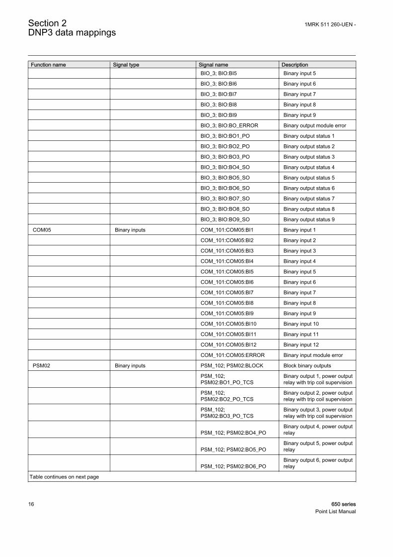
Function name Signal type Signal name Description BIO_3; BIO:BI5 Binary input 5
BIO_3; BIO:BI6 Binary input 6
BIO_3; BIO:BI7 Binary input 7
BIO_3; BIO:BI8 Binary input 8
BIO_3; BIO:BI9 Binary input 9
BIO_3; BIO:BO_ERROR Binary output module error
BIO_3; BIO:BO1_PO Binary output status 1
BIO_3; BIO:BO2_PO Binary output status 2
BIO_3; BIO:BO3_PO Binary output status 3
BIO_3; BIO:BO4_SO Binary output status 4
BIO_3; BIO:BO5_SO Binary output status 5
BIO_3; BIO:BO6_SO Binary output status 6
BIO_3; BIO:BO7_SO Binary output status 7
BIO_3; BIO:BO8_SO Binary output status 8
BIO_3; BIO:BO9_SO Binary output status 9
COM05 Binary inputs COM_101:COM05:BI1 Binary input 1
COM_101:COM05:BI2 Binary input 2
COM_101:COM05:BI3 Binary input 3
COM_101:COM05:BI4 Binary input 4
COM_101:COM05:BI5 Binary input 5
COM_101:COM05:BI6 Binary input 6
COM_101:COM05:BI7 Binary input 7
COM_101:COM05:BI8 Binary input 8
COM_101:COM05:BI9 Binary input 9
COM_101:COM05:BI10 Binary input 10
COM_101:COM05:BI11 Binary input 11
COM_101:COM05:BI12 Binary input 12
COM_101:COM05:ERROR Binary input module error
PSM02 Binary inputs PSM_102; PSM02:BLOCK Block binary outputs
PSM_102;PSM02:BO1_PO_TCS
Binary output 1, power outputrelay with trip coil supervision
PSM_102;PSM02:BO2_PO_TCS
Binary output 2, power outputrelay with trip coil supervision
PSM_102;PSM02:BO3_PO_TCS
Binary output 3, power outputrelay with trip coil supervision
PSM_102; PSM02:BO4_POBinary output 4, power outputrelay
PSM_102; PSM02:BO5_POBinary output 5, power outputrelay
PSM_102; PSM02:BO6_POBinary output 6, power outputrelay
Table continues on next page
Section 2 1MRK 511 260-UEN -DNP3 data mappings
16 650 seriesPoint List Manual

Function name Signal type Signal name Description
PSM_102; PSM02:BO7_SOBinary output 7, signal outputrelay
PSM_102; PSM02:BO8_SOBinary output 8, signal outputrelay
PSM_102; PSM02:BO9_SOBinary output 9, signal outputrelay
PSM03 Binary inputs PSM_102; PSM03BLOCK Block binary outputs
PSM_102;PSM03:BO1_PO_TCS
Binary output 1, power outputrelay with trip coil supervision
PSM_102;PSM03:BO2_PO_TCS
Binary output 2, power outputrelay with trip coil supervision
PSM_102;PSM03:BO3_PO_TCS
Binary output 3, power outputrelay with trip coil supervision
PSM_102; PSM03:BO4_POBinary output 4, power outputrelay
PSM_102; PSM03:BO5_POBinary output 5, power outputrelay
PSM_102; PSM03:BO6_POBinary output 6, power outputrelay
PSM_102; PSM03:BO7_SOBinary output 7, signal outputrelay
PSM_102; PSM03:BO8_SOBinary output 8, signal outputrelay
PSM_102; PSM03:BO9_SOBinary output 9, signal outputrelay
General command handling from DNP master
"In CMT, the 1st binarycommand signal of instance 1is shown as 'AUTOBITS:1.CMDBIT1' The signals canbe connected to any binaryinput signal of any function"
AUTOBITS Binary outputs AUTOBITS:CMDBIT1 Command out bit 1
AUTOBITS:CMDBIT2 Command out bit 2
AUTOBITS:CMDBIT3 Command out bit 3
AUTOBITS:CMDBIT4 Command out bit 4
AUTOBITS:CMDBIT5 Command out bit 5
AUTOBITS:CMDBIT6 Command out bit 6
AUTOBITS:CMDBIT7 Command out bit 7
AUTOBITS:CMDBIT8 Command out bit 8
AUTOBITS:CMDBIT9 Command out bit 9
AUTOBITS:CMDBIT10 Command out bit 10
AUTOBITS:CMDBIT11 Command out bit 11
AUTOBITS:CMDBIT12 Command out bit 12
AUTOBITS:CMDBIT13 Command out bit 13
AUTOBITS:CMDBIT14 Command out bit 14
AUTOBITS:CMDBIT15 Command out bit 15
Table continues on next page
1MRK 511 260-UEN - Section 2DNP3 data mappings
650 series 17Point List Manual

Function name Signal type Signal name Description AUTOBITS:CMDBIT16 Command out bit 16
AUTOBITS:CMDBIT17 Command out bit 17
AUTOBITS:CMDBIT18 Command out bit 18
AUTOBITS:CMDBIT19 Command out bit 19
AUTOBITS:CMDBIT20 Command out bit 20
AUTOBITS:CMDBIT21 Command out bit 21
AUTOBITS:CMDBIT22 Command out bit 22
AUTOBITS:CMDBIT23 Command out bit 23
AUTOBITS:CMDBIT24 Command out bit 24
AUTOBITS:CMDBIT25 Command out bit 25
AUTOBITS:CMDBIT26 Command out bit 26
AUTOBITS:CMDBIT27 Command out bit 27
AUTOBITS:CMDBIT28 Command out bit 28
AUTOBITS:CMDBIT29 Command out bit 29
AUTOBITS:CMDBIT30 Command out bit 30
AUTOBITS:CMDBIT31 Command out bit 31
AUTOBITS:CMDBIT32 Command out bit 32
General functions for showing signals for DNP master
"In CMT the analog signal ofinstance 1 of MVGGIO isshown as 'MVGGIO:1.VALUE' The signals can beconnected to any binaryrespectively analog outputsignal of any function"
MVGGIO Analog inputs MVGGIO:VALUE Magnitude of deadband value
SP16GGIO Binary inputs SP16GGIO:OUT1 Output 1 status
SP16GGIO:OUT2 Output 2 status
SP16GGIO:OUT3 Output 3 status
SP16GGIO:OUT4 Output 4 status
SP16GGIO:OUT5 Output 5 status
SP16GGIO:OUT6 Output 6 status
SP16GGIO:OUT7 Output 7 status
SP16GGIO:OUT8 Output 8 status
SP16GGIO:OUT9 Output 9 status
SP16GGIO:OUT10 Output 10 status
SP16GGIO:OUT11 Output 11 status
SP16GGIO:OUT12 Output 12 status
SP16GGIO:OUT13 Output 13 status
SP16GGIO:OUT14 Output 14 status
SP16GGIO:OUT15 Output 15 status
SP16GGIO:OUT16 Output 16 status
Table continues on next page
Section 2 1MRK 511 260-UEN -DNP3 data mappings
18 650 seriesPoint List Manual

Function name Signal type Signal name Description
SP16GGIO:OUTOROutput status logic OR gatefor input 1 to 16
SPGGIO Binary inputs SPGGIO:OUT Output status
Directly linked signalsIn CMT the analog signal ofinstance 1 of B16I is shownas "B16I: 1.OUT"
AEGGAPC Binary inputs AEGGAPC:TRIPTrip signal from accidentalenergizing protection
B16I Analog inputs B16I:OUT Output value
B16IFCVI Analog inputs B16IFCVI:OUT Output value
BRCPTOC Binary inputs BRCPTOC:TRIPOperate signal of theprotection logic
CCRBRF Binary inputs CCRBRF:TRBUBackup trip by breaker failureprotection function
CCRBRF:TRRETRetrip by breaker failureprotection function
CCRPLD Binary inputs CCRPLD:TRIP Trip signal to CB
CCSRDIF Binary inputs CCSRDIF:FAILDetection of current circuitfailure
CMMXU Analog inputs CMMXU:IL1 IL1 Amplitude
CMMXU:IL1ANGL IL1 Angle
CMMXU:IL2 IL2 Amplitude
CMMXU:IL2ANGL IL2 Angle
CMMXU:IL3 IIL3 Amplitude
CMMXU:IL3ANGL IL3 Angle
CMSQI Analog inputs CMSQI:3I0 3I0 Amplitude
CMSQI:3I0ANGL 3I0 Angle
CMSQI:I1 I1 Amplitude
CMSQI:I1ANGL I1 Angle
CMSQI:I2 I2 Amplitude
CMSQI:I2ANGL I2Angle
CNTGGIO Counters CNTGGIO:VALUE1 Output of counter 1
CNTGGIO:VALUE2 Output of counter 2
CNTGGIO:VALUE3 Output of counter 3
CNTGGIO:VALUE4 Output of counter 4
CNTGGIO:VALUE5 Output of counter 5
CNTGGIO:VALUE6 Output of counter 6
CSPRBRF Binary inputs CSPRBRF:TRBU Back-up trip
CSPRBRF:TRRET Retrip
CVMMXN Analog inputs CVMMXN:FSystem frequency magnitudeof deadband value
CVMMXN:ICalculated current magnitudeof deadband value
Table continues on next page
1MRK 511 260-UEN - Section 2DNP3 data mappings
650 series 19Point List Manual

Function name Signal type Signal name Description
CVMMXN:PActive power magnitude ofdeadband value
CVMMXN:PFPower factor magnitude ofdeadband value
CVMMXN:QReactive power magnitude ofdeadband value
CVMMXN:SApparent power magnitude ofdeadband value
CVMMXN:UCalculated voltage magnitudeof deadband value
Binary inputs CVMMXN:ILAG Current is lagging voltage
CVMMXN:ILEAD Current is leading voltage
DNPFREC Analog inputs DNPFREC:ActSetGrp Active setting group
DNPFREC:Ch1Ang Prefault Angle
DNPFREC:Ch1FltAng Fault Angle
DNPFREC:Ch1FltMag Fault Magnitude
DNPFREC:Ch1Mag Prefault Magnitude
DNPFREC:Ch2Ang Prefault Angle
DNPFREC:Ch2FltAng Fault Angle
DNPFREC:Ch2FltMag Fault Magnitude
DNPFREC:Ch2Mag Prefault Magnitude
DNPFREC:Ch3Ang Prefault Angle
DNPFREC:Ch3FltAng Fault Angle
DNPFREC:Ch3FltMag Fault Magnitude
DNPFREC:Ch3Mag Prefault Magnitude
DNPFREC:Ch4Ang Prefault Angle
DNPFREC:Ch4FltAng Fault Angle
DNPFREC:Ch4FltMag Fault Magnitude
DNPFREC:Ch4Mag Prefault Magnitude
DNPFREC:Ch5Ang Prefault Angle
DNPFREC:Ch5FltAng Fault Angle
DNPFREC:Ch5FltMag Fault Magnitude
DNPFREC:Ch5Mag Prefault Magnitude
DNPFREC:Ch6Ang Prefault Angle
DNPFREC:Ch6FltAng Fault Angle
DNPFREC:Ch6FltMag Fault Magnitude
DNPFREC:Ch6Mag Prefault Magnitude
DNPFREC:Ch7Ang Prefault Angle
DNPFREC:Ch7FltAng Fault Angle
DNPFREC:Ch7FltMag Fault Magnitude
DNPFREC:Ch7Mag Prefault Magnitude
Table continues on next page
Section 2 1MRK 511 260-UEN -DNP3 data mappings
20 650 seriesPoint List Manual

Function name Signal type Signal name Description DNPFREC:Ch8Ang Prefault Angle
DNPFREC:Ch8FltAng Fault Angle
DNPFREC:Ch8FltMag Fault Magnitude
DNPFREC:Ch8Mag Prefault Magnitude
DNPFREC:Ch9Ang Prefault Angle
DNPFREC:Ch9FltAng Fault Angle
DNPFREC:Ch9FltMag Fault Magnitude
DNPFREC:Ch9Mag Prefault Magnitude
DNPFREC:Ch10Ang Prefault Angle
DNPFREC:Ch10FltAng Fault Angle
DNPFREC:Ch10FltMag Fault Magnitude
DNPFREC:Ch10Mag Prefault Magnitude
DNPFREC:Ch11Ang Prefault Angle
DNPFREC:Ch11FltAng Fault Angle
DNPFREC:Ch11FltMag Fault Magnitude
DNPFREC:Ch11Mag Prefault Magnitude
DNPFREC:Ch12Ang Prefault Angle
DNPFREC:Ch12FltAng Fault Angle
DNPFREC:Ch12FltMag Fault Magnitude
DNPFREC:Ch12Mag Prefault Magnitude
DNPFREC:Ch13Ang Prefault Angle
DNPFREC:Ch13FltAng Fault Angle
DNPFREC:Ch13FltMag Fault Magnitude
DNPFREC:Ch13Mag Prefault Magnitude
DNPFREC:Ch14Ang Prefault Angle
DNPFREC:Ch14FltAng Fault Angle
DNPFREC:Ch14FltMag Fault Magnitude
DNPFREC:Ch14Mag Prefault Magnitude
DNPFREC:Ch15Ang Prefault Angle
DNPFREC:Ch15FltAng Fault Angle
DNPFREC:Ch15FltMag Fault Magnitude
DNPFREC:Ch15Mag Prefault Magnitude
DNPFREC:Ch16Ang Prefault Angle
DNPFREC:Ch16FltAng Fault Angle
DNPFREC:Ch16FltMag Fault Magnitude
DNPFREC:Ch16Mag Prefault Magnitude
DNPFREC:Ch17Ang Prefault Angle
DNPFREC:Ch17FltAng Fault Angle
DNPFREC:Ch17FltMag Fault Magnitude
Table continues on next page
1MRK 511 260-UEN - Section 2DNP3 data mappings
650 series 21Point List Manual

Function name Signal type Signal name Description DNPFREC:Ch17Mag Prefault Magnitude
DNPFREC:Ch18Ang Prefault Angle
DNPFREC:Ch18FltAng Fault Angle
DNPFREC:Ch18FltMag Fault Magnitude
DNPFREC:Ch18Mag Prefault Magnitude
DNPFREC:Ch19Ang Prefault Angle
DNPFREC:Ch19FltAng Fault Angle
DNPFREC:Ch19FltMag Fault Magnitude
DNPFREC:Ch19Mag Prefault Magnitude
DNPFREC:Ch20Ang Prefault Angle
DNPFREC:Ch20FltAng Fault Angle
DNPFREC:Ch20FltMag Fault Magnitude
DNPFREC:Ch20Mag Prefault Magnitude
DNPFREC:Ch21Ang Prefault Angle
DNPFREC:Ch21FltAng Fault Angle
DNPFREC:Ch21FltMag Fault Magnitude
DNPFREC:Ch21Mag Prefault Magnitude
DNPFREC:Ch22Ang Prefault Angle
DNPFREC:Ch22FltAng Fault Angle
DNPFREC:Ch22FltMag Fault Magnitude
DNPFREC:Ch22Mag Prefault Magnitude
DNPFREC:Ch23Ang Prefault Angle
DNPFREC:Ch23FltAng Fault Angle
DNPFREC:Ch23FltMag Fault Magnitude
DNPFREC:Ch23Mag Prefault Magnitude
DNPFREC:Ch24Ang Prefault Angle
DNPFREC:Ch24FltAng Fault Angle
DNPFREC:Ch24FltMag Fault Magnitude
DNPFREC:Ch24Mag Prefault Magnitude
DNPFREC:Ch25Ang Prefault Angle
DNPFREC:Ch25FltAng Fault Angle
DNPFREC:Ch25FltMag Fault Magnitude
DNPFREC:Ch25Mag Prefault Magnitude
DNPFREC:Ch26Ang Prefault Angle
DNPFREC:Ch26FltAng Fault Angle
DNPFREC:Ch26FltMag Fault Magnitude
DNPFREC:Ch26Mag Prefault Magnitude
DNPFREC:Ch27Ang Prefault Angle
DNPFREC:Ch27FltAng Fault Angle
Table continues on next page
Section 2 1MRK 511 260-UEN -DNP3 data mappings
22 650 seriesPoint List Manual

Function name Signal type Signal name Description DNPFREC:Ch27FltMag Fault Magnitude
DNPFREC:Ch27Mag Prefault Magnitude
DNPFREC:Ch28Ang Prefault Angle
DNPFREC:Ch28FltAng Fault Angle
DNPFREC:Ch28FltMag Fault Magnitude
DNPFREC:Ch28Mag Prefault Magnitude
DNPFREC:Ch29Ang Prefault Angle
DNPFREC:Ch29FltAng Fault Angle
DNPFREC:Ch29FltMag Fault Magnitude
DNPFREC:Ch29Mag Prefault Magnitude
DNPFREC:Ch30Ang Prefault Angle
DNPFREC:Ch30FltAng Fault Angle
DNPFREC:Ch30FltMag Fault Magnitude
DNPFREC:Ch30Mag Prefault Magnitude
DNPFREC:Ch31TrigMag Magnitude at trigger
DNPFREC:Ch32TrigMag Magnitude at trigger
DNPFREC:Ch33TrigMag Magnitude at trigger
DNPFREC:Ch34TrigMag Magnitude at trigger
DNPFREC:Ch35TrigMag Magnitude at trigger
DNPFREC:Ch36TrigMag Magnitude at trigger
DNPFREC:Ch37TrigMag Magnitude at trigger
DNPFREC:Ch38TrigMag Magnitude at trigger
DNPFREC:Ch39TrigMag Magnitude at trigger
DNPFREC:Ch40TrigMag Magnitude at trigger
DNPFREC:FaultFreq Fault Freq
DNPFREC:FaultLoc Fault Location
DNPFREC:FaultNumber Fault Number
DNPFREC:FaultType Fault Type
DNPFREC:NoOfFaultIED No. of faults in IED
DNPFREC:TrigDay Trigger Day
DNPFREC:TrigHour Trigger Hour
DNPFREC:TrigMillisec Trigger Millisecond
DNPFREC:TrigMin Trigger Minute
DNPFREC:TrigMonth Trigger Month
DNPFREC:TrigSec Trigger Second
DNPFREC:TrigSigIdChannel number for triggersignal
DNPFREC:TrigYear Trigger year
Binary outputs DNPFREC:GetFirstRec Get first disturbance
DNPFREC:GetNextRec Get next disturbance
Table continues on next page
1MRK 511 260-UEN - Section 2DNP3 data mappings
650 series 23Point List Manual

Function name Signal type Signal name Description DNPFREC:GetPrevRec Get previous disturbance
DNSPTOC Binary inputs DNSPTOC:TRIP General trip signal
DNSPTOC:TROC1 Trip signal from step 1 (OC1)
DNSPTOC:TROC2 Trip signal from step 2 (OC2)
DRPRDRE Analog inputs DRPRDRE:FaultNumber Disturbance fault number
Binary inputs DRPRDRE:RECMADE Disturbance recording made
ECPSCH Binary inputs ECPSCH:CS
Carrier sending byCommunication SchemeLogic
ECPSCH:LCG Loss of carrier guard signal
ECPSCH:PRORXTeleprotection signal receivedfor a forward fault
ECPSCH:TRIPTrip by CommunicationScheme Logic
ECRWPSCH Binary inputs ECRWPSCH:CRPOR Carrier signal receivedfrom remote end
ECRWPSCH:ECHO Carrier send by WEI logic
ECRWPSCH:TRWEI Trip of WEI logic
EF4PTOC Binary inputs EF4PTOC:STFWForward directional startsignal
EF4PTOC:STRVReverse directional startsignal
EF4PTOC:TRIP General trip signal
EF4PTOC:TR1 Trip signal from step 1
EF4PTOC:TR2 Trip signal from step 2
EF4PTOC:TR3 Trip signal from step 3
EF4PTOC:TR4 Trip signal from step 4
EFPIOC Binary inputs EFPIOC:TRIP Trip signal
ETPMMTR Binary inputs ETPMMTR:EAFALM
Alarm for active forwardenergy exceeding limit in setinterval
ETPMMTR:EARALM
Alarm for active reverseenergy exceeding limit in setinterval
ETPMMTR:ERFALM
Alarm for reactive forwardenergy exceeding limit in setinterval
ETPMMTR:ERRALM
Alarm for reactive reverseenergy exceeding limit in setinterval
FDPSPDIS Binary inputs FDPSPDIS:STFWL1Fault detected in phase L1-forward direction
FDPSPDIS:STFWL2Fault detected in phase L2-forward direction
FDPSPDIS:STFWL3Fault detected in phase L3-forward direction
Table continues on next page
Section 2 1MRK 511 260-UEN -DNP3 data mappings
24 650 seriesPoint List Manual

Function name Signal type Signal name Description
FDPSPDIS:STFWPEEarth fault detected inforward direction
FDPSPDIS:STNDL1Non-directional start detectedin L1
FDPSPDIS:STNDL2Non-directional start detectedin L2
FDPSPDIS:STNDL3Non-directional start detectedin L3
FDPSPDIS:STNDPENon-directional start, Phase-Earth
FDPSPDIS:STRVL1Fault detected in phase L1-reverse direction
FDPSPDIS:STRVL2Fault detected in phase L2-reverse direction
FDPSPDIS:STRVL3Fault detected in phase L3-reverse direction
FDPSPDIS:STRVPEEarth fault detected inreverse direction
FDPSPDIS:TRIP Trip output
FMPSPDIS Binary inputs FMPSPDIS:START General start signal
FMPSPDIS:STL1 Fault detected in phase L1
FMPSPDIS:STL2 Fault detected in phase L2
FMPSPDIS:STL3 Fault detected in phase L3
FMPSPDIS:STPE Earth fault detected
GENPDIF Binary Inputs GENPDIF:BLKHCommon harmonic blocksignal
GENPDIF:INTDISTIndication that internal faulthas been detected
GENPDIF:OPENCTALOpen CT Alarm output signal.Issued after a delay
GENPDIF:TRIP General, common trip signal
GENPDIF:TRIPRESTrip signal from restraineddifferential protection
GENPDIF:TRIPUNRETrip signal from unrestraineddifferential protection
GENPDIF:TRNSSENSTrip signal from sensitive neg.seq. diff. protection
GENPDIF:TRNSUNRTrip signal from unrestr. neg.seq. diff. protection
GOPPDOP Binary inputs GOPPDOP:TRIP General trip signal
GOPPDOP:TRIP1 Trip signal from stage 1
GOPPDOP:TRIP2 Trip signal from stage 2
GUPPDUP Binary inputs GUPPDUP:TRIP General trip signal
GUPPDUP:TRIP1 Trip signal from stage 1
GUPPDUP:TRIP2 Trip signal from stage 2
HZPDIF Binary inputs HZPDIF:TRIP Trip signal
Table continues on next page
1MRK 511 260-UEN - Section 2DNP3 data mappings
650 series 25Point List Manual

Function name Signal type Signal name DescriptionINTERRSIG Analog inputs INTERRSIG:TSYNCERR Time synchronization error
Binary inputs INTERRSIG:FAIL Internal fail
INTERRSIG:WARNING Internal warning
LEPDIS Binary inputs LEPDIS:START General start signal
LEPDIS:STL1 Fault detected in phase L1
LEPDIS:STL2 Fault detected in phase L2
LEPDIS:STL3 Fault detected in phase L3
LEXPDIS Binary inputs LEXPDIS:TRIP Common trip signal
LEXPDIS:TRZ1Trip signal from impedancezone Z1
LEXPDIS:TRZ2Trip signal from impedancezone Z2
LMBRFLO Binary inputs LMBRFLO:FltDistLngUnitDistance to fault in line lengthunit
LOVPTUV Binary inputs LOVPTUV:TRIP Trip signal
LCPTTR Binary inputs LCPTTR:ALARM Alarm signal
LCPTTR:LOCKOUT Lockout signal
LCPTTR:TRIP General trip signal
LFPTTR Binary inputs LFPTTR:ALARM Alarm signal
LFPTTR:LOCKOUT Lockout signal
LFPTTR:TRIP General trip signal
NS2PTOC Binary inputs NS2PTOC:ALARM Alarm signal
NS2PTOC:TR1 Trip signal for step 1
NS2PTOC:TR2 Trip signal for step 2
NS2PTOC:TRIP Common trip signal
OC4PTOC Binary inputs OC4PTOC:TR1 Trip signal from step 1
OC4PTOC:TR2 Trip signal from step 2
OC4PTOC:TR3 Trip signal from step 3
OC4PTOC:TR4 Trip signal from step 4
OC4PTOC:TRIP General trip signal
OC4SPTOC Binary inputs OC4SPTOC:TR1 Trip signal from step 1
OC4SPTOC:TR2 Trip signal from step 2
OC4SPTOC:TR3 Trip signal from step 3
OC4SPTOC:TR4 Trip signal from step 4
OC4SPTOC:TRIP General trip signal
OC4SPTOC:TRL1 Trip signal from phase L1
OC4SPTOC:TRL2 Trip signal from phase L2
OC4SPTOC:TRL3 Trip signal from phase L3
OEXPVPH Analog inputs OEXPVPH:VPERHZVoltage-to-frequency ratio inper-unit
Binary inputs OEXPVPH:.ALARM Overexcitation alarm signal
Table continues on next page
Section 2 1MRK 511 260-UEN -DNP3 data mappings
26 650 seriesPoint List Manual

Function name Signal type Signal name Description OEXPVPH:TRIP General trip signal
OOSPPAM Binary inputs OOSPPAM:TRIP
Common trip, issued wheneither zone 1 or zone 2 givetrip
OV2PTOV Binary inputs OV2PTOV:TR1 Trip signal from step 1
OV2PTOV:TR2 Trip signal from step 2
OV2PTOV:TRIP General trip signal
PHPIOC Binary inputs PHPIOC:TRIP General trip signal
QCBAY Binary inputs QCBAY:CMD_BLKDFunction is blocked forcommands
QCBAY:LOC Local operation allowed
QCBAY:REM Remote operation allowed
QCBAY:UPD_BLKD Update of position is blocked
REFPDIF Binary inputs REFPDIF:BLK2H Block due to 2nd harmonic
REFPDIF:DIROKDirectional criteria haveoperated for internal fault
REFPDIF:TRIP General trip signal
ROV2PTOV Binary inputs ROV2PTOV:TR1 Trip signal from step 1
ROV2PTOV:TR2 Trip signal from step 2
ROV2PTOV:TRIP General trip signal
SAPFRC Binary inputs SAPFRC:BLKDMAGNBlocking indication due to lowamplitude
SAPFRC:TRIPOperating/trip signal forfrequency gradient
SAPTOF Binary inputs SAPTOF:BLKDMAGNMeasurement blocked due tolow amplitude
SAPTOF:TRIP General trip signal
SAPTUF Binary inputs SAPTUF:BLKDMAGNMeasurement blocked due tolow voltage amplitude
SAPTUF:TRIP General trip signal
SCILO Binary inputs SCILO:EN_CLOSE
Close operation at open orintermediate or bad positionis enabled
SCILO:EN_OPEN
Open operation at closed orintermediate or bad positionis enabled
SCSWI Analog inputs SCSWI:L_CAUSELatest value of the errorindication during command
Binary inputs SCSWI:CMD_BLK Commands are blocked
Binary outputs SCSWI:CLOSE_CMDClose command parameterfor DNP protocol
SCSWI:OPEN_CMDOpen command parameterfor DNP protocol
Double bit indications SCSWI:POSITION Position indication
SDDRFUF Binary inputs SDDRFUF:BLKU General start of function
Table continues on next page
1MRK 511 260-UEN - Section 2DNP3 data mappings
650 series 27Point List Manual

Function name Signal type Signal name Description
SDEPSDE Binary inputs SDEPSDE:TRDIRINTrip of the directional residualovercurrent
SDEPSDE:TRIP General trip signal
SDEPSDE:TRNDINTrip of non-directionalresidual overcurrent
SDEPSDE:TRUNTrip of non-directionalresidual overvoltage
SESRSYN Analog inputs SESRSYN:FRDIFFMECalculated difference infrequency
SESRSYN:PHDIFFMECalculated difference ofphase angle
SESRSYN:UDIFFMECalculated difference involtage
Binary inputs SESRSYN:AUTOENOKAutomatic energizing checkOK
SESRSYN:AUTOREL Automatic release
SESRSYN:B1SEL Bus1 selected
SESRSYN:B2SEL Bus2 selected
SESRSYN:LN2SEL Line2 selected
SESRSYN:LNSEL Line selected
SESRSYN:MANENOK Manual energizing check OK
SESRSYN:MANREL Manual release
SESRSYN:SYNFAIL Synchronizing failed
SESRSYN:SYNOK Synchronizing OK output
SESRSYN:SYNPROGR Synchronizing in progress
SLGGIO Analog inputs SLGGIO:SWPOSNSwitch position as integervalue
SMBRREC Binary inputs SMBRREC:3PT1Three-phase reclosing inprogress, shot 1
SMBRREC:3PT2Three-phase reclosing inprogress, shot 2
SMBRREC:3PT3Three-phase reclosing inprogress, shot 3
SMBRREC:3PT4Three-phase reclosing inprogress, shot 4
SMBRREC:3PT5Three-phase reclosing inprogress, shot 5
SMBRREC:ACTIVEReclosing sequence inprogress
SMBRREC:BLOCKED AR is in blocked state
SMBRREC:CLOSECB Closing command for CB
SMBRREC:READYIndicates that AR is ready fora new sequence
SMBRREC:SETON AR operation is switched on
Table continues on next page
Section 2 1MRK 511 260-UEN -DNP3 data mappings
28 650 seriesPoint List Manual

Function name Signal type Signal name Description
SMBRREC:UNSUCCL
Reclosing unsuccessful,signal resets after the reclaimtime
Counters SMBRREC:COUNT3P1Counting the number of three-phase reclosing shot 1
SMBRREC:COUNT3P2Counting the number of three-phase reclosing shot 2
SMBRREC:COUNT3P3Counting the number of three-phase reclosing shot 3
SMBRREC:COUNT3P4Counting the number of three-phase reclosing shot 4
SMBRREC:COUNT3P5Counting the number of three-phase reclosing shot 5
SMPPTRC Binary inputs SMPPTRC:CLLKOUTCircuit breaker lockout output(set until reset)
SMPPTRC:TRIP General trip signal
SPTPIOC Binary inputs SPTPIOC:TRIP General trip signal
SPTPIOC:TRL1 Trip signal from phase L1
SPTPIOC:TRL2 Trip signal from phase L2
SPTPIOC:TRL3 Trip signal from phase L3
SPTPTRC Binary inputs SPTPTRC:CLLKOUTCircuit breaker lockout output(set until reset)
SPTPTRC:TR1P Tripping single-pole
SPTPTRC:TR3P Tripping three-pole
SPTPTRC:TRIP General trip signal
SPTPTRC:TRL1 Trip signal from phase L1
SPTPTRC:TRL2 Trip signal from phase L2
SPTPTRC:TRL3 Trip signal from phase L3
SPVNZBAT Binary inputs SPVNZBAT:ST_UHIStart signal when batteryvoltage exceeds upper limit
SPVNZBAT:ST_ULOWStart signal when batteryvoltage drops below lower limit
SSCBR Binary inputs SSCBR:CBLIFEALRemaining life of CBexceeded alarm limit
SSCBR:NO_OPR Number of CB operation cycle
SSCBR:PRESALM Pressure below alarm level
SSCBR:PRESLO Pressure below lockout level
SSCBR:SPRCHRALSpring charging time hascrossed the set value
SSIMG Binary inputs SSIMG:PRES_ALM Pressure below alarm level
SSIMG:PRES_LO Pressure below lockout level
SSIMG:TEMP_ALMTemperature above alarmlevel
SSIMG:TEMP_LOTemperature above lockoutlevel
Table continues on next page
1MRK 511 260-UEN - Section 2DNP3 data mappings
650 series 29Point List Manual

Function name Signal type Signal name DescriptionSSIML Binary inputs SSIML:LVL_ALM Level below alarm level
SSIML:LVL_LO Level below lockout level
SSIML:TEMP_ALMTemperature above alarmlevel
SSIML:TEMP_LOTemperature above lockoutlevel
STBPTOC Binary inputs STBPTOC:TRIP General trip signal
STBRREC Counters STBRREC:1PT1Single-phase reclosing inprogress, shot 1
STBRREC:3PT1Three-phase reclosing inprogress, shot 1
STBRREC:3PT2Three-phase reclosing inprogress, shot 2
STBRREC:3PT3Three-phase reclosing inprogress, shot 3
STBRREC:3PT4Three-phase reclosing inprogress, shot 4
STBRREC:3PT5Three-phase reclosing inprogress, shot 5
STBRREC:ACTIVEReclosing sequence inprogress
STBRREC:BLOCKED AR is in blocked state
STBRREC:CLOSECB Closing command for CB
STBRREC:READYIndicates that AR is ready fora new sequence
STBRREC:SETON AR operation is switched on
STBRREC:UNSUCCL
Reclosing unsuccessful,signal resets after the reclaimtime
Binary outputs STBRREC:COUNT1PCounting the number of single-phase reclosing shots
STBRREC:COUNT3P1Counting the number of three-phase reclosing shot 1
STBRREC:COUNT3P2Counting the number of three-phase reclosing shot 2
STBRREC:COUNT3P3Counting the number of three-phase reclosing shot 3
STBRREC:COUNT3P4Counting the number of three-phase reclosing shot 4
STBRREC:COUNT3P5Counting the number of three-phase reclosing shot 5
STEFPHIZ Binary inputs STEFPHIZ:TRIP Main, common trip command
STEFPHIZ:TRIP3HTrip by one of two 3rdharmonic voltage-based prot.
STEFPHIZ:TRIPUNTrip by fund. freq. neutral over-voltage protection
SXCBR Binary inputs SXCBR:CLOSEPOS Apparatus closed position
Table continues on next page
Section 2 1MRK 511 260-UEN -DNP3 data mappings
30 650 seriesPoint List Manual

Function name Signal type Signal name Description SXCBR:OPENPOS Apparatus open position
SXCBR:UPD_BLKDUpdate of position indicationis blocked
Counters SXCBR:CNT_VAL Operation counter value
Double bit indications SXCBR:POSITION Apparatus position indication
SXCBR:TR_POS Truck position indication
SXSWI Binary inputs SXSWI:CLOSEPOS Apparatus closed position
SXSWI:OPENPOS Apparatus open position
SXSWI:UPD_BLKDUpdate of position indicationis blocked
Counters SXSWI:CNT_VAL Operation counter value
Double bit indications SXSWI:POSITION Apparatus position indication
T2WPDIF Binary inputs T2WPDIF:BLK2HGeneral second harmonicblock signal
T2WPDIF:BLK5HGeneral fifth harmonic blocksignal
T2WPDIF:INTFAULTIndication that internal faulthas been detected
T2WPDIF:TRIP General trip signal
T2WPDIF:TRIPRESTrip signal from restraineddifferential protection
T2WPDIF:TRIPUNRETrip signal from unrestraineddifferential protection
T2WPDIF:TRNSSENS
Trip signal from sensitivenegative sequence differentialprotection
T2WPDIF:TRNSUNR
Trip signal from unrestrainednegative-sequencedifferential protection
T3WPDIF Binary inputs T3WPDIF:BLK2HGeneral second harmonicblock signal
T3WPDIF:BLK5HGeneral fifth harmonic blocksignal
T3WPDIF:INTFAULTIndication that internal faulthas been detected
T3WPDIF:TRIP General trip signal
T3WPDIF:TRIPRESTrip signal from restraineddifferential protection
T3WPDIF:TRIPUNRETrip signal from unrestraineddifferential protection
T3WPDIF:TRNSSENS
Trip signal from sensitivenegative sequence differentialprotection
T3WPDIF:TRNSUNR
Trip signal from unrestrainednegative sequence differentialprotection
TCMYLTC Analog inputs TCMYLTC:TCPOSInteger value correspondingto actual tap position
Table continues on next page
1MRK 511 260-UEN - Section 2DNP3 data mappings
650 series 31Point List Manual

Function name Signal type Signal name Description
Binary inputs TCMYLTC:CNT_VALNumber of operations on tapchanger
TCMYLTC:HIPOSALAlarm for tap in the highestvolt position
TCMYLTC:LOPOSALAlarm for tap in the lowestvolt position
TCMYLTC:POSERRAL
Alarm that indicates aproblem with the positionindication
TMAGGIO Binary inputs TMAGGIO:OUTPUT1OR function betweeen inputs1 to 16
TMAGGIO:OUTPUT2OR function between inputs17 to 32
TMAGGIO:OUTPUT3OR function between inputs 1to 32
TR8ATCC Analog inputs TR8ATCC:BUSVOLTAverage of measured busbarvoltage (service value)
TR8ATCC:ICIRCUL Circulating current
TR8ATCC:ILOADMagnitude of measured loadcurrent (service value)
TR8ATCC:TCPOS Tap position
TR8ATCC:ULOADCalculated compensatedvoltage (service value)
Binary inputs TR8ATCC:AUTOAutomatic control mode isactive
TR8ATCC:AUTOBLKBlock of auto-commandscommands
TR8ATCC:COMMERR Communication error
TR8ATCC:DISCONN Transformer is disconnected
TR8ATCC:FOLLOWER This transformer is follower
TR8ATCC:MAN Manual control mode is active
TR8ATCC:MASTER Transformer is master
TR8ATCC:MSTRSLV Master slave is active
TR8ATCC:OUTOFPOSDifference in tap positionsexceeded the set limit
TR8ATCC:PARALLELTransformer operates inparallel mode
TR8ATCC:SINGLETransformer operates insingle mode
TR8ATCC:TOTBLKBlock of auto-commands andmanual commands
TRPTTR Binary inputs TRPTTR:ALARM1 First-level alarm signal
TRPTTR:ALARM2 Second-level alarm signal
TRPTTR:TRIP Trip Signal
UC2PTUC Binary inputs UC2PTUC:TR1 Operate signal for step 1
UC2PTUC:TR1L1 Operate signal for step 1 in L1
Table continues on next page
Section 2 1MRK 511 260-UEN -DNP3 data mappings
32 650 seriesPoint List Manual

Function name Signal type Signal name Description UC2PTUC:TR1L2 Operate signal for step 1 in L2
UC2PTUC:TR1L3 Operate signal for step 1 in L3
UC2PTUC:TR2 Operate signal for step 2
UC2PTUC:TR2L1 Operate signal for step 2 in L1
UC2PTUC:TR2L2 Operate signal for step 2 in L2
UC2PTUC:TR2L3 Operate signal for step 2 in L3
UC2PTUC:TRIP General trip signal
UV2PTUV Binary inputs UV2PTUV:TR1 Trip signal from step 1
UV2PTUV:TR2 Trip signal from step 2
UV2PTUV:TRIP General trip signal
VMMXU Analog inputs VMMXU:UL12 UL12 Amplitude
VMMXU:UL12ANGL UL12 Angle
VMMXU:UL23 UL23 Amplitude
VMMXU:UL23ANGL UL23 Angle
VMMXU:UL31 UL31 Amplitude
VMMXU:UL31ANGL UL31 Angle
VMSQI Analog inputs VMSQI:3U0 3U0
VMSQI:3U0ANGL 3U0 Angle
VMSQI:U1 U1 Amplitude
VMSQI:U1ANGL U1 Angle
VMSQI:U2 U2Amplitude
VMSQI:U2ANGL U2Angle
VNMMXU Analog inputs VNMMXU:UL1UL1 Amplitude, magnitude ofreported value
VNMMXU:UL1ANGLUL1 Angle, magnitude ofreported value
VNMMXU:UL2UL2 Amplitude, magnitude ofreported value
VNMMXU:UL2ANGLUL2 Angle, magnitude ofreported value
VNMMXU:UL3UL3 Amplitude, magnitude ofreported value
VNMMXU:UL3ANGLUL3 Angle, magnitude ofreported value
VR2PVOC Binary inputs VR2PVOC:TRIP General trip signal
VR2PVOC:TROCTrip signal from voltagerestraint overcurrent stage
VR2PVOC:TROC2Trip signal from overcurrentfunction OC2
VSGGIO Binary inputs VSGGIO:POS1Position 1 indication, logicalsignal
VSGGIO:POS2Position 2 indication, logicalsignal
Table continues on next page
1MRK 511 260-UEN - Section 2DNP3 data mappings
650 series 33Point List Manual
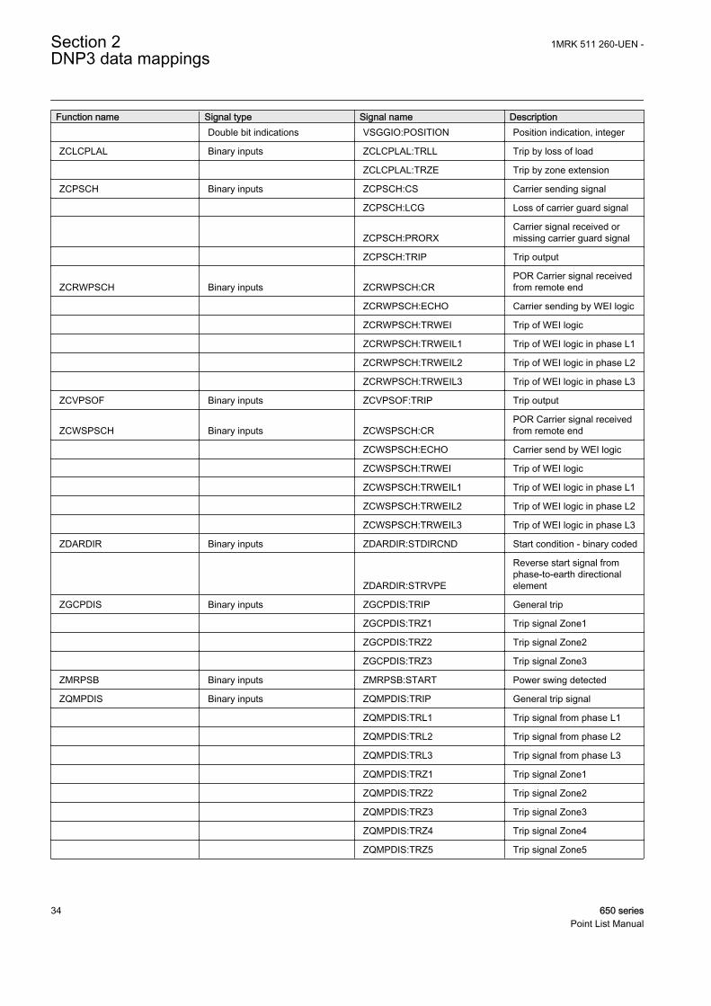
Function name Signal type Signal name Description Double bit indications VSGGIO:POSITION Position indication, integer
ZCLCPLAL Binary inputs ZCLCPLAL:TRLL Trip by loss of load
ZCLCPLAL:TRZE Trip by zone extension
ZCPSCH Binary inputs ZCPSCH:CS Carrier sending signal
ZCPSCH:LCG Loss of carrier guard signal
ZCPSCH:PRORXCarrier signal received ormissing carrier guard signal
ZCPSCH:TRIP Trip output
ZCRWPSCH Binary inputs ZCRWPSCH:CRPOR Carrier signal receivedfrom remote end
ZCRWPSCH:ECHO Carrier sending by WEI logic
ZCRWPSCH:TRWEI Trip of WEI logic
ZCRWPSCH:TRWEIL1 Trip of WEI logic in phase L1
ZCRWPSCH:TRWEIL2 Trip of WEI logic in phase L2
ZCRWPSCH:TRWEIL3 Trip of WEI logic in phase L3
ZCVPSOF Binary inputs ZCVPSOF:TRIP Trip output
ZCWSPSCH Binary inputs ZCWSPSCH:CRPOR Carrier signal receivedfrom remote end
ZCWSPSCH:ECHO Carrier send by WEI logic
ZCWSPSCH:TRWEI Trip of WEI logic
ZCWSPSCH:TRWEIL1 Trip of WEI logic in phase L1
ZCWSPSCH:TRWEIL2 Trip of WEI logic in phase L2
ZCWSPSCH:TRWEIL3 Trip of WEI logic in phase L3
ZDARDIR Binary inputs ZDARDIR:STDIRCND Start condition - binary coded
ZDARDIR:STRVPE
Reverse start signal fromphase-to-earth directionalelement
ZGCPDIS Binary inputs ZGCPDIS:TRIP General trip
ZGCPDIS:TRZ1 Trip signal Zone1
ZGCPDIS:TRZ2 Trip signal Zone2
ZGCPDIS:TRZ3 Trip signal Zone3
ZMRPSB Binary inputs ZMRPSB:START Power swing detected
ZQMPDIS Binary inputs ZQMPDIS:TRIP General trip signal
ZQMPDIS:TRL1 Trip signal from phase L1
ZQMPDIS:TRL2 Trip signal from phase L2
ZQMPDIS:TRL3 Trip signal from phase L3
ZQMPDIS:TRZ1 Trip signal Zone1
ZQMPDIS:TRZ2 Trip signal Zone2
ZQMPDIS:TRZ3 Trip signal Zone3
ZQMPDIS:TRZ4 Trip signal Zone4
ZQMPDIS:TRZ5 Trip signal Zone5
Section 2 1MRK 511 260-UEN -DNP3 data mappings
34 650 seriesPoint List Manual

Section 3 DNP3 protocol implementation
3.1 DNP3 device profile
The following table provides a device profile document in the standard formatdefined in the DNP3 Subset Definitions Document. While it is referred to in theDNP3 Subset Definitions as a document, it is in fact a table, and only a componentof a total interoperability guide. The table, in combination with the Implementationtable and the point list tables, provides a complete configuration/interoperabilityguide for communicating with a device.
When going down in baudrate, the size of the configuration onDNP must be considered.
Table 7: Device profile document
DNP3 device profile documentVendor name: ABB AB
Device name: 650 series IED
Highest DNP level supported: Device function:
For requests: Level + ○ Master
For responses: Level + ● Slave
Notable objects, functions and/or qualifiers supported in addition to the highest DNP levels supported (the complete list is described inthe attached table):For static (non-change event) object requests, request qualifier codes 07 and 08 (limited quantity) and 17 and 28 (index) are supported.Static object requests sent with qualifiers 07 or 08 are responded with qualifiers 00 or 01.16-bit, 32-bit and Floating point analog change events with time may be requested.Floating point analog output status and output block objects 40 and 41 are not supported.Sequential file transfer, object 70, variations 2 through 7, are not supported.Octet string and string event objects 110 and 111 are not supported.Virtual terminal output and event objects 112 and 113 are not supported.Device attribute object 0 is not supported.Data set objects 85-88 are not supported.
Maximum data link frame size (octets): Maximum application fragment size (octets):
Transmitted: 292 Transmitted: Configurable up to 2048(ApLayMaxTxSize for each master session)
Received: 292 Received: Configurable up to 2048(ApLayMaxRxSize for each Master session)
Maximum data link retries: Maximum application layer retries:
● None ● None
○ Fixed ○ Configurable
○ Configurable (0...65535)(DLinkRetries for each channel)
Table continues on next page
1MRK 511 260-UEN - Section 3DNP3 protocol implementation
650 series 35Point List Manual

DNP3 device profile documentRequires data link layer confirmation:
○ Never
○ Always
○ Sometimes
● Configurable as: only when reporting event data(DLinkConfirm for each channel)
Requires application layer confirmation:
○ Never
○ Always
○ When reporting event data (slave devices only)
○ When sending multi-fragment responses (slave devices only)
○ Sometimes
● Configurable as: "Only when reporting event data" or "When reporting event data or multi-fragment messages."(ConfMultiFrag for each master session)
Timeouts while waiting for:
Data linkconfirm:(tDLinkTimeout onDNP3Channelin PST)
● None ○ Fixed at ____ ○ Variable ○ Configurable
Completeappl.fragment:
○ None ○ Fixed at ____ ○ Variable ○ Configurable
Applicationconfirm:(tApplConfTout onDNP3Masterin PST)
○ None ○ Fixed at ____ ○ Variable ● Configurable
Completeappl.response:
● None ○ Fixed at ____ ○ Variable ○ Configurable
Others: • Transmission delay, configurable (tRxToTxMinDel for each channel).• Selecting/Operating arm timeout, configurable (tSelectTimeout for each master session).• Need time interval, configurable (tSynchTimeout for each master session).• Unsolicited notification delay, configurable (tUREvBufTout1, tUREvBufTout2, tUREvBufTout3 for each master
session).• Unsolicited response retry delay, configurable (tURRetryDelay for each master session).• Unsolicited offline iInterval, configurable (tUROfflRtryDel for each master session).
Change events in the IED are generated by the device’s internal event system; they are not polled at a protocol-specificscan rate. The periodicity for each point depends on the point’s data rate in the IED.Binary change event scan period – see aboveDouble bit change event scan period – see aboveAnalog change event scan period – see aboveCounter change event scan period – see above
Sends/Executes Control Operations:
WRITE binaryoutputs
● Never ○ Always ○ Sometimes ○ Configurable
SELECT/OPERATE
○ Never ● Always ○ Sometimes ○ Configurable
Table continues on next page
Section 3 1MRK 511 260-UEN -DNP3 protocol implementation
36 650 seriesPoint List Manual

DNP3 device profile documentDIRECTOPERATE
○ Never ○ Always ○ Sometimes ● Configurable
DIRECTOPERATE -NO ACK
○ Never ○ Always ○ Sometimes ● Configurable
Count > 1 ○ Never ○ Always ● Sometimes ○ Configurable
Pulse on ○ Never ○ Always ● Sometimes ○ Configurable
Pulse off ○ Never ○ Always ● Sometimes ○ Configurable
Latch on ○ Never ○ Always ● Sometimes ○ Configurable
Latch off ○ Never ○ Always ● Sometimes ○ Configurable
Queue ● Never ○ Always ○ Sometimes ○ Configurable
Clear queue ● Never ○ Always ○ Sometimes ○ Configurable
Explanation of "Sometimes" above: Supported binary output control operations depend on the type of point. Please consult the binaryoutput point list description.
Reports binary input change events when no specific variationrequested:
Reports time-tagged binary input change events when no specificvariation requested:
○ Never ○ Never
○ Only when time-tagged ○ Binary input change with time
○ Only non-time-tagged ○ Binary input change with relative time
● Configurable to send one or the other(Obj2DefVar on DNP3Master)
● Configurable (Obj2DefVar on DNP3Master)
Sends unsolicited responses: Sends static data in unsolicited responses:
○ Never ● Never
● Configurable (UREnable onDNP3Master)
○ When device restarts
○ Only certain objects ○ When status flags change
○ Sometimes (attach explanation)
● ENABLE/DISABLE UNSOLICITEDfunction codes supported
No other options are permitted.
Default counter object/variation: Counters roll over at:
○ No counters reported ○ No counters reported
● Configurable (obj20DefVar andobj22DefVar in DNP3Master)
○ Configurable (attach explanation)
○ Default objectDefault variation:
○ 16 bits
○ Point-by-point list attached ● 32 bits
○ Other value: _______
○ Point-by-point list attached
Sends multi-fragment responses:
○ Yes
○ No
Table continues on next page
1MRK 511 260-UEN - Section 3DNP3 protocol implementation
650 series 37Point List Manual

DNP3 device profile document ● Configurable (ApplMultFrgRes on DNP3Master)
Deadbanding is not performed in the DNP protocol stack. Any deadbanding is a property of the IED’s underlying data and is configuredthrough the IED configuration tools.
● = Selected,○ = Not selected
3.2 DNP3 implementation table
The following table identifies which object variations, function codes andqualifiers the IED supports in both request messages and in response messages. Forstatic (non-change event) objects, requests sent with qualifiers 00, 01, 06, 07 or 08are responded with qualifiers 00 or 01. Requests sent with qualifiers 17 or 28 areresponded with qualifiers 17 or 28. For change event objects, qualifiers 17 or 28are always responded.
Table 8: Implementation table
OBJECT REQUEST (Slave will parse) RESPONSE (Slave will respond with)Objectnumber
Variationnumber Description
Function codes(dec) Qualifier codes (hex)
Function codes(dec)
Qualifier codes(hex)
1 0 Binary input – anyvariation
1 (read)22 (assign class)
00, 01 (start-stop)06 (no range, or all)07, 08 (limited qty)17, 27, 28 (index)
1 1(default)
1)
Binary input 1 (read) 00, 01 (start-stop)06 (no range, or all)07, 08 (limited qty)17, 27, 28 (index)
129 (response) 00, 01 (start-stop)17, 28 (index) 2)
1 2 Binary input with status 1 (read) 00, 01 (start-stop)06 (no range, or all)07, 08 (limited qty)17, 27, 28 (index)
129 (response) 00, 01 (start-stop)17, 28 (index)
2 1 Binary input changewithout time
1 (read) 06 (no range, or all)07, 08 (limited qty)
129 (response)130 (unsol. resp)
17, 28 (index)
2 2 Binary input changewith time
1 (read) 06 (no range, or all)07, 08 (limited qty)
129 (response)130 (unsol. resp)
17, 28 (index)
2 3 Binary input changewith relative time
1 (read) 06 (no range, or all)07, 08 (limited qty)
129 (response)130 (unsol. resp)
17, 28 (index)
3 0 Double bit input – anyvariation
1 (read)22 (assign class)
00, 01 (start-stop)06 (no range, or all)07, 08 (limited qty)17 ,27, 28 (index)
3 1 Double bit output 1 (read) 00, 01 (start-stop)06 (no range, or all)07, 08 (limited qty)17, 27, 28 (index)
129 (response) 00, 01 (start-stop)17, 28 (index)
3 2 Double bit input withstatus
1 (read) 00, 01 (start-stop)06 (no range, or all)07, 08 (limited qty)17, 27, 28 (index)
129 (response) 00, 01 (start-stop)17, 28 (index)
Table continues on next page
Section 3 1MRK 511 260-UEN -DNP3 protocol implementation
38 650 seriesPoint List Manual

OBJECT REQUEST (Slave will parse) RESPONSE (Slave will respond with)4 0 Double bit input
change - any variation1 (read) 06 (no range, or all)
07, 08 (limited qty)
4 1 Double bit inputchange without time
1 (read) 06 (no range, or all)07, 08 (limited qty)
129 (response)130 (unsol. resp)
17, 28 (index)
4 2 Double bit inputchange with time
1 (read) 06 (no range, or all)07, 08 (limited qty)
129 (response)130 (unsol. resp)
17, 28 (index)
4 3 Double bit inputchange with relative
time
1 (read) 06 (no range, or all)07, 08 (limited qty)
129 (response)130 (unsol. resp)
17, 28 (index)
10 0 Binary output status —any variation
1 (read) 00, 01 (start-stop)06 (no range, or all)07, 08 (limited qty)17, 27, 28 (index)
10 1 Binary output 1 (read) 00, 01 (start-stop)06 (no range, or all)07, 08 (limited qty)17, 27, 28 (index)
129 (response) 00, 01 (start-stop)17, 28 (index)
10 2 Binary output status 1 (read) 00, 01 (start-stop)06 (no range, or all)07, 08 (limited qty)17, 27, 28 (index)
129 (response) 00, 01 (start-stop)17, 28 (index)
12 1 Control relay outputblock
3 (select)4 (operate)5 (direct op)6 (dir.op. noack)
17, 28 (index) 129 (response) echo of request
20 0 Binary counter —anyvariation
1 (read) 00, 01 (start-stop)06 (no range, or all)07, 08 (limited qty)17, 27, 28 (index)
20 1 32–bit binary counter(with flag)
1 (read) 00, 01 (start-stop)06 (no range, or all)07, 08 (limited qty)17, 27, 28 (index)
129 (response) 00,01 (start-stop)17, 28 (index)
20 2 16–bit binary counter(with flag)
1 (read) 00, 01 (start-stop)06 (no range, or all)07, 08 (limited qty)17, 27, 28 (index)
129 (response) 00,01 (start-stop)17, 28 (index)
20 5 32–bit binary counterwithout flag
1 (read) 00, 01 (start-stop)06 (no range, or all)07, 08 (limited qty)17, 27, 28 (index)
129 (response) 00,01 (start-stop)17, 28 (index)
20 6 16–bit binary counterwithout flag
1 (read) 00, 01 (start-stop)06 (no range, or all)07, 08 (limited qty)17, 27, 28 (index)
129 (response) 00,01 (start-stop)17, 28 (index)
22 0 Counter change event— any variation
1 (read) 06 (no range, or all)07, 08 (limited qty)
22 1 32–bit counter changeevent without time
1 (read) 06 (no range, or all)07, 08 (limited qty)
129 (response)130 (unsol. resp)
17, 28 (index)
22 2 16–bit counter changeevent without time
1 (read) 06 (no range, or all)07, 08 (limited qty)
129 (response)130 (unsol. resp)
17, 28 (index)
22 3 32–bit delta counterchange event without
time
Table continues on next page
1MRK 511 260-UEN - Section 3DNP3 protocol implementation
650 series 39Point List Manual

OBJECT REQUEST (Slave will parse) RESPONSE (Slave will respond with)22 4 16–bit delta counter
change event withouttime
22 5 32–bit counter changeevent with time
1 (read) 06 (no range, or all)07, 08 (limited qty)
129 (response)130 (unsol. resp)
17, 28 (index)
22 6 16–bit counter changeevent with time
1 (read) 06 (no range, or all)07, 08 (limited qty)
129 (response)130 (unsol. resp)
17, 28 (index)
30 0 Analog input — anyvariation
1 (read)22 (assign class)
00, 01 (start-stop)06 (no range, or all)07, 08 (limited qty)17, 27, 28 (index)
30 1 32–bit analog input 1 (read) 00, 01 (start-stop)06 (no range, or all)07, 08 (limited qty)17, 27, 28 (index)
129 (response) 00,01 (start-stop)17, 28 (index)
30 2 16–bit analog input 1 (read) 00, 01 (start-stop)06 (no range, or all)07, 08 (limited qty)17, 27, 28 (index)
129 (response) 00,01 (start-stop)17, 28 (index)
30 3 32–bit analog inputwithout flag
1 (read) 00, 01 (start-stop)06 (no range, or all)07, 08 (limited qty)17, 27, 28 (index)
129 (response) 00,01 (start-stop)17, 28 (index)
30 4 16–bit analog inputwithout flag
1 (read) 00, 01 (start-stop)06 (no range, or all)07, 08 (limited qty)17, 27, 28 (index)
129 (response) 00,01 (start-stop)17, 28 (index)
30 5 Short floating point 1 (read) 00, 01 (start-stop)06 (no range, or all)07, 08 (limited qty)17, 27, 28 (index)
129 (response) 00,01 (start-stop)17, 28 (index)
30 6 Long floating point 1 (read) 00, 01 (start-stop)06 (no range, or all)07, 08 (limited qty)17, 27, 28 (index)
129 (response) 00,01 (start-stop)17, 28 (index)
32 0 Analog change event— any variation
1 (read) 06 (no range, or all)07, 08 (limited qty)
32 1 32–bit analog changeevent without time
1 (read) 06 (no range, or all)07, 08 (limited qty)
129 (response)130 (unsol. resp)
17, 28 (index)
32 2 16–bit analog changeevent without time
1 (read) 06 (no range, or all)07, 08 (limited qty)
129 (response)130 (unsol. resp)
17, 28 (index)
32 3 32–bit analog changeevent with time
1 (read) 06 (no range, or all)07, 08 (limited qty)
129 (response)130 (unsol. resp)
17, 28 (index)
32 4 16–bit analog changeevent with time
1 (read) 06 (no range, or all)07, 08 (limited qty)
129 (response)130 (unsol. resp)
17, 28 (index)
32 5 Short floating pointanalog change event
without time
1 (read) 06 (no range, or all)07, 08 (limited qty)
129 (response)130 (unsol. resp)
17, 28 (index)
32 6 Long floating pointanalog change event
without time
1 (read) 06 (no range, or all)07, 08 (limited qty)
129 (response)130 (unsol. resp)
17, 28 (index)
Table continues on next page
Section 3 1MRK 511 260-UEN -DNP3 protocol implementation
40 650 seriesPoint List Manual

OBJECT REQUEST (Slave will parse) RESPONSE (Slave will respond with)32 7 Short floating point
analog change eventwith time
1 (read) 06 (no range, or all)07, 08 (limited qty)
129 (response)130 (unsol. resp)
17, 28 (index)
32 8 Long floating pointanalog change event
with time
1 (read) 06 (no range, or all)07, 08 (limited qty)
129 (response)130 (unsol. resp)
17, 28 (index)
50 0 Time and date
50 1 Time and date 1 (read) 07, (limited qty = 1) 129 (response) 07 (limited qty = 1)
2 (write) 07, (limited qty = 1)
50 3 Time and date lastrecorded time
2 (write) 07 (limited qty)
51 1 Time and date CTO 129 (response)130 (unsol. resp)
07 (limited qty)(qty = 1)
51 2 Unsynchronized timeand date CTO
129 (response)130 (unsol. resp)
07 (limited qty)(qty = 1)
52 1 Time delay coarse 129 (response) 07 (limited qty)(qty = 1)
52 2 Time delay fine 129 (response) 07 (limited qty)(qty = 1)
60 0 Not defined
60 1 Class 0 data 1 (read) 06 (no range, or all)
60 2 Class 1 data 1 (read) 06 (no range, or all)07, 08 (limited qty)
20 (enbl. unsol.)21 (dab.unsol.)22 (assign class)
06 (no range, or all)
60 3 Class 2 data 1 (read) 06 (no range, or all)07, 08 (limited qty)
20 (enbl. unsol.)21 (dab.unsol.)22 (assign class)
06 (no range, or all)
60 4 Class 3 data 1 (read)20 (enbl. unsol.)21 (dab.unsol.)22 (assign class)
06 (no range, or all)06 (no range, or all)07, 08 (limited qty)
80 1 Internal indications 1 (read) 00, 01 (start-stop) 129 (response) 00,01 (start-stop)
2 (write) 3) 00 (start-stop)index=7
No object (function code only) 13 (cold restart)
No object (function code only) 14 (warm restart)
No object (function code only) 23 (delay meas.)
No object (function code only) 24 (record currenttime)
1) A default variation refers to the variation responded when variation 0 is requested and/or in class 0, 1, 2 or 3 scans. Default variationsare configurable; however, default settings for the configuration parameters are indicated in the table above.
2) For static (non-change event) objects, qualifiers 17 or 28 are only responded when a request is sent with qualifiers 17 or 28. Otherwise,static object requests sent with qualifiers 00, 01, 06, 07 or 08 are responded with qualifiers 00 or 01. (For change event objects,qualifiers 17 or 28 are always responded.)
3) Writings of internal indications are only supported for index 7 (Restart IIn1–7).
1MRK 511 260-UEN - Section 3DNP3 protocol implementation
650 series 41Point List Manual

42

Section 4 Glossary
AC Alternating current
ACT Application configuration tool within PCM600
A/D converter Analog-to-digital converter
ADBS Amplitude deadband supervision
AI Analog input
ANSI American National Standards Institute
AR Autoreclosing
ASCT Auxiliary summation current transformer
ASD Adaptive signal detection
AWG American Wire Gauge standard
BI Binary input
BOS Binary outputs status
BR External bistable relay
BS British Standards
CAN Controller Area Network. ISO standard (ISO 11898) forserial communication
CB Circuit breaker
CCITT Consultative Committee for International Telegraph andTelephony. A United Nations-sponsored standards bodywithin the International Telecommunications Union.
CCVT Capacitive Coupled Voltage Transformer
Class C Protection Current Transformer class as per IEEE/ ANSI
CMPPS Combined megapulses per second
CMT Communication Management tool in PCM600
CO cycle Close-open cycle
Codirectional Way of transmitting G.703 over a balanced line. Involvestwo twisted pairs making it possible to transmit informationin both directions
COMTRADE Standard format according to IEC 60255-24
Contra-directional Way of transmitting G.703 over a balanced line. Involvesfour twisted pairs, two of which are used for transmittingdata in both directions and two for transmitting clock signals
1MRK 511 260-UEN - Section 4Glossary
650 series 43Point List Manual

CPU Central processor unit
CR Carrier receive
CRC Cyclic redundancy check
CROB Control relay output block
CS Carrier send
CT Current transformer
CVT Capacitive voltage transformer
DAR Delayed autoreclosing
DARPA Defense Advanced Research Projects Agency (The USdeveloper of the TCP/IP protocol etc.)
DBDL Dead bus dead line
DBLL Dead bus live line
DC Direct current
DFC Data flow control
DFT Discrete Fourier transform
DHCP Dynamic Host Configuration Protocol
DIP-switch Small switch mounted on a printed circuit board
DI Digital input
DLLB Dead line live bus
DNP Distributed Network Protocol as per IEEE/ANSI Std.1379-2000
DR Disturbance recorder
DRAM Dynamic random access memory
DRH Disturbance report handler
DSP Digital signal processor
DTT Direct transfer trip scheme
EHV network Extra high voltage network
EIA Electronic Industries Association
EMC Electromagnetic compatibility
EMF (Electric Motive Force)
EMI Electromagnetic interference
EnFP End fault protection
EPA Enhanced performance architecture
ESD Electrostatic discharge
FCB Flow control bit; Frame count bit
Section 4 1MRK 511 260-UEN -Glossary
44 650 seriesPoint List Manual

FOX 20 Modular 20 channel telecommunication system for speech,data and protection signals
FOX 512/515 Access multiplexer
FOX 6Plus Compact time-division multiplexer for the transmission ofup to seven duplex channels of digital data over optical fibers
G.703 Electrical and functional description for digital lines used bylocal telephone companies. Can be transported overbalanced and unbalanced lines
GCM Communication interface module with carrier of GPSreceiver module
GDE Graphical display editor within PCM600
GI General interrogation command
GIS Gas-insulated switchgear
GOOSE Generic object-oriented substation event
GPS Global positioning system
HDLC protocol High-level data link control, protocol based on the HDLCstandard
HFBR connectortype
Plastic fiber connector
HMI Human-machine interface
HSAR High speed autoreclosing
HV High-voltage
HVDC High-voltage direct current
IDBS Integrating deadband supervision
IEC International Electrical Committee
IEC 60044-6 IEC Standard, Instrument transformers – Part 6:Requirements for protective current transformers fortransient performance
IEC 61850 Substation automation communication standard
IEC 61850–8–1 Communication protocol standard
IEEE Institute of Electrical and Electronics Engineers
IEEE 802.12 A network technology standard that provides 100 Mbits/s ontwisted-pair or optical fiber cable
IEEE P1386.1 PCI Mezzanine Card (PMC) standard for local bus modules.References the CMC (IEEE P1386, also known as CommonMezzanine Card) standard for the mechanics and the PCIspecifications from the PCI SIG (Special Interest Group) forthe electrical EMF (Electromotive force).
1MRK 511 260-UEN - Section 4Glossary
650 series 45Point List Manual

IEEE 1686 Standard for Substation Intelligent Electronic Devices(IEDs) Cyber Security Capabilities
IED Intelligent electronic device
I-GIS Intelligent gas-insulated switchgear
Instance When several occurrences of the same function are availablein the IED, they are referred to as instances of that function.One instance of a function is identical to another of the samekind but has a different number in the IED user interfaces.The word "instance" is sometimes defined as an item ofinformation that is representative of a type. In the same wayan instance of a function in the IED is representative of atype of function.
IP 1. Internet protocol. The network layer for the TCP/IPprotocol suite widely used on Ethernet networks. IP is aconnectionless, best-effort packet-switching protocol. Itprovides packet routing, fragmentation and reassemblythrough the data link layer.2. Ingression protection, according to IEC standard
IP 20 Ingression protection, according to IEC standard, level 20
IP 40 Ingression protection, according to IEC standard, level 40
IP 54 Ingression protection, according to IEC standard, level 54
IRF Internal failure signal
IRIG-B: InterRange Instrumentation Group Time code format B,standard 200
ITU International Telecommunications Union
LAN Local area network
LIB 520 High-voltage software module
LCD Liquid crystal display
LDD Local detection device
LED Light-emitting diode
MCB Miniature circuit breaker
MCM Mezzanine carrier module
MVB Multifunction vehicle bus. Standardized serial bus originallydeveloped for use in trains.
NCC National Control Centre
OCO cycle Open-close-open cycle
OCP Overcurrent protection
OLTC On-load tap changer
OV Over-voltage
Section 4 1MRK 511 260-UEN -Glossary
46 650 seriesPoint List Manual

Overreach A term used to describe how the relay behaves during a faultcondition. For example, a distance relay is overreachingwhen the impedance presented to it is smaller than theapparent impedance to the fault applied to the balance point,that is, the set reach. The relay “sees” the fault but perhaps itshould not have seen it.
PCI Peripheral component interconnect, a local data bus
PCM Pulse code modulation
PCM600 Protection and control IED manager
PC-MIP Mezzanine card standard
PMC PCI Mezzanine card
POR Permissive overreach
POTT Permissive overreach transfer trip
Process bus Bus or LAN used at the process level, that is, in nearproximity to the measured and/or controlled components
PSM Power supply module
PST Parameter setting tool within PCM600
PT ratio Potential transformer or voltage transformer ratio
PUTT Permissive underreach transfer trip
RASC Synchrocheck relay, COMBIFLEX
RCA Relay characteristic angle
RFPP Resistance for phase-to-phase faults
RFPE Resistance for phase-to-earth faults
RISC Reduced instruction set computer
RMS value Root mean square value
RS422 A balanced serial interface for the transmission of digitaldata in point-to-point connections
RS485 Serial link according to EIA standard RS485
RTC Real-time clock
RTU Remote terminal unit
SA Substation Automation
SBO Select-before-operate
SC Switch or push button to close
SCS Station control system
SCADA Supervision, control and data acquisition
SCT System configuration tool according to standard IEC 61850
1MRK 511 260-UEN - Section 4Glossary
650 series 47Point List Manual

SDU Service data unit
SMA connector Subminiature version A, A threaded connector with constantimpedance.
SMT Signal matrix tool within PCM600
SMS Station monitoring system
SNTP Simple network time protocol – is used to synchronizecomputer clocks on local area networks. This reduces therequirement to have accurate hardware clocks in everyembedded system in a network. Each embedded node caninstead synchronize with a remote clock, providing therequired accuracy.
SRY Switch for CB ready condition
ST Switch or push button to trip
Starpoint Neutral point of transformer or generator
SVC Static VAr compensation
TC Trip coil
TCS Trip circuit supervision
TCP Transmission control protocol. The most common transportlayer protocol used on Ethernet and the Internet.
TCP/IP Transmission control protocol over Internet Protocol. The defacto standard Ethernet protocols incorporated into 4.2BSDUnix. TCP/IP was developed by DARPA for Internetworking and encompasses both network layer and transportlayer protocols. While TCP and IP specify two protocols atspecific protocol layers, TCP/IP is often used to refer to theentire US Department of Defense protocol suite based uponthese, including Telnet, FTP, UDP and RDP.
TNC connector Threaded Neill-Concelman, a threaded constant impedanceversion of a BNC connector
TPZ, TPY, TPX,TPS
Current transformer class according to IEC
UMT User management tool
Underreach A term used to describe how the relay behaves during a faultcondition. For example, a distance relay is underreachingwhen the impedance presented to it is greater than theapparent impedance to the fault applied to the balance point,that is, the set reach. The relay does not “see” the fault butperhaps it should have seen it. See also Overreach.
UTC Coordinated Universal Time. A coordinated time scale,maintained by the Bureau International des Poids et Mesures(BIPM), which forms the basis of a coordinateddissemination of standard frequencies and time signals. UTC
Section 4 1MRK 511 260-UEN -Glossary
48 650 seriesPoint List Manual

is derived from International Atomic Time (TAI) by theaddition of a whole number of "leap seconds" to synchronizeit with Universal Time 1 (UT1), thus allowing for theeccentricity of the Earth's orbit, the rotational axis tilt (23.5degrees), but still showing the Earth's irregular rotation, onwhich UT1 is based. The Coordinated Universal Time isexpressed using a 24-hour clock, and uses the Gregoriancalendar. It is used for aeroplane and ship navigation, whereit is also sometimes known by the military name, "Zulutime." "Zulu" in the phonetic alphabet stands for "Z", whichstands for longitude zero.
UV Undervoltage
WEI Weak end infeed logic
VT Voltage transformer
X.21 A digital signalling interface primarily used for telecomequipment
3IO Three times zero-sequence current. Often referred to as theresidual or the earth-fault current
3UO Three times the zero sequence voltage. Often referred to asthe residual voltage or the neutral point voltage
1MRK 511 260-UEN - Section 4Glossary
650 series 49Point List Manual

50

51

Contact us
ABB ABSubstation Automation ProductsSE-721 59 Västerås, SwedenPhone +46 (0) 21 32 50 00Fax +46 (0) 21 14 69 18
www.abb.com/substationautomation
1MR
K 5
11 2
60-U
EN
-©
Cop
yrig
ht 2
012
AB
B. A
ll rig
hts
rese
rved
.