DNP3 Communication protocol manual · Communication protocol manual, DNP3 1MRK 511 241-UEN...
60
Relion ® Protection and Control 650 series DNP3 Communication Protocol Manual
Transcript of DNP3 Communication protocol manual · Communication protocol manual, DNP3 1MRK 511 241-UEN...
Relion® Protection and Control
650 seriesDNP3 Communication Protocol Manual

Document ID: 1MRK 511 241-UENIssued: February 2011
Revision: -Product version: 1.1
© Copyright 2011 ABB. All rights reserved

CopyrightThis document and parts thereof must not be reproduced or copied without writtenpermission from ABB, and the contents thereof must not be imparted to a thirdparty, nor used for any unauthorized purpose.
The software or hardware described in this document is furnished under a licenseand may be used or disclosed only in accordance with the terms of such license.
TrademarksABB and Relion are registered trademarks of ABB Group. All other brand orproduct names mentioned in this document may be trademarks or registeredtrademarks of their respective holders.
WarrantyPlease inquire about the terms of warranty from your nearest ABB representative.
ABB AB
Substation Automation Products
SE-721 59 Västerås
Sweden
Telephone: +46 (0) 21 32 50 00
Facsimile: +46 (0) 21 14 69 18
http://www.abb.com/substationautomation
DisclaimerThe data, examples and diagrams in this manual are included solely for the conceptor product description and are not to be deemed as a statement of guaranteedproperties. All persons responsible for applying the equipment addressed in thismanual must satisfy themselves that each intended application is suitable andacceptable, including that any applicable safety or other operational requirementsare complied with. In particular, any risks in applications where a system failure and/or product failure would create a risk for harm to property or persons (including butnot limited to personal injuries or death) shall be the sole responsibility of theperson or entity applying the equipment, and those so responsible are herebyrequested to ensure that all measures are taken to exclude or mitigate such risks.
This document has been carefully checked by ABB but deviations cannot becompletely ruled out. In case any errors are detected, the reader is kindly requestedto notify the manufacturer. Other than under explicit contractual commitments, inno event shall ABB be responsible or liable for any loss or damage resulting fromthe use of this manual or the application of the equipment.

ConformityThis product complies with the directive of the Council of the EuropeanCommunities on the approximation of the laws of the Member States relating toelectromagnetic compatibility (EMC Directive 2004/108/EC) and concerningelectrical equipment for use within specified voltage limits (Low-voltage directive2006/95/EC). This conformity is the result of tests conducted by ABB inaccordance with the product standards EN 50263 and EN 60255-26 for the EMCdirective, and with the product standards EN 60255-1 and EN 60255-27 for the lowvoltage directive. The IED is designed in accordance with the internationalstandards of the IEC 60255 series.
Table of contents
Section 1 Introduction.......................................................................3This manual........................................................................................3Intended audience..............................................................................3Product documentation.......................................................................4
Product documentation set............................................................4Document revision history.............................................................5Related documents........................................................................5
Symbols and conventions...................................................................7Safety indication symbols..............................................................7Manual conventions.......................................................................7Functions included in 650 series IEDs..........................................8
Section 2 DNP3 overview...............................................................15DNP3 standard.................................................................................15Documentation.................................................................................17
Section 3 Vendor-specific implementation.....................................19DNP3 link modes..............................................................................19
DNP3 TCP/IP mode....................................................................19Internal indications............................................................................20Event reporting.................................................................................21
Event buffers...............................................................................21Command handling..........................................................................21
Automation bits............................................................................22Apparatus control........................................................................22Binary output status points and control relay output blocks........22
Time synchronization........................................................................22Analog inputs....................................................................................23
Analog data scaling.....................................................................23Analog input signal scaling for DNP3 master presentation.........24
DNP3 points.....................................................................................26Point configuration.......................................................................27Class assignment........................................................................27
Fault record......................................................................................27
Section 4 DNP3 parameters...........................................................29Parameter descriptions.....................................................................29Parameter list...................................................................................32
Section 5 Glossary.........................................................................45
Table of contents
650 series 1Communication Protocol Manual

2
Section 1 Introduction
1.1 This manual
The communication protocol manual describes a communication protocolsupported by the IED. The manual concentrates on vendor-specific implementations.
1.2 Intended audience
This manual addresses the communication system engineer or system integratorresponsible for pre-engineering and engineering for communication setup in asubstation from an IED perspective.
The system engineer or system integrator must have a basic knowledge ofcommunication in protection and control systems and thorough knowledge of thespecific communication protocol.
1MRK 511 241-UEN - Section 1Introduction
650 series 3Communication Protocol Manual
1.3 Product documentation
1.3.1 Product documentation set
Pla
nnin
g &
pur
chas
e
Eng
inee
ring
Inst
allin
g
Com
mis
sion
ing
Ope
ratio
n
Mai
nten
ance
Dec
omm
issi
onin
gde
inst
allin
g&
dis
posa
l
Application manual
Operation manual
Installation manual
Service manual
Engineering manual
Commissioning manual
Communication protocolmanual
Technical manual
Pla
nnin
g &
pur
chas
e
Eng
inee
ring
Inst
allin
g
Com
mis
sion
ing
Ope
ratio
n
Mai
nten
ance
Dec
omm
issi
onin
gde
inst
allin
g&
dis
posa
l
Pla
nnin
g &
pur
chas
e
Eng
inee
ring
Inst
allin
g
Com
mis
sion
ing
Ope
ratio
n
Mai
nten
ance
Dec
omm
issi
onin
gde
inst
allin
g&
dis
posa
l
Application manualApplication manual
Operation manualOperation manual
Installation manualInstallation manual
Service manualService manual
Engineering manualEngineering manual
Commissioning manualCommissioning manual
Communication protocolmanualCommunication protocolmanual
Technical manualTechnical manual
en07000220.vsd
IEC07000220 V1 EN
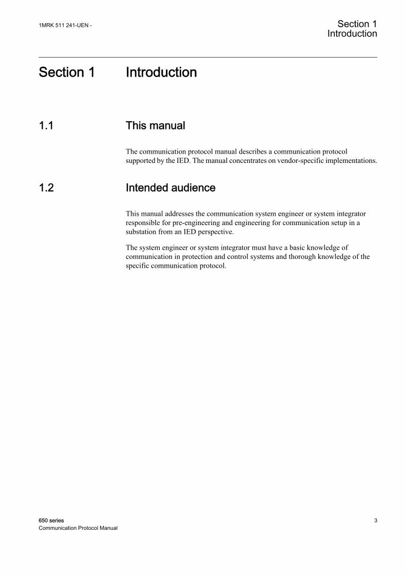
Figure 1: The intended use of manuals in different lifecycles
The engineering manual contains instructions on how to engineer the IEDs usingthe different tools in PCM600. The manual provides instructions on how to set up aPCM600 project and insert IEDs to the project structure. The manual alsorecommends a sequence for engineering of protection and control functions, LHMIfunctions as well as communication engineering for IEC 60870-5-103, IEC 61850and DNP3.
The installation manual contains instructions on how to install the IED. Themanual provides procedures for mechanical and electrical installation. The chaptersare organized in chronological order in which the IED should be installed.
The commissioning manual contains instructions on how to commission the IED.The manual can also be used by system engineers and maintenance personnel forassistance during the testing phase. The manual provides procedures for checkingof external circuitry and energizing the IED, parameter setting and configuration as
Section 1 1MRK 511 241-UEN -Introduction
4 650 seriesCommunication Protocol Manual
well as verifying settings by secondary injection. The manual describes the processof testing an IED in a substation which is not in service. The chapters are organizedin chronological order in which the IED should be commissioned.
The operation manual contains instructions on how to operate the IED once it hasbeen commissioned. The manual provides instructions for monitoring, controllingand setting the IED. The manual also describes how to identify disturbances andhow to view calculated and measured power grid data to determine the cause of afault.
The service manual contains instructions on how to service and maintain the IED.The manual also provides procedures for de-energizing, de-commissioning anddisposal of the IED.
The application manual contains application descriptions and setting guidelinessorted per function. The manual can be used to find out when and for what purposea typical protection function can be used. The manual can also be used whencalculating settings.
The technical manual contains application and functionality descriptions and listsfunction blocks, logic diagrams, input and output signals, setting parameters andtechnical data sorted per function. The manual can be used as a technical referenceduring the engineering phase, installation and commissioning phase, and duringnormal service.
The communication protocol manual describes a communication protocolsupported by the IED. The manual concentrates on vendor-specific implementations.
The point list manual describes the outlook and properties of the data pointsspecific to the IED. The manual should be used in conjunction with thecorresponding communication protocol manual.
The service manual is not available yet.
1.3.2 Document revision historyDocument revision/date Product series version History-/February 2011 1.1 First release
1.3.3 Related documentsDocuments related to REB650 Identity numberApplication manual 1MRK 505 262-UEN
Technical manual 1MRK 505 263-UEN
Commissioning manual 1MRK 505 264-UEN
Table continues on next page
1MRK 511 241-UEN - Section 1Introduction
650 series 5Communication Protocol Manual
Documents related to REB650 Identity numberProduct Guide, configured 1MRK 505 265-BEN
Type test certificate 1MRK 505 265-TEN
Documents related to REL650 Identity numberApplication manual 1MRK 506 325-UEN
Technical manual 1MRK 506 326-UEN
Commissioning manual 1MRK 506 327-UEN
Product Guide, configured 1MRK 506 328-BEN
Type test certificate 1MRK 506 328-TEN
Documents related to RET650 Identity numberApplication manual 1MRK 504 124-UEN
Technical manual 1MRK 504 125-UEN
Commissioning manual 1MRK 504 126-UEN
Product Guide, configured 1MRK 504 127-BEN
Type test certificate 1MRK 504 127-TEN
Documents related to REC650 Identity numberApplication manual 1MRK 511 246-UEN
Technical manual 1MRK 511 247-UEN
Commissioning manual 1MRK 511 248-UEN
Product Guide 1MRK 511 249-BEN
Type test certificate 1MRK 511 249-TEN
Documents related to REG650 Identity numberApplication manual 1MRK 502 033-UEN
Technical manual 1MRK 502 034-UEN
Commissioning manual 1MRK 502 035-UEN
Product Guide 1MRK 502 036-BEN
Type test certificate 1MRK 502 036-TEN
Rotor Earth Fault Protection with Injection Unit RXTTE4 and REG670 1MRG001910
Documents related to REQ650 Identity numberApplication manual 1MRK 505 266-UEN
Technical manual 1MRK 505 267-UEN
Commissioning manual 1MRK 505 268-UEN
Product Guide 1MRK 505 269-BEN
Type test certificate 1MRK 505 269-TEN
Section 1 1MRK 511 241-UEN -Introduction
6 650 seriesCommunication Protocol Manual
650 series manuals Identity numberCommunication protocol manual, DNP3 1MRK 511 241-UEN
Communication protocol manual, IEC 61850 1MRK 511 242-UEN
Communication protocol manual, IEC 60870-5-103 1MRK 511 243-UEN
Point list manual, DNP3 1MRK 511 244-UEN
Engineering manual 1MRK 511 245-UEN
Operation manual 1MRK 500 093-UEN
Installation manual 1MRK 514 014-UEN
1.4 Symbols and conventions
1.4.1 Safety indication symbols
The caution icon indicates important information or warning relatedto the concept discussed in the text. It might indicate the presenceof a hazard which could result in corruption of software or damageto equipment or property.
The information icon alerts the reader of important facts andconditions.
The tip icon indicates advice on, for example, how to design yourproject or how to use a certain function.
Although warning hazards are related to personal injury, it is necessary tounderstand that under certain operational conditions, operation of damagedequipment may result in degraded process performance leading to personal injuryor death. Therefore, comply fully with all warning and caution notices.
1.4.2 Manual conventionsConventions used in IED manuals. A particular convention may not be used in thismanual.
• Abbreviations and acronyms in this manual are spelled out in the glossary. Theglossary also contains definitions of important terms.
• Push button navigation in the LHMI menu structure is presented by using thepush button icons, for example:To navigate between the options, use and .
• HMI menu paths are presented in bold, for example:Select Main menu/Settings.
1MRK 511 241-UEN - Section 1Introduction
650 series 7Communication Protocol Manual
• LHMI messages are shown in Courier font, for example:To save the changes in non-volatile memory, select Yes and press .
• Parameter names are shown in italics, for example:The function can be enabled and disabled with the Operation setting.
• The ^ character in front of an input or output signal name in the function blocksymbol given for a function, indicates that the user can set an own signal namein PCM600.
• The * character after an input or output signal name in the function blocksymbol given for a function, indicates that the signal must be connected toanother function block in the application configuration to achieve a validapplication configuration.
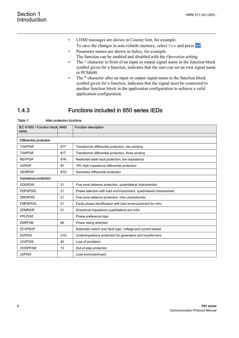
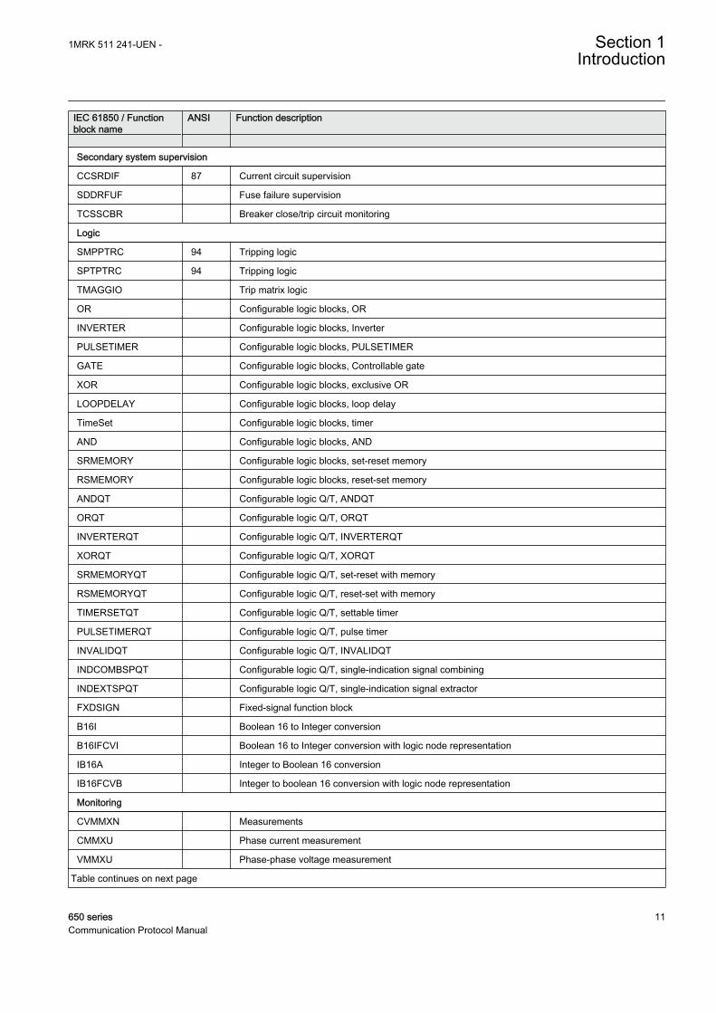
1.4.3 Functions included in 650 series IEDsTable 1: Main protection functions
IEC 61850 / Function blockname
ANSI Function description
Differential protection
T2WPDIF 87T Transformer differential protection, two winding
T3WPDIF 87T Transformer differential protection, three winding
REFPDIF 87N Restricted earth fault protection, low impedance
HZPDIF 87 1Ph High impedance differential protection
GENPDIF 87G Generator differential protection
Impedance protection
ZQDPDIS 21 Five-zone distance protection, quadrilateral characteristic
FDPSPDIS 21 Phase selection with load enchroachment, quadrilateral characteristic
ZMOPDIS 21 Five-zone distance protection, mho characteristic
FMPSPDIS 21 Faulty phase identification with load enchroachment for mho
ZDNRDIR 21 Directional impedance quadrilateral and mho
PPLPHIZ Phase preference logic
ZMRPSB 68 Power swing detection
ZCVPSOF Automatic switch onto fault logic, voltage-and current-based
ZGPDIS 21G Underimpedance protection for generators and transformers
LEXPDIS 40 Loss of excitation
OOSPPAM 13 Out-of-step protection
LEPDIS Load enchroachment
Section 1 1MRK 511 241-UEN -Introduction
8 650 seriesCommunication Protocol Manual
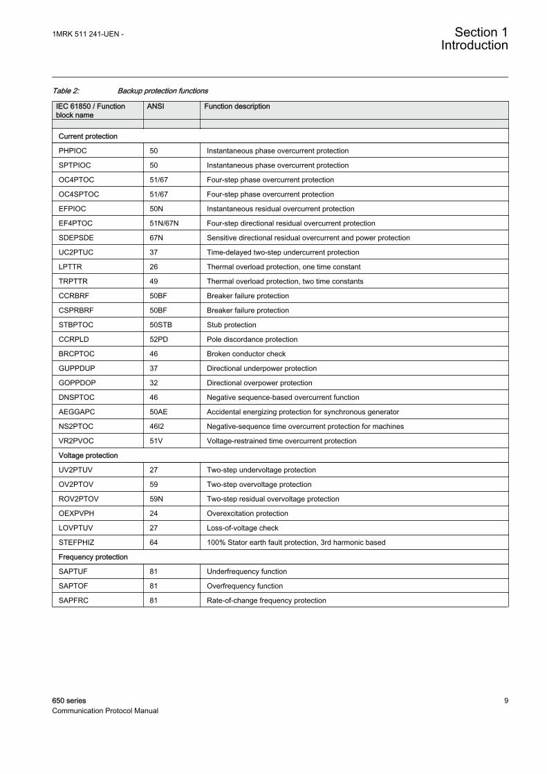
Table 2: Backup protection functions
IEC 61850 / Functionblock name
ANSI Function description
Current protection
PHPIOC 50 Instantaneous phase overcurrent protection
SPTPIOC 50 Instantaneous phase overcurrent protection
OC4PTOC 51/67 Four-step phase overcurrent protection
OC4SPTOC 51/67 Four-step phase overcurrent protection
EFPIOC 50N Instantaneous residual overcurrent protection
EF4PTOC 51N/67N Four-step directional residual overcurrent protection
SDEPSDE 67N Sensitive directional residual overcurrent and power protection
UC2PTUC 37 Time-delayed two-step undercurrent protection
LPTTR 26 Thermal overload protection, one time constant
TRPTTR 49 Thermal overload protection, two time constants
CCRBRF 50BF Breaker failure protection
CSPRBRF 50BF Breaker failure protection
STBPTOC 50STB Stub protection
CCRPLD 52PD Pole discordance protection
BRCPTOC 46 Broken conductor check
GUPPDUP 37 Directional underpower protection
GOPPDOP 32 Directional overpower protection
DNSPTOC 46 Negative sequence-based overcurrent function
AEGGAPC 50AE Accidental energizing protection for synchronous generator
NS2PTOC 46I2 Negative-sequence time overcurrent protection for machines
VR2PVOC 51V Voltage-restrained time overcurrent protection
Voltage protection
UV2PTUV 27 Two-step undervoltage protection
OV2PTOV 59 Two-step overvoltage protection
ROV2PTOV 59N Two-step residual overvoltage protection
OEXPVPH 24 Overexcitation protection
LOVPTUV 27 Loss-of-voltage check
STEFPHIZ 64 100% Stator earth fault protection, 3rd harmonic based
Frequency protection
SAPTUF 81 Underfrequency function
SAPTOF 81 Overfrequency function
SAPFRC 81 Rate-of-change frequency protection
1MRK 511 241-UEN - Section 1Introduction
650 series 9Communication Protocol Manual
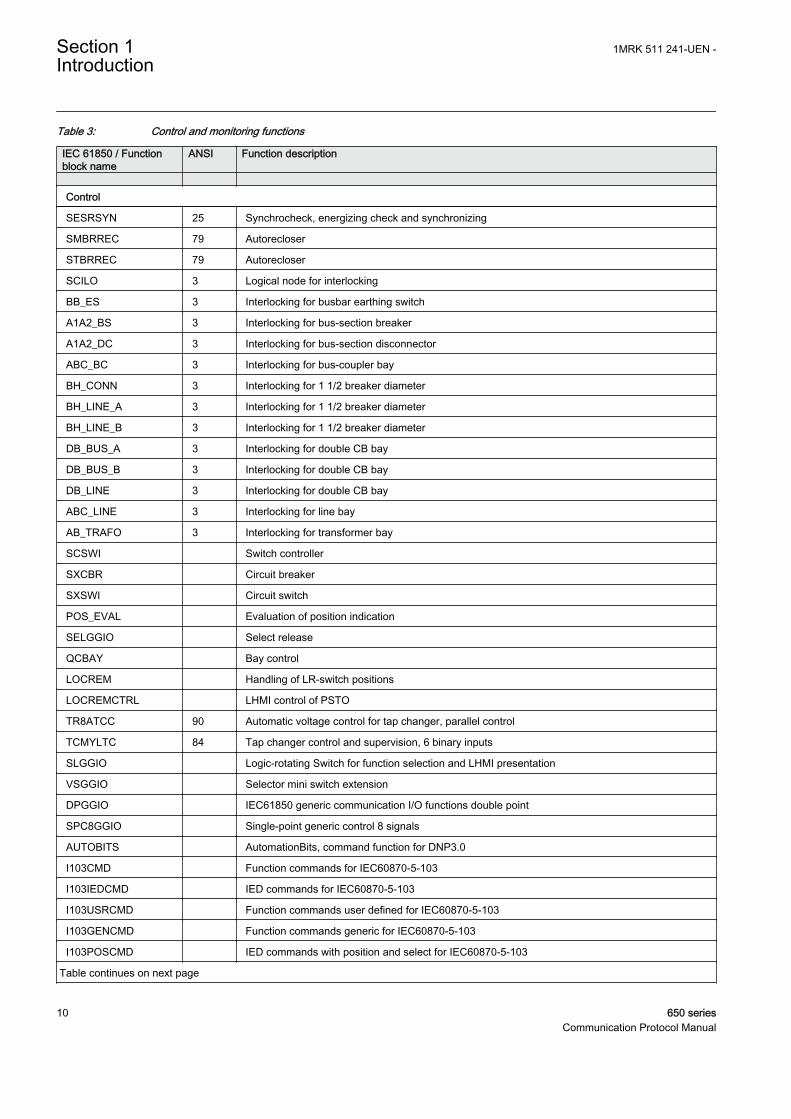
Table 3: Control and monitoring functions
IEC 61850 / Functionblock name
ANSI Function description
Control
SESRSYN 25 Synchrocheck, energizing check and synchronizing
SMBRREC 79 Autorecloser
STBRREC 79 Autorecloser
SCILO 3 Logical node for interlocking
BB_ES 3 Interlocking for busbar earthing switch
A1A2_BS 3 Interlocking for bus-section breaker
A1A2_DC 3 Interlocking for bus-section disconnector
ABC_BC 3 Interlocking for bus-coupler bay
BH_CONN 3 Interlocking for 1 1/2 breaker diameter
BH_LINE_A 3 Interlocking for 1 1/2 breaker diameter
BH_LINE_B 3 Interlocking for 1 1/2 breaker diameter
DB_BUS_A 3 Interlocking for double CB bay
DB_BUS_B 3 Interlocking for double CB bay
DB_LINE 3 Interlocking for double CB bay
ABC_LINE 3 Interlocking for line bay
AB_TRAFO 3 Interlocking for transformer bay
SCSWI Switch controller
SXCBR Circuit breaker
SXSWI Circuit switch
POS_EVAL Evaluation of position indication
SELGGIO Select release
QCBAY Bay control
LOCREM Handling of LR-switch positions
LOCREMCTRL LHMI control of PSTO
TR8ATCC 90 Automatic voltage control for tap changer, parallel control
TCMYLTC 84 Tap changer control and supervision, 6 binary inputs
SLGGIO Logic-rotating Switch for function selection and LHMI presentation
VSGGIO Selector mini switch extension
DPGGIO IEC61850 generic communication I/O functions double point
SPC8GGIO Single-point generic control 8 signals
AUTOBITS AutomationBits, command function for DNP3.0
I103CMD Function commands for IEC60870-5-103
I103IEDCMD IED commands for IEC60870-5-103
I103USRCMD Function commands user defined for IEC60870-5-103
I103GENCMD Function commands generic for IEC60870-5-103
I103POSCMD IED commands with position and select for IEC60870-5-103
Table continues on next page
Section 1 1MRK 511 241-UEN -Introduction
10 650 seriesCommunication Protocol Manual
IEC 61850 / Functionblock name
ANSI Function description
Secondary system supervision
CCSRDIF 87 Current circuit supervision
SDDRFUF Fuse failure supervision
TCSSCBR Breaker close/trip circuit monitoring
Logic
SMPPTRC 94 Tripping logic
SPTPTRC 94 Tripping logic
TMAGGIO Trip matrix logic
OR Configurable logic blocks, OR
INVERTER Configurable logic blocks, Inverter
PULSETIMER Configurable logic blocks, PULSETIMER
GATE Configurable logic blocks, Controllable gate
XOR Configurable logic blocks, exclusive OR
LOOPDELAY Configurable logic blocks, loop delay
TimeSet Configurable logic blocks, timer
AND Configurable logic blocks, AND
SRMEMORY Configurable logic blocks, set-reset memory
RSMEMORY Configurable logic blocks, reset-set memory
ANDQT Configurable logic Q/T, ANDQT
ORQT Configurable logic Q/T, ORQT
INVERTERQT Configurable logic Q/T, INVERTERQT
XORQT Configurable logic Q/T, XORQT
SRMEMORYQT Configurable logic Q/T, set-reset with memory
RSMEMORYQT Configurable logic Q/T, reset-set with memory
TIMERSETQT Configurable logic Q/T, settable timer
PULSETIMERQT Configurable logic Q/T, pulse timer
INVALIDQT Configurable logic Q/T, INVALIDQT
INDCOMBSPQT Configurable logic Q/T, single-indication signal combining
INDEXTSPQT Configurable logic Q/T, single-indication signal extractor
FXDSIGN Fixed-signal function block
B16I Boolean 16 to Integer conversion
B16IFCVI Boolean 16 to Integer conversion with logic node representation
IB16A Integer to Boolean 16 conversion
IB16FCVB Integer to boolean 16 conversion with logic node representation
Monitoring
CVMMXN Measurements
CMMXU Phase current measurement
VMMXU Phase-phase voltage measurement
Table continues on next page
1MRK 511 241-UEN - Section 1Introduction
650 series 11Communication Protocol Manual
IEC 61850 / Functionblock name
ANSI Function description
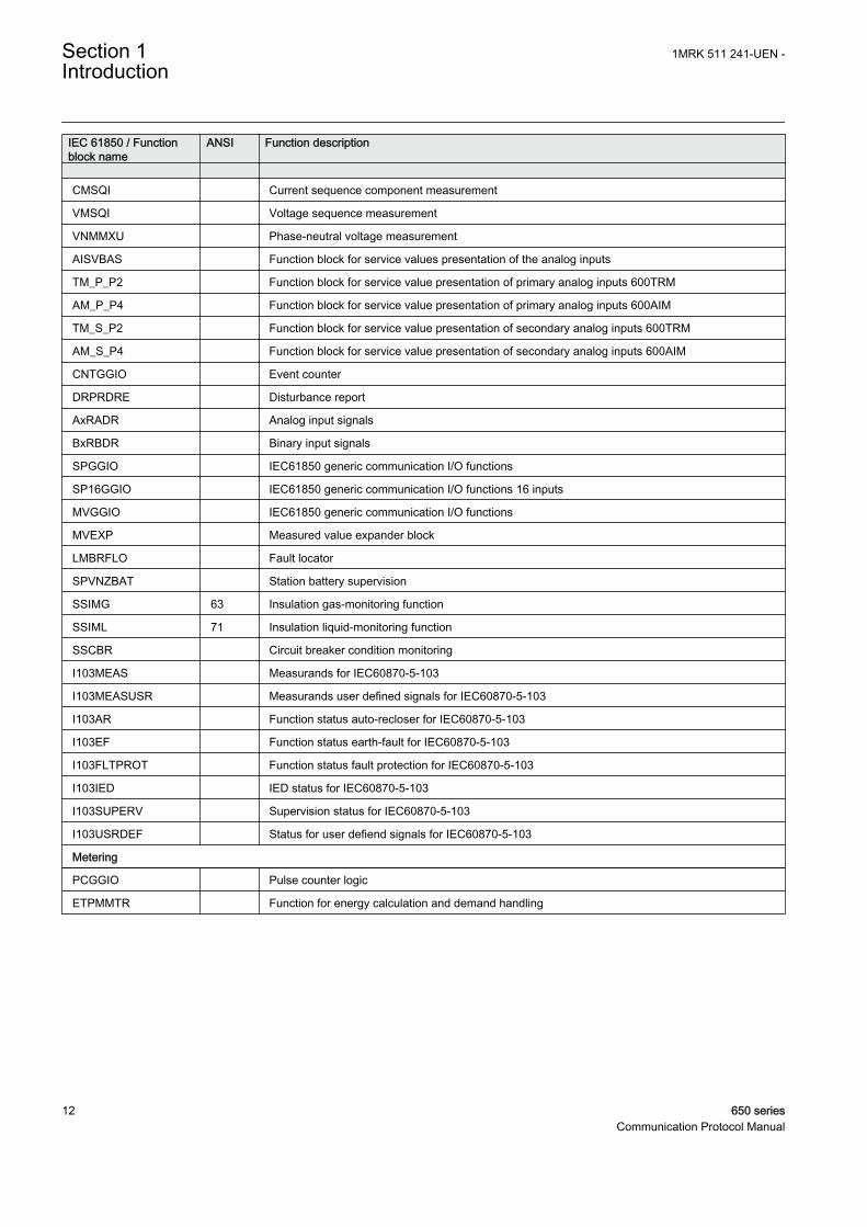
CMSQI Current sequence component measurement
VMSQI Voltage sequence measurement
VNMMXU Phase-neutral voltage measurement
AISVBAS Function block for service values presentation of the analog inputs
TM_P_P2 Function block for service value presentation of primary analog inputs 600TRM
AM_P_P4 Function block for service value presentation of primary analog inputs 600AIM
TM_S_P2 Function block for service value presentation of secondary analog inputs 600TRM
AM_S_P4 Function block for service value presentation of secondary analog inputs 600AIM
CNTGGIO Event counter
DRPRDRE Disturbance report
AxRADR Analog input signals
BxRBDR Binary input signals
SPGGIO IEC61850 generic communication I/O functions
SP16GGIO IEC61850 generic communication I/O functions 16 inputs
MVGGIO IEC61850 generic communication I/O functions
MVEXP Measured value expander block
LMBRFLO Fault locator
SPVNZBAT Station battery supervision
SSIMG 63 Insulation gas-monitoring function
SSIML 71 Insulation liquid-monitoring function
SSCBR Circuit breaker condition monitoring
I103MEAS Measurands for IEC60870-5-103
I103MEASUSR Measurands user defined signals for IEC60870-5-103
I103AR Function status auto-recloser for IEC60870-5-103
I103EF Function status earth-fault for IEC60870-5-103
I103FLTPROT Function status fault protection for IEC60870-5-103
I103IED IED status for IEC60870-5-103
I103SUPERV Supervision status for IEC60870-5-103
I103USRDEF Status for user defiend signals for IEC60870-5-103
Metering
PCGGIO Pulse counter logic
ETPMMTR Function for energy calculation and demand handling
Section 1 1MRK 511 241-UEN -Introduction
12 650 seriesCommunication Protocol Manual
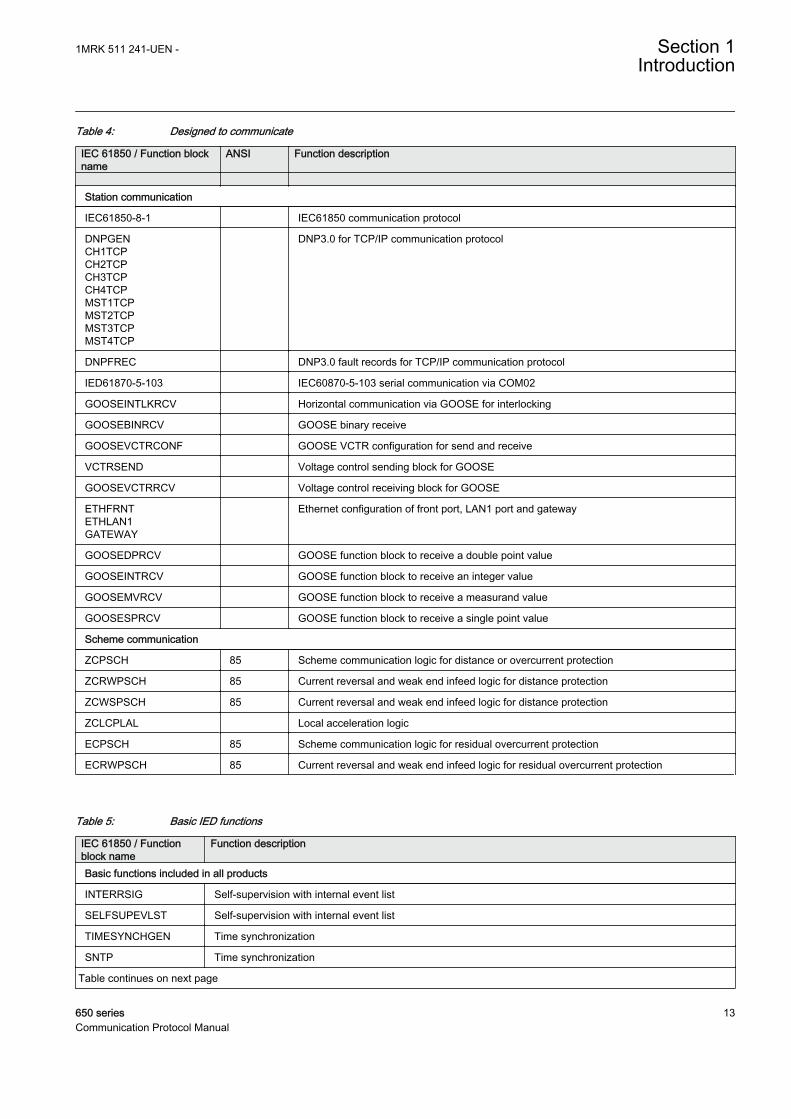
Table 4: Designed to communicate
IEC 61850 / Function blockname
ANSI Function description
Station communication
IEC61850-8-1 IEC61850 communication protocol
DNPGENCH1TCPCH2TCPCH3TCPCH4TCPMST1TCPMST2TCPMST3TCPMST4TCP
DNP3.0 for TCP/IP communication protocol
DNPFREC DNP3.0 fault records for TCP/IP communication protocol
IED61870-5-103 IEC60870-5-103 serial communication via COM02
GOOSEINTLKRCV Horizontal communication via GOOSE for interlocking
GOOSEBINRCV GOOSE binary receive
GOOSEVCTRCONF GOOSE VCTR configuration for send and receive
VCTRSEND Voltage control sending block for GOOSE
GOOSEVCTRRCV Voltage control receiving block for GOOSE
ETHFRNTETHLAN1GATEWAY
Ethernet configuration of front port, LAN1 port and gateway
GOOSEDPRCV GOOSE function block to receive a double point value
GOOSEINTRCV GOOSE function block to receive an integer value
GOOSEMVRCV GOOSE function block to receive a measurand value
GOOSESPRCV GOOSE function block to receive a single point value
Scheme communication
ZCPSCH 85 Scheme communication logic for distance or overcurrent protection
ZCRWPSCH 85 Current reversal and weak end infeed logic for distance protection
ZCWSPSCH 85 Current reversal and weak end infeed logic for distance protection
ZCLCPLAL Local acceleration logic
ECPSCH 85 Scheme communication logic for residual overcurrent protection
ECRWPSCH 85 Current reversal and weak end infeed logic for residual overcurrent protection
Table 5: Basic IED functions
IEC 61850 / Functionblock name
Function description
Basic functions included in all products
INTERRSIG Self-supervision with internal event list
SELFSUPEVLST Self-supervision with internal event list
TIMESYNCHGEN Time synchronization
SNTP Time synchronization
Table continues on next page
1MRK 511 241-UEN - Section 1Introduction
650 series 13Communication Protocol Manual
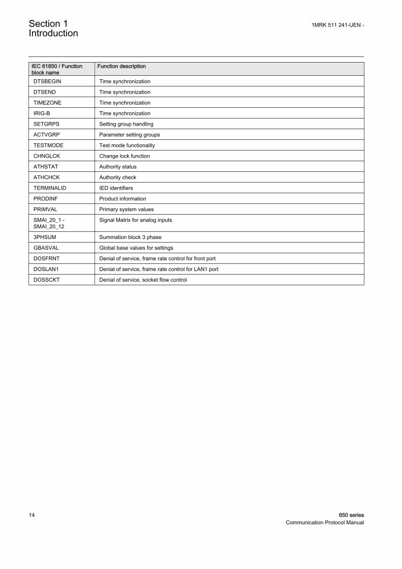
IEC 61850 / Functionblock name
Function description
DTSBEGIN Time synchronization
DTSEND Time synchronization
TIMEZONE Time synchronization
IRIG-B Time synchronization
SETGRPS Setting group handling
ACTVGRP Parameter setting groups
TESTMODE Test mode functionality
CHNGLCK Change lock function
ATHSTAT Authority status
ATHCHCK Authority check
TERMINALID IED identifiers
PRODINF Product information
PRIMVAL Primary system values
SMAI_20_1 -SMAI_20_12
Signal Matrix for analog inputs
3PHSUM Summation block 3 phase
GBASVAL Global base values for settings
DOSFRNT Denial of service, frame rate control for front port
DOSLAN1 Denial of service, frame rate control for LAN1 port
DOSSCKT Denial of service, socket flow control
Section 1 1MRK 511 241-UEN -Introduction
14 650 seriesCommunication Protocol Manual
Section 2 DNP3 overview
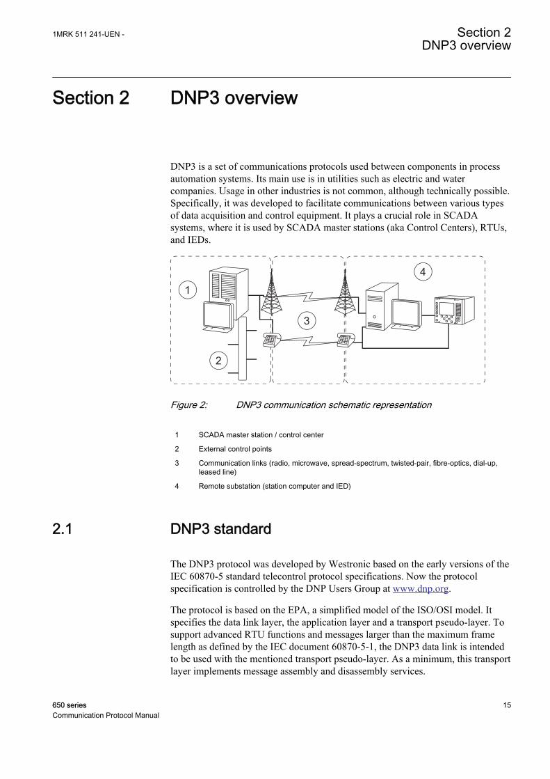
DNP3 is a set of communications protocols used between components in processautomation systems. Its main use is in utilities such as electric and watercompanies. Usage in other industries is not common, although technically possible.Specifically, it was developed to facilitate communications between various typesof data acquisition and control equipment. It plays a crucial role in SCADAsystems, where it is used by SCADA master stations (aka Control Centers), RTUs,and IEDs.
GUID-F3F7289C-3344-492F-8779-D63CBF6B469A V1 EN
Figure 2: DNP3 communication schematic representation
1 SCADA master station / control center
2 External control points
3 Communication links (radio, microwave, spread-spectrum, twisted-pair, fibre-optics, dial-up,leased line)
4 Remote substation (station computer and IED)
2.1 DNP3 standard
The DNP3 protocol was developed by Westronic based on the early versions of theIEC 60870-5 standard telecontrol protocol specifications. Now the protocolspecification is controlled by the DNP Users Group at www.dnp.org.
The protocol is based on the EPA, a simplified model of the ISO/OSI model. Itspecifies the data link layer, the application layer and a transport pseudo-layer. Tosupport advanced RTU functions and messages larger than the maximum framelength as defined by the IEC document 60870-5-1, the DNP3 data link is intendedto be used with the mentioned transport pseudo-layer. As a minimum, this transportlayer implements message assembly and disassembly services.
1MRK 511 241-UEN - Section 2DNP3 overview
650 series 15Communication Protocol Manual
Physical layerEven though the standard does not specify the physical layer, it does howeverspecify how to operate in a networked environment and also suggests how to avoidcollisions between simultaneously sending devices.
Many implementations use serial communication based on RS-232, RS-485 oreven fibre optics.
DNP3 can also be used over packet-oriented networks such as TCP/IP and UDP inwhich, for example, Ethernet may be used. In this case DNP3 can be said to betunneled over TCP/IP or UDP.
Additional information on the DNP3 physical layer is available atthe DNP Users Group at www.dnp.org.
Data link layerThe DNP3 data link layer is designed to operate with asynchronous or synchronousbit serial physical layers. Fully balanced transmission procedures were adopted tosupport spontaneous transmissions from outstations.
Data link functions include:
• Performing message data link retransmissions.• Synchronizing and handling the FCB in the control octet.• Setting and clearing the DFC bit based on buffer availability.• Packing user data into the defined frame format includes CRC and transmitting
the data to the physical layer.• Unpacking the data link frame received from the physical layer into user data,
checking and removing CRC.• Controlling the physical layer.• Responding to all valid frames received from the physical layer.
Data link responsibilities:
• Exchange of SDUs between peer DNP3 data links• Error notification to data link user• Sequencing of SDUs• SDU delivery quality.
Link-layer confirm usage is not recommended and the implementation is optional.The IED does not request data-link layer confirmations for TCP/IP communication.
See the DNP technical bulletin TB1998-0402, section 3 for detailsat www.dnp.org.
Section 2 1MRK 511 241-UEN -DNP3 overview
16 650 seriesCommunication Protocol Manual
Transport pseudo-layerTo support advanced RTU functions and messages exceeding the maximum datalink frame length, a transport pseudo-layer which implements message assemblyand disassembly services was adopted.
Transport functions:
• Fragmenting user data into one or more data link frames and transmitting thedata to the data link layer
• Assembling the data link frames received from the data link layer into user data• Controlling all aspects of the data link excluding data link configuration
Transport responsibilities:
• Exchange of SDUs between peer DNP3 transport pseudo layers• Error notification to transport users• Sequencing of SDUs
Application layerThe application layer is responsible for performing operations on data objectsdefined by the device or on the device itself. These operations include returningactual values (read function), assigning new values (write function) if the objectrepresents control points, arming and energizing the output point (select, operate ordirect operate functions) and if counters are used, reading actual values andclearing the counters. DNP3 uses the term point do identify an entity, and theseentities can be categorized into point-types, such as analogs or binaries. Points areaddressed by giving them an index number and an object is a formattedrepresentation of data from a point. These objects can be assigned to classes inorder to organize events and current values into categories. The DNP3 protocoldefines four classes; 0 for static data (current value) and 1, 2 and 3 for event data.
Communication modesThe IED supports four DNP3 communication modes.
• Quiescent operation• Unsolicited report-by-exception operation• Polled report-by-exception operation• Polled static operation
2.2 Documentation
This implementation of DNP3 is fully compliant with DNP3 Subset DefinitionLevel 2, and contains significant functionality beyond Subset Level 2. See thedevice profile for further information.
1MRK 511 241-UEN - Section 2DNP3 overview
650 series 17Communication Protocol Manual

18
Section 3 Vendor-specific implementation
3.1 DNP3 link modes
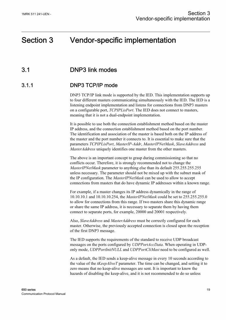
3.1.1 DNP3 TCP/IP modeDNP3 TCP/IP link mode is supported by the IED. This implementation supports upto four different masters communicating simultaneously with the IED. The IED is alistening endpoint implementation and listens for connections from DNP3 masterson a configurable port, TCPIPLisPort. The IED does not connect to masters,meaning that it is not a dual-endpoint implementation.
It is possible to use both the connection establishment method based on the masterIP address, and the connection establishment method based on the port number.The identification and association of the master is based both on the IP address ofthe master and the port number it connects to. It is essential to make sure that theparameters TCPIPLisPort, MasterIP-Addr, MasterIPNetMask, SlaveAddress andMasterAddress uniquely identifies one master from the other masters.
The above is an important concept to grasp during commissioning so that noconflicts occur. Therefore, it is strongly recommended not to change theMasterIPNetMask parameter to anything else than its default 255.255.255.255unless necessary. The parameter should not be mixed up with the subnet mask ofthe IP configuration. The MasterIPNetMask can be used to allow to acceptconnections from masters that do have dynamic IP addresses within a known range.
For example, if a master changes its IP address dynamically in the range of10.10.10.1 and 10.10.10.254, the MasterIPNetMask could be set to 255.255.255.0to allow for connections from this range. If two masters share this dynamic rangeor share the same IP address, it is necessary to separate them by having themconnect to separate ports, for example, 20000 and 20001 respectively.
Also, SlaveAddress and MasterAddress must be correctly configured for eachmaster. Otherwise, the previously accepted connection is closed upon the receptionof the first DNP3 message.
The IED supports the requirements of the standard to receive UDP broadcastmessages on the ports configured by UDPPortAccData. When operating in UDP-only mode, UDPPortInitNULL and UDPPortCliMast need to be configured as well.
As a default, the IED sends a keep-alive message in every 10 seconds according tothe value of the tKeepAliveT parameter. The time can be changed, and setting it tozero means that no keep-alive messages are sent. It is important to know thehazards of disabling the keep-alive, and it is not recommended to do so unless
1MRK 511 241-UEN - Section 3Vendor-specific implementation
650 series 19Communication Protocol Manual
necessary. If the keep-alive messages are unwanted, it is better to increase thevalue of tKeepAliveT so that it exceeds the master's poll rate.
If a master crashes or the communication links are broken and the master restarts,the TCP/IP makes the IED believe that the connection still exists. Since the IEDconforms to the recommendations of the standard not to accept new connectionswhen a connection already exists to the particular master, the master will never beallowed to connect again. Another parameter that concerns the TCP/IP connectionstatus is tBrokenConTout. It determines how long a session is active after a TCP/IPconnection has been broken. After the time period, the session becomes inactiveand events are not stored. If the parameter is set to 0, events are stored until thesequential buffers overflow. Note that if the parameter is set to zero, all eventsfrom start-up until the sequential buffers overflow are saved even though noconnection would have been established.
Further documentation concerning DNP3 TCP/IP communication is available inthe IP Networking document Volume 7, from www.dnp.org.
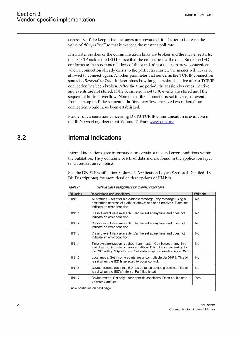
3.2 Internal indications
Internal indications give information on certain status and error conditions withinthe outstation. They contain 2 octets of data and are found in the application layeron an outstation response.
See the DNP3 Specification Volume 3 Application Layer (Section 5 Detailed IINBit Descriptions) for more detailed descriptions of IIN bits.
Table 6: Default class assignment for internal indications
Bit index Descriptions and conditions WritableIIN1.0 All stations – set after a broadcast message (any message using a
destination address of 0xfff0 or above) has been received. Does notindicate an error condition
No
IIN1.1 Class 1 event data available. Can be set at any time and does notindicate an error condition.
No
IIN1.2 Class 2 event data available. Can be set at any time and does notindicate an error condition
No
IIN1.3 Class 3 event data available. Can be set at any time and does notindicate an error condition
No
IIN1.4 Time synchronization required from master. Can be set at any timeand does not indicate an error condition. This bit is set according tothe PST setting “tSyncTimeout” when time synchronization is via DNP3.
No
IIN1.5 Local mode. Set if some points are uncontrollable via DNP3. This bitis set when the IED is selected to Local control.
No
IIN1.6 Device trouble. Set if the IED has detected device problems. This bitis set when the IED’s “Internal Fail” flag is set
No
IIN1.7 Device restart. Set only under specific conditions. Does not indicatean error condition
Yes
Table continues on next page
Section 3 1MRK 511 241-UEN -Vendor-specific implementation
20 650 seriesCommunication Protocol Manual
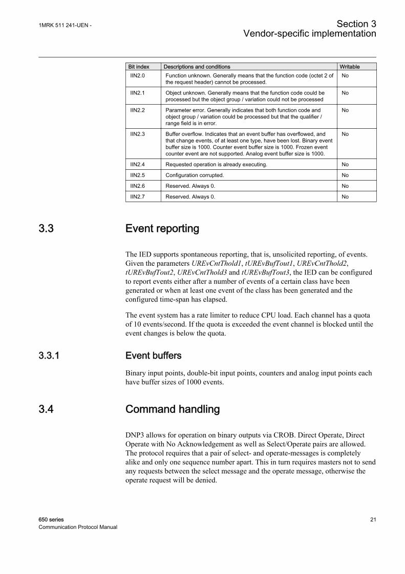
Bit index Descriptions and conditions WritableIIN2.0 Function unknown. Generally means that the function code (octet 2 of
the request header) cannot be processed.No
IIN2.1 Object unknown. Generally means that the function code could beprocessed but the object group / variation could not be processed
No
IIN2.2 Parameter error. Generally indicates that both function code andobject group / variation could be processed but that the qualifier /range field is in error.
No
IIN2.3 Buffer overflow. Indicates that an event buffer has overflowed, andthat change events, of at least one type, have been lost. Binary eventbuffer size is 1000. Counter event buffer size is 1000. Frozen eventcounter event are not supported. Analog event buffer size is 1000.
No
IIN2.4 Requested operation is already executing. No
IIN2.5 Configuration corrupted. No
IIN2.6 Reserved. Always 0. No
IIN2.7 Reserved. Always 0. No
3.3 Event reporting
The IED supports spontaneous reporting, that is, unsolicited reporting, of events.Given the parameters UREvCntThold1, tUREvBufTout1, UREvCntThold2,tUREvBufTout2, UREvCntThold3 and tUREvBufTout3, the IED can be configuredto report events either after a number of events of a certain class have beengenerated or when at least one event of the class has been generated and theconfigured time-span has elapsed.
The event system has a rate limiter to reduce CPU load. Each channel has a quotaof 10 events/second. If the quota is exceeded the event channel is blocked until theevent changes is below the quota.
3.3.1 Event buffersBinary input points, double-bit input points, counters and analog input points eachhave buffer sizes of 1000 events.
3.4 Command handling
DNP3 allows for operation on binary outputs via CROB. Direct Operate, DirectOperate with No Acknowledgement as well as Select/Operate pairs are allowed.The protocol requires that a pair of select- and operate-messages is completelyalike and only one sequence number apart. This in turn requires masters not to sendany requests between the select message and the operate message, otherwise theoperate request will be denied.
1MRK 511 241-UEN - Section 3Vendor-specific implementation
650 series 21Communication Protocol Manual
Select and Operate requests may contain multiple objects. The select/control buffersize is large enough to hold 10 of the largest select requests possible.
3.4.1 Automation bitsAutomation bit signals can be used to interpret and execute the count, on-time andoff-time parameters of a CROB. Thereby pulse trains of different characteristicsand lengths can be generated, and the outputs from the automation bits componentcan be connected to other function blocks in PCM600.
3.4.2 Apparatus controlApparatuses can be controlled via DNP3. Open and close points to SCSWI areavailable for mapping in PCM600. These points can then be written to by asCROBs, thereby opening or closing the breaker. It is important to note that thecontrol model, ctlModel, of the SCSWI is respected when set to SBO Enh. IfctlModel is set to SBO Enh, direct operate commands from DNP3 are not allowed.On the other hand, if ctlModel is set to Dir Norm, SBO commands from DNP3 areallowed.
Furthermore, the select timeout parameter tSelectTimeout in DNP3 should be set sothat it harmonizes with the tSelect parameter of the SCSWI. The shortest of the twoparameters dictates the timing of select/operate.
3.4.3 Binary output status points and control relay output blocksWhile BOS points are included here for completeness, they are not often polled byDNP3 masters. BOS points represent the most recent value from a commandoperation for the corresponding CROB point. BOS points are not recommended tobe included in class 0 polls.
As an alternative, it is recommended that actual status values affected by CROBpoints should be mapped as BI or DI. Requesting CROBs on the Open and Closepoints of SCSWI operate the breaker. The operation may take several seconds tocomplete. This means that a success response from the operate command may havebeen returned from the CROB even though the operation is still in progress.Therefore, the mentioned outputs from, for example, SCSWI need to be monitoredas a complement.
This implies that the binary output object should not be assigned to classes 1, 2 or3. A read of the binary outputs returns the last value written to that output.
3.5 Time synchronization
DNP3 supports time synchronization of the IED via object numbers 50...52. Timesynchronization via DNP3 should only be used if time source with better accuracy
Section 3 1MRK 511 241-UEN -Vendor-specific implementation
22 650 seriesCommunication Protocol Manual
is not available, for example, IRIG-B, GPS or SNTP. For TCP/IP channels, theLAN procedure should be used, in which two separate messages are transmittedfrom the master, record current time and write, see DNP3 Specification Volume 5for more information.
Parameters have to be set among the system wide time parametersas well as among the individual DNP3 masters.
DNP3 can be set for a coarse synchronization source under Configuration/Time/Synchronisation/TimeSynch/CoarseSyncSrc in the LHMI tree. Note that whenDNP3 is set as coarse synchronization source, no fine synchronization source shallbe configured. Otherwise, the time will jump between the fine and the coarsesynchronization time sources.
Each DNP3 master configuration block has a number of parameters that affect thetime synchronization. Only one master at a time is configured to set the time in theIED. Therefore, only one master configuration block enables the DNPToSetTimeand TSyncReqAfTout parameter. That is, both parameters must have the same valueand should only be set for one master at a time.
The tSyncTimeout parameter defines how long after a successful timesynchronization the NeedTime IIN bit has to be set. The tSyncReqAfTout parameterdefines if the tSyncTimeout should be used or not. Also, the IED supports both thenew standard directive of use of UTC and local time for backward compatibility(ExtTimeFormat). If UTC is selected, the time in the time synchronizationmessages is expected to be in UTC, and vice versa.
3.6 Analog inputs
It is important to note that 16-bit and 32-bit variations of analog inputs aretransmitted through DNP3 as signed numbers. The default analog input eventbuffer size is set 1000.
3.6.1 Analog data scalingThe four scaling options associated with analog input data reporting are None,Ratio, Multiplicative and Divisor. The selection None means that no scaling isperformed on the source IEC 61850 value. The value is reported as such to DNP3.
Ratio, multiplicative and divisor scaling methodsThe PCM600 tool contains four value arguments related to the scaling methods:sourceMinVal, sourceMaxVal, destMinVal and destMaxVal. The use of thesearguments differs depending on the scaling method.
The ratio, multiplicative and divisor scaling methods use the first two arguments,souceMinVal and sourceMaxVal, to define the source value range inside which the
1MRK 511 241-UEN - Section 3Vendor-specific implementation
650 series 23Communication Protocol Manual
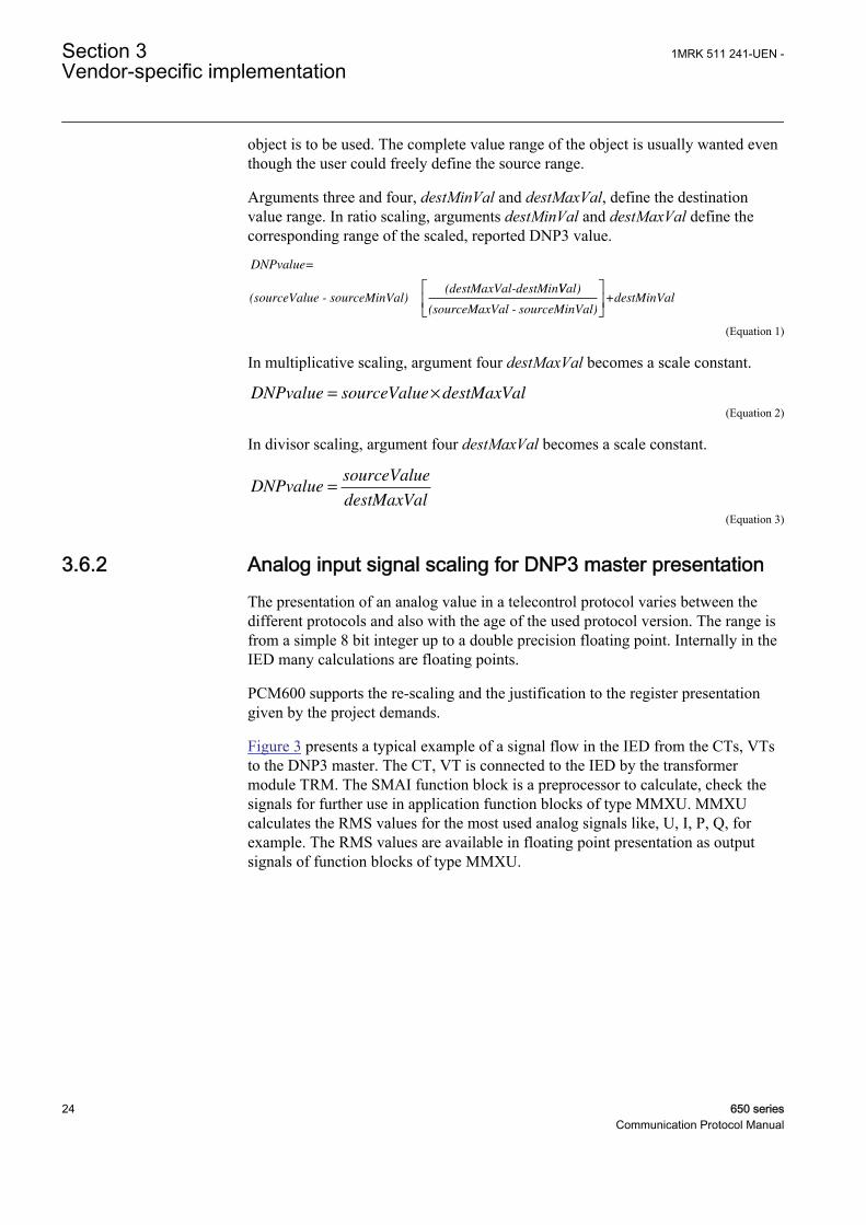
object is to be used. The complete value range of the object is usually wanted eventhough the user could freely define the source range.
Arguments three and four, destMinVal and destMaxVal, define the destinationvalue range. In ratio scaling, arguments destMinVal and destMaxVal define thecorresponding range of the scaled, reported DNP3 value.
DNPvalue=
(sourceValue - sourceMinVal) ×(destMaxVal-destMinVVal)
+destMinVal(sourceMaxVal - sourceMinVal)
GUID-9F985816-2268-412A-AE24-ED90EAC44AD7 V2 EN (Equation 1)
In multiplicative scaling, argument four destMaxVal becomes a scale constant.
DNPvalue sourceValue destMaxVal= ×
GUID-6AE38BAE-8FD6-44DD-9D53-45BE7AB121FF V1 EN (Equation 2)
In divisor scaling, argument four destMaxVal becomes a scale constant.
DNPvaluesourceValue
destMaxVal=
GUID-35F9E774-67FF-4257-8BA1-6D2E2CB4EC57 V1 EN (Equation 3)
3.6.2 Analog input signal scaling for DNP3 master presentationThe presentation of an analog value in a telecontrol protocol varies between thedifferent protocols and also with the age of the used protocol version. The range isfrom a simple 8 bit integer up to a double precision floating point. Internally in theIED many calculations are floating points.
PCM600 supports the re-scaling and the justification to the register presentationgiven by the project demands.
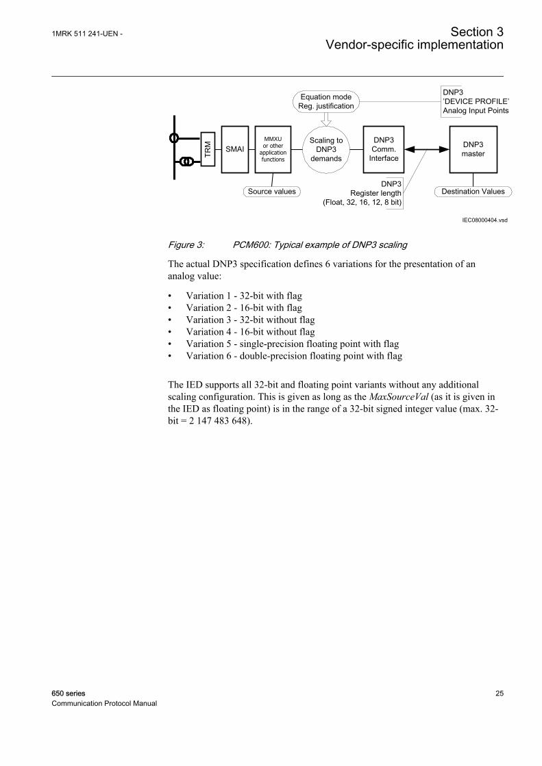
Figure 3 presents a typical example of a signal flow in the IED from the CTs, VTsto the DNP3 master. The CT, VT is connected to the IED by the transformermodule TRM. The SMAI function block is a preprocessor to calculate, check thesignals for further use in application function blocks of type MMXU. MMXUcalculates the RMS values for the most used analog signals like, U, I, P, Q, forexample. The RMS values are available in floating point presentation as outputsignals of function blocks of type MMXU.
Section 3 1MRK 511 241-UEN -Vendor-specific implementation
24 650 seriesCommunication Protocol Manual
IEC08000404.vsd
SMAIMMXU or other
application functions
DNP3master
DNP3Comm.
Interface
Scaling toDNP3
demands
Source values Destination Values
Equation modeReg. justification
DNP3 ’DEVICE PROFILE’Analog Input Points
DNP3 Register length
(Float, 32, 16, 12, 8 bit)TR
M
IEC08000404 V1 EN
Figure 3: PCM600: Typical example of DNP3 scaling
The actual DNP3 specification defines 6 variations for the presentation of ananalog value:
• Variation 1 - 32-bit with flag• Variation 2 - 16-bit with flag• Variation 3 - 32-bit without flag• Variation 4 - 16-bit without flag• Variation 5 - single-precision floating point with flag• Variation 6 - double-precision floating point with flag
The IED supports all 32-bit and floating point variants without any additionalscaling configuration. This is given as long as the MaxSourceVal (as it is given inthe IED as floating point) is in the range of a 32-bit signed integer value (max. 32-bit = 2 147 483 648).
1MRK 511 241-UEN - Section 3Vendor-specific implementation
650 series 25Communication Protocol Manual
IEC08000407.vsd
DNP3 AI scaling
DNP3 =Float or 32 bit
Value = angle+ 32 bit
Do AI scaling in’DNP3
for all AI types and variantsGet MinDestValue and
MaxDestValue for CMT AI scaling
Get MinSourceValue and MaxSourceValue
from PST for all AIs
Calculate Scaling factor on base of SourceValue and DestValue
and define Equation mode
Configure’Configuration Table’
in CMT for all AI values
AllDNP3 clients
done
Scale Ratio to degree and resolution
for all angle AI values
Select nextDNP3 client
END
DNP3-Register = 16, 12 or 8 bit
YES
NO
NO
A
IEC08000407 V2 EN
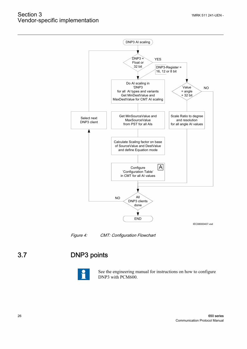
Figure 4: CMT: Configuration Flowchart
3.7 DNP3 points
See the engineering manual for instructions on how to configureDNP3 with PCM600.
Section 3 1MRK 511 241-UEN -Vendor-specific implementation
26 650 seriesCommunication Protocol Manual
3.7.1 Point configurationThe DNP3 point map is configurable in PCM600. All points in the IED areunmapped as default. In PCM600, the unmapped points in the variables list on theleft may be inserted to the active point list on the right.
Point gaps may be inserted if wanted. Point gaps cannot be read by the client.
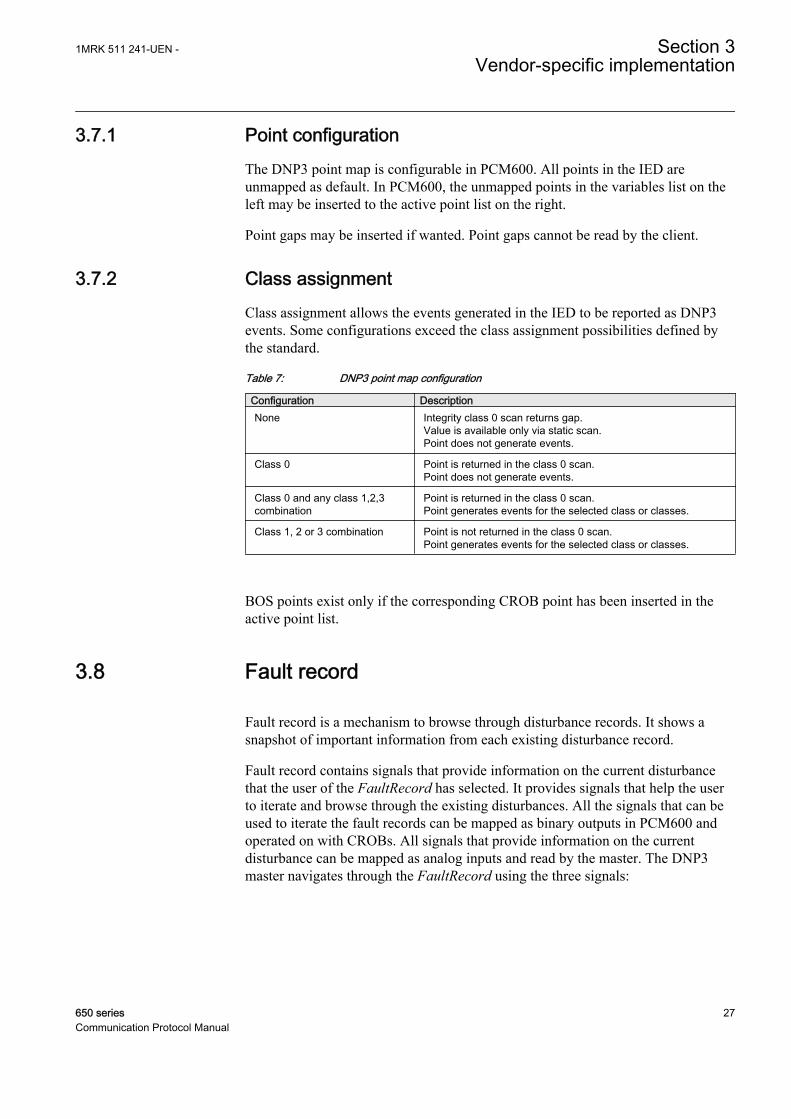
3.7.2 Class assignmentClass assignment allows the events generated in the IED to be reported as DNP3events. Some configurations exceed the class assignment possibilities defined bythe standard.
Table 7: DNP3 point map configuration
Configuration DescriptionNone Integrity class 0 scan returns gap.
Value is available only via static scan.Point does not generate events.
Class 0 Point is returned in the class 0 scan.Point does not generate events.
Class 0 and any class 1,2,3combination
Point is returned in the class 0 scan.Point generates events for the selected class or classes.
Class 1, 2 or 3 combination Point is not returned in the class 0 scan.Point generates events for the selected class or classes.
BOS points exist only if the corresponding CROB point has been inserted in theactive point list.
3.8 Fault record
Fault record is a mechanism to browse through disturbance records. It shows asnapshot of important information from each existing disturbance record.
Fault record contains signals that provide information on the current disturbancethat the user of the FaultRecord has selected. It provides signals that help the userto iterate and browse through the existing disturbances. All the signals that can beused to iterate the fault records can be mapped as binary outputs in PCM600 andoperated on with CROBs. All signals that provide information on the currentdisturbance can be mapped as analog inputs and read by the master. The DNP3master navigates through the FaultRecord using the three signals:
1MRK 511 241-UEN - Section 3Vendor-specific implementation
650 series 27Communication Protocol Manual
• GetFirstRec fetches the oldest record in the FaultRecord.• GetNextRec fetches the next record in time in the FaultRecord relative to the
previously fetched record. If the previously fetched record is the newest, nofetch is done.
• GetPrevRec fetches the previous record in time in the FaultRecord relative tothe previously fetched record. If the previously fetched record is the oldest, nofetch is done.
When a new disturbance is recorded, and the outputs are mapped to one of theevent classes, events are generated, but the navigation in the FaultRecord is notaffected. Hence, when the next command is sent from the DNP3 master, thefetched position is relative to the last fetch done; the position in the FaultRecordbefore the new disturbance occurred.
The output signals provide the fault record number, which is the number of thedisturbance in the LHMI or PCM600, the number of faults in the IED, the activesetting group at the time of the disturbance recording, the trigger signal identity,the time stamp at the trigger time as well as the fault location and the fault type. Inaddition, the magnitude, angle, fault magnitude and fault angle are provided for upto 30 of the analog channels connected to the disturbance recorder, and for the last10 analog channels, the calculated value at the trigger time is provided.
Section 3 1MRK 511 241-UEN -Vendor-specific implementation
28 650 seriesCommunication Protocol Manual
Section 4 DNP3 parameters
4.1 Parameter descriptions
The DNP3 parameters for a specific IED can be accessed with PCM600 via IEDConfiguration/Station Communication/DNP3.0. There is one general setting forDNP3 (Disabled/Enabled) and specific settings for each communication TCP/IPchannel, for example, CH1TCP and MST1TCP.
The DNP3 block contains one single parameter that controls the operation ofDNP3. This parameter must be turned on for the other parameters to have effect.The channel blocks and the master blocks are separate but should be treated aspairs grouped together with a number. For example, CH1TCP and MST1TCPshould be treated as an entity during engineering. The reason for this division isthat it is conceptually possible to have multiple masters talking on the samechannel, for example, a serial link, and it is also possible to imagine a single masterswitching between different channels, for example, different serial links.
TCP/IP communication channels settingsTCPIPLisPort defines the listen port if the channel is configured for TCP/IP.Default is 20000.
UDPPortAccData defines the port on which the UDP datagrams should beaccepted if the channel is configured for networking. Default is 20000.
UDPPortInitNUL defines the master's destination port to which the initial NULLresponse should be sent if the channel is configured for networking. Default is 20000.
UDPPortCliMast defines the master's destination port to which responses shouldbe sent if the channel is configured for networking. If the parameter is set to 0, theport number is taken from the previous request. Default is 0. There are specificsettings for the master sessions if the master session occurs on the serial channel oron the TCP/IP channels.
UDP is not supported in the 1.0 and 1.1 release. Do not use "UDP-only" for setting Operation.
Master session settings for a specific communication channelOperation determines the operation of the master session. 0 = Off. 1 = On.
SlaveAddress defines the DNP3 address of this master session.
1MRK 511 241-UEN - Section 4DNP3 parameters
650 series 29Communication Protocol Manual
MasterAddress defines the DNP3 address that this master session uses forcommunication.
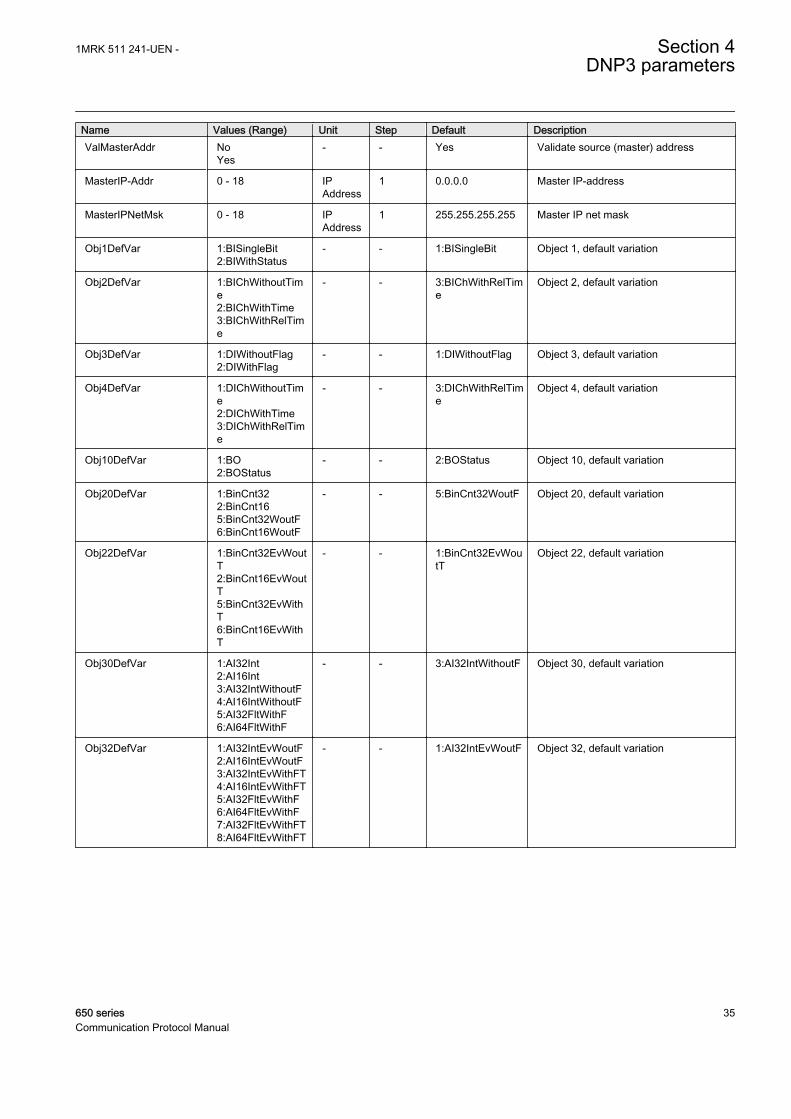
ValMasterAddr determines if the stack should validate the source address inreceive frames. DNP3 frames contain both a source address field and a destinationaddress field. If this parameter is set to 0, the stack does not validate the sourceaddress and thus the frames whose destination address matches the configuredslave session are accepted. If this parameter is set to 1, both the source and thedestination addresses have to match before the frame is accepted.
AddrQueryEnbl determines whether to enable self-address functionality on thismaster session (slave) as specified by the DNP Technical Bulletin 2003-003. Self-Address Reservation. The master session (Slave) responds to the address 0xfffc asif it had received a request for its configured address. It responds with its ownaddress so that the master can automatically discover the slave address.
ApplConfTout specifies how long the slave waits for the application layerconfirmation from the master. This in combination with unsolRetryDelay orunsolOfflineRetryDelay determines how frequently an unsolicited response is resent.
ApplMultFrgRes determines if the application layer of this master session in theslave is allowed to send multi fragment responses.
ConfMultFrag determines if application layer confirmations are requested for non-final fragments of a multi-fragment response. Application layer confirmations arealways requested for responses that contain events.
UREnable determines if unsolicited responses are allowed. If set to 0, nounsolicited responses are generated and requests to enable or disable unsolicitedresponses fail.
UREvClassMask specifies the initial or new state of the unsolicited event mask.This mask is used to determine which event class or classes generate unsolicitedresponses. According to the DNP3 specification, unsolicited responses should bedisabled until an Enable Unsolicited Response request is received from the master.Thus, this value should generally be 0. However, some masters do not generate theEnable Unsolicited Response message, in which case they must be enabled here.Keep the value to 0 for all other purposes.
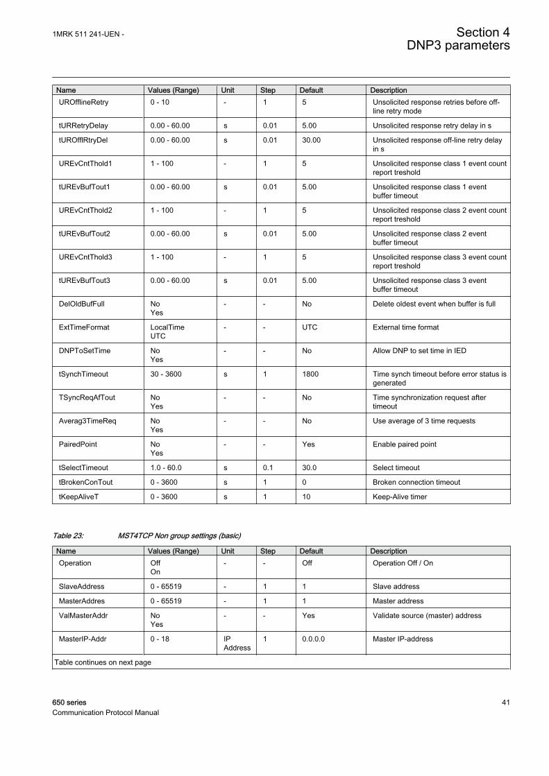
UROfflineRetry specifies the maximum number of unsolicited retries beforechanging to the offline retry period. Up to 65535 retries can be specified. SetUROfflRetryDel to the same value as URRetryDelay to define an infinite number ofretries.
tURRetryDelay specifies in seconds the time to delay after an unsolicited confirmtimeout before retrying the unsolicited response.
tUROfflRetryDel specifies in seconds the time to delay after an unsolicited timeoutbefore retrying the unsolicited response if UROfflineRetry has been attempted. Todisable retries after UROfflineRetry, set this value to the maximum value of a stacktimer: 31 days. This limits the retries to one in every 31 days.
Section 4 1MRK 511 241-UEN -DNP3 parameters
30 650 seriesCommunication Protocol Manual
UREvCntThold1 If unsolicited responses are enabled, this parameter specifies themaximum number of events in class 1 to be allowed before an unsolicited responseis generated.
tUREvBufTout1 If unsolicited responses are enabled (UREnable), this parameterspecifies the maximum amount of time in seconds before an unsolicited response isgenerated after an event in class 1 has been received.
UREvCntThold2 If unsolicited responses are enabled (UREnable), this parameterspecifies the maximum number of allowed class 2 events before an unsolicitedresponse is generated.
tUREvBufTout2 If unsolicited responses are enabled (UREnable), this parameterspecifies the maximum amount of time in seconds before an unsolicited response isgenerated after an event in class 2 has been received.
UREvCntThold3 If unsolicited responses are enabled (UREnable), this parameterspecifies the maximum number of allowed class 3 events before an unsolicitedresponse will be generated.
tUREvBufTout3 If unsolicited responses are enabled (UREnable), this parameterspecifies the maximum amount of time in seconds before an unsolicited response isgenerated after an event in class 3 has been received .
DelOldBufFull If this parameter is set to 1, the event with the earliest timeStamp isdeleted when a new event is added to the full event queue.
ExtTimeFormat 0 = LocalTime. 1 = UTC.
DNPToSetTime determines if time synch messages received for this master session(slave) are allowed to set the local time in the IED.
tSyncrhTimeout sets the periodicity for time requests. That is, it defines how longafter a succeeded time synch message from the master, the IIN.4 bit should be set.
TsyncReqAfTout determines if the stack should start with the IIN.4 bit set.
Averag3TimeReq determines if the IED needs three time synch messages to set thetime. If set, the IIN.4 bit is high until three time synch messages are received. Theaverage of the two best messages are used to set the time.
MasterIP-Addr defines the master's IP address.
MasterIPNetMsk determines the subnet mask that should be used to mask with theIP address.
The master subnet mask must not be changed unless the master getsits IP-address dynamically assigned via, for example, DHCP. Fordetails see, DNP3 TCP/IP mode
Obj1DefVar determines the default variation for Object 1, Binary Inputs.
1MRK 511 241-UEN - Section 4DNP3 parameters
650 series 31Communication Protocol Manual
Obj2DefVar determines the default variation for Object 2, Binary Input ChangeEvents.
Obj3DefVar determines the default variation for Object 3, Double Bit Inputs.
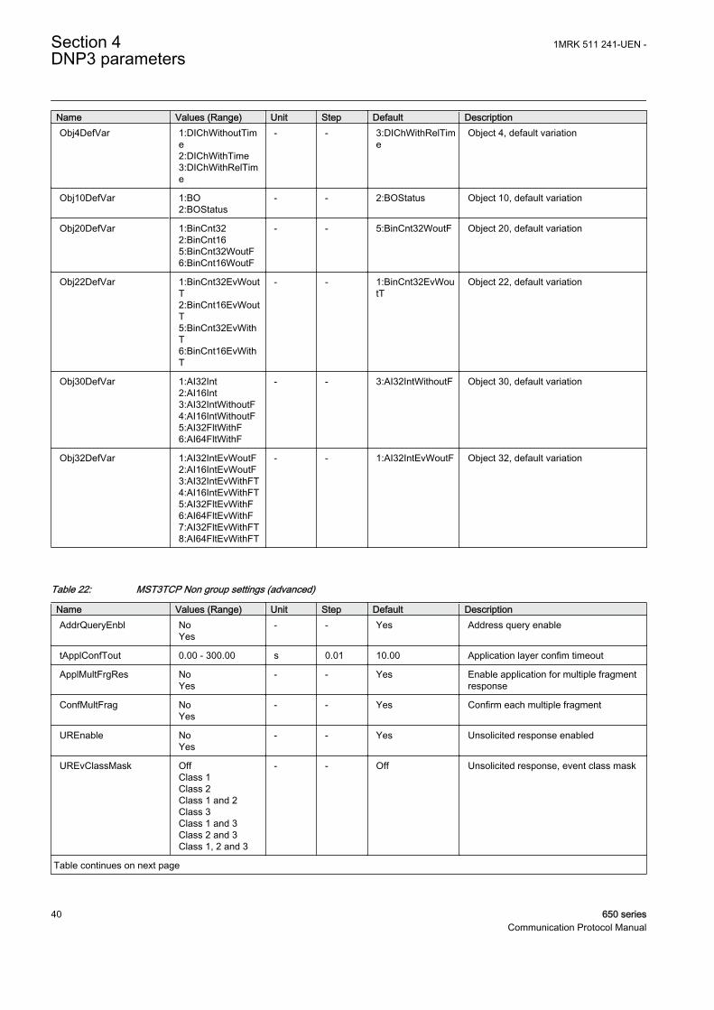
Obj4DefVar determines the default variation for Object 4, Double Bit InputChange Events.
Obj10DefVar determines the default variation for Object 10, Binary Output Status.
Obj20DefVar determines the default variation for Object 20, Binary Counters.
Obj22DefVar determines the default variation for Object 22, Binary CounterChange Events.
Obj30DefVar determines the default variation for Object 30, Analog Inputs.
Obj32DefVar determines the default variation for Object 32, Analog Change Events.
PairedPoint enables the Object12 Close request on an even-index point to accessthe next-index point.
tSelectTimeout specifies the maximum amount of time that a select remains validbefore the corresponding operate is received.
tBrokenConTout determines how long a session is active after a TCP/IP connectionhas been broken. After that time period the master session becomes inactive andevents are not stored. If the parameter is set to 0, events are stored until the buffersoverflow.
tKeepAliveT determines, in seconds, how often the DNP3 master session sends keep-alive messages. Default is 10s.
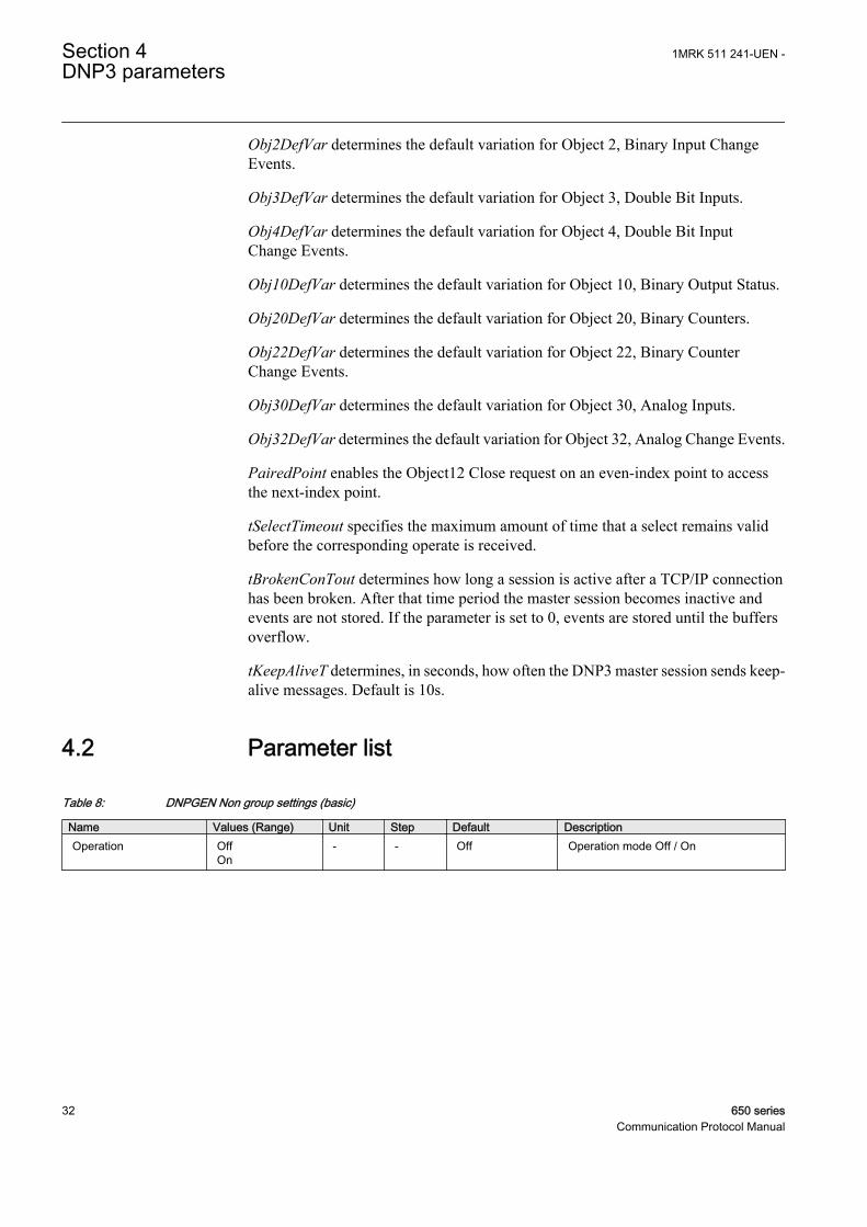
4.2 Parameter list
Table 8: DNPGEN Non group settings (basic)
Name Values (Range) Unit Step Default DescriptionOperation Off
On- - Off Operation mode Off / On
Section 4 1MRK 511 241-UEN -DNP3 parameters
32 650 seriesCommunication Protocol Manual
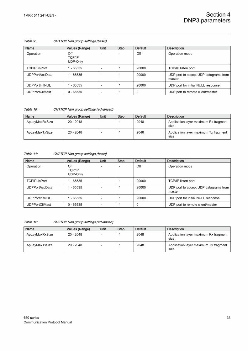
Table 9: CH1TCP Non group settings (basic)
Name Values (Range) Unit Step Default DescriptionOperation Off
TCP/IPUDP-Only
- - Off Operation mode
TCPIPLisPort 1 - 65535 - 1 20000 TCP/IP listen port
UDPPortAccData 1 - 65535 - 1 20000 UDP port to accept UDP datagrams frommaster
UDPPortInitNUL 1 - 65535 - 1 20000 UDP port for initial NULL response
UDPPortCliMast 0 - 65535 - 1 0 UDP port to remote client/master
Table 10: CH1TCP Non group settings (advanced)
Name Values (Range) Unit Step Default DescriptionApLayMaxRxSize 20 - 2048 - 1 2048 Application layer maximum Rx fragment
size
ApLayMaxTxSize 20 - 2048 - 1 2048 Application layer maximum Tx fragmentsize
Table 11: CH2TCP Non group settings (basic)
Name Values (Range) Unit Step Default DescriptionOperation Off
TCP/IPUDP-Only
- - Off Operation mode
TCPIPLisPort 1 - 65535 - 1 20000 TCP/IP listen port
UDPPortAccData 1 - 65535 - 1 20000 UDP port to accept UDP datagrams frommaster
UDPPortInitNUL 1 - 65535 - 1 20000 UDP port for initial NULL response
UDPPortCliMast 0 - 65535 - 1 0 UDP port to remote client/master
Table 12: CH2TCP Non group settings (advanced)
Name Values (Range) Unit Step Default DescriptionApLayMaxRxSize 20 - 2048 - 1 2048 Application layer maximum Rx fragment
size
ApLayMaxTxSize 20 - 2048 - 1 2048 Application layer maximum Tx fragmentsize
1MRK 511 241-UEN - Section 4DNP3 parameters
650 series 33Communication Protocol Manual
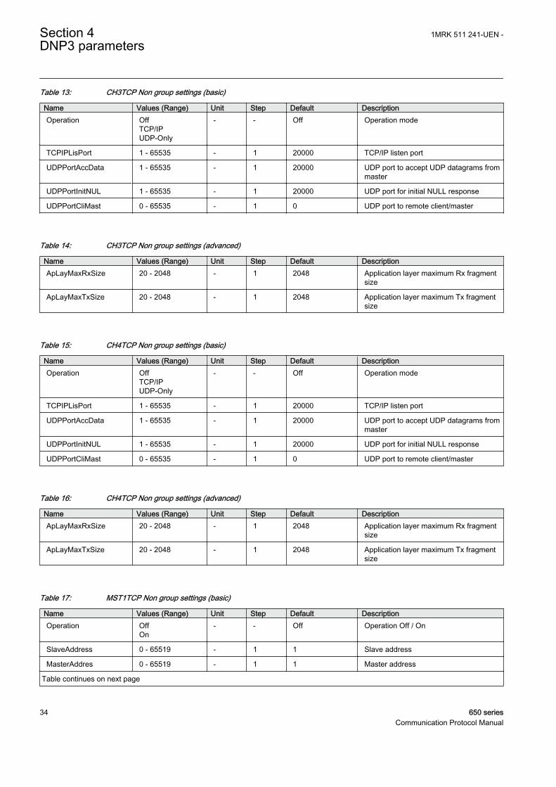
Table 13: CH3TCP Non group settings (basic)
Name Values (Range) Unit Step Default DescriptionOperation Off
TCP/IPUDP-Only
- - Off Operation mode
TCPIPLisPort 1 - 65535 - 1 20000 TCP/IP listen port
UDPPortAccData 1 - 65535 - 1 20000 UDP port to accept UDP datagrams frommaster
UDPPortInitNUL 1 - 65535 - 1 20000 UDP port for initial NULL response
UDPPortCliMast 0 - 65535 - 1 0 UDP port to remote client/master
Table 14: CH3TCP Non group settings (advanced)
Name Values (Range) Unit Step Default DescriptionApLayMaxRxSize 20 - 2048 - 1 2048 Application layer maximum Rx fragment
size
ApLayMaxTxSize 20 - 2048 - 1 2048 Application layer maximum Tx fragmentsize
Table 15: CH4TCP Non group settings (basic)
Name Values (Range) Unit Step Default DescriptionOperation Off
TCP/IPUDP-Only
- - Off Operation mode
TCPIPLisPort 1 - 65535 - 1 20000 TCP/IP listen port
UDPPortAccData 1 - 65535 - 1 20000 UDP port to accept UDP datagrams frommaster
UDPPortInitNUL 1 - 65535 - 1 20000 UDP port for initial NULL response
UDPPortCliMast 0 - 65535 - 1 0 UDP port to remote client/master
Table 16: CH4TCP Non group settings (advanced)
Name Values (Range) Unit Step Default DescriptionApLayMaxRxSize 20 - 2048 - 1 2048 Application layer maximum Rx fragment
size
ApLayMaxTxSize 20 - 2048 - 1 2048 Application layer maximum Tx fragmentsize
Table 17: MST1TCP Non group settings (basic)
Name Values (Range) Unit Step Default DescriptionOperation Off
On- - Off Operation Off / On
SlaveAddress 0 - 65519 - 1 1 Slave address
MasterAddres 0 - 65519 - 1 1 Master address
Table continues on next page
Section 4 1MRK 511 241-UEN -DNP3 parameters
34 650 seriesCommunication Protocol Manual
Name Values (Range) Unit Step Default DescriptionValMasterAddr No
Yes- - Yes Validate source (master) address
MasterIP-Addr 0 - 18 IPAddress
1 0.0.0.0 Master IP-address
MasterIPNetMsk 0 - 18 IPAddress
1 255.255.255.255 Master IP net mask
Obj1DefVar 1:BISingleBit2:BIWithStatus
- - 1:BISingleBit Object 1, default variation
Obj2DefVar 1:BIChWithoutTime2:BIChWithTime3:BIChWithRelTime
- - 3:BIChWithRelTime
Object 2, default variation
Obj3DefVar 1:DIWithoutFlag2:DIWithFlag
- - 1:DIWithoutFlag Object 3, default variation
Obj4DefVar 1:DIChWithoutTime2:DIChWithTime3:DIChWithRelTime
- - 3:DIChWithRelTime
Object 4, default variation
Obj10DefVar 1:BO2:BOStatus
- - 2:BOStatus Object 10, default variation
Obj20DefVar 1:BinCnt322:BinCnt165:BinCnt32WoutF6:BinCnt16WoutF
- - 5:BinCnt32WoutF Object 20, default variation
Obj22DefVar 1:BinCnt32EvWoutT2:BinCnt16EvWoutT5:BinCnt32EvWithT6:BinCnt16EvWithT
- - 1:BinCnt32EvWoutT
Object 22, default variation
Obj30DefVar 1:AI32Int2:AI16Int3:AI32IntWithoutF4:AI16IntWithoutF5:AI32FltWithF6:AI64FltWithF
- - 3:AI32IntWithoutF Object 30, default variation
Obj32DefVar 1:AI32IntEvWoutF2:AI16IntEvWoutF3:AI32IntEvWithFT4:AI16IntEvWithFT5:AI32FltEvWithF6:AI64FltEvWithF7:AI32FltEvWithFT8:AI64FltEvWithFT
- - 1:AI32IntEvWoutF Object 32, default variation
1MRK 511 241-UEN - Section 4DNP3 parameters
650 series 35Communication Protocol Manual
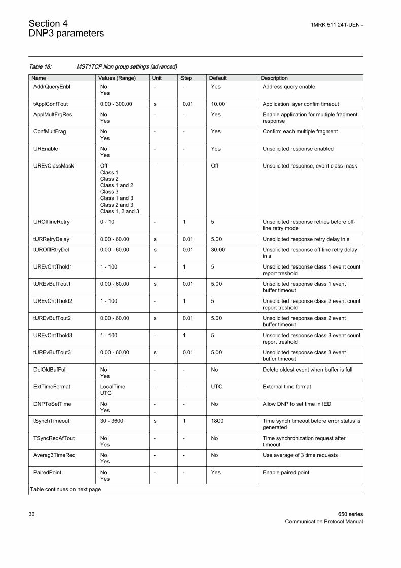
Table 18: MST1TCP Non group settings (advanced)
Name Values (Range) Unit Step Default DescriptionAddrQueryEnbl No
Yes- - Yes Address query enable
tApplConfTout 0.00 - 300.00 s 0.01 10.00 Application layer confim timeout
ApplMultFrgRes NoYes
- - Yes Enable application for multiple fragmentresponse
ConfMultFrag NoYes
- - Yes Confirm each multiple fragment
UREnable NoYes
- - Yes Unsolicited response enabled
UREvClassMask OffClass 1Class 2Class 1 and 2Class 3Class 1 and 3Class 2 and 3Class 1, 2 and 3
- - Off Unsolicited response, event class mask
UROfflineRetry 0 - 10 - 1 5 Unsolicited response retries before off-line retry mode
tURRetryDelay 0.00 - 60.00 s 0.01 5.00 Unsolicited response retry delay in s
tUROfflRtryDel 0.00 - 60.00 s 0.01 30.00 Unsolicited response off-line retry delayin s
UREvCntThold1 1 - 100 - 1 5 Unsolicited response class 1 event countreport treshold
tUREvBufTout1 0.00 - 60.00 s 0.01 5.00 Unsolicited response class 1 eventbuffer timeout
UREvCntThold2 1 - 100 - 1 5 Unsolicited response class 2 event countreport treshold
tUREvBufTout2 0.00 - 60.00 s 0.01 5.00 Unsolicited response class 2 eventbuffer timeout
UREvCntThold3 1 - 100 - 1 5 Unsolicited response class 3 event countreport treshold
tUREvBufTout3 0.00 - 60.00 s 0.01 5.00 Unsolicited response class 3 eventbuffer timeout
DelOldBufFull NoYes
- - No Delete oldest event when buffer is full
ExtTimeFormat LocalTimeUTC
- - UTC External time format
DNPToSetTime NoYes
- - No Allow DNP to set time in IED
tSynchTimeout 30 - 3600 s 1 1800 Time synch timeout before error status isgenerated
TSyncReqAfTout NoYes
- - No Time synchronization request aftertimeout
Averag3TimeReq NoYes
- - No Use average of 3 time requests
PairedPoint NoYes
- - Yes Enable paired point
Table continues on next page
Section 4 1MRK 511 241-UEN -DNP3 parameters
36 650 seriesCommunication Protocol Manual
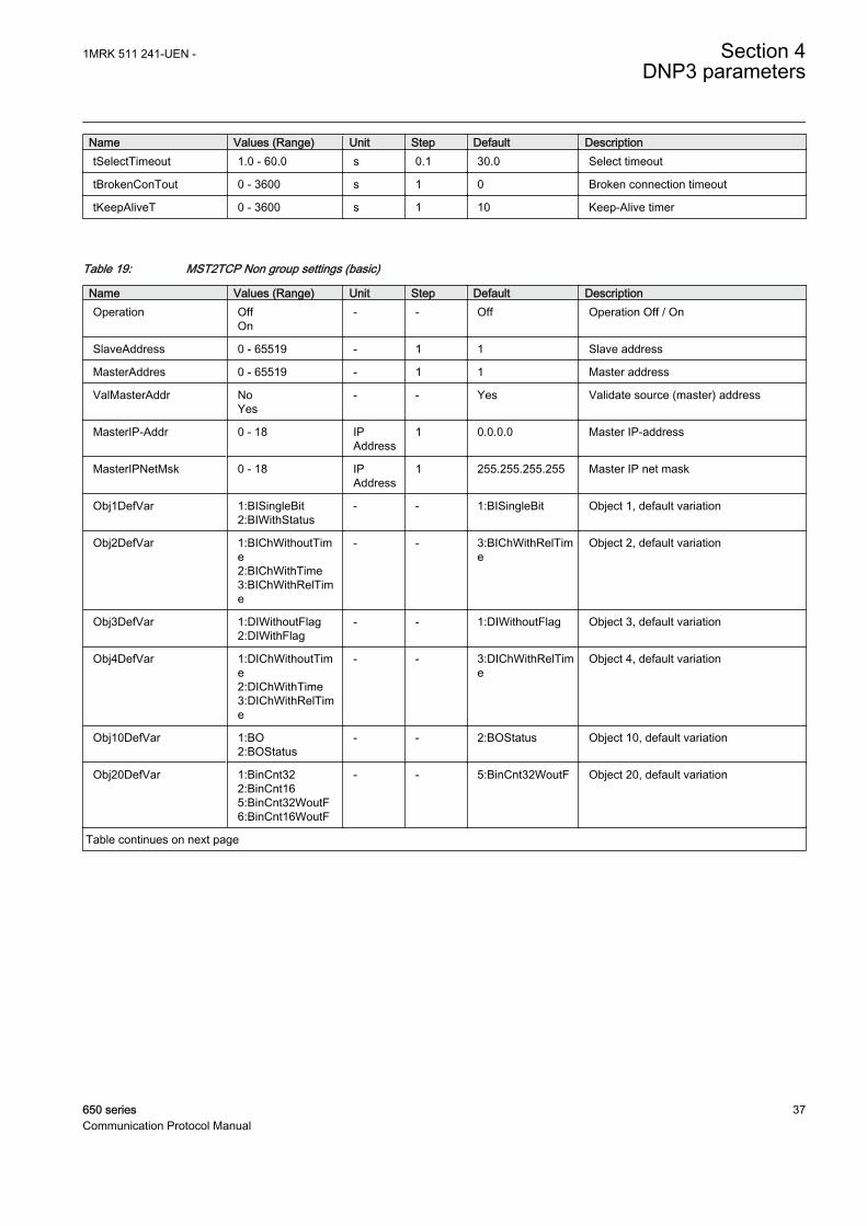
Name Values (Range) Unit Step Default DescriptiontSelectTimeout 1.0 - 60.0 s 0.1 30.0 Select timeout
tBrokenConTout 0 - 3600 s 1 0 Broken connection timeout
tKeepAliveT 0 - 3600 s 1 10 Keep-Alive timer
Table 19: MST2TCP Non group settings (basic)
Name Values (Range) Unit Step Default DescriptionOperation Off
On- - Off Operation Off / On
SlaveAddress 0 - 65519 - 1 1 Slave address
MasterAddres 0 - 65519 - 1 1 Master address
ValMasterAddr NoYes
- - Yes Validate source (master) address
MasterIP-Addr 0 - 18 IPAddress
1 0.0.0.0 Master IP-address
MasterIPNetMsk 0 - 18 IPAddress
1 255.255.255.255 Master IP net mask
Obj1DefVar 1:BISingleBit2:BIWithStatus
- - 1:BISingleBit Object 1, default variation
Obj2DefVar 1:BIChWithoutTime2:BIChWithTime3:BIChWithRelTime
- - 3:BIChWithRelTime
Object 2, default variation
Obj3DefVar 1:DIWithoutFlag2:DIWithFlag
- - 1:DIWithoutFlag Object 3, default variation
Obj4DefVar 1:DIChWithoutTime2:DIChWithTime3:DIChWithRelTime
- - 3:DIChWithRelTime
Object 4, default variation
Obj10DefVar 1:BO2:BOStatus
- - 2:BOStatus Object 10, default variation
Obj20DefVar 1:BinCnt322:BinCnt165:BinCnt32WoutF6:BinCnt16WoutF
- - 5:BinCnt32WoutF Object 20, default variation
Table continues on next page
1MRK 511 241-UEN - Section 4DNP3 parameters
650 series 37Communication Protocol Manual
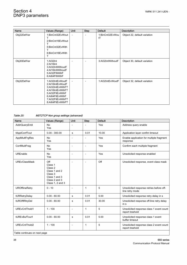
Name Values (Range) Unit Step Default DescriptionObj22DefVar 1:BinCnt32EvWout
T2:BinCnt16EvWoutT5:BinCnt32EvWithT6:BinCnt16EvWithT
- - 1:BinCnt32EvWoutT
Object 22, default variation
Obj30DefVar 1:AI32Int2:AI16Int3:AI32IntWithoutF4:AI16IntWithoutF5:AI32FltWithF6:AI64FltWithF
- - 3:AI32IntWithoutF Object 30, default variation
Obj32DefVar 1:AI32IntEvWoutF2:AI16IntEvWoutF3:AI32IntEvWithFT4:AI16IntEvWithFT5:AI32FltEvWithF6:AI64FltEvWithF7:AI32FltEvWithFT8:AI64FltEvWithFT
- - 1:AI32IntEvWoutF Object 32, default variation
Table 20: MST2TCP Non group settings (advanced)
Name Values (Range) Unit Step Default DescriptionAddrQueryEnbl No
Yes- - Yes Address query enable
tApplConfTout 0.00 - 300.00 s 0.01 10.00 Application layer confim timeout
ApplMultFrgRes NoYes
- - Yes Enable application for multiple fragmentresponse
ConfMultFrag NoYes
- - Yes Confirm each multiple fragment
UREnable NoYes
- - Yes Unsolicited response enabled
UREvClassMask OffClass 1Class 2Class 1 and 2Class 3Class 1 and 3Class 2 and 3Class 1, 2 and 3
- - Off Unsolicited response, event class mask
UROfflineRetry 0 - 10 - 1 5 Unsolicited response retries before off-line retry mode
tURRetryDelay 0.00 - 60.00 s 0.01 5.00 Unsolicited response retry delay in s
tUROfflRtryDel 0.00 - 60.00 s 0.01 30.00 Unsolicited response off-line retry delayin s
UREvCntThold1 1 - 100 - 1 5 Unsolicited response class 1 event countreport treshold
tUREvBufTout1 0.00 - 60.00 s 0.01 5.00 Unsolicited response class 1 eventbuffer timeout
UREvCntThold2 1 - 100 - 1 5 Unsolicited response class 2 event countreport treshold
Table continues on next page
Section 4 1MRK 511 241-UEN -DNP3 parameters
38 650 seriesCommunication Protocol Manual
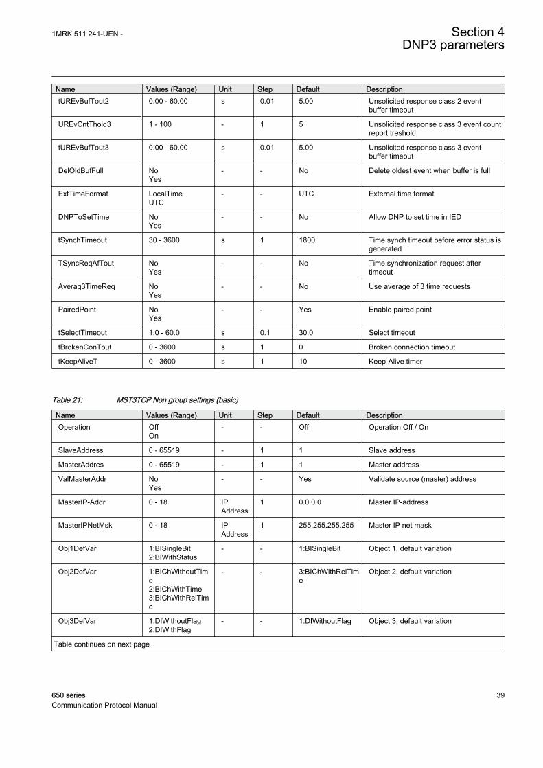
Name Values (Range) Unit Step Default DescriptiontUREvBufTout2 0.00 - 60.00 s 0.01 5.00 Unsolicited response class 2 event
buffer timeout
UREvCntThold3 1 - 100 - 1 5 Unsolicited response class 3 event countreport treshold
tUREvBufTout3 0.00 - 60.00 s 0.01 5.00 Unsolicited response class 3 eventbuffer timeout
DelOldBufFull NoYes
- - No Delete oldest event when buffer is full
ExtTimeFormat LocalTimeUTC
- - UTC External time format
DNPToSetTime NoYes
- - No Allow DNP to set time in IED
tSynchTimeout 30 - 3600 s 1 1800 Time synch timeout before error status isgenerated
TSyncReqAfTout NoYes
- - No Time synchronization request aftertimeout
Averag3TimeReq NoYes
- - No Use average of 3 time requests
PairedPoint NoYes
- - Yes Enable paired point
tSelectTimeout 1.0 - 60.0 s 0.1 30.0 Select timeout
tBrokenConTout 0 - 3600 s 1 0 Broken connection timeout
tKeepAliveT 0 - 3600 s 1 10 Keep-Alive timer
Table 21: MST3TCP Non group settings (basic)
Name Values (Range) Unit Step Default DescriptionOperation Off
On- - Off Operation Off / On
SlaveAddress 0 - 65519 - 1 1 Slave address
MasterAddres 0 - 65519 - 1 1 Master address
ValMasterAddr NoYes
- - Yes Validate source (master) address
MasterIP-Addr 0 - 18 IPAddress
1 0.0.0.0 Master IP-address
MasterIPNetMsk 0 - 18 IPAddress
1 255.255.255.255 Master IP net mask
Obj1DefVar 1:BISingleBit2:BIWithStatus
- - 1:BISingleBit Object 1, default variation
Obj2DefVar 1:BIChWithoutTime2:BIChWithTime3:BIChWithRelTime
- - 3:BIChWithRelTime
Object 2, default variation
Obj3DefVar 1:DIWithoutFlag2:DIWithFlag
- - 1:DIWithoutFlag Object 3, default variation
Table continues on next page
1MRK 511 241-UEN - Section 4DNP3 parameters
650 series 39Communication Protocol Manual
Name Values (Range) Unit Step Default DescriptionObj4DefVar 1:DIChWithoutTim
e2:DIChWithTime3:DIChWithRelTime
- - 3:DIChWithRelTime
Object 4, default variation
Obj10DefVar 1:BO2:BOStatus
- - 2:BOStatus Object 10, default variation
Obj20DefVar 1:BinCnt322:BinCnt165:BinCnt32WoutF6:BinCnt16WoutF
- - 5:BinCnt32WoutF Object 20, default variation
Obj22DefVar 1:BinCnt32EvWoutT2:BinCnt16EvWoutT5:BinCnt32EvWithT6:BinCnt16EvWithT
- - 1:BinCnt32EvWoutT
Object 22, default variation
Obj30DefVar 1:AI32Int2:AI16Int3:AI32IntWithoutF4:AI16IntWithoutF5:AI32FltWithF6:AI64FltWithF
- - 3:AI32IntWithoutF Object 30, default variation
Obj32DefVar 1:AI32IntEvWoutF2:AI16IntEvWoutF3:AI32IntEvWithFT4:AI16IntEvWithFT5:AI32FltEvWithF6:AI64FltEvWithF7:AI32FltEvWithFT8:AI64FltEvWithFT
- - 1:AI32IntEvWoutF Object 32, default variation
Table 22: MST3TCP Non group settings (advanced)
Name Values (Range) Unit Step Default DescriptionAddrQueryEnbl No
Yes- - Yes Address query enable
tApplConfTout 0.00 - 300.00 s 0.01 10.00 Application layer confim timeout
ApplMultFrgRes NoYes
- - Yes Enable application for multiple fragmentresponse
ConfMultFrag NoYes
- - Yes Confirm each multiple fragment
UREnable NoYes
- - Yes Unsolicited response enabled
UREvClassMask OffClass 1Class 2Class 1 and 2Class 3Class 1 and 3Class 2 and 3Class 1, 2 and 3
- - Off Unsolicited response, event class mask
Table continues on next page
Section 4 1MRK 511 241-UEN -DNP3 parameters
40 650 seriesCommunication Protocol Manual
Name Values (Range) Unit Step Default DescriptionUROfflineRetry 0 - 10 - 1 5 Unsolicited response retries before off-
line retry mode
tURRetryDelay 0.00 - 60.00 s 0.01 5.00 Unsolicited response retry delay in s
tUROfflRtryDel 0.00 - 60.00 s 0.01 30.00 Unsolicited response off-line retry delayin s
UREvCntThold1 1 - 100 - 1 5 Unsolicited response class 1 event countreport treshold
tUREvBufTout1 0.00 - 60.00 s 0.01 5.00 Unsolicited response class 1 eventbuffer timeout
UREvCntThold2 1 - 100 - 1 5 Unsolicited response class 2 event countreport treshold
tUREvBufTout2 0.00 - 60.00 s 0.01 5.00 Unsolicited response class 2 eventbuffer timeout
UREvCntThold3 1 - 100 - 1 5 Unsolicited response class 3 event countreport treshold
tUREvBufTout3 0.00 - 60.00 s 0.01 5.00 Unsolicited response class 3 eventbuffer timeout
DelOldBufFull NoYes
- - No Delete oldest event when buffer is full
ExtTimeFormat LocalTimeUTC
- - UTC External time format
DNPToSetTime NoYes
- - No Allow DNP to set time in IED
tSynchTimeout 30 - 3600 s 1 1800 Time synch timeout before error status isgenerated
TSyncReqAfTout NoYes
- - No Time synchronization request aftertimeout
Averag3TimeReq NoYes
- - No Use average of 3 time requests
PairedPoint NoYes
- - Yes Enable paired point
tSelectTimeout 1.0 - 60.0 s 0.1 30.0 Select timeout
tBrokenConTout 0 - 3600 s 1 0 Broken connection timeout
tKeepAliveT 0 - 3600 s 1 10 Keep-Alive timer
Table 23: MST4TCP Non group settings (basic)
Name Values (Range) Unit Step Default DescriptionOperation Off
On- - Off Operation Off / On
SlaveAddress 0 - 65519 - 1 1 Slave address
MasterAddres 0 - 65519 - 1 1 Master address
ValMasterAddr NoYes
- - Yes Validate source (master) address
MasterIP-Addr 0 - 18 IPAddress
1 0.0.0.0 Master IP-address
Table continues on next page
1MRK 511 241-UEN - Section 4DNP3 parameters
650 series 41Communication Protocol Manual
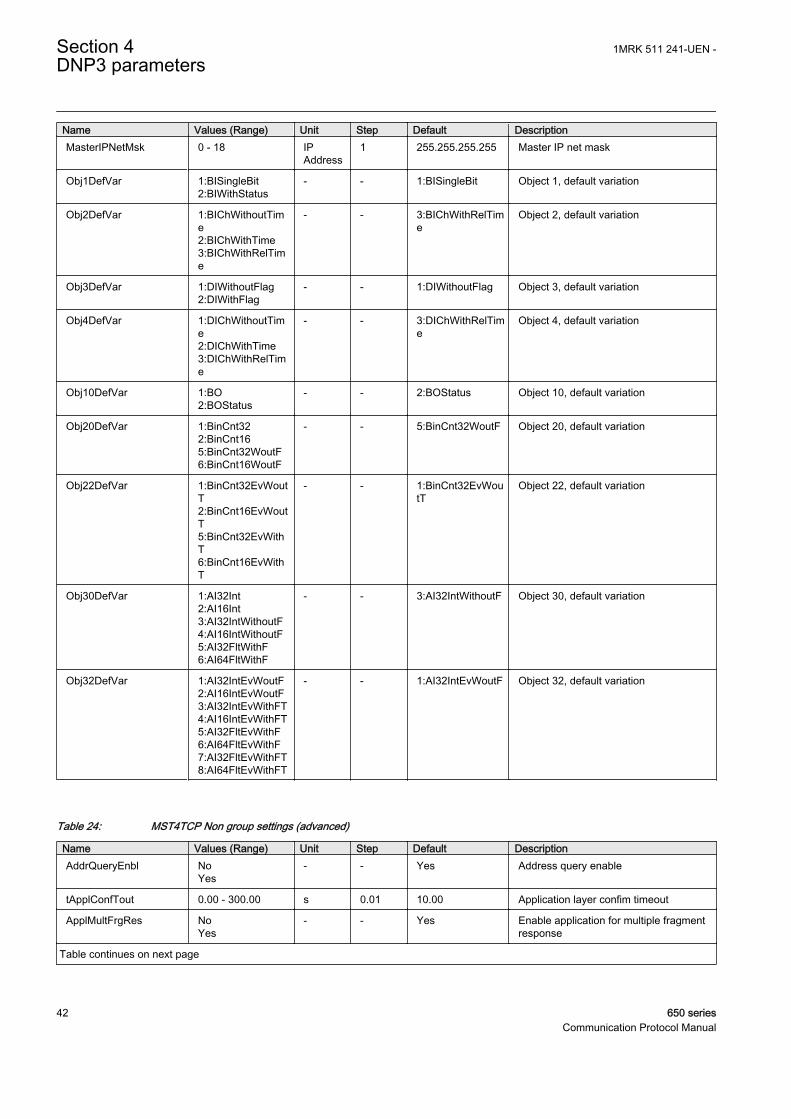
Name Values (Range) Unit Step Default DescriptionMasterIPNetMsk 0 - 18 IP
Address1 255.255.255.255 Master IP net mask
Obj1DefVar 1:BISingleBit2:BIWithStatus
- - 1:BISingleBit Object 1, default variation
Obj2DefVar 1:BIChWithoutTime2:BIChWithTime3:BIChWithRelTime
- - 3:BIChWithRelTime
Object 2, default variation
Obj3DefVar 1:DIWithoutFlag2:DIWithFlag
- - 1:DIWithoutFlag Object 3, default variation
Obj4DefVar 1:DIChWithoutTime2:DIChWithTime3:DIChWithRelTime
- - 3:DIChWithRelTime
Object 4, default variation
Obj10DefVar 1:BO2:BOStatus
- - 2:BOStatus Object 10, default variation
Obj20DefVar 1:BinCnt322:BinCnt165:BinCnt32WoutF6:BinCnt16WoutF
- - 5:BinCnt32WoutF Object 20, default variation
Obj22DefVar 1:BinCnt32EvWoutT2:BinCnt16EvWoutT5:BinCnt32EvWithT6:BinCnt16EvWithT
- - 1:BinCnt32EvWoutT
Object 22, default variation
Obj30DefVar 1:AI32Int2:AI16Int3:AI32IntWithoutF4:AI16IntWithoutF5:AI32FltWithF6:AI64FltWithF
- - 3:AI32IntWithoutF Object 30, default variation
Obj32DefVar 1:AI32IntEvWoutF2:AI16IntEvWoutF3:AI32IntEvWithFT4:AI16IntEvWithFT5:AI32FltEvWithF6:AI64FltEvWithF7:AI32FltEvWithFT8:AI64FltEvWithFT
- - 1:AI32IntEvWoutF Object 32, default variation
Table 24: MST4TCP Non group settings (advanced)
Name Values (Range) Unit Step Default DescriptionAddrQueryEnbl No
Yes- - Yes Address query enable
tApplConfTout 0.00 - 300.00 s 0.01 10.00 Application layer confim timeout
ApplMultFrgRes NoYes
- - Yes Enable application for multiple fragmentresponse
Table continues on next page
Section 4 1MRK 511 241-UEN -DNP3 parameters
42 650 seriesCommunication Protocol Manual
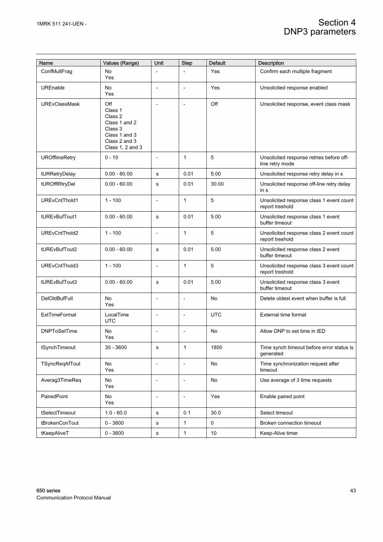
Name Values (Range) Unit Step Default DescriptionConfMultFrag No
Yes- - Yes Confirm each multiple fragment
UREnable NoYes
- - Yes Unsolicited response enabled
UREvClassMask OffClass 1Class 2Class 1 and 2Class 3Class 1 and 3Class 2 and 3Class 1, 2 and 3
- - Off Unsolicited response, event class mask
UROfflineRetry 0 - 10 - 1 5 Unsolicited response retries before off-line retry mode
tURRetryDelay 0.00 - 60.00 s 0.01 5.00 Unsolicited response retry delay in s
tUROfflRtryDel 0.00 - 60.00 s 0.01 30.00 Unsolicited response off-line retry delayin s
UREvCntThold1 1 - 100 - 1 5 Unsolicited response class 1 event countreport treshold
tUREvBufTout1 0.00 - 60.00 s 0.01 5.00 Unsolicited response class 1 eventbuffer timeout
UREvCntThold2 1 - 100 - 1 5 Unsolicited response class 2 event countreport treshold
tUREvBufTout2 0.00 - 60.00 s 0.01 5.00 Unsolicited response class 2 eventbuffer timeout
UREvCntThold3 1 - 100 - 1 5 Unsolicited response class 3 event countreport treshold
tUREvBufTout3 0.00 - 60.00 s 0.01 5.00 Unsolicited response class 3 eventbuffer timeout
DelOldBufFull NoYes
- - No Delete oldest event when buffer is full
ExtTimeFormat LocalTimeUTC
- - UTC External time format
DNPToSetTime NoYes
- - No Allow DNP to set time in IED
tSynchTimeout 30 - 3600 s 1 1800 Time synch timeout before error status isgenerated
TSyncReqAfTout NoYes
- - No Time synchronization request aftertimeout
Averag3TimeReq NoYes
- - No Use average of 3 time requests
PairedPoint NoYes
- - Yes Enable paired point
tSelectTimeout 1.0 - 60.0 s 0.1 30.0 Select timeout
tBrokenConTout 0 - 3600 s 1 0 Broken connection timeout
tKeepAliveT 0 - 3600 s 1 10 Keep-Alive timer
1MRK 511 241-UEN - Section 4DNP3 parameters
650 series 43Communication Protocol Manual

44
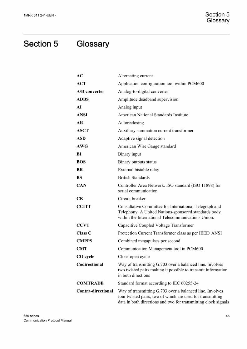
Section 5 Glossary
AC Alternating current
ACT Application configuration tool within PCM600
A/D converter Analog-to-digital converter
ADBS Amplitude deadband supervision
AI Analog input
ANSI American National Standards Institute
AR Autoreclosing
ASCT Auxiliary summation current transformer
ASD Adaptive signal detection
AWG American Wire Gauge standard
BI Binary input
BOS Binary outputs status
BR External bistable relay
BS British Standards
CAN Controller Area Network. ISO standard (ISO 11898) forserial communication
CB Circuit breaker
CCITT Consultative Committee for International Telegraph andTelephony. A United Nations-sponsored standards bodywithin the International Telecommunications Union.
CCVT Capacitive Coupled Voltage Transformer
Class C Protection Current Transformer class as per IEEE/ ANSI
CMPPS Combined megapulses per second
CMT Communication Management tool in PCM600
CO cycle Close-open cycle
Codirectional Way of transmitting G.703 over a balanced line. Involvestwo twisted pairs making it possible to transmit informationin both directions
COMTRADE Standard format according to IEC 60255-24
Contra-directional Way of transmitting G.703 over a balanced line. Involvesfour twisted pairs, two of which are used for transmittingdata in both directions and two for transmitting clock signals
1MRK 511 241-UEN - Section 5Glossary
650 series 45Communication Protocol Manual
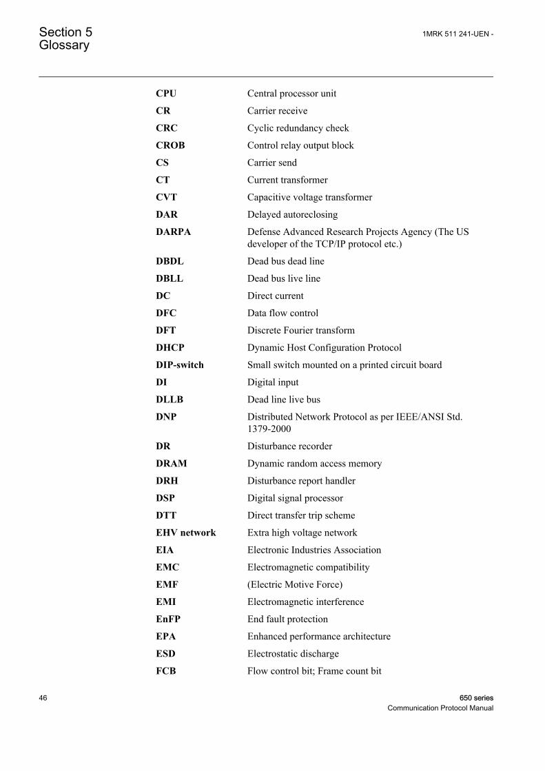
CPU Central processor unit
CR Carrier receive
CRC Cyclic redundancy check
CROB Control relay output block
CS Carrier send
CT Current transformer
CVT Capacitive voltage transformer
DAR Delayed autoreclosing
DARPA Defense Advanced Research Projects Agency (The USdeveloper of the TCP/IP protocol etc.)
DBDL Dead bus dead line
DBLL Dead bus live line
DC Direct current
DFC Data flow control
DFT Discrete Fourier transform
DHCP Dynamic Host Configuration Protocol
DIP-switch Small switch mounted on a printed circuit board
DI Digital input
DLLB Dead line live bus
DNP Distributed Network Protocol as per IEEE/ANSI Std.1379-2000
DR Disturbance recorder
DRAM Dynamic random access memory
DRH Disturbance report handler
DSP Digital signal processor
DTT Direct transfer trip scheme
EHV network Extra high voltage network
EIA Electronic Industries Association
EMC Electromagnetic compatibility
EMF (Electric Motive Force)
EMI Electromagnetic interference
EnFP End fault protection
EPA Enhanced performance architecture
ESD Electrostatic discharge
FCB Flow control bit; Frame count bit
Section 5 1MRK 511 241-UEN -Glossary
46 650 seriesCommunication Protocol Manual
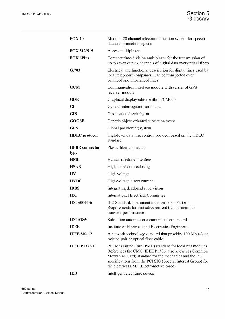
FOX 20 Modular 20 channel telecommunication system for speech,data and protection signals
FOX 512/515 Access multiplexer
FOX 6Plus Compact time-division multiplexer for the transmission ofup to seven duplex channels of digital data over optical fibers
G.703 Electrical and functional description for digital lines used bylocal telephone companies. Can be transported overbalanced and unbalanced lines
GCM Communication interface module with carrier of GPSreceiver module
GDE Graphical display editor within PCM600
GI General interrogation command
GIS Gas-insulated switchgear
GOOSE Generic object-oriented substation event
GPS Global positioning system
HDLC protocol High-level data link control, protocol based on the HDLCstandard
HFBR connectortype
Plastic fiber connector
HMI Human-machine interface
HSAR High speed autoreclosing
HV High-voltage
HVDC High-voltage direct current
IDBS Integrating deadband supervision
IEC International Electrical Committee
IEC 60044-6 IEC Standard, Instrument transformers – Part 6:Requirements for protective current transformers fortransient performance
IEC 61850 Substation automation communication standard
IEEE Institute of Electrical and Electronics Engineers
IEEE 802.12 A network technology standard that provides 100 Mbits/s ontwisted-pair or optical fiber cable
IEEE P1386.1 PCI Mezzanine Card (PMC) standard for local bus modules.References the CMC (IEEE P1386, also known as CommonMezzanine Card) standard for the mechanics and the PCIspecifications from the PCI SIG (Special Interest Group) forthe electrical EMF (Electromotive force).
IED Intelligent electronic device
1MRK 511 241-UEN - Section 5Glossary
650 series 47Communication Protocol Manual
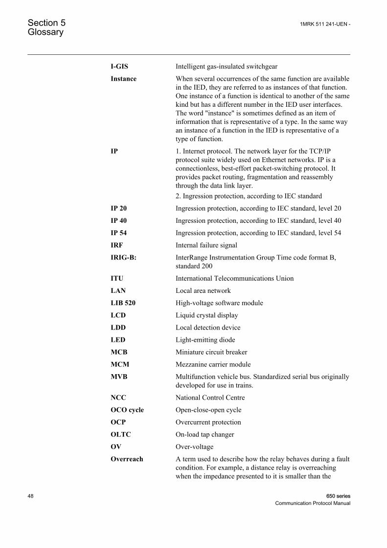
I-GIS Intelligent gas-insulated switchgear
Instance When several occurrences of the same function are availablein the IED, they are referred to as instances of that function.One instance of a function is identical to another of the samekind but has a different number in the IED user interfaces.The word "instance" is sometimes defined as an item ofinformation that is representative of a type. In the same wayan instance of a function in the IED is representative of atype of function.
IP 1. Internet protocol. The network layer for the TCP/IPprotocol suite widely used on Ethernet networks. IP is aconnectionless, best-effort packet-switching protocol. Itprovides packet routing, fragmentation and reassemblythrough the data link layer.2. Ingression protection, according to IEC standard
IP 20 Ingression protection, according to IEC standard, level 20
IP 40 Ingression protection, according to IEC standard, level 40
IP 54 Ingression protection, according to IEC standard, level 54
IRF Internal failure signal
IRIG-B: InterRange Instrumentation Group Time code format B,standard 200
ITU International Telecommunications Union
LAN Local area network
LIB 520 High-voltage software module
LCD Liquid crystal display
LDD Local detection device
LED Light-emitting diode
MCB Miniature circuit breaker
MCM Mezzanine carrier module
MVB Multifunction vehicle bus. Standardized serial bus originallydeveloped for use in trains.
NCC National Control Centre
OCO cycle Open-close-open cycle
OCP Overcurrent protection
OLTC On-load tap changer
OV Over-voltage
Overreach A term used to describe how the relay behaves during a faultcondition. For example, a distance relay is overreachingwhen the impedance presented to it is smaller than the
Section 5 1MRK 511 241-UEN -Glossary
48 650 seriesCommunication Protocol Manual
apparent impedance to the fault applied to the balance point,that is, the set reach. The relay “sees” the fault but perhaps itshould not have seen it.
PCI Peripheral component interconnect, a local data bus
PCM Pulse code modulation
PCM600 Protection and control IED manager
PC-MIP Mezzanine card standard
PISA Process interface for sensors & actuators
PMC PCI Mezzanine card
POR Permissive overreach
POTT Permissive overreach transfer trip
Process bus Bus or LAN used at the process level, that is, in nearproximity to the measured and/or controlled components
PSM Power supply module
PST Parameter setting tool within PCM600
PT ratio Potential transformer or voltage transformer ratio
PUTT Permissive underreach transfer trip
RASC Synchrocheck relay, COMBIFLEX
RCA Relay characteristic angle
RFPP Resistance for phase-to-phase faults
RFPE Resistance for phase-to-earth faults
RISC Reduced instruction set computer
RMS value Root mean square value
RS422 A balanced serial interface for the transmission of digitaldata in point-to-point connections
RS485 Serial link according to EIA standard RS485
RTC Real-time clock
RTU Remote terminal unit
SA Substation Automation
SBO Select-before-operate
SC Switch or push button to close
SCS Station control system
SCADA Supervision, control and data acquisition
SCT System configuration tool according to standard IEC 61850
SDU Service data unit
1MRK 511 241-UEN - Section 5Glossary
650 series 49Communication Protocol Manual
SMA connector Subminiature version A, A threaded connector with constantimpedance.
SMT Signal matrix tool within PCM600
SMS Station monitoring system
SNTP Simple network time protocol – is used to synchronizecomputer clocks on local area networks. This reduces therequirement to have accurate hardware clocks in everyembedded system in a network. Each embedded node caninstead synchronize with a remote clock, providing therequired accuracy.
SRY Switch for CB ready condition
ST Switch or push button to trip
Starpoint Neutral point of transformer or generator
SVC Static VAr compensation
TC Trip coil
TCS Trip circuit supervision
TCP Transmission control protocol. The most common transportlayer protocol used on Ethernet and the Internet.
TCP/IP Transmission control protocol over Internet Protocol. The defacto standard Ethernet protocols incorporated into 4.2BSDUnix. TCP/IP was developed by DARPA for Internetworking and encompasses both network layer and transportlayer protocols. While TCP and IP specify two protocols atspecific protocol layers, TCP/IP is often used to refer to theentire US Department of Defense protocol suite based uponthese, including Telnet, FTP, UDP and RDP.
TNC connector Threaded Neill-Concelman, a threaded constant impedanceversion of a BNC connector
TPZ, TPY, TPX,TPS
Current transformer class according to IEC
UMT User management tool
Underreach A term used to describe how the relay behaves during a faultcondition. For example, a distance relay is underreachingwhen the impedance presented to it is greater than theapparent impedance to the fault applied to the balance point,that is, the set reach. The relay does not “see” the fault butperhaps it should have seen it. See also Overreach.
U/I-PISA Process interface components that deliver measured voltageand current values
UTC Coordinated Universal Time. A coordinated time scale,maintained by the Bureau International des Poids et Mesures(BIPM), which forms the basis of a coordinated
Section 5 1MRK 511 241-UEN -Glossary
50 650 seriesCommunication Protocol Manual
dissemination of standard frequencies and time signals. UTCis derived from International Atomic Time (TAI) by theaddition of a whole number of "leap seconds" to synchronizeit with Universal Time 1 (UT1), thus allowing for theeccentricity of the Earth's orbit, the rotational axis tilt (23.5degrees), but still showing the Earth's irregular rotation, onwhich UT1 is based. The Coordinated Universal Time isexpressed using a 24-hour clock, and uses the Gregoriancalendar. It is used for aeroplane and ship navigation, whereit is also sometimes known by the military name, "Zulutime." "Zulu" in the phonetic alphabet stands for "Z", whichstands for longitude zero.
UV Undervoltage
WEI Weak end infeed logic
VT Voltage transformer
X.21 A digital signalling interface primarily used for telecomequipment
3IO Three times zero-sequence current. Often referred to as theresidual or the earth-fault current
3UO Three times the zero sequence voltage. Often referred to asthe residual voltage or the neutral point voltage
1MRK 511 241-UEN - Section 5Glossary
650 series 51Communication Protocol Manual

52

53

Contact us
ABB ABSubstation Automation ProductsSE-721 59 Västerås, SwedenPhone +46 (0) 21 32 50 00Fax +46 (0) 21 14 69 18
www.abb.com/substationautomation
1MR
K 5
11 2
41-U
EN
-©
Cop
yrig
ht 2
011
AB
B. A
ll rig
hts
rese
rved
.