@DNOVA - THN Application guide
24
Providing indoor climate comfort @DNOVA - THN Application guide @DNOVA-THN-AGU-0907-E
Transcript of @DNOVA - THN Application guide

Providing indoor climate comfort
@DNOVA - THN
Application guide
@DNOVA-THN-AGU-0907-E


Application Guide @DNOVA-THN-0907-E - Page �
THN = Design & Technology
Features and Benefits
Configuration DIGIT
Manufacturing Specifications
Control Software and Hardware
List of Main Options
Tests and Reference Standards
Technical Data
Dimensional Drawings
Refrigerant Circuit
Index
IndexAGUTHN
Our products comply with the European standards.
Due to LENNOX ongoing commitment to quality, specifications subject to change without notice and without incurring liability.
LENNOX have been providing environmental solutions since 1985, our range of @DNOVA continues to meet the standards that have made LENNOX a household name. Flexible design solutions to meet YOUR needs and uncompromising attention to detail. Engineering to last, simple to maintain and Quality that comes as standard.Information on local contacts at www.lennoxeurope.com.
All the technical and techological information contained in this manual, including any drawing and technical descritptions provided by us, remain the property of LENNOX and must not be utilised (except in the operation of this product), reproducted, issued or made available to third parties without the prior written agreement of LENNOX.

Page � - Application Guide @DNOVA-THN-0907-E
THN = Design & Technology
THN = Design & Technology
THN unitsThe units of the series THN "LENNOX Telecom packaged air conditioning units for indoor applications" are to be used for the conditioning of low and medium powered telephone exchanges.
They are designed to be mounted inside shelter.
VersionsThanks to the innovative design and the original solutions, THN can be easly used in the most different configurations of the des-tination site. It is available in the following versions:• THN*D version:- Air delivery Downwards;•THN*U version:- Air delivery Upwards.
Indoor mountingThe machines are designed for an indoor mounting with Plug & Play logic, to reduce the installation times and the need of specific professional skills in the installation step.
Direct expansionThe THN package units are mono-block conditioners with direct expansion and air-cooled condenser. The innovative system of air circulation gives a significant improvement of the performances in different thermal load conditions.
Reduced noise levelThe use of centrifugal fans with 4-pole backward curved blades, together with a Scroll-type compressor and a cabinet design eliminating every source of inner sound reflection and vibrations, makes this equipment suitable also for city areas.
Minimized pressure dropThewhole recirculating and Free-Cooling section has been designed to limit the pressure drop (air side) and to maxi-mize the unit performance; for this reason, the THN units are featured by the exclusive equipment with backward curved blade centrifugal fans (Plug fans), the wide surfaces of the evaporating coils and of the intake grilles, in line with the supply standard of the main phone companies.
StructureAll THN units supporting structure are made of thick galvanized sheet steel, and enclosing panels made galvanised sheer steel coated with epoxy polyester powder paint oven cured at 180 °C (RAL xxxx). It is featured by rounded shape edges, according to innovative style trends and the accid ent prevention. All structure details are entirely produced in-house with automatic proces-ses integrating the CAD-3D designing (solid modeller) with the production process (CAM) = CAD-CAM.
The unit features an exclusive design which, combined with a rational layout of components and extremely compact dimen-sions, lends it an attractive appearance.
PanellingThe front panels are equipped with handles for an easy removal for inspections. Theunit maintenance can be fully made from the front, including the innovative extractable damper section. This enables a unique flexibility, with unit "On Site Upgrading" and the possibility to access and clean the condensate collecting tray.
Power suppliesAll units are available with different supply voltages, with the option of double power supply. In this case it is possible to have a 48 VDC solution for the air-conditioning control, even in case of power failure.
European directivesThe THN units are designed and manufactured according to the European directives currently in force, and are consequently marked CE.
THN*DFRONT VIEW
THN*UFRONT VIEW

Application Guide @DNOVA-THN-0907-E - Page �
Features and Benefits
Features and Benefits
Design & TechnologyThe THN units introduce a new plant model featured by a pleasant design matched with a rational arrangement of the components and an excellent assembly compactness.
All units are factory tested by using automatic systems based on objective "in-out" criteria and are ready to be installed and started by simple wiring on site.
InstallationThe THN package air-conditioning unit is suitable for all envi-ronments exept aggressive ones. Make sure that the air inlet grilles have more than 0,8 m free space around. Do not place any obstacles near the unit and make sure that the air flow is not impeded by obstacles and/or situarions causing back suction (seeFig.1).
The recommended sizes for the power cables and emergency line are shown in Tab.1.
HandlingWhile the unit is being unloaded and positioned, utmost care must be taken to avoid abrupt or violent manoeuvres. The unit must be handled carefully and gently; avoid using machine components as anchorages or holds and always keep it in an upright position. The unit should be lifted using the pallet it is packed on; a transpallet or similar conveyance means should be used.
Start-up
Preliminary checks• Check that the electrical connections have been made properly
and that all the terminals are securely tightened. This check should also be included in a periodic six-month inspection.
• Check that the voltage at the RST terminals is 400V + 5% and make sure the yellow indicator light of the phase sequence relay is on. The phase sequence relay is positio-ned on the electric control board; if the sequence is not duly observed, it will not enable the machine to start.
• Make sure there are no refrigerant leaks that may have been caused by”accid ental impacts during transport and/or instal-lation.
• Check the power supply to the crankcase heating elements (if present).
First time startingAttention:
The unit is filled with HFC R407C refrigerant. This refrigerant belongs to group I (no toxic-no dangerous) according to EN Norm 378 and according the specification contained into CEE law n5 2037/00.
• Install the unit in the computer room.• Connect the power supply and the earth connection to the
main switch and to the main earth connection.
The starting procedure is operated by pressing the key "ON" on the control keyboard.
Noise levelsThe THN units include the exclusive use of ventilation so-lutions, featured by a low emitted noise level making these conditioners compatible with city installations.The sup-port structure, the panels and the fastening systems are designed to reduce vibrations and their transmission as low frequency sound emissions as much as possible.
Energy efficiencyThe highest possible energy efficiency has been the main tar-get in the whole thermo-dynamic and aeraulic designing. The refrigerating circuit is featured by the use of "rolling piston" or "Scroll" compressors with top reliability and (optional) possibility of replacing the traditional with an electronically - controlled electric valve: this brings a reduced energy consumption by 50%”when the outer temperature lowers below 20°C and, above all, when the direct free-cooling is not possible.The aeraulic”circuit implies the use of centrifugal fans with bac-kward curved blades, featured by a very high reaction degree, it is thus possible to remove the scroll and the relevant energy losses in the dynamic-statical conversion; all used fans can be equipped with "brushless" motor with permanent magnets and relevant switching electronics, that can be directly powered by an emergency mains at 48VDC or 24VDC. In this case, the dc motor efficiency matches with the fan efficiency, thus reaching outstanding energy results (over 45%).
The Freecooling in simultaneous operation contributes remarkably to reduce energy costs in the range of outer temperatures between the inner set point and TFT (Total Free-Cooling temperature).
Emergency situations
All units can be equipped with dual supply: main supply and "DC" supply.
• Main supply: - Compressor - Heating - Condensing section fan
• 24VDC or 48VDC supply: - Evaporating section fan - Microprocessor
- Damper servomotor
In case of mains failure, a voltage presence relay signals this to the "mP" control that, together with the ventilation and Free-Cooling section, continues to be powered by back-up batteries. This ensures the air-conditioning control even with possible inner temperature variations from the set-point values.
Manufacturing featuresAll electric, aeraulic and refrigerating components are assembled inside the machine cabinet and cannot be accessed from outside, without removing the panels. The machine has a min. protection degree IP 44 and the protection grilles of the rotary parts comply with the accid ent prevention section of the norms EN 60335; as option, a further protecting grille for the condensing section fan front is available.

Page � - Application Guide @DNOVA-THN-0907-E
FEATURES AND Benefits
UpgradingThe THN series is developed on three dimensional "frames" This enables the upgrading of the basic radio stations due to the implementation of new transmission standards, and therefore to the increased inner thermal load.
Fig. 1 - Service Area (top view)
Out
door
Indo
or
200mm
3000
mm
1000
mm
UN
IT
UNITTab.1
- Cables Sizes
UNIT MODEL MAINS POWER SUPPLY CABLE TYPE UPS EMERGENCY LINE CABLE TYPE
THN 045 THN 056 230V / 1Ph / 50Hz 2x6mm2 +Tx6mm2 48VDC / 230VAC 2 x 2,5mm2
THN 073
THN 090 THN 105 THN 120 400V / 3Ph + N / 50Hz 4x6mm2 +Tx6mm2 48VDC / 230VAC 2 x 4,0mm2
THN 150 THN 170

Application Guide @DNOVA-THN-0907-E - Page �
Configuration DIGIT
Configuration DIGIT
The numerous constructive options may be selected using the configuration scheme illustrated bellow.
T H N U 0 4 5 1 1 2 3 4 5 6 7 8 9 10 11 12
Family:LENNOX Telecom unitD Version: Air delivery downwardsU Version: Air delivery upwards
•
•
Refrigerating capacity "kW x 10"
No of refrigerant circuits
C o n f i g u r a t i o n DIGIT
1 Supply (+ auxiliary) 0 230V / 1 Ph / 50 Hz1 230V / 1 Ph / 50 Hz + [24VDC]2 230V / 1 Ph / 50 Hz + [48VDC]3 230V / 1 Ph / 50 Hz + [230V / 1 Ph / 50 Hz]4 400V / 3 Ph + N / 50 Hz5 400V / 3 Ph + N / 50 Hz + [24VDC]6 400V / 3 Ph + N / 50 Hz + [48VDC]7 400V / 3 Ph + N / 50 Hz + [230V / 1 Ph / 50 Hz]
2 Control 0 BASICB ADVANCED [with local user interface]D ADVANCED [without local user interface]
3 Refrigerating cycle options 0 R407C1 R407C + electronic thermal expansion valve2 R223 R22 + electronic thermal expansion valve
4 Cabinet options E Painted galvanized sheet metal RAL7035
5 Electric re-heating 0 Heaters - NO1 Heaters - YES
6 Free-cooling 0 Without Free-coolingG Modulating Free-cooling 0-10VH Free-cooling with spring return
7 Air filtration 0 G2 filter [standard]1 G3 filter2 G4 filter7 G2 filter + clogged filter sensor8 G3 filter + clogged filter sensor9 G4 filter + clogged filter sensor
8 Condensation control 0 NoneM On / OffN Modulating fan speed [with pressure sensor]
9 Serial communication 0 None1 Serial card RS232 Modem2 Serial card RS485
10 Colis 0 Copper tubes / alu fins [Standard]C Epoxy coated condenser coilE Epoxy coated evaporator coil
11 Packaging 0 Standard1 Wooden crate with cardboard2 Seaworthy
12 Special 0 StandardS Special(*) - Only for ADVANCED control
Page � - Application Guide @DNOVA-THN-0907-E
Manufacturing Specifications
Manufacturing SpecificationsStructureThe THN series units are dedicated to the indoor use with tem-peratures ranging between -20°C (under condensation control) and +45°C. The entire inner structure is made up of hot electro-galvanized sheet with high thickness, and the outer paneling is in smooth 5005 aluminum alloy or, upon request, in galvanized sheet painted with epoxy-polyester powders RAL xxxx, oven-cured at 180°C. If painted, the colour of the units depends on the customerís specifications for re-order batches of more than 20 pieces. The innovative global design of the machine enables a complete front accessibility whereas the outstanding possibility of extracting/fitting the damper from thefront offers the double chance of upgrading on site of the machines originally without the Free-Cooling option, and it offers the accessibility to the evaporating coil and to the condensate collection tray, too.
Refrigerating circuitTherefrigerating circuit is entirely in house manufactured, using welders certified according to the Directive PED 97/23 on pres-surized containers, and all relevant components are certified according to the same directive.
The exclusive rotary or scroll-type used compressors are availa-ble in the version for fluids type HFC (R407C; R134a); for the non-EEC countries signing the Montreal Protocol, in the version with HCFC R22.
The machine standard equipment includes a thermostatic lami-nation valve and a vacuum start device: this device is enclosed
in the Scroll compressor or is outside in the versions with single-phase rotary compressor/s.
The circuit is completed with anti-acid dryer filter with molecular sieve, a flow indicator and pressure intakes for the maintenance and/or inspection operations.
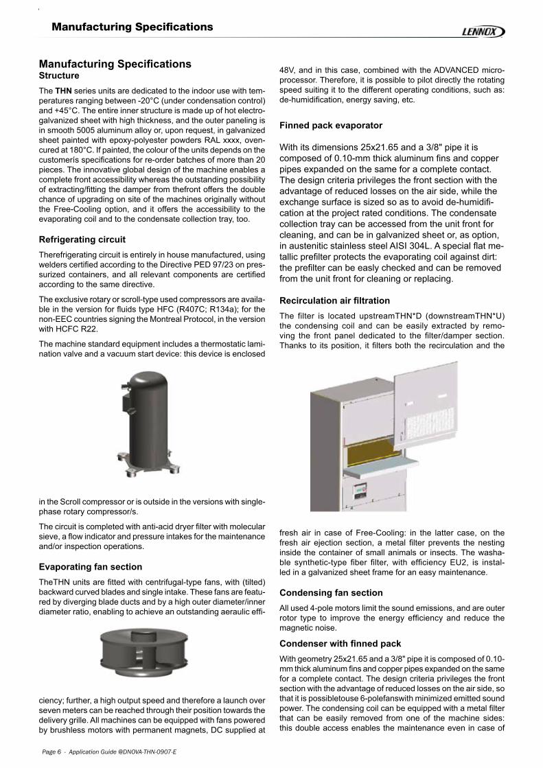
Evaporating fan sectionTheTHN units are fitted with centrifugal-type fans, with (tilted) backward curved blades and single intake. These fans are featu-red by diverging blade ducts and by a high outer diameter/inner diameter ratio, enabling to achieve an outstanding aeraulic effi-
ciency; further, a high output speed and therefore a launch over seven meters can be reached through their position towards the delivery grille. All machines can be equipped with fans powered by brushless motors with permanent magnets, DC supplied at
48V, and in this case, combined with the ADVANCED micro-processor. Therefore, it is possible to pilot directly the rotating speed suiting it to the different operating conditions, such as: de-humidification, energy saving, etc.
Finned pack evaporator
With its dimensions 25x21.65 and a 3/8" pipe it is composed of 0.10-mm thick aluminum fins and copper pipes expanded on the same for a complete contact. The design criteria privileges the front section with the advantage of reduced losses on the air side, while the exchange surface is sized so as to avoid de-humidifi-cation at the project rated conditions. The condensate collection tray can be accessed from the unit front for cleaning, and can be in galvanized sheet or, as option, in austenitic stainless steel AISI 304L. A special flat me-tallic prefilter protects the evaporating coil against dirt: the prefilter can be easly checked and can be removed from the unit front for cleaning or replacing.
Recirculation air filtrationThe filter is located upstreamTHN*D (downstreamTHN*U) the condensing coil and can be easily extracted by remo-ving the front panel dedicated to the filter/damper section. Thanks to its position, it filters both the recirculation and the
fresh air in case of Free-Cooling: in the latter case, on the fresh air ejection section, a metal filter prevents the nesting inside the container of small animals or insects. The washa-ble synthetic-type fiber filter, with efficiency EU2, is instal-led in a galvanized sheet frame for an easy maintenance.
Condensing fan sectionAll used 4-pole motors limit the sound emissions, and are outer rotor type to improve the energy efficiency and reduce the magnetic noise.
Condenser with finned packWith geometry 25x21.65 and a 3/8" pipe it is composed of 0.10-mm thick aluminum fins and copper pipes expanded on the same for a complete contact. The design criteria privileges the front section with the advantage of reduced losses on the air side, so that it is possibletouse 6-polefanswith minimized emitted sound power. The condensing coil can be equipped with a metal filter that can be easily removed from one of the machine sides: this double access enables the maintenance even in case of

Application Guide @DNOVA-THN-0907-E - Page 7
Manufacturing Specifications
double installation on the container wall. A special flat metallic prefilter protects the condensing coil against dirt: the prefilter can be easly checked and can be removed from the unit front for cleaning or replacing.
Electric boardIt is located in a separate cabinet hidden on the front side by the recirculation air before it is cooled by the evaporating coil: this aspect is extremely important for both the component cooling and, at the same time, for preventing the condensation on the
bottom side of the board. All on-board systems comply with the EEC Directive ìLow tension 73/23î and with the related norms. Theaccess to the electric board is possible with operating unit
as it is completely separated from the air flow; the protection degree with open panel is IP20.
PackingThe THN units are packed on wooden pallet with anti-shock cardboard angles and upper protection in card-board/polystyrene. In the end, the whole packing is wrap-ped with protection transparent polythenel film.
Application fieldTHN units are to be used within the operating limits stated in this manual; failure to comply with said limits will invalidate the warranties provided in the contract of sale (Tab.2).
Tab.2 - Field of ApplicationsMODEL: THN 045 056 073 090 105 120 150 170
Power supply V/Ph/F 230VAC +/-10% / 1Ph / 50Hz 400VAC +/-10% / 3Ph+N / 50Hz 24VDC +/-16% - 48VDC +/-16% 24 VDC +/- 16% - 48 VDC +/- 16%
Minimum outdoor temperature ºC -20
Maximum outdoor temperature ºC 45 46 45 46 46 45
Min. indoor temperature / humidity C/R.H. 19 / 30%
Max. indoor temperature / humidity C/R.H. 35 / 50%
Storage conditions C/R.H. -10 / 90%
+55 / 90%

Page � - Application Guide @DNOVA-THN-0907-E
Manufacturing Specifications
InterconnectivityAll units can be connected with remote supervision systems by the use of "Gateway". When using the "mP" control of the "ADVANCED" type, there is the possibility of piloting directly a GSM modem able to send and receive SMS messages.
Up to max. 6 units can be connected for the stand-by – rotation
control, with mP BASIC, in LAN (Local Area Networking), while up to max. 15 units can be connected with ADVANCED type mP, sharing the operating parameters and enabling the stand-by rotation and re-start of the installed machines.
The interconnection possibilities, according to control type, are summarized in the two tables below (Tab.3 and Tab.4).
Tab.3 - mP ADVANCED
PROTOCOL SERIAL CARD GATEWAY NOTES Not necessary RS485 network connection Proprietary Carel RS485 RS485 / RS232 converter (PC485KIT) Connection with the supervision PC Modbus® RS485 Not necessary RS485 network connection BACnett™ RS485 Gateway BACnett™ RS485 network connection LonWorks® LON RS485 Not necessary For the dedicated programming, LON RS485 contact LENNOX S.p.A. Trend Trend serial Not necessary For the dedicated programming, contact LENNOX S.p.A. Tcp / Ip RS485 Gateway TCP / IP Ethernet network connection GSM RS232 GSM modem For the dedicated programming, contact LENNOX S.p.A. RS485 control local network PlantWatch + GSM modem PlantWatch operates as concentrator
Tab.4 - mP BASIC
PROTOCOL SERIAL CARD GATEWAY NOTES Not necessary RS485 network connection Proprietary Carel RS485 RS485 / RS232 converter (PC485KIT) Connection with the supervision PC Modbus® RS485 Gateway Modbus® RS485 network connection BACnett™ RS485 Gateway BACnett RS485 network connection LonWorks® - - - Trend - - - Tcp / Ip RS485 Gateway TCP / IP Ethernet network connection GSM RS485 control local network PlantWatch + GSM modem PlantWatch operates as concentrator

Application Guide @DNOVA-THN-0907-E - Page 9
Manufacturing Specifications
Fig. 2 -THN*D - Machine main components 3
Tab.5 -THN*D - Machine Main Components
REF. DESCRIPTION
1 Compressor 2 Evaporator 3 Evaporator fan 4 Evaporator air filter 5 Condenser 6 Condenser fans 7 Condenser air filter 8 Electrical heaters 9 Free-Cooling damper 10 Motor (Free-Cooling damper) 11 Electric board
Page �0 - Application Guide @DNOVA-THN-0907-E
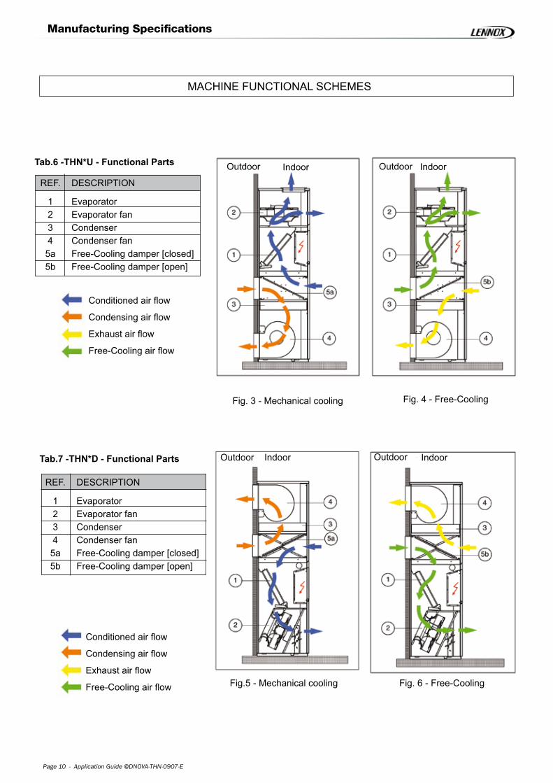
Tab.7 -THN*D - Functional Parts
Manufacturing Specifications
MACHINE FUNCTIONAL SCHEMES
Tab.6 -THN*U - Functional Parts
REF. DESCRIPTION
1 Evaporator 2 Evaporator fan 3 Condenser 4 Condenser fan 5a Free-Cooling damper [closed] 5b Free-Cooling damper [open]
Indoor Outdoor Indoor Outdoor
Fig. 3 - Mechanical cooling Fig. 4 - Free-Cooling
Fig.5 - Mechanical cooling Fig. 6 - Free-Cooling
REF. DESCRIPTION
1 Evaporator 2 Evaporator fan 3 Condenser 4 Condenser fan 5a Free-Cooling damper [closed] 5b Free-Cooling damper [open]
Conditioned air flow
Condensing air flow
Exhaust air flow
Free-Cooling air flow
Outdoor Indoor
Conditioned air flow
Condensing air flow
Exhaust air flow
Free-Cooling air flow
Outdoor Indoor

Application Guide @DNOVA-THN-0907-E - Page ��
Control Software and Hardware
Control Software and Hardware
BASIC [Carel ÏAC] + ADVANCED [Carel pCO2]
The THN units can be supplied with two microprocessor control levels:
• BASIC with user interface 4x20 LCD• ADVANCED
Optional configuration:
- with user interface 4x20 LCD
- with built-in display 4x20 LCD
For the ADVANCED controls, a remote display is available too, and can be positioned up to 200 m far with a simple plug-in connection with phone-type cable.
All microprocessors, BASIC, ADVANCED and ADVANCED with built-in display 4x20 LCD, enable to control completely the units, such as:
mP ADVANCED [Carel pCO2] technical data
• Flash memory: ..........1 MByte expandable to 16 MByte • RAM memory: ...........256 kByte expandable to 1 MByte • Parameter memory: ..2 kByte• Analog inputs: ...........B4 - B5 = two inputs for NTC probes (-50 # 100°C), PT1000 (-100 # 200°C) / clean inputs
B1 - B2 - B3 = three inputs for NTC probes (-50°C # 100°C); voltage 0 # 1Vdc/0 # 10 V dc, current 0 # 20 mA / 4 # 20 mA
• Analog outputs: .........Y1 - Y4 = four opto-insulated outputs 0 # 10 V dc, max. load 10 mA (1 kΩ) • Digital inputs: ............ ID1 - ID8 = eight opto-insulated inputs 24 V ac 50/60 Hz / 24 V dc• Digital outputs: ..........No.1 # No. 8 = electro-mechanical relays
• Sensors:
- room temperature to keep the inner set-point- outer temperature to pilot the Free-Cooling damper - delivery temperature to prevent the risks of thermal
shocks of the room electronic equipment- condensing pressure (optional)- evaporating pressure (optional)
• Functions:- room temperature management - reading of the relative humidity (optional) - control of the air outlet min. temperature in the environ-
ment- control of the air de-humidification by reducing the fan
speed (with optional sensor and with optional dc fans)- heating (optional)- alarm control equipped with clean contacts for the re-
mote connections of visual and sound systems- stand-by management of two units.
The LAN connection by the ADVANCED microproces-sor, ensures other functions such as SMART, Free-Coo-ling, modem sharing, etc.
- clean contacts for every other type of alarm (optional)- from the microprocessor it is possible to select the auto-
matic restart after a voltage lack- min. time between two compressor start-ups- remote interface, up to 200 m, directly connected using
a LAN connection (for mP ADVANCED)- possibility of connecting the unit with a supervision sys-
tem (optional)- 2 password levels to access the unit configuration- clock card for recording the even date and time- hour-counter to enable a scheduled maintenance of the
fans, compressors and filters- automatic switching between two compressors for each
unit with double refrigerating circuit. The algorithm can be selected to achieve the "one in operation – one in stand by strategy or to achieve a balanced operating time between two circuits. The second circuit, too, is started when exceeding the preset set-point tempera-ture, independently from the selected control strategy.
Note: the ADVANCED control is available for all units with double circuit, only.
Control Software and Hardware
Fig. 6 - Free-Cooling

Page �� - Application Guide @DNOVA-THN-0907-E
mP BASIC [Carel ÏAC] technical data
• Analog inputs: ............B1 - B2 - B4 = three inputs for NTC temperature probes (10 kΩ a25°C) B3 = one input for humidity/pressure probe (0 # 1Vdc/4 # 20 mA) + V = probe supply output (14 V dc, 30 mAmax.)
• Analog outputs: .........Y1 = output 0 # 10 V dc, not opto-insulated, referred to the supply potential G0, max. load 10 mA (1 k$ ) Y2 = phase disconnection output
• Digital inputs: ............ ID1 - ID10 = ten non-optoinsulated inputs referred to the supply potential G0, supplied with 24 V ac, current absorbed by each input 6.5 mAat24Vac
• Digital outputs: ......... OUT1 - 5 = 5 SSR, 24 V ac, 1 A, with min. current 20 mA OUT6 - C6 = 1 relay, 220 V ac OUT7 - C7 = 1 relay, 220 V ac
Control Software and Hardware

Application Guide @DNOVA-THN-0907-E - Page ��
Fig. 7 - Operating diagram
List of the Main Options
List of the Main Options
1 ADVANCED microprocessorP r o g r a m m a b l e m i c r o p r o c e s -sor with 16 bit and high performances.
2 Air differential pressure switch
3 Double supply• AC main supply from the mains:
- Compressor/s - Fan/s of the condensing section- Heating
• Auxiliary supply 48 VDC(24 V DC, upon request): - Microprocessor- Evaporating section fan
Note: it is possible to activate the fan speed control to ena-ble the coil energy saving during its operation.
- Damper servomotor
4 Refrigerant R134aFor extreme outdoor conditions up to +45°C.
5 Free-Cooling with damperThanks to the unit designing principle, it is possible to carry out the "upgrading on site" on the units not equipped with the Free-Cooling
6 ETV-T "E lec t ron ic Thermosta t ic Va lve Technology"
For applications where the direct Free-Cooling is not possi-ble.This solution enables to reduce the energy consumption up to 50% compared to the standard units when the outdoor tempe-rature is below 20°C.
7 Humidity sensorFor the enthalpic control in the Free-Cooling situa-tions (combined with the mP ADVANCED control).
8 Condensation control
9 Interconnectivity
• Serial port:-RS232 -RS485
• Communication protocol:-Carel -Modbus®-LonWorks®
-BACnett-TCP-IP-GSM modem (complete management through SMS Ser-
vices).
Free-Cooling TechnologyThe innovative Free-Cooling system enables to reach outstan-ding efficiency levels, above all when operating simultaneously with the mechanical cooling: this situation, in many central European climate areas, represents over 50% of the yearly total hours.
The damper is further designed to be integrally extracted, thus enabling a complete maintenance possibility as well as the access to the condensate collection tray.
TheTHN designing concep t enables the upgrading on site of units not equipped with the Free-Cooling option; this is impor-tant in such cases where it is necessary to have a unit stock at disposal.
The temperature sensors installed at delivery, intake and fresh air control completely the damper, improving its energy efficiency and avoiding the risk of inlet air at temperatures lower than the limit allowed by the electronic equipment.
In case of combination with DUAL supply, mains + DC UPS, the Free-Cooling can enable to control the climate even in emer-gency situations and, if the two units are reciprocally connected , it can implement all strategies for avoiding to lose the control of the inner set point of the container (see Fig. 7).
Cooling capacity
True container thermal requirement
Free-Cooling: capacity of two units Room Set Point
FFT1 FFT2
Free-Cooling: capacity of one unit Room Set Point
Room air temperatureRooom set point

Page �� - Application Guide @DNOVA-THN-0907-E
List of the Main Options
Damper servomotor with spring return
It positions the dampers completely open or completely closed at the customerís choice in case of power lack: with an opera-
tion signal connected with a fire alarm, the damper is usually positioned closed, to enable the operation of the automatic switching -off systems.This option must be defined at the order.
Clogged filter sensorThis differential pressure sensor detects the filter clogging and generates an alarm displayed by the microprocessor control.
HeatingIt is performed by using heaters in extruded aluminum, with high thermal exchange surface: this aspect enables to match reduced thermal inertias with reduced surface temperatures,
to the advantage of a full use safety. Each heating element is protected by a safety thermostat directly acting on the supply.
Outer panelingThe standard supply includes panels in painted galvanized sheet metal RAL7035.
Surface treatments on finned coils
An efficient protection against corrosive agents is guaranteed by the copper-copper version, the cataphoresis protection and the use of hydrophile pre-treated aluminum: the protection grade is reported in the mentioned order.
RefrigerantsAccording to the norm EEC 2037/00, the THN units can operate with:
• HFC R407C as standard
• HFC R134a (optional)
• HCFC R22 Export non-EEC in the countries signing the Montreal protocol
The unit is supplied: tested and ready to be started up on the site.
AlarmsIt reports high and low priority alarms on clean contacts. In case of ADVANCED microprocessor, it is possible to have a subdivi-sion of the alarm type in the terminal board of the electric panel and, generally, it is possible to arrange Custom solutions accor-ding to the different supply standards of the phone companies.
Air distribution grillesThe wall-mounted air distributions grilles are made of extru-ded aluminum, with single row of adjustable fins and accid ent-prevention protection net on the delivery. In case of Free-Cooling unit, a further net is arranged on the air outlet to pre-vent the unwished entry of small animals and/or insects.

Application Guide @DNOVA-THN-0907-E - Page ��
Tests and Reference Standards
Tests and Reference Standards
SafetyThe THN units have been designed, manufactured and tested according to the directives of the European Union:
• 98/37/EC (former 89/392/EEC, 91/368/EEC, 93/68/EEC)
• 89/336/EEC
• 73/23/EEC
Electric boardsThe electric boards comply with EN 60204-1.
Electro-magnetic compatibilityThe THN units complies with the following EMC standards:
S EN 50081-1, Emissions
(îGeneric emission standard, Part 1: residential, commercial and light industrialî, January 1992)
S E N 5 0 0 8 2 - 2 , E l e c t r o - m a g n e t i c c o m p a t i b i l i t y ("Generic emission standard, Part 2: industrial environment", March 1995)
ConformityEach THN unit is supplied complete with test certificate and conformity certificate according to the Directives of the European Union.The units are "CE" marked.

Page �� - Application Guide @DNOVA-THN-0907-E
Technical Data
Technical Data
Tab.8 - Performance table
MODEL: THN 045 056 073 090 105 120 150 170
Refrigerant [Ashrae] R407C
Total cooling capacity
[I.T. 27ºC; R.H. 40% / O.T. 35ºC] kW 4.50 5.60 7.10 8.97 1 0.85 11.85 14.98 17.20
Power supply [standard] V/Ph/F 230/1/50 400/3+N/50
Power supply [option 1] V/Ph/F - 400/3+N/50 230/1/50
Power supply [option 2] V/Ph/F 230/1/50+
230/1/50 400/3+N/50+230/1/50
Power supply [option 3] V/Ph/F 230 / 1 / 50 + 48 VDC 400 / 3+N / 50 + 48 VDC
Power supply [option 4] V/Ph/F - 400/3+N/50 + 48VDC 230 / 1 / 50 + 48 VDC
Total absorbed power W 1 810 2330 2990 3950 4400 5000 6040 7030
Total absorbed current A 8.3 14.3 13.6 11.8 12.5 13.6 17.8 18.6
FLA A 15.1 16.0 19.6 17.5 17.5 19.5 21.7 25.7
LRA A 30 47 61 40 46 50 65 74
Indoor fan/s absorbed power
- 230V / 1Ph / 50Hz W 108 310 470 520
Indoor fan/s absorbed power
- 48VDC [option W 100 260 350 450
Indoor air flow m3/h 1450 2100 3020 3800
Indoor air flow
- Free Cooling [40 Pa] m3/h 1320 1320 1980 2850 2810 2810 3550 3550
Free Cooling temperature ºC 17.8 15.5 17.0 18.2 16.3 15.4 15.3 13.6
Air filter efficiency - G3
Sound power level dB(A) 69 72
Sound pressure level
[10m in free field] dB(A) 58 61
Compressor Type Rotary Scroll
No. 1
Refrigerating circuit No. 1
Oil charge [each compressor] dm3 0.44 1.00 1.00 1.10 1.10 1.10 1.36 1.65
Indoor coil front surface m2 0.30 0.38 0.42
Outdoor coil front surface m2 0.33 0.45 0.52
Condenser air flow m3/h 2250 3750 4700
Condenser fan -THN*U 1 1 2
-THN*D No. 1 2 2
Width x Height x Depth mm 800 x 1850 x 550 1000 x 1850 x 550 1160 x 1850 x 550
Weight kg 120 128 135 195 200 210 245 250
FLA = Max. operating current. LRA = Pickup current
Application Guide @DNOVA-THN-0907-E - Page �7
Dimensional Drawings
Dimensional Drawings
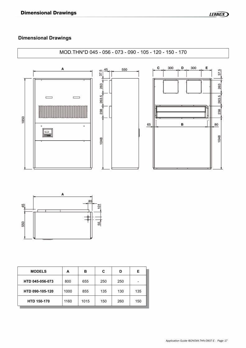
MOD.THN*D 045 - 056 - 073 - 090 - 105 - 120 - 150 - 170
FRONT VIEW SIDE VIEW
TOP VIEW
REAR VIEW
MODELS A B C D E
HTD 045-056-073 800 655 250 250 -
HTD 090-105-120 1000 855 135 130 135
HTD 150-170 1160 1015 150 260 150

Page �� - Application Guide @DNOVA-THN-0907-E
Dimensional Drawings
MOD.THN*U 045 - 056 - 073 - 090 - 105 - 120 - 150 - 170
THN*U 045-056-073-150-170
REAR VIEW
REAR VIEW
FRONT VIEW SIDE VIEW
TOP VIEW
THN*U 090-105-120
MODELS A B C D E F
THN*D 045-056-073 800 655 150 350 - 600
THN*D 090-105-120 1000 - - - - 800
THN*D 150-170 1160 1015 150 260 150 1000
MODELLEN A B C D E F

Application Guide @DNOVA-THN-0907-E - Page �9
Refrigerant Circuit
Refrigerant Circuit
MOD.THN 045 - 056 - 073 - 090 - 105 - 120 - 150 - 170
Tab.9 - Refrigerant Circuit
REF. DESCRIPTION REF. DESCRIPTION
1 Compressor 6 Sight glass
2 Condenser 7 Low pressure switch (LP)
3 Thermostatic valve 8 High pressure switch (HP)
4 Evaporator 9 Condensing pressure probe
5 Filter dryer
REAR VIEW
REAR VIEW


www.lennoxeurope.com
www.lennoxbelgium.com
www.lennoxczech.com
www.lennoxfrance.com
www.lennoxdeutschland.com
www.lennoxnederland.com
www.lennoxpolska.com
www.lennoxportugal.com
www.lennoxrussia.com
www.lennoxdistribution.com
www.lennoxspain.com
www.lennoxukraine.com
www.lennoxuk.com
www.lennoxdistribution.com
@DNOVA-THN-AGU-0907-E
BELGIUM, LUXEMBOURG
CZECH REPUBLIC
FRANCE
GERMANY
NETHERLANDS
POLAND
PORTUGAL
RUSSIA
SLOVAKIA
SPAIN
UKRAINE
UNITED KINGDOM AND IRELAND
OTHER COUNTRIES
Due to Lennox’s ongoing commitment to quality,
the Specifications, Ratings and Dimensions are
subject to change without notice and without
incurring liability.
Improper installation, adjustment, alteration,
service or maintenance can cause property
damage or personal injury.
Installation and service must be performed by a
qualified installer and servicing agency.