
DN 32 50 Hz - Penelly · ... Clamped connection for standard pipes to for standard pipes to DIN...
20
Amarex N S 32-160 / 0 2 YL G-160 Type series Impeller type (S) Hydraulics size Motor designation Impeller diameter Number of poles Motor version (YLG only) Material variant G only Type series booklet 2563.51/3-10 Amarex ® N S 32 Submersible motor pumps DN 32 50 Hz Applications Amarex N S 32-160 submersible motor pumps are used for pumping waste water in intermittent operation, e.g. F Domestic waste water F Raw water F Waste water containing faeces Operating data Capacity Q up to 16 m 3 /h, 4.4 l/s Head H up to 29 m Motor rating P 2 1.5 kW Fluid temperature t up to 40 ¥ C Enclosure IP 68 to EN 60 529 / IEC 529 Design Wet-installed in stationary and transportable design. Submersible, single-stage, single-entry, non-self-priming close-coupled unit. Hydraulic system: with cutter (S). Designation Drive Asynchronous motor, 400 V, 50 Hz, direct starting, Max. switching frequency: 30 starts per hour YLG version in accordance with ATEX 100a, motor Ex d IIB T4, LCIE 07 ATEX 6016 X. Shaft seal -- motor end: 1 shaft seal ring -- pump end: 1 bi-rotational mechanical seal with oil reservoir filled with environmentally-friendly oil Bearings Grease-packed rolling element bearings sealed for life. Motor variants No variants available Please note: Variable-speed operation of this pump is not allowed. YL ⇒ motor only with explosion protection T4 (40 ¥ C) Operating mode S1 -- submerged (max. 25 m) Operating mode S3 – not submerged (see dimension table) -- EN 12 050 LGA approval No.: 7381257--01z
Transcript of DN 32 50 Hz - Penelly · ... Clamped connection for standard pipes to for standard pipes to DIN...

Amarex N S 32-160 / 0 2 YL G-160Type seriesImpeller type (S)
Hydraulics size
Motor designation
Impeller diameter
Number of polesMotor version (YLG only)
Material variantG only
Type series booklet2563.51/3-10 Amarex® N S 32
Submersible motor pumpsDN 3250 Hz
ApplicationsAmarex N S 32-160 submersible motor pumps are used forpumping waste water in intermittent operation, e.g.F Domestic waste waterF Raw waterF Waste water containing faeces
Operating dataCapacity Q up to 16 m3/h, 4.4 l/sHead H up to 29 mMotor rating P2 1.5 kWFluid temperature t up to 40 ¥CEnclosure IP 68 to EN 60 529 / IEC 529
DesignWet-installed in stationary and transportable design.Submersible, single-stage, single-entry, non-self-primingclose-coupled unit.Hydraulic system: with cutter (S).
Designation
DriveAsynchronous motor, 400 V, 50 Hz, direct starting,Max. switching frequency: 30 starts per hourYLG version in accordance with ATEX 100a,motor Ex d IIB T4, LCIE 07 ATEX 6016 X.
Shaft seal-- motor end: 1 shaft seal ring-- pump end: 1 bi-rotational mechanical seal with oil
reservoir filled with environmentally-friendlyoil
BearingsGrease-packed rolling element bearings sealed for life.
Motor variantsNo variants availablePlease note: Variable-speed operation of this pump is notallowed.YL ⇒ motor only with explosion protection T4 (40 ¥C)Operating mode S1 -- submerged (max. 25 m)Operating mode S3 – not submerged (see dimension table)
-- EN 12 050LGA approval No.: 7381257--01z

Double winding temperaturemonitoring enables automa-tic operation, even whereexplosion protection require-ments have to be met.
Product Advantages at the Example of
Amarex N S 32-160 YLGto Our Customers’ Benefit
Absolutely watertight cable entry.Multiple safety due to:
Individual conductors stripped, tinnedand sealed in resin.
New kind of cable entry
Your benefit:Easy-to-connect polarisedcable entry enables fastcable installation / removal
Shaft made ofcorrosion-resistantstainless steel
Your benefit:No corrosion pro-blems, thereforelong service lives.
Oil reservoir filled withenvironmentally-friendly,non-toxic oil;food-approved
Your benefit:Our contribution toenvironmentalprotection
Bearings sealed on both sidesand lubricated for life to givelong service life
Your benefit:Maintenance-free, ideal forcontinuous-duty pumps
Motor for operating mode S1,thermal class F,explosion-proof in T4.
Your benefit:Maximum operating reliabilitythanks to optimum motorselection
Your benefit:Motor protected fromoverheating
Your benefit:A solution ensuring longservice life. Perfect motorprotection.
Shaft sealed by 1 shaftseal ring (motor-end) and1 bi-rotational mechanicalseal with SiC/SiC contactfaces (pump-end).
Your benefits:A single tool will dismantle the entirepump, which makes servicing somuch easier. Easy to dismantle evenafter years of operation.
All screwed connections made ofstainless steel, M6 hex. socket headcap screwsYour benefit:
Optimal hydraulicperformance andefficiency withcontaminated fluids
Optimum hydraulicdesign
Automatic, bolt-freeconnection for stationaryinstallation; leakageprevented by elastic sealing.
Your benefit:The most simple and at thesame time mostoperator-friendly solution:Easy installation andremoval of the pump.
Your benefit:The pump can be operated safelyeven in the event of damage to thecable sheath and core insulation.
Amarex N S 32
2

Amarex N S 32
3
Materials
Variant G
Pump casing JL 1040
Intermediate casing JL 1040
Impeller JL 1040
Cutter 1.2842 (90Mn V8G)
Shaft 1.4021
Shaft seal ring(motor-end) NBR
Mechanical seal(pump-end) SiC / SiC
Screws/bolts A2
Sealing elements NBR
Scope of supplyPump (Ident. No. 39 ... ...) and accessories in separatepackages, available ex stock.
D Pump unit (P1):-- Material variant: Grey cast iron-- Motor design: Explosion-proof (YL)-- Cable gland: Totally watertight, resin-mounted-- Complete pump, ready for installation, with 10m power sup-
ply cable 7 x 1.5 mm2
-- Standard finish: Surface treatmentSA2 1/2 SIS 055900
Primer: Iron oxide (dipped), 35 -- 40 µmTop coat: Environmentally-friendly KSB
standard coating, approx.40 µm,RAL 5002 (ultramarine blue)
D Installation parts for stationary installationP2 Guide hoop installation parts for
ET = 1.5 m / 1.8 m / 2.1 m only+ P5 (Claw)
P7 (Chain and shackle) ET = 2 mor P4 (guide wire arrangement) ET = 4.5 m
+ P5 (Claw)P7 (Chain and shackle) ET = 4.5 m
(see chapter on suggested installation layouts)ET = Installation depth from the lower edge of the access ope-ning to the bottom of the pump sump.
D Installation parts, transportable designP6 (Foot)
D Installation parts, single guide rail arrangementP4 + P5 (Guide rail arrangement)P5 ClawP7 Chain and shackle, ET = 4.5 m
D Installation parts, twin guide rail arrangementP4 + P5 (Twin guide rail arrangement)P5 (Claw + adapter)
Guide hoop Guide wire Single guide rail Twin guide rail
P1
P7
P5P2
P1
P7
P5P4
P1P7
P5
P4
P1
P7
P5P4

Amarex N S 32
4
Thermal motor monitoringExplosion-proof design The motor is protected by two independent monitoring circuits to prevent overheating.
Pump size Temperature monitoring circuit(with automatic reset and start-up)
Limiting circuit(cuts out the pump when the temperature limit isreached; automatic reset and re-start is notpermitted)
Amarex N S 32 Bimetal switch to be connected directly with thecontrol circuit of the motor contactor
Bimetal switch to be connected via a tripping unitwith manual reset
VariantsNo design variants available(pump BT1)
Impeller type
Impeller with cutter
Impeller with cutting device for handlingdomestic waste water containing fibres
F Domestic waste waterF Raw waterF Faeces
S

K2563--52--32S Rev.0
0 2 4 6 8 10 12 14 16 18m#/h
0 20 40 60US.gpm
0 20 40 60IM.gpm
0
5
10
15
20
25
30
32
m
0
20
40
60
80
100
ft
0 1 2 3 4 5l/s
0.5
1.0
1.5
2.0
kW 1
2
hp
0 2 4 6 8 10 12 14 16 18m#/h
Ø160
Ø160
Characteristic curves to ISO 9906-2A. They correspond to the effective motor speed.
FörderhöheHeadHauteurPrevalenzaAltura manométríca
LeistungsbedarfPower inputPuiss. hyd. abs.Potenza ass.Potenciarequerida
Fördermenge/Flow/Débit/Portata/Capaciteit/Caudal
Kugeldurchgang/Free passage/Passage intégral 6 mmPassaggio libero/Kogeldoorgang/Paso libre
Amarex N S 32
5
Amarex N S 32-160 2900 1/min
LaufradformImpeller type
Forme de roueTipo girante
Tipo de rodete
freier Durchgangfree passage
section de passagepassaggio libero
paso libre
6 mm
Amarex N S 32-160/ ... 50 Hz -- 3~ 400 V 2900 1/min
ImpellerNo.
Amarex NS 32-160/...
Power inputP1 [kW]
RatedpowerP2 [kW]
RatedcurrentIN [A]
StartingcurrentID [A]
Fluidtemperature
t [oC]
Weight
[kg]
Ident. No.
160 ... / 02 YLG 2,05 1,5 3,4 18,2 40 29 39 100 380

Amarex N S 32
6
Outline drawing – stationary and transportable model
StationaryinstallationAmarex
NS32-160
withguidewire
StationaryinstallationAmarex
NS32-160
withsingleguiderail
StationaryinstallationAmarex
NS32-160
withtwinguiderails
with
guidehoop
notinKSB’sscope
ofsupply
1 )Lowestswitch-offpointfor
automaticoperation
2 )Minimum
subm
ergencefor
continuous
operation
RS=lowestswitch-offpointinslurp
mode
Clampedconnection
Transportableversion
Pum
pflangeDN2
notinKSB’sscope
ofsupply
Flangeofduckfoot
bend
DN3
ISO7005
PN10--PN16
DIN
2501
PN10--PN16

Stationary installation Amarex N S 32-160 with guide wire
1) Lowest switch-off point for automatic operation
2) Minimum submergence for continuous operation
RS = lowest switch-off point in slurp modeGuide wire arrangement with inclined claw
Amarex N S 32
7
Outline drawing – Stationary installation with guide wire

Stationary installation Amarex N S 32-160 with single guide rail
1) Lowest switch-off point for automatic operation
2) Minimum submergence for continuous operation
RS = lowest switch-off point in slurp mode Single guide rail arrangement with inclined claw
not included in KSB scope of supply
Amarex N S 32
8
Outline drawing – Stationary installation with single guide rail

Stationary installation Amarex N S 32-160 with guide hoop
1) Lowest switch-off point for automatic operation
2) Minimum submergence for continuous operation
RS = lowest switch-off point in slurp mode
Guide hoop arrangement with inclined claw
Amarex N S 32
9
Outline drawing – Stationary installation with guide hoop

Amarex N S 32
10
Transportable version
Suggested installation layout No. 1Vertical hose connection
Suggested installation layout No. 2Vertical hose connection
Suggested installation layout No. 3Horizontal hose connection
Suggested installation layout No. 4Vertical hose connection
Suggested installation layout No. 5Horizontal hose connection
P1 to P27 see accessories

Amarex N S 32
11
Suggested layouts for stationary installation
Layout No. 1 Layout No. 2Guide hoop arrangement Direct connection to discharge pipeSingle-pump station for 1.5 -- 1.8 m installation depth Single-pump stationDuckfoot bend Suspended installation
Layout No. 3 Layout No. 4Single-pump station for 4.5 m installation depth Duplex-pump station for 4.5 m installation depthOptionally with guide wire Optionally with guide wire
single guide rail single guide railor twin guide rails or twin guide rails
Duckfoot bend Duckfoot bend

Amarex N S 32
12
Suggested installation layouts Amarex N in stationary installation
Amarex N S 32 ø A B ø D E G K L M N O DN1
1 pump2 pumps
430--
165165
800800
--300
7575
150150
5757
--400
--600
--151
3232
The dimensions given are minimum dimensions in mm.Pump dimensions see dimensions table

Amarex N S 32
P2
or
P4
P8
P27 P2
or
P4
P2
or
P4
13
Dischargeconnectionoptionsonsameduckfootbendas
Amarex
NDN50
Flanged
connection
2-inch
threaded
connectionintheflange(DN50)
Clamped
connection
forstandardpipesto
forstandardpipesto
DIN
2440
/DIN
2441
DIN
2440
/DIN
2441
/DIN
2448
with
pipe
OD60.3mmforD
N50
with
pipe
OD60.3mm–steelforDN50
Dia.63mm–PVC(IS
O3606)forDN50
Dia.63mm–PVC(IS
O3606)forDN50

Accessories Amarex N S 32
14
Installation parts for stationary installation
Item Illustration Description Connection Ident. No. Netweightapprox.kg/unit
P2+P5+P7 (guide hooparrangement)
Installation parts for stationarywet-well installation, consisting of:duckfoot bend DN 50,guide hoop, bolts, anchor bolts,claw with stainless steel bolts,2 m chain (galvanised steel) andshackle 1.4401
DN 50 -- DN 3: DIN ISO ASME-- straight claw
Installation depth 1.5 m1.8 m2.1 m
-- inclined clawInstallation depth 1.5 m
1.8 m2.1 m
39 022 21039 022 21139 022 212
39 023 10239 023 10339 023 104
11.012.013.0
16.017.018.0
P4 + P5 + P7 (guide wirearrangement)
Installation parts for stationarywet-well installation, installationdepth 4.5 mconsisting of:duckfoot bend,suspension bracket, mountingbracket,10 m guide wire,bolts, anchor bolts,claw with stainless steel bolts,5 m chain (galvanised steel) andshackle 1.4401
DN 50 -- DN 3 : DIN ISO ASME-- straight claw
-- inclined claw
39 022 196
39 023 105
14.5
19.5
P4 + P5 + P7 (single guide railarrangement)
Installation parts for stationarywet-well installationconsisting of:duckfoot bend, mounting bracket,bolts, anchor bolts,claw with stainless steel bolts,5 m chain (galvanised steel) andshackle 1.4401
DN 50 -- DN 3 : DIN ISO ASME-- straight claw
-- inclined claw
39 022 204
39 023 107
14.0
19.0
P4 + P5 + P7 (double guide railarrangement) DN 50
Installation parts for stationarywet-well installation, consisting of:duckfoot bend, mounting bracket,stainless steel bolts, adapter, anchorbolts,5 m chain (galvanised steel) andshackle 1.4401
DN 50 -- DN 3 : DIN ISO ASME-- inclined claw 39 023 002 14.0
P5 Claw for Amarex N S 32 claw JL 1040 with stainless steelbolts,-- for guide wire-- for guide hoop-- for single guide rail
DN 32/50 -- straight claw
-- inclined claw
39 022 248
39 023 108
1.0
5.0
P5 (twin guide railarrangement) Claw
Claw, JL 1040, with stainless steelbolts
DN 32/50 -- inclined claw 39 022 990 6.5
Conversion kit, consisting of:mounting bracket, stainless steelbolts, adapter, anchor bolts
Please note:required for converting a system withguide wire, single guide rail or guidehoop into a system with twin guiderailsCaution:Supply of an appropriate clawdesigned for twin guide rails ismandatory!
DN 50 39 022 984 1.6

50
Accessories Amarex N S 32
15
Installation parts for transportable model
Item Illustration Description Connection Ident. No. Net weightapprox. kg/unit
P6 Feet (3) Amarex N DN 32 39 023 085 0.25
(for uneven mounting surfaces only)Pump foot padincluding screws(can be used in combination with feet only!)
Amarex N DN 32 to 100 39 022 262 0.6
Chain for stationary and transportable models
Item Illustration Description Sizes Safe working loadkg
Ident. No. Net weightapprox. kg/unit
P7 Chain (galvanised steel),shackle 1.4401 andhook 1.45712 m B5 x 35 160 19 141 819 1.5
5 m B5 / 6 160 19 141 820 2.7
Chain, shackle 1.4401and hook 1.45712 m D5 160 19 143 335 1.7
5 m D5 160 19 143 336 2.7
Polypropylene liftingrope5 m, with shackle 1.4401and hook 1.4571
180 39 021 975 2.5
Shackle 1.4401, straighttype, with stainless steelscrew bolt
160 01 019 282 0.5
Accessories for stationary and transportable pump setsItem Illustration Description Connection for pump
sizeIdent. No. Net
weightapproxapprox.kg/unit
P8(Clamped connection)
P8P2orP4
Flange for pipe coupling PN 10at the flange of the duckfoot bendMating dimensions to PN 16
DN 50 / R 2 pipe X 19 551 111 1.0
P9 PVC adapter for hose connectionwith 1 hose clipPlastic hoseInside diameter 63, item P19
R 2 X 11 191 498 1.0

32 50
Accessories Amarex N S 32
16
Accessories for stationary and transportable pump setsPlease note:For Amarex N S 32--160 accessories please refer to the suggested installation layouts on page 10.
Item Illustration Description Connection Size Ident. No. Netweightweightapprox.kg/unit
P14 Elbow with male/female threadcast iron, galvanisedUse items P27 and P30 for assembly with pump
R 2 X 00 241 966 0.3
P17 Storz rigid coupling with male threadAluminium
C 52 / G 2 A X 00 524 370 0.2
P18 Plastic hoseDIN 14 811with integrated C couplings
C 52 5 mC 52 10 mC 52 20 m
XXX
00 522 26200 522 26300 522 264
1.83.46.6
P19 Plastic hosewithout coupling (max. 30 m)DIN 14 811
Ø 63 5 m10 m20 m30 m
XXXX
39 018 68839 018 68939 018 69039 019 073
1.73.46.810.2
P20 Hose clip DIN 3017Cr steel
*) For plastic hose Ø63 item 19
B 50 *) X 39 000 515 0.10.10.1
P21 RK swing check valvePlastic, ISO 7/Iwith full port and drain plug
Not suitable for pumped drainage
Rp 2 X 01 009 773 0.6
P22 Socket gate valvePN 10 -- 12 DIN 3352CuZn
Rp 2 X 00 411 503 0.8
P23 Ball check valve with flange PN 10Cast
Rp 2 39 000 510 3.6
P27 Screwed flange PN 16 for flanged elbow DN 50 / Rp 2C50 with bolts, gasket and nuts
X 19 551 353 2.0
Screwed flange PN 40 for pump DN 32 / Rp 1 1/4including bolts
X 39 023 087 1.8
P30 Adapter with reduced male thread M4 2 x 1 1/4EN 1042K
X 01 135 663 0.3
Hand pump,wall mounting, cast iron, suction-side connection Rp 1 1/2
X X 00 520 485 12.0
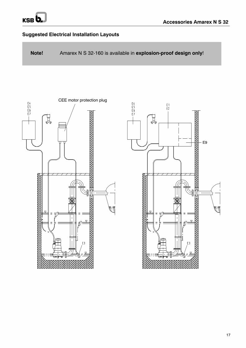
CEE motor protection plug
E9
Accessories Amarex N S 32
17
Suggested Electrical Installation Layouts
Note! Amarex N S 32-160 is available in explosion-proof design only!
Accessories Amarex N S 32
18
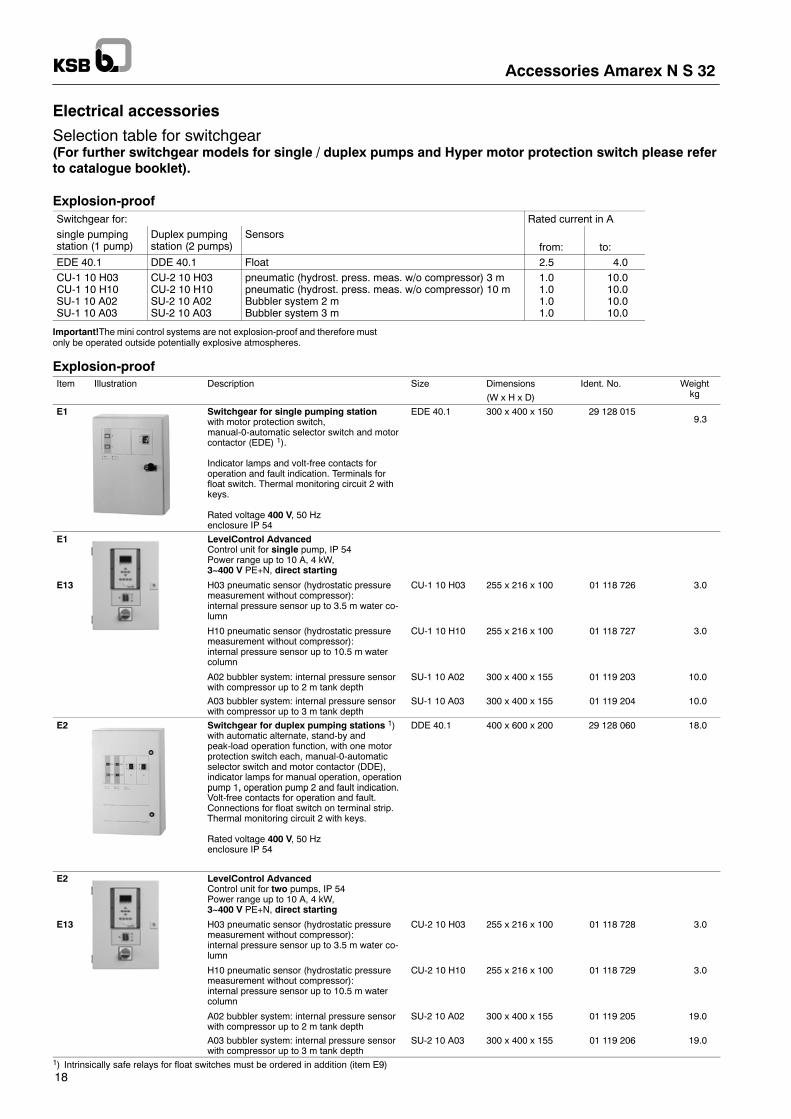
Electrical accessories
Selection table for switchgear(For further switchgear models for single / duplex pumps and Hyper motor protection switch please referto catalogue booklet).
Explosion-proofSwitchgear for: Rated current in Asingle pumpingstation (1 pump)
Duplex pumpingstation (2 pumps)
Sensorsfrom: to:
EDE 40.1 DDE 40.1 Float 2.5 4.0CU-1 10 H03CU-1 10 H10SU-1 10 A02SU-1 10 A03
CU-2 10 H03CU-2 10 H10SU-2 10 A02SU-2 10 A03
pneumatic (hydrost. press. meas. w/o compressor) 3 mpneumatic (hydrost. press. meas. w/o compressor) 10 mBubbler system 2 mBubbler system 3 m
1.01.01.01.0
10.010.010.010.0
Important!The mini control systems are not explosion-proof and therefore mustonly be operated outside potentially explosive atmospheres.
Explosion-proofItem Illustration Description Size Dimensions
(W x H x D)Ident. No. Weight
kg
E1 Switchgear for single pumping stationwith motor protection switch,manual-0-automatic selector switch and motorcontactor (EDE) 1).
Indicator lamps and volt-free contacts foroperation and fault indication. Terminals forfloat switch. Thermal monitoring circuit 2 withkeys.
Rated voltage 400 V, 50 Hzenclosure IP 54
EDE 40.1 300 x 400 x 150 29 128 0159.3
E1 LevelControl AdvancedControl unit for single pump, IP 54Power range up to 10 A, 4 kW,3~400 V PE+N, direct starting
E13 H03 pneumatic sensor (hydrostatic pressuremeasurement without compressor):internal pressure sensor up to 3.5 m water co-lumn
CU-1 10 H03 255 x 216 x 100 01 118 726 3.0
H10 pneumatic sensor (hydrostatic pressuremeasurement without compressor):internal pressure sensor up to 10.5 m watercolumn
CU-1 10 H10 255 x 216 x 100 01 118 727 3.0
A02 bubbler system: internal pressure sensorwith compressor up to 2 m tank depth
SU-1 10 A02 300 x 400 x 155 01 119 203 10.0
A03 bubbler system: internal pressure sensorwith compressor up to 3 m tank depth
SU-1 10 A03 300 x 400 x 155 01 119 204 10.0
E2 Switchgear for duplex pumping stations 1)with automatic alternate, stand-by andpeak-load operation function, with one motorprotection switch each, manual-0-automaticselector switch and motor contactor (DDE),indicator lamps for manual operation, operationpump 1, operation pump 2 and fault indication.V l f f i d f l
DDE 40.1 400 x 600 x 200 29 128 060 18.0
pump 1, operation pump 2 and fault indication.Volt-free contacts for operation and fault.Connections for float switch on terminal strip.Thermal monitoring circuit 2 with keys.
Rated voltage 400 V, 50 Hzenclosure IP 54
E2 LevelControl AdvancedControl unit for two pumps, IP 54Power range up to 10 A, 4 kW,3~400 V PE+N, direct starting
E13 H03 pneumatic sensor (hydrostatic pressuremeasurement without compressor):internal pressure sensor up to 3.5 m water co-lumn
CU-2 10 H03 255 x 216 x 100 01 118 728 3.0
H10 pneumatic sensor (hydrostatic pressuremeasurement without compressor):internal pressure sensor up to 10.5 m watercolumn
CU-2 10 H10 255 x 216 x 100 01 118 729 3.0
A02 bubbler system: internal pressure sensorwith compressor up to 2 m tank depth
SU-2 10 A02 300 x 400 x 155 01 119 205 19.0
A03 bubbler system: internal pressure sensorwith compressor up to 3 m tank depth
SU-2 10 A03 300 x 400 x 155 01 119 206 19.0
1) Intrinsically safe relays for float switches must be ordered in addition (item E9)

Accessories Amarex N S 32
19
Electrical accessoriesItem Illustration Description Ident. No. Weight
kg
E 7 AS5 alarm switchgearmains-independent, with self-charging powersupply unit for 10 hours’ operation in case of amains failure, mains pilot LED, warning indi-cator light, horn-off push button, volt-free con-tact for hook-up to a control station, ready forconnection with 1.8 m cable and plug.ISO housing IP 41.Dimensions: 190 x 165 x 75 mm
230V~/12V =5 VA
00 530 561 1.7
Intrinsically safe relay for float switch must be ordered in addition!
E 7 Internal horn,enclosure IP 32Use float switch E3 as contactor.
12V = 105 dB(A), 1.2 W 01 086 547 0.3
E 9 Intrinsically safe relayKF A6– SR2–Ex1.W(intrinsic safety EEx ia II C X)for installation in switchgear items E1 or E2.Required for float switch E3 in potentiallyexplosive atmospheres.Connection in acc. with wiring diagram ofswitchgear items E 1 or E 2.
01 066 347 0.5
E 10 Tripping unit with manual reset for thermalmotor monitoring(essential for explosion-proof status ifswitchgear item E1 / E2 is not included inscope of supply).
Special design for bimetal switches (not suita-ble for PTC) for mains operation
RSM ZKÜ/230V/50–60HzControl voltage200–250 V
01 040 217 0.15
E 11 CEE motor protection plug,DIN 49 4623L + PE +N, 16 A, 400 V, -- 6h with phase inver-ter, rotary field indication and final cut-out whenthe motor is overheated(as required by DIN 57 165 for pumps in poten-tially explosive atmospheres)
Caution: The motor protection plug is notexplosion-proof and therefore must only beoperated outside potentially explosive atmosp-heres.(This motor protection plug cannot be used forautomatic level control.)For cables with up to 8 cores (max.) only
for rated currents of:2.6 -- 3.7 A 11 190 764 0.9
E13.1 Pressure bell set (open system and bubbler system)with polyamide hose 8 x 1Hose length 10 mHose length 20 m
19 071 72119 071 837
1.22.0
E13.2 Pressure bell set (closed system)with polyamide hose 8 x 3Hose length 10 mHose length >10 m on request
19 071 722 3.5

2563.51/3-10
/1.10.2008
Subjecttotechnicalm
odifications
withoutpriornotice.
Amarex N S 32
Options (control cabinet extension may be necessary)
Item Description Weightkg
O 1 Operating hours counter 0.1
O 2 Ammeter 0.1
O 3 Voltmeter with changeover switch 0.1
O 4 Master switch 0.2
O 6 Monitoring relay (phase failure/sequence, under/over-voltage) 0.4
O 7 Integrated, mains-independent alarm and charging unit PZ033 Nfor hook-up to alarm equipment, e.g. horn or flashlight (Imax approx. 150 mA) andcharging a rechargeable battery 12 V, 1.2 Ah, with rechargeable battery, lead-gel rechargeable battery 12 V, 1.2 Ah
1.0
O 7.1 Alarm equipment for PZ033 NFlashlight 12V IP 65 (for EDEL/DDEL FLS supplied in mounted condition).Horn 12 V, approx. 90 dB(A), IP 33 for indoor and outdoor installation, mount in aposition where it is protected against direct rain.
0.20.2


