DN-300 HDV / DV Hard Disk Recorder - · PDF fileDN-300 HDV / DV Hard Disk Recorder ... Drag...
36
DN-300 HDV / DV Hard Disk Recorder Instruction Manual www.datavideo-tek.com Rev 040909
Transcript of DN-300 HDV / DV Hard Disk Recorder - · PDF fileDN-300 HDV / DV Hard Disk Recorder ... Drag...
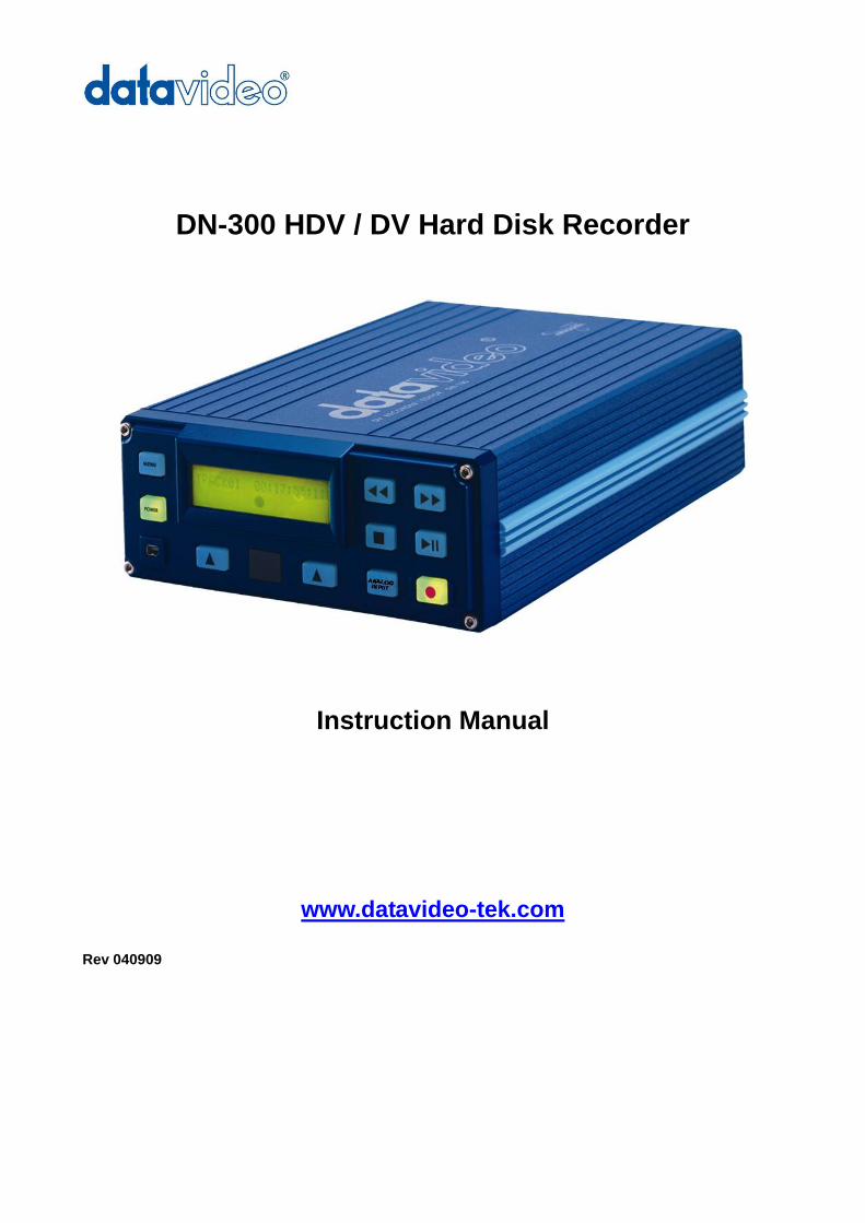
DN-300 HDV / DV Hard Disk Recorder
Instruction Manual
www.datavideo-tek.com
Rev 040909
2
Contents
Warnings and Precautions ................................................................................................................................. 3 Warranty ............................................................................................................................................................ 4 Disposal ............................................................................................................................................................. 4 Packing List ....................................................................................................................................................... 5 Introduction ........................................................................................................................................................ 5
Features ......................................................................................................................................................... 5 Connections & Controls ..................................................................................................................................... 6
Front Panel ..................................................................................................................................................... 6 Rear Panel ..................................................................................................................................................... 7
Powering On ...................................................................................................................................................... 8 Menu Options .................................................................................................................................................... 8
HDD Mode Menu ........................................................................................................................................... 9 Record Formats Menu ................................................................................................................................. 10 Input Video Standard Menu.......................................................................................................................... 10 NTSC Setup Level Menu .............................................................................................................................. 11 Video Input Source Menu............................................................................................................................. 12 GPI Mode & Functions Menu ....................................................................................................................... 12 Set Date & Time Menu ................................................................................................................................. 13 Set Full Syt Menu ......................................................................................................................................... 14 Format Hard Disk Menu ............................................................................................................................... 15 Erase Track Menu ........................................................................................................................................ 15 Convert DV to AVI Menu .............................................................................................................................. 16 Set Output Channel Menu ........................................................................................................................... 17 Scan HDD Surface Menu ............................................................................................................................. 17
Operation with a DV Camcorder / Deck / Vision Mixer .................................................................................... 18 Recording a DV track ................................................................................................................................... 18 Playing back a DV Track .............................................................................................................................. 19
Operation with a HDV Camcorder / Deck ........................................................................................................ 20 Recording a HDV (.M2T) track ..................................................................................................................... 20 Playing back an M2T (HDV) Track ............................................................................................................... 21
Operation with an Analogue Video Source ...................................................................................................... 21 Recording a (.DV) track from an Analogue input ......................................................................................... 21
Connecting to a Computer ............................................................................................................................... 22 Connecting to a PC ...................................................................................................................................... 23 Connecting to a MAC ................................................................................................................................... 25
DV File Converter Software ............................................................................................................................. 26 Installation .................................................................................................................................................... 26 Registration .................................................................................................................................................. 27 Operation ..................................................................................................................................................... 28
RS 422 Command Set / Protocol .................................................................................................................... 31 Interface Overview ....................................................................................................................................... 31 Command Block Format .............................................................................................................................. 31 Connector Pin Assignment ........................................................................................................................... 32 Communication Protocol .............................................................................................................................. 32 Command Table (without Checksum byte) .................................................................................................. 33 Detailed Description of Commands (without Checksum byte)..................................................................... 33 Return Data (without Checksum byte) ......................................................................................................... 34 Status Return Data ....................................................................................................................................... 34 RS 422 Version History ................................................................................................................................ 34 DN-300 Firmware Version ............................................................................................................................ 34
Specifications ................................................................................................................................................... 35 Supported Video Formats: ........................................................................................................................ 35 Supported File Formats: ........................................................................................................................... 35
Service and Support ........................................................................................................................................ 36
3
Warnings and Precautions 1. Read all of these warnings and save them for later reference.
2. Follow all warnings and instructions marked on this unit.
3. Unplug this unit from the wall outlet before cleaning. Do not use liquid or aerosol cleaners. Use a
damp cloth for cleaning.
4. Do not use this unit in or near water.
5. Do not place this unit on an unstable cart, stand, or table. The unit may fall, causing serious damage.
6. Slots and openings on the cabinet top, back, and bottom are provided for ventilation. To ensure safe
and reliable operation of this unit, and to protect it from overheating, do not block or cover these
openings. Do not place this unit on a bed, sofa, rug, or similar surface, as the ventilation openings on
the bottom of the cabinet will be blocked. This unit should never be placed near or over a heat
register or radiator. This unit should not be placed in a built-in installation unless proper ventilation is
provided.
7. This product should only be operated from the type of power source indicated on the marking label
of the AC adapter. If you are not sure of the type of power available, consult your Datavideo dealer or
your local power company.
8. Do not allow anything to rest on the power cord. Do not locate this unit where the power cord will be
walked on, rolled over, or otherwise stressed.
9. If an extension cord must be used with this unit, make sure that the total of the ampere ratings on the
products plugged into the extension cord do not exceed the extension cord’s rating.
10. Make sure that the total amperes of all the units that are plugged into a single wall outlet do not
exceed 15 amperes.
11. Never push objects of any kind into this unit through the cabinet ventilation slots, as they may touch
dangerous voltage points or short out parts that could result in risk of fire or electric shock. Never
spill liquid of any kind onto or into this unit.
12. Except as specifically explained elsewhere in this manual, do not attempt to service this product
yourself. Opening or removing covers that are marked “Do Not Remove” may expose you to
dangerous voltage points or other risks, and will void your warranty. Refer all service issues to
qualified service personnel.
13. Unplug this product from the wall outlet and refer to qualified service personnel under the following
conditions:
a. When the power cord is damaged or frayed;
b. When liquid has spilled into the unit;
c. When the product has been exposed to rain or water;
d. When the product does not operate normally under normal operating conditions. Adjust only
those controls that are covered by the operating instructions in this manual; improper
adjustment of other controls may result in damage to the unit and may often require
extensive work by a qualified technician to restore the unit to normal operation;
e. When the product has been dropped or the cabinet has been damaged;
f. When the product exhibits a distinct change in performance, indicating a need for service.
To avoid any possible static damage to your equipment please ensure your camcorder / deck is switched off when connecting or disconnecting the IEEE-1394 cable.
4
Warranty Datavideo warrants that the equipment it manufactures shall be free from defects in material and workmanship for a period of 12 months from the date of product purchased. If equipment fails due to such defects, Datavideo will, at its option, repair or provide a replacement for the defective part or product. Equipment that fails after the warranty period, has been operated or installed in a manner other than that specified by Datavideo, or has been subjected to abuse or modification, will be repaired for time and material charges at the Buyer’s expense. This warranty does not affect your statutory rights within the Country of purchase.
Disposal For EU Customers only - WEEE Marking.
This symbol on the product indicates that it will not be treated as household waste. It must be handed over to the applicable take-back scheme for the recycling of electrical and electronic equipment. For more detailed information about the recycling of this product, please contact your local Datavideo office.
5
Packing List The following items should be included in the box. If any items are missing please contact your supplier. 1 x DN-300 HDV / DV Hard Disk Recorder 1 x File Converter Software CD 1 x 6 Pin to 6 Pin DV Cable 2m 1 x 6 Pin to 4 Pin DV Cable 2m 1 x YUV Component I/O Cable Sub D 15 Pin Socket to 7 x BNC Socket 30cm 2 x BNC to BNC Cable 1.2m 1 x 2 Phono Plug to 2 Phono Plug Audio Cable 1.2m 1 x S-Video Plug to Plug Cable 1.2m 1 x Mains Cable 1 x Power Supply (12V 4.2A) 1 x Instruction Manual
Introduction The Datavideo DN-300 is a HDV / DV Hard Drive Recorder. It can record HDV via the IEEE-1394 (iLink, FireWire) output from HDV Camcorders (.m2t), or DV25 from DV or Analogue video sources (.dv). The DN-300 can be used as an external firewire drive from which files can be dragged and dropped to a PC or MAC. The DN-300 has a built in utility to convert .dv files to .avi files, and is also supplied with DV file converter software to create other file formats such Quicktime. Features Stand Alone DV / HDV Hard Drive Recorder / Player. Records DV from Digital or Analogue Video Inputs (DV25 via IEEE-1394 (iLink FireWire) or Component (YPbPr) / S-Video (Y/C) / Composite (CVBS) analogue video inputs). Records HDV (.m2t) via IEEE-1394 (iLink, FireWire). Full VTR playback functionality, including loop playback. RS-422 control GPI input Drag and Drop file transfer to PC or MAC via IEEE-1394. N.B. The DN-300 cannot be operated as a DV Device from a PC - The AVC Command set is not supported.
6
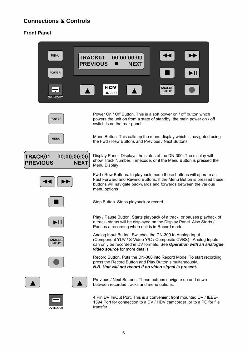
Connections & Controls Front Panel
Power On / Off Button. This is a soft power on / off button which powers the unit on from a state of standby; the main power on / off switch is on the rear panel
Menu Button. This calls up the menu display which is navigated using the Fwd / Rew Buttons and Previous / Next Buttons
Display Panel. Displays the status of the DN-300. The display will show Track Number, Timecode, or if the Menu Button is pressed the Menu Display
Fwd / Rew Buttons. In playback mode these buttons will operate as Fast Forward and Rewind Buttons. If the Menu Button is pressed these buttons will navigate backwards and forwards between the various menu options
Stop Button. Stops playback or record.
Play / Pause Button. Starts playback of a track, or pauses playback of a track- status will be displayed on the Display Panel. Also Starts / Pauses a recording when unit is in Record mode
Analog Input Button. Switches the DN-300 to Analog Input (Component YUV / S-Video Y/C / Composite CVBS) - Analog Inputs can only be recorded in DV formats. See Operation with an analogue video source for more details
Record Button. Puts the DN-300 into Record Mode. To start recording press the Record Button and Play Button simultaneously. N.B. Unit will not record if no video signal is present.
Previous / Next Buttons. These buttons navigate up and down between recorded tracks and menu options.
4 Pin DV In/Out Port. This is a convenient front mounted DV / IEEE-1394 Port for connection to a DV / HDV camcorder, or to a PC for file transfer.
7
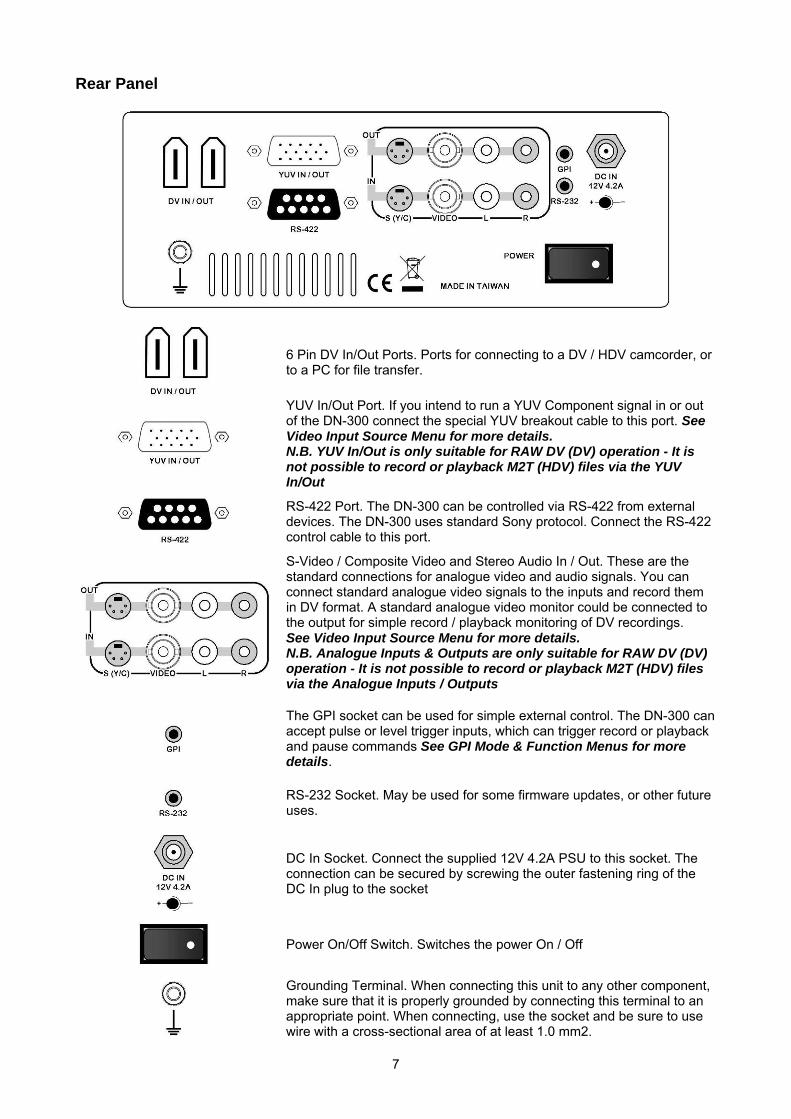
Rear Panel
6 Pin DV In/Out Ports. Ports for connecting to a DV / HDV camcorder, or to a PC for file transfer.
YUV In/Out Port. If you intend to run a YUV Component signal in or out of the DN-300 connect the special YUV breakout cable to this port. See Video Input Source Menu for more details. N.B. YUV In/Out is only suitable for RAW DV (DV) operation - It is not possible to record or playback M2T (HDV) files via the YUV In/Out
RS-422 Port. The DN-300 can be controlled via RS-422 from external devices. The DN-300 uses standard Sony protocol. Connect the RS-422 control cable to this port.
S-Video / Composite Video and Stereo Audio In / Out. These are the standard connections for analogue video and audio signals. You can connect standard analogue video signals to the inputs and record them in DV format. A standard analogue video monitor could be connected to the output for simple record / playback monitoring of DV recordings. See Video Input Source Menu for more details. N.B. Analogue Inputs & Outputs are only suitable for RAW DV (DV) operation - It is not possible to record or playback M2T (HDV) files via the Analogue Inputs / Outputs
The GPI socket can be used for simple external control. The DN-300 can accept pulse or level trigger inputs, which can trigger record or playback and pause commands See GPI Mode & Function Menus for more details.
RS-232 Socket. May be used for some firmware updates, or other future uses.
DC In Socket. Connect the supplied 12V 4.2A PSU to this socket. The connection can be secured by screwing the outer fastening ring of the DC In plug to the socket
Power On/Off Switch. Switches the power On / Off
Grounding Terminal. When connecting this unit to any other component, make sure that it is properly grounded by connecting this terminal to an appropriate point. When connecting, use the socket and be sure to use wire with a cross-sectional area of at least 1.0 mm2.
8
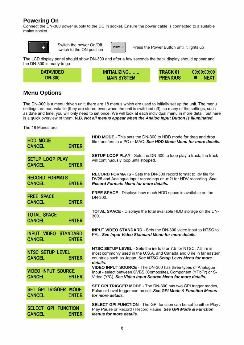
Powering On Connect the DN-300 power supply to the DC In socket. Ensure the power cable is connected to a suitable mains socket.
Switch the power On/Off switch to the ON position
Press the Power Button until it lights up
The LCD display panel should show DN-300 and after a few seconds the track display should appear and the DN-300 is ready to go
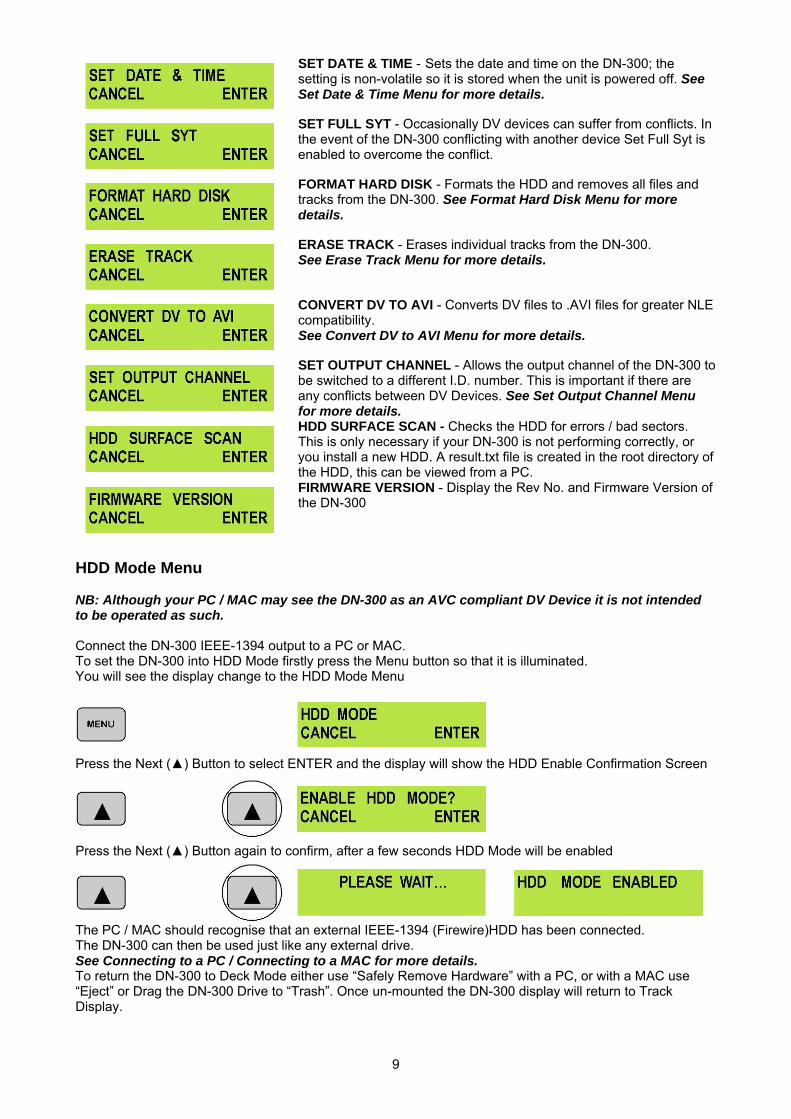
Menu Options The DN-300 is a menu driven unit; there are 18 menus which are used to initially set up the unit. The menu settings are non-volatile (they are stored even when the unit is switched off), so many of the settings, such as date and time, you will only need to set once. We will look at each individual menu in more detail, but here is a quick overview of them. N.B. Not all menus appear when the Analog Input Button is illuminated. The 18 Menus are:
HDD MODE - This sets the DN-300 to HDD mode for drag and drop file transfers to a PC or MAC. See HDD Mode Menu for more details.
SETUP LOOP PLAY - Sets the DN-300 to loop play a track, the track will continuously loop until stopped.
RECORD FORMATS - Sets the DN-300 record format to .dv file for DV25 and Analogue input recordings or .m2t for HDV recording. See Record Formats Menu for more details.
FREE SPACE - Displays how much HDD space is available on the DN-300.
TOTAL SPACE - Displays the total available HDD storage on the DN-300.
INPUT VIDEO STANDARD - Sets the DN-300 video input to NTSC to PAL. See Input Video Standard Menu for more details.
NTSC SETUP LEVEL - Sets the ire to 0 or 7.5 for NTSC. 7.5 ire is most commonly used in the U.S.A. and Canada and 0 ire in far eastern countries such as Japan. See NTSC Setup Level Menu for more details.
VIDEO INPUT SOURCE - The DN-300 has three types of Analogue Input - select between CVBS (Composite), Component (YPbPr) or S-Video (Y/C). See Video Input Source Menu for more details.
SET GPI TRIGGER MODE - The DN-300 has two GPI trigger modes, Pulse or Level trigger can be set. See GPI Mode & Function Menus for more details.
SELECT GPI FUNCTION - The GPI function can be set to either Play / Play Pause or Record / Record Pause. See GPI Mode & Function Menus for more details.
9
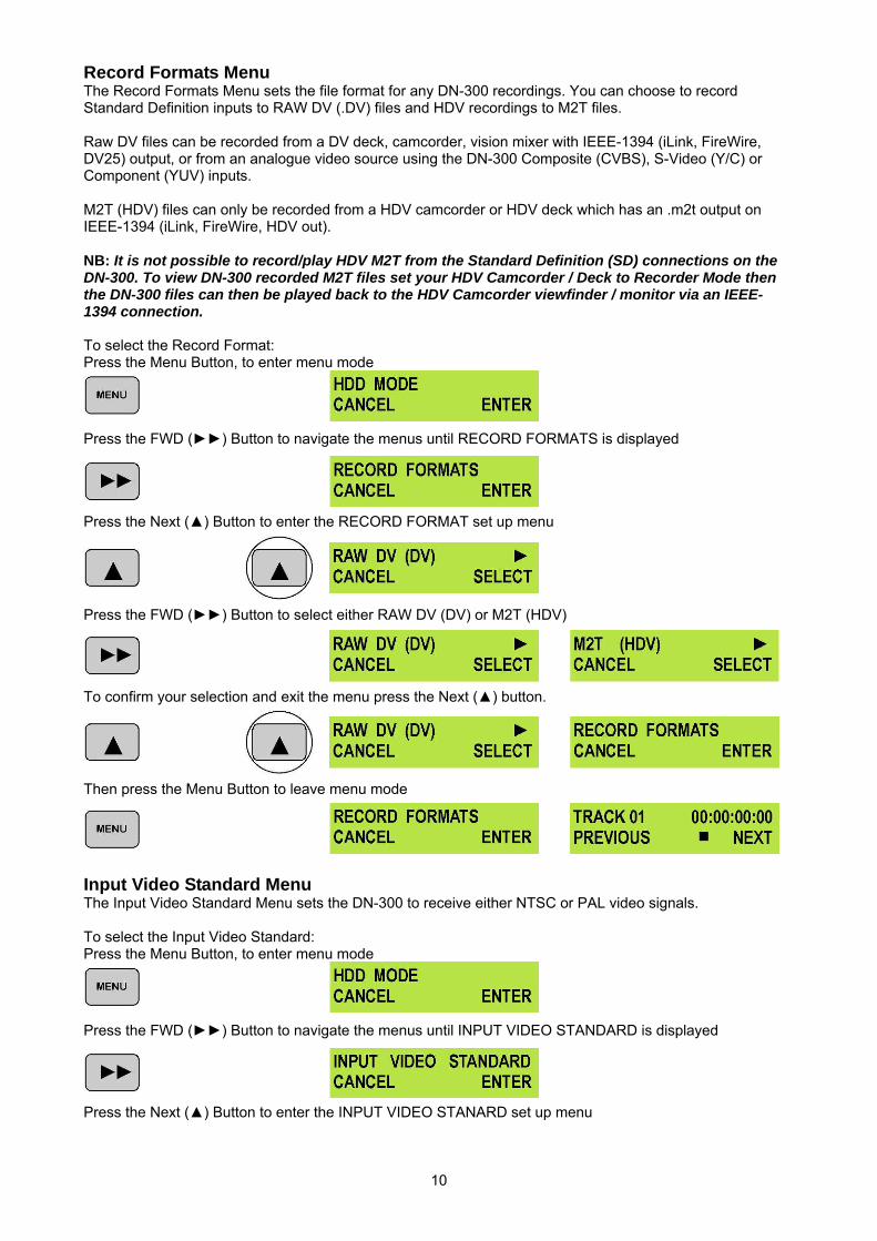
SET DATE & TIME - Sets the date and time on the DN-300; the setting is non-volatile so it is stored when the unit is powered off. See Set Date & Time Menu for more details.
SET FULL SYT - Occasionally DV devices can suffer from conflicts. In the event of the DN-300 conflicting with another device Set Full Syt is enabled to overcome the conflict.
FORMAT HARD DISK - Formats the HDD and removes all files and tracks from the DN-300. See Format Hard Disk Menu for more details.
ERASE TRACK - Erases individual tracks from the DN-300. See Erase Track Menu for more details.
CONVERT DV TO AVI - Converts DV files to .AVI files for greater NLE compatibility. See Convert DV to AVI Menu for more details.
SET OUTPUT CHANNEL - Allows the output channel of the DN-300 to be switched to a different I.D. number. This is important if there are any conflicts between DV Devices. See Set Output Channel Menu for more details.
HDD SURFACE SCAN - Checks the HDD for errors / bad sectors. This is only necessary if your DN-300 is not performing correctly, or you install a new HDD. A result.txt file is created in the root directory of the HDD, this can be viewed from a PC.
FIRMWARE VERSION - Display the Rev No. and Firmware Version of the DN-300
HDD Mode Menu NB: Although your PC / MAC may see the DN-300 as an AVC compliant DV Device it is not intended to be operated as such. Connect the DN-300 IEEE-1394 output to a PC or MAC. To set the DN-300 into HDD Mode firstly press the Menu button so that it is illuminated. You will see the display change to the HDD Mode Menu
Press the Next () Button to select ENTER and the display will show the HDD Enable Confirmation Screen
Press the Next () Button again to confirm, after a few seconds HDD Mode will be enabled
The PC / MAC should recognise that an external IEEE-1394 (Firewire)HDD has been connected. The DN-300 can then be used just like any external drive. See Connecting to a PC / Connecting to a MAC for more details. To return the DN-300 to Deck Mode either use “Safely Remove Hardware” with a PC, or with a MAC use “Eject” or Drag the DN-300 Drive to “Trash”. Once un-mounted the DN-300 display will return to Track Display.
10
Record Formats Menu The Record Formats Menu sets the file format for any DN-300 recordings. You can choose to record Standard Definition inputs to RAW DV (.DV) files and HDV recordings to M2T files. Raw DV files can be recorded from a DV deck, camcorder, vision mixer with IEEE-1394 (iLink, FireWire, DV25) output, or from an analogue video source using the DN-300 Composite (CVBS), S-Video (Y/C) or Component (YUV) inputs. M2T (HDV) files can only be recorded from a HDV camcorder or HDV deck which has an .m2t output on IEEE-1394 (iLink, FireWire, HDV out). NB: It is not possible to record/play HDV M2T from the Standard Definition (SD) connections on the DN-300. To view DN-300 recorded M2T files set your HDV Camcorder / Deck to Recorder Mode then the DN-300 files can then be played back to the HDV Camcorder viewfinder / monitor via an IEEE-1394 connection. To select the Record Format: Press the Menu Button, to enter menu mode
Press the FWD () Button to navigate the menus until RECORD FORMATS is displayed
Press the Next () Button to enter the RECORD FORMAT set up menu
Press the FWD () Button to select either RAW DV (DV) or M2T (HDV)
To confirm your selection and exit the menu press the Next () button.
Then press the Menu Button to leave menu mode
Input Video Standard Menu The Input Video Standard Menu sets the DN-300 to receive either NTSC or PAL video signals. To select the Input Video Standard: Press the Menu Button, to enter menu mode
Press the FWD () Button to navigate the menus until INPUT VIDEO STANDARD is displayed
Press the Next () Button to enter the INPUT VIDEO STANARD set up menu
11
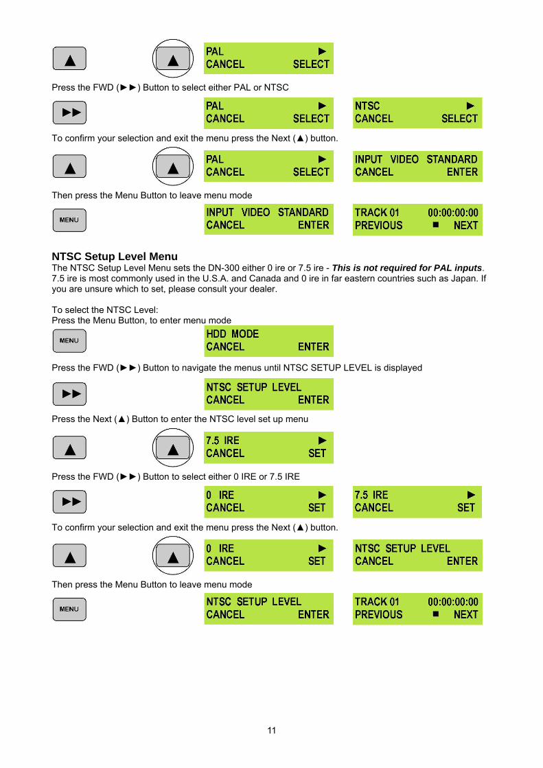
Press the FWD () Button to select either PAL or NTSC
To confirm your selection and exit the menu press the Next () button.
Then press the Menu Button to leave menu mode
NTSC Setup Level Menu The NTSC Setup Level Menu sets the DN-300 either 0 ire or 7.5 ire - This is not required for PAL inputs. 7.5 ire is most commonly used in the U.S.A. and Canada and 0 ire in far eastern countries such as Japan. If you are unsure which to set, please consult your dealer. To select the NTSC Level: Press the Menu Button, to enter menu mode
Press the FWD () Button to navigate the menus until NTSC SETUP LEVEL is displayed
Press the Next () Button to enter the NTSC level set up menu
Press the FWD () Button to select either 0 IRE or 7.5 IRE
To confirm your selection and exit the menu press the Next () button.
Then press the Menu Button to leave menu mode
12
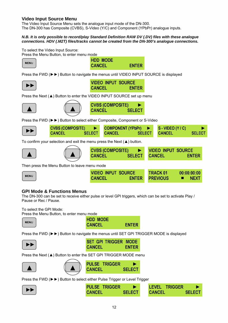
Video Input Source Menu The Video Input Source Menu sets the analogue input mode of the DN-300. The DN-300 has Composite (CVBS), S-Video (Y/C) and Component (YPbPr) analogue inputs. N.B. It is only possible to record/play Standard Definition RAW DV (.DV) files with these analogue connections. HDV (.M2T) files/tracks cannot be created from the DN-300’s analogue connections. To select the Video Input Source: Press the Menu Button, to enter menu mode
Press the FWD () Button to navigate the menus until VIDEO INPUT SOURCE is displayed
Press the Next () Button to enter the VIDEO INPUT SOURCE set up menu
Press the FWD () Button to select either Composite, Component or S-Video
To confirm your selection and exit the menu press the Next () button.
Then press the Menu Button to leave menu mode
GPI Mode & Functions Menus The DN-300 can be set to receive either pulse or level GPI triggers, which can be set to activate Play / Pause or Rec / Pause. To select the GPI Mode: Press the Menu Button, to enter menu mode
Press the FWD () Button to navigate the menus until SET GPI TRIGGER MODE is displayed
Press the Next () Button to enter the SET GPI TRIGGER MODE menu
Press the FWD () Button to select either Pulse Trigger or Level Trigger
13
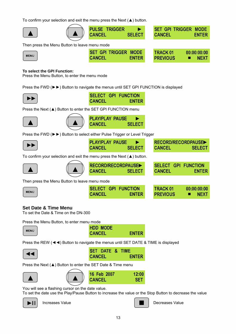
To confirm your selection and exit the menu press the Next () button.
Then press the Menu Button to leave menu mode
To select the GPI Function: Press the Menu Button, to enter the menu mode
Press the FWD () Button to navigate the menus until SET GPI FUNCTION is displayed
Press the Next () Button to enter the SET GPI FUNCTION menu
Press the FWD () Button to select either Pulse Trigger or Level Trigger
To confirm your selection and exit the menu press the Next () button.
Then press the Menu Button to leave menu mode
Set Date & Time Menu To set the Date & Time on the DN-300 Press the Menu Button, to enter menu mode
Press the REW () Button to navigate the menus until SET DATE & TIME is displayed
Press the Next () Button to enter the SET Date & Time menu
You will see a flashing cursor on the date value. To set the date use the Play/Pause Button to increase the value or the Stop Button to decrease the value
Increases Value Decreases Value
14
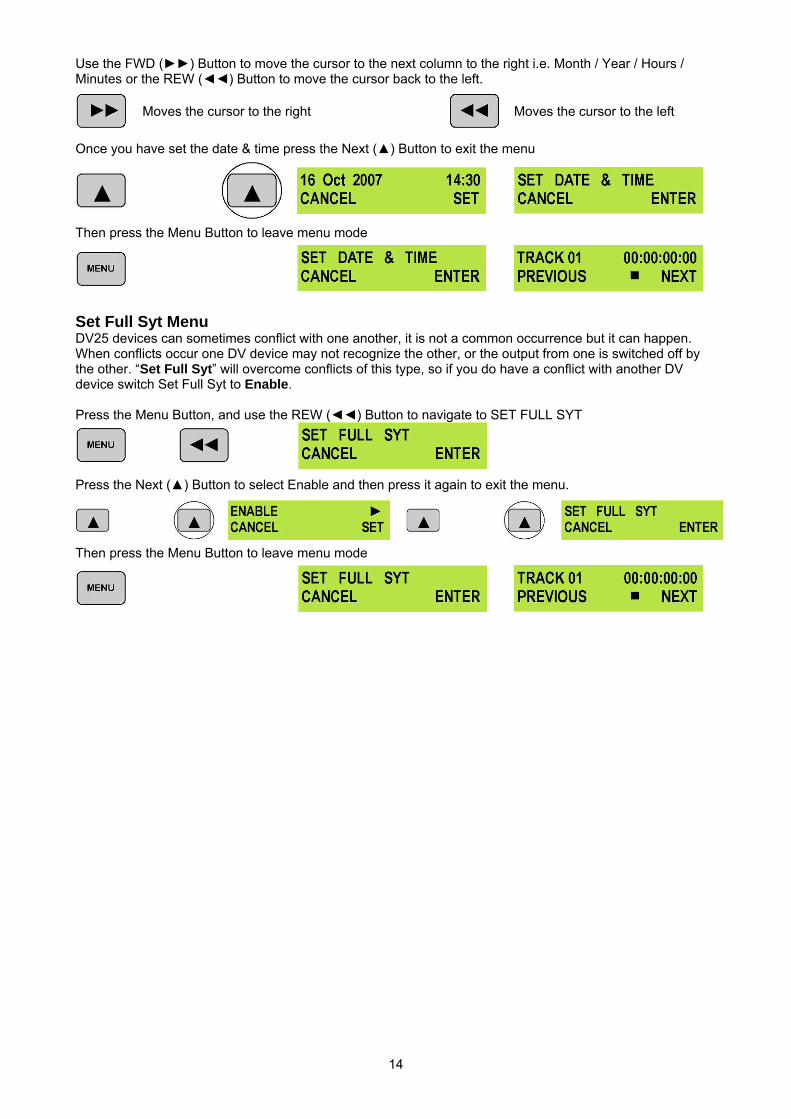
Use the FWD () Button to move the cursor to the next column to the right i.e. Month / Year / Hours / Minutes or the REW () Button to move the cursor back to the left.
Moves the cursor to the right Moves the cursor to the left
Once you have set the date & time press the Next () Button to exit the menu
Then press the Menu Button to leave menu mode
Set Full Syt Menu DV25 devices can sometimes conflict with one another, it is not a common occurrence but it can happen. When conflicts occur one DV device may not recognize the other, or the output from one is switched off by the other. “Set Full Syt” will overcome conflicts of this type, so if you do have a conflict with another DV device switch Set Full Syt to Enable. Press the Menu Button, and use the REW () Button to navigate to SET FULL SYT
Press the Next () Button to select Enable and then press it again to exit the menu.
Then press the Menu Button to leave menu mode
15
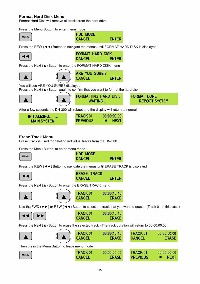
Format Hard Disk Menu Format Hard Disk will remove all tracks from the hard drive. Press the Menu Button, to enter menu mode
Press the REW () Button to navigate the menus until FORMAT HARD DISK is displayed
Press the Next () Button to enter the FORMAT HARD DISK menu
You will see ARE YOU SURE? displayed Press the Next () Button again to confirm that you want to format the hard disk.
After a few seconds the DN-300 will reboot and the display will return to normal
Erase Track Menu Erase Track is used for deleting individual tracks from the DN-300. Press the Menu Button, to enter menu mode
Press the REW () Button to navigate the menus until ERASE TRACK is displayed
Press the Next () Button to enter the ERASE TRACK menu
Use the FWD () or REW () Button to select the track that you want to erase - (Track 01 in this case)
Press the Next () Button to erase the selected track - The track duration will return to 00:00:00:00
Then press the Menu Button to leave menu mode
16
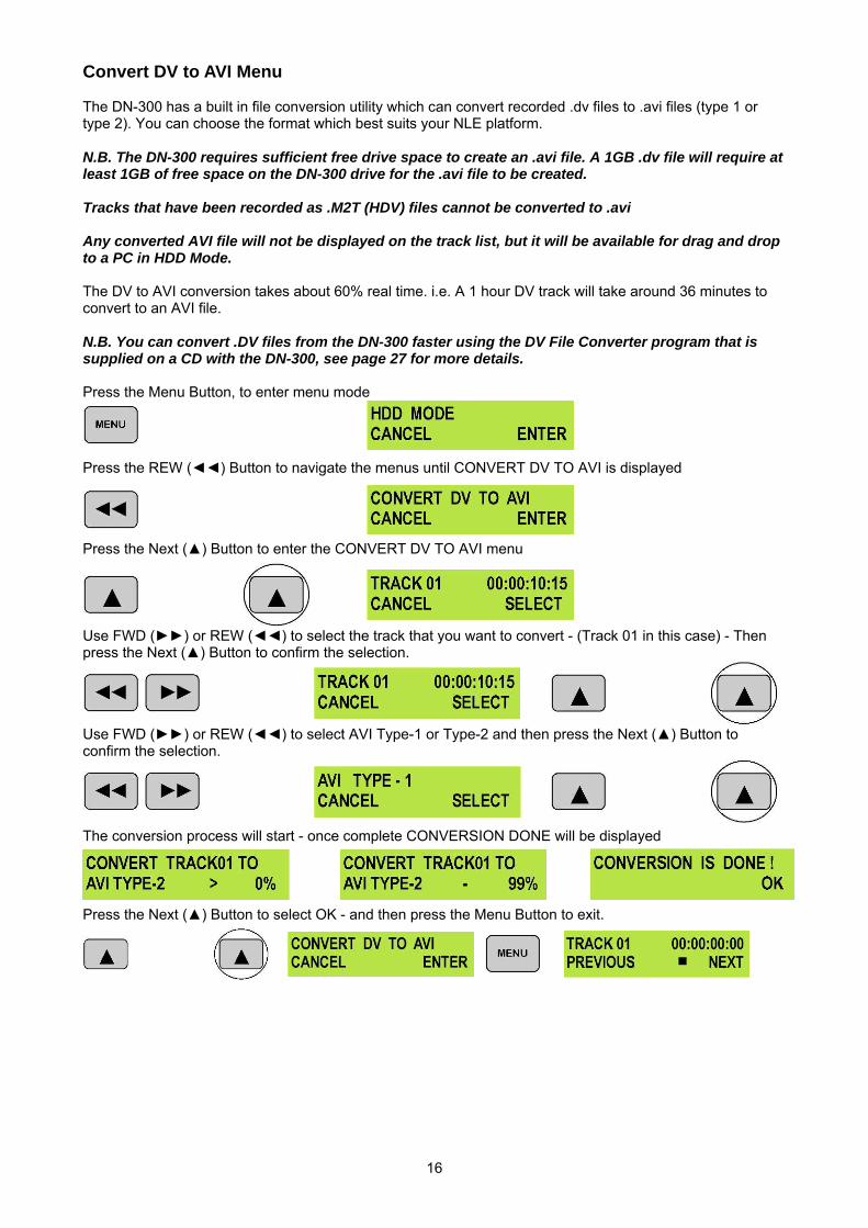
Convert DV to AVI Menu The DN-300 has a built in file conversion utility which can convert recorded .dv files to .avi files (type 1 or type 2). You can choose the format which best suits your NLE platform. N.B. The DN-300 requires sufficient free drive space to create an .avi file. A 1GB .dv file will require at least 1GB of free space on the DN-300 drive for the .avi file to be created. Tracks that have been recorded as .M2T (HDV) files cannot be converted to .avi Any converted AVI file will not be displayed on the track list, but it will be available for drag and drop to a PC in HDD Mode. The DV to AVI conversion takes about 60% real time. i.e. A 1 hour DV track will take around 36 minutes to convert to an AVI file. N.B. You can convert .DV files from the DN-300 faster using the DV File Converter program that is supplied on a CD with the DN-300, see page 27 for more details. Press the Menu Button, to enter menu mode
Press the REW () Button to navigate the menus until CONVERT DV TO AVI is displayed
Press the Next () Button to enter the CONVERT DV TO AVI menu
Use FWD () or REW () to select the track that you want to convert - (Track 01 in this case) - Then press the Next () Button to confirm the selection.
Use FWD () or REW () to select AVI Type-1 or Type-2 and then press the Next () Button to confirm the selection.
The conversion process will start - once complete CONVERSION DONE will be displayed
Press the Next () Button to select OK - and then press the Menu Button to exit.
17
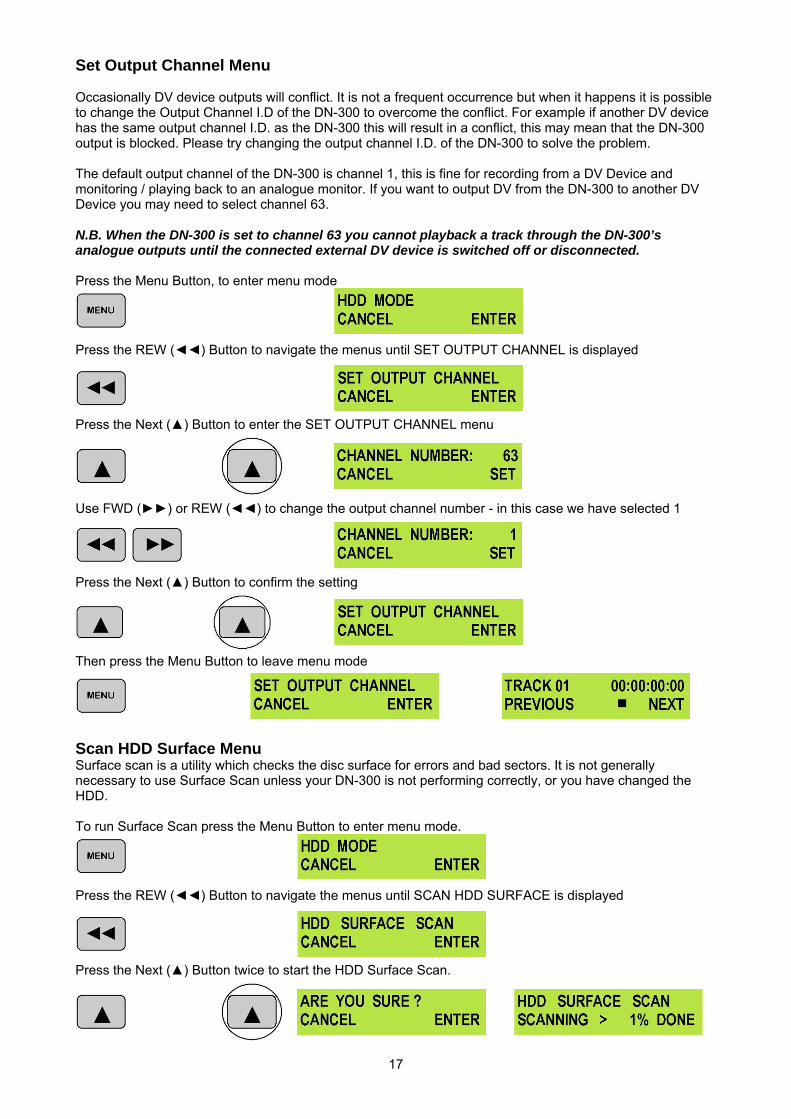
Set Output Channel Menu Occasionally DV device outputs will conflict. It is not a frequent occurrence but when it happens it is possible to change the Output Channel I.D of the DN-300 to overcome the conflict. For example if another DV device has the same output channel I.D. as the DN-300 this will result in a conflict, this may mean that the DN-300 output is blocked. Please try changing the output channel I.D. of the DN-300 to solve the problem. The default output channel of the DN-300 is channel 1, this is fine for recording from a DV Device and monitoring / playing back to an analogue monitor. If you want to output DV from the DN-300 to another DV Device you may need to select channel 63. N.B. When the DN-300 is set to channel 63 you cannot playback a track through the DN-300’s analogue outputs until the connected external DV device is switched off or disconnected. Press the Menu Button, to enter menu mode
Press the REW () Button to navigate the menus until SET OUTPUT CHANNEL is displayed
Press the Next () Button to enter the SET OUTPUT CHANNEL menu
Use FWD () or REW () to change the output channel number - in this case we have selected 1
Press the Next () Button to confirm the setting
Then press the Menu Button to leave menu mode
Scan HDD Surface Menu Surface scan is a utility which checks the disc surface for errors and bad sectors. It is not generally necessary to use Surface Scan unless your DN-300 is not performing correctly, or you have changed the HDD. To run Surface Scan press the Menu Button to enter menu mode.
Press the REW () Button to navigate the menus until SCAN HDD SURFACE is displayed
Press the Next () Button twice to start the HDD Surface Scan.
18
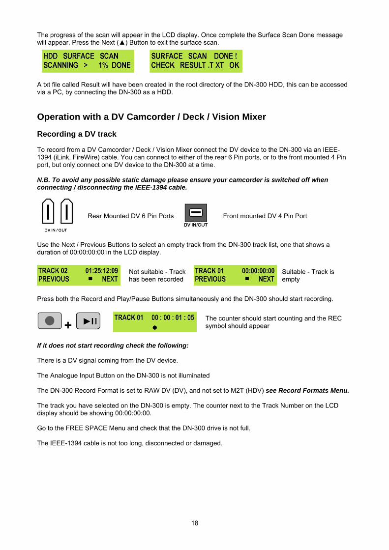
The progress of the scan will appear in the LCD display. Once complete the Surface Scan Done message will appear. Press the Next () Button to exit the surface scan.
A txt file called Result will have been created in the root directory of the DN-300 HDD, this can be accessed via a PC, by connecting the DN-300 as a HDD.
Operation with a DV Camcorder / Deck / Vision Mixer Recording a DV track To record from a DV Camcorder / Deck / Vision Mixer connect the DV device to the DN-300 via an IEEE-1394 (iLink, FireWire) cable. You can connect to either of the rear 6 Pin ports, or to the front mounted 4 Pin port, but only connect one DV device to the DN-300 at a time. N.B. To avoid any possible static damage please ensure your camcorder is switched off when connecting / disconnecting the IEEE-1394 cable.
Rear Mounted DV 6 Pin Ports
Front mounted DV 4 Pin Port
Use the Next / Previous Buttons to select an empty track from the DN-300 track list, one that shows a duration of 00:00:00:00 in the LCD display.
Not suitable - Track has been recorded
Suitable - Track is empty
Press both the Record and Play/Pause Buttons simultaneously and the DN-300 should start recording.
+
The counter should start counting and the REC symbol should appear
If it does not start recording check the following: There is a DV signal coming from the DV device. The Analogue Input Button on the DN-300 is not illuminated The DN-300 Record Format is set to RAW DV (DV), and not set to M2T (HDV) see Record Formats Menu. The track you have selected on the DN-300 is empty. The counter next to the Track Number on the LCD display should be showing 00:00:00:00. Go to the FREE SPACE Menu and check that the DN-300 drive is not full. The IEEE-1394 cable is not too long, disconnected or damaged.
19
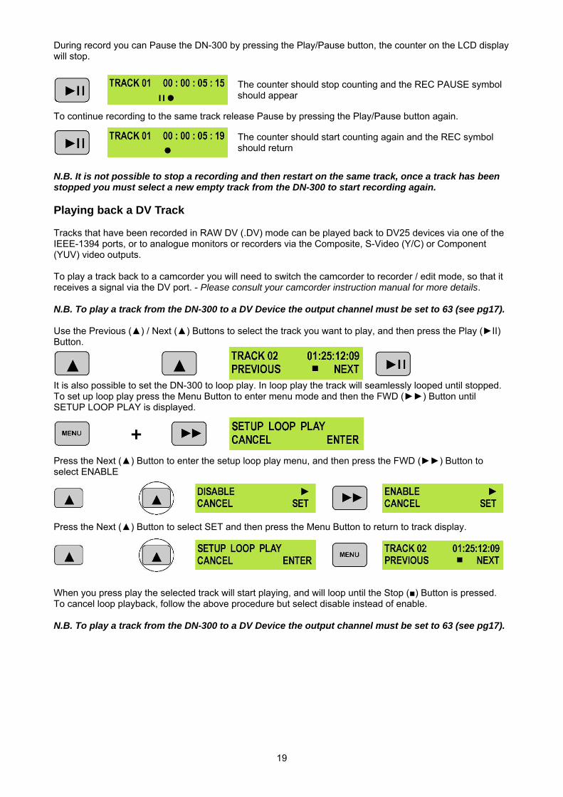
During record you can Pause the DN-300 by pressing the Play/Pause button, the counter on the LCD display will stop.
The counter should stop counting and the REC PAUSE symbol should appear
To continue recording to the same track release Pause by pressing the Play/Pause button again.
The counter should start counting again and the REC symbol should return
N.B. It is not possible to stop a recording and then restart on the same track, once a track has been stopped you must select a new empty track from the DN-300 to start recording again. Playing back a DV Track Tracks that have been recorded in RAW DV (.DV) mode can be played back to DV25 devices via one of the IEEE-1394 ports, or to analogue monitors or recorders via the Composite, S-Video (Y/C) or Component (YUV) video outputs. To play a track back to a camcorder you will need to switch the camcorder to recorder / edit mode, so that it receives a signal via the DV port. - Please consult your camcorder instruction manual for more details. N.B. To play a track from the DN-300 to a DV Device the output channel must be set to 63 (see pg17). Use the Previous () / Next () Buttons to select the track you want to play, and then press the Play (II) Button.
It is also possible to set the DN-300 to loop play. In loop play the track will seamlessly looped until stopped. To set up loop play press the Menu Button to enter menu mode and then the FWD () Button until SETUP LOOP PLAY is displayed.
+ Press the Next () Button to enter the setup loop play menu, and then press the FWD () Button to select ENABLE
Press the Next () Button to select SET and then press the Menu Button to return to track display.
When you press play the selected track will start playing, and will loop until the Stop () Button is pressed. To cancel loop playback, follow the above procedure but select disable instead of enable. N.B. To play a track from the DN-300 to a DV Device the output channel must be set to 63 (see pg17).
20
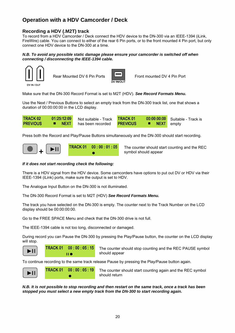
Operation with a HDV Camcorder / Deck Recording a HDV (.M2T) track To record from a HDV Camcorder / Deck connect the HDV device to the DN-300 via an IEEE-1394 (iLink, FireWire) cable. You can connect to either of the rear 6 Pin ports, or to the front mounted 4 Pin port, but only connect one HDV device to the DN-300 at a time. N.B. To avoid any possible static damage please ensure your camcorder is switched off when connecting / disconnecting the IEEE-1394 cable.
Rear Mounted DV 6 Pin Ports
Front mounted DV 4 Pin Port
Make sure that the DN-300 Record Format is set to M2T (HDV). See Record Formats Menu. Use the Next / Previous Buttons to select an empty track from the DN-300 track list, one that shows a duration of 00:00:00:00 in the LCD display.
Not suitable - Track has been recorded
Suitable - Track is empty
Press both the Record and Play/Pause Buttons simultaneously and the DN-300 should start recording.
+
The counter should start counting and the REC symbol should appear
If it does not start recording check the following: There is a HDV signal from the HDV device. Some camcorders have options to put out DV or HDV via their IEEE-1394 (iLink) ports, make sure the output is set to HDV. The Analogue Input Button on the DN-300 is not illuminated. The DN-300 Record Format is set to M2T (HDV) See Record Formats Menu. The track you have selected on the DN-300 is empty. The counter next to the Track Number on the LCD display should be 00:00:00:00. Go to the FREE SPACE Menu and check that the DN-300 drive is not full. The IEEE-1394 cable is not too long, disconnected or damaged. During record you can Pause the DN-300 by pressing the Play/Pause button, the counter on the LCD display will stop.
The counter should stop counting and the REC PAUSE symbol should appear
To continue recording to the same track release Pause by pressing the Play/Pause button again.
The counter should start counting again and the REC symbol should return
N.B. It is not possible to stop recording and then restart on the same track, once a track has been stopped you must select a new empty track from the DN-300 to start recording again.
21
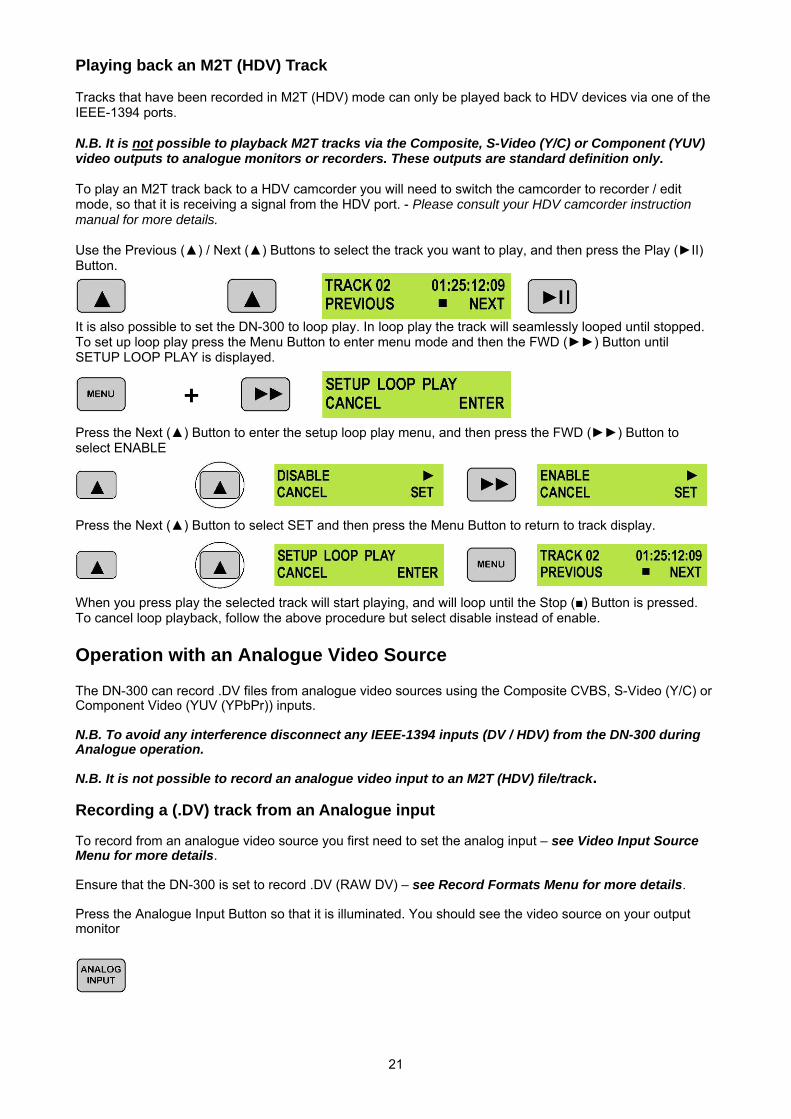
Playing back an M2T (HDV) Track Tracks that have been recorded in M2T (HDV) mode can only be played back to HDV devices via one of the IEEE-1394 ports. N.B. It is not possible to playback M2T tracks via the Composite, S-Video (Y/C) or Component (YUV) video outputs to analogue monitors or recorders. These outputs are standard definition only. To play an M2T track back to a HDV camcorder you will need to switch the camcorder to recorder / edit mode, so that it is receiving a signal from the HDV port. - Please consult your HDV camcorder instruction manual for more details. Use the Previous () / Next () Buttons to select the track you want to play, and then press the Play (II) Button.
It is also possible to set the DN-300 to loop play. In loop play the track will seamlessly looped until stopped. To set up loop play press the Menu Button to enter menu mode and then the FWD () Button until SETUP LOOP PLAY is displayed.
+ Press the Next () Button to enter the setup loop play menu, and then press the FWD () Button to select ENABLE
Press the Next () Button to select SET and then press the Menu Button to return to track display.
When you press play the selected track will start playing, and will loop until the Stop () Button is pressed. To cancel loop playback, follow the above procedure but select disable instead of enable. Operation with an Analogue Video Source The DN-300 can record .DV files from analogue video sources using the Composite CVBS, S-Video (Y/C) or Component Video (YUV (YPbPr)) inputs. N.B. To avoid any interference disconnect any IEEE-1394 inputs (DV / HDV) from the DN-300 during Analogue operation. N.B. It is not possible to record an analogue video input to an M2T (HDV) file/track. Recording a (.DV) track from an Analogue input To record from an analogue video source you first need to set the analog input – see Video Input Source Menu for more details. Ensure that the DN-300 is set to record .DV (RAW DV) – see Record Formats Menu for more details. Press the Analogue Input Button so that it is illuminated. You should see the video source on your output monitor
22
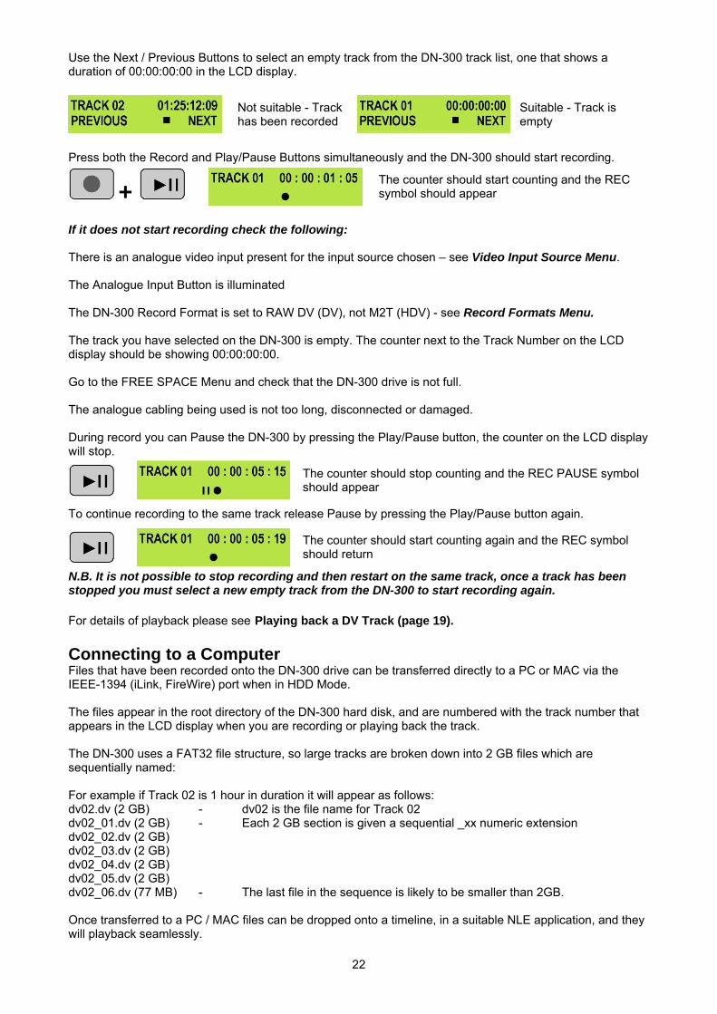
Use the Next / Previous Buttons to select an empty track from the DN-300 track list, one that shows a duration of 00:00:00:00 in the LCD display.
Not suitable - Track has been recorded
Suitable - Track is empty
Press both the Record and Play/Pause Buttons simultaneously and the DN-300 should start recording.
+
The counter should start counting and the REC symbol should appear
If it does not start recording check the following: There is an analogue video input present for the input source chosen – see Video Input Source Menu. The Analogue Input Button is illuminated The DN-300 Record Format is set to RAW DV (DV), not M2T (HDV) - see Record Formats Menu. The track you have selected on the DN-300 is empty. The counter next to the Track Number on the LCD display should be showing 00:00:00:00. Go to the FREE SPACE Menu and check that the DN-300 drive is not full. The analogue cabling being used is not too long, disconnected or damaged. During record you can Pause the DN-300 by pressing the Play/Pause button, the counter on the LCD display will stop.
The counter should stop counting and the REC PAUSE symbol should appear
To continue recording to the same track release Pause by pressing the Play/Pause button again.
The counter should start counting again and the REC symbol should return
N.B. It is not possible to stop recording and then restart on the same track, once a track has been stopped you must select a new empty track from the DN-300 to start recording again. For details of playback please see Playing back a DV Track (page 19). Connecting to a Computer Files that have been recorded onto the DN-300 drive can be transferred directly to a PC or MAC via the IEEE-1394 (iLink, FireWire) port when in HDD Mode. The files appear in the root directory of the DN-300 hard disk, and are numbered with the track number that appears in the LCD display when you are recording or playing back the track. The DN-300 uses a FAT32 file structure, so large tracks are broken down into 2 GB files which are sequentially named: For example if Track 02 is 1 hour in duration it will appear as follows: dv02.dv (2 GB) - dv02 is the file name for Track 02 dv02_01.dv (2 GB) - Each 2 GB section is given a sequential _xx numeric extension dv02_02.dv (2 GB) dv02_03.dv (2 GB) dv02_04.dv (2 GB) dv02_05.dv (2 GB) dv02_06.dv (77 MB) - The last file in the sequence is likely to be smaller than 2GB. Once transferred to a PC / MAC files can be dropped onto a timeline, in a suitable NLE application, and they will playback seamlessly.
23
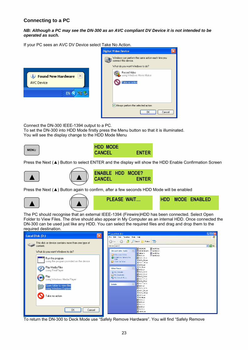
Connecting to a PC NB: Although a PC may see the DN-300 as an AVC compliant DV Device it is not intended to be operated as such. If your PC sees an AVC DV Device select Take No Action.
Connect the DN-300 IEEE-1394 output to a PC. To set the DN-300 into HDD Mode firstly press the Menu button so that it is illuminated. You will see the display change to the HDD Mode Menu
Press the Next () Button to select ENTER and the display will show the HDD Enable Confirmation Screen
Press the Next () Button again to confirm, after a few seconds HDD Mode will be enabled
The PC should recognise that an external IEEE-1394 (Firewire)HDD has been connected. Select Open Folder to View Files. The drive should also appear in My Computer as an internal HDD. Once connected the DN-300 can be used just like any HDD. You can select the required files and drag and drop them to the required destination.
To return the DN-300 to Deck Mode use “Safely Remove Hardware”. You will find “Safely Remove
24
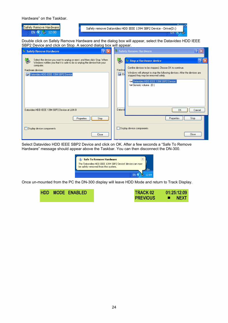
Hardware” on the Taskbar.
Double click on Safely Remove Hardware and the dialog box will appear, select the Datavideo HDD IEEE SBP2 Device and click on Stop. A second dialog box will appear.
Select Datavideo HDD IEEE SBP2 Device and click on OK. After a few seconds a “Safe To Remove Hardware” message should appear above the Taskbar. You can then disconnect the DN-300.
Once un-mounted from the PC the DN-300 display will leave HDD Mode and return to Track Display.
25
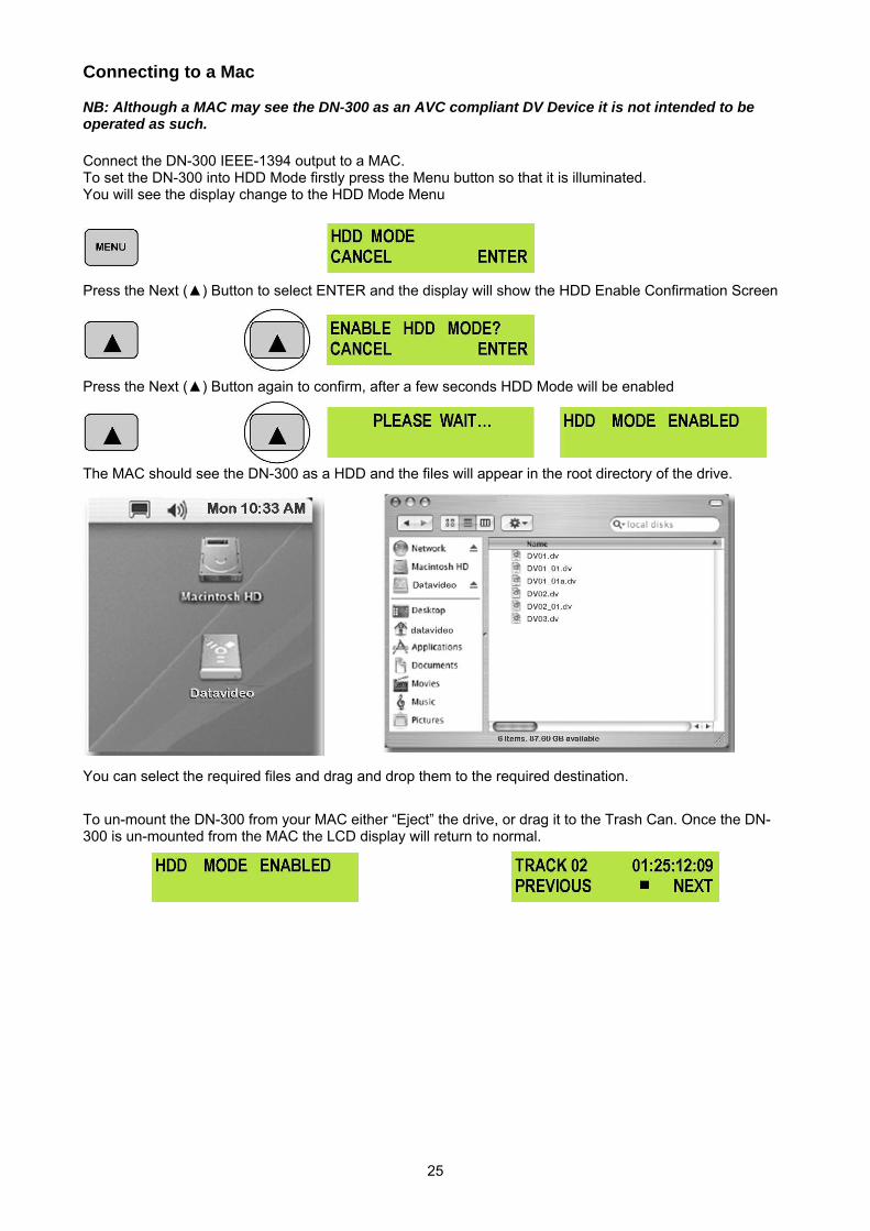
Connecting to a Mac NB: Although a MAC may see the DN-300 as an AVC compliant DV Device it is not intended to be operated as such. Connect the DN-300 IEEE-1394 output to a MAC. To set the DN-300 into HDD Mode firstly press the Menu button so that it is illuminated. You will see the display change to the HDD Mode Menu
Press the Next () Button to select ENTER and the display will show the HDD Enable Confirmation Screen
Press the Next () Button again to confirm, after a few seconds HDD Mode will be enabled
The MAC should see the DN-300 as a HDD and the files will appear in the root directory of the drive.
You can select the required files and drag and drop them to the required destination.
To un-mount the DN-300 from your MAC either “Eject” the drive, or drag it to the Trash Can. Once the DN-300 is un-mounted from the MAC the LCD display will return to normal.
26
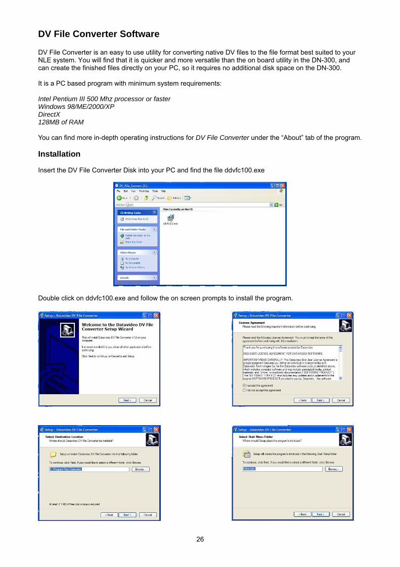
DV File Converter Software DV File Converter is an easy to use utility for converting native DV files to the file format best suited to your NLE system. You will find that it is quicker and more versatile than the on board utility in the DN-300, and can create the finished files directly on your PC, so it requires no additional disk space on the DN-300. It is a PC based program with minimum system requirements: Intel Pentium III 500 Mhz processor or faster Windows 98/ME/2000/XP DirectX 128MB of RAM You can find more in-depth operating instructions for DV File Converter under the “About” tab of the program. Installation Insert the DV File Converter Disk into your PC and find the file ddvfc100.exe
Double click on ddvfc100.exe and follow the on screen prompts to install the program.
27
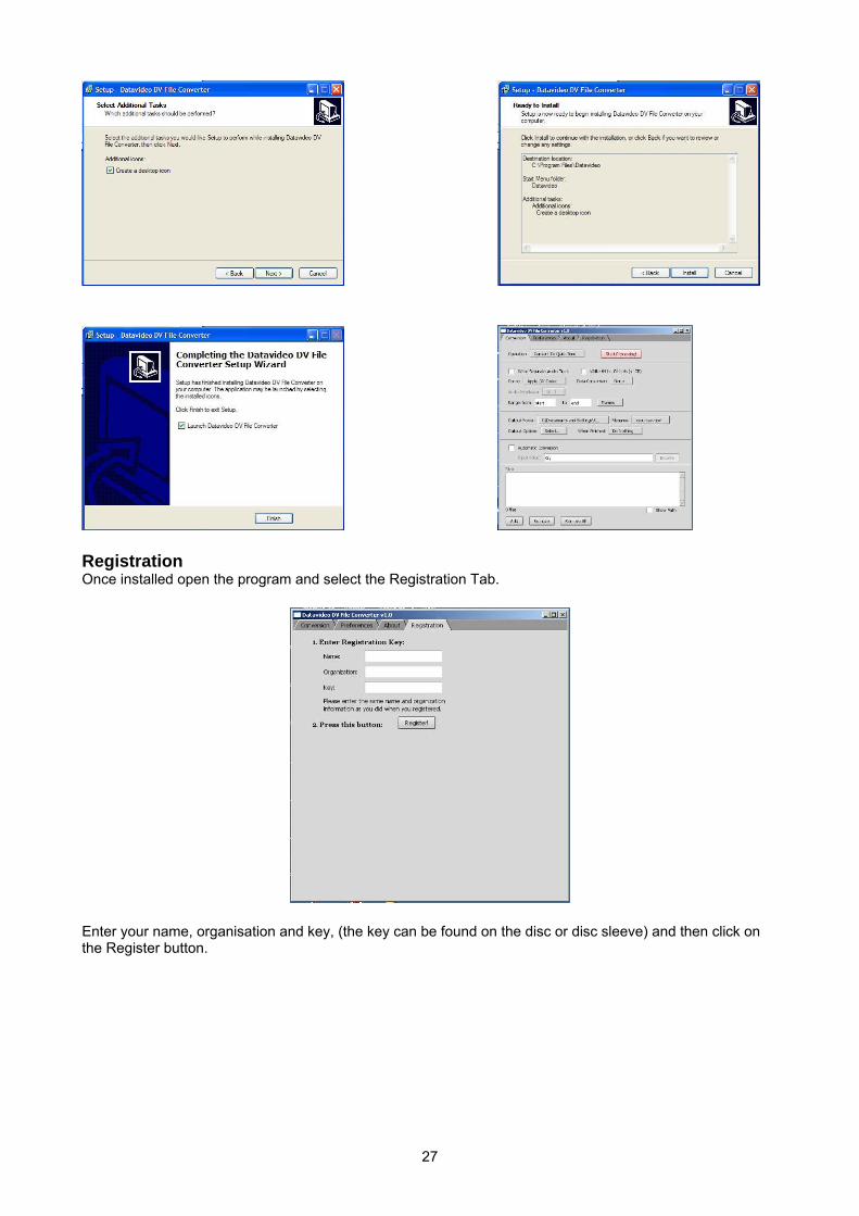
Registration Once installed open the program and select the Registration Tab.
Enter your name, organisation and key, (the key can be found on the disc or disc sleeve) and then click on the Register button.
28
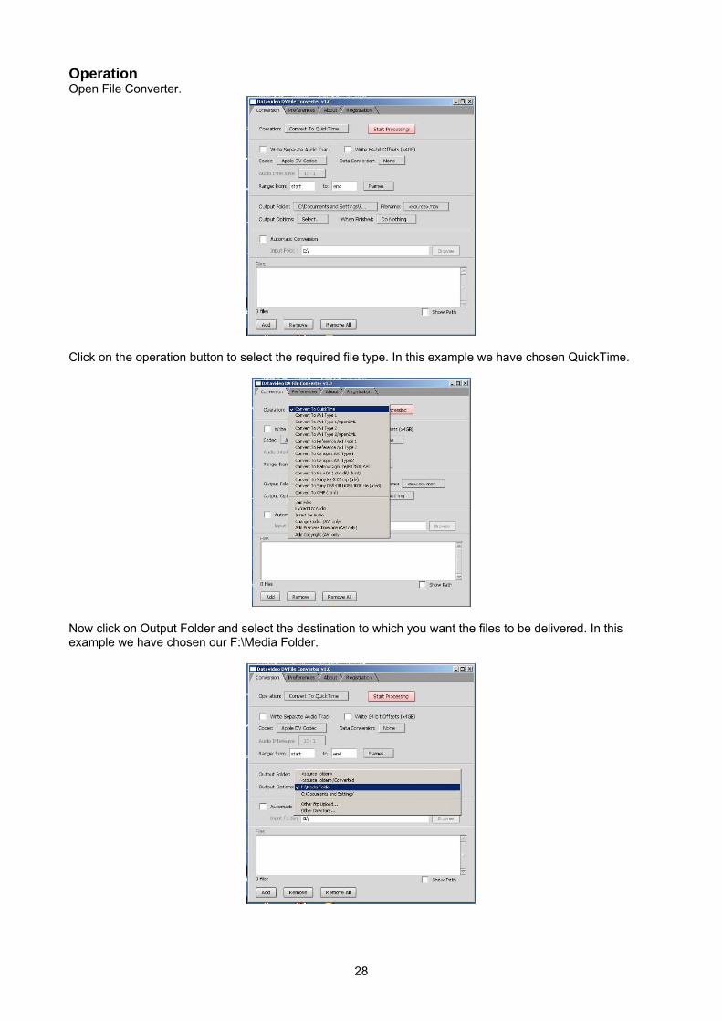
Operation Open File Converter.
Click on the operation button to select the required file type. In this example we have chosen QuickTime.
Now click on Output Folder and select the destination to which you want the files to be delivered. In this example we have chosen our F:\Media Folder.
29
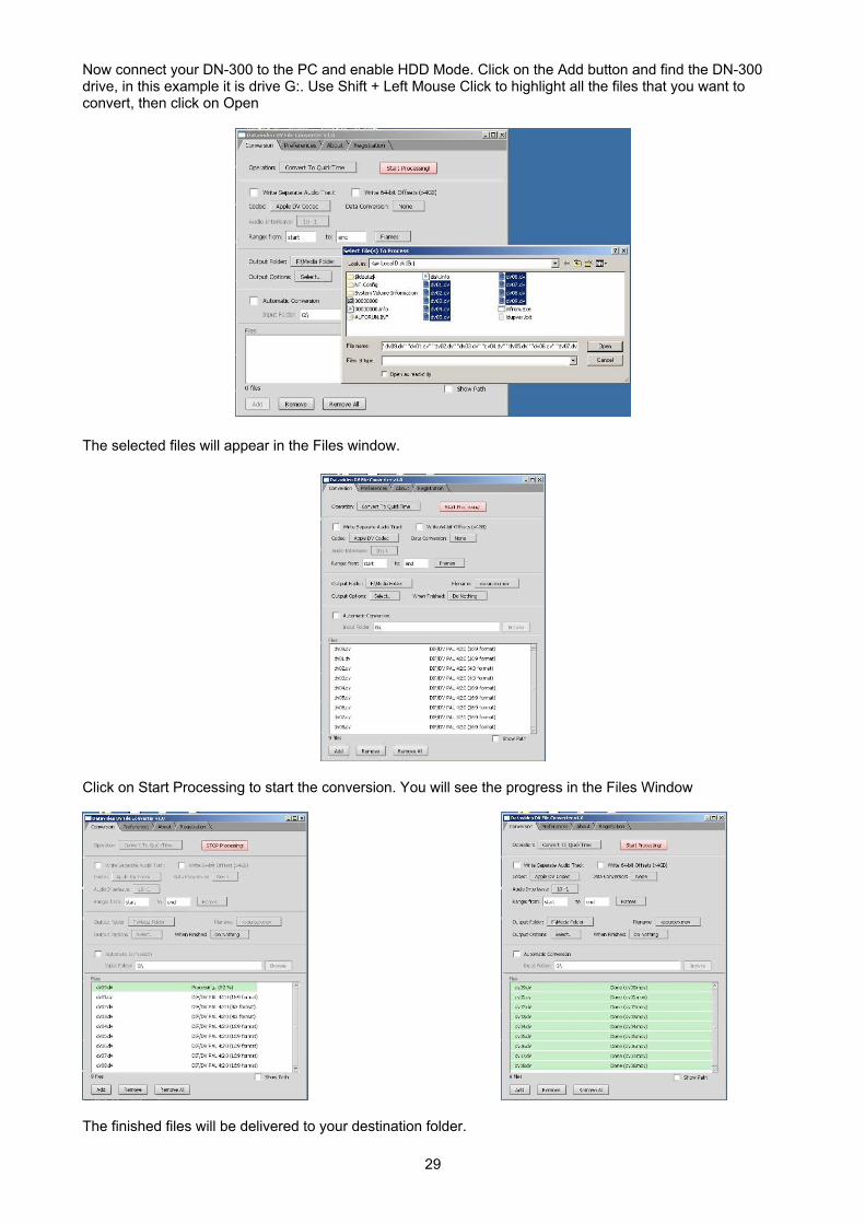
Now connect your DN-300 to the PC and enable HDD Mode. Click on the Add button and find the DN-300 drive, in this example it is drive G:. Use Shift + Left Mouse Click to highlight all the files that you want to convert, then click on Open
The selected files will appear in the Files window.
Click on Start Processing to start the conversion. You will see the progress in the Files Window
The finished files will be delivered to your destination folder.
30
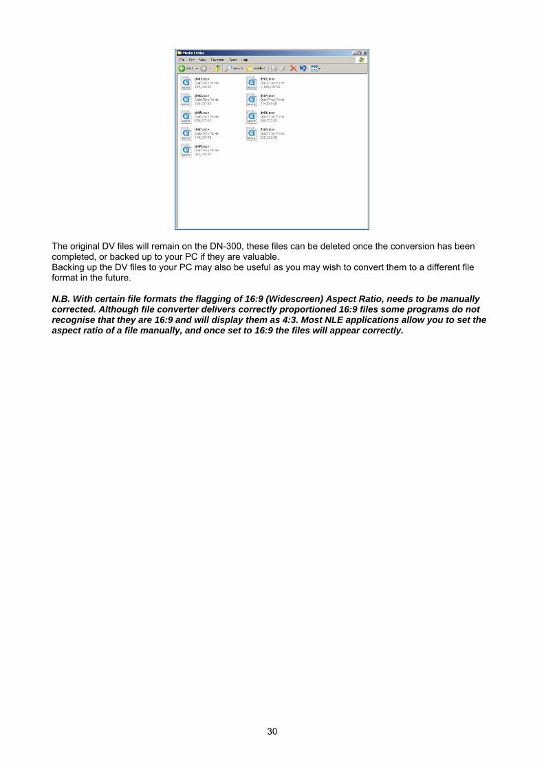
The original DV files will remain on the DN-300, these files can be deleted once the conversion has been completed, or backed up to your PC if they are valuable. Backing up the DV files to your PC may also be useful as you may wish to convert them to a different file format in the future. N.B. With certain file formats the flagging of 16:9 (Widescreen) Aspect Ratio, needs to be manually corrected. Although file converter delivers correctly proportioned 16:9 files some programs do not recognise that they are 16:9 and will display them as 4:3. Most NLE applications allow you to set the aspect ratio of a file manually, and once set to 16:9 the files will appear correctly.
31
RS 422 Command Set / Protocol Interface Overview
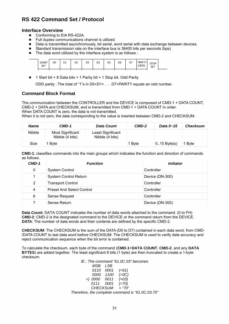
Conforming to EIA RS-422A. Full duplex communications channel is utilized. Data is transmitted asynchronously, bit serial, word serial with data exchange between devices. Standard transmission rate on the interface bus is 38400 bits per seconds (bps) The data word utilized by the interface system is as follows :
1 Start bit + 8 Data bits + 1 Parity bit + 1 Stop bit. Odd Parity
ODD parity : The total of “1”s in D0+D1+ . . . D7+PARITY equals an odd number. Command Block Format The communication between the CONTROLLER and the DEVICE is composed of CMD-1 + DATA COUNT, CMD-2 + DATA and CHECKSUM, and is transmitted from CMD-1 + DATA COUNT in order. When DATA COUNT is zero, the data is not transmitted. When it is not zero, the data corresponding to the value is inserted between CMD-2 and CHECKSUM.
Name CMD-1 Data Count CMD-2 Data 0~15 Checksum
Nibble Most Significant Nibble (4 bits)
Least Significant Nibble (4 bits)
Size 1 Byte 1 Byte 0..15 Byte(s) 1 Byte
CMD-1: classifies commands into the main groups which indicates the function and direction of commands as follows.
CMD-1 Function Initiator
0 System Control Controller
1 System Control Return Device (DN-300)
2 Transport Control Controller
4 Preset And Select Control Controller
6 Sense Request Controller
7 Sense Return Device (DN-300)
Data Count: DATA COUNT indicates the number of data words attached to the command. (0 to FH) CMD-2: CMD-2 is the designated command to the DEVICE or the command return from the DEVICE. DATA: The number of data words and their contents are defined by the specific CMD-2. CHECKSUM: The CHECKSUM is the sum of the DATA (D0 to D7) contained in each data word, from CMD-/DATA COUNT to last data word before CHECKSUM. The CHECKSUM is used to verify data accuracy and reject communication sequence when the bit error is contained. To calculate the checksum, each byte of the command (CMD-1+DATA COUNT, CMD-2, and any DATA BYTES) are added together. The least significant 8 bits (1 byte) are then truncated to create a 1-byte checksum.
IE.: The command “61.0C.03” becomes MSB LSB 0110 0001 (=61) 0000 1100 (=0C)
+) 0000 0011 (=03) 0111 0001 (=70) CHECKSUM = “70”
Therefore, the complete command is “61.0C.03.70”
D0 D1 D2 D3 D4 D5 D6 D7 PARITY(ODD)
START BIT
STOP BIT
32
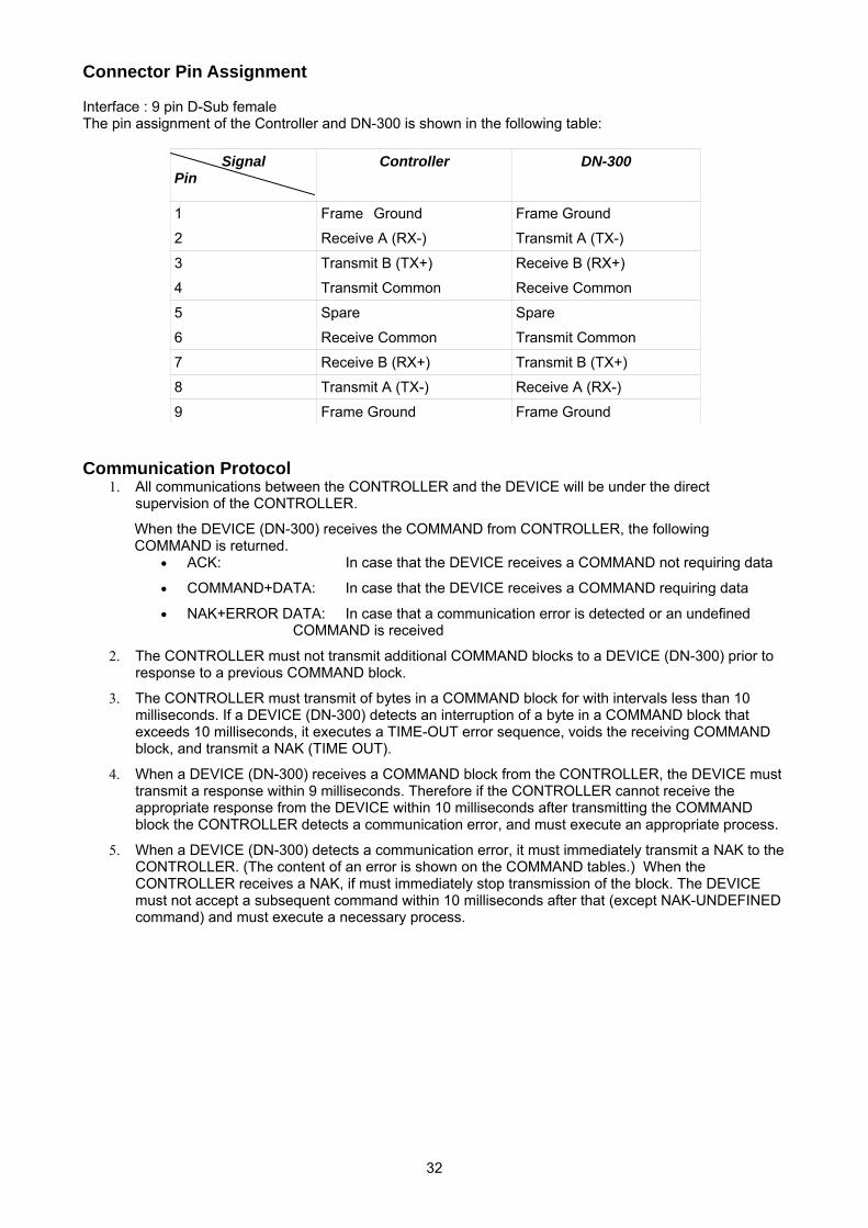
Connector Pin Assignment Interface : 9 pin D-Sub female The pin assignment of the Controller and DN-300 is shown in the following table:
Signal Pin
Controller DN-300
1 Frame Ground Frame Ground
2 Receive A (RX-) Transmit A (TX-)
3 Transmit B (TX+) Receive B (RX+)
4 Transmit Common Receive Common
5 Spare Spare
6 Receive Common Transmit Common
7 Receive B (RX+) Transmit B (TX+)
8 Transmit A (TX-) Receive A (RX-)
9 Frame Ground Frame Ground
Communication Protocol
1. All communications between the CONTROLLER and the DEVICE will be under the direct supervision of the CONTROLLER.
When the DEVICE (DN-300) receives the COMMAND from CONTROLLER, the following COMMAND is returned.
• ACK: In case that the DEVICE receives a COMMAND not requiring data
• COMMAND+DATA: In case that the DEVICE receives a COMMAND requiring data
• NAK+ERROR DATA: In case that a communication error is detected or an undefined COMMAND is received
2. The CONTROLLER must not transmit additional COMMAND blocks to a DEVICE (DN-300) prior to response to a previous COMMAND block.
3. The CONTROLLER must transmit of bytes in a COMMAND block for with intervals less than 10 milliseconds. If a DEVICE (DN-300) detects an interruption of a byte in a COMMAND block that exceeds 10 milliseconds, it executes a TIME-OUT error sequence, voids the receiving COMMAND block, and transmit a NAK (TIME OUT).
4. When a DEVICE (DN-300) receives a COMMAND block from the CONTROLLER, the DEVICE must transmit a response within 9 milliseconds. Therefore if the CONTROLLER cannot receive the appropriate response from the DEVICE within 10 milliseconds after transmitting the COMMAND block the CONTROLLER detects a communication error, and must execute an appropriate process.
5. When a DEVICE (DN-300) detects a communication error, it must immediately transmit a NAK to the CONTROLLER. (The content of an error is shown on the COMMAND tables.) When the CONTROLLER receives a NAK, if must immediately stop transmission of the block. The DEVICE must not accept a subsequent command within 10 milliseconds after that (except NAK-UNDEFINED command) and must execute a necessary process.
33
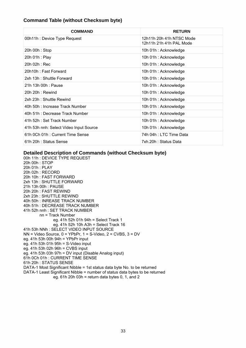
Command Table (without Checksum byte)
COMMAND RETURN
00h11h : Device Type Request 12h11h 20h 41h NTSC Mode 12h11h 21h 41h PAL Mode
20h 00h : Stop 10h 01h : Acknowledge
20h 01h : Play 10h 01h : Acknowledge
20h 02h : Rec 10h 01h : Acknowledge
20h10h : Fast Forward 10h 01h : Acknowledge
2xh 13h : Shuttle Forward 10h 01h : Acknowledge
21h 13h 00h : Pause 10h 01h : Acknowledge
20h 20h : Rewind 10h 01h : Acknowledge
2xh 23h : Shuttle Rewind 10h 01h : Acknowledge
40h 50h : Increase Track Number 10h 01h : Acknowledge
40h 51h : Decrease Track Number 10h 01h : Acknowledge
41h 52h : Set Track Number 10h 01h : Acknowledge
41h 53h nnh: Select Video Input Source 10h 01h : Acknowledge
61h 0Ch 01h : Current Time Sense 74h 04h : LTC Time Data
61h 20h : Status Sense 7xh.20h : Status Data
Detailed Description of Commands (without Checksum byte) 00h 11h : DEVICE TYPE REQUEST 20h 00h : STOP 20h 01h : PLAY 20h 02h : RECORD 20h 10h : FAST FORWARD 2xh 13h : SHUTTLE FORWARD 21h 13h 00h : PAUSE 20h 20h : FAST REWIND 2xh 23h : SHUTTLE REWIND 40h 50h : INREASE TRACK NUMBER 40h 51h : DECREASE TRACK NUMBER 41h 52h nnh : SET TRACK NUMBER
nn = Track Number eg. 41h 52h 01h 94h = Select Track 1 eg. 41h 52h 10h A3h = Select Track 16
41h 53h NNh : SELECT VIDEO INPUT SOURCE NN = Video Source, 0 = YPbPr, 1 = S-Video, 2 = CVBS, 3 = DV eg. 41h 53h 00h 94h = YPbPr input eg. 41h 53h 01h 95h = S-Video input eg. 41h 53h 02h 96h = CVBS input eg. 41h 53h 03h 97h = DV input (Disable Analog input) 61h 0Ch 01h : CURRENT TIME SENSE 61h 20h : STATUS SENSE DATA-1 Most Significant Nibble = 1st status data byte No. to be returned DATA-1 Least Significant Nibble = number of status data bytes to be returned
eg. 61h 20h 03h = return data bytes 0, 1, and 2
34
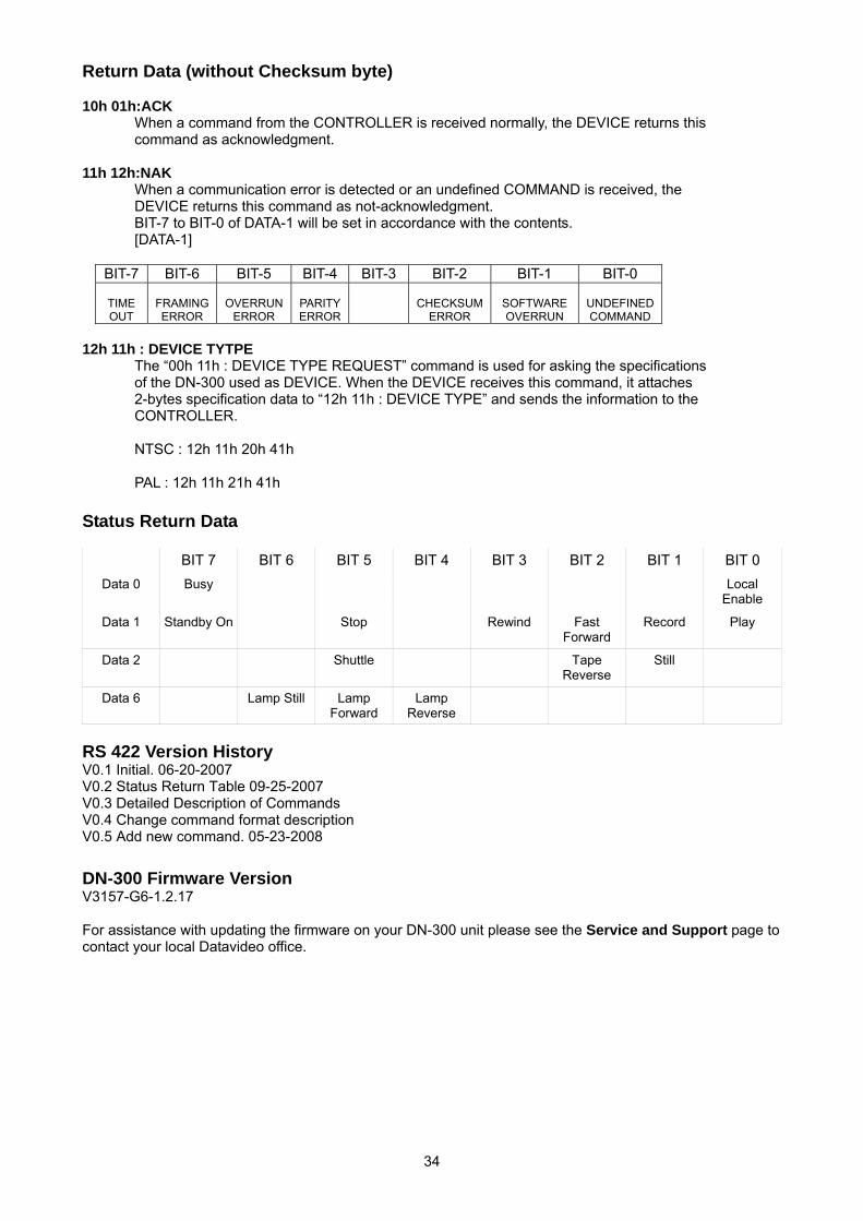
Return Data (without Checksum byte) 10h 01h:ACK
When a command from the CONTROLLER is received normally, the DEVICE returns this command as acknowledgment.
11h 12h:NAK
When a communication error is detected or an undefined COMMAND is received, the DEVICE returns this command as not-acknowledgment. BIT-7 to BIT-0 of DATA-1 will be set in accordance with the contents. [DATA-1]
BIT-7 BIT-6 BIT-5 BIT-4 BIT-3 BIT-2 BIT-1 BIT-0
TIME OUT
FRAMING ERROR
OVERRUN
ERROR
PARITY ERROR
CHECKSUM
ERROR
SOFTWARE OVERRUN
UNDEFINED COMMAND
12h 11h : DEVICE TYTPE
The “00h 11h : DEVICE TYPE REQUEST” command is used for asking the specifications of the DN-300 used as DEVICE. When the DEVICE receives this command, it attaches 2-bytes specification data to “12h 11h : DEVICE TYPE” and sends the information to the CONTROLLER. NTSC : 12h 11h 20h 41h PAL : 12h 11h 21h 41h
Status Return Data BIT 7 BIT 6 BIT 5 BIT 4 BIT 3 BIT 2 BIT 1 BIT 0
Data 0 Busy Local Enable
Data 1 Standby On Stop Rewind Fast Forward
Record Play
Data 2 Shuttle Tape Reverse
Still
Data 6 Lamp Still Lamp Forward
Lamp Reverse
RS 422 Version History V0.1 Initial. 06-20-2007 V0.2 Status Return Table 09-25-2007 V0.3 Detailed Description of Commands V0.4 Change command format description V0.5 Add new command. 05-23-2008
DN-300 Firmware Version V3157-G6-1.2.17 For assistance with updating the firmware on your DN-300 unit please see the Service and Support page to contact your local Datavideo office.
35
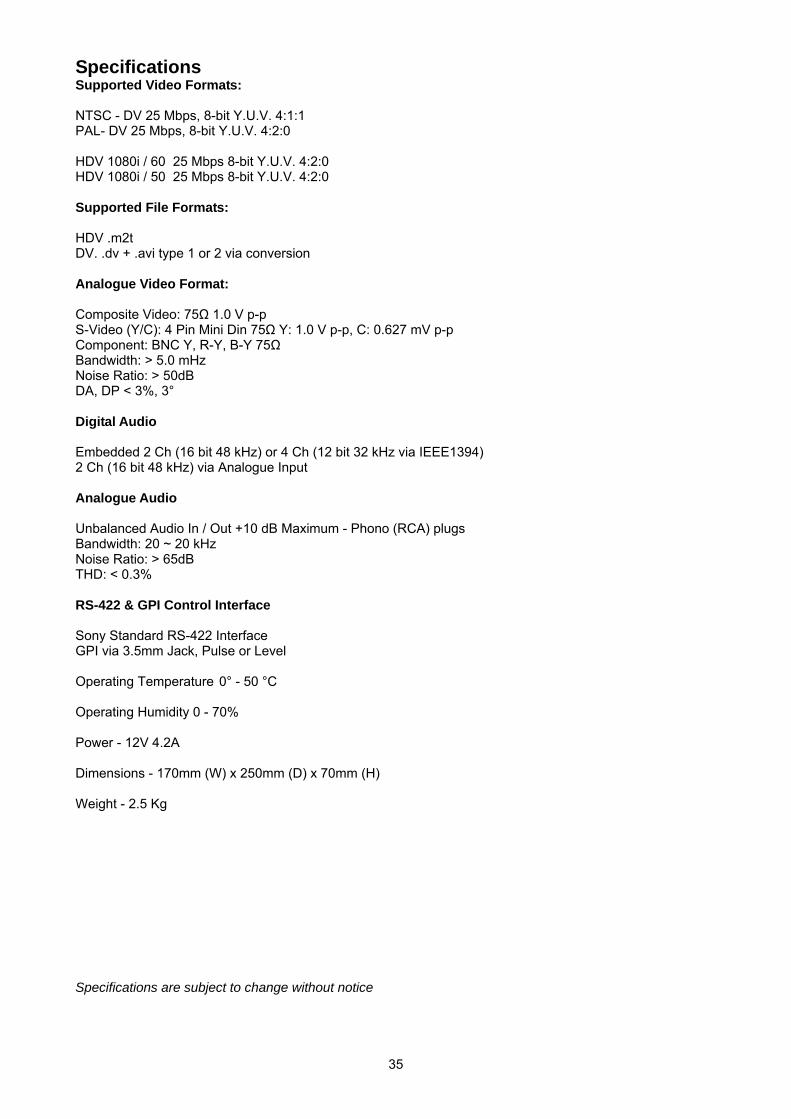
Specifications Supported Video Formats: NTSC - DV 25 Mbps, 8-bit Y.U.V. 4:1:1 PAL- DV 25 Mbps, 8-bit Y.U.V. 4:2:0 HDV 1080i / 60 25 Mbps 8-bit Y.U.V. 4:2:0 HDV 1080i / 50 25 Mbps 8-bit Y.U.V. 4:2:0 Supported File Formats: HDV .m2t DV. .dv + .avi type 1 or 2 via conversion Analogue Video Format: Composite Video: 75Ω 1.0 V p-p S-Video (Y/C): 4 Pin Mini Din 75Ω Y: 1.0 V p-p, C: 0.627 mV p-p Component: BNC Y, R-Y, B-Y 75Ω Bandwidth: > 5.0 mHz Noise Ratio: > 50dB DA, DP < 3%, 3° Digital Audio Embedded 2 Ch (16 bit 48 kHz) or 4 Ch (12 bit 32 kHz via IEEE1394) 2 Ch (16 bit 48 kHz) via Analogue Input Analogue Audio Unbalanced Audio In / Out +10 dB Maximum - Phono (RCA) plugs Bandwidth: 20 ~ 20 kHz Noise Ratio: > 65dB THD: < 0.3% RS-422 & GPI Control Interface Sony Standard RS-422 Interface GPI via 3.5mm Jack, Pulse or Level Operating Temperature 0° - 50 °C Operating Humidity 0 - 70% Power - 12V 4.2A Dimensions - 170mm (W) x 250mm (D) x 70mm (H) Weight - 2.5 Kg Specifications are subject to change without notice
36
Service and Support It is our goal to make your products ownership a satisfying experience. Our supporting staff is available to
assist you in setting up and operating your system. Please refer to our web site www.datavideo-tek.com for
answers to common questions, support requests or contact your local office below.
Datavideo Global Website: www.datavideo-tek.com
Datavideo Corporation
Tel: +1 562 696 2324 Fax: +1 562-698-6930 E-Mail: [email protected]
Datavideo Technologies Europe BV
Tel: +31-30-261-96-56 Fax: +31-30 261-96-57 E-Mail: [email protected]
Datavideo UK Limited
Tel: +44 1457 851 000 Fax: +44 1457 850 964 E-Mail: [email protected]
Datavideo Technologies Co., Ltd
Tel: +886 2 8227 2888 Fax: +886-2-8227-2777 E-mail: [email protected]
Datavideo Technologies China Co., Ltd
Tel: +86 21-5603 6599 Fax:+86 21-5603 6770 E-mail: [email protected]
Datavideo Technologies (S) PTE Ltd
Tel: +65-6749 6866 Fax: +65-6749 3266 E-mail: [email protected]
Datavideo HK Ltd
Tel: +852 2833 1981 Fax: +852-2833-9916 E-mail: [email protected]
All the trademarks are the properties of their respective owners.
Datavideo Technologies Co., Ltd. All rights reserved 2018.
P/N: ????????????????