DMRC ELECTRICAL STANDARDS & DESIGN WING … - 66-33KV, 30 45MVA... · 2.2 On Load Tap Changer for...
21
SPECIFICATIONS NO. DMES-0002 / DMRC-E-TR-TRANSF-02 - SPECIFICATIONS FOR THREE PHASE 66/33KV, 30/45MVA AUXILIARY MAIN TRANSFORMER FOR RECEIVING SUBSTATIONS Draft - 13012014 Page 1 of 21 DELHI METRO RAIL CORPORATION LIMITED DMRC ELECTRICAL STANDARDS & DESIGN WING (DESDW) SPECIFICATION NO. DMES-0002 / DMRC-E-TR-TRANSF-02 SPECIFICATIONS FOR THREE PHASE 66/33KV, 30/45MVA AUXILIARY MAIN TRANSFORMER FOR RECEIVING SUBSTATIONS Issued on: Date Stage 13 th Jan 2014 Draft DELHI METRO RAIL CORPORATION LTD. 7 th Floor, B-Wing, Metro Bhawan, Fire Brigade Lane, Barakhamba Road, New Delhi –110 001
Transcript of DMRC ELECTRICAL STANDARDS & DESIGN WING … - 66-33KV, 30 45MVA... · 2.2 On Load Tap Changer for...
SPECIFICATIONS NO. DMES-0002 / DMRC-E-TR-TRANSF-02 - SPECIFICATIONS FOR THREE PHASE 66/33KV, 30/45MVA AUXILIARY MAIN TRANSFORMER FOR RECEIVING SUBSTATIONS Draft - 13012014
Page 1 of 21
DELHI METRO RAIL CORPORATION LIMITED
DMRC ELECTRICAL STANDARDS & DESIGN WING (DESDW)
SPECIFICATION NO. DMES-0002 / DMRC-E-TR-TRANSF-02
SPECIFICATIONS FOR THREE PHASE 66/33KV, 30/45MVA AUXILIARY MAIN TRANSFORMER FOR RECEIVING SUBSTATIONS
Issued on: Date Stage
13th Jan 2014 Draft
DELHI METRO RAIL CORPORATION LTD. 7th Floor, B-Wing, Metro Bhawan, Fire Brigade Lane,
Barakhamba Road, New Delhi –110 001
SPECIFICATIONS NO. DMES-0002 / DMRC-E-TR-TRANSF-02 - SPECIFICATIONS FOR THREE PHASE 66/33KV, 30/45MVA AUXILIARY MAIN TRANSFORMER FOR RECEIVING SUBSTATIONS Draft - 13012014
Page 2 of 21
Contents 1. 66kV/33kV Auxiliary Main Transformers ...................................................................... 3
1.1 Execution rules ....................................................................................................... 3 1.2 Characteristics......................................................................................................... 3 1.3 Rated power ............................................................................................................ 3 1.4 Overload capacity ................................................................................................... 3 1.5 Rated voltages ......................................................................................................... 4 1.6 On-load tap changer ................................................................................................ 5 1.7 Cooling system ....................................................................................................... 6 1.8 Short-circuit withstand ............................................................................................ 6 1.9 Iron core ................................................................................................................. 7 1.10 Transformer losses .................................................................................................. 7 1.11 Windings ................................................................................................................ 8 1.12 Terminals and connections ...................................................................................... 8 1.13 Tank ....................................................................................................................... 9 1.14 Oil expansion vessel.............................................................................................. 10 1.15 Control and protection........................................................................................... 10
1.15.1 "Buccholz" ..................................................................................................... 10 1.15.2 Thermostat ..................................................................................................... 11 1.15.3 Earth fault ...................................................................................................... 11 1.15.4 Control and monitoring cabinets .................................................................... 11
1.16 Metal work and Paint-work ................................................................................... 12 1.17 Particular dispositions, Installation ........................................................................ 13 1.18 Grounding of 66 kV / 33 kV power transformer neutrals ....................................... 13
1.18.1 Grounding of the high voltage neutral ............................................................ 13 1.18.2 Grounding of medium voltage neutral ............................................................ 13
1.19 Fire Protection & Suppression system:- ................................................................. 14 1.20 Fiber Optic Winding Hot Spot Temperature Monitor:- .......................................... 14
2. DATA SHEET ............................................................................................................ 15 2.1 66 / 33 kV Auxiliary Main Transformer 30 / 45 MVA........................................... 15 2.2 On Load Tap Changer for 66 / 33 kV Transformer, 30/45 MVA ........................... 19
3. TEST SHEET .............................................................................................................. 20 3.1 AUXILIARY MAIN TRANSFORMERS ............................................................. 20 3.2 ON LOAD TAP CHANGER ................................................................................ 21

SPECIFICATIONS NO. DMES-0002 / DMRC-E-TR-TRANSF-02 - SPECIFICATIONS FOR THREE PHASE 66/33KV, 30/45MVA AUXILIARY MAIN TRANSFORMER FOR RECEIVING SUBSTATIONS Draft - 13012014
Page 3 of 21
1. 66KV/33KV AUXILIARY MAIN TRANSFORMERS
1.1 EXECUTION RULES The power transformers shall be manufactured in accordance with the standards of the International Electrotechnical Commission (IEC 60076).
1.2 CHARACTERISTICS The Auxiliary power transformers shall meet the following characteristics: - 3-phases type in mineral oil tank, - Entirely submerged in mineral oil tank, - Outdoor type, suitable for tropical conditions, - On load tap changer on primary windings, - Possibility of various load conditions - Separate oil conservator - Cooling by natural or forced air and radiators mounted on transformer, - Both transformers in a Substation shall not work permanently in parallel (only
during a transfer without breaking), - Multiple Transformers shall be exactly similar and replacement for each other. - Transformer plus ventilation system noise level should not exceed 70dB, at a
distance of 1.5m - The Vector group shall be: YN yn 0 - Should have syphonic filter
1.3 RATED POWER The transformer shall be manufactured and guaranteed so as to provide a continuous power rating, measured across the secondary winding at a voltage of 33 kV under load.
Cooling System
Rating (MVA)
ONAN/ONAF 30/45 The nominal ratings thus defined shall result in temperature rises not exceeding those stipulated in the standards as specified below.
1.4 OVERLOAD CAPACITY The transformers shall be able to withstand an overload of 25% for duration of 2 hours, following continuous running at maximum continuous rated load without exceeding the limits of temperature rise stipulated in the standards as specified below. In his bid, the supplier shall indicate the precise overload capacities of the equipment for 30 minutes, 1 hour, 2 hours and 4 hours rating, on the basis of the thermal balance resulting from extensive initial operation at load of 1/4, 2/4, 3/4 and 4/4 across the secondary winding.

SPECIFICATIONS NO. DMES-0002 / DMRC-E-TR-TRANSF-02 - SPECIFICATIONS FOR THREE PHASE 66/33KV, 30/45MVA AUXILIARY MAIN TRANSFORMER FOR RECEIVING SUBSTATIONS Draft - 13012014
Page 4 of 21
After overload temperature remaining within the following limits, 65°C above ambient temperature for oil. 75°C above ambient temperature for windings
1.5 RATED VOLTAGES Primary winding The primary winding shall be star connected with neutral brought out and earth connected. The rated voltage shall be 66 kV rms at a power frequency of 50 Hz on the main tapping. Operating voltage may increase to 66 kV + 10% (72.6 kV) and drop to 66 kV - 15% (56.1 kV) The insulation level of the Auxiliary Main Transformers shall correspond to the following values: 66kV/33kV Transformers
- Primary winding rated insulation voltage
72.5 kV rms (system highest voltage)
- Impulse withstand voltage
for primary 325 kV peak
- Power frequency withstand voltage
for primary 140 kV rms
- Primary Neutral connection rated
insulation voltage 52 kV rms (system highest voltage)
- Impulse withstand voltage
for primary neutral 250 kV peak
- Power frequency withstand voltage
for primary neutral
95 kV rms
- Secondary winding rated insulation voltage
36 kV
- Impulse withstand voltage for Secondary winding
170 kV
- Power frequency withstand voltage for secondary winding
70 kV
- Maximum flux density 1.55 Tesla (Wb/m2)

SPECIFICATIONS NO. DMES-0002 / DMRC-E-TR-TRANSF-02 - SPECIFICATIONS FOR THREE PHASE 66/33KV, 30/45MVA AUXILIARY MAIN TRANSFORMER FOR RECEIVING SUBSTATIONS Draft - 13012014
Page 5 of 21
The primary winding shall be fitted with on-load tap changer on the neutral end, + 6 x 1.667%, - 9 x 1.667% The primary neutral point of 66/33 kV transformers should be earthed via an isolator (52 kV) and surge arrester (52 kV, 10 kA) Secondary winding The secondary windings shall be star connected with neutral brought out and earth connected. The rated voltage shall be 33 kV rms. The insulation level shall be of a 36 kV rms highest system voltage and the neutral end shall be fully insulated and earthed through a 20 resistor in order to limit the current to a maximum of 1000 A admissible into the 33 kV cable screen. The 33 kV neutral point shall be earthed via an isolator (24 kV) and surge arrester (24 kV, 10 kA) The surge arrester shall be located as close as possible to this terminal. The calculations shall be submitted in the definition file of transformers at the time of vendor approval.
1.6 ON-LOAD TAP CHANGER Voltage shall be substantially constant at the untapped windings (secondary windings) and variable at the tapped winding (primary winding). The category of regulation applied shall be constant-flux Variable Voltage regulation (CFVV). The on-load tap changer shall be single-phase enclosure type, installed in a separated oil tank, offering 16 steps, each representing 1.667% of the nominal voltage as follows: For 66 KV + 6 x 1100 V
- 9 x 1100 V It shall have the following characteristics : - Enabling 50 000 operations without attention - Motor and / hand-driven - Manual, automatic, local remote control & monitoring OLTC from RSS control
room and OCC - Tap position indicators - Commutation current compatible with the short duration transformer over-current. - Between positions disabled - Devices to ease extraction for maintenance purpose. The oil volume of the on-load tap changer unit must be separated from the tank for core and winding oil. The power circuit of the on-load tap changers shall be connected to the neutral of the primary windings and shall enable the voltage variations.

SPECIFICATIONS NO. DMES-0002 / DMRC-E-TR-TRANSF-02 - SPECIFICATIONS FOR THREE PHASE 66/33KV, 30/45MVA AUXILIARY MAIN TRANSFORMER FOR RECEIVING SUBSTATIONS Draft - 13012014
Page 6 of 21
The full technical description shall be given as regards power and auxiliary circuits; periodicity for checking and over hauling the power circuit shall be indicated in the transformer definition file. As the transformer are deemed to run in parallel during power transfer, OLTC shall be fitted with a servo-mechanism suitable for such a purpose The voltage ratio shall be checked according to the guaranteed figures and the tolerances stipulated in the standards.
1.7 COOLING SYSTEM The power transformer shall be designed to operate in ONAN/ONAF mode (mineral oil natural / air natural/air forced) The oil along with inhibitor to be used for the transformer must be in conformity with the IEC 60296 / IS 12463 standard, and of the highest non-inflammability degree. The maximum temperature allowable at nominal rating for each cooling condition (natural and forced air) shall never exceed: - 50°C above ambient temperature for mineral oil - 55°C above ambient temperature for the copper winding and the iron core. Oil breakdown strength during test should be more than 55kV / 2.5 mm. The transformer will be rejected in case the temperature rise exceeds the guaranteed values by more than five degrees centigrade. The contractor shall give full description of the design, operation and maintenance of the proposed air cooling system and indicate the air flows needed for ventilating the cubicle and the air cooling units: - For natural ventilation - For low speed assisted ventilation - For high speed assisted ventilation, In case of fire detection into the transformer cubicle, the air cooling system shall be immediately and automatically switched off.
1.8 SHORT-CIRCUIT WITHSTAND The transformer shall be designed and constructed so as to withstand without damage, whatever may result, from an external short-circuit. To limit the short-circuit symmetrical current to an allowable value, the impedance voltage shall never be less than twelve percent (12%). At rated power and frequency on the main tapping, the impedance voltage shall be equal to about twelve point five percent (12.5%). It shall withstand the symmetrical current for 3 second during short-circuit for 66 kV network (20 kA, 3 seconds)

SPECIFICATIONS NO. DMES-0002 / DMRC-E-TR-TRANSF-02 - SPECIFICATIONS FOR THREE PHASE 66/33KV, 30/45MVA AUXILIARY MAIN TRANSFORMER FOR RECEIVING SUBSTATIONS Draft - 13012014
Page 7 of 21
1.9 IRON CORE The magnetic core, frame assembly, clamping and general structure of the transformer shall be mechanically sturdy so as to be capable of withstanding shocks which may happen during transport or during short-circuit and over-voltage times. Cores and magnetic circuit shall consist of cold-rolled grain-oriented silicon steel sheets. They shall offer guarantee of durability in time, heat resistance and oil resistance The tightening bolts shall be suitably insulated and the ground of the magnetic circuit shall employ generously sized copper connections and links. The keying and compression of the laminations, together with the induction value, shall be designed so as to keep vibrations to a minimum and to reduce, in particular, the third and fifth harmonics influences. During testing, noise shall be measured according to the standard and the guaranteed minimum noise level shall be as low as possible for transformer of this power. Calculation sheets to establish maximum flux density shall also be submitted with Design to employer. The contractor shall submit complete technical data of the system to the employer for approval.
1.10 TRANSFORMER LOSSES The transformers shall be designed for minimum losses. When comparing between different tenders the present value of the capitalized cost of losses in the transformers shall be added to their financial bid by the following formula
PW = K*365*24* C (Wir + b² Wcu)/1000 Where
- PW is the present worth (in IR) of annual capitalized cost of losses at 8% rate of interest over 25 years
- K is the present worth factor (8% interest, 25 years) = {(1+0.08)25 – 1}/{0.08*(1+0.08)25} = 10.675
- C is the cost of the kWh (in Indian Rupees) = Rs. 5.25 - Wir is the iron losses in Watts at normal voltage and main tapping - Wcu is the full load copper losses in Watts at normal voltage and main
tapping at 95°C - b is the load factor of transformer = 50 % Thus PW = 10.675*365*24* 5.25 (Wir + b² Wcu)/1000 PW = 490.94 (Wir + 0.25 Wcu)
In case the transformer losses during tests are found greater than the values guaranteed in the offer, a consolidated penalty shall be paid by the contractor, according to the following formula (for the tolerance permissible according to IEC standard):

SPECIFICATIONS NO. DMES-0002 / DMRC-E-TR-TRANSF-02 - SPECIFICATIONS FOR THREE PHASE 66/33KV, 30/45MVA AUXILIARY MAIN TRANSFORMER FOR RECEIVING SUBSTATIONS Draft - 13012014
Page 8 of 21
490.94 (d Wir + 0.25 d Wcu )
Where, - d Wir and d Wcu are the differences between the test values of iron losses at full
voltage and copper loses at full load on one transformer at main tapping and the values guaranteed in the offer.
1.11 WINDINGS The winding conductors shall be made of best quality high conductivity electrolytic copper, in compliance with the standard (IEC 60028) requirements. The both windings, primary and secondary, shall be designed to withstand over-voltage and over-current in case of direct short-circuit across the medium voltage terminals with the primary winding line for three seconds. The adjustment windings shall be designed specifically to withstand direct short-circuit of all part of the adjustment turns that may occur at the contact plates of the on-load tap changer switches. The winding, connections and terminal links shall be properly brazed so as to withstand the shocks and vibrations which may occur during transport or short-circuit time. Testing of samples must be carried out and submitted for approval during in-plant inspection before starting assembly of the transformer windings. Current density for each winding should be not more than 2.5 A/mm². The insulation material used for the transformer windings and connections shall be of class A.
1.12 TERMINALS AND CONNECTIONS The 66 kV connections shall be realized through porcelain bushings. Special care shall be taken against transmission of vibrations by employing a damping system and suitable fittings. The design shall take into account the ease of overhaul. It should be possible to withdraw and to remove the transformer at ease. Interchangeability between transformers shall be achieved through the use of identical elements.
The secondary winding connections shall be realized through plain porcelain bushing insulators. The primary and secondary bushing insulators shall be plain porcelain. The porcelain shall be brown glazed, it shall be unaffected by atmospheric conditions due to fumes, ozone acids, alkaline, dust, sand storms or rapid change in

SPECIFICATIONS NO. DMES-0002 / DMRC-E-TR-TRANSF-02 - SPECIFICATIONS FOR THREE PHASE 66/33KV, 30/45MVA AUXILIARY MAIN TRANSFORMER FOR RECEIVING SUBSTATIONS Draft - 13012014
Page 9 of 21
temperature between 0°C and 75°C under working conditions and the prevailing environmental conditions/changes in Delhi. Creepage distance for one bushing should be 3 cm/kV. Full particulars of the offered bushings shall be given in the proposal of vendor approval.. The link between secondary terminals of the transformer and the 33 kV switchgear shall be made by cables connected directly at the outside of the secondary bushing. Bushings shall be realized in conformity with the IEC 60137 standard.
1.13 TANK The transformer tank shall be made of high quality boilerplate steel with stiffening frame and girders. The width of the welding sections shall be sized so as to permit three dismantling operations by grinding before having to completely reform them. The thickness of the tank should not be less than 10 mm. and the tank should withstand full vacuum. The contractor shall provide all necessary guides for mounting and removing of the tank. Tank shall only be connected to the earth through current transformer. In case of separated radiators, they shall be earthed and consequently pipes network shall be mounted with insulating joints. The tank, valves, joints and gaskets shall be air-tight, water-tight and oil-tight. The junction shall be capable of withstanding the temperature of a fire without causing any major leak as per IEC 60076 standard. For this purpose, the flanges connecting the tank to the pipe-work and the flanges between parts of the pipe-work shall be designed with particular care. The tank shall be reinforced in order to render it capable of withstanding the pressure caused by the various mineral oil treatments. The tank shall be fitted with hooking points to enable it being lifted in balance by means of an overhead travelling crane, as the main package on a road trailer or in form of the complete unit, fully equipped and filled with mineral oil. The tank shall be secured to a frame equipped with bi-directional and removable rollers made of cast iron and fitted with locking devices. The frame shall enable the transformer being laid normally on a slab or foundation block, without rollers. The tank shall be equipped with the following auxiliary devices: - manholes on the tank cover, if necessary, - flanged oil drainage valves,

SPECIFICATIONS NO. DMES-0002 / DMRC-E-TR-TRANSF-02 - SPECIFICATIONS FOR THREE PHASE 66/33KV, 30/45MVA AUXILIARY MAIN TRANSFORMER FOR RECEIVING SUBSTATIONS Draft - 13012014
Page 10 of 21
- oil sampling cocks at top and bottom of the tank, - flanged valves suitable to connect the oil filtering unit, - special pockets for checking by thermometers, - earthing terminals Transformers shall be fitted with overpressure relief device provided with electrical contacts. Name plate to be provided with all technical particulars
1.14 OIL EXPANSION VESSEL The transformer shall be equipped with an oil expansion vessel placed above the transformer. The oil expansion vessel shall be partitioned so as to avoid mixing between the on-load tap changer oil and the core and winding oil. It shall be connected to the transformer through all the necessary pipe-works, fitted with flexible metal joints and gaskets; the connecting pipe shall over-extend vertically inside the vessel (at least 8 cm) The various drainage valves, oil sampling devices and relief valve shall be provided and easy to reach for each partitioned volume. The dehydrating breather with Silica gel or equivalent fitting and checking glass shall be accessible easily to change the dehydrating product during operation of the transformer. The oil level indicator with auxiliary contacts shall be easily observable from ground level. The oil volume should not reach: - the minimum level by 0°C (Ambient temp.) - the maximum level by 50°C (Ambient temp.)
1.15 CONTROL AND PROTECTION The transformer shall be delivered with "buccholz", thermal and earth fault protections, all connected to the control and monitoring cabinet.
1.15.1 "Buccholz" The term "buccholz" protection denotes the gas-sampling device and relay for gas fault detection and storage for analysis The relay shall comprise two thresholds as follow: - alarm in case of minor fault such as local overheating of windings or core (small
gas discharge), - tripping-out in case of major fault (violent gas discharge) or important oil leakage.

SPECIFICATIONS NO. DMES-0002 / DMRC-E-TR-TRANSF-02 - SPECIFICATIONS FOR THREE PHASE 66/33KV, 30/45MVA AUXILIARY MAIN TRANSFORMER FOR RECEIVING SUBSTATIONS Draft - 13012014
Page 11 of 21
Both transformer and on load-tap changer oil circuits shall be equipped with "buccholz" protection. They shall be connected to the oil pipe between the tank and the expansion vessel, without any flat part and any less than 50mm band. It shall be free for access and maintenance; a by-pass system shall be provided to enable oil flow without interrupting operation during maintenance checks. In order to ease gases chemical analysis, the gas-sampling device shall be accessible during transformer operation, at man level.
1.15.2 Thermostat The thermostat itself shall be installed in the monitoring box, while the indicator on its facade and the thermal probe shall be installed into the tank with appropriate pocket.
1.15.3 Earth fault The insulated tank shall only be connected to the earth through a current transformer, which shall be linked to the control system via monitoring cabinet terminal block.
1.15.4 Control and monitoring cabinets Made of stainless steel-sheets, totally enclosed, dust-proof and waterproof type (IP55) suitable for outdoor applications it shall be equipped with: a) For transformer
- Access doors with padlocks - 415 /240 V protection and power circuits. - 110 Vdc control and monitoring relays - Internal lighting monitored by the door position. - Heating thermostat with indicators and contacts - Information terminal block - Remote control and monitoring multi-pin connector
b) For On-load tap changer - Access doors with padlocks - 415 /240 V protection and power circuits. - 110 V DC or 415 V AC (3ph) / 220 V AC (1ph) control and monitoring relays - Internal lighting monitored by the door position. - On-load tap changer operating equipment and control - Counter - Information terminal block
- Remote control and monitoring multi-pin connector - RTCC indoor Panel with AVR relay and remote indication. AVR relay to
have adjustable time voltage settings for OLTC tap operation, feature for auto and only manual operation of OLTC. AVR should operate based on voltage level of primary side of transformers.

SPECIFICATIONS NO. DMES-0002 / DMRC-E-TR-TRANSF-02 - SPECIFICATIONS FOR THREE PHASE 66/33KV, 30/45MVA AUXILIARY MAIN TRANSFORMER FOR RECEIVING SUBSTATIONS Draft - 13012014
Page 12 of 21
All control and monitoring cabinets used in indoor shall conform to the following minimum specifications
Material : Steel Minimum thickness of Steel sheets
: 3mm for front cover & base frame 2 mm for rear door 1.6 mm for roof plate, bottom plate & side covers
Powder Coating : Exterior Interior Base frame Thickness
: : : :
RAL 7032, Texture finish RAL 7032, Texture finish Black Min. 80 microns of Power coating
The Contractor shall submit to the Employer, the complete details of the Control & Monitoring Cabinets, including details of the structure, process of finish and painting, wiring, terminal blocks, cubicle illumination heating etc, for Employer’s approval.
The The details adopted for Control and Relay panels, Bay Control and Protection units, Transformer and On-load tap changer cubicles and all other Control and Monitoring Cabinets, located inside the RSS Control Room shall be identical to project an aesthetically good appearance
1.16 METAL WORK AND PAINT-WORK After baring, all metal surfaces shall receive anti-corrosion process (as per IEC 60721-2-5 standard): - Natural stainless for Bolts & screws - Hot dip galvanization for radiators - Rust-proofing and anti-corrosion paint for tank, oil expansion vessel and other
metal surfaces Then all metal surfaces shall be painted in accordance with the rules of art with three coats of non-metallic paint of the same quality as that used for outdoor transformers, total thickness should not be less than 120µm and should withstand 120°C The transformer and its accessories shall be completely painted in plant. The necessary touch-ups shall be executed on-site after erection. This protection shall be fully guaranteed for five years starting from provisional taking over. Should any noticeable deterioration by rust or corrosion appear before this time elapses, the contractor should be responsible for repainting at his own expense and for renewing his guarantee for the work performed. The painting and preserving of panels for transformer protection should be similar match with that of other control and relay panels provided in the control room.

SPECIFICATIONS NO. DMES-0002 / DMRC-E-TR-TRANSF-02 - SPECIFICATIONS FOR THREE PHASE 66/33KV, 30/45MVA AUXILIARY MAIN TRANSFORMER FOR RECEIVING SUBSTATIONS Draft - 13012014
Page 13 of 21
1.17 PARTICULAR DISPOSITIONS, INSTALLATION Transport For transport either by road, ship or rail, the transformer shall be filled with oil up to windings top and then with Nitrogen at 1bar pressure up to the tank top or alternatively, the transformer may be filled with Nitrogen, in full, during transportation. The bushing, breather, wheels and all other external parts shall be removed on condition that they can be mounted at site. Installation The 66/33 kV transformers are to be installed at the RSS-cum-AMS on two running rails, and consequently must be delivered with a set of swiveling rollers. These rollers shall be mounted electrically insulated from tank and with locking devices. Material layout and volume shall permit an easy access to every part of the equipment, in particular those requiring maintenance. The contractor shall indicate the method of handling all the parts from the main access of the RSS.
1.18 GROUNDING OF 66 KV / 33 KV POWER TRANSFORMER NEUTRALS
1.18.1 Grounding of the high voltage neutral The high voltage neutral shall be solidly earthed through an isolator whose open or closed position shall be according to the general operating condition of the distribution network. Switches shall be of single phase, air insulated and manually controlled. Their insulation level shall be 52kV for 66kV/33kV. The actuation level shall be at man height level. Locks and keys shall be provided to achieve the safety interlocking conditions. Flexible braids to a copper bar insulated shall connect the primary neutral terminal and whose cross-section shall enable the current flowing to earth in case of failure. This link shall be fitted with a current transformer and a surge arrester, situated as close as possible to the neutral terminal. The neutral earthing support structure should be protected on all sides by GI mesh supported suitably on GI support structures
1.18.2 Grounding of medium voltage neutral Grounding of each neutral of the secondary windings of the 66kV / 33kV power transformers shall be made through a resistor and an Isolator. Temperature rise according to the duty class shall be reduced to the minimum possible and never exceed the values stipulated by the IEC standards. Neutral Grounding resistor (NGR) shall be installed next to the transformer and shall be surrounded by a frame to avoid any access when the transformer is working. The frame door shall be interlocked according to this condition.

SPECIFICATIONS NO. DMES-0002 / DMRC-E-TR-TRANSF-02 - SPECIFICATIONS FOR THREE PHASE 66/33KV, 30/45MVA AUXILIARY MAIN TRANSFORMER FOR RECEIVING SUBSTATIONS Draft - 13012014
Page 14 of 21
The NGR body shall be painted with three coats of non-metallic paint of the same quality as that used for outdoor transformers, total thickness should not be less than 120 µm and should withstand 120 °C. The contractor shall be responsible for the following, for each of these resistors: - installation and securing, - connection from the resistor input terminal to the neutral terminal of the
transformer via a dry cable with 36 kV insulation set on wood clamping blocks and with a cross-section suited to the operating rating of the resistor.
- setting and erection of a single-phase, manually controlled, air insulted, isolator provided to isolate the resistor from the transformer side
- connection from the resistor output terminal to the underground earthing circuit of the station via copper bus-bar.
- Erection and connection of various current transformers - installation and connection of a current transformer after the output terminal of the
resistor. - grounding of the various main metal sections - surge arrester situated as close as possible to the transformer neutral terminal.
The isolator shall be of single phase, air-insulated and manually controlled. The insulation level shall be 36kV. Isolators, surge arresters and current transformers shall be installed on a portal located respectively over the neutral resistors.
1.19 FIRE PROTECTION & SUPPRESSION SYSTEM:- Please refer clause 1.19 of specifications for 220/33 kV Auxiliary main transformer Specifications no. DMRC-E-TR-TRANSF-01.
1.20 FIBER OPTIC WINDING HOT SPOT TEMPERATURE MONITOR:- Please refer clause 1.20 of specifications for 220/33 kV Auxiliary main transformer Specifications no. DMRC-E-TR-TRANSF-01.

SPECIFICATIONS NO. DMES-0002 / DMRC-E-TR-TRANSF-02 - SPECIFICATIONS FOR THREE PHASE 66/33KV, 30/45MVA AUXILIARY MAIN TRANSFORMER FOR RECEIVING SUBSTATIONS Draft - 13012014
Page 15 of 21
2. DATA SHEET
2.1 66 / 33 KV AUXILIARY MAIN TRANSFORMER 30 / 45 MVA
INDICATIONS U VALUES Required Manufacturer Place of manufacture Port of embarkation Manufacturer drawing reference Standards IEC 60076 1) ELECTRICAL CHARACTERISTICS Type Outdoor Coupling Ynyn0 Rated frequency Hz 50 Rated secondary power MVA 30/45 Cooling mode ONAN/ONAF Primary rated insulation voltage kV 72,5 Primary operating voltage kV 66 Rated short duration power frequency withstand voltage for primary winding
kV r.m.s.
140
Rated lightning impulse withstand voltage for primary winding
kV peak
325
Primary line ends Rated short duration power frequency withstand voltage for primary neutral
kV r.m.s.
95
Rated lightning impulse withstand voltage for primary neutral
kV peak
250
Secondary rated insulation voltage kV 36 Secondary rated operation voltage under load
kV 33
Rated short duration power frequency withstand voltage for secondary winding
kV
70
Rated lightning impulse withstand voltage for secondary winding
kV
170
Iron losses kW Short-circuit voltage - On load tap changer on tap 1 - On load tap changer on median tap - On load tap changer on tap 16
% % %
12.5 %
Voltage drop at secondary winding 4/4 of secondary load (ONAN mode) 4/4 of secondary load (ONAF mode)
V V
Magnetic Loading Tesla < 1.55 Permissible overload duration with: - 10% overload starting from 4/4, 3/4,
SPECIFICATIONS NO. DMES-0002 / DMRC-E-TR-TRANSF-02 - SPECIFICATIONS FOR THREE PHASE 66/33KV, 30/45MVA AUXILIARY MAIN TRANSFORMER FOR RECEIVING SUBSTATIONS Draft - 13012014
Page 16 of 21
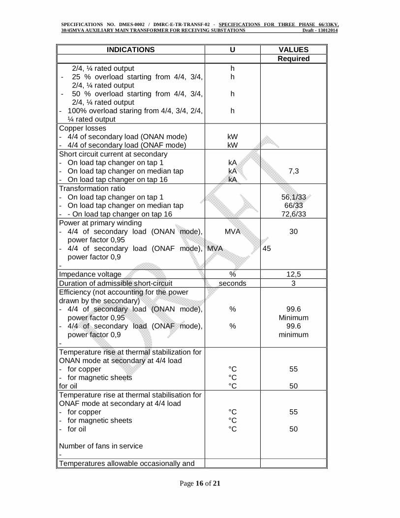
INDICATIONS U VALUES Required
2/4, ¼ rated output - 25 % overload starting from 4/4, 3/4,
2/4, ¼ rated output - 50 % overload starting from 4/4, 3/4,
2/4, ¼ rated output - 100% overload staring from 4/4, 3/4, 2/4,
¼ rated output
h h h h
Copper losses - 4/4 of secondary load (ONAN mode) - 4/4 of secondary load (ONAF mode)
kW kW
Short circuit current at secondary - On load tap changer on tap 1 - On load tap changer on median tap - On load tap changer on tap 16
kA kA kA
7,3
Transformation ratio - On load tap changer on tap 1 - On load tap changer on median tap - - On load tap changer on tap 16
56,1/33 66/33
72,6/33 Power at primary winding - 4/4 of secondary load (ONAN mode),
power factor 0,95 - 4/4 of secondary load (ONAF mode),
power factor 0,9 -
MVA
MVA
30
45
Impedance voltage % 12,5 Duration of admissible short-circuit seconds 3 Efficiency (not accounting for the power drawn by the secondary) - 4/4 of secondary load (ONAN mode),
power factor 0,95 - 4/4 of secondary load (ONAF mode),
power factor 0,9 -
%
%
99.6 Minimum
99.6 minimum
Temperature rise at thermal stabilization for ONAN mode at secondary at 4/4 load - for copper - for magnetic sheets for oil
°C °C °C
55
50 Temperature rise at thermal stabilisation for ONAF mode at secondary at 4/4 load - for copper - for magnetic sheets - for oil Number of fans in service -
°C °C °C
55
50
Temperatures allowable occasionally and
SPECIFICATIONS NO. DMES-0002 / DMRC-E-TR-TRANSF-02 - SPECIFICATIONS FOR THREE PHASE 66/33KV, 30/45MVA AUXILIARY MAIN TRANSFORMER FOR RECEIVING SUBSTATIONS Draft - 13012014
Page 17 of 21
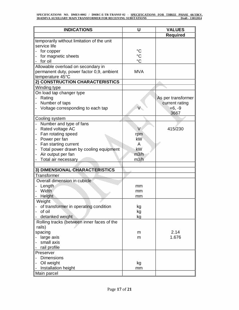
INDICATIONS U VALUES Required temporarily without limitation of the unit service life - for copper - for magnetic sheets - for oil
°C °C °C
Allowable overload on secondary in permanent duty, power factor 0,9, ambient temperature 45°C
MVA
2) CONSTRUCTION CHARACTERISTICS Winding type On load tap changer type - Rating - Number of taps - Voltage corresponding to each tap
V
As per transformer
current rating +6, -9 3667
Cooling system - Number and type of fans - Rated voltage AC - Fan rotating speed - Power per fan - Fan starting current - Total power drawn by cooling equipment - Air output per fan - Total air necessary
V
rpm kW A
kW m3/h m3/h
415/230
3) DIMENSIONAL CHARACTERISTICS Transformer Overall dimension in cubicle
- Length - Width - Height
mm mm mm
Weight - of transformer in operating condition - of oil - detanked weight
kg kg kg
Rolling tracks (between inner faces of the rails) spacing - large axis - small axis - rail profile
m m
2.14 1.676
Preserver - Dimensions - Oil weight - Installation height
kg mm
Main parcel

SPECIFICATIONS NO. DMES-0002 / DMRC-E-TR-TRANSF-02 - SPECIFICATIONS FOR THREE PHASE 66/33KV, 30/45MVA AUXILIARY MAIN TRANSFORMER FOR RECEIVING SUBSTATIONS Draft - 13012014
Page 18 of 21
INDICATIONS U VALUES Required Dimensions : - Length/Width/Height - weight
- with oil - with insert gas
mm
kg kg
Handling, i.e. under hooks height required for travelling crane to enable handling - Complete transformer - - main parcel placed on the trailer
mm mm
Overall dimension drawing number 4) NOISE LEVEL Transformer alone (per testing mode stipulated in IEC standards)
dBA
Overall noise level - at rated voltage and no load - at 110% of rated voltage and no load - at maximum over-induction
dBA dBA dBA dBA
70
5) MISCELLANEOUS INFORMATION - Thermal time constant - of oil - of transformer
h h
- Maximum value of energising current at no load
A peak
- Value of direct and reverse impedance - as seen from primary terminals - as seen from secondary terminals
- Value of zero sequence impedance - as seen from primary terminals - as seen from secondary terminals
Degree of Ingress protection for auxiliary circuit
IP55
(* Approximate only)
SPECIFICATIONS NO. DMES-0002 / DMRC-E-TR-TRANSF-02 - SPECIFICATIONS FOR THREE PHASE 66/33KV, 30/45MVA AUXILIARY MAIN TRANSFORMER FOR RECEIVING SUBSTATIONS Draft - 13012014
Page 19 of 21
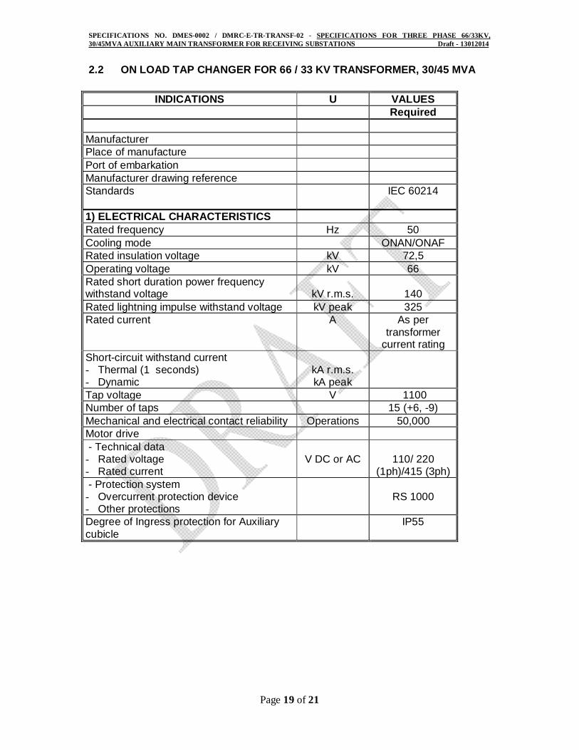
2.2 ON LOAD TAP CHANGER FOR 66 / 33 KV TRANSFORMER, 30/45 MVA
INDICATIONS U VALUES Required Manufacturer Place of manufacture Port of embarkation Manufacturer drawing reference Standards
IEC 60214
1) ELECTRICAL CHARACTERISTICS Rated frequency Hz 50 Cooling mode ONAN/ONAF Rated insulation voltage kV 72,5 Operating voltage kV 66 Rated short duration power frequency withstand voltage
kV r.m.s.
140
Rated lightning impulse withstand voltage kV peak 325 Rated current A As per
transformer current rating
Short-circuit withstand current - Thermal (1 seconds) - Dynamic
kA r.m.s. kA peak
Tap voltage V 1100 Number of taps 15 (+6, -9) Mechanical and electrical contact reliability Operations 50,000 Motor drive - Technical data - Rated voltage - Rated current
V DC or AC
110/ 220
(1ph)/415 (3ph) - Protection system - Overcurrent protection device - Other protections
RS 1000
Degree of Ingress protection for Auxiliary cubicle
IP55

SPECIFICATIONS NO. DMES-0002 / DMRC-E-TR-TRANSF-02 - SPECIFICATIONS FOR THREE PHASE 66/33KV, 30/45MVA AUXILIARY MAIN TRANSFORMER FOR RECEIVING SUBSTATIONS Draft - 13012014
Page 20 of 21
3. TEST SHEET
3.1 AUXILIARY MAIN TRANSFORMERS
INDICATIONS TYPE of TEST
Type Routine On site After Shipment
Measurement of zero sequence impedance X
Temperature rise X Lightning impulse withstand voltage test X
Measurement of noise level X Short circuit withstand test X Tank, Expansion vessel & Radiator Water tight X
Piping welds & joints Water tight X Measurement of windings resistance X Measurement of voltage ratio and check of phase displacement X
Measurement of short circuit impedance and load loss X
Measurement of no-load loss & current X Power frequency withstand voltage test X Short and long duration Induced AC withstand voltage test, with partial discharge measurement
X
On load tap changer functioning X X On load tap changer Aux. Circuits insulation X
Painting & external visual inspection X * X X Core Insulation resistance X * X X Insulation oil breakdown strength X Aux. Circuits insulation X Aux. Circuits operation X Instrumentation & relays calibration X Dissolved Gas Analysis (DGA) X Frequency Response Analysis (FRA) X X
* Tests to be performed just prior shipment.

SPECIFICATIONS NO. DMES-0002 / DMRC-E-TR-TRANSF-02 - SPECIFICATIONS FOR THREE PHASE 66/33KV, 30/45MVA AUXILIARY MAIN TRANSFORMER FOR RECEIVING SUBSTATIONS Draft - 13012014
Page 21 of 21
3.2 ON LOAD TAP CHANGER
INDICATIONS TYPE of TEST
Type Routine On site After Shipment
Mechanical operation X
Oil tank tightness X Selector operation X
These tests shall be performed before the assembly of the tap changer with the transformer.