Red Hat Enterprise Linux-5-Configuration Example - Oracle HA on Cluster Suite-En-US

May 2006
DESIGN MANUAL FOR ROADS AND BRIDGES
VOLUME 4 GEOTECHNICS ANDDRAINAGE
SECTION 2 DRAINAGE
PART 9
HA 119/06
GRASSED SURFACE WATERCHANNELS FOR HIGHWAY RUNOFF
SUMMARY
This Advice Note gives guidance on the hydraulic andstructural design of grassed surface water channel forhighway drainage. The type of system consideredconsists of a shallow surface water channel that is linedwith grass.
INSTRUCTIONS FOR USE
This is a new document to be incorporated into theManual.
1. Remove Contents pages for Volume 4.
2. Insert new Contents pages for Volume 4 datedMay 2006.
3. Insert HA 119/06 into Volume 4, Section 2,Part 9.
4. Please archive this sheet as appropriate.
Note: A quarterly index with a full set of VolumeContents Pages is available separately from TheStationery Office Ltd.

HA 119/06
Grassed Surface WaterChannels for Highway Runoff
Summary: This Advice Note gives guidance on the hydraulic and structural design ofgrassed surface water channel for highway drainage. The type of systemconsidered consists of a shallow surface water channel that is lined with grass.
DESIGN MANUAL FOR ROADS AND BRIDGES
THE HIGHWAYS AGENCY
TRANSPORT SCOTLAND
WELSH ASSEMBLY GOVERNMENTLLYWODRAETH CYNULLIAD CYMRU
THE DEPARTMENT FOR REGIONAL DEVELOPMENTNORTHERN IRELAND

Volume 4 Section 2Part 9 HA 119/06
May 2006
REGISTRATION OF AMENDMENTS
Amend Page No Signature & Date of Amend Page No Signature & Date ofNo incorporation of No incorporation of
amendments amendments
Registration of Amendments

Volume 4 Section 2Part 9 HA 119/06
May 2006
REGISTRATION OF AMENDMENTS
Amend Page No Signature & Date of Amend Page No Signature & Date ofNo incorporation of No incorporation of
amendments amendments
Registration of Amendments

VOLUME 4 GEOTECHNICS ANDDRAINAGE
SECTION 2 DRAINAGE
PART 9
HA 119/06
GRASSED SURFACE WATERCHANNELS FOR HIGHWAY RUNOFF
Contents
Chapter
1. Introduction
2. Safety Aspects
3. Description
4. Environmental Benefits
5. Hydraulic Design Principles
6. Design Capacity of Channel
7. Outlets and Terminal Outfalls
8. Sub-surface Drainage
9. Soil Properties
10. Grass Type Selection
11. Construction Aspects
12. Maintenance
13. Worked Example
14. References and Bibliography
15. Enquiries
Appendix A List of Symbols
Appendix B Tables
Appendix C Figures
Appendix D Plates
DESIGN MANUAL FOR ROADS AND BRIDGES
May 2006

Volume 4 Section 2Part 9 HA 119/06
Chapter 1Introduction
1. INTRODUCTION
General
1.1 This Advice Note gives guidance on thehydraulic and structural design of grassed surface waterchannels for highway drainage. The type of systemconsidered consists of a shallow surface water channelthat is lined with grass. The grass sward reduces theflow velocity in the channel providing flow attenuationand facilitating deposition of suspended sediments andpolluting heavy metals. Although, when compared withconcrete surface water channels, the grassed channelswill require more maintenance in the form of mowing,they do offer environmental benefits: a potential habitatfor local fauna coupled with a better aesthetic value.The system is particularly suited to in-situ constructiontechniques. However, the hydraulic design proceduresprovided are generally applicable and are not limited toa particular method of construction. Although theadvice should be fully taken into account in the designof new schemes (see 1.6), this Advice Note contains nomandatory requirements.
1.2 The function of the surface channel is to collectand convey rainwater runoff from the road surface. Atsuitable points along the channel, water is dischargedinto a separate carrier pipe to the rear, or possiblybeneath the channel.
1.3 This Advice Note should be read in conjunctionwith the following documents in DMRB 4.2 (Ref 2):
• HD 33: Surface and Sub-Surface DrainageSystems for Highways;
• HA 37: Hydraulic Design of Road-Edge SurfaceWater Channels;
• HA 78: Design of Outfalls for Surface WaterChannels;
• HA 83: Safety Aspects of Road Edge DrainageFeatures. Further details are given in TRL Report422 (Ref 3);
• HA 103: Vegetated Drainage Systems forHighway Runoff.
1.4 The use of surface water channels should takeaccount of advice on safety given in HA 83 (DMRB4.2).
1cigp
S
1trghdssw
I
1sorpaOaO
May 2006
.5 The selection of grassed surface water channelsannot be prescribed. Each situation must be consideredndividually taking into account the local landscape,eology, hydrology, climate and the practicality ofrovision for maintenance.
cope
.6 The principles outlined in this Advice Note applyo all schemes of Overseeing Organisations for trunkoads including motorways. They may also be appliedenerally to other new highway schemes and by otherighway authorities for use during the preparation,esign and construction of their own comparablechemes. Grassed surface water channel drainageystems may be installed during major maintenanceorks or as a retro-fit.
mplementation
.7 This Advice Note should be used forthwith for allchemes currently being prepared provided that, in thepinion of the Overseeing Organisation, this would notesult in significant additional expense or delayrogress. In Northern Ireland, this Advice Note will bepplicable to those roads designated by the Overseeingrganisation. Design Organisations should confirm its
pplication to particular schemes with the Overseeingrganisation (see HD 33 - DMRB 4.2).
1/1
Volume 4 Section 2Part 9 HA 119/06
Chapter 2Safety Aspects
2. SAFETY ASPECTS
General
2.1 When considering the use of a grassed surfacewater channel, safety aspects relating to its locationshould be taken into account in accordance with theguidelines given in HA 83, Safety Aspects of Road-edge Drainage Features (DMRB 4.2). Their use in thecentral reserve may not be appropriate if located at thepavement edge.
2.2 Grassed channels will usually be sited adjacent tothe hardstrip or hardshoulder or at the edge of thecarriageway and in front of the safety barrier, where oneis provided. Layout details are given in the ‘A’ Series ofthe Highway Construction Details (HCD) (MCHW 3)(Ref 1). In these locations the maximum design depth offlow in the channel should be limited to 200 mm.Grassed channels can be triangular or trapezoidal incross-section. Non-symmetrical shapes can beconsidered provided account is taken of the followingrecommendations. In verges and central reserves, theside slopes of the channel should not be steeper than1:5 (vertical : horizontal) for triangular and trapezoidalchannels whether symmetrical or not. In veryexceptional cases, the side slope remote from therunning lane may have a slope of 1:4.5 if permitted bythe Overseeing Organisation.
2.3 Grassed triangular channels of depth greater than200 mm should be used only when safety barriers areprovided between the channel and the carriageway.Systems of this type will normally only be justifiedwhen safety barriers are warranted by otherconsiderations. In addition, such systems should not belocated in the zone behind the safety barrier into whichthe barrier might reasonably be expected to deflect onvehicle impact (because of the risk of the vehicleoverturning due to it being too low relative to the safetybarrier). Shallower types of channel may be located inthis deflection zone, or be crossed by the safety barrier(usually at a narrow angle), provided that the combinedlayout complies with the requirements of other relevantparts of the DMRB (Ref 2, note that Volume 1,Section 0, Part 1 contains a contents list and index).
Further advice on such layouts should be sought fromthe Overseeing Organisation.
2.4 The need to minimise safety risks will inevitablymean that the layout of safety barriers and grassed
chanbasuceThreqSyHe
2.5thiusdrterondirsa
2.6disadge(Rloa
2.7covedacohaanroshsuan
May 2006
annels should be agreed at an early stage in designd not left to compromise at later stages. Where safetyrriers are not immediately deemed necessary,fficient space should be provided in the verge orntral reserve to allow for their possible installation.e combined layout must comply with theuirements of TD 19: Requirement for Road Restraintstems (DMRB 2.2.8) and TD 27: Cross Sections andadroom (DMRB 6.1.2).
The constraints on channel geometry given ins document also apply to the outlet arrangementsed to discharge flow from the channel to the carrierain or watercourse. For outlets and channelminations, slopes exceeding 1:4 should not be used any faces, particularly those orthogonal to theection of traffic, unless such faces are behind a
fety barrier.
Gully gratings used in a combined system tocharge water from the surface water channel to thejacent carrier pipe (or to an outfall) should meet theometrical and structural requirements of BS EN 124ef 4) and BS 7903 (Ref 5) and be of the appropriated class.
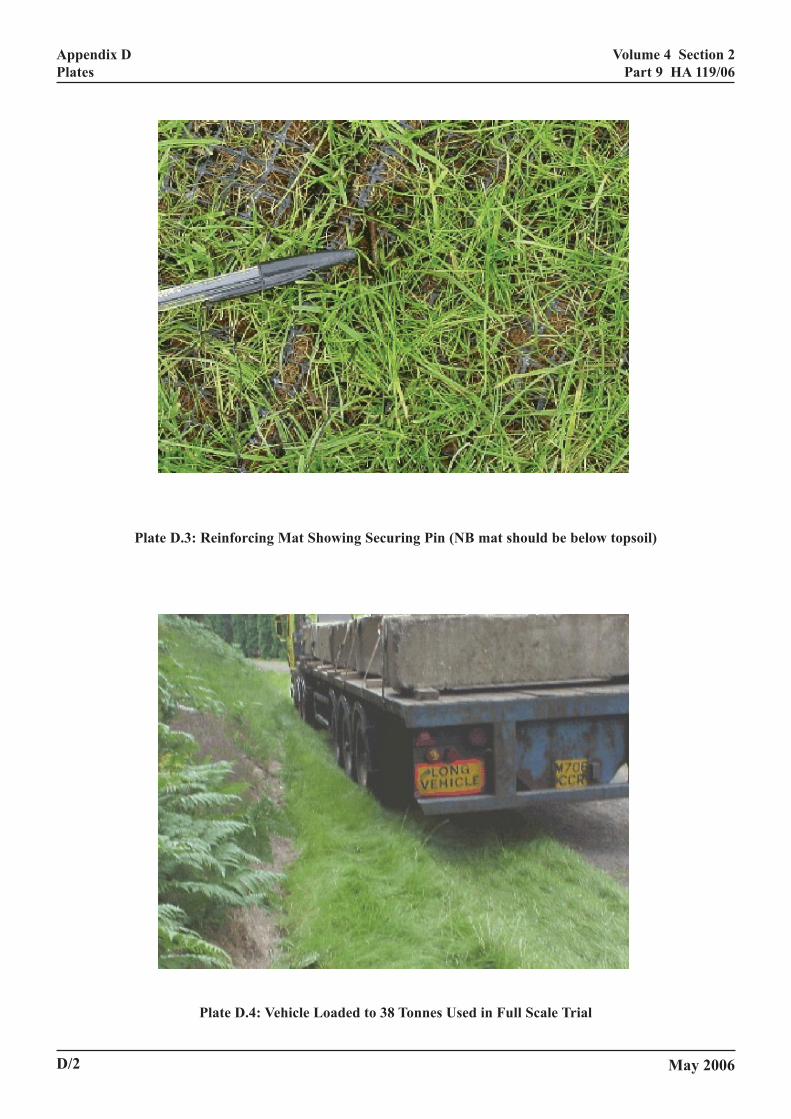
When dry, a grassed channel of appropriatenstruction, should be capable of supporting a heavyhicle, refer to Plate D.4, without incurring significantmage. Where grassed channels are used innjunction with All Purpose Roads, with a one metrerdstrip, and non accidental vehicle loading may beticipated, for example a vehicle standing duringutine maintenance operations, then considerationould be given to locally reinforcing the channelrface at these locations. (Refer to Chapters 11 and 12d Plate D.3.)
2/1

Volume 4 Section 2Part 9 HA 119/06
Chapter 3Description
3. DESCRIPTION
General
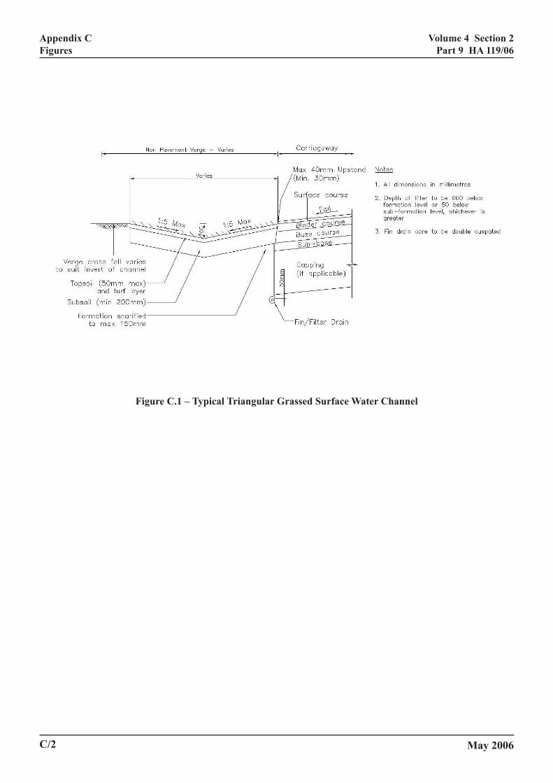
3.1 The drainage system described in this AdviceNote consists of a grassed triangular or trapezoidalsurface water channel that is installed at the pavementedge to collect and convey rainfall runoff from the roadsurface. The cross-sectional geometry of a typicalgrassed surface water channel system is shown inFigure C.1. Recommendations on appropriate methodsof sub-surface drainage are given in Chapter 8.
Ground Water Implications
3.2 The Regulating Authority (RA) should beconsulted whenever grassed surface water channels areproposed because infiltration of runoff through thechannel can potentially impact on the receiving groundwaters. Consultation would be part of theEnvironmental Assessment undertaken in accordancewith the procedures in DMRB 11.3.10 (Ref 2).
3.3 The location of any aquifer should bedetermined, in particular the abstraction source and theprotection afforded. There are three zones:
Source Protection Zone I (SPZ I) – Inner SourceProtection: Immediately adjacent to the abstractionsource and based on 50 day travel (flow) time from anypoint below the water table to the source (50 days is thedecay period for biological contaminants).
Source Protection Zone II (SPZ II) – Outer SourceProtection: This is defined as the 400 day travel time(to provide delay and attenuation of slowly decayingpollutants).
Source Protection Zone III (SPZ III) – SourceCatchment: Is defined as the entire catchment for agroundwater source.
3.4 The use of grassed channels needs to be carefullyconsidered in the vicinity of zones SPZ I and SPZ II, asprotection measures will need to be agreed with the RA.Suitable measures may include the installation of animpermeable membrane beneath the channel. Themembrane should be at a depth sufficient to retainmoisture to maintain grass growth and to minimise therisk of damage should vehicles be driven over thechannel. Note that the use of a cohesive subsoil in the
cp
R
3Dtroocc4
3wshthoInc
3reinaree
May 2006
hannel construction is to be avoided due to poorerformance when driven over.
ecommended Configuration
.5 Grassed channels can be triangular (see Plate.1) or trapezoidal in cross-section; non-symmetricaliangular channels can be considered to take advantagef the verge space (see Figure C.2). The configurationf the grassed channel should be of similaronfiguration to those of the concrete surface waterhannel, see HD 33 (DMRB 4.2) and HA 37 (DMRB.2) for guidance.
.6 The width of the channel may be limited by theidth of available verge. For safety reasons the depthould not exceed 200 mm or side slopes be steeperan 1:5 (vertical : horizontal) for triangular channels,
r 1:4.5 (vertical : horizontal) for trapezoidal channels. order to ensure effective conveyance, grassed
hannel depth should not be less than 150 mm.
.7 Positioning grassed channels in the centralserve, especially at the pavement edge, may beappropriate from both safety and routine maintenance
spects. Their use on high embankments is notcommended as percolation may destabilise the
mbankment slope.
3/1
Volume 4 Section 2Part 9 HA 119/06
Chapter 4Environmental Benefits
FITS
4. ENVIRONMENTAL BENEGeneral
4.1 Grassed surface water channels are a vegetateddrainage system (see HA 103) (DMRB 4.2) and mayalso be considered to be a Sustainable Drainage System(SuDS), in that they use minimal non-replenishablematerials such as quarried stone or oil based products.The system also offers potential environmental benefitsnot found in most conventional highway drainagetechniques.
4.2 The visual environment is improved by theapparent reduction in width of the road, which for arural Dual All Purpose carriageway could be between10 and 15%. Replacing the concrete surface waterchannel by a grassed channel represents a visual‘greening’ of the road.
Flow Attenuation
4.3 The increased surface roughness of the grassedchannel in comparison with that of concrete will reducethe corresponding flow velocity. Comparison betweenaverage flow velocities in the two types of channelindicates velocities in grassed channels around 25% ofthose in concrete channels. A reduction in velocity willincrease the time of flow within the channel andthereby increase the time of concentration.Consequently, the peak discharge flow rate to areceiving watercourse will be less from the grassedchannel.
Sediment Deposition
4.4 The lower flow velocity generates less energythereby reducing the sediment transport ability of thechannel flow. Sediment will settle in the channel bedand be trapped by the grass blades.
Pollution Containment
4.5 Sediment is the prime constituent in the transportof heavy metals and polluting materials, such as lead,copper, zinc, cadmium etc. Metals are mainly containedin the suspended solids carried along by the channelflow and are removed when the solids are deposited assediment. Increased sediment deposition will result inless of these pollutants reaching the receivingwatercourse.
May 2006
4.6 While grasses may not be as effective as reedbeds in absorbing heavy metals and pollutants, the grassroot system may remove some of the sediment bornecontaminants. Table 7.1: Indicative Pollution RiskReduction Factors for Drainage Systems of HA 216:Environmental Assessment Techniques: Road Drainageand the Water Environment (DMRB 11.3.10), ascribesthe same risk reduction factor, 0.4, to grassed channelsas to filter drains, soakaways/infiltration basins andsediment traps.
4.7 Under no, or low, flow conditions, accidentalspillages may be readily contained due to the very lowvelocity of the spillage and the ability of the grass toretain the contaminant by permitting it to soak into thetopsoil. The grass and contaminated soil may beremoved and the channel section reconstructed.
4/1

Volume 4 Section 2Part 9 HA 119/06
INCIPLES
Chapter 5Hydraulic Design Principles
5. HYDRAULIC DESIGN PR
General
5.1 The methods given in Chapter 6 for determiningthe drainage capacities of a grassed channel are basedon the same principles as those used in HA 37 (DMRB4.2) for conventional surface water channels. An outlinedescription of the principles is given in this AdviceNote.
5.2 It is a feature of the grassed channel that thelongitudinal gradients of the channel normally be thesame as the longitudinal gradient of the pavement beingdrained.
5.3 For a section of road at constant longitudinalgradient, the design should involve the following steps:
(1) Assume a suitable size and cross-sectionalgeometry for the surface channel and use themethod given in Chapter 6 to find the length ofroad, L (in m), that can be drained by the channelbefore it reaches its design capacity. This length,L , determines the maximum allowable distancebetween the upstream end of the system and thefirst outlet and also the spacings betweensubsequent outlets to a carrier pipe line.
(2) The carrier pipe should be designed to theprinciples set out in HD 33 (DMRB 4.2).
5.4 The hydraulic capacity of a grassed channel is afunction of the following factors:
• The longitudinal gradient of the road, S (verticalfall per unit distance along the road, in m per m).
• The effective width, WE (in m), of the catchmentdrained by the channel, taking account ifappropriate of any run-off from cuttings (seeChapter 12 and Annex C of HA 37) (DMRB 4.2).
• The size, shape and cross-sectional area of thesurface channel.
• The hydraulic roughness values of the channel,which are dependent on grass type and height, aswell as on flow conditions.
•
•
5itvawagcoa
5dw
wsrr
w
5cl(
w
May 2006
The statistical rainfall characteristics at the site,i.e. the relationship between the rainfall intensity,the duration of the design storm and its frequencyof occurrence.
The variation of rainfall intensity with timeduring the design storm.
.5 The effects of these various factors can be takennto account using a method based on kinematic waveheory. This method provides information about theariation of flow conditions with time during a stormnd enables the duration of storm that produces theorst flow conditions to be determined. The
pplicability of this method to the specific case ofrassed channels where, in contrast with concretehannels, the hydraulic resistance of the grass dependsn the flow conditions in the channel, was investigatednd is described in Escarameia and Todd (Ref 6).
.6 The flow capacity of the channel can beetermined from the Manning resistance equationhich has the form:
nSRAQ
2/13/2= (1)
here Q is the flow rate (in m3/s), A is the cross-ectional area of flow (in m2), and n is the Manningoughness coefficient of the channel. The hydraulicadius, R (in m), of the flow is given by:
PAR = (2)
here P is the wetted perimeter of the channel (in m).
.7 The Manning’s roughness coefficient, n, can bealculated using the following formulae derived fromaboratory tests and validated using field trial dataRef 6):
VRHn )1(0048.005.0 α++= (3)
ith α = 0 for Perennial Ryegrass dominated grassmixturesα = 1 for Fescues dominated grass mixtures
5/1
Volume 4 Section 2Part 9 HA 119/06
Chapter 5Hydraulic Design Principles
where H is the grass height in metres, V is the velocityin metres/second and R is the hydraulic radius inmetres.
Equation (3) is applicable for VR>0.002. The greatmajority of design cases will be in that category;however, if any situations arise where VR<0.002, n canbe calculated using the following expression:
n = 0.05 + 2.4(1 + α)H (4)
5.8 Rainfall statistics for short-duration storms in theUK can be approximated by the following equation:
( ) ( ) ( )5min24.04.07.32565.0
223.0 MT
TNIO−
−= (5)
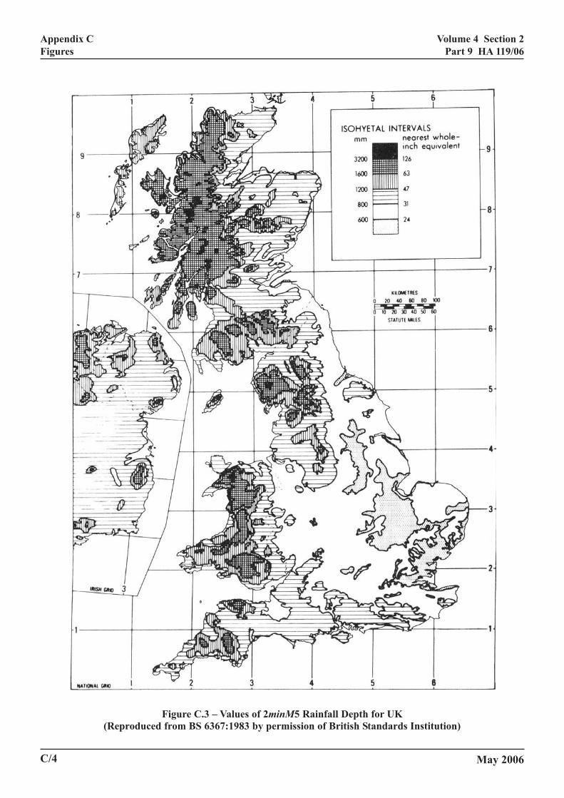
where IO is the mean rainfall intensity (mm/h) occurringin a storm of duration T (minutes) with a return periodof N (years), such that a storm of this intensity willoccur on average once every N years. The quantity2minM5 is the depth of rainfall (in mm) occurring in astorm at the specified geographical location during aperiod of T = 2 minutes with a return period of N = 5years. The variation of 2minM5 with location in the UKis shown in Figure C.3. Details of the basis for Equation(5) are given in Annex A of HA 37 (DMRB 4.2).
5.9 The rainfall intensity in a storm is not usuallyconstant but varies with time. The design equationsgiven in Chapter 6 for the drainage capacities ofchannels assume that the intensity varies in accordancewith what is termed the 50% summer profile, as definedin Volume 2 of the Flood Estimation Handbook (Ref 7).With this profile, the peak intensity at the mid-point ofthe storm is approximately 3.9 times the mean intensity,IO , averaged over the total duration of the storm.
5.10 The higher resistance of grass, when comparedwith concrete and other artificial materials, generateslower flow velocities and flow rates in the channel (seeAppendix B). For channels of equivalent size and slope,mean flow velocities in grassed channels can be of theorder of 25% of those in concrete channels. Attenuationof peak flows is therefore better achieved in grassedchannels and consequently the rate of discharge ofrunoff into the receiving watercourse is significantlyslowed down.
May 20065/2
Volume 4 Section 2Part 9 HA 119/06
CHANNEL
Chapter 6Drainage Capacity of Channel
6/1
May 20066. DRAINAGE CAPACITY OF
Determination of Hydraulic Resistance
6.1 The first step in determining the capacity ofgrassed channels is concerned with the determination ofthe grass resistance coefficient. The procedure forobtaining this value is as follows:
• Define the cross-sectional characteristics of thechannel. Assume design water depth is equal to0.200m.
• Determine the hydraulic radius, R, of the channelas the ratio of the cross-sectional area and thewetted perimeter for the design water depth, seeEquation (2). For the determination of thesequantities, consider that the boundaries of thegrassed channel are defined by the level of thesoil from which the grass grows (as opposed tothe tips of the grass blades).
• Decide on the grass mixture type (Fescuesdominated mixture or Perennial Ryegrassdominated mixture) (see Chapter 10).
• For design purposes assume a grass height ofH=0.05m for Fescues dominated mixture andH=0.075m for Perennial Ryegrass dominatedmixture.
• Using the value of the longitudinal slope of theroad, S, calculate the term H/(R5/3S1/2), where H isthe grass height (in metres) and R is the hydraulicradius (in metres) and calculate the followingexpression:
2/13/51
05.0
SRmHn
−=
(6)
where m = 0.0048 for Perennial Rye Grass and m= 0.0096 for Fescues dominated mix.
Values of n are typically within the range 0.05 to0.1.
• Follow the procedure described in HA 37(DMRB 4.2) to find the drainage length (seebelow).
6.2 Factors that influence the effective value of n arethe grass stem density, grass stem length, soil
comtheor d
Dra
6.3dratermmawiltheoutAltspadrasys
6.4dralendesallodowto bpipothCha
6.5andrainof rhydfolldrasym
L =
wh
•
•
position, energy losses caused by the flow entering channel from the road, and the presence of sedimentebris deposited in the channel.
inage Length
The surface channel is divided into separateinage lengths by the intermediate outlets and
inal outfall. For a given size of channel, theximum allowable distance between adjacent outletsl vary with the longitudinal gradient of the road and effective width of the catchment being drained. Thelets may not, therefore, be equally spaced.ernatively, it is possible to use a standardisedcing equal to the length of road that the channel canin in the most critical section of the carrier pipetem.
For an individual section of surface channel, theinage length, L (in m), is defined as the maximumgth of road that can be drained by the channel underign conditions without the flow exceeding thewable water depth in the channel. At thenstream end of the drainage length, the flow needse discharged from the channel to either the carrier
e via an intermediate outlet, or to a watercourse orer drainage system via a terminal outfall (seepter 7).
In addition to the physical properties of the road the channel, the value of L depends upon thefall characteristics at the site and the selected valueeturn period for the design storm. Based on theraulic principles described in Chapter 5, theowing equation can be used to determine values ofinage length for triangular surface channels ofmetrical cross-section:
( )( )
( )( )[ ] 62.1
362.02/1
3/122
29.26
5min24.0
41056.1
MWN
nS
YB
YB
E
−−
+× (7)
ere:
Y is the design depth of flow in the triangularchannel (in m) – see 2.2 and Figure C.1 or C.2;
B is the corresponding surface width of flow (inm);
Volume 4 Section 2Part 9 HA 119/06
Chapter 6Drainage Capacity of Channel
• S is the longitudinal gradient of the channel (in mper m);
• n is the Manning roughness coefficient of thechannel (obtained from Equation (6));
• WE is the effective width of the catchmentdrained by the channel (in m);
• N is the return period of the design storm (inyears);
• 2minM5 is a value of rainfall depth (in mm)characteristic of the geographical location of thesite – see 5.8 and Figure C.3.
6.6 Equivalent formulae for the drainage capacitiesof other cross-sectional shapes of channel (asymmetrictriangular, trapezoidal, rectangular and dished) aregiven in Chapter 5 of HA 37 (DMRB 4.2).
Maximum Flow Capacity
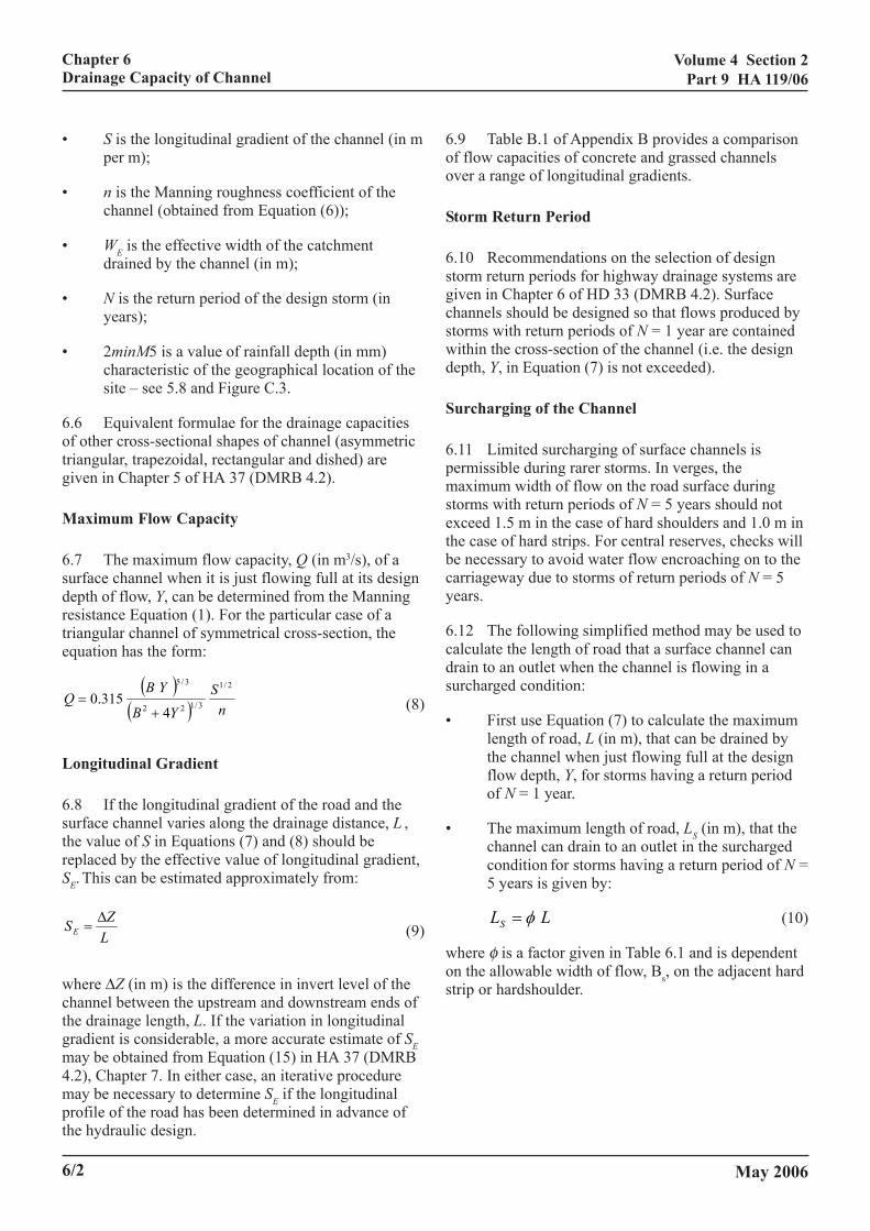
6.7 The maximum flow capacity, Q (in m3/s), of asurface channel when it is just flowing full at its designdepth of flow, Y, can be determined from the Manningresistance Equation (1). For the particular case of atriangular channel of symmetrical cross-section, theequation has the form:
( )( ) n
SYB
YBQ
2/1
3/122
3/5
4315.0
+= (8)
Longitudinal Gradient
6.8 If the longitudinal gradient of the road and thesurface channel varies along the drainage distance, L ,the value of S in Equations (7) and (8) should bereplaced by the effective value of longitudinal gradient,SE. This can be estimated approximately from:
LZSE
∆= (9)
where ∆Z (in m) is the difference in invert level of thechannel between the upstream and downstream ends ofthe drainage length, L. If the variation in longitudinalgradient is considerable, a more accurate estimate of SEmay be obtained from Equation (15) in HA 37 (DMRB4.2), Chapter 7. In either case, an iterative proceduremay be necessary to determine SE if the longitudinalprofile of the road has been determined in advance ofthe hydraulic design.
6/2
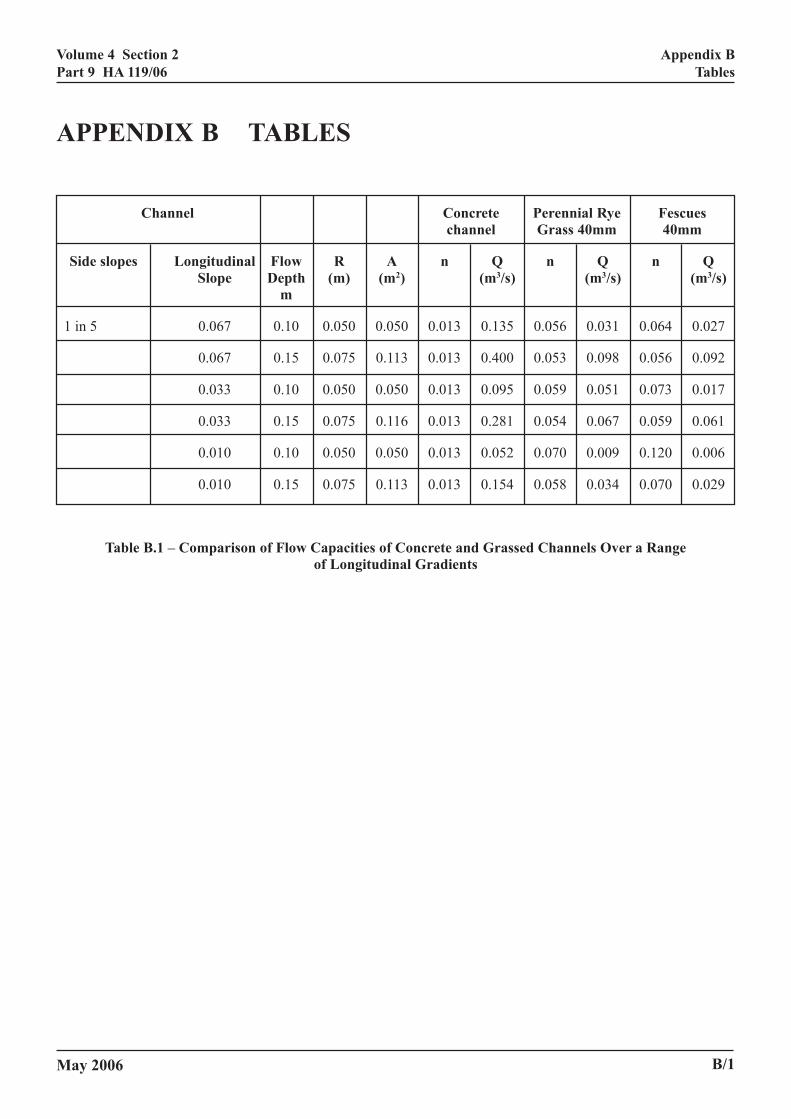
6.9 Table B.1 of Appendix B provides a comparisonof flow capacities of concrete and grassed channelsover a range of longitudinal gradients.
Storm Return Period
6.10 Recommendations on the selection of designstorm return periods for highway drainage systems aregiven in Chapter 6 of HD 33 (DMRB 4.2). Surfacechannels should be designed so that flows produced bystorms with return periods of N = 1 year are containedwithin the cross-section of the channel (i.e. the designdepth, Y, in Equation (7) is not exceeded).
Surcharging of the Channel
6.11 Limited surcharging of surface channels ispermissible during rarer storms. In verges, themaximum width of flow on the road surface duringstorms with return periods of N = 5 years should notexceed 1.5 m in the case of hard shoulders and 1.0 m inthe case of hard strips. For central reserves, checks willbe necessary to avoid water flow encroaching on to thecarriageway due to storms of return periods of N = 5years.
6.12 The following simplified method may be used tocalculate the length of road that a surface channel candrain to an outlet when the channel is flowing in asurcharged condition:
• First use Equation (7) to calculate the maximumlength of road, L (in m), that can be drained bythe channel when just flowing full at the designflow depth, Y, for storms having a return periodof N = 1 year.
• The maximum length of road, LS (in m), that thechannel can drain to an outlet in the surchargedcondition for storms having a return period of N =5 years is given by:
LLS φ= (10)
where φ is a factor given in Table 6.1 and is dependenton the allowable width of flow, Bs, on the adjacent hardstrip or hardshoulder.
May 2006

Volume 4 Section 2Part 9 HA 119/06
Chapter 6Drainage Capacity of Channel
Road Values of φφφφφcross-fall
Allowable width Allowable widthon hard strip on hardshoulder
Bs = 1m Bs = 1.5m
1:30 1.5 1.8
1:40 1.4 1.6
1:50 1.2 1.4
Table 6.1 – Values of φφφφφ
This simplified method assumes that the channel has asymmetrical triangular profile and provides estimates ofLS that will tend to err on the conservative side.
6.13 The maximum flow capacity of the channel, QS(in m3/s), under surcharged conditions can be estimatedfrom:
QQS φ575.1= (11)
where the value of Q is the design capacity of thechannel obtained from Equation (8).
Flow By-passing at Intermediate Outlets
6.14 Because velocities in grassed channels are so lowin comparison with concrete, it is expected that, evenunder surcharged conditions, the volume of flow by-passing the gratings would be minimal, therefore outletgratings are designed on 100% efficiency.
May 2006 6/3

Volume 4 Section 2Part 9 HA 119/06
AL OUTFALLS
.
Chapter 7Outlets and Terminal Outfalls
7. OUTLETS AND TERMIN
General
7.1 The outlet from the channel should be of similararrangement to that of concrete channels, described inHA 78 (DMRB 4.2). The grating may be either flat orV-shaped to correspond with the channel profile. Toavoid dangers to vehicles or flooding, care should betaken to ensure the level of the grating is not higherthan the invert level at the centre of the channel.
7.2 The growth of grass around the outlet mayobstruct flow into the grating. To minimise the risk ofthis occurring, the immediate area around the gratingshould be paved to form an apron. (See also 7.5 below.)The surround (apron) to the grating acts as a transitionfrom the grassed channel; and may be formed usingconcrete or plastic cellular block grass reinforcement,hence incorrect positioning of the apron will beexpensive to rectify.
7.3 The terminal outlet may contain more than onegrating, which may necessitate extending the apronbeyond the downstream end of the channel. Refer toFigure C.5B and to the terminal outlet detail in HA 78(DMRB 4.2).
7.4 The piped sub-surface drainage system, e.g. Type6 fin drain, may be connected to intermediate chambersbut should be connected to the terminal outlet chamber.Ensure that the level of the outlet from the chamber isbelow this sub-surface pipe so that surcharge will notresult in a back flow of water into the sub-surface drain.
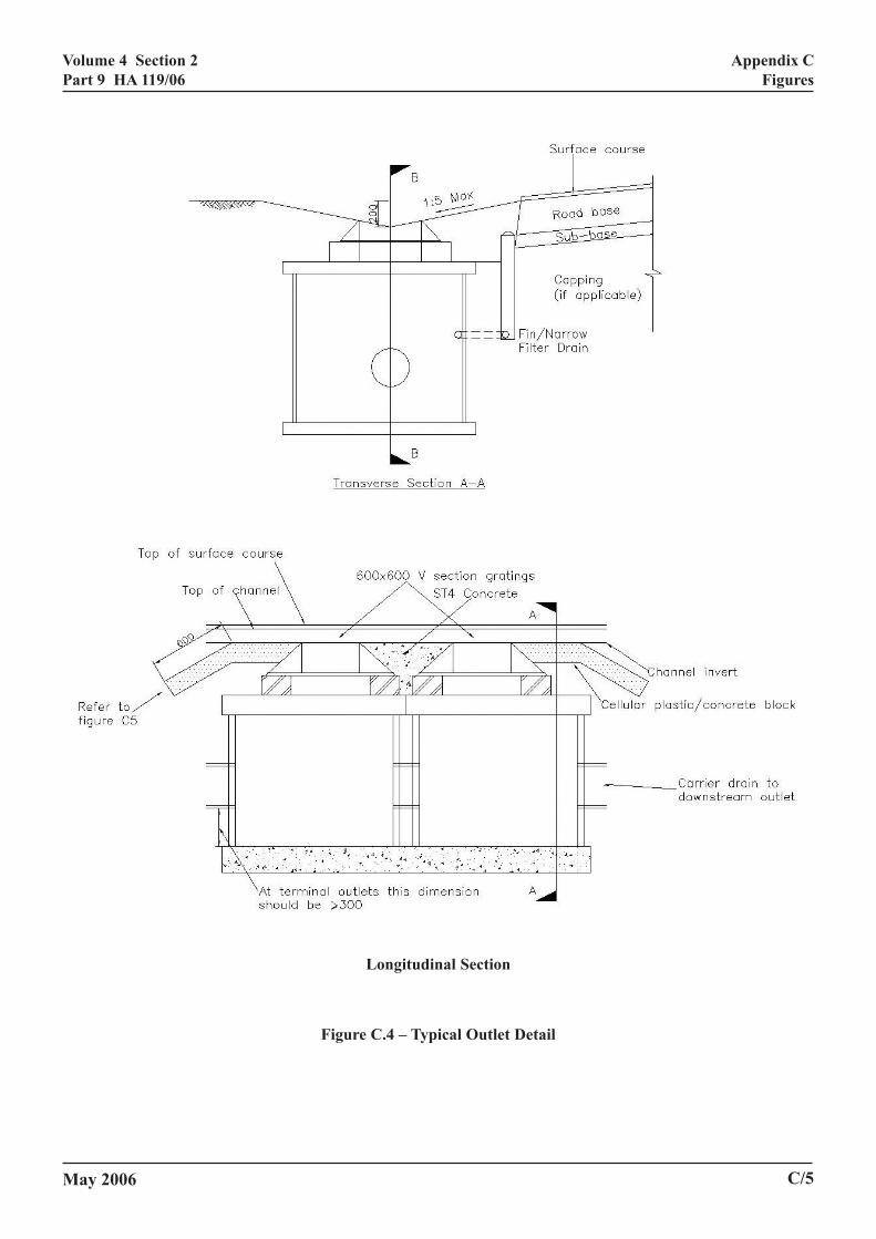
7.5 The outlets from the channel form a solidobstruction within an area of comparatively softchannel construction. Any vehicle wheel that impactswith the outlet structure could be damaged or, iftravelling at a high velocity, the vehicle itself may bedamaged. To minimise this risk it is recommended thata transition zone in the form of an apron, is constructedaround the outlet structure. This apron should be of acellular structure, comprising concrete or plastic blocksincorporating holes for topsoil and grass growth,inclined to slope downwards from the edge of the outletto below the channel, see detail in Figure C.4. Thisshould absorb much of the energy and protect both thevehicle and the structure.
May 2006
Intermediate Outlets
7.6 Intermediate outlets for grassed channels, seeFigures C.4 and C.5A, consist of gratings, installed inthe base of the channel, that discharge the flow from thesurface water channel to a carrier pipeline or, in certaincircumstances, directly to a watercourse.
7.7 The hydraulic design of the gratings (type,spacing, number) is described in HA 78 (DMRB 4.2).The following alternative geometries for intermediateoutlets, presented in HA 78 (DMRB 4.2), are generallysuitable for grassed channels:
(1) In-line outlet, the preferred option, where thewater is essentially collected symmetricallythrough the channel invert (see Figures B5, B7and B9 of HA 78, DMRB 4.2); or
(2) Off-line outlet, where the channel is widenedaway from the carriageway and the outlet isoffset from the centreline of the channel (seeFigures B6, B8 and B10 of HA 78, DMRB 4.2).
For triangular channels the in-line design is generallymore efficient than the off-line design, but reasons forchoosing between them will mainly depend onconstructional aspects (see Chapter 11). Other factorsbeing equal, in-line outlets are preferable to off-lineoutlets because they can enable use of a narrower verge
Terminal Outfalls
7.8 Terminal outfalls comprise chambers withcatchpits that also receive flow from the grassedchannel and convey the flow to a suitable watercourse,ditch or continuation carrier pipe.
7.9 To avoid a vehicle losing control when a channelis not protected by a safety barrier, the upper surface ofthe terminal outfall should terminate with a smoothtransition, without abrupt changes in level or width(following the recommendations in 3.16 of HA 78,DMRB 4.2).
7.10 The plan shape of the chamber will bedetermined by the layout of the gratings forming theterminal outfall. The invert level of the outgoing pipefrom the chamber should be governed by the followingtwo criterias:
7/1

Volume 4 Section 2Part 9 HA 119/06
Chapter 7Outlets and Terminal Outfalls
(1) The invert level should be set at a minimum of300 mm above the bottom of the chamber toprovide an adequate volume for sedimentretention.
(2) The invert level should be such that the waterlevel in the chamber does not rise high enough toprevent flow discharging freely from the surfacechannel into the chamber.
7.11 In order to meet criterion (2) in 7.10, it isrecommended that the water level in the chambershould be at least 150 mm below the underside of thegratings when the chamber is receiving flow from thechannel under surcharged conditions. The height Z (inm) of the water surface in the chamber above the invertof the outgoing pipe can be estimated from theequation:
4
2
23.0 2
D
QDZ += (12)
where D is the diameter of the outgoing pipe (in m) andQ is the design flow rate (in m3/s).
7.12 The gradient and diameter of the outgoing pipefrom the chamber should be determined from a suitableresistance equation or flow tables (such as HRWallingford and Barr, (Ref 8)) assuming that the pipe isjust running full at the design flow rate, Q
.
7.13 An example of a suitable layout for a terminaloutfall chamber is given in Figures C.4 and C.5B.
Steep Roads
7.14 On steep roads (typically with gradients ofS > 1/50), the flow collection efficiency of the gratingsmay be insufficient due to the effect of high watervelocities in the surface channel. There is currentlyinsufficient knowledge of grassed channel performanceat steep gradients. It is, therefore, recommended thatalternative drainage systems are used in this situation.
May 20067/2
Volume 4 Section 2Part 9 HA 119/06
May 2006
8. SUB-SURFACE DRAINAGE
General
8.1 The sub-surface water flow occurring due towater percolating through the bed of the channel mustbe prevented from entering the unbound pavementfoundation, where the presence of moisture can causepremature failure of the pavement.
Drainage System
8.2 A sub-surface drainage system should beprovided to ensure that any percolation through thechannel is intercepted before reaching the unboundpavement layers; a typical detail is shown in Figure C.1.
8.3 A suitable system is the installation of a fin drain,Type 5 or 6 in Detail F18 of the HCD, (MCHW 3), atthe edge of the pavement construction. The fin drainshould incorporate a double cuspated central core, madefrom a suitable impermeable material such aspolyethylene or polypropylene, which acts as a barrierbetween the two constructions.
8.4 The top of the fin drain should be located abovethe top of the pavement sub-base level, but care isnecessary to ensure that the fin does not protrude intothe grassed topsoil.
8.5 Where an impermeable liner is installed beneaththe top soil layer, the liner should extend over the sub-surface drainage.
Chapter 8Sub Surface Drainage
8/1

Volume 4 Section 2Part 9 HA 119/06
Chapter 9Soil Properties
9. SOIL PROPERTIES
General
9.1 The channel should comprise of graded subsoil, alayer of topsoil and sub-surface drainage (see Chapter8). The subsoil should be graded to the required cross-sectional and longitudinal profiles.
9.2 The channel may be either seeded or lined withturf. Where seeded directly on to the topsoil, the depthof topsoil should be minimal, around 35mm, to ensurethat the grass roots penetrate the subsoil and bond thetwo layers together.
9.3 A geo-grid may be placed between the two soillayers to provide reinforcement until the grass becomesestablished. The use of a biodegradable material ispreferable and should provide protection for some 2 to3 years. The geo-grid is usually held in place byU-shaped steel pins or staples. The presence of thestaples should be borne in mind when considering theuse of grassed channels, especially where animpermeable liner is required (see 3.4).
Subsoil Requirements
9.4 Advice on suitable soils and their placement isgiven in HA 56, The Good Roads Guide: New RoadsPlanting, Vegetation and Soils (DMRB 10.1.2) (Ref 2).The formation on which the subsoil is spread should beroughened to a depth of 150mm to provide a keybetween the two materials.
9.5 The subsoil should be non cohesive and fairlypermeable, having permeability in the order of 10-4m/s,after compaction, to ensure that the grass roots get airas well as water.
9.6 The subsoil should be free from stones largerthan 50mm and, where a membrane is used, free fromflints.
Topsoil Requirements
9.7 The topsoil used should comply withBS 3882 Specification for topsoil (Ref 11), generalpurpose topsoil, screened for stones larger than 50mm.
May 2006
9.8 To ensure good grass growth it is recommendedthat, in terms of textural classification, the soil shouldbe a sandy loam or loamy sand, with a pH greater than5.5.
9.9 The ideal depth of topsoil is around 35mm butshould not exceed 50mm as greater depths of topsoilwill encourage the growth of weeds and other forms ofvegetation.
Topsoil Preparation
9.10 The steps for seedbed/turfbed preparation are asfollows:
• cultivation of the topsoil and rolling, undersuitable ground conditions to form the seedbed;
• application of lime, dependent on pH test results.Acid soils, for example, the pH range is from 6.0to 6.5;
• application of seedbed fertiliser e.g. 10:15:10(N:P2O5:K2O) at 30 g/m2;
• final raking or harrowing before seeding/hydroseeding or turfing.
9/1

Volume 4 Section 2Part 9 HA 119/06
N
s of Different Establishment Methods
Chapter 10Grass Type Selection
10. GRASS TYPE SELECTIO
Suitable Grass Types
10.1 No standard verge mix is specified in Clause3005 of the SHW (MCHW 1).
10.2 When selecting the most appropriate grass typesfor surface water channels the main issues to beconsidered are:
• suitability of grasses for different climatic areas;
• ease of establishment;
• salt tolerance;
• susceptibility to pollution from exhaustemissions and runoff from road surfaces;
• tolerance of the wetter conditions that mayprevail in drainage channels;
• growth rates;
•
•
R
1piedpb
G
1t(1
Method Advantages
Seeding Control over grass seed used.
Low cost.
Seed will generally remain dormanthere are hot dry spells after sowinwill establish when suitable weathconditions return.
Hydroseeding Control over grass seed used.
Less risk of seed loss if heavy rainoccurs during establishment.
Less risk of erosion.
Turfing Instant grass cover.
Less risk of erosion.
Table 10.1 – Advantages and Disadvantage
May 2006
erosion control;
recovery rates from damage.
egional Variation in Climate
0.3 A wide range of cool season grasses isotentially available within grassed drainage channelsn the UK. The climatic range is probably not greatnough to justify differences in seed mixtures forifferent parts of the country, but grasses thatredominate after establishment will be influenced byoth climate and soil type.
rass Establishment
0.4 The advantages and disadvantages of variousechniques for establishing grass within the channelseeding, hydro-seeding and turfing) are set out in Table0.1.
Disadvantages
Potential loss of seed if heavy rainfalloccurs during establishment.Greater risk oferosion.
t ifg buter
More expensive than conventional seeding.
High initial cost.
High labour requirement/cost for laying.
Cost of mowing.
Vulnerable to drying out if hot, dry spelloccurs after laying.
Unless specifically grown for grasseddrainage channels, may not have the grassspecies required.
10/1
Volume 4 Section 2Part 9 HA 119/06
e.
r
Chapter 10Grass Type Selection
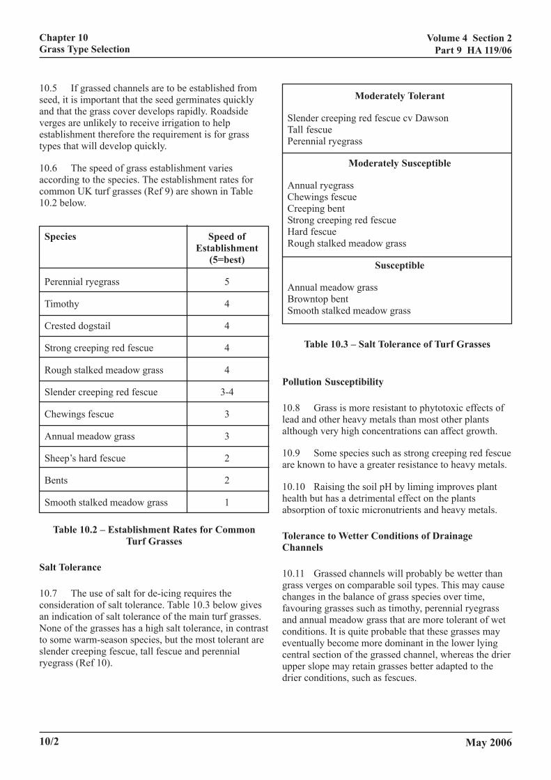
10.5 If grassed channels are to be established fromseed, it is important that the seed germinates quicklyand that the grass cover develops rapidly. Roadsideverges are unlikely to receive irrigation to helpestablishment therefore the requirement is for grasstypes that will develop quickly.
10.6 The speed of grass establishment variesaccording to the species. The establishment rates forcommon UK turf grasses (Ref 9) are shown in Table10.2 below.
Species Speed ofEstablishment
(5=best)
Perennial ryegrass 5
Timothy 4
Crested dogstail 4
Strong creeping red fescue 4
Rough stalked meadow grass 4
Slender creeping red fescue 3-4
Chewings fescue 3
Annual meadow grass 3
Sheep’s hard fescue 2
Bents 2
Smooth stalked meadow grass 1
Table 10.2 – Establishment Rates for CommonTurf Grasses
Salt Tolerance
10.7 The use of salt for de-icing requires theconsideration of salt tolerance. Table 10.3 below givesan indication of salt tolerance of the main turf grasses.None of the grasses has a high salt tolerance, in contrastto some warm-season species, but the most tolerant areslender creeping fescue, tall fescue and perennialryegrass (Ref 10).
10/2
Moderately Tolerant
Slender creeping red fescue cv DawsonTall fescuePerennial ryegrass
Moderately Susceptible
Annual ryegrassChewings fescueCreeping bentStrong creeping red fescueHard fescueRough stalked meadow grass
Susceptible
Annual meadow grassBrowntop bentSmooth stalked meadow grass
Table 10.3 – Salt Tolerance of Turf Grasses
Pollution Susceptibility
10.8 Grass is more resistant to phytotoxic effects oflead and other heavy metals than most other plantsalthough very high concentrations can affect growth.
10.9 Some species such as strong creeping red fescuare known to have a greater resistance to heavy metals
10.10 Raising the soil pH by liming improves planthealth but has a detrimental effect on the plantsabsorption of toxic micronutrients and heavy metals.
Tolerance to Wetter Conditions of DrainageChannels
10.11 Grassed channels will probably be wetter thangrass verges on comparable soil types. This may causechanges in the balance of grass species over time,favouring grasses such as timothy, perennial ryegrassand annual meadow grass that are more tolerant of wetconditions. It is quite probable that these grasses mayeventually become more dominant in the lower lyingcentral section of the grassed channel, whereas the drieupper slope may retain grasses better adapted to thedrier conditions, such as fescues.
May 2006
Volume 4 Section 2Part 9 HA 119/06
Chapter 10Grass Type Selection
Growth Rate
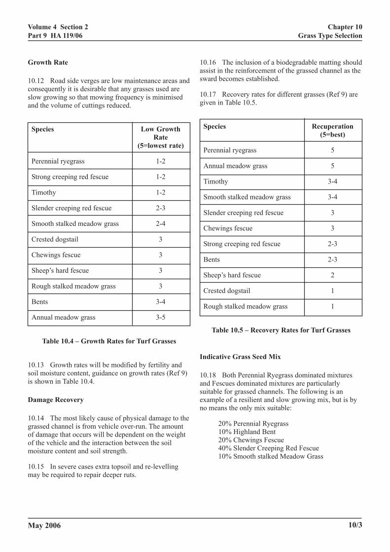
10.12 Road side verges are low maintenance areas andconsequently it is desirable that any grasses used areslow growing so that mowing frequency is minimisedand the volume of cuttings reduced.
Species Low GrowthRate
(5=lowest rate)
Perennial ryegrass 1-2
Strong creeping red fescue 1-2
Timothy 1-2
Slender creeping red fescue 2-3
Smooth stalked meadow grass 2-4
Crested dogstail 3
Chewings fescue 3
Sheep’s hard fescue 3
Rough stalked meadow grass 3
Bents 3-4
Annual meadow grass 3-5
Table 10.4 – Growth Rates for Turf Grasses
10.13 Growth rates will be modified by fertility andsoil moisture content, guidance on growth rates (Ref 9)is shown in Table 10.4.
Damage Recovery
10.14 The most likely cause of physical damage to thegrassed channel is from vehicle over-run. The amountof damage that occurs will be dependent on the weightof the vehicle and the interaction between the soilmoisture content and soil strength.
10.15 In severe cases extra topsoil and re-levellingmay be required to repair deeper ruts.
May 2006
10.16 The inclusion of a biodegradable matting shouldassist in the reinforcement of the grassed channel as thesward becomes established.
10.17 Recovery rates for different grasses (Ref 9) aregiven in Table 10.5.
Species Recuperation(5=best)
Perennial ryegrass 5
Annual meadow grass 5
Timothy 3-4
Smooth stalked meadow grass 3-4
Slender creeping red fescue 3
Chewings fescue 3
Strong creeping red fescue 2-3
Bents 2-3
Sheep’s hard fescue 2
Crested dogstail 1
Rough stalked meadow grass 1
Table 10.5 – Recovery Rates for Turf Grasses
Indicative Grass Seed Mix
10.18 Both Perennial Ryegrass dominated mixturesand Fescues dominated mixtures are particularlysuitable for grassed channels. The following is anexample of a resilient and slow growing mix, but is byno means the only mix suitable:
20% Perennial Ryegrass10% Highland Bent20% Chewings Fescue40% Slender Creeping Red Fescue10% Smooth stalked Meadow Grass
10/3
Volume 4 Section 2Part 9 HA 119/06
CTS
Chapter 11Construction Aspects
11. CONSTRUCTION ASPE
Verge Ancillaries
11.1 A large number of ancillary structures can bepositioned adjacent to the carriageway and will requireaccommodation within, or close to, the grassed channeland to which access will be required. These structurescan include fixed sign and variable message signstructures, gantries, lighting and CCTV columns,motorway communications cabinets and roadsideemergency telephones.
Ducted cables
11.2 Ducts for motorway communications cables arelocated in the verge. The location for the ducts is shownon drawings HCD MCX 0810 (MCHW 3a).
11.3 Ducts run both parallel to and perpendicular tothe carriageway and require the construction ofchambers at changes in direction. It is essential thatchambers are remote from the grassed channel as ductsare a means of introducing surface water into thepavement construction. It is also essential that thegrassed channels do not run off surface water on to thechamber tops allowing the introduction of surface waterinto the duct network. The arrangement of chambersand motorway communications cabinets are shown ondrawings HCD MCX 0812 (MCHW 3a). The depth ofducts is shown on drawings HCD MCX 0814 (MCHW3a).
Directly Buried Cables
11.4 Trenches in the verge for directly buriedmotorway communications cables are shown ondrawing HCD MCX 0140 (MCHW 3a).
Detector Loops
11.5 Detector loops in the carriageway surface andloop joint chambers in the verge result in very shallowcables being present at the carriageway edge. Thedesigner should be aware of the potential conflictbetween these cables and the grassed channel. Detectorloops are generally installed at 500m intervals. HD20(DMRB 9.3) and HCD G9 (MCHW 3) provideinformation.
May 2006
Signage
11.6 Signs are generally remote from the pavementedge and are protected by safety barriers. The designershould ensure that no signs encroach into the channel.Marker posts may encroach into the grassed channeland care should be taken to ensure that their installationwill not result in any impermeable membrane beingpunctured.
Lighting Columns
11.7 Lighting columns should be remote from thepavement edge, however where lighting columns areproposed, the designer should ensure that anywaterproof membrane used is brought around thestructure and that the columns themselves are protectedfrom channel flows.
Safety Barriers
11.8 Barriers may encroach into the grassed channeland any impermeable membrane should be positionedaround the posts, refer also to Chapter 2.
11.9 The presence of barriers may adversely affectthe maintenance (mowing) of the grass and hence thesuitability of grassed channels where long sections ofbarriers are proposed.
Grassed Channel Construction
11.10 It is recommended that a fin drain is installed atthe edge of pavement to intercept infiltration throughthe grassed channel before it reaches the pavementconstruction (see Chapter 8) and similarly interceptflows from beneath the pavement. The recommendedfin drain is either a Type 5 or Type 6 (see F18 and F19of the HCD - MCHW 3) with a double cuspated core.
11.11 During construction of the channels, temporarymeasures may be necessary to prevent surface runofffrom the pavement, or verge, washing away the topsoilor surcharging the fin drain.
11.12 To reduce the risk of topsoil becoming saturateddue to heavy rain, subsoil (where imported) and topsoilplacement should commence at the highest point of thechannel and work downstream.
11/1

Volume 4 Section 2Part 9 HA 119/06
Chapter 11Construction Aspects
11.13 The subsoil should be well compacted, ifpossible in layers approximately 100mm thick and up to50mm of topsoil spread and compacted on top. Anallowance should be made for the thickness of turf, ifused, when defining the final level of the topsoil. Notethat subsoil and topsoil, when placed in landscapedareas are not normally compacted, however, in order tominimise the risk of damage caused by vehicles runninginto the channel, the soils should be compacted in thisinstance.
11.14 Where turf is used, this should be placedimmediately after compaction of the topsoil to minimisethe risk of soil fines being washed away by surfacerunoff. Turfing offers advantages over hydro-seeding inthat it will give a much greater level of initial protectionto the topsoil and hydro-seeding is very dependent onthe quality of the seed mixture and the fibrereinforcement.
11.15 The grassed channel should be operational atthe end of the road construction stage. To avoid longestablishment times in Winter months as well as theinclement weather of the hotter and colder months,grassed channel construction should preferably beundertaken in early Spring or early Autumn.
Use in Combination with a French Drain
11.16 The typical filter (French) drain will be between600mm and 1000mm wide and located against thepavement edge. Where it is proposed to remediate aproblem such as stone scatter, by applying a topsoiledsurfacing, it may be practical to incorporate a grassedchannel in the surfacing. A detail for a grass surface tofilter drains is shown in B15 and in F2 Type L and TypeM of the HCD (MCHW3).
11.17 To be viable, there needs to be an additionalwidth of verge behind the French drain that can beincluded in the construction of the grassed channel.
11.18 As a surfacing to existing filter (French) drains,sufficient stone filter medium and depth of adjacentverge material should be removed to permit theformation of the 200mm channel and sufficient depth oftopsoil. A geotextile may be positioned over the filtermaterial to prevent topsoil (and sub-soil) fromcontaminating the drain, but still permitting water tosoak through.
11/2
11.19 The properties of the geotextile shouldcomprise:
• Porosity – should not be impermeable butshould have permeability no greater than thecompacted subsoils (channel needs to retainmoisture to be able to support the grass).
• Woven or non-woven – material must bedurable and be clog resistant (not proof sincethe aim is to maintain channel flow on thesurface).
• Tensile strength – must have adequate tear andpuncture resistance to permit compaction of thechannel subsoil and topsoil above it and beresistant to vehicle over run damage.
11.20 The topsoil (and subsoil) should be very wellcompacted.
Vehicle Pull Off Location
11.21 Access to communications apparatus andsimilar equipment may necessitate vehicles beingdeliberately driven on to the grassed channel,particularly where there is only a one metre hardstrip.In these circumstances it may be appropriate to locallyreinforce the grassed channel to minimise damageshould the channel surface be softened by waterflowing in the channel. Appropriate grass reinforcementsystems include installing a reinforcing mat within thetopsoil and grass roots, (see Plate D.3), or proprietarygrass surface reinforcement products.
Field Access
11.22 Where grassed channels are proposed for use onAll Purpose Roads, the presence of field accesscrossings should be considered. In these instances, thegrassed channel should terminate at the crossing andrecommence on the downstream side. A terminal outfallchamber and carrier drain will be required. The ends ofthe grassed channel should be sufficiently remote fromthe crossing that there is no risk of over-running byfarm vehicles as they turn.
May 2006

Volume 4 Section 2Part 9 HA 119/06
Chapter 12Maintenance
12. MAINTENANCE
Frequency of Grass Cutting
12.1 Ideally, for optimum hydraulic performance, thegrass blades should be no longer than 75mm. Themowing regime should be developed accordingly. It isanticipated that the grass should be mown three timesduring the late spring and summer.
12.2 The grassed channel profile should be capable ofbeing mowed using the same equipment that is used tomaintain the verge.
Weed Control
12.3 Invasion of the grassed channel by weeds andnative grass species is inevitable since mowing alonewill not prevent this. Low broad leaved weeds willcause the local grass to die back, however due to therelatively short drainage path to the watercourse, theuse of herbicides should be carefully considered.
Removal of Litter and Detritus
12.4 The presence of litter and debris will cause theunderlying grass to die with the consequential result ofbare patches that may become prone to erosion. The useof grassed channels may not be appropriate on sectionsof road subject to very high traffic densities and theconsequent frequent periods of slow moving andstationary traffic.
Repair of Vehicular Damage
12.5 Vehicle over-run can result in rutting of the grasssurface, especially if the channel is wet, or recentlyconstructed.
12.6 While damp, ridges in the grass sward can bereadily tamped down; wheel ruts may necessitate liftingthe turf and placing an additional fine tilth of topsoilbefore recompacting the turf.
P
1trrb
G
1itmecig
May 2006
atching
2.7 Where the grass has died or is severely damaged,he affected area should be removed, the topsoil leveleinstated and a section of appropriate turf inserted. Theeplacement turf should be watered regularly until itecomes established in the channel.
rassed Surface Reinforcement
2.8 Where a grass reinforcement system has beenncorporated into the grassed channel construction,hese areas should be identified within the drainage dataanagement system (HD 43 - DMRB 4.2) and,
specially during immediate post construction grassutting operations where a reinforcement mat has beennstalled, care should be taken to ensure mechanicalrass cutting does not result in damage to the mat.
12/1
Volume 4 Section 2Part 9 HA 119/06
Chapter 13Worked Example
13. WORKED EXAMPLE
13.1 It is necessary to determine the spacing betweenthe intermediate outlets and the terminal outfall for agrassed surface water channel that will drain a sectionof dual two-lane carriageway near Norwich. Thepavement is black top with a cross fall of 1:40 on non-superelevated sections. The width of the carriageway is9.3m (including two 1.0m wide hardstrips. Thelongitudinal gradient of the road is 1 in 125, S=0.8%,and is at grade so will not receive runoff from theadjacent pervious area.
13.2 The principal features of the system are asfollows:
• Surface water channel:
– Symmetrical triangular channel withcrossfalls of 1:5 (vertical : horizontal).
– Design flow depth: Y = 0.2m.
– Corresponding flow width: B = 2.00m.
• Roughness coefficient n:
– Grass type: Perennial Ryegrass.
– Average grass height: H = 0.075m forPRG.
• Overall cross-sectional shape:
– The grassed surface water channel is tobe designed to allow a maximum width ofsurcharging of 1.0m on the adjacenthardstrip. For a straight section of road,with a crossfall of 1:40, this can beachieved by setting the outer edge of thechannel 25mm above the level at the edgeof the hardstrip. Also there is to be anupstand at the edge of the channel,nominally equal to 40mm. Given that thesides of the channel have crossfalls of1:5, it follows that the overall width ofthe channel will be equal to B+(0.065x5)= 2.325m. (applies only to the side of thechannel remote from the carriageway).
13.3 Determine the roughness coefficient (Manning’sn) using Equation (6).
May 2006
• Assuming Perennial Ryegrass mix (PRG), thenm=0.0048 and H assumed at 0.075m.
• Flow width B = 2.0m, Depth Y = 0.2m, SlopeS=0.008 (1 in 125m).
• Substitute in Equation (6) and n = 0.062.
13.4 The effective catchment width, WE, draining tothe grassed surface water channel is equal to the widthof the carriageway plus the width of the grassedchannel, including the additional width due tosurcharge).
WE = 9.30 + 2.325 = 11.625m
13.5 The characteristic rainfall depth for theNorwich area is found from the map in Figure C.3.
2min M5 = 4.0mm
13.6 The first step in the hydraulic design is todetermine the required spacing between intermediateoutlets along the grassed channel. Flows produced bystorms with a return period of N = 1 years must becontained within the surface water channel with theflow depth not exceeding Y = 0.20m. Substituting thevalues in Equation (7), it is found that the maximumdrainage length is:
L = 411m
13.7 The maximum length of road, Ls (m) that thechannel can drain to an outlet in the surchargedcondition for storms of return period N=5 years, isdetermined from Equation (10) where the value Φ canbe obtained from Table 6.1:
where Φ = 1.4 Ls = 575m
13.8 The maximum flow capacity, Q (in m3/s), of thegrassed channel when just flowing full at design depthof flow, Y = 0.2m, can be determined from Equation(8).
Q = 0.061m3/s
13.9 The maximum flow capacity of the channel, QS(in m3/s), under surcharged conditions can be estimatedfrom Equation (11), where the value of Φ can beobtained from Table 6.1:
13/1

Volume 4 Section 2Part 9 HA 119/06
d
.
Chapter 13Worked Example
where Φ = 1.4, Qs = 0.135m3/s
13.10 The maximum depth of water in the outletchamber should not rise to within 150mm of theunderside of the grating under design flow conditions,see 7.11. Assume outgoing pipe diameter = 300mm aninsert in Equation (12).
Q = 0.061m3/s Z = 256mm
There is no surcharge at design flow, so 300mmdiameter is adequate.
Under surcharged flow conditions, Qs
Qs = 0.135m3/s Z = 668mm
Therefore, the outgoing pipe invert must be at least0.818m (i.e. 0.668 + 0.150) below underside of grating
May 200613/2
Volume 4 Section 2Part 9 HA 119/06
Chapter 14References and Bibliography
LIOGRAPHY
14. REFERENCES AND BIB1. Manual of Contract Documents for HighwayWorks (MCHW) (The Stationery Office)
Specification for Highway Works (SHW) (MCHW 1).
Notes for Guidance on the Specification for HighwayWorks (NGSHW) (MCHW 2).
Highway Construction Details (HCD) (MCHW 3).
2. Design Manual for Roads and Bridges(DMRB) (The Stationery Office)
HD 33 – Surface and Sub-surface Drainage Systems forHighways (DMRB 4.2).
HA 37 – Hydraulic Design of Road-Edge Surface WaterChannels (DMRB 4.2).
HA 39 – Edge of Pavement Details (DMRB 4.2).
HD 43 – Drainage Data Management System forHighways (DMRB 4.2).
HA 56 – The Good Roads Guide: New Roads Planting,Vegetation and Soils (DMRB 10.1.2).
HA 78 – Design of Outfalls for Surface Water Channels(DMRB 4.2).
HA 83 – Safety Aspects of Road-edge DrainageFeatures (DMRB 4.2).
HA 103 – Vegetated Drainage Systems for HighwayRun-off (DMRB 4.2).
TD 19 – Requirement for Road Restraint Systems(DMRB 2.2.8).
TD 27 – Cross Sections and Headroom (DMRB 6.1.2).
HA 216 – Environmental Assessment Techniques: RoadDrainage and the Water Environment (DMRB 11.3.10).
HD 20 – Dtector Loops for Motorways (DMRB 9.3)
3. Walker CD. Safety aspects of road edge drainagefeatures. Report 422, TRL Limited.
May 2006
4. BS EN 124. Gully tops and manhole tops forvehicular and pedestrian areas – Design requirements,type testing, marking, quality control. British StandardsInstitution, London.
5 BS 7903. Guide to selection and use of gully topsand manhole covers for installation within the highway.British Standards Institution, London.
6. ESCARAMEIA M and TODD AJ, Grassedsurface water channels for road drainage, ProjectReport, Report SR 662, HR Wallingford, 2006.
7. FAULKNER D, Flood Estimation Handbook,Volume 2: ‘Rainfall frequency estimation’ Institute ofHydrology, Wallingford.
8. HR WALLINGFORD and BARR DIH, Tablesfor the hydraulic design of pipes, sewers and channels,7th Edition. Thomas Telford, London, 1998.
9. SHILDRICK J, Turfgrass Manual, The SportsTurf Research Institute, 1984.
10. ADAMS WA and GIBBS RJ, Natural turf forsports and amenity: Science and Practice, CABInternational, Cambridge 1994.
11. BS 3882: Specification for topsoil. BritishStandards Institution, London.
14/1
Volume 4 Section 2Part 9 HA 119/06
May 2006 15/1
15. ENQUIRIES
All technical enquiries or comments on this Advice Note should be sent in writing as appropriate to:
Divisional Director(Safety & Information)Highways AgencyRoom 4B, Federated HouseLondon RoadDorking A J PICKETTSurrey RH4 1SZ Divisional Director
Chief Road EngineerTransport ScotlandVictoria QuayEdinburgh J HOWISONEH6 6QQ Chief Road Engineer
Chief Highway EngineerTransport WalesWelsh Assembly GovernmentCathays Parks M J A PARKERCardiff Chief Highway EngineerCF10 3NQ Transport Wales
Director of EngineeringThe Department for Regional DevelopmentRoads Service HeadquartersClarence Court10-18 Adelaide Street G W ALLISTERBelfast BT2 8GB Director of Engineering
Chapter 15Enquiries

Volume 4 Section 2Part 9 HA 119/06
May 2006
APPENDIX A LIST OF SYMBOLS
Units
A Cross-sectional area of flow in channel m2
B Surface width of flow in channel m
BS Allowable width of flow on hard strip or hardshoulder adjacent to channel duringsurcharged conditions m
D Diameter m
H Grass height m
IO Mean rainfall intensity mm/h
L Drainage length of channel, i.e. maximum length of road that can be drained by asection of surface channel at design depth of flow m
LS Maximum length of road that can be drained by a section of surface channelunder surcharged conditions m
N Return period of storm years
n Manning roughness coefficient of channel -
P Wetted perimeter of channel m
Q Flow rate in channel m3/s
QS Flow capacity of channel in surcharged condition m3/s
R Hydraulic radius of flow (= A/P) m
S Longitudinal gradient of road or channel (vertical fall per unit distance along roador channel) m/m
SE Effective value of S for road or channel of non-uniform gradient m/m
T Duration of storm minutes
V Velocity of flow m/s
WE Effective width of catchment drained by surface channel m
Y Design depth of flow in surface channel (from invert) m
Z Height of water surface in outfall chamber above invert level of outgoing pipe m
∆Z Difference in invert level of channel between upstream and downstream ends ofdrainage length m
φ Surcharge factor (ratio between drainage length for surcharged channel anddrainage length for channel just flowing full) -
2minM5 Rainfall depth occurring in 2 minutes with return period of 5 years mm
Appendix AList of Symbols
A/1
Volume 4 Section 2Part 9 HA 119/06
May 2006
APPENDIX B TABLES
Channel Concrete Perennial Rye Fescueschannel Grass 40mm 40mm
Side slopes Longitudinal Flow R A n Q n Q n QSlope Depth (m) (m2) (m3/s) (m3/s) (m3/s)
m
1 in 5 0.067 0.10 0.050 0.050 0.013 0.135 0.056 0.031 0.064 0.027
0.067 0.15 0.075 0.113 0.013 0.400 0.053 0.098 0.056 0.092
0.033 0.10 0.050 0.050 0.013 0.095 0.059 0.051 0.073 0.017
0.033 0.15 0.075 0.116 0.013 0.281 0.054 0.067 0.059 0.061
0.010 0.10 0.050 0.050 0.013 0.052 0.070 0.009 0.120 0.006
0.010 0.15 0.075 0.113 0.013 0.154 0.058 0.034 0.070 0.029
Table B.1 – Comparison of Flow Capacities of Concrete and Grassed Channels Over a Rangeof Longitudinal Gradients
Appendix BTables
B/1
Volume 4 Section 2Part 9 HA 119/06
May 2006
APPENDIX C FIGURES
Figure C.1: Typical triangular grassed channel cross-section
Figure C.2: Schematic channel profiles
Figure C.3: Values of 2minM5 rainfall depth for UK
Figure C.4 Typical outlet detail
Figure C.5: Typical outlet detail (plan)
Appendix CFigures
C/1
Volume 4 Section 2Part 9 HA 119/06
May 2006C/2
Appendix CFigures
Figure C.1 – Typical Triangular Grassed Surface Water Channel

Volume 4 Section 2Part 9 HA 119/06
May 2006
Appendix CFigures
C/3
Figure C.2 – Schematic Channel Profiles
Volume 4 Section 2Part 9 HA 119/06
May 2006
Figure C.3 – Values of 2minM5 Rainfall Depth for UK(Reproduced from BS 6367:1983 by permission of British Standards Institution)
C/4
Appendix CFigures
Volume 4 Section 2Part 9 HA 119/06
May 2006
Appendix CFigures
C/5
Longitudinal Section
Figure C.4 – Typical Outlet Detail

Volume 4 Section 2Part 9 HA 119/06
May 2006C/6
Appendix CFigures
Figure C.5 – Typical Outlet Detail (plan)

Volume 4 Section 2Part 9 HA 119/06
May 2006
APPENDIX D PLATES
Plate D.1: General View of Grassed Channel
Plate D.2: Outlet Arrangement Showing Cellular Blockwork
Appendix DPlates
D/1
Volume 4 Section 2Part 9 HA 119/06
May 2006
Plate D.3: Reinforcing Mat Showing Securing Pin (NB mat should be below topsoil)
Plate D.4: Vehicle Loaded to 38 Tonnes Used in Full Scale Trial
D/2
Appendix DPlates