DMD-based MOS demonstrator on Galileo telescope -...
12
DMD-based MOS demonstrator on Galileo telescope Frederic Zamkotsian 1 , Paolo Spano 2 , Laurent Martin 1 , Marco Riva 2 , Patrick Lanzoni 1 , Filippo Zerbi 2 , Luca Valenziano 3 , Luciano Nicastro 3 1 Laboratoire d'Astrophysique de Marseille, CNRS, 38 rue Frederic Joliot Curie, 13388 Marseille Cedex 13, France 2 INAF Osservatorio Astronomico di Brera, Via Bianchi 46, I-23807 Merate (Lc), Italy 3 INAF/IASF Bologna, via P. Gobetti 101, I-40129 Bologna, Italy E-mail address: [email protected] ABSTRACT Multi-Object Spectrographs (MOS) are the major instruments for studying primary galaxies and remote and faint objects. Current object selection systems are limited and/or difficult to implement in next generation MOS for space and ground-based telescopes. A promising solution is the use of MOEMS devices such as micromirror arrays which allow the remote control of the multi-slit configuration in real time. We are developing a Digital Micromirror Device (DMD) - based spectrograph demonstrator. We want to access the largest FOV with the highest contrast. The selected component is a DMD chip from Texas Instruments in 2048 x 1080 mirrors format, with a pitch of 13.68μm. Such component has been also studied by our team for application in EUCLID-NIS. Our optical design is an all-reflective spectrograph design with F/4 on the DMD component. This demonstrator permits the study of key parameters such as throughput, contrast and ability to remove unwanted sources in the FOV (background, spoiler sources), PSF effect, spectrum stability on the detector. This study will be conducted in the visible with possible extension in the IR. A breadboard on an optical bench has been developed for a preliminary determination of these parameters. The demonstrator on the sky is then of prime importance for characterizing the actual performance of this new family of instruments, as well as investigating the operational procedures on astronomical objects. This demonstrator will be studied in order to be placed on the Telescopio Nazionale Galileo during next year. Key words: multi-object spectrograph, MOEMS, micromirror array. 1. INTRODUCTION Large field of view surveys with a high density of objects such as high-z galaxies or stars benefit of multi-object spectroscopy (MOS) technique. This is for example the case of the European Space Agency (ESA) EUCLID mission. Next-generation infrared astronomical instrumentation for ground-based and space telescopes could be based on MOEMS programmable slit masks for MOS. This astronomical technique is used extensively to investigate the formation and evolution of galaxies. The EUCLID mission will study the dark universe by characterizing a very high number of galaxies in shape and in spectrum. In order to optimize the Signal-to-Noise Ratio (SNR), the high precision spectra measurements could be obtained using a MOS. MOS with multi-slits is the best approach to eliminate the problem of spectral confusion, to optimize the quality and the SNR of the spectra, to reach fainter limiting fluxes and to maximize the scientific return both in cosmology and in legacy science. Major telescopes around the world are equipped with MOS in order to simultaneously record several hundred spectra in a single observation run. Next generation MOS for space like the Near Infrared Multi-Object Spectrograph (NIRSpec) for the James Webb Space Telescope (JWST) require a programmable multi-slit mask. Conventional masks or complex fiber-optics-based mechanisms are not attractive for space. The programmable multi-slit mask requires remote control of the multi-slit configuration in real time. A promising possible solution is the use of MOEMS devices such as micromirror arrays (MMA) 1,2,3 or micro-shutter arrays (MSA). 4 MMAs are designed for generating reflecting slits, while MSAs generate transmissive slits. MSA has been selected to be the multi-slit device for NIRSpec and is under development at NASA's Goddard Space Flight Center. They use a combination of magnetic effect for shutter actuation, and electrostatic effect for shutter latching in Ground-based and Airborne Instrumentation for Astronomy III, edited by Ian S. McLean, Suzanne K. Ramsay, Hideki Takami, Proc. of SPIE Vol. 7735, 77356E · © 2010 SPIE · CCC code: 0277-786X/10/$18 · doi: 10.1117/12.858100 Proc. of SPIE Vol. 7735 77356E-1 Downloaded from SPIE Digital Library on 29 Mar 2011 to 193.205.103.130. Terms of Use: http://spiedl.org/terms
Transcript of DMD-based MOS demonstrator on Galileo telescope -...

DMD-based MOS demonstrator on Galileo telescope
Frederic Zamkotsian1, Paolo Spano2, Laurent Martin1, Marco Riva2, Patrick Lanzoni1, Filippo Zerbi2, Luca Valenziano3, Luciano Nicastro3
1 Laboratoire d'Astrophysique de Marseille, CNRS, 38 rue Frederic Joliot Curie, 13388 Marseille Cedex 13, France
2 INAF Osservatorio Astronomico di Brera, Via Bianchi 46, I-23807 Merate (Lc), Italy 3 INAF/IASF Bologna, via P. Gobetti 101, I-40129 Bologna, Italy
E-mail address: [email protected]
ABSTRACT
Multi-Object Spectrographs (MOS) are the major instruments for studying primary galaxies and remote and faint objects. Current object selection systems are limited and/or difficult to implement in next generation MOS for space and ground-based telescopes. A promising solution is the use of MOEMS devices such as micromirror arrays which allow the remote control of the multi-slit configuration in real time. We are developing a Digital Micromirror Device (DMD) - based spectrograph demonstrator. We want to access the largest FOV with the highest contrast. The selected component is a DMD chip from Texas Instruments in 2048 x 1080 mirrors format, with a pitch of 13.68µm. Such component has been also studied by our team for application in EUCLID-NIS. Our optical design is an all-reflective spectrograph design with F/4 on the DMD component. This demonstrator permits the study of key parameters such as throughput, contrast and ability to remove unwanted sources in the FOV (background, spoiler sources), PSF effect, spectrum stability on the detector. This study will be conducted in the visible with possible extension in the IR. A breadboard on an optical bench has been developed for a preliminary determination of these parameters. The demonstrator on the sky is then of prime importance for characterizing the actual performance of this new family of instruments, as well as investigating the operational procedures on astronomical objects. This demonstrator will be studied in order to be placed on the Telescopio Nazionale Galileo during next year. Key words: multi-object spectrograph, MOEMS, micromirror array.
1. INTRODUCTION Large field of view surveys with a high density of objects such as high-z galaxies or stars benefit of multi-object spectroscopy (MOS) technique. This is for example the case of the European Space Agency (ESA) EUCLID mission. Next-generation infrared astronomical instrumentation for ground-based and space telescopes could be based on MOEMS programmable slit masks for MOS. This astronomical technique is used extensively to investigate the formation and evolution of galaxies. The EUCLID mission will study the dark universe by characterizing a very high number of galaxies in shape and in spectrum. In order to optimize the Signal-to-Noise Ratio (SNR), the high precision spectra measurements could be obtained using a MOS. MOS with multi-slits is the best approach to eliminate the problem of spectral confusion, to optimize the quality and the SNR of the spectra, to reach fainter limiting fluxes and to maximize the scientific return both in cosmology and in legacy science. Major telescopes around the world are equipped with MOS in order to simultaneously record several hundred spectra in a single observation run. Next generation MOS for space like the Near Infrared Multi-Object Spectrograph (NIRSpec) for the James Webb Space Telescope (JWST) require a programmable multi-slit mask. Conventional masks or complex fiber-optics-based mechanisms are not attractive for space. The programmable multi-slit mask requires remote control of the multi-slit configuration in real time. A promising possible solution is the use of MOEMS devices such as micromirror arrays (MMA) 1,2,3 or micro-shutter arrays (MSA).4 MMAs are designed for generating reflecting slits, while MSAs generate transmissive slits. MSA has been selected to be the multi-slit device for NIRSpec and is under development at NASA's Goddard Space Flight Center. They use a combination of magnetic effect for shutter actuation, and electrostatic effect for shutter latching in
Ground-based and Airborne Instrumentation for Astronomy III, edited by Ian S. McLean, Suzanne K. Ramsay, Hideki Takami, Proc. of SPIE Vol. 7735, 77356E · © 2010
SPIE · CCC code: 0277-786X/10/$18 · doi: 10.1117/12.858100
Proc. of SPIE Vol. 7735 77356E-1
Downloaded from SPIE Digital Library on 29 Mar 2011 to 193.205.103.130. Terms of Use: http://spiedl.org/terms

the open position. In Europe an effort is currently under way to develop single-crystalline silicon micromirror arrays for future generation infrared multi-object spectroscopy.5, 6 By placing the programmable slit mask in the focal plane of the telescope, the light from selected objects is directed toward the spectrograph, while the light from other objects and from the sky background is blocked. For example, a MOEMS-based MOS concept where the programmable slit mask is a MMA is shown in the left-hand side of Fig. 1. In action, the micro-mirrors in the ON position direct the light toward the spectrograph, while the micro-mirrors in the OFF position are directing the light towards a trap.
Measuredspectra
Field of view
Space Telescope
Micro-mirror array in the
telescope focal plane
CCD camera
Light trap
Spectrometer
Fig. 1: Principle of a Multi-Object Spectrograph with a Micro-Mirror Array. DMD chip from Texas Instruments (2048 x 1080 micromirrors).
A Digital Micromirror Device (DMD) from Texas Instruments has been proposed many years ago as device to perform multi-object spectroscopy for astronomical applications 7, but only few of them have really seen the sky 8,9 , due to complex optical layout to feed projected sky areas on the DMD surface, where micro-mirrors can select targets to be sent into a spectrograph. Due to geometric constraints of incoming and outcoming beams hitting the DMD surface, no simple layout can be foreseen, and pretty complex systems have been designed to fully exploit the potentiality of such devices. Some of them have been designed to fly on board of space telescopes 10,11,12 , making use for most of them to very expensive, off-axis aspherical surfaces, to cope with aberrations. To get more than 2 millions independent micromirrors, the only available component is a DMD chip from Texas Instruments that features 2048 x 1080 mirrors and a 13.68µm pixel pitch (right-hand side of Fig. 1). Typical operational parameters are room temperature, atmospheric pressure and mirrors switching thousands of times in a second, while for MOS application in IR, the device should work in vacuum, at low temperature, and each MOS exposure lasts between 400s and 1500s, with mirrors held in one state (either ON or OFF) during the exposure. This paper has been originated by EUCLID-NIS studies in general and ESA technical assessment of a DMD chip for space application in particular. INAF and University of Bologna have extensive experience in space missions, and they are leading EUCLID-NIS studies. The Laboratoire d’Astrophysique de Marseille (LAM) has over several years developed different tools for the modeling and the characterization of MOEMS-based slit masks, especially during the design studies on JWST-NIRSpec. 13,14 We are presenting in this paper a DMD-based spectrograph demonstrator to be mounted on the Galileo 3.6-m telescope, at the Nasmyth focus. Conceptual optical and opto-mechanical designs of the spectrograph are presented as well as system aspects. Our goal is to access the largest FOV with the highest possible contrast. Our baseline is resumed in Table 1.
Proc. of SPIE Vol. 7735 77356E-2
Downloaded from SPIE Digital Library on 29 Mar 2011 to 193.205.103.130. Terms of Use: http://spiedl.org/terms

Field of view > 4.5 x 4.5 arcmin (goal: full DMD surface) Focal ratio < F/4 on DMD
(scale > 0.2 arcsec per micromirror) Beams on DMD incoming light at normal incidence
out-coming light at 24° DMD orientation at 45°
Wavelength range 400 - 800 nm Spectral resolution > R250 for 1arcsec object Two arms instrument one spectroscopic channel and one imaging channel (on
at least a 1kx1k CCD) Detectors 2k x 2k CCD (spectr.), > 1k x 1k (imaging) Opto-mechanics off-set bench with three bipods,
common focal reducer, symmetrical layout of the two arms, filter-wheel, shutter, detectors normal to the bench, proximity electronics on the bench
Table 1: Baseline of DMD-based spectrograph on Galileo telescope
2. DMD AS SLIT GENERATOR 2.1 DMD component Digital Micromirror Devices (DMD) from Texas Instruments could act as objects selection reconfigurable mask. The largest DMD chip developed by TI features 2048 x 1080 mirrors on a 13.68µm pitch, where each mirror can be independently switched between an ON (+12°) position and an OFF (-12°) position. This component has been extensively studied in the framework of an ESA technical assessment of using this DMD component (2048 x 1080 mirrors) for space applications (for example in EUCLID mission). Specialized driving electronics and a cold temperature test set-up have been developed. Our tests reveal that the DMD remains fully operational at -40°C and in vacuum. A 1038 hours life test in space survey conditions (-40°C and vacuum) has been successfully completed. Total Ionizing Dose (TID) radiation tests, thermal cycling (over 500 cycles between room temperature and cold temperature, on a non-operating device) and vibration and shock tests have also been done; no degradation is observed from the optical measurements. These results do not reveal any concerns regarding the ability of the DMD to meet environmental space requirements. 15 2.2 MOS-like tests In order to evaluate the capability of a DMD device to select objects in a field of view, we have developed a dedicated test set-up, demonstrating the concept of a DMD-based MOS spectrograph. From a field of view simulator, objects could be selected with the DMD device. Then, device performances have been measured and object selection procedure evaluated. For the MOS test, an optical characterization test setup has been developed at LAM (Fig. 2). The bench is used as a photometric bench, and the FOV is imaged on a 1kx1k camera in order to get enough resolution on each micro-mirror. Each micro-mirror is imaged on about 9 x 9 detector pixels. We set a 24° angle between input and output beam, and both input and output beam have been set to F/3. In front of the camera, we are able to introduce a neutral density filter in order to increase the dynamical range of the bench, this feature is very important for the precise DMD contrast determination.
Proc. of SPIE Vol. 7735 77356E-3
Downloaded from SPIE Digital Library on 29 Mar 2011 to 193.205.103.130. Terms of Use: http://spiedl.org/terms

Fig. 2: MOS tests set-up.
A FOV containing three objects are imaged on the DMD device surface (Fig. 3 a). In Fig. 3 b, the same FOV is presented, but the DMD is programmed in order to select the left-hand side object (the mirrors are ON only on the object to be selected, and the rest of the mirrors are OFF). This picture shows the full capability of the DMD device to generate any slit pattern (reflective slit) sending the light towards the spectrograph, when all other sources as well as background are hidden by the OFF micro-mirrors. The contrast of a micro-mirror is defined as the ratio of the throughput when the mirror is in ON position with respect to the mirrors in OFF position. In order to be as accurate as possible, the throughput is integrated within a mask applied on a whole micro-mirror. The background light has been removed. This gives a final value of the contrast of 2250. Contrast has been measured on several mirrors and they exhibit identical values.
Fig. 3: (a) FOV with three objects imaged on the DMD device surface. (b) Same FOV when the DMD is programmed in order to
select the left-hand side object (the mirrors are ON only on the object to be selected, and the rest of the mirrors are OFF).
3. OPTICAL DESIGN Making a relatively simple and cheap instrument on a 4m-class telescope is a challenge. Selecting a good starting point was really important. Previous works have been based onto smaller DMD chip areas and larger focal ratios, covering relatively smaller field of view. Here we concentrated to meet larger areas, still with simple optical layouts.
Illumination beam
L1
CCD Camera
L2
L4 DC2k + DAD1000 on its board
Formatter board (DDP1000)
DMD Computer
Camera Computer
Objects pattern
L3 Neutral density filter
Proc. of SPIE Vol. 7735 77356E-4
Downloaded from SPIE Digital Library on 29 Mar 2011 to 193.205.103.130. Terms of Use: http://spiedl.org/terms

In order to simplify as much as possible the optical layout of the system, we fixed some constraints: (a) focal ratios feeding DMD should be close to F/4, thus allowing relatively easy decoupling from the incoming an outcoming beams on the DMD surface; (b) incoming beam must hit DMD surface at normal incidence, everywhere on the DMD chip, translating into a simpler relay system not introducing tilted image planes and being telecentric; (c) both spectroscopy and imaging modes could be available, using the two ON/OFF state mode of micromirrors; (d) all optical components should lie in plane, for easy integration and alignment; (e) use as much as possible only plano and spherical optics, to reduce cost and delivery time. Moreover, some space and weight constraints went from the available telescope focal plane, a folded F/11 Nasmyth focus. Even if complex, we succeeded to design such a system, developing ideas proposed many years ago for the JWST near-infrared multi-object spectrograph 10. That system was design with a much longer focal ratio (F/8), starting from an Offner relay system, where the secondary convex mirror was substituted with a convex grating. Here, we reduced the focal ratio by a 2x factor, thus improving the field of view by a 4x factor. 3.1 Relay optics A fully refractive relay system has been designed to match the telescope and spectrograph focal ratios (F/11 to F/4), covering visible wavelengths from 400 to 800 nm, and producing a telecentric beam. Figure 4 shows the optical layout of the relay system. It consists of 5 lenses, divided in two groups. No cemented surfaces have been introduced to reduce complexity. Standard "preferred" glasses from Schott and Ohara glass catalogues have been selected. An internal pupil (diam. 85 mm) is projected to place filters and pupil stops, to reduce stray light contamination. Delivered image quality is high enough to match telescope plate scale (69 µm/arcsec at F/4 focal plane), as shown in Fig. 5. Typical spot diameters are <35 µm rms, i.e. about 0.5 arcsec.
Fig. 4: Optical layout of the relay optics for the DMD-spectrograph. Light coming from the telescope enters from left.
Fig. 5: Relay optics spot diagrams. Boxes are 1 x 1 arcsec wide.
Proc. of SPIE Vol. 7735 77356E-5
Downloaded from SPIE Digital Library on 29 Mar 2011 to 193.205.103.130. Terms of Use: http://spiedl.org/terms

3.2 Spectroscopic channel A very simple spectrograph layout has been set up, based on two identical spherical mirrors acting as collimator and camera, and a low density convex grating to disperse light. Indeed, spherical mirrors belong to the same mother mirror, sharing the same radius and center of curvature. One mirror only could be used instead of two separate ones, helping the alignment of the system. However, mechanical and operational constraints can lead to split these two mirrors. As baseline, we foresee to mount two different mirrors. The most critical component of the system is the convex grating, due to complex manufacturing and tight alignment tolerances. Many developments have been done in the last decade to produce such devices and implement them into hyperspectral imaging. Moreover, preliminary contacts with a possible manufacturer showed us that such a critical item will be feasible. This will make the system very simple and efficient. Additionally it will not suffer from chromatic aberrations. The optical layout will project a pupil over the grating surface. The grating will have a 100 gr/mm line density and it will be oriented with grooves parallel to the plane of the design shown in Fig. 6. Delivered image quality onto the detector is high enough to not degrade resolving power and spatial resolution, too, as shown in Fig. 7. Typical monochromatic spot diameters are <1.0 arcsec.
Fig. 6: Optical layout of the spectroscopic channel, showing only part of the relay optics.
Fig. 7: Spectroscopic channel spot diagrams. Boxes are 1 x 1 arcsec wide. Different wavelengths and field of views are given, covering the whole DMD active surface.
Proc. of SPIE Vol. 7735 77356E-6
Downloaded from SPIE Digital Library on 29 Mar 2011 to 193.205.103.130. Terms of Use: http://spiedl.org/terms

3.3 Imaging channel An imaging channel has been added, being a copy of the spectroscopic channel when the grating is exchanged with a spherical convex mirror with the same radius of curvature. The two channels can easily share the same plane, to make the optomechanical arrangement easier (Fig. 8).
Fig. 8: Optical layout of both imaging and spectroscopic channels fed by the relay optics.
4. OPTO-MECHANICAL DESIGN A two-channel instrument must fit the allocated volume and mass in order to be mounted at the Galileo Nasmyth focus. 4.1 Mechanical requirements Mechanical requirements are given in Table 2. Parameter Description Value Allocated volume Surface of flange: 1500 x 900 mm
Height:1000 mm (TBC) Allocated mass Maximum weight for visiting instrument
with accessories Approximately 400 kg at 300 mm from the flange
Mechanical I/F Instrument will be mounted on the mechanical interface
Six M8 threaded holed
Table 2: Mechanical requirements 4.2 Fore optics The fore optics can be ideally splitted into three subsystems: two lens assembly and a filter swapping system. The first lens assembly is located after the telescope focal plane. It will be mounted into traditional aluminium barrel and the both lens 1 and lens 2 will be fixed in position through threaded retainer screws. The folding mirror will be kept in position using traditional kinematic mountings. The second lens assembly will implement the same mounting philosophy except for a displacer that will be inserted between lens 3 and 4. We postpone to a sensitivity analysis the location of focusing system (if necessary). Particular attention will be given to the filter wheel and its position. The
Proc. of SPIE Vol. 7735 77356E-7
Downloaded from SPIE Digital Library on 29 Mar 2011 to 193.205.103.130. Terms of Use: http://spiedl.org/terms
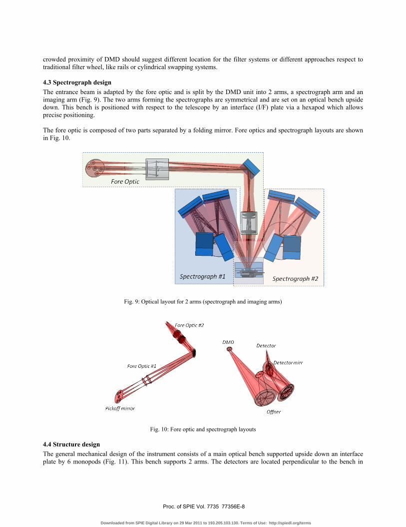
crowded proximity of DMD should suggest different location for the filter systems or different approaches respect to traditional filter wheel, like rails or cylindrical swapping systems. 4.3 Spectrograph design The entrance beam is adapted by the fore optic and is split by the DMD unit into 2 arms, a spectrograph arm and an imaging arm (Fig. 9). The two arms forming the spectrographs are symmetrical and are set on an optical bench upside down. This bench is positioned with respect to the telescope by an interface (I/F) plate via a hexapod which allows precise positioning. The fore optic is composed of two parts separated by a folding mirror. Fore optics and spectrograph layouts are shown in Fig. 10.
Fig. 9: Optical layout for 2 arms (spectrograph and imaging arms)
Fig. 10: Fore optic and spectrograph layouts 4.4 Structure design The general mechanical design of the instrument consists of a main optical bench supported upside down an interface plate by 6 monopods (Fig. 11). This bench supports 2 arms. The detectors are located perpendicular to the bench in
Proc. of SPIE Vol. 7735 77356E-8
Downloaded from SPIE Digital Library on 29 Mar 2011 to 193.205.103.130. Terms of Use: http://spiedl.org/terms

order to have an easier integration of the detectors. Covers around the instrument, i.e. linking the bench and the interface plate, protect the whole instrument (dust and straylight). Electronics boxes could also be located on top of the bench.
Fig. 11: 3D general design view The optomechanical mount presented on Figure 12 is just a concept and it will be detailed in future studies. The body of the support is made of aluminium alloy for compatibility of thermal contraction with the whole instrument. The mirrors are positioned in their isostatic frame; the settings are realized by stops and screws. The brackets are positioned and fixed on the optical bench through systems repositioning identical if taken out.
Fig. 12: Preliminary optomechanical mount concept
A hexapod is used to position the instrument following the 6 degrees of freedom and rigidly fix it onto the telescope interface. The positioning accuracy is of the order of a few hundredth of a millimeter to a magnitude limit of several tens of mm. 4.5 Materials In order to minimize cost, the design intends to use only one type of material which is aluminium alloy (except for mirrors that will be made in zerodur and monopods in stainless steel), aluminium/aluminium honey comb is also used for bench and I/F plate because of its stiffness and light weighting. 4.6 Overall volume and mass budget The mass of each element has been quickly estimated by taken into account classical density of material used. In addition, an overall system level margin provision of 20% has been taken.
Proc. of SPIE Vol. 7735 77356E-9
Downloaded from SPIE Digital Library on 29 Mar 2011 to 193.205.103.130. Terms of Use: http://spiedl.org/terms

Fig. 13: Overall envelope
Components Unit mass
(kg) # Total mass (kg) Total mass with 20%
margin (kg) Optical bench, I/F plate and cover Hexapod and I/F Fore optics #1 and #2 Spectrograph DMD unit Detector unit Electronic box Harness, Miscellaneous
10.0 15.0 25.0 20.0 5.0 30.0 2.0 10
1 1 1 2 1 2 4 1
10.0 15.0 25.0 40.0 5.0 60.0 8.0 10.0
12.0 18.0 30.0 48.0 6.0 72.0 10.0 12.0
Total 210.0 Table 3: mass budget
5. SYSTEM DESIGN: THE OBSERVATION MANAGER The DMD@TNG control software and Data Handling System (DHS) compose what we call the "Observation Manager". It will be in charge of commanding the DMD configuration, to collect engineering and auxiliary data, to store and handle the images archive via a relational database. It will be implemented in two phases. The first will mainly be focused on the development of low level routines aimed at easily drive the DMD electronics and produce FITS formatted images. The second phase will be devoted to the development of a multi-purpose client/server DHS which is able to communicate with the other TNG Observing System components. In particular the control software will be able: 1. to pass to the TNG scheduler the list of targets and observing plan; 2. to receive and sent "on-target", "to-next-target" and "abort" commands; 3. to access all the relevant auxiliary data, in particular the meteo info; 4. to build a FITS image file with all the relevant header keywords. The DHS will be able not only to store and browse the collected images and observation log, but it will also include components able to perform images automatic analysis, like image cleaning, un-dispersed image astrometry and objects photometry, spectra extraction. In particular there will be a dedicated task to select the objects more suitable to be observed in spectral mode. The algorithm will primarily minimize the number of overlapping spectra using the prism dispersion law, image PSF and object magnitude. The acceptable level of spectra blending will be a user defined
Proc. of SPIE Vol. 7735 77356E-10
Downloaded from SPIE Digital Library on 29 Mar 2011 to 193.205.103.130. Terms of Use: http://spiedl.org/terms

parameter. Some level of spectra analysis aimed at evaluating detection limit and to estimate the actual fraction of blended spectra will be included too. For example fields with an unacceptable number of blended objects could be marked for re-pointing using a different field angle. All the products will be transferred daytime to a repository in Bologna for detailed analysis. A MCS16 server will assure a flexible access from the internet to observation logs and data. A web interface similar to that developed for the REM17 telescope will be implemented.
Fig. 14: A schematic view f the Observation Manager
6. CONCLUSION Next-generation infrared astronomical instrumentation for ground-based and space telescopes could be based on MOEMS programmable slit masks for multi-object spectroscopy (MOS). This astronomical technique is used extensively to investigate the formation and evolution of galaxies. We propose to develop a DMD-based MOS demonstrator to be mounted on the Galileo telescope. A two-arm instrument has been designed for providing in parallel imaging and spectroscopic capabilities. The two arms as well as the fore-optics for converting the telescope F ratio to F/4 on the DMD are mounted on a common bench attached to the telescope interface thanks to a hexapod. Good optical quality on the DMD and the detectors has been reached. This DMD-based MOS demonstrator on the sky is of prime importance for characterizing the actual performance of this new family of instruments, as well as investigating the operational procedures on astronomical objects. This demonstrator will be studied in order to be placed on the Telescopio Nazionale Galileo during next year.
Proc. of SPIE Vol. 7735 77356E-11
Downloaded from SPIE Digital Library on 29 Mar 2011 to 193.205.103.130. Terms of Use: http://spiedl.org/terms

REFERENCES 1. R. Burg, P.Y. Bely, B. Woodruff, J. MacKenty, M. Stiavelli, S. Casertano, C. McCreight and A. Hoffman, "Yardstick integrated
science instrument module concept for NGST", in Proceedings of the SPIE conference on Space Telescope and Instruments V, SPIE 3356, 98-105, Kona, Hawaii, 1998
2. F. Zamkotsian, K. Dohlen, D. Burgarella, V. Buat, "Aspects of MMA for MOS: optical modeling and surface characterization, spectrograph optical design", in Proceedings of the NASA conference on "NGST Science and Technology Exposition", ASP Conf. Ser. 207, 218-224, Hyannis, USA, 1999
3. M. Robberto, A. Cimatti, A. Jacobsen, F. Zamkotsian, F. M. Zerbi, "Applications of DMDs for Astrophysical Research", in Proceedings of the SPIE conference on MOEMS 2009, Proc. SPIE 7210, San Jose, USA (2009)
4. H. Moseley, S. Aslam, M. Baylor, K. Blumenstock, R. Boucarut, A. Erwin, R. Fettig, D. Franz, T. Hadjimichael, J. Hein, A. Kutyrev, M. Li, D. Mott, C. Monroy, D. Schwinger "Microshutter arrays for the NGST NIRSpec", in Proceedings of the SPIE conference on Astronomical Telescopes and Instrumentation 2002, Proc. SPIE 4850, Hawaii, USA, 2002
5. S. Waldis, F. Zamkotsian, P. Lanzoni, W. Noell, N. de Rooij, "Micromirrors for multiobject spectroscopy: optical and cryogenic characterization", in Proceedings of the SPIE conference on MOEMS 2008, Proc. SPIE 6887, San Jose, USA (2008)
6. M. Canonica, S. Waldis, F. Zamkotsian, P. Lanzoni, W. Noell, N. de Rooij, " Development of MEMS-based programmable slit mask for multi-object spectroscopy ", in Proceedings of the SPIE conference on Astronomical Telescopes and Instrumentation, Proc. SPIE 7739, San Diego, USA (2010)
7. Kearney, K.J., Ninkov, Z., "Characterization of a digital micromirror device for use as an optical mask in imaging and spectroscopy, " Proc. SPIE 3292, 81-92 (1998)
8. MacKenty, J.W., Greenhouse, M.A., Green, R.F., Sparr, L., Ohl IV, R.G., Winsor, R.S., "IRMOS: an infrared multi-object spectrometer using a MEMS micro-mirror array, " Proc. SPIE 4841, 953 (2003)
9. Meyer, R.D., Kearney, K.J., Ninkov, Z., Cotton, C.T., Hammond, P., Statt, B.D., "RITMOS: a micromirror-based multi-object spectrometer, " Proc. SPIE 5492, 200 (2004)
10. Zamkotsian, F., Dohlen, K., Bulgarella, D., Buat, V., "Aspect of MMA for MOS: Optical Modeling and Surface Characterization, Spectrograph Optical Design, " Proc. ASP Conf. Series 207, 218 (2000)
11. Content, R., Cimatti, A., Robberto, M., Grange, R., Spanò, P., Sharples, R.M., Baugh, C., Garilli, B., Guzzo, L., Le Fevre, O., Maccagni, D., Rosati, P., Wang, Y., Zamorani, G., Zerbi, F.M., "Offspring of SPACE: the spectrograph channel of the ESA Dark Energy Mission EUCLID, " Proc. SPIE 7010, 70104S (2008)
12. Spanò, P., Zamkotsian, F., Content, R., Grange, R., Robberto, M., Valenziano, L., Zerbi, F. M., Sharples, R. M., Bortoletto, F., De Caprio, V., Martin, L., De Rosa, A., Franzetti, P., Diolaiti, E., Garilli, B., Guzzo, L., Leutenegger, P., Scodeggio, M., Vink, R., Zamorani, G., Cimatti, A., "DMD multi-object spectroscopy in space: the EUCLID study, " Proc. SPIE 7436, 74360O (2009)
13. F. Zamkotsian, K. Dohlen, "Performance modeling of JWST Near Infrared Multi-Object Spectrograph," in Proceedings of the SPIE conference on Astronomical Telescopes and Instrumentation 2004, Proc. SPIE 5487, Glasgow, United Kingdom (2004)
14. F. Zamkotsian, J. Gautier, P. Lanzoni, "Characterization of MOEMS devices for the instrumentation of Next Generation Space Telescope," in Proceedings of the SPIE conference on MOEMS 2003, Proc. SPIE 4980, San Jose, USA (2003)
15. F. Zamkotsian, P. Lanzoni, E. Grassi, R. Barette, C. Fabron, K. Tangen, L. Valenziano, L. Marchand, L. Duvet "Space evaluation of 2048x1080 mirrors DMD chip for ESA EUCLID mission," in Proceedings of the SPIE conference on Astronomical Telescopes and Instrumentation, Proc. SPIE 7731, San Diego, USA (2010)
16. Nicastro, L., Calderone, G., "A Customizable Database Server: MCS, a Flexible Resource for Astronomical Projects", Proc. of ADASS XVI, ASP Conf. Series v. 376, p. 323 (2007), astro-ph/0701260
17. Molinari, E., et al, "REM: automatic for the people", Advances in Astronomy, Vol. 2010, Article ID 253675 (2010)
Proc. of SPIE Vol. 7735 77356E-12
Downloaded from SPIE Digital Library on 29 Mar 2011 to 193.205.103.130. Terms of Use: http://spiedl.org/terms