DLT-V83 Series User Manual
178
DLT-V83 Series Industrial Computer Manual
Transcript of DLT-V83 Series User Manual

DLT-V83 Series
Industrial Computer
Manual

IMPORTANT:
For safe and proper use, follow these instructions.
Keep them for future reference.
Manual version
Manual version: V3.01
Completed on: June 15, 2021
Revision history (starting from DLT-V83 Facelift 2019):
Version Date Manual modifications
V2.10 August 22,
2019
Description of new DLT-V83 Facelift models DLT-V8310, DLT-V8312
and DLT-V8315.
Description IGX Tool updated.
V3.00 February 26,
2021
Update: Radio card SPARKLAN WPEQ-261ACN (BT) supports
Bluetooth Type 5.0.
Description of MPair application added.
Description of Sparklan WLAN driver added.
V3.01 June 15,
2021 Description of IGX Driver and Tool updated.
Copyright & Disclaimer
This document and the software and hardware included with this product are copyrighted
2019-2021 by Advantech Co., Ltd. All rights are reserved. This document is intended for
reference purposes only. All product specifications are subject to change without notice.
Advantech Co., Ltd. reserves the right to make improvements in this document in the
products described in this document at any time without notice. No part of this document
may be reproduced in any form or by any means, electronic, photocopying, recording,
translating, transmitting or otherwise, without prior written permission of Advantech Co.,
Ltd. Information provided in this document is intended to be accurate and reliable.
However, Advantech Co., Ltd. assumes no responsibility for its use, nor for any
infringements of the rights of third parties, which may result from its use.
Advantech Co., Ltd. assumes no liability for technical inaccuracies, typographic errors or
faults in this documentation. Advantech Co., Ltd. also assumes no liability for damages
caused directly or indirectly by the delivery, performance or usage of this material.
Note regarding all links and website content included in this document:
Advantech Co., Ltd. is not responsible for the accessibility of the websites and for the
content of external links contained in this document. The content and accessibility of the
linked websites are the sole responsibility of their operators.
Acknowledgements
The software and hardware designations as well as the brand names used in this
documentation are in most cases also registered trademarks and are subject to the
international law (trademark, brand and patent-protection laws). All product names or
trademarks are properties of their respective owners.
Windows® is a registered trademark of Microsoft Corporation in the United States (US)
and other countries.
Bluetooth® is a registered trademark of Bluetooth SIG, Inc. (Special Interest Group).
Intel® and Pentium® are registered trademarks of Intel Corp.
RAM® and RAM Mount™ are both trademarks of National Products Inc., 1205 S. Orr
Street, Seattle, WA 98108.
DLT-V83 Industrial Computers can be delivered with or without preinstalled software.
For devices with preinstalled software observe the associated license agreements.
FreeRTOS™ is a registered trademark of Real Time Engineers Ltd
(http://www.freertos.org). This product uses FreeRTOS. FreeRTOS is licensed with a
modified GNU GPL: http://www.freertos.org/a00114.html
The FreeRTOS source text is available from:
http://sourceforge.net/projects/freertos/files/FreeRTOS/V7.4.0/ or from Advantech.
Manufacturer
Advantech Co., Ltd.
No. 1, Alley 20, Lane 26, Rueiguang Road, Neihu District, Taipei 11491, Taiwan, R.O.C.
Simplified EU declaration of conformity
The manufacturer:
Advantech Co., Ltd.
No.1, Alley 20, Lane 26, Rueiguang Road, Neihu District, Taipei 11491, Taiwan, R.O.C.
The importer:
Advantech Service-IoT GmbH
Industriestrasse 15, 82110 Germering, Germany
Hereby declare that the following products
Product name: Industrial Computer
Model name: DLT-V83XXXXXXXXXXXXXX
Comply with the provisions of the applicable EU directives, including their amendments
applicable at the time of the declaration. For getting the detailed declarations of

conformity please visit our websites and contact your regional person in charge:
www.advantech.com / www.advantech.eu / www.advantech-service-iot.eu
Technical customer support
Contact your distributor, sales representative, or an Advantech Service Center for
technical support.
Please have the following information ready:
− Product name
− Serial number
− Description of your peripheral attachments
− Description of your software (operating system, application software, etc.)
− The exact wording of any error messages
− A complete description of the problem
Find the contact data of our Global Advantech Service Centers on our website:
http://erma.advantech.com
Initial inspection
Before setting up the system, check that the items listed below are included and in good
condition. If any item does not accord with the table, please contact your dealer
immediately:
• DLT-V83 Industrial Computer
• Cable cover and cable sealing set
• Product supplement
• Possibly “OS End User License Agreement” (depends on optional OS type)
If any of these items are missing or damaged, contact your distributor or sales
representative immediately. We have carefully inspected the device mechanically and
electrically before shipment. It should be free of marks and scratches and in perfect
working order upon receipt.
1. As you unpack the device, check it for signs of shipping damage. For example: box damage, scratches, dents, etc.
2. If it is damaged or it fails to meet the specifications, notify our service department or your local sales representative immediately.
3. Also, please notify the carrier. Retain the shipping carton and packing material for inspection by the carrier.

After inspection, we will make arrangements to repair or replace the unit.
A message to the customer
We want you to get the best performance possible from your products. If you run into
technical difficulties, we are here to help. For the most frequently asked questions, you
can easily find answers in your product documentation. These answers are normally a
lot more detailed than the ones we can give over the phone.
Please consult this manual first. If you still cannot find the answer, gather all the
information or questions that apply to your problem, and with the product close at hand,
call your dealer. Our dealers are well trained and ready to give you the support you need
to get the most from your Advantech products. In fact, most problems reported are minor
and can be easily solved over the phone.
In addition, free technical support is available from Advantech engineers every business
day. We are always ready to give advice about application requirements or specific
information on the installation and operation of any of our products.
FreeRTOS™ is a registered trademark of Real Time Engineers Ltd (http://www.freertos.org).
This product uses FreeRTOS. FreeRTOS is licensed with a modified GNU GPL
http://www.freertos.org/a00114.html.
The FreeRTOS source text is available from http://sourceforge.net/projects/freertos/files/FreeRTOS/V7.4.0/ or
from Advantech.
Manufacturer
Advantech Co., Ltd.
No. 1, Alley 20, Lane 26, Rueiguang Road, Neihu District, Taipei 11491, Taiwan, R.O.C.


Table of contents
1. Introduction .............................................................................................................................................. 5
1.1. Information about the DLT-V83 manuals ............................................................................................................. 5 1.1.1. Current manual versions ........................................................................................................................................... 5 1.1.2. Operating instructions for all device models ............................................................................................................. 5 1.1.3. Warnings and notes in the operating instructions ..................................................................................................... 6
2. Technical customer support .................................................................................................................. 7
3. Functional description ............................................................................................................................ 8
3.1. Intended use ........................................................................................................................................................ 8
3.2. Mount, operate and service the device correctly .................................................................................................. 9
3.3. Device identification / name plate ........................................................................................................................ 9
4. Unpacking, transporting, storing DLT-V83 ........................................................................................... 10
4.1. Unpacking ............................................................................................................................................................ 10
4.2. Transporting ......................................................................................................................................................... 10
4.3. Storage ................................................................................................................................................................. 11
5. Technical data of the device ................................................................................................................... 12
5.1. General ................................................................................................................................................................ 12 5.1.1. CPU, chipset, RAM, BIOS......................................................................................................................................... 12 5.1.2. Memory ..................................................................................................................................................................... 13 5.1.3. Housing, material, weight .......................................................................................................................................... 13 5.1.4. Display ...................................................................................................................................................................... 13 5.1.5. Environmental conditions .......................................................................................................................................... 14 5.1.6. Resistive touchscreen ............................................................................................................................................... 15 5.1.7. Projected-capacitive touchscreen (PCT) .................................................................................................................. 16 5.1.8. Device dimensions .................................................................................................................................................... 17 5.1.9. Internal speaker, sound............................................................................................................................................. 20
5.2. Power supply units, power supply ........................................................................................................................ 21 5.2.1. Integrated DC power supply unit ............................................................................................................................... 21 5.2.2. Integrated AC power supply unit ............................................................................................................................... 24
6. Technical data on radio modules ........................................................................................................... 27
6.1. Identification of the equipment variants ................................................................................................................ 27
6.2. Radio cards .......................................................................................................................................................... 27 6.2.1. Available radio cards for WLAN ................................................................................................................................ 27 6.2.2. Available Radio cards for WWAN ............................................................................................................................. 29
6.3. Antennas .............................................................................................................................................................. 30 6.3.1. WLAN antenna diversity, low profile IEEE 802.11 a/b/g/n ........................................................................................ 30 6.3.2. WLAN antenna IEEE 802.11 a/b/g/n/ac .................................................................................................................... 31 6.3.3. WLAN, WWAN 3G .................................................................................................................................................... 32 6.3.4. WLAN, WWAN, LTE 4G antenna (Multiband) .......................................................................................................... 33 6.3.5. External WLAN antenna IEEE 802.11 a/b/g/n .......................................................................................................... 34 6.3.6. External WWAN antenna 3G .................................................................................................................................... 35 6.3.7. External WWAN antenna 2G, 3G, 4G ....................................................................................................................... 36
6.4. Bluetooth (optional) .............................................................................................................................................. 37 6.4.1. Bluetooth integrated: WLAN card SPARKLAN WPEQ-261ACN (BT) ...................................................................... 37 6.4.2. Micro Bluetooth adapter (USB stick) ......................................................................................................................... 37
6.5. GPS receiver external (optional) .......................................................................................................................... 38
7. Interfaces, connectors ............................................................................................................................ 39
7.1. Integrated ............................................................................................................................................................. 39 7.1.1. LCD interface ............................................................................................................................................................ 39 7.1.2. Touch interface ......................................................................................................................................................... 39
7.2. External ................................................................................................................................................................ 40

7.2.1. Serial interfaces ........................................................................................................................................................ 40 7.2.2. USB, Service-USB .................................................................................................................................................... 40 7.2.3. Audio interface for handset ....................................................................................................................................... 40 7.2.4. Network interface ...................................................................................................................................................... 40
7.3. Serial interfaces - Functions ................................................................................................................................. 41 7.3.1. COM1 as a voltage source (optional) ....................................................................................................................... 41 7.3.2. COM2 as EIA-422/485 (optional) .............................................................................................................................. 41 7.3.3. Network adapter (10/100/1000) ................................................................................................................................ 41 7.3.4. CAN, digital I/O and second Ethernet interface (optional) ........................................................................................ 42 7.3.5. Serial interface barcode scanners ............................................................................................................................ 44 7.3.6. Tips & tricks ............................................................................................................................................................... 44
7.4. Connections under the cable cover ...................................................................................................................... 45 7.4.1. DC devices: connections, expansion interfaces ....................................................................................................... 45 7.4.2. AC devices (DLT-V8315 only): connections, expansion interfaces .......................................................................... 46
7.5. Connections underneath the antenna/protective cap ........................................................................................... 47 7.5.1. Information on service USB, CFast and Mini SIM card slot ...................................................................................... 47
8. Open/close antenna (or protective cap) ................................................................................................ 48
8.1. Avoid Property damage ........................................................................................................................................ 48 8.1.1. Disconnecting from the electric power source .......................................................................................................... 48 8.1.2. Tools required ........................................................................................................................................................... 48
8.2. Open/close protective cap .................................................................................................................................... 49
8.3. Open/close antenna ............................................................................................................................................. 49 8.3.1. WLAN antenna IEEE 802.11 a/b/g/n ........................................................................................................................ 49 8.3.2. WLAN antenna IEEE 802.11 a/b/g/n/ac .................................................................................................................... 50 8.3.3. WLAN, WWAN 3G antenna ...................................................................................................................................... 51 8.3.4. WLAN, WWAN antenna (multi-band) LTE 4G .......................................................................................................... 52
9. Operating the device ............................................................................................................................... 54
9.1. Safety notes for normal operation, control ........................................................................................................... 54
9.2. Switching the DLT-V83 on/off .............................................................................................................................. 56
9.3. Operating the touchscreen ................................................................................................................................... 56 9.3.1. Prevent damage to the touchscreen ......................................................................................................................... 57 9.3.2. Operating the resistive touchscreen ......................................................................................................................... 57 9.3.3. Operating the PCT touchscreen ............................................................................................................................... 57
9.4. DLT-V83 front keys with resistive touchscreen .................................................................................................... 58 9.4.1. Overview of the operating elements on the device front ........................................................................................... 58 9.4.2. Device with 26 front keys .......................................................................................................................................... 59 9.4.3. Device with 5 front keys ............................................................................................................................................ 61 9.4.4. Operating states ........................................................................................................................................................ 62
9.5. DLT-V83 front keys with PCT touchscreen .......................................................................................................... 63 9.5.1. Overview of the operating elements on the front side .............................................................................................. 63 9.5.2. Function of the front keys .......................................................................................................................................... 63 9.5.3. Operating states ........................................................................................................................................................ 64
9.6. Software keyboard (optional) ............................................................................................................................... 65
10. General device configuration ................................................................................................................. 66
10.1. Operating systems (optional) ............................................................................................................................... 66
10.2. Image compatibility of varying CPUs ................................................................................................................... 66
10.3. Linux OS (optional) .............................................................................................................................................. 66
10.4. MS-Windows OS (optional) .................................................................................................................................. 67 10.4.1. Setting up MS-Windows ...................................................................................................................................... 67 10.4.2. USB recovery stick .............................................................................................................................................. 67 10.4.3. WES 7 and Win 7 Prof.: USB icon in the taskbar ............................................................................................... 67
10.5. Configuring the front keys, automatic shutdown, etc. .......................................................................................... 68
10.6. Automatic shutdown ............................................................................................................................................. 69 10.6.1. Functional description ......................................................................................................................................... 69 10.6.2. Sequence ............................................................................................................................................................ 69

10.7. CAN and digital I/O settings (optional) ................................................................................................................. 70 10.7.1. iManager ............................................................................................................................................................. 71
10.8. Protecting the display from the memory effect ..................................................................................................... 72
10.9. (Re)calibrating the touchscreen ........................................................................................................................... 72
10.10. ErP settings for AC devices ................................................................................................................................. 73 10.10.1. BIOS settings in order to deactivate WakeOnLAN ............................................................................................. 73 10.10.2. MS-Windows settings for deactivating WakeOnLAN .......................................................................................... 73 10.10.3. Power options...................................................................................................................................................... 74
10.11. MPair .................................................................................................................................................................... 75
11. WLAN configuration ................................................................................................................................ 76
11.1. Safety notice ........................................................................................................................................................ 76
11.2. Differences between MS Windows and Linux ...................................................................................................... 77
11.3. Preparation work at the factory ............................................................................................................................ 77
11.4. Customer-specific settings ................................................................................................................................... 78
11.5. Windows Zero Configuration (WZC) .................................................................................................................... 78
11.6. Sparklan WLAN driver .......................................................................................................................................... 79 11.6.1. Area of application .............................................................................................................................................. 79 11.6.2. Requirements ...................................................................................................................................................... 79 11.6.3. After image reinstallation: Driver installation ....................................................................................................... 80 11.6.4. “Standard” Driver installation WinEmbStd7 / Win7Pro / Win 10 IoTEnt .............................................................. 80 11.6.5. Sparklan “Roaming” Setting ................................................................................................................................ 83
11.7. Sparklan BT driver ............................................................................................................................................... 85 11.7.1. Area of application .............................................................................................................................................. 85 11.7.2. Requirements ...................................................................................................................................................... 85 11.7.3. After image reinstallation: Driver installation ....................................................................................................... 86 11.7.4. “Standard” Driver installation Win10IoTEnt ......................................................................................................... 86
11.8. Advantech WLAN Client Manager (IGX Tool) ...................................................................................................... 90 11.8.1. Area of application .............................................................................................................................................. 90 11.8.2. Program version 1.01 (new features) .................................................................................................................. 90 11.8.3. Program version 1.02 (new features) .................................................................................................................. 90 11.8.4. Driver download .................................................................................................................................................. 90 11.8.5. After image reinstallation: Driver installation ....................................................................................................... 91 11.8.6. “Silent” Driver installation WES7 / Win7Pro / Win10IoTEnt ................................................................................ 91 11.8.7. “Silent” Driver uninstaller WES7 / Win7Pro / Win10IoTEnt ................................................................................. 91 11.8.8. Start WLAN Client Manager, Login ..................................................................................................................... 92 11.8.9. WLAN Client Manager functions ......................................................................................................................... 95 11.8.10. Browse nearby wireless networks ....................................................................................................................... 96 11.8.11. Roam Management ............................................................................................................................................. 103 11.8.12. Import / Export feature ........................................................................................................................................ 109
11.9. Laird Connection Manager (LCM) ........................................................................................................................ 114
12. WWAN configuration ............................................................................................................................... 116
12.1. Safety notice ........................................................................................................................................................ 116
12.2. Differences between MS Windows and Linux ...................................................................................................... 117
12.3. Preparation work at the factory (DLT-V83 delivery status) .................................................................................. 117
12.4. SIM card for WWAN (customer-specific).............................................................................................................. 118
12.5. Configuration of radio card SIERRA WIRELESS MC80 ...................................................................................... 118 12.5.1. Open device manager ......................................................................................................................................... 119 12.5.2. Establish Internet connection .............................................................................................................................. 119 12.5.3. SIERRA WIRELESS MC80 Trouble Shooting .................................................................................................... 122
12.6. Configuration of Radio card QUECTEL EC25 ..................................................................................................... 125 12.6.1. Establish Internet connection .............................................................................................................................. 125 12.6.2. QUECTEL EC25 Trouble Shooting ..................................................................................................................... 128
13. Mechanical mounting .............................................................................................................................. 131
13.1. Warning about injuries and Property damage ...................................................................................................... 131 13.1.1. Important: Installation of the DLT-V83 on vehicles ............................................................................................. 132

13.2. Overview of mounting steps ................................................................................................................................. 133
13.3. Connecting external accessories to the DLT-V83 ................................................................................................ 133
13.4. Attaching device mounting and accessory mounting (optional) ........................................................................... 134 13.4.1. VESA drill holes................................................................................................................................................... 134
14. Electrical connection .............................................................................................................................. 137
14.1. Connection to the power supply ........................................................................................................................... 137
14.2. Connecting DC devices to the power supply ....................................................................................................... 138 14.2.1. Important: Electrical connection of the DLT-V83 to vehicles .............................................................................. 139 14.2.2. Electrical installation of DC devices .................................................................................................................... 139 14.2.3. Electrically isolated installation of DC devices .................................................................................................... 140
14.3. Connecting AC devices to the power supply ........................................................................................................ 141 14.3.1. Electrical installation of AC devices .................................................................................................................... 141
15. Attaching cables and the cable cover ................................................................................................... 142
15.1. Overview of mounting steps ................................................................................................................................. 142
15.2. Required components .......................................................................................................................................... 143
15.3. Attaching cable grommets and fixing strain relief in place ................................................................................... 144 15.3.1. Attaching the cable cover (without integrated UPS) ........................................................................................... 147 15.3.2. Attaching the cable cover (with integrated UPS) ................................................................................................ 147
15.4. Pressure compensation element .......................................................................................................................... 148
16. Optional equipment/accessories ........................................................................................................... 149
16.1. Integrated UPS (optional) ..................................................................................................................................... 149 16.1.1. UPS Battery pack specification ........................................................................................................................... 150 16.1.2. Charging the integrated UPS correctly................................................................................................................ 151 16.1.3. No repair/replacement of the battery packs ........................................................................................................ 151
16.2. Screen-Defroster (optional) .................................................................................................................................. 151
16.3. Pre-converter and power cables (optional) .......................................................................................................... 152
16.4. Voice Kit (optional) ............................................................................................................................................... 152
16.5. Terminal mountings (optional) .............................................................................................................................. 153
16.6. Keyboards and keyboard holders (optional) ........................................................................................................ 153
16.7. Stylus for touchscreens (optional) ........................................................................................................................ 154
16.8. External CD/DVD-ROM drive (optional) ............................................................................................................... 154
16.9. USB recovery stick (optional) ............................................................................................................................... 155
16.10. Scanner and scanner bracket (optional) .............................................................................................................. 155
16.11. Sun visor (optional) .............................................................................................................................................. 155
16.12. Protective film for touchscreen (optional) ............................................................................................................. 155
17. Maintenance, Cleaning ............................................................................................................................ 156
17.1. Manufacturer, authorized service centers ............................................................................................................ 156
17.2. No repair/replacement of the battery packs ......................................................................................................... 156
17.3. Regular checks and maintenance of the complete system .................................................................................. 156
17.4. Cleaning the device .............................................................................................................................................. 157 17.4.1. Cleaning the housing .......................................................................................................................................... 157 17.4.2. Cleaning the touchscreen ................................................................................................................................... 157
17.5. Touchscreen protective film (optional) ................................................................................................................. 158
18. Malfunctions ............................................................................................................................................ 159
19. Reasonably foreseeable misuse ............................................................................................................ 161
19.1. General ................................................................................................................................................................ 161
19.2. Mobile application on vehicles ............................................................................................................................. 161
19.3. Stationary use with AC power supply unit ............................................................................................................ 161

20. Guidelines and certificates ..................................................................................................................... 162
20.1. Simplified EU declaration of conformity ............................................................................................................... 162
20.2. Low-voltage guidelines ......................................................................................................................................... 162
20.3. EMC guidelines .................................................................................................................................................... 162 20.3.1. Shielded components .......................................................................................................................................... 162 20.3.2. EMC EU .............................................................................................................................................................. 162 20.3.3. FCC USA ............................................................................................................................................................. 162 20.3.4. ICES Canada ...................................................................................................................................................... 163
20.4. RoHS Directive EU ............................................................................................................................................... 163
20.5. RED (Radio Equipment Directive) 2014/53/EU .................................................................................................... 164
20.6. Eco-design directive (2009/125/EC) .................................................................................................................... 165
20.7. CE marking .......................................................................................................................................................... 165
20.8. CCC, SRRC China ............................................................................................................................................... 165
20.9. CNROHS .............................................................................................................................................................. 166
20.10. MIC Japan (previously TELEC) ............................................................................................................................ 166
21. Recycling information ............................................................................................................................. 167
22. List of figures ........................................................................................................................................... 168

Introduction
DLT-V83 Manual V3.00 5 / 178
1. Introduction
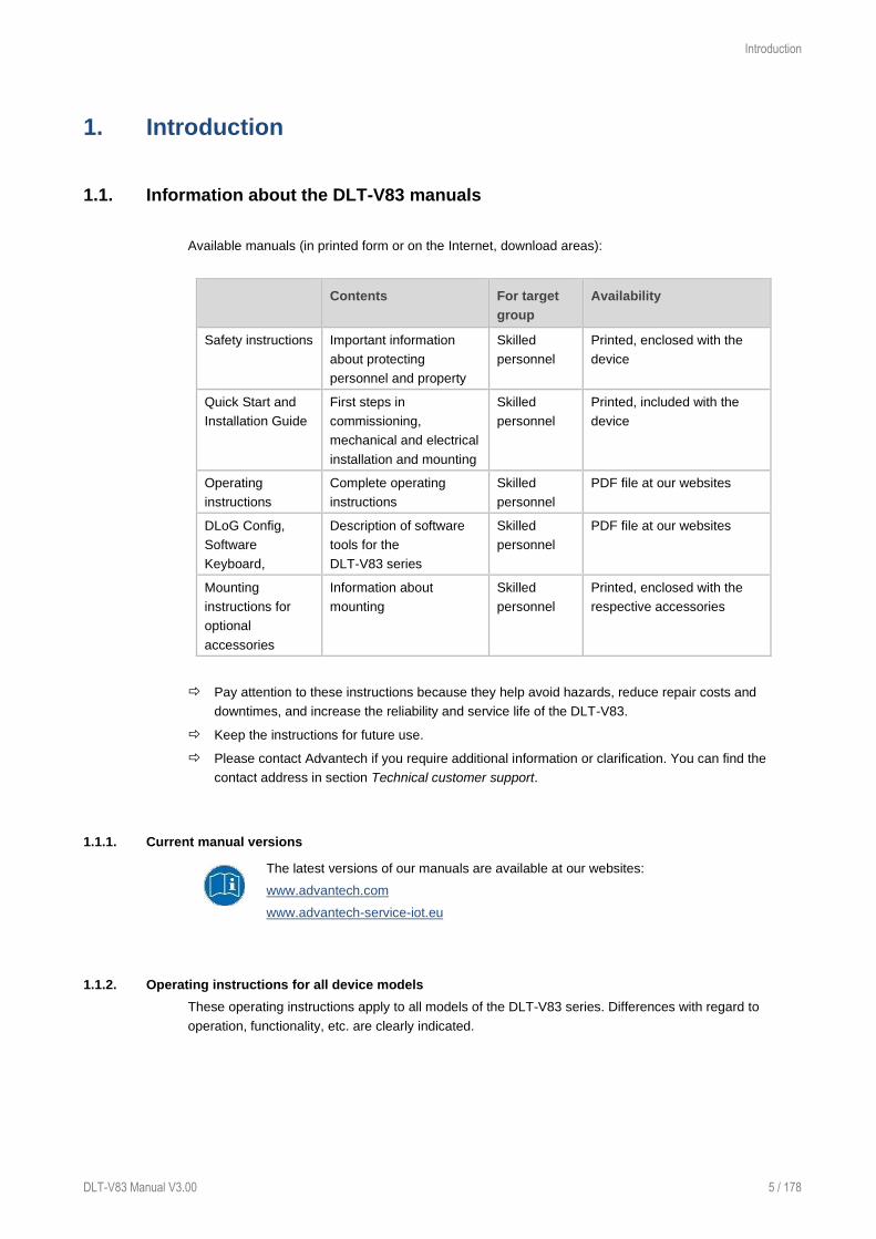
1.1. Information about the DLT-V83 manuals
Available manuals (in printed form or on the Internet, download areas):
Contents For target
group
Availability
Safety instructions Important information
about protecting
personnel and property
Skilled
personnel
Printed, enclosed with the
device
Quick Start and
Installation Guide
First steps in
commissioning,
mechanical and electrical
installation and mounting
Skilled
personnel
Printed, included with the
device
Operating
instructions
Complete operating
instructions
Skilled
personnel
PDF file at our websites
DLoG Config,
Software
Keyboard,
Description of software
tools for the
DLT-V83 series
Skilled
personnel
PDF file at our websites
Mounting
instructions for
optional
accessories
Information about
mounting
Skilled
personnel
Printed, enclosed with the
respective accessories
Pay attention to these instructions because they help avoid hazards, reduce repair costs and
downtimes, and increase the reliability and service life of the DLT-V83.
Keep the instructions for future use.
Please contact Advantech if you require additional information or clarification. You can find the
contact address in section Technical customer support.
1.1.1. Current manual versions
The latest versions of our manuals are available at our websites:
www.advantech.com
www.advantech-service-iot.eu
1.1.2. Operating instructions for all device models
These operating instructions apply to all models of the DLT-V83 series. Differences with regard to
operation, functionality, etc. are clearly indicated.

Introduction
6 / 178 DLT-V83 Manual V3.01
1.1.3. Warnings and notes in the operating instructions
Personal injury
Information with regard to personal injury is shown as follows (signal words for indicating risk level):
DANGER / WARNING / CAUTION
DANGER means that death or severe bodily injury will occur if this information is not observed.
WARNING means that death or severe bodily injury can occur if this information is not
observed.
CAUTION means that slight bodily injury can occur if this information is not observed.
Property damage
Information about Property damage is shown as follows:
NOTICE: Property damage
Information about possible Property damage.
Tips for handling product and operating instructions
Tips for handling product and operating instructions are shown as follows:
TIP
Tips for using the product.
Note about additional information in operating instructions.

Technical customer support
DLT-V83 Manual V3.00 7 / 178
2. Technical customer support
Contact your distributor, sales representative, or an Advantech Service Center for technical support.
Please have the following information ready:
− Product name
− Serial number
− Description of your peripheral attachments
− Description of your software (operating system, application software, etc.)
− The exact wording of any error messages
− A complete description of the problem
Find the contact data of our Global Advantech Service Centers on website:
http://erma.advantech.com

Functional description
8 / 178 DLT-V83 Manual V3.01
3. Functional description
3.1. Intended use
DLT-V83 Industrial Computers are data
communication terminals for use in
commercial environments (e.g. logistics,
warehousing, manufacturing). Any other
or additional use beyond this shall be
deemed an improper use. The
user/operator of the DLT-V83 is solely
responsible for any resulting damage.
This also applies to any unauthorized
modifications made to the device.
Indented use includes the compliance
with all safety instructions and the
compliance with the approved
environmental conditions and
specifications for the device.
The DLT-V83 Industrial Computers:
− are not approved for use in EX zones (potential explosion hazard).
− are not approved for use on ships.
− are not approved for use on railed vehicles.
− are not approved for use in life-support systems or critical safety systems where system malfunction
can lead to the direct or indirect endangerment of human life.
Accessories
Only use accessories that have been tested and approved for the respective DLT-V83. Otherwise, any
warranty for this device will be void.
Requirements for safe operation
The requirements are:
− Proper transport and storage.
− Proper setup and use.
− Proper maintenance and service.
− Operation by trained personnel.

Functional description
DLT-V83 Manual V3.00 9 / 178
3.2. Mount, operate and service the device correctly
DLT-V83 Industrial Computers were designed and built according to modern technology and accepted
safety regulations.
However, the operation of the DLT-V83 can endanger personnel or third parties and cause damage to
the device and other material assets when, for example, the device is:
− installed incorrectly or configured improperly.
− operated by untrained or uninstructed personnel.
− improperly operated and maintained.
− not used as intended.
The owner/operator commitments with regards to safety (accident prevention regulations, occupational
safety) are to be followed.
3.3. Device identification / name plate
The name plate on the rear side of the DLT-V83 must be legible at all times.
Do not damage the name plate or remove it from the device.
Information on the labels on the device (examples):
− Model name, e.g. DLT-V8310, DLT-V8312, DLT-V8315
− Serial number
− FCC ID (Radio)
− Barcode for internal use only

Unpacking, transporting, storing DLT-V83
10 / 178 DLT-V83 Manual V3.01
4. Unpacking, transporting, storing DLT-V83
4.1. Unpacking
Open the packaging carefully.
Save the packaging material (for possible forwarding transports or returns of the DLT-V83).
Check the shipment for completeness and any possible damage.
Always keep the supplied operating instructions and documents.
4.2. Transporting
WARNING
Personal injury from battery packs: Short-circuit, fire, chemical burns, toxic substances.
Devices with integrated UPS (optional) contain lithium-ion battery packs (hereinafter referred to
as: battery packs). These can ignite if handled improperly (risk of fire), cause chemical burns or
release toxic substances.
Be careful when handling battery packs.
Do not drop or damage battery packs.
Do not allow water or other liquids to come into contact with the device (exercise particular
caution with corrosive liquids).
Risk of injury due to the weight of the device.
The DLT-V83 can fall down and cause injuries due to its weight.
Always hold the DLT-V83 by the housing with both hands.
Never use the antenna cap as a handle. It can break due to the weight involved.
Use the assistance of a second person for installation work.
Risk of injury due to sharp-edged parts on the device.
The strain relief rail of the DLT-V83 can have sharp edges and cause cutting injuries.
Do not hold the DLT-V83 by the strain relief rail.
If a return/repacking is necessary
If the DLT-V83 is being returned to the manufacturer, a completely filled-out return shipment
form must be enclosed with every DLT-V83.
You can find the return shipment form at the end of this operating instructions and on our
websites.
Repackage the device using suitable packaging material to ensure that the device is not
damaged during transport.
For devices with integrated UPS/battery packs, comply with the transport conditions for
battery packs.
Use the required package labels and accompanying documents.

Unpacking, transporting, storing DLT-V83
DLT-V83 Manual V3.00 11 / 178
4.3. Storage
WARNING
Personal injury from battery packs: Short-circuit, fire, chemical burns, toxic substances.
Devices with integrated UPS/battery packs can ignite if stored improperly (risk of fire), cause
chemical burns or release toxic substances.
Store the cable cover with battery packs separately from the DLT-V83 device.
Handle the cable cover with battery packs carefully; do not damage; do not drill through
and do not crush or drop.
Store segregated, separate from acids and other materials.
Store in a cool, dry place.
Comply with the specified environmental conditions for storage.
Provide for sufficient ventilation of the storage location.
Do not allow water or other liquids to come into contact with the device (exercise particular
caution with corrosive liquids).
Do not store the device near sources of heat or fire, open flames or heaters.
Do not allow it to come into contact with fire.
Have suitable fire extinguishers ready (foam or powder) in accordance with safety
regulations.
Prevent Property damage due to deep discharge
Storing the battery packs incorrectly will cause them to discharge completely (deep discharge) and thus
damage them irreparably.
Place the DLT-V83 into operation within 3 (three) months after receiving it.
Charge the integrated battery packs by connecting the DLT-V83 to the power supply.
If you are not placing the DLT-V83 into operation within 6 (six) months, make sure you charge it
intermediately.
Protecting touchscreens from damage
Protect touchscreens from sharp edges, impacts, and heavy objects.
If stacking, do not stack higher than four devices.
Place devices front-to-front in this case. The VESA mounting point on the rear side of the device
can damage the touchscreen of another device.
Use protective material (non-flammable!) between the devices as a precaution.

Technical data of the device
12 / 178 DLT-V83 Manual V3.01
5. Technical data of the device
5.1. General
5.1.1. CPU, chipset, RAM, BIOS
Intel® Atom™ D525 processor 1.80 GHz (dual core)
CPU
Chipset
Cache
Intel® Atom™ D525 processor
1.80 GHz (dual core)
800 MHz Front Side Bus (FSB) and 800 MHz memory bus speed,
1 MB L2 cache, 45 nm
System chipset Intel®ICH8M
RAM Up to 4 GB
DDR3 technology
BIOS AMIBIOS8® - Flash BIOS with ACPI, PnP
Programmable in the system, BIOS POST self-test
Real-time clock Real-time clock with a power reserve of up to 5 years
Intel® Core™ i5-4300U processor (4th Generation Intel® Core™ i5)
CPU
Chipset
Cache
Intel® Core™ i5-4300U (4th Generation Intel® Core™ i5)
1.90 GHz (dual core)
Max. 2.9 GHz turbo clock rate
DDR3L 1600
Intel® Smart Cache 3 MB, 22 nm
RAM Up to 16 GB
DDR3L technology
BIOS AMI UEFI BIOS @ 128 Mb
Programmable in the system, BIOS POST self-test
Real-time clock Real-time clock with a power reserve of up to 5 years
Intel® Celeron® 2980U processor
CPU
Chipset
Cache
Intel® Celeron® 2980U
1.60 GHz (dual core)
DDR3L 1600
Intel® Smart Cache 2 MB, 22 nm
RAM Up to 8 GB
DDR3L technology
BIOS AMI UEFI BIOS @ 128 Mb
Programmable in the system, BIOS POST self-test
Real-time clock Real-time clock with a power reserve of up to 5 years

Technical data of the device
DLT-V83 Manual V3.00 13 / 178
5.1.2. Memory
CFast SLC technology Optional, based on SLC technology (single level cell)
CFast MLC technology Optional, based on MLC technology (multi-level cell)
SSD 2,5“ Optional, based on MLC technology (multi-level cell)
5.1.3. Housing, material, weight
Material Rugged aluminum-cast housing
ESD safe
Weight DLT-V8310: 4 kg
DLT-V8312: 5.5 kg
DLT-V8315: 6.4 kg
Dimensions See Chapter 5.1.8 Device dimension
5.1.4. Display
DLT-V8310 10.4“ SVGA 800 x 600, 400 cd/m2
Brightness control
Or:
10,4“ XGA 1024 x 768, 400 cd/m²
Brightness control
DLT-V8312 12.1" XGA 1024 x 768, 500 cd/m2
Brightness control
DLT-V8315 15" XGA 1024 x 768, 400 cd/m2
Brightness control
The LCD display of the DLT-V83 series fulfills the highest quality standards and was inspected for pixel
defects. However, due to technological reasons pixel defects can occur.
This is not a malfunction; it is a part of the technical specifications.

Technical data of the device
14 / 178 DLT-V83 Manual V3.01
5.1.5. Environmental conditions
DLT-V83 without integrated UPS
Operating temperature -30 to +50 °C
Specification according to EN 60068-2-1/2
Storage temperature -30 to +65 °C
Specification according to EN 60068-2-1/2
Relative humidity 10% to 90% at 40 °C relative humidity, noncondensing
Specification according to EN 60068-2-3
Mechanical vibration
and shock resistance DLT-V8310 and DLT-V8312:
− Class 5M3 according to EN 60721-3-5
− US Highway Truck according to MIL-STD 810F
DLT-V8315:
− Class 5M2 according to EN 60721-3-5
− US Highway Truck according to MIL-STD 810F
DLT-V83 with integrated UPS (optional)
Operating temperature -10 to +50 °C
Charging temperature 0 to +45 °C (internal device temperature)
Storage temperature -20 to +60 °C; specification according to EN 60068-2-1/2
Relative humidity 10% to 90% at 40 °C relative humidity, noncondensing;
specification according to EN 60068-2-3
Mechanical vibration
and shock resistance DLT-V8310 and DLT-V8312:
− Class 5M3 according to EN 60721-3-5
− US Highway Truck according to MIL-STD 810F
DLT-V8315:
− Class 5M2 according to EN 60721-3-5,
− US Highway Truck according to MIL-STD 810F

Technical data of the device
DLT-V83 Manual V3.00 15 / 178
5.1.6. Resistive touchscreen
Standard version
DLT-V8310
Type 4-wire analog resistive touchscreen
Construction Device without Screen-Defroster: Film-Film-Glass (FFG), fully laminated
front.
Device with Screen-Defroster: Buffer-film-film-glass heater
Resistance Chemically hardened glass
Hardness of
surface
JIS-K-5400: 3 H at 750 g
Shock resistance IK08 according to IEC 62262
Mechanical
resistance
Tapping: > 1 million times with rubber test pen
Swiping: > 100,000 times with polydactyl pen
Resistance to
industrial
chemicals
Alcohols, dilute acids, dilute alkalis, esters, hydrocarbons, ketones,
household cleaning agents (according to DIN 42 115)
DLT-V8312 and DLT-V8315
Type 8-wire analog resistive touchscreen
Construction Device without Screen-Defroster: Film-Film-Glass (FFG), fully laminated
front.
Device with Screen-Defroster: Buffer-film-film-glass heater
Resistance Chemically hardened glass
Hardness of
surface
JIS-K-5400: 3 H at 750 g
Shock resistance IK08 according to IEC 62262
Mechanical
resistance
Tapping: > 5 million times with rubber test pen
Swiping: > 100,000 times with polydactyl pen
Resistance to
industrial
chemicals
Alcohols, dilute acids, dilute alkalis, esters, hydrocarbons, ketones,
household cleaning agents (according to DIN 42 115)

Technical data of the device
16 / 178 DLT-V83 Manual V3.01
Sunlight readable touchscreen version (optional)
Sunlight readable touchscreen
Type 5-wire analog resistive touchscreen
Construction Film-Glass (FG), chemically toughened glass
Hardness of surface JIS-K-5400: 1 H at 750 g
Shock resistance IK08 according to IEC 62262
Mechanical resistance Tapping: > 10 million times with rubber test pen
Swiping: > 100,000 times with polydactyl pen
Chemical resistance to
industrial chemicals
Hydrogen peroxide, iso alcohol 50 5, iso alcohol 70%, mineral
spirits, gasoline, motor oil, diesel fuel, transmission fluid, brake
fluid, antifreeze, hydraulic oil, bleach, ethanol, turpentine, acetone,
“diethylene glycol monoethyl ether acetate“, toluene, petroleum
ether, hydrochloric acid, glycol ether acetate, MEK, heptane,
sodium hydroxide
5.1.7. Projected-capacitive touchscreen (PCT)
Some DLT-V83 device models are available optionally with a PCT, for example:
− DLT-V8310 XGA with 9 front keys
− DLT-V8310 SVGA with 9 front keys
− DLT-V8312 with 9 front keys
− DLT-V8315 with 9 front keys
PCT touchscreen
Type Projected-capacitive touchscreen
Construction Glass film
Hardness of surface Hardness JIS-K-5400: > 10 H at 750 g
Shock resistance IK08 according to IEC 62262
Chemical AR coated glass with gloss value 60 according to
ISO 2813, 7668; ASTM D 523, D 2457; DIN 67539
Mechanical properties Thermally pre-stressed, acid-etched planibel float glass
Chemical resistance Resistant to chemicals.
Not resistant to strong acids, gasoline and diesel.

Technical data of the device
DLT-V83 Manual V3.00 17 / 178
5.1.8. Device dimensions
DLT-V8310
Dimensions without add-ons (in mm)
Fig. 5.1: Dimensions DLT-V8310
The building depth of the DLT-V8310 varies depending on the type of touchscreen:
Device type Building depth
(Mass X, see figure)
DLT-V8310 standard resistive touchscreen 90,0 mm
DLT-V8310 sunlight readable resistive touchscreen 90,0 mm
DLT-V8310 PCT touchscreen 91,5 mm
DLT-V8310 with screen-defroster front 90,7 mm

Technical data of the device
18 / 178 DLT-V83 Manual V3.01
DLT-V8312
Dimensions without add-ons (in mm)
Fig. 5.2: Dimensions DLT-V8312
The building depth of the DLT-V8312 varies depending on the type of touchscreen:
Device type Building depth
(Mass X, see figure)
DLT-V8312 standard resistive touchscreen 93,0 mm
DLT-V8312 sunlight readable resistive touchscreen 94,7 mm
DLT-V8312 PCT touchscreen 96,0 mm
DLT-V8312 with screen-defroster front 94,2 mm

Technical data of the device
DLT-V83 Manual V3.00 19 / 178
DLT-V8315
Dimensions without add-ons (in mm)
Fig. 5.3: Dimensions DLT-V8315
The building depth of the DLT-V8315 varies depending on the type of touchscreen:
Device type Building depth
(Mass X, see figure)
DLT-V8315 standard resistive touchscreen 98 mm
DLT-V8315 PCT touchscreen 97 mm

Technical data of the device
20 / 178 DLT-V83 Manual V3.01
5.1.9. Internal speaker, sound
The DLT-V83 is equipped with an internal speaker as standard (2 W).
The system messages from the Industrial Computer are output via this speaker.
The internal speaker is configured in the audio settings for the operating system in question.
Fig. 5.4: Internal speaker position
Technical data of the device
DLT-V83 Manual V3.00 21 / 178
5.2. Power supply units, power supply
5.2.1. Integrated DC power supply unit
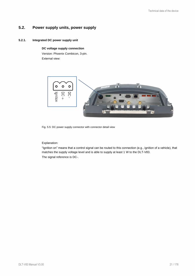
DC voltage supply connection
Version: Phoenix Combicon, 3-pin.
External view:
Fig. 5.5: DC power supply connector with connector detail view
Explanation:
“Ignition on” means that a control signal can be routed to this connection (e.g., ignition of a vehicle), that
matches the supply voltage level and is able to supply at least 1 W to the DLT-V83.
The signal reference is DC-.

Technical data of the device
22 / 178 DLT-V83 Manual V3.01
Power supply, power consumption, power supply unit fuses
Power supply
DC power pack
12/24/48 VDC
(wide-range power supply
unit)
60 W / 80 W internal
Type DC-16
12/24/48 VDC nominal
Galvanically isolated
Withstands bursts up to 2 kV
Full output power of the 12/24/48 VDC power supply unit for 20
seconds each:
For 6 V: 40 W
For 9 V: 60 W
Rising in linear fashion between the above
Voltage range 9 to 60 VDC
Bridged power failures Typically 2 ms at 12 V
Typically 10 ms at 24 V
Typically 40 ms at 48 V
Maximum output power 60 W (+10 to +70 °C internal device temperature);
or 80 W (-30 to +10 °C internal device temperature)
Nominal current 8.4 A
Connection to SELV circuit
only
The SELV circuit is a secondary circuit that is designed and
protected so that its voltages will not exceed a safe value both
when operating correctly or if a single error occurs.
Power consumption DLT-V83 Intel® Atom™ D525
DLT-V8310 Typically 25 W, Standby typically 1 W
DLT-V8312 Typically 30 W, Standby typically 1 W
DLT-V8315 Typically 30 W, Standby typically 1 W
Power consumption DLT-V83 Intel® Core™ i5-4300U and Intel® Celeron® 2980U
DLT-V8310 Typically 35 W, Standby typically 1 W
DLT-V8312 Typically 40 W, Standby typically 1 W
DLT-V8315 Typically 40 W, Standby typically 1 W
Power supply unit fuses
Power supply unit Fuse type Example
DC-16 5 x 20 mm T
12.5 A
H / 250 V
Schurter 0001.2515
Siba 179200.12,5
or similar produced by other manufacturers
The symbol for the fuse is FA. You will find the exact position on the sticker located on the connection
plate of the DLT-V83.

Technical data of the device
DLT-V83 Manual V3.00 23 / 178
DC connection cable (power supply cable)
Fig. 5.6: DC connection cable, original Advantech
WARNING
Hazardous voltage
Use only original power supply cables from Advantech. Advantech power cables meet the
specific requirements for low-temperature flexibility, UV resistance, oil resistance, etc. If other
power cables are used, the user/operator of the Industrial Computer is solely responsible for
any resulting damage.
Fig. 5.7: DC connection cable assignment - drawing

Technical data of the device
24 / 178 DLT-V83 Manual V3.01
5.2.2. Integrated AC power supply unit
An integrated, electrically isolated AC power supply unit is available exclusively for the
DLT-V8315 (optional).
The power is connected to the AC power supply unit on the underside of the device using an angled
power connector for non-heating apparatus.
The cable of the angled power connector is equipped with an On/Off-switch for the power grid.
WARNING
Hazardous voltage
Use only original power supply cables from Advantech. Advantech power cables meet the
specific requirements for low-temperature flexibility, UV resistance, oil resistance, etc. If other
power cables are used, the user/operator of the Industrial Computer is solely responsible for
any resulting damage.
AC power supply connection
Connector for non-heating apparatus to IEC 320, 3-pin
External view of the connector:
Fig. 5.8: AC power connector with detail view
Technical data of the device
DLT-V83 Manual V3.00 25 / 178
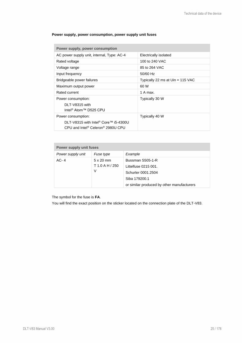
Power supply, power consumption, power supply unit fuses
Power supply, power consumption
AC power supply unit, internal, Type: AC-4 Electrically isolated
Rated voltage 100 to 240 VAC
Voltage range 85 to 264 VAC
Input frequency 50/60 Hz
Bridgeable power failures Typically 22 ms at Uin = 115 VAC
Maximum output power 60 W
Rated current 1 A max.
Power consumption:
DLT-V8315 with
Intel® Atom™ D525 CPU
Typically 30 W
Power consumption:
DLT-V8315 with Intel® Core™ i5-4300U
CPU and Intel® Celeron® 2980U CPU
Typically 40 W
Power supply unit fuses
Power supply unit Fuse type Example
AC- 4 5 x 20 mm
T 1.0 A H / 250
V
Bussman S505-1-R
Littelfuse 0215 001.
Schurter 0001.2504
Siba 179200.1
or similar produced by other manufacturers
The symbol for the fuse is FA.
You will find the exact position on the sticker located on the connection plate of the DLT-V83.
Technical data of the device
26 / 178 DLT-V83 Manual V3.01
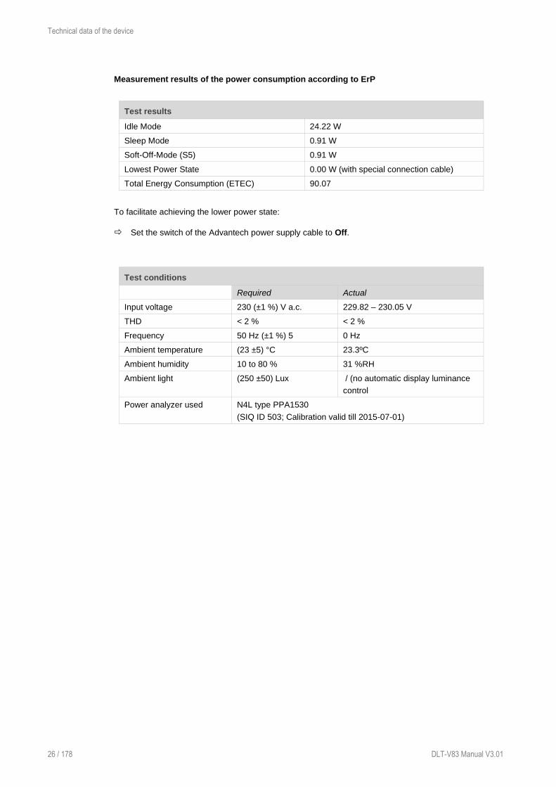
Measurement results of the power consumption according to ErP
Test results
Idle Mode 24.22 W
Sleep Mode 0.91 W
Soft-Off-Mode (S5) 0.91 W
Lowest Power State 0.00 W (with special connection cable)
Total Energy Consumption (ETEC) 90.07
To facilitate achieving the lower power state:
Set the switch of the Advantech power supply cable to Off.
Test conditions
Required Actual
Input voltage 230 (±1 %) V a.c. 229.82 – 230.05 V
THD < 2 % < 2 %
Frequency 50 Hz (±1 %) 5 0 Hz
Ambient temperature (23 ±5) °C 23.3ºC
Ambient humidity 10 to 80 % 31 %RH
Ambient light (250 ±50) Lux / (no automatic display luminance
control
Power analyzer used N4L type PPA1530
(SIQ ID 503; Calibration valid till 2015-07-01)

Technical data on radio modules
DLT-V83 Manual V3.00 27 / 178
6. Technical data on radio modules
NOTICE: Property damage
DLT-V83 may only be operated with the radio modules described in the following section.
6.1. Identification of the equipment variants
The DLT-V83 offers numerous radio equipment variants for WLAN, WWAN, GNSS and Bluetooth. To
identify the variant installed in your device, proceed as follows:
− Read off the FCCID on the device name plate/label and compare with the technical data on the
following pages.
− Open the Device Manager to determine the name of the radio card, for example
The radio equipment variants for WLAN, WWAN, GNSS and Bluetooth are available as options and are
not included in the standard scope of delivery of the DLT-V83.
6.2. Radio cards
WARNING
Only the manufacturer and its authorized service centers may install/remove radio
cards.
Radio cards are located inside the devices and are not accessible from the outside. Only the
manufacturer and its authorized service centers may open the device and install/remove it.
6.2.1. Available radio cards for WLAN
SUMMIT/LAIRD SDC-PE15N
Card type WLAN PCIe Full-Mini Card
Technology WLAN IEEE 802.11 a/b/g/n
FCCID TWG-SDCPE15N
IC ID 6616A-SDCPE15N
Band 1: WLAN 2.4 GHz
Frequency range 2400 to 2485 MHz
Frequency band ETSI Europe 2.4 GHz to 2.483 GHz
Channels available 1 to 13
Supported standards WLAN IEEE 802.11 a/b/g/n
Maximum TX power: 100 mW / 20 dBm
Band 2: WLAN 5 GHz
Frequency range 5150 to 5875 MHz
Frequency band ETSI Europe 5.15 GHz to 5.35 GHz
5.47 GHz to 5.725 GHz
Channels available 36 to 165

Technical data on radio modules
28 / 178 DLT-V83 Manual V3.01
Supported standards WLAN IEEE 802.11 a/n
Maximum TX power 100 mW / 20 dBm
SPARKLAN WPEQ-261ACN(BT)
Card type WLAN PCIe Half-Mini Card
Technology WLAN IEEE802.11 a/b/g/n/ac
Bluetooth
(both supported via a single antenna)
FCCID RYK-261ACNBT
IC ID 6158A-261ACBT
Band 1: WLAN 2.4 GHz
Frequency range 2400 to 2485 MHz
Frequency band ETSI Europe 2.4 GHz to 2.483 GHz
Channels available 1 to 13
Supported standards WLAN IEEE802.11 a/b/g/n/ac
Bluetooth (both supported via a single antenna)
Maximum TX power 100 mW / 20 dBm
Band 2: WLAN 5 GHz
Frequency range 5150 to 5875 MHz
Frequency band ETSI Europe 5.15 GHz to 5.35 GHz
5.47 GHz to 5.725 GHz
Channels available 36 to 165
Supported standards WLAN IEEE802.11 a/b/g/n/ac
Maximum TX power 100 mW / 20 dBm

Technical data on radio modules
DLT-V83 Manual V3.00 29 / 178
6.2.2. Available Radio cards for WWAN
USA: SIERRA WIRELESS MC8090
Europe: SIERRA WIRELESS MC8092
Card type WWAN PCIe Full-Mini Card
Technology WWAN 3G
FCCID N7NSL8090
Band Frequencies Conducted Tx Power
Average Notes
GSM Bands
GSM 850 TX: 824 to 849 MHz +33 ± 2 dBm GMSK, connectorized (Class 4)
EGSM 900 TX: 880 to 915 MHz +33 ± 2 dBm GMSK, connectorized (Class 4)
DCS 1800 TX: 1710 to 1785 MHz +30 ± 2 dBm GMSK, connectorized (Class 1)
PCS 1900 TX: 1850 to 1910 MHz +30 ± 2 dBm GMSK, connectorized (Class 1)
USA: QUECTEL EC25A
Europe: QUECTEL EC25E
Card type WWAN PCIe Full-Mini Card
Technology WWAN 2G, 3G, 4G cellular bands and GNSS
FCCID FCC ID: XMR201605EC25A
(valid for the EC25-A variant)
Maximum transmitting power Class 3 (23dBm±2dB) for LTE FDD
Class 3 (23dBm±2dB) for LTE TDD
Class 3 (24dBm+1/-3dB) for TD-SCDMA
Class 3 (24dBm+1/-3dB) for WCDMA
Class E2 (27dBm±3dB) for EDGE 850/900MHz
Class E2 (26dBm+3/-4dB) for EDGE
1800/1900MHz
Class 4 (33dBm±2dB) for GSM 850/900MHz
Class 1 (30dBm±2dB) for GSM 1800/1900MHz

Technical data on radio modules
30 / 178 DLT-V83 Manual V3.01
6.3. Antennas
6.3.1. WLAN antenna diversity, low profile IEEE 802.11 a/b/g/n
Antenna module (visible with antenna cap open)
Fig. 6.1: WLAN antenna IEEE 802.11 a/b/g/n and antenna module (optional)
Technical data
Application WLAN IEEE 802.11 a/b/g/n Dual Band Diversity
WLAN frequency ranges Band 1: 2400 to 2485 MHz
Band 2: 5150 to 5875 MHz
Number of antennas 2
Available colors Red, gray, blue
Type Omnidirectional antenna
Antenna gain Max. 5 dBi (without loss through the cable)
Impedance 50 Ω
Polarization Vertical/horizontal
Maximum transmitting power 100 mW / 20 dBm
Compatible Radio card: SUMMIT/LAIRD SDC-PE15N
(see section 6.2.1 Available radio cards)

Technical data on radio modules
DLT-V83 Manual V3.00 31 / 178
6.3.2. WLAN antenna IEEE 802.11 a/b/g/n/ac
Antenna module (visible with antenna cap open)
Fig. 6.2: WLAN antenna IEEE 802.11 a/b/g/n/ac and antenna module (optional)
Technical data
Application WLAN a/b/g/n/ac Dual Band with MRC
Bluetooth (integrated via Radio card)
WLAN frequency range Band 1: 2400 to 2485 MHz
Band 2: 5150 to 5850 MHz
Bluetooth features See section 6.4.1 Bluetooth
Number of antennas 2
Available color Red
Type Omnidirectional antenna
Antenna gain Max. 4.44 dBi (without loss through the cable)
Impedance 50 Ω
Polarization Vertical/horizontal
Maximum transmitting power 100 mW / 20 dBm
Compatible Radio card: SPARKLAN WPEQ-261ACN(BT)
(see section 6.2.1 Available radio cards)

Technical data on radio modules
32 / 178 DLT-V83 Manual V3.01
6.3.3. WLAN, WWAN 3G
Fig. 6.3: WLAN, WWAN 3G antenna (optional)
Technical data
Application WLAN IEEE 802.11 a/b/g/n Dual Band Diversity
WWAN 3G
WLAN frequency range Band 1: 2400 to 2485 MHz
Band 2: 5150 to 5875 MHz
WWAN frequency range GSM900: 880 to 960 MHz
GSM1800: 1710 to 1880 MHz
GSM1900: 1850 to 1990 MHz
UMTS: 1920 to 2170 MHz
Number of antennas 4
Available colors Red, gray
Type Omnidirectional antenna
Antenna gain Max. 3 dBi (without loss through the cable)
Impedance 50 Ω
Polarization Vertical/horizontal
Maximum transmitting power WLAN: 100 mW / 20 dBm
WWAN: 250 mW / 24 dBm
Compatible Radio card: SUMMIT/LAIRD SDC-PE15N
(see section 6.2.1 Available radio cards)
Compatible WWAN Radio card: USA: SIERRA WIRELESS MC8090
Europe: SIERRA WIRELESS MC8092
(see section 6.2.2 Available Radio cards)

Technical data on radio modules
DLT-V83 Manual V3.00 33 / 178
6.3.4. WLAN, WWAN, LTE 4G antenna (Multiband)
Antenna module (visible with antenna cap open)
Fig. 6.4: DLT-V83 rear view with WLAN, WWAN, LTE 4G antenna (Multiband)
Technical data
Application WLAN IEEE 802.11 a/b/g/n/ac Dual Band with MRC
WWAN 4G
Bluetooth
WLAN frequency range Band 1: 2400 to 2485 MHz
Band 2: 5150 to 5875 MHz
WWAN frequency bands
with EC25-E
FDD LTE: B1/B3/B5/B7/B8/B20
TDD LTE: B38/B40/B41
WCDMA: B1/B5/B8
GSM: 900/1800
WWAN frequency bands
with EC25-A
FDD LTE: B2/B4/B12
WCDMA: B2/B4/B5
Bluetooth features See section 6.4.1 Bluetooth
Number of antennas 4
Available color Red
Type Omnidirectional antenna
Antenna gain WLAN: Max. 5.8 dBi
WWAN: Max. 3.5 dBi
Impedance 50 Ω
Polarization Vertical/horizontal
Maximum transmitting
power
WLAN: 100 mW / 20 dBm
WWAN:
Class 3 (23dBm±2dB) for LTE FDD
Class 3 (23dBm±2dB) for LTE TDD
Class 3 (24dBm+1/-3dB) for TD-SCDMA
Class 3 (24dBm+1/-3dB) for WCDMA
Class E2 (27dBm±3dB) for EDGE 850/900MHz
Class E2 (26dBm+3/-4dB) for EDGE
1800/1900MHz
Class 4 (33dBm±2dB) for GSM 850/900MHz
Class 1 (30dBm±2dB) for GSM 1800/1900MHz

Technical data on radio modules
34 / 178 DLT-V83 Manual V3.01
Compatible WLAN card: SPARKLAN WPEQ-261 ACN (BT)
(see section 6.2.1 Available radio cards))
Compatible WWAN card: USA: QUECTEL EC25A
Europe: QUECTEL EC25E
(see section 6.2.2 Available Radio cards)
6.3.5. External WLAN antenna IEEE 802.11 a/b/g/n
Fig. 6.5: External WLAN antenna (optional)
Technical data
Application WLAN IEEE 802.11 a/b/g/n Dual Band
Mounting location For detached mounting, e.g. on the roof of the forklift
WLAN frequency range Band 1: 2400 to 2485 MHz
Band 2: 5150 to 5875 MHz
Number of antennas 1
Type Omnidirectional antenna
Antenna gain Band 1: Max. 4 dBi (without loss through the cable)
Band 2: Max. 6.5 dBi (without loss through the cable)
Impedance 50 Ω
Polarization Vertical/horizontal
Dimensions Ø 86 x 43 mm (Ø 3.39” x 1.69”)
Weight 0.3 kg (0.66 lbs)
Connector labeling N-type or TNC N, Jack, female, bottom
RSMA plug for RSMA socket on the terminal
Scope of delivery 3 m antenna cable
Maximum transmitting power 100 mW / 20 dBm
Corresponding Radio cards: SUMMIT/LAIRD SDC-PE15N
SPARKLAN WPEQ-261 ACN (BT)
(see section 6.2.1 Available radio cards)
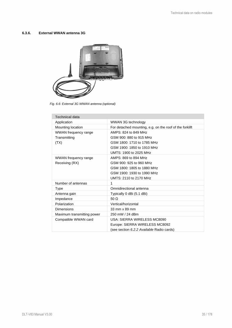
Technical data on radio modules
DLT-V83 Manual V3.00 35 / 178
6.3.6. External WWAN antenna 3G
Fig. 6.6: External 3G WWAN antenna (optional)
Technical data
Application WWAN 3G technology
Mounting location For detached mounting, e.g. on the roof of the forklift
WWAN frequency range
Transmitting
(TX)
AMPS: 824 to 849 MHz
GSM 900: 880 to 915 MHz
GSM 1800: 1710 to 1785 MHz
GSM 1900: 1850 to 1910 MHz
UMTS: 1900 to 2025 MHz
WWAN frequency range
Receiving (RX)
AMPS: 869 to 894 MHz
GSM 900: 925 to 960 MHz
GSM 1800: 1805 to 1880 MHz
GSM 1900: 1930 to 1990 MHz
UMTS: 2110 to 2170 MHz
Number of antennas 1
Type Omnidirectional antenna
Antenna gain Typically 0 dBi (5.1 dBi)
Impedance 50 Ω
Polarization Vertical/horizontal
Dimensions 33 mm x 89 mm
Maximum transmitting power 250 mW / 24 dBm
Compatible WWAN card USA: SIERRA WIRELESS MC8090
Europe: SIERRA WIRELESS MC8092
(see section 6.2.2 Available Radio cards)
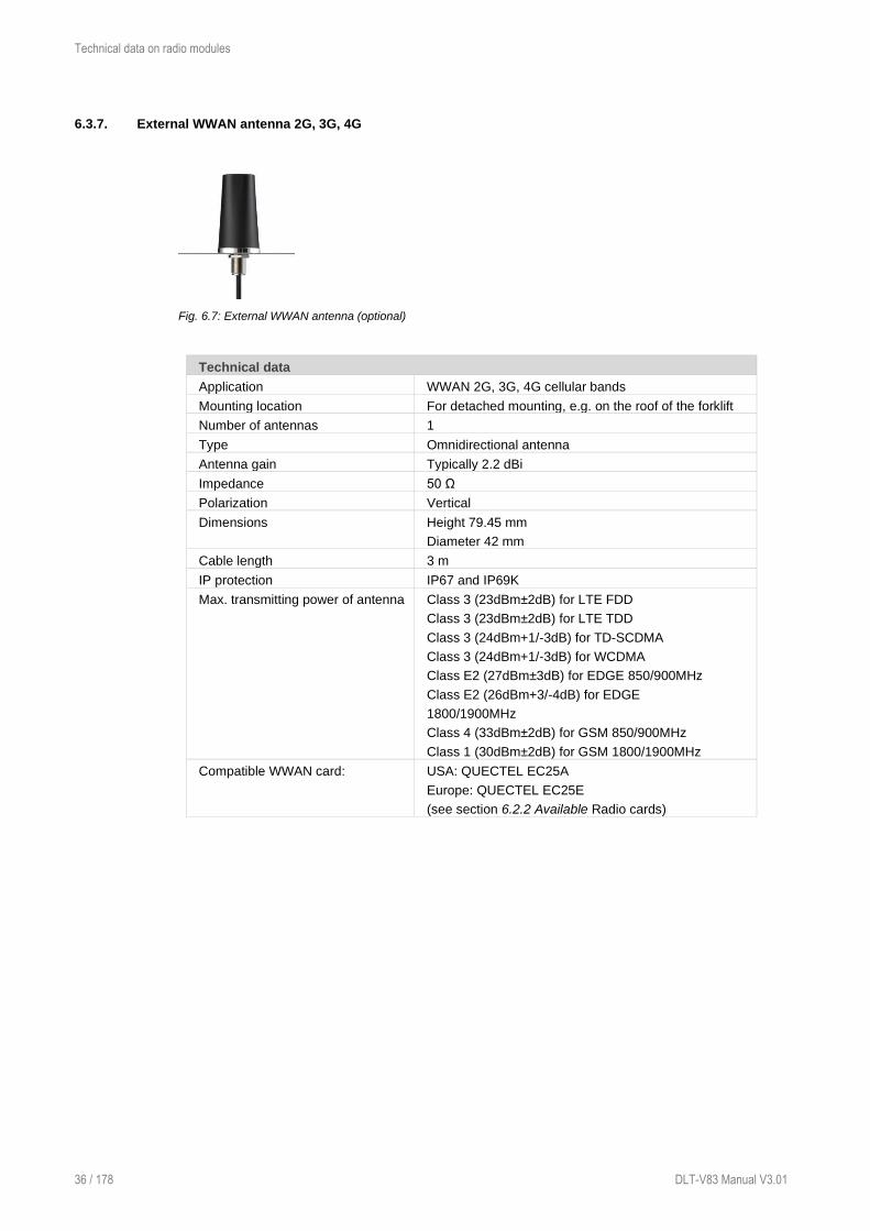
Technical data on radio modules
36 / 178 DLT-V83 Manual V3.01
6.3.7. External WWAN antenna 2G, 3G, 4G
Fig. 6.7: External WWAN antenna (optional)
Technical data
Application WWAN 2G, 3G, 4G cellular bands
Mounting location For detached mounting, e.g. on the roof of the forklift
Number of antennas 1
Type Omnidirectional antenna
Antenna gain Typically 2.2 dBi
Impedance 50 Ω
Polarization Vertical
Dimensions Height 79.45 mm
Diameter 42 mm
Cable length 3 m
IP protection IP67 and IP69K
Max. transmitting power of antenna Class 3 (23dBm±2dB) for LTE FDD
Class 3 (23dBm±2dB) for LTE TDD
Class 3 (24dBm+1/-3dB) for TD-SCDMA
Class 3 (24dBm+1/-3dB) for WCDMA
Class E2 (27dBm±3dB) for EDGE 850/900MHz
Class E2 (26dBm+3/-4dB) for EDGE
1800/1900MHz
Class 4 (33dBm±2dB) for GSM 850/900MHz
Class 1 (30dBm±2dB) for GSM 1800/1900MHz
Compatible WWAN card: USA: QUECTEL EC25A
Europe: QUECTEL EC25E
(see section 6.2.2 Available Radio cards)

Technical data on radio modules
DLT-V83 Manual V3.00 37 / 178
6.4. Bluetooth (optional)
The DLT-V83 offers the following Bluetooth options:
6.4.1. Bluetooth integrated: WLAN card SPARKLAN WPEQ-261ACN (BT)
Requirement: Use of the WLAN card SPARKLAN WPEQ-261ACN (BT)
− Bluetooth Type 5.0
− Standards: V5.0, V4.2 +HS, V4.0 LE, V3.0+HS, V2.1+EDR
− Transmission rate: 1 Mbps, 2 Mbps, up to 3 Mbps
6.4.2. Micro Bluetooth adapter (USB stick)
The optional micro Bluetooth adapter permits the WLAN connection between the DLT-V83 and
Bluetooth devices.
If the Bluetooth option was ordered, this adapter is already integrated into the Service USB interface
under the antenna.
Technical data
Type USB adapter Bluetooth 2.0
Transmission rate EDR transmission rate up to 2.1 Mbit/s
General range 10 m
Class Class 2 Micro Size
Compatibility Compatible with USB 2.0/1.1
Supports A2DP stereo transmission
Compatible operating system Windows 7
Windows 8
Windows 10
Linux optional
Maximum transmitting power 2.5 mW

Technical data on radio modules
38 / 178 DLT-V83 Manual V3.01
6.5. GPS receiver external (optional)
With the optional GPS receiver the DLT-V83 can be used for GPS navigation.
The GPS receiver has an integrated antenna for position data of the Global Positioning System (GPS)
and communicates with the DLT-V83 via USB interface.
We recommend using only a GPS receiver approved by Advantech.
Fig. 6.8: External GPS receiver (optional)
Installation
The installation CD supplied with the GPS receiver includes installation files and a multi-lingual manual.
Please read the additional information in the manual about the GPS receiver.
Fig. 6.9: Ext. GPS receiver, display example during installation

Interfaces, connectors
DLT-V83 Manual V3.00 39 / 178
7. Interfaces, connectors
7.1. Integrated
7.1.1. LCD interface
VGA Controller
Intel® Core™ i5-4300U Intel® Celeron® 2980U Intel® Atom™ D525
Intel® HD graphics 4400
Max. dynamic graphic frequency
1.1 GHz
Graphic Memory Intel® DVMT 5.0
Up to 1024 MB video memory
supported
3D/HW acceleration
DX 11.2/12, OGL 4.3,
OCL 1.2 support
Intel® Quick-Sync-Video
Up to 24 bit color depth, depending
on which LCD is used
Intel® HD graphics
Max. dynamic graphic
frequency 1.0 GHz
Graphic Memory Intel®
DVMT 5.0
Up to 1024 MB video memory
supported
3D/HW acceleration
DX 11.2/12, OGL 4.3,
OCL 1.2 support
No Intel® Quick-Sync-Video
Up to 24 bit color depth,
depending on which LCD is
used
Intel® Gen 3.5 DX9,
MPEG2 hardware
decoder
Shared Memory
architecture
Up to 24 bit color depth,
depending on which
LCD is used
7.1.2. Touch interface
Resistive touch controller 12-bit touch controller for touchscreens with USB interface
PCT touch controller 10": X21-Y28 channel PCT controller with USB interface and
Advantech-specific firmware;
12" and 15": X52-Y40 channel PCT controller with USB interface
and Advantech-specific firmware

Interfaces, connectors
40 / 178 DLT-V83 Manual V3.01
7.2. External
7.2.1. Serial interfaces
COM1 Max. 115,200 Baud (16550A compatible, 16 byte FIFO), supports EIA-
232-E on external 9-pin D-Sub connection
ESD Level 4 protected (according to EN 61000-4-2)
Optional: COM1 with 5 V or 12 V
COM2 Max. 115,200 Baud (16550A compatible, 16 byte FIFO), supports EIA-
232-E on external 9-pin D-Sub connection
ESD level 4 protected (acc. to EN 61000-4-2)
Optional: COM2 as a galvanically isolated EIA-422/485
7.2.2. USB, Service-USB
USB connection,
for example for mouse,
keyboard, USB stick
3 x USB 2.0 Host
USB 2.0 HiSpeed
Fused at 0.5 A per channel
ESD Level 4 protected (according to EN 61000-4-2)
Service USB
e.g. for mouse, keyboard,
USB stick
1 x USB 2.0 Host, Service-connection under antenna cap
USB 2.0 HiSpeed
Fused at 0.5 A per channel
ESD level 4 protected (acc. to EN 61000-4-2)
7.2.3. Audio interface for handset
Audio handset-connection Microphone input
Audio out max. 2 W @ 8 Ohm
ESD Level 3 protected (according to EN 61000-4-2)
7.2.4. Network interface
CPU Intel® Core™ i5-4300U and Intel® Celeron® 2980U
Network controller Intel® i218LM Gigabit Ethernet 10/100/1000 MB/s
Network connection RJ45 connector
Integrated carrier
Two integrated status LEDs
Intel® Atom™ D525
Network controller Intel® 82567V Gigabit Ethernet 10/100/1000 MB/s
Network connection RJ45 connector
Integrated carrier
Two integrated status LEDs
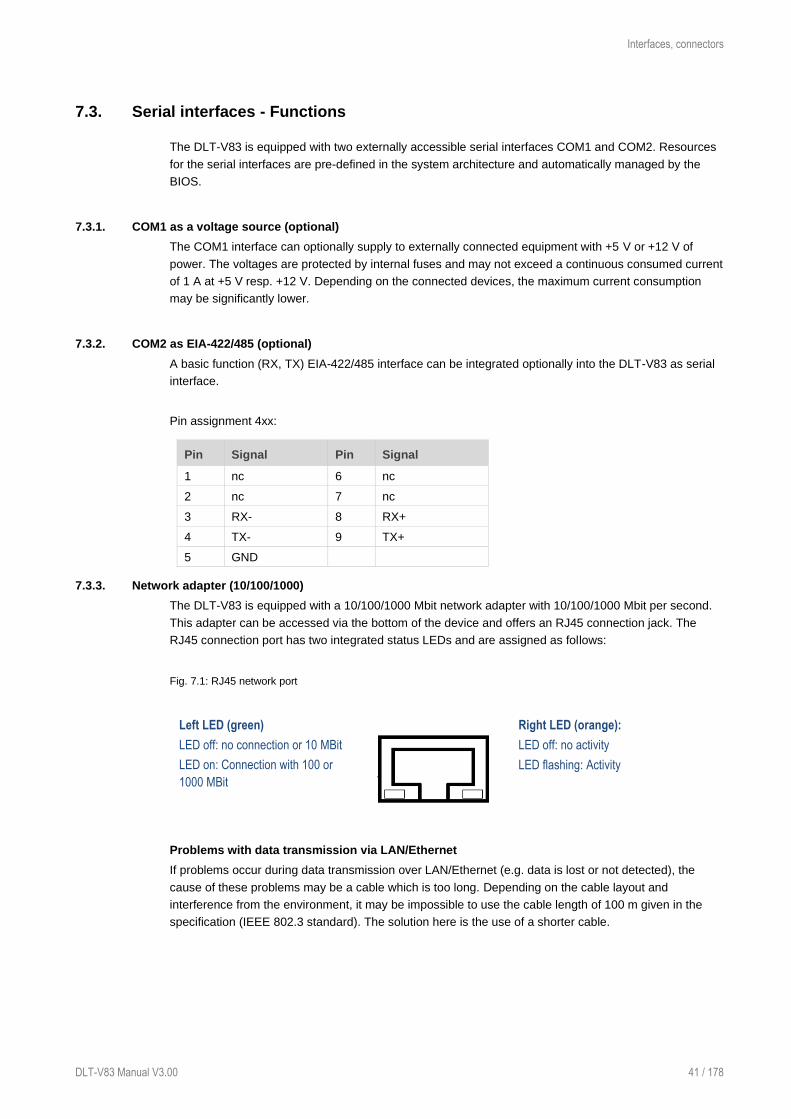
Interfaces, connectors
DLT-V83 Manual V3.00 41 / 178
7.3. Serial interfaces - Functions
The DLT-V83 is equipped with two externally accessible serial interfaces COM1 and COM2. Resources
for the serial interfaces are pre-defined in the system architecture and automatically managed by the
BIOS.
7.3.1. COM1 as a voltage source (optional)
The COM1 interface can optionally supply to externally connected equipment with +5 V or +12 V of
power. The voltages are protected by internal fuses and may not exceed a continuous consumed current
of 1 A at +5 V resp. +12 V. Depending on the connected devices, the maximum current consumption
may be significantly lower.
7.3.2. COM2 as EIA-422/485 (optional)
A basic function (RX, TX) EIA-422/485 interface can be integrated optionally into the DLT-V83 as serial
interface.
Pin assignment 4xx:
Pin Signal Pin Signal
1 nc 6 nc
2 nc 7 nc
3 RX- 8 RX+
4 TX- 9 TX+
5 GND
7.3.3. Network adapter (10/100/1000)
The DLT-V83 is equipped with a 10/100/1000 Mbit network adapter with 10/100/1000 Mbit per second.
This adapter can be accessed via the bottom of the device and offers an RJ45 connection jack. The
RJ45 connection port has two integrated status LEDs and are assigned as follows:
Fig. 7.1: RJ45 network port
Left LED (green)
Right LED (orange):
LED off: no connection or 10 MBit LED off: no activity
LED on: Connection with 100 or
1000 MBit
LED flashing: Activity
Problems with data transmission via LAN/Ethernet
If problems occur during data transmission over LAN/Ethernet (e.g. data is lost or not detected), the
cause of these problems may be a cable which is too long. Depending on the cable layout and
interference from the environment, it may be impossible to use the cable length of 100 m given in the
specification (IEEE 802.3 standard). The solution here is the use of a shorter cable.

Interfaces, connectors
42 / 178 DLT-V83 Manual V3.01
7.3.4. CAN, digital I/O and second Ethernet interface (optional)
CAN, Digital In/Out and LAN Ethernet is available as an optional expansion interface package. At the
lower right in the illustration is the position of these interfaces on the DLT-V83 connector panel:
Fig. 7.2: CAN, Digital In/Out and second Ethernet interface
CAN interface
The CAN interface is galvanically separated from the overall system.
A 120 Ω terminating resistor is mounted on the pcb.
A matching driver is integrated in the operating system. An API description is available upon request.
Contact your Advantech sales representative if necessary.
Fig. 7.3: Pin assignment of CAN interface
Matching connectors (examples):
Manufacturer Series Order no. Description
Weidmüller BL 3.5/180F 1606650000 BL 3.50/03/180F SN OR BX
Weidmüller BL 3.5/180F 1615790000 BL 3.50/03/180F SN BK BX
Weidmüller BL 3.5/180F 1740721001 BL 3.50/03/180F SN OR BX PRT
Weidmüller BL 3.5/180 1597370000 BL 3.50/03/180 SN OR BX
Weidmüller BL 3.5/90 1638790000 BL 3.50/03/90 SN BK BX

Interfaces, connectors
DLT-V83 Manual V3.00 43 / 178
Digital I/O interface
The Digital I/O interface is galvanically separated from the overall system. A matching driver is
integrated in the operating system. An API description as well as sample application are available upon
request. Contact your Advantech sales representative if necessary.
Pin assignment:
Pin Signal
1 DI1+ Provides 12 VDC / max. 8 mA
2 DI1- Input DI1 -> selectable up to max. 12 VDC / 100 Hz filter integrated
3 DI2+ Provides 12 VDC / max. 8 mA
4 DI2- Input DI1 -> selectable up to max. 12 VDC / 100 Hz filter integrated
5 DIO_GND GND Potential for Digital I/O application
6 DO1 Output 1: supplies 12 VDC / 20 mA
7 DO2 Output 1: supplies 12 VDC / 20 mA
8 DO3 Output 1: supplies 12 VDC / 20 mA
Fig. 7.4: Digital I/O interface pin position
Matching connectors (examples):
Manufacturer Series Order no. Description
Weidmüller B2L 3.50F 1748180000 B2L 3.50/08/180F SN BK BX
Weidmüller B2L 3.50 1847530000 B2L 3.50/08/180 SN OR BX PRT
Weidmüller B2L 3.50 1024270000 B2L 3.50/08/180 SN BK BX PRT

Interfaces, connectors
44 / 178 DLT-V83 Manual V3.01
Network adapter 2, Ethernet (10/100/1000)
The DLT-V83 is equipped with an optional network adapter with 10/100/1000 Mbit per second. This
adapter is accessible via the underside of the device and features a RJ45 socket.
The RJ45 connection port has two integrated status LEDs and are assigned as follows:
Fig. 7.5: Optional RJ45 network socket of the DLT-V83
Left LED (green)
Right LED (orange):
LED off: no connection
or 10/100 MBit
LED on: Connection with 1000 MBit
LED flashing: Activity 1000 MBit
LED off: no connection
or 1000 MBit
LED on: Connection with 10 or
100 MBit
LED flashing: Activity 10/100 MBit
7.3.5. Serial interface barcode scanners
The serial wedge is integrated as standard in WES 2009 and Windows XP Professional only.
Please note that you have to configure the scanner correctly to EIA-232-E and the above set BAUD rate
following the scanner manufacturer’s guidelines. Otherwise the software wedge will not function
properly.
To activate the integrated scanner software wedge:
Open the Start menu and navigate to Settings | Control Panel | Accessibility.
Select the General tab.
Select Support accessibility option.
Click Settings.
Configure the desired COM1 interface and BAUD rate.
Confirm the change with OK.
Click OK again to apply the changes.
7.3.6. Tips & tricks
Note that according to the EIA-232-E specification, the maximum cable length is 15 m at 19,200 bps.
However, according to EIA-422-A for use of a twisted pair line and correct termination 1200 m at up to
100 kbps is possible. For a data rate of 1 Mbps and a high-quality connection cable, approx. 400 m
cable lengths are still possible. Frequent causes of malfunctions for EIA-232-E connections are the
formation of ground loops. If both end devices establish a ground connection via EIA-232-E but do not
share the same ground potential in their power supply circuits, then compensation currents may result;
this is particularly noticeable with long cables.
These compensation currents, which are also present at the ground point of the EIA-232-E connection,
may significantly degrade signal quality and effectively stop the data flow. In challenging environments,
electrically-isolated connections (via the RS-422/485 option) or external converter from EIA-232-E
according to EIA-422/485 are strongly recommended.

Interfaces, connectors
DLT-V83 Manual V3.00 45 / 178
7.4. Connections under the cable cover
7.4.1. DC devices: connections, expansion interfaces
The symbol for the fuse is FA.
Fig. 7.6: DC device external connections with optional expansion interfaces
Pin assignment (standard)
Power supply 12/24/48 VDC nominal
UPS (optional) Uninterruptible power supply (UPS)
2 x SMA (optional) WWAN/GPS
Audio MIC PWR out Voice Kit
COM1, COM2 Serial interfaces
2 x RSMA (optional) Remote WLAN antenna(s)
RJ45 LAN Ethernet 10/100/1000 MBit/s
USB2, USB1, USB0 USB 2.0 interfaces (HI-SPEED™), bootable
Expansion interfaces package 1 (optional)
D I/O Digital In/Out
RJ45 LAN Ethernet 10/100/1000 MBit/s
Expansion interfaces package 2 (optional)
CAN CAN interface
D I/O Digital In/Out
RJ45 LAN Ethernet 10/100/1000 MBit/s

Interfaces, connectors
46 / 178 DLT-V83 Manual V3.01
7.4.2. AC devices (DLT-V8315 only): connections, expansion interfaces
Fig. 7.7: AC device external connections with optional expansion interfaces
Pin assignment (standard)
Power supply
DLT-V8315
100 to 240 VAC
Audio MIC PWR out Voice kit
COM1, COM2 Serial interfaces
2 x RSMA (optional) Remote WLAN antenna(s)
RJ45 LAN Ethernet 10/100/1000 Mbps
USB2, USB1, USB0 USB 2.0 interfaces (HI-SPEED™), bootable
Expansion interfaces package 1 (optional)
D I/O Digital I/O
RJ45 LAN Ethernet 10/100/1000 Mbps
Expansion interfaces package 2 (optional)
CAN CAN interface
D I/O Digital I/O
RJ45 LAN Ethernet 10/100/1000 Mbps

Interfaces, connectors
DLT-V83 Manual V3.00 47 / 178
7.5. Connections underneath the antenna/protective cap
The DLT-V83 offers the following interfaces underneath the antenna or underneath the protective cap
(depending on the device version ordered):
− Service USB slot
− CFast slot
− Mini SIM card slot
NOTICE: Property damage
These interfaces may only be used by qualified expert personnel and only for the duration of
service works (e.g. software updates, card replacement).
Example for antenna on the device: Example for protective cap on the device
(if no antenna is present):
Fig. 7.8: Example of antenna, type 4 in 1 Fig. 7.9: Protective cap examples
7.5.1. Information on service USB, CFast and Mini SIM card slot
Service
USB slot
Plug connector with increased pull-out force (to fulfill the specific shock and
vibration requirements of the DLT-V83).
Exercise special care when removing and plugging in USB sticks.
CFast slot Insert CFast card precisely into the slot guide rails. Otherwise, there is a risk of
the CFast card dropping into the device when inserting it.
Mini SIM
card slot for
WWAN
Insert/remove mini SIM card
− Press the yellow unlock button next to the mini SIM card slot.
The card opens and extrudes slightly from the device.
− Pull the card tray completely out of the device.
The mini SIM card can now be inserted or removed.
− Carefully push the card tray in again.
NOTICE: Push in the card tray exactly at the location provided. Otherwise,
there is a risk of the tray and mini SIM card dropping into the device when
pushing in the tray.

Open/close antenna (or protective cap)
48 / 178 DLT-V83 Manual V3.01
8. Open/close antenna (or protective cap)
The DLT-V83 is normally equipped with an antenna for radio operation. Devices without radio operation
have no antenna and instead have what is known as a "protective cap".
The following interfaces are located underneath the antenna or protective cap:
− Service USB
− CFast
− Mini SIM card slot
8.1. Avoid Property damage
NOTICE: Property damage
Protective caps or antennas:
− are only permitted to be removed for servicing purposes, e.g. to install software updates.
− are only permitted to be removed by qualified expert personnel.
No objects or liquids are permitted to enter the opened DLT-V83.
The device is only permitted to be operated again once the protective cap or antenna is
properly sealed again; only then is the protection class guaranteed.
When opening and closing, proceed as described in the sections below.
8.1.1. Disconnecting from the electric power source
− Switch off the DLT-V83 before the protective cap or antenna is removed.
− Only insert/remove the mini SIM card, CFast card and USB stick when the device has been
completely de-energized.
Please note: For DLT-V83 devices with integrated UPS the device may be in operation despite the
disconnecting device being actuated, since it is supplied with power by the UPS. Likewise, the
peripherals that are supplied by the device are also not currentless as long as the DLT-V83 is being
provided with power by the UPS.
8.1.2. Tools required
To open the following component: Use this tool:
Protective cap − 3mm Allen wrench
4 in 1 multi-band antenna
Low profile WLAN antenna (low)
− Torx screwdriver, Tx20
− Allen key (size 7)
All high profile antenna (high) − Allen key (size 3)

Open/close antenna (or protective cap)
DLT-V83 Manual V3.00 49 / 178
8.2. Open/close protective cap
Open protective cap:
Unfasten both screws on the protective cap
using a 3mm Allen wrench.
Remove the protective cap from the device.
The interfaces are now accessible.
Close protective cap:
Place the protective cap back onto the DLT-V83.
Tighten both screws (1 Nm torque).
8.3. Open/close antenna
8.3.1. WLAN antenna IEEE 802.11 a/b/g/n
Open antenna:
NOTICE: Property damage
Remove the antenna extremely carefully from the device, as it is secured using thin connection
cables onto the Radio card(s) in the interior of the device.
The connection cables can be detached from the antenna and the radio card, meaning WLAN
operation is no longer guaranteed.
Unfasten both screws on the antenna.
Tool: Torx screwdriver, Tx20
Lift the antenna carefully to avoid pulling on the connection cables (raise by a maximum of 2 to 3
cm).
Fig. 8.1: WLAN antenna unscrewed
Do not pull the connection cables too
far out of the device, and do not allow
them to get caught or severed.
Close antenna:
Place the antenna back onto the DLT-V83.
Take care not to pinch the connection cables when doing this.
The antenna sealing must not be damaged; it must be seated correctly in the groove.
Tighten the two screws of the antenna again (1 Nm torque).

Open/close antenna (or protective cap)
50 / 178 DLT-V83 Manual V3.01
8.3.2. WLAN antenna IEEE 802.11 a/b/g/n/ac
Open antenna:
Fig. 8.2: Open WLAN antenna IEEE 802.11 a/b/g/n/ac
Unfasten both screws on the
antenna. Tool: Allen key (size 3)
Remove the antenna from the device.
Fig. 8.3: WLAN antenna IEEE 802.11 a/b/g/n/ac opened
Service USB, CFast and mini SIM card
slot are now accessible.
For details, see section 7.5.1 Information
on service USB, CFast and Mini SIM card
slot.
Close antenna:
Place the antenna back onto the DLT-V83.
Tighten both screws (1 Nm torque).

Open/close antenna (or protective cap)
DLT-V83 Manual V3.00 51 / 178
8.3.3. WLAN, WWAN 3G antenna
Open antenna:
Fig. 8.4: WLAN, WWAN 3G antenna
Unfasten both screws on the
antenna. Tool: Allen key (size 3)
Remove the antenna from the device.
Fig. 8.5: WLAN, WWAN 3G antenna opened
Service USB, CFast and mini SIM card
slot are now accessible.
For details, see section 7.5.1 Information
on service USB, CFast and Mini SIM card
slot.
Close antenna:
Place the antenna back onto the DLT-V83.
Tighten both screws (1 Nm torque).

Open/close antenna (or protective cap)
52 / 178 DLT-V83 Manual V3.01
8.3.4. WLAN, WWAN antenna (multi-band) LTE 4G
Open antenna:
Unfasten both screws on the
antenna cap.
Tool: Torx screwdriver, Tx20
Remove the antenna from the
device.
Fig. 8.6: Open WLAN, WWAN antenna
The antenna module is located underneath the antenna cap:
NOTICE: Property damage
Remove the antenna module extremely carefully from the device, as it is secured using thin
connection cables onto the Radio card(s) in the interior of the device.
The connection cables can be detached from the antenna module and the radio card, meaning
WLAN operation is no longer guaranteed.
Fig. 8.7: Open WLAN / WWAN antenna
Unfasten both bolts on the antenna
module.
Tool: Nut driver.
Notice: Property damage
Raise the antenna module
exceptionally carefully (connection
cables!)
Fig. 8.8: WLAN, WWAN antenna opened
Service USB, CFast and mini SIM card
slot are now accessible.
For details, see section 7.5.1 Information
on service USB, CFast and Mini SIM
card slot.

Open/close antenna (or protective cap)
DLT-V83 Manual V3.00 53 / 178
Fasten antenna module and antenna cap:
Place the antenna module back onto the DLT-V83.
Take care not to pinch or damage the connection cables when doing this.
Tighten the two bolts again (1 Nm torque).
Place the antenna cap back onto the DLT-V83.
Tighten the two screws of the antenna cap again (1 Nm torque).

Operating the device
54 / 178 DLT-V83 Manual V3.01
9. Operating the device
9.1. Safety notes for normal operation, control
WARNING
Personal injury, Property damage and downtimes due to improper operation.
Operators of the DLT-V83 must be trained in the handling of the device.
Users of DLT-V83 with integrated UPS must also be trained in the proper handling of battery
packs.
Risk of accident! Personal injury and Property damage caused by using the terminal
and driving at the same time.
Do not operate the DLT-V83 terminal while driving.
Risk of injury and Property damage due to improper deployment location (refueling
stations, etc.)
Observe the intended use of the DLT-V83, e.g. not in potentially explosive areas, not in
life-supporting facilities.
Turn off the DLT-V83 when you are near gas stations, fuel depots, chemical plants or
places where blasting operations take place.
Ensure that the deployment location of the DLT-V83 complies with the permissible
environmental conditions.
Personal injury from battery packs: Short-circuit, fire, chemical burns, toxic substances.
The integrated UPS battery packs in the cable cover of the DLT-V83 can ignite if handled
improperly (risk of fire), cause chemical burns or release toxic substances.
Handle the cable cover carefully.
Do not allow water or other liquids to come into contact with the device (exercise particular
caution with corrosive liquids).
Ensure that no liquids or foreign bodies get into the cable cover.
Provide sufficient ventilation.
Do not allow the device to come into contact with fire or operate it close to sources of heat
or fire, open flame or heaters.
Observe the specific IP protection class.
Only use the DLT-V83 within the permitted temperature and humidity range.
Do not subject it to strong impacts and vibrations that exceed what is specified by the
class 5M3/5M2 (DIN EN 60721-3-5).

Operating the device
DLT-V83 Manual V3.00 55 / 178
WARNING
Electric shock due to incomplete switching off of the DLT-V83 with integrated UPS.
Because of the battery packs, the integrated UPS may still carry current even if the DLT-V83
itself is switched off.
Reason: If the DLT-V83 has been configured to also start without <Power> button and ignition
in the "DLoG Config" program, this setting will need to be changed first.
Otherwise, the DLT-V83 will restart after a short pause as long as there is available battery
capacity.
To completely switch off the device:
Shut down the DLT-V83 via the operating system function.
Disconnect from the power supply.
Open the cable cover.
Unplug the UPS battery.
Vehicle EMERGENCY-OFF switch does not switch off the DLT-V83 with integrated UPS.
If a DLT-V83 with integrated UPS is installed in a vehicle, the EMERGENCY-OFF switch of the
vehicle has no effect on the DLT-V83.
This also applies to the peripherals supplied by the device.
NOTICE: Property damage
Overvoltage on the DLT-V83 when charging the vehicle battery.
While the vehicle battery is charging:
− The DLT-V83 must be disconnected from the vehicle battery.
− Or it must be ensured that the maximum permitted input voltage of the DLT-V83 is not
exceeded.
Charging the integrated UPS correctly.
Do not connect damaged cable covers with battery packs to the DLT-V83; do not charge.
Battery packs become warm while charging; this is normal. However, if they become
excessively hot, immediately disconnect the DLT-V83 from the power source.
Do not continue to use the DLT-V83 if you notice an unusual level of heat or an unusual
smell during charging.
Provide for sufficient ventilation of the DLT-V83 when charging the battery pack.
Parking vehicles with DLT-V83 devices with the "Screen-Defroster and integrated UPS"
equipment combination.
Do not park or store vehicles on which DLT-V83 devices with a Screen-Defroster and an
integrated UPS are installed in areas with ambient temperatures below 0°C.
If vehicles on which DLT-V83 devices with a Screen-Defroster and an integrated UPS are
installed are parked or stored for a significant length of time, disconnect the DLT-V83 from
the vehicle battery.

Operating the device
56 / 178 DLT-V83 Manual V3.01
9.2. Switching the DLT-V83 on/off
Switch the DLT-V83 on and off as follows, depending on the configuration:
Using the <Power> button. Press and hold the <Power> button for 2 seconds.
By applying the supply voltage.
Through the ignition signal of the vehicle.
Fig. 9.1: <Power> button
Time between switching off and on: 10 seconds
After the DLT-V83 has been shut down and switched off, it takes 10 seconds until the device will react to
a switch-on signal (<Power> button / ignition).
9.3. Operating the touchscreen
Depending on the device model, the DLT-V83 is equipped with a resistive touchscreen or a projected-
capacitive touchscreen with continuous glass front (abbreviated PCT).
TIP: Protective film for resistive touchscreens
Optional protective film is available for the resistive touchscreens.
Details in section 16.12 Protective film for touchscreen (optional).

Operating the device
DLT-V83 Manual V3.00 57 / 178
9.3.1. Prevent damage to the touchscreen
Information valid for all touchscreen types, resistive and PCT.
Keep the touchscreen clean.
To not touch the touchscreen with pointed, sharp, rough or hard objects, e.g. ball point pens, writing
implements, tools of any kind (e.g. screwdrivers).
Prevent any kind of adhesive applied on the surface.
Ensure that the screen surface is not influenced by high voltages or static electricity.
Do not use excessive force when touching touchscreens, do not hit or press hard.
Do not put the device down with the touchscreen facing down, if necessary, place a clean cloth
underneath.
9.3.2. Operating the resistive touchscreen
Operate the resistive touchscreen with:
− Clean, dry fingers.
− Clean, dry, soft gloves.
− Suitable touch stylus (plastic or wood, rounded tip).
9.3.3. Operating the PCT touchscreen
Operate the PCT touchscreen with:
− Clean, dry fingers.
− Clean, dry, thin gloves.
− Suitable touch stylus with capacitive (electrically conductive) tip.
NOTICE: Property damage
Water on the PCT touchscreen can be interpreted as a "touch" and lead to malfunctions.
Multi-touch capability
Depending on the installed operating system type, the PCT touchscreen of the DLT-V83 is multi-touch
capable. This means it can detect two touches simultaneously.

Operating the device
58 / 178 DLT-V83 Manual V3.01
9.4. DLT-V83 front keys with resistive touchscreen
9.4.1. Overview of the operating elements on the device front
Fig. 9.2: Example: DLT-V8312 version with 26 front keys
Front keys:
- Turn on/off
- Display brighter
- Display darker
- Backlighting
on/off
- Touch on, off
Front keys:
- Arrow keys
- Pg Up, Pg Dn
- Home
- End
- Special keys
S1, S2
- Esc
- Enter
Front keys:
Shift, function keys F1 to F12
Numbers 0 bis 9, point, backspace
LEDs:
- Temperature
- Flash drive
- Supply voltage

Operating the device
DLT-V83 Manual V3.00 59 / 178
9.4.2. Device with 26 front keys
Left on the device:
Key Explanation
<Power> button, switch device on/off
Manual brightness control: Display brighter
Manual brightness control: Display darker
Switch the backlight on/off
Note: The DLT-V83 will continue to react to keyboard, mouse and
touchscreen inputs even if the backlight is switched off. This means that
entries can still be made even when the screen display is not visible.
Touchscreen activate/deactivate
LED on (orange): Touchscreen deactivated
LED off: Touchscreen activated
<Shift> key; if the LED is illuminated, it indicates that the <Shift> is
activated
LED Explanation
LED (red): Indicates a device temperature outside the normal range.
LED (green): Indicates access to the flash drive.
LED (green): Display of available internal supply voltage.

Operating the device
60 / 178 DLT-V83 Manual V3.01
Right on the device:
Key Explanation
Page Up / Line Up (switch with <Shift> key)
Page Down / Line Down (switch with <Shift> key)
Home / Backwards (switch with <Shift> key)
End / Forwards (switch with <Shift> key)
Special keys <S1> and <S2>
These keys are configured with the "DLoG Config" program;
the associated manual is available on our websites.
<Esc> key
<Enter> key
Below on the device:
Key Explanation
…
Function keys and numbers 0 to 9, backspace
<Shift> pressed: Key function marked in grey is active
<Shift> not pressed: Key function marked in white is active.
The function keys are configured with the "DLoG Config" program, the
associated manual is available on our websites.

Operating the device
DLT-V83 Manual V3.00 61 / 178
9.4.3. Device with 5 front keys
Key Explanation
<Power> button, switch device on/off
Manual brightness control: Display brighter
Manual brightness control: Display darker
Backlight switch on/off
Note: The DLT-V83 will continue to react to keyboard, mouse and
touchscreen inputs even if the backlight is switched off.
Touchscreen activate/deactivate
LED on (orange): Touchscreen deactivated
LED off: Touchscreen activated
LED Explanation
LED (red): Indicates a device temperature outside the normal range
LED (green): Indicates access to the flash drive
LED (green): Display of available internal supply voltage

Operating the device
62 / 178 DLT-V83 Manual V3.01
9.4.4. Operating states
Status of LEDs DLT-V83 Status
Supply voltage
(green)
Temperature
(red)
OFF OFF Initial state, idle time – waiting for a new
ignition signal or for the <Power> key after
switch off; no voltage supply.
OFF FLASHING Temperature sensor malfunctioning.
FLASHING OFF DLT-V83 is in standby mode (S3).
OFF ON Computer will only start if the temperature in
the device is in the range between -30 and
+62 °C again.
ON OFF Computer start-up/normal operational
state/shutdown delay time.
ON ON Temperature < -30 or > +70 °C.
ON FLASHING Temperature sensor malfunctioning.

Operating the device
DLT-V83 Manual V3.00 63 / 178
9.5. DLT-V83 front keys with PCT touchscreen
9.5.1. Overview of the operating elements on the front side
Fig. 9.3: Example: Operating elements front side DLT-V8310 with PCT touchscreen
9.5.2. Function of the front keys
The keys are backlit in blue when the device is switched on.
When the key is pressed, the lighting switches briefly to white.
Keys and LED, left on the device:
Key Explanation
<Power> button, switch device on/off:
To do this, press and hold the button for 2 seconds
After the device has been switched off, it can only be switched on
again after 10 seconds.
Manual brightness control: Display brighter
Manual brightness control: Display darker
Front keys:
- Turn on/off
- Display brighter
- Display darker
- Backlighting on/off
Front keys:
- Special keys
- Shift

Operating the device
64 / 178 DLT-V83 Manual V3.01
Switch the backlight on/off
NOTE: The DLT-V83 will continue to react to keyboard, mouse and
touchscreen inputs even if the backlight is switched off.
The key glows white when the backlight is switched off
The backlight can also be switched on using the "Display brighter"
key.
LED Explanation
Access to storage medium (backlit green when active).
Key on the right of the device:
Key Explanation
Special keys <S1> to <S8>
These keys are configured with the "DLoG Config" program; the
associated manual is available on our websites.
Shift key
<Shift> is activated when the key lights up white.
This allows access to the functions <S5> to <S8>.
9.5.3. Operating states
<Power>
key Color Explanation
White
When the <Power> button is pressed briefly, it lights up
white.
To start the device, the key must be held pressed for at
least 2 seconds.
Blue Once the device boots, all keys light up blue until the
device is switched off again.
Red
Indicates a temperature in the device that is below or
above the normal range.
Computer will only start if the temperature in the device is
in the range between -30 and +62 °C again.
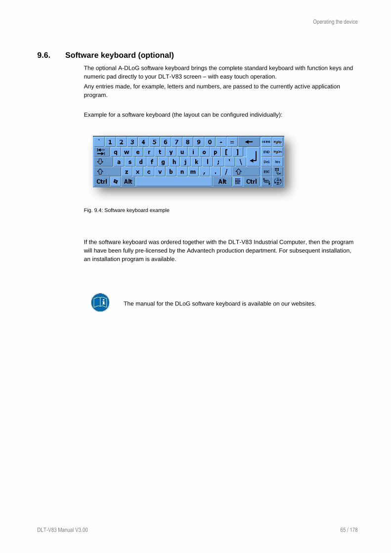
Operating the device
DLT-V83 Manual V3.00 65 / 178
9.6. Software keyboard (optional)
The optional A-DLoG software keyboard brings the complete standard keyboard with function keys and
numeric pad directly to your DLT-V83 screen – with easy touch operation.
Any entries made, for example, letters and numbers, are passed to the currently active application
program.
Example for a software keyboard (the layout can be configured individually):
Fig. 9.4: Software keyboard example
If the software keyboard was ordered together with the DLT-V83 Industrial Computer, then the program
will have been fully pre-licensed by the Advantech production department. For subsequent installation,
an installation program is available.
The manual for the DLoG software keyboard is available on our websites.

General device configuration
66 / 178 DLT-V83 Manual V3.01
10. General device configuration
WARNING
Risk of injury and Property damage due to improper configuration.
These instructions are directed to skilled personnel.
Only skilled personnel (e.g. IT personnel with good knowledge of PCs, operating systems and
radio networks) may configure the DLT-V83.
If the DLT-V83 is incorrectly configured, any warranty for this device will be void.
10.1. Operating systems (optional)
Please find the latest overview of all supported operating systems in the DLT-V83
data sheets on our websites.
Operating systems (in Feb 2019):
− Windows 10 IoT Enterprise
− WE8S
− WE 8.1 Industry Pro
− WES 7
− Win7 Pro
− Linux
10.2. Image compatibility of varying CPUs
Identical operating system images can be used for DLT-V83 devices with Intel® Core™ i5 CPU and for
devices with Intel® Celeron® CPU, the operating system images are compatible with both CPUs.
DLT-V83 devices with Intel® Atom™ CPU work with their own operating system images.
You can check to BIOS setup of the device to determine the type of processor.
10.3. Linux OS (optional)
The configuration of the DLT-V83 with Linux with regard to radio networks, touchscreen calibration, etc.
is described in the “Advantech Linux Manual”.
Please contact our Technical Customer Support if required.

General device configuration
DLT-V83 Manual V3.00 67 / 178
10.4. MS-Windows OS (optional)
10.4.1. Setting up MS-Windows
Pre-installed on flash
If a DLT-V83 with preinstalled operating system is placed into operation, this operating system will be
loaded after the BIOS system messages. System-specific device drivers (e.g. for graphics, sound,
network, touchscreen) are already installed.
In DLT-V83 units with a pre-installed operating system, the system is located on the C partition.
Installing on flash
When a DLT-V83 is started up for the first time without a pre-installed operating system, the user needs
to carry out a number of steps that will vary depending on the system to be installed. Refer to the
relevant operating system manual for specific instructions.
10.4.2. USB recovery stick
The optional Advantech recovery stick allows images to be backed up and restored onto the DLT-V83
when necessary (backup & recovery).
Please contact your Advantech sales representative if needed.
10.4.3. WES 7 and Win 7 Prof.: USB icon in the taskbar
Under WES 7 and Win 7 Professional, please observe:
Do not click on the Eject DLT-V83xx button, which fades in on the taskbar using the Eject Media
icon:
If the Eject DLT-V83xx button is clicked on:
− Malfunctions during the communication with the environment controller are possible.
− The operating system must be restarted.

General device configuration
68 / 178 DLT-V83 Manual V3.01
10.5. Configuring the front keys, automatic shutdown, etc.
Use the “DLoG Config Tool” for settings like the following:
− Configure the front keys of the DLT-V83.
− Configure the WLAN status display.
− Define the switching on and off of the DLT-V83 in conjunction with the vehicle ignition (automatic
shutdown).
For configuring DLT-V83, the DLoG Config version 4.0.3 (or higher) is required.
The DLoG Config manual is available on our websites.
Fig. 10.1: DLoG Config Tool main menu, example Win 10 IoT Enterprise

General device configuration
DLT-V83 Manual V3.00 69 / 178
10.6. Automatic shutdown
The DLoG Config program is used for the configuration of the automatic shut down under
MS-Windows.
The DLoG Config manual is available on our websites.
The configuration under Linux is explained in the “Advantech Linux Manual”.
Please contact our Technical Customer Support if required.
10.6.1. Functional description
The DLT-V83 is equipped with an automatic shutdown module.
If wired up accordingly, the DLT-V83 conveniently switches off together with the vehicle’s ignition
(NOTICE: Ignition signal with DC devices only). As disconnecting the power supply during operation can
lead to data loss, the operating system needs to be shut down normally using the appropriate hardware
and software installed on the system when the ignition is switched off.
The DLT-V83 is connected to the vehicle with three supply cables.
DC+ and DC- are directly connected to the power supply of the vehicle, the connection is of course run
through fuses. The supply voltage connected is then linked to the DLT-V83’s ignition input via a switch,
for example, the key switch of the ignition (also with a fuse).
10.6.2. Sequence
When the vehicle ignition is turned on or the DLT-V83 <Power> button is pressed, the DLT-V83 checks
its internal temperature and runs a test to confirm that the automatic shutdown function is working.
If this check of the environmental conditions is successful, the DLT-V83 starts the operating system
normally.
Once these checks have been successfully completed, the DLT-V83 starts the operating system. No
environmental conditions (e.g. the internal temperature of the device or the state of the ignition input) are
checked for three minutes during startup.
After three minutes, the DLT-V83’s internal temperature and the state of the ignition input are constantly
monitored.
If the DLT-V83’s internal temperature reaches a critical level, a controlled shutdown of the operating
system is carried out. The computer will remain switched off until the temperature is once again within
the permitted range.
If the ignition input is grounded or isolated during normal operation of the DLT-V83, the device will switch
to a delayed shut-off state.
The device will continue to operate normally in this state until the shut-off delay (e.g. 15 minutes) has
elapsed.
If the ignition is turned on again during this shut-off delay, the DLT-V83 will revert to a normal
operational state.
Once the shut-off delay (after run time) has elapsed, the operating system will shut down and the device
will automatically shut down (e.g. after three minutes or a signal from the operating system).

General device configuration
70 / 178 DLT-V83 Manual V3.01
Device shut down
If the operating system is shut down, all applications will be notified via the Windows message
“WM_QUERYENDSESSION” first.
Every application must then respond within the time set in the registry. If there is no response within the
preset time, the application will be hard-terminated.
It may not be possible to close an application automatically if it has unsaved data. Example: For
example, the WORDPAD.EXE program (included in Windows) cannot be closed automatically if there
are unsaved changes. In such a situation, WORDPAD.EXE will acknowledge the
“WM_QUERYENDSESSION” Windows message by prompting the user to choose whether to save or
not.
All applications that can be terminated without user confirmation using the keyboard shortcut <ALT> +
<F4> will normally also respond correctly to the “WM_QUERYENDSESSION” message and therefore do
not need to be hard-terminated.
To ensure that important data is saved correctly, the application must respond appropriately to
“WM_QUERYENDSESSION”, i.e. the backup data must be saved without user confirmation and within
the preset time.
10.7. CAN and digital I/O settings (optional)
To configure and test the CAN and digital I/O settings, the “IXXAT” driver is used.
It is available at www.advantech-service-iot.eu
Downloads -> Service -> Drivers -> Advantech-DLoG Products -> Additional-Drivers-Software
Fig. 10.2: Start of the IXXAT driver installation
When installing the “IXXAT”, configuration and test tools are copied to the DLT-V83.

General device configuration
DLT-V83 Manual V3.00 71 / 178
10.7.1. iManager
The "iManager" offers embedded firmware that can be used to manage and test the onboard devices
simply and independently from the operating system. This improves system stability and compatibility.
The "iManager" offers a collection of standardized APIs for hardware monitoring, GPIO
selection/analysis, Multi-Level-Watchdog and more.
In the area GPIO Bank Control, outputs DO1 to DO3 can be set and inputs DI1 and DI2 can be
queried:
Fig. 10.3: iManager: GPIO Bank Control
Information about the "iManager" is available in the Internet at
http://www.advantech.de/embcore/imanager.aspx.
Hardware details such as the pin assignment of the CAN and Digital I/O interfaces are described in the
following chapter:
7.3.4 CAN, digital I/O and second Ethernet interface (optional)

General device configuration
72 / 178 DLT-V83 Manual V3.01
10.8. Protecting the display from the memory effect
The display of the DLT-V83 has to be protected from the burning in of a motionless image. An image
that has remained motionless for too long can cause irreversible damage to the display.
In the power management center of the utilized operating system, you must specify that the display of
the DLT-V83 should be turned off when no user input occurs.
A motionless image can stay on the display for a maximum of 12 hours. After more than 12 hours there
is the risk of the memory effect.
10.9. (Re)calibrating the touchscreen
The touchscreens of all DLT-V83 devices are already calibrated and therefore do not have to be
calibrated when first put into operation.
Software recalibration under Windows 7 Pro, Windows 8.1 Industry and WE8S
These Microsoft Windows versions offer the option of software recalibration for the touchscreen (Control
Panel -> Tablet PC Settings).
This resets the sensitivity of the touchscreen to an operating system default setting, which can result in
poorer detection of taps on the screen.
You can use Reset to reset the software recalibration.
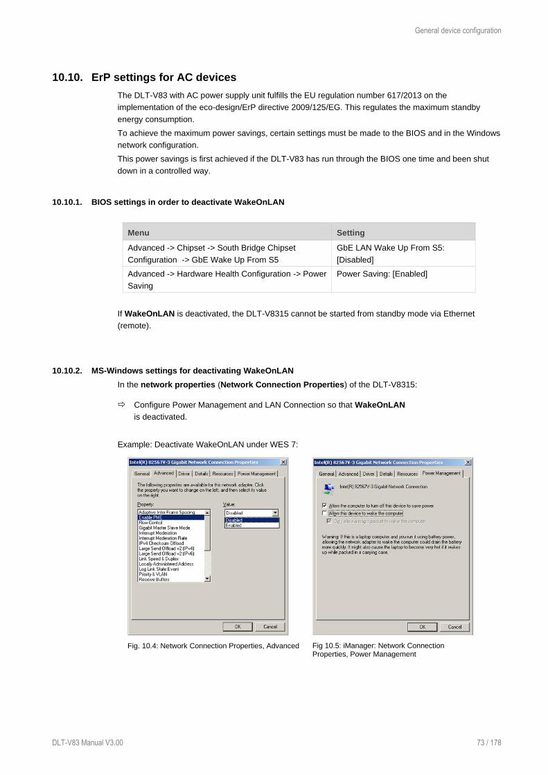
General device configuration
DLT-V83 Manual V3.00 73 / 178
10.10. ErP settings for AC devices
The DLT-V83 with AC power supply unit fulfills the EU regulation number 617/2013 on the
implementation of the eco-design/ErP directive 2009/125/EG. This regulates the maximum standby
energy consumption.
To achieve the maximum power savings, certain settings must be made to the BIOS and in the Windows
network configuration.
This power savings is first achieved if the DLT-V83 has run through the BIOS one time and been shut
down in a controlled way.
10.10.1. BIOS settings in order to deactivate WakeOnLAN
Menu Setting
Advanced -> Chipset -> South Bridge Chipset
Configuration -> GbE Wake Up From S5
GbE LAN Wake Up From S5:
[Disabled]
Advanced -> Hardware Health Configuration -> Power
Saving
Power Saving: [Enabled]
If WakeOnLAN is deactivated, the DLT-V8315 cannot be started from standby mode via Ethernet
(remote).
10.10.2. MS-Windows settings for deactivating WakeOnLAN
In the network properties (Network Connection Properties) of the DLT-V8315:
Configure Power Management and LAN Connection so that WakeOnLAN
is deactivated.
Example: Deactivate WakeOnLAN under WES 7:
Fig. 10.4: Network Connection Properties, Advanced
Fig 10.5: iManager: Network Connection Properties, Power Management

General device configuration
74 / 178 DLT-V83 Manual V3.01
Settings for activating WakeOnLAN
Example: Activate WakeOnLAN under WES 7:
Fig. 10.6: Network Connection Properties, Advanced
Fig 10.7: iManager: Network Connection Properties, Power Management
Fig. 10.8: Network Connection Properties, Advanced
10.10.3. Power options
To optimize the power consumption of the DLT-V83, adapt the power options accordingly. Relevant
settings:
− Time until the DLT-V83 automatically switches to power-saving mode.
− Time until the screen switches off automatically.

General device configuration
DLT-V83 Manual V3.00 75 / 178
10.11. MPair
With the help of the MPair application Bluetooth® capable 2D scanners can be connected to the terminal
by scanning an onscreen barcode.
This function is only available for industrial computers of the DLT-V72 and DLT-
V83 series, which are equipped with the WLAN Card SPARKLAN WPEQ-261ACN
(BT).
MPair supports the following operating systems.
− Windows 10 IoT Enterprise 2016
− Windows 10 IoT Enterprise 2019
MPair only supports the connection of scanners with the Bluetooth® profile SPP
“Serial-Port-Profile”. USB-HID Bluetooth® connections are not supported by
MPair.
For a more detailed description of the configuration to be made and the handling of the MPair
application, please refer to the separately available ADLoG Config manual v530 (or higher) from our
homepage.
www.advantech-service-iot.eu -> Downloads -> Service -> Paperwork -> Manual

WLAN configuration
76 / 178 DLT-V83 Manual V3.01
11. WLAN configuration
11.1. Safety notice
CAUTION
Danger of radiation emission.
DLT-V83 devices with radio technology emit high frequency energy (abbreviation: HF). To protect
persons against HF radiation:
Mount the DLT-V83 so that persons and domestic animals maintain a minimum distance
of 20 to 50 cm from the radio antennas.
Ensure that persons observe this minimum distance when operating the DLT-V83.
High frequency energy can interfere with technical devices. For this reason, do not use the DLT-V83
in the vicinity of pacemakers or other medical devices.
Only operate the DLT-V83 with radio modules that are approved by the manufacturer for this device.
Make sure that the transmission power and the radio frequency of the DLT-V83 comply with the
regulations for the respective country where the device is deployed.
Observe all applicable regulations for your deployment location/country with regard to operating
channels, radio frequencies and the maximum permissible transmitting power. Responsibility for this
lies with the company operating the DLT-V83. The regulatory authorities in the relevant country can
provide information on this.
Any modifications to the DLT-V83 which are not expressly approved by the party responsible for the
compliance can lead to the withdrawal of the operating license for this device.
Examples of country-specific regulations:
Region: Radio approval:
EU RED (formerly R&TTE)
Canada Canada IC
USA FCC
Antenna solutions for use in Germany
The Advantech antenna solutions are based on the prevailing IEEE 802.11 standard. This standard
allows radio data transfer at rates from 1 Mbps to 54 Mbps (300 Mbps if using IEEE 802.11n) using the
2.4 GHz and 5 GHz frequency band.
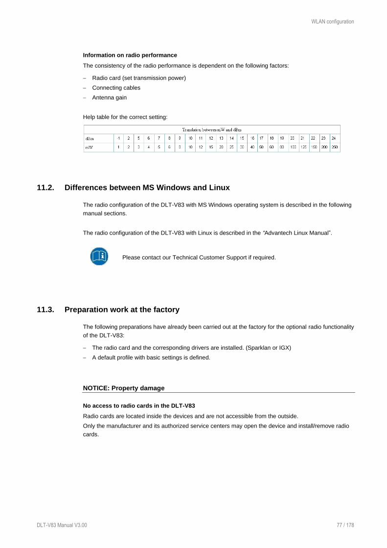
WLAN configuration
DLT-V83 Manual V3.00 77 / 178
Information on radio performance
The consistency of the radio performance is dependent on the following factors:
− Radio card (set transmission power)
− Connecting cables
− Antenna gain
Help table for the correct setting:
11.2. Differences between MS Windows and Linux
The radio configuration of the DLT-V83 with MS Windows operating system is described in the following
manual sections.
The radio configuration of the DLT-V83 with Linux is described in the “Advantech Linux Manual”.
Please contact our Technical Customer Support if required.
11.3. Preparation work at the factory
The following preparations have already been carried out at the factory for the optional radio functionality
of the DLT-V83:
− The radio card and the corresponding drivers are installed. (Sparklan or IGX)
− A default profile with basic settings is defined.
NOTICE: Property damage
No access to radio cards in the DLT-V83
Radio cards are located inside the devices and are not accessible from the outside.
Only the manufacturer and its authorized service centers may open the device and install/remove radio
cards.

WLAN configuration
78 / 178 DLT-V83 Manual V3.01
11.4. Customer-specific settings
To create a customer-specific profile:
Use the configuration program that is already factory-installed on the DLT-V83. (Sparklan or IGX)
Observe the description of the configuration programs in the following sections.
Radio card Operating
system
Configuration program
SUMMIT/LAIRD
SDC-PE15N
Windows
Laird Connection Manager (LCM)
Password: SUMMIT (upper case mandatory)
Wireless Zero Configuration (abbreviation:
WZC)
No password required
SPARKLAN
WPEQ 261 ACN
(BT)
Qualcomm Atheros
QCA61x4A Wireless
Network Adapter
Windows
Advantech WLAN Client Manager (IGX Tool)
Password: gold
Wireless Zero Configuration (abbreviation:
WZC)
No password required
Linux Linux Configuration Utility
11.5. Windows Zero Configuration (WZC)
WZC (Windows Zero Configuration) is a tool for automatic WLAN configuration in MS Windows.
Comprehensive information can be found in the online help for the program.
Using the Sparklan WLAN driver, the WZC tool is used to connect and set up the
WLAN profile as described in more detail in the next chapter.

WLAN configuration
DLT-V83 Manual V3.00 79 / 178
11.6. Sparklan WLAN driver
11.6.1. Area of application
This chapter describes the Sparklan WLAN driver under the following OS:
− Win7Pro
− WinEmbStd7
− Win10IoTEnt
Required: DLT-V83 with radio card SPARKLAN WPEQ-261ACN (BT) MiniPCIe
11.6.2. Requirements
The currently available Sparklan WLAN driver can be downloaded from the following website:
www.advantech-service-iot.eu -> Downloads -> Service -> Drivers -> Link to FTP:
Advantech-DLoG_Products\Additional-Drivers-
Software\WLAN_driver\X86_(DLoG_MPC_MTC_IPC_series\Sparklan_261_ACN_BT
Once the download has completed, the contents of the ".zip" directory on the desktop must be unzipped.
NOTES
The following steps should be performed as the Administrator for the installation process.

WLAN configuration
80 / 178 DLT-V83 Manual V3.01
11.6.3. After image reinstallation: Driver installation
If the image has been reinstalled, the DLT-V83 must be set up again using the Sparklan WLAN driver.
Two drivers are available:
− Driver for Win7Pro \ WinEmbStd7
− Driver for Win10IoTEnt
11.6.4. “Standard” Driver installation WinEmbStd7 / Win7Pro / Win 10 IoTEnt
Open the corresponding installation directory depending on the operating system.
Run Setup.exe to start the installation.
NOTE
The following installation example shows the Win8.1 IndPro \ Win 10 IoT driver.
For Windows7 installation, please use the corresponding Win7 driver.
Fig.11.1: Setup.exe for 64 bit operating system Win10IoTEnt (Sparklan WLAN)

WLAN configuration
DLT-V83 Manual V3.00 81 / 178
Fig.11.2: Setup.exe Choose Setup Language (Sparklan WLAN)
Select the language and continue with Next.
Fig.11.3: Sparklan WLAN driver installation Welcome dialog
Continue the installation with Next.

WLAN configuration
82 / 178 DLT-V83 Manual V3.01
Fig.11.4: Sparklan WLAN driver installation starts
Continue the installation of the required files with Install.
Fig.11.5: Sparklan WLAN driver installation Exit with Finish
Exit the driver installation with Finish.
The WLAN configuration is then carried out using the WZC tool under Windows.
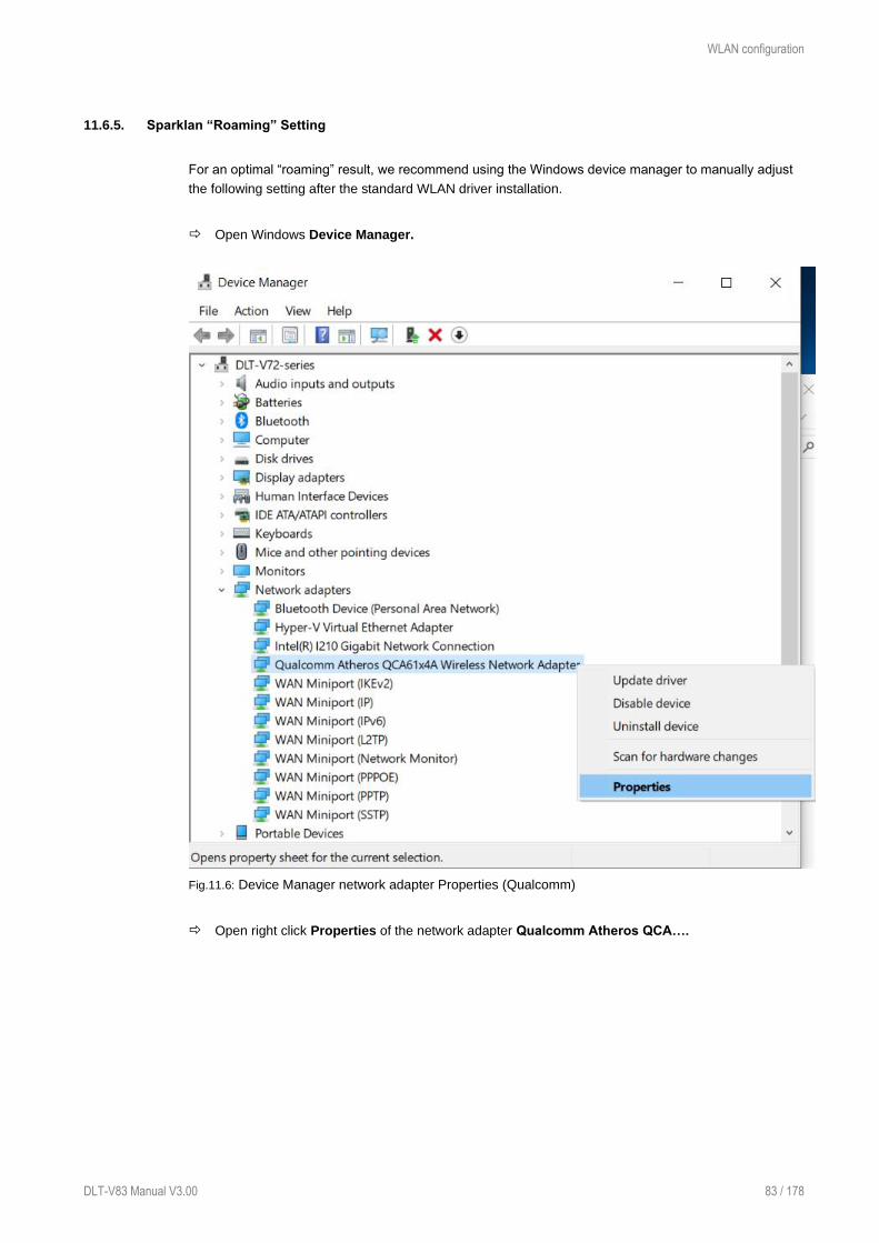
WLAN configuration
DLT-V83 Manual V3.00 83 / 178
11.6.5. Sparklan “Roaming” Setting
For an optimal “roaming” result, we recommend using the Windows device manager to manually adjust
the following setting after the standard WLAN driver installation.
Open Windows Device Manager.
Fig.11.6: Device Manager network adapter Properties (Qualcomm)
Open right click Properties of the network adapter Qualcomm Atheros QCA….
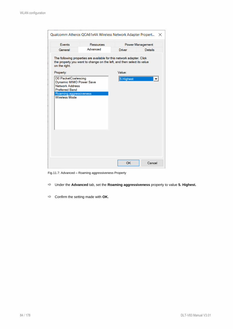
WLAN configuration
84 / 178 DLT-V83 Manual V3.01
Fig.11.7: Advanced – Roaming aggressiveness Property
Under the Advanced tab, set the Roaming aggressiveness property to value 5. Highest.
Confirm the setting made with OK.

WLAN configuration
DLT-V83 Manual V3.00 85 / 178
11.7. Sparklan BT driver
In addition to the WLAN driver, Sparklan provides a suitable Bluetooth® driver separately.
11.7.1. Area of application
This chapter describes the Sparklan BT driver under the following OS:
− Win10IoTEnt
Required: DLT-V83 with radio card SPARKLAN WPEQ-261ACN (BT) MiniPCIe.
11.7.2. Requirements
The currently available Sparklan BT driver can be downloaded from the following website:
www.advantech-service-iot.eu -> Downloads -> Service -> Drivers -> Link to FTP:
Advantech-DLoG_Products\Additional-Drivers-
Software\WLAN_driver\X86_(DLoG_MPC_MTC_IPC_series\Sparklan_261_ACN_BT
Once the download has completed, the contents of the ".zip" directory on the desktop must be unzipped.
NOTES
The installation of the Sparklan BT driver is only approved in conjuction with the Sparklan WLAN driver.
Using the IGX WLAN driver, the appropriate BT driver is installed automatically!
The following steps should be performed as the Administrator for the installation process.
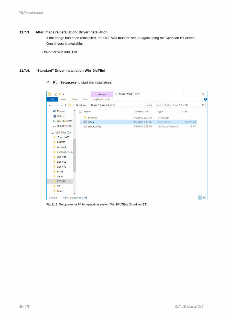
WLAN configuration
86 / 178 DLT-V83 Manual V3.01
11.7.3. After image reinstallation: Driver installation
If the image has been reinstalled, the DLT-V83 must be set up again using the Sparklan BT driver.
One drivers is available:
− Driver for Win10IoTEnt
11.7.4. “Standard” Driver installation Win10IoTEnt
Run Setup.exe to start the installation.
Fig.11.8: Setup.exe for 64 bit operating system Win10IoTEnt (Sparklan BT)
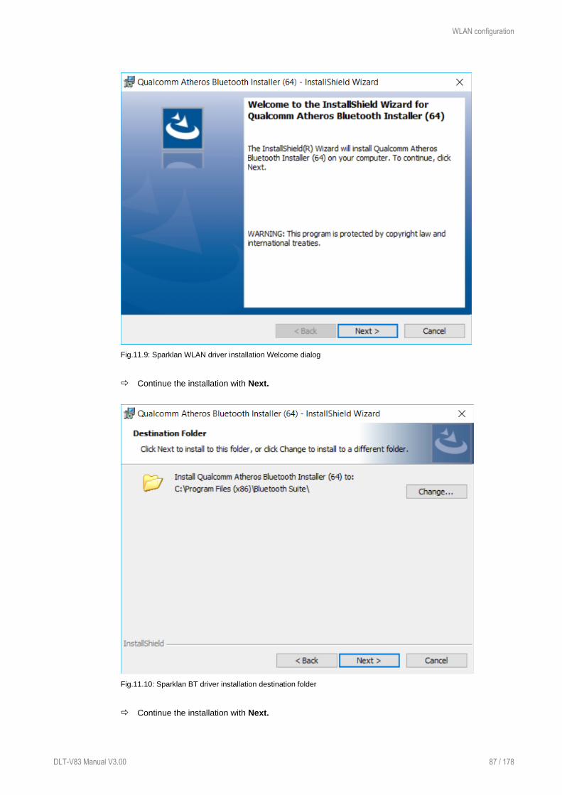
WLAN configuration
DLT-V83 Manual V3.00 87 / 178
Fig.11.9: Sparklan WLAN driver installation Welcome dialog
Continue the installation with Next.
Fig.11.10: Sparklan BT driver installation destination folder
Continue the installation with Next.
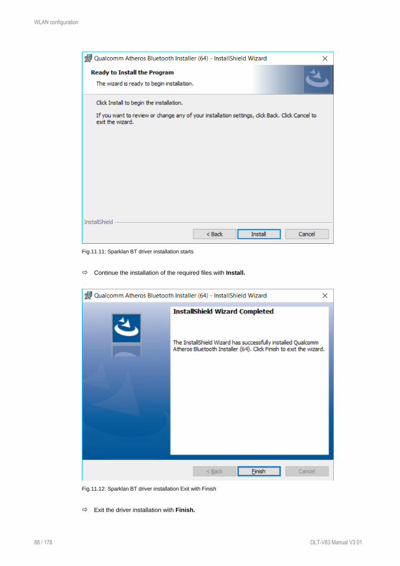
WLAN configuration
88 / 178 DLT-V83 Manual V3.01
Fig.11.11: Sparklan BT driver installation starts
Continue the installation of the required files with Install.
Fig.11.12: Sparklan BT driver installation Exit with Finish
Exit the driver installation with Finish.

WLAN configuration
DLT-V83 Manual V3.00 89 / 178
It is recommended to restart the system immediately after the installation.
Fig.11.13: Sparklan BT driver installation perform system restart
Continue with Yes.
The system restart is being performed.

WLAN configuration
90 / 178 DLT-V83 Manual V3.01
11.8. Advantech WLAN Client Manager (IGX Tool)
11.8.1. Area of application
This chapter describes the Advantech WLAN Client Manager program version 1.02 under the following
operating systems:
− Win7Pro
− WES7
− Win10IoTEnt
This chapter applies to DLT-V83 devices with the Radio card "SPARKLAN WPEQ-261ACN(BT)
MiniPCIe".
11.8.2. Program version 1.01 (new features)
The Advantech WLAN Client Manager program version 1.01 offers the following new features:
− Optimized “silent” installer /
− “Silent uninstaller” (does not require user interaction during whole process)
− “Import / Export” feature of current configured wireless settings + profiles
11.8.3. Program version 1.02 (new features)
The Advantech WLAN Client Manager program version 1.02 offers the following new features:
− Optimized “silent” installer / uninstaller
− Setup.exe GUI installation dismissed
− WES7 OS specific “PreInstall.bat” requirement dismissed
− Logging functionality added (allows capturing roaming details for debug purpose)
− Updated threshold values for default “fast roaming behaviour”
− Updated WLAN driver version v11.0.0.627
11.8.4. Driver download
The currently available IGX drivers can be downloaded from the following website:
www.advantech-service-iot.eu -> Downloads -> Service -> Drivers -> Link to FTP:
Advantech-DLoG_Products\Additional-Drivers-
Software\WLAN_driver\X86_(DLoG_MPC_MTC_IPC_series\Sparklan_261_ACN_BT
Once the download has completed, the contents of the ".zip" directory on the desktop must be unzipped.
NOTES
The IGX driver needs a valid license.
The following steps should be performed as the Administrator for the installation process.

WLAN configuration
DLT-V83 Manual V3.00 91 / 178
11.8.5. After image reinstallation: Driver installation
If the image has been reinstalled, the DLT-V83 must be set up again using the IGX WLAN driver.
Two drivers are available:
− Driver for Win7Pro and WES7
− Driver for Win10IoTEnt
11.8.6. “Silent” Driver installation WES7 / Win7Pro / Win10IoTEnt
Open the corresponding installation directory depending on the operating system.
Run Silent_Install.bat (Run as administrator) to start the installation.
Confirm the Windows UAC (User-Account-Control) message.
The installation process will be done automatically in background and takes around 2 minutes.
At the end of process, no dialog will be shown to user and system restart is required.
NOTE
Please allow 2 minutes waiting time that process can be finished successfully before restarting the
system.
11.8.7. “Silent” Driver uninstaller WES7 / Win7Pro / Win10IoTEnt
Open the corresponding installation directory depending on the operating system.
Run Silent_UnInstall.bat (Run as administrator) to start the uninstall process.
Confirm the Windows UAC (User-Account-Control) message.
The uninstall process will be done automatically in background and takes around 2 minutes.
At the end of process, no dialog will be shown to user and system restart is required.
NOTE
Please allow 2 minutes waiting time that process can be finished successfully before restarting the
system.
Please use ONLY the prepared batch file for the uninstall process and NOT the standard Windows
Add / Remove programs function!
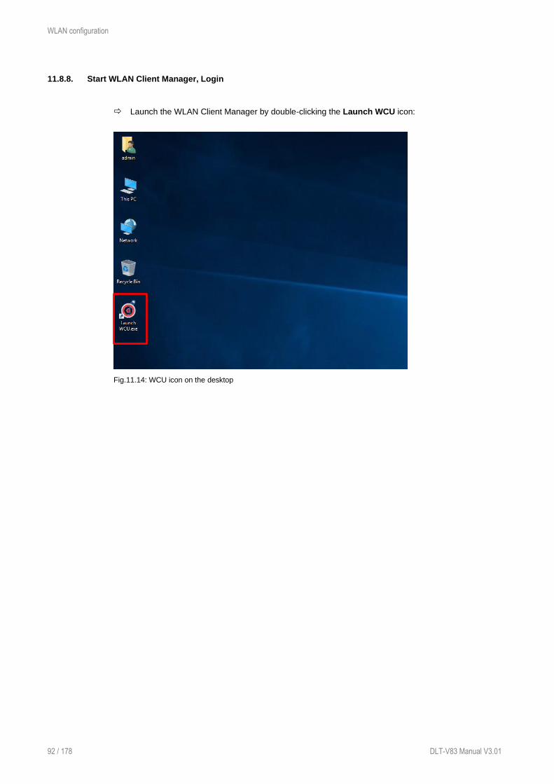
WLAN configuration
92 / 178 DLT-V83 Manual V3.01
11.8.8. Start WLAN Client Manager, Login
Launch the WLAN Client Manager by double-clicking the Launch WCU icon:
Fig.11.14: WCU icon on the desktop

WLAN configuration
DLT-V83 Manual V3.00 93 / 178
You must login as "WCU_Administrator" first.
To do this, click Admin Login.
Fig.11.15: WCU main window, Admin Login
Then open the login window.
Enter the passport, which by default is "gold".
Confirm the input with the Login button.

WLAN configuration
94 / 178 DLT-V83 Manual V3.01
Fig.11.16: WCU-Administrator login window
After successful Admin-login, speed buttons for managing profiles are available:
Fig.11.17: Speed buttons for managing profiles

WLAN configuration
DLT-V83 Manual V3.00 95 / 178
11.8.9. WLAN Client Manager functions
11.8.9.1. License
The License function lists the current status of the enabled options:
Fig.11.18: Check License
NOTE
The correct implementation of the WLAN driver requires a valid license in combination with
the DLT-V83 terminal.
If, as shown in the image, the license information is missing:
Contact technical customer support to solve the problem.
Fig.11.19: Info display via existing license

WLAN configuration
96 / 178 DLT-V83 Manual V3.01
11.8.10. Browse nearby wireless networks
11.8.10.1. Set up the WLAN connection
To set up a WLAN connection, you can show all available networks using the Browse nearby wireless
networks function.
You can select the appropriate network from here.
Double-click a network name (SSID).
Dialog Create new profile is available now.
Fig.11.20: Browse nearby wireless networks function

WLAN configuration
DLT-V83 Manual V3.00 97 / 178
11.8.10.2. Define security settings
The security settings must be selected (depending on the network).
These settings can be made in the Advanced Security Settings section:
Fig.11.21: Advanced Security Settings dialog
To be able to connect with the network automatically, set the checkmark to connect automatically
when the network is in range:
Fig.11.22: Connection when the network is in range dialog

WLAN configuration
98 / 178 DLT-V83 Manual V3.01
Available parameters in the Connection and Security sections:
Connection
Connect automatically when
the network is in range
Enable this parameter to set up an automatic connection to
the network.
Connect to a more preferred
network if available
In the event of multiple profiles being present, this option can
be used to select the preferred profile.
Connect even if the network
is not broadcasting its name
(ssid)
This option can be used to set that a connection is still
established when the name of the network is not being
transmitted.
The Security settings must be adapted. These settings differ depending on the network.
The Security Type must be selected first. The following options are available:
− No authentication (Open)
− WPA2-Personal
− WPA2-Enterprise
− CCKM
The encryption process (Encryption Type) is selected then. The options available here depend on the
selected Security Type.
− None
− WEP
− AES
This results in the following selection options and settings:
Fig.11.23: Security settings - network authentication methods

WLAN configuration
DLT-V83 Manual V3.00 99 / 178
The network authentication methods shown, as well as their designations, differ depending on the
operating system used.
For the remaining settings as in the case shown above (Cisco: Leap), the required additional
parameters are carried out using the two buttons Settings and Advanced settings.
Fig.11.24: Security settings – Advanced settings (Cisco: Leap)
Fig.11.25: Security settings – LEAP properties

WLAN configuration
100 / 178 DLT-V83 Manual V3.01
Lastly, the network key must be entered in the following example (WPA2-Personal) (Network
Security Key).
Confirm the settings with OK.
Fig.11.26: Wireless Network properties dialog
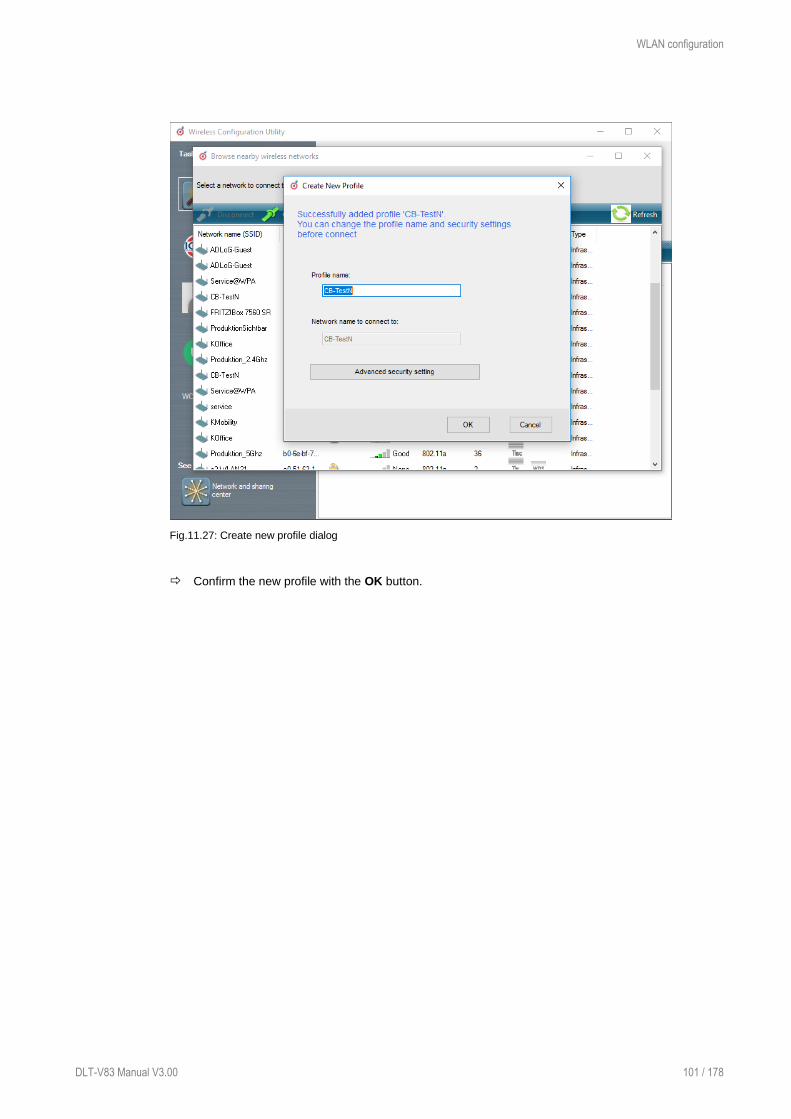
WLAN configuration
DLT-V83 Manual V3.00 101 / 178
Fig.11.27: Create new profile dialog
Confirm the new profile with the OK button.

WLAN configuration
102 / 178 DLT-V83 Manual V3.01
11.8.10.3. Establish network connection
After the WLAN profile settings have been made, a connection to the network is established
automatically.
The connection setup with the selected network is successful only if the "green" connection line is
displayed in the WCU main window.
Fig.11.28: Network connection is established

WLAN configuration
DLT-V83 Manual V3.00 103 / 178
11.8.11. Roam Management
11.8.11.1. General
After clicking the General dialog, the following information is displayed on the screen:
Fig.11.29: General dialog in the Roam Management menu
General
Info Meaning of the display
Client Status Current connection status: Connected / Disconnected
Network Name SSID SSID of the currently connected access points
Network Type Network type Ad-hoc or Infrastructure
AP BSSID Corresponding MAC address of the currently connected access
points
Channel Displays the configured channel used in the access point
Mode Frequency band used, e.g. "802.11g"
Signal Strength (dBm) Current signal strength of the connected access points in (dBm)
SNR Relative signal strength (SNR) as bar chart
Radio Power on Time (sec) Display of the current elapsed operating time of the Radio card
Country Code The country code supplied by the access point such as US, DE, JP
IP Address The Client IP address configured by the access point (DHCP) or
manually (static) assigned
CCX AP Name SSID of the Cisco CCX Access Points (if present)
Security
Authentication The authentication process used, e.g. WPA2-PSK (Pre-Shared-Key)
Encryption Display of the corresponding encryption process, e.g. (AES-CCMP, TKIP)

WLAN configuration
104 / 178 DLT-V83 Manual V3.01
11.8.11.2. Roaming
The Roaming dialog is used to define the following parameters:
Fig.11.30: Roaming dialog in the Roam Management menu
Roam
Signal Level (dBm): The client decides to roam only when the current signal strength is
weaker than the setting value and the new visible access point has higher
signal strength (defined in Roam RSSI Difference).Possible values: -55
dBm to -80 dBm
Default value: -70 dBm (adjustable in 5 dBm increments)
Minimum Connection
Time (sec)
This setting defines how long the client is to remain connected to the
current access point before roaming to the new access point starts.
Possible values: 5 to 25 seconds
Default value: 10 seconds
Logging Enable
Level
This setting can be used to define that the activities of the driver are
recorded in a log. Two levels are available: Critical and All.
Critical: If the debug level is set to Critical, only the critical messages
from the driver will be recorded.
All: If the debug level is set to All, all messages from the driver will be
recorded.
The log file is saved in the C:\WlanLogs folder and a current timestamp
is added.
If the log file is larger than 100 mb, a new file is created.
NOTE: This option should only be enabled for short periods for analysis
purposes, not permanently!

WLAN configuration
DLT-V83 Manual V3.00 105 / 178
Firmware Logging Option can be enabled to create a "Firmware" log.
The log file is saved to the C:\WlanLogs folder and is assigned the current
timestamp and the extension _fw.
If the log file is larger than 100 mb, a new file is created.
NOTE: This option should only be enabled for short periods for analysis
purposes, not permanently!
Roam RSSI
Difference (dBm)
The client will not connect to the new access point until the defined RSSI
difference between the new visible access point and the currently connected
access point is reached. Proper difference could avoid unnecessary roaming
frequency.
Possible values: 5 dBm to 25 dBm
Default value: 5 dBm
Background Scan
Signal Level (dBm) The client begins the background scan only when the current signal
strength is weaker than the setting value.
Possible values: -55 dBm to -80 dBm
Default value: -65 dBm
Probe request
interval
This setting is used to define how frequently the probes are to be sent
when the client is in the "Connected" status.
The minimum value here is 1 second.
The maximum value is 10 seconds.
Each scan process (repetition) takes 4 to 5 seconds.
Clicking the Choose Band and Channels button opens the following dialog:
Fig.11.31: Roam Management – Choose Band and Channels

WLAN configuration
106 / 178 DLT-V83 Manual V3.01
Channel List
Select all 2.4Ghz
channels
This option can be used for simultaneous pre-selection of all 2.4 GHZ
channels 1 to 13 supported by the WLAN driver.
Modifications to individual channels can be carried out at any time by
clicking the checkboxes for each channel.
NOTICE: Country-specific channel settings / residual restrictions on the
use of special channels should be set according to the legal guidelines
and must be observed!
Select all 5Ghz
channels
This option can be used for simultaneous pre-selection of all 5 GHZ
channels 36 to 140 supported by the WLAN driver.
Modifications to individual channels can be carried out at any time by
clicking the checkboxes for each channel.
NOTICE: Country-specific channel settings / residual restrictions on the
use of special channels should be set according to the legal guidelines
and must be observed!
Select all channels Used to select or de-select the complete channel list 2.4/5 GHZ (to
simplify channel selection).
Band The following selection options are available:
− 2.4 GHz
− 5 GHz
− Dual band (2.4 GHz and 5 GHz)
The corresponding settings mean that only channels occurring in the
frequency band are displayed for selection and de-selection.
CCX Control
CCX / CCKM The CCX specification (Cisco®Compatible eXtensions) contains a series
of functional extensions to the IEEE 802.11 WLAN standard to support
rapid roaming (CCKM): with improved security, reliability and diagnostic
performance.
The CCX specification is a brand from Cisco® and requires a license
agreement to be able to equip mobile devices with this technology.
Currently the CCX versions 4 (CCXv4) and 5 (CCXv5) are supported.
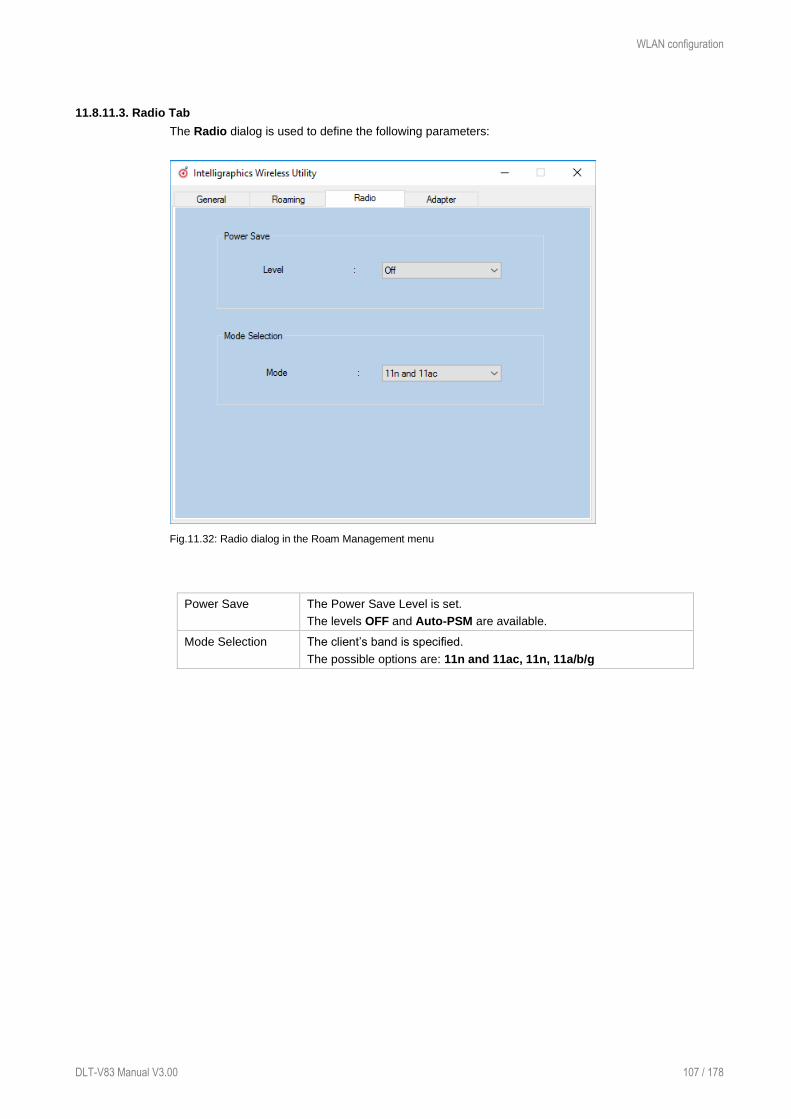
WLAN configuration
DLT-V83 Manual V3.00 107 / 178
11.8.11.3. Radio Tab
The Radio dialog is used to define the following parameters:
Fig.11.32: Radio dialog in the Roam Management menu
Power Save The Power Save Level is set.
The levels OFF and Auto-PSM are available.
Mode Selection The client’s band is specified.
The possible options are: 11n and 11ac, 11n, 11a/b/g

WLAN configuration
108 / 178 DLT-V83 Manual V3.01
11.8.11.4. Adapter Tab
After clicking the Adapter dialog, the following information is displayed on the screen:
Fig.11.33: Adapter Tab in Roam Management menu

WLAN configuration
DLT-V83 Manual V3.00 109 / 178
11.8.12. Import / Export feature
This feature in program version 1.01 (or higher) allows export and import of configured WLAN profiles
and settings.
The „OutputFile.txt“ contains the following saved information:
− Roam parameters: Roam RSSI difference, Signal Level, Min Connection Time
− Background Scan Parameters: Signal Level, Probe Request Interval
− Band and Channel list
− CCX control state
− Radio Tab: Power Save Level and Mode
To start importing or exporting wlan configuration file including all defined profiles click at “Import / Export
button.
Fig.11.34: Import/Export feature
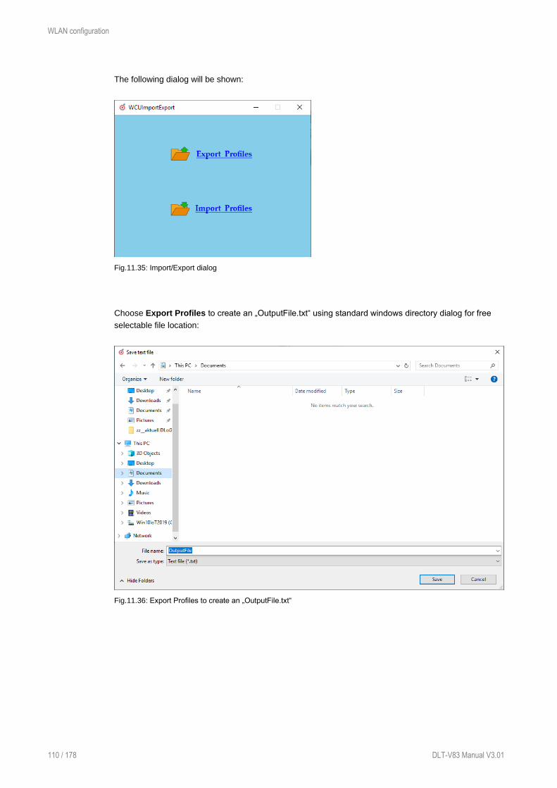
WLAN configuration
110 / 178 DLT-V83 Manual V3.01
The following dialog will be shown:
Fig.11.35: Import/Export dialog
Choose Export Profiles to create an „OutputFile.txt“ using standard windows directory dialog for free
selectable file location:
Fig.11.36: Export Profiles to create an „OutputFile.txt“

WLAN configuration
DLT-V83 Manual V3.00 111 / 178
With button Save „OutputFile.txt“ will be generated followed by message:
Fig.11.37: Info box Profiles exported
Import process requires afterwards to select an existing „OutputFile.txt“:
Fig.11.38: Import process - select an existing “OutputFile.txt”
By clicking “Open” button the file will be imported (existing setup will be overwritten during this process!)
Fig.11.39: Info box Profiles exported

WLAN configuration
112 / 178 DLT-V83 Manual V3.01
“Auto” Import wireless settings file as part of “silent” driver installation
This option is useful for multiple installation scenarios to skip the graphical dialog that requires admin
login to import the wireless setting automatically as part of “silent” driver installation process.
Rename the „OutputFile.txt“ file to → “config.txt”
Place the file into the following directory part of driver installation:
Fig.11.40: Record files
Driver installer path is variable, example:
\\%Driver_Installer%\RecordFiles\config.txt
Run Silent_Install.bat from driver installation root directory to start the installation, the wireless
profiles and settings will be installed next to driver.

WLAN configuration
DLT-V83 Manual V3.00 113 / 178
After the required reboot the wireless connection will be set up automatically based on imported settings:
Fig.11.41: Record files
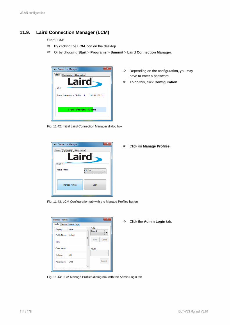
WLAN configuration
114 / 178 DLT-V83 Manual V3.01
11.9. Laird Connection Manager (LCM)
Start LCM:
By clicking the LCM icon on the desktop
Or by choosing Start > Programs > Summit > Laird Connection Manager.
Depending on the configuration, you may
have to enter a password.
To do this, click Configuration.
Fig. 11.42: Initial Laird Connection Manager dialog box
Click on Manage Profiles.
Fig. 11.43: LCM Configuration tab with the Manage Profiles button
Click the Admin Login tab.
Fig. 11.44: LCM Manage Profiles dialog box with the Admin Login tab

WLAN configuration
DLT-V83 Manual V3.00 115 / 178
Default password: SUMMIT
(Must be entered in upper-case characters.)
Fig. 11.45: Entering the LCM password: SUMMIT

WWAN configuration
116 / 178 DLT-V83 Manual V3.01
12. WWAN configuration
12.1. Safety notice
CAUTION
Danger of radiation emission.
DLT-V83 devices with radio technology emit high frequency energy (abbreviation: HF). To protect
persons against HF radiation:
Mount the DLT-V83 so that persons and domestic animals maintain a minimum distance
of 20 to 50 cm from the radio antennas.
Ensure that persons observe this minimum distance when operating the DLT-V83.
High frequency energy can interfere with technical devices. For this reason, do not use the DLT-V83
in the vicinity of pacemakers or other medical devices.
Only operate the DLT-V83 with radio modules that are approved by the manufacturer for this device.
Make sure that the transmission power and the radio frequency of the DLT-V83 comply with the
regulations for the respective country where the device is deployed.
Observe all applicable regulations for your deployment location/country with regard to operating
channels, radio frequencies and the maximum permissible transmitting power. Responsibility for this
lies with the company operating the DLT-V83. The regulatory authorities in the relevant country can
provide information on this.
Any modifications to the DLT-V83 which are not expressly approved by the party responsible for the
compliance can lead to the withdrawal of the operating license for this device.
Examples of country-specific regulations:
Region: Radio approval:
EU RED (formerly R&TTE)
Canada Canada IC
USA FCC
Antenna solutions for use in Germany
The Advantech antenna solutions are based on the prevailing IEEE 802.11 standard. This standard
allows radio data transfer at rates from 1 Mbps to 54 Mbps (300 Mbps if using IEEE 802.11n) using the
2.4 GHz and 5 GHz frequency band.

WWAN configuration
DLT-V83 Manual V3.00 117 / 178
Information on radio performance
The consistency of the radio performance is dependent on the following factors:
− Radio card (set transmission power)
− Connecting cables
− Antenna gain
Help table for the correct setting:
12.2. Differences between MS Windows and Linux
The radio configuration of the DLT-V83 with MS Windows operating system is described in the following
manual sections.
The radio configuration of the DLT-V83 with Linux is described in the “Advantech Linux Manual”.
Please contact our Technical Customer Support if required.
12.3. Preparation work at the factory (DLT-V83 delivery status)
The following preparations have already been carried out at the factory for the optional WWAN
functionality of the DLT-V83:
− The WWAN card and the corresponding drivers are installed.
− GNSS is enabled at the factory
NOTICE: Property damage
No access to radio cards in the DLT-V83
Radio cards are located inside the devices and are not accessible from the outside.
Only the manufacturer and its authorized service centers may open the device and install/remove radio
cards.
WWAN configuration
118 / 178 DLT-V83 Manual V3.01
12.4. SIM card for WWAN (customer-specific)
A SIM card is required in addition to the WWAN card.
The SIM card must be plugged in by the client into the SIM card slot underneath the DLT-V83 antenna.
NOTICE: Property damage
Inserting the SIM card: DLT-V83 must be switched off
For more details, see the chapter 8.3 Open/close antenna.
NOTE
If the SIM card contains a PIN, the customer must set up an application for the PIN query.
For this reason, we recommend not using a PIN.
12.5. Configuration of radio card SIERRA WIRELESS MC80
The following information applies for the radio card SIERRA WIRELESS MC80. Its precise designation
is:
− USA: SIERRA WIRELESS MC8090
− Europe: SIERRA WIRELESS MC8092
The WWAN configuration is identical for both Radio cards. For this reason, the abbreviation SIERRA
WIRELESS MC80 is used.
NOTE
In the section below, the provider Vodafone is used as an example.
Adjust the settings for your provider.

WWAN configuration
DLT-V83 Manual V3.00 119 / 178
12.5.1. Open device manager
Check whether or not the Sierra Wireless HSPA Modem is present in the list of modems.
Fig. 12.1: SIERRA WIRELESS MC80 - Device manager, Sierra Wireless HSPA Modem
Display the Properties window of the Sierra Wireless HSPA Modems (left mouse button).
Click the Advanced tab.
In the Advanced tab, enter the APN of the
provider:
e.g. +CGDCONT=1,"IP","web.vodafone.de"
Then click OK.
Fig. 12.2: SIERRA WIRELESS MC80 - Sierra Wireless HSPA Modem - Properties
12.5.2. Establish Internet connection
Open the Network and Sharing
Center.
Click Set up a new connection or
network.
Fig. 12.3: SIERRA WIRELESS MC80 - Set up a new connection or network

WWAN configuration
120 / 178 DLT-V83 Manual V3.01
Connect to the Internet - select
and confirm.
Fig. 12.4: SIERRA WIRELESS MC80 - Connect to the Internet
Select the Dial-up field.
Fig. 12.5: SIERRA WIRELESS MC80 - Connect to the Internet - Dial-up
Specify as a telephone number, e.g.
*99***1#.
Enter a connection name, e.g.
Vodafone test connection.
Username and password are not
required in the example (provider-
dependent).
Fig. 12.6: SIERRA WIRELESS MC80 - Telephone number and connection name
Open the Vodafone test connection under Network connections.

WWAN configuration
DLT-V83 Manual V3.00 121 / 178
Fig. 12.7: SIERRA WIRELESS MC80 - Network connections - Vodafone test connection
Do not enter a user name or password.
Click Dial.
The test connection is established.
Fig. 12.8: SIERRA WIRELESS MC80 – Dial test connection
In the Network and activation center of the device, the status of the test connection can be tested:
Right-click the network and then select Status.
Fig. 12.9: SIERRA WIRELESS MC80 - Function test GSM / GNSS, test connection status

WWAN configuration
122 / 178 DLT-V83 Manual V3.01
12.5.3. SIERRA WIRELESS MC80 Trouble Shooting
12.5.3.1. Testing the virtual COM ports for Wireless card SIERRA WIRELESS MC80
In the device manager it is possible to test that the virtual COM ports are correctly set.
If they are not correctly set, they must be modified as appropriate.
DLT-V83 with D525 processor:
The virtual COM ports must be set up as shown in the figure:
Fig. 12.10: SIERRA WIRELESS MC80 - Virtual COM ports DLT-V83 with D525 processor
DLT-V83 with i5 processor:
The virtual COM ports must be set up as shown in the figure:

WWAN configuration
DLT-V83 Manual V3.00 123 / 178
Fig. 12.11: SIERRA WIRELESS MC80 - Virtual COM ports DLT-V83 with i5 processor
DLT-V83 with Celeron processor:
The virtual COM ports must be set up as shown in the figure:
Fig. 12.12: SIERRA WIRELESS MC80 - Virtual COM ports DLT-V83 with Celeron processor

WWAN configuration
124 / 178 DLT-V83 Manual V3.01
12.5.3.2. Test communication between DLT-V83 and WWAN Radio card
The open source software Tera Term, for example, can be used to test that the DLT-V83 can
communicate with the Radio card.
This software can be downloaded from the following URL, for example (website available at time of
writing this operating manual, dated Feb 2019):
https://www.heise.de/download/product/tera-term-51776
Perform the following steps:
Open the AT port via Tera Term.
Connect to the AT port.
In the AT port, enter the command AT.
If the response received is OK, communication is present.
12.5.3.3. Test that GNSS data can be received
The open source software Tera Term, for example, can be used to test that GNSS data can be
received. Availability of the software: see previous section.
Perform the following steps:
Open the NMEA port via Tera Term.
Test that NMEA data are received.
Enabled data flows are displayed.
Example:
Fig. 12.13: SIERRA WIRELESS MC80 - test NMEA data flows

WWAN configuration
DLT-V83 Manual V3.00 125 / 178
12.6. Configuration of Radio card QUECTEL EC25
The following information is valid for the Radio card QUECTEL EC25. Its precise designation is:
− USA: QUECTEL EC25A or EC25V
− Europe: QUECTEL EC25E
The WWAN configuration is identical for both Radio cards. For this reason, the abbreviation QUECTEL
EC25 is used.
12.6.1. Establish Internet connection
NOTE
In the section below, the provider Vodafone is used as an example.
Adjust the settings for your provider.
Open the Network and Sharing
Center.
Click Set up a new connection or
network.
Fig. 12.14: QUECTEL EC25 - Set up a new connection or network
Connect to the Internet - select
and confirm.
Fig. 12.15: QUECTEL EC25 - Connect to the Internet

WWAN configuration
126 / 178 DLT-V83 Manual V3.01
Click Dial-up.
Fig. 12.16: QUECTEL EC25 - Connect to the Internet - Dial-up
Specify as a telephone number, e.g.
*99***1#.
Enter a connection name, e.g.
Vodafone test connection.
Username and password are not
required in the example. (Provider-
dependent)
Fig. 12.17: QUECTEL EC25 - Connect to the Internet - Telephone number
Open the Vodafone test connection under Network connections.
Fig. 12.18: QUECTEL EC25 - Network connections - Vodafone test connection

WWAN configuration
DLT-V83 Manual V3.00 127 / 178
Do not enter a user name or password.
Click Dial.
The test connection is established.
Fig. 12.19: QUECTEL EC25 - Dial Vodafone test connection
In the Network and activation center of the device, the status of the test connection can be tested:
Right-click the network and then select Status.
Fig. 12.20: QUECTEL EC25 - Function test GSM / GNSS, test connection status

WWAN configuration
128 / 178 DLT-V83 Manual V3.01
12.6.2. QUECTEL EC25 Trouble Shooting
12.6.2.1. Test virtual COM ports
In the device manager it is possible to test that the virtual COM ports are correctly set.
If they are not correctly set, they must be modified as appropriate.
DLT-V83 with i5 processor
The virtual COM ports must be set up as shown in the figure:
Fig. 12.21: QUECTEL EC25 - Virtual COM ports DLT-V83 with i5 processor

WWAN configuration
DLT-V83 Manual V3.00 129 / 178
DLT-V83 with Celeron processor
The virtual COM ports must be set up as shown in the figure:
Fig. 12.22: QUECTEL EC25 - Virtual COM ports DLT-V83 with Celeron processor
12.6.2.2. Test communication between DLT-V83 and WWAN Radio card
The open source software Tera Term, for example, can be used to test that the DLT-V83 can
communicate with the Radio card.
This software can be downloaded from the following URL, for example (website available at time of
writing this operating manual, dated Feb 2019):
https://www.heise.de/download/product/tera-term-51776
Perform the following steps:
Open the AT port via Tera Term.
Connect to the AT port.
In the AT port, enter the command AT.
If the response received is OK, communication is present.
12.6.2.3. Test that GNSS data can be received
The open source software Tera Term, for example, can be used to test that GNSS data can be
received. Availability of the software: see previous section.
Perform the following steps:
Open the NMEA port via Tera Term.
Test that NMEA data are received.
Enabled data flows are displayed.

WWAN configuration
130 / 178 DLT-V83 Manual V3.01
Example:
Fig. 12.23: QUECTEL EC25 - Test NMEA data flows
Mechanical mounting
DLT-V83 Manual V3.00 131 / 178
13. Mechanical mounting
13.1. Warning about injuries and Property damage
WARNING
Risk of personal injury and Property damage due to improper installation and
commissioning.
Only authorized skilled personnel are permitted to install and commission the DLT-V83.
Moreover, specialized knowledge about battery packs and the applicable safety regulations is
also required for DLT-V83 Industrial Computers with integrated UPS (optional).
If the DLT-V83 is incorrectly installed and placed into operation, any warranty for this device
will be rendered void.
Risk of injury due to the weight of the device
The DLT-V83 can fall down and cause injuries due to its weight.
Always hold the device by the housing with both hands.
Never use the antenna cap as a handle. It can break due to the weight involved.
Use the assistance of a second person for installation work.
The installation height of the device shall not exceed 2 m.
Risk of injury due to sharp-edged parts on the device
The strain relief rail of the DLT-V83 can have sharp edges and cause cutting injuries.
Do not hold the device by the strain relief rail.
Risk of injury and damage due to improper deployment location.
Observe the intended use of the DLT-V83, e.g. not in potentially explosive areas, not in
life-supporting facilities.
Observe that the deployment location of the DLT-V83 must comply with the permissible
environmental conditions.
The installation height of the device shall not exceed 2 m.
Danger if mounting bracket breaks
When installing the DLT-V83, make sure that no one will be injured if the bracket breaks
(e.g. because of a stress fracture).
Alternatively please put appropriate safety measures in place (e.g. install a security cable
in addition to the mounting bracket).
Radio wave emission in the vicinity of persons.
To ensure that the limits set for exposure to radio waves are not exceeded:
Install the DLT-V83 so that persons maintain a minimum distance of 20 to 50 cm to the
antenna.

Mechanical mounting
132 / 178 DLT-V83 Manual V3.01
NOTICE: Property damage
Installation environment without cooling air can overheat/damage the DLT-V83.
The DLT-V83 employs a passive cooling concept whereby the waste heat generated inside the
device is emitted from the surface of the housing. For this system to function properly, sufficient
fresh air circulation is required.
Never install the system in a closed environment where the cooling air is unable to
dissipate accumulated heat to the outside.
The maximum permissible ambient temperature for the entire system needs to be taken
into account for the specific application area.
Damage and scratching of the touchscreen without transport protective film.
The front display of the DLT-V83 is protected during transport by a transparent film. This film
should remain on the front display during assembly to avoid damage to the front display surface.
Only remove the film after all of the installation work has been completed
13.1.1. Important: Installation of the DLT-V83 on vehicles
WARNING
Observe the requirements of the vehicle manufacturer.
Observe the requirements of the vehicle manufacturer for the attachment of auxiliary
devices and the connection of auxiliary consumers.
Observe all requirements that relate to welding or drilling support parts.
Risk of accident on vehicles due to limited field of view of the driver.
Inside the vehicle the driver's field of vision must remain free.
During installation, plan for sufficient space for the DLT-V83 and accessories.
Make sure that the driver's field of vision is not restricted in a prohibited.
No part of the DLT-V83 system may project beyond the vehicle.
Risk of accident on vehicles due to unexpected vehicle emergency stop because of
electro conductive connection of the DLT-V83 to the vehicle chassis
Due to a variety of technical properties of forklifts and forklift trucks, it can be necessary to
electrically isolate DLT-V83 from the chassis of the vehicle to prevent malfunctions. The
necessity of this must be studied on a case-by-case basis, however, it is recommended for
vehicles with potential-free chassis.
For example, using rubber buffers ensures that the terminal has no electrically conducting
connection to the vehicle chassis.
If peripheral equipment (such as scanners, printers, scales or similar), which has its own power
supply unit is used, you must ensure that the power supply units of these peripherals are
galvanically separated from the supply of the vehicle.
Moreover, the peripheral equipment and its cabling must be attached electrically isolated.
If external antennas are being used, you must ensure that the antennas are isolated at the
mounting point on the vehicle chassis.

Mechanical mounting
DLT-V83 Manual V3.00 133 / 178
13.2. Overview of mounting steps
Requirement: The vehicle/installation location must be prepared (e.g. connection to the ignition,
correct voltage, etc.)
We recommend the following sequence for the mechanical and electrical installation:
− Determine a suitable mounting position for the DLT-V83.
− Secure device mounting (mounting bracket, RAM mount; optional).
− Connect external accessories to the DLT-V83.
− Install an easily accessible disconnecting device, such as a switch.
− Connection to the power supply.
− Seal cable bushings with cable grommets and dummy grommets.
− Close the DLT-V83 with cable cover.
− Mount the DLT-V83 on the device mounting bracket (follow mounting instructions).
13.3. Connecting external accessories to the DLT-V83
The DLT-V83 must be disconnected from the power supply:
− before external devices (e.g. scanner, keyboard) are connected or disconnected.
− before using the interfaces underneath the antenna.
− and before the DLT-V83 is connected to a network.
NOTICE: Property damage
Observe the following when connecting/removing external devices:
Only use accessories that have been tested and approved by Advantech for the respective DLT-
V83.
The DLT-V83 may not be connected to the power supply if external devices are being
connected/removed (not applicable for USB devices). Otherwise considerable damage could be
caused to both the DLT-V83 and the peripheral devices.
Make sure that peripherals with their own power supply are either switched on at the same time as
the DLT-V83 or after the start of the DLT-V83.
Otherwise, you must ensure that a backflow from the external device to the DLT-V83 cannot take
place.
Only power up the DLT-V83 when all devices have been connected and the DLT-V83 has been
closed correctly (remember the cable cover!). Otherwise, you may damage the
DLT-V83.
Please observe the mounting instructions supplied with the optional accessories.

Mechanical mounting
134 / 178 DLT-V83 Manual V3.01
13.4. Attaching device mounting and accessory mounting (optional)
Observe the following information about the mounting brackets:
− All mounting brackets and mounting parts supplied by Advantech are only intended to be used for
attachment of the Industrial Computers and the peripheral devices and may not be misused.
− Only use suitable mounting brackets and screws permitted by Advantech.
− Ensure that ball-and-socket bases and mounting brackets are always attached correctly.
WARNING
Risk of accident on vehicles if the mounting becomes loose.
− Mechanical expert knowledge is required for correct attachment of device mounts and accessory
mounts on the DLT-V83.
− Use suitable mounting material.
− Observe the maximum screw-in depth of the holes of the DLT-V83:
− The recommended screw-in depth of D x 1 always applies (screw diameter x 1).
− NOTICE: Screws that are too long, e.g. in the VESA mounting holes, can pierce the rear side of
the DLT-V83 and cause irreparable damage to the device.
13.4.1. VESA drill holes
VESA-compatible drilling patterns for the RAM attachment and swivel joint brackets are located on the
rear side of the DLT-V83.
DLT-V8310 VESA drill holes
Dimensions without add-ons (in mm)
Depth of thread: M6 x 6mm
Fig. 13.1: Position of the VESA drill holes DLT-V8310

Mechanical mounting
DLT-V83 Manual V3.00 135 / 178
DLT-V8312 VESA drill holes
Dimensions without add-ons (in mm)
Depth of thread: M6 x 6mm
Fig. 13.2: Position of the VESA drill holes DLT-V8312

Mechanical mounting
136 / 178 DLT-V83 Manual V3.01
DLT-V8315 VESA drill holes
Dimensions without add-ons (in mm)
Depth of thread: M6 x 6mm
Fig. 13.3: Position of the VESA drill holes DLT-V8315

Electrical connection
DLT-V83 Manual V3.00 137 / 178
14. Electrical connection
14.1. Connection to the power supply
WARNING
Risk of injury and damage due to improper electrical connection.
Only authorized skilled personnel are permitted to perform the electrical connection of the
DLT-V83. Moreover, specialized knowledge about battery packs and the applicable safety
regulations is also required for DLT-V83 Industrial Computers with integrated UPS (optional).
If the electrical connection of the DLT-V83 is performed improperly, any warranty for this
device will be void.
Comply with the appropriate national installation regulations for the cable routing.
Do not connect/disconnect any cables during thunderstorms.
When working on the cable cover with UPS battery packs you must remove wristwatches,
rings or other metal objects.
Power supply unit fuse blows repeatedly
If the fuse of the integrated power supply units blows again immediately after replacement,
there is a risk of electrical shock:
Send in the DLT-V83 immediately for repair.
Electrical shock due to lack of disconnecting device.
DLT-V83 Industrial Computers are not equipped with disconnecting devices that are accessible
from the outside; they do not have switches. To enable the devices to be quickly disconnected
from the power supply in emergency situations:
Install an easily accessible disconnecting device close to the device.
Make sure that the disconnecting device disconnects all power supply lines.
Please note: For DLT-V83 devices with integrated UPS the device may be in operation despite
the disconnecting device being actuated, since it is supplied with power by the UPS.

Electrical connection
138 / 178 DLT-V83 Manual V3.01
14.2. Connecting DC devices to the power supply
DLT-V83 is available with a galvanically separated, integrated DC power supply. Power is connected to
the back of the device using a Phoenix contact connector. There is no power switch for the mains
voltage.
WARNING
Hazardous voltage, electric shock on the DLT-V83 with DC power supply unit.
Do not put the DLT-V83 into operation if it is damaged.
Do not open or modify the DLT-V83.
Only connect or disconnect electrical connections when the device is in a de-energized
state (electrically dead).
Use only original power supply cables from Advantech. Advantech power cables meet the
specific requirements for low-temperature flexibility, UV resistance, oil resistance, etc.
If other power supply cables are used: The user/operator of the DLT-V83 is solely
responsible for the resulting damage.
Make sure that the power supply cables are run without kinks and are mechanically
protected (securely protected against crushing and abrading).
The DC+ connecting cable must be protected by a fuse (30 AT max.).
The ignition connecting cable must be protected by a fuse of the following type:
5x20 mm T 125 mA L / 250 V, for example, a Wickmann 195-125 mA / 250 V.
Observe correct voltage ranges.
Ensure that power supply cable is fused correctly.
Observe the labeling on the cable and connect the power supply cable with the correct
polarity.
Cut the supply cable to the minimum length. This avoids tangled cables and improves the
quality of the power supply.
Connect the power supply cable to a suitable place. Ensure that the connecting cable has
an adequate cross section and ampacity at the connection point.
DLT-V83 Industrial Computers with DC power supply unit may only be connected to a
SELV circuit (Safety Extra Low Voltage).
Fig. 14.1: DC connection cable with Phoenix contact connector

Electrical connection
DLT-V83 Manual V3.00 139 / 178
14.2.1. Important: Electrical connection of the DLT-V83 to vehicles
DANGER
Danger to life due to electric shock.
Ground the DLT-V83 in accordance with the vehicle manufacturer's instructions.
Observe the vehicle manufacturer’s instructions for connecting additional loads, for
example, in conjunction with an emergency shut-off switch.
Be sure that the connection of the power supply cables is as direct as possible to the
battery and not to power supply cables with a great deal of interference (e.g. the motor
power supply) or otherwise affected by consumers.
Electrical shock due to insufficient EMERGENCY shut-off of the vehicle.
If the EMERGENCY-OFF switch of the vehicle does not switch off the DLT-V83, there is a risk
of electrical shock.
Install the DLT-V83 and the EMERGENCY-OFF switch so that the DLT-V83 also switches
off when the EMERGENCY-OFF switch is operated.
Observe: If a DLT-V83 with integrated UPS is installed in a vehicle, the EMERGENCY-OFF
switch of the vehicle has no effect on the DLT-V83. This also applies to the peripherals
supplied by the device.
14.2.2. Electrical installation of DC devices
Pay special attention to the various electrical potentials when installing the unit on vehicles.
On the DLT-V83, the logic ground and the shield ground are firmly connected to each other.
The “logic ground” is the earth line (GND) for all of the internal electrical components, such as the
display and the CPU.
All cable shields and the housing are connected with the shield ground.
Some forklifts have a chassis that is connected to DC+. Therefore, the DLT-V83 chassis is also
connected to DC+. If peripheral devices supply DC− to the shield connection of the DLT-V83 by a
connection plug, for example over a serial connection, this will cause a short-circuit and malfunctions or
power failures will be unavoidable.
In DC-powered devices, always attach ring tongues on the supply voltage cable to the provided ground
bolt situated on the connector panel (see Fig. 14.2: Position of the ground bolt).
Fig. 14.2: Position of the ground bolt
Ground bolt

Electrical connection
140 / 178 DLT-V83 Manual V3.01
− The other end of the yellow-green power supply cable must be connected to the vehicle’s chassis.
− Connect the power supply cable of the DLT-V83 as close to the battery as possible.
Connecting the DLT-V83 to large electrical loads, such as converters for the forklift motor may result
in random restarts, malfunctions and/or irreparable damage to the device.
− If you want to connect devices fed by other power sources to the DLT-V83 (e.g. printers), be sure to
power up the peripheral devices at the same time or after the DLT-V83; otherwise, you may
encounter start-up problems, malfunctions or even irreparable damage to the device.
14.2.3. Electrically isolated installation of DC devices
DANGER
Risk of accident on vehicles due to unexpected vehicle emergency stop because of
electro conductive connection of the DLT-V83 to the vehicle chassis.
Due to a variety of technical properties of forklifts and forklift trucks, it can be necessary to
electrically isolate DLT-V83 from the chassis of the vehicle to prevent malfunctions. The
necessity of this must be studied on a case-by-case basis, however, it is recommended for
vehicles with potential-free chassis.
For example, using rubber buffers ensures that the terminal has no electrically conducting
connection to the vehicle chassis.
If peripheral equipment (such as scanners, printers, scales or similar), which has its own power
supply unit is used, you must ensure that the power supply units of these peripherals are
galvanically separated from the supply of the vehicle.
Moreover, the peripheral equipment and its cabling must be attached electrically isolated.
If external antennas are being used, you must ensure that the antennas are isolated at the
mounting point on the vehicle chassis.

Electrical connection
DLT-V83 Manual V3.00 141 / 178
14.3. Connecting AC devices to the power supply
An integrated, electrically isolated AC power supply unit is available exclusively for the
DLT-V8315 (optional).
The power is connected to the AC power supply unit on the underside of the device using an angled
power connector for non-heating apparatus.
The cable of the angled power connector is equipped with an On/Off-switch for the power grid.
DANGER
Danger to life due to hazardous voltage, electric shock on the DLT-V83 with AC power
supply unit.
Do not put the device into operation if it is damaged.
Do not open or modify the device.
There is a danger to life if the device is opened while it is connected to the power supply!
Only connect or disconnect electrical connections when the device is in a de-energized
state (electrically dead).
When using the AC adapter, make sure that the sum of the current consumption of the
system, including the consumers connected via I/O (e.g. scanner) does not exceed the
maximum current of the AC adapter, including its supply lines.
14.3.1. Electrical installation of AC devices
When the DLT-V8315 is installed with an AC power supply unit, the electrical potentials must be taken
into account.
The DLT-V8315 is connected to protective ground by means of the power connector for non-heating
apparatus.
In the DLT-V8315, protective ground, logic ground and shield ground are permanently interconnected.
Logic ground is the ground (GND) used to supply the internal parts and components such as the display
or CPU.
All cable shields and the housing are connected to shield ground.
If the terminal is connected to other devices or machines via the existing interfaces (USB, serial,
Ethernet, etc.), ensure that the potential of the relevant protective ground is as equal as possible
(equipotential bonding strip).
Leakage currents (compensating currents) can occur here that may cause random restarts, malfunctions
or even the destruction of the device or peripheral devices.
If you want to connect devices fed by other power sources to the DLT-V8315 (e.g. printers), be sure to
power up the peripheral devices at the same time or after the DLT-V8315; otherwise, you may encounter
start-up problems or malfunctions and there may even be irreparable damage to the device.

Attaching cables and the cable cover
142 / 178 DLT-V83 Manual V3.01
15. Attaching cables and the cable cover
Before commissioning the DLT-V83, the associated cable cover must be attached. The protection class
of the DLT-V83 is only ensured if the cable cover is properly installed.
CAUTION
Risk of injury due to sharp-edged parts on the device.
The strain relief rail of the DLT-V83 can have sharp edges and cause cutting injuries.
Do not hold the DLT-V83 by the strain relief rail.
NOTICE: Property damage
Device not sealed properly due to incorrect attachment of the cables and the cable
cover.
The protection class of the DLT-V83 is only ensured if the cable cover is properly installed.
Improper installation can result in liquid penetrating into the DLT-V83 during operation. There is
then a risk of short-circuiting, corrosion and wear.
15.1. Overview of mounting steps
− All cables that are connected to the DLT-V83 must be fit with the right cable grommets and inserted
in the cable outlets of the strain relief rail.
− The cables are secured to the strain relief rail with cable clips. This prevents the cables from being
loosened at the connection points when too much force is exerted (e.g. during scanning).
− Unused cable entry holes for the strain relief rail must be closed off with dummy grommets.
− The Advantech cable cover must then be secured to the DLT-V83.

Attaching cables and the cable cover
DLT-V83 Manual V3.00 143 / 178
15.2. Required components
− Cable cover of the DLT-V83 (optional with integrated UPS battery packs)
Fig. 15.1: Cable cover with integrated UPS battery (optional)
− 4 fastening screws (cylinder head screws ISO 4762-M4x10-A2)
− Cable clips and mounting screws (cylinder head screws ISO 4762-M3x12-A2)
− Cable sealing set consisting of dummy grommets and gradually widened cable grommets
(3.5 mm to 8.0 mm; in 0.5 mm ascending increments)
Fig. 15.2: Dummy grommets and cable grommets for various cable diameters
Cable grommets, open/broken
through at one position
Diameter of the cable grommet is
specified on each grommet
(3.5 mm to 8.0 mm)
Cable clips
Dummy
grommets

Attaching cables and the cable cover
144 / 178 DLT-V83 Manual V3.01
15.3. Attaching cable grommets and fixing strain relief in place
Important preparatory work
1. Checking the cable diameters and elasticity.
Check the cable diameters and elasticity of all the cables to be connected.
A cable grommet suitable for the diameter and elasticity of the cable must be used.
Bear the following points in mind when selecting a cable grommet:
- The grommet must completely surround the cable.
- The opening of the grommet must be slightly smaller than the cable diameter.
NOTICE: If a grommet is used that is too large or too small, the device will not be properly sealed.
2. Preparing the required cable grommets and dummy grommets.
Remove the required cable grommets and dummy grommets from the cable sealing set (using
scissors, for example).
Cut the grommets off as cleanly as possible at the separation point so that they fit into the cable
openings and seal them tightly.
Cable grommets and dummy grommets should be cut off as cleanly as possible. This is important in
order to seal the Industrial Computer well.
Correct:
Incorrect:
Fig 15.3: Cable grommets and dummy grommets

Attaching cables and the cable cover
DLT-V83 Manual V3.00 145 / 178
Further procedure:
Connect the appropriate
cable grommets to all cables
that will be connected to the
DLT-V83.
Fig. 15.4: Example cable grommet
Insert all cables into the DLT-V83 connection points.
Insert the cable grommets and cables into the outlets of the strain relief rail.
Tips for running the cables:
Try to make a small bend (a loop) when laying the cables. This supports the strain relief and
prevents the cables from being loosened at the connection points when too much force is
exerted.
Exception:
The power supply cable is relatively
stiff and should be straight (see
figure).
Try to lay all cables parallel to
each other without crossing
each other.
Fig. 15.5: The power supply cable, fit with a cable grommet, in the strain relief rail
Close off the unused cable
outlets with dummy grommets.
Fig. 15.6: Unused cable outlets sealed off

Attaching cables and the cable cover
146 / 178 DLT-V83 Manual V3.01
Secure all cables with cable clips
and cylinder head screws ISO
4762-M3x12-A2 to the strain
relief rail.
Fig. 15.7: Power supply cable with cable clip on the strain relief rail
NOTICE:
Tighten the screws to secure
the cable but do not squeeze or
crimp the cable!
This may cause the cable to
break or damage the cable
insulation.
Fig. 15.8: Detailed view cable clips on strain relief rail
TIP (see detail figure):
The holes for the screws are located to the left and right at different heights depending on how the
cable clips are rotated or placed. This gives you the option of securing two cable clips located
next to each other with a single screw.
Example: Cables are fixed, dummy grommets are positioned
Fig. 15.9: Cables and dummy grommets

Attaching cables and the cable cover
DLT-V83 Manual V3.00 147 / 178
15.3.1. Attaching the cable cover (without integrated UPS)
Carefully mount all cables, see
Section15.3. Attaching cable grommets
and fixing strain relief in place.
Place the cable cover in the DLT-V83
housing slot.
Loosely tighten the 4 cylinder head screws
ISO 4762-M4x10-A2 of the cable cover.
Then fully tighten the screws with 3 Nm
torque crosswise.
Fig. 15.10: Screwing the cable cover into place
15.3.2. Attaching the cable cover (with integrated UPS)
WARNING
Hazardous voltage, electric shock from contact with live parts.
Before connecting and disconnecting the cable cover with UPS, the DLT-V83 must be
currentless.
Shut down the DLT-V83 properly.
Disconnect the main power supply cable from the power supply.
If the DLoG Config configuration was set to also start the DLT-V83 without the <Power>
button and ignition, this setting must first be changed. Otherwise, the DLT-V83 will
automatically restart after a short pause.
Carefully mount all cables, see Section15.3.
Attaching cable grommets and fixing strain relief
in place.
Hold the cable cover to the bottom edge of the
DLT-V83 as shown in the illustration.
The connecting cables of the UPS must point in
the direction of the connector panel.
Insert the plug with the detent lug, correctly
oriented, into the connector panel socket marked
UPS optional.
Fig. 15.11: Cable cover with integrated UPS battery
Place the cable cover into the housing groove of the DLT-V83.
Make sure that the battery cable is not jammed.
Loosely tighten the cylinder head screws ISO 4762-M4x10-A2 of the cable cover.
Then fully tighten the screws with 3 Nm torque crosswise.

Attaching cables and the cable cover
148 / 178 DLT-V83 Manual V3.01
15.4. Pressure compensation element
The DLT-V83 cable cover has a pressure compensation element.
Do not modify or remove the pressure compensation element; doing so would make the device leak
and the IP protection would no longer be ensured.
Fig. 15.12: Pressure compensation element - Do not modify or remove!

Optional equipment/accessories
DLT-V83 Manual V3.00 149 / 178
16. Optional equipment/accessories
16.1. Integrated UPS (optional)
DLT-V83 Industrial Computers are optionally available with an integrated Uninterruptible Power Supply
(UPS). The lithium-ion battery packs of the UPS are located in the cable cover of the DLT-V83.
Fig. 16.1: Cable cover with integrated battery packs for the UPS
WARNING
Personal injury from battery packs: Short-circuit, fire, chemical burns, toxic substances.
The integrated UPS battery packs in the cable cover of the DLT-V83 can ignite if handled
improperly (risk of fire), cause chemical burns or release toxic substances.
Handle the cable cover carefully.
Do not allow water or other liquids to come into contact with the device (exercise particular
caution with corrosive liquids).
Ensure that no liquids or foreign bodies get into the cable cover.
Provide sufficient ventilation.
Do not allow the device to come into contact with fire or operate it close to sources of heat
or fire, open flame or heaters.
Observe the specific IP protection class.
Only use the DLT-V83 within the permitted temperature and humidity range.
Do not subject it to strong impacts and vibrations that exceed what is specified by the
class 5M3/5M2 (DIN EN 60721-3-5).
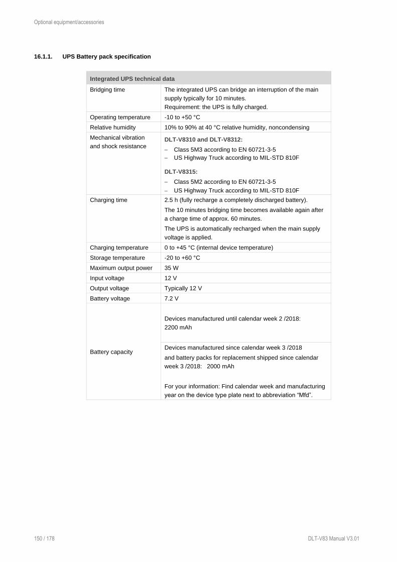
Optional equipment/accessories
150 / 178 DLT-V83 Manual V3.01
16.1.1. UPS Battery pack specification
Integrated UPS technical data
Bridging time The integrated UPS can bridge an interruption of the main
supply typically for 10 minutes.
Requirement: the UPS is fully charged.
Operating temperature -10 to +50 °C
Relative humidity 10% to 90% at 40 °C relative humidity, noncondensing
Mechanical vibration
and shock resistance DLT-V8310 and DLT-V8312:
− Class 5M3 according to EN 60721-3-5
− US Highway Truck according to MIL-STD 810F
DLT-V8315:
− Class 5M2 according to EN 60721-3-5
− US Highway Truck according to MIL-STD 810F
Charging time 2.5 h (fully recharge a completely discharged battery).
The 10 minutes bridging time becomes available again after
a charge time of approx. 60 minutes.
The UPS is automatically recharged when the main supply
voltage is applied.
Charging temperature 0 to +45 °C (internal device temperature)
Storage temperature -20 to +60 °C
Maximum output power 35 W
Input voltage 12 V
Output voltage Typically 12 V
Battery voltage 7.2 V
Battery capacity
Devices manufactured until calendar week 2 /2018:
2200 mAh
Devices manufactured since calendar week 3 /2018
and battery packs for replacement shipped since calendar
week 3 /2018: 2000 mAh
For your information: Find calendar week and manufacturing
year on the device type plate next to abbreviation “Mfd”.

Optional equipment/accessories
DLT-V83 Manual V3.00 151 / 178
16.1.2. Charging the integrated UPS correctly
To charge the battery packs of the integrated UPS:
Connect the properly installed DLT-V83 to the main supply voltage.
NOTICE: The cable cover of the DLT-V83 must be screwed together properly; the device must be
fully closed.
Charging time: 2.5 hours (fully recharge a completely discharged battery).
Do not remove the battery packs from the cable cover; do not charge with external chargers.
Do not connect damaged cable covers with battery packs to the DLT-V83; do not charge.
Battery packs become warm while charging; this is normal. However, if they become excessively
hot, immediately disconnect the DLT-V83 from the power source.
Do not continue to use the DLT-V83 if you notice an unusual level of heat or an unusual smell
during charging.
Provide for sufficient ventilation of the DLT-V83 when charging the battery packs.
16.1.3. No repair/replacement of the battery packs
If the battery packs are faulty, the entire cable cover, including the integrated battery packs, must be
replaced.
16.2. Screen-Defroster (optional)
Some DLT-V83 device models are available optionally with a Screen-Defroster.
Functional description
As soon as the internal temperature of the DLT-V83 device falls below 0 °C, the Screen-Defroster is
automatically activated and heats the front of the device.
The front of the device thus thaws more quickly when leaving cold stores, for example.
In terms of the ambient temperature, this means:
− The Screen-Defroster is typically activated at an ambient temperature of -5 to -15 °C.
This depends on how quickly the ambient temperature changes or how quickly the DLT-V83 cools.
− The Screen-Defroster is typically deactivated again when the ambient temperature rises up to +5 to
+15 °C.
The Screen-Defroster has a heat output of approx. 20 watts.
NOTICE: Property damage
When using DLT-V83 devices with a Screen-Defroster and UPS:
Do not park or store vehicles on which DLT-V83 devices with a Screen-Defroster and an
integrated UPS are installed in areas with ambient temperatures below 0 °C.
If vehicles on which DLT-V83 devices with a Screen-Defroster and an integrated UPS are
installed are parked or stored for a significant length of time, disconnect the DLT-V83 from
the vehicle battery.

Optional equipment/accessories
152 / 178 DLT-V83 Manual V3.01
16.3. Pre-converter and power cables (optional)
Available for all DLT-V83 devices with DC power supply unit:
− Preconverter
− DC power cable
Available for the DLT-V8315 with AC power supply unit:
− AC Power cables EU and US
16.4. Voice Kit (optional)
The optional Voice Kit of the DLT-V83 contains a handheld microphone including speaker and bracket.
The internal speaker of the DLT-V83 is automatically deactivated if the Voice Kit is connected.
The handheld microphone is connected to the Audio/Mic interface of the DLT-V83.
Please use only handsets from “OTTO Communications”. Please contact your Advantech sales
representative if needed.
Fig. 16.2: Voice Kit microphone (optional)
Voice Kit configuration under MS-Windows
To configure the voice kit, use the Control Panel menu Audio Settings. In the expanded view, the
internal speaker can be configured as well as the external handset speaker (Expansion) and the
microphone.
With the Mute button it is possible to activate/deactivate the speaker and the microphone individually.
The option Route Micro to Output can be used for testing and sends the microphone signal directly to
the speaker.
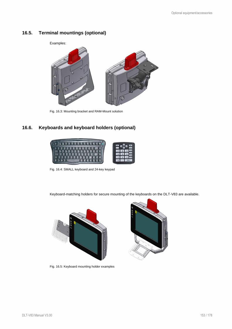
Optional equipment/accessories
DLT-V83 Manual V3.00 153 / 178
16.5. Terminal mountings (optional)
Examples:
Fig. 16.3: Mounting bracket and RAM-Mount solution
16.6. Keyboards and keyboard holders (optional)
Fig. 16.4: SMALL keyboard and 24-key keypad
Keyboard-matching holders for secure mounting of the keyboards on the DLT-V83 are available.
Fig. 16.5: Keyboard mounting holder examples
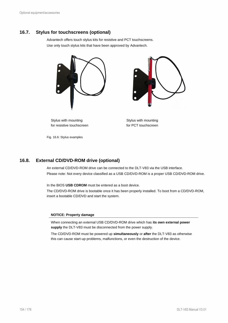
Optional equipment/accessories
154 / 178 DLT-V83 Manual V3.01
16.7. Stylus for touchscreens (optional)
Advantech offers touch stylus kits for resistive and PCT touchscreens.
Use only touch stylus kits that have been approved by Advantech.
Stylus with mounting
for resistive touchscreen
Stylus with mounting
for PCT touchscreen
Fig. 16.6: Stylus examples
16.8. External CD/DVD-ROM drive (optional)
An external CD/DVD-ROM drive can be connected to the DLT-V83 via the USB interface.
Please note: Not every device classified as a USB CD/DVD-ROM is a proper USB CD/DVD-ROM drive.
In the BIOS USB CDROM must be entered as a boot device.
The CD/DVD-ROM drive is bootable once it has been properly installed. To boot from a CD/DVD-ROM,
insert a bootable CD/DVD and start the system.
NOTICE: Property damage
When connecting an external USB CD/DVD-ROM drive which has its own external power
supply the DLT-V83 must be disconnected from the power supply.
The CD/DVD-ROM must be powered up simultaneously or after the DLT-V83 as otherwise
this can cause start-up problems, malfunctions, or even the destruction of the device.

Optional equipment/accessories
DLT-V83 Manual V3.00 155 / 178
16.9. USB recovery stick (optional)
The optional Advantech recovery stick allows images to be backed up and restored onto the DLT-V83
when necessary (backup & recovery).
16.10. Scanner and scanner bracket (optional)
You can connect scanners to either the USB interface or the serial interface. If connected to COM1, the
scanner can be powered through the interface with a voltage of 5 V or 12 V (option).
Use only scanners that have been approved by Advantech.
Optional scanner brackets are available for the DLT-V83.
16.11. Sun visor (optional)
Fig. 16.7: DLT-V8312 with sun visor
Technical data
Material Aluminum, powder coated
Weight of sun visor DLT-V8310 300 g
Weight of sun visor DLT-V8312 357 g
Screws DIN912 M6x10 A2 TufLok
Washers DIN 1440-A6-A2
Tightening torque 10 Nm
16.12. Protective film for touchscreen (optional)
An optional protective film is available for resistive touchscreens. This film protects the touchscreen
during extreme use.

Maintenance, Cleaning
156 / 178 DLT-V83 Manual V3.01
17. Maintenance, Cleaning
17.1. Manufacturer, authorized service centers
WARNING
Only the manufacturer and its authorized service centers may perform:
− Repairs
− Modifications
− Replace modules
− Open the device
The legal warranty shall apply. It expires if the customer performs measures on the device that
are only permitted to be performed by the manufacturer and its authorized Service Centers.
17.2. No repair/replacement of the battery packs
If the battery packs are faulty, the entire cable cover, including the integrated battery packs, must be
replaced.
17.3. Regular checks and maintenance of the complete system
If the attachment of the DLT-V83 becomes loose and breaks during driving, this can lead to severe
accidents.
To ensure the stability and security of the DLT-V83 complete system:
Regularly check whether the DLT-V83 is firmly seated in the associated holder (RAM mount,
mounting bracket) and the mounting screws are not loose.
Also check whether the bracket is secured firmly to vehicle.
Check whether all connected cables are secured and the cable cover shuts tightly.
A regular inspection and maintenance of the entire system is necessary.

Maintenance, Cleaning
DLT-V83 Manual V3.00 157 / 178
17.4. Cleaning the device
WARNING
Hazardous voltage, electric shock from contact with live parts when cleaning the device.
To prevent an electric shock:
Switch off the DLT-V83 before cleaning.
Disconnect from the power supply.
Disconnect connected accessories.
NOTICE: Property damage
Cleaning touchscreen and housing.
Never use chemical solvents to clean the touchscreen.
Do not use acidic or alkaline solutions.
Do not use cleaning agents that contain ammonia or sulfur (tile cleaners, for example,
contain ammonia).
Do not use any abrasive glass cleaner or cloths that could scratch the touchscreen.
Do not use compressed air, a high-pressure cleaner or vacuum cleaner, as this can
damage the surface.
Using a high-pressure cleaner poses the additional risk of water entering the device and
damaging the electronics or display.
17.4.1. Cleaning the housing
Ensure that the device is switched off and currentless.
Clean the housing with a damp cloth.
17.4.2. Cleaning the touchscreen
Device with PCT touchscreen: Switch off the device completely.
Device with resistive touchscreen: Deactivate the touchscreen:
Use a neutral glass cleaner (without ammonia, without isopropyl alcohol)
applied to a lint-free cloth.
NOTICE: Do not apply cleaning agent to the touchscreen; apply it to the cleaning cloth.
Then wipe off the touchscreen with it.
Then use distilled water to remove any residual cleaner.

Maintenance, Cleaning
158 / 178 DLT-V83 Manual V3.01
17.5. Touchscreen protective film (optional)
NOTICE: Property damage
Do not attach the protective film to damaged or worn out touchscreens. Air bubbles can get
trapped and cause malfunctions.
The ordered optional protective film is normally attached to the DLT-V83 touchscreen at the factory.
If the film must be attached by the customer or replaced:
Turn off the DLT-V83.
Use a neutral glass cleaner without ammonia or isopropyl alcohol applied to a lint-free cloth.
Wipe off the touchscreen with it.
Then use distilled water to remove any residual glass cleaner.
NOTICE: Property damage
Never use any kind of chemical solvent, acidic or alkali solution.
Do not use any abrasive glass cleaner or cloths that could scratch the touchscreen.
Make sure that the surface of the touchscreen is free of dust and other particles.
Position the protective film with the adhesive side facing downwards tight at one corner of the
viewing window.
Carefully press on the foil.
Then using a wiper (wooden wiper) to push out any air bubbles to the corners.

Malfunctions
DLT-V83 Manual V3.00 159 / 178
18. Malfunctions
Error Possible cause(s) Remedy
Device does not boot Are all plug connections connected
correctly?
Is the <Power> button / Ign
configuration correct?
Correct voltage ranges present?
Mouse pointer
position and
touchscreen touch
position do not
match
If the deviation is large, recalibrate the
touchscreen.
AC devices: signal
transmission
problems with
connected devices
External electrical isolation of the
relevant lines recommended.
Battery pack run
time is significantly
shorter than
specified.
The device may possibly
not be in the temperature
range which is necessary
for charging the battery
pack.
Check the temperature specifications
for the device and surroundings.
Maximum number of
charging cycles of the
battery pack has been
reached.
If temperature causes can be ruled out,
the battery pack has possibly reached
the maximum number of charging
cycles.
Replace the battery pack. Use only
original battery pack from Advantech.
No UPS functionality
although battery
pack is plugged in.
Battery pack is discharged
or deep discharged.
Charge the battery pack properly.
Observe: If the battery pack is deep
discharged, the charging time can
increase by a multiple.
Nothing is shown on
the display,
Power LED does not
light up.
There is no voltage
present on the device.
Check the power switch, plug
connection, power supply cable and
fuse.
Ignition signal missing. Check ignition cable and signal
Nothing is shown on
the display, Power
LED active.
Backlight is switched off. Press backlight key ("light bulb"
symbol).
Brightness to low Increase display brightness with key
Nothing is shown on
the display,
Temp LED active.
Operating temperature
limits
exceeded/undershot .
Wait until the device has cooled down
resp. warmed up.
Touchscreen reacts
imprecisely.
Touchscreen is switched
off.
Press touchscreen on/off.
Touch driver error Reinstall the touch driver or change
settings

Malfunctions
160 / 178 DLT-V83 Manual V3.01
Device cannot be
operated by touch
input
Touchscreen is not
calibrated correctly.
The touchscreens is already calibrated
at the factory and therefore and does
usually not need to be recalibrated.
However, the operating systems MS
Windows 7 Pro, Windows 8.1 Industry
and WE8S do permit recalibration of
the touchscreen via software (Menu
Control Panel -> Tablet PC Settings).
This resets the sensitivity of the
touchscreen to an operating system
default setting, which can result in
poorer detection of taps on the screen.
You can use Reset to reset the
software recalibration.
Operating system
does not start
External boot media lock Remove all external storage
Operating system damage Operating system or image must be
reinstalled
Software keyboard
not functioning
License missing or invalid Enter the correct software license
No WLAN
connection
Connection deactivated Activate connection in the Control
Panel
AP access problem List ACL and check access rights to AP
Invalid network settings Check WLAN, authorization
parameters, network and protocol
settings
Signal strength too weak Check signal strength and quality in
software; if necessary, the network
must be enlarged
The system looses
settings after a
restart
Write protection activated Deactivate write protection or authorize
changes in operating system
Operating system damage Operating system or image must be
reinstalled
No network
connection
Connection deactivated Activate connection in the Control
Panel
Invalid network settings Check network and protocol settings
Network problems Check status LEDs on RJ45
connection socket, plug connection
and cable

Reasonably foreseeable misuse
DLT-V83 Manual V3.00 161 / 178
19. Reasonably foreseeable misuse
19.1. General
− Observe the permissible environmental conditions
− Observe correct voltage ranges.
19.2. Mobile application on vehicles
− Ensure that supply lines are fused correctly.
− Read the labeling on the cable and connect the power supply cable with the correct polarity.
− Cut the power supply cable as short as possible. This avoids tangled cables and improves the quality
of the power supply.
− Observe the vehicle manufacturer’s instructions for connecting additional loads, for instance, in
conjunction with an emergency shut-off switch.
− Be sure that the connection of the line is as directly as possible to the battery and not to power
supply lines with a great deal of interference (e.g. the engine power supply) or otherwise affected by
consumers.
− Connect the power supply cable to a suitable place. Ensure that the connecting cable has an
adequate cross section and ampacity at the connection point.
19.3. Stationary use with AC power supply unit
Please observe that the switch of the Advantech power supply cable must be set to On in order to be
able to start the DLT-V83.

Guidelines and certificates
162 / 178 DLT-V83 Manual V3.01
20. Guidelines and certificates
20.1. Simplified EU declaration of conformity
The manufacturer:
Advantech Co., Ltd.
NO.1, Alley 20, Lane 26, Rueiguang Road, Neihu District, Taipei 114, Taiwan (R.O.C.)
Authorized representative in Europe:
Advantech Europe B.V.
Science Park Eindhoven 5708, 5692 ER Son, Netherlands
Hereby declares that the following products
Product name: Industrial Computer
Model name: DLT-V83xx
Comply with the provisions of the applicable EU directives, including their amendments applicable at the
time of the declaration. For getting the detailed declarations of conformity please visit
www.advantech.com or www.advantech.eu and contact your regional person in charge.
20.2. Low-voltage guidelines
DLT-V83 devices were tested and fulfill the IEC60950-1.
20.3. EMC guidelines
20.3.1. Shielded components
All components connected to the DLT-V83, as well as cable connections must also meet the legal EMC
requirements for compliance with the EMC legislation. For this reason, screened bus, LAN cables and
connectors must be used.
20.3.2. EMC EU
DLT-V83 devices fulfill the requirements of the EU Directive "2014/30/EU Electromagnetic
Compatibility".
20.3.3. FCC USA
Original wording of the Federal Communications Commission
This equipment has been tested and found to comply with the limits for a Class B digital device,
pursuant to part 15 of the FCC Rules.
These limits are designed to provide reasonable protection against harmful interference in a residential
installation.
This equipment generates, uses and can radiate radio frequency energy and, if not installed and used in
accordance with the instructions, may cause harmful interference to radio communications. However,
there is no guarantee that interference will not occur in a particular installation. If this equipment does
Guidelines and certificates
DLT-V83 Manual V3.00 163 / 178
cause harmful interference to radio or television reception, which can be determined by turning the
equipment off and on, the user is encouraged to try to correct the interference by one or more of the
following measures:
Reorient or relocate the receiving antenna.
Increase the separation between the equipment and receiver.
Connect the equipment into an outlet on a circuit different from that to which the receiver is
connected.
Consult the dealer or an experienced radio/TV technician for help.
CAUTION
Radio frequency exposure.
In order to comply with the FCC requirements regarding radio frequency exposure from
vehicle-mounted transmission devices:
The antenna has to be kept at least 20 cm away from people.
Any change or modification which is not expressly approved in the corresponding pages can
lead to the withdrawal of the operating license for this device.
FCC ID
Please find the FCC ID on the device lables.
20.3.4. ICES Canada
English: This Class A digital apparatus complies with Canadian ICES-003.
Français
[French]:
Cet appareil numérique de la classe A est conforme à la norme NMB-003
du Canada.
IC ID
Please find the IC ID on the device lables.
20.4. RoHS Directive EU
We hereby confirm the conformity of our products compliant with the RoHS Directive 2011/65/EU of the
European Parliament and Council of June 8, 2011 on the restriction of the use of hazardous substances
in electrical and electronic equipment.

Guidelines and certificates
164 / 178 DLT-V83 Manual V3.01
20.5. RED (Radio Equipment Directive) 2014/53/EU
With regard to the RED (Radio Equipment Directive) 2014/53/EU the statements in the declaration of
conformity for the DLT-V83 Industrial Computer apply.
Česky [Czech]: Toto zařízení je v souladu se základními požadavky a ostatními
odpovídajícími ustanoveními Směrnice 2014/53/EU.
Dansk [Danish]: Dette udstyr er i overensstemmelse med de væsentlige krav og andre
relevante bestemmelser i Direktiv 2014/53/EU.
Deutsch
[German]:
Dieses Gerät entspricht den grundlegenden Anforderungen und den
weiteren entsprechenden Vorgaben der Richtlinie 2014/53/EU.
Eesti
[Estonian]:
See seade vastab direktiivi 2014/53/EU (EÜ) olulistele nõuetele ja teistele
asjakohastele sätetele.
English: This equipment is in compliance with the essential requirements and other
relevant provisions of Directive 2014/53/EU.
Español
[Spanish]:
Este equipo cumple con los requisitos esenciales asi como con otras
disposiciones de la Directiva 2014/53/EU (CE).
Ελληνική
[Greek]:
Αυτός ο εξοπλισµός είναι σε συµµόρφωση µε τις ουσιώδεις απαιτήσεις και
άλλες σχετικές διατάξεις της Οδηγίας 2014/53/EU.
Français
[French]:
Cet appareil est conforme aux exigences essentielles et aux autres
dispositions pertinentes de la Directive 2014/53/EU.
Íslenska
[Icelandic]:
Þetta tæki er samkvæmt grunnkröfum og öðrum viðeigandi ákvæðum
Tilskipunar 2014/53/EU.
Italiano
[Italian]:
Questo apparato é conforme ai requisiti essenziali ed agli altri principi
sanciti dalla Direttiva 2014/53/EU (CE).
Latviski
[Latvian]:
Šī iekārta atbilst Direktīvas 2014/53/EU (EK) būtiskajām prasībām un
citiem ar to saistītajiem noteikumiem.
Lietuvių
[Lithuanian]:
Šis įrenginys tenkina 2014/53/EU (EB) Direktyvos esminius reikalavimus ir
kitas šios direktyvos nuostatas.
Nederlands
[Dutch]:
Dit apparaat voldoet aan de essentiele eisen en andere van toepassing
zijnde bepalingen van de Richtlijn 2014/53/EU.
Malti
[Maltese]:
Dan l-apparat huwa konformi mal-ħtiġiet essenzjali u l-provedimenti l-oħra
rilevanti tad-Direttiva 2014/53/EU.
Magyar
[Hungarian]:
Ez a készülék teljesíti az alapvető követelményeket és más 2014/53/EU
(EK) irányelvben meghatározott vonatkozó rendelkezéseket.
Norsk
Norwegian]:
Dette utstyret er i samsvar med de grunnleggende krav og andre relevante
bestemmelser i EU-direktiv 2014/53/EU (EF).
Polski
[Polish]:
Urządzenie jest zgodne z ogólnymi wymaganiami oraz szczególnymi
warunkami określonymi Dyrektywą UE: 2014/53/EU.
Português
[Portuguese]:
Este equipamento está em conformidade com os requisitos essenciais e
outras provisões relevantes da Directiva 2014/53/EU.
Slovensko
[Slovenian]:
Ta naprava je skladna z bistvenimi zahtevami in ostalimi relevantnimi
pogoji Direktive 2014/53/EU.
Slovensky
[Slovak]:
Toto zariadenie je v zhode so základnými požiadavkami a inými
príslušnými nariadeniami direktív: 2014/53/EU.
Suomi
[Finnish]:
Tämä laite täyttää direktiivin 2014/53/EU (EY) olennaiset vaatimukset ja on
siinä asetettujen muiden laitetta koskevien määräysten mukainen.
Svenska
[Swedish]:
Denna utrustning är i överensstämmelse med de väsentliga kraven och
andra relevanta bestämmelser i Direktiv 2014/53/EU.
Guidelines and certificates
DLT-V83 Manual V3.00 165 / 178
WLAN special regulations for Germany and France
For the DLT-V83 with WLAN 802.11a/b/g/n, the following restrictions apply:
− In Germany, WLAN 5 GHz band: 5.15 GHz – 5.35 GHz may only be used indoors.
− In France, WLAN operation outdoors is only permitted in the 2454 – 2483.5 MHz range at max.
10 mW EIRP.
20.6. Eco-design directive (2009/125/EC)
DLT-V83 Industrial Computers with an AC power supply unit meet the requirements of the Eco-design
directive (2009/125/EC), which prescribes environmentally friendly design for products involved in
energy consumption.
20.7. CE marking
The devices of the DLT-V83 series were tested and fulfill the CE conformity requirements and carry the
CE mark on the rear side of the device.
20.8. CCC, SRRC China
Several DLT-V83 models are CCC- and SRRC-certified and carry the respective mark on the device
label.
NOTICE
声明:此为A级产品,在生活环境中,该产品可能会造成无线电干扰,
在这种情况下,可能需要用户对其干扰采取切实可行的措施。

Guidelines and certificates
166 / 178 DLT-V83 Manual V3.01
20.9. CNROHS
20.10. MIC Japan (previously TELEC)
In several DLT-V83 models, the PE15N PCI Express Mini Card from Laird is used. Laird has
implemented the following MIC certifications for this:
− Article 2 Item 19, Category WW (2.4 GHz Channels 1 - 13)
− Article 2 Item 19-2, Category GZ (2.4 GHz Chanel 14)
− Article 2 Item 19-2, Category XW (5150-5250 W52 & 5250-5350 W53)
− Article 2 Item 19-2, Category YW (5470-5725 W56)
Source:
http://www.lairdtech.com/Products/Embedded-Wireless-Solutions/Summit-WLAN-Radio-
Modules/Device-Certification-Guide/#MIC

Recycling information
DLT-V83 Manual V3.00 167 / 178
21. Recycling information
Used DLT-V83 devices, battery packs and batteries
that are no longer being used may not be disposed of
in the regular residential or domestic waste; they
must be taken to an official public collection point and
handled by a disposal provider.
Please contact the responsible authorities in your
country/region to find out about the applicable
regulations for proper disposal, if necessary.

List of figures
168 / 178 DLT-V83 Manual V3.01
22. List of figures
Fig. 5.1: Dimensions DLT-V8310 ........................................................................................................................................ 17 Fig. 5.2: Dimensions DLT-V8312 ........................................................................................................................................ 18 Fig. 5.3: Dimensions DLT-V8315 ........................................................................................................................................ 19 Fig. 5.4: Internal speaker position ....................................................................................................................................... 20 Fig. 5.5: DC power supply connector with connector detail view ......................................................................................... 21 Fig. 5.6: DC connection cable, original Advantech .............................................................................................................. 23 Fig. 5.7: DC connection cable assignment - drawing .......................................................................................................... 23 Fig. 5.8: AC power connector with detail view ..................................................................................................................... 24 Fig. 6.1: WLAN antenna IEEE 802.11 a/b/g/n and antenna module (optional) .................................................................... 30 Fig. 6.2: WLAN antenna IEEE 802.11 a/b/g/n/ac and antenna module (optional) ............................................................... 31 Fig. 6.3: WLAN, WWAN 3G antenna (optional) ................................................................................................................... 32 Fig. 6.4: DLT-V83 rear view with WLAN, WWAN, LTE 4G antenna (Multiband) ................................................................. 33 Fig. 6.5: External WLAN antenna (optional) ........................................................................................................................ 34 Fig. 6.6: External 3G WWAN antenna (optional) ................................................................................................................. 35 Fig. 6.7: External WWAN antenna (optional) ....................................................................................................................... 36 Fig. 6.8: External GPS receiver (optional) ........................................................................................................................... 38 Fig. 6.9: Ext. GPS receiver, display example during installation .......................................................................................... 38 Fig. 7.1: RJ45 network port ................................................................................................................................................. 41 Fig. 7.2: CAN, Digital In/Out and second Ethernet interface ................................................................................................ 42 Fig. 7.3: Pin assignment of CAN interface ........................................................................................................................... 42 Fig. 7.4: Digital I/O interface pin position ............................................................................................................................. 43 Fig. 7.5: Optional RJ45 network socket of the DLT-V83 ...................................................................................................... 44 Fig. 7.6: DC device external connections with optional expansion interfaces ...................................................................... 45 Fig. 7.7: AC device external connections with optional expansion interfaces ...................................................................... 46 Fig. 7.8: Example of antenna, type 4 in 1 ............................................................................................................................ 47 Fig. 7.9: Protective cap examples ....................................................................................................................................... 47 Fig. 8.1: WLAN antenna unscrewed .................................................................................................................................... 49 Fig. 8.2: Open WLAN antenna IEEE 802.11 a/b/g/n/ac ....................................................................................................... 50 Fig. 8.3: WLAN antenna IEEE 802.11 a/b/g/n/ac opened.................................................................................................... 50 Fig. 8.4: WLAN, WWAN 3G antenna ................................................................................................................................... 51 Fig. 8.5: WLAN, WWAN 3G antenna opened ...................................................................................................................... 51 Fig. 8.6: Open WLAN, WWAN antenna ............................................................................................................................... 52 Fig. 8.7: Open WLAN / WWAN antenna .............................................................................................................................. 52 Fig. 8.8: WLAN, WWAN antenna opened............................................................................................................................ 52 Fig. 9.1: <Power> button ..................................................................................................................................................... 56 Fig. 9.2: Example: DLT-V8312 version with 26 front keys ................................................................................................... 58 Fig. 9.3: Example: Operating elements front side DLT-V8310 with PCT touchscreen ........................................................ 63 Fig. 9.4: Software keyboard example .................................................................................................................................. 65 Fig. 10.1: DLoG Config Tool main menu, example Win 10 IoT Enterprise .......................................................................... 68 Fig. 10.2: Start of the IXXAT driver installation .................................................................................................................... 70 Fig. 10.3: iManager: GPIO Bank Control ............................................................................................................................. 71 Fig. 10.4: Network Connection Properties, Advanced ......................................................................................................... 73 Fig 10.5: iManager: Network Connection Properties, Power Management ......................................................................... 73 Fig. 10.6: Network Connection Properties, Advanced ......................................................................................................... 74 Fig 10.7: iManager: Network Connection Properties, Power Management ......................................................................... 74 Fig. 10.8: Network Connection Properties, Advanced ......................................................................................................... 74 Fig.11.1: Setup.exe for 64 bit operating system Win10IoTEnt (Sparklan WLAN) ................................................................ 80 Fig.11.2: Setup.exe Choose Setup Language (Sparklan WLAN) ........................................................................................ 81 Fig.11.3: Sparklan WLAN driver installation Welcome dialog .............................................................................................. 81 Fig.11.4: Sparklan WLAN driver installation starts .............................................................................................................. 82 Fig.11.5: Sparklan WLAN driver installation Exit with Finish ............................................................................................... 82 Fig.11.6: Device Manager network adapter Properties (Qualcomm) ................................................................................... 83 Fig.11.7: Advanced – Roaming aggressiveness Property ................................................................................................... 84 Fig.11.8: Setup.exe for 64 bit operating system Win10IoTEnt (Sparklan BT) ...................................................................... 86 Fig.11.9: Sparklan WLAN driver installation Welcome dialog .............................................................................................. 87

List of figures
DLT-V83 Manual V3.00 169 / 178
Fig.11.10: Sparklan BT driver installation destination folder................................................................................................ 87 Fig.11.11: Sparklan BT driver installation starts .................................................................................................................. 88 Fig.11.12: Sparklan BT driver installation Exit with Finish ................................................................................................... 88 Fig.11.13: Sparklan BT driver installation perform system restart ....................................................................................... 89 Fig.11.14: WCU icon on the desktop ................................................................................................................................... 92 Fig.11.15: WCU main window, Admin Login ....................................................................................................................... 93 Fig.11.16: WCU-Administrator login window ....................................................................................................................... 94 Fig.11.17: Speed buttons for managing profiles .................................................................................................................. 94 Fig.11.18: Check License .................................................................................................................................................... 95 Fig.11.19: Info display via existing license .......................................................................................................................... 95 Fig.11.20: Browse nearby wireless networks function ......................................................................................................... 96 Fig.11.21: Advanced Security Settings dialog ..................................................................................................................... 97 Fig.11.22: Connection when the network is in range dialog ................................................................................................ 97 Fig.11.23: Security settings - network authentication methods ........................................................................................... 98 Fig.11.24: Security settings – Advanced settings (Cisco: Leap) .......................................................................................... 99 Fig.11.25: Security settings – LEAP properties ................................................................................................................... 99 Fig.11.26: Wireless Network properties dialog .................................................................................................................. 100 Fig.11.27: Create new profile dialog .................................................................................................................................. 101 Fig.11.28: Network connection is established ................................................................................................................... 102 Fig.11.29: General dialog in the Roam Management menu .............................................................................................. 103 Fig.11.30: Roaming dialog in the Roam Management menu ............................................................................................ 104 Fig.11.31: Roam Management – Choose Band and Channels ......................................................................................... 105 Fig.11.32: Radio dialog in the Roam Management menu ................................................................................................. 107 Fig.11.33: Adapter Tab in Roam Management menu ....................................................................................................... 108 Fig.11.34: Import/Export feature ........................................................................................................................................ 109 Fig.11.35: Import/Export dialog ......................................................................................................................................... 110 Fig.11.36: Export Profiles to create an „OutputFile.txt“ ..................................................................................................... 110 Fig.11.37: Info box Profiles exported ................................................................................................................................. 111 Fig.11.38: Import process - select an existing “OutputFile.txt” .......................................................................................... 111 Fig.11.39: Info box Profiles exported ................................................................................................................................. 111 Fig.11.40: Record files ...................................................................................................................................................... 112 Fig.11.41: Record files ...................................................................................................................................................... 113 Fig. 11.42: Initial Laird Connection Manager dialog box ................................................................................................... 114 Fig. 11.43: LCM Configuration tab with the Manage Profiles button ................................................................................. 114 Fig. 11.44: LCM Manage Profiles dialog box with the Admin Login tab ............................................................................ 114 Fig. 11.45: Entering the LCM password: SUMMIT ............................................................................................................ 115 Fig. 12.1: SIERRA WIRELESS MC80 - Device manager, Sierra Wireless HSPA Modem ................................................ 119 Fig. 12.2: SIERRA WIRELESS MC80 - Sierra Wireless HSPA Modem - Properties ........................................................ 119 Fig. 12.3: SIERRA WIRELESS MC80 - Set up a new connection or network ................................................................... 119 Fig. 12.4: SIERRA WIRELESS MC80 - Connect to the Internet ....................................................................................... 120 Fig. 12.5: SIERRA WIRELESS MC80 - Connect to the Internet - Dial-up ......................................................................... 120 Fig. 12.6: SIERRA WIRELESS MC80 - Telephone number and connection name ........................................................... 120 Fig. 12.7: SIERRA WIRELESS MC80 - Network connections - Vodafone test connection ............................................... 121 Fig. 12.8: SIERRA WIRELESS MC80 – Dial test connection ............................................................................................ 121 Fig. 12.9: SIERRA WIRELESS MC80 - Function test GSM / GNSS, test connection status............................................. 121 Fig. 12.10: SIERRA WIRELESS MC80 - Virtual COM ports DLT-V83 with D525 processor ............................................ 122 Fig. 12.11: SIERRA WIRELESS MC80 - Virtual COM ports DLT-V83 with i5 processor .................................................. 123 Fig. 12.12: SIERRA WIRELESS MC80 - Virtual COM ports DLT-V83 with Celeron processor......................................... 123 Fig. 12.13: SIERRA WIRELESS MC80 - test NMEA data flows ........................................................................................ 124 Fig. 12.14: QUECTEL EC25 - Set up a new connection or network ................................................................................. 125 Fig. 12.15: QUECTEL EC25 - Connect to the Internet ...................................................................................................... 125 Fig. 12.16: QUECTEL EC25 - Connect to the Internet - Dial-up ....................................................................................... 126 Fig. 12.17: QUECTEL EC25 - Connect to the Internet - Telephone number ..................................................................... 126 Fig. 12.18: QUECTEL EC25 - Network connections - Vodafone test connection.............................................................. 126 Fig. 12.19: QUECTEL EC25 - Dial Vodafone test connection ........................................................................................... 127 Fig. 12.20: QUECTEL EC25 - Function test GSM / GNSS, test connection status ........................................................... 127 Fig. 12.21: QUECTEL EC25 - Virtual COM ports DLT-V83 with i5 processor ................................................................... 128

List of figures
170 / 178 DLT-V83 Manual V3.01
Fig. 12.22: QUECTEL EC25 - Virtual COM ports DLT-V83 with Celeron processor ......................................................... 129 Fig. 12.23: QUECTEL EC25 - Test NMEA data flows ...................................................................................................... 130 Fig. 13.1: Position of the VESA drill holes DLT-V8310 ...................................................................................................... 134 Fig. 13.2: Position of the VESA drill holes DLT-V8312 ...................................................................................................... 135 Fig. 13.3: Position of the VESA drill holes DLT-V8315 ...................................................................................................... 136 Fig. 14.1: DC connection cable with Phoenix contact connector ....................................................................................... 138 Fig. 14.2: Position of the ground bolt ................................................................................................................................. 139 Fig. 15.1: Cable cover with integrated UPS battery (optional) ........................................................................................... 143 Fig. 15.2: Dummy grommets and cable grommets for various cable diameters ................................................................ 143 Fig 15.3: Cable grommets and dummy grommets ............................................................................................................. 144 Fig. 15.4: Example cable grommet .................................................................................................................................... 145 Fig. 15.5: The power supply cable, fit with a cable grommet, in the strain relief rail .......................................................... 145 Fig. 15.6: Unused cable outlets sealed off......................................................................................................................... 145 Fig. 15.7: Power supply cable with cable clip on the strain relief rail ................................................................................. 146 Fig. 15.8: Detailed view cable clips on strain relief rail ...................................................................................................... 146 Fig. 15.9: Cables and dummy grommets ........................................................................................................................... 146 Fig. 15.10: Screwing the cable cover into place ................................................................................................................ 147 Fig. 15.11: Cable cover with integrated UPS battery ......................................................................................................... 147 Fig. 15.12: Pressure compensation element - Do not modify or remove! .......................................................................... 148 Fig. 16.1: Cable cover with integrated battery packs for the UPS ..................................................................................... 149 Fig. 16.2: Voice Kit microphone (optional) ......................................................................................................................... 152 Fig. 16.3: Mounting bracket and RAM-Mount solution ....................................................................................................... 153 Fig. 16.4: SMALL keyboard and 24-key keypad ................................................................................................................ 153 Fig. 16.5: Keyboard mounting holder examples ................................................................................................................ 153 Fig. 16.6: Stylus examples ................................................................................................................................................ 154 Fig. 16.7: DLT-V8312 with sun visor.................................................................................................................................. 155