
dk2250ch15
49
443 15 Nuclear Energy Sudarshan K. Loyalka CONTENTS 15.1 Nuclear Fission and Nuclear Reactor Physics ............................................ 443 15.2 Electricity Generation from Nuclear Reactors ............................................ 451 15.2.1 Reactor Control and a Toy Model ................................................... 455 15.3 Nuclear Fuel Cycle ...................................................................................... 458 15.4 Types of Reactors......................................................................................... 462 15.4.1 Advanced Reactors and Concepts ................................................... 467 15.4.2 Hydrogen Production ....................................................................... 475 15.5 Public Concerns of Safety and Health ........................................................ 475 15.5.1 Nuclear Weapons Proliferation ........................................................ 482 15.5.2 Nuclear Waste Disposal ................................................................... 483 15.5.3 Terrorism .......................................................................................... 484 15.6 Nuclear Fusion ............................................................................................. 484 References .............................................................................................................. 489 15.1 NUCLEAR FISSION AND NUCLEAR REACTOR PHYSICS The neutron was discovered in 1932. The following years witnessed intense studies of its properties and interactions with matter. This neutral particle is about 2000 times the mass of an electron, and is scattered and absorbed by different materials. The nature and rate of its reaction are determined by the nuclei of the host material and the energy of the neutron. Moreover, the nuclei that absorb neutrons can become radioactive and be transmuted to other types of nuclei, through radioactive decays. Neutrons can also split (fission) some nuclei (the fissile isotopes such as U-233, U- 235, and Pu-239). Such fission is a complex process that produces new nuclei, beta and gamma radiation, and a few neutrons themselves. The products are energetic (the kinetic energy of fission products, energy of the radiation), deriving their energy from the binding energy of the nucleus. Consequently, the new neutrons (2 to 3 on average) released in fission provide the basis for a chain reaction. This chain reaction can be sustained (each successive generation has the same number of neutrons) or multiplied (each successive generation has more neutrons), and it can be used for a controlled and a sustained as well as an explosive release of energy. 1–21 © 2007 by Taylor & Francis Group, LLC
-
Upload
damiansalvo -
Category
Documents
-
view
181 -
download
0
Transcript of dk2250ch15

443
15 Nuclear Energy
Sudarshan K. Loyalka
CONTENTS
15.1 Nuclear Fission and Nuclear Reactor Physics ............................................ 44315.2 Electricity Generation from Nuclear Reactors ............................................ 451
15.2.1 Reactor Control and a Toy Model ................................................... 45515.3 Nuclear Fuel Cycle ...................................................................................... 45815.4 Types of Reactors......................................................................................... 462
15.4.1 Advanced Reactors and Concepts ................................................... 46715.4.2 Hydrogen Production ....................................................................... 475
15.5 Public Concerns of Safety and Health ........................................................ 47515.5.1 Nuclear Weapons Proliferation ........................................................ 48215.5.2 Nuclear Waste Disposal ................................................................... 48315.5.3 Terrorism .......................................................................................... 484
15.6 Nuclear Fusion ............................................................................................. 484References.............................................................................................................. 489
15.1 NUCLEAR FISSION AND NUCLEAR REACTOR PHYSICS
The neutron was discovered in 1932. The following years witnessed intense studiesof its properties and interactions with matter. This neutral particle is about 2000times the mass of an electron, and is scattered and absorbed by different materials.The nature and rate of its reaction are determined by the nuclei of the host materialand the energy of the neutron. Moreover, the nuclei that absorb neutrons can becomeradioactive and be transmuted to other types of nuclei, through radioactive decays.Neutrons can also split (fission) some nuclei (the fissile isotopes such as U-233, U-235, and Pu-239). Such fission is a complex process that produces new nuclei, betaand gamma radiation, and a few neutrons themselves. The products are energetic(the kinetic energy of fission products, energy of the radiation), deriving their energyfrom the binding energy of the nucleus. Consequently, the new neutrons (2 to 3 onaverage) released in fission provide the basis for a chain reaction. This chain reactioncan be sustained (each successive generation has the same number of neutrons) ormultiplied (each successive generation has more neutrons), and it can be used for acontrolled and a sustained as well as an explosive release of energy.1–21
© 2007 by Taylor & Francis Group, LLC

444 Handbook of Alternative Fuel Technology
Fission of a single nucleus releases about 200 MeV (3.2 10–11 J) of energy. Thisenergy is distributed, in a power reactor of modern design, approximately as shownin Table 15.1 and Figure 15.1.
Of this 200 MeV, about 190 MeV, or 95%, is recoverable energy, as the neutrinosdo not interact with matter, and escape from the system without depositing energy.One kilogram of U-235 contains 2.563 × 1024 U-235 nuclei, and its fission wouldrelease energy of about 78 × 106 MJ (which is the same as 21.6 × 10⁶ kWh or2.47 MWyr).
The fission products and beta and alpha particles are mostly deposited within afraction of centimeter from the point of birth (in a solid or a liquid), whereas neutronsand gammas travel a greater distance depending on their energy and the material.The prompt radiation is emitted within 10–17 to 10–6 sec from an interaction, whereasthe delayed radiation can be emitted within a few milliseconds to thousands of years(e.g., the long-lived isotopes).
The U-235 and neutron fission reaction can thus be described as:
(15.1)
in which A and B can be, for example, nuclei of cesium and strontium, and ν is thenumber of neutrons produced. The reaction is in accordance with generalized laws ofconservation, but A, B, and ν are not necessarily the same for each fission. In fact, a
TABLE 15.1Distribution of Fission Generated Energy in Time and Position
Type Process
Percentof totalreleasedenergy
Principal positionof energy deposition
FissionI: instantaneous energy Kinetic energy of fission fragments 80.5 Fuel material
Kinetic energy of newly born fast neutrons
2.5 Moderator
γ energy released at time of fission 2.5 Fuel and structuresII: delayed energy Kinetic energy of delayed neutrons 0.02 Moderator
β-decay energy of fission products 3.0 Fuel materialsNeutrinos associated with β decay 5.0 Nonrecoverableγ-decay energy of fission products 3.0 Fuel and structures
Neutron captureIII: instantaneous and
delayed energyNonfission reactions due to excess
neutrons plus β- and γ-decay energy of (n, γ) products
3.5 Fuel and structures
Total 100
Source: From El-Wakil, M.M., Nuclear Heat Transport, International Textbook Company, now availablefrom the American Nuclear Society, 1971. With permssion.
U n A B n235 + → + + ν
© 2007 by Taylor & Francis Group, LLC

Nuclear Energy 445
number of species are produced, and both ν and the energy (kinetic) of product neutronsvary. Furthermore, the fission reaction rate is strongly dependent on the energy (kinetic)of the reacting neutron (and also on the kinetic energy of the reacting U-235 in certainenergy ranges). Figure 15.2 and Figure 15.3 show, respectively, the distribution offission products and the distribution in energy of the neutrons produced in fission.
It is useful to note here that in a nuclear reactor the overall neutron density(#/cm3) is smaller than the nuclei density (#/cm3) by about 10 orders of magnitude.Thus, the nuclei distribution is determined by nuclei–nuclei interactions, and theneutron distribution in space, direction, energy, and time is determined by neu-tron–nuclei interaction. In the long term, the fission products, actinides, and latticesuffer damage because the energetic products and neutrons affect the nuclei–nucleiinteractions. Incidentally, both microscopic and macroscopic experiments have been
FIGURE 15.1 Distribution of fission energy in energy and time. (From Ott, K.O. and Neuhold,R.J., Introductory Nuclear Reactor Dynamics, American Nuclear Society, 1985. With permission.)
Fission
FissionFragments
Fast Neutrons
Scattering
PromptFission
Slow Neutrons
Fission Capture
InelasticScattering
Excited Nuclei
Radioactive Nuclei
DelayedNeutrons
Decay Neutrinos Decay
Capture Capture
© 2007 by Taylor & Francis Group, LLC

446 Handbook of Alternative Fuel Technology
used to study neutron–nuclei interactions, and a wealth of information on the natureof these interactions and their rates is now available. The rate Ri(#/sec) for a reactionof type “i” (absorption, fission, scattering) is expressed as:
(15.2)
in which,
FIGURE 15.2 Fission product distribution. (From Weinberg, A.M. and Wigner, E.P., The Phys-ical theory of Neutron Chain Reactors, University of Chicago Press, 1958. With permission.)
76 82 88 94 100 106 112 118 124 130 136 142 148 154 160MASS NUMBER
10
5
2
5
5
1
2
2
5
2
5
2
10-1
10-2
10-3
10-4
U233
U235
Pu239
FIS
SIO
N Y
IELD
(%
)
R E t d d dE E t E t d d dEi ir r r r r, , , , , , , ,Ω Ω Σ Ω Ω( ) = ( ) ( )φ
Σi E t Macroscopicr, ,( ) = cross section (1/lengtth) at at at time
“Ne
r
r
E t
E t dEd
,
, , ,φ Ω Ω( ) = uutron Flux,” (#/area time) at at in dr E E at in at time Ω Ωd t,
© 2007 by Taylor & Francis Group, LLC

Nuclear Energy 447
dr is a volume element at location r, and dΩ is an elemental solid angle in directionΩ. E indicates energy, and t is the time. A neutron balance equation can thus beconstructed as:
(15.3)
This is often known as the Linear Boltzmann Equation for neutron transport, orjust the Transport Equation, as it follows directly from the Nonlinear BoltzmannEquation for molecular distribution in the kinetic theory of gases. Note that v is thespeed of neutrons, the integral includes scattering as well as neutrons born in fission,and S is a source term. Subscript t indicates “total.” The gradient is with respect tor, and the gradient term indicates free streaming or drift. The boundary conditionsfor this equation are usually those of no inward neutron flow for a convex surfacefor a body situated in a vacuum. The initial conditions just prescribe the initial flux.
We should note that the neutron flux is related to the neutron density n by
and that the flux in the nuclear nomenclature is a scalar quantity. Thus,
FIGURE 15.3 Energy distribution of neutrons produced in fission (the fission spectrum).
0 1 2 3 4 5 6 7 8
NEUTRON ENERGY (MeV)
0.4
0.3
0.2
0.1
0
FR
AC
TIO
N O
F F
ISS
ION
NE
UT
RO
NS
PE
R M
eV
1v
E t
tE t E tt
∂ ( )∂
= − ∇ ( ) − ( )φφ φ
rr r r
, , ,. , , , , , ,
ΩΩ Ω Σ EE t
dE d E E t Es
, ,
, , , , , ,
Ω
Ω Σ Ω Ω Ω
( )
+ ′ ′ ′ → ′ →( ) ′ ′∫ ∫ r rφ tt
S E t
( )
+ ( )r, , ,Ω
φ r r, , , , , ,E t vn E tΩ Ω( ) = ( )
φ r r, , ,E t d dE dΩ Ω( )
© 2007 by Taylor & Francis Group, LLC

448 Handbook of Alternative Fuel Technology
should be understood as the path length traveled per unit time by neutrons in theelemental phase space volume . Thus, the inverse of the macroscopic crosssection is the neutron mean free path for that particular reaction, and we have
.Progress of the last few years enables us now to compute the neutron flux for
complicated geometries and reactor configurations by using combinations of ana-lytical, deterministic, and Monte Carlo methods,11–18 and this task has been greatlyaided by advances in computational hardware. In a simplified picture, we note thatfor any given mass, the neutron multiplication factor (the ratio of neutrons in ageneration to the previous generation) can be written as:
(15.4)
and is a measure of the criticality of the mass (k > 1, supercritical; k = 1, critical;k < 1, subcritical. k >= 1 is needed to sustain a chain reaction). The associated rateequation can be written as:
(15.5)
where n(t) is the number density of neutrons (#/cm3), is known as the neutronlifetime (~10–3 to10–6 sec) , and “s” (#/cm3 sec) is a source of neutrons. For a non-re-entrant mass (surface), the factor k is approximately expressed as:
(15.6)
Here, the second term in the denominator relates to the leakage from the system,with rs a point on the surface, and n(rs) a unit normal to the surface directed outwardto vacuum. This term is more important for small assemblies (with respect to theneutron mean free path) and less so for larger assemblies. Small assemblies generallycorrespond to weapons and research reactors, and the larger assemblies to cores ofnuclear power plants. The macroscopic cross section is represented (we suppress theposition dependence) as:
(15.7)
where N, the number density of the nuclei (#/cm3) in the mass, is expressed as:
(15.8)
d dEdr Ω
= ∑1 /
kneutrons produced
neutrons absorbed neutrons=
+ llost due to leakage
dn t
dt= n t +s(t)
k-1( ) ( )
kd dE d E E E
d dE d E
f
a
=( ) ( ) ( )
( )∫∫∫ r r r
r r
Ω Σ Ω
ΩΣ
ν φ, , ,
, φφ φr r r rr
, , . ( ) , ,. ( )
E d dE d n Es s
n s
Ω ΩΩ ΩΩ
( ) + ( )∫∫∫>00
∫∫∫
Σ E N E( ) = ( )σ
NM
= ×0 6023 1024. ρ
© 2007 by Taylor & Francis Group, LLC

Nuclear Energy 449
in which ρ is the density of the mass (gm/cm3), and M is the molecular weight(gm/gmol). σ(cm2) is known as the microscopic cross section for interaction withneutrons. It is different for different processes (fission, absorption, scattering) andgenerally has a complex dependence on the material and the energy. We have showna typical cross section in Figure 15.4 (note, a barn = 10–24 cm2).
For large reactors and design purposes, k can be approximately expressed as:
(15.9)
where an integral on the solid angle is understood. Further, it is convenientlyexpressed as:
where the four factors are defined in Table 15.2.We also define Ec as some cutoff energy (about 1 eV), below which neutrons
are regarded as “thermal” in that they have kinetic energy comparable to those ofthe nuclei, and both gain and lose energy while interacting with nuclei (above thecutoff, the analysis can be simplified by assuming that the neutrons lose energy in
FIGURE 15.4 U-235 total cross section. (ENDFB-VI cross-section files, obtained fromwww.nndc.bnl.gov.)
10-9 10-8 10-7 10-6 10-5 10-4 10-3 10-2 10-110-1
100 101
103
102
101
100
Energy (MeV)
Cro
ss S
ectio
n (b
)
kd dE E E E
d dE E
fall
a
∞
∞
=( ) ( ) ( )
( )∫∫ r r r
r r
ν φ
φ
Σ
Σ
, ,
,
0
rr, Eall
( )∞
∫∫ 0
k fp∞ = εη
© 2007 by Taylor & Francis Group, LLC

450H
and
bo
ok o
f Altern
ative Fuel Tech
no
logy
TABLE 15.2The Four Factors
Factor Approximate Calculation or Measurement
Values (Typical of Natural-Uranium Water)
HomogeneousAssembly
HeterogeneousLattice
Insensitive to geometry. Can be estimated using approximate shapes of the neutron spectrum and cross sections
1.03 1.03
Insensitive to geometry. Can be estimated using , thermal cross sections, and a thermal neutron beam incident on a foil in a manganese bath
1.34 1.34
Assuming
)
R can be measured through use of bare and cadmium-covered gold foils embedded at different points in a typical cell
0.9 0.8
Neutron absorption in thermal and resonance regions can be measured through use of bare and cadmium-covered U-238 foils.
0.7 0.9
εν φ
=∫ ∫∫
∞
( ) ( ) ( )d dE E E E
d dE
fuelf
fuel
Ec
r r r
r
0
0
Σ , ,
∫∫ ( ) ( ) ( )ν φE E EfΣ r r, ,
ην φ
=∫ ∫∫
( ) ( ) ( )d dE E E E
d dE
fuel
E
f
fuel
E
c
r r r
r
0
0
Σ , ,
cc
a E E∫ ( ) ( )Σ r r, ,φ
φ ψr, E EM( ) ( )∼
f
d dE E E
d dE
fuel
E
a
all
E
a
c
c
=∫ ∫∫ ∫
( ) ( )r r r
r r
0
0
Σ
Σ
, ,φ
,, ,E E( ) ( )φ r
φ ψr r, E R EM( ) ( ) ( )∼
p
d dE E E
d dE E
all
E
a
alla
c
=∫ ∫∫ ∫
( ) ( )∞
r r r
r r
0
0
Σ
Σ
, ,
,
φ
(( ) ( )φ r, E
© 2007 by Taylor & Francis Group, LLC

Nuclear Energy 451
collisions, scattering, with nuclei, but do not gain energy). Each of these four factors(known as the fast fission factor, reproduction factor, thermal utilization factor, and theresonance escape probability, respectively) can be experimentally measured or estimated(computed). They aid greatly in understanding the role of various nuclear and materialproperties, thermal conditions, and geometrical arrangements of fuel (UO2, etc.) andmoderators, absorbers, and coolants in influencing k. Use of these four factors was quiteimportant in early design of heterogeneous reactors, and it is still useful today. Forexample, it was found that arrangement of fuel in lumps or lattices leads to a highervalue of k over a homogeneous distribution. Also, whereas a critical reactor cannot beconstructed with just natural uranium (of enrichment currently available) and light watereven in the most favorable geometry, it is possible to construct critical reactors withnatural uranium and graphite or heavy water as moderators, and with a gas, heavy water,or light water as coolants. Indeed, the earliest reactors were constructed with just naturaluranium. We have shown typical values of the four factors in Table 15.2, and notedhow each of these can be measured or calculated approximately.
Clearly, knowledge of the neutron flux is crucial to the design of a reactor asthe criticality and heat generation are directly dependent on it. The flux can becalculated if the geometry and material distribution are defined, and the relevantneutron cross sections are known (from experiments or theory). The nuclear enter-prise has paid detailed and careful attention to the cross sections from the beginningof the nuclear age, and extensive and carefully assessed values are available foralmost all materials of interest in the open literature and through government-sponsored research centers (for example, the National Nuclear Data Center at theBrookhaven National Laboratory). The geometry and material information can beused to create an input file for a Monte Carlo computer program such as MCNP24
that has the cross sections libraries integral to it, and one can obtain the fluxdistribution in the reactor as well as compute the reactor’s multiplication factor,power distribution, and other needed quantities. Computer programs are also avail-able for computation of space–time variation of the fission products that accumulatein the reactor core, and for devising fuel management strategies to obtain optimumpower from the fuel consistent with applicable safety standards and regulations.
15.2 ELECTRICITY GENERATION FROM NUCLEAR REACTORS
As we have noted earlier, the energy released in a nuclear reactor is that associatedwith fission of fissile nuclei by neutrons, and also by emissions of beta, gamma,alpha, and neutrons by radioactive or unstable nuclei that are created by fission orabsorption of neutrons by nuclei. Not all neutrons are released at the moment offission; some are released later from the fission products, and some are also emittedby the actinides or because of photon or alpha particle reactions. The rate of thisenergy release (that is, the power, P) can be expressed as:
(15.10)P t G dE E t E t G d df p f i ir r r r, , , , ,,( ) ( ) ( )= + ′ ′∞
∫0
Σ φ λ tt K t t N tt
i
i i0∫∫∑ ′ ′ ′ ′( ) ( )r r r, ; , ,
© 2007 by Taylor & Francis Group, LLC

452 Handbook of Alternative Fuel Technology
in which we have made the simplifying assumption that a part of the energy isdeposited locally (the first term) and is directly related to the local and instantaneousvalue of the neutron flux, and the rest is from the decays of the radioactive isotopes.The kernel K is a measure of the contribution to power at r at time t from a decayat r and t. In practice, computer programs are used to calculate space–time distri-butions of all important isotopes and the power production. For our purposes, it issufficient to note that in an operating reactor 95% or more of the energy is depositedin nuclear fuel, and the rest in reactor coolant and structural material. In a steadystate, this energy is continuously removed to produce electricity and maintain thereactor at the desired neutronic, thermophysical, and structural conditions. We shouldalso note that for a reactor that has operated for some time, not all the powerproduction will stop if the neutron flux is reduced to a zero value (reactor shutdown)at the end of the operation, in that the radioactive isotopes would have accumulatedand these will continue to produce power (the decay heat). This accumulation ofisotopes depends on the reactor power history. The decay power after reactor shut-down for a reactor that has been operated for a long time at some steady state powerP0 can be approximately represented as:
(15.11)
in which t is the time in seconds after the shutdown. We have shown a plot of thedecay power in Figure 15.5.
FIGURE 15.5 Decay heat after shutdown for a reactor that had been operated for a very longtime. (From American Nuclear Society Standard, ANS 5.1.)
P t /P =0.066 t00.2( ) −
10-1
10-1
10-2
10-3
10-4
101 102 103 104 105 106 107 108 109
Time After Shutdown (s)
Dec
ay P
ower
to R
eact
or P
ower
Rat
io, P
/Po
© 2007 by Taylor & Francis Group, LLC

Nuclear Energy 453
Thus, the decay power is a significant factor in that adequate cooling must bemaintained even after the reactor is shut down, as otherwise the reactor fuel couldmelt and fission products may be released.
Nuclear reactor power plants typically have three essential parts:
a. Nuclear reactor core, where the nuclear fuel is fissioned, and energy andassociated radiation is produced. The core must be designed to containthe radiation and fission products.
b. A coolant system (the primary), which removes energy from the core.c. A coolant system (the secondary), which transfers the energy (removed
by the primary from the core) to an electricity generator through a turbine,and to the environment through a condenser and associated cooling toweror system. Some designs do not use a secondary coolant system at all andtransfer energy from the primary to the turbine directly, whereas otherdesigns require use of a tertiary system. Generally, about 1 ⁄3 of the energygenerated in the core is converted to electricity and about 2 ⁄3 is dissipated(lost) to the environment.
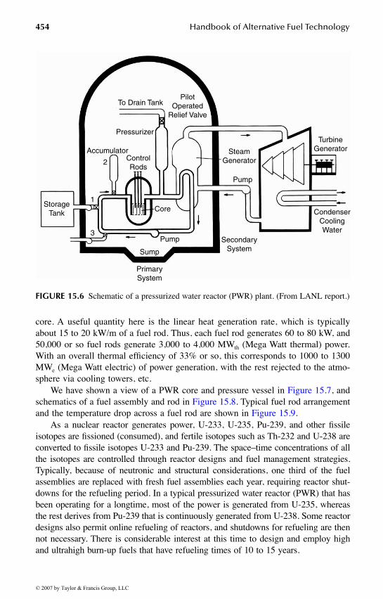
We have shown a typical nuclear power plant schematic in Figure 15.6.A considerable portion of “b” and all of “c” are similar to those in coal-fired
steam plants, and do not require any special elaboration here. We will hence focusmore on part “a,” and we will also discuss parts of “b.”
The reactor core of a modern 1000-MWe reactor is generally composed of about250 reactor fuel assemblies (“bundle”), with each assembly consisting of about 200fuel rods. Thus, there may be about 50,000 fuel rods in the reactor core. Generally,the fuel is UO2, in which the fresh fuel, the uranium, has been enriched to 2 to 4%(by weight) in U-235. The pencil-thin fuel rods are each about 4 m long, and arecontained in individual Zircaloy cans. There is some small spacing (filled with heliumat the beginning) between a rod and its Zircaloy can (“cladding”) to hold xenon,krypton, iodine, and other gases that are released during fission in the fuel. The coreis placed in a thick pressure vessel, and coolant (water) is pumped through the coreat high velocities. Each fuel rod can thus be envisaged as central to a cooling channel,in which the colder water (~573 K) enters the bottom, is heated by the fuel, andexits relatively hot (~610 K) at the top. The high coolant temperature at exit isrequired by 2-T Carnot cycle thermal efficiency considerations, and this in turndictates the choice of coolants, the fuel material, the operating pressure (which canbe as high as 15 MPa to prevent boiling), structural materials, etc. Once the coolantand the fuel are chosen, other design aspects depend on these choices.
During steady operation, there are typical drops in temperature of about 500,200, 30, and 30 K (radial), respectively, across the fuel (from its centerline to surface),the gap, the clad, and the coolant. Obviously, these drops depend on thermophysicalproperties (thermal conductivity) of the materials, the structural conditions of thefuel and clad, the hydrodynamic conditions (the Reynolds and Prandtl numbers),and the heat generation rate in the fuel, and are different at different locations in the
© 2007 by Taylor & Francis Group, LLC
454 Handbook of Alternative Fuel Technology
core. A useful quantity here is the linear heat generation rate, which is typicallyabout 15 to 20 kW/m of a fuel rod. Thus, each fuel rod generates 60 to 80 kW, and50,000 or so fuel rods generate 3,000 to 4,000 MWth (Mega Watt thermal) power.With an overall thermal efficiency of 33% or so, this corresponds to 1000 to 1300MWe (Mega Watt electric) of power generation, with the rest rejected to the atmo-sphere via cooling towers, etc.
We have shown a view of a PWR core and pressure vessel in Figure 15.7, andschematics of a fuel assembly and rod in Figure 15.8. Typical fuel rod arrangementand the temperature drop across a fuel rod are shown in Figure 15.9.
As a nuclear reactor generates power, U-233, U-235, Pu-239, and other fissileisotopes are fissioned (consumed), and fertile isotopes such as Th-232 and U-238 areconverted to fissile isotopes U-233 and Pu-239. The space–time concentrations of allthe isotopes are controlled through reactor designs and fuel management strategies.Typically, because of neutronic and structural considerations, one third of the fuelassemblies are replaced with fresh fuel assemblies each year, requiring reactor shut-downs for the refueling period. In a typical pressurized water reactor (PWR) that hasbeen operating for a longtime, most of the power is generated from U-235, whereasthe rest derives from Pu-239 that is continuously generated from U-238. Some reactordesigns also permit online refueling of reactors, and shutdowns for refueling are thennot necessary. There is considerable interest at this time to design and employ highand ultrahigh burn-up fuels that have refueling times of 10 to 15 years.
FIGURE 15.6 Schematic of a pressurized water reactor (PWR) plant. (From LANL report.)
StorageTank
To Drain Tank
Pressurizer
PilotOperated
Relief Valve
AccumulatorControlRods
Core
Pump
Pump
Sump
PrimarySystem
SecondarySystem
SteamGenerator
TurbineGenerator
CondenserCoolingWater
2
1
3
© 2007 by Taylor & Francis Group, LLC

Nuclear Energy 455
15.2.1 REACTOR CONTROL AND A TOY MODEL
The reactor control requires careful attention to details. Equation 15.5 does not tellthe entire story in that not all neutrons are emitted at the same time, and someneutrons are born “delayed” through some fission products. Also, some fission
FIGURE 15.7 A view of a pressurized water reactor (PWR) core and pressure vessel. (West-inghouse, from Connolly, T.J., Foundations of Nuclear Engineering, John Wiley & Sons,1978. With permission.)
Lifting Lug
Deep Beam
Upper SupportPlate
InternalsSupport Ledge
Core Barrel
Support Column
Inlet Nozzle
Upper Core Plate
Thermal Shield
Reactor Vessel
Access Port
Radial Support
Bottom SupportForging
Control RodDrive Mechanism
Instrumentation PortsThermocouples
Closure HeadAssembly
Thermal Sleeve
Control RodShroud TubeHold–down SpringAligment Pin
Control Rod Guide Tube
Control Rod Drive ShaftControl Rod Cluster(withdrawn)Outer Nozzle
Baffle Former
Former
Fuel Assemblies
Lower Core Plate
Flow Mixer PlateCore Support Columns
Instrumentation ThimbleGuide–neutron Detectors
© 2007 by Taylor & Francis Group, LLC

456 Handbook of Alternative Fuel Technology
products (such as xenon) are strong neutron absorbents, and they have both localand global effects on the reactor criticality, as they are both born (through fissionproducts and their transmutation) and destroyed (through decay and neutron cap-ture) continuously during the reactor operation. The multiplication factor k isfurther dependent on the reactor temperature (for example, there is an increase inneutron absorption in U-238 resonances as the temperature goes up, leading to adecrease in k) and coolant conditions (an increase in temperature leads to lowerdensity or phase change from liquid to vapor, and these changes known as thedensity and void effects, respectively, both lead to a decrease in k). A simple model(a point kinetics, or a toy model) that captures effects of some of these phenomenacould be written as:
FIGURE 15.8 Schematic of a fuel assembly and rod. (From LANL report.)
ControlRod
Cluster
Top Nozzle
Control Rod
Fuel Rod
Spring ClipAssembly
BottomNozzle
FUEL ROD ASSEMBLY
FUEL ROD
FissionGas
Plenum
ZircaloyCladding
Gas-Filled Gap
UO2 Fuel Pellets
3.7 m
1.0 cm
© 2007 by Taylor & Francis Group, LLC

Nuclear Energy 457
(15.12)
with appropriate initial conditions. Here, U is the internal energy of the core, isthe coolant mass flow rate through the core, h is the enthalpy of the coolant, and Pis the power generation in the core. We have,
(15.13)
in which V is the total volume of the core (assuming the cross sections are for thehomogenized core in some sense). Also, βs are fractional coefficients that indicategeneration due to fissions of the delayed neutron precursor “c” (actually there areseveral, but we have shown only one), iodine-135 (I), and xenon-135 (Xe). The
FIGURE 15.9 Fuel rod arrangement with coolant channels in a PWR, and typical temperaturedrop across a fuel rod.
dn t
dt=
k t,U t -1 -n t + c t Xe tc
aXe( ) ( )( )( ) ( ) ( ) −
βλ σ
(( ) ( )
( ) ( ) − ( )
( )
vn t +s(t)
dc t
dt= n t c t
dI t
dt=
ccβ λ
ββ λ
λ λ σ
II
I XeaX
n t I t
dXe t
dt= I t Xe t
( ) − ( )
( ) ( ) − ( ) − ee
out in
Xe t vn t
dU t
dt=P t m t h t h t
( ) ( )
( ) ( ) − ( ) ( ) − ( ))( )
m
P t =VG vn tf f( ) ∑ ( )
Space GridFuel Rod
D
(Dimensions are typicalof PWR designs)
UO2GapCladdingWater
0.0265˝0.0035˝
0.185˝
TemperatureProfile
P
t1
t/2
g
3 2
D
© 2007 by Taylor & Francis Group, LLC

458 Handbook of Alternative Fuel Technology
delayed neutron effects are most important for the routine short-term control of thereactor, whereas other effects are important for both short-term and long-term controlof the reactor.
The multiplication factor k has a complex dependence on the internal energy ofthe core, but this dependence can be expressed in some simple ways through use ofa summation of contributions from separate effects via coefficients that provide ameasure of the change in k with respect to these effects. For example, one constructsthe equation:
(15.14)
and develops it as dictated by insights and measurements or calculations. Thenonlinear system of ordinary differential equations then can be numerically solved,and considerable insights can be gained in the overall working of the system throughsimulations. In fact, simulators based on similar principles have played a verysignificant role in reactor operator training, just as they have been crucial in theaircraft industry.
15.3 NUCLEAR FUEL CYCLE
Natural uranium and thorium, and their compounds and transmuted products (Pu-239 and U-233, respectively) are the fuel resources for nuclear reactors. At present,natural uranium contains 99.3% U-238 and 0.7% U-235 in its compounds. Naturalthorium occurs mainly as Th-232 in its compounds. Th-232 is not fissile, but throughneutron absorption and subsequent decays of products, it can be converted to U-233,which is fissile. As we have noted earlier, through similar processes U-238 isconverted to Pu-239, which is also fissile. Thus, fertile materials such as U-238 andTh-232 can be converted or “bred” into fissile materials. Because both U-238 andTh-232 are plentiful in the earth’s crust, the nuclear fuel resource can be expanded100-fold or more through breeding over the ones that are naturally available in thefissile form. Although all nuclear reactors convert fertile materials into fissile mate-rials, special designs can enhance the breeding ratio (BR), which is defined as:
(15.15)
And it is possible to achieve BR > 1, guaranteeing long-term nuclear fuel supply(thousands of years). BR depends on the neutron spectrum (thermal, epithermal orfast) in the reactor, and the fuel (mainly the fertile content of uranium and thorium,that is U-238 or Th-232 content in the fuel). Note that fast neutrons produce alarger number of neutrons per fission as compared to thermal neutrons, as shownin Figure 15.10.
dk t,U t
dt=
kU
dUdt
( )( ) ∂∂
+ ..
BR=Average rate of production of fissile isotopees
Average rate of loss of fissile isotopes
© 2007 by Taylor & Francis Group, LLC

Nuclear Energy 459
The effect is, however, dependent on the isotope. Significantly, for a fast-neutronspectrum, there is a greater availability of fission-produced neutrons for capture bythe fertile isotopes, which results in a greater production of fissile isotopes. Thus,fast reactors (these are reactors in which neutron spectrum is rich in fast-neutroncontent through avoidance of light moderating materials) can lead to a BR > 1,though certain thermal reactors based on U-233 (and thorium) can also lead to a BR> 1. Generally, however, for all light water reactors BR < 1, and such reactors areknown as converters rather than breeders (for which by definition, BR > 1).
Indeed, as we have noted earlier, nuclear power plants can be built with reactorcores that are either natural uranium based or that use enriched uranium. One canalso use mixed fuels, which are based on various combinations of thorium, uranium,and plutonium. The fissile materials produced in reactors can thus be recycled,either through special reactors or through most reactors of present designs, withappropriate adjustments.
Because nuclear reactors initially developed in the same time frame as nuclearweapons, the development of nuclear reactor power plants in various countrieslargely followed the expertise and resources that were developed in conjunction withnuclear weapons programs. Almost all present-day power plant designs derive fromthe initial work in the U.S., Canada, U.K., Russia (the Soviet Union), France, andSweden. The countries that developed or used uranium technologies for weaponswork preferred slightly enriched uranium (as the technology was already availableto them and the enriched uranium leads to higher power densities, smaller cores,and longer fuel replacement times), whereas the other countries preferred (or hadno other realistic choice) to use natural uranium with graphite or heavy water, withwater or a gas as a coolant. The fuel resource needs for the former are morecomplicated, as the enrichment at the scales needed is an expensive process, and isavailable now only in a few nations.
FIGURE 15.10 Net neutrons produced per absorption in fissile isotopes, as a function of theenergy of the neutron absorbed. (From ERDA-1541, June 1976.)
For U-233, U-235, and Pu–239
Pu–239
U–233
U–235
U–233
U–235Pu–239
10-3 10-2 10-1 100 101 102 103 104 105 106 107
Energy of Neutron Absorbed, eV
4.0
3.0
2.0
1.0
0Neu
tron
Yie
ld p
er N
eutr
on a
bsor
bed,
η
© 2007 by Taylor & Francis Group, LLC

460 Handbook of Alternative Fuel Technology
The nuclear fuel cycle initially involves exploration and mining of uranium andthorium ores. These ores are widely available, and the principal resources are inthe U.S., Russia, China, Australia, South Africa, Gabon, Congo, Niger, India, etc.After mining (through open pit mining or in situ leaching from the ground or rocks),the uranium ore (~0.1% uranium oxide content) is milled (and leached and precip-itated out in an acid solution) to an oxide powder. In this form, the powder is knownas yellowcake (~80% uranium oxide content). The remainder of the ore is knownas the tailings; it is slightly radioactive and toxic, and is a waste that must beproperly disposed of.
At a conversion facility, the yellowcake is first refined to uranium dioxide, whichcan be used as the fuel in reactors that use natural uranium. Further processing,however, is needed if this uranium were to be enriched in U-235 for the reactorsthat require such uranium. For enrichment, the yellowcake is converted into uraniumhexafluoride gas through use of hydrogen fluoride and is shipped in containers toan enrichment facility where either a diffusion or a centrifuge process is used (othermethods such as Laser Isotope Separation are still not in commercial use). The firstprocess relies on a slight difference in the diffusion of the U-235 hexafluoridemolecule from that of the U-238 hexafluoride molecule through a membrane (thediffusion coefficient is inversely proportional to the square root of the molecularmass), whereas the second method relies on the mass difference (inertia) betweenthe two molecules.
In practice, thousands of stages are used. The diffusion process is highly energyintensive because of the pumping requirements, whereas the centrifuge processrequires special rotor materials, motors, bearings, etc. (the practical details are notin the public domain but are reported to have been clandestinely disseminated to anumber of countries in the last few years). The enriched uranium hexafluoride isnext reconverted to produce enriched uranium oxide. This oxide then is sintered(baked) at a high temperature (over 1400°C) to produce pellets, which are then usedin fuel rods and assemblies. In all this processing, great care is taken to ensurequality control with respect to content of fuel and its size and shape. Extensiveefforts are also made to avoid accidental criticality.
As the reactor fuel is used in a reactor, it undergoes enormous transformations.The fissile isotopes are fissioned and lead to fission products, neutrons, other radi-ation, and heat (as discussed earlier). The neutrons transmute the fission productsand also produce many actinide species through absorption in the fertile isotopes(some of which will fission again). The fuel cracks because of heat and stresses, thefission products migrate within the fuel, and gases such as xenon and iodine accu-mulate in the gap between a fuel rod and its cladding. The degradation in the fuelthermophysical properties requires that the fuel be taken out of the reactor after acertain time period, and that fresh fuel replace it. This generally is a batch processin that in most reactors, this “refueling” is done once a year when a reactor is shutdown for a couple of weeks, and approximately one third of the reactor core isreplaced. The fuel that is taken out of the reactor would have been generally usedfor a period of about 3 years, and is known as the spent fuel. There are certainreactors in operation (the CANDU reactor, which we will discuss later) in whichthe refueling is done online, and a shutdown is not required.
© 2007 by Taylor & Francis Group, LLC
Nuclear Energy 461
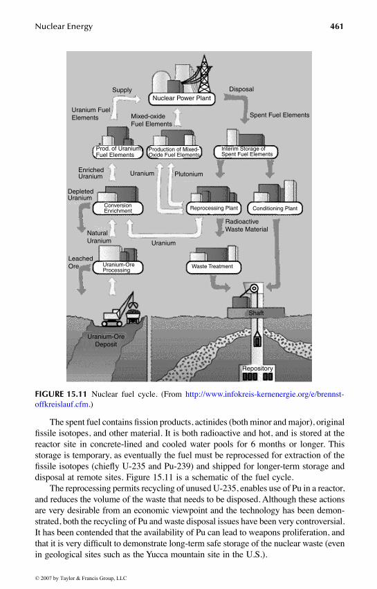
The spent fuel contains fission products, actinides (both minor and major), originalfissile isotopes, and other material. It is both radioactive and hot, and is stored at thereactor site in concrete-lined and cooled water pools for 6 months or longer. Thisstorage is temporary, as eventually the fuel must be reprocessed for extraction of thefissile isotopes (chiefly U-235 and Pu-239) and shipped for longer-term storage anddisposal at remote sites. Figure 15.11 is a schematic of the fuel cycle.
The reprocessing permits recycling of unused U-235, enables use of Pu in a reactor,and reduces the volume of the waste that needs to be disposed. Although these actionsare very desirable from an economic viewpoint and the technology has been demon-strated, both the recycling of Pu and waste disposal issues have been very controversial.It has been contended that the availability of Pu can lead to weapons proliferation, andthat it is very difficult to demonstrate long-term safe storage of the nuclear waste (evenin geological sites such as the Yucca mountain site in the U.S.).
FIGURE 15.11 Nuclear fuel cycle. (From http://www.infokreis-kernenergie.org/e/brennst-offkreislauf.cfm.)
Supply
Uranium FuelElements
Nuclear Power PlantDisposal
Mixed-oxideFuel Elements
Spent Fuel Elements
Prod. of UraniumFuel Elements
EnrichedUranium
DepletedUranium
Uranium Plutonium
Production of Mixed-Oxide Fuel Elements
Interim Storage ofSpent Fuel Elements
Reprocessing Plant Conditioning PlantConversionEnrichment
Uranium-OreProcessing
Waste Treatment
RadioactiveWaste Material
Uranium
NaturalUranium
LeachedOre
Uranium-OreDeposit
Shaft
Repository
© 2007 by Taylor & Francis Group, LLC

462 Handbook of Alternative Fuel Technology
We have shown a typical material balance for the fuel needed for the annualoperation of a 1000 MWth reactor in Figure 15.12.
15.4 TYPES OF REACTORS
We have discussed the PWR design earlier. Other types of reactors in present useare as follows:
The boiling water reactor (BWR): This type of reactor differs from a PWR inthat water is allowed to boil fully in the upper portions of the reactor core,and no heat exchanger loop (the secondary) is used. The water is maintainedat about 6–7 MPa (instead of 15.5 MPa as in a PWR). The steam passesthrough a separator at the top of the core and then goes on to drive turbines;the condensed water is pumped back to the core. The steam does containsome radioactive material, and so a modest shielding on the turbine side isrequired. Lower pressures and avoidance of steam generators simplify theplant design, but then there is the additional complication of two phase flowsin the core. Also, the pressure vessel is larger (it needs to accommodate theseparator) and the control blades are inserted from the bottom, therebyprecluding gravitational insertion of control rods in an emergency. Severaldifferent designs of BWRs and their containments are presently in existence,but in the U.S. these reactors are designed only by the General Electric Co.We have shown a schematic of a BWR in Figure 15.13.
FIGURE 15.12 Uranium ore needed for annual operation of a 1000-MWth reactor and theassociated material balance and waste.
Ore146,000 MT
Tailings145,800 MT
Yellowcake150 MT
Depleted Uranium117 MT
Enriched UF633 MT
UO2 Fuel33 MT
Spent Fuel
31.5 MT of depleted U1.2 MT of fission products
300 Kg of Pu
© 2007 by Taylor & Francis Group, LLC

Nuclear Energy 463
The pressurized heavy water reactor (PHWR): These reactors, sometimes alsoknown as CANDU because of their primary development in Canada,employ heavy water as a moderator and either the heavy water or lightwater or both as a coolant. These reactors use natural uranium or slightlyenriched uranium and pressurized tubes for the coolant, thereby avoidinglarge pressure vessels. Because of the use of the tubes, fuel can be replaced“online” without a reactor shutdown for refueling.
The graphite-moderated gas cooled reactors (Magnox and HTGR): Thesereactors use graphite as a moderator and a gas (CO2 or Helium) as a coolant.Because, like heavy water, graphite is a good moderator and a poor neutronabsorber, graphite-moderated reactors can use natural uranium as fuel. Notethat a gas, because of its low density, is quite transparent to neutrons. Gasesare, however, poor coolants as compared to liquids, and these reactors havelow specific heat generation and comparatively large surface areas and,hence, large volumes. But one can achieve very high temperatures (hencethe name high-temperature gas reactor) as phase changes and dissociationsor surface reactions can be avoided, particularly with the use of a noble gassuch as helium. However, helium does pose a difficulty both in terms of itscost (in countries other than U.S.) and the ease of its leakage from the system.
The graphite-moderated water-cooled reactors (RBMK types): These reactorsuse graphite as a moderator and light water as a coolant. Natural uraniumor slightly enriched uranium can be used as fuel. The Chernobyl reactorwas this type. These reactors are more compact as compared to the gas-cooled reactors, and also put less demands on coolant pumping power.These reactors, however, can have a positive temperature coefficient in thatunder certain circumstances an increase in reactor power can lead to anadditional automatic increase in power (a positive feedback). Thus, if othermeans of automatic or manual control of the reactor are disabled, an increasein reactor power could potentially occur that would terminate only after anexcursion and reactor core disassembly, resulting in serious damage to theplant and, possibly, its surroundings.
Liquid metal fast breeder reactors (LMFBR): The breeding ratio depends onaverage neutron energy as the cross sections for absorption and fission are
FIGURE 15.13 Schematic of a boiling water reactor. (Courtesy U.S. Department of Energy.)
Steam Line
Core
Reactor
Pump
Turbine Generator
CondenderCondenser
Cooling Water
© 2007 by Taylor & Francis Group, LLC

464 Handbook of Alternative Fuel Technology
functions of neutron energy. For uranium-fueled reactors, a fast spectrum(that is, the neutrons are mostly at energies higher than 100 keV or so) canlead to a breeding higher than unity. The need for a fast spectrum precludesuse of low atomic mass materials in the reactor core (excepting gases,which, because of their low density, have large mean free paths for neutronsat all energies). This requires consideration of liquid metals or their alloys.Sodium, lead-bismuth, and mercury have all merited consideration, andseveral power reactors have been built, tested, and extensively used withsodium as a coolant. Generally, the cores are designed with zones of dif-ferent fuel compositions (seed and blanket) to maximize breeding andfacilitate fuel reprocessing. Sodium does pose challenges because of itscorrosiveness and high melting point (it is solid at room temperature), butit is an excellent coolant. One of the earliest reactors to produce electricpower was the Experimental Breeder Reactor-I. The Experimental BreederReactor-II (EBR-II) operated for a long time. The Fast Fuel Test Facility(FFTF) was a sodium-cooled test reactor, and so is the Kalpakkam reactorin India. The French Phoenix and Super Phoenix reactors both have beenLMFBRs, and have produced power. In the U.S., the experience has beenmixed. The Fermi-I, the first commercial LMFBR built near Detroit, waseventually shut down because of a flow blockage and consequent temper-ature rise that damaged the core. The Clinch River reactor was abortedbecause of economic and political considerations. We have shown a sche-matic of a LMFBR in Figure 15.14.
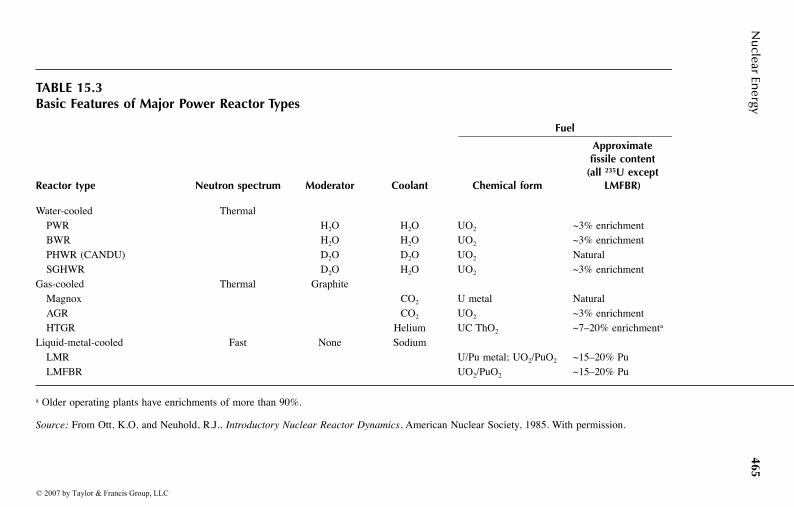
We have summarized the basic features of these reactor types and their thermo-dynamic parameters in Table 15.3 and Table 15.4, respectively.
The nationwide distribution of nuclear power plants is shown in Table 15.5.Table 15.6 shows the distribution of reactors by their types. These data are currentas of April 2003.
FIGURE 15.14 Schematic of a liquid metal fast breeder reactor. (Courtesy U. S. Departmentof Energy.)
PrimarySodium Coolant
SecondarySodium Coolant Steam Line
Core
ReactorHeat
ExchangerSteam
Generator
Condenser
Turbine Generator
CondenserCooling Water
Pump Pump Pump
© 2007 by Taylor & Francis Group, LLC
Nu
clear Energy
465
TABLE 15.3Basic Features of Major Power Reactor Types
Fuel
Reactor type Neutron spectrum Moderator Coolant Chemical form
Approximatefissile content
(all 235U except LMFBR)
Water-cooled ThermalPWR H2O H2O UO2 ~3% enrichmentBWR H2O H2O UO2 ~3% enrichmentPHWR (CANDU) D2O D2O UO2 NaturalSGHWR D2O H2O UO2 ~3% enrichment
Gas-cooled Thermal GraphiteMagnox CO2 U metal NaturalAGR CO2 UO2 ~3% enrichmentHTGR Helium UC ThO2 ~7–20% enrichmenta
Liquid-metal-cooled Fast None SodiumLMR U/Pu metal; UO2/PuO2 ~15–20% PuLMFBR UO2/PuO2 ~15–20% Pu
a Older operating plants have enrichments of more than 90%.
Source: From Ott, K.O. and Neuhold, R.J., Introductory Nuclear Reactor Dynamics, American Nuclear Society, 1985. With permission.
© 2007 by Taylor & Francis Group, LLC

466H
and
bo
ok o
f Altern
ative Fuel Tech
no
logy
TABLE 15.4Typical Characteristics of the Thermodynamic Cycles for Six Reference Power Reactor Types
Characteristic BWR PWR(W) PHWR HTGR AGR LMFBR
Reference designManufacturer General Electric Westinghouse Atomic Energy of Canada, Ltd. General Atomic National Nuclear Corp. NovatomeSystem (reactor station) BWR/6 (Sequoyah) CANDU-600 (Fulton) HEYSHAM 2 (Superphenix)Steam-cycle
No. coolant systems 1 2 2 2 2 3Primary coolant H2O H2O D2O He CO2 Liq. NaSecondary coolant — H2O H2O H2O H2O Liq. Na/H2O
Energy conversionGross thermal power, MW(th) 3579 3411 2180 3000 1550 3000Net electric power, MW(e) 1178 1148 638 1160 618 1200
Efficiency (%) 32.9 33.5 29.3 38.7 40.0 40.0Heat transport system
No. primary loops and pumps 2 4 2 6 8 4No. intermediate loops — — — — 8No. steam generators — 4 4 6 4 8Steam generator type — U tube U tube Helical coil Helical coil Helical coil
Thermal hydraulicsPrimary coolant
Pressure (MPa) 7.17 15.5 10.0 4.90 4.30 ~0.1Inlet temp. (°C) 278 286 267 318 334 395Average outlet temp. (°C) 288 324 310 741 635 545Core flow rate (Mg/s) 13.1 17.4 7.6 1.42 3.91 16.4Volume (L) or mass (kg) — 3.06 × 10⁵ 1.20 × 10⁵ (9550 kg) 5.3 × 10⁶ (3.20 × 10⁶ kg)
Secondary coolantPressure (MPa) — 5.7 4.7 17.2 16.0 ~0.1/17.7Inlet temp. (°C) — 224 187 188 156.0 345/235Outlet temp. (°C) — 273 260 513 541.0 525/487
© 2007 by Taylor & Francis Group, LLC

Nuclear Energy 467
15.4.1 ADVANCED REACTORS AND CONCEPTS
Over the past 60 years, many nuclear reactor designs have been considered. Manyhave been utilized for commercial and routine production of electric power. Con-sidering that France produces almost 70% of its electric power needs through existingnuclear reactor designs, it should be clear that given the political will and publicacceptance, power plants based on the existing designs can provide electric powerto most countries in the immediate future.
TABLE 15.5Nuclear Power Units by Nation
In operation Total
Nation # units Net MWs # units Net MWs
Argentina 2 1,018 3 1,710Belgium 7 5,680 7 5,680Brazil 2 1,901 3 3,176Bulgaria 4 2,722 4 2,722Canada 22 15,113 22 15,113China 7 5,426 11 8,764China (Taiwan) 6 4,884 8 7,584Czech Republic 4 1,648 6 3,610Finland 4 2,656 4 2,656France 59 63,203 59 63,203Germany 20 22,594 20 22,594Hungary 4 1,755 4 1,755India 14 2,548 22 6,128Iran 0 0 1 916Japan 53 44,041 58 48,883Lithuania 2 2,370 2 2,370Mexico 2 1,364 2 1,364Netherlands 1 452 1 452North Korea 0 0 2 2,000Pakistan 2 425 2 425Romania 1 655 5 3,135Russia 27 20,799 33 26,074Slovakia 6 2,512 8 3,392Slovenia 1 656 1 656South Africa 2 1,800 2 1,800South Korea 18 14,970 22 18,970Spain 9 7,565 9 7,565Sweden 11 9,460 11 9,460Switzerland 5 3,220 5 3,220Ukraine 13 11,195 18 15,945United Kingdom 31 11,802 31 11,802United States 104 99,034 107 102,637Totals 443 363,468 493 405,761
© 2007 by Taylor & Francis Group, LLC

468 Handbook of Alternative Fuel Technology
However, from a long-range technical point of view, as well as current andanticipated socioeconomic and political viewpoints, it is important to consider newreactor designs. The historical development of nuclear power plants is well depictedby Figure 15.15.
A major consideration in the new developments is the desire to extend theutilization of fuel resources through breeding of fertile material (which are plentifulbut do not directly produce energy) to fissile material (which are not plentiful butproduce energy), and minimization of nuclear waste material. Figure 15.16 showshow the advancements would lead to less waste and more sustainable energyproduction.
TABLE 15.6Nuclear Power Units by Reactor Type
In operation Total
Reactor type # unitsNet MWe # units
Net MWe
Pressurized light-water reactors (PWR) 262 236,236 293 264,169Boiling light-water reactors (BWR) 93 81,071 98 87,467Gas-cooled reactors, all types 30 10,614 30 10,614Heavy-water reactors, all types 44 22,614 54 27,818Graphite-moderated light-water reactors (LGR) 13 12,545 14 13,470Liquid metal-cooled fast-breeder reactors (LMFBR) 2 793 5 2,573Totals 444 363,873 494 406,111
FIGURE 15.15 Historical progression of nuclear reactor development. (From A TechnologyRoad Map for Generation IV Nuclear Energy Systems, USDOE, 2002.)
Generation IGeneration II
Generation IIIGeneration III+
Generation IV
Early PrototypeReactors Comercial Power
Reactors AdvancedLWRs Evolutionary
Design OfferingImprovedEconomics forNear-TermDeployment
– Shippingport– Dresden, Fermi I– Magnox – LWR-PWR, BWR
– CANDU– AGR
– ABWR– System 80+
Gen I Gen II Gen III Gen III+ Gen IV1950 1960 1970 1980 1990 2000 2010 2020 2030
– Highly Economical– Enhanced Safety– Minimal Waste– Proliferation Resistant
© 2007 by Taylor & Francis Group, LLC

Nuclear Energy 469
Two types of initiatives have received broad industrial and government supportin this regard:
1. The first initiative consists of some incremental but important modificationsof the existing designs. These modifications are based on the criteria ofcredible plans for regulatory acceptance, existence of industrial infrastructure,commercialization, cost-sharing between industry and government, demon-stration of economic competitiveness, and reliance on existing fuel cycleindustrial structure. The reactor designs that have emerged are the AdvancedBoiling Water Reactor (ABWR-1000, ESBWR), the Advanced PressurizedWater Reactor (AP600, AP1000, SWR-1000), Pebble Bed Modular Reactor(PBMR), International Reactor and Innovative and Secure (IRIS), and Gas-Turbine Modular Helium Reactor (GT-MHR). These reactors, and the dem-onstration plants, could come in operation by the year 2010.
2. The second initiative,22 known as the Generation IV Initiative (the GEN-IV Initiative), has the goals of sustainability (the ability to meet the needsof present generations while enhancing and not jeopardizing the abilityof future generations to meet society’s needs indefinitely into the future),Safety and Reliability, Economics, and Proliferation Resistance and Phys-ical Protection. The emphasis here is on reactor concepts and associatednuclear energy systems that will satisfy the following criteria:a. Meet clean air objectivesb. Promote long-term availability of systems and effective fuel utilization
for worldwide energy productionc. Excel in safety and reliabilityd. Have very low likelihood and degree of reactor core damagee. Eliminate the need for off-site emergency responsef. Have a clear life-cycle cost advantage over other energy sourcesg. Have a level of financial risk comparable to other energy sourcesh. Provide assurance against diversion or theft of weapons-usable materialsi. Provide physical security of the reactor and facilities
FIGURE 15.16 Gain in sustainable nuclear resources with Pu-recycling. (From A TechnologyRoad Map for Generation IV Nuclear Energy Systems, USDOE, 2002.)
© 2007 by Taylor & Francis Group, LLC

470 Handbook of Alternative Fuel Technology
Nearly 100 concepts that can be generally classified in the broad categories ofwater cooled, gas cooled, liquid metal cooled, and nonclassical (molten salt, gas-core, heat pipe, and direct energy conversion) have been proposed and considered.Six leading candidates that have been identified for research funding by the U.S.Department of Energy are:
• Gas-cooled fast reactor (GFR)• Lead-cooled fast reactor (LFR)• Molten salt reactor (MSR)• Sodium-cooled fast reactor (SFR)• Supercritical water-cooled reactor (SWCR)• Very-high-temperature reactor (VHTR)
We have shown their schematics in Figure 15.17 and summarized importantparameters in Table 15.7.
FIGURE 15.17A Schematics of GEN-IV reactors. (a) Gas-cooled fast reactor (GFR) (FromA Technology Road Map for Generation IV Nuclear Energy Systems, USDOE, 2002.)
Gas-Cooled Fast Reactor
Helium
Generator
Turbine
ElectricalPower
ReactorCore
Reactor
ControlRods
Heat Sink
Recuperator
Compressor
PreCooler
HeatSink
Compressor
Intercooler
© 2007 by Taylor & Francis Group, LLC

Nuclear Energy 471
FIGURE 15.17B Schematics of GEN-IV reactors. (b) Lead-cooled fast reactor (LFR) (FromLapeyre, B., Pardoux, E., and Sentis, R., Introduction to Monte-Carlo Methods for Transportand Diffusion Equations, Oxford, 2003, original in French, 1998. With permission.)
FIGURE 15.17C Schematics of GEN-IV reactors. (c) Molten salt reactor (MSR) (FromLapeyre, B., Pardoux, E., and Sentis, R., Introduction to Monte-Carlo Methods for Transportand Diffusion Equations, Oxford, 2003, original in French, 1998. With permission.)
Lead-Cooled Fast Reactor
ControlRods
Header
U-Tube HeatExchangerModules (4)
Reactor Module/Fuel Cartridge(Removable)
CoolantModuleCoolant
InletDistributor Reactor
ReactorCore
Generator
Turbine
ElectricalPower
Recuperator
Compressor
Heat Sink
IntercoolerCompressor
Heat SinkPreCooler
Molten Salt ReactorControlRods
ReactorCoolant Salt
PurifiedSalt
FuelSalt
ChemicalProcessing
Plant
Pump
FreezePlug
Pump
HeatExchange
HeatExchange
Emergency Dump Tanks
Compressor
Intercooler
PreCooler Heat Sink
Recuperator
Turbine
Generator ElectricalPower
Compressor
HeatSink
© 2007 by Taylor & Francis Group, LLC

472 Handbook of Alternative Fuel Technology
FIGURE 15.17D Schematics of GEN-IV reactors. (d) Sodium-cooled fast reactor (SFR)(From Lapeyre, B., Pardoux, E., and Sentis, R., Introduction to Monte-Carlo Methods forTransport and Diffusion Equations, Oxford, 2003, original in French, 1998. With permission.)
FIGURE 15.17E Schematics of GEN-IV reactors. (e) Supercritical water-cooled reactor(SWCR) (From Lapeyre, B., Pardoux, E., and Sentis, R., Introduction to Monte-Carlo Methodsfor Transport and Diffusion Equations, Oxford, 2003, original in French, 1998. With permission.)
© 2007 by Taylor & Francis Group, LLC

Nuclear Energy 473
Interesting as these concepts are, they do not constitute a radical departure fromthe reactor designs of the past. The research and development issues with theseGEN-IV reactors are mostly related to long-term operations at high temperatures,and thus concern materials compatibility, corrosion and damage, safety (particularlyfor fast spectra), and fuel processing and recycling. But basically, the GEN-IVreactors are recycles of old designs, and no new physics is involved.
An interesting design concept under exploration is the accelerator-driven reac-tor.34 In this design a proton beam is used to strike a lead or other heavy target,creating high-energy (fast) neutrons (known as spallation neutrons). These neutronsdrive an otherwise subcritical reactor, and a steady state of neutron population ismaintained in a subcritical (k < 1) reactor (see Equation 15.5, where dn/dt = 0, buts ≠ 0, leads to ). These reactors avoid any chances of large reactivityinsertions and, hence, large reactor accidents. These reactors can use any fissilematerial and have breeding ratios because of fast spallation neutrons. These designsare receiving some attention in the international community.
We should also note that all the preceding designs rely on conversion of fissionheat through a thermodynamic steam or gas cycle to electricity and thus have lowconversion efficiencies (maximum of about 50%). There are research efforts under-way to explore direct conversion schemes in which the fission energy can be first
FIGURE 15.17F Schematics of GEN-IV reactors. (f) Very-high-temperature reactor. (From ATechnology Road Map for Generation IV Nuclear Energy Systems, USDOE, 2002.)
ControlRods
GraphiteReactor
Core
GraphiteReflector
Pump
Blower
Reactor HeliumCoolant
HeatExchange
Heat Sink
HydrogenProduction Plant
Hydrogen
Oxygen
Water
Very-High-Temperature Reactor
n k= −( ) / ( )s 1
© 2007 by Taylor & Francis Group, LLC

474H
and
bo
ok o
f Altern
ative Fuel Tech
no
logy
TABLE 15.7Some Technical Specifications of GEN-IV Reactors
Reactor Parameter
Reactor Type
GFR LFR MSR SFR SCWR VHTR
Power 600 MWth 125–400 MWth 1000 MWe 1000–5000 MWth 1700 MWe 600 MWth
Net plant efficiency % 48 44 to 50 44 >50Reference fuel compound UPuC/SiC with
about 20% PuMetal alloy or
nitrideU or Pu fluorides
dissolved in Na/ZR fluorides
Oxide or metal alloy
UO2 with stainless-steel or Ni-alloy
cladding
ZrC-coated particles in blocks,
pins or pebblesModerator N/A N/A Graphite N/A Water GraphiteCoolant Helium Lead-eutectic Sodium Water HeliumCoolant inlet/outlettemperature °C
490/850 NA/550 565/700(850) NA/550 280/510 640/1000
Coolant pressure (bar) 90 1 1 250 VariableNeutron spectrum Fast Fast Thermal Fast Thermal/fast ThermalConversion (breeding) ratio Self-sufficient 1.0 Burner 0.5–1.30Average power density (MWth/m3)
100 22 350 100 6–10
Burnupa Damage 5% FIMA:60 dpa
100GWD/MTHM
150–200GWD/MTHM
45 GWD/MTH10–30 dpa
Earliest deployment 2025 2025 2025 2015 2025 2020
a GWD = Giga Watt days; MTHM = metric tonne heavy metal; dpa = displacements per atom; FIMA = fissions of initial metal atoms; N/A = not applicable; NA = not available.
Source: From A Technology Road Map for Generation IV Nuclear Energy Systems, USDOE, 2002.
© 2007 by Taylor & Francis Group, LLC

Nuclear Energy 475
converted to photonic energy through formation of excimers and photonic emissionsby these excimers, and then the conversion of this photon energy to electric energythrough the use of photoelectronic devices. In principle, one might then be able toget higher conversion efficiencies as a 2T Carnot cycle is avoided.36
15.4.2 HYDROGEN PRODUCTION
Fuel cells for automotive transport will require hydrogen. It has been suggested thatnuclear energy (reactors) may provide a very effective means of generating hydrogen.The schemes under consideration include37:
• Steam methane reforming, using nuclear energy for the endothermic heatof reaction
• Conventional electrolysis, using nuclear-generated electricity• Thermochemical cycles for water splitting• Hybrid cycles combining thermochemical and electrolytic steps• High-temperature electrolysis using nuclear electricity and heat
The steam–methane reformation is based on the reaction
(15.16)
The advantage of using nuclear energy to produce steam for this above processis that the process itself has been extensively studied. The use of nuclear energy toproduce steam avoids the need of methane combustion to produce steam, and theCO2 so produced is easier to sequester than CO2 resulting from methane burning.The disadvantages are that the CO2 is nevertheless produced and needs to be seques-tered. Also, a large amount of methane (natural gas) is used.
In the thermochemical cycle under consideration (see Figure 15.18), the nuclear-generated heat is used to split hydrogen from water through use of sulfur dioxideand iodine reactions. The process has the advantage that the raw stocks (iodine andsulfur dioxide) are not consumed, and are recycled. Its disadvantages are that a high-temperature reactor must be built to test the idea.
The high-temperature electrolysis process is quite straightforward as shown inFigure 15.19, but it has a lower conversion efficiency than that of the thermochemi-cal cycle.
Note that both the VHTR of the GEN-IV designs would also be quite suitablefor hydrogen production because of the high temperature of the exiting helium.
15.5 PUBLIC CONCERNS OF SAFETY AND HEALTH
Public concerns regarding safety and health issues associated with the operation ofnuclear reactors have their genesis in the dread of nuclear weapons, and the fact thatthe developments of the weapons and the nuclear reactors have overlapped andproceeded in a coincident time frame. Fission weapons are, however, characterizedby small size; the explosive part is only a few centimeters in diameter. Power density
CH + 2H O + 185 kJ CO + 4H4 2 2 2→
© 2007 by Taylor & Francis Group, LLC

476 Handbook of Alternative Fuel Technology
FIGURE 15.18 The thermochemical cycle for producing hydrogen from water and nuclearenergy. (Courtesy of INEL.)
FIGURE 15.19 High-temperature electrolysis using heat and electricity generated from ahigh-temperature gas reactor. (From A Technology Road Map for Generation IV NuclearEnergy Systems, USDOE, 2002.)
HydrogenNuclear Heat
Oxygen
H2
H2
2I
2
2 2 2
2 4
2 4
I
2I
2 H I
2 H II (Iodine)Circulation
400 C 900 C
RejectedHeat 100 C
H SO
H O
2H O2H O
Water
SO + H O
2 2SO + H O
S (Sulfur)Circulation
S O2
H SO
12 2O
12
+
O
High-temperatureheatexchanger
He
He
He
He
HeHe
He
H2, H2O separator
H2O
H2O
H2
Make-upwater
Heatexchanger
High-temperature
steamelectrolysis
unitH2O + H2
Recuperator
Primaryheat
rejection
LP compressor
HPcompressor
GasTurbine
Electricalgenerator
Power to grid
Power for electrolysis
HTGR
Inte
rcoo
ler
© 2007 by Taylor & Francis Group, LLC

Nuclear Energy 477
is extremely high, and explosion time is a few microseconds. The design is specificto achieving the explosion in that the fissile material is compressed and brought tosupercriticality and kept supercritical for a short time frame in a specific fashion,and the neutrons are introduced at an appropriate time to get the desired explosiveenergy release. Commercial nuclear reactors, on the other hand, are large with coresthat are approximately 12 ft in diameter. Their power density is low. Also, energyis produced over a long period of time. Design safeguards protect against powerexcursions of the type the weapons are designed for.
Generally, in a nuclear explosion 50% of the damage comes from thermalradiation, 35% from the blast, and only the remaining 15% comes from the shortterm and delayed radiation (beta, gamma, and alpha radiation associated with decayof radioisotopes). The radiation can cause cellular, glandular, and DNA damage andinduce cancer through inhalation or other means of exposure (digestion or skinexposure). The thermal radiation and the blast are not the causes of concern withrespect to nuclear reactors, as the reactors cannot explode like weapons. But allreactors can encounter circumstances in which the rate of heat generation in thereactor core exceeds the heat removal rate. Let us consider the first law of thermo-dynamics as applied to the entire reactor core (we neglect conduction and radiationlosses, etc., to simplify the arguments):
(15.17)
where U is the internal energy of the core, is the coolant mass flow rate throughthe core, h is the enthalpy, and P is the power generation in the core. The steadystate corresponds to the two terms on the right balancing out, but obviously if thesecond term exceeds the first, the core will heat up. For example, if the coolant flowslows down or stops owing to a breakage of piping or loss of power to a pump, andP is not reduced correspondingly, the core will heat up. Similarly, if P is increased,but is not (or if hout is not, which relates to conditions at the exit and, hence, theconvective heat transfer coefficient between the fuel and the coolant), the core canagain heat up.
Under normal operations, these imbalances are adjusted through passive andactive controls. Most reactors are also designed to be somewhat inherently safe inthat an increase in fuel or coolant temperature leads to an automatic reduction ink and, hence, the power generation P. Also, expansion of the core leads to a reductionin k and, hence, P. The rate constants are affected by delayed emission of neutrons,and thermal reactors have most neutrons at relatively slow speeds, thus reducingthe overall rate of increase of neutron populations should k be increased acciden-tally. Thus, generally with most reactors, concerns are focused more on accidentsthat start with loss of coolant flow or the coolant itself, and rapid increase in powerP that, for example, could result from sudden withdrawal or lack of insertion of acontrol rod.
dU t
dt=-m t h t -h t +P tout in
( ) ( ) ( ) ( )( ) ( )
m
m
© 2007 by Taylor & Francis Group, LLC

478 Handbook of Alternative Fuel Technology
Under normal conditions, radioactive isotopes are contained in the fuel rods. Thecladding, water coolant system, piping and pressure vessel, containment, and engi-neered safety features (sprays, ice condensers, suppression pools, etc.) are designed tolimit the release of radioactive isotopes during accidents (see Figure 15.20). Naturalprocesses (physicochemical reactions, deposition, settling, coagulation, fragmentation,aerosol growth, etc.) may act to reduce or enhance the release fractions.
Overall, there are several aspects of the nuclear fuel cycle that have been causesof public concern:
• Release of radioactive material to the environment during the mining,processing, and transport (shipping) of fresh or used nuclear fuel
FIGURE 15.20 Cross section of a typical containment building for a pressurized waterreactor (PWR). The concrete building houses the entire primary system, the pressure controlsystem, ventilation equipment, and part of the emergency core-cooling system. The variouscomponents are encased in concrete and surrounded by a 0.63 cm thick steel liner. (FromLos Alamos Science, Vol. 2, No. 2., Los Alamos Scientific Laboratory, 1981. With permission.)
Steel Liner
ReactorsCoolant Pumps
ReactorVessel
SteamGenerators
Sump
Overhead Crane
170’
© 2007 by Taylor & Francis Group, LLC

Nuclear Energy 479
• Releases of radioactive material during normal operation or accidents atnuclear power plants
• Short-term and long-term storage of nuclear waste, and releases from thestorage sites
• Proliferation of technology and the attendant risk of terrorism
Nuclear industry, utility groups, national governments, and the InternationalAtomic Energy Agency (IAEA) have all addressed these issues in depth, and stringentregulations at national levels, as well as guidance at international levels, have beenformulated. These are enforced or followed to reduce risks to the public from postu-lated or real accidents. Yet, it must be realized that accidents have occurred, and willoccur, and neither accidents nor releases of radionuclides can be completely pre-vented. The best one can do is reduce the probabilities of accidents, and then whenthe accidents do occur, reduce the consequences associated with them. But riskmanagement is expensive, and good risk–benefit and cost–benefit analysis are neededto arrive at regulatory requirements that would find public and institutional sup-port.38–45 This support has varied greatly in different countries and at different times.
Table 15.8 gives the half-lives and radioactive inventories of some importantisotopes that are produced in a nuclear power plant. Health hazards are largelyassociated with the longer-lived, volatile isotopes of I, Cs, Sr, Pu, Ru, and Te, whichemit beta and gamma radiation, and Pu and other actinides that emit alpha particlesand neutrons also.
Accident sequences that can cause vaporization of reactor inventory are thoseinitiated by a loss of coolant, accidents, and severe transients (primary coolant pipebreak, main steam line break in a PWR, control rod ejection, pressure vessel failure,etc.). Details of such sequences are discussed in Reactor Safety Study (WASH-1400).
The amount and timing of the release of radioactive substances from a reactorplant to the environment is referred to as a nuclear source term. More broadly, sourceterms are characterized by the radionuclides that are released to the environment aswell as the time dependence of the release, the size distributions of the aerosolsreleased, the location (elevation) of the release, the time of containment failure, thewarning time, and the energy and momentum released with the radioactive material.The definition of the source term is slightly loose as different computer programsmay require different inputs. Still, it is clear that source terms will be closely relatedto the vapors, gases, and particles in suspension in the reactor containment (orbuilding) at a given time, and the states of this suspension and the containment. Ifa containment does not fail (and is not bypassed) then, regardless of the complicatedphenomenology that takes place inside the containment during the accident, thesource term would be zero, and no direct harmful effects to the public would result.
The determination of source terms within well-defined bounds is not simple. First,a range of severe accident scenarios, with corresponding initiating events, must bestudied. Using probabilistic methods (fault and event trees), a probability of occur-rence can then be assigned to the given accident scenario. Next, an integrated analysisof all that occurs in the plant needs to be carried out. Detailed physicochemical,neutronic, and thermal hydraulic models with an extensive database (separate effects)and integrated computer programs (as verified against a range of integral experiments)
© 2007 by Taylor & Francis Group, LLC

480 Handbook of Alternative Fuel Technology
are required. This task can be quite overwhelming as the number of molecular speciesinvolved is large, temperatures and pressures can be high, and the associated flowscan be quite complex. High radiation fields are also present and, depending on thespecific type of accident, the situation can be very dynamic.
Note that in 1957, the WASH-740 reports recommended an exclusion zone ofradius R (miles) around a nuclear plant of power P (MWth), based on the formula:
This formula is not based on realistic estimates. Rather, all material from the plantis assumed to disperse without any mitigating mechanisms. In 1957, the Windscaleaccident occurred, in which 100% of the noble gases, 12% of the I inventory, and 10%of Cs inventory of the core were released to the environment. This accident was the
TABLE 15.8Important Radioactive Nuclides (in a 3412-MWth PWR operated for 3 years, as predicted by computations)
RadionuclideHalf-Life
(days)Inventory (Ci × 10–8) Radionuclide
Half-Life(days)
Inventory (Ci × 10–8)
Iodine isotopes
I-131 8.05 0.87 I-133 0.875 1.8I-132 0.0958 1.3 I-135 0.280 1.7
Noble gases
Kr-85 3.950 0.0066 Kr-88 0.117 0.77Kr-85m 0.183 0.32 Xe-133 5.28 1.8Kr-87 0.0528 0.57 Xe-135 0.384 0.38
Cesium isotopes
Cs-134 7.5 × 10² 0.13 Cs-137 1.1 × 10⁴ 0.065
Other fission products
Sr-90 1.103 × 10⁴ 0.048 Ba-140 1.28 × 101 1.7Ru-106 3.66 × 10² 0.29 Ce-144 2.84 × 10² 0.92Te-132 3.25 1.3
Actinide isotopes
Pu-238 3.25 × 10⁴ 0.0012 Pu-241 5.35 × 10³ 0.052Pu-239 8.9 × 10⁶ 0.00026 Cm-242 1.63 × 10² 0.014Pu-240 2.4 × 10⁶ 0.00028 Cm-244 6.63 × 10³ 0.0084
Note: A Curie, Ci, signifies 3.7 × 10¹⁰ emissions of a radioactive particle per second, and is often usedin describing radioactivity.
Source: From Williams, M.M.R. and Loyalka, S.K., Aerosol Science: Theory and Practice with SpecialApplications to the Nuclear Industry, Pergamon, Oxford, 1991. With permission.
R =P10
17 mi for a 3000-MW plant1/2
th
∼
© 2007 by Taylor & Francis Group, LLC

Nuclear Energy 481
basis for the TID-14844 criteria for licensing ([1962], regulatory guides 1.3 and 1.4),which stipulates that release from the core to the environment will consist of 100%of noble gas, 50% of I (in gaseous form), and 10% of the nonvolatile (solids)inventory. It was also specified that the containment would retain half of the I (ofthat released), and all of the solids. Further retentions could occur because ofparticular containment designs and engineered safety features. In these guidelines,containment is assumed not to fail, but to leak.
The year 1975 was significant in the history of reactor safety analysis and thesource term. The WASH-1400 report provided estimates on frequency of accidentsand related consequences. The analysis was specific to a PWR and a BWR. Thereport showed that reactors are very safe and pose only an extremely small risk.
The March 28, 1979, accident at the Three Mile Island-2 (TMI-2) plant nearHarrisburg, PA was rather serious. In the WASH-1400 nomenclature, the accidentsequence was TMLQ (transient with loss of flow), initiated by a pressure relief valvestuck in an open position, and later exacerbated by operator actions that shut downemergency cooling water. The source terms, however, were a matter of great surprise.Whereas all the noble gases were released (no surprise), the releases of volatiles (I,Cs) were 3 to 4 orders of magnitude smaller than predicted by a TID-14844 type ofanalysis. These observations and their implications for safety analysis were notedin a series of papers. It was argued that in wet reducing environments, iodine andcesium are quite reactive and do not stay in the vapor phase but either plate out orreact with aerosols that settle or deposit on the walls. Thus, the chemistry of theenvironment and the aerosol dynamics clearly play a vital role in the estimation ofsource terms.
The Chernobyl accident (April 26, 1986) was characterized by a large sourceterm (large releases). At Chernobyl, however, the situation was quite different in thatthe reactor design was not inherently safe (there could be a rapid increase in power),and the building was not designed to be a containment. Also, chemical explosionsrendered any containment possibilities ineffective.
In the past, several nuclear reactors (SL-1, SNAPTRAN, Crystal River-3, Wind-scale-1, KIWI-TNT, HTRE-3, SPERT-1, TMI-2) have, unintentionally or otherwise,experienced core damage accidents. A common observation is that large releases tothe atmosphere occurred only when “dry” situations prevailed (Windscale-1, a graph-ite-moderated reactor, and HTRE-3, a zirconium-hybrid-moderated reactor). In alllight water reactor accidents, releases to the atmosphere were rather small.
The Chernobyl accident is in contrast to the other accidents mentioned earlier.The RBMK reactor #4 was destroyed, lives were lost, and sizeable releases ofradioactivity occurred, extending over a period of several days. The Chernobylreactor started operating in December 1983 and by April 1986 had an average fuelburnup of 10.3 MWd/kgU. The accident on April 26, 1986, was caused by operatorerrors that led to a prompt critical excursion exacerbated by positive void coefficients.It is estimated that within a second (1:23:44 a.m. to 1:23:45 a.m. local time) the fuelwent from about 330°C to 2000°C and, during the next second, a substantial partof the fuel melted and vaporized (above 2760°C). The reactor core then disassembledviolently and the excursion was terminated. In the following hours, the heat fromthe excursion and the radioactive decay was redistributed in the fuel and the relatively
© 2007 by Taylor & Francis Group, LLC

482 Handbook of Alternative Fuel Technology
cooler graphite. Eventually, the graphite began to burn and continued to burn forseveral days. This exothermic reaction heated the core further. Sand and othermaterials (boron carbide, dolomite, Pb, etc.) were dropped on the core and eventually,by May 6, the fire was effectively extinguished, and the release terminated. Theviolent disassembly of the core and the graphite fire led to some 30 additional firesin and around the reactor. Firefighting efforts were carried out in a radioactiveenvironment, leading to 2 immediate and 29 subsequent deaths of site personnel.The radioactive releases occurred over a 10-d period. The releases contained noblegases, fuel and core debris including fuel fragments and large chunks of metal andgraphite, a large number of large-sized particles (tens to hundreds of micrometers),and an even larger number of submicron aerosol particles. The latter were transportedthrough the air over large distances within the northern hemisphere.
Since the Chernobyl accident, there has been no reactor accident worldwide.There was, however, an accident in Japan at the Tokaimura fuel processing facility,where some fissile materials in solution were poured in excess in a tank. The tankbecame critical, and a small nuclear excursion and radiation release took place. Aworker lost his life because of radiation exposure, and a few other workers werealso affected. Release of radiation external to the plant was small. There have beenadditional instances, for example, in the U.S., which have shown that reactor pressurevessels and their components can suffer greater structural damage during operationthan previously envisaged, but so far it has been possible to detect major problemsin time and to take corrective actions.
15.5.1 NUCLEAR WEAPONS PROLIFERATION
Fission of 1 kg of U-235 or Pu-239 releases an energy equivalent to that obtainedin explosion of about 20 kT of TNT. World War II imperatives led to the ManhattanProject in the U.S. and construction, testing, and use of the first nuclear weapon in1945. There has been no other combat use of nuclear weapons, but there have beenmany other detonations, both aboveground and underground. The fission bombs havebeen surpassed with vastly more powerful (~50 MT, 1 MT = 1000 kT) hydrogen orthermonuclear bombs where a fission bomb is used to create a fusion reaction. TheU.S., Russia (Soviet Union), U.K., France, China, India, and Pakistan have testednuclear weapons. It is also widely accepted that Israel has produced and stockpilednuclear weapons and that South Africa had also produced nuclear weapons andperhaps detonated one. Many other nations (Argentina, Brazil, Iraq, Iran, Libya, andNorth Korea) have pursued nuclear weapons technology clandestinely at one timeor another, and several of them are currently pursuing it (it detonated one in October,2006). It is also widely accepted that North Korea has a few nuclear weapons, andit is working on more. Nuclear weapons are comparatively compact, and these canbe delivered by airplanes, missiles, ships, barges, or even trucks. There is speculationthat suitcase-size nuclear weapons exist.
Nuclear weapons technology was born in wartime, and many of its practicalaspects have since been well guarded (classified) not only by the U.S. but by othernations also. Many Manhattan Project documents, and the subsequent nuclear liter-ature, however, provide considerable insights into the basic technology. Aspects of
© 2007 by Taylor & Francis Group, LLC

Nuclear Energy 483
the technology acquired with respect to power production, including uranium enrich-ment, fuel processing for plutonium production, experience with radiation and itsdetection, neutronics, metallurgy, specialized electronics, and theoretical understand-ing and computational capabilities have direct applications in the weapons area.Although it is far-fetched to imagine homemade nuclear bombs, a determined nationor a well-financed group can hide a weapons program under the guise of a powerprogram and, indeed, some nations have already done so. Concerns remain thatnuclear material and weapons can be stolen also, or nuclear shipments can behijacked. These are all legitimate concerns, and similar concerns now surroundbiotechnology and aspects of chemical technology. The most effective means ofalleviating concerns here can only be international understanding and control, andarms reduction. There are, however, no simple answers to the issue of proliferation,as the political parts of it overwhelm any technical fixes one might attempt. Also,the knowledge (for example, with respect to the centrifuge technology) has diffusedto an extent that the proliferation is occurring from secondary and tertiary sourcesover which little control is being exercised.
15.5.2 NUCLEAR WASTE DISPOSAL
As challenging as the problems of reactor safety and the nuclear weapons prolifer-ation are, nothing has caught the public attention more than the problems of nuclearwaste disposal, whether it be the uranium mill tailings or the spent reactor fuel. Thisis a bit unfortunate as good technical solutions to the waste disposal problems areeither available, or can be formulated. Uranium (together with several of its decayproducts) is naturally radioactive, and it is possible to reduce much of the fuel cycleproducts to a radioactive state that has a life span of about 1000 years only. This,for example, can be done by separating major actinides from the spent fuel andrecycling them for fission (power production) in the standard or specialized reactors.The Integrated Fast Reactor (IFR) is an example of such a reactor concept, whereinpyroprocessing (electrolytic separation at high temperatures) can be used to processspent fuel on site. Mixed oxide fuel reactors are another example, where Pu-basedfuel is used together with U-based fuel.
The problem, however, is presently being addressed through two stages:
1. On-site storage, for several years, of the spent fuel2. Relocation to temporary or permanent storage sites in the future
These permanent sites are to be geologically stable, and safe from water perco-lation and other climactic factors that might lead to radioactive material dispersal.In the U.S., a site is being constructed at Yucca Mountains in the State of Nevada,and spent reactor fuel (assemblies) will be transported via trucks from nuclear powerplant fuel storage pools to this site contingent on the results of a drawn-out regulatoryand public or political process.
Other nations have made progress, both with respect to reprocessing and recy-cling of the spent fuel in reactors, as well as long-term storage and disposal. Forexample, in France, the fuel is reprocessed and recycled, as well as stored after
© 2007 by Taylor & Francis Group, LLC
484 Handbook of Alternative Fuel Technology
reprocessing (wherein the waste is encapsulated in vitreous material that is imper-vious to fluids and is environmentally stable) in salt formations.
15.5.3 TERRORISM
Most recently, there has been considerable concern regarding “dirty bombs,” orradioactive material dispersion, in which, for example, a reactor fuel assembly isexploded with dynamite, and the material is dispersed in a dense population. Sabo-tage of nuclear reactor power plants is also feared. These aspects have required, andwill require, enhanced security at nuclear power plants, and improved safeguards onnuclear materials.46
In conclusion, we should note that at least one natural reactor had existed millionsof years ago in Africa. As Lammarsh2 has stated,
. . . Oklo is the name of a uranium mine in the African nation of Gabon, where Franceobtains much of the uranium for her nuclear program. When uranium from this minewas introduced into a French gaseous diffusion plant, it was discovered that the feeduranium was already depleted below the 0.711 wt% of ordinary natural uranium. Itwas as if the uranium had already been used to fuel some unknown reactor.
And so it had. French scientists found traces of fission products and Trans Uranic(TRU) waste at various locations within the mine. These observations were puzzlingat first, because it is not possible to make a reactor go critical with natural uranium,except under very special circumstances with a graphite or heavy water moderator,neither of which could reasonably be expected to have ever been present in the vicinityof Oklo. The explanation of the phenomenon is to be found in the fact that the half-life of U-235, 7.13E8 years, is considerably shorter than the half-life of U-238, 4.51E9years. Since the original formation of the Earth, more U-235 has therefore decayedthan U-238. This, in turn, means that the enrichment of natural uranium was greateryears ago than it is today. Indeed . . . about 3 billion years ago this enrichment was inthe neighborhood of 3 wt%, sufficiently high to form a critical assembly with ordinarywater, which is known to have been present near Oklo at that time. . . .
Thus, nuclear energy from fission is really not that new! Our challenge is torecognize that we have an amazing source of energy that with good institutionalsafeguards can provide, in environmentally safe ways, abundant energy to humankindfor thousands of years to come.
15.6 NUCLEAR FUSION
Fusion is the inverse of fission in that certain light nuclei can combine together tocreate a pair of new nuclei that have a greater stability than the reactants. Fusionreactions are the primary source of power in stars, including the sun.47–50 To understandconditions under which fusion can occur, let us look at a much-studied1,47–58 reaction:
(15.18)D+T He +n+17.6MeV4→
© 2007 by Taylor & Francis Group, LLC

Nuclear Energy 485
where D indicates a deuteron or deuterium nucleus ( ), T indicates a triton ortritium nucleus ( ), and “n” indicates a neutron. Because 1 kg of D contains3.0115 × 1026 D nuclei, its fusion with an equal number of T nuclei (1.5 kg) wouldrelease about 8.5 × 10⁸ MJ (or expressed differently, 2.36 × 10⁸ kWh or 26.9 MWyr).This is about 10 times the energy released from the fission of 1 kg U-235.
Note that both D and T are positively charged particles; their interaction isgoverned by repulsive coulombic forces. Large gravitational or inertial (acceleration)forces, or high temperatures are needed to overcome this repulsion for any significantfusion reaction to occur. This is a crucial difference from fission, where such specialconditions for the reaction are not needed. The 17.6 MeV that is released in thisreaction, is associated with the kinetic energy of the neutron (14.1 MeV) and the
(3.5 MeV). The rate equations for this reaction, and the associated energybalance (the first law of thermodynamics) can be approximately described by a pointkinetics model as:
(15.19)
Here N indicates the concentration of the subscripted species, U the internalenergy of the system, V its volume, f the fraction of energy G (14.1 MeV or 3.5MeV) that is deposited in the system, and Qloss the power removed from the systemthrough losses or that is removed through cooling to drive a turbine and generateelectricity. R (m3/sec) is a measure of the reaction rate (here T indicates the temper-ature, and it should not cause any confusion with the symbol for triton, as they areused in different contexts), and it is approximately given by1,53:
(15.20)
in which kT has been expressed in units of keV (note that the Boltzmann constant,kB = 0.861735 × 10⁻⁷ keV/K). We have shown in Figure 15.21 a plot of this expression.
Note that R is significant only at very high temperatures that are not realizable.But, because at the high temperatures that are needed, the material will be in a state
H12
H13
He4
dNdt
=-R (T)N N +N
dNdt
=-R (T)N
DDT D T D,netgain
TDT DD T T,netgain
HeDT D T He ,ne
N +N
dN
dt=R (T)N N N
4
4−ttloss
nDT D T n,netloss
n
dNdt
=R (T)N N -N
dUdt
=V f G nnn
He HeHe
loss
dNdt
+f GdN
dt-Q4 4
4
R T =3.7 10exp 20/ k T
k TDT
18B
1/3
B2/3( ) ×
− ( )( )( )
−
© 2007 by Taylor & Francis Group, LLC

486 Handbook of Alternative Fuel Technology
of plasma (mixture of ions, electrons, and neutrals) with very low densities, theperfect gas equation of state applies, and we have:
(15.21)
A plot of the expression RDTnDnT (Figure 15.22), shows that the D + T reactionhas a maximum at about 45 × 106 K.
FIGURE 15.21 The reaction parameter as a function of temperature.
FIGURE 15.22 The normalized reaction rate as a function of temperature.
1.x 10-22
1.x 10-25
1.x 10-28
1.x 10-31
1.x 10-34
1.x 106 5.x 106 1.x 107 5.x 107 1.x 108 5.x 108 1.x 109
RD
T
Temperature T (K)
n1T
, n1TD T∼ ∼
1.x 10-11
1.x 10-09
1.x 10-13
1.x 10-15
1.x 10-17
1.x 106 5.x 106 1.x 107 5.x 107 1.x 108 5.x 108 1.x 109
RD
Tn D
n T
Temperature T (K)
© 2007 by Taylor & Francis Group, LLC

Nuclear Energy 487
It also turns out that for a D + D reaction, the reaction rate is about 1/25 of thatfor the D + T reaction for a given temperature. Overall then, the focus has been onthe D + T reaction. What is clear is that we need temperatures in the millions ofdegrees to get reaction rates that would enable significant energy generation. Thedeuterium needed for the system can be obtained from heavy water, whereas thetritium can be generated from a reaction of the neutrons with lithium.
The physics and engineering challenges of achieving such high temperaturesand still confining the plasma for any significant time in a fusion reactor are enormous(the ions that move at very high speeds, are light, and leak). Note that the plasma(because of its very low density) is essentially transparent to neutrons, and only thealpha energy is available for the plasma heating and maintenance of a high temper-ature in the plasma. A schematic of the fusion power plant is given in Figure 15.23,and it shows some of the engineering concepts involved.
Although there have been efforts to investigate engineering designs of the fusionplants, much of the focus so far has been on achieving plasma confinement, andtoward investigations of conditions that could lead to break even (that is dU/dt = 0,at a significant temperature with external energy input for plasma heating). Thereare two concepts that are playing the major role in current research:
1. Magnetic confinement (Mirror and Tokamak)2. Laser-driven inertial fusion
FIGURE 15.23 A schematic of a fusion power plant.
Fusionreactionsoccur in thehot plasmafuel
Hot fluid
FusionFuel
(Plasma)Heat
Exchanger
Fusion Power Plant
TurbineGenerator
ElectricalPowerOutput
Cool Fluid
Fastneutronsfrom fusionreactionsheat themoderator
© 2007 by Taylor & Francis Group, LLC

488 Handbook of Alternative Fuel Technology
In magnetic confinement, the charged particles are sought to be confined throughthe use of high magnetic fields. The fields alter ion trajectories, and in a mirror (anopen system) reflect the particles back towards the plasma at the two ends. In thetokamak (which comprises a toroidal geometry and is a closed system), the ionsmove in loops within the plasma. Because of the high temperature of the plasma, itis essential to keep the plasma away from surfaces. Schematics of the tokamakconcept are shown in Figure 15.24. At present, there is a substantial internationaleffort (known as the ITER program) on tokamaks.
Laser-driven inertial confinement uses laser ablation and resulting compressionof a small hollow glass sphere to create very high densities for the reactants (D +T, where the sphere is filled with D and some T, and most of the T is obtained from
FIGURE 15.24 Toroidal confinement.
Relatively Constant Electric Current
ToroidalFieldCoils
Constant Toroidal Field
TransientPoloidal
Field–due toplasmacurrent
Transient Plasma Current
PlasmaCurrent
ResultantTransient Field
Toroidal FieldComponent
TransientPoloidal
Field
© 2007 by Taylor & Francis Group, LLC

Nuclear Energy 489
Li + n reaction. Li is coated on the inside surface of the hollow sphere). Very-high-energy lasers and precise focusing of the laser beams (from several directions) onthe sphere are needed to achieve uniform compression.
The challenges of controlled fusion for electricity generation are enormous:plasma confinement, high temperatures, very-high-powered lasers, precise and eco-nomic target fabrication, damage from high-energy neutrons, etc. But the promisesare also huge: unlimited raw material supply, very little stored energy in the system,and negligible possibilities of catastrophic accidents, lower radioactive material andwaste, etc., as compared to fission-based reactors. We hope that eventually the chal-lenges will be met, as every year there is some progress in our understanding of thephysics and engineering of fusion. There has been, however, a significant reductionin government research funding in this area as the realizable benefits are distant.
REFERENCES
1. Connolly, T.J., Foundations of Nuclear Engineering, John Wiley & Sons, New York,NY, 1978.
2. Lamarsh, J., Introduction to Nuclear Engineering, Addison-Wesley, Reading, MA,1983, p. 181.
3. Glasstone, S. and Sesonske, A., Nuclear Reactor Engineering, Van Nostrand Rein-hold, New York, NY, 1981.
4. Lamarsh, J., Nuclear Reactor Theory, Addison-Wesley, Reading, MA, 1966.5. Henry, A., Nuclear Reactor Analysis, MIT Press, Cambridge, MA, 1975.6. Duderstadt, J., Nuclear Reactor Theory, John Wiley & Sons, New York, NY, 1976.7. Ott, K.O. and Bezella, W.A., Introductory Nuclear Statistics, American Nuclear
Society, La Grange Park, IL, 1989.8. Ott, K.O. and Neuhold, R.J., Introductory Nuclear Reactor Dynamics, American
Nuclear Society, La Grange Park, IL, 1985.9. Stacey, W.M., Nuclear Reactor Physics, John Wiley & Sons, New York, NY, 2001.
10. El-Wakil, M.M., Nuclear Heat Transport, International Textbook Company, nowavailable from the American Nuclear Society, La Grange Park, IL, 1971.
11. Todreas, N.E. and Kazimi, M.S., Nuclear Systems, Vol. I, Hemisphere, New York,NY, 1990.
12. Lahey, R.T. and Moody, F.J., The Thermal Hydraulics of a Boiling Nuclear Reactor,American Nuclear Society, La Grange Park, IL, 1977.
13. Weinberg, A.M. and Wigner, E.P., The Physical Theory of Neutron Chain Reactors,University of Chicago Press, Chicago, IL, 1958.
14. Reactor Physics Constants, ANL-5800, U.S. Govt., Washington, DC, 1963.15. Davison, B., Neutron Transport Theory, Oxford University Press, London, UK, 1957.16. Bell, G.I. and Glasstone, S., Nuclear Reactor Theory, Van Nostrand, New York, NY,
1974.17. Williams, M.M.R., The Slowing Down and Thermalization of Neutrons, John Wiley
& Sons, New York, NY, 1966.18. Willaims, M.M.R., Mathematical Methods in Particle Transport Theory, Butter-
worths, London, UK, 1971.
© 2007 by Taylor & Francis Group, LLC

490 Handbook of Alternative Fuel Technology
19. Case, K.M. and Zweifel, P.F., Linear Transport Theory, Addison-Wesley, Reading,MA, 1967.
20. Duderstadt, J. and Martin, W., Transport Theory, John Wiley & Sons, New York, NY,1982.
21. Lewis, E.E. and Miller, W.F., Computational Methods of Neutron Transport, AmericanNuclear Society, La Grange Park, IL, 1993.
22. Lapeyre, B., Pardoux, E., and Sentis, R., Introduction to Monte-Carlo Methods forTransport and Diffusion Equations, Oxford University Press, London, UK, 2003,original in French, 1998.
23. Loyalka, S.K., Transport theory, in Encyclopedia of Physics, Vol. 2, 3rd ed., Trigg,L. and Lerner, R., Eds., Wiley-VCH, Weinheim, Germany, 2005.
24. MCNP — A General Monte Carlo N-Particle Transport Code, Version 5, Los AlamosNational Laboratory, Los Alamos, NM 2003.
25. Wirtz, K., Lectures on Fast Reactors, American Nuclear Society, La Grange Park, IL1982.
26. Controlled Nuclear Chain Reaction: The First Fifty Years, American Nuclear Society,La Grange Park, IL, 1992.
27. Glasstone, S., The Effects of Nuclear Weapons, U.S. Atomic Energy Commission,Washington, DC, first published 1950, 1964.
28. Till, C.E., Nuclear fission reactors, in More Things in Heaven and Earth: A Celebra-tion of Physics at the Millennium, Bederson, B., Ed., Springer, New York, NY, 1999.
29. Los Alamos Science, Vol. 2, No. 2., Los Alamos Scientific Laboratory, Las Alamos,NM, 1981.
30. Knief, R., Nuclear Energy Technology: Theory and Practice of Commercial NuclearPower, McGraw-Hill, New York, NY, 1981.
31. Melese, G. and Katz, R., Thermal and Flow Design of Helium Cooled Reactors,American Nuclear Society, La Grange Park, IL, 1984.
32. Simpson, J.W., Nuclear Power from Underseas to Outer Space, American NuclearSociety, La Grange Park, IL, 1994.
33. Serber, R., The Los Alamos Primer, U.S. Govt., first published as LA-1, April 1943,declassified 1965, annotated book, University of California Press, Berkeley, CA,1992.
34. Garwin, R.L. and Charpak, G., Megawatts and Megatons, Knopf, New York, NY, 2001.35. A Technology Roadmap for Generation IV Nuclear Energy Systems, U.S. DOE
Nuclear Energy Research Advisory Committee and the Generation IV InternationalForum, December, 2002.
36. Steinfelds, E.V., Ghosh, T.K., Prelas, M.A., Tompson, R.V., Loyalka, S.K., Develop-ment of radioisotope energy conversion systems, ICAPP Conference Proceeding,Space Nuclear Power, 2003.
37. Lake, J.A., Nuclear Hydrogen Production, Idaho National Engineering and Environ-mental Laboratory, paper available at http://nuclear.inel.gov, 2003.
38. Cochran, R. and Tsoulfanidis, N., The Nuclear Fuel Cycle: Analysis and Management,American Nuclear Society, La Grange Park, IL, 1999.
39. Faw, R.E. and Shultis, J.K., Radiological Assessment: Sources and Doses, AmericanNuclear Society, La Grange Park, IL, 1999.
40. Shultis, J.K. and Faw, R.E., Radiation Shielding, American Nuclear Society,La Grange Park, IL, 2000.
41. U.S. Nuclear Regulatory Commission, Reactor Safety Study: An Assessment ofAccident Risks in U.S. Power Plants, Report No. WASH-1400, NUREG-75/014,1975.
© 2007 by Taylor & Francis Group, LLC

Nuclear Energy 491
42. McCormick, N.J., Reliability and Risk Analysis: Methods and Nuclear Power Appli-cations, Academic Press, New York, NY, 1981.
43. Wilson, R., Araj, A., Allen, O., Auer, P., Boulware, D.G., Finlayson, F., Goren, S.,Ice, C., Lidofsky, L., Seesoms, A.L., Shoaf, M.L., Spiewak, I., and Tombrello, T.,Report to the American Physical Society of the study group on radionuclide releasefrom severe accidents at nuclear power plants, Rev. Mod. Phys., 57(3), Part II,S1–S154, 1985.
44. U.S. Nuclear Regulatory Commission, Severe Accident Risks: An Assessment ForFive U.S. Nuclear Power Plants, (Final Summary Report) NUREG-1150, Vol. 1–2,1990.
45. Williams, M.M.R. and Loyalka, S.K., Aerosol Science: Theory and Practice withSpecial Applications to the Nuclear Industry, Pergamon, Oxford, UK, 1991.
46. Ghosh, T.K., Prelas, M.A., Viswanath, D.S., and Loyalka, S.K., Science and Tech-nology of Terrorism and Counter-Terrorism, Marcel Dekker, New York, NY, 2002.
47. von Weizsacker, C.F., Phys. Z., 38, 176, 1937.48. Gamow, G. and Teller, E., Phys. Rev., 53, 608, 1938.49. Bethe, H.A. and Critchfield, C.H., Phys. Rev., 54, 248, 1938.50. Bethe, H.A., Energy production in stars, Phys. Rev., 55, 434, 1939.51. Rose, D.J. and Clarke, M., Plasma and Controlled Fusion, MIT Press, Cambridge,
MA, 1961.52. Glasstone, S., Controlled Nuclear Fusion, U.S. Atomic Energy Commission, Wash-
ington, DC, 1965.53. Kamash, T., Fusion Reactor Physics, Ann Arbor Science, Ann Arbor, MI, 1973.54. Miley, G.H., Fusion Energy Conversion, American Nuclear Society, La Grange Park,
IL, 1976.55. Dolan, T.J., Fusion Research: Principles, Experiments and Technology, Pergamon,
Oxford, UK, 1982.56. Stacey, W.M., Fusion: An Introduction to the Physics and Technology of Magnetic
Confinement Fusion, John Wiley & Sons, New York, NY, 1984.57. Duderstadt, J.E. and Moses, G.R., Inertial Confinement Fusion, John Wiley & Sons,
New York, NY, 1982.58. Fowler, T.K., Nuclear power: fusion, in More Things in Heaven and Earth: A Cele-
bration of Physics at the Millennium, Bederson, B., Ed., Springer, New York, NY,1999.
© 2007 by Taylor & Francis Group, LLC


