DK 1.1 New Features Hands On Tutorial Manual
29
>: Hands On Tutorial// HOT 06 v1.0 Page 1 of 29 DK 1.1 New Features Hands On Tutorial Manual
Transcript of DK 1.1 New Features Hands On Tutorial Manual

>: Hands On Tutorial//
HOT 06 v1.0 Page 1 of 29
DK 1.1 New Features
Hands On Tutorial Manual

>: Hands On Tutorial//
DK 1.1 New Features
HOT 06 v1.0 Page 2 of 29
>: 1 Introduction
This tutorial uses a simple bubblesort algorithm to demonstrate the new features in version 1.1 of Celoxica�s DK design suite.
>: 2 Requirements
DK 1.1 must be installed on your computer. By default, the program files are installed in the directory C:\Program Files\Celoxica\DK1. If these files have not been installed follow the setup procedures in the DK 1.1 installation guide.
>: 3 Topics • Basics
o Setting up a workspace and project
o Creating source files in a project
• Bubblesort in software
o Setting up custom build steps
o Calls to external C/C++ functions
o Inline use of C/C++ library functions
• Bubblesort in hardware
o Porting: required changes to the code
• Handling non-standard data widths in C++
o Setting up software to use the Wide Number Library
o Non-standard types for C++ parameters and variables
o Casting from a C++ type to a Handel-C data type
o Converting a Handel-C data type to a C++ type
• Generation of automated functional testbenches
• Using the Technology Mapper
o What difference does it make?
• Using the DK 1.1 Estimation Tool
o Further modifications to Handel-C bubblesort
o Enabling the Estimation Tool, and viewing its output
o Using the Estimation Tool with the Mapper
o Using the Estimation Tool output
• Optimising the bubblesort algorithm using the Estimation Tool
o Reducing area
o Increasing delay
o Area/delay/performance tradeoffs

>: Hands On Tutorial//
DK 1.1 New Features
HOT 06 v1.0 Page 3 of 29
>: 4 DK 1.1 Basics
4.1 Setting up Workspaces and Projects
Workspaces are created in the same way as for DK1, by selecting New from the File menu, selecting the Workspace tab, and entering a name and location for the workspace.
Projects can then be created within the Workspace, by selecting New from the File menu, selecting the Project tab, and entering a project type and name. Note that the range of project types is expanded, compared to DK1, including new devices from Altera and Xilinx, and a range of Actel devices.
4.2 Creating source files in a Project
When creating a new source file in DK1, the only options were Handel-C Source and Handel-C Header. These options are now are now extended to include C/C++ source files, and the default filename extensions are changed, as summarised in Table 1, which also includes the new defaults for object and library files.
When creating a new source file, select the type of file to be created, and enter a name with no extension, as shown in Figure 1. In this way, DK 1.1 will set the extension to the required type, avoiding any confusion between Handel-C and ANSI C/C++ source files. Existing Handel-C files with a .c extension can be added as Handel-C source, but it will make projects easier to maintain if they are renamed to use the new extensions.
File Type Extension
Text File .txt
ANSI C Source File .c
ANSI C++ Source File .cpp
ANSI C/C++ Header File .h
Handel-C Source File .hcc
Handel-C Header File .hch
Handel-C Object File .hco
Handel-C Library File .hcl
Table 1. New filename extensions

>: Hands On Tutorial//
DK 1.1 New Features
HOT 06 v1.0 Page 4 of 29
>: 5 Bubblesort Tutorial
Bubblesort is a simple list-sorting algorithm, which repeatedly steps through a list, comparing elements with each other and swapping them if necessary. This results in low values �falling� to the bottom of the list, and high values �rising� to the top of the list, hence the name. This tutorial will begin by implementing a bubblesort algorithm in software, and calling these software functions from Handel-C code. Inline calls to ANSI C functions will also be used.
The bubblesort will then be ported to Handel-C, and ANSI C/C++ functions will be used to create functional testbenches for it. The use of the Estimation Tool and Technology Mapper will then be illustrated through the optimisation of the Handel-C bubblesort.
Select source file type
Enter file name � no extension
Figure 1. Creating a source file

>: Hands On Tutorial//
DK 1.1 New Features
HOT 06 v1.0 Page 5 of 29
>: 6 Bubblesort in software
6.1 Getting started � creating the software source file
Create a new workspace called bubblesort, and inside it create a project named software_bubble, of type Virtex-E. Make sure the Active Configuration is set to Debug. Within the project create an ANSI C++ file called software_sort � remember the filename extensions will be set by DK 1.1 for you, in this case to .cpp. In software_sort.cpp, we need to create three functions � to initialise, sort and display the list of items. The code to do this is shown in Figure 2, from which you can copy it into the source file.
#include <stdio.h>#include <stdlib.h>#include <time.h>
void sw_init_data(unsigned char *data, unsigned int n){
unsigned int i;
srand( (unsigned)time(NULL) );for(i=0; i<n; i++){
data[i] = (unsigned char)(rand()%256);printf("ARRAY[%d] = %d\n", i, data[i]);
}}
void sw_print_data(unsigned char *data, unsigned int n){
unsigned int i;
for(i=0; i<n; i++){
printf("ARRAY[%d] = %d\n", i, data[i]);}
}
void sw_sort_data(unsigned char *data, unsigned int n){
unsigned int i, j;unsigned int temp;
for(i=0; i<n-1; i++){
for(j=i+1; j<n; j++){
if(data[i] < data[j]){
temp = data[i];data[i] = data[j];data[j] = temp;
}}
}}
Figure 2. Software bubblesort functions
>: Hands On Tutorial//
DK 1.1 New Features
HOT 06 v1.0 Page 6 of 29
6.2 Getting started � setting up a Custom Build Step
DK 1.1 can not compile ANSI C/C++ internally � it uses an external compiler to do this; either Microsoft Visual C++, Borland C++, or GCC. Therefore, in order to build a simulation which will incorporate ANSI C/C++ with Handel-C, we must specify a Custom Build Step for every C/C++ source file.
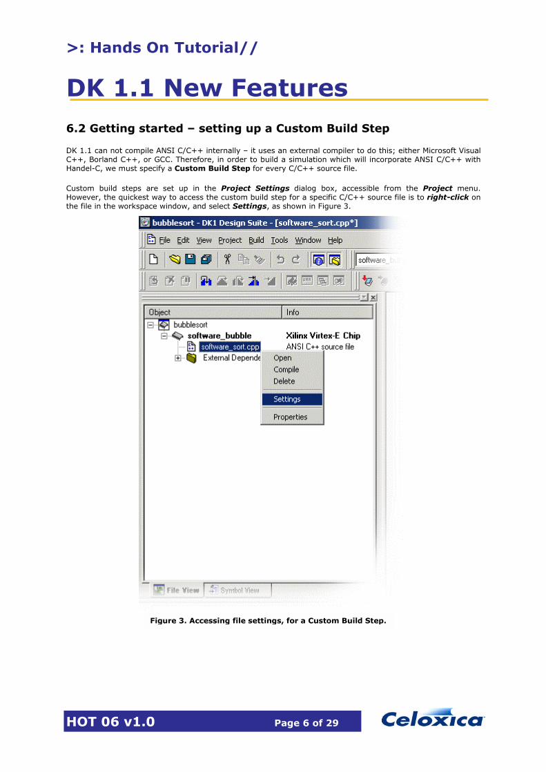
Custom build steps are set up in the Project Settings dialog box, accessible from the Project menu. However, the quickest way to access the custom build step for a specific C/C++ source file is to right-click on the file in the workspace window, and select Settings, as shown in Figure 3.
Figure 3. Accessing file settings, for a Custom Build Step.

>: Hands On Tutorial//
DK 1.1 New Features
HOT 06 v1.0 Page 7 of 29
A custom build step can issue any command, to run an external tool, copy files, etc. The most common use, however, will be to compile a C/C++ source file for use in simulation, so this is what we will use as an example. After open the settings for the C/++ source file, as described above, click on the Build Commands tab, make sure that the View drop-down list is set to Commands, and click the button to create a new command, as shown in Figure 4.
We can now enter the command required to use a backend C/C++ compiler to build the Source file for simulation. If MS Visual C++ is being used, the command is:
The tool, cl in this case, could be replace with one of the other supported C/C++ compilers. The include path must be set to wherever DK 1.1 is installed on your computer � this may be different from the example shown above. In this example, we have used the $(InputName) macro to specify the source file. DK 1.1 will substitute the name of the source file for this macro when it executes the command, but it will not substitute an extension, which is why we have added .cpp after the macro. The /Fo setting for cl allows us to specify where the output object file will be written. In this example, we have used another macro, $(TargetDir), which will be substituted with Debug or Release, depending on which configuration is active. By using these macros, we can now re-use this build command with any C++ source file. A similar command could be used for C files, simply by changing the source extension from .c to .cpp.
Figure 4. Creating a new Build Command, for a custom build step.
New Command button
cl /I C:\Progra~1\Celoxica\DK1\Sim\Include /c $(InputName).cpp /Fo$(TargetDir)\$(InputName).obj
cl � backend compiler
/I� - include path
/c �.cpp �source file
/o �.cpp � output object file
>: Hands On Tutorial//
DK 1.1 New Features
HOT 06 v1.0 Page 8 of 29
Having specified a build command, we must also specify the output resulting from its execution, as DK 1.1 will check the timestamp on this output to see if the build step needs to be executed. Still in the settings for the C/C++ source file, select Outputs from the View drop-down list, and click the New button again. The output should be the same as that specified in the actual build command, in this case:
$(TargetDir)\$(InputName).obj
Again, we use the macro names so that the same output definition can be used for any C/C++ source file. Note that you must specify an output for the build step, or it will nor be executed. DK 1.1 will warn you of this.
6.3 Calling external C/C++ functions from Handel-C
Having created a C++ source file, and specified a custom build step for it, we can now create a Handel-C source file, and call the external C++ functions from it.
Click the New button (or select File->New), select Handel-C Source File, and enter the file name as main. This will create a file called main.hcc, and add it to the project.
All Handel-C programs require a clock to be specified, so we add the line set clock = external; at the start of main.hcc. As we are going to be calling the C++ functions in sotware_sort.cpp, we must declare them as external functions in the Handel-C file, as shown below:
extern "C++"{
void sw_init_data(unsigned char *data, unsigned int n);void sw_print_data(unsigned char *data, unsigned int n);void sw_sort_data(unsigned char *data, unsigned int n);
}
We also require a main() function, from which we will call the C++ functions, and an array of width char, which will contain the list to be sorted, as shown below.
void main(void){
unsigned char data[8];
delay;sw_init_data(&data[0], 8);delay;sw_sort_data( &data[0], 8);delay;sw_print_data(&data[0], 8);delay;
}
The simulator will execute the C++ functions in zero clock cycles, so we insert single-cycle delay; statements between the calls to the functions, to allow us to step through the code in the simulator and observe its operation.
>: Hands On Tutorial//
DK 1.1 New Features
HOT 06 v1.0 Page 9 of 29
6.3.1 Linking in C/C++ modules
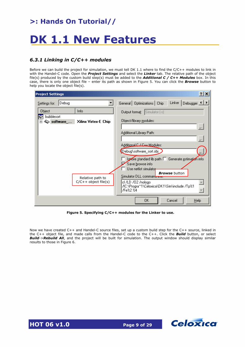
Before we can build the project for simulation, we must tell DK 1.1 where to find the C/C++ modules to link in with the Handel-C code. Open the Project Settings and select the Linker tab. The relative path of the object file(s) produced by the custom build step(s) must be added to the Additional C / C++ Modules box. In this case, there is only one object file � enter its path as shown in Figure 5. You can click the Browse button to help you locate the object file(s).
Now we have created C++ and Handel-C source files, set up a custom build step for the C++ source, linked in the C++ object file, and made calls from the Handel-C code to the C++. Click the Build button, or select Build->Rebuild All, and the project will be built for simulation. The output window should display similar results to those in Figure 6.
Figure 5. Specifying C/C++ modules for the Linker to use.
Browse button Relative path to
C/C++ object file(s)

>: Hands On Tutorial//
DK 1.1 New Features
HOT 06 v1.0 Page 10 of 29
6.3.2 Simulating the Bubblesort
Now the bubblesort project has been successfully built, we can run it in the simulator. Start the simulator either by clicking the Step Into button, selecting Step Into from the Build->Debug menu, or pressing the F11 key. Make sure the Clocks/Threads and Variables windows are displayed (select them from the menu: View->Debug Windows), and the Locals tab in the Variables window is selected. Expand the data array in the Variables window, as shown in Figure 7.
Step through the simulation, one cycle at a time (press F11 to do this). The calls to the C++ functions will be executed in zero clock cycles, and the simulator will only stop on the delay; statements. Each time the simulator stops, you will see the contents of the data array change in the Variables window. The sw_init_data() function uses a random number generator to initialise the array, so the contents of data will be different each time the simulation is executed. After stepping past the call to sw_init_data(), the Variables window should look similar to Figure 8, and after the call to sw_sort_data(), similar to Figure 9. It can be seen that the C++ functions have randomly initialised the array, and then sorted its contents in descending order.
Figure 6. Build output, for main.hcc and software_sort.cpp

>: Hands On Tutorial//
DK 1.1 New Features
HOT 06 v1.0 Page 11 of 29
Figure 7. Debug Simulation of software bubblesort
Figure 9. Array after call to sw_sort_data() for bubblesort.
Figure 8. Array after call to sw_init_data() for initialisation.

>: Hands On Tutorial//
DK 1.1 New Features
HOT 06 v1.0 Page 12 of 29
6.3.3 Inline calls to C/C++ library functions
Start the software_bubble project in simulation again. Note that when the simulator starts, a command window appears, in which standard I/O from the simulation is displayed. Step the simulator until the sw_init_data() function has been executed, and switch to the command window, which should look similar to Figure 10.
The output being displayed in Figure 10 is generated by the C++ functions we have called. It is also possible to use standard C functions like printf() directly in the Handel-C code, if we declare these functions as extern“C” in the Handel-C file from which they are called. A single function, printf() for example, can be declared as shown below:
extern "C" int printf(char *fmt, ... );
Alternatively, it is possible to include an entire library:
extern "C"{#define __cdecl#include <stdio.h>}
Try using the first method in the software_bubble project, declaring printf() on its own, and add some calls to it to provide more information during simulation, e.g.
printf("\nInitialising array\n\n");sw_init_data(&data[0], 8);
delay;
printf("Sorting array...\n");sw_sort_data(&data[0], 8);printf("Sorting complete\n");
Figure 10. Standard I/O output from bubblesort

>: Hands On Tutorial//
DK 1.1 New Features
HOT 06 v1.0 Page 13 of 29
>: 7 Bubblesort in hardware
Create a new project in the bubblesort workspace, called hardware_bubble, selecting the chip type to be Virtex-E. Open Explorer, and copy the files main.hcc and software_sort.cpp from the software_bubble project folder into the hardware_bubble folder. In DK 1.1, right-click on the hardware_bubble project, and select Add Files to Folder, as shown in Figure 11. Select the filter to Handel-C Files, and add main.hcc. Select Add Files to Folder again, and this time set the filter to ANSI C / C++ Files, and add software_sort.cpp to the project. Make sure that you are adding files from the correct folder, i.e. hardware_bubble, not software_bubble!
Before going any further, we need to set up the custom build step again for software_sort.cpp. This can be done easily by copying and pasting the settings from the file in the software_bubble project into this one. Don�t forget to add the object file in the Linker tab for the project as well.
Figure 11. Adding files to a project.

>: Hands On Tutorial//
DK 1.1 New Features
HOT 06 v1.0 Page 14 of 29
7.1 Porting the bubblesort to hardware
Create a new Handel-C file in the hardware_bubble project, called it hardware_sort. In the New File dialog box, be careful to specify the folder where the file will be created, as shown in Figure 12. In this case, it should be in the hardware_bubble folder.
Copy the sw_sort_data() function from software_sort.cpp, and paste it into hardware_sort.hcc, renaming it to hw_sort_data(). In hw_sort_data(), there is an if() statement without an else case, which is not good practice in Handel-C, so the code should be modified as shown below:
void hw_sort_data(unsigned char *data, unsigned int n){
unsigned int i, j;unsigned int temp;for(i=0; i<n-1; i++){
for(j=i+1; j<n; j++){
if(data[i] < data[j]){
temp = data[i];data[i] = data[j];data[j] = temp;
}else
delay;}
}}
Figure 12. Adding a new source file � check specified Location
Check the Location is correctly set

>: Hands On Tutorial//
DK 1.1 New Features
HOT 06 v1.0 Page 15 of 29
Before we can call the hw_sort_data() function from our Handel-C program, we must declare it as an external function in main.hcc, as shown below:
extern void hw_sort_data(unsigned char *data, unsigned int n);
Then, we can replace the call to sw_sort_data() with a call to hw_sort_data(). Note that we now need to cast the length of the list to a specific bit-width, to allow DK 1.1 to infer the widths of other variables in the hw_sort_data() function, as shown below:
hw_sort_data( &data[0], (unsigned 4)8);
The project can now be compiled for debug and executed as before. You may find it useful to set breakpoints on the delay; statements before and after the call to hw_sort_data(), and view the simulation output in the command window.
>: 8 Handling non-standard data widths in C++
Create a new project in the bubblesort workspace, called bubble_wide, selecting the chip type to be Virtex-E. Open Explorer, and copy the files main.hcc, hardware_sort.hcc and software_sort.cpp from the hardware_bubble project folder into the bubble_wide folder. In DK 1.1, right-click on the bubble_wide project, and select Add Files to Folder. Select the filter to Handel-C Files, and add main.hcc and hardware_sort.hcc. Select Add Files to Folder again, and this time set the filter to ANSI C / C++ Files, and add software_sort.cpp to the project. Make sure that you are adding files from the correct folder, i.e. bubble_wide. Set up the custom build step for software_sort.cpp.
The first two versions of the bubblesort have used 8-bit wide data (type char), which is a standard C++ data type. We will now change the Handel-C code to use data of a different width, and modify the C++ code to handle this. Open hardware_sort.hcc in the bubble_wide project, and change the type for the pointer to data from char to 12-bit:
void hw_sort_data(unsigned 12 *data, unsigned int n){...
Open main.hcc, change the type of the data array to 12-bit, and also update the extern prototype for hw_sort_data() to reflect the change from char to 12-bit data. We are now ready to modify the C++ code to handle the 12-bit data being used by the Handel-C code.
8.1 Setting up software to use the Wide Number Library
Support for non-standard data widths in C++ is provided through the Wide Number Library, which is supplied with DK 1.1. Extensive documentation on the library can be found in the on-line help, but in this tutorial we will cover just a few examples of its use.
To set up a C++ file to use the Wide Number Library, we must add the following lines of code at the head of the file (in this case, to software_sort.cpp):
#include <hcnum.h>using namespace HCNum;
The file hcnum.h is located in the include directory in the DK 1.1 installation. We specified this as an include directory in the custom build step for the C++ file. Having added these lines of code, we can now proceed to use the library to support non-standard data widths.

>: Hands On Tutorial//
DK 1.1 New Features
HOT 06 v1.0 Page 16 of 29
8.2 Non-standard types for C++ parameters and variables
The first task in modifying the C++ code to handle non-standard data widths is to change the types of the function parameters and any variables which will be used. The Wide Number Library provides two classes, called Int and UInt, which can be used to declare variables and parameters of any width, e.g.
Int<3> Temp1; //declare a variable Temp1, type 3-bit signedUInt<12> Temp2; //declare a variable Temp2, type 12-bit unsigned
So, we must modify the functions in software_sort.cpp to handle unsigned 12-bit parameters, as that is what we have used in the Handel-C code:
void sw_init_data( UInt<12> *data, unsigned int n ){...
The prototypes in main.hcc must be updated accordingly, but can not use the Int and UInt classes, as they are only for C++ code, and not for Handel-C. So, the prototypes for the modified C++ functions appear as shown below:
extern "C++"{
void sw_init_data(unsigned 12 *data, unsigned int n);void sw_print_data(unsigned 12 *data, unsigned int n);void sw_sort_data(unsigned 12 *data, unsigned int n);
}
Variables of type UInt or Int can also be declared and used in C++ code. All normal arithmetic operators are overloaded to handle the classes, so most code can remain unmodified. The only required modification in the C++ code for this tutorial is the type of the temp variable in sw_sort_data(), which must be changed to:
UInt<12> temp;
8.3 Casting from a C++ type to a Handel-C data type
Having changed the types of the C++ function parameters, we must now cast data to the correct type inside these functions. The only function in software_sort.cpp which requires this modification is sw_init_data(), which requires the line:
data[i] = (unsigned char)(rand()%256);
To be changed to:
data[i] = (UInt<12>)(rand()%4096);
Note that we have also changed the modulus expression, as an unsigned 12-bit number can hold values up to 4096, compared to 256 for the unsigned char.

>: Hands On Tutorial//
DK 1.1 New Features
HOT 06 v1.0 Page 17 of 29
8.4 Converting a Handel-C data type to a C++ type
The Wide Number Library provides four methods to convert from a Handel-C data type to a C++ data type, allowing for conversion to signed and unsigned integers, of 32 or 64-bit width. In this tutorial we are only using the method to convert to convert to an unsigned 32-bit integer. For more detail on the other methods, and the range of other functions which are supported, refer to the on-line help.
The only cases in our bubblesort C++ functions which need conversion of this type are where a value from the data array is used as a parameter in printf(). We must change the line:
printf("ARRAY[%d] = %d\n", i, data[i].);
to:
printf("ARRAY[%d] = %d\n", i, data[i].UIntOf());
thereby using UintOf() to convert form the 12-bit unsigned data into a 32-bit unsigned integer, which can then be handled correctly by the printf() function.
The project can now be compiled for Debug and simulated. The output in the command window can be seen to relate to unsigned 12-bit data, rather than the 8-bit data in use previously.
>: 9 Generation of automated functional testbenches
The current version of the bubblesort project simply displays the sorted data in the command window, allowing the user to visually inspect that the operation was correct. However, in many applications this will not be possible. We will now create an automated testbench to prove the functionality of the Handel-C code, compared to the C++ version.
Create a new project in the bubblesort workspace, called bubble_testbench, selecting the chip type to be Virtex-E. Open Explorer, and copy the files main.hcc, hardware_sort.hcc and software_sort.cpp from the hardware_bubble project folder into the bubble_testbench folder. Do not use the files from the bubble_wide project. In DK 1.1, right-click on the bubble_testbench project, and select Add Files to Folder. Select the filter to Handel-C Files, and add main.hcc and hardware_sort.hcc. Select Add Files to Folder again, and this time set the filter to ANSI C / C++ Files, and add software_sort.cpp to the project. Make sure that you are adding files from the correct folder, i.e. bubble_testbench. Set up the custom build step for software_sort.cpp.
Modify the main.hcc file to contain 2 copies of the data array, and after initialising one, copy its contents into the other, and then call both the Handel-C and C++ bubblesort functions, passing the copy of data into the C++ version:
unsigned char data[8], data_copy[8];
sw_init_data(data, 8);
par(i=0;i<8;i++) // Copy the data from one array to the other{
data_copy[i] = data[i];}
hw_sort_data(data, (unsigned 4)8);sw_sort_data(data_copy, 8);

>: Hands On Tutorial//
DK 1.1 New Features
HOT 06 v1.0 Page 18 of 29
Now we need to write a C++ function to compare the results of the two different bubblesort functions. This can be put inside the software_sort.cpp source file. An example of how this could be written is shown below:
void sw_compare_data(unsigned char *data1, unsigned char *data2, unsigned int n){
unsigned int i;unsigned int errors=0;
printf("\nComparing results...\n\n" ) ;for(i=0;i<n;i++){
if(data1[i] != data2[i]){
printf("error in array[%d] : ",i);printf("Hardware = %d, Software = %d\n",data1[i],data2[i]);errors++;
}}
if(errors!=0)printf("\n %d errors found.\n", errors);
elseprintf("\nNo errors.\n");
}
Add this function to software_sort.cpp, an extern prototype in main.hcc, then call the function after hw_sort_data() and sw_sort_data(), to compare the results of the two. If the Handel-C code has been written correctly, the compare function should report no errors. Just to check that it does in fact detect errors, try �breaking� the Handel-C code in hw_sort_data(), by changing some of the for() loop control parameters. Remember that the data array is initialised randomly every time the simulation is executed, so there may sometimes be no errors, even with the �broken� Handel-C code.
>: Hands On Tutorial//
DK 1.1 New Features
HOT 06 v1.0 Page 19 of 29
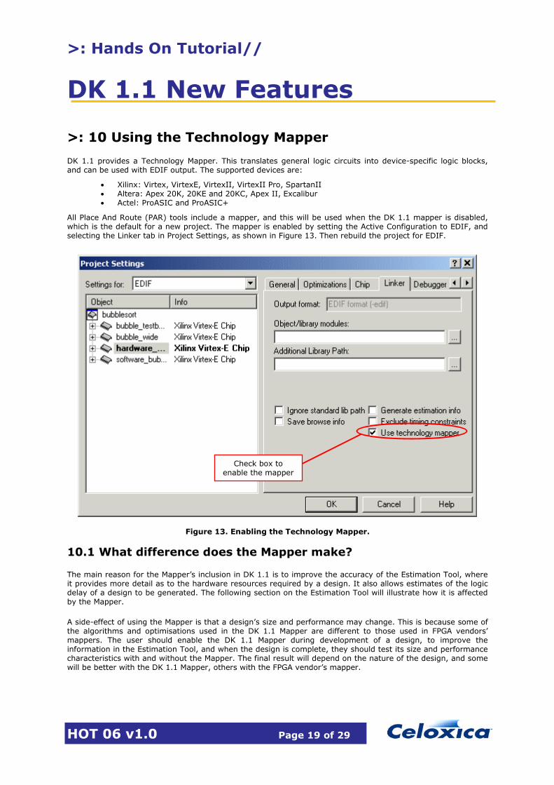
>: 10 Using the Technology Mapper
DK 1.1 provides a Technology Mapper. This translates general logic circuits into device-specific logic blocks, and can be used with EDIF output. The supported devices are:
• Xilinx: Virtex, VirtexE, VirtexII, VirtexII Pro, SpartanII • Altera: Apex 20K, 20KE and 20KC, Apex II, Excalibur • Actel: ProASIC and ProASIC+
All Place And Route (PAR) tools include a mapper, and this will be used when the DK 1.1 mapper is disabled, which is the default for a new project. The mapper is enabled by setting the Active Configuration to EDIF, and selecting the Linker tab in Project Settings, as shown in Figure 13. Then rebuild the project for EDIF.
10.1 What difference does the Mapper make?
The main reason for the Mapper�s inclusion in DK 1.1 is to improve the accuracy of the Estimation Tool, where it provides more detail as to the hardware resources required by a design. It also allows estimates of the logic delay of a design to be generated. The following section on the Estimation Tool will illustrate how it is affected by the Mapper.
A side-effect of using the Mapper is that a design�s size and performance may change. This is because some of the algorithms and optimisations used in the DK 1.1 Mapper are different to those used in FPGA vendors� mappers. The user should enable the DK 1.1 Mapper during development of a design, to improve the information in the Estimation Tool, and when the design is complete, they should test its size and performance characteristics with and without the Mapper. The final result will depend on the nature of the design, and some will be better with the DK 1.1 Mapper, others with the FPGA vendor�s mapper.
Figure 13. Enabling the Technology Mapper.
Check box to enable the mapper

>: Hands On Tutorial//
DK 1.1 New Features
HOT 06 v1.0 Page 20 of 29
>: 11 Using the DK 1.1 Estimation Tool
DK 1.1 includes a new delay and area Estimation Tool, which allows the user to identify which portions of their code are taking up more hardware resources, or incurring a higher logic delay. The Estimation Tool output is in HTML format, and can be viewed using a standard web browser. In the following sections we will make some basic improvements to the Handel-C bubblesort, and set it up for EDIF compilation, then illustrate the use of the Estimation Tool with it.
11.1 Further modifications to Handel-C bubblesort
Create a new project in the bubblesort workspace, called hardware_bubble2, selecting the chip type to be Virtex-E. Open Explorer, and copy the files main.hcc, hardware_sort.hcc and software_sort.cpp from the hardware_bubble project folder into the hardware_bubble2 folder. In DK 1.1, right-click on the hardware_bubble2 project, and select Add Files to Folder. Select the filter to Handel-C Files, and add main.hcc and hardware_sort.hcc. Select Add Files to Folder again, and this time set the filter to ANSI C / C++ Files, and add software_sort.cpp to the project. Make sure that you are adding files from the correct folder, i.e. hardware_bubble2. Set up the custom build step for software_sort.cpp.
We will now modify the Handel-C bubblesort so it can be compiled successfully for EDIF, and also make some basic optimisations to the code. First, we will modify the hw_sort_data() function. Functions are sometimes less efficient in Handel-C than macro procedures, so we will convert hw_sort_data() to a macro proc, which also allows us to parameterise it to accept arrays of any size and data width. We will also change the for() loops into do…while(), as these are more efficient in Handel-C, and add some par{} statements. The modified Handel-C bubblesort is shown below:
#include <stdlib.hch>macro proc hw_sort_data(data, n){
macro expr AddrBits = (log2ceil(n));static unsigned (AddrBits+1) i=0,j=1;while(i < (n-1)){
while(j < n){
par{
if(data[i<-AddrBits] < data[j<-AddrBits]){
par{
data[j<-AddrBits] = data[i<-AddrBits];data[i<-AddrBits] = data[j<-AddrBits];
}}else
delay;j++;
}}par{
i++;j=i+2;
}}
}
Note that we have included the Handel-C standard library header (stdlib.hch), so we must also add stdlib.hcl into the Object/library modules box on the Linker tab of the Project Settings.

>: Hands On Tutorial//
DK 1.1 New Features
HOT 06 v1.0 Page 21 of 29
In order to compile the Handel-C bubblesort for EDIF, we must create input and output interfaces, and use them in the design. The following procedures copy data in and out of the array used by the bubblesort:
unsigned char Output;interface bus_out() OutBus(Output);interface bus_clock_in(unsigned char) InBus();
macro proc hw_init_data(data, n){
macro expr AddrBits = (log2ceil(n));static unsigned (AddrBits+1) i=0;do{
par{
data[i<-AddrBits] = InBus.in;i++;
}}while(i < n);
}
macro proc hw_print_data(data, n){
macro expr AddrBits = (log2ceil(n));static unsigned (AddrBits+1) i=0;do{
par{
Output = data[i<-AddrBits];i++;
}}while(i < n);
}
We must also modify main.hcc, as the C++ functions can not be included when compiling for EDIF. We can use #ifdef statements to do this, as shown below:
set clock = external;#ifdef SIMULATEextern "C++"{
void sw_init_data(unsigned char *data, unsigned int n);void sw_print_data(unsigned char *data, unsigned int n);void sw_sort_data(unsigned char *data, unsigned int n);
}#endif
extern macro proc hw_sort_data(data, n);extern macro proc hw_init_data(data, n);extern macro proc hw_print_data(data, n);
void main(void){
unsigned char data[8];#ifdef SIMULATE
sw_init_data(data, 8);hw_sort_data(data, (unsigned 4)8);sw_print_data(data, 8);
#elsehw_init_data(data, (unsigned 4)8);hw_sort_data(data, (unsigned 4)8);hw_print_data(data, (unsigned 4)8);
#endif}
We can now set the Active Configuration to EDIF and rebuild the design. Do not worry about the warnings concerning unconstrained pins, as we are not actually going to download this design into a physical device.

>: Hands On Tutorial//
DK 1.1 New Features
HOT 06 v1.0 Page 22 of 29
11.2 Enabling the Estimation Tool, and viewing its output
The Estimation Tool is enabled on the Linker tab of Project Settings, as shown in Figure 14. If we now rebuild, the Estimation Tool will generate estimation information for the design.
Figure 14. Enabling the Estimation Tool
Check box to enable the Estimation Tool
Make sure Configuration is set to EDIF

>: Hands On Tutorial//
DK 1.1 New Features
HOT 06 v1.0 Page 23 of 29
After rebuilding the design, open Explorer and browse into the EDIF directory, where you will see a file named Summary.html, which contains a summary of the design, generated by the estimation tool. Figure 15 shows the summary file, with explanations. The summary includes estimates of the area used by each file in the project, and also the longest paths in terms of the number of logic levels. Clicking on the links will take you to more detailed information.
Click links to go to detailed area estimation
Figure 15. Estimation Tool summary file
Click link to go to detailed delay estimation
Delay Summary, in logic levels
Area Summary

>: Hands On Tutorial//
DK 1.1 New Features
HOT 06 v1.0 Page 24 of 29
Figure 16 shows part of the detailed area estimation for the hardware_sort.hcc file. The area usage from the summary page is broken down to individual lines here, indicating how many NAND gates, FFs and memory bits are used by each line of code. The colouring of the code indicates the distribution of these resources across each line.
Figure 16. Detailed area estimation information.
Resources used by this line of code
Colouring indicates distribution of resources

>: Hands On Tutorial//
DK 1.1 New Features
HOT 06 v1.0 Page 25 of 29
Figure 17 shows the detailed delay estimation for the longest path from FF to FF. Clicking on the links in the left panel of the page will cause the right panel to jump to the associated line of code. The left panel clearly indicates how many logic levels are associated with each line of code, allowing the user to focus on the �slowest� line of code first when optimising the design.
Figure 17. Detailed delay estimation information
Click links to jump to line numbers

>: Hands On Tutorial//
DK 1.1 New Features
HOT 06 v1.0 Page 26 of 29
11.3 Using the Estimation Tool with the Mapper
If the DK 1.1 Technology Mapper is turned on, the Estimation Tool can produce more accurate information. Figure 18 shows how the Summary Page appears when the Mapper is turned on. The area estimation still includes FFs and memory bits, but the NAND gates have now been split into LUTs (Look-Up Tables) and other components. The �other� section includes multiplexers, fast carry chains and other device-specific components. The summary of the longest paths now describes them in terms of the delay in nanoseconds, rather than logic levels. This is possible because the mapper has translated the design into specific components, for which the logic delays are known in advance. Note that this estimate does not make any allowance for routing delay, as this information is only available after PAR using the FPGA vendor�s tools. Reducing the logic delay of a design will increase its performance, but the actual minimum clock period will always be higher than the estimated path delay, after the routing delay has been taken account of.
The detailed area and delay information is also enhanced with the information from the Mapper, listing the usage of hardware resources, and including the logic delay in nanoseconds per component in the longest paths.
Area Summary after mapping
Estimated Logic Delay after mapping
Figure 18. Estimation Summary, using Technology Mapper

>: Hands On Tutorial//
DK 1.1 New Features
HOT 06 v1.0 Page 27 of 29
11.4 Using the Estimation Tool output
Most users will be aiming to increase the performance of their design using the estimation tool. The procedure to follow in this case is simple:
1. Set Active Configuration to EDIF. Enable the Technology Mapper and Estimation Tool.
2. Rebuild the project.
3. Open the estimation summary and click the link for the longest path info.
4. On the longest path, jump to the source code line or lines which have the largest number of components associated with them.
5. Return to the Handel-C source in DK 1.1, and modify the line(s) of code identified by the Estimation Tool.
6. Rebuild the project, and return to the estimation summary page, to see what the effect was.
The longest path will usually be from FFs to FFs, but the delays to and from the pins should be checked as well, in case they are limiting the performance of the design. Typical optimisations which might be made, having identified the offending lines of code, include:
• Changing comparison operators (>, <, >=, <=) to equality tests (==, !=).
• Pipelining a portion of code, by splitting a complex operation into 2 or more stages.
• Reducing the bit-width of variables used in loop control.
• Avoid variable indices for arrays where possible.
• Convert deeply nested if()…else statements to an alternative program structure.
• Register address and data for any RAM access.
Other users may wish to optimise the area of the design, thereby reducing the size of the device required to implement it. The procedure is similar, expect this time the user should use the estimation summary to identify which of the source files are contributing most to the area of the design, and focus on optimising these first. Scrolling down the detailed area information for each source file will quickly reveal which lines of code are contributing most to the design size. Many of the optimisations which are listed above for reducing the delay will also reduce the area; some others apply specifically to area reduction:
• Moving arrays in RAM structures.
• Moving large distributed RAMs into Block RAM (Xilinx devices).
• Reducing the complexity of arithmetic, e.g. avoiding large multipliers.
After modifying the source code, rebuild the project to see what difference the changes made. In the following section we will use the Estimation Tool with the bubblesort program.

>: Hands On Tutorial//
DK 1.1 New Features
HOT 06 v1.0 Page 28 of 29
>: 12 Optimising bubblesort using the Estimation Tool
We will optimise the Handel-C bubblesort using the Estimation Tool. The focus will initially be on reducing the area of the design, and then on reducing the delay on the longest paths. While doing this, we will attempt to avoid reducing the overall performance too much.
Create a new project in the bubblesort workspace, called hardware_bubble3, selecting the chip type to be Virtex-E. Open Explorer, and copy the files main.hcc, hardware_sort.hcc and software_sort.cpp from the hardware_bubble2 project folder into the hardware_bubble3 folder. In DK 1.1, right-click on the hardware_bubble3 project, and select Add Files to Folder. Select the filter to Handel-C Files, and add main.hcc and hardware_sort.hcc. Select Add Files to Folder again, and this time set the filter to ANSI C / C++ Files, and add software_sort.cpp to the project. Make sure that you are adding files from the correct folder, i.e. hardware_bubble3. Set up the custom build step for software_sort.cpp.
By creating a new project, we can compare it to the previous version, to see what improvements in area and delay we can achieve. The following sections are for you to attempt, using the information given so far. Solutions will be made available later.
12.1 Reducing area
Build the project with the Technology Mapper and the Estimation Tool enabled, open the estimation summary HTML file, and browse to the detailed area information for both of the source files. A quick glance over the estimation information should reveal that the declaration of the data array and the accesses to it are contributing most to the total area of the design. Try to reduce the area by storing the data in RAM instead.
Hints: A RAM can only be accessed once per clock cycle, so watch out for par{} statements. Remember to register the data coming out of the RAM � don�t use it directly in an if() statement.
12.2 Reducing delay and increasing performance
By using a RAM to store the data to be sorted, the bubblesort will now take many more cycles to execute. This can be reduced by using a multi-port RAM (mpram), with one read port and one read/write port. This will allow some parallel accesses to be made to the RAM, reducing the number of cycles required to complete the bubblesort. Try using a Block RAM to store the data, and see what difference this makes. Look for any comparison operators in the bubblesort procedure, and replace them with inequality tests, to see if the delay can be reduced.
Hints: Using a Block RAM for a small memory like this is wasteful, as an entire block will be used for only a small amount of data, but try it anyway to see what the result is. When using a multi-port RAM, try and spread the number of read accesses evenly across the two ports.
12.3 Area/delay/performance tradeoffs
In these recent sections you will have seen how the Estimation Tool can allow you to make more informed decisions about the architecture and implementation of your design. In most cases the size and performance of a design can be traded off against each other by making simple changes to the source code. Remember that the information from the Estimation Tool does not take account of routing delays � if you have time, try running a Place And Route on the last two bubblesort projects, to see what the actual results are. If you do this, remember to add a rate specification to the clock definition in main.hcc, so the PAR tools have a target clock rate to aim for.

>: Hands On Tutorial//
DK 1.1 New Features
HOT 06 v1.0 Page 29 of 29
>: 13 Further Information
For information on Celoxica products contact [email protected]. Regional office locations are given below.
Customer Support at [email protected] and +44 (0)1344 663649.
Celoxica Ltd.
20 Park Gate
Milton Park
Abingdon
Oxfordshire OX14 4SH
United Kingdom
Tel: +44 (0) 1235 863 656
Fax: +44 (0) 1235 863 648
Celoxica, Inc
900 East Hamilton Avenue
Campbell, CA 95008
USA
Tel: +1 800 570 7004
Tel: +1 408 626 9070
Fax: +1 408 626 9079
Celoxica Japan KK
YBP West Tower 11F
134 Godo-cho, Hodogaya-ku
Yokohama 240-0005
Japan
Tel: +81 (0) 45 331 0218
Fax: +81 (0) 45 331 0433
Celoxica Pte Ltd
Unit #05-03
31 Int�l Business Park
Singapore
609921
Tel: (65) 6896 4838
Fax: (65) 6566 9213
Copyright © 2002 Celoxica Ltd. All rights reserved. Celoxica, the Celoxica logo and �cutting a LONG story SHORT� are trademarks of Celoxica Ltd.
www.celoxica.com


![PDF] Hands-On Tutorial on Ab Initio Molecular Simulations ...Hands-On Tutorial on Ab Initio Molecular Simulations Berlin, July 12 { 21, 2011 Tutorial I: Basics of Electronic-Structure](https://static.fdocuments.us/doc/165x107/612d24fa1ecc5158694201ae/hands-on-tutorial-on-ab-initio-molecular-simulations-hands-on-tutorial-on-ab.jpg)