DIY Bluetooth Gamepad - Adafruit Industries Bluetooth Gamepad Created by Ruiz Brothers Last updated...
54
DIY Bluetooth Gamepad Created by Ruiz Brothers Last updated on 2016-09-03 02:23:21 AM UTC
-
Upload
hoangkhanh -
Category
Documents
-
view
220 -
download
2
Transcript of DIY Bluetooth Gamepad - Adafruit Industries Bluetooth Gamepad Created by Ruiz Brothers Last updated...

DIY Bluetooth GamepadCreated by Ruiz Brothers
Last updated on 2016-09-03 02:23:21 AM UTC

244567
8111112
13131415161718192021
22222324252627
282830313233
343435
Guide Contents
Guide ContentsOverview
Prerequisite GuidesExpectationsPartsTools & Supplies
Circuit Diagram3D Printing
Parts & SettingsPrinting Parts
Power CircuitPrep Slide Switch WiresSolder Wires to Slide switch500mAh Charging RateWire Slide Switch to Lipo Charger & Bluefruit EZ-KeyPrep Ground WireWire Ground to Micro USB Lipo ChargerWire Ground to Bluefruit EZ-KeyWired Power CircuitTest Power Circuit
Button LayoutPrep Perma-Proto Half-size PCBInstall tactile buttonsInstalled buttonsSolder buttons to Perma-ProtoSaw bottom corners from Perma-Proto PCBTrimmed Perma-Proto PCB
Wiring Buttons GroundPrep Ground WiresGround WiresButton Ground PlacementSolder Ground WiresSoldered Ground Wires
Wiring Buttons InputWire Perma-Proto PCB ground to Bluefruit EZ-Key groundWire Buttons to EZ-Key Inputs
© Adafruit Industries https://learn.adafruit.com/diy-bluetooth-gamepad Page 2 of 53

36373839
4040414243444546474848505151525353
Wired Buttons to Bluefruit EZ-KeyWire BlueTooth Pair button to EZ-KeySoldered Inputs to Bluefruit EZ-KeyHeat Shrink Input Wires
AssemblyAdd screws to bottom coverMount Micro USB Lipo Charger to bottom coverMount Bluefruit EZ-Key to bottom coverMount Bluefruit EZ-Key to bottom coverMount Bluetooth Pair button to bottom coverPlug in 500mAh Lithium Polymer BatteryMount Perma-Proto to bottom coverInsert 500mAh batteryInstall Ninjaflex buttons into caseInsert circuit into caseInstall slide switch into caseFasten bottom cover to caseAdd cover to top caseCharge Battery and Play!Changing Button MappingPairing with Devices
© Adafruit Industries https://learn.adafruit.com/diy-bluetooth-gamepad Page 3 of 53

OverviewIn this project we’re building a DIY gamepad using the Bluefruit EZ-Key module and a 3Dprinted case.
The Bluefruit EZ-Key HID keyboard controller is a bluetooth breakout design for makingDIY keyboards and game pads. It’s requires no programing and works with just about anytrigger or push button. It takes up to 12 inputs and can be powered with any 3-16 VDC.
The Perma-Proto comes in different sizes which is perfect for making all sorts of projects.The ½ sized Perma-Proto breadboard is like a business card and which makes it perfect formaking a small game controller.
Prerequisite Guides
We recommend walking through the guides below - these will help you get familar with thecomponents used in this project.
Introducing EZ-Key Bluefruit (http://adafru.it/rd7)Adafruit Guide to Excelllent Soldering (http://adafru.it/drI)
© Adafruit Industries https://learn.adafruit.com/diy-bluetooth-gamepad Page 4 of 53

Expectations
This is a project that requires a bit of soldering and wiring - It's great for getting practice andwell suited for makers with intermediate soldering skills. It's not the easiest 'first-time'beginners project, but it can be done if approached with patience, ambition and positivity.The 3D printing takes 2-3 hours and costs about $1.50 in material. If you don't have accessto a 3D printer, check with your local hacker/maker space, library or community collage -they just might have one! Have fun, and happy making!
© Adafruit Industries https://learn.adafruit.com/diy-bluetooth-gamepad Page 5 of 53
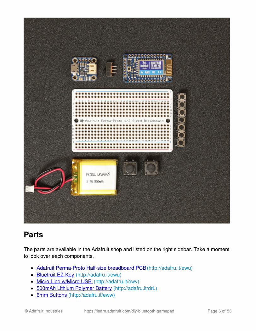
Parts
The parts are available in the Adafruit shop and listed on the right sidebar. Take a momentto look over each components.
Adafruit Perma-Proto Half-size breadboard PCB (http://adafru.it/ewu)Bluefruit EZ-Key (http://adafru.it/ewu)Micro Lipo w/Micro USB (http://adafru.it/ewv)500mAh Lithium Polymer Battery (http://adafru.it/drL)6mm Buttons (http://adafru.it/eww)
© Adafruit Industries https://learn.adafruit.com/diy-bluetooth-gamepad Page 6 of 53

12mm Buttons (http://adafru.it/1119)Slide switch (http://adafru.it/drN)
Tools & Supplies
You'll need some hand tools, a soldering iron, 3D printer, wires and other maker tools andsuppilies.
3D Printer (http://adafru.it/d9z)Soldering Iron (http://adafru.it/doU)Wire cutters (http://adafru.it/152) + strippers (http://adafru.it/527)30AWG Silicone Coated wire (http://adafru.it/2051)PLA (http://adafru.it/2080)+Semiflex (http://adafru.it/2321) filament (3mm/1.75mm)Panavise Jr (http://adafru.it/dDJ). + Helping third hands (http://adafru.it/dxR)Heat Shrink Pack (http://adafru.it/1649)Blue painters tape#4-40 3/8 flat Phillips machine screws
© Adafruit Industries https://learn.adafruit.com/diy-bluetooth-gamepad Page 7 of 53

Circuit Diagram
Take a moment to review the components in the circuit diagram. This illustration is meantfor referencing wired connections - The length of wire, position and size of components arenot exact.
The 500mAh lithium polymer battery is connected to the microUSB lipo charger via JSTcable. The Bluefruit EZ-Key has VIN pin connected to a slide switch. The BAT pin on themicro lipo charger is wired to the slide switch. The ground pin on the Bluefruit EZ-Key iswired to the GND pin on the micro lipo charger.
A 6mm tactile switch is wired to pins 3V and PB on the Bluefruit EZ-Key to serve as abluetooth pair button.
The 6mm and 12mm tactile button inputs are wired to input pins 0-7 on the Bluefruit EZ-Key. Each tactile button has ground connected to ground rails on the Perma-Proto PCB.
© Adafruit Industries https://learn.adafruit.com/diy-bluetooth-gamepad Page 8 of 53

The 1/2 sized Perma-proto breadboard PCB will house the 8 momentary push buttons. Theright-side of each buttons will act as the ground connection. Each of the buttons rightterminal are wired to the ground rail. The two ground rails are wired together. A single wirefor the ground connection is wired to the Bluefruit EZ-Key. Each botton left terminal has awired connection to the input pins.
The input connections on the Perma-Proto should preferably be made on the back of thePCB and close-to to terminal, not actually on the same through-hole.
Be very aware and cautious when wiring these connections. It's easy to get lost and looseyour place/spot while soldering. Always double check your connections before you solder!
© Adafruit Industries https://learn.adafruit.com/diy-bluetooth-gamepad Page 9 of 53

© Adafruit Industries https://learn.adafruit.com/diy-bluetooth-gamepad Page 10 of 53

3D Printing
Parts & Settings
permapad-bot.stlpermapad-top.stlpermapad-cover.stl
PLA @22010% infill2 shells.2mm layer height50/40 speeds
Takes about 2 hours and 28 grams ($1.29)
perma-dpad.stlperma-ab-buttons.stlperma-bt.stl
Semiflex orNinjaflexExtruder @2304 top layers Takes about 15 minutes and 3 grams
© Adafruit Industries https://learn.adafruit.com/diy-bluetooth-gamepad Page 11 of 53

perma-start-select.stl 10% infill.2mm layer height2 shells
($0.14)
Thingiverse Downloadhttp://adafru.it/exKYouMagine Downloadhttp://adafru.it/exTCults3D Downloadhttp://adafru.it/exU
Printing Parts
The enclosure parts can be printed in PLA or ABS filament. PLA material tends to haveless warped corners. We printed out the controller buttons in TPE filament, which makesthem flexible and rubbery. No support material is required for the parts.
STLs are oriented to "print-as-is". Our recommend slice settings work well with Printrbotsand Orion delta machines.
© Adafruit Industries https://learn.adafruit.com/diy-bluetooth-gamepad Page 12 of 53

Power Circuit
Prep Slide Switch Wires
Start off by prepairing the wiring for the slide switch. You'll need to measure two pieces of30AWG silicone-coated stranded wires to about 10cm long. Strip both ends of the wiresand apply solder to 'tin' the tips - This helps prevent the stranded wires from coming apart.
© Adafruit Industries https://learn.adafruit.com/diy-bluetooth-gamepad Page 13 of 53

Solder Wires toSlide switch
Secure the slide switch to aPanavise Jr. Secure one wire tothe little grabber on the helpingthird hands with the end of thewire overlapping a terminal onthe slide switch. With the wireand switch secured in place,apply solder to join themtogether. Lightly tug the wireand inspect for a goodconnection. Repeat this processfor the next wire. Add pieces ofheat shrink tubing to insultate theexposed connection.
© Adafruit Industries https://learn.adafruit.com/diy-bluetooth-gamepad Page 14 of 53

Add heat shrink tubing to the teeth of the Third Hand grabbers to safely secure wires. Thishelps prevent kinks in the wires and scratches from components.
500mAh Charging Rate
You'll want to up the charging rate on the Micro Lipo charger. To make it safe for all ourbatteries, we set the default rate to 100mA. You can easy up the charge rate to 500mA by
© Adafruit Industries https://learn.adafruit.com/diy-bluetooth-gamepad Page 15 of 53

connecting the solder jumper . This will allow the 500mAh lithium polymer battery to chargefaster. Melt some solder onto the jumper to close it and set the new charge rate.
Wire Slide Switch to Lipo Charger & Bluefruit EZ-Key
Secure the micro lipo charger PCB to panavise Jr. Apply solder to the BAT and GND pins.Now solder one of the wires from the slide switch to the BAT pin by heating up the pin andinserting the wire while the solder is hot and molten. Repeace this process for the VIN pinon the Bluefruit EZ-Key.
© Adafruit Industries https://learn.adafruit.com/diy-bluetooth-gamepad Page 16 of 53

Prep Ground Wire
We'll need a wire to connect ground to the Micro Lipo charger. Measure and cut a piece of30AWG silicone-coated stranded wire to about 5cm long. Strip and tin both ends of thewire.
© Adafruit Industries https://learn.adafruit.com/diy-bluetooth-gamepad Page 17 of 53

Wire Ground to Micro USB Lipo Charger
Secure the lipo charger PCB to the Panavise jr. Solder the ground wire into the GND pin.Double check connection by tugging on the wire, ensuring a solid connection. Remove fromPanavise jr. when complete.
© Adafruit Industries https://learn.adafruit.com/diy-bluetooth-gamepad Page 18 of 53

Wire Ground to Bluefruit EZ-Key
Secure the Bluefruit EZ-Key to the Panavise jr. Apply solder to the G pin and insert theremaining end of the ground wire while the solder is moltent. Double check connection issolid. Remove from Panavise jr. when complete.
© Adafruit Industries https://learn.adafruit.com/diy-bluetooth-gamepad Page 19 of 53

Wired Power Circuit
Double check your work. The power circuit is now complete! Next step is to plug in the JSTcable from the lithium polymer to the lipo charger.
© Adafruit Industries https://learn.adafruit.com/diy-bluetooth-gamepad Page 20 of 53

Test Power Circuit
Plug in the JST cable from the 500mAh battery to the JST port on the lipo charger. Theslide switch will power on the circuit when the switch is set to the farthest terminal with thewire connection. If the LED lights on the Bluefruit EZ-Key, everything is good!
If the LED doesn't power on, double check your wiring. The battery may be drained, socheck that too!
© Adafruit Industries https://learn.adafruit.com/diy-bluetooth-gamepad Page 21 of 53

Button Layout
Prep Perma-Proto Half-size PCB
In this project, we're using the half-size perma-proto PCB. We'll add the buttons with thePCB oriented with the labels right-side up.
© Adafruit Industries https://learn.adafruit.com/diy-bluetooth-gamepad Page 22 of 53

Install tactilebuttons
Add 6mm buttons to the Perma-Proto by inserting them into placewith the terminals going into thethrough-holes.
If the terminals don't insert all theway, try bending them slightlyuntil they fit into place.
Ensure the oriention of thebuttons are correct - terminalsshould be pointing up/down asopposed to left/right. Polarity willmatter once the ground andinputs are wired.
Two 12mm buttons go on the farright, acting as the "A" and "B"buttons.
© Adafruit Industries https://learn.adafruit.com/diy-bluetooth-gamepad Page 23 of 53

Installed buttons
Double check your buttons are properly oriented and exactly in the right spot! You canfollow the photo and circuit diagram to cross reference the button placement.
© Adafruit Industries https://learn.adafruit.com/diy-bluetooth-gamepad Page 24 of 53
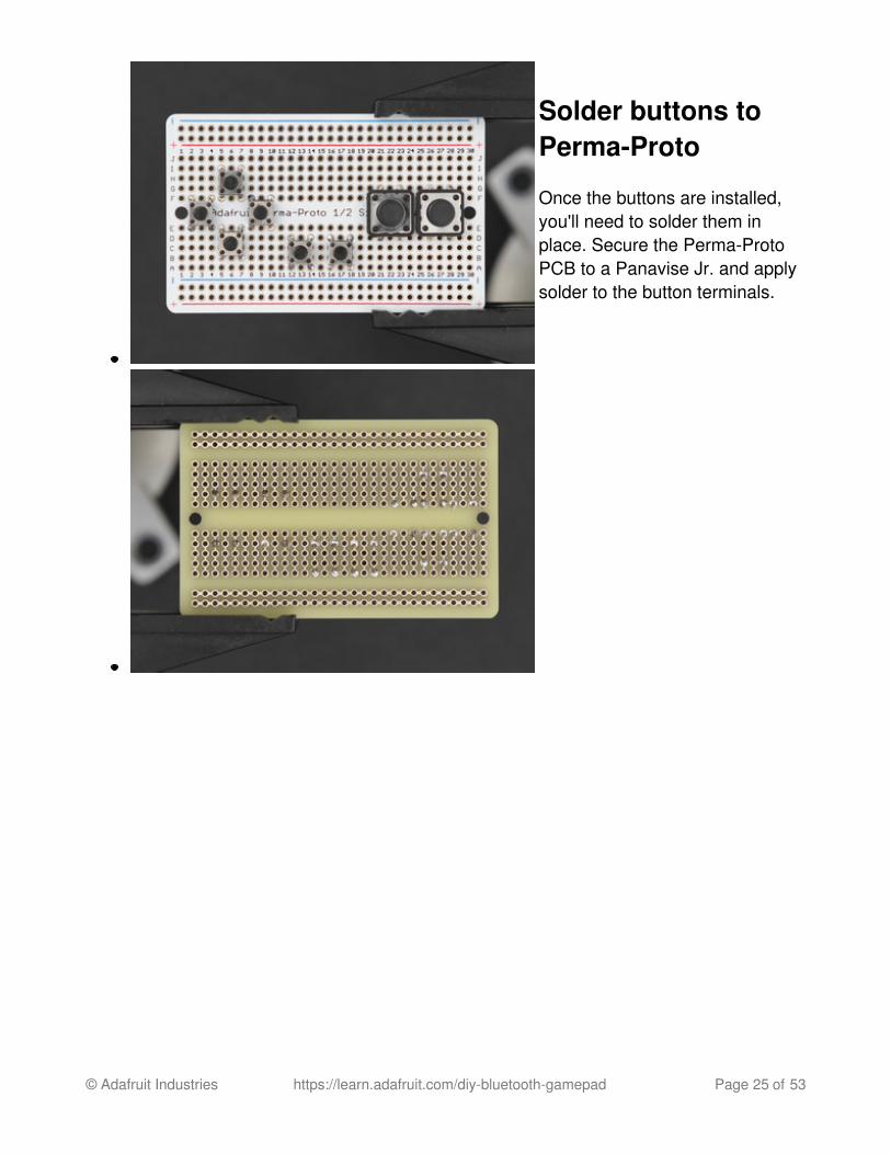
Solder buttons toPerma-Proto
Once the buttons are installed,you'll need to solder them inplace. Secure the Perma-ProtoPCB to a Panavise Jr. and applysolder to the button terminals.
© Adafruit Industries https://learn.adafruit.com/diy-bluetooth-gamepad Page 25 of 53

Saw bottom corners from Perma-Proto PCB
Next up, we'll need to remove the bottom left and right corners from the Perma-Proto PCB.I recommend using a rotary power tool like a DREMEL. You're going to need to do this in awell ventilated area. You're also going to need to wear safety glasses. I recommend usinga 'thin cut' attachment.
© Adafruit Industries https://learn.adafruit.com/diy-bluetooth-gamepad Page 26 of 53

Trimmed Perma-Proto PCB
You're going to want to trim off the power+ground rails from pins 1-2 and 29-30. We won'tbe using these in this project, so it's OK to remove them.
Don't skip this step, its actually very important - The removal of the two corners isnecessary for the PCB to fit into the enclosure.
© Adafruit Industries https://learn.adafruit.com/diy-bluetooth-gamepad Page 27 of 53

Wiring Buttons Ground
Prep Ground Wires
Next up, we need create shortwires that will connect all thebuttons ground together in series.We'll need 8 pieces of 30AWGsilicone-coated stranded wirethat are about 5-10mm long. Stripboth ends of each wire using wirestrippers. Use the helping third
© Adafruit Industries https://learn.adafruit.com/diy-bluetooth-gamepad Page 28 of 53

hands to secure wires whiletinning.
© Adafruit Industries https://learn.adafruit.com/diy-bluetooth-gamepad Page 29 of 53

Ground Wires
Here's the full set of 30AWG silicone-coated wires all cut and tinned. They're short and thin!
© Adafruit Industries https://learn.adafruit.com/diy-bluetooth-gamepad Page 30 of 53

Button Ground Placement
Insert each ground wire into the through-holes before soldering into place. You'll want toassess the placement and double check the front and back of the PCB. In this project, I'musing the right side of the buttons terminals as the ground - so all of them need to be thisway. Note, once the PCB is flipped over, the 'right-side' becomes the 'left-side'. Take this inconsideration, as it can start getting confusing. I myself had to resolder a few times!
© Adafruit Industries https://learn.adafruit.com/diy-bluetooth-gamepad Page 31 of 53

Solder GroundWires
Apply solder to the designatedbutton input through-holes.Ensure the wire is soldered tothe correct through-hole on thepower/ground rail. Use tweezersto assist you while heating upsolder and inserting wires. You'llneed to connect the top andbottom ground rails together bywiring up a piece of wire.
When you've completedsoldering ground wires, snip offany excess terminals/wires withflush diagonal cutters.
© Adafruit Industries https://learn.adafruit.com/diy-bluetooth-gamepad Page 32 of 53
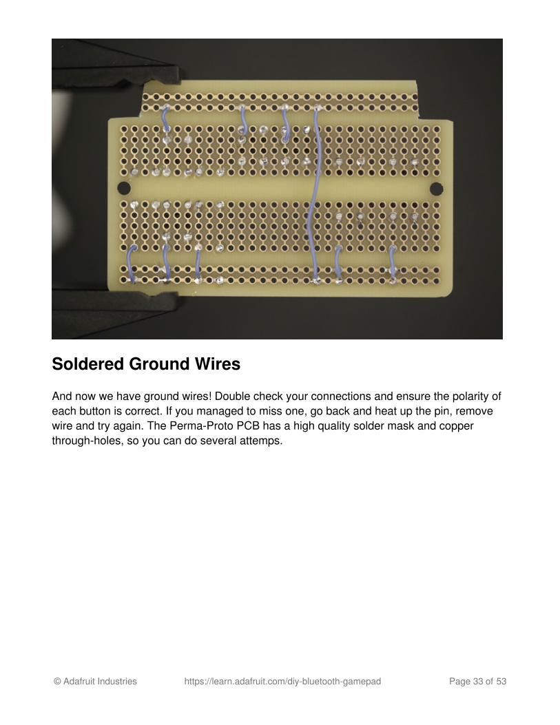
Soldered Ground Wires
And now we have ground wires! Double check your connections and ensure the polarity ofeach button is correct. If you managed to miss one, go back and heat up the pin, removewire and try again. The Perma-Proto PCB has a high quality solder mask and copperthrough-holes, so you can do several attemps.
© Adafruit Industries https://learn.adafruit.com/diy-bluetooth-gamepad Page 33 of 53
Wiring Buttons Input
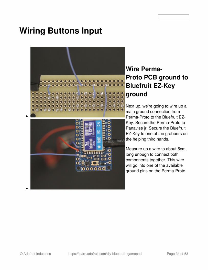
Wire Perma-Proto PCB ground toBluefruit EZ-Keyground
Next up, we're going to wire up amain ground connection fromPerma-Proto to the Bluefruit EZ-Key. Secure the Perma-Proto toPanavise jr. Secure the BluefruitEZ-Key to one of the grabbers onthe helping third hands.
Measure up a wire to about 5cm,long enough to connect bothcomponents together. This wirewill go into one of the availableground pins on the Perma-Proto.
© Adafruit Industries https://learn.adafruit.com/diy-bluetooth-gamepad Page 34 of 53

Wire Buttons to EZ-Key Inputs
Now we need to wire each buttonfrom the Perma-Proto to the inputpins on the Bluefruit EZ-Key.
Measure and cut wires for thebutton inputs. These wires canbe 5cm long. You'll need to dothe same song and dance - stripboth ends, apply solder to tin thetips. Apply solder to the pin andthen insert the wire while solderis molten. You'll need to do thisfor all 8 buttons. Double checkeach pin and wire connectionbefore soldering. You should beconstaintly checking the backand front of the PCB, makingsure you're soldering the correctpin.
© Adafruit Industries https://learn.adafruit.com/diy-bluetooth-gamepad Page 35 of 53

Wired Buttons to Bluefruit EZ-Key
And now we have the button inputs wired to the Bluefruit EZ-Key, yay! You'll want to, yetagain, double check your connections to ensure everything is right.
© Adafruit Industries https://learn.adafruit.com/diy-bluetooth-gamepad Page 36 of 53

Wire BlueTooth Pairbutton to EZ-Key
We'll need an extra 6mm tactilebutton to serve as the bluetoothpair button. This will help you pairthe Bluefruit EZ-Key to differentdevices. You'll need to measureand cut two piecess of 30AWGsilicone-coated stranded wire.Apply heat shrink tubing to theexposed terminals to insulate theconnections.
The two wires will need toconnect to the 3V and BT labeledpins on the Bluefruit EZ-Key.
© Adafruit Industries https://learn.adafruit.com/diy-bluetooth-gamepad Page 37 of 53

Soldered Inputs to Bluefruit EZ-Key
And now we have a complete circuit!
© Adafruit Industries https://learn.adafruit.com/diy-bluetooth-gamepad Page 38 of 53

Heat Shrink Input Wires
Let's go ahead and make the wiring from the button inputs a bit more organized. Cut apiece of heat shrink tubing and split it down the middle. Bundle up all of the input wiresand wrap the piece of heat shrink around the wires. Apply a bit of heat to seal the heatshrink tubing.
Now we can mount the components to the enclosure!
© Adafruit Industries https://learn.adafruit.com/diy-bluetooth-gamepad Page 39 of 53

Assembly
Add screws tobottom cover
Let's start by fastening two #4-403/8 flat Phillips machine screwsinto the two holes on the bottomcover part [not the holes in thecorners]. Fasten until you see thescrew thread slightly protrude thetop of the stand-off - so, not allthe way.
© Adafruit Industries https://learn.adafruit.com/diy-bluetooth-gamepad Page 40 of 53

Mount Micro USBLipo Charger tobottom cover
Let's mount the micro USB lipocharger to the bottom cover.Place it over the stand-offs withthe machine screw lined up withthe mounting hole on the lipocharger PCB. Make sure theUSB charging port is facing theoutter edge. Hold the componentfirmly in place while you fastenthe machine screw, all the way.
© Adafruit Industries https://learn.adafruit.com/diy-bluetooth-gamepad Page 41 of 53

Mount Bluefruit EZ-Key to bottom cover
Next up, we'll need to mount theBluefruit EZ-Key to the bottomcover. Let's do the same songand dace we just did for the lipocharger to the Bluefruit EZ-Key.Note, the mounting holes on theBluefruit EZ-Key are just a bitsmaller than the micro lipocharger, so you'll need to loosenthe hole if the #4-40 machinescrew doesn't go in. I used asharp and pointy #4-40 screw totap the hole - it just barelybroke the PCB because themounting hole is small, so doit slowly and carefully.
© Adafruit Industries https://learn.adafruit.com/diy-bluetooth-gamepad Page 42 of 53

Mount Bluefruit EZ-Key to bottom cover
Now we have both components mounted to the bottom cover.
© Adafruit Industries https://learn.adafruit.com/diy-bluetooth-gamepad Page 43 of 53

Mount BluetoothPair button tobottom cover
There's a small platform for thebluetooth pair button to rest on.You may want to bend the leadsapart. Add a dap of super glue tothe top surface of the platformand then quickly place the buttonon top, with the button facing theoutter edge. Allow glue to drybefore proceeding.
© Adafruit Industries https://learn.adafruit.com/diy-bluetooth-gamepad Page 44 of 53

Plug in 500mAh Lithium Polymer Battery
OK, now is a good time to plug in the JST cable from the battery to the JST port on themicro USB lipo charger.
© Adafruit Industries https://learn.adafruit.com/diy-bluetooth-gamepad Page 45 of 53

Mount Perma-Prototo bottom cover
Now we need to mount thePerma-Proto PCB to the bottomcover. Carefully coil the inputwires underneath the PCB andplace it on top of the two tallstand-offs. Line up the mountholes with the stand-offs andhold the PCB in place. Insert two#4-40 3/8 flat Phillips machinescrews into the Perma-Proto untilit's fastened to the stand offs.Fasten all the way until the PCBis completely secured.
© Adafruit Industries https://learn.adafruit.com/diy-bluetooth-gamepad Page 46 of 53

Insert 500mAh battery
We need to insert the lithium polymer in between the Perma-Proto PCB and the bottomcover. There should be enough clearance for the battery. You'll want to arrange the wiresso that they aren't being kinked or scrunched up.
Be careful not to scratch or puncture the battery!
© Adafruit Industries https://learn.adafruit.com/diy-bluetooth-gamepad Page 47 of 53

Install Ninjaflex buttons into case
Before we insert the circuit into the top enclosure, add the ninjaflex rubbery buttons to theenclosure. These need to be in place before the circuit is installed.
© Adafruit Industries https://learn.adafruit.com/diy-bluetooth-gamepad Page 48 of 53

Insert circuit intocase
Place the circuit into theenclosure at a 45-ish degreeangle so that the Perma-ProtoPCB goes underneath the clipson the inside fo the enclosure.Ensure the micro USB port onthe lipo charger is facing the cutout on the encosure. Carefullyslide it into the enclosure, butdon't close it completely, yet!
© Adafruit Industries https://learn.adafruit.com/diy-bluetooth-gamepad Page 49 of 53

Install slide switchinto case
With the circuit half-way inserted,pull out the slide switch from thecircuit and press it down into thecut out for the slide switch. Theclips will hold the switch andprevent it from being pushed allthe way inside the enclosure.
Once the slide switch is insertedin place, close up the bottomcover!
© Adafruit Industries https://learn.adafruit.com/diy-bluetooth-gamepad Page 50 of 53

Fasten bottom cover to case
Insert four #4-40 3/8 flat Phillips machine screws to the corners of the bottom cover. Fastenall the way to tighten and completely close the enclosure.
© Adafruit Industries https://learn.adafruit.com/diy-bluetooth-gamepad Page 51 of 53

Add cover to topcase
To finish off this project, you canadd a cover to the front of theenclosure to change up colorscheme. In this project I used ablack color to add contrast to thepink enclosure. You can applyadhesives like E600 to the partsfor a perminent seal, or you canuse funtac like I did.
© Adafruit Industries https://learn.adafruit.com/diy-bluetooth-gamepad Page 52 of 53

Charge Battery and Play!
And thats about it! The circuit is finished, project assembled and ready to play! Or is it? Irecommend fully charging the 500mAh battery before playing. Plug in a micro USB cable tothe lipo charger. The charger has an on-board LED indicator that lights green when thebattery is fully charged. Red LED indicates the battery is charging.
Changing Button Mapping
Check the EZ-Key introduction guide (http://adafru.it/dpy) for button mapping details!
© Adafruit Industries Last Updated: 2016-09-03 02:23:20 AM UTC Page 53 of 53

Pairing with Devices
A freshly baked, 'never-been-used' Bluefruit EZ-Key will automatically start searching for adevice to pair with. Your bluetooth enabled device should pick up the EZ-Key within aminute. If you're having issues with pairing, or unfamiliar with pairing bluetooth devices, youshould check out the pairing page on the EZ-Key introduction guide (http://adafru.it/dpy).