DIVISIONS OF DYNAMICS KINEMATICS Deals with Motion …
103
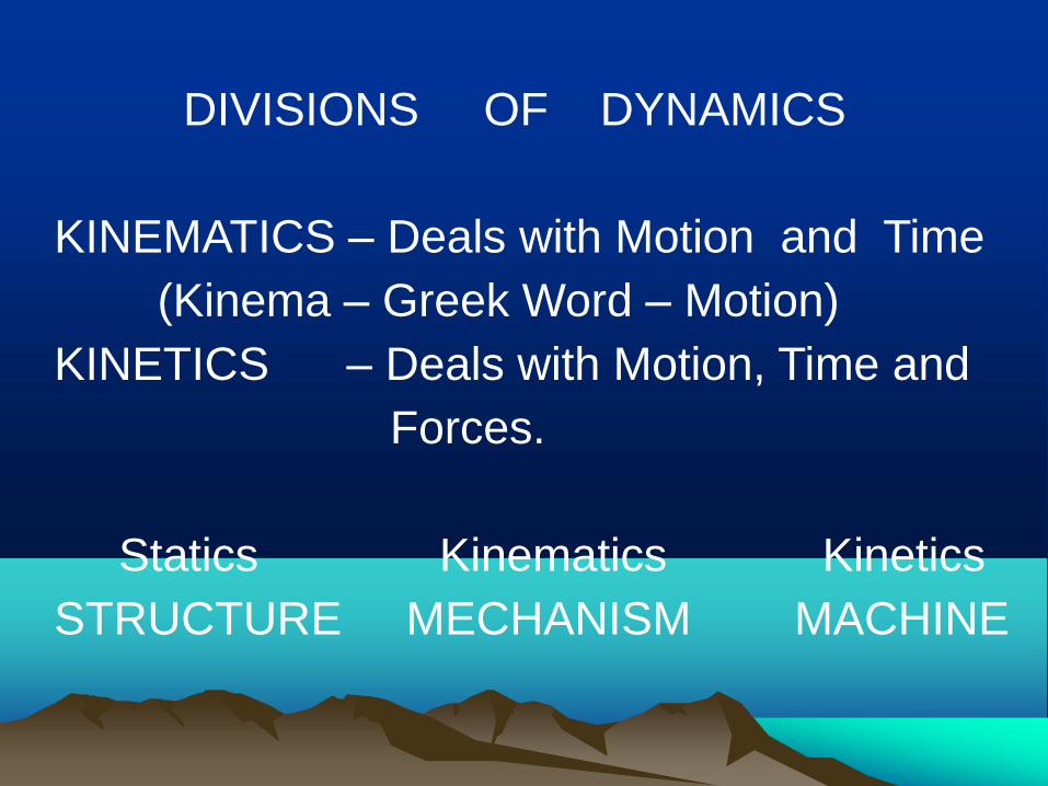
DIVISIONS OF DYNAMICS KINEMATICS – Deals with Motion and Time (Kinema – Greek Word – Motion) KINETICS – Deals with Motion, Time and Forces. Statics Kinematics Kinetics STRUCTURE MECHANISM MACHINE
Transcript of DIVISIONS OF DYNAMICS KINEMATICS Deals with Motion …
DIVISIONS OF DYNAMICS KINEMATICS – Deals with Motion and Time (Kinema – Greek Word – Motion) KINETICS – Deals with Motion, Time and Forces. Statics Kinematics Kinetics STRUCTURE MECHANISM MACHINE

Some Definitions
• Machine – device to transfer or transform energy to do useful work.
• Mechanism – device to transfer or
transform given input motion to specified output motion
• Structure – a single body with no motion /
combination of bodies with no relative motion
Classification of Mechanisms
• Based on the nature of output speed
• Uniform motion mechanism
• Non-uniform motion mechanism
Shortcut to flat belt.lnk

Uniform Motion Mechanisms
Uniform Motion – Equal Displacement For Equal Time Interval Examples : All Gear Drives All Chain Drives Belt Drives without slip


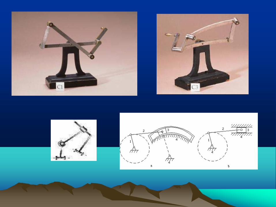
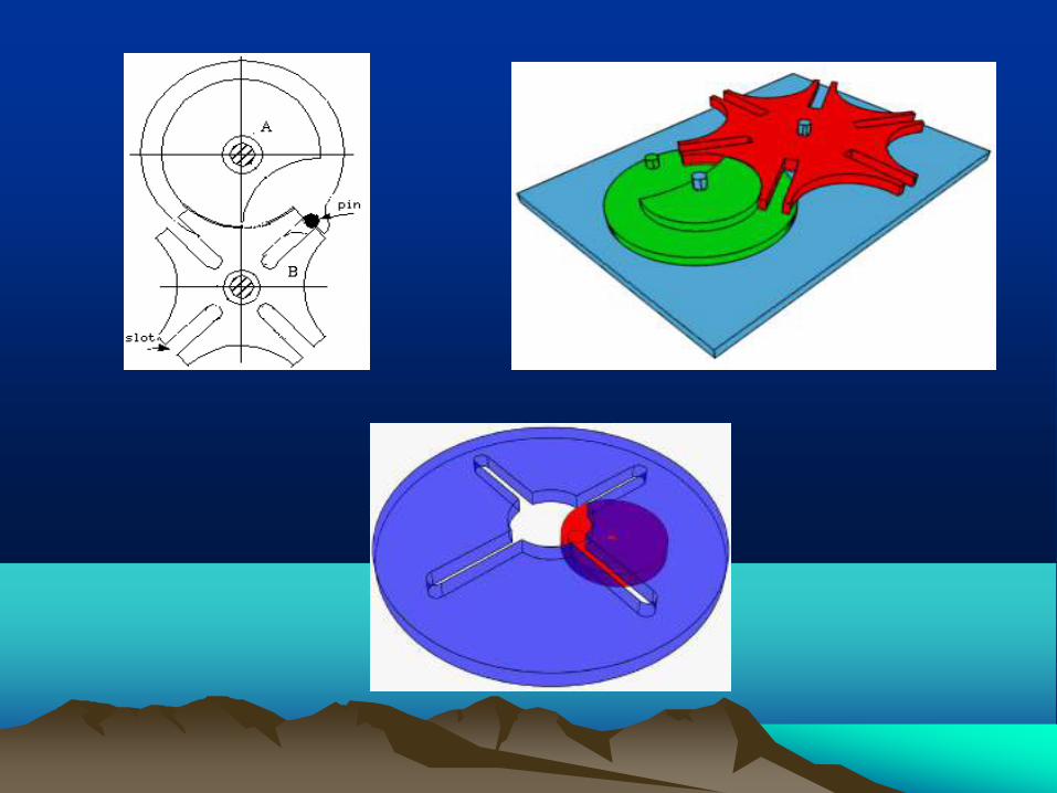
Non-Uniform Motion Mechanisms
Non-Uniform Motion – Unequal Displacement For Equal Time Interval Examples : Linkage Mechanisms Cam Mechanisms Geneva Wheel
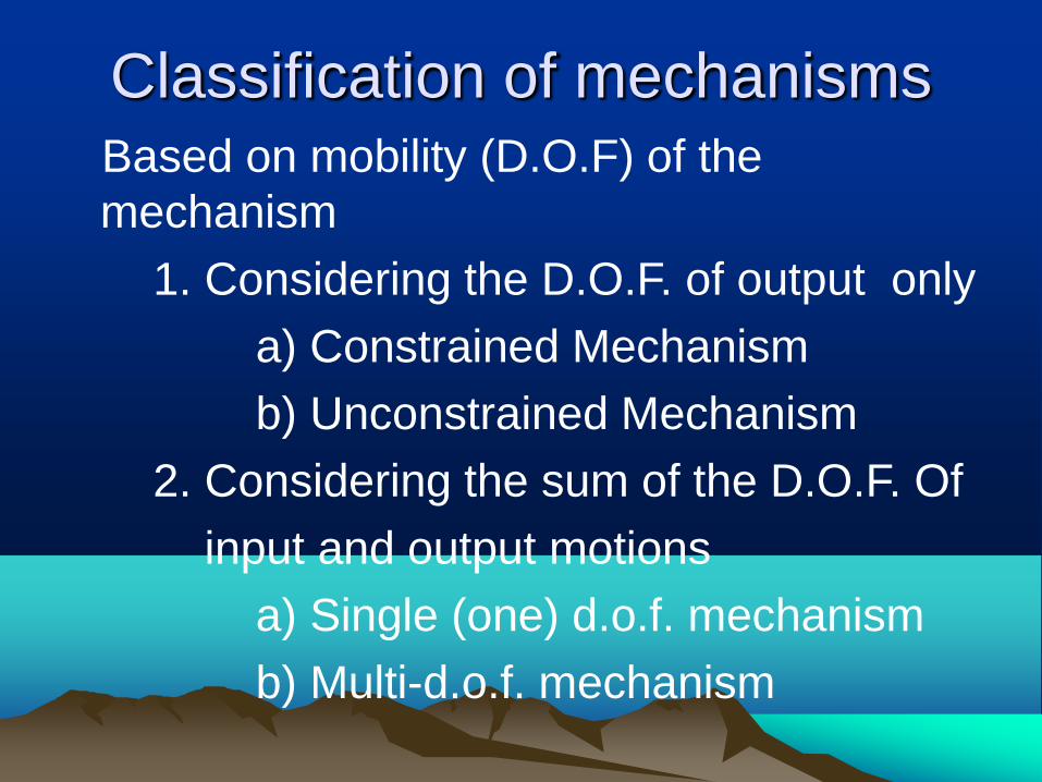
Classification of mechanisms Based on mobility (D.O.F) of the
mechanism
1. Considering the D.O.F. of output only
a) Constrained Mechanism b) Unconstrained Mechanism
2. Considering the sum of the D.O.F. Of
input and output motions a) Single (one) d.o.f. mechanism
b) Multi-d.o.f. mechanism

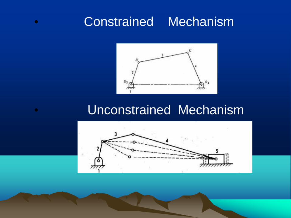
Constrained Mechanism
• One independent output motion. Output member is constrained to move in a particular manner only.
• Example: Four-bar mechanism Slider Crank Mechanism Five-bar mechanism with two inputs
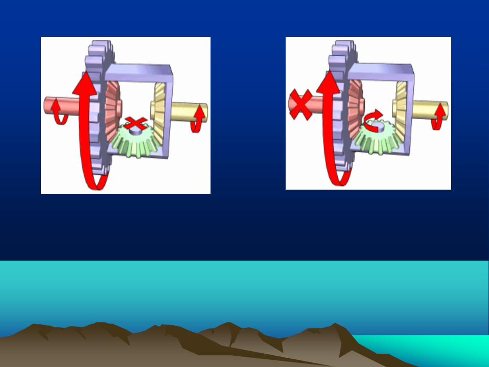
Unconstrained mechanism
• Output motion has more than one D.O.F. • Example: Automobile Differential during turning the vehicle on a curve Five-bar mechanism with one input

Single D.O.F Mechanism
Sum of the input and output D.O.F. is two. Single D.O.F. Motion - One Independent Input motion and one independent output motion Examples : Four-Bar Mechanism Cam-Follower Mechanism


Multi D.O.F. Mechanism Sum of the input and output motion D.O.F. is more than two. Multi D.O.F. Motion – More than one Independent Output / Input Motions Examples : Automobile Differential 3-D Cam Mechanism (Camoid) Five-Bar Mechanism

Classification of mechanisms
• Based on the connection of the output member
• Open mechanism
• Closed mechanism
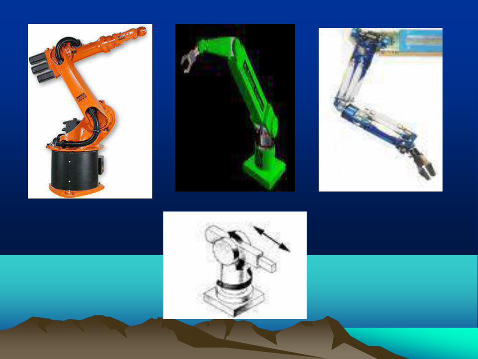
Open Mechanism
• Output member not connected to the fixed link / frame
• Robot arms
• Arms of earth movers

Closed Mechanism
• Output member connected to the frame.
• Four-bar mechanism
• Slider-crank mechanism
• Cam follower mechanism
Components of Mechanisms
• Link / element
• Kinematic pairs / joints
• Kinematic chain

Link / Element A single resistant body / combination of resistant bodies having relative motion with another resistant body / combination of resistant bodies.
Rigid Body Flexible Body Liquid
A

• Link with one Node : Unary Link • Link with two Nodes : Binary Link (a) • Link with three Nodes : Ternary Link (b) • Link with four Nodes : Quaternary Link (c)

Kinematic Pairs / Joints
• Combination of two links kept in permanent contact permitting particular kind(s) of relative motion(s) between them

Classification of Pairs
• BASED ON NATURE OF CONTACT BETWEEN LINKS: 1. Lower Pairs -- Surface Contact 2. Higher Pairs – Point or Line Contact
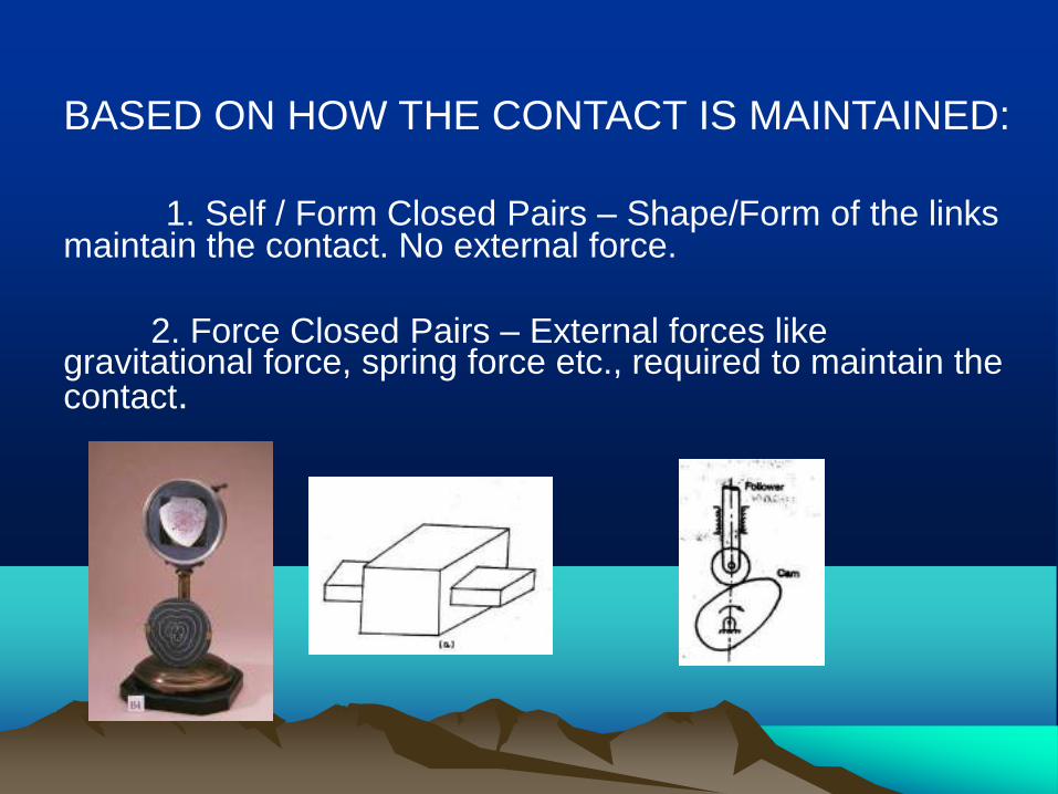
BASED ON HOW THE CONTACT IS MAINTAINED: 1. Self / Form Closed Pairs – Shape/Form of the links maintain the contact. No external force. 2. Force Closed Pairs – External forces like gravitational force, spring force etc., required to maintain the contact.

• BASED ON THE DEGREE OF FREEDOM 1. Type I / Class I – One D.O.F 2. Type II / Class II – Two D.O.F 3. Type III / Class III – Three D.O.F 4. Type IV / Class IV – Four D.O.F 5. Type V / Class V – Five D.O.F BASED ON THE NATURE OF CONSTRAINT 1. (Completely) Constrained Pair - 1 D.O.F 2. Unconstrained Pair – More than 1 D.O.F 3. Successfully Constrained pair – Unconstrained pair converted as Constrained pair by some means.

• Completely Constrained Pair • Successfully Unconstrained Pair Constrained Pair

• BASED ON THE POSSIBLE MOTIONS (Few Important Types only)
Name of Pair Letter Symbol D.O.F 1. Revolute / Turning Pair R 1 2. Prismatic / Sliding Pair P 1 3. Helical / Screw Pair H 1 4. Cylindrical Pair C 2 5. Spherical / Globular Pair S (or) G 3 6. Flat / Planar Pair E 3 7. Cylindric Plane Pair Cp 4 8. Spheric Plane Pair Sp 5


Kinematic Chain
• Assembly of links and pairs to produce required / specified output motion(s) for given input motion(s)

Mechanism
• A kinematic chain with one link fixed /
stationary

Mobility / D.O.F of Mechanism • No. of inputs required to get a constrained
mechanism (or) no. of position variables needed to sketch the mechanism with all link lengths known.
• KUTZBACH CRITERION FOR PLANAR
MECHANISM • F = 3(n-1)-2P1-1P2
• F – D.O.F n – No. of links • P1 – No. of kinematic pairs with 1 D.O.F. • P2 – No. of kinematic pairs with 2 D.O.F.
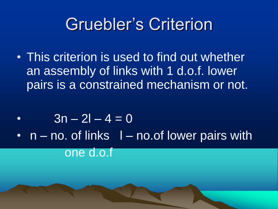
Gruebler’s Criterion
• This criterion is used to find out whether an assembly of links with 1 d.o.f. lower pairs is a constrained mechanism or not.
• 3n – 2l – 4 = 0 • n – no. of links l – no.of lower pairs with one d.o.f

F < 0 Pre-loaded structure Super structure F = 0 Structure F = 1 Constrained Mechanism F > 1 Unconstrained Mechanism
• Constrained Mechanism • Unconstrained Mechanism
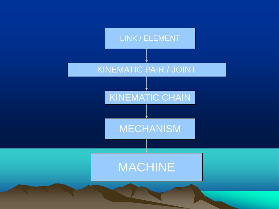
LINK / ELEMENT
KINEMATIC PAIR / JOINT
KINEMATIC CHAIN
MECHANISM
MACHINE
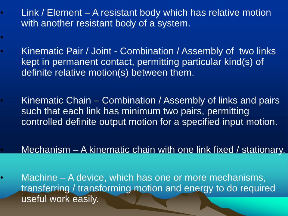
• Link / Element – A resistant body which has relative motion
with another resistant body of a system.
•
• Kinematic Pair / Joint - Combination / Assembly of two links kept in permanent contact, permitting particular kind(s) of definite relative motion(s) between them.
• Kinematic Chain – Combination / Assembly of links and pairs such that each link has minimum two pairs, permitting controlled definite output motion for a specified input motion.
• Mechanism – A kinematic chain with one link fixed / stationary.
• Machine – A device, which has one or more mechanisms, transferring / transforming motion and energy to do required useful work easily.

MOBILITY OR DEGREE OF FREEDOM
• For a Link – Six in spatial motion, three in planar motion.
• For a Kinematic Pair – Number of independent co-
ordinates/pair variables to specify the position of one link with another link (OR) number of independent relative motions possible between the links. Maximum five and minimum one in spatial motion. Maximum two and minimum one in planar motion.
• For a Kinematic Chain/Mechanism – Number of
independent position variables to sketch the configuration with known link lengths (OR) number of input motions required to get a constrained output motion
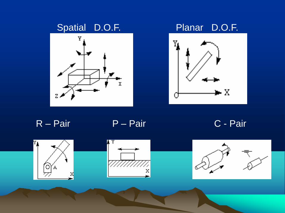
Spatial D.O.F. Planar D.O.F.
R – Pair P – Pair C - Pair

Kinematic Inversions
• Process of obtaining different mechanisms from the same kinematic chain, by fixing different links in turn, is known as
kinematic inversion.
Four inversions are possible from four-bar
kinematic chain.

Formation of four-bar mechanism
• No. of links – 4, No. of pairs – 4.
• All the pairs are revolute pairs.
• Links are :1. Fixed link or Frame • 2. Input Link
• 3. Coupler
• 4. Output link or Follower

Assembly Condition
• Lengths of links: Longest link - l
Shortest link - s
Intermediate links – p, q
l < s + p + q
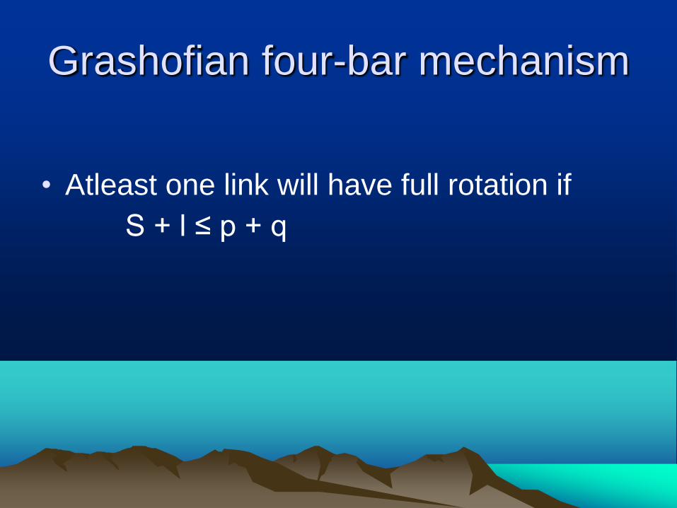
Grashofian four-bar mechanism
• Atleast one link will have full rotation if S + l ≤ p + q

GRASHOF’ S LAW
In a planar four bar revolute pair kinematic chain if the sum of the lengths of the shortest and the longest links is less than or equal to the sum of the lengths of the other two intermediate links at least one link will have full rotation.
Mechanisms obtained from the kinematic chain satisfying these conditions are known as Grashofian Mechanisms.
Mechanisms obtained from the kinematic chain which are not obeying these conditions are known as Non-Grashofian Mechanisms.

Inversions of four bar Mechanisms are named based on the motions of input link and output link. Crank - Link with 360 degree rotation Rocker/Lever – Link with less than 360 degree rotation

Four- bar Inversions
• Crank – Rocker Mechanisms (Two)
• Drag Link / Double Crank Mechanism
• Double – Rocker Mechanism • Above are Grashofian Inversions
• All four non-Grashofian inversions are Double – Rocker mechanisms
Rockers of Grashofian Mechanisms will have less than 180 degree rotation. Rockers of Non-Grashofian Mechanisms can have greater than 180 degree rotation.

KINEMATIC CHAIN
MECHANISM
One Link Fixed
Inversion of the kinematic chain depends upon which link is fixed.


Conditions for Inversions
• POSITION OF F0UR – BAR INVERSION
SHORTEST LINK
• Adjacent to the fixed link Crank – Rocker
• Fixed link itself Drag Link (Double Crank)
• Opposite to fixed link Double Rocker

Examples for Crank – Rocker Mechanism 1. Wind shield wiper mechanism on Driver Side 2. Sewing Machine Treadle Mechanism

3. Grinding Wheel Treadle Mechanism 4. Pedaling action of a Bicycle
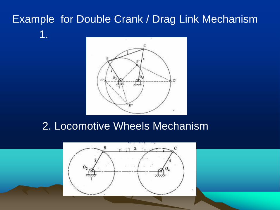
Example for Double Crank / Drag Link Mechanism 1. 2. Locomotive Wheels Mechanism

Example for Double Rocker Mechanism 1. Wind Shield wiper on Passenger Side 2. Ackerman's Steering Gear Mechanism


1
Cams
• Cams are used to convert rotary motion to oscillatory motion (almost always) or oscillatory motion to rotary motion (rarely)
• For high speed applications – example, internal combustion engines
• Objectives of this chapter: – Learn fundamental concepts and terminology
– Learn how to design a cam and follower set to achieve a desired output motion.

2
Cam types
Plate cam
Wedge cam
Barrel cam
Face cam
y
y
y
y

3
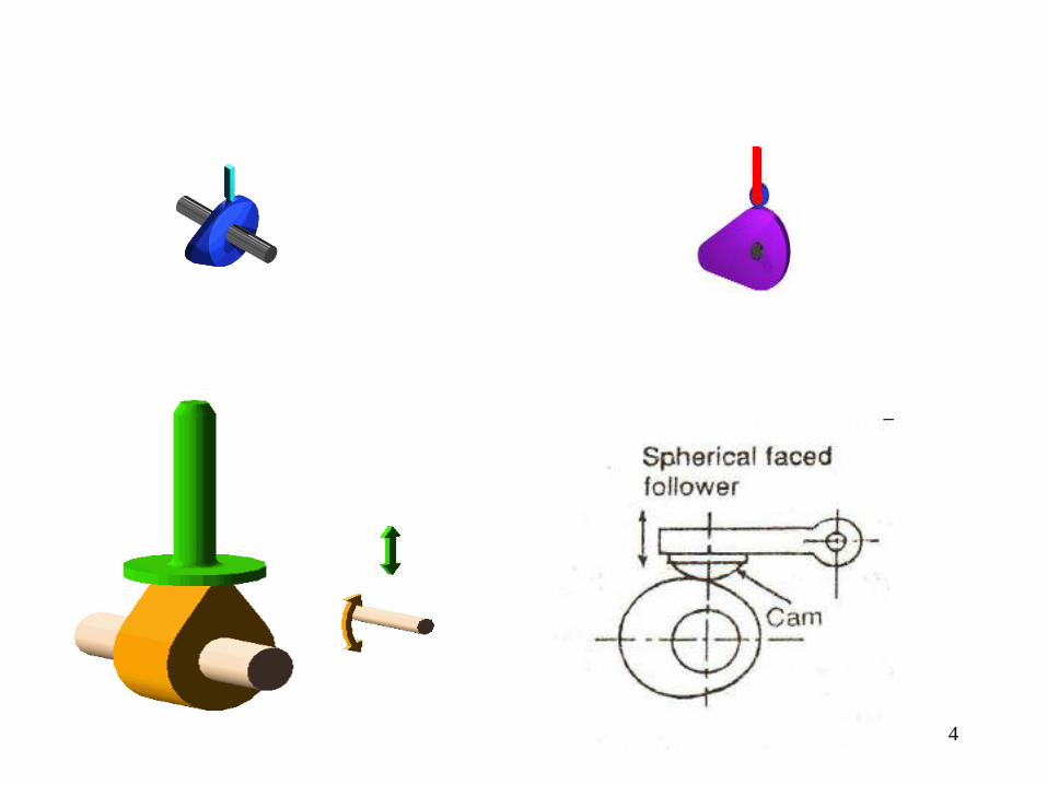
1.3 Classification of followers
1.3.1 According to the shape of follower
• Knife edge follower
• Roller follower
• Flat faced follower
• Spherical faced follower
4
5
1.3.2 According to the path of motion of follower
a) Radial follower
b) Offset follower
6
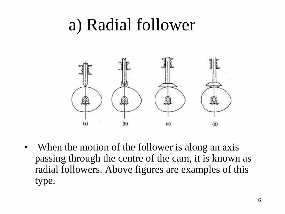
a) Radial follower
• When the motion of the follower is along an axis passing through the centre of the cam, it is known as radial followers. Above figures are examples of this type.

7
b) Offset follower
When the motion of the follower is along an axis away from the axis of the cam centre, it is called off-set follower. Above figures are examples of this type.

8
Displacement diagrams • Cam-follower: usually 1-DOF system
rise dwell return dwell
y

9
Displacement diagram types
• Uniform motion, – Constant velocity – Problem: infinity acceleration at point where
dwell portion starts
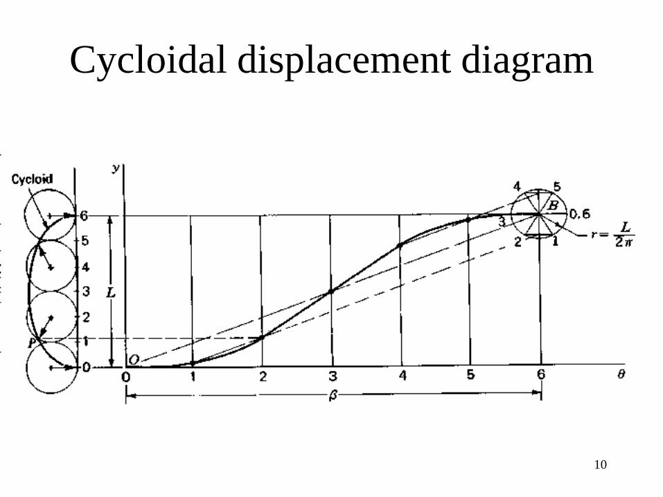
• Parabolic-uniform – Can be shown that acceleration is constant
• Sinusoidal (simple harmonic motion) • Cycloidal
10
Cycloidal displacement diagram
11
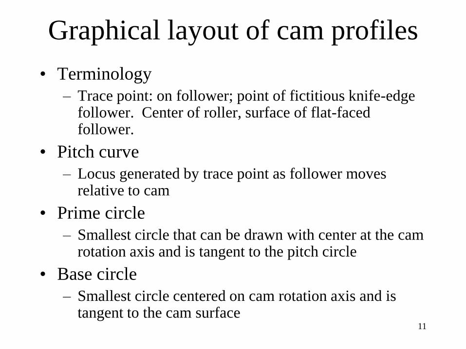
Graphical layout of cam profiles
• Terminology – Trace point: on follower; point of fictitious knife-edge
follower. Center of roller, surface of flat-faced follower.
• Pitch curve – Locus generated by trace point as follower moves
relative to cam
• Prime circle – Smallest circle that can be drawn with center at the cam
rotation axis and is tangent to the pitch circle
• Base circle – Smallest circle centered on cam rotation axis and is
tangent to the cam surface

12
Layout of cam profile: roller follower
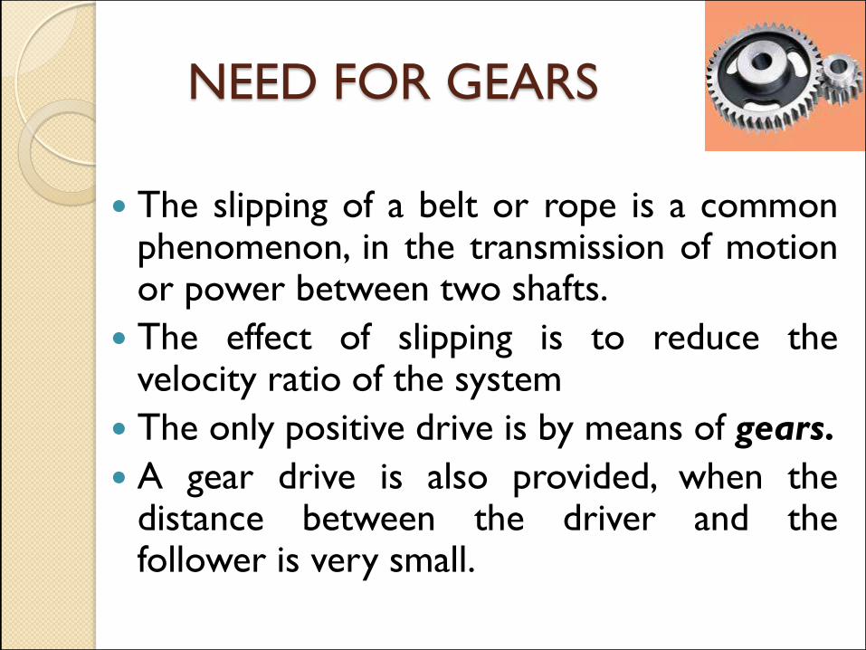
NEED FOR GEARS
The slipping of a belt or rope is a common phenomenon, in the transmission of motion or power between two shafts.
The effect of slipping is to reduce the velocity ratio of the system
The only positive drive is by means of gears.
A gear drive is also provided, when the distance between the driver and the follower is very small.

FRICTION WHEELS

Advantages of Gear Drive
It transmits exact velocity ratio.
It may be used to transmit large
power.
It has high efficiency.
It has reliable service.
It has compact layout.

Disadvantages of Gear Drive
The manufacture of gears require
special tools and equipment.
The error in cutting teeth may
cause vibrations and noise during
operation.

Classification of Gears According to the position of axes of
the shafts.
(a) Parallel, (b) Intersecting, and
(c) Non-intersecting and non-parallel.
According to the peripheral velocity
of the gears.
(a) Low velocity, (b) Medium velocity, and (c) High velocity.
According to the type of gearing. (a) External gearing, (b) Internal gearing, and (c) Rack and
pinion.

According to the position of axes
of the shafts
Spur gears Parallel helical gears Herringbone gears
(or double-helical gears)
Gears for connecting parallel shafts
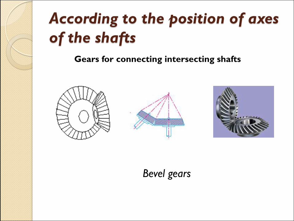
According to the position of axes
of the shafts
Gears for connecting intersecting shafts
Bevel gears

According to the position of axes
of the shafts
Neither parallel nor intersecting shafts
Crossed-helical gears
According to the peripheral velocity
of the gears
The gears having velocity less than 3 m/s
are termed as low velocity gears.
Gears having velocity between 3 and 15
m/s are known as medium velocity
gears.
If the velocity of gears is more than 15 m/s,
then these are called high speed gears.
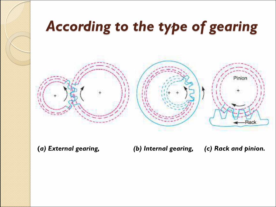
According to the type of gearing
(a) External gearing, (b) Internal gearing, (c) Rack and pinion.

Terms Used in Gears
Pitch circle: It is an imaginary circle which by pure rolling action, would give the same motion as the actual gear.

Terms Used in Gears
Pitch circle diameter: It is the diameter of the pitch circle. The size of the gear is usually specified by the pitch circle diameter. It is also known as pitch diameter.
Terms Used in Gears
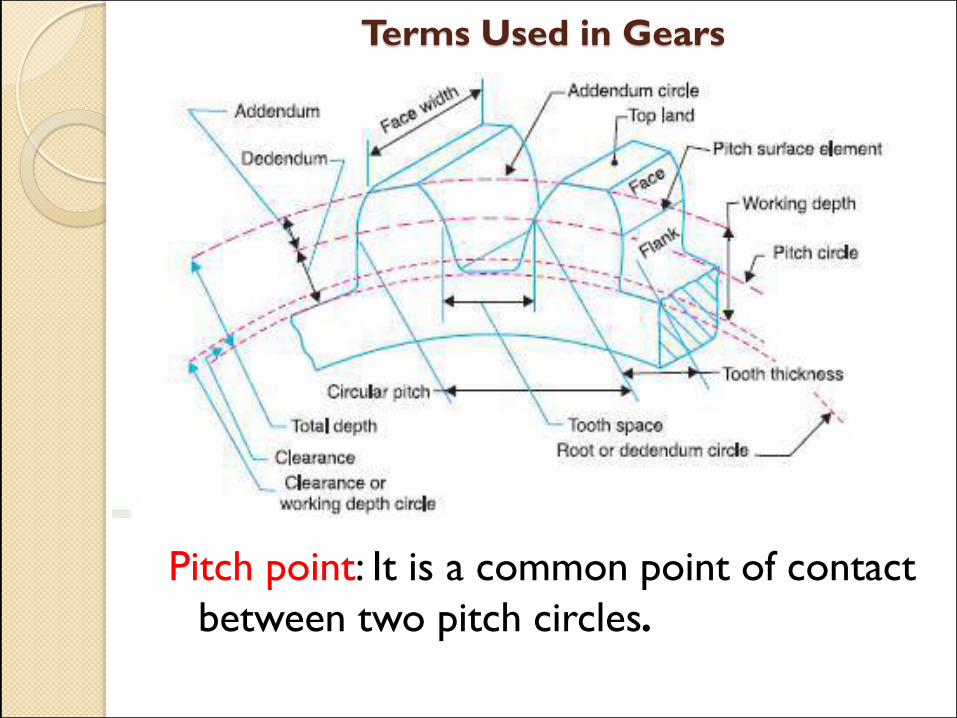
Pitch point: It is a common point of contact
between two pitch circles.

Terms Used in Gears
Pitch surface: It is the surface of the rolling discs which the meshing gears have replaced at the pitch circle.

Terms Used in Gears
Pressure angle or angle of obliquity: It is the angle between
the common normal to two gear teeth at the point of contact
and the common tangent at the pitch point. It is usually
denoted by φ. The standard pressure angles are14.5° and 20°.
It can also be defined as The angle between a tooth profile
and a radial line at the pitch circle.

Terms Used in Gears
Addendum: It is the radial distance of a tooth
from the pitch circle to the top of the tooth.
Terms Used in Gears
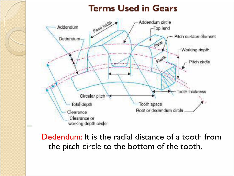
Dedendum: It is the radial distance of a tooth from the pitch circle to the bottom of the tooth.

Terms Used in Gears
Addendum circle : It is the circle drawn through the top of the teeth and is concentric with the pitch circle.

Terms Used in Gears
Dedendum circle: It is the circle drawn through the bottom of the teeth. It is also called root circle.
Root circle diameter = Pitch circle diameter × cos φ,
where φ is the pressure angle.
Terms Used in Gears
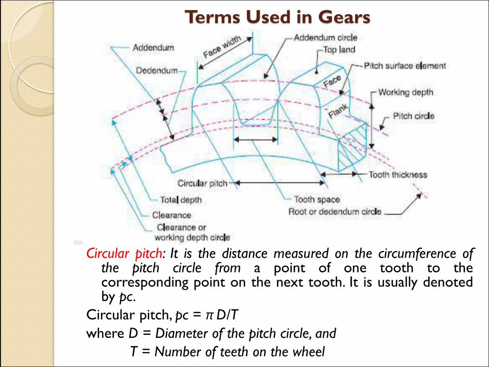
Circular pitch: It is the distance measured on the circumference of the pitch circle from a point of one tooth to the corresponding point on the next tooth. It is usually denoted by pc.
Circular pitch, pc = π D/T
where D = Diameter of the pitch circle, and
T = Number of teeth on the wheel

Terms Used in Gears
Diametral pitch: It is the ratio of number of teeth to the pitch circle diameter in millimetres.

Terms Used in Gears
Module: It is the ratio of the pitch circle diameter in millimeters to the number of teeth. It is usually denoted by m.
Mathematically,
Module, m = D /T

Terms Used in Gears
Clearance: It is the radial distance from the top of the tooth to the bottom of the tooth, in a meshing gear. A circle passing through the top of the meshing gear is known as clearance circle.

Terms Used in Gears
Total depth: It is the radial distance between the addendum and the dedendum circles of a gear. It is equal to the sum of the addendum and dedendum.
Terms Used in Gears
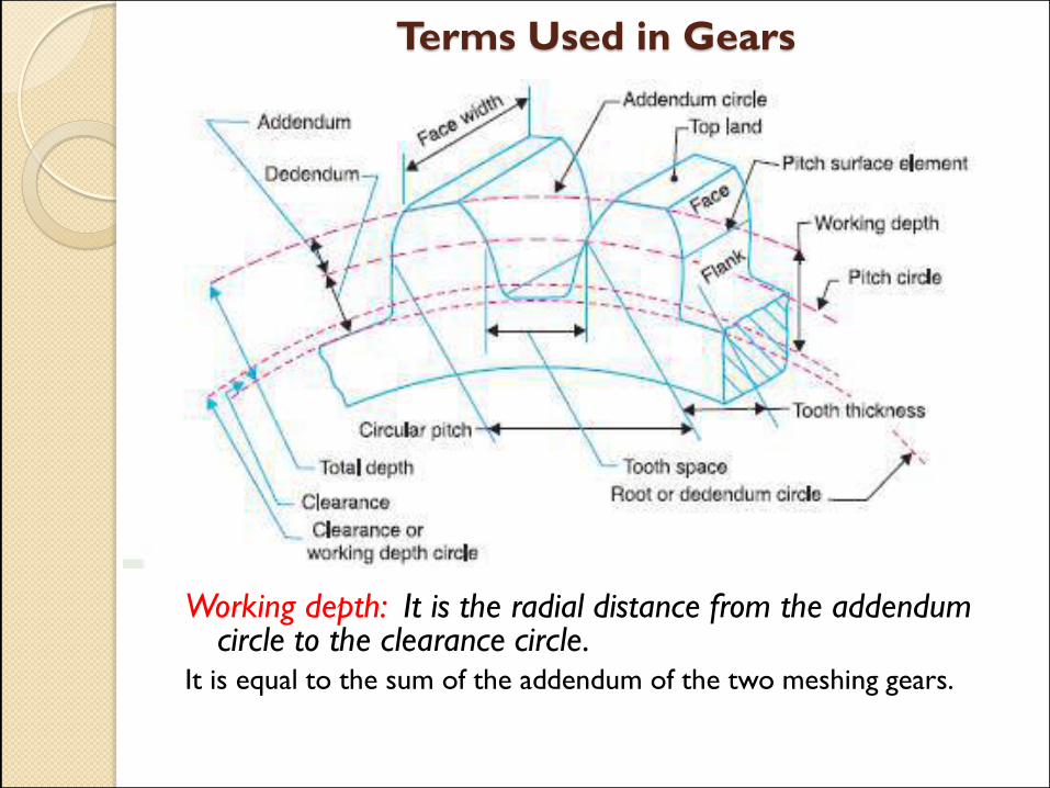
Working depth: It is the radial distance from the addendum circle to the clearance circle.
It is equal to the sum of the addendum of the two meshing gears.
Terms Used in Gears
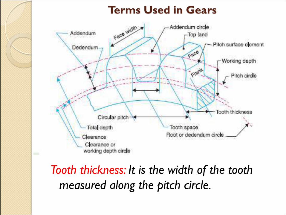
Tooth thickness: It is the width of the tooth
measured along the pitch circle.

Terms Used in Gears
Tooth space : It is the width of space between the two adjacent teeth measured along the pitch circle.

Terms Used in Gears
Backlash: It is the difference between the tooth space and the tooth thickness, as measured along the pitch circle. Theoretically, the backlash should be zero, but in actual practice some backlash must be allowed to prevent jamming of the teeth due to tooth errors and thermal expansion.
Terms Used in Gears
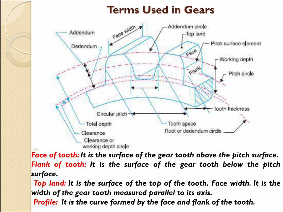
Face of tooth: It is the surface of the gear tooth above the pitch surface.
Flank of tooth: It is the surface of the gear tooth below the pitch
surface.
Top land: It is the surface of the top of the tooth. Face width. It is the
width of the gear tooth measured parallel to its axis.
Profile: It is the curve formed by the face and flank of the tooth.

Terms Used in Gears
Path of contact: It is the path traced by the point of contact of two teeth from the beginning to the end of engagement.

Terms Used in Gears
Length of the path of contact : It is the length of the common normal cut-off by the addendum circles of the wheel and pinion.

Terms Used in Gears
Arc of contact: It is the path traced by a point on the pitch circle from the beginning to the end of engagement of a given pair of teeth. The arc of contact consists of two parts, i.e.
Arc of approach: It is the portion of the path of contact from the beginning of the engagement to the pitch point.
Arc of recess: It is the portion of the path of contact from the pitch point to the end of the engagement of a pair of teeth