DIVISION 500 - STRUCTURES - Maine · DIVISION 500 - STRUCTURES SECTION 501 - FOUNDATION PILES...
149
DIVISION 500 - STRUCTURES SECTION 501 - FOUNDATION PILES 501.01 Description This work shall consist of furnishing and driving piles and casings, of the types and dimensions specified on the contract plans, to the required ultimate capacity. Piles shall conform to and be installed, as detailed in these specifications, in reasonably close conformity to the lines, grades, and locations shown on the plans or as authorized by the Resident. Work under this item shall also consist of any pile testing specified by the project contract plans and described in these specifications. 501.02 Materials Materials shall meet the requirements of the following sections of Division 700 - Materials: Steel Pipe Piles 711.01 H-Beam Pile Tips 711.10 Structural Steel 713.01 H-beam piles shall be structural steel and shall meet the requirements of AASHTO M183/ 183M (ASTM A36/A36M). Mill test reports will be required. Notch toughness tests will not be required. Concrete for Steel Pipe Piles and Steel Casings shall be Class S and shall meet the requirements of Section 502 - Structural Concrete. Steel casings shall conform to the material requirements of Section 711.01 - Steel Pipe Piles. Reinforcing steel for Steel Pipe Piles and Steel Casings when called for, shall meet the requirements of Section 503 - Reinforcing Steel. 501.021 Ordering Piles The Contractor shall order all pilings from an itemized list of order lengths provided by the Resident. When extensions of piles are necessary, the extension lengths will be ordered by the Contractor from a written list provided by the Resident. 501.03 Equipment for Driving Piles Hammers Piles shall be driven with approved power-actuated impact hammers powered with steam/air, diesel fuel or hydraulics (hereinafter referred to as power hammers). Gravity drop hammers (hereinafter referred to as drop hammers), except as noted on the plans, shall only be used to drive timber piles. When drop hammers are used to drive timber piles, the ram shall be between 900 and 1600 kg [2,000 and 3,500 lb] and the height of drop shall not exceed 5 m [15 ft]. In no case shall the ram weight be less than the combined weight of the drive head and pile. All drop hammers shall be equipped with hammer guides to insure concentric impact on the drive head. 5-1
-
Upload
phungthien -
Category
Documents
-
view
213 -
download
0
Transcript of DIVISION 500 - STRUCTURES - Maine · DIVISION 500 - STRUCTURES SECTION 501 - FOUNDATION PILES...

DIVISION 500 - STRUCTURES
SECTION 501 - FOUNDATION PILES 501.01 Description This work shall consist of furnishing and driving piles and casings, of the types and dimensions specified on the contract plans, to the required ultimate capacity. Piles shall conform to and be installed, as detailed in these specifications, in reasonably close conformity to the lines, grades, and locations shown on the plans or as authorized by the Resident. Work under this item shall also consist of any pile testing specified by the project contract plans and described in these specifications. 501.02 Materials Materials shall meet the requirements of the following sections of Division 700 - Materials:
Steel Pipe Piles 711.01 H-Beam Pile Tips 711.10 Structural Steel 713.01 H-beam piles shall be structural steel and shall meet the requirements of AASHTO M183/ 183M (ASTM A36/A36M). Mill test reports will be required. Notch toughness tests will not be required. Concrete for Steel Pipe Piles and Steel Casings shall be Class S and shall meet the requirements of Section 502 - Structural Concrete. Steel casings shall conform to the material requirements of Section 711.01 - Steel Pipe Piles. Reinforcing steel for Steel Pipe Piles and Steel Casings when called for, shall meet the requirements of Section 503 - Reinforcing Steel. 501.021 Ordering Piles The Contractor shall order all pilings from an itemized list of order lengths provided by the Resident. When extensions of piles are necessary, the extension lengths will be ordered by the Contractor from a written list provided by the Resident. 501.03 Equipment for Driving Piles
Hammers Piles shall be driven with approved power-actuated impact hammers powered with steam/air, diesel fuel or hydraulics (hereinafter referred to as power hammers). Gravity drop hammers (hereinafter referred to as drop hammers), except as noted on the plans, shall only be used to drive timber piles. When drop hammers are used to drive timber piles, the ram shall be between 900 and 1600 kg [2,000 and 3,500 lb] and the height of drop shall not exceed 5 m [15 ft]. In no case shall the ram weight be less than the combined weight of the drive head and pile. All drop hammers shall be equipped with hammer guides to insure concentric impact on the drive head.
5-1

With the written approval of the Resident, installation of non-displacement piles may be initiated with the use of a power-actuated vibratory hammer powered with electricity or hydraulics (hereinafter referred to as vibratory hammers). Vibratory hammers shall not be used for precast concrete piles due to pile damage and bending stress considerations. Vibratory hammers shall not be used to set piles which develop bearing capacity primarily from friction with the surrounding soils through the pile length. All piles initially driven using a vibratory hammer shall be driven to the required capacity in accordance with the approved refusal criteria using a power hammer.
The plant and equipment furnished for steam and air power hammers shall have
sufficient capacity to maintain, at the hammer under working conditions, the volume and pressure specified by the manufacturer. The plant and equipment shall be equipped with accurate pressure gauges that are easily accessible to the Resident. The weight of the striking parts of air and steam power hammers shall not be less than 1/3 the weight of drive head and pile being driven.
Open-end (single acting) diesel power hammers shall be equipped with a device such as
rings on the ram or a scale (jump stick) extending above the ram cylinder, to permit the Resident to visually determine hammer stroke at all times during pile driving operations. In addition, the Contractor shall provide the Resident with a chart from the hammer manufacturer equating stroke and blows per minute to energy imparted for the open-end diesel hammer to be used. Closed-end (double acting) diesel power hammers shall be equipped with a bounce chamber pressure gauge, in good working order, mounted near ground level to be easily read by the Resident. Also, the Contractor shall provide the Resident with a chart, calibrated within 90 days of use, of actual hammer performance, equating bounce chamber pressure to either equivalent energy or stroke for the closed-end diesel hammer to be used.
Double-acting hydraulic power hammers shall be equipped with digital readouts, easily
accessible to the Resident, showing pertinent system criteria, including but not limited to energy imparted to the pile, to enable the Resident to visually determine whether or not the refusal criteria has been met. The Contractor shall provide these refusal criteria to the Resident for approval. Refusal criteria shall be generated using the Wave Equation, if specified, and dynamic test results. In addition, the Contractor shall provide the Resident with a chart, calibrated within 90 days of use, of actual hammer performance.
Approval of Pile Driving Equipment All pile driving equipment furnished by the
Contractor shall be approved by the Resident prior to use. All pile driving equipment shall be sized such that the specified piles can be driven to the required ultimate capacity, without damage, as indicated on the plans. Approval of the pile driving equipment by the Resident will be based on the wave equation analysis unless The Alternate Approval Method, as described herein, is designated on the plans.
The Contractor shall submit to the Resident the necessary pile driving equipment
information at least 14 days prior to driving piles. The Resident will respond in writing as to the adequacy of the Contractor's driving equipment proposal.
5-2
The Contractor will be notified of the acceptance or rejection of the driving system within 7 calendar days of the Resident's receipt of the Pile and Driving Equipment Data Form, available in Design and Construction of Driven Pile Foundations, FHWA-HI-97-013, Dec. 1996, page 12-11.
If the wave equation analyses show that the driving system is unacceptable, the
Contractor shall modify or replace the proposed equipment, at its expense, until subsequent wave equation analyses indicate the piles can be driven to the desired ultimate capacity, without damage. The Resident will notify the Contractor of the acceptance or rejection of the revised driving system within 7 calendar days of receipt of a revised Pile and Driving Equipment Data Form.
The criteria that the Resident will use to evaluate the driving equipment from the wave
equation results consists of both the required number of hammer blows per 25 mm [blows per in] at the required ultimate pile capacity and the pile stresses during driving. The required number of hammer blows indicated by the wave equation at the ultimate pile resistance shall be between 3 and 15 blows per 25 mm [3 and 15 blows per in] for the driving equipment to be acceptable. The wave equation analysis shall include a stopping criterion, where the number of blows per 25 mm [blows per in], for a number of 25 mm [1 in] intervals, is clearly defined. Stopping criteria shall be approved by the Resident.
In addition, for the driving equipment to be acceptable, the pile stresses indicated by the
wave equation shall not exceed the values where pile damage is impending. The point of impending damage in steel piles is defined as a compressive driving stress of 90% of the specified yield stress of the pile material. For timber piles, the compressive driving stress shall not exceed three times the allowable working stress shown on the plans.
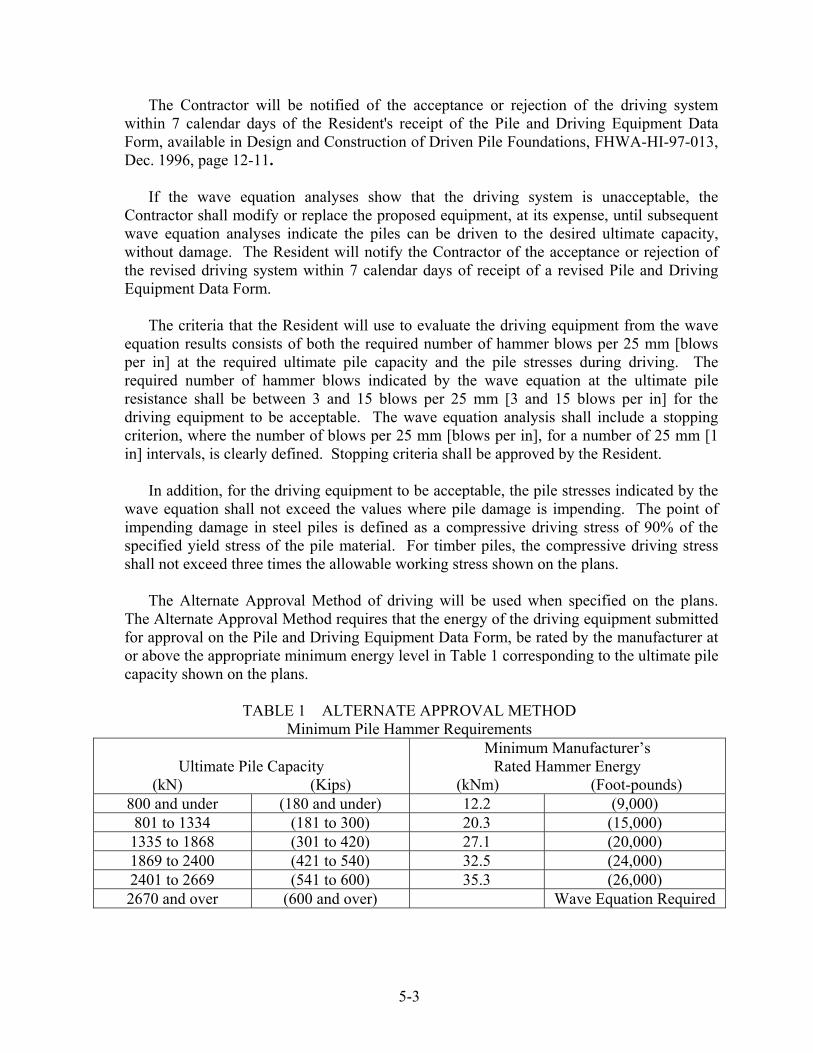
The Alternate Approval Method of driving will be used when specified on the plans.
The Alternate Approval Method requires that the energy of the driving equipment submitted for approval on the Pile and Driving Equipment Data Form, be rated by the manufacturer at or above the appropriate minimum energy level in Table 1 corresponding to the ultimate pile capacity shown on the plans.
TABLE 1 ALTERNATE APPROVAL METHOD
Minimum Pile Hammer Requirements
Ultimate Pile Capacity (kN) (Kips)
Minimum Manufacturer’s Rated Hammer Energy
(kNm) (Foot-pounds) 800 and under (180 and under) 12.2 (9,000) 801 to 1334 (181 to 300) 20.3 (15,000) 1335 to 1868 (301 to 420) 27.1 (20,000) 1869 to 2400 (421 to 540) 32.5 (24,000) 2401 to 2669 (541 to 600) 35.3 (26,000) 2670 and over (600 and over) Wave Equation Required
5-3

During pile driving operations, the Contractor shall use the approved system. No variations in the driving system will be permitted without the Resident's written approval. Any change in the driving system will be considered only after the Contractor has submitted a revised equipment data form. The Contractor will be notified of the acceptance or rejection of the driving system changes within 7 calendar days of the Resident's receipt of the requested change. The time required for submission, review, and approval of a revised driving system shall not constitute the basis for a contract time extension to the Contractor.
Acceptance of the pile driving equipment does not relieve the Contractor of the
responsibility to properly install the piling. The hammer acceptance and driving criteria will be based on commonly accepted hammer efficiencies, component properties, and soil parameters. Local soil conditions and the actual driving system will affect the driving. If in the opinion of the Resident, the accepted driving system fails to perform satisfactorily during actual driving, the Department reserves the right to revise the driving criteria.
Drive System Components and Accessories
Leads Pile driver leads shall be constructed in such a manner as to afford freedom of
movement of the hammer and to insure proper support of the pile during driving.
Followers Followers shall only be used when approved in writing by the Resident, or when specifically stated in the contract documents. In cases where a follower is permitted, the first pile in each group and every tenth pile driven thereafter shall be driven full length without a follower, to verify that adequate pile length is being attained to develop the desired pile capacity. The follower and pile shall be held and maintained in equal and proper alignment during driving. The follower shall be of such material and dimensions to permit the piles to be driven to the length determined necessary from the driving of the full-length piles. The final position and alignment of the first two piles installed with followers in each substructure unit shall be verified in accordance with location tolerances.
Hammer Cushion All power pile driving equipment shall be equipped with a
suitable thickness of hammer cushion material to prevent damage to the hammer and pile and to insure uniform driving behavior. Hammer cushions shall be made of durable, manufactured materials, provided in accordance with the hammer manufacturer's guidelines except that all wood, wire rope, and asbestos hammer cushions are specifically disallowed and shall not be used. A striker plate as recommended by the hammer manufacturer shall be placed on the hammer cushion to insure uniform compression of the cushion material. The hammer cushion shall be inspected in the presence of the Resident when beginning pile driving at each pile group or after each 100 hours of pile driving, whichever is less. Any reduction of hammer cushion thickness exceeding 25% of the original thickness shall be replaced by the Contractor before driving is permitted to continue.
Helmet Piles driven with power hammers require an adequate drive head to
distribute the hammer blow to the pile head. The helmet shall be axially aligned with the
5-4

hammer and the pile. The helmet shall be guided by the leads and not be free-swinging. The helmet shall fit around the pile head in such a manner as to prevent transfer of torsional forces during driving while maintaining proper alignment of hammer and pile.
For special types of piles, appropriate driving heads, mandrels, or other devices shall
be pro-vided in accordance with the manufacturer's recommendations so that the piles may be driven without damage.
501.04 Driving Procedures and Tolerances The sequence of driving piles in any unit shall be subject to the approval of the Resident. The ground surface shall be brought to the bottom of the footing elevation before driving the piles. The Contractor shall furnish all assistance required to make any observations and measurements. The order of placing individual piles in pile groups shall be either starting from the center of the group and proceeding outwards in both directions or starting at the outside row and proceeding progressively across the group. When driving is interrupted before final penetration is reached, data for the bearing capacity of the pile shall not be taken until at least 300 mm [12 in] of pile penetration is attained after driving has been resumed, or pile refusal has been attained. The heads of all piles shall be plane and perpendicular to the longitudinal axis of the pile before the helmet is attached. Approval of the hammer relative to driving stress damage shall not relive the Contractor of responsibility for piles damaged because of misalignment of the leads, failure of cushion materials, failure of splices, malfunction of the pile hammer, or improper construction methods. Piles damaged for such reasons shall be rejected and replaced at the Contractors expense when the Resident determines that the damage impairs the strength of the pile.
The compressive stresses in steel piles during driving shall not exceed 90% if the yield stress, determined by Wave equation Analysis or Dynamic Pile Analyzer.
Jetting Jetting shall be done only with the permission of the Resident and must be addressed in the Contractor’s SEWPCP. When water jets are used, the number of jets and the volume and pressure of the water at the nozzles shall be sufficient to erode freely the material adjacent to the piles. The plant shall have sufficient capacity to deliver at all times at least 690 kPa [100 psi] pressure at two 19 mm [¾ in] jet nozzles. Before the desired penetration is reached, the jets shall be withdrawn and the piles shall be driven with the hammer to the required penetration or bearing capacity.
Vibratory Hammers When permitted, piles initially driven using a vibratory hammer
shall be driven to the required capacity in accordance with the approved refusal criteria using a power hammer. When permitted, such equipment shall be used to installing production piles only after the pile tip elevation of the ultimate pile capacity is established by load testing and/or piles driven with an impact hammer. Vibratory hammers may be used to initially set a pile to a maximum distance of 6.1 m [20 ft] from the expected tip elevation, at which point a power hammer shall be employed. If the pile penetration rate is 300 mm [12 in] or less per minute, the use of a vibratory hammer should be discontinued and a
5-5

power hammer employed. When a battered pile is initially set using a vibratory hammer, the hammer shall be mounted in a set of leaders. The ultimate capacity of piles driven with vibratory hammers shall be based on the driving resistance recorded during impact driving after the vibratory equipment has been removed. Vibrated piles not attaining the ultimate pile capacity at the ordered length shall be spliced, as required, at the Contractors cost, and driven with an impact hammer until the ultimate pile capacity is achieved as indicated by the appropriate criteria in Section 501.07. When the ultimate pile capacity is attained, the remaining piles shall be installed to similar depth with similar vibratory hammer power consumption and rate of penetration as the first pile.
Preaugering When necessary to obtain the specified pile penetration and when
authorized by the Resident, the Contractor shall furnish the necessary drilling apparatus and drill holes, not greater that the least dimension of the pile top, to the proper depth and drive the piles therein. When specified in the contract documents, the Contractor shall prebore holes at pile locations and to the depths shown on the plans. Preaugered holes shall be of a size smaller than the diameter of diagonal of the pile cross section. If subsurface obstructions, such as boulders or rock layers are encountered, the hole diameter may be increase to the least dimension needed for pile installation. Any void space remaining around any type pile after driving shall be completely filled with sand or other approved material. The used of spuds, which are driven and removed to make a hole for inserting a pile, shall not be permitted in lieu of preboring.
Concrete shall not be placed in pipe piles until pile driving has progressed beyond a
radius of 5 m [15 ft] from the pile to be concreted. If pile heave is detected for pipe piles that have been filled with concrete, the piles shall be redriven to the original position after the concrete has attained sufficient strength and a proper hammer-pile cushion system, is in place as is satisfactory to the Resident.
Heaved Piles Piles that have heaved more than 5 mm [¼ in] during the driving of other
piles in a group shall be reseated to the required penetration or bearing capacity at the Contractor's expense.
Location and Alignment Tolerance The Contractor will be responsible to hold the piles
in place to allowable tolerances. Piles shall be driven with a variation of not more than 20 mm/m [¼ in/ft] from the vertical or from the batter shown on the plans. For piles that cannot be inspected for axial alignment internally after installation, an alignment check shall be made before installing the last 1.5 m [5 ft] of pile, or after installation is completed provided the exposed portion of the piles is not less than 1.5 m [5 ft] in length. The Resident may require that driving be stopped in order to check the pile alignment. Pulling laterally on piles to correct misalignment, or splicing a properly aligned section of a misaligned section shall not be permitted.
The cutoff elevation of piles for trestle bents shall not be out of position by more than 50
mm [2 in] from the dimensions shown on the plans. The cutoff elevation of piles, other than for trestle bents, shall not be out of position by more than 150 mm [6 in]. Actual embedment of the piles in the concrete shall be within 150 mm [6 in] of that shown on the plans. The as-driven
5-6

centroid of load of any group at cutoff elevation shall be within 5% of the plan location of the designated centroid of load. No pile shall be nearer than 100 mm [4 in] from any edge of the cap. Any increase in size of the pile cap to meet this edge distance requirement shall be at the Contractor’s expense. 501.05 Special Requirements for Steel Pipe Piles and Steel Casings Pipe piles shall be driven closed ended, unless otherwise specified. When open-ended pipe piles are specified or when the ends are not completely closed ended when driven, the inside of the pile shall be thoroughly cleaned out, and the inside walls cleaned by jetting or other means approved by the Resident. The sediment control form the cleaning operation shall be covered in the Contractor’s SEWPCP. Pipe piles shall be inspected and approved by the Resident immediately before concrete is placed. They shall be free from rupture and undue deformation and shall be free from water unless the Resident determines that the concrete can be placed without damage to the pile and such that the discharged water will be contained. The Contractor shall provide lights and other equipment necessary to inspect each pipe pile. Portland cement concrete for filling the pipe piles shall be placed in one continuous operation to fill the pile completely without causing water contamination. An internal type vibrator shall be used in the top 8 m [25 ft]. Pile heads shall be protected and cured in accordance with Section 502 - Structural Concrete. The placing of concrete and the driving of piles shall be scheduled so that fresh and setting concrete will not be injured by the pile driving. Steel casings shall be driven over H-beam piles through steel templates located inside the casings. A reinforcing steel cage, when specified, shall be placed inside the casings with a minimum of 50 mm [2 in] coverage and the casings shall be filled with concrete to the elevation shown on the plans. Full-length steel casings shall be used wherever practicable; however, splicing may be permitted when approved by the Resident. The method of splicing shall be as follows:
a. Steel casings shall be spliced by full penetration butt joint welds. b. When the casings are to be spliced while in a vertical position the welds shall be single-
bevel groove welds with the use of back-up rings. When the casings are to be spliced while in a horizontal position, the welds shall be single-vee groove welds with the use of back-up rings.
c. Welded joints shall conform to the Standard Details. Welding, including welder
qualifications, shall comply with the requirements of AWS D1.1, Structural Welding Code - Steel.
5-7
501.06 Defective Piles and Corrective Measures The procedure incident to the driving of piles shall not subject the piles to excessive and undue abuse causing deformation. Any pile damaged due to internal defects, improper driving, or driven below cutoff elevation, shall be considered defective and shall be corrected by and at the expense of the Contractor, by a method approved by the Resident. 501.07 Driven Pile Capacity, Pile Testing, and Acceptance Pile testing will be required as shown on the plans. Pile testing will be required to confirm that piles attain the required ultimate bearing capacity. A static load test consists of the application of a known load to the pile or group of piles and the accurate measurement of the resulting displacement. In the case of Steel Pipe Piles, no load shall be placed on the pile for at least 7 days after the concrete has been placed in the shell. Static loading testing shall be conducted under the direction of the Resident, but the Contractor shall furnish all labor and equipment. A dynamic load test consists of mounting instruments on the pile and accurately recording the output during driving using Pile Dynamic Analysis (PDA) equipment. On completion of either static or dynamic load testing, any test or anchor piling, not a part of the finished structure, shall be removed or cut off at least 300 mm [1 ft] below either the bottom of the footing or the finished ground elevation, whichever is lower.
Driven Pile Capacity - Wave Equation The piles shall be driven to the ultimate capacity as shown by the wave equation blows per 25 mm [blows/in] and the defined stopping criteria. The pile acceptance will be based on the ultimate pile capacity as determined by the wave equation analysis and the results of any dynamic or static pile tests, unless otherwise designated on the plans. When the Alternate Approval Method is specified on the plans, piles shall be driven to practical refusal of 10 blows per 25 mm [10 blows/in], or as approved by the Resident. Adequate pile penetration shall be considered to be obtained when the specified wave equation resistance criteria is achieved within 1.5 m [5 ft] of the pile toe elevation, based on ordered length. Piles not achieving the specified ultimate resistance within these limits shall be driven to penetration established by the Resident.
The wave equation resistance criteria will not be considered valid under any of the
following conditions:
a. The hammer or striking part does not have a free fall. b. The head of the pile becomes broomed or crushed. c. The penetration is not reasonably quick and uniform. d. There is an appreciable bounce after a blow. e. The hammer is operated outside the parameters recommended by the manufacturer.
5-8

Static Load Test When a static load test is specified in the contract documents, load tests shall be performed by procedures set forth in ASTM D1143 using the quick load test method except that the test shall be taken to plunging failure or the capacity of the loading system. Testing equipment and measuring systems shall conform to ASTM D1143, except that the loading system shall be capable of applying 150% of the ultimate pile capacity or 9000 kN [2023 kips], whichever is less, and that a load cell and a spherical bearing plate shall be used. The Contractor shall submit to the Resident for approval, detailed plans, prepared by a licensed Professional Engineer, of the proposed loading apparatus. The apparatus shall be constructed to allow the various increments of the load to be placed gradually without causing vibration to the test pile. When the approved method requires the use of tension (anchor) piles, such tension piles shall be of the same type and diameter as the production piles and shall be driven in the location of permanent piles when feasible, except that timber or tapered piles installed in permanent locations shall not be used as tension piles.
The design load shall be defined as 50% of the failure load. The failure load of a pile
tested under axial compressive load is that load which produces a settlement at failure of the pile head equal to:
METRIC UNITS
For piles less than or equal to 610 mm in diameter or width: Sf = S + (4.0 + 0.008D)
Where: Sf = Settlement at failure in millimeters D = Pile diameter or width in millimeters
S = Elastic deformation of total unsupported pile length in millimeters. For piles greater than 610 mm in diameter or width:
Sf = S + D/30 US CUSTOMARY UNITS
For piles less than or equal to 24 inches in diameter or width: Sf = S + (0.16 + 0.008D)
Where: Sf = Settlement at failure in inches D = Pile diameter or width in inches S = Elastic deformation of total unsupported pile length in inches.
For piles greater than 24 inches in diameter or width: Sf = S + D/30
The top elevation of the test pile shall be determined immediately after driving and again just before load testing to check for heave. Any pile that heaves more than 5 mm [¼ in] shall be redriven or jacked to the original elevation before testing. Unless otherwise specified in the contract, a minimum 3-day waiting period shall be observed between the driving of any anchor piles or the load test pile and the commencement of the load test.
Dynamic Pile Tests When a dynamic load test is specified in the contract documents,
dynamic measurements will be taken by the Contractor using procedures set forth in ASTM D-4945 during the driving of piles designated by the Resident as dynamic load test piles.
5-9

The dynamic tests are to be made by the Contractor’s Engineer who shall be a licensed Professional Engineer. The same Contractor’s Engineer conducting the wave equation analysis shall perform the dynamic load tests. Each test shall also include a CAPWAP analysis in order to closely model actual field conditions the Contractor’s Engineer shall be experienced in the used of the Pile Dynamic Analysis (PDA) equipment and its purpose related to pile capacity determinations. Dynamic measurements shall be reported to the Resident and include items specified in Section 7 of ASTM D4945.
Before placement of the pile in the leads, the Contractor shall make the designated pile
available for obtaining wave speed measurements and for predrilling the required instrument attachment holes. Predriving wave speed measurements will not be required for steel piles. When wave speed measurements are made, the piling shall be in a horizontal position and not in contact with other piling. The Contractor will furnish the equipment, materials, and labor necessary for drilling holes in the piles for mounting the instruments. The instruments will be attached near the head of the pile with bolts placed through drilled holes on the steel piles or with wood screws for timber piles.
The Contractor shall provide the Contractor’s dynamic testing engineer with reasonable
means of access to the pile for attaching instrument after the pile is place in the leads. The Contractor shall furnish electric power for the dynamic test equipment. The power supply at the outlet shall be 10 amp, 115 volt, 55-60 cycle, A.C. only. Field generators used as the power source shall be equipped with functioning meters for monitoring voltage and frequency levels.
With the dynamic testing equipment attached, the Contractor shall drive the pile to the
depth at which the dynamic test equipment indicates that the ultimate pile capacity, as called for on the plans, has been achieved, unless directed otherwise by the Resident. The stresses in the piles will be monitored during driving with the dynamic test equipment to ensure that the values determined do not exceed the allowable values in Section 501.04. If necessary, the Contractor shall reduce the driving energy transmitted to the pile by using additional cushions or reducing the energy output of the hammer in order to maintain stresses at or below the allowable values. If non-axial driving is indicated by dynamic test equipment measurements, the Contractor shall immediately realign the driving system.
When directed to retap by the Resident, the Contractor shall wait up to 24 hours and,
after the instruments are reattached, retap (redrive) the dynamic load test pile. A cold hammer shall not be used for the redrive. The hammer shall be warmed up before redrive begins by applying at least 20 blows to another pile. The maximum amount of penetration required during redrive shall be 150 mm [6 in] or the maximum total number of hammer blows required will be 50, whichever occurs first. After retapping, the Resident will either provide the cutoff elevation or specify additional pile penetration and testing. The Contractor shall supply the Resident with a report of the test results of each dynamically tested pile and a CAPWAP analysis within ten days of the completion of testing.
Ultimate Pile Capacity Piles shall be driven by the Contractor to the penetration depth
shown on the plans or to a greater depth if necessary to obtain the ultimate pile capacity.
5-10
The ultimate pile capacity shall be determined by the Engineer based on one of the methods listed in Section 501.07. The ultimate capacity of piles driven with vibratory hammers shall be based on the criteria in Section 501.04
501.08 Test Piles (Indicator Piles) When required, test piles shall be driven as shown on the plans at the locations and to the lengths specified by the Resident. This work shall be accomplished before pile driving is allowed to commence. All test piles shall be driven with power hammers unless specifically stated otherwise in the plans. In general, the specified length of test piles will be greater than the estimated length of production piles in order to provide for variation in soil conditions. The driving equipment used for driving test piles shall be identical to that which the Contractor proposed to use on the production piling. Driving equipment shall conform to the requirements of Section 501.03. The Contractor shall bring the ground at each test pile to the elevation of the bottom of the footing before the pile is driven. Test piles shall be driven to the driving resistance corresponding to ultimate capacity, as determined with the wave equation by the Resident, at the estimated tip elevation. Test piles that do not attain the hammer blow count specified above at a depth of 300 mm [1 ft] below the estimated tip elevation shown on the plans shall be allowed to "set up" for 24 hours, before being redriven. A cold hammer shall not be used for redrive. The hammer shall be warmed up before driving begins by applying at least 20 blows to another pile. If the specified hammer blow count is not attained on redriving, the Resident may direct the Contractor to drive a portion or all of the remaining test pile length and repeat the "set up" redrive procedure. If the specified hammer blow count is not attained on redriving and the full length of the pile had been driven, the Contractor shall splice and drive additional pile as directed by the Resident. 501.09 Splicing Piles Full-length piles shall always be used wherever practicable. When splices are unavoidable for piles, their number, locations and details shall be subject to approval of the Resident. If full-length piles cannot be used, piles shall not be spliced unless approved by the Resident. Piles fabricated from multiple pieces will be acceptable only if they comply with the following: Piles lengths up to and including 6 m [20 ft] long - no splices allowed.
Piles lengths over 6 m up to and including 12 m [20 ft to 35 ft] - 1 splice, maximum, per pile. Piles lengths over 12 m up to and including 24 m [35 ft to 79 ft] - 2 splices, maximum. For pile lengths exceeding 24 m [79 ft], one splice per 12 meters [40 ft] will be permitted. Sections less than 3 m [10 feet] in length will not be spliced except as a final (top) section of the pile.
When pre-planned splicing is permitted, the pile piece of lesser length shall be placed at the tip of the pile (the first part of the pile that enters the ground).
When splicing is authorized, piles shall be spliced as follows:
5-11
a. Damaged material shall be removed from the end of the driven pile. The ends of both sections to be spliced shall be cut off square with the longitudinal axis of the pile and scarifed as required. All cutting shall be done with the use of a mechanical guide and no free hand cutting will be allowed except for minor trimming.
b. A full penetration butt weld shall be used for the entire cross section of the pile. c. All welding shall comply with the requirements of Section 504 - Structural Steel,
except as modified hereinafter.
1. No run-off tabs will be required for flange butt welds on H-beam Piles. 2. No welding shall be done when the temperature in the immediate vicinity of the
weld is below -20°C [0°F]; when the surfaces are damp or exposed to rain, snow, or high wind; or when the welders or welding operators are exposed to inclement conditions.
3. The pile shall be preheated to and maintained at 65°C [150°F] minimum within 150 mm [6 in] from the weld while welding.
4. The maximum electrode size shall be 4.76 mm [3/16 in]. 5. Formal welding procedures need not be submitted.
d. Welders shall be prequalified in accordance with Section 504 - Structural Steel. e. The Contractor may use mechanical splices, if approved by the Resident, and if the
splice can transfer the full pile strength in bending, compression, and tension. Any alternate splices, so authorized, shall be capable of developing the full bending strength of the pile on both the x-x and y-y axis. If an H-pile splice incorporates a prefabricated pile splicer, the splicer shall be installed and welded as recommended by the manufacturer of the splices and shall be supplemented with a partial penetration groove weld on each flange with a 45° bevel on the upper member of the splice and a groove depth of approximately 75% of the nominal flange thickness (AWS D1.1, BTC-P4-GF). All welding shall conform to the requirements of (c) above.
501.10 Prefabricated Pile Tips Steel H-beam piles shall be equipped with cast steel prefabricated pointed pile tips attached to the pile with a 8 mm [5/16 in] groove weld or equivalent along each flange. Welding shall be done using low-hydrogen electrodes and the base metal shall be preheated to 65°C [150°F] minimum. Unless otherwise shown on the plans, steel pipe piles shall have pointed cast steel pile tips, welded as above specified for H-beam pile tips. Pile tips for both H-beam and pipe piles shall be approved by the Resident. Pile tips may be welded to the piles either by the supplier of the piles or in the field by the Contractor, at its option.
5-12

501.11 Method of Measurement
a. Equipment Mobilization A lump sum price bid for mobilization shall include the cost of furnishing all labor, materials, and equipment necessary for the transporting, erecting, dismantling, and removing the entire pile driving equipment.
b. Piles Furnished The unit of measurement for furnishing casings, timber, and steel shall be the meter [linear foot]. The quantity to be paid for will be the sum of the lengths in meters [feet] of the piles, of the types and lengths ordered in writing by the Resident. No allowance will be made for the length of piles, including test piles furnished by the Contractor, to replace piles that were previously accepted by the Resident, but are subsequently damaged prior to completion of the contract. When extensions of piles are necessary, the extension length ordered in writing by the Resident will be included in the length of piling furnished. All piles must be cutoff at the cutoff elevation shown on the plans. If the piles are cutoff at a higher elevation, the portion between these elevations will be deducted from this Item.
c. Piles in Place Initiation of pile installation by use of a vibratory hammer, preboring,
jetting or other methods used for facilitating pile driving procedures will not be measured and payment shall be considered included in the unit price bid for the Piles Driven pay item.
The quantity of H-beam, cast-in-place pipe or shell concrete piles to be paid for will be
the actual number of meters [linear feet] of steel pipe or shell piles driven, cast, and left in place in the completed and accepted work. Measurements will be made from the tip of the steel pipe, shell pile, or H-beam pile to the cutoff elevation as shown on the plans.
Unused pile cutoffs 6 m [20 ft] or more in length will remain the property of the
Department and will be stored at a bridge maintenance yard nearest the project. Hauling and unloading of piles will be done by the Contractor or by the Department, depending upon availability of services.
When hauling and unloading is done by the Contractor, payment will be made under the
provisions of Section 109 - Changes. There will be no separate payment to load piles at the project site; loading will be considered an incidental cost to the item.
The following are the locations and contact telephone numbers of all bridge maintenance
yards throughout the State:
Division 1 New Limerick Tel # 764-2060 Division 2 Hancock Tel # 667-5556 Division 3 Carmel Tel # 941-4553 Division 4 Skowhegan Tel # 453-7377 Division 5 Washington Tel # 596-2230 Division 6 Scarborough Tel # 883-5546 Division 7 Farmington Tel # 562-4228
The Resident will contact the Bridge Maintenance Managers at the above listed telephone numbers so that proper arrangements can be made for delivery.
5-13

No separate measurement will be made for reinforcing steel, excavation, drilling, cleaning of drilled holes, drilling fluids, sealing materials, concrete, required casing, and other items required to complete the work.
d. Pile Tips Pile Tips will be measured by the number of tips authorized and
satisfactorily installed. e. Pile Splices- Pile splices will be measured by the number of splices authorized and
satisfactorily completed to drive the piles in excess of the ordered length furnished and approved by the Resident.
f. Loading tests Load tests will be measured by the number of unit tests authorized and
satisfactorily made. g. Dynamic Load Test Dynamic load tests will be measured by the number of dynamic
pile tests authorized and satisfactorily made. One dynamic test includes all data collected on one pile during both the initial pile driving and a retap done up to 24 hours after the initial driving
501.12 Basis of Payment. The accepted quantities of piles and casings will be paid for at the
contract unit price per meter [linear foot], delivered, and complete in place. Such payment will include full compensation for any necessary excavation or backfilling required after driving, to bring the foundation area to the correct elevation.
Pile cutoffs and concrete for pipe piles and casings will not be paid for separately but will be considered as incidental to the related Pay Items. Damaged pile lengths removed for pile splicing will be considered incidental to the related Pay Items. Excavating and cleaning steel pipe piles and steel casings, furnishing and placing reinforcing steel and steel templates in steel pipe piles and steel casings will not be paid for separately, but will be considered as incidental to the related Pay Items.
Preboring, jetting or other methods used to facilitate the driving of piling wall not be paid for separately, but will be considered incidental to the contract pay item for pile in place
Full compensation for all jetting, drilling, providing special driving tips or heavier sections for steel piles or shells, or other work necessary to obtain the specified penetration and bearing value of the piles, for drilling holes through embankment and filling the space remaining around the pile with sand or pea gravel, for disposing of material resulting from drilling holes, and for all excavation and backfill involved in constructing concrete extensions as shown on the plans, and as specified in these specifications and the special provisions, and as directed by the Engineer shall be considered as included in the contract unit price paid for drive pile or in the contract price paid per meter for cast-in-drilled-hole concrete piling, and no additional compensation will be allowed therefore.
5-14
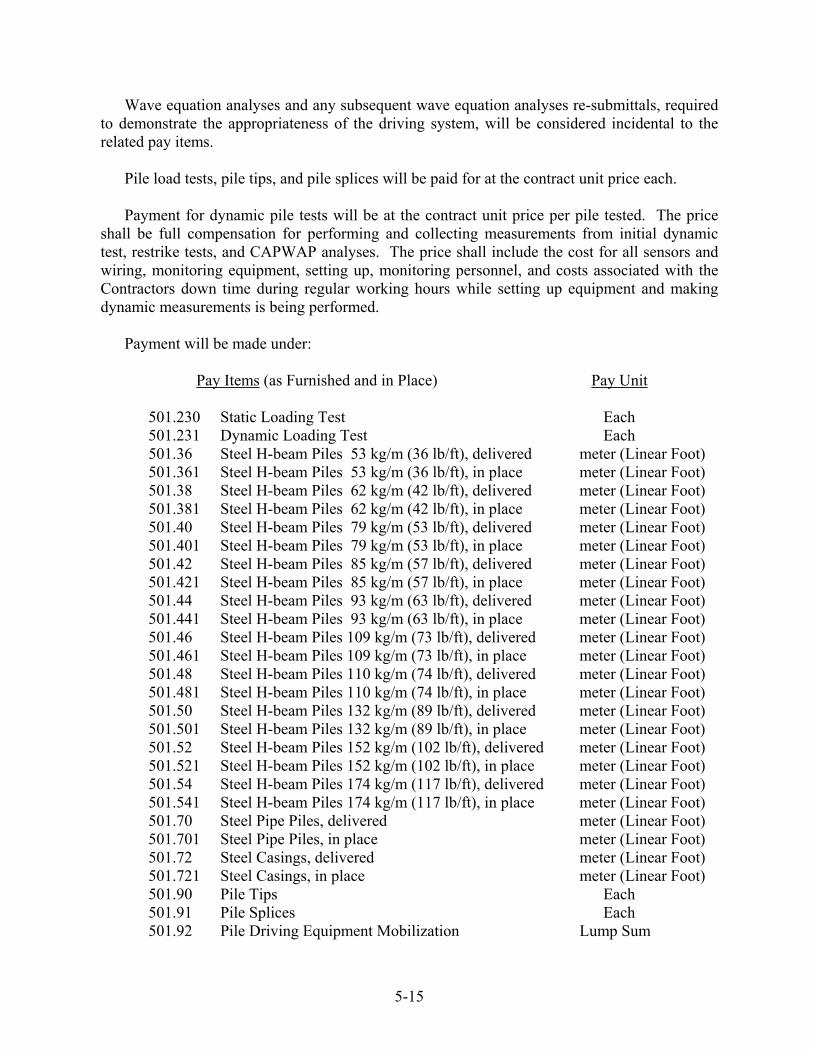
Wave equation analyses and any subsequent wave equation analyses re-submittals, required to demonstrate the appropriateness of the driving system, will be considered incidental to the related pay items. Pile load tests, pile tips, and pile splices will be paid for at the contract unit price each.
Payment for dynamic pile tests will be at the contract unit price per pile tested. The price shall be full compensation for performing and collecting measurements from initial dynamic test, restrike tests, and CAPWAP analyses. The price shall include the cost for all sensors and wiring, monitoring equipment, setting up, monitoring personnel, and costs associated with the Contractors down time during regular working hours while setting up equipment and making dynamic measurements is being performed. Payment will be made under:
Pay Items (as Furnished and in Place) Pay Unit 501.230 Static Loading Test Each 501.231 Dynamic Loading Test Each 501.36 Steel H-beam Piles 53 kg/m (36 lb/ft), delivered meter (Linear Foot) 501.361 Steel H-beam Piles 53 kg/m (36 lb/ft), in place meter (Linear Foot) 501.38 Steel H-beam Piles 62 kg/m (42 lb/ft), delivered meter (Linear Foot) 501.381 Steel H-beam Piles 62 kg/m (42 lb/ft), in place meter (Linear Foot) 501.40 Steel H-beam Piles 79 kg/m (53 lb/ft), delivered meter (Linear Foot) 501.401 Steel H-beam Piles 79 kg/m (53 lb/ft), in place meter (Linear Foot) 501.42 Steel H-beam Piles 85 kg/m (57 lb/ft), delivered meter (Linear Foot) 501.421 Steel H-beam Piles 85 kg/m (57 lb/ft), in place meter (Linear Foot) 501.44 Steel H-beam Piles 93 kg/m (63 lb/ft), delivered meter (Linear Foot) 501.441 Steel H-beam Piles 93 kg/m (63 lb/ft), in place meter (Linear Foot) 501.46 Steel H-beam Piles 109 kg/m (73 lb/ft), delivered meter (Linear Foot) 501.461 Steel H-beam Piles 109 kg/m (73 lb/ft), in place meter (Linear Foot) 501.48 Steel H-beam Piles 110 kg/m (74 lb/ft), delivered meter (Linear Foot) 501.481 Steel H-beam Piles 110 kg/m (74 lb/ft), in place meter (Linear Foot) 501.50 Steel H-beam Piles 132 kg/m (89 lb/ft), delivered meter (Linear Foot) 501.501 Steel H-beam Piles 132 kg/m (89 lb/ft), in place meter (Linear Foot) 501.52 Steel H-beam Piles 152 kg/m (102 lb/ft), delivered meter (Linear Foot) 501.521 Steel H-beam Piles 152 kg/m (102 lb/ft), in place meter (Linear Foot) 501.54 Steel H-beam Piles 174 kg/m (117 lb/ft), delivered meter (Linear Foot) 501.541 Steel H-beam Piles 174 kg/m (117 lb/ft), in place meter (Linear Foot) 501.70 Steel Pipe Piles, delivered meter (Linear Foot) 501.701 Steel Pipe Piles, in place meter (Linear Foot) 501.72 Steel Casings, delivered meter (Linear Foot) 501.721 Steel Casings, in place meter (Linear Foot) 501.90 Pile Tips Each 501.91 Pile Splices Each 501.92 Pile Driving Equipment Mobilization Lump Sum
5-15
SECTION 502 - STRUCTURAL CONCRETE
502.01 Description This work shall consist of furnishing and placing Portland Cement Concrete for structures and incidental construction in accordance with these Specifications and in conformity with the lines, grades, and dimensions shown on the Plans or established, or for placing concrete fill for foundations where called for on the Plans. For METHOD A Statistical Acceptance, or METHOD B Small Quantity Product Verification, the work shall conform to the Contractor’s approved Quality Control (QC) Plan and Quality Assurance (QA) provisions, in accordance with these Specifications and the requirements of Section 106 - Quality. For METHOD C, the work shall conform to the requirements of this specification and Section 106- Quality. 502.02 Classification The Portland Cement Concrete shall be the class indicated on the Plans.
502.03 Materials Materials shall meet the requirements specified in the following Sections of Division 700 Materials: Portland Cement and Portland Pozzolan Cement 701.01 Water 701.02 Air Entraining Admixtures 701.03 Water Reducing Admixtures 701.04 Water Reducing, High Range Admixture 701.0401 Set Retarding Admixtures 701.05 Curing Materials 701.06 Water stops 701.07 Smoothed Surfaced Asphalt Roll Roofing (Formerly
Heavy Roofing Felt) 701.08
Fly Ash 701.10 Calcium Nitrite Solution 701.11 Silica Fume 701.12 Ground Granulated Blast Furnace Slag 701.13 Fine Aggregate for Concrete 703.01 Coarse Aggregate for Concrete 703.02 Alkali Silica Reactive Aggregates 703.0201 Preformed Expansion Joint Filler 705.01 Bridge Drains 711.04
502.04 Shipping and Storage Cement may be shipped in bags or in bulk from pre-tested and approved silos at the cement mill. The cement shall be completely protected from rain and moisture. Any cement damaged by moisture or which fails to meet any of the specified requirements shall be rejected and removed from the site. If requested by the Resident, cement stored for a period longer than 60 days shall be retested before being used in the work. Bags of cement in shipment or storage shall not be piled more than 8 bags high. Bags of cement which for any reason have become partially set or which contain lumps of caked cement
5-16
shall be rejected. Shipments of cement in bags shall be separately stored in a manner as to provide easy access for identification and inspection of each shipment. Fly ash and Slag shall be stored in weather tight silos approved by the Resident. All silos shall be completely empty and clean before material is deposited therein, unless the silo already contains material of the same type and properties. Fly ash or Slag remaining in bulk storage for a period greater than one year after completion of tests will be resampled and retested by the Department before shipment or use. Handling, shipping and stockpiling of aggregates shall be done in such a way as to minimize segregation and breakage. Fine aggregate and each size of coarse aggregate shall be stored in completely separate stockpiles on prepared bases constructed of the same material as that to be stockpiled, with a minimum thickness of 300 mm [1 ft]. The ground under the prepared bases shall be reasonably graded to drain away from the stockpile and shall be free of brush or other harmful vegetation. The base shall be left in place, undisturbed for the duration of the use of the stockpile. Prepared bases can be salvaged for reuse provided this material is reprocessed. Barge floors, wood, metal or other approved hard surfaces shall be considered acceptable alternates for the prepared bases described above. 502.041 Testing Equipment The Contractor shall provide test equipment and materials as specified below for use by the Resident or their representative exclusively. The equipment shall be available and acceptable to the Resident one week prior to placing any concrete. All costs associated with providing and maintaining testing equipment shall be considered incidental to the work and no additional payment will be made. The Resident will maintain the test equipment in reasonable condition. However, the Contractor shall replace any equipment that becomes unusable due to normal wear and tear or which is stolen or damaged from other than the Resident's neglect or mistreatment. All such replacement costs shall be considered incidental to the work and no additional payment will be made. A. Pressure Air Meter meeting requirements of AASHTO T152 (Type B) and all accessory pay items required for use with the particular design of apparatus. This shall include one 225 mm [9 in] mason trowel, one metal scoop 225 mm long x 125 mm wide [9 in long x 5 in wide], one tamping rod conforming to AASHTO T119, one rubber mallet as described in AASHTO T152, one strike off bar (flat straight bar of steel). The air meter shall be functional and shall bear a current calibration certificate issued by a recognized testing laboratory. Current shall mean within the calendar year. B. Two pocket dial thermometers -20°C to +95°C, [0ºF to 200ºF] 25 mm [1 in] diameter dial, 125 mm [5 in] pointed stem, unbreakable poly carbonate crystal, stainless steel case, stem and bezel. Accuracy required is 1 percent over entire range.
5-17
C. "Contractors" rubber tired wheelbarrow. D. Two D-handle square end shovels 240 mm wide [9 ½ in]. E. Two pair heavy duty, long cuff, rubber gloves. F. Miscellaneous equipment: 500 mL [16 oz] plastic squeeze bottle, 19 L [5 gal] bucket, scrub brush, paper towels, folding rule, and rubber syringe. G. Small rod - one tamping rod conforming to AASHTO T277. H. 3 meter [10 ft] straightedge as required by Resident.
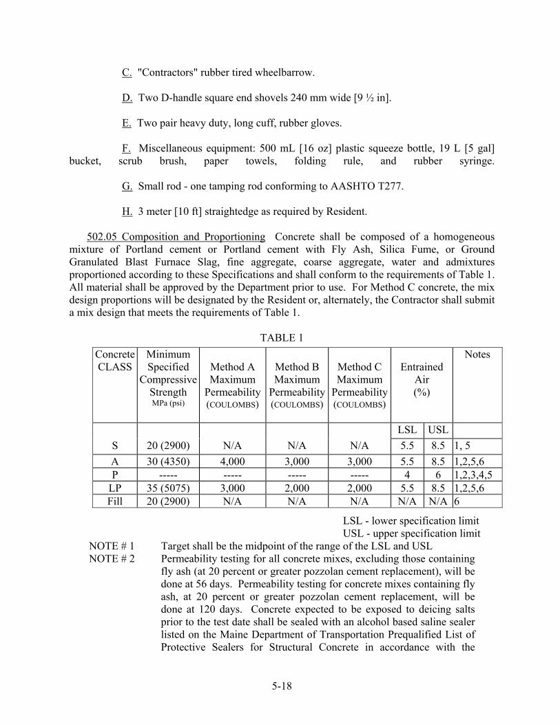
502.05 Composition and Proportioning Concrete shall be composed of a homogeneous mixture of Portland cement or Portland cement with Fly Ash, Silica Fume, or Ground Granulated Blast Furnace Slag, fine aggregate, coarse aggregate, water and admixtures proportioned according to these Specifications and shall conform to the requirements of Table 1. All material shall be approved by the Department prior to use. For Method C concrete, the mix design proportions will be designated by the Resident or, alternately, the Contractor shall submit a mix design that meets the requirements of Table 1.
TABLE 1 Concrete CLASS
Minimum Specified
Compressive Strength MPa (psi)
Method A Maximum
Permeability(COULOMBS)
Method B Maximum
Permeability(COULOMBS)
Method C Maximum
Permeability(COULOMBS)
Entrained
Air (%)
Notes
LSL USL S 20 (2900) N/A N/A N/A 5.5 8.5 1, 5 A 30 (4350) 4,000 3,000 3,000 5.5 8.5 1,2,5,6 P ----- ----- ----- ----- 4 6 1,2,3,4,5
LP 35 (5075) 3,000 2,000 2,000 5.5 8.5 1,2,5,6Fill 20 (2900) N/A N/A N/A N/A N/A 6
LSL - lower specification limit USL - upper specification limit
NOTE # 1 Target shall be the midpoint of the range of the LSL and USL NOTE # 2 Permeability testing for all concrete mixes, excluding those containing
fly ash (at 20 percent or greater pozzolan cement replacement), will be done at 56 days. Permeability testing for concrete mixes containing fly ash, at 20 percent or greater pozzolan cement replacement, will be done at 120 days. Concrete expected to be exposed to deicing salts prior to the test date shall be sealed with an alcohol based saline sealer listed on the Maine Department of Transportation Prequalified List of Protective Sealers for Structural Concrete in accordance with the
5-18

manufacturer’s recommendation, at no additional cost to the Department.
NOTE # 3 Calcium Nitrite shall be added at the rate of 14.85 L/m³ [3 gallons per cubic yard].
NOTE # 4 Strength and permeability requirements will be shown on the Plans. NOTE # 5 NOTE # 6
Compressive strength testing for all concrete mixes, excluding those containing fly ash (at 20 percent or greater pozzolan cement replacement), will be done at 28 days. Compressive strength testing for concrete mixes containing fly ash, at 20 percent or greater pozzolan cement replacement, will be done at 56 days. Coarse aggregate for concrete shall meet the requirements of Section 703.02 for Class “A” or “AA”.
At least 30 days prior to the first placement, a concrete mix design shall be submitted by the Contractor to the Department for approval. No concrete shall be placed on a project until the concrete mix design is approved by the Department. Once the design has been approved, the Contractor shall conduct a trial batch at the concrete plant utilizing transit mixers at the plant. The Contractor shall submit four clearly identified 100 mm diameter x 200 mm high [4 in diameter x 8 in high] cylinders to the Department at least 30 days prior to the first placement for permeability testing. Full documentation shall be submitted with the cylinders and must include actual batch weights and all concrete test properties. The Contractor may submit the trial batch cylinders with the mix design. The cylinders shall be submitted between the ages of 2 and 7 days. Subsequent use of an approved design will not require this trial batch. For Method C concrete, trial batching is not required. The mix design submitted by the Contractor shall include the following information:
A. Description of individual coarse aggregate stockpiles, original source, bulk specific gravity, absorption, gradation, and alkali silica reactivity test results. A combined coarse aggregate blended gradation shall be provided.
B. Description of fine aggregate, original source, bulk specific gravity, absorption,
colorimetric, gradation and Fineness Modulus (F.M.). C. Description and amount of cement and pozzolanic material. D. Target water cement ratio.
E. Target water content by volume. F. Target strength. G. Target air content, slump and concrete temperature.
5-19
H. Target concrete unit weight. I. Type and dosages of air entraining and chemical admixtures. J. Target Coulomb Value
Approval by the Department will be contingent upon the ability of the mix design proportions to produce concrete strength requirement and other factors that affect durability. Pozzolans are included as cementitious material. Concrete mix designs shall contain not more than 30 percent fly ash or 50 percent slag pozzolan cement replacement, by weight. Cast-in-place concrete shall contain not more than 377 kg/m3 [635 lb/yd3] of cement and not more than 392 kg/m3 [660 lb/yd3] of cementitious material. All concrete mixes must be designed in accordance with the criteria of this Section. The design proportions with the fine aggregates designated as a percent of the total aggregate must be stated in terms of aggregates in a saturated, surface dry condition and the batch weights will be adjusted by the Contractor for the actual moisture of the aggregate at the time of use.
No change in the source or character of the mix ingredients may be made without notice to the Resident and no new mix ingredients shall be used until the Resident has approved such ingredients and new mix proportions, if they change. 502.0501 Quality Control METHOD A, METHOD B and Method C The Contractor shall control the quality of the concrete through testing, inspection, and practices which shall be described in the Quality Control Plan, hereinafter referred to as the “QC Plan”, sufficient to assure a product meeting the Contract requirements. The QC Plan shall meet the requirements of Section 106 - Quality and this specification. No QC Plan is required for Method C concrete. No work under this item shall proceed until the QC Plan is submitted to and approved by the Resident. Concrete sampling for QC shall be taken at the discharge point with pumped concrete sampling taken at the discharge end of the pump line. The QC Plan shall address all elements that affect the quality of the structural concrete including, but not limited to, the following:
A. Mix Design(s) B. Aggregate Production C. Quality of Components D. Stockpile Management E. Proportioning, including Added Water F. Mix and Transportation, including Time from Batching to Completion of Delivery
5-20

G. Initial and as Delivered Mix Properties, including Temperature, Air Content, Consistency and Water Cement Ratio
H. Process Quality Control Testing I. Placement and Consolidation J. Permeability K. Compressive Strength L. Finishing and Curing M. Hot and Cold Weather Concreting Procedures, including curing and form removal
The QC Plan under METHOD A shall include the names and specific qualifications of the individuals meeting these requirements and qualifications: A. Plan Administrator meeting one of the following qualifications:
1. Professional Engineer registered in the State of Maine with one year of concrete experience acceptable to the Department.
2. Engineer-in-Training certified by the State of Maine with two years of concrete experience acceptable to the Department.
3. An individual with three years concrete experience acceptable to the Department and with a Bachelor of Science Degree in Civil Engineering or a related Civil Engineering Technology discipline.
4. Construction Materials Technician certified at Level III by the National Institute for Certification in Engineering Technologies (NICET).
5. Highway Materials Technician certified at Level III by NICET.
6. Highway Construction Technician certified at Level III by NICET.
7. A NICET certified engineering technician in Civil Engineering Technology with five years of concrete experience acceptable to the Department.
8. A Maine Concrete Technician Certification Board [MCTCB] certified engineering technician with 5 years concrete experience acceptable to the Department.
9. A New England Transportation Technician Certification Program [NETTCP] certified concrete technician with 5 years concrete experience acceptable to the Department.
B. Process Control Technician(s) (PCT) shall utilize test results and other quality control practices to assure the quality of aggregates and other mix components and control proportioning to meet the mix design(s). The QC Plan shall detail the frequency of sampling and testing, corrective actions to be taken, and documentation. The PCT shall periodically
5-21

inspect all equipment utilized in proportioning and mixing to assure it is operating properly and that proportioning and mixing conforms to the mix design(s) and other Contract requirements. The QC Plan shall detail how these duties and responsibilities are to be accomplished and documented and whether more than one PCT is required. The QC Plan shall include the criteria utilized by the PCT to correct or reject unsatisfactory materials. The PCT shall be a MCTCB certified concrete plant technician or a NETTCP certified concrete technician.
C. Quality Control Technician(s) (QCT) shall perform and utilize quality control tests at
the job site to assure that delivered materials meet the requirements of the mix design(s), including temperature, water/cement ratio, air content, permeability and strength. The QCT shall inspect all equipment utilized in transporting, placing, consolidating, finishing, and curing to assure it is operating properly and that placement, consolidation, finishing, and curing conform to the Contract requirements. The QC Plan shall detail frequency of sampling and testing, corrective actions to be taken, and documentation. The QC Plan shall detail how these duties and responsibilities are to be accomplished and documented, and whether more than one QCT is required. The QC Plan shall include the criteria utilized by the QCT to reject unsatisfactory materials. The QCT shall a MCTCB certified concrete field technician or a NETTCP certified concrete technician. D. The Plan shall detail the coordination of the activities of the Plan Administrator, the PCT and the QCT.
The QC Plan under METHOD B shall include the name and specific qualifications of the technician meeting the following requirements:
Quality Control Technician(s) (QCT) shall perform and utilize quality control tests at the job site to assure that delivered materials meet the requirements of the mix design(s), including temperature, water/cement ratio, air content, permeability and strength. The QCT shall inspect all equipment utilized in transporting, placing, consolidating, finishing, and curing to assure it is operating properly and that placement, consolidation, finishing, and curing conform to the Contract requirements. The Contractor shall detail frequency of sampling and testing, corrective actions to be taken, and documentation. The Contractor shall include the criteria utilized by the QCT to reject unsatisfactory materials. The QCT shall meet one of the PCT qualifications above, or shall be a MCTCB certified concrete field technician.
Under METHOD A, METHOD B and METHOD C the Contractor shall provide a Certificate of Compliance for each truckload of concrete to the Department at the time of the load placement. The Certificate of Compliance shall be a form acceptable to the Department and shall include:
Contract Name & Number Bridge Name Manufacturing Plant (Batching Facility) Name of Contractor (Prime Contractor) Date Time Batched/Time Discharged
5-22

Truck No. Quantity (Quantity Batched this Load) Type of Concrete by Class and Producer Design Mix No. Cement Brand or Type, and Shipment Certification No. Temperature of Concrete at Discharge Target Weights per cubic meter [cubic yard] and Actual Batched Weights for:
1. Cement 2. Pozzolanic Additives, including Fly Ash, Slag Cement, and Microsilica 3. Coarse Concrete Aggregate 4. Fine Concrete Aggregate 5. Water (including free moisture in aggregates and water added at the project) 6. Admixtures Brand and Quantity (ml/cubic meter [fl. oz./cubic yard])
Air-Entraining Admixture Water Reducing Admixture Other Admixtures Placement Location
The Contractor shall maintain records of all QC tests and calculations. The gradation test data and results shall be reported to the Department before the placement they represent. The compressive strength test results shall be reported to the Department by 10:00 A.M. of the first working day following the test. All QC test data shall be signed by the person who performed the test. The Contractor shall record all on site QC test data and calculations at the time of the placement and present this information, on a form acceptable to the Department, to the Department by 10:00 A.M. of the first working day following the concrete placement. All Method A Quality Control testing shall meet the minimum requirements found in Table 2.
TABLE 2 METHOD A MINIMUM QUALITY CONTROL TESTING REQUIREMENTS
TEST TEST METHOD SAMPLING
LOCATIONFREQUENCY
Gradation AASHTO T-27 & T-11 Stockpile One set per mix before production. One set every 120m3 [155 yd3] Min. 1 set per month
Organic Impurities AASHTO T-21 Stockpile One set per each FA gradation
% Absorption AASHTO T-84 & T-85 Stockpile Once per aggregate per 6 months
Specific Gravity AASHTO T-84 & T-85 Stockpile Once per aggregate per 6 months
Total Moisture in Agg. AASHTO T-255 Stockpile One set per day’s production
Free Water and Agg. Wt.
N/A One per day’s production per design
5-23

% Entrained Air AASHTO T-152 On Project On first two loads and every third load thereafter
Compressive Strength AASHTO T-22 On Project One set per sublot
Compressive Strength AASHTO T-22 @ 7days
On Project One set per sublot
502.0502 Quality Assurance METHOD A The Department will determine the acceptability of the concrete through a quality assurance program. The Department will take Quality Assurance samples a minimum of once per sublot on a statistically random basis. Quality Assurance tests will include compressive strength, air content and permeability. Concrete sampling for quality assurance tests will be taken at the discharge point, with pumped concrete sampling taken at the discharge end of the pump line.
Lot Size A lot size shall consist of the total quantity represented by each class of concrete in the Contract, except in the case when the same class of concrete is paid for under both lump sum items and unit price items in the Contract; in this case, the lump sum item quantities shall comprise 1 lot and the unit price item quantities shall comprise a separate lot. A lot shall consist of a minimum of 3 and a maximum of 10 sublots. If a lot is comprised of more than 10 sublots, sized in accordance with Table #3, then this quantity shall be divided equally into 2, or more, lots such that there is a minimum of 3 and a maximum of 10 sublots per lot. If there is insufficient quantity in a lot to meet the recommended minimum sublot size, then the lot shall be divided into 3 equal sublots.
Sublot Size, General The size of each sublot shall be determined in accordance with Table #3. The Resident may vary sublot sizes based on placement sizes and sequence.
Sublot Size, Unit Price Items Sublot sizes will initially be determined from estimated quantities. When the actual final quantity of concrete is determined: If there is less than one-half the estimated sublot quantity in the remaining quantity, then this quantity shall be combined with the previous sublot, and no further Acceptance testing will be performed; if there is more than one-half the estimated sublot quantity in the remaining quantity, then this quantity shall constitute the last sublot and shall be represented by Acceptance test results. If it becomes apparent part way through a lot that, due to an underrun in quantity, there will be an insufficient quantity of concrete to comprise three sublots, then the Resident may adjust the sizes of the remaining sublots and select new sample locations based on the revised estimated quantity of concrete remaining in the lot.
Sublot Size, Lump Sum Items Each lot shall be divided into sublots of equal size, based on the estimated quantity of concrete.
5-24
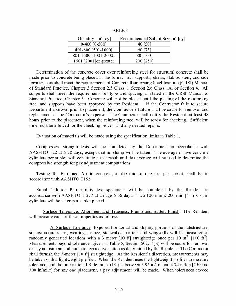
TABLE 3
Quantity m3 [cy] Recommended Sublot Size m3 [cy] 0-400 [0-500] 40 [50]
401-800 [501-1000] 60 [75] 801-1600 [1001-2000] 80 [100] 1601 [2001]or greater 200 [250]
Determination of the concrete cover over reinforcing steel for structural concrete shall be made prior to concrete being placed in the forms. Bar supports, chairs, slab bolsters, and side form spacers shall meet the requirements of Concrete Reinforcing Steel Institute (CRSI) Manual of Standard Practice, Chapter 3 Section 2.5 Class 1, Section 2.6 Class 1A, or Section 4. All supports shall meet the requirements for type and spacing as stated in the CRSI Manual of Standard Practice, Chapter 3. Concrete will not be placed until the placing of the reinforcing steel and supports have been approved by the Resident. If the Contractor fails to secure Department approval prior to placement, the Contractor’s failure shall be cause for removal and replacement at the Contractor’s expense. The Contractor shall notify the Resident, at least 48 hours prior to the placement, when the reinforcing steel will be ready for checking. Sufficient time must be allowed for the checking process and any needed repairs. Evaluation of materials will be made using the specification limits in Table 1. Compressive strength tests will be completed by the Department in accordance with AASHTO-T22 at ≥ 28 days, except that no slump will be taken. The average of two concrete cylinders per sublot will constitute a test result and this average will be used to determine the compressive strength for pay adjustment computations. Testing for Entrained Air in concrete, at the rate of one test per sublot, shall be in accordance with AASHTO T152. Rapid Chloride Permeability test specimens will be completed by the Resident in accordance with AASHTO T-277 at an age ≥ 56 days. Two 100 mm x 200 mm [4 in x 8 in] cylinders will be taken per sublot placed. Surface Tolerance, Alignment and Trueness, Plumb and Batter, Finish The Resident will measure each of these properties as follows: A. Surface Tolerance Exposed horizontal and sloping portions of the substructure, superstructure slabs, wearing surface, sidewalks, barriers and wingwalls will be measured at randomly generated locations with a 3 meter [10 ft] straightedge once per 10 m2 [100 ft2]. Measurements beyond tolerances given in Table 5, Section 502.14(E) will be cause for removal or pay adjustment and potential corrective action as determined by the Resident. The Contractor shall furnish the 3-meter [10 ft] straightedge. At the Resident’s discretion, measurements may be taken with a lightweight profiler. When the Resident uses the lightweight profiler to measure tolerance, and the International Ride Index (IRI) is between 3.95 m/km and 4.74 m/km [250 and 300 in/mile] for any one placement, a pay adjustment will be made. When tolerances exceed
5-25

4.74 m/km [300 in/mile], there will be cause for removal or a pay adjustment and potential corrective action. B. Alignment and Trueness Alignment and trueness may be measured by the Resident longitudinally along any vertical surface of any portion of the structure and shall not exceed a deviation of 5 mm per meter [¼ inch in 3 ft] for structures up to 10 meters [30 ft] in length. Structures in excess of 10 meters [30 ft] in length will be subject to a maximum tolerance of 50 mm [2 in]. Measurements exceeding these tolerances will be cause for removal or pay adjustment and potential corrective action as determined by the Resident. C. Plumb and Batter The Resident will measure all columns and other vertical surfaces that will remain exposed to determine actual batter and plumbness. Measurements will be taken subsequent to every placement. Vertical faces of columns will be measured at a minimum of two faces at right angles to each other. Other vertical surfaces will be measured once every 5 meters [15 ft] along the face of longitudinal wall. All measurements will be made on a per placement basis and will be subject to a tolerance of 6 mm per 3 meters [¼ inch in 10 ft]. Measurements between 6 mm and 12 mm per 3 meters [¼ inch and ½ inch in 10 ft] will result in pay adjustments. Measurements beyond 12 mm per 3 meters [½ inch in 10 ft] will be cause for removal or pay adjustment and potential corrective action as determined by the Resident. D. Finish The Resident will measure and determine the areas to be repaired in accordance with Sections 502.10(d), 502.13, and 502.14(e) for each placement. Areas to be repaired will be measured as a percentage of the total surface area of the placement. Those areas to be repaired that are between 0 percent and 5 percent of the total surface area of the placement will result in no pay adjustment. Areas to be repaired that are between 5 percent and 10 percent will result in pay adjustments. Areas greater than 10 percent of the total surface area of the placement will be cause for removal or pay adjustment and corrective action as determined by the Resident. Appropriate pay adjustments, as described in Section 502.194, will be made for any or all of the properties described above that do not meet specification requirements. Rejection by Resident For an individual sublot with a calculated pay factor of less than 0.80, the Department will, at its sole discretion:
A. Require the Contractor to remove and replace the entire affected placement with
concrete meeting the Contract requirements at no additional expense to the Department, or
B. Accept the material, at a reduced payment as determined by the Department. (See also Section 502.191)
For a lot in progress, the Contractor shall discontinue operations whenever one or more of the following occurs:
5-26

A. The pay factor for any property drops below 1.00 and the Contractor is taking no corrective action
B. The pay factor for any property is less than 0.90 C. The Contractor fails to follow the QC Plan 502.0503 Quality Assurance METHOD B The Department will determine the acceptability of the concrete through a quality assurance program. The Department will take verification tests at times deemed appropriate by the Resident. Verification tests will include compressive strength, air content and permeability. Surface Tolerance, Alignment and Trueness, Plumb and Batter, and Finish will be measured as described in Section 502.0502. Concrete sampling for verification tests will be taken at the discharge point, with pumped concrete sampling taken at the discharge end of the pump line. Compressive strength test will be completed by the Department in accordance with AASHTO T22 at 28 days except that no slump will be taken. The average of two cylinders will be used to determine compressive strength. Testing for entrained air in concrete, at the rate of one test per sublot, shall be in accordance with AASHTO T152. Rapid chloride permeability test specimens will be completed by the Resident in accordance with AASHTO T277 at an age > 56 days. Two 100 mm x 200 mm [4 in x 8 in] cylinders will be taken per sublot placed. Determination of the concrete cover over reinforcing steel for structural concrete shall be made prior to concrete being placed in the forms. Bar supports, chairs, slab bolsters, and side form spacers shall meet the requirements of CRSI Chapter 3, Section 2.5 Class 1, Section 2.6 Class 1A or Section 4. All supports shall meet the requirements for type and spacing as stated in the Concrete Reinforcing Steel Institute (CRSI) Manual of Standard Practice, Chapter 3. Concrete will not be placed until the placing of the reinforcing steel and supports have been approved by the Resident. If the Contractor fails to secure Department approval prior to placement, the Contractor’s failure shall be cause for removal and replacement at the Contractor’s expense. The Contractor shall notify the Resident, at least 48 hours prior to the placement, when the reinforcing steel will be ready for checking. Sufficient time must be allowed for the checking process and any needed repairs. Rejection by Resident For material represented by a verification test with a calculated pay factor of less than 0.80, the Department will, at its sole discretion:
A. Require the Contractor to remove and replace the entire affected placement with concrete meeting the Contract requirements at no additional expense to the Department, or
5-27

B. Accept the material, at a reduced payment as determined by the Department. 502.0504 Quality Assurance Method C Concrete The Department will determine the acceptability of the concrete through written verification from the Contractor that the concrete is in conformance with the Specifications. The Department reserves the right to perform verification tests at times deemed appropriate by the Resident, if the composition and proportioning of the concrete is in question. Verification tests will include compressive strength, air content and permeability. The results of verification tests may be cause for removal if it is determined that the concrete does not Substantially Conform to the Contract requirements, as determined by the Department. 502.0505 Resolution of Disputed Acceptance Test Results The Contractor shall work cooperatively with the Resident in maintaining Control Charts, as outlined in Subsection 106.4.3, in order to identify potential issues with any test results and take appropriate actions to address these issues before they become disputed issues. Circumstances may arise, however, where the Department’s test results indicate that the material has a calculated pay factor of less than 0.80. In these cases, the Department may determine that removal of the affected placement is warranted, or that the material is marginally acceptable and may remain in place and paid for at a reduced rate, in accordance with Sections 502.0502 and 502.0503 - Quality Assurance METHOD A and METHOD B. This Subsection provides recourse for the Contractor to contest the Department’s QA test results as follows, at no additional cost to the Department:
A. Compressive Strength In accordance with Section 502.191 - Pay Adjustments for Compressive Strength, the Contractor must take appropriate corrective measures when compressive strength test results are out of conformance. There may be situations where there is the possibility that an underlying structural element could be built-upon before test results for the underlying element have been reported, based upon the normal frequency of testing. In these instances, it is in the Contractor’s best interest to perform additional testing that will provide indications that the concrete will meet the requirements of the applicable Specifications, prior to continuing to build upon this underlying element. In the extreme case where an underlying structural element has been built-upon before test results for the underlying element have been reported, the above mentioned safeguards of tracking and additional testing have failed and the final test results for the concrete of the underlying element indicate that removal is warranted and the Contractor’s QC results do not confirm the Department’s test results, the following procedure concerning compressive strength may be undertaken by the Contractor and witnessed by the Department, within 36 days of the placement date.:
1. Drilled core specimens shall be retrieved from the concrete in question in accordance with the requirements of ASTM C42/C42M, Standard Test Method for Obtaining and Testing Drilled Cores and Sawed Beams of Concrete. The core strength acceptance and evaluation criteria included in ACI 318 shall not apply.
2. Three drilled core specimens shall be taken from each sublot in question, from randomly selected locations to be representative to the entire volume of the sublot. The
5-28

Resident and the Contractor’s representative shall agree on the sample locations prior to drilling. The specimens shall have a minimum diameter of 100mm [4 in] and a minimum length of 200mm [8 in].
3. The concrete cores shall be taken directly from the Project to the nearest MDOT laboratory where they will be tested. The cores shall be protected from drying during transport. The Contractor shall make arrangements with the appropriate MDOT laboratory for testing prior to beginning the coring process.
4. Core test results will be evaluated by the Department with the understanding that the strength of drilled cores is, in general, 85% of that of corresponding standard-cured molded cylinders. Therefore, the test results of the three cored cylinders shall be averaged, and then divided by a factor of 0.85. The resulting compressive strength shall be used by the Department in the final determination of the acceptability of the material in question and shall replace the contested test result in computing pay adjustments for the sublot in question. If coring is not done with the 36-day time limit the Department will not allow dispute testing of the sublot.
5. If the Department concludes that the strength of the structural element in question is adequate as a result of the above procedure, then the concrete shall remain in place and will be paid for at a reduced rate, as determined by the Department. If the Department concludes that the strength of the structural element in question is unsatisfactory as a result of the above procedure, then the Department will direct the Contractor to take appropriate actions, as determined by the Department, and at no additional cost to the Department.
In the case where the Department’s test results for compressive strength for a particular sublot indicate that the material has a pay factor of less than 1.00 and the Department determines that the indicated strength is adequate for the structural element in question, but the Contractor’s QC results indicate a significantly higher strength than the Department’s results, the Contractor may contest the Department’s results, provided the laboratory performing the QC testing is certified by NETTCP. When the Contractor’s QC results for a particular sublot are higher than the Department’s results by more than 3.45 MPa [500 psi], the Contractor may elect to undertake the preceding five-step procedure.
B. Rapid Chloride Permeability The Department’s verification testing may result in values that exceed the maximum permeability requirements outlined in Section 502.192 - Pay Adjustment for Chloride Permeability, for a particular sublot. In this situation, where the material is subject to rejection and replacement, the following procedure concerning permeability maybe undertaken by the Contractor, if initiated within four calendar days of the receipt of the results and witnessed by the Department:
1. Drilled core specimens shall be retrieved from the concrete in question in accordance with the requirements of ASTM C42/C42M, Standard Test Method for Obtaining and Testing Drilled Cores and Sawed Beams of Concrete. Specimens shall have a diameter of 200mm [8 in] and a minimum length of 400mm [16 in].
5-29

2. One drilled core specimen shall be taken from a location that would be from the same load as the original Department specimen for each sublot in question.
3. The concrete cores shall be taken directly from the Project to the nearest MDOT laboratory where they will be tested. The cores shall be protected from drying during transport. The Contractor shall make arrangements with the appropriate MDOT laboratory for testing prior to beginning the coring process.
4. The cored cylinder will be tested by the Department in accordance with AASHTO T-277. The resulting permeability value shall be used by the Department in the final determination of the acceptability of the material in question and shall replace the contested test result in computing pay adjustments for the sublot in question.
5. If the Department concludes that the permeability of the placement in question is
adequate as a result of the above procedure, then the concrete shall remain in place and will be paid for at a reduced rate, as determined by the Department. If the Department concludes that the permeability of the affected placement in question is unsatisfactory as a result of the above procedure, then the Department will direct the Contractor to take appropriate actions, as determined by the Department, and at no additional cost to the Department.
Because the Contractor does not perform permeability testing, the Contractor may not
contest the Department’s results in a situation where the Department’s results are within acceptable limits
C. Entrained Air In order to dispute the Department’s test results, the Contractor must
test material from the same sample as the Department. If the difference between the Department’s and the Contractor’s air tests is equal to or greater than 0.8 percent, then the material shall be retested by both parties. If the difference between the retests is equal to or greater than 0.8 percent, the concrete placement will be suspended immediately, and 1) both air meters shall be calibrated immediately, or 2) the Contractor shall immediately replace both air meters. Once it is demonstrated the QC and Acceptance air meters are in agreement with 0.8 percent, the concrete placement may resume.
502.06 Batching Measuring and batching of materials for Method A and Method B shall be performed at an approved batching plant, either commercial or otherwise in accordance with the QC Plan. Measuring and batching of materials for Method C concrete shall be performed at an approved batching plant. The plant shall meet the requirements of AASHTO M-157. 502.0701 Delivery A. Delivery and discharge of the concrete from the mixer shall be completed within a maximum of 1½ hours from the time the cement is added to the aggregate, except that in hot weather when the concrete mix temperature exceeds 21°C [70°F] or under other conditions contributing to quick stiffening of the concrete, delivery and discharge from the mixer shall be
5-30
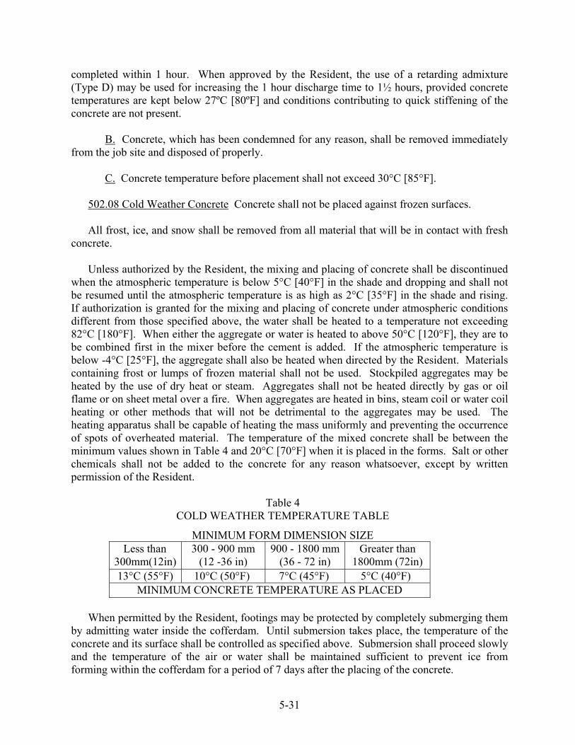
completed within 1 hour. When approved by the Resident, the use of a retarding admixture (Type D) may be used for increasing the 1 hour discharge time to 1½ hours, provided concrete temperatures are kept below 27ºC [80ºF] and conditions contributing to quick stiffening of the concrete are not present. B. Concrete, which has been condemned for any reason, shall be removed immediately from the job site and disposed of properly. C. Concrete temperature before placement shall not exceed 30°C [85°F].
502.08 Cold Weather Concrete Concrete shall not be placed against frozen surfaces. All frost, ice, and snow shall be removed from all material that will be in contact with fresh concrete. Unless authorized by the Resident, the mixing and placing of concrete shall be discontinued when the atmospheric temperature is below 5°C [40°F] in the shade and dropping and shall not be resumed until the atmospheric temperature is as high as 2°C [35°F] in the shade and rising. If authorization is granted for the mixing and placing of concrete under atmospheric conditions different from those specified above, the water shall be heated to a temperature not exceeding 82°C [180°F]. When either the aggregate or water is heated to above 50°C [120°F], they are to be combined first in the mixer before the cement is added. If the atmospheric temperature is below -4°C [25°F], the aggregate shall also be heated when directed by the Resident. Materials containing frost or lumps of frozen material shall not be used. Stockpiled aggregates may be heated by the use of dry heat or steam. Aggregates shall not be heated directly by gas or oil flame or on sheet metal over a fire. When aggregates are heated in bins, steam coil or water coil heating or other methods that will not be detrimental to the aggregates may be used. The heating apparatus shall be capable of heating the mass uniformly and preventing the occurrence of spots of overheated material. The temperature of the mixed concrete shall be between the minimum values shown in Table 4 and 20°C [70°F] when it is placed in the forms. Salt or other chemicals shall not be added to the concrete for any reason whatsoever, except by written permission of the Resident.
Table 4 COLD WEATHER TEMPERATURE TABLE
MINIMUM FORM DIMENSION SIZE Less than
300mm(12in) 300 - 900 mm
(12 -36 in) 900 - 1800 mm
(36 - 72 in) Greater than
1800mm (72in) 13°C (55°F) 10°C (50°F) 7°C (45°F) 5°C (40°F)
MINIMUM CONCRETE TEMPERATURE AS PLACED When permitted by the Resident, footings may be protected by completely submerging them by admitting water inside the cofferdam. Until submersion takes place, the temperature of the concrete and its surface shall be controlled as specified above. Submersion shall proceed slowly and the temperature of the air or water shall be maintained sufficient to prevent ice from forming within the cofferdam for a period of 7 days after the placing of the concrete.
5-31
When depositing concrete under water, there shall be no ice inside the cofferdam. Permission given to place concrete under the conditions mentioned above and as described in the Contractor's QC Plan shall not relieve the Contractor of responsibility for obtaining satisfactory results. The Contractor shall be wholly responsible for the protection of concrete during cold weather operations and any concrete injured by frost action or overheating shall be removed and replaced at the Contractor's expense. 502.10 Forms and False work A. Construction of Forms All forms shall be well built, substantial and unyielding, securely braced, strutted and tied to prevent motion and distortion while concrete is being placed in them. The forms shall be strong enough to safely support the weight of the concrete and all superimposed loads (such as runways, concrete buggy loads, workers, scaffolding, etc.) placed upon them. Forms shall be built to conform to the dimensions, location, contours and details shown on the Plans. The faces of forms against which the concrete is to be placed shall be dressed smooth and uniform and shall be free from winds, twists, buckles and other irregularities. Stay-in-place forms of any type will not be permitted for any part of the slab structures, unless otherwise indicated on the Plans. The placing of concrete in excavated pits and trenches without forms will be permitted only in exceptional cases and then at the discretion of the Resident. All corners within the forms shall be fitted with chamfer strips mitered at their intersections, except that chamfer strips will not be required as follows: (1) on corners of slab blocking of interior steel beams and the inside of exterior steel beams; (2) on corners constructed transversely at the underside of the slab of superstructures which consist of a concrete slab on steel beams; (3) on footings not exposed to view; and (4) on all structures when more than 600 mm [2 ft] below the final finished ground line. Chamfer strips shall have a width across the diagonal face between 15 and 20 mm [½ and ¾ in]. The size to be adopted for a given portion of the work shall depend upon the general dimensions. Except where special size chamfer strips are shown on the Plans, the size of chamfer strips shall be uniform on individual projects. Provision shall be made for the chamfering of the top edges of abutment bridge seats and wing walls, tops of piers and retaining walls, tops of through girders, roadway curbs, etc., by nailing chamfer strips inside the forms. Unless otherwise provided, all chamfer strips shall produce plain flat surfaces on the concrete. The forms for beams, girders and spandrel arches shall be so constructed as to permit the sides to be removed without disturbing the supports. All foreign matter within the forms shall be removed before depositing concrete in them.
5-32
In all cases where metal anchorages or ties within or through the face forms are required to hold the forms in their correct position, such anchorages or ties shall be of ample strength and shall be so constructed that the metal work can be removed to a depth of not less than 25 mm [1 in] from the face and back surfaces of the concrete without damaging such surfaces. Elevations will be taken on the top flanges of structural steel beams and girders for the purpose of determining the depth of blocking necessary for the construction of the forms for the concrete slab, after the following conditions have been satisfied:
1. The satisfactory erection of the superstructure structural steel beams or girders, including any required flooring beams and stringers, unless an alternative plan is submitted by the Contractor and approved by the Department. 2. All bolt tightening operations must be complete. 3. No foreign loads supported by the beams or girders are present.
The Contractor shall submit working drawings for approval of the proposed forms and false work supporting the overhanging portion of the superstructure slab in accordance with Section 105.7. The working drawings shall show the size and location of the supporting members, the proposed loads and the weight of concrete forms to be carried by the members.
In the construction of forms and false work for the portion of superstructure slabs overhanging the exterior members of beam and girder spans, forms and supporting devices resulting in point loadings on the exterior members shall not be used. Loads resulting from supporting devices shall be distributed directly to the flanges by means of brackets or braces. All forms shall be inspected and approved by the Department before the placing of any concrete within them. B. Surface Treatment of Forms The inside surfaces of forms shall be uniformly coated with form oil or other approved surface treatment. Form surfaces shall be treated before placing the reinforcing steel. C. Construction of False work All false work used for supporting reinforced concrete superstructures shall be composed of members having ample structural sections to resist all loads imposed upon them, with deformations less than span length / 360.
When the vertical members of false work consist of piles or when framed or other false work is supported upon piles, the piles shall be driven to secure a safe load resistance. When false work is supported upon mud sills, the foundation pressures resulting from the imposed loads upon the mud sills (false work, forms, fresh concrete, scaffolding, etc.) shall not exceed the capacity of the on-site soils.
5-33

All false work systems shall be designed to support all vertical loading and any differential settlement forces, all horizontal and longitudinal forces, and shall account for any temporary unbalanced loading due to the placement sequence of the concrete. Sufficient redundancy shall be designed into centering or false work systems so that the failure of any member shall not cause a collapse. Design computations, layout drawings, and details of materials for the centering or false work systems shall be submitted to the Department for its records. The erection of centering or false work systems shall be accomplished in strict conformance with the design and details. No concrete shall be placed without prior approval of the Resident. False work systems adjacent to and/or over traveled ways shall additionally be designed to resist any vibration forces due to traffic and shall incorporate sufficient protection against impact by errant vehicles. All false work system computations, plans, and working drawings shall be designed and sealed by the Contractor’s Professional Engineer, who must be registered in the State of Maine. This Professional Engineer may be directly employed, or otherwise retained, by the Contractor. Prior to concrete placement, the Professional Engineer responsible for the design of the false work system shall, after false work inspection, provide a sealed certification to the Resident that the system was erected in conformance with the Professional Engineer’s plans and design details. False work shall be so constructed that the forms will have a camber, the amount depending upon the deflection anticipated in the design. Forms supported upon false work shall be provided with a satisfactory means for their adjustment in the event of settlement or deformation of the false work due to overloading or other causes. Provisions shall be made for the gradual lowering of false work and rendering the supported structure self-supporting. D. Removal of Forms and False work 1. Location, weather conditions, cementitious materials used and the character of the structure involved shall be considered in determining the time for the removal of forms. Forms shall not be removed until concrete cylinders cured with the structure establish that the concrete has developed 80 percent of design strength. The Contractor shall cast and break two cylinders per sublot and furnish the Resident with these test reports before removal of the forms. When approved by the Resident, the vertical forms of footings, walls, columns and sides of beams and slabs may be removed 48 hours after completion of placement of concrete, exclusive of the time the ambient air temperature is below 7°C [45°F] and provided the following conditions are met:
5-34
Immediately after the forms are removed, defects in the concrete surface shall be repaired in accordance with Section 502.13 and the repaired area thoroughly dampened with water. The surfaces of exposed concrete shall be cured for the remainder of the 7-day curing period by the application of a product listed on the Maine Department of Transportation Prequalified list of curing compounds. The curing compound shall be applied continuously by an approved pressure spraying or distributing equipment at a rate necessary to obtain an even, continuous membrane, meeting the manufacturer’s recommendation but at a rate of not less than 0.2 L/m² [1 gal/200 ft²] of surface. Other methods of curing concrete may be used with the prior approval of the Resident. 2. Forms and false work, including blocks and bracing, shall not be removed without the consent of the Resident. The Resident's consent shall not relieve the Contractor of responsibility for the safety of the work. In no case shall any portion of the wood forms be left in the concrete. As the forms are removed, all projecting metal devices that have been used for holding the forms in place shall be removed in accordance with Section 502.10. The holes shall be filled as required in Section 502.13. 502.11 Placing Concrete A. General Concrete shall not be placed until forms and reinforcing steel have been checked and approved by the Resident. The forms shall be clean of all debris. The method and sequence of placing the concrete shall be approved before any concrete is placed. All concrete shall be placed before it has taken its initial set and, in any case, as specified in Section 502.0701. Concrete shall be placed in horizontal layers in such a manner as to avoid separation and segregation. A sufficient number of workers for the proper handling, tamping and operation of vibrators shall be provided to compact each layer before the succeeding layer is placed and to prevent the formation of cold joints between layers. Care shall be taken to prevent mortar from spattering on structural steel, reinforcing steel and forms. Any concrete or mortar that becomes dried on the structural steel, reinforcing steel or forms shall be thoroughly cleaned off before the final covering with concrete. Following the placing of the concrete, all exposed surfaces shall be thoroughly cleaned as required, with care not to injure any surfaces. Concrete shall not come in direct contact with seawater during placing and for a period of 72 hours thereafter, except as follows:
1. Concrete seals that are located entirely below low tide. 2. Concrete footings constructed in the dry and located entirely below low tide or final ground elevation. 3. Concrete Fill placed under water.
Concrete in any section of a structure shall be placed in approximately horizontal layers of such thickness that the entire surface shall be covered by a succeeding layer before the underlying layer has taken its initial set. Layers shall not exceed 450 mm [18 in] in thickness
5-35

and be compacted to become an integral part of the layer below. Should the placement be unavoidably delayed long enough to allow the underlying layer to take initial set or produce a so-called "cold joint", the following steps shall be taken: An incomplete horizontal layer shall be bulk-headed off to produce a vertical joint. Horizontal joints shall be treated as required in this Section 502.11(f). Portland cement concrete with a high range, water reducing admixture shall not be placed when the concrete mix temperature is below 5°C [40°F] or above 29°C [85°F]. The concrete in superstructures shall be placed monolithically except when construction joints are shown on the Plans or are authorized in accordance with approved details submitted by the Contractor. If the concrete in the stems of T-beams is to be placed independent of the slab section, the construction joint shall be located at the under side of the slab and the bond between stem and slab shall be a mechanical one. The bond shall be produced by embedding 38 by 89 mm [2 by 4 in] wooden blocks having a length approximately 100 mm [4 in] less than the width of the stem and placed horizontally at right angles to the centerline of the beam in the top surface of the concrete immediately following the completion of the concrete placement. To provide for the uniform spacing of the blocks and their ready removal when the concrete has taken a set sufficient to hold its form, the blocks shall be firmly nailed upon a board at a distance of 300 mm [1 ft] center to center. The blocks shall be thoroughly oiled to facilitate their ready removal from the concrete. In arch spans, the order of construction or sequence of the work, as shown on the Plans, shall be followed in the placing of concrete. In no case shall the work on any section or layer be stopped or temporarily discontinued within 450 mm [18 in] below the top of any face, unless the Plans provide for a coping having a thickness less than 450 mm [18 in], in which case at the option of the Resident, the construction joint may be made at the under side of the coping. Concrete in columns shall be placed in one continuous operation, unless otherwise directed. Fresh concrete, threatened with rain damage shall be protected by approved means. Sufficient material for covering the work expected to be done in one day shall be on hand at all times for emergency use. The covering shall be supported above the surface of the concrete. Concrete Fill shall be placed at least to the pay limits shown on the Plans. Forms may be omitted at the Contractor’s option. Vibration of concrete will not be required. The Contractor has the option of placing Concrete Fill under water or in the dry. B. Chutes, Troughs, Pipes and Buckets Sectional drop chutes or short chutes, troughs, pipes and buckets when used as aids in placing concrete, shall be arranged and used in such a manner that the ingredients of the concrete do not become separated or segregated. Wood and aluminum chutes, troughs, pipes or buckets shall not be used.
5-36
Dropping the concrete a distance of more than 2 m [6 ft], unless confined by closed chutes or pipe will not be permitted. The concrete shall be deposited at or as near as possible to its final position. C. Vibrating Mechanical, high frequency internal vibrators shall be used, operating within the concrete, for compacting the concrete in all structures and precast and cast-in-place piles, with the exception of concrete placed under water. The vibrators shall be an approved type, with a frequency of 5,000 to 10,000 cycles per minute and shall be visibly capable of properly consolidating the designed mixture. A spare vibrator shall be available on the project at all times during the placing of concrete. Sufficient vibrators shall be used to consolidate the incoming concrete within 5 minutes after placing. Vibrators shall neither be held against forms or reinforcing steel, nor shall they be used for flowing the concrete or spreading it into place. Over-vibrating shall not be allowed. D. Dewatering Forms All forms shall be dewatered before concrete is placed in them. Pumping will not be permitted from the inside of forms while concrete is being placed. Moving water shall not be permitted to be exposed to fresh concrete. E. Depositing Concrete under Water No concrete shall be deposited under water except for cofferdam seals. Pumping will not be allowed within the cofferdam while concrete is being placed. The concrete shall be placed carefully in a compact mass in its final position by means of a tremie or by other approved means and shall not be disturbed after being deposited. Bottom dump buckets will not be permitted. Special care must be exercised to maintain still water at the point of deposit. Concrete shall not be placed in running water. The method of depositing concrete shall be so regulated as to produce approximate horizontal surfaces. Each seal shall be placed in one continuous operation. When a tremie is used, it shall consist of a tube not less than 250 mm [10 in] in diameter. The means of supporting the tremie shall be such as to permit free movement of the discharge end over the entire seal and to permit its being lowered rapidly, when necessary to choke off or retard flow. The tremie shall be filled by a method that will prevent washing of the concrete. The discharge end shall be completely submerged in concrete at all times and the tremie tube shall be kept full to the bottom of the hopper. The flow shall be regulated by raising or lowering the tremie. When the horizontal area of the tremie seal is large, several tremie hoppers shall be provided and positioned strategically to allow easy deposit of concrete near the point where it is needed to avoid moving concrete horizontally through the water. The number of tremie hoppers and the work plan shall be approved by the Resident. All laitance or other unsatisfactory material shall be removed from the surface of the seal before placing additional concrete. The surface shall be cleaned by scraping, chipping or other means that will not injure the concrete.
5-37

The placing and dewatering of seal concrete within cofferdams shall be in accordance with Section 511 - Cofferdams. F. Construction Joints Construction joints shall be located where shown on the Plans or permitted by the Resident. When the concrete is in seawater, except concrete cores for stone masonry, no horizontal construction joint will be permitted between extreme low tide and extreme high tide elevations. At horizontal construction joints, temporary gage strips having a minimum thickness of 38 mm [1 ½ in] shall be placed horizontally inside the forms along all exposed faces to give the joints straight lines. The joint shall be so constructed that the surface of the concrete will not be less than 6 mm [¼ in] above the bottom of the gage strip. Before placing fresh concrete, the temporary gage strip shall be removed, the surfaces of construction joints shall be thoroughly cleaned, drenched with water until saturated and kept saturated until the new concrete is placed. Immediately prior to placing new concrete, the forms shall be drawn tight against the concrete already in place. Concrete in substructures shall be placed in such a manner that all horizontal joints will be horizontal and if possible, in locations such that they will not be exposed to view in the finished structure. Where vertical construction joints are necessary, reinforcing bars shall extend across the joint in such a manner as to make the structure monolithic. Construction joints through paneled wing walls or other large surfaces which are to be treated architecturally will not be allowed except as shown on the Plans. All vertical construction joints in abutments and retaining walls shall contain water stops as shown on the Plans. The water stops shall be one continuous piece at each location. All horizontal construction joints in abutments and retaining walls shall be constructed using a joint cover, as shown on the Plans. Construction joints in the wearing surface shall be located where called for on the Plans. No other construction joints will be allowed. All joints shall be formed in the manner detailed on the Plans. The forms shall not be treated with oil or any other bond breaking material that will adhere to the concrete. Sealing slots shall be provided at all joints in the wearing surface that are located directly over a slab construction joint. Construction joints in the wearing surface not receiving a sealing slot shall be brushed with a neat cement paste immediately prior to making the adjacent concrete placement. After the concrete has been cured, sealing slots, when required, shall be sandblasted with approved equipment to remove all laitance and foreign material on the surfaces of the slots. The bottom of the sealing slots shall receive an approved bond breaker. The joint shall then be filled within 3 mm [⅛ in] of the surface with a poured sealant conforming to the following requirements and in accordance with the manufacturer's recommendations. The joint sealant
5-38
supplied shall be an approved two component, elastomeric sealant capable of 50 percent joint movement. Both components shall be in liquid form and the combining ratio of components by volume shall be as recommended by the manufacturer. G. Concrete Wearing Surface and Structural Concrete Slabs on Precast Superstructures When called for on the Plans, a separate concrete wearing surface or structural concrete slabs on precast superstructures shall be bonded to the supporting slab. No surface preparation of a new structural concrete slab shall begin before completion of the specified curing period. When the supporting slab is composed of cast-in-place concrete the Contractor shall scabble the entire surface of the structural concrete slab and then sandblast the entire structural concrete slab surface. When the supporting slab is comprised of precast units, the Contractor shall sandblast the entire deck surface. The entire area of the deck surface and the faces of curb and barrier walls or other median devices, up to a height of 25 mm [1 in] above the top elevation of the wearing surface or slab, shall be cleaned to a bright, clean appearance which is free from curing compound, laitance, dust, dirt, oil, grease, bituminous material, paint and all other foreign matter. Air lines shall be equipped with effective oil traps. The cleaning of an area of the deck shall be performed within the 24-hour period preceding placement of the wearing surface. The cleaning shall be performed by dry sand blasting or other methods approved by the Resident. All debris from the cleaning operation shall be thoroughly removed by compressed dry air from the cleaned surfaces and adjacent areas. The cleaned areas shall be protected against contamination before placement of the wearing surface. Contaminated areas shall be recleaned by dry sand blasting. Prepared areas that have not received the wearing surface within 36 hours shall be recleaned. All horizontal surfaces in contact with the wearing surface shall receive a coating of bonding grout or bonding agent listed on Maine Department of Transportation Prequalified List of Bonding Agents. The vertical faces in contact with the wearing surface shall be broomed up to the elevation of the top of the wearing surface with bonding grout or an approved bonding agent. Stiff bristled street brooms shall be used to brush the grout onto the surface. The coating shall not exceed 3 mm [⅛ in] in thickness. The rate of progress in applying grout shall be limited so that the grout does not become dry before it is covered with new concrete. During delays in the surfacing operations, should the surface of the grout indicate an extensive amount of drying, the grout shall be removed by methods approved by the Resident and the area should be regrouted. The bonding grout shall have Portland cement and fine aggregate proportioned 2 to 1 by volume. The fine aggregate from which the material larger than 3 mm [⅛ in] has been removed shall be the same source as used in the concrete. The cement and fine aggregate shall be measured separately in appropriately sized containers. The fine aggregate shall be deposited in an approved mechanical mortar mixer before adding cement. Water shall be added in sufficient quantity to allow flow of the grout without segregation of the grout ingredients.
5-39

No water shall be added after initial mixing. The grout shall not be allowed to separate before placement. The cement to water contact time of the grout shall not exceed 30 minutes before it is placed. Any grout that has dried or become unworkable before application, as determined by the Resident, shall not be incorporated into the work. The use of retarding admixtures for increasing the discharge time limits will be allowed. The Resident may approve the batching of bonding grout at an approved commercial concrete batch plant. In this case, mixing and delivery shall be in transit truck mixers. The boding agent shall be one of the products listed on the Maine Department of Transportation's list of Prequalified Bonding Agents and shall be applied in accordance with the manufacturer's recommendations.
No structural concrete slab structure, including but not limited to concrete deck slabs, wearing surfaces, simple slab spans, and slabs on precast superstructures, shall be commenced if the combination of ambient air temperature, relative humidity, wind speed, and plastic concrete temperature result in a surface moisture evaporation rate theoretically equal to or greater than 0.5 kg/m²/hr [0.1 lb/ft²/hr] of exposed surface (Refer to the Rate of Evaporation from Concrete Surface Chart). If the surface moisture evaporation rate rises to 0.75 kg/m²/hr [0.15 lb/ft²/hr] of exposed surface, the Contractor shall implement the remedial action described in the approved QC Plan. The temperature of the concrete shall not exceed 24°C [75°F] at the time of placement. The maximum temperature of the surface on which concrete will be placed shall be 32°C [90°F]. The Contractor shall provide all equipment and perform all measurements and calculations in the presence of the Resident to determine the rate of evaporation. Rate of Evaporation from Concrete Surface Chart
METRIC UNITS & US CUSTOMARY UNITS
Concrete Temperature 100°F (38C)90 (32C)80 (27C)70 (21C)
60 (16C)40 (4C)
50 (10C)
(40k
m/h
r)
(32km/hr)
(24km/hr)
(16km/hr)
(8km /hr)
(3km /hr)
4 .0
3.0
2.0
1.0
kg/m
2/ hr3 .0
5 15 25 35deg C
To use th is chart (English units)
1.E nter w ith the air tem perature, m ove up to the relative hum idity line.2. M ove right to the concrete tem perature.3. M ove down to the w ind veloc ity.4. M ove lef t; read rate of evaporation.
To use this chart (M etric units )
1.Enter w ith the air tem perature, m ove down to the relative hum idity line.2. M ove right to the concrete tem perature.3. M ove down to the w ind veloc ity.4. M ove right; read rate of evaporation.
5-40
502.12 Expansion and Contraction Joints Expansion and contraction joints shall be located and constructed as shown on the Plans. Water stops shall be one continuous piece at each location. Joint cover, as shown on the Plans, shall be applied to all joints where water stops cannot physically be installed, as determined by the Resident. 502.13 Repairing Defects and Filling Form Tie Holes in Concrete Surfaces After the forms are removed, all surface defects and holes left by the form ties shall be repaired. All fins and irregular projections shall be removed from the following: Surfaces which are visible in the completed work; surfaces to be waterproofed; and the portion of vertical surfaces of substructure units which is below the final ground surface to a depth of 300 mm [12 in], not including underwater surfaces. In patching surface defects, all coarse or fractured material shall be chipped away until a dense uniform surface, exposing solid coarse aggregate is obtained. Feathered edges shall be saw cut away to form faces having a minimum depth of 25 mm [1 in] perpendicular to the surface. All surfaces of the cavity shall be saturated thoroughly with water, after which a thin layer of neat cement paste shall be applied. The cavity shall then be filled with thick, reasonably stiff mortar, not more than 30 minutes old, composed of material of the same type and quality and of the same proportions as that used in the concrete being repaired. The surface of this mortar shall be floated before initial set takes place and shall be neat in appearance. The patch shall be water cured for a period of five days. If the removal of defective concrete materially impairs the soundness or strength of the structure, as determined by the Resident, the affected unit shall be removed and replaced by the Contractor at their expense. The holes left by form ties, on the portions of substructure concrete that are to be permanently covered in the finished work, may be filled with an acceptable grade of plastic roofing cement. Holes in the bottom of slabs caused by supporting hangers need not be filled. 502.14 Finishing Concrete Surfaces Neat cement paste, dry cement powder or the use of mortar for topping or plastering of concrete surfaces will not be permitted. A. Float Finish A float finish for horizontal surfaces shall be achieved by placing an excess of concrete in the form and removing or striking off the excess with a template or screed, forcing the coarse aggregate below the surface. Creation of concave surfaces shall be avoided. After the concrete has been struck off, the surface shall be thoroughly floated to the finished grade with a suitable floating tool. Aluminum and steel floats are not allowed. Float finish, unless otherwise required, shall be given to all horizontal surfaces except those intended to carry vehicular traffic and those of curbs and sidewalks. B. Structural Concrete Slab Structures Include but not limited to structural concrete deck slabs, wearing surfaces, slabs on precast superstructures, top and bottom slabs of box culverts, approach slabs, rigid frame structures and simple slab spans, as applicable. Screed
5-41

rails shall be set entirely above the finished surface of the concrete and shall be supported in a manner approved by the Resident. Where shear connector studs are available, welding to the studs will be permitted. No welding will be permitted directly on the stringer flanges to attach either screed rail supports or form supports of any type. Screed rail supports set in the concrete shall be so designed that they may be removed to at least 50 mm [2 in] below the surface of the concrete. Voids created by removal of the upper part of the screed rail supports shall be filled with mortar having the same proportions of sand and cement as that of the slab or wearing surface. The mortar shall contain an approved additive in sufficient proportions to produce non-shrink or slightly expansive characteristics. The rate of placing concrete shall be limited to that which can be finished without undue delay and shall not be placed more than 3 m [10 ft] ahead of strike-off. The Contractor shall furnish a minimum of two work bridges behind the finishing operation, capable of spanning the entire width of the deck and supporting at least a 225 kg [500 lb] load without deflection to the concrete surface, to be supported on the screed rails. These working bridges shall be used by the Contractor for touch-up and curing cover application and shall be available for inspection purposes. When the overall length of the structure is 18 m [60 ft] or less only one working bridge will be required. An approved bridge deck finishing machine complying with the following requirements shall be used, except as otherwise specified, for finishing structural concrete slab structures. The finishing machine shall have the necessary adjustments, built in by the manufacturer, to produce the required cross section, line and grade. The supporting frame shall span the section being cast in a transverse direction without intermediate support. The finishing machine shall be self-propelled and capable of forward and reverse movement under positive control. Provisions shall be made for raising all screeds to clear the screeded surface for traveling in reverse. The screed device shall be provided with positive control of the vertical position. The finishing machine shall be self-propelled with one or more oscillating screeds or one or more rotating cylinder screeds. An oscillating screed shall oscillate in a direction parallel to the centerline of the structure and travel in a transverse direction. A rotating cylinder screed shall rotate in a transverse direction while also traveling in the same direction. Either type of screed shall be operated transversely in overlapping strips in the longitudinal direction not to exceed 150 mm [6 in]. One or more powered augers shall be operated in advance of the screed(s) and a drag (pan type) float shall follow the screed(s). For concrete placements less than 150 mm [6 in] in depth, vibratory pan(s) having a minimum of 3000 vibrations/min shall be operated between the oscillating screed(s) or rotating cylinder screed(s) and the power auger(s). For concrete placed in excess of 90 mm [3 ½ in] but less than 150 mm [6 in] thickness, hand-operated spud vibrators shall be used in addition to the machine vibratory pan(s). The transversely operated rotating cylinder(s) of the bridge deck finishing machine shall be rotated such that the direction of the rotation of the cylinder(s) at the surface of the concrete is in accordance with the manufacturer's recommendations.
5-42
Concrete immediately in front of the power auger(s) of a bridge deck finishing machine shall be placed or cut to a depth no higher than the center of the rotating auger(s). The advance auger(s) shall strike off the concrete to approximately 6 mm [¼ in] above the final grade. The concrete shall then be consolidated with the vibrating pan(s) and then finished to final grade. A small handheld pan vibrator shall be required at edges and adjacent to joint bulkheads. In lieu of the handheld pan vibrator equipment, the Resident may approve small spud vibrator(s). Lightweight, vibrating screeds may be used on slab structures which are more than 300 mm [12 in] below the roadway finish grade or have a length of 9 m [30 ft] or less, or where concrete placements are specified to be less than 5 m [16 ft] in width and shall have the following features:
1. It shall be portable and easily moved, relocated, or adjusted by no more than four persons. 2. The power unit shall be operable without disturbing the screeded concrete. 3. It shall be self-propelled with controls that will allow a uniform rate of travel and by which the rate of travel can be increased, decreased or stopped. 4. It shall have controlled, uniform, variable frequency vibration, end to end. 5. It shall be fully adjustable for flats, crowns, or valleys. 6. The screed length shall be adjustable to accommodate the available work area.
When a lightweight vibrating screed is utilized, the concrete shall be placed or cut to no more than 13 mm [½ in] above the finished grade in front of the front screed. The screed shall be operated such that at least 1 m [3 ft] of concrete is in position in front of the screed. Supporting slabs for bituminous wearing surfaces shall be finished in accordance with the recommendations of the waterproofing membrane manufacturer. The texturing of concrete wearing surfaces shall be applied as approved by the Resident. The surface tolerance and texture shall be acceptable to the Resident, or the placement may be suspended until remedial action has been taken. The Resident may order the removal and replacement of material damaged by rainfall. On all concrete wearing surfaces, a 300 mm [1 ft] wide margin shall be finished adjacent to curbs and permanent barriers with a magnesium float. Immediately after screeding, floating and texturing, the surface of the concrete shall be tested for trueness, by the Contractor, with a 3 m [10 ft] straightedge and all irregularities corrected at once in order to provide a final surface within the tolerance required in Table 5. The surface shall be checked both transversely and longitudinally. Any area that requires finishing to correct surface irregularities shall be retextured.
5-43

The straightedges shall be furnished and maintained by the Contractor. They shall be fitted with a handle and all parts shall be made of aluminum or other lightweight metal. The straightedges shall be made available for use by the Resident when requested. In the event of a delay during a concrete placement, all concrete that cannot receive the final curing cover shall be covered with wet burlap. No vehicles will be allowed, either directly or indirectly, on reinforcing steel before concrete placement. C. Curb and Sidewalk Finish on Bridges Curb and sidewalk finish is a float finish produced by using a short float, moved in small circles to produce a shell-like pattern on the surface of the concrete. Alternately, sidewalks may receive a light broom finish perpendicular to the sidewalk. When a concrete curb is monolithic with a sidewalk, a 150 mm [6 in] wide smooth margin shall be made along the top of the curb with a magnesium float. Unless shown on the Plans, the sidewalk area shall not be divided into sections by transverse grooves. At all transverse construction and expansion joints, except where steel expansion dams are used, the edges of the joints, on the surface of the sidewalk, shall be finished with a sidewalk edging tool, 50 mm [2 in] in width, with a 6 mm [¼ in] radius lip. D. Form Surface Finish The character of the materials used and the care with which forms are constructed and concrete placed shall be considered in determining the amount of rubbing required. If, using first class form material, well-constructed forms and the exercise of special care, concrete surfaces are obtained that are satisfactory to the Resident, the Contractor may be relieved in part from the requirement of rubbing. 1. Ordinary Finish An Ordinary Finish is defined as the finish left on a surface after the removal of the forms, the filling of all holes and the repairing of all defects. The surface shall be true and even, free from stone pockets and depressions or projections and of uniform texture. All formed concrete surfaces shall be given an ordinary finish unless otherwise specified. Repaired areas that do not meet the above requirements or areas that cannot be satisfactorily repaired to meet the requirements for ordinary finish shall be given a rubbed finish. When a rubbed finish is required on any part of a surface, the entire surface shall be given a rubbed finish. 2. Rubbed Finish After removal of forms, the rubbing of concrete shall be started as soon as its condition will permit. Immediately before starting this work, the concrete shall be thoroughly saturated with water. Sufficient time shall have elapsed before wetting down to allow the mortar used in ordinary finish to become thoroughly set. Surfaces to be finished shall
5-44
be rubbed with a medium coarse carborundum stone, using a small amount of mortar on its face. The mortar shall be composed of cement and fine sand mixed in proportions as used in the concrete being finished. Rubbing shall be continued until all form marks, projections and irregularities have been removed, all voids filled and a uniform surface has been obtained. A thin layer of paste produced by this rubbing shall be left on the surfaces. After all concrete above the surface being treated has been cast, the final finish shall be obtained by a second rubbing with a fine carborundum stone using only water. This rubbing shall be continued until the entire surface is of a smooth texture and uniform color. The paste produced by this second rubbing shall be carefully spread with a moist whitewash brush to form a very thin uniform coating upon the surface of the concrete. After the final rubbing is completed and the surface has dried, it shall be rubbed lightly with clean and dry burlap to remove excess loose powder and shall be left free from all unsound patches, paste, powder and objectionable marks. This finish shall result in a surface of smooth texture and uniform color. No surface finishing shall be done in freezing weather or when the concrete contains frost. In cold weather the preliminary rubbing necessary to remove the inert sand and cement materials and the surface irregularities may be done without the application of water to the concrete surfaces. The following portions of concrete roadway grade separation structures shall be given a rubbed finish unless otherwise indicated in the Contract:
(a) Retaining walls and the breast and wing walls of abutments-face surfaces to 300 mm [12 in] below the finished ground line.
(b) Piers-All vertical surfaces and the underside of overhanging portions of caps,
except that for overpass structures, the piers beyond the outside limits of the roadway pavement, the vertical surfaces on the back which are not visible from the roadway or sidewalk will not require a rubbed finish.
If, in the opinion of the Resident, the general appearance of a concrete structure, due to the excellence of workmanship, cannot be improved by a rubbed finish, this requirement may be waived.
E. Surface Finish After the concrete has cured the surface shall be tested with a 3m [10 ft] straightedge or a lightweight profiler. The straightedge shall be furnished and maintained by the Contractor. It shall be fitted with a handle and all parts shall be made of aluminum or other lightweight metal. The straightedges shall be made available for use by the Resident when requested. The lightweight profiler will be furnished by the Department.
5-45
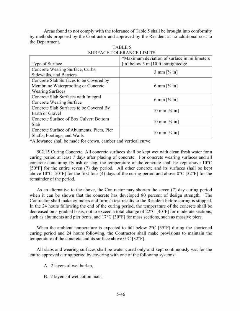
Areas found to not comply with the tolerance of Table 5 shall be brought into conformity by methods proposed by the Contractor and approved by the Resident at no additional cost to the Department.
TABLE 5 SURFACE TOLERANCE LIMITS
Type of Surface
*Maximum deviation of surface in millimeters [in] below 3 m [10 ft] straightedge
Concrete Wearing Surface, Curbs, Sidewalks, and Barriers 3 mm [⅛ in]
Concrete Slab Surfaces to be Covered by Membrane Waterproofing or Concrete Wearing Surfaces
6 mm [¼ in]
Concrete Slab Surfaces with Integral Concrete Wearing Surface 6 mm [¼ in]
Concrete Slab Surfaces to be Covered By Earth or Gravel 10 mm [⅜ in]
Concrete Surface of Box Culvert Bottom Slab 10 mm [⅜ in]
Concrete Surface of Abutments, Piers, Pier Shafts, Footings, and Walls 10 mm [⅜ in]
*Allowance shall be made for crown, camber and vertical curve. 502.15 Curing Concrete All concrete surfaces shall be kept wet with clean fresh water for a curing period at least 7 days after placing of concrete. For concrete wearing surfaces and all concrete containing fly ash or slag, the temperature of the concrete shall be kept above 10°C [50°F] for the entire seven (7) day period. All other concrete and its surfaces shall be kept above 10°C [50°F] for the first four (4) days of the curing period and above 0°C [32°F] for the remainder of the period. As an alternative to the above, the Contractor may shorten the seven (7) day curing period when it can be shown that the concrete has developed 80 percent of design strength. The Contractor shall make cylinders and furnish test results to the Resident before curing is stopped. In the 24 hours following the end of the curing period, the temperature of the concrete shall be decreased on a gradual basis, not to exceed a total change of 22°C [40°F] for moderate sections, such as abutments and pier bents, and 17°C [30°F] for mass sections, such as massive piers. When the ambient temperature is expected to fall below 2°C [35°F] during the shortened curing period and 24 hours following, the Contractor shall make provisions to maintain the temperature of the concrete and its surface above 0°C [32°F]. All slabs and wearing surfaces shall be water cured only and kept continuously wet for the entire approved curing period by covering with one of the following systems:
A. 2 layers of wet burlap, B. 2 layers of wet cotton mats,
5-46

C. 1 layer of wet burlap and either a polyethylene sheet or a polyethylene coated burlap blanket, D. 1 layer of wet cotton mats and either a polyethylene sheet or a polyethylene coated burlap blanket.
Except as otherwise specified, curing protection for slabs and wearing surfaces shall be applied within 30 minutes after the concrete is screeded and before the surface of the concrete has lost its surface "wetness" or "sheen" appearance. The first layer of either the burlap or the cotton mats shall be wet and shall be applied as soon as it is possible to do so without damaging the concrete surface. Polyethylene sheets shall not be placed directly on the concrete, but may be placed over the fabric cover to prevent drying. The covering of concrete wearing surfaces, decks, curbs, and sidewalks shall be kept continuously wet for the entire curing period by the use of a continuous wetting system and shall be located to insure a completely wet concrete surface for the entire curing period. All other surfaces, if not protected by forms, shall be kept thoroughly wet either by sprinkling or by the use of wet burlap, cotton mats or other suitable fabric until the end of the curing period. Polyethylene sheets shall not be placed directly on the concrete, but may be placed over the fabric cover to prevent drying. Surfaces of all concrete placements containing silica fume additive shall be coated with an approved evaporation retardant immediately after finishing and texturing the concrete surface. The application of wet burlap or wet cotton mats shall be made within 15 minutes after the finishing of the concrete surface. The application rate, the desired equipment, and the mixing and application procedures for an approved evaporation retardant shall be as designated by the manufacturer. Successive applications or heavier applications of this evaporation retardant shall be applied as necessary to retain the required surface "wetness" appearance. 502.16 Loading Structures and Opening to Traffic No superstructure concentrated loads such as structural steel beams, girders and trusses shall be placed upon finished concrete substructures until the concrete has reached its design strength. No load or work will be permitted on concrete superstructure slabs or rigid frame structures until concrete cylinders cured with the slab establish that design strength has been reached. However, after a shorter period of time the Resident may permit handwork for form construction and setting stone bridge curb. No curbing or other materials shall be stored on the bridge during the 7 day curing period, except that if handwork is permitted, curb stones may be stored in a line near to their final location until ready to be set. Neither traffic nor fill material shall be allowed on superstructures of concrete bridges or culverts until concrete cylinders cured with the slab establish that design strength has been
5-47

reached, dependent upon conditions as specified in Section 502.10 and with the approval of the Resident. No traffic will be allowed on the cured concrete of a concrete wearing surface until 24 hours after the completion of the application of protective coating for concrete surfaces. Concrete approach slabs at the end of structures may be opened to traffic or backfilled if buried, when the design strength has been reached. 502.17 Bridge Drains and Incidental Drainage. All drains shall be accurately placed at the locations shown on the Plans or authorized and adequate means provided for securely holding them in the required positions during the placing of concrete. Bridge drains shall be galvanized in accordance with Section 711.04 - Bridge Drains. The Contractor shall furnish an insulator between surfaces of galvanized and weathering steels when erecting the bridge drain support assembly. Epoxy-coated washers shall be used when the support assembly attaches to weathering steel beam webs. Drains or weep holes through abutments and retaining walls shall be pipe of the size and shape shown on the Plans and shall be of Schedule 40 PVC pipe. For the purpose of providing drainage for any moisture that may collect between the floor slab and the bituminous concrete roadway surface, approved 25 mm [1 in] inside diameter plastic tube drains shall be installed at the low points of the slab surface, adjacent to the end dam or dams. The exact location will be determined in the field by the Resident and the discharge from them shall be such as to clear the bridge seats and any other portion of the structure in their proximity. The tops of the drains shall be depressed 10 mm [⅜ in] below the surface of the slab and the outlets shall project 50 mm [2 in] below the underside of the slab. Care shall be exercised such that the drains are open after the installation of the membrane waterproofing, when it is installed. 502.18 Method of Measurement A. Structural concrete satisfactorily placed and accepted will be measured by the cubic meter [cubic yard], in accordance with the dimensions shown on the Plans or authorized changes in the Plans, or as one lump sum unit, as indicated in the Schedule of Items. Structural Concrete for any irregular shapes may be measured by the cubic meter [cubic yard] as determined from the theoretical yield of the design mix or in the case of transit mixed concrete, by delivery ticket as directed by the Resident. B. The limits to be used in determining the quantities of the aforementioned structural concrete items for arriving at a lump sum price will be as follows:
1. Structural Concrete Superstructure Slabs, Structural Concrete Roadway and Sidewalk Slabs on Steel Bridges, Structural Concrete Roadway and Sidewalk Slabs on Concrete
5-48

Bridges and Structural Concrete Superstructure T-beam Type The limits will be the entire concrete superstructure, outside to outside, both transversely and longitudinally, exclusive of concrete curbs, sidewalks, permanent transition barrier and concrete transition barriers. 2. Structural Concrete Wearing Surfaces The limits will be the entire concrete wearing surface bounded transversely by the roadway curbs and longitudinally by the extreme ends. 3. Structural Concrete Box Culverts The limits will be the entire structure, meaning the bottom floor slab, abutments, wings, superstructure floor slab and headwalls or curbs. 4. Structural Concrete, Approach Slabs The limit will be the entire approach slab or slabs, as shown on the Plans. 5. Structural Concrete, Abutments and Retaining Walls, Structural Concrete, Abutments and Retaining Walls (placed under water), Structural Concrete Piers, and Structural Concrete Piers (placed under water) The limits will be the entire concrete substructure unit or units, from the bottom of the footing to the top of the unit, and outside to outside, both transversely and longitudinally, except for the portion to be placed under water, as indicated on the Plans, which will be the limits of the concrete unit or units, outside to outside, transversely, longitudinally, and vertically. 6. Structural Concrete Rigid Frame Structures The limits will be the entire concrete structure, meaning the frame walls and top slab. Included within the limits for payment, unless otherwise shown on the Plans, are bottom slab, wing walls and headwalls. 7. Structural Concrete Culvert End walls The limit will be the entire concrete end wall or end walls, as shown on the Plans. 8. Structural Concrete Curb and Sidewalks The limit will be the entire concrete curb or sidewalk, as shown on the Plans. 9. Concrete Fill Will be measured for payment by the number of cubic meters [cubic yards] of concrete, in place, to the vertical pay limits shown on the Plans. If the Contractor elects to omit forms, then any excavation or concrete placed beyond the pay limits indicated on the Plans shall not be paid for, but shall be at the Contractor’s expense.
C. No deduction will be made for the volume of concrete displaced by structural steel, reinforcing steel, pile heads, expansion joint material, drains, chamfers on corners, inset panels of 38 mm [1 ½ in] or less in depth, pipes, weep holes and authorized openings for utilities of 0.2 m³ [¼ yd³] or less in volume, when any of these items occur in structural concrete which is to be paid for on a cubic meter [cubic yard] basis. D. When the bottom of foundations for concrete structures is required to be at a definite elevation within rock excavation, as shown on the Plans or otherwise designated, the quantity to be measured will be the number of cubic meters [cubic yards] of concrete actually and
5-49
satisfactorily placed above a plane at 300 mm [1 ft] below the above specified plan elevation and within the neat lines of the structure as shown on the Plans or on authorized changes in the Plans. If the ledge rock is excavated below the plane at 300 mm [1 ft] below the plan elevation, without authorization, then this space shall be replaced with concrete of the same composition as required for the structure foundation but will not be measured for payment.
E. For the purposes of making pay adjustments under Method A, quantities of lots and sublots shall be determined as outlined under Section 502.0502 - Quality Assurance Method A, and under Section 502.19 - Basis of Payment.
502.19 Basis of Payment The accepted work done under structural concrete, of the classes and for the types of work required, will be paid for at the Contract unit price per cubic meter [cubic yard], or at the Contract lump sum price, for the respective Contract items involved. Payment for both the unit price and the lump sum price items will be full compensation for furnishing and installing bridge drains, water stops, expansion joint filler, PVC or plastic tube drains, asphalt roll roofing (roofing felt), asphalt for painting or covering various type of joints, all required sandblasting, bonding, curing and joint sealing and all incidentals necessary to complete the work satisfactorily. No direct payment will be made for concrete admixtures. No price adjustments will be made to the lump sum bid for the respective items that are bid lump sum, except when quantity changes are directed by the Department. It will be the responsibility of the Contractor to verify the estimated quantities prior to submitting bid documents. Payment for structural concrete culvert connection shall include drilling and grouting the dowels into the existing headwall and excavation. Reinforcing will be paid for under Pay Item 503.12, Reinforcing Steel, Fabricated and Delivered and Pay Item 503.13, Reinforcing Steel, Placing. Reinforcing steel, railings, stone curbing and any material that may be required for bridge lighting systems, will be measured and paid for separately as provided in the appropriate sections. Implementation of the Quality Control Plan and costs associated with acceptance test sampling shall be incidental. All costs associated with obtaining, testing and evaluating drilled core specimens for dispute resolution will not be paid for directly, but will be considered incidental to related items. Pay adjustments will be made only for cast-in-place concrete accepted under Method A. Pay adjustments shall be computed on the actual final quantity for unit price items. Pay adjustments shall be computed on the estimated quantity for lump sum items, except when precast deck panels are used, or when quantity changes are directed by the Department. When precast deck panels are used, the precast deck panel quantity, as computed from the Working Drawings, shall be deducted from the estimated lump sum quantity to determine the new estimated quantity that will be used to compute pay adjustments. When Department-directed quantity changes are made, this quantity shall be added to, or subtracted from, the estimated
5-50

lump sum quantity to determine the new estimated quantity that will be used to compute pay adjustments. When precast deck panels are used and Department-directed quantity changes are made under the same lump sum item, the combined quantity change shall be added to, or subtracted from, the estimated lump sum quantity to determine the new estimated lump sum quantity that will be used to compute pay adjustments. Pay adjustments will be made according to the formulas in Sections 502.191 through 502.194. P, the unit value for pay adjustment purposes, is specified in Special Provision Section 502, Structural Concrete (QC/QA Acceptance Methods). P values, as specified in Special Provision Section 502, reflect the price per cubic meter (yd3) for all pay adjustment purposes. 502.191 Pay Adjustment for Compressive Strength Compressive strength tests will be completed by the Department in accordance with AASHTO-T22 at 28 days. If three consecutive tests fail to meet the below listed strength requirements, the Contractor shall submit remedial actions acceptable to the Department, at no additional cost. These remedial actions shall be taken until the source of the problem can be identified and corrected or new trial batches can be performed. When the average of three consecutive tests falls to less than 1.0 MPa [150 psi] above the specified strength or any single test more than 1.4 MPa [200 psi] below the specified strength, the Resident will notify the Contractor to make corrective changes in the materials, mix proportions, or in the concrete manufacturing procedures before placing additional concrete of the same class. Such changes shall be subject to the approval of the Resident. The lot pay adjustment for compressive strength will be as follows: Pay factors (PF) for sublot pay adjustments for compressive strength per sublot will be determined as specified below.
TABLE 6
Class Compressive Strength Pay Factor (PF) {Metric} Pay Factor (PF) [US Customary] A >30 MPa [4350 psi] 1 1
27 - 30 MPa [3900 - 4350 psi] (0.10/3) x (strength) (0.10/450) x (strength) + 0.0333 <27MPa[3900 psi] (0.10/3) x (strength) (0.10/450) x (strength) + 0.0333 LP >35 MPa [ 5075 psi] 1 1
32 - 35 MPa [4575 - 5075 psi] (0.10/3) x (strength)-0.1667 (0.10/500) x (strength) - 0.0150 <32MPa [4575 psi] (0.10/3) x (strength) -0.1667 (0.10/500) x (strength) - 0.0150
S > 20 MPa [2900 psi] 1 1 17 - 20 MPa [2600 - 2900 psi] (0.10/3) x (strength) +0.3333 (0.10/300) x (strength) + 0.0333 <17MPa [2600 psi] (0.10/3) x (strength) +0.3333 (0.10/300) x (strength)+ 0.0333
The pay adjustment per sublot for compressive strength will be as follows: Sublot Pay Adjustment = P x (PF - 1) x Sublot Size
No positive pay adjustments for compressive strength will be made.
5-51
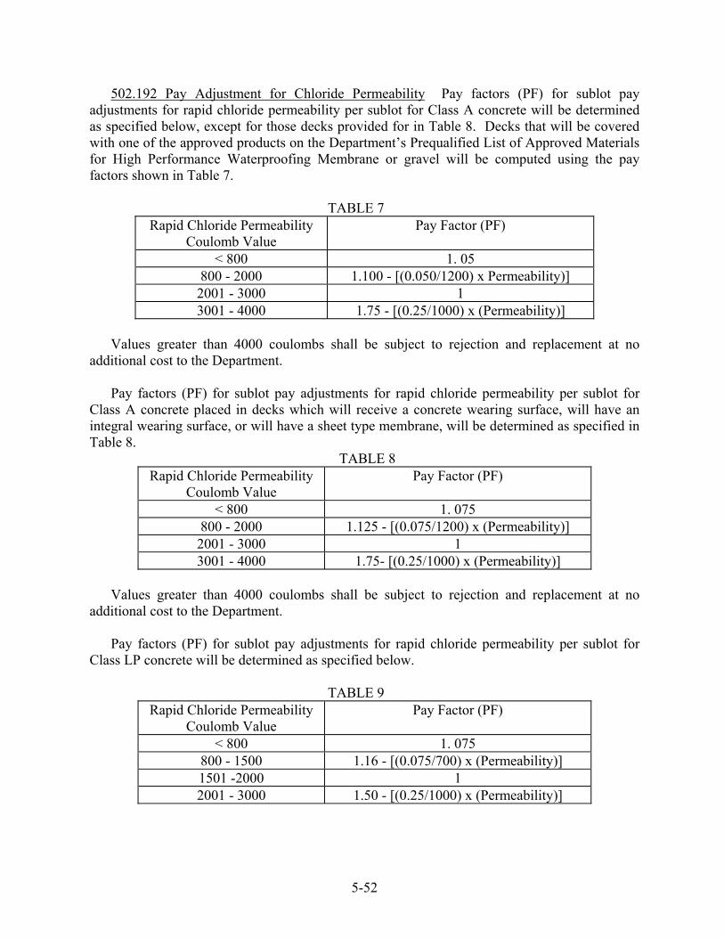
502.192 Pay Adjustment for Chloride Permeability Pay factors (PF) for sublot pay adjustments for rapid chloride permeability per sublot for Class A concrete will be determined as specified below, except for those decks provided for in Table 8. Decks that will be covered with one of the approved products on the Department’s Prequalified List of Approved Materials for High Performance Waterproofing Membrane or gravel will be computed using the pay factors shown in Table 7.
TABLE 7 Rapid Chloride Permeability
Coulomb Value Pay Factor (PF)
< 800 1. 05 800 - 2000 1.100 - [(0.050/1200) x Permeability)] 2001 - 3000 1 3001 - 4000 1.75 - [(0.25/1000) x (Permeability)]
Values greater than 4000 coulombs shall be subject to rejection and replacement at no additional cost to the Department.
Pay factors (PF) for sublot pay adjustments for rapid chloride permeability per sublot for Class A concrete placed in decks which will receive a concrete wearing surface, will have an integral wearing surface, or will have a sheet type membrane, will be determined as specified in Table 8.
TABLE 8 Rapid Chloride Permeability
Coulomb Value Pay Factor (PF)
< 800 1. 075 800 - 2000 1.125 - [(0.075/1200) x (Permeability)] 2001 - 3000 1 3001 - 4000 1.75- [(0.25/1000) x (Permeability)]
Values greater than 4000 coulombs shall be subject to rejection and replacement at no additional cost to the Department. Pay factors (PF) for sublot pay adjustments for rapid chloride permeability per sublot for Class LP concrete will be determined as specified below.
TABLE 9 Rapid Chloride Permeability
Coulomb Value Pay Factor (PF)
< 800 1. 075 800 - 1500 1.16 - [(0.075/700) x (Permeability)] 1501 -2000 1 2001 - 3000 1.50 - [(0.25/1000) x (Permeability)]
5-52

Values greater than 3000 coulombs shall be subject to rejection and replacement at no additional cost to the Department. The pay adjustment per sublot for rapid chloride permeability will be as follows: Sublot Pay Adjustment = P x (PF - 1) x Sublot Size 502.193 Pay Adjustment for Air Content Pay factors (PF) for pay adjustments for air content will be determined using the Quality Level Analysis as specified in Section 106. The pay adjustment for air content will be as follows: Lot Pay Adjustment = P x (PF-1) x Lot Size The maximum allowable bonus for air content shall be 2.5 percent. 502.194 Pay Adjustments for Surface Tolerance, Alignment and Trueness, Plumb and Batter, and for Finish No positive pay adjustments will be made under this section. Negative pay adjustments will be made on a per placement basis as follows: A. Surface Tolerance When the Resident uses a 3 meter [10 ft] straightedge to measure surface tolerance and more than 15 percent of the measurements taken for any one placement exceed the maximum deviations shown in Table 5 of Section 502.14(b), a pay adjustment of 10 percent as required, will be computed according to the formula given below. When the Resident uses a lightweight profiler to measure tolerance and the International Ride Index (IRI) is in excess of 6.5 m 3.95 m/km [250 in/mile] for any one placement, a pay adjustment of 10 percent as required, will be computed as follows: Pay Adjustment = P x Placement Size x .10 B. Alignment and Trueness When alignment and trueness exceed the tolerances described in Section 502.0502, the Resident will make a pay adjustment of 10 percent as required, according to the formula given below: Pay adjustment = P x Placement Size x .10 C. Plumb and Batter The Resident will take measurements in accordance with Section 502.0502. When any one measurement is beyond the allowable limits, a pay adjustment of 10 percent as required, will be computed as follows: Pay adjustment = P x Placement Size x .10 D. Finish The Resident will take measurements to determine the areas to be repaired in accordance with Section 502.0502. When more than 5 percent and less than 10 percent of the surface of any placement requires repairs of defects or there are defects that expose reinforcing steel, a pay adjustment of 10 percent as required, will be computed as follows: Pay adjustment = P x Placement Size x .10
Payment will be made under:
5-53
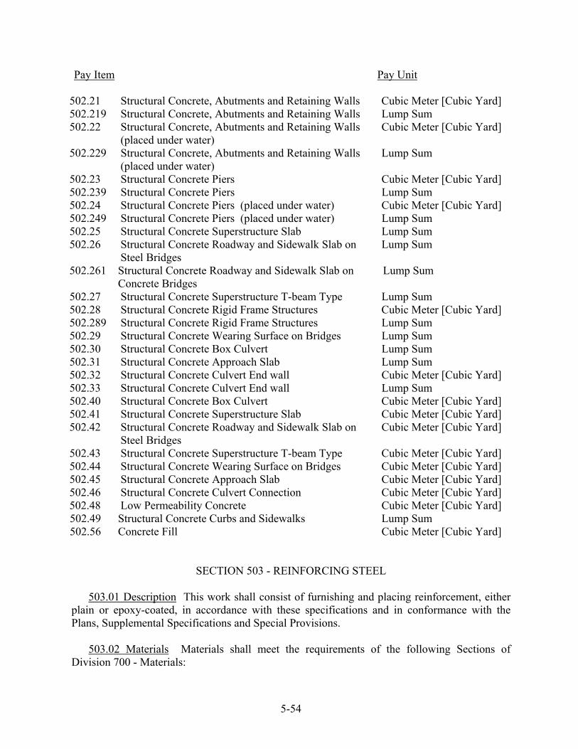
Pay Item Pay Unit
502.21 Structural Concrete, Abutments and Retaining Walls Cubic Meter [Cubic Yard] 502.219 Structural Concrete, Abutments and Retaining Walls Lump Sum 502.22 Structural Concrete, Abutments and Retaining Walls
(placed under water) Cubic Meter [Cubic Yard]
502.229 Structural Concrete, Abutments and Retaining Walls (placed under water)
Lump Sum
502.23 Structural Concrete Piers Cubic Meter [Cubic Yard] 502.239 Structural Concrete Piers Lump Sum 502.24 Structural Concrete Piers (placed under water) Cubic Meter [Cubic Yard] 502.249 Structural Concrete Piers (placed under water) Lump Sum 502.25 Structural Concrete Superstructure Slab Lump Sum 502.26 502.261
Structural Concrete Roadway and Sidewalk Slab on Steel Bridges Structural Concrete Roadway and Sidewalk Slab on Concrete Bridges
Lump Sum Lump Sum
502.27 Structural Concrete Superstructure T-beam Type Lump Sum 502.28 Structural Concrete Rigid Frame Structures Cubic Meter [Cubic Yard] 502.289 Structural Concrete Rigid Frame Structures Lump Sum 502.29 Structural Concrete Wearing Surface on Bridges Lump Sum 502.30 Structural Concrete Box Culvert Lump Sum 502.31 Structural Concrete Approach Slab Lump Sum 502.32 Structural Concrete Culvert End wall Cubic Meter [Cubic Yard] 502.33 Structural Concrete Culvert End wall Lump Sum 502.40 Structural Concrete Box Culvert Cubic Meter [Cubic Yard] 502.41 Structural Concrete Superstructure Slab Cubic Meter [Cubic Yard] 502.42 Structural Concrete Roadway and Sidewalk Slab on
Steel Bridges Cubic Meter [Cubic Yard]
502.43 Structural Concrete Superstructure T-beam Type Cubic Meter [Cubic Yard] 502.44 Structural Concrete Wearing Surface on Bridges Cubic Meter [Cubic Yard] 502.45 Structural Concrete Approach Slab Cubic Meter [Cubic Yard] 502.46 Structural Concrete Culvert Connection Cubic Meter [Cubic Yard] 502.48 502.49 502.56
Low Permeability Concrete Structural Concrete Curbs and Sidewalks Concrete Fill
Cubic Meter [Cubic Yard] Lump Sum Cubic Meter [Cubic Yard]
SECTION 503 - REINFORCING STEEL
503.01 Description This work shall consist of furnishing and placing reinforcement, either plain or epoxy-coated, in accordance with these specifications and in conformance with the Plans, Supplemental Specifications and Special Provisions.
503.02 Materials Materials shall meet the requirements of the following Sections of
Division 700 - Materials:
5-54
Reinforcing Steel 709.01 Welded Steel Wire Fabric 709.02
503.03 Schedule of Material When the Department does not furnish reinforcing steel schedules, the Contractor shall submit order lists, bending diagrams and bar layout drawings to the Resident for approval. The reinforcing steel shall not be ordered until these lists and drawings are approved. Approval shall not relieve the Contractor of full responsibility for the satisfactory completion of this item. When the Department allows the use of precast concrete deck panels, or any other significant changes that effect the quantity of reinforcing steel, the Contractor shall be responsible for revising the reinforcing steel schedule; the revised schedule shall be submitted to the Resident for approval.
503.04 Protection of Material Reinforcement, either plain or epoxy-coated, shall be stored
on skids or other supports a minimum of 300 mm [12 in] above the ground surface and protected at all times from damage and surface contamination. The storage supports shall be constructed of wood, or other material that will not damage the surface of the reinforcement or epoxy coating. Bundles of bars shall be stored on supports in a single layer. Each bundle shall be placed on the supports out of contact with adjacent bundles.
If it is expected that epoxy-coated bars will be required to be stored outdoors for a period in
excess of three months, then they shall be protected from ultraviolet radiation. 503.05 Fabrication Bending of reinforcing bars and tolerances for bending of reinforcing
bars shall be in conformance with the latest edition of the "Manual of Standard Practice of the Concrete Reinforcing Steel Institute" and the "Detailing Manual of the American Concrete Institute". Unless otherwise specifically authorized, bars shall be bent cold.
503.051 Epoxy Coating Reinforcing steel, specified on the design drawings to be epoxy
coated, shall meet the requirements of AASHTO M284/M284M (ASTM A775/A775M), Epoxy-Coated Reinforcing Steel Bars, and the following requirements:
a. The Contractor shall furnish a written certification that at the point of application of
the coating and at the reinforcing bar shop the coating, the coated bars, and the handling and packaging of the coated bars, meet all the requirements specified in Section 5.2.1 and Section 15.1 of AASHTO M284/M284M (ASTM A775/A775M), and Section 503.053 of these specifications.
b. Patching material as specified in Section 5.4 of AASHTO M284/M284M (ASTM
A775/A775M), shall be supplied for both shop and field patching of the coated reinforcing steel. The patching material shall be supplied as required, but at not less than the following rates:
#10 to #16 [#3 to #5] bars: 1 L/4800 m [1 qt/15000 ft] of bar, or fraction thereof #19 to #29 [#6 to #9] bars: 1 L/2550 m [1 qt/8000 ft] of bar, or fraction thereof #32 [#10] and up: 1 L/1900 m [1 qt/6000 ft] of bar, or fraction thereof
5-55

c. All testing shall be as specified in AASHTO M284/M284M (ASTM A775/A775M), except that the frequency of testing for adhesion of the coating shall be two bars of each size out of all bars coated with each individual batch or lot of epoxy resin, or two bars of each size out of all bars coated in an eight hour period, whichever is greater.
d. If a reinforcing bar fabrication shop uses previously stockpiled bars to supply the
requirements of this contract, the fabrication shop shall furnish copies of all certificates required to be furnished by the coating applicator under a., above. The certificates furnished shall be directly traceable to the actual bars used through batch numbers, order numbers or similar information. If such certification is not available, the Department reserves the right to perform the tests specified under AASHTO M284/M284M (ASTM A775/A775M), at the expense of the fabrication shop. For bars supplied from stock, the fabrication shop shall supply all patching material specified under b., above.
e. The Contractor shall notify the Resident at least 1 week prior to the start of the
coating application, so that the Resident or their designated representative may be present at the beginning of the application of the epoxy coating.
503.052 Patching of Epoxy Coating Patching required at the point of application of the
epoxy coating shall be done in conformance with the requirements of AASHTO M284/M284M (ASTM A775/A775M).
At the reinforcing steel fabrication shop and at the job site, all nicks, cuts, scratches, cracks,
abrasions, sheared ends etc., visible to the naked eye, shall be repaired using patching material supplied as specified under Section 503.051 b. To the greatest extent possible, repairs to each day's production at the fabrication shop and each day's placement at the job site shall be done before the end of each working day. If damaged areas do become rusted or contaminated with foreign matter, then these areas shall be cleaned by sandblasting, or an equally effective method, such that all visible rust and/or foreign matter is removed prior to patching.
503.053 Packaging and Handling of Epoxy-Coated Bars All handling of epoxy-coated
reinforcing bars by mechanical means shall be done by equipment having padded contact areas, or by the use of nylon webbing slings. The use of chains or wire rope slings shall not be allowed, even when used with padding. All bundles of coated bars shall be lifted with a strong back, spreader bar, multiple supports or a platform bridge to prevent bar-to-bar abrasion from sags in the bundles. Support points during lifting or transporting of bundled epoxy-coated bars shall be spaced at a maximum of 4.5 m [15 ft].
Bundled bars shall be strapped together with non-metallic or padded straps in a manner to
prevent bar-to-bar abrasion due to relative movement between bars. Bars loaded for transport shall be loaded and strapped down in a manner that will prevent
damage from motion and vibration, to the greatest extent possible. Bundles of bent bars shall be transported strapped to wooden platforms or shall be crated. All individual bundles and layers of bundles shall be separated, and supported by dunnage.
5-56

Individual bars shall be handled in a manner that prevents damage to the coating due to abrasion or impact, and at no time shall any bar be moved by dragging over any surface, including other reinforcing bars. Sufficient personnel shall be assigned to assure that there is complied with the above.
503.06 Placing and Fastening All steel reinforcement shall be accurately placed in the
positions shown on the plans and shall be firmly held there during the placing and setting of the concrete. Immediately before placing concrete, steel reinforcement shall be free from all foreign material, which could decrease the bond between the steel and concrete. Such foreign material shall include, but not be limited to, dirt, loose mill scale, excessive rust, paint, oil, bitumen and dried concrete mortar.
Bars shall be fastened together at all intersections except where spacing is less than 300 mm
[1 ft] in either direction, in which case, fastening at alternate intersections of each bar with other bars will be permitted providing this will hold all the bars securely in position. This fastening may be tightly twisted wire or by tack welding when permitted by the Resident. All tack welding shall be done in accordance with Section 504, Structural Steel. No tack welding for fastening or supporting reinforcing steel in areas of high tensile stresses will be permitted. Welding on epoxy-coated reinforcing steel will not be permitted under any condition.
In general, no welding will be permitted on the main reinforcing steel of superstructure
slabs. Proper distances from the forms shall be maintained by means of stays, blocks, ties, hangers
or other approved means. Blocks used for this purpose shall be precast portland cement mortar blocks of approved shape and dimensions. Chairs may be used for this purpose and, when used, must be plastic, plastic coated, epoxy coated or plastic tipped. Layers of bars may be separated by precast portland cement mortar blocks or other approved devices. The use of pebbles, pieces of broken stone or brick, metal pipe or wooden blocks shall not be permitted. The placing of reinforcement as concrete placement progresses, without definite and secure means of holding the steel in its correct position, shall not be permitted except in the case of welded steel wire fabric or bar mats.
Epoxy-coated reinforcing bars supported on formwork shall rest on coated wire bar
supports, or on bar supports made of dielectric material or other acceptable materials. Wire bar supports shall be coated with dielectric material for a minimum distance of 50 mm [2 in] from the point of contact with the reinforcing bars. Reinforcing bars used as support bars shall be epoxy-coated. In walls, spreader bars shall be epoxy-coated.
Tie wire for epoxy-coated reinforcing steel shall be soft annealed wire that has been nylon,
epoxy or plastic coated. Field bending or cutting of epoxy-coated reinforcing bars will not be allowed, unless
otherwise indicated on the plans or permitted by the Resident. When field bending or cutting is allowed, all damaged coating areas shall be repaired in accordance with the patching requirements.
5-57
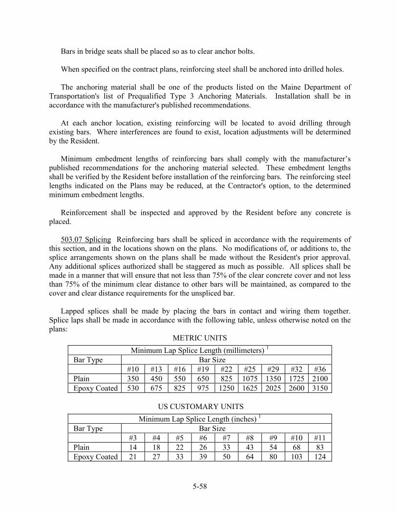
Bars in bridge seats shall be placed so as to clear anchor bolts. When specified on the contract plans, reinforcing steel shall be anchored into drilled holes. The anchoring material shall be one of the products listed on the Maine Department of
Transportation's list of Prequalified Type 3 Anchoring Materials. Installation shall be in accordance with the manufacturer's published recommendations.
At each anchor location, existing reinforcing will be located to avoid drilling through
existing bars. Where interferences are found to exist, location adjustments will be determined by the Resident.
Minimum embedment lengths of reinforcing bars shall comply with the manufacturer’s
published recommendations for the anchoring material selected. These embedment lengths shall be verified by the Resident before installation of the reinforcing bars. The reinforcing steel lengths indicated on the Plans may be reduced, at the Contractor's option, to the determined minimum embedment lengths.
Reinforcement shall be inspected and approved by the Resident before any concrete is
placed.
503.07 Splicing Reinforcing bars shall be spliced in accordance with the requirements of this section, and in the locations shown on the plans. No modifications of, or additions to, the splice arrangements shown on the plans shall be made without the Resident's prior approval. Any additional splices authorized shall be staggered as much as possible. All splices shall be made in a manner that will ensure that not less than 75% of the clear concrete cover and not less than 75% of the minimum clear distance to other bars will be maintained, as compared to the cover and clear distance requirements for the unspliced bar.
Lapped splices shall be made by placing the bars in contact and wiring them together. Splice laps shall be made in accordance with the following table, unless otherwise noted on the plans:
METRIC UNITS
Minimum Lap Splice Length (millimeters) 1 Bar Type Bar Size #10 #13 #16 #19 #22 #25 #29 #32 #36 Plain 350 450 550 650 825 1075 1350 1725 2100 Epoxy Coated 530 675 825 975 1250 1625 2025 2600 3150
US CUSTOMARY UNITS
Minimum Lap Splice Length (inches) 1 Bar Type Bar Size #3 #4 #5 #6 #7 #8 #9 #10 #11 Plain 14 18 22 26 33 43 54 68 83 Epoxy Coated 21 27 33 39 50 64 80 103 124
5-58

1 Lap Splice lengths are based on the following parameters: Minimum center-to-center spacing between bars of 150 mm [6 in]; nominal yield strength of the reinforcing steel of 420 MPa [60 ksi]; minimum 28-day compressive strength of concrete of 30 MPa [4350 psi]. When any of the preceding parameters is altered, appropriate minimum lap splice lengths will be determined by the Resident. When lap splices are placed horizontally in an element where the concrete depth below the splice will be 300 mm [12 in], or more, the indicated lap splice lengths shall be multiplied by a factor of 1.4.
Mechanical couplers may be used for splicing reinforcing bars, provided they are approved
by the Resident and conform to the following requirements: a. Tension Couplers Couplers shall be able to develop 1.25 times the theoretical yield strength of the spliced bar in tension. Bolted and wedge-lock type couplers will not be allowed. b. Compression Couplers Couplers shall be capable of maintaining the spliced bars in alignment prior to and during concrete placement. For reinforcing bars designed to act in compression, the individual bar ends shall be within 1½° of being "square" to the final 300 mm [12 in] of the bar. Additionally, abutting bar ends shall be in contact, and the angle of the gap between abutting bar ends shall be 3°, or less. c. Mechanical Couplers Any mechanical couplers using a threaded splicer and dowel in combination, requiring a lapped splice with the reinforcing bars, shall have a minimum lap splice length as required by this Section. Welded splices may be made by the "Thermit" process or, with the approval of the Resident,
by the shielded metal arc welding process or the self-shielded flux-core arc welding process. The latter two processes shall be used in strict conformance with the requirements of the latest edition of AWS D1.4 "Structural Welding Code - Welding Reinforcing Steel" and any applicable provisions of Section 504, Structural Steel. The Contractor shall submit complete details of their proposed method of making welded splices for the Resident's approval.
503.08 Lapping Sections of welded steel wire fabric shall securely fasten to adjoining sections and overlap. All laps shall be in accordance with Wire Reinforcement Institute Manual of Standard Practice.
Bar mats shall be spliced as required for the individual bars. 503.09 Substitution Substitution of different size bars shall not be permitted except with the
written authorization of the Resident. 503.10 Method of Measurement Reinforcing steel, both plain and epoxy-coated, shall be
measured by the computed number of kilograms [pounds] of steel reinforcement authorized. Welded steel wire fabric shall be measured by the computed number of kilograms [pounds] of fabric authorized. Splices made using mechanical devices or by welding, as shown on the plans
5-59
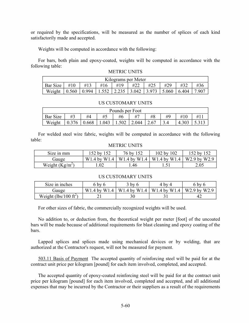
or required by the specifications, will be measured as the number of splices of each kind satisfactorily made and accepted.
Weights will be computed in accordance with the following: For bars, both plain and epoxy-coated, weights will be computed in accordance with the
following table: METRIC UNITS
Kilograms per Meter Bar Size #10 #13 #16 #19 #22 #25 #29 #32 #36 Weight 0.560 0.994 1.552 2.235 3.042 3.973 5.060 6.404 7.907
US CUSTOMARY UNITS
Pounds per Foot Bar Size #3 #4 #5 #6 #7 #8 #9 #10 #11 Weight 0.376 0.668 1.043 1.502 2.044 2.67 3.4 4.303 5.313
For welded steel wire fabric, weights will be computed in accordance with the following
table: METRIC UNITS
Size in mm 152 by 152 76 by 152 102 by 102 152 by 152 Gauge W1.4 by W1.4 W1.4 by W1.4 W1.4 by W1.4 W2.9 by W2.9
Weight (Kg/m2) 1.02 1.46 1.51 2.05
US CUSTOMARY UNITS
Size in inches 6 by 6 3 by 6 4 by 4 6 by 6 Gauge W1.4 by W1.4 W1.4 by W1.4 W1.4 by W1.4 W2.9 by W2.9
Weight (lbs/100 ft2) 21 30 31 42 For other sizes of fabric, the commercially recognized weights will be used. No addition to, or deduction from, the theoretical weight per meter [foot] of the uncoated
bars will be made because of additional requirements for blast cleaning and epoxy coating of the bars.
Lapped splices and splices made using mechanical devices or by welding, that are
authorized at the Contractor's request, will not be measured for payment. 503.11 Basis of Payment The accepted quantity of reinforcing steel will be paid for at the
contract unit price per kilogram [pound] for each item involved, completed, and accepted. The accepted quantity of epoxy-coated reinforcing steel will be paid for at the contract unit
price per kilogram [pound] for each item involved, completed and accepted, and all additional expenses that may be incurred by the Contractor or their suppliers as a result of the requirements
5-60

in these specifications will be considered incidental to, and included in, the contract unit price per kilogram [pound].
Payment for work associated with revisions to the reinforcing steel schedule, required when
the Department allows the use of precast concrete deck panels, or any other significant changes that effect the quantity of reinforcing steel, shall be considered incidental to related contract items.
The accepted quantity of welded steel wire fabric will be paid for at the contract unit price
per kilogram [pound], in place, completed and accepted. The accepted quantity of mechanical and/or welded splices will be paid for at the contract
unit price each, completed and accepted, for each type specified. Payment will not be made for any materials used to hold reinforcement in place or for extra
weight due to substitutions and splices made for the Contractor's convenience. When reinforcing steel is specified to be anchored into drilled holes, no additional payment
will be made for drilling and anchoring reinforcing steel or cutting of reinforcing steel to embedment lengths.
Payment for additional material samples, as required for testing by the Department, shall be
considered incidental to related contract items. Payment will be made under:
Pay Item Pay Unit
503.12 Reinforcing Steel, Fabricated and Delivered Kilogram [Pound] 503.13 Reinforcing Steel, Placing Kilogram [Pound] 503.14 Epoxy-Coated Reinforcing Steel, Kilogram [Pound] Fabricated and Delivered 503.15 Epoxy-Coated Reinforcing Steel, Placing Kilogram [Pound] 503.16 Welded Steel Wire Fabric, Complete in place Kilogram [Pound] 503.17 Mechanical/Welded Splice Each
SECTION 504 - STRUCTURAL STEEL
504.01 Description This work shall consist of detailing, fabricating and erecting structural steel bridges, ancillary bridge products and other steel structures.
504.02 Materials Materials shall meet the requirements of the following Sections of Division 700-Materials: Structural Steel 713.01
5-61
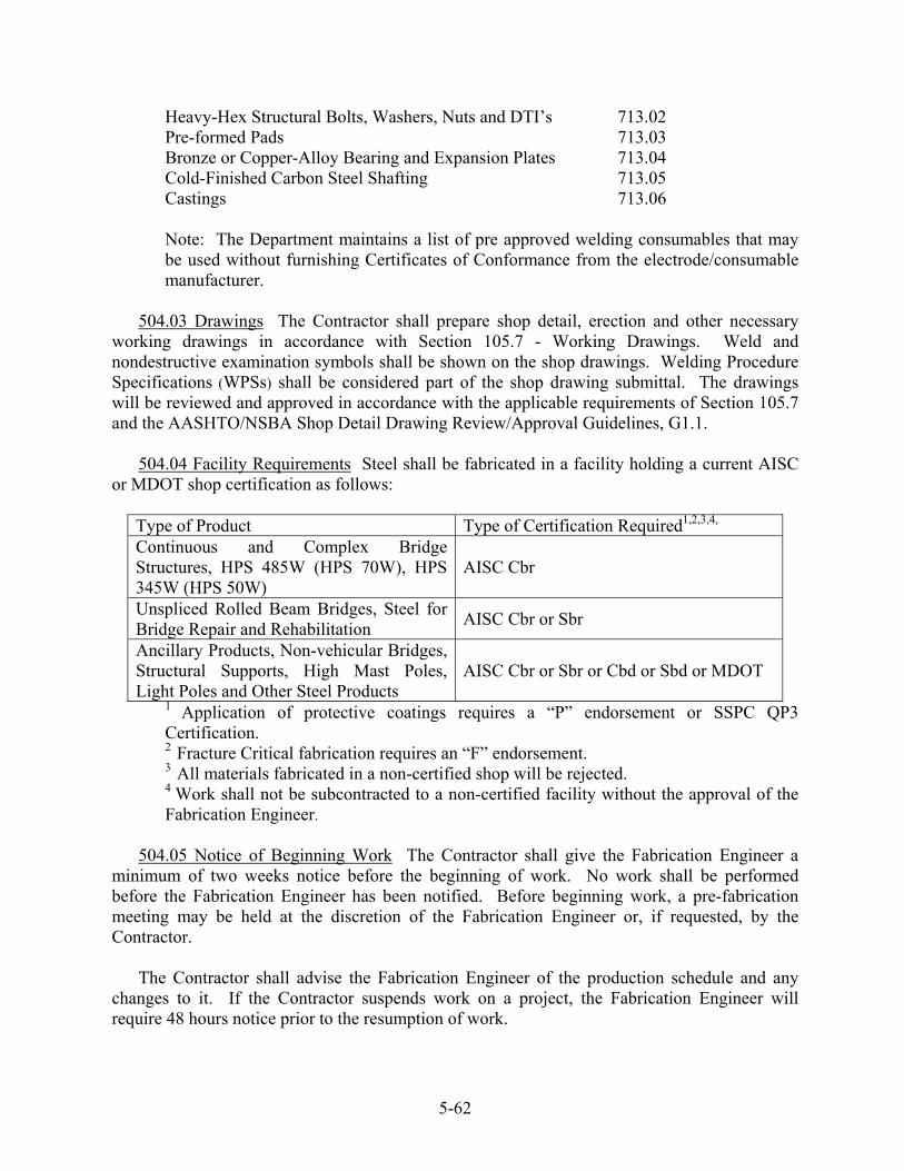
Heavy-Hex Structural Bolts, Washers, Nuts and DTI’s 713.02 Pre-formed Pads 713.03 Bronze or Copper-Alloy Bearing and Expansion Plates 713.04 Cold-Finished Carbon Steel Shafting 713.05 Castings 713.06 Note: The Department maintains a list of pre approved welding consumables that may be used without furnishing Certificates of Conformance from the electrode/consumable manufacturer.
504.03 Drawings The Contractor shall prepare shop detail, erection and other necessary working drawings in accordance with Section 105.7 - Working Drawings. Weld and nondestructive examination symbols shall be shown on the shop drawings. Welding Procedure Specifications (WPSs) shall be considered part of the shop drawing submittal. The drawings will be reviewed and approved in accordance with the applicable requirements of Section 105.7 and the AASHTO/NSBA Shop Detail Drawing Review/Approval Guidelines, G1.1.
504.04 Facility Requirements Steel shall be fabricated in a facility holding a current AISC or MDOT shop certification as follows:
Type of Product Type of Certification Required1,2,3,4,
Continuous and Complex Bridge Structures, HPS 485W (HPS 70W), HPS 345W (HPS 50W)
AISC Cbr
Unspliced Rolled Beam Bridges, Steel for Bridge Repair and Rehabilitation AISC Cbr or Sbr
Ancillary Products, Non-vehicular Bridges, Structural Supports, High Mast Poles, Light Poles and Other Steel Products
AISC Cbr or Sbr or Cbd or Sbd or MDOT
1 Application of protective coatings requires a “P” endorsement or SSPC QP3 Certification.
2 Fracture Critical fabrication requires an “F” endorsement. 3 All materials fabricated in a non-certified shop will be rejected.
4 Work shall not be subcontracted to a non-certified facility without the approval of the Fabrication Engineer.
504.05 Notice of Beginning Work The Contractor shall give the Fabrication Engineer a
minimum of two weeks notice before the beginning of work. No work shall be performed before the Fabrication Engineer has been notified. Before beginning work, a pre-fabrication meeting may be held at the discretion of the Fabrication Engineer or, if requested, by the Contractor.
The Contractor shall advise the Fabrication Engineer of the production schedule and any changes to it. If the Contractor suspends work on a project, the Fabrication Engineer will require 48 hours notice prior to the resumption of work.
5-62

504.06 Inspection Quality Control (Q.C.) is the responsibility of the Contractor. The Quality Control Inspector (Q.C.I.) shall inspect all aspects of the work and shall supervise all nondestructive examination (NDE). The Q.C.I. shall record measurements and test results in a clear and legible manner. The Q.C.I. shall reject materials and workmanship that do not meet contract requirements. The Contractor may perform NDE in addition to the minimum required. The results of all measurements and testing shall be made available to the Quality Assurance Inspector (Q.A.I.).
Quality Assurance (Q.A.) is the prerogative of the Fabrication Engineer. The Q.A.I. will ensure that the Q.C. Department is performing properly, verify documentation, periodically inspect workmanship and witness NDE. Q.A. testing deemed necessary by the Fabrication Engineer in addition to the minimum testing requirements shall be scheduled to minimize interference with the production schedule.
504.07 Inspector's Authority The Q.A.I. will have the authority to reject material or
workmanship that does not meet the contract requirements. The acceptance of material or workmanship by the Q.A.I. will not prevent subsequent rejection, if found unacceptable.
504.08 Rejections Rejected material and workmanship shall be corrected or replaced by the Contractor.
504.09 Facilities for Inspection The Contractor shall provide a private office at the fabrication plant for inspection personnel authorized by the Department. The office shall have an area not less than 9.3 m² [100 ft2] and shall be in close proximity to the work. The office shall be climate controlled to maintain the temperature between 18° C [65° F] and 30° C [85° F], lighted and have the exit(s) closed by a door(s) equipped with a lock and 2 keys which shall be furnished to the Inspector(s). The office shall be equipped with a desk or table having a minimum size of 1200 by 760 mm [48 in by 30 in], 2 chairs, a telephone, telephone answering machine, line data port, plan rack and 2-drawer letter size file cabinet with a lock and 2 keys which shall be furnished to the Inspector(s).
The facilities and all furnishings shall remain the property of the Contractor upon completion of the work. Payment for the facilities, heating, lighting, telephone installation, basic monthly telephone charges and all furnishings shall be incidental to the contract.
504.10 Mill Orders and Mill Test Reports The Contractor shall provide a copy of the material mill orders. The Contractor shall provide Certified Mill Test Reports (CMTRs) for all material. The CMTRs shall include chemical and mechanical properties as well as the results of CVN testing, when required. CMTRs shall originate from the producer of the steel. The CMTRs shall be provided prior to the beginning of fabrication.
504.11 Material Identification and Control Structural steel plates and shapes shall be marked as specified in AASHTO M 160M/M 160(ASTM A 6/A 6M). Material from stock shall only be used if it can be positively identified, properly documented and the direction of rolling can be determined, when necessary.
5-63

Material shall be stored above the ground and shall be kept free from dirt, grease and other foreign material. Steel shall be protected from significant corrosion.
Fasteners shall be organized and stored by size and production lot to facilitate sampling.
Fasteners shall be stored in a protected environment that preserves the fastener lubricant.
504.12 Protective Coatings Paint, metallizing and fusion-bonded coatings shall be applied in accordance with Section 506 and/or the plans as applicable.
Galvanizing shall be done in accordance with AASHTO M 111 (ASTM A 123). Steel shall be abrasive blast cleaned to SSPC SP-6/NACE No. 3 before galvanizing. Fasteners shall be galvanized in accordance with AASHTO M 232 (ASTM A 153) or AASHTO M 298 Class 50 (ASTM B 695 Class 50). Galvanized nuts shall be lubricated with a water-soluble lubricant containing a dye that contrasts with the color of the galvanizing.
504.13 Unpainted Steel Products fabricated from weathering steel shall remain in the bare,
unpainted condition, unless otherwise noted on the plans. All surfaces shall be cleaned to a minimum SSPC SP-6/NACE No. 3, Commercial Blast Cleaning.
HIGHWAY BRIDGE FABRICATION
504.14 Materials for Bridges Bridge steel shall meet the requirements of AASHTO M 270M/M 270 (ASTM A 709/A 709M). The grade of steel shall be designated on the plans.
504.15 Design Bridge design, detail and load requirements shall conform to Division 1, Design, of the AASHTO LRFD Bridge Design Specifications, applicable Interim Specifications, and these Specifications.
504.16 Fabrication Fabrication shall be in accordance with the ANSI/AASHTO/AWS D1.5 Bridge Welding Code (the D1.5 Code), as modified herein, and these Specifications.
Material shall be handled in a manner that prevents nicks, gouges or other damage from chains, wire ropes or other handling devices during all phases of fabrication.
504.17 Nondestructive Examination Nondestructive examination shall be performed in accordance with the D1.5 Code. The Q.A.I will witness all nondestructive examination. The Contractor shall give the Q.A.I. twenty-four hours notice to facilitate the Q.A.I.’s presence. Nondestructive examination shall be documented on the appropriate forms from Annex III of the D1.5 Code or an equivalent form prepared by the user.
504.18 Plates for Fabricated Members Plates subject to calculated stress, including splice plates, shall be cut so that the direction of rolling is parallel to the primary stresses. The direction of primary stresses for web material is parallel to the flanges unless otherwise shown. Heat numbers shall be transferred to all primary bridge material and maintained until it is incorporated in a piece-marked member.
5-64
Ends of flange plates that are to be butt-welded shall be scanned for laminations by ultrasonic straight beam testing (UT) in accordance with ASTM A 898/A 898M as modified herein. The plate shall be scanned a distance of 300 mm [12 in] from the ends prior to welding.
The acceptance standard shall be Level I. Repairs to laminations within 300 mm [12 in] of
butt welds shall have the prior approval of the Fabrication Engineer.
504.19 Correcting Materials Steel may be corrected by any method that does not damage the material. If heating of the steel is required, it shall be done in accordance with a written procedure approved by the Fabrication Engineer.
Following corrective work, the steel shall be carefully inspected using nondestructive examination (NDE) methods acceptable to the Fabrication Engineer. The presence of cracks or fractures shall be cause for rejection of the material.
For general use, a Contractor may submit a procedure for correcting camber or sweep by heating for pre-qualification by the Fabrication Engineer.
504.20 Base Metal Repairs Base metal repairs that require welding shall not be made without the approval of the Fabrication Engineer.
504.21 Thermal Cutting Steel shall be thermal cut with automatic equipment or with a mechanical guide. The rate of travel of the cutting equipment shall be adjusted to prevent hardening the steel. Freehand cutting is not allowed.
504.22 Edge Hardness Thermal cut edges of cover plates, flange plates and splice material other than ASTM A 36/A 36M shall have an average hardness not exceeding Rockwell C30 and no individual reading shall exceed Rockwell C35. Hardness shall be measured at approximately mid-thickness of the plate and the spacing of the measurements shall be at both ends, quarter points and midpoint unless additional testing is required by the Q.A.I. One measurement shall consist of the average of three readings taken at each location. Hardness readings and locations shall be documented by the Q.C.I.
Excessive hardness shall be removed by the application of heat, by grinding or machining. Heating shall be done only with the approval of the Fabrication Engineer.
504.23 Edge Planing Sheared edges of plates greater than 16 mm [⅝ in] thick for use as flanges, cover plates, bearing stiffeners and splice material shall be planed to a depth of 5 mm [3/16 in].
504.24 Bent Plates Cold-bent, rolled steel plates shall conform to the following:
(a) The bend line will be at right angles to the direction of rolling. (b) The radius of bends shall be such that no cracking of the plate occurs. Minimum
radii, measured to the concave face of the metal, are shown in the following table:
5-65
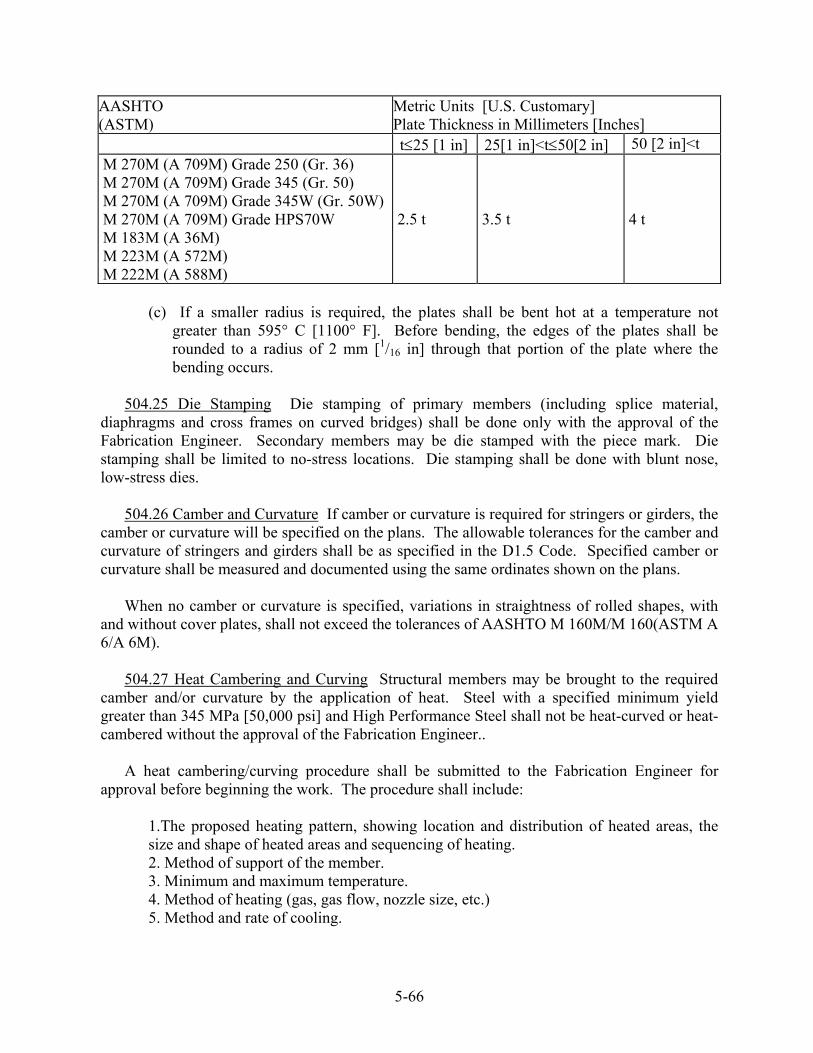
AASHTO (ASTM)
Metric Units [U.S. Customary] Plate Thickness in Millimeters [Inches]
t≤25 [1 in] 25[1 in]<t≤50[2 in] 50 [2 in]<t M 270M (A 709M) Grade 250 (Gr. 36) M 270M (A 709M) Grade 345 (Gr. 50) M 270M (A 709M) Grade 345W (Gr. 50W) M 270M (A 709M) Grade HPS70W M 183M (A 36M) M 223M (A 572M) M 222M (A 588M)
2.5 t 3.5 t 4 t
(c) If a smaller radius is required, the plates shall be bent hot at a temperature not
greater than 595° C [1100° F]. Before bending, the edges of the plates shall be rounded to a radius of 2 mm [1/16 in] through that portion of the plate where the bending occurs.
504.25 Die Stamping Die stamping of primary members (including splice material,
diaphragms and cross frames on curved bridges) shall be done only with the approval of the Fabrication Engineer. Secondary members may be die stamped with the piece mark. Die stamping shall be limited to no-stress locations. Die stamping shall be done with blunt nose, low-stress dies.
504.26 Camber and Curvature If camber or curvature is required for stringers or girders, the camber or curvature will be specified on the plans. The allowable tolerances for the camber and curvature of stringers and girders shall be as specified in the D1.5 Code. Specified camber or curvature shall be measured and documented using the same ordinates shown on the plans.
When no camber or curvature is specified, variations in straightness of rolled shapes, with and without cover plates, shall not exceed the tolerances of AASHTO M 160M/M 160(ASTM A 6/A 6M).
504.27 Heat Cambering and Curving Structural members may be brought to the required camber and/or curvature by the application of heat. Steel with a specified minimum yield greater than 345 MPa [50,000 psi] and High Performance Steel shall not be heat-curved or heat-cambered without the approval of the Fabrication Engineer..
A heat cambering/curving procedure shall be submitted to the Fabrication Engineer for approval before beginning the work. The procedure shall include:
1.The proposed heating pattern, showing location and distribution of heated areas, the size and shape of heated areas and sequencing of heating. 2. Method of support of the member. 3. Minimum and maximum temperature. 4. Method of heating (gas, gas flow, nozzle size, etc.) 5. Method and rate of cooling.
5-66
Steel shall be blast cleaned to SSPC SP-6/NACE No. 3 prior to heating. Both flanges and webs shall be heated with a minimum of two torches (one torch on either side of the member). Restraining or jacking the member before or during heating shall be done only with the approval of the Fabrication Engineer. The Contractor shall submit calculations showing that the nominal bending stress in the member does not exceed 0.60 Fy if restraint or jacking is proposed.
The target temperature shall be 595º C [1100º F]. Steel heated in excess of 675°C [1250° F] will be subject to rejection. The temperature of the steel shall be measured using temperature indicating crayons applied to the heated area approximately 10-15 seconds after the torch is removed. Alternate methods of measuring the temperature may be used with the approval of the Fabrication Engineer.
For camber, the heated area of the web shall be a “V” with a 10-15 degree included angle extending full web depth less 50 mm [2 in]. The heated area of the flange shall be rectangular and centered over the base of the triangle. Web heating shall begin at the apex of the triangle and proceed toward the base using the ½ lap technique. Flange heating shall begin immediately after completion of the web. Backtracking is not allowed.
Curving may be performed by a combination of line heats applied to the edge of both flanges simultaneously using an automatic track torch(es) and "V" heats, or by "V" heats alone. If the Contractor elects to use line heating, the steel shall be allowed to cool to ambient temperature before the beginning of "V" heats. When using "V" heats, the heated area shall have an included angle of 15-30 degrees and a height 65% the flange width. The Contractor shall apply heat to adjacent areas on both flanges and both sides of the flanges simultaneously.
Following the application of heat, the steel shall be allowed to cool in still air to below 315ºC [600ºF] after which compressed air may be used. Quenching will not be allowed. All cambering and curving, including corrections, shall be carried out in the presence of the Q.A.I. Heating a structural member without the Q.A.I. present shall be cause for rejection. Camber and sweep shall be measured for acceptance after the steel has reached ambient temperature.
Areas of suspected cracking shall be tested by an NDE method satisfactory to the Fabrication Engineer. The cost of NDE examination required by the Fabrication Engineer after heat curving or cambering shall be incidental to the contract.
504.28 Welding AASHTO M 270M/M 270 (ASTM A 709/A 709M),Gr. 250, Gr. 345, Gr. 345W Weld Procedure Specifications (WPSs) for groove welds and multiple-pass fillet welds shall be qualified by Procedure Qualification Testing in accordance with the D1.5 Code. The electrical parameters shall be within the consumable manufacturer’s published recommendations.
Each side of complete joint penetration welds, once begun, shall be welded to completion without interruption or a delay between passes except as necessary to maintain interpass temperature requirements. When backgouging is required, the groove and 75 mm [3 in] on
5-67

either side of the groove shall be preheated to 51° C [125° F] immediately before the resumption of welding.
Single-pass fillet welds may be qualified by a Fillet Weld Soundness Test performed in accordance with the D1.5 Code as modified herein. The “T” test shall be performed by welding the smallest fillet weld to be used in production on one side and the largest fillet weld used in production on the other side of the “T”. The test specimens shall be macroetch tested in accordance with the requirements of Section 5 of the D1.5 Code. Acceptance and re-testing, if required, shall be in accordance with Section 5 of the D1.5 Code.
The minimum heat input for single-pass fillet welds during testing and production shall be
1.4 kilojoules/mm [35 kilojoules/in].
504.29 Welding AASHTO M 270M/M 270 (ASTM A 709/A 709M) HPS 345W (HPS 50W) and HPS 485W (HPS 70W) Steel Consumables shall be handled and stored in accordance with Subsections 12.6.5, and 12.6.6 of the D1.5 Code.
Filler metals for joining HPS 345W (HPS 50W) to HPS 345W (HPS 50W) or Grade 345W (Grade 50W) base metal shall meet the requirements of Table 4.1 or Table 4.2 of the D1.5 Code for Grade 345W (Grade 50W) steel.
Filler metals for welding HPS 485W (HPS 70W) base metal shall meet the following requirements:
Unless otherwise specified on the Plans, filler metals for fillet welds joining HPS 485W (HPS 70W) to HPS 485W (HPS 70W), HPS 345W (HPS 50W) or Grade 345W (Grade 50W) shall meet the matching filler metal requirements of Table 4.1 of the D1.5 Code for Grade 345W (Grade 50W) steel (H8 maximum). Single-pass fillet welds joining HPS 485W (HPS 70W) to HPS 345W (HPS 50W) or Grade 345W (Grade 50W) steel shall meet the requirements of Section 4.1.5 of the D1.5 Code. Single-pass fillet welds need not meet the requirements for exposed bare application. Filler metals for multiple-pass fillet welds joining HPS 485W (HPS 70W) to either HPS 485W (HPS 70W), HPS 345W (HPS 50W) or Grade 345W shall meet the requirements of Table 4.3 of the D1.5 Code for Grade 345W (Grade 50W) steel (H8 maximum). Filler metals for groove welds joining HPS 485W (HPS 70W) to HPS 345W (HPS 50W) or Grade 345W (Grade 50W) shall meet the matching filler metal requirements for Grade 345W (Grade 50W) steel (H8 maximum) as listed in Table 4.1 of the D1.5 Code. Matching filler metal for HPS 485W (HPS 70W) shall meet the following requirements:
5-68
(a) AWS Classification F9A4-EXXX-X with the optional supplemental diffusible hydrogen designator of H2 or H4 and a minimum of 1% Nickel. In addition to the Procedure Qualification Test, diffusible hydrogen (Hd) tests shall be performed on the weld metal. The deposited weld metal shall have a diffusible hydrogen level of 4mL/100g [0.0048 gal/lb] or less. Hd shall be prepared at the fabrication facility and tested in accordance with AWS A4.3. (b) Matching SMAW electrodes shall meet the requirements of E9018RHZ and have an optional diffusible hydrogen designator of H2, H4, or H8. Undermatching SMAW electrodes shall meet the requirements of undermatching filler metals form Tables 4.1 or 4.3 of the D1.5 Code as applicable. (c) As an alternative, HPS 485W (HPS 70W) base metal may be welded by the SAW process using the consumables and reduced preheat temperatures specified in Appendix A of the AASHTO Guide Specification for Highway Bridge Fabrication with HPS70W Steel, September, 2000.
Procedure Qualification Tests for HPS 345W (HPS 50W) shall be performed in accordance with Section 5 of the D1.5 Code except that the backing bar may be Grade 345W (0.025 S max.) or HPS 345W (HPS 50W).
Weld Procedure Specifications for butt welds and multiple-pass fillet welds joining HPS 345W (HPS 50W) to HPS 345W (HPS 50W) shall be written based on the results of approved Procedure Qualification Tests performed on HPS 345W (HPS 50W) base metal.
Weld Procedure Specifications for single-pass fillet welds joining HPS 345W (HPS 50W) to HPS 345W (HPS 50W) or Grade 345W (grade 50) may be written based upon an approved Procedure Qualification Test performed on Grade 345W (Grade 50W) base metal.
Procedure Qualification Tests for HPS 485W (HPS 70W) shall be performed in accordance with Section 5 of the D1.5 Code except that the backing bar may be Grade 345W (0.025 S max.) or HPS 485W (HPS 70W). The heat input range developed by testing shall be between 1.6 kJ/mm and 3.5 kJ/mm [40 kJ/in and 90 kJ/in].
SAW and SMAW processes are approved for welding HPS 485W (HPS 70W). FCAW and GMAW processes shall be subject to approval by the Fabrication Engineer.
The results of a Procedure Qualification Test performed with HPS 485W (HPS 70W) and matching filler metal shall meet or exceed the Base Metal Requirements of AASHTO M 270M/M 270 (ASTM A 709/A 709M) for HPS 485W (HPS 70W) Steel.
Weld Procedure Specifications for fillet welds on HPS 485W (HPS 70W) using under-matched filler metals shall be written based upon an approved Procedure Qualification Test performed on HPS 345W (HPS 50W) or Grade 345W (Grade 50W) test plates.
5-69

Weld tabs for butt joints joining HPS 485W (HPS 70W) shall meet the requirements of Section 3.12 of the D1.5 Code except that the minimum length shall be 150 mm [6 in].
When welding HPS 485W (HPS 70W) steel to HPS 485W (HPS 70W) steel, preheat and
interpass temperatures shall meet the requirements of Table 4.4 of the D1.5 Code for Grade 485W (Grade 70W) base metal. When welding HPS 485W (HPS 70W) steel to HPS 345W (HPS 50W) or Gr. 345W steel, the minimum preheat temperature shall meet the requirements of Table 4.4 of the D1.5 Code for the applicable grade and thickness of the base metals.
Nondestructive Examination of HPS 485W (HPS 70W) steel shall be performed in accordance with Section 6 as modified herein. Inspectors and NDT Technicians shall be qualified in accordance with Section 12 of the D1.5 Code. Fillet weld repairs shall be inspected in accordance with Subsection 12.16.2.3 of the D1.5 Code. Cooling time prior the inspection shall be in accordance with Subsection 12.16.4 of the D1.5 Code. 504.30 Welded Fabrication A copy of an approved Welding Procedure Specification (WPS) for the joint being welded shall be displayed at each welding station. Only WPSs bearing the approval stamp of the Maine Department of Transportation shall be used.
Flange plate and web plate butt joints, web to flange welds, stiffener and connection plate to web welds, and cover plate to flange welds shall be made using an automatic or semi-automatic weld process.
Repairs to welds shall be made with the same process used for the original welds, except that repairs less than 300 mm [12 in] in length may be made with a different process using an approved WPS.
Runoff tabs shall be removed and butt welds shall be ground smooth prior to nondestructive
examination. Butt welds joining plates of equal thickness shall be ground flush with the base metal. Butt welds joining plates of unequal thickness shall be ground at a slope of 1:2.5. Butt joints joining plates of unequal width shall have a smooth transition with a minimum 600 mm [24 in] radius. Grinding marks shall be parallel to the direction of the primary stresses.
Weld metal deposited without an approved WPS or outside the parameters of an approved WPS shall be removed and rewelded as directed by the Fabrication Engineer.
504.31 Shop Assembly Abutting members shall be placed in their exact relative field position for erection and shall be assembled with the associated filler and splice material. The Q.C.I. shall record all measurements necessary to demonstrate that the shop assembly meets the requirements of the plans and Specifications. The Q.A.I. shall be given the opportunity to verify the measurements prior to disassembly.
504.32 Tolerances Dimensional tolerances for welded plate girders shall be as described in the D1.5 Code. Dimensional tolerances for rolled shapes shall be as described in AASHTO M 160 M/M 160 (ASTM A6/A 6M).
5-70

Layout and fit-up tolerances for plate girders and rolled stringers shall be as described in the D1.5 Code. The tolerance for the length of any primary bridge member shall be ±6 mm [¼ in]. The bearing- to-bearing tolerance shall be ±3 mm [⅛ in]. Abutting joints at field splices shall have an opening of 6 mm [¼ in] ± 3 mm [⅛ in].
504.33 Match marking Drill assembled or ream assembled parts shall be match marked prior to disassembly. The match marks shall be preserved through field erection.
504.34 Holes for High Strength Bolts Holes for connections may be sub-punched and reamed, sub-drilled and reamed, or drilled full-size with all the splice material assembled in final position. Holes that are reamed shall be sub-punched or sub-drilled 5 mm [3/16 in] smaller than the nominal diameter of the bolts. After assembly, the splices shall be reamed 2 mm [1/16 in] larger than the nominal bolt diameter. The Contractor may drill holes full size in each piece separately, provided that after drilling, all connections are fully assembled, duplicating the final position of the stringers or girders, to demonstrate the accuracy of the holes. Splice plates that have been drilled full size may be used as one-time templates to drill webs and flanges. The plates shall remain with the splice. Plates damaged while being used as a template shall be replaced.
Holes for cross frames, diaphragms and associated connection plates may be punched when the thickness of the plate is not greater than 20 mm [9/16 in] for AASHTO M 270M/M 270 (ASTM A 709/A 709M, Grade 250) steel and 16 mm [⅝ in] for AASHTO M 270M/M 270 (ASTM A 709/A 709M, Grade 345 and Grade 345W). The diameter of the die shall not exceed the diameter of the punch by more than 2 mm [1/16 in]. Holes shall be clean cut, without torn or ragged edges. When the material is thicker than the above limits, punching is not allowed.
Holes shall be cylindrical and perpendicular to the member. Burrs caused by drilling or reaming shall be removed from all parts.
Oversize or short-slotted holes may be used in connections other than splices of primary members and end connections of floor beams. Hardened washers shall be used over oversize and slotted holes.
Thermal cut holes in bearing plate material shall be produced using an automatic or mechanically guided process. The surface roughness shall not exceed ANSI 25µm [1000 µin].
504.35 Accuracy of Holes After assembling all parts of a connection containing sub-punched or sub-drilled holes, it shall be possible to enter a pin 3 mm [⅛ in], smaller in diameter than the nominal size of the hole in at least 75 percent of the contiguous holes in the array. When assembled, all holes in a connection shall be able to pass a pin 5 mm [3/16 in] smaller in diameter than the nominal size of the sub-punched or sub-drilled holes. Pins shall be entered perpendicular to the face of the member and no drifting will be allowed. Failure to comply with either of the above criteria shall be cause for rejection of the splice material.
5-71
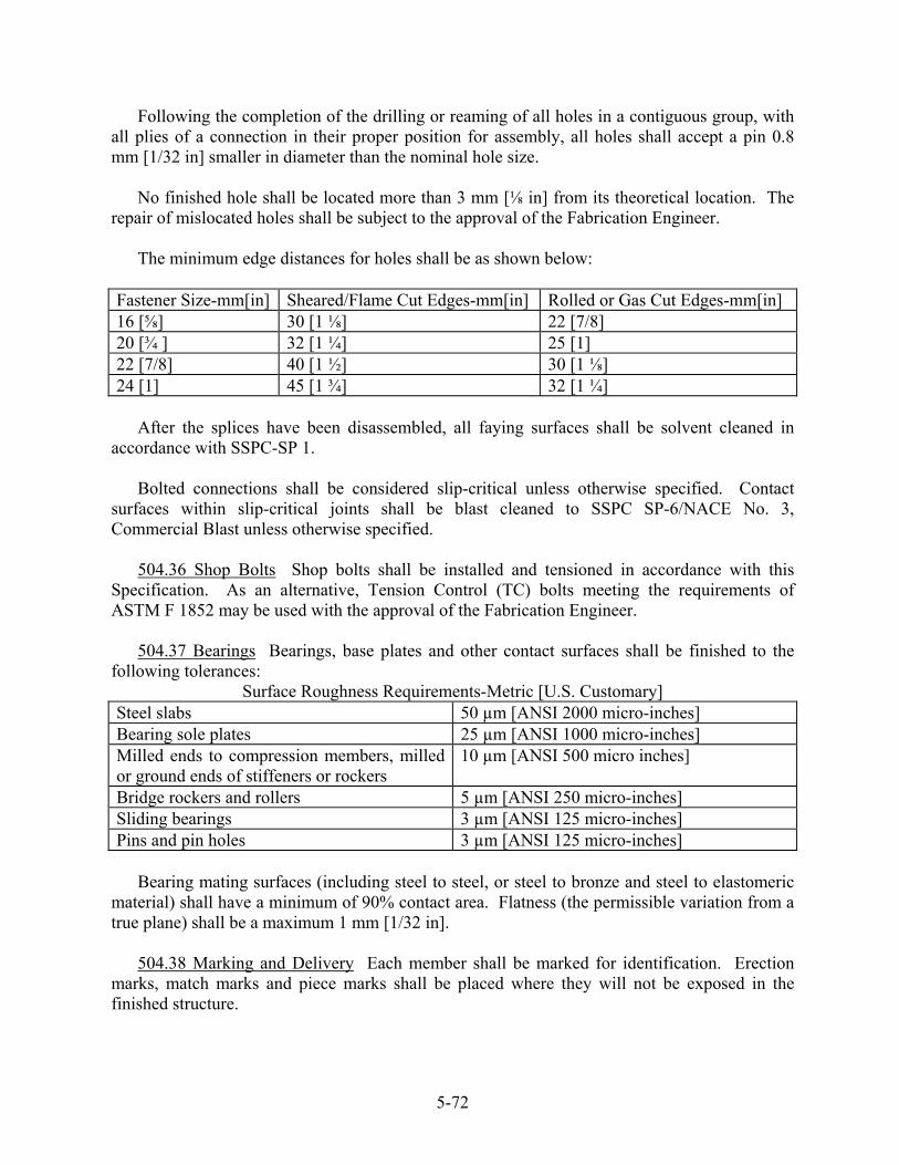
Following the completion of the drilling or reaming of all holes in a contiguous group, with all plies of a connection in their proper position for assembly, all holes shall accept a pin 0.8 mm [1/32 in] smaller in diameter than the nominal hole size.
No finished hole shall be located more than 3 mm [⅛ in] from its theoretical location. The repair of mislocated holes shall be subject to the approval of the Fabrication Engineer.
The minimum edge distances for holes shall be as shown below:
Fastener Size-mm[in] Sheared/Flame Cut Edges-mm[in] Rolled or Gas Cut Edges-mm[in] 16 [⅝] 30 [1 ⅛] 22 [7/8] 20 [¾ ] 32 [1 ¼] 25 [1] 22 [7/8] 40 [1 ½] 30 [1 ⅛] 24 [1] 45 [1 ¾] 32 [1 ¼]
After the splices have been disassembled, all faying surfaces shall be solvent cleaned in
accordance with SSPC-SP 1.
Bolted connections shall be considered slip-critical unless otherwise specified. Contact surfaces within slip-critical joints shall be blast cleaned to SSPC SP-6/NACE No. 3, Commercial Blast unless otherwise specified.
504.36 Shop Bolts Shop bolts shall be installed and tensioned in accordance with this Specification. As an alternative, Tension Control (TC) bolts meeting the requirements of ASTM F 1852 may be used with the approval of the Fabrication Engineer.
504.37 Bearings Bearings, base plates and other contact surfaces shall be finished to the following tolerances:
Surface Roughness Requirements-Metric [U.S. Customary] Steel slabs 50 µm [ANSI 2000 micro-inches] Bearing sole plates 25 µm [ANSI 1000 micro-inches] Milled ends to compression members, milled or ground ends of stiffeners or rockers
10 µm [ANSI 500 micro inches]
Bridge rockers and rollers 5 µm [ANSI 250 micro-inches] Sliding bearings 3 µm [ANSI 125 micro-inches] Pins and pin holes 3 µm [ANSI 125 micro-inches]
Bearing mating surfaces (including steel to steel, or steel to bronze and steel to elastomeric
material) shall have a minimum of 90% contact area. Flatness (the permissible variation from a true plane) shall be a maximum 1 mm [1/32 in].
504.38 Marking and Delivery Each member shall be marked for identification. Erection marks, match marks and piece marks shall be placed where they will not be exposed in the finished structure.
5-72
The Contractor shall furnish the Fabrication Engineer copies of shipping documents and erection diagrams.
Bolts of one length and diameter, along with the required number of nuts and washers shall be packed together in heavy-duty waterproof containers. Each container shall have a list and description of the contained material, including the identifying shipping lot number and Rotational-Capacity lot number, in a waterproof envelope, firmly attached to the outside of the container.
504.39 Handling and Storing Materials Material shall be placed and supported above the ground. They shall be kept clean and properly drained. Fabricated members shall be supported in a manner that will prevent injury due to excessive deflection or torsion. Care shall be exercised to prevent gouges, scratches and other damage. Chains and wire rope slings shall not be used in direct contact with fabricated members when being lifted or transported. Steel members shall be loaded, transported and unloaded at their destination without damage.
BRIDGE STEEL ERECTION
504.40 Plans If fabrication and erection of the superstructure are done under separate
contracts, the Department will furnish detailed plans for the bridge or bridges to the Contractor.
504.41 Methods and Equipment The Contractor shall submit to the Fabrication Engineer plans for any false work and/or for modifications to an existing structure necessitated by construction loading. The false work and/or modifications shall be designed, constructed and maintained for the loads placed upon it. False work calculations and design shall be stamped by a Professional Fabrication Engineer. The approval of the Fabrication Engineer shall not relieve the Contractor of the responsibility for the safety of the method, equipment or from carrying out the work in accordance with the plans and Specifications. No work shall be done without the Fabrication Engineer’s approval.
504.42 Bearings, Expansion Devices, and Anchorages Bearings shall be installed in accordance with Section 523 - Bearings.
504.43 Assembling Steel The steel shall be assembled as shown on the plans. Surfaces in permanent contact shall be cleaned before assembly. Drift pins shall be used in both the webs and flanges of connections to assure alignment of all holes. A minimum of eight drift pins shall be used in each flange and web connection. No less than 50% of the bolts in each contiguous group shall be installed and snugged before the member is released from the crane. Drift pins shall not be removed until bolts have been installed and snugged in the remaining holes.
504.44 Connections Using High Strength Bolts The Contractor shall provide all necessary torque and power wrenches, calibration equipment, feeler gauges and labor required for the testing, calibration, installation and inspection of high strength bolts. A tension measuring device (Skidmore-Wilhelm or approved equal) and torque wrench, both of which have been calibrated within 12 months and are in good condition, shall be provided by the Contractor.
5-73

Both the tension measuring device and the torque wrench shall remain at the job site during steel erection.
Each torque wrench shall have a maximum capacity approximately 100% greater than the anticipated job torque. Torque wrenches shall be equipped with a dial face gauge and a memory pointer that remains at the applied torque reading. Torque wrenches shall be graduated in increments not to exceed two percent of the maximum capacity of the wrench and shall be readable to one percent of the maximum capacity.
If Direct Tension Indicators (DTI’s) are used, a Technical Representative from the DTI manufacturer or supplier shall be present during initial testing of the DTI’s.
504.45 Bolts, Nuts, Washers and Direct Tension Indicators Bolts, nuts and washers shall be furnished by one supplier and, when practicable, shall be from one manufacturer. DTI’s shall be supplied from one manufacturer and, when practicable, from one production lot.
The manufacturer or supplier shall perform a Rotational Capacity Test (RCT) in accordance with AASHTO M 164M/M 164 (ASTM A 325/ A 325M) for each combination of bolts, nuts and washers supplied. Each combination shall be assigned a unique Rotational Capacity (R-C) lot number. The Contractor shall provide the results of the RCT to the Fabrication Engineer before installation of the fasteners.
Fasteners shall be protected from dirt and moisture. Only as many fasteners as anticipated to be installed during a work shift shall be taken from protected storage. Fasteners not used shall be returned to protected storage at the end of the workday. Fasteners that have become rusted or dirty shall be cleaned and lubricated prior to installation with a lubricant recommended by the bolt supplier or manufacturer. Tension Control (TC) fasteners shall only be re-lubricated by the manufacturer.
Surfaces in contact with the bolt head and nut shall not have a slope more than 1 to 20 with respect to a plane normal to the bolt axis. Where an outer face of the bolted parts has a slope of more than 1 to 20 with respect to a plane normal to the bolt axis, a hardened beveled washer shall be used. Bolted parts shall fit solidly together when assembled. When assembled, all joint surfaces shall be free of mill scale, dirt, burrs, or other material that would prevent solid seating of the parts. .
Bolts shall be installed with a hardened washer under the element turned in tightening. Hardened washers are required over slotted and oversize holes. Washers must completely cover holes.
Fasteners shall be tightened within 48 hours of installation. All fasteners in a connection shall be tightened to at least 105% of the Minimum Bolt Tension values in Table 1.
When DTI’s are used, the installation of DTI’s under the turned element of the fastener assembly shall be done only with the approval of the Fabrication Engineer.
5-74
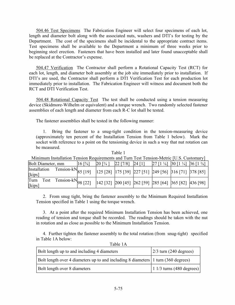
504.46 Test Specimens The Fabrication Engineer will select four specimens of each lot, length and diameter bolt along with the associated nuts, washers and DTI’s for testing by the Department. The cost of the specimens shall be incidental to the appropriate contract items. Test specimens shall be available to the Department a minimum of three weeks prior to beginning steel erection. Fasteners that have been installed and later found unacceptable shall be replaced at the Contractor’s expense.
504.47 Verification The Contractor shall perform a Rotational Capacity Test (RCT) for each lot, length, and diameter bolt assembly at the job site immediately prior to installation. If DTI’s are used, the Contractor shall perform a DTI Verification Test for each production lot immediately prior to installation. The Fabrication Engineer will witness and document both the RCT and DTI Verification Test.
504.48 Rotational Capacity Test The test shall be conducted using a tension measuring device (Skidmore-Wilhelm or equivalent) and a torque wrench. Two randomly selected fastener assemblies of each length and diameter from each R-C lot shall be tested.
The fastener assemblies shall be tested in the following manner: 1. Bring the fastener to a snug-tight condition in the tension-measuring device (approximately ten percent of the Installation Tension from Table 1 below). Mark the socket with reference to a point on the tensioning device in such a way that nut rotation can be measured.
Table 1 Minimum Installation Tension Requirements and Turn Test Tension-Metric [U.S. Customary]
Bolt Diameter, mm 16 [⅝] 20 [¾ ] 22 [7/8] 24 [1] 27 [1 ⅛] 30 [1 ¼] 36 [1 ⅜] Installation Tension-kN[kips]
85 [19] 125 [28] 175 [39] 227 [51] 249 [56] 316 [71] 378 [85]
Turn Test Tension-kN[kips]
98 [22] 142 [32] 200 [45] 262 [59] 285 [64] 365 [82] 436 [98]
2. From snug tight, bring the fastener assembly to the Minimum Required Installation Tension specified in Table 1 using the torque wrench.
3. At a point after the required Minimum Installation Tension has been achieved, one reading of tension and torque shall be recorded. The readings should be taken with the nut in rotation and as close as possible to the Minimum Installation Tension.
4. Further tighten the fastener assembly to the total rotation (from snug-tight) specified in Table 1A below:
Table 1A Bolt length up to and including 4 diameters 2/3 turn (240 degrees)
Bolt length over 4 diameters up to and including 8 diameters 1 turn (360 degrees)
Bolt length over 8 diameters 1 1/3 turns (480 degrees)
5-75

5. The tension at the specified rotation above shall be equal to or greater than the Turn Test Tension (see Table 1). Record the tension. 6. Upon completion of steps 1 through 5:
(a.) The torque measured in step 3. to produce the measured tension shall not exceed the value obtained by the following equation:
METRIC
Torque ≤340 PD Where: Torque = Measured Torque (N.mm) P = Measured Bolt Tension (N) D = Nominal Bolt Diameter (mm)
U.S. CUSTOMARY
Torque ≤ 0.25PD Where: Torque = Measured Torque (ft.-lbs.) P = Measured Bolt Tension (lbs.) D = Nominal Bolt Diameter (feet)
(b) If the torque measured in step 3 exceeds the torque calculated in step 6, all fasteners from the lot represented shall be re-lubricated and retested.
7. Bolts that are too short to be assembled in the tension-measuring device shall be
tested in a steel joint. Mark the turned element relative to the steel joint in such a manner that fastener rotation can be measured. Use the torque wrench to bring the fastener assembly from a snug-tight condition to 1/3 turn. Record the torque required to reach that rotation while the turned element is in motion. The torque thus determined shall not exceed the maximum torque requirement using the formula in step 6., assuming P to be equal to the appropriate Turn Test Tension from Table 1. Further tighten the fastener assembly to 2/3 turn from the initial mark. Assemblies that fail before 2/3 rotation either by stripping or fracture fail the test.
8. Disassemble each fastener assembly and run the nut down the full length of the threads excluding the grip length. If evidence is found of torsional failure, shear failure or stripping of the threads, the assembly shall be deemed to have failed the test. Slight necking in the grip length is not considered a failure. 9. Bolts used for the Rotational Capacity Test shall be discarded.
504.49 DTI Verification Test When Direct Tension Indicators are used, a DTI Verification
Test shall be performed at the job site. The Verification Test shall be performed for each production lot of DTIs in combination with each R-C lot of fasteners. The test shall be performed in two steps:
5-76
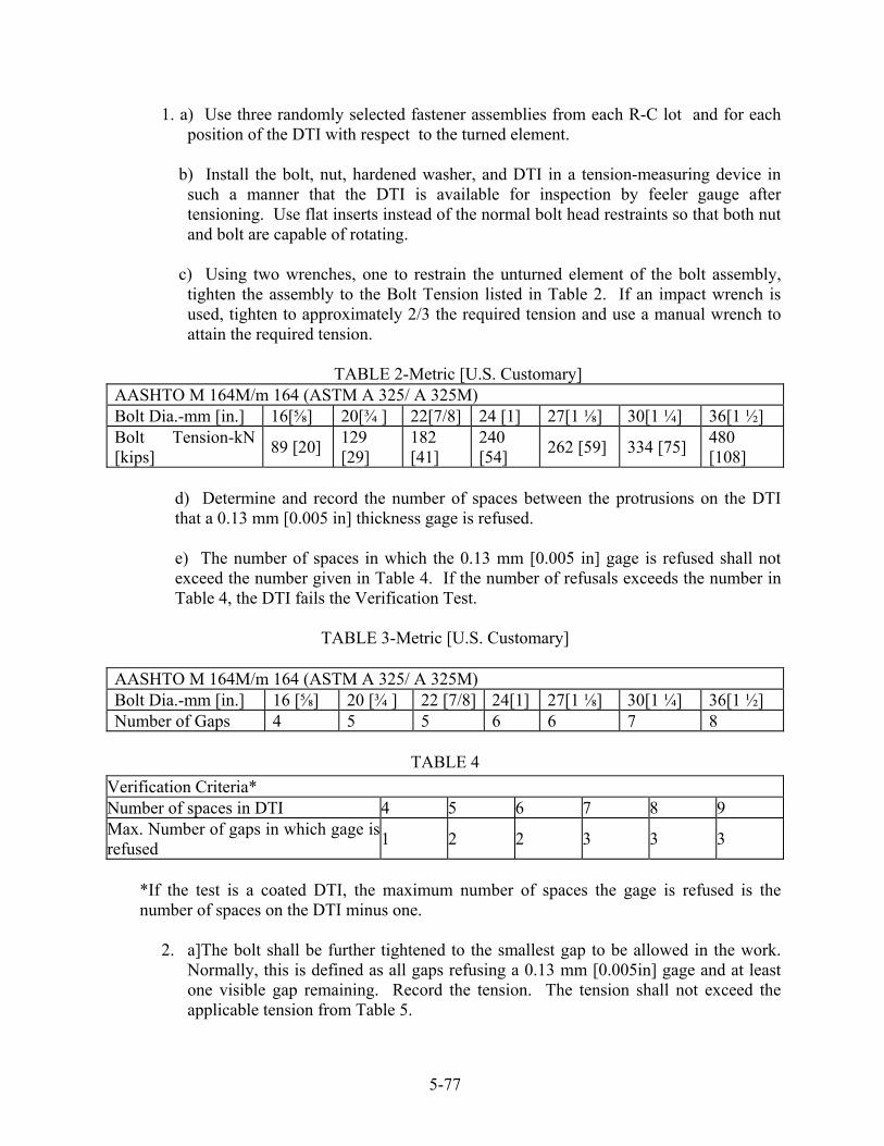
1. a) Use three randomly selected fastener assemblies from each R-C lot and for each position of the DTI with respect to the turned element.
b) Install the bolt, nut, hardened washer, and DTI in a tension-measuring device in
such a manner that the DTI is available for inspection by feeler gauge after tensioning. Use flat inserts instead of the normal bolt head restraints so that both nut and bolt are capable of rotating.
c) Using two wrenches, one to restrain the unturned element of the bolt assembly,
tighten the assembly to the Bolt Tension listed in Table 2. If an impact wrench is used, tighten to approximately 2/3 the required tension and use a manual wrench to attain the required tension.
TABLE 2-Metric [U.S. Customary]
AASHTO M 164M/m 164 (ASTM A 325/ A 325M) Bolt Dia.-mm [in.] 16[⅝] 20[¾ ] 22[7/8] 24 [1] 27[1 ⅛] 30[1 ¼] 36[1 ½] Bolt Tension-kN [kips] 89 [20] 129
[29] 182 [41]
240 [54] 262 [59] 334 [75] 480
[108]
d) Determine and record the number of spaces between the protrusions on the DTI that a 0.13 mm [0.005 in] thickness gage is refused.
e) The number of spaces in which the 0.13 mm [0.005 in] gage is refused shall not exceed the number given in Table 4. If the number of refusals exceeds the number in Table 4, the DTI fails the Verification Test.
TABLE 3-Metric [U.S. Customary]
AASHTO M 164M/m 164 (ASTM A 325/ A 325M) Bolt Dia.-mm [in.] 16 [⅝] 20 [¾ ] 22 [7/8] 24[1] 27[1 ⅛] 30[1 ¼] 36[1 ½] Number of Gaps 4 5 5 6 6 7 8
TABLE 4
Verification Criteria* Number of spaces in DTI 4 5 6 7 8 9 Max. Number of gaps in which gage isrefused
1 2 2 3 3 3
*If the test is a coated DTI, the maximum number of spaces the gage is refused is the number of spaces on the DTI minus one.
2. a]The bolt shall be further tightened to the smallest gap to be allowed in the work. Normally, this is defined as all gaps refusing a 0.13 mm [0.005in] gage and at least one visible gap remaining. Record the tension. The tension shall not exceed the applicable tension from Table 5.
5-77
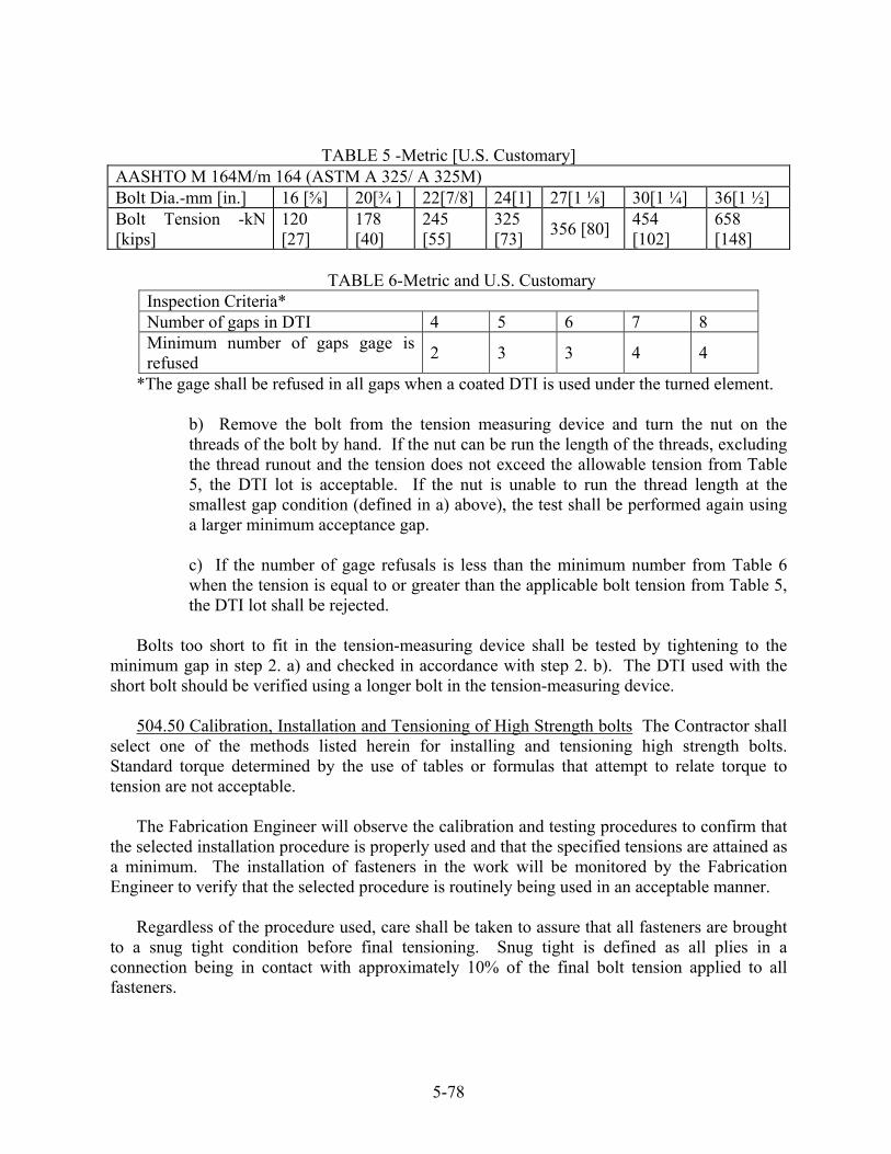
TABLE 5 -Metric [U.S. Customary] AASHTO M 164M/m 164 (ASTM A 325/ A 325M) Bolt Dia.-mm [in.] 16 [⅝] 20[¾ ] 22[7/8] 24[1] 27[1 ⅛] 30[1 ¼] 36[1 ½] Bolt Tension -kN [kips]
120 [27]
178 [40]
245 [55]
325 [73] 356 [80] 454
[102] 658 [148]
TABLE 6-Metric and U.S. Customary
Inspection Criteria* Number of gaps in DTI 4 5 6 7 8 Minimum number of gaps gage is refused 2 3 3 4 4
*The gage shall be refused in all gaps when a coated DTI is used under the turned element.
b) Remove the bolt from the tension measuring device and turn the nut on the threads of the bolt by hand. If the nut can be run the length of the threads, excluding the thread runout and the tension does not exceed the allowable tension from Table 5, the DTI lot is acceptable. If the nut is unable to run the thread length at the smallest gap condition (defined in a) above), the test shall be performed again using a larger minimum acceptance gap.
c) If the number of gage refusals is less than the minimum number from Table 6 when the tension is equal to or greater than the applicable bolt tension from Table 5, the DTI lot shall be rejected.
Bolts too short to fit in the tension-measuring device shall be tested by tightening to the
minimum gap in step 2. a) and checked in accordance with step 2. b). The DTI used with the short bolt should be verified using a longer bolt in the tension-measuring device.
504.50 Calibration, Installation and Tensioning of High Strength bolts The Contractor shall select one of the methods listed herein for installing and tensioning high strength bolts. Standard torque determined by the use of tables or formulas that attempt to relate torque to tension are not acceptable.
The Fabrication Engineer will observe the calibration and testing procedures to confirm that the selected installation procedure is properly used and that the specified tensions are attained as a minimum. The installation of fasteners in the work will be monitored by the Fabrication Engineer to verify that the selected procedure is routinely being used in an acceptable manner.
Regardless of the procedure used, care shall be taken to assure that all fasteners are brought to a snug tight condition before final tensioning. Snug tight is defined as all plies in a connection being in contact with approximately 10% of the final bolt tension applied to all fasteners.
5-78

High Strength bolts shall be installed and tensioned by: (1) the Calibrated Wrench method, (2) the Turn of Nut method, (3) with Direct Tension Indicators or (4) Alternative Design Fasteners.
504.51 Installation A Hardened washer shall be installed under the turned element. Fastener assemblies shall be installed in all holes in a contiguous group, except for holes containing drift pins, and shall be brought to a snug tight condition, progressing systematically from the most severely restrained location in a connection to the free edges. Drift pins shall not be removed until enough bolts have been tightened to prevent slippage in the joint. Tightening shall progress systematically from the most rigid part of the joint to the free edges.
504.52 Tightening Tightening of fasteners shall be done by one of the following:
1. The Calibrated Wrench Method Adjustable pneumatic wrenches, adjustable hydraulic wrenches or calibrated torque wrenches may be used. Each wrench used shall be calibrated.
The Calibrated Wrench method for tensioning bolts shall be calibrated at least once each
shift for fastener assemblies of each diameter, length, and R-C lot being installed. Three fastener assemblies (bolt, nut and washer) for each diameter and length shall be
randomly selected for wrench calibration.
Install each of the three fastener assemblies in the tension-measuring device and install enough washers so at least three but no more than five threads are showing. A hardened washer shall be under the turned element. Snug the bolt using the same procedure to be used during installation.
When the calibrated wrench is an adjustable pneumatic wrench or an adjustable
hydraulic wrench, the wrench shall be set so that each of the three assemblies shall be tightened from snug to less than 105% of the Minimum Bolt Tension specified in Table 1.
When a manual torque wrench is used, the torque required to tension each of the three
bolts to 105% of the Minimum Bolt Tension specified in Table 1 shall be recorded. The job installation torque shall be the average of the three recorded torque values. The torque shall be measured with turned element in rotation.
When bolts are too short to fit in the tension measuring device, the wrenches shall be
calibrated using DTI’s. The DTI’s must first be calibrated as described in Section 504.49.
Following the snug tightening operation, calibrated wrenches shall be operated until the wrench cuts out at the setting established by calibration or manual torque wrenches shall be used to bring the bolt assembly to the job installation torque as a minimum. Torque shall be measured with the turned element in rotation. The wrench shall be returned to “touch up” previously tightened fasteners that may have relaxed because of subsequent tightening.
5-79

2. The “Turn of Nut” Method The Turn of Nut method shall be calibrated once, prior to fastener installation, for each diameter and length bolt of each R-C lot.
Select a random sample of three fastener assemblies of each diameter, length and R-C
lot. Install each assembly in a tension-measuring device, using the snugging procedure to be used in the work. Mark the nut or socket to a reference point on the tension-measuring device and further tighten the bolt to the required rotation in Table 6. The bolt tension shall be a minimum of 105% of the Minimum Bolt Tension from Table 1.
All bolts shall be installed in a connection (except for holes with drift pins) and brought
to a snug tight condition. This may be attained by a few impacts of an impact gun or the full effort of a man using an ordinary spud wrench.
Following the snugging operation, all bolts shall be tightened by the applicable amount
of rotation. The unturned element shall be held by a wrench to prevent rotation during tightening.
TABLE 6 Nut Rotation from Snug Tight 1,2,3
Disposition of Outer Faces of Bolted Parts Bolt Length Measured from Underside of head to extreme of point
Both Faces Normal to Axis 3
One Face Normal to Bolt Axis and Other Face Sloped Not More Than 1:20 (bevel washer not used) 3
Both Faces Sloped Not More Than 1:20 from Normal to Axis (bevel washer not used) 3
Up to and including 4 diameters
1/3 turn
½ turn
2/3 turn
Over 4 diameters but not exceeding 8 diameters
½ turn
2/3 turn
5/6 turn
Over 8 diameters but not exceeding 12 diameters 2
2/3 turn
5/6 turn
1 turn
1 Nut rotation is relative to bolt, regardless of the element (nut of bolt) being
turned. For bolts installed by ½ turn and less, the tolerance shall be plus or minus 30 degrees; for bolts installed by 2/3 turn and more, the tolerance shall be plus or minus 45 degrees.
2 No research work has been performed by the Research Council on Riveted and Bolted Structural Joints to establish the turn-of-nut procedure when bolt lengths exceed 12 diameters, therefore, the required rotation must be determined by actual tests in a suitable tension measuring device simulating the actual condition.
3 The tolerances in footnote 1 may be exceeded if calibration in an approved tension measuring device shows that the specified minimum tension cannot be obtained or is exceeded when using the specified turns.
5-80

3. Tensioning Fastener Assemblies with DTI’s Fasteners using DTI’s shall be tightened so that a 0.13 mm (0.005 in) feeler gage is refused in at least the number of gaps shown in Table 7 and the minimum acceptance gap remains. Tightening beyond crushing the DTI shall be cause for rejection of the fastener assembly.
TABLE 7 Inspection Criteria for DTI’s* Number of gaps in DTI 4 5 6 7 8 9 Min. number of gap refusals 2 3 3 4 4 5
4. Alternate Design Fasteners Alternate design fasteners designed to indicate bolt
tension indirectly or tension bolts automatically may be used only with the prior approval of the Fabrication Engineer. Alternate design fasteners shall meet the chemical and mechanical requirements of AASHTO M 164M / M 164 (ASTM A 325/ A 325M) and shall have the same body diameter and not less than the same bearing area under the head and nut as a heavy hex fastener.
The Contractor shall provide a detailed written installation procedure from the fastener
manufacturer to the Fabrication Engineer for approval before beginning bolt installation. The Fabrication Engineer may modify or place restrictions on the installation procedure before approval.
Before installation, three fastener assemblies of each diameter, length, and lot shall be
calibrated in a tension measuring device. Each fastener shall achieve a minimum of 105% of the Minimum Bolt Tension from Table 1 when installed and tensioned in accordance with the approved installation procedure. If any of the three fasteners fails to achieve 105% of the Minimum Bolt Tension, a retest of five fastener assemblies from the same lot may be performed. If any of the five fastener assemblies fails to achieve 105% of the Minimum Bolt Tension, the lot shall be rejected. The Fabrication Engineer may require re-calibration of the fasteners if the condition of the fasteners has significantly changed.
Alternate design fasteners shall be tensioned immediately after installation. Alternate
design fasteners shall be installed and snugged in accordance with the approved installation procedure. After all fasteners in a connection have been properly snugged, the fasteners shall be brought to final tension starting at the most rigid part of the joint and working systematically toward the free edges. After all other bolts in a connection have been properly tensioned, the drift pins shall be removed and fasteners shall be installed in the remaining holes.
Alternate design fasteners are extremely dependent on proper lubrication and thread
condition. Fasteners shall be handled and stored in accordance with the manufacturer’s recommendations. Fasteners that have been improperly handled or stored shall be rejected. 504.53 Inspection For joints not using DTI’s or alternate design fasteners that indicate
proper tensioning, inspection of all completed joints shall be done within 24 hours following completion of each joint.
5-81

The following inspection procedure shall be used:
1. The contractor, in the presence of the Fabrication Engineer shall use a calibrated torque wrench as an inspection tool.
2. At least once each day, a representative sample of five bolts from each diameter,
length and R-C lot used in the work shall be tightened in the tension measuring device to the Minimum Bolt Tension specified in Table 1. There shall be a washer under the turned element of each bolt. The job inspection torque shall be the average of three values after rejecting the high and low values.
3. Bolts represented by the sample in the preceding paragraph which have been
tightened in the structure shall be inspected by applying, in the tightening direction, the inspection wrench and the job inspection torque to a minimum of 10% of the bolts, but not less than two bolts, selected at random, in each connection. If any nut or bolt is turned more than five degrees (approximately one inch at a twelve inch radius) by the application of the job inspection torque, all bolts in the connection shall be tested. Alternatively, the Contractor or Erector may re-tighten all the bolts in the connection before the specified inspection.
4. For joints using DTI’s, inspection will consist of verifying that the DTI has the
minimum number of refusals required from Table 7 and the minimum gap allowed in the work (from the DTI Verification Test) remains in at least one space.
5. At the Fabrication Engineer’s option, if the Fabrication Engineer witnesses the
snugging and final tensioning of fasteners in a joint using the “Turn of Nut” method and finds it acceptable, no further inspection will be required.
504.54 Reuse of Bolts Only black AASHTO M164M/M164 (ASTM A325/A325M) bolts
may be reused. There shall be no excessive elongation of the bolt in the threaded area. If the nut can be installed by hand for the full thread length, no excessive elongation is evident. Fastener assemblies that are found to be deformed due to improper installation or tightening shall be rejected and replaced at the Contractor’s expense.
504.55 Field Welding Welders shall have in their possession a valid certification, for the process and position required, from the American Welding Society or other organization acceptable to the Fabrication Engineer.
A written Weld Procedure Specification (WPS) for each joint shall be submitted to the Fabrication Engineer for approval. The WPS shall be provided to the welder and Inspector before beginning welding. Field welding and nondestructive examination of field welds shall conform to the requirements of the D 1.5 Code.
5-82
504.56 Misfits The correction of misfits involving reaming will be considered a legitimate part of steel erection. Errors in shop fabrication or deformation from handling and transportation which prevents the proper assembling and fit-up of parts by the use of drift pins or by reaming (not to exceed 10% of the holes in a contiguous array) shall be reported immediately to the Fabrication Engineer. The contractor shall provide a written proposal for correction to the Fabrication Engineer.
ANCILLARY BRIDGE PRODUCTS and SUPPORT STRUCTURES
504.57 Ancillary Bridge Products Ancillary bridge products are defined in Section 713.01. The fabrication of ancillary bridge products shall be in accordance with the D1.5 Code as applicable to ancillary bridge products and this Specification.
504.58 Support Structures Support structures shall be welded in accordance with the AWS D1.1 Structural Welding Code (the D1.1 Code). Support structures shall include, but not be limited to, pedestrian bridges, high mast poles, sign supports, light and signal poles, dual purpose poles, strain poles, cantilever and butterfly support structures.
504.59 Materials Materials for ancillary bridge products will be specified in the Contract documents. When AASHTO M 270M/M 270 (ASTM A 709/A 709M) steel is specified for ancillary bridge products, equivalent ASTM grades of steel may be substituted. Materials for support structures shall be as specified in the Contract documents. CMTRs shall be provided for all steel products.
504.60 Holes for Base Plates Holes in base plates may be drilled or thermal cut at the Contractor’s option. If thermal cut, the roughness shall not exceed the allowable tolerances in the D 1.1 Code. Deviation from specified dimension for thermal cut holes shall not exceed 2 mm [1/16 in] in any direction.
504.61 Bolted Connections Holes for bolted connections shall meet the requirements of Sections 504.34 and 504.35. High strength bolts shall be installed, tensioned and inspected in accordance with Sections 504.50 through 504.54.
504.62 Anchor Bolts Anchor bolts shall be as shown on the Plans, Standard Details or Specifications. 504.63 Support Structures Weld Procedure Specifications, welders and welding operators shall be qualified in accordance with the D1.1 Code. Circumferential shop splices for poles shall be full penetration, butt welds. Welded longitudinal seams shall have 100 percent penetration for 150 mm [6 in] on either side of a shop splice, and for the splice length plus 150 mm [6 in] at the field splice end(s) of a shaft section. The remainder of the seam weld shall have a minimum effective weld throat of 60 percent of the wall thickness. Pole to base welds may be complete joint penetration welds or socket-type joints with two fillet welds. When complete joint penetration welds are used, the backing bar shall be removed after welding.
5-83

Before erection, the assembled shaft or structure shall not exhibit a sweep in excess of 0.2 percent of the nominal pole height or length, as measured with the pole or structure in a horizontal position. Shafts or structures that do not conform to the sweep requirements shall be corrected with a method approved by the Fabrication Engineer.
504.64 Non Destructive Testing-Ancillary Bridge Products and Support Structures Unless otherwise specified, nondestructive testing shall be as follows:
1. Twenty five percent of each production lot shall be examined using Magnetic Particle (MT) inspection. The operator shall be qualified in accordance with the AWS D 1.1 Structural Welding Code. If any welds examined require a welded repair, an additional twenty five percent of the original lot number will be examined using MT. If any welds in the second twenty five percent require a welded repair, all welds in that production lot shall be tested using MT.
2. For the purposes of this Specification, a production lot shall be defined as a day’s
production of small parts (e.g. post to base welds), each discrete segment of complex structures (e.g. overhead sign supports, mast arm poles, etc.) or other grouping or unit not to exceed one week’s production.
3. One hundred percent of all circumferential welds and the full penetration sections of
the longitudinal seam welds shall be inspected by radiographic examination (RT). Ten percent of the partial penetration sections of the longitudinal seam welds shall be inspected by the magnetic particle method (MT). Ultrasonic testing may be used on material over 8 mm [5/16 in] thick with the approval of the Fabrication Engineer. Fillet and partial penetration welds connecting the upright to the horizontal members of cantilever or butterfly type sign support structures shall be one hundred percent tested by the magnetic particle method (MT).
4. Nondestructive testing shall be performed in the presence of the Fabrication
Engineer.
504.65 Basis of Payment Structural steel will be paid for at the contract lump sum price for the respective contract items. Payment will be made under: Pay Item Pay Unit 504.70 Structural steel fabricated and delivered, Lump Sum 504.701 Structural steel fabricated and delivered, rolled Lump Sum 504.702 Structural steel fabricated and delivered, welded Lump Sum 504.71 Structural steel erection Lump Sum
5-84

SECTION 505 - STUD WELDED SHEAR CONNECTORS, ANCHORS, & FASTENERS
505.01 Description This work consists of furnishing and installing steel stud welded shear connectors, concrete anchors threaded fasteners in accordance with the ANSI/AASHTO/AWS D1.5 Bridge Welding Code (D1.5) and these Specifications.
505.02 Materials Materials shall meet the requirements of Section 711.06 - Stud Welded
Shear Connectors, Anchors, and Fasteners. The Contractor shall provide the stud manufacturer’s certification that the studs meet the material requirements prior to beginning welding.
505.03 Quality of Work The studs shall be free from rust, scale, oil, and other contaminants
that would adversely affect the welding operation. Weld locations shall be free of scale, rust, oil and other deleterious material. The Contractor
may clean the weld locations by any method that results in satisfactory welds. The arc shields or ferrules shall be kept dry. Ferrules showing signs of moisture shall be
oven dried at 120°C [250°F] for two hours prior to use. The longitudinal spacing of shear connectors shall vary no more than +/- 25 mm [1 in] from
that shown on the plans. The minimum edge distance shall be 50 mm [2 in]. Arc shields or ferrules shall be removed from studs after welding. 505.04 Technique Studs shall be welded with automatically timed stud welding equipment
connected to a suitable direct current, electrode negative (DCEN) power source. If more than one stud-welding gun is operated from the same power source, they shall be
interlocked so that only one gun can operate at one time. Welding shall not be done when the base metal temperature is below -20°C [-4°F] or when
the surface is wet or exposed to rain or snow. Studs may be fillet welded using SMAW with the approval of the Resident. 505.05 Construction Requirements At the beginning of each day or shift and after any
change in set-up, the first two studs welded shall be tested. The studs shall be visually inspected for a full 360° weld flash. The studs shall be bent a minimum of 30° from their original axis with a hammer, pipe or other hollow device. If either stud fails the visual or bend test, the Contractor shall correct the procedure and weld two more studs to separate material representative of the grade and thickness of the material being welded in production. This procedure shall continue on separate plates until the Contractor has successfully welded two consecutive studs.
5-85

While in operation, the welding gun shall be held in position without movement until the weld metal has solidified.
If an unacceptable stud has been removed from an area subject to tensile stresses or stress
reversal, the weld area shall be ground flush. If base metal has been pulled out in the course of stud removal, the pocket shall be filled by welding in accordance with the field welding requirements of Section 504 - Structural Steel. The weld shall be ground flush. Base metal repairs in compression areas shall be the same as the repairs for tension areas except that if the depth of the pocket is less than 3 mm [⅛ in] it shall be faired out by grinding. Replacement studs shall be welded no closer than 25 mm [1 in] from the repair area.
505.051 Inspection Studs will be visually inspected for a full 360° weld flash. Studs not
having a full 360° weld collar shall be bent 30° from its original position in a direction away from the missing weld flash. Studs not developing a crack or tear will be considered acceptable. Failing studs shall be removed, replaced and weld areas repaired.
505.06 Method of Measurement Shear connectors shall be measured as one lump sum,
consisting of all shear connectors required and acceptably installed. Stud welded anchors and fasteners will be considered incidental to the pay item for which they are required.
505.07 Basis of Payment The accepted quantity of shear connectors will be paid for at the
lump sum price. Payment will be made under:
Pay Item Pay Unit
505.08 Shear Connectors Lump Sum
SECTION 506 - PAINTING STRUCTURAL STEEL
Reserved
SECTION 507 - RAILINGS 507.01 Description This work shall consist of the furnishing of all materials for, and the construction of, bridge rail, handrail, and barrier mounted bridge rail in accordance with these specifications and the lines and grades shown on the plans. 507.02 Materials Materials shall meet the requirements of the following Sections of Division 700 - Materials:
Steel Bridge Rail: Structural Steel 713.01 Preformed Pads 713.03
5-86
Aluminum Hand Rail: Preformed Pads 713.03
Aluminum Railings 716.01
Pipe for Steel Pipe Hand Railing shall conform to the requirements of ASTM A53, Grade A or B.
507.03 Drawings The contractor shall prepare shop detail, erection, and other necessary working drawings in accordance with the requirements of Section 105.7 - Working Drawings. 507.04 General Anchor bolts or anchor bolt sleeves shall be set with a template and shall be securely placed in their final position prior to the placement of the embedding concrete. Post anchor assemblies shall be installed to within 5 mm [3/16 in] of theoretical horizontal and vertical location. No field drilling will be allowed to install anchor bolts without approval of the Resident. Post bearing areas shall be dressed smooth and true to grade. Prior to post erection, each rail post location shall be finished to the theoretical elevation determined from profile grade, cross slope and curb height and will not be acceptable until it is within 5 mm [3/16 in] of theoretical elevation, as measured at the top of concrete. Preformed pads shall be used to adjust the rail posts for height and alignment. The number of preformed pads supplied shall be 10% in excess of the theoretical minimum number required. After erection of the railing, the Contractor shall clean the whole assembly, to present a neat and uniform appearance. 507.05 Steel Bridge Railing. Steel railings shall be fabricated in accordance with the requirements of Section 504 - Structural Steel. When called for on the plans, railings shall be galvanized to the requirements of AASHTO M111 (ASTM A123) and/or coated in accordance with Special Provision 506 - Painting Structural Steel. Rail bars to be used on a radius of 300 m [1 ft] or less shall be curved before the application of any galvanizing and/or coating. Bending tolerance from theoretical horizontal curvature shall be plus or minus 3 mm per meter [⅛ in/yd], not to exceed 12 mm [½ in], total. 507.06 Steel Pipe Hand Railing When called for on the plans, railings shall be galvanized to the requirements of AASHTO M111 (ASTM A123) and/or coated in accordance with Special Provision 506. 507.07 Aluminum Bridge Railing Aluminum sections may be sheared, sawed, or milled. Cut edges shall be smooth and free of burrs. Holes for rivets shall be drilled full size from the solid or subpunched and reamed. Rivets shall be cold-driven in the "as-received" condition and the driven head shall be of the cone-point type. Welding shall be done in conformance with the latest edition of AWS Structural Code-Aluminum D1.2. No welding shall be performed before the approval of the appropriate weld procedures. No field welding is permitted.
5-87

To facilitate bending, aluminum extrusions of Alloy 6061-T6 or 6351-T5 may be heated to a maximum temperature of 205°C [400°F] for a period of not more than thirty minutes. Threaded fasteners shall conform to the requirements of ANSI Standard B1.13M, Class 6g for external and Class 6h for internal threads (ANSI Standard B 1.1, Class 2A for external and Class 2B for internal threads). 507.08 Method of Measurement Railing will be measured as one lump sum unit, fabricated, delivered, erected, and accepted. 507.09 Basis of Payment Railing will be paid for at the contract lump sum price, complete in place. Payment for galvanizing and/or protective coating, when required, shall be included in the lump sum price.
Payment will be made under:
Pay Item Pay Unit
507.0811 Steel Bridge Railing, 2 Bar Lump Sum 507.0821 Steel Bridge Railing, 3 Bar Lump Sum 507.0831 Steel Bridge Railing, 4 Bar Lump Sum 507.0841 Steel Pipe Hand Railing Lump Sum 507.0846 Barrier Mounted Steel Bridge Rail: 1 Bar Lump Sum 507.0848 Barrier Mounted Steel Bridge Rail: 2 Bar Lump Sum 507.0951 Aluminum Bridge Railing, Pedestrians Lump Sum 507.0961 Aluminum Bridge Railing, Pedestrian, with Pales Lump Sum
SECTION 508 - MEMBRANE WATERPROOFING
508.01 Description This work shall consist of furnishing and applying an approved membrane waterproofing to concrete deck surfaces, or other concrete surfaces, with a barrier type membrane in accordance with this specification and in conformance with the plans. When high performance waterproofing membrane is specified, the Contractor shall furnish and install an approved high performance waterproofing membrane to the concrete deck with a pourable or heat welded membrane system applied in accordance with the plans, specifications, and the manufacturer’s published recommendations.
508.02 Materials When high performance membrane is specified, the materials shall meet the requirements of the manufacturer and shall be one of the approved products on the Department’s Prequalified List of Approved Materials for High Performance Waterproofing Membrane. All other membrane shall consist of an adhesive primer, preformed sheet waterproofing membrane, and a mastic with all components being as recommended by the manufacturer and approved by the Department as shown on the Prequalified List of Approved Barrier Membranes maintained by the Department.
5-88

508.04 General The Contractor shall store and install the membrane and all associated components in accordance with the manufacturer’s published recommendations. Priming and membraning shall only be done when the air and concrete temperatures are above 6°C [40°F] and the surfaces that are to receive the primer and membrane have a moisture content at, or below, 6%. The moisture content will be checked with a “Sovereign Portable Electronic Moisture Master” meter, or an approved equal. Primer or membrane shall not be applied or installed until the concrete has been in place for a minimum of 10 days. Membrane waterproofing remaining on existing structures to be rehabilitated shall be completely removed to the primed surfaces. The entire deck shall be shot blasted to achieve an anchor profile which is clean of all foreign materials, such as oil or grease, and any sharp protrusions removed, and free of laitance. The Contractor shall have a copy of Technical Guideline No. 03732, published by the International Concrete Repair Institute. The final concrete surface profile shall range between a CSP 1 and a CSP 5 as defined by this Guideline. Areas where rapid setting patching materials have been placed shall be cured for a minimum of 72 hours, or longer when recommended by the product manufacturer, prior to applying primer or installing membrane. All surfaces shall then be swept and cleaned by brooms and compressed air, as directed by the Resident.
The 25 mm [1 in] diameter drains in the deck shall be completely opened prior to paving
over them. Any drainage slots in the metal roadway drains shall be opened both before and after placing the bituminous pavement.
Paving operations shall be done in a manner to permit water to drain to the low area of the
deck without entrapment.
When a heat welded membrane system is used, it shall be machine applied when the surface area of the deck is greater than 750 m2 [8,073 ft2]. A manufacturer’s representative shall be present during the placement of the high performance membrane and the paving of the binder course over it.
508.05 Installation This subsection only applies when High Performance Membrane is not
specified. A membrane sheet with a minimum width of 225 mm [9 in] shall be applied with
termination ends at concrete faces, the top edge being within 13 mm [½ in] of the top of the bituminous pavement overlay. The first full sheet of membrane at the termination ends shall be applied as close as possible to the face lines.
Termination edges at the ends of slabs shall be double covered with membrane by first
applying a sheet with a minimum width of 225 mm [9 in], centered along the axis of the edge, applied to the primed surface. All edges shall be chamfered and all inside corners filled with a mortar fillet.
5-89
All slab construction joints shall be double covered with membrane by first applying a sheet with a minimum width of 300 mm [12 in], centered along the joint centerline, applied to the primed surface.
Membrane shall be installed in a shingled pattern so that water is permitted to drain to the
low areas of the deck without accumulating against seams, and pressed or rolled into place to assure bond with the primed surface and to eliminate air bubbles.
The perimeter of all membrane placed in a given day's operation shall receive a seal of mastic over the edge of the membrane. Areas around drains or protrusions shall be liberally coated with mastic at the edges. When the membrane is completed, the perimeter shall receive an additional seal of mastic along the edge of the membrane.
No vehicles, other than the bituminous overlay equipment, will be permitted on the
membrane prior to the bituminous overlay. Overlay equipment wheels and tires shall be clean and free from stones or other material that could penetrate the membrane. The bituminous overlay may be applied immediately after the membrane is installed.
Immediately prior to paving over the membrane, the entire surface of the membrane shall be
rolled with a rubber tired roller and any air bubbles shall be eliminated by slitting the membrane and forcing out the air. These slits, and any other ruptures found, shall be repaired by applying a membrane sheet that is at least 150 mm [6 in] wider than the slit or rupture, in all directions.
Overlap of side seams and end laps, application procedures not addressed by this
specification, and the laydown temperature of the bituminous overlay shall be in accordance with the membrane manufacturer's published recommendations.
When primer is required for the membrane system it shall be allowed to cure in accordance
with the manufacturer's published recommendations. 508.06 Method of Measurement Membrane waterproofing will be measured for payment as
one lump sum. 508.07 Basis of Payment Membrane waterproofing will be paid for at the contract lump
sum price, which shall be payment in full for furnishing all materials, labor and equipment, including moisture meter, and all incidentals necessary to satisfactorily complete the work. Payment for repair of surfaces to which membrane is to be applied shall be paid for separately, except that any damage caused by the Contractor’s operations shall be repaired at no cost to the Department.
Payment will be made under:
Pay Item Pay Unit 508.13 Membrane Waterproofing Lump Sum 508.14 High Performance Waterproofing Membrane Lump Sum
5-90

SECTION 509 -STRUCTURAL PLATE PIPES, PIPE ARCHES, ARCHES, AND METAL BOX CULVERTS
509.01 Description This work shall consist of furnishing and installing structural plate
pipes, pipe arches, arches, and metal box culverts in accordance with these specifications and in reasonably close conformity with the lines and grades shown in the Contract Documents.
509.02 Materials Material shall meet the requirements of the following Sections of Division
700 - Materials:
Asphalt Filler for Structural Plate Arches 702.09 Steel Structural Plate Pipe, Pipe Arches, Arches, Box Culverts and Fasteners 707.09 Aluminum Alloy Structural Plate Pipe, Pipe Arches, Arches, Box Culverts and Fasteners 707.14
509.03 Fabrication Structural plate pipes shall be circular with a vertical elongation of approximately 5% unless otherwise specified on the Plans.
Plates shall be formed to provide lap joints for bolted assembly. Joints shall be staggered so that no more than three plates come together at one point.
Bolt holes shall be made so that all plates having like dimension, curvature and the same
number of bolts per meter [bolts/ft] of seam shall be interchangeable. Each plate shall be curved, before assembly, to the radius necessary to produce the final cross section called for.
End plates shall be neatly cut to the skew and slope shown on the Plans. Burnt edges shall
be free of oxide and burrs, and shall be completely galvanized. Special plates and part plates shall be legibly marked to correspond to markings on an erection/assembly diagram, which shall be furnished by the Contractor. The Contractor shall prepare and submit Shop Drawings, erection/assembly diagrams, or other necessary Working Drawings in accordance with Section 105.7. These drawings will be reviewed and approved in accordance Section 105.7.
Bolt holes along those edges of the plates that will form longitudinal seams in the finished
structure shall be staggered in 2 rows, 50 mm [2 in] apart for steel structural plates and shall be in 2 rows, 44 mm [1¾ in] apart for aluminum structural plates. Holes shall be in the valley and crest of the corrugations. Bolt holes along those edges of the plates that will form circumferential seams in the finished structure shall be no more that 300 mm [12 in] apart. The distance from the center of a hole to the edge of the plate shall not be less than 2 times the diameter of the bolt. The nominal diameter of the bolt holes, not including corner holes in the longitudinal seam, shall be 3 mm [⅛ in] greater that the diameter of the bolts.
509.06 General Excavation for the structure and for the bedding material shall be in
conformance with Section 206 - Structural Excavation.
5-91
Structures shall be assembled in the sequence and manner recommended by the manufacturer, and in such a way that no distortion of plates would occur. Bolts of the manufacturer’s recommended length shall be used in all holes. Nuts shall be tightened to 275 N-m [200 ft/lb] plus or minus 125 N-m [100 ft/lb] of torque. Aluminum nuts, used with aluminum structural plate structures, shall be tightened to 170 N-m [125 ft/lb] plus or minus 13.5 N-m [10 ft/lb] of torque. Any nuts loosened by subsequent procedures shall be retightened.
The Contractor shall provide the Resident with a calibrated torque wrench for use during
construction. The Contractor shall provide proof to the Resident that the torque wrench has been calibrated within the past six months.
Steel plates or accessory materials on which the zinc metallic coating has been burned by
welding or has otherwise been damaged in fabrication or handling shall be repaired in the field. The Resident shall determine if repairs are needed to the coating and will mark the areas to be repaired. The damaged areas shall be cleaned to bright metal by blast cleaning, power disk sanding, or wire brushing. The cleaned areas shall extend 13 mm [½ in] into the undamaged section of the coating. The cleaned areas shall be coated within 24 hours of the cleaning using an approved zinc-rich paint. The zinc-rich paint shall be applied to a dry film thickness of at least 0.013 mm [0.005 in] over the damaged sections and surrounding cleaned areas.
The Contractor shall maintain a minimum cover of 1 m [3 ft] over the top of the structure
where construction equipment is used or traffic is maintained. 509.07 Structural Plate Pipes and Pipe Arches The use of cofferdams and dewatering of the
stream will not be a requirement for the installation of pipes and pipe arches unless otherwise specified in the Contract Documents. Prior to placing the structure or any plates, the bed shall be brought to the required line and grade and shaped to its required section as much as practicable. When practicable, the pipe or pipe arch shall be moved back and forth longitudinally on the bedding material to shape and compact the bedding material prior to releasing the structure in its final position. The bedding material and structure shall not be placed at times of high water. The Contractor shall obtain approval before placing the bedding material and the structure.
The specified bedding material may be omitted if the existing material under the pipe is
suitable. When not otherwise specified in the Contract Documents, backfill shall be a selected
material of a granular nature with a minimum of clay. It shall contain no frozen material, vegetable matter nor anything that will not pass through a 75 mm [3 in] square opening screen. The 75 mm [3 in] size limitation shall not apply to areas 1.5 m [5 ft] or more from the structure.
Fill material shall be deposited evenly on both sides of the structure in layers not exceeding
150 mm [6 in] in depth, loose measure, until the three-quarter point is reached. It shall be thoroughly compacted under the pipe or pipe arch on both sides of the structure. Above the three-quarter point, fill layers shall not exceed a depth of 200 mm [8 in], loose measure. Backfilling and compacting shall be done in the presence of the Resident.
5-92
509.08 Structural Plate Arches Structural plate arches shall be anchored to concrete substructure by unbalanced channels, as shown on the Plans. When erection is complete and before any backfilling is done, the spaces between the structural plates and the legs of the unbalanced channels, on both sides, shall be completely filled with asphalt filler. Aluminum channels used with aluminum structural plate structures shall not be in direct contact with concrete. An appropriate material, approved by the Resident, shall be used between the aluminum channel and the concrete.
When backfilling arches before headwalls are built, a narrow ramp of backfill material shall
be built up evenly at each side of the arch and midway between its ends until a minimum cover of 1 m [3 ft] over the top of the arch is reached. The backfill material used in the ramps shall be thoroughly compacted as it is placed. The remainder of the backfill shall be deposited from the top of the ramp, both ways from the center toward the ends as evenly as possible on the sides of the arch.
If the headwalls are built before the arch is backfilled, the same procedure as above shall be
followed, except that the backfill material shall first be placed in the form of a narrow ramp adjacent to one headwall. When the aforementioned height above the arch is reached, the backfill material shall be deposited from the top of the ramp toward the other headwall.
In all cases the filling material shall be thoroughly, but not excessively, compacted.
Compacting the backfill by means of flooding or ponding the material with water will not be permitted.
509.10 Structural Plate Box Culverts Box culverts shall be assembled in accordance with
the shop drawings provided by the manufacturer and per the manufacturer’s recommendations. The box culverts shall be installed in accordance with the Contract Documents and the manufacturer’s recommendations. End treatments and the type of invert and/or foundation shall be as indicated on the Plans. The Contractor shall use caution during backfilling operations so that any anchor rods attached to the headwalls and wingwalls are not damaged.
Structural plate box culverts on concrete substructures shall be anchored to the substructure
by unbalanced channels as shown on the Plans. When erection is complete and before any backfilling is done, the spaces between the structural plates and the legs of the unbalanced channels, on both sides, shall be completely filled with asphalt filler. Aluminum channels used with aluminum structural plate structures shall not be in direct contact with concrete. An appropriate material approved by the Resident shall be used between the aluminum channel and the concrete.
509.11 Method of Measurement Structural plate pipe, pipe arches, arches and plate box
culverts will be measured as one lump sum. 509.12 Basis of Payment The accepted structure will be paid for at the respective Contract
lump sum price, which price shall include full compensation for preparation of the bed for pipes and pipe arches; the asphalt filler and unbalanced channel for arches; the horizontal end reinforcing ribs for aluminum alloy structural plate pipe and pipe arches; the headwalls,
5-93
wingwalls, toewalls, full metal invert and/or footing pads for metal box culverts; anchor bolts imbedded in concrete; the receiving channels for metal box culverts on concrete substructures; and all incidental items required to complete the work, including the calibrated torque wrench for use by the Resident.
Reinforced concrete headwalls and wingwalls are not included for payment under this item. Whenever the minimum cover material extends above the subgrade line, the removal of the
material which is necessary to complete the work in accordance with the Plans will be measured and paid for as Common Excavation as provided in Section 203 - Excavation and Embankment.
Payment will be made under:
Pay Item Pay Unit
509.11 Structural Plate Pipe Lump Sum 509.12 Steel Structural Plate Pipe Arch Lump Sum 509.13 Steel Structural Plate Arch Lump Sum 509.141 Steel Structural Plate Box Culvert Lump Sum 509.18 Structural Plate Pipe Lump Sum 509.19 Aluminum Alloy Structural Plate Pipe Arch Lump Sum 509.20 Aluminum Alloy Structural Plate Arch Lump Sum 509.21 Structural Plate Pipe (Steel or Lump Sum Aluminum Alloy Option) 509.411 Aluminum Structural Plate Box Culvert Lump Sum
SECTION 510 - SPECIAL DETOURS 510.01 Description This work shall consist of the design, construction, maintenance in good condition, and removal of temporary structures and approaches required for the satisfactory maintenance of vehicular and pedestrian traffic. Easements or right-of-way for the Special Detour will be furnished by the Department and will be shown on the contract plans. The Contractor may obtain additional easements at no cost to the Department. 510.02 Materials Materials used for the Special Detour structure and approaches shall be approved by the Resident before they are incorporated in the structure and approaches. 510.03 Vehicular and Pedestrian Traffic Not Separated The Special Detour shall be located as close as practicable to the new work or as shown on the plans. Design and details for the Special Detour shall be furnished to the Resident by the Contractor. The Special Detour including the temporary structure shall be designed and sealed by a Professional Engineer, registered in accordance with the laws of the State of Maine.
5-94

The Contractor shall submit detailed plans of the temporary structure and approaches and obtain approval of the Resident before construction. These plans shall be provided in accordance with, and subject to, the conditions of Section 105.7 - Working Drawings. In addition, the design computations relating to the temporary structure shall be submitted for review by the Resident. Temporary structures shall be designed in accordance with current AASHTO Standard Specifications for Highway Bridges, except as noted herein, to meet live load requirements of MS18 [HS20]. References to Main Load Carrying Members shall mean those members in which the major stresses result from dead load or live load, or both. Secondary Members are those members whose primary purpose is to brace the structure against lateral or longitudinal force, or to brace or reduce the unbraced length of main members, or secondary members.
a. Structural Steel Allowable working stresses for tension, compression, and shear in Main Load Carrying Members and Secondary Members and in Steel Grid Floor or Deck as given in the AASHTO Standard Specifications may be increased 35% except where age or condition of the steel to be incorporated in the temporary structure may be cause for reduced allowable working stresses. Fatigue stresses need not be considered.
b. Deflections Primary structural members shall be designed so that deflection due to
live load plus impact shall not exceed 1/300 of the span.
c. Reinforced Concrete Allowable working stresses for concrete in compression (fc) and reinforcing steel in tension (fs) may be increased 50% for main load carrying members and floor slabs. Allowable stress in compression for concrete (fc) shall be limited to the lesser value of 0.6 fc or 12 MPa [1800 psi].
d. Timber Allowable working stresses for extreme fiber in bending ("Fb") and horizontal
shear ("Fv") may be increased by 50% for use as main load carrying members, secondary members, floor or curb provided that material incorporated in the structure is sound and not subject to excessive checks, splits, knots or other deterioration.
e. Bridge Railing Loads Bridge railing shall be designed in accordance with AASHTO
Specifications, except that the static design load "P" specified as 44.5 kN [10 kips] may be decreased to 22.3 kN [5 kips]. However, allowable design stresses for material used in bridge rails and posts shall not be increased above those allowed by AASHTO Specifications.
f. Waterway Opening The minimum waterway opening of the temporary structure shall
be designed to pass the discharge indicated in the Contract Specifications, without any overtopping of the roadway.
The geometric design of the Special Detour, except as otherwise shown on the plans or as noted herein, shall be designed in accordance with the current AASHTO Specification "A Policy on Geometric Design of Highways and Streets".
5-95

a. Horizontal Alignment Horizontal curve radius shall not be less than 60 m [200 feet] at the centerline of roadway, except as approved by the Resident.
Roadway width as indicated in the proposal shall be the minimum clear traveled width
between faces of bridge curbs. Bridge curb shall be between 150 mm and 225 mm [6 in and 9 in] high. The roadway face of bridge rail shall be located 75 mm to 150 mm [3 in to 6 in] behind the face of curb. The approach roadway shall have minimum 600 mm [2 ft] shoulders to the roadway berms or to the face of approach road guardrail in addition to the roadway width indicated in the proposal.
The roadway width shall be increased on curved portions of the Special Detour to
account for the off tracking characteristics of a WB-62 vehicle in accordance with Table III - 20, Case I or Case III of the AASHTO Specification.
b. Vertical Alignment Grades shall not exceed 10% and any change in grade shall
accommodate all legal highway vehicle components or attached loads.
c. Approach Road Guardrail The Special Detour approaches shall have guardrail where side slopes are steeper than three horizontal to one vertical. Approach guardrail shall be attached to the bridge guardrail in a manner that develops the approach guardrail in tension. Approach guardrail shall consist of Type 3 guardrail or an approved equal unless other rail or barriers are specified.
The termination of approach guardrail and the end treatment of the rail shall be in
accordance with the current AASHTO Roadside Design Guide.
d. Approach Road Base Drainage The approach road base structure shall consist of a minimum of 300 mm [1 ft] thick layer of aggregate subbase course gravel, Type D or E and the layer shall be designed to support legal loads during the use of the detour. Drainage shall be designed to drain the approach area.
e. Approach Road Surface The approach surface shall be approved gravel, except when
specified to be paved, and shall be maintained in a compacted and smooth condition. f. Design Speed The design speed of the Special Detour shall be not less than the
construction area posted speed limit, or the advisory speed limit, as applicable, unless otherwise indicated in the contract specification.
510.041 Pedestrian Traffic Only The provisions of Section 510.03 - Vehicular and Pedestrian Traffic Not Separated, shall apply to this Section with the following modifications:
a. Structures shall be designed for a live load of 4 kN/m² [85 lb/ft²]. b. The detour shall have a minimum clear width of 1.50 m [5 ft] or as specified on the contract plans or specifications. c. Ramps shall be provided to allow access to wheelchair or handicapped persons. d. Deflections due to live load shall not exceed 1/300 of the span.
5-96

510.042 Vehicular and Pedestrian Traffic Separated The provisions of both Section 510.03 - Vehicular and Pedestrian Traffic Not Separated, and Section 510.041 - Pedestrian Traffic Only, shall apply to this Section. If vehicles and pedestrians are carried on the same structure, each shall have its own lane as specified. The pedestrian lane shall be protected from vehicular traffic by being at least 225 mm [9 in] above the roadway surface or suitably protected by means of an adequate curb at least 225 mm [9 in] in height above the roadway surface. No bridge rail will be required between vehicle traffic and pedestrian traffic, but shall be located at the exterior side of the sidewalk. 510.051 Vehicular and Pedestrian Traffic Not Separated The Special Detour, including temporary structures shall be constructed in accordance with the plans submitted by the Contractor and approved by the Resident. Barricades, warning signs, lights and other traffic control devices shall be provided in accordance with the project traffic control plan requirements.
Deck and floor members shall be fastened or anchored so that all contact surfaces with adjacent supporting members bear continuously. Immediate corrective action shall be taken by the Contractor to remedy any condition in the structure that results in objectionable or distractive noise levels when subject to traffic loads.
If a wood plank deck is used, it shall be secured into wood nailer strips, or secured by an alternate method acceptable to the Resident. Provisions shall be made for a skid resistant wearing surface throughout the period of time the temporary structure is open to public travel for vehicular and pedestrian traffic. A steel grid floor may be used for vehicular traffic if installed in accordance with approved design plans and these specifications. Prior to opening the temporary structure to traffic, the Professional Engineer responsible for the design shall certify in writing to the Department that the structure was constructed in conformance with the approved plans and design details. 510.052 Pedestrian Traffic Only The provisions of Section 510.051 - Vehicular and Pedestrian Traffic Not Separated, shall apply, however, screw type nails will not be required to anchor wood plank for pedestrian traffic use. 510.053 Vehicular and Pedestrian Traffic Separated The provisions of both Section 510.051 - Vehicular and Pedestrian Traffic Not Separated, and Section 510.052 - Pedestrian Traffic Only, shall apply. 510.06 Contractor's Responsibility The provisions of Section 104 - General Rights and Responsibilities, Section 105 - General Scope of Work, Section 107 - Time, and Section 652 - Maintenance of Traffic, shall apply to work under this section. The Contractor shall be responsible for removal of snow from areas provided for pedestrian traffic as well as vehicular traffic in accordance with Section 104 - General Rights and Responsibilities. In addition to normal maintenance, should any part or all of the detour be damaged or destroyed by high water
5-97

or any other cause prior to opening the highway to traffic, it shall be repaired or replaced by the Contractor without additional compensation. Erosion control shall be accomplished in accordance with Section 656 - Temporary Soil Erosion and Water Pollution Control. An Erosion Control Plan shall be submitted for approval by the Resident with the plans and details of the detour. 510.07 Removal of Detour When the highway has been opened to traffic, the temporary structure and approaches shall be removed to or below the streambed or finish ground line and the approaches shall be obliterated and stabilized to original or better than original conditions. The provisions of Section 104 - General Rights and Responsibilities, shall apply. 510.08 Method of Measurement Special detours will be paid by the lump sum. 510.09 Basis of Payment The accepted special detour will be paid for at the contract lump sum price which price shall be full compensation for the respective items, as called for in the contract, designed, constructed, maintained, completely removed and the affected areas rehabilitated and stabilized, including loaming, seeding and mulching. When erosion control is required due to runoff from the detour roadway surface, erosion control will be paid under applicable contract items. Other erosion control work required for the special detour will not be paid for directly and all costs for such erosion control will be considered included in the lump sum payment for special detour. Traffic control devices, pavement, and dust control will be paid for under the applicable contract items. Payment will be made under:
Pay Item Pay Unit
510.10 Special Detour, ___ meter [foot] Roadway Lump Sum Width Vehicular and Pedestrian Traffic
Not Separated 510.11 Special Detour, Pedestrian Traffic Only Lump Sum 510.12 Special Detour, ___ meter [foot] Roadway Lump Sum
Width Vehicular and Pedestrian Traffic Separated
SECTION 511 - COFFERDAMS 511.01 Description This work shall consist of the complete construction, maintenance and removal of all cofferdams, caissons, cribs and sheeting, and other related work, including dewatering, required to allow for the excavation of foundation pits and to permit and protect the construction of structural units, in accordance with these specifications.
5-98

511.02 Materials If requested, the Contractor shall submit for approval, plans showing the materials to be used and the proposed method of protecting the foundation construction. Construction shall not be started on cofferdams until such plans are approved. Approval of the plans shall not relieve the Contractor of the responsibility for the satisfactory functioning of the cofferdam. 511.03 Cofferdam Construction Cofferdams shall, in general, be carried well below the elevation of the bottom of footings, and shall be well braced and as watertight as necessary for the proper construction of the foundation. Unless it is contemplated that a concrete foundation seal will be placed under water, the interior dimensions of cofferdams shall be such as to give sufficient clearance for the construction and inspection of forms and to permit pumping outside of forms. Cofferdams shall be so constructed that sea water will not come in contact with concrete, as required in Section 502 - Structural Concrete. During the placing of seal concrete, the elevation of the water inside the cofferdam shall be controlled to prevent any flow through the concrete. No timber or bracing shall be used in cofferdams or cribs in such a way as to remain in the substructure masonry. Cofferdams shall be constructed to protect fresh concrete against damage from the sudden rising of the waterbody and to prevent damage by erosion. Unless otherwise provided, cofferdams or cribs, including all sheeting and bracing involved, shall be removed after the completion of the substructure, care being taken not to disturb or otherwise injure the finished masonry. 511.04 Pumping Pumping from the interior of any foundation enclosure shall be done in such a manner as to prevent any current of water that would carry away or segregate the concrete. Pumping to dewater a sealed cofferdam shall not commence until the seal concrete has set sufficiently to withstand the hydrostatic pressure, but in no case will pumping be permitted until a minimum of 5 days has elapsed since the completion of the installation of the seal concrete, when the temperature of the waterbody outside the cofferdam is greater than 4°C [40°F], or a minimum of 7 days has elapsed since the completion of the installation of the seal concrete, when the temperature of the waterbody outside the cofferdam is less than 4°C [40°F]. Procedures for the removal of all water and materials from cofferdams shall be described in the Soil Erosion and Water Pollution Control Plan as required in Section 656 - Temporary Soil Erosion and Water Pollution Control and accompanied Special Provision. 511.05 Method of Measurement Cofferdams will be measured as one lump sum unit, as indicated on the plans or called for in the contract.
5-99

511.06 Basis of Payment The accepted quantity of cofferdam will be paid for at the contract lump sum price for the respective cofferdam items. When required, the elevation of the bottom of the footing of any substructure unit may be lowered, without change in the price to be paid for Cofferdams. However, if the average elevation of more than 25% of the area of the excavation is more than 1 m [3 ft] below the elevation shown on the plans, and if requested by the Contractor, then the entire cost of the cofferdam will be paid for in accordance with Section 109.7 - Equitable Adjustments to Compensation, instead of at the contract lump sum price. All costs of constructing, maintaining, and removing a sedimentation basin, and pumping or transporting water and other materials to the sedimentation basin will not be paid for directly, but will be considered incidental to the cofferdam pay item(s). All costs of related temporary soil erosion and water pollution controls, including inspection and maintenance, will not be paid for directly, but will be considered incidental to the cofferdam pay item(s). Payment will be made under:
Pay Item Pay Unit
511.07 Cofferdam Lump Sum
SECTION 512 - FRENCH DRAINS 512.01 Description This work shall consist of furnishing, placing and compacting stone and gravel for French Drains in accordance with these specifications and in reasonably close conformity with the lines and grades shown in the Contract. 512.02 Materials. Materials shall meet the requirements of the following Sections of Division 700 - Materials.
Aggregate for Subbase 703.06(b) Gravel Borrow 703.20 Stone for French Drains 703.24 Erosion Control Geotextile 722.03 (Class 1)
Gravel for French Drains shall meet the requirements of either Aggregate for Subbase, Type D, or Gravel Borrow, at the Contractor's option.
512.03 Drains Stones shall be placed behind and against the structures with the bottom of the stones at the elevation of the flow line of the weeper drains. The stones shall form a box section, 600 mm [2 ft] wide and 600 mm [2 ft] high, for the entire length of the structure. Erosion Control Geotextile shall be installed to separate the stone box section from the
5-100
surrounding gravel. Installation of the Erosion Control Geotextile shall be in accordance with Section 620-Geotextiles. Gravel shall be placed to form a box section around the stones, to the limits of 600 mm [2 ft] above the stones, 600 mm [2 ft] behind the stones and 600 mm [2 ft] below the stones, but not to be placed below the top of the footing. Gravel for French Drains shall be compacted to the same requirements as the adjacent embankment. 512.04 Method of Measurement French Drains will be measured as one lump sum unit, satisfactorily placed and accepted. Excavation for French Drains will be measured for payment in accordance with Section 206 - Structural Excavation. 512.05 Basis of Payment French Drains will be paid for at the contract lump sum price, complete in place. Payment will be made under:
Pay Item Pay Unit
512.081 French Drains Lump Sum
SECTION 513 - SLOPE PROTECTION 513.01 Description This work shall consist of excavating for, and placing of, a protective covering on designated slopes in accordance with these specifications and in reasonably close conformity with the lines, grades and thickness as shown in the Contract. 513.02 Materials Materials shall meet the requirements of the following Sections of Division - 700 Materials.
Crushed Stone 703.31 Reinforcing Steel 709.01
Portland cement concrete for slope protection shall be Class "A" and shall meet the requirements of Section 502 - Structural Concrete. 513.03 Portland Cement Concrete The slope on which the reinforced concrete for slope protection is to be placed shall be free of frost and frozen material and shall be well compacted. If additional fill material is required to bring the slope to the proper grade, it shall be of the same type material as that required for the slope protection foundation. Immediately prior to placing the concrete, the area to be covered shall be thoroughly dampened.
5-101
The portland cement concrete shall be placed in alternate sections. Each individual section shall be placed by starting at the lowest extremity of the section and progressing upward on the slope. The reinforcement shall not extend through the construction joints and the bond between sections shall be broken by the application of approved asphalt cement on the edges of the previously placed slabs. The surface of the concrete shall be float finished in accordance with the requirements of Section 502 - Structural Concrete and textured by brooming lightly and uniformly with an approved broom. An edging tool shall be used on the surface edges of each section and a groover at the transverse centerline of each section. The exterior surface from the edging or grooving shall be finished to match the interior surface. Construction procedures shall be in accordance with Section 502 - Structural Concrete, except that the curing period will be 5 days. 513.04 Crushed Stone Crushed stone shall be placed on granular material as shown on the plans. The finished slope shall be worked to present a smooth and uniform surface. 513.05 Drains or Weep Holes Drains or weep holes through the slope protection shall be pipe of the size and shape shown on the plans and shall be constructed of approved cast iron, tile, fiber or other material that will maintain its shape and alignment during placement of the concrete. Care shall be taken not to cover the drains when installed, or when concrete is placed. 513.06 Method of Measurement Slope protection will be measured by the number of square meters [square yards] of surface area acceptably covered in accordance with the Contract. 513.07 Basis of Payment The accepted quantity of slope protection will be paid for at the contract unit price per square meter [square yard]. Payment will be full compensation for excavating, shaping and compacting the slope prior to placing bedding, and slope protection and shall also include the bedding material. Excavating from original ground to the face of the slope protection will be paid under the appropriate contract item. Payment for portland cement concrete slope protection shall be full compensation for furnishing and placing all material, including reinforcement, and for all labor and other incidentals, including drains and weep holes, necessary to complete the work. Payment will be made under:
Pay Item Pay Unit
513.09 Slope Protection-Portland Cement Concrete square meter [Square Yard] 513.22 Crushed Stone Slope Protection square meter [Square Yard]
5-102
SECTION 514 - CURING BOX FOR CONCRETE CYLINDERS 514.01 Description This item shall consist of furnishing, installing, operating, and maintaining an approved thermostatically controlled curing box for concrete test cylinders, with the equipment as herein specified. 514.02 General The curing box shall be for the sole use of the Resident for the duration of the contract. The Contractor shall relocate the curing box to a new location, as directed, whenever considered necessary during the progress of the work. The Contractor shall furnish and maintain the electrical power and all utility connections necessary for the operation of the curing box. The Contractor shall monitor and maintain the internal temperature and water level of the box. The Resident shall be provided 2 locks, each with 2 keys, to be used with the 2 securing latches. A lock for the switch box, with 2 keys shall be furnished. 514.03 Construction Details The curing box for 150 mm [6 in] diameter by 300 mm [12 in] long concrete cylinders shall have dimensions sufficient to allow storage of a minimum of 18 cylinders. The top of the curing box shall be a lid hinged at the back with at least 2 securing latches on the front suitable for sealing and locking the curing box. The free movement of the lid shall be restricted to an angle of approximately 100º from the closed position to an open position. For metal boxes subject to corrosion, all interior surfaces shall have rustproof protection and the exterior surfaces shall be substantially painted with an approved paint. A moisture-proof seal, constructed of an approved cellular strip of 2BE520F26 synthetic rubber complying with the requirements of ASTM D2000, shall be provided between the lid and body of the curing box. The curing box shall be constructed so that the required temperature and humidity within the box can be maintained using an immersible 1000 watt (minimum) heating element, when the heating element is immersed in water, approximately 100 mm [4 in] in depth, at the bottom of the box. The heating element shall be located to provide free access for cleaning and for adequate circulation of the surrounding water. A drain shall be provided for the water, located at the lower front edge of the box. Access shall be provided to all parts of the box for cleaning. The electrical utility connection to the source of power shall be made in a lockable switch box that is securely attached to one end of the curing box. All electrical connections from the curing box to the utility connection shall conform to the latest requirements of the NEC. The curing box shall be effectively grounded. Grounding shall be accomplished in one of the following ways:
a. By means of a grounding conductor run with the circuit conductors in cable assemblies or flexible cords, provided an approved plug is used, 1 fixed contacting member for the purpose of connecting such grounding conductor to the grounded metal raceway or to a grounding conductor installed only for equipment grounding purposes; the grounding conductor in a cable assembly may be uninsulated but, where an individual covering is provided for such conductors, it shall be finished to show a green color.
5-103

b. A direct connection from the grounding wire (green color) on the Curing Box wiring to a 2.4 m [8 ft] non-ferrous metal driven ground rod and ground rod clamp.
For installation, where the Curing Box is outside and exposed to the weather, all wiring and
fittings shall be of the weatherproof type.
An approved bimetallic thermometer shall be installed that will measure the internal temperature of the curing box. The thermometer shall have minimum gradations of 1°C [2°F] and a minimum face diameter of 75 mm [3 in], open to the outside. The thermometer shall be easily read from a distance and shall be protected from physical damage by suitable shielding. Substantial folding handles shall be provided on the end of the box for use in moving. The curing box shall be suitable for maintaining an internal temperature of 21°C [70°F] plus or minus 3°C [5°F] when the ambient temperature is as low as -23°C [-10°F]. 514.04 Method of Measurement Curing box for concrete cylinders will be measured by each unit, furnished and satisfactorily maintained. 514.05 Basis of Payment The accepted quantity of curing box for concrete cylinders will be paid for at the contract unit price each, which payment shall be full compensation for furnishing and maintaining, for all materials, labor, tools, equipment, electrical power, temporary utility changes and adjustments, and all necessary incidentals. At the completion of the contract, the Curing Box shall remain the property of the Contractor and shall be removed from the site of the work. Payment will be made under:
Pay Item Pay Unit
514.06 Curing Box for Concrete Cylinders Each
SECTION 515 - PROTECTIVE COATING FOR CONCRETE SURFACES
515.01 Description This work shall consist of furnishing and applying a protective coating on concrete surfaces as called for on the plans or as designated by the Resident in accordance with these specifications. 515.02 Materials Materials shall meet the requirements of Section 711.05, Protective Coating for Concrete Surfaces. 515.03 Surface Preparation On surfaces to be treated, all voids shall be filled with mortar and the entire surface shall be dressed by dry rubbing to remove form marks and blemishes to present a neat appearance. The concrete shall remain dry for at least 48 hours before treatment and shall be free of laitance, oil, grease, dirt and dust. All traces of dust shall be removed immediately before applying the linseed oil mixture.
5-104
The treatment shall not be done until at least 14 days after casting the concrete and completed at least 24 hours before the treated portion is opened to traffic. 515.04 Application Enough material shall be used to coat the surfaces thoroughly. Two coatings shall be applied 24 hours or more apart. The minimum rates of application shall be 0.10 L/m² [.025 gal/yd²] for the first coat and 0.07 L/m² [.015 gal/yd²] for the second coat. The method of application may be dependent on available equipment and the area involved. Hand spray methods or pressure distributors may be used and application by rollers or brushes may be desirable under some conditions. Care shall be taken to prevent discoloration of areas and parts not requiring treatment. Twenty-four hours after application, excess coating materials, if any, must be removed. When practical, treatment of the concrete surfaces shall be completed before exposure to deicing salts. The temperature of the concrete to be treated shall be above 4°C [40°F] at the time of application. 515.05 Method of Measurement Protective coating for concrete surfaces will be measured for payment by the square meter [square yard] or lump sum unit as specified, satisfactorily applied and accepted. 515.06 Basis of Payment Protective coating for concrete surfaces will be paid for at the contract unit price per square meter [square yard] or lump sum as specified. Payment will be made under:
Pay Item Pay Unit
515.20 Protective Coating for Concrete Surface square meter [Square Yard] 515.21 Protective Coating for Concrete Surfaces Lump Sum
SECTION 516 - STYRENE-BUTADIENNE LATEX MODIFIED PORTLAND CEMENT MORTAR AND CONCRETE
Reserved
SECTION 517 - SHOTCRETE
Reserved
5-105

SECTION 518 - STRUCTURAL CONCRETE REPAIR
518.01 Description This work shall consist of repairing existing substructure and superstructure structural concrete as shown on the plans and/or as directed by the Resident. Repairing structural concrete shall include removal and disposal of deteriorated concrete, cleaning exposed reinforcing steel by sandblasting and/or wire brushing, and placing repair material. All work shall be in conformance with applicable provisions of Sections 202, 502, and 503. Upward facing surfaces are defined as any concrete surfaces where the slope is less than or equal to 15%. Vertical surfaces are defined as any concrete surfaces where the slope is between 15% and zero % (plumb), and where the surface is between a slope of zero % (plumb) and is overhanging up to a maximum of 15% from plumb. All other concrete surfaces will be considered overhead surfaces.
518.03 Repair Materials A patching material from the Maine Department of Transportation’s list of Prequalified Patching Materials may be used instead of concrete for any depth of placement at the Contractor’s option, provided the manufacturer’s published recommendations are met. All materials used for repair of concrete or reinforcing steel shall meet the applicable requirements of Division 700 as specified in Standard Specification Sections 502 and 503, respectively. When concrete is used as the repair material, it shall conform to the requirements of Table 1 of Section 502.05 for Class A Concrete.
Where the depth of placement is less than 25 mm [1 in], the repair material used shall be one
of the products listed on the Maine Department of Transportation’s list of Prequalified Patching Materials.
Where the depth of placement is equal to or greater than 25 mm [1 in], the Contractor may
use concrete as the repair material. When concrete is used, the coarse aggregate shall conform to the requirements of the following tables.
Thickness of Placement Coarse Aggregate Gradation Designation 25 - 75 mm [1 - 3 in] 75 - 150 mm
[3 - 6 in] > 150 mm [> 6 in]
SP-1-7 x SP-1-78 x SP-2-8 x SP-2-89 x Class AA x Class A or AA x x
Coarse Aggregate Gradation Designation
Sieve Designation Percent By Weight Passing a Square Mesh Sieve
19 mm [¾ in]
12.5 mm [½ in]
9.5 mm [⅜ in]
4.75 mm [No. 4]
2.36 mm [No. 8]
1.18 mm [No. 16]
300 µm [No. 50]
75 µm [No.200]
SP-1-7 100 90-100 40-70 0-15 0-5 - - 0-1.5
SP-1-78 100 90-100 40-75 5-25 0-10 0-5 - 0-1.5
SP-2-8 100 85-100 10-30 0-10 0-5 - 0-1.5
SP-2-89 100 90-100 20-55 5-30 0-10 0-5 0-1.5
5-106
1. A bonding material shall be used for bonding fresh concrete or patching material to existing hardened concrete. The bonding material shall consist of the following, except that, in the case where Prequalified Patching Materials are used in the repair areas, the manufacturer’s published recommendations regarding application and use of bonding materials shall take precedence:
a) For Repair of Concrete Slabs or Repair of Upward Facing Surfaces the bonding
grout shall have portland cement and fine aggregate proportioned 1 to 1 by volume. The fine aggregate shall be from the same source as that used in the repair concrete. All material greater than 3 mm [⅛ in] shall be removed from the fine aggregate. The sand and cement shall be measured separately in equal sized containers. The sand shall be added prior to the cement. Water shall be added during the mixing process a little at a time until sufficient water has been added to result in a workable consistency. A workable consistency is defined as the minimum water necessary to allow flow of most of the grout without segregation of the grout ingredients. The Contractor may opt to apply a bonding agent from the Maine Department of Transportation’s List of Prequalified Bonding Agents in accordance with the published manufacturer’s recommendations.
b) For Repair of Vertical and Overhead Surfaces the Contractor shall apply a bonding
agent selected from the Maine Department of Transportation’s List of Prequalified Bonding Agents in accordance with the published manufacturer’s recommendations.
518.03 Removal of Unsound Concrete Removal of existing concrete shall be accomplished
without damage to the portion of the structure that is to remain. The deteriorated or delaminated concrete shall first be removed from areas designated by the Resident. The initial classification of an area as sound concrete does not prevent its subsequent reclassification upon further inspection. After the initial removal of unsound concrete, the Resident shall inspect the area again to determine whether additional areas of unsound concrete were revealed by removal operations and if additional concrete removal is required in the areas to be repaired. This process shall continue until additional areas of unsound concrete are not revealed. After the Resident has determined that the deteriorated concrete has been completely and satisfactorily removed, the perimeter of each cavity created by the removal of concrete shall be saw cut to a minimum depth of 15 mm [⅝ in], unless a lesser depth is required to avoid reinforcing steel. The saw cut shall be approximately perpendicular to the original surface. Edges of the cavity shall not be feathered.
Unless otherwise approved by the Resident, the equipment used for removal of unsound
concrete shall be chipping hammers weighing a maximum of 16 kilograms [35 lbs] and only chisel point bits will be allowed.
The surface area and depth of removal for concrete repairs shall be subject to the approval of the Resident.
For Repair of Upward Facing Surfaces, deteriorated concrete shall be removed to one of the
following depths, whichever is greatest:
5-107

a) Sound substrate. b) To the minimum depth required per the manufacturer’s recommendations, when a Prequalified Patching Material is used. c) To the minimum depths indicated in the Thickness of Placement Table, when concrete is used, depending on the coarse aggregate gradation. d) Minimum depth of 25 mm [1 in] behind reinforcing steel when reinforcing is exposed or encountered.
For Repair of Vertical and Overhead Surfaces, deteriorated concrete shall be removed to
one of the following depths, whichever is greatest:
a) Sound substrate b) Minimum depth of 40 mm [1 ⅝ in] behind reinforcing steel
518.04 Reinforcing Steel All existing reinforcing steel exposed by concrete removal, which is to remain in the bridge, shall be cleaned of all loose rust by sand blasting, wire brushing or by machine wire brushing. Where reinforcing steel is to remain in the bridge, care shall be taken to prevent damage to the reinforcing steel or its bond to the surrounding concrete.
All existing main reinforcing steel which is broken or has lost 25 percent or more of the
original cross sectional area shall be supplemented with reinforcing steel of the same diameter. Supplementary reinforcing steel shall be lapped 30 bar diameters and wired to the existing steel or, where designated by the Resident, the existing reinforcing steel shall be cut and supplementary reinforcing steel spliced in with tension couplers.
518.05 Surface Preparation The surfaces to receive repair material shall be free of oil,
solvent, grease, dirt, loose particles and foreign matter. Cleaning of repair areas shall be performed by sandblasting or other methods approved by the Resident. All surfaces receiving new material are to be sandblasted not more than 36 hours ahead of the placement of the repair material. Any sandblasted areas that have been rained on, exposed to high humidity or fog, or contaminated in any other manner shall be sandblasted again before the repair material is applied. All debris from the cleaning operations shall be thoroughly removed from the cleaned surfaces and adjacent areas using compressed, dry, air, prior to the application of repair materials. All air compressor lines used for cleaning of repair areas shall be equipped with effective oil traps.
518.06 Application of Bonding Agent
1. When bonding grout is used on repair of upward facing surfaces the following shall
apply, except that, in the case where Prequalified Patching Materials are used in the repair areas, the manufacturer’s published recommendations regarding application and use of bonding materials shall take precedence:
5-108
Once a workable consistency has been reached, additional water shall not be added. The grout must be used or discarded within 30 minutes of the time water is added to the mix. The grout shall be applied no greater than 3mm [⅛ in] thick with stiff bristled, nylon, street brooms. The Contractor shall prevent the grout from drying by beginning the grout application immediately prior to the concrete placement and limiting the area of grout application ahead of concrete placement. If the grout begins to dry prior to concrete placement, additional grout may be brushed on the area as directed by the Resident. Should the grout become thoroughly dry it shall be removed by sand blasting or other methods as approved by the Resident.
2. When a bonding agent from the Maine Department of Transportation’s List of
Prequalified Bonding Agents is used, the bonding agent shall be applied in accordance with the published manufacturer’s recommendations.
518.07 Placing Repair Materials When concrete is used as the repair material the provisions
of Section 502 of the shall apply. Additionally, concrete shall not be placed when either the ambient air temperature or the existing concrete temperature is below 7 °C [45 °F]. All repair concrete, regardless of quantity, shall be considered Method B unless designated otherwise in the Special Provisions. When a patching material is used, the Contractor shall follow the published manufacturer’s recommendations for mixing and placing the material.
Forms shall be erected to the neat lines of the existing structure and the new concrete placed.
For overhead and vertical repair areas, sufficient concrete shall be removed to ensure that air within the area to be patched can effectively escape during the placement of the repair material.
518.08 Curing Curing of concrete shall conform to the requirements of Section 502. Curing
compounds will not be allowed. Patching materials shall be cured in accordance with the published manufacturer’s recommendations.
518.09 Inspection The Contractor shall make provisions to allow safe access to the work for
the Resident in order to inspect the work, facilitate ongoing inspection of the work and to measure the work for payment purposes.
518.10 Method of Measurement Repair of structural concrete is divided into repair areas less than 200 mm [7.9 in] in depth and repair areas 200 mm [7.9 in] in depth or greater. The repair depth shall be considered the average thickness of an individual repair area. The Resident shall make the final determination as to whether the average depth of repair is less than 200 mm [7.9 in], or 200 mm [7.9 in] or greater.
Concrete repair will be measured for payment by the square meter [square yard] of all
surfaces repaired where the average depth of repair is less than 200 mm [7.9 in], complete and accepted.
Concrete repair will be measured for payment by the cubic meter [cubic yard] for all repairs
where the average depth of repair is 200 mm [7.9 in] or greater, complete and accepted. The quantity will be determined by the yield or truck count, in accordance with Section 502.18.
5-109

Supplementary reinforcing steel will be measured for payment by the kilograms of steel installed and paid for under item 503.12, Reinforcing Steel, Fabricated and Delivered, and Item 503.13 Reinforcing, Placing, except that Reinforcing Steel, Placing, will be measured for payment as 1.5 times the actual number of kilograms [pounds] placed.
Tension couplers will be measured for payment as the number of splices satisfactorily
installed and accepted. Payment will be made under Item 503.17, Mechanical/Welded Splices. Temporary support beams or girders required to repair bridge seats or pier caps will be paid
for separately, as approved by the Resident.
518.11 Basis of Payment The repair of structural concrete will be paid for at the contract unit price as indicated in the Schedule of Items for the respective contract item involved.
Payment for the removal of concrete and the furnishing and placing of new concrete, or
other designated repair material, in areas where concrete is removed, will be included in the unit price for the respective concrete repair items.
The cleaning of existing reinforcing steel to remain in the structure shall be incidental to
related contract items. The satisfactory disposal of all removed materials shall be considered as incidental to related
contract items. Payment for furnishing and installing bonding material shall be considered incidental to
related contract items. Payment for any staging, platforms or lifts required by the Contractor to gain access to the
work in order to perform the work, or to provide access to the Resident in order to inspect or measure the work, shall be considered incidental to related contract items unless the contract provisions specify separate payment for such access devices.
Fabrication, delivery and placing reinforcing steel, and mechanical couplers if required, will
be paid for under separate contract items. The payment for each contract item will also be full compensation for furnishing all
materials, labor, equipment, for all formwork, and for all other incidentals necessary to complete the work.
Payment will be made under:
Pay item Pay Unit
518.50 Repair of Upward Facing Surfaces- M2 [Square Foot] - to Reinforcing Steel, < 200 mm [7.9 in]
5-110
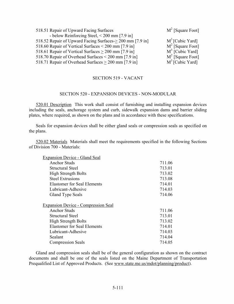
518.51 Repair of Upward Facing Surfaces M2 [Square Foot] - below Reinforcing Steel, < 200 mm [7.9 in] 518.52 Repair of Upward Facing Surfaces-> 200 mm [7.9 in] M3 [Cubic Yard] 518.60 Repair of Vertical Surfaces < 200 mm [7.9 in] M2 [Square Foot] 518.61 Repair of Vertical Surfaces > 200 mm [7.9 in] M3 [Cubic Yard] 518.70 Repair of Overhead Surfaces < 200 mm [7.9 in] M2 [Square Foot] 518.71 Repair of Overhead Surfaces > 200 mm [7.9 in] M3 [Cubic Yard]
SECTION 519 - VACANT
SECTION 520 - EXPANSION DEVICES - NON-MODULAR
520.01 Description This work shall consist of furnishing and installing expansion devices including the seals, anchorage system and curb, sidewalk expansion dams and barrier sliding plates, where required, as shown on the plans and in accordance with these specifications. Seals for expansion devices shall be either gland seals or compression seals as specified on the plans. 520.02 Materials Materials shall meet the requirements specified in the following Sections of Division 700 - Materials:
Expansion Device - Gland Seal Anchor Studs 711.06 Structural Steel 713.01
High Strength Bolts 713.02 Steel Extrusions 713.08 Elastomer for Seal Elements 714.01 Lubricant-Adhesive 714.03 Gland Type Seals 714.06
Expansion Device - Compression Seal Anchor Studs 711.06 Structural Steel 713.01 High Strength Bolts 713.02 Elastomer for Seal Elements 714.01 Lubricant-Adhesive 714.03 Sealant 714.04 Compression Seals 714.05 Gland and compression seals shall be of the general configuration as shown on the contract documents and shall be one of the seals listed on the Maine Department of Transportation Prequalified List of Approved Products. (See www.state.me.us/mdot/planning/product).
5-111

Acceptance of the materials for Expansion Devices will be based on a Materials Certification Letter as specified in Division 700 - Materials. 520.03 Fabrication All work shall conform to the applicable provisions of Section 504- Structural Steel. Seals shall be furnished and installed in one continuous length and splices will not be allowed except as specified hereafter. As received from the supplier of the seal, seals may contain one splice for each continuous length of 15 m [50 ft] or greater. Sections under 15 m [50 ft] long shall not have any splices. Splices at abrupt angular changes in horizontal alignment will be allowed. Splices in gland type seals shall be shop vulcanized by the seal supplier. Splices in compression seals may be either vulcanized or adhesive bonded. At abrupt angular changes in vertical alignment, the lower 75% of the depth of compression seals may be cut to allow short radius bends. 520.04 Protective Coating The expansion device, including the curb and sidewalk expansion dams and barrier sliding plates, shall be galvanized in accordance with the requirements for Protective Coating in Section 504 - Structural Steel. The galvanizing on the metal surfaces in direct contact with neoprene seals shall be lightly sandblasted to a dull gray appearance in order to promote a high strength bond between the seal and mating surface, and for smoothness for installation purposes. Alternately, this galvanized surface may be prepared to the manufacturer’s published recommendations for installation and bonding of seals. When specified on the contract plans, reinforcing steel shall be anchored into drilled holes. 520.05 Delivery Unless otherwise specified on the plans, expansion devices shall be shipped fully assembled and shall be installed as a unit. The unit shall be equipped with shipping and temperature adjustment devices approved by the Fabrication Engineer, and shall be preadjusted, in the shop, to the opening required at 7°C [45°F]. 520.06 Installation Expansion Devices shall be erected following placement of the structural deck slab. The devices shall be lowered in the blocked-out area of the deck slab, adjusted for the temperature as directed by the Resident, set to the proper height and fastened in place, in accordance with the Standard Details. Immediately following this, all shipping and temperature adjustment devices shall be removed and the blocked-out concrete for the slab and abutment backwall may be placed. Seal elements shall be installed in accordance with the manufacturer's recommendations, using equipment manufactured specifically for the installation of said element. The equipment shall not cause structural damage to either the seal or the joint armor and shall not twist, distort or cause other malformations in the installed seal element. Any perforation or tearing of a seal element due to installation procedures or construction activities will be cause for rejection of the installed seal element.
5-112
Immediately prior to the installation of the seal element, the metal contact surfaces of the joint armor shall be clean, dry, and free of oil, rust, paint, or foreign material. The contact surfaces of the seal element shall be cleaned with normal butyl-acetate, using clean rags or mops, immediately prior to application of the lubricant-adhesive or sealant. The lubricant adhesive or sealant shall be applied to the seal element and joint armor contact surfaces at the rate recommended by the manufacturer of the seal. The exposed ends of compression seals shall be sealed with appropriately shaped pieces of foam rubber, bonded in place with sealant as described in Section 714.04 - Sealant, or a bonding agent approved by the Resident. 520.07 Method of Measurement Expansion devices will be measured by each unit, complete in place and accepted. Each unit shall consist of one pair of matching elements, including anchorage system, seal, shipping and temperature adjustment devices, curb and sidewalk expansion dams and barrier sliding plates, as required. 520.08 Basis of Payment The accepted quantity of expansion devices will be paid for at the contract unit price each, which shall be full compensation for all materials including anchorage system, protective coating, equipment, labor and incidentals necessary for furnishing and installing the expansion devices and, if required, curb and sidewalk expansion dams and barrier sliding plates. Payment will be made under:
Pay Item Pay Unit
520.21 Expansion Device - Gland Seal Each 520.22 Expansion Device - Compression Seal Each
SECTION 521 - FINGER JOINT AND FABRIC TROUGH/FABRIC CURTAIN 521.01 Description This work shall consist of fabricating and installing finger joint expansion devices and fabric troughs or fabric curtains when required, including the anchorage system, curb and sidewalk expansion dams, barrier sliding plates as required, support components for fabric troughs or curtains when required, and any metal downspout(s) and/or chute(s) used to guide the discharge from the trough(s) when required, and all necessary materials and equipment required to complete the work as shown on the plans and in accordance with these specifications. 521.02 Materials - Finger Joints Plates requiring a non-skid surface shall conform to the requirements of ASTM A786/A786M, ASTM A36/A36M. Other plates shall conform to the requirements of ASTM A36/A36M or ASTM A572/A572M. Shapes shall conform to the requirements of ASTM A500, Grades A and B, or ASTM A992/A992M. Other weldable steels may be used with approval of the Fabrication Engineer. Anchor studs shall conform to the
5-113

requirements of Section 711.06 - Stud Shear Connectors, Anchor and Fasteners. Bolts shall conform to the requirements of AASHTO M169/M169M (ASTM A325/A325M). 521.03 General All work shall conform to the applicable provisions of Section 504 - Structural Steel. Completed expansion devices and any required support components for troughs or curtains, expansion dams, barrier sliding plates, downspouts and chutes shall be hot dipped galvanized to the requirements of AASHTO M111 (ASTM A123). Anchorage parts encased in concrete may be supplied in the ungalvanized condition. Each expansion device shall be shipped fully assembled, shall be installed as a unit, and shall be equipped with shipping and temperature adjustment devices approved by the Resident. When a project is built in stages, and if desired by the Contractor, the expansion device may be shipped in two or more sections, as approved by the Fabrication Engineer, with appropriate provisions for field splicing. 521.04 Materials Fabric Trough or Curtain The fabric for the trough or curtain shall be 3 mm to 5 mm [⅛ in to 3/16 in] in thickness and shall consist of a single layer of 415 g [14.6 oz] woven nylon fabric, or the equivalent in multiple layers of woven nylon fabric, laminated between two or more layers of neoprene rubber. The neoprene shall conform to the following requirements: Physical Properties: Grade (Duro) 60 Original Physical Properties 60 +/- 5 Hardness ASTM D2240 Tensile Strength, Minimum 13.8 MPa [2,000 psi] ASTM D412 Elongation at Break, Minimum Accelerated 300% Test to Determine Long Term Aging Characteristics Oven Aged - 70 Hours/100ºC [70 Hours/212ºF] ASTM D573 Hardness, Points Change, Maximum +15 Tensile Strength, Change, Maximum -15% Elongation at Break, Change, Maximum -40% Ozone - 1 PPM in Air by Volume 20% Strain No cracks 38 +/- 1ºC [100 +/- 2ºF] - ASTM D1149* 100 hours (*Samples shall be solvent wiped before test to remove any traces of surface impurities.) Compression Set - 22 Hours/100ºC [22 Hours/212ºF] ASTM D395 - Method B, 0/0 Maximum 35% ASTM D746 - Procedure B -40ºC [-40ºF] Brittleness at No Failure Fluid Resistance - ASTM D471 70 Hours/100ºC [70 Hours/212ºF] in ASTM Oil No. 3 Change in volume, Maximum +120%
5-114
Change in tensile strength, Maximum -70% Change in ultimate elongation, Maximum -55% The finished fabric shall have a minimum breaking strength of 120 N/mm [700 lb/in] when tested by ASTM Test Method D5034. The minimum breaking strength shall be determined on a sample taken transverse to the centerline of the trough, or a random sample taken from the curtain. When delivered to the job site, each separate length, roll or container shall be clearly tagged or marked with the manufacturer's name, trade mark and lot number. A lot is defined as that amount of fabric manufactured at one time from one batch of elastomer. A batch is defined as that amount of elastomer prepared and compounded at one time. The Contractor shall furnish a Materials Certification Letter for each lot in accordance with Division 700 - Materials. Not less than thirty days prior to the installation of the trough, a sample length of each lot of fabric, not less than 1 m [3 ft] long, shall be submitted to the Resident for testing. All samples shall be taken from the lot(s) to be furnished, shall be tagged for identification purposes and shall be furnished to the Resident free of cost. Approval of the material must be obtained before the material is incorporated in the work. 521.05 Fabrication The Contractor shall submit working drawings to the Fabrication Engineer for approval in accordance with Section 105.7 - Working Drawings. These drawings shall include, but not be limited to, the following information: The complete details of the method, materials and equipment proposed to be used in the installation operation. Such details shall give complete specifications and details of the elastomeric trough or curtain, and other data pertaining to the installation operation. Installation holes shall be cut round and cleanly with a sharp tool. Holes having jagged or roughly cut edges will be cause for rejection of the trough or curtain unit. 521.06 Construction of Fabric Trough Where a splice is required for stage construction, the upper section of the trough shall be fitted inside the lower section of the trough in such a manner that any water spillage through the splice shall be eliminated. 521.07 Method of Measurement Expansion Device - Finger Joint will be measured by each unit, complete in place and accepted. Each unit shall consist of one pair of matching devices including anchorage system, curb and sidewalk expansion dams, barrier sliding plates as required, and if shown on the plans, trough or curtain components, downspouts and chutes. Fabric trough or curtain for finger joint will be measured for payment by each unit complete in place and accepted. 521.08 Basis of Payment The accepted quantity of Expansion Device - Finger Joint will be paid for at the contract unit price each, which payment shall be full compensation for all materials including anchorage system, curb and sidewalk expansion dams, barrier sliding plates, trough or curtain support systems, downspouts and chutes, galvanizing, equipment, labor and
5-115
incidentals necessary for furnishing and installing the expansion devices and expansion dams. The accepted quantity of fabric trough or curtain for finger joint will be paid for at the contract price each, complete in place and accepted, which price shall include all materials, equipment, tools and labor incidentals thereto. Payment will be made under:
Pay Item Pay Unit
521.23 Expansion Device - Finger Joint Each 521.32 Fabric Trough for Finger Joint Each 521.33 Fabric Curtain for Finger Joint Each
SECTION 522 - EXPANSION DEVICES - MODULAR 522.011 Description This work shall consist of furnishing and installing shop fabricated modular expansion devices. This shall include, but not be limited to, neoprene seal elements, steel transverse dividers and end channels, support bars and bearings, anchorages, sidewalk, median and curb expansion dams and barrier slide plates, all as specified herein or specified in the Contract documents. 522.012 Materials Materials shall meet the requirements specified in the following Sections of Division 700 - Materials: Stud Shear Connectors, Anchor and Fasteners 711.06 Structural Steel 713.01 High Strength Bolts 713.02 Steel Extrusions 713.08 Lubricant Adhesives 714.03 Gland Type Seals 714.06 All steel divider bars, end channels and support bars shall conform to the requirements of ASTM A572/A572M Grade 345 [Grade 50] Steel. Other steel plates shall conform to the requirements of ASTM A36/A36M or ASTM A572/A572M. Shapes shall conform to the requirements of ASTM A500, Grades A and B, or ASTM A992/A992M. Other weldable steels may be used with the approval of the Fabrication Engineer. The entire assembly, unless otherwise indicated on the contract plans, shall be hot dip galvanized in conformance with AASHTO M111 (ASTM A123). All miscellaneous materials such as stainless steel sliding surfaces, bearings, etc. shall be as recommended by the manufacturer, and as approved by the Fabrication Engineer. The manufacturer shall submit full information on material specifications and dimensional data for approval. 522.013 Design The modular expansion devices shall incorporate divider bars, end channels, divider bar supports, seals, a system to maintain the seals at a substantially equal spacing at all times, and joint armor incorporating a support system for the divider bar supports
5-116

and an anchoring system for fixing the expansion device to the supporting concrete. The expansion devices shall be capable of accommodating the movements specified on the design drawings. The system maintaining the seal spacing shall be subject to prior approval by the Fabrication Engineer and shall be a design that does not employ a rigid scissors type mechanical system. The seal spacing system shall at all times exert a positive control force, and shall have a certain amount of flexibility to absorb shock loads such as snowplow impacts. The sealing elements shall be gland type seals, and shall be fabricated with lugs or other protrusions designed to have a positive interlocking action with the divider bars. Sealing elements that are continuous over the full width of the joint, and require a clamping element to fix the sealing element to the top surface of the divider bar(s), will not be accepted. The minimum joint opening between adjacent divider bars shall be 12 mm [½ in], and the maximum joint opening shall be 89 mm [3½ in]. The divider bars and end channels shall be extruded or rolled shapes, designed to positively interlock with the sealing elements, and capable of sustaining all vertical and horizontal loads imposed by the traffic. The divider bar supports shall be supported on the joint armor in a manner incorporating sufficient flexibility to absorb vertical shock loads. The divider bars, divider bar supports and associated bearings, hardware, etc. shall be designed in accordance with the AASHTO LRFD Bridge Design Specifications. The manufacturer shall submit computations and data to verify appropriate load carrying capacity and said computations shall show conformance to all applicable requirements, including fatigue criteria, of the AASHTO LRFD Bridge Construction Specifications. 522.014 Fabrication The expansion joints shall be shop assembled in accordance with the manufacturer's recommendations and in conformance with the details shown in the Contract documents and in these specifications. All work shall be in accordance with the applicable provisions of Section 504 - Structural Steel. Twenty-five percent of full penetration welds shall be ultrasonic tested. Twenty-five percent of fillet welds and partial penetration welds shall be inspected by magnetic particle. Acceptance criteria shall be in accordance with the AWS D1.5 Bridge Welding Code. All shop welding shall be completed to the greatest extent possible before the steel is galvanized. Any welds to be made after the steel is galvanized shall be identified on the Shop Drawings. Steel surfaces welded subsequent to galvanizing shall be repaired to the requirements of ASTM A780 and Annexes A1, A2 or A3. The dry film thickness shall be within the range of 75 µm to 120 µm [3 mils to 5 mils]. Damaged areas of the galvanizing shall be similarly treated. The galvanizing on the metal surfaces in direct contact with the neoprene seals shall be lightly sandblasted to a dull gray appearance to provide a high strength bond between the seal and mating metal surfaces, and to provide an appropriate surface smoothness for installation.
5-117

Alternately, this galvanized surface may be prepared to the published manufacturer’s recommendations for installation and bonding of the seals. Seal elements shall be furnished and shop installed in one continuous length. Splices in seals will be permitted at abrupt changes in horizontal alignment. Abutting surfaces of splices shall be shop-vulcanized together.
The Contractor shall submit computations, Shop Drawings, erection drawings, and other Working Drawings in accordance with Section 105.7 - Working Drawings.
The fabricated expansion device shall be preset by the manufacturer, before shipment, to the dimensions for 7°C [45°F]. Hardware for leveling, shipping and adjusting the device shall be supplied as part of the assembled expansion device. Final width adjustments of the prefabricated expansion device shall be made at the direction of the Resident, in the field, prior to the final concrete placement. 522.015 Delivery Modular expansion devices shall be delivered to the job site in one unit, fully assembled. No field joints will be allowed, unless shown on the design drawings or approved by the Fabrication Engineer before shop fabrication. 522.016 Installation Following completion of the structural deck slab, the expansion devices shall be installed in the blocked out portion of the slab and abutment backwall. Following final adjustment, the device shall be permanently fixed in place, all shipping and adjustment devices shall be removed, surfaces shall be repaired as specified in Section 522.014 - Fabrication, and concrete shall be placed to complete the deck slab and backwall to the lines and grades shown on the design drawings. 522.017 Method of Measurement Modular Expansion Devices will be measured by each unit, complete in place and accepted. Each unit shall consist of a modular expansion device, including anchorage system, seals, shipping and temperature adjustment devices, curb, sidewalk and median expansion dams and barrier sliding plates, as required. 522.018 Basis of Payment The accepted quantity of Modular Expansion Devices will be paid for at the contract unit price each, which payment shall be full compensation for all materials, equipment, labor and incidentals necessary for furnishing and installing the expansion devices, curb, sidewalk and median expansion dams and barrier sliding plates, as required. Payment will be made under:
Pay Item Pay Unit
522.06 Modular Expansion Devices Each
5-118
SECTION 523 - BEARINGS
523.01 Description This work shall consist of designing, furnishing, testing and installing bearings in accordance with this Specification, and in conformance with the details shown on the plans.
523.02 Materials
Elastomer 711.11 Stainless Steel 711.12 PTFE 711.13
Structural Steel 713.01 Preformed Pads 713.03
Miscellaneous materials, caulking or lubricant shall be as recommended by the manufacturer of the bearings.
523.03 Submittals The Contractor shall prepare shop detail, erection and other necessary
working drawings in accordance with Section 105.7. The drawings will be reviewed and approved in accordance with the applicable requirements of Section 105.7. Changes and revisions to the approved working drawings shall require further approval by the Fabrication Engineer.
523.04 General Requirements Requirements for the type of bearing furnished are as
follows:
Steel Bearings Sections 523.10 thru 523.19 Elastomeric Bearings Sections 523.20 thru 523.29
Pot or Disc Bearings Sections 523.30 thru 523.39 Spherical Bearings Sections 523.40 thru 523.49
523.06 Fabrication Tolerances Fabrication tolerances for all bearings shall comply with Section 18.1 of AASHTO, LRFD Bridge Construction Specifications (Table 18.1.4.2-1) unless otherwise noted on the plans or in this Section 523 - Bearings.
523.05 Fabrication Steel fabrication work, for all types of bearings, shall comply with
Section 504 - Structural Steel. 523.07 Inspection The Contractor shall notify the Fabrication Engineer at least 10 days in
advance of the start of fabrication so that inspection of the work can be provided by the Department. All work will be subject to inspection by the Fabrication Engineer.
Quality Control (Q.C.) is the responsibility of the Contractor. The Quality Control Inspector
(Q.C.I.) shall inspect all aspects of the work and shall supervise all testing. The Q.C.I. shall record measurements and test results in a Job Control Record (JCR). The Q.C.I. shall reject materials and workmanship that do not meet contract requirements. The Contractor may
5-119

perform testing in addition to the minimum required. The results of all measurements and testing shall be made available to the Quality Assurance Inspector (Q.A.I.).
Quality Assurance (Q.A.) is the prerogative of the Fabrication Engineer. The Q.A.I. will
ensure that the Contractor’s Q.C. is performing properly, verify documentation, periodically inspect workmanship and witness testing. Q.A. testing deemed necessary by the Fabrication Engineer in addition to the minimum testing requirements shall be scheduled to minimize interference with the production schedule.
523.08 Certification The Contractor shall furnish a materials certification letter in
accordance with Division 700.
523.09 Installation Bearings Bearings shall be placed upon bridge seats that are properly finished. Bridge seat elevations shall be within + 6 mm [¼ in] of the elevation shown on the plans and the differential elevation between any tow adjacent bearing areas shall not exceed + 10 mm [⅜ in] than that shown on the plans. When the bearings are to be set directly on the concrete bridge seats, as indicated on the plans, the bridge seats shall be dressed 25 mm [1 in] larger all around than the bottom member of the bearing and to the exact elevations shown on the plans or as determined by the Resident. If dressed areas are lower than the surface of the surrounding bridge seat, a channel 50 mm [2 in] wide and with a minimum slope of 4 percent, shall be cut to the edge of the bridge seat for drainage. Masonry plates shall be set level in their exact position and shall have a full and even bearing upon the masonry. They shall be placed on a preformed pad, the same size and shape as the masonry plate with holes to match the masonry plate. 523.09.1 Anchor Rods The contractor shall drill the holes and set the anchor rods with an Anchoring Material from the Department’s Pre-qualified List. The anchor rods shall be accurately set with an approved two part high-strength epoxy mortar. The epoxy mortar shall completely fill the holes. Anchor bolts shall be capable of developing unconfined pullout strength of 120 kN and 280 kN (30 kips and 70 kips) for M24 and M36 (1 in and 1 ½ in) anchor bolts respectively. The Department reserves the right to perform in-place pullout tests. Bolts failing to meet the pullout strength requirements shall be replaced at the Contractor’s expense. 523.09.2 Grout Pads When the bearings are to be set on a grout pad, the grout shall be composed of one part of Portland cement, Type I or II, to two parts fine aggregate by weight with non-shrink admixture, approved by the resident, well mixed with sufficient water to produce proper consistency. The grout shall have a minimum compressive strength of 27.5 MPa [4000 psi] at 28 days. A sufficient quantity of the grout materials, including admixtures, and the design composition shall be submitted to the Resident for testing 60 days prior to placement.
5-120

The grout shall be well bonded to the adjacent concrete and shall be placed under pressure to ensure that all anchor holes and the entire area under the masonry plate is free of voids. 523.09.3 Sliding Surfaces The sliding surfaces of bearings shall be installed level. Special care shall be exercised at all times to ensure protection of the stainless steel and the PTFE surfaces from coming in contact with any foreign matter. At no time shall any forms, debris, or other material interfere with the free action of the bearing assemblies. When bronze or copper-alloy bearing and expansion plates are used, the sliding surfaces or the steel in contact with the bearing and expansion plates shall be recoated immediately prior to installation with a lubricant recommended by the manufacturer of the bronze or copper-alloy plates. 523.09.4 Final Adjustment Bearings shall not be welded in place until the deck is in place and dead load deflection(s) of the superstructure has occurred. Final adjustment of the bearings for temperature shall be made after dead load deflection of the superstructure has taken place. Welding of the sole plate to the flange shall be done, only after all adjustments have been made. Sliding expansion bearings shall be set so that slotted holes in the sole plate will be centered on the anchor bolts, and rocker bearing assemblies shall be set so as to be plumb at 7ºC [45º F]. When determining temperature adjustments for bearings, the difference between the steel temperature (not the ambient temperature) and 7ºC [45º F] shall be used. Nuts on anchor rods shall be brought in contact with the masonry plate or sole plate as shown on the plans. Threads on anchor rods shall be upset with a punch to prevent easy removal of the nuts. When anchor rods extend through slotted holes in a sole place, the lower of double nuts shall be left loose, bring to contact and loosen approximately ¼ turn, to allow movement of the sole plate.
STEEL BEARINGS
523.10 Steel Bearings Structural steel bearings, pedestal type, rocker type, sliding plate type shall be fabricated in accordance with the dimensions and finishes shown on the plans, Standard Details and the requirements of Section 504 - Structural Steel.
523.11 Materials Materials shall conform to Section 523.02 - Materials.
ELASTOMERIC BEARINGS
523.20 Description Two types of bearings are applicable for the following Sections; 1) Laminated Elastomeric Bearings consist of layers of elastomer laminated to steel plates and 2) Plain Elastomeric Bearings shall consist of a single layer of elastomer.
523.21 Materials Materials shall conform to Section 523.02 - Materials.
5-121

If the elastomer material is specified by its shear modulus on the contract drawings, the measured shear modulus value shall lie within the specified range. When the elastomer material is specified by shear modulus, the Contractor shall supply a consistent value of hardness for the purposes of defining limits for the tests of Table A and B in Section 711.11.
Shear modulus tests shall be carried out using the apparatus and procedure described in
Annex A of the ASTM D4014 specifications. Flash tolerance, finish, and appearance shall meet the requirements of the latest edition of
the Rubber Handbook as published by the Rubber Manufacturers Association, Inc., RMA F3 and T.063 for molded bearings and RMA F2 for extruded bearings.
523.22 Fabrication All components of Laminated Elastomeric Bearings shall be molded as
an integral unit. Plain Elastomeric Bearings may be molded individually, cut from previously molded slabs, or extruded and cut to length. Cut edges shall have an ANSI 5 µm [250 mils] finish. Steel laminates shall be abrasive blast cleaned to an SSPC SP-6 and protected from contamination.
523.23 Testing The following testing shall be performed prior to delivery of the bearings:
1. Ambient Temperature Tests on the Elastomer (This test is required for each elastomer
formulation.) The bond to the reinforcement shall develop a minimum peel strength of 6.9 N/mm [39.4
lb/in]. Peel strength tests shall be performed by ASTM D429, Method B. The shear modulus of the material shall be tested at 23oC [74oF] using the apparatus and procedure described in Annex A of the ASTM Specifications. In lieu of performing a shear modulus test for each batch of material, the manufacturer may elect to provide certificates from tests performed, on identical formulations, within the preceding year.
2. Low-Temperature Test on the Elastomer (This test is required for each elastomer
formulation.) Low-temperature tests shall be performed in accordance with the requirements of
Section 711.11; the compound shall satisfy all criteria for its grade. The manufacturer may choose to provide certificates from low-temperature crystallization tests performed, on identical material, within the last year for Grade 3 to Grade 5 material.
3. Visual Inspection of the Finished Bearing Each bearing shall be inspected for
compliance with dimensional tolerances and for overall quality of manufacture. In steel reinforced bearings, the edges of the steel shall be protected everywhere from corrosion.
4. Short-Duration Compression Tests on Bearings Each bearing shall be loaded in
compression to 150% of the Bearing Design Load. The load shall be maintained for 5 minutes and released. The same load shall be reapplied and maintained for a second period
5-122
of 5 minutes. The bearing shall be examined visually during the second loading. If the load drops below the required value during either application, the test shall be performed again.
The bearing shall be rejected if:
The bulging pattern suggests laminate parallelism outside of the specified tolerance A layer thickness is outside the specified tolerances, A poor laminate bond exists, or Three or more separate surface cracks greater than 2 mm [0.079 in] wide and 2 mm [0.079 in] deep exists.
5. Long-Duration Compression Tests on Bearings (This test is required on 10% of each type and size of bearing furnished.)
The long-term compression test shall be performed as specified in section 4 above,
"Short-Duration Compression Tests on Bearings", except that the second load shall be maintained for 15 hours. The bearing shall be visually examined at the end of the tests while still under the load. If any patterns or cracks specified in section 4 above occurs, all bearings from that lot shall be rejected, unless the manufacture elects to test each bearing of the lot. If the additional testing does not reveal any rejectable defects as noted in 4 above, the bearings will be accepted. 6. Shear Modulus Tests on Material from Bearings (This test is required for each
elastomer formulation.)
The shear modulus of the elastomer in the finished bearing shall be evaluated by testing a specimen cut from it using the apparatus and procedure described in Annex A of the ASTM specifications, amended where necessary in Tables A or B; or at the discretion of the Fabrication Engineer, a comparable nondestructive stiffness test may be conducted on a pair of finished bearings. The shear modulus shall fall within the specified range. If the test is conducted on the finished bearings, the material shear modulus shall be computed from the measured shear stiffness of the bearings, taking due account of the influence on shear stiffness of bearing geometry and compressive load.
Shear modulus tests performed on a sample of the same material as was used to
fabricate the bearings will be acceptable. Shear modulus testing shall be performed using the apparatus and procedure described in ASTM D4014, Annex A.
POT or DISC BEARINGS
523.30 Design Pot or Disc bearings shall be designed for the loads and movements given on
the plans. Configurations and dimensions other than those given on the plans may be accepted subject to the approval of the Fabrication Engineer. Design calculations to substantiate all the requirements stated in this specification shall be submitted as part of the shop drawings.
5-123

Except where indicated on the plans, the design shall also include the connections between the bearings and the superstructure, and the bearings and the substructure, along with adequate provisions for hold-downs equal to the tensile strength of the anchor bolts.
The bearings shall be designed to accommodate a rotation of not less than 0.015 radians. The static coefficient of friction between the polytetrafluoroethylene (PTFE) and the
stainless steel surface, for each size and type of bearing, shall not exceed 0.04 at the average unit bearing pressure for the minimum vertical load indicated on the plans.
The bearings shall be designed for a horizontal force at least equal to 10% of the vertical
capacity of the bearing. No more than two bearings, with guide bars, per bearing line, shall be considered to be
carrying the total maximum lateral horizontal load as indicated on the plans. Bearing friction shall not be considered when the horizontal load capacity of guided or fixed
bearings is calculated.
The elastomeric discs shall be designed to meet the following:
1. The minimum thickness shall be 1/15 of the diameter. 2. The average unit pressure shall be 24.1 MPa [3500 psi], -0%, +10%, for the
maximum vertical load indicated on the plans. 3. The average unit pressure shall not be less than 4.8 MPa [700 psi] for the minimum
vertical load indicated on the plans. 4. When utilizing flat brass sealing rings, the upper edge of the discs shall be recessed to
receive the brass rings. 5. A PTFE sheet, filled or unfilled, 1.6 mm [1/16 in] minimum thickness and the same
diameter as the design diameter of the disc, shall be placed below the discs.
The pot shall be designed to meet the following:
1. The depth of the cavity shall be equal to or greater than: twice the design rotation plus 2.5 mm [0.1 in] plus the thickness of the elastomeric disc and the PTFE sheet.
2. The inside diameter shall be the same as the design diameter of the elastomeric disc. 3. The pot shall be mounted, to provide a tight fit, in a 3 mm [⅛ in] minimum depth
recess in the steel masonry plate or distribution plate and shall be capable of being removed for inspection and repairs.
5-124

The piston shall be designed to meet the following:
1. The outside diameter shall be 0.76 mm [0.03 in] less than the inside diameter of the pot.
2. The minimum thickness shall be not less than 0.08 times the design diameter. 3. When utilizing round brass sealing rings, the lower outside edge shall be beveled to
accept and retain the brass ring and to permit full design rotation. 4. Laterally restrained pot bearings shall have a keyway in the sole plate. The top
surface of the piston shall have a keyway slot and a cold finished steel guide bar press fitted into it and welded at the ends.
5. A PTFE sheet, filled or unfilled, 1.6 mm [1/16 in] minimum thickness and the same
diameter as the bottom surface of the piston, shall be bonded to the bottom surface of the piston.
The elastomer sealing rings shall be brass and shall be designed to meet the following:
1. Flat brass sealing rings, if utilized, shall:
a. Have a width of 10 mm [⅜ in] minimum with bearings up to a 4450 kN [1000 kip] capacity and a 13 mm [½ in] width with bearings over a 4450 kN [1000 kip] capacity.
b. Have a minimum thickness of 1.3 mm [.050 in]. c. Have two rings with a bearing capacity up to 4450 kN [1000 kip], three rings with
a bearing capacity over 4450 kN [1000 kip], but less than 13,500 kN [3000 kip], and four rings with a bearing capacity of over 13,500 kN [3000 kip].
d. Have the ends cut at 45° with a minimum gap in the installed position of 1.27 mm
[.050 in] and shall fit the inside diameter of the pot snugly. e. Have the ring gaps staggered 180° apart.
2. Round brass sealing rings, if utilized, shall:
a. Be of one piece with the ends brazed to make a solid ring. b. Have the outside of the ring fit snug in the inside diameter of the pot.
The PTFE sliding surface shall be designed to meet the following:
5-125
1. The average unit pressure shall be 24.1 MPa [3500 psi], -5%, +0%, for the maximum vertical load indicated on the plans.
2. Unfilled PTFE shall have a minimum thickness of 3.2 mm [⅛ in] with half of its
thickness recessed into the piston. 3. Filled PTFE shall be a minimum of 1.6 mm [1/16 in] thick and shall be bonded to the
surface of the piston and to the guide bar. 4. The maximum thickness of the PTFE, filled or unfilled, shall be 2.4 mm [3/32 in],
except, if recessed it shall be 4.8 mm [3/16 in].
The stainless steel sliding surface shall be designed to meet the following:
1. The stainless steel shall cover the PTFE in all operating positions such that the stainless steel will have a minimum of 25 mm [1 in] edge clearance beyond the PTFE.
2. The thickness shall be not less than 1.02 mm [.040 in] nor greater than 2.29 mm [.090
in]. 3. When a center guided key is utilized, a recess shall be machined in the sole plate and
the vertical sliding surfaces of the recess shall be covered with stainless steel.
The guide bars shall be designed to meet the following:
1. The guide bars shall be designed for the maximum horizontal load, as indicated on the plans, but not less than 10% of the vertical capacity of the bearing.
2. The guided member shall be within the guide bars at all operating positions. 3. The overall width of the guide bar and the PTFE sliding surfaces shall be 3.2 mm [⅛
in] less than the clear width of the keyway in the guided member. 4. A PTFE sheet, 1.6 mm [1/16 in] minimum thickness shall be bonded to the sliding
contact surfaces of the guide bars. The sheets shall be filled PTFE.
523.31 Materials Materials shall conform to Section 523.02 - Materials and the following: Sealing rings shall be brass. Flat rings shall conform to the requirements of ASTM B36,
half hard. Round sealing rings shall conform to the requirements of Federal Specification QQB626, Composition 22, half hard.
Elastomer shall have a Shore A hardness of 50 or 60 DURO. 523.32 Fabrication Bonding of PTFE sheets to the piston shall be under factory-controlled
conditions and in accordance with written instructions of the manufacturer of the adhesive.
5-126

After completion of the bonding operation, the PTFE surface shall be smooth and free from bubbles. PTFE surfaces shall not be polished, but shall be wiped clean using a solvent appropriate for the material.
The stainless steel sliding surfaces shall be seal welded around the entire perimeter. The
surfaces shall be smooth and flat and the back shall remain in contact with the sole plate. Pots shall be machined from a solid plate or fabricated by welding a cut shape to a plate.
Fabricated pots shall be 100% ultrasonically tested at the inside weld and magnetic particle tested at the exterior weld.
The elastomeric discs shall be manufactured from no more than three pieces. Each bearing shall be assembled at the plant and following assembly, shall be sealed at the
joint between the piston and the pot with a continuous 6 mm [¼ in] bead of a flexible silicone rubber sealing compound approved by the Fabrication Engineer.
Each bearing shall have permanent match marks to indicate the neutral 7°C [45°F] position
of the bearing. Each bearing shall also be marked for identification by die stamping on all steel parts (edge of sole plate, piston, masonry plate, and top edge of pot).
Each bearing shall be shipped and stored in moisture-proof and dust-proof covers until they
are to be erected. 523.33 Fabrication Tolerances Tolerances shall comply with Section 523.04 - General
Requirements, and as noted below.
Brass sealing rings shall have finished surfaces of less than 1.6 µm [63 mils] (ANSI B 46.1).
523.34 Protective Coating All structural steel, except surfaces bonded to PTFE and stainless steel surfaces, shall be zinc metalized in accordance with Section 506 - Protective Coating. Thickness shall be 0.20 mm [8 mils] on exterior surfaces and 0.05 mm [2 mils] on interior surfaces.
523.35 Testing and Certification The manufacturer of the pot bearings shall furnish test
facilities for testing and inspection of the completed bearings in their plant or at an independent test facility approved by the Fabrication Engineer. The Fabrication Engineer or their authorized representative shall be allowed free access to the manufacturer's plant and test facility. The Fabrication Engineer will select two completed bearings for testing. The test shall be arranged so that the static coefficient of friction on the first movement can be determined. The test shall first be conducted at an average bearing pressure of 24 MPa [3500 psi] on the PTFE surface with the test load applied continuously for not less than 12 hours nor more than 14 hours prior to measuring the friction. The first movement static coefficient of friction shall then be determined. The above test shall then be repeated for the minimum vertical load indicated on the plans for the bearings selected. The results shall not exceed that specified for the design.
5-127
A proof load test shall also be performed on each test bearing by applying a load equal to 150% of the maximum vertical load indicated on the plans for the bearings selected for a period of one hour. The test bearings shall show no sign of failure or other defects while under load or subsequently upon disassembly and inspection.
Before testing, the testing equipment and procedure shall be reviewed by the Fabrication
Engineer. 523.40 thru 523.49 Reserved - Spherical Bearings 523.50 Method of Measurement Bearings will be measured for payment by each unit, tested
and accepted. Bearing installation will be measured for payment by each unit in place and accepted.
523.51 Basis of Payment Bearings will be paid for at the contract unit price each, which
price shall be full compensation for the design, fabrication, testing, and delivery. Bearing installation will be paid for at the contract unit price each which price shall be full compensation for installation, including all materials, equipment, labor and incidentals necessary for installing the bearings in accordance with the plans and this Specification. Removal of the existing bearings if present, including all materials, equipment, labor and incidentals necessary for jacking the superstructure, removal of the existing bearings and preparation of the bridge seat in accordance with the plans and this Specification shall be considered incidental to bearing installation.
Payment will be made under:
Pay Item Pay Unit
523.52 Bearing Installation Each 523.5301 Steel Bearings, Fixed, Sliding Plate Each 523.5302 Steel Bearings, Expansion, Sliding Plate Each 523.5303 Steel Bearings, Fixed, Rocker Each 523.5304 Steel Bearings, Expansion, Rocker Each 523.5401 Laminated Elastomeric Bearings, Fixed Each 523.5402 Laminated Elastomeric Bearings, Expansion Each 523.5403 Plain Elastomeric Bearings Each 523.5551 Pot or Disc Bearings, Fixed Each 523.5552 Pot or Disc Bearings, Expansion Each 523.5601 Spherical Bearings Each
SECTION 524 - TEMPORARY STRUCTURAL SUPPORTS 524.01 Description This work shall consist of the designing, fabricating, erecting, maintaining, and dismantling of temporary structural support(s) as called for on the contract
5-128

plans, all in conformity with these specifications. Temporary structural supports proposed by the Contractor to facilitate the work shall also conform to these specifications. 524.02 Materials Materials used may be either sawn timber or steel, or a combination of both, at the Contractor's option, and, whether new or used, shall be sound and of adequate cross section for the intended loads. Blocking needed below the temporary supports to accommodate differences in elevation, and/or pads required to distribute loads to the soil may additionally incorporate plain and reinforced concrete. 524.03 Design Temporary structural support(s) shall be designed to support all vertical loading including live load and impact, differential settlement forces, horizontal and longitudinal forces, and shall account for any temporary unbalanced loading due to jacking forces and other loading during load transfer. Sufficient redundancy shall be designed into the support structure so that failure of one member will not cause the collapse of the entire system and the supported structure. Temporary support(s) shall be designed by a registered Professional Engineer and all plans, computations, and working drawings shall be signed by that Engineer, and shall be submitted to the Resident for approval. Temporary supports, which are adjacent to traveled ways or which support structures carrying traffic, shall additionally be designed to resist any vibration or impact forces due to traffic and shall incorporate sufficient protection against impact by errant vehicles. 524.04 Erection and Removal The erection of temporary support(s) shall be in strict conformance with the approved design and details and shall use only the materials approved for use. No loads shall be placed on the temporary support(s) without the prior approval of the Resident.
No loads shall be placed on temporary supports which are adjacent to traveled ways or which support structures carrying traffic unless the Engineer responsible for the design has certified to the Resident that the system was erected in conformance with the approved plans and design details.
The approval by the Resident of all or part of temporary support(s) shall not be construed as in any way relieving the Contractor of their responsibility and the work shall be entirely at the Contractor's risk. Upon completing the work requiring the use of the temporary structural supports, they shall be removed and the area under and around the temporary structural supports shall be restored to its original condition. 524.28 Method of Measurement Temporary structural supports will be measured as the number of individual units called for on the plans, satisfactorily designed, erected, and dismantled. Temporary supports used by the Contractor for their convenience will not be measured for payment. The removal and reinstallation of existing highway appurtenances (e.g. guardrails, sign supports, etc.) to facilitate the erection of temporary supports will not be measured for payment, but will be considered incidental to the work under this specification.
5-129
524.29 Basis of Payment Temporary structural supports will be paid for at the contract unit price each which price shall be full compensation for all materials, equipment, labor and incidentals necessary for the design, erection, maintenance, and dismantling of such supports in accordance with these specifications.
Pay Item Pay Unit
524.30 Temporary Structural Support Each
SECTION 525 - GRANITE MASONRY 525.01 Description This work shall consist of furnishing and placing granite pier facing in accordance with these specifications and as shown on the plans. 525.02 Materials The granite shall be obtained from an approved quarry and be free from materials which, by weathering, would cause discoloration or deterioration. The granite for the entire Project shall be uniform in color and free from seams, cracks and other structural defects. Caulking of joints shall be accomplished with a two-component, epoxy-resin system designed for the intended use. A quartzite aggregate shall be added in accordance with the manufacturer's recommendations. The material shall be moisture insensitive, of low modulus of elasticity, and of a gel-like non-sag viscosity. Color shall be gray. The materials shall be subject to the approval of the Resident. Anchors shall be of either ASTM A36/A36M steel, galvanized in accordance with AASHTO M111 (ASTM A123), or ASTM A276 Type 304 stainless steel, 19 mm [¾ in] diameter, as indicated on the plans. Other types of anchors may be used with prior approval of the Resident. Joint mortar shall comply with Section 705.02 - Joint Mortar, except it shall contain an additive to insure water-tightness. The additive shall not contain a retarding agent or hydrated lime and shall be approved by the Resident. 525.03 General Granite masonry shall have all stones dressed and cut to exact dimensions and laid up in joint mortar, with joints 12.5 mm +/- 3 mm [½ in +/- ⅛ in] in thickness. A complete setting plan shall be submitted for approval before ordering any stone. The arrangement and the length of the stones shall be as approved by the Resident. 525.04 Stones The finish on exposed surfaces of the stones shall be free from tool marks. Irregular projections shall be limited to a maximum of 75 mm [3 in] for any one stone measured from the pitch line. Irregular depressions shall be limited to a maximum of 25 mm [1 in] for any one stone measured from the pitch line.
5-130
Stones shall have their edges pitched to a true line with tops and bottom parallel and cut to lie on their natural beds. The top and bottom beds shall be the full size of the stone, and hollow beds shall not be permitted. The beds of stone shall be sawn or fine finished, full depth. The vertical face joints shall be sawn or fine finished for a depth of not less than 102 mm [4 in], with the balance not to fall away more than 102 mm [4 in]. The top layer of granite shall have a 38 mm [1½ in] wide chisel draft line along the top face adjacent to concrete. All stones shall be so finished that no holes or portions of holes shall show on surfaces that will be exposed in the finished work. The depth of the stone shall be not less than 203 mm [8 in] and not more than 305 mm [12 in] measured from the back face of the stone to the pitch line. The Contractor shall use extreme care when placing the concrete within the boundaries of the stone facing to avoid causing air pockets due to overhanging stones. Stone heights shall be a minimum of 380 mm [15 in]. 525.05 Anchors Holes for anchors shall be drilled in the stones before they are placed. There shall be a minimum of 2 anchors at a maximum spacing of 1219 mm [48 in] in the top and bottom beds of each piece and grooves shall be cut from the anchor holes to the back of the stones. Stones greater than 1219 mm [48 in] in height shall have additional anchors located in the back face of the pieces such that there will be a maximum spacing, both vertical and horizontal, of 1219 mm [48 in] between anchors. Anchors in the top and bottom beds of each stone shall be located such that an anchor will be not greater than 457 mm [18 in] from each end of the piece. Anchors in the back face of each stone shall be located such that an anchor will be not greater than 457 mm [18 in] from each end of the piece. 525.06 Mortar Joint mortar shall be machine mixed for not less than 1½ minutes after all ingredients are in the mixer. Mortar shall be used within 30 minutes after mixing and the retempering of mortar will not be permitted. The mixing and placing of mortar shall be discontinued when the atmospheric temperature is below 5°C [40°F] in the shade and dropping and shall not be resumed until the atmospheric temperature is as high as 2°C [35°F] in the shade and rising, unless otherwise authorized by the Resident. 525.07 Setting Stones Stones shall be thoroughly cleaned before being set, and the bed to receive it shall be well cleaned. The thickness of all joints and beds shall be uniform throughout. Spalls shall not be used as pinners in mortar beds or joints. When any stone is disturbed or mortar joint broken, the stone shall be taken up, and after all mortar has been cleaned from the stone, bed and joints, the stone shall be reset in fresh mortar. All stones shall be well bedded with the face joints properly raked before the mortar has set.
5-131
The masonry shall be kept wet during the pointing, and in hot or dry weather shall be protected from the sun and kept wet for a period of 3 days after completion of setting, unless otherwise permitted or directed. Face surfaces of stone shall not be smeared with mortar and after pointing has been completed and set, the masonry shall be thoroughly cleaned as directed. Stones shall not be set when the stones contain frost or during freezing weather, unless otherwise permitted. Concrete backing shall be of the class shown on the Plans. The concrete shall be so worked and compacted that all spaces around stones are completely filled and an adequate bond with the stone is secured. Construction joints in the concrete, required by intermittent placing, shall be located not less than 152 mm [6 in] below the top bed of any course of the stone facing. The stones shall be secured and the concrete so placed, as approved by the Resident, to prevent movement of the stones during placement of the concrete. 525.08 Joints All joints shall be raked 38 mm [1½ in] deep and caulked with an approved two-component epoxy-resin system. All caulking shall be done in such a manner as to produce a tight, durable and impervious seal at all joints. All caulking shall be accomplished as soon as possible to avoid exposure at joints to salt water. The two-component epoxy-resin system shall be proportioned, mixed, and applied in accordance with the manufacturer's recommendations. The joint below the bottom layer of granite shall be 25 mm +/- 12.5 mm [1 in +/- ½ in] in thickness. 525.09 Method of Measurement Granite masonry will be measured for payment by the number of square meters [square feet] of exposed granite masonry, including joints, in the completed work and measured from the pitch lines as shown on the plans. 525.10 Basis of Payment Granite masonry will be paid for at the contract unit price per square meter [square foot] complete in place and accepted. This price shall include all materials, labor and incidentals necessary to complete the work. The cost of the anchors, completed and in place, shall be included in the contract unit price of this item. Payment will be made under:
Pay Item Pay Unit
525.30 Granite Masonry square meter [Square Foot]
SECTION 526 - CONCRETE BARRIER
526.01 Description This work shall consist of the furnishing, constructing, erecting, setting,
resetting, and removal of concrete barrier and associated elements in accordance with these specifications and the lines and grades shown on the plans or established by the Resident.
5-132
The types of concrete barrier are designated as follows:
Temporary Concrete Barrier Type I Double faced removable concrete barrier of the shape shown on the plans.
Permanent Concrete Barrier Type II Double face barrier of a shape shown on the plans. Permanent Concrete Barrier Type IIIa Single face barrier 825 mm [32 in] high of a
shape shown on the plans. Permanent Concrete Barrier Type IIIb Single face barrier 1075 mm [42 in] high of a
shape shown on the plans. Permanent Concrete Transition Barrier Barrier of various heights joining steel bridge
rail to steel guardrail. Permanent Texas Classic Rail Barrier, either traffic rail or sidewalk rail, as shown on
the plans.
526.02 Materials
a. Concrete Portland Cement Concrete shall meet the provisions of Section 502 - Structural Concrete, and portland cement shall conform to the requirements of AASHTO M85, Type I, II, or III.
Concrete for permanent barriers shall be Class LP, in accordance with Section 502.05 -
Composition and Proportioning. Concrete for temporary barriers shall be portland cement concrete. The state reserves
the right to take test core samples from the barriers in accordance with ASTM C42. Average compressive test strengths below 17 MPa will result in rejection of the barriers.
b. Reinforcing Steel Reinforcing steel shall meet the requirements of Section 503 -
Reinforcing Steel. c. Structural Steel The bearing plate shall meet the requirements specified in Section
713.01 - Structural Steel. d. Tests Materials shall meet the following ASTM Standards where applicable:
A 82 Specification for cold drawn steel wire for concrete reinforcement A 185 Specification for welded steel wire for concrete reinforcement A 416 Specification for uncoated seven wire low-relaxation strand for prestressed
concrete A 496 Specification for deformed steel wire for concrete reinforcement C 31 Making and curing concrete test specimens in the field
5-133

C 33 Specification for concrete aggregates C 39 Test for compressive strength of cylindrical concrete specimens C 42 Obtaining and testing drilled cores and sawed beams of concrete
526.03 Construction Requirements Permanent Concrete barrier shall be constructed in accordance with the provisions of Standard Specification Section 502.05 - Composition and Proportioning, through Section 502.15 - Curing Concrete, inclusive, with the following additions:
a. The following is added to Section 502.10 A. - Construction of Forms, after
Construction of Forms: “Permanent concrete barrier may be formed by cast-in-place or slip forming methods. Temporary concrete barrier may be formed by precasting and/or prestressing methods. Precasting and/or prestressing methods may be used for other barriers with the approval of the Resident.”
b. The following is added to Section 502.14: D. - Form Surface Finish “Concrete finish
shall be equal to a steel form finish.’’ c. The following paragraphs are added to the end of Section 502.15 - Curing Concrete
“Liquid membrane-forming compounds may be used for curing concrete barriers, if approved by the Resident. If allowed, the membrane-forming compound shall not contain fugitive dye or other agents, which will discolor the concrete.” When the slip forming method is used, a dissipating curing compound shall be applied to the
concrete during placement, and then wet curing shall proceed in accordance with this Section.
In addition to the foregoing methods of curing concrete, barrier may be cured by an accelerated curing method using low-pressure steam or radiant heat in a moist atmosphere. Other methods of curing may be used if approved by the Resident.
If called for, protective coating shall be applied in accordance with Standard Specification Section 515 - Protective Coating for Concrete Surfaces.”
Temporary concrete barrier shall be generally free from fins and porous areas and shall
present a neat and uniform appearance. Permissible dimensional tolerances for all concrete barriers shall be as follows:
a. Cross-sectional dimensions shall not vary from design dimensions by more than 6 mm [¼ in]. The vertical centerline shall not be out of plumb by more than 6 mm [¼ in].
b. Longitudinal dimensions shall not vary from the design dimensions by more than 6
mm per 3 m [¼ in per 10 ft] of barrier section and shall not exceed 20 mm [¾ in] per section.
5-134

c. Location of anchoring holes shall not vary by more than 13 mm [½ in] from the dimensions shown in the concrete barrier details on the plans.
d. Surface straightness shall not vary more than 6 mm under a 3 m [¼ in under a 10 ft]
straightedge. e. The barrier shall have no significant cracking. Significant cracking is defined as
fractures or cracks passing through the section, or any continuous crack extending for a length of 300 mm [12 in] or more, regardless of position in the section.
526.04 Method of Measurement Concrete Barrier Type II, IIIa, IIIb, and Texas Classic Rail
will be measured for payment by lump sum complete in place. Temporary concrete barrier will be measured for payment by the meter from end to end of
each run of barrier measured along the centerline of the barrier complete in place or by the lump sum unit as specified. No deduction in pay length will be made for joints between abutting barrier sections.
When temporary concrete barrier is measured by the lump sum unit, measurement will
consist of verification of the installation and removal of all concrete barrier required by the plans for the Contractor’s operations.
The Contractor shall replace sections of temporary concrete barrier damaged by the
traveling public when directed by the Resident. Replacement sections will be measured for payment.
Transition barrier will be measured by each barrier connecting bridge rail to guardrail
complete in place. The bid price for concrete barrier shall include payment for barrier reinforcing steel, cable
and fixtures; no separate payment shall be made for these items. 526.05 Basis of Payment The accepted quantities of Texas Classic Rail, Type II, IIIa, and
IIIb concrete barrier will be paid for at the contract lump sum price for the type specified, complete in place. Such payment shall be full compensation for furnishing all material to assemble and all incidentals necessary to complete the work.
The accepted quantities of Temporary Concrete Barrier Type I will be paid for at the
contract unit price per meter or lump sum, as specified, complete in place. Such payment shall be full compensation for furnishing all material, assembling and all incidentals necessary to complete the work.
When temporary concrete barrier is paid for at the lump sum price, such price shall be full
compensation for furnishing all materials, assembling, moving and resetting, transporting, temporary storing, removing, furnishing new parts as necessary, and all incidentals necessary to complete the work.
5-135
Payment for resetting temporary concrete barrier shall be full compensation for removing, transporting, temporary storing, resetting and furnishing new parts as necessary. No additional payment shall be made for temporary concrete barrier removed and not reset.
Temporary barrier shall become the property of the Contractor upon completion of the use
of the barrier on the project, and shall be removed from the project site by the Contractor. Transition barrier will be paid for at the contract price each complete in place, and will be
full compensation for furnishing all material and incidentals necessary to complete the work. Payment will be made under:
Pay Item Pay Unit
526.30 Temporary Concrete Barrier, Type I Meter [Linear Foot] 526.301 Temporary Concrete Barrier, Type I Lump Sum 526.312 Permanent Concrete Barrier Type II Lump Sum 526.321 Permanent Concrete Barrier Type IIIa Lump Sum 526.323 Texas Classic Rail Lump Sum 526.331 Permanent Concrete Barrier Type IIIb Lump Sum 526.34 Permanent Concrete Transition Barrier Each 526.40 Resetting Temporary Concrete Barrier Type I Meter [Linear Foot]
SECTION 527 - ENERGY ABSORBING UNIT (Work Zone Crash Cushion)
527.01 Description The Contractor shall furnish and install Work Zone Crash Cushions as
specified in Special Provision 652 or as directed by the Resident. 527.02 Materials Work Zone Crash Cushions must comply with NCHRP Report 350.
Work Zone Crash Cushions meeting NCHRP 350 include, but are not limited to, the following: The N-E-A-T from Energy Absorption Systems of Chicago, Illinois, Adiem-II from Syro Inc. of Dallas, Texas, Clusters of the Energite III sand barrels from Energy Absorption Systems of Chicago, Illinois, or an approved equal.
527.03 Construction Requirements Work Zone Crash Cushions shall be provided and
installed in accordance with the manufacturer's recommendations for the specific application and the posted speed limit.
Work Zone Crash Cushions, which are damaged or destroyed, shall be repaired or replaced
promptly. The Contractor shall have on hand one complete set of replacements. 527.04 Method of Measurement The Department will measure Work Zone Crash Cushions
by the Unit, complete in place and accepted. A cluster of Portable Crash Barrels or a cluster of Energite III sand barrels is considered a Unit. Each N-E-A-T or Adiem II is considered a Unit.
5-136
527.05 Basis of Payment The Department will pay for the accepted quantity of Work Zone Crash Cushions at the Contract unit price for each Unit, which price shall be full compensation for furnishing and placing the Work Zone Crash Cushion, including all incidentals and for resetting as many times as required.
Replacements for the Work Zone Crash Cushions damaged beyond functionability by
collisions will be paid for as new Work Zone Crash Cushions, and the removal of the impacted devices and debris will be considered incidental to the replacement units. Replacement Work Zone Crash Cushions on hand, but unused, will not be paid for directly.
Payment will be made under:
Pay Item Pay Unit
527.34 Work Zone Crash Cushions Unit
SECTION 528 - STRUCTURAL TIMBER
Reserved
SECTION 529 - NAVIGATIONAL AIDS
Reserved
SECTIONS 531 to 533 - VACANT
SECTION 534 - PRECAST STRUCTURAL CONCRETE
Reserved
SECTION 535 - PRECAST, PRESTRESSED CONCRETE SUPERSTRUCTURE
535.01 Description This work shall consist of casting and erecting precast and prestressed concrete products and related material. Materials, work, inspection and documentation not specifically addressed by this Specification shall done be in accordance with the applicable sections of the PRECAST/PRESTRESSED CONCRETE INSTITURE (PCI), Manual for QUALITY CONTROL for Plants and Production of PRECAST AND PRESTRESSED CONCRETE PRODUCTS (MNL 116), including Commentary.
535.02 Materials. Materials for precast and prestressed concrete products shall meet the
requirements of the following Sections:
5-137
Water 701.02 Air Entraining Admixture 701.03 Water Reducing Admixture 701.04 High Range Water Reducing Admixture (HRWR) 701.0401 Set-Retarding Admixtures 701.05 Fly Ash 701.10 Calcium Nitrite Solution 701.11 Silica Fume 701.12 Ground Granulated Blast Furnace Slag 701.13 Fine Aggregate for Concrete 703.01 Coarse Aggregate for Concrete 703.02 Reinforcing Steel 709.01 Welded Steel Wire Fabric 709.02 Steel Strand for Concrete Reinforcement 709.03
Portland cement shall conform to the requirements of AASHTO M85 (ASTM C150), Type I, Type II, or Type III. The Contractor shall supply the Department with copies of certified mill tests of the cement. The mill tests shall show the name of the manufacturer, location where produced, silo number and the person or agency conducting the test.
Coarse aggregate shall conform to the requirements of Section 703.02 - Coarse Aggregate for Concrete, Class A, Class AA or Latex.
A Materials Certification from the manufacturer of the steel pre-stressing strand shall be
provided to the Fabrication Engineer. The certification shall include a representative load elongation curve for each coil. Each coil of strand shall be clearly identified by the manufacturer and the identification shall not be removed from the coil until it is entirely used. Partial coils may be used only with the approval of the Fabrication Engineer. Failure to maintain trace-ability of a coil will be cause for rejection.
535.03. Drawings The Contractor shall prepare shop detail, erection and other necessary
working drawings in accordance with Section 105.7 - Working Drawings. The drawings will be reviewed and approved in accordance with the applicable requirements of Section 105.7. Changes and revisions to the approved working drawings shall require further approval by the Fabrication Engineer.
Concrete mix designs shall be part of the shop drawing submittal. Mix designs shall include
aggregate specific gravity, absorption, percent fracture, fineness modulus and gradation. A copy of the Contractor’s Quality System Manual (Q.S.M.) shall be submitted when
requested by the Fabrication Engineer. 535.04 Plant Precast, prestressed concrete products shall be manufactured in a Precast/Pre-
stressed Concrete Institute (PCI) Certified facility.
5-138

535.05 Inspection Facilities The Contractor shall provide a private office at the fabrication plant for inspection personnel authorized by the Department. The office shall have an area not less than 9.3 m² [100 ft²] and shall be in close proximity to the work. The office shall be climate controlled to maintain the temperature between 18°C [65°F] and 30°C [85°F], lighted and have the exit(s) closed by a door(s) equipped with a lock and 2 keys which shall be furnished to the Inspector(s). The office shall be equipped with a desk or table having a minimum size of 1200 mm by 760 mm [48 in by 30 in], 2 chairs, a telephone, telephone answering machine, line data port, plan rack and 2-drawer letter size file cabinet with a lock and 2 keys which shall be furnished to the Inspector(s).
The facilities and all furnishings shall remain the property of the Contractor upon
completion of the work. Payment for the facilities, heating, lighting, telephone installation, basic monthly telephone charges and all furnishings shall be incidental to the contract.
535.06 Notice of Beginning Work The Contractor shall give the Fabrication Engineer a
minimum of two weeks notice prior to beginning work. The Contractor shall advise the Fabrication Engineer of the production schedule and any changes to it. If the Contractor suspends work on a project, the Fabrication Engineer will require 48 hours notice prior to the resumption of work.
535.07 Inspection Quality Control (Q.C.) is the responsibility of the Contractor. Quality
Control Inspectors (QCIs) shall have a valid PCI Quality Control Certification Level I, Level II or Level III. Personnel performing concrete testing shall hold a current ACI Field Testing Technician Grade I Certification or equivalent, or work under the direct supervision of an ACI certified technician.
The QCI shall inspect all aspects of the work in accordance with the Contractor’s QSM.
The QCI shall record measurements and test results on the appropriate forms from APPENDIX E of MNL 116 or an equivalent form prepared by the user. Copies of measurements and test results shall be provided to the Quality Assurance Inspector (QAI) as follows: Type of Report When Provided to Q.A.I* Material certifications/stressing calculations/ calibration certifications
Prior to beginning work (anticipate adequate time for review by QAI)
Tensioning report The same work day Pre-pour inspection report Prior to the concrete placement Concrete Batch Slips The morning of the next work day Results of concrete testing The morning of the next work day Results of compressive testing (for release) The same work day Concrete temperature records Provide with compressive testing (for
release) Non-conformance reports/repair procedures Within 24 hours of discovery Results of compressive testing (for design strength)
Prior to stopping curing/Prior to final acceptance
Post-pour inspection report Prior to final acceptance
5-139

*The Contractor and QAI, by mutual agreement, may modify any part of the schedule, however, failure to provide the documentation when required will result in the product being deemed unacceptable.
The QCI shall reject materials and workmanship that do not meet contract requirements. The Contractor may perform testing in addition to the minimum required. The results of all testing shall be made available to the (QAI).
Quality Assurance (Q.A.) is the prerogative of the Fabrication Engineer. The QAI will
verify documentation, periodically inspect workmanship, and witness testing. Testing deemed necessary by the Fabrication Engineer in addition to the minimum testing requirements shall be scheduled to minimize interference with the production schedule.
535.08 Inspector's Authority The QAI will have the authority to reject material or
workmanship that does not meet the contract requirements. The acceptance of material or workmanship by the QAI will not prevent subsequent rejection, if found unacceptable.
535.09 Rejections Rejected material and workmanship shall be corrected or replaced by the
Contractor. In the event that an item fabricated under this Specification does not meet the contract requirements but is deemed suitable for use by the Fabrication Engineer, said item will be paid for in accordance with Section 108.8.1 - Substantially Conforming Work.
535.10 Forms and Casting Beds Form dimensions shall conform to the approved shop
drawings. Forms shall be well constructed, carefully aligned and sufficiently tight to prevent leakage of mortar. Forms that do not maintain the plan dimensions within allowable tolerances during concrete placement shall be rejected.
Bulkheads shall be fabricated and secured in a manner that prevents leakage of mortar.
Bulkheads between units shall be separated by a minimum of 450 mm [18 in]. Bulkheads shall be inspected by the Contractor after each cast and repaired or replaced if worn or damaged except that bulkheads for deck panels that may be placed to provide the minimum strand projection.
Wood forms shall be sealed with a material to prevent absorption. The sealer shall be
applied and cured in accordance with the manufacturer’s recommendations. Forms shall be cleaned of adherent material before each use. Forms shall be cleaned of all
foreign matter and debris immediately prior to placing concrete. New forms shall be free from paint or other protective coatings.
Forms shall be treated with a non-staining bond breaking compound applied in accordance
with the manufacturer's recommendations. If the reinforcing steel or strand has been contaminated with the bond-breaking compound, it
shall be cleaned with solvent. No concrete shall be placed until the reinforcing steel and strand has been inspected and accepted by the QCI.
5-140
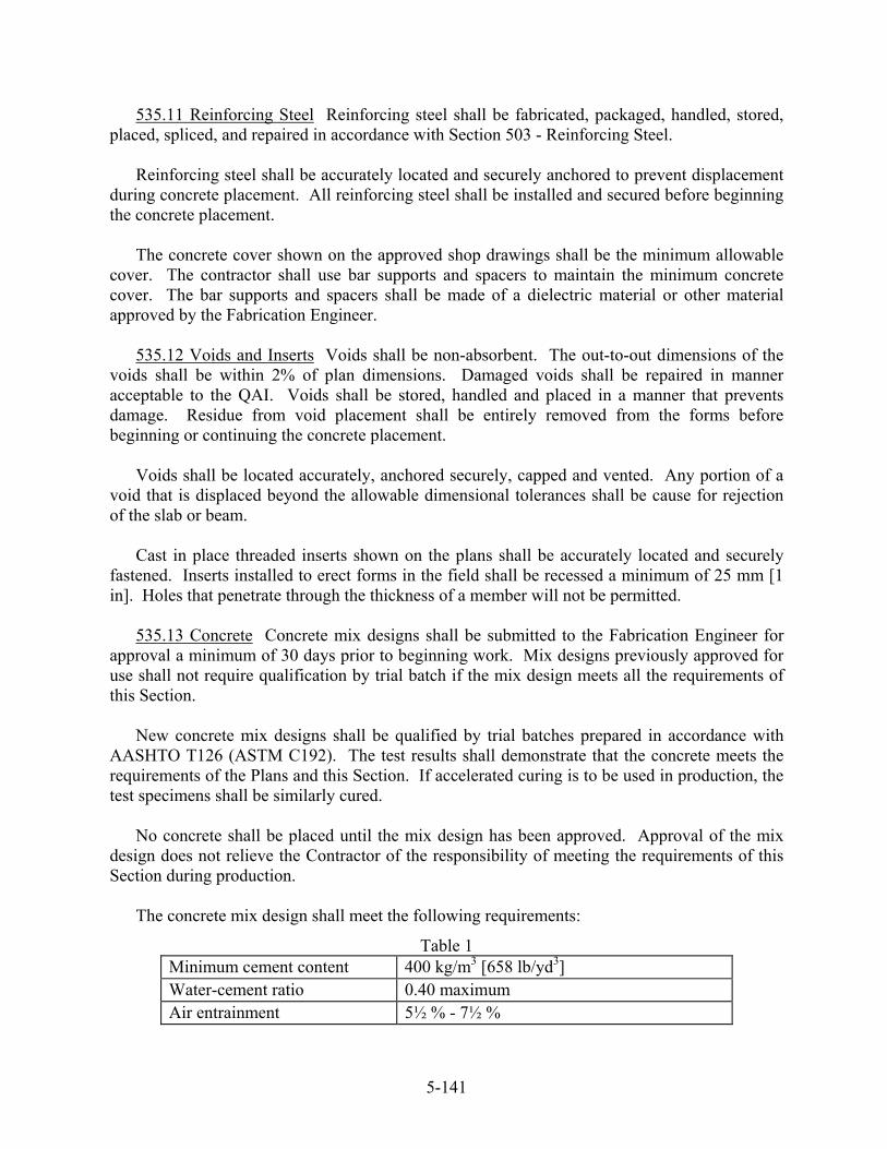
535.11 Reinforcing Steel Reinforcing steel shall be fabricated, packaged, handled, stored, placed, spliced, and repaired in accordance with Section 503 - Reinforcing Steel.
Reinforcing steel shall be accurately located and securely anchored to prevent displacement
during concrete placement. All reinforcing steel shall be installed and secured before beginning the concrete placement.
The concrete cover shown on the approved shop drawings shall be the minimum allowable
cover. The contractor shall use bar supports and spacers to maintain the minimum concrete cover. The bar supports and spacers shall be made of a dielectric material or other material approved by the Fabrication Engineer.
535.12 Voids and Inserts Voids shall be non-absorbent. The out-to-out dimensions of the
voids shall be within 2% of plan dimensions. Damaged voids shall be repaired in manner acceptable to the QAI. Voids shall be stored, handled and placed in a manner that prevents damage. Residue from void placement shall be entirely removed from the forms before beginning or continuing the concrete placement.
Voids shall be located accurately, anchored securely, capped and vented. Any portion of a
void that is displaced beyond the allowable dimensional tolerances shall be cause for rejection of the slab or beam.
Cast in place threaded inserts shown on the plans shall be accurately located and securely
fastened. Inserts installed to erect forms in the field shall be recessed a minimum of 25 mm [1 in]. Holes that penetrate through the thickness of a member will not be permitted.
535.13 Concrete Concrete mix designs shall be submitted to the Fabrication Engineer for
approval a minimum of 30 days prior to beginning work. Mix designs previously approved for use shall not require qualification by trial batch if the mix design meets all the requirements of this Section.
New concrete mix designs shall be qualified by trial batches prepared in accordance with
AASHTO T126 (ASTM C192). The test results shall demonstrate that the concrete meets the requirements of the Plans and this Section. If accelerated curing is to be used in production, the test specimens shall be similarly cured.
No concrete shall be placed until the mix design has been approved. Approval of the mix
design does not relieve the Contractor of the responsibility of meeting the requirements of this Section during production.
The concrete mix design shall meet the following requirements:
Table 1 Minimum cement content 400 kg/m3 [658 lb/yd3] Water-cement ratio 0.40 maximum Air entrainment 5½ % - 7½ %
5-141

Allowable slump 125 mm to 255 mm [5 in to 10 in] Calcium Nitrite* 14.85 L/m3 [3 gal/yd3] Silica Fume (when required) 5% - 10% of cement content by weight Fly Ash 40% of cementitious material maximum Slag 50% of cementitious material maximum
*The water in the Calcium Nitrite solution shall be included when calculating the water/cement ratio
The concrete mix design shall be proportioned such that the concrete achieves transfer strength within twenty-four hours of the completion of the placement. If two consecutive placements fail to meet the above requirement, no further placements shall take place until corrective action is taken by the Contractor.
The batching equipment, mixers and delivery equipment shall meet the requirements of
MNL 116. Concrete shall be batched, mixed and handled in accordance with MNL 116. 535.14 Concrete Placement The first two loads of concrete from each placement shall be
tested by the QCI for temperature, air entrainment, and slump. If the first load is unacceptable, the second load shall be tested as the first. This process shall continue until two consecutive loads are found acceptable. After two consecutive loads are found acceptable, the frequency of testing shall be at the discretion of the QAI.
Concrete shall be tested if there is a change in the dosage rate of any admixture, a change of
50 mm [2 in] or more in slump or a change of more than 3°C [5°F] in mix temperature. Any load of ¾ m³ [1 yd3] or less from a stationary mixer or 1½ m³ [2 yd3] or less from a
transit mixer shall be tested for air entrainment, slump, and temperature prior to being placed in the form.
Concrete shall be placed as nearly as possible to its final location. The depth of a lift shall
be controlled in order to minimize entrapped air voids. The maximum depth of an unconsolidated lift shall be 450 mm [18 in]. Concrete shall be vibrated with internal or internal and external vibrators. External vibrators shall not be used alone. Internal vibrators shall be inserted vertically and penetrate the lower layer of concrete by at least 100 mm [4 in]. The vibrators shall be inserted to assure that the radii of action of the vibrators overlap. The vibrators shall be held in position from 5 to 15 seconds. Vibrators shall not be used to move concrete horizontally.
When concrete placements are interrupted (e.g. placing voids in box beams), no more than
60 minutes shall elapse from the time of the beginning of the placement and the resumption of the concrete placement when the concrete temperature is below 24°C [75°F]. When the concrete temperature is above 24°C [75°F], the elapsed time shall be reduced to 30 minutes. Cold joints may make the unit subject to rejection.
5-142
No water shall be added to the concrete after batching. HRWR may be added to the concrete after batching if that practice conforms to the manufacturer’s published recommendations. Concrete that becomes unworkable shall be discarded.
535.15 Process Control Test Cylinders All process control test cylinders shall be made and
tested in accordance with the following Standards:
AASHTO T23 (ASTM C31/C31M) Practice for Making and Curing Concrete Test Specimens in Field
AASHTO T22 (ASTM C39) Test Method for Compressive Strength of Cylindrical Concrete Specimens
AASHTO T119 (ASTM C143) Test Method for Slump of Hydraulic Cement Concrete AASHTO T141 (ASTM C172) Practice for Sampling Freshly Mixed Concrete AASHTO T152 (ASTM C231) Test Method for Air Content of Freshly Mixed Concrete
by the Pressure Method ASTM C1064 - Test Method for Temperature of Freshly mixed Portland Cement
Concrete
A minimum of 8 concrete test cylinders shall be cast to represent each continuous concrete placement except that, 8 concrete test cylinders shall be made for each bulb “T” girder cast in a continuous placement. Six of the cylinders from each test shall be cured under the same conditions as the units. Unit identification, entrained air content, water-cement ratio, slump and temperature of the sampled concrete shall be recorded by the Contractor at the time of cylinder casting. Testing shall be done in the presence of the QAI. The QAI will designate the loads to be tested. Cylinders made to determine transfer strength shall be made during the last 1/3 of the placement.
At least once a week, the Contractor shall make four cylinders for use by the Department.
They shall be cured in accordance with AASHTO T23 (ASTM C31/C31M).
If the Contractor fails to make enough cylinders to demonstrate that the product meets the contract requirements, the product will be considered unacceptable.
The standard size test cylinder for acceptance shall be 150 mm by 300 mm [6 in by 12 in]. If 100 mm by 200 mm [4 in by 8 in] cylinders are used for acceptance, the compressive strength values shall be reduced by 5%. The compressive strength of the concrete shall be determined by averaging the compressive strength of two test cylinders made from the same load.
For the purpose of detensioning prestressed products, neither of the test cylinders shall have
a compressive strength less than the minimum required transfer strength after the 5% reduction 100 mm by 200 mm [4 in by 8 in] cylinders is taken.
For the purpose of acceptance, the average of two cylinders shall meet or exceed the design
strength, and, neither cylinder shall be more than 3.5 MPa [500 psi.] below the required strength.
5-143
Compressive testing to determine transfer and design strength shall be done in the presence of the QAI. Cylinder tests not witnessed by the QAI will not be acceptable.
535.16 Curing Immediately after the concrete has been finished, the product shall be
covered with an impermeable barrier to prevent moisture loss. The barrier shall be tight to the form and securely fastened. The exposed surface of the concrete shall be kept moist. The Contractor shall monitor and record the concrete temperature during the initial curing cycle.
After the product has been removed from the form, moist curing shall continue until it has
reached design strength. All surfaces of the product shall be kept moist and the product shall be placed in a moisture retention enclosure with a relative humidity not less than 80%. The product shall not be exposed to temperatures below 10°C [50°F] until design strength is achieved.
Membrane curing compounds shall not be used without the approval of the Fabrication
Engineer. If approved, the compound shall be applied in strict accordance with the manufacturer’s published instructions. The Contractor shall provide the QAI with the product data sheet for the compound prior to application. The compound shall be applied immediately after stripping.
535.17 Accelerated Curing (Optional) Accelerated curing shall begin after the concrete has
attained its initial set. Initial set shall be determined in accordance with ASTM C403, Standard Test Method for Time of Setting of Concrete Mixtures by Penetration Resistance. A strength gain of 3.5 MPa [500 psi.] indicates initial set. The Contractor shall provide documentation that the mix design being used has been tested in accordance with ASTM C403. Accelerated curing shall begin after the concrete has attained initial set. Application of heat more than 8 hours after initial set will not be considered accelerated curing.
The enclosure temperature may be increased by a maximum of 5.6°C/hr. [10°F/hour] prior
to initial set. The total temperature gain prior to initial set shall not exceed 22°C [40°F]. After initial set, the temperature gain of the concrete shall not exceed 22°C/hr. [40°F/hour].
The concrete temperature shall attain a minimum temperature of 50°C [120°F] and that temperature shall be maintained for a minimum of 8 hours. The maximum allowable concrete temperature shall be 82°C [180°F]. Concrete temperature shall be measured near each end of the casting bed and at intervals not to exceed 30 m [100 ft].
The cooling rate from maximum accelerated curing temperature shall not exceed 22°C/hour
[40°F/hour]. The cooling rate shall continue until the concrete temperature is within 22°C [40°F] of the ambient air temperature.
Steam curing shall take place in an enclosure that allows the free circulation of steam.
Steam jets shall provide a uniform distribution of steam without discharging directly on the product or the test cylinders.
5-144
When radiant heat is used, the Contractor shall take measures to assure that there is no moisture loss from the product. Free water shall be present on all exposed surfaces at all times.
Recording thermometers that indicate the time/temperature relationship shall be used by the
Contractor until transfer/stripping strength has been achieved. Copies of the time/temperature records shall be made available to the QAI.
If the units have achieved 80% of design strength during the curing cycle, no further curing
will be required. 535.18 Prestressing The Contractor shall provide stressing calculations to the QAI before
tensioning strands. Application of initial force and final tensioning shall be performed in the presence of the QAI. The QCI shall be present to witness and document the application of initial force, final tensioning and elongation of the strand.
Measurement of tensioning force shall be accomplished by one of the following:
a. Pressure gauges measuring hydraulic pressure b. Dynamometer c. Load cell-digital readout d. Digital readout connected to a transducer measuring hydraulic pressure
Equipment used to measure tensioning force shall be calibrated within 6 months of the beginning of the project. Calibration shall be performed by an approved testing laboratory, calibration service or under the direct supervision of a Professional Engineer registered in the State of Maine. Calibration shall be done in accordance with the manufacturer’s recommendations.
The Contractor shall provide a Calibration Report for the tensioning device being used. The
Calibration Report shall include a Calibration Conversion Chart that correlates gauge readings with actual force applied. The gauge reading used in production shall be interpolated using the gauge-force reading closest to the required force derived from the stressing calculations.
Equipment used to measure tensioning force shall be graduated to read within +/- 2% of the
anticipated force. Rams, gauges, pumps and hoses shall be calibrated together as a system. Replacement of any of the previously listed components shall require re-calibration of the jacking system. If the same device is used for initial and final tensioning, separate gauges shall be installed in the system. Both initial force and final tensioning hydraulic gauges shall be at least 150 mm [6 inches] in diameter and shall be graduated such that the anticipated force falls within the middle third of the gauge range. Gauges shall be at or near eye level and the needles shall remain steady until the load is released.
Strands shall be pulled in an orderly sequence to avoid snags and entanglements. When
strands from two or more coils or reel-less packs are used, the strands shall be identified by lot number. Elongation and adjusted gauge pressure readings shall be calculated for each modulus of elasticity and cross sectional area of the strands.
5-145
Prior to tensioning, hydraulic jacking devices shall be run until the hydraulic fluid is brought up to normal operating temperature. The jack shall be cycled several times to assure that the fluid in the lines is also at operating temperature.
Initial tensioning shall be done in the reverse order from that which the strand was pulled to
avoid friction and dead load losses due to overlying strand. After all strands have been initially tensioned, final tensioning shall begin. As an alternative, if the Contractor demonstrates that each strand is free of potential friction and dead load losses prior to reaching initial tension, the final tensioning force may be applied to the strand at that time. The Contractor shall visually inspect each strand during initial tensioning to assure that the strand is free of overlying strands or reinforcing steel.
After initial tensioning, the Contractor shall establish a permanent and clearly visible
reference mark on the strand to determine strand elongation after final tensioning. Strand elongation shall be measured to the nearest 2 mm [1/16 in]. The gauge pressure reading and strand elongation shall be within 5% of theoretical. The algebraic difference between the error in gauge reading and elongation shall not exceed 5%. If the elongation, gauge reading or the algebraic difference exceeds 5%, the tensioning operation shall be suspended until the Contractor determines the cause and makes corrections.
535.19 Detensioning Detensioning shall be carried out in the presence of the QAI and QCI. At the beginning of every job, the strands of each unit shall be marked and strand slippage
shall be measured and recorded by the QCI. The QAI may require that the strand slippage be measured on any unit if the QAI has reason to question the concrete consolidation around the strand.
Forms or any devices that restrict horizontal or vertical movement of the units shall be
loosened or removed before detensioning. The Contractor shall take measures to prevent damage, spalling or cracking, to the members that may be caused by detensioning.
Detensioning shall be performed in the sequence shown on the approved drawings. Failure
to follow this sequence shall be cause for rejection of the product. Detensioning shall be done as soon as it is practical after the units have achieved transfer
strength. If accelerated curing was used, detensioning shall be performed immediately following the curing period while the concrete is still warm and moist.
If detensioning is accomplished by single strand release, each strand shall be cut by heating
gradually with a low oxygen flame at both ends of the pre-stressing bed and at all intermediate points, in multiple unit casts, simultaneously. A minimum length of 150 mm [6 in] of strand shall be heated to prevent any shock or snap when the strand is finally severed. When possible, the strand should be cut a minimum of 450 mm [18 in] from the bulkhead of the form.
If detensioning is accomplished by multiple strand release, the equipment shall be capable of
releasing the load gradually, without shock, and with a minimum of movement of the units.
5-146

535.20 Finishing Concrete and Repairing Defects Products fabricated under this Section shall meet Standard Grade finish requirements as defined in MNL 116. The recommendations of Standard Grade finish requirements shall be mandatory. Fascia beams shall meet the requirements of finish Grade A.
Honeycombing, ragged or irregular edges and other cosmetic defects shall be repaired using
a product from the MDOT Prequalified List for Patching Materials. The repair, including preparation of the repair area, mixing, application and curing of the patching material shall be in accordance with the manufacturer’s published instructions. Edges not exposed in the final product may be ground smooth with no further repair necessary if the depth of the defect does not exceed 12 mm [½ in]. Form ties shall be removed to a depth of not less than 25 mm [1 in] from the face of the concrete and patched by a method approved by the Fabrication Engineer.
Structural defects shall be repaired by a method approved by the Fabrication Engineer. Structural defects shall include, but not be limited to exposed reinforcing steel or strand, cracks in bearing areas, through cracks and cracks 0.3 mm [0.013 in] in width that extend more than 300 mm [12 in]. The Contractor shall submit a proposed repair procedure for structural repairs to the Fabrication Engineer. No structural repairs shall be made without the QAI being present. The QAI shall be given adequate notice before beginning repairs.
Chamfers and drip notches shall be made smooth and uniform. Keyways shall be
sandblasted to remove mortar paste. Ends of strands shall be recessed 25 mm [1 in] and shall be patched and coated with a bituminous protective coating or, if exposed, sacked to a uniform finish.
535.21 Precast Deck Panels Precast deck panels shall be produced in accordance with the
plans and Standard Details, PRECAST CONCRETE DECK PANELS. Temporary supports for precast deck panels shall consist of continuous high-density expanded polystyrene strips. As an alternative, non-corrosive embedded inserts, threaded leveling jacks and compressible foam seals or other sealing devices may be used to support the precast deck panels.
535.22 Tolerances Tolerances for precast units shall be in conformance with the latest
edition of MNL 116, as applicable. Voided slabs shall be manufactured to the following tolerances:
Precast, Prestressed Voided Slabs Depth of Slab +/- 6 mm [+/- ¼ in] Width of Slab +/- 6 mm [+/- ¼ in]
Length of Slab +/- 3 mm /3 m [+/- ⅛ in/10 ft] of length or 13 mm [½ in], whichever is greater
Skewed Ends +/- 6 mm [+/- ¼ in](deviation from required skew) Beam Seat Bearing Area +/- 2 mm [+/- 1/16 in]
Horizontal Alignment +/- 6 mm [+/- ¼ in] (deviation from straight line parallel to centerline of member)
Dowel Tubes +/- 6 mm {+/- ¼ in] (center of tubes to sides of member) Void Tubes +/- 6 mm [+/- ¼ in] (vertically and horizontally)
5-147

or +/- 13 mm [+/- ½ inch] (location of ends) Post Tension Ducts +/- 6 mm [+/- ¼ in] Differential camber between Adjacent Units
+/- 3 mm /3 m [+/- ⅛ in/10 ft] of length or 13 mm [½ inch] maximum
Center of Gravity of Strand Group
+/- 6 mm [+/- ¼ in]
Stirrup Bars +/- 13 mm [+/- ½ in] projection above top of beam or +/- 25 mm [+/- 1 in] longitudinal spacing
535.23 Transportation and Storage After the prestressed products are detensioned, they may
be handled and moved, but shall not be transported until the 28 day design strength has been attained.
Prestressed products shall be transported so that the reactions with respect to the unit shall be approximately the same during transportation and storage as the product in its final position. The product shall be handled so that only a vertical force is applied to the lifting devices.
Stored products shall be supported above the ground on dunnage in a manner to prevent twisting or distortion. Products shall be protected from discoloration and aesthetic damage.
Units damaged by improper storing, hoisting or handling shall be replaced by the
Contractor. 535.24 Bearings When longitudinal keys are to be grouted, the post-tensioning strand shall
be tensioned to 22 kN [5 kips]. Prestressed units shall not be placed upon bearing areas that are improperly finished. Bearing shall be installed in conformance with Section 523 - Bearings. Elastomer sheets (non-laminated bearing pads) shall be installed as shown on the plans.
535.25 Keyway Grout Longitudinal keyways between beams shall be filled with a non-
shrink, flowable, cementitious grout with a design compressive strength of 42 MPa [6000 psi.]. The grout shall be one of the products listed on the Maine Department of Transportation’s list of Pre-qualified Grout Materials for Keyways. The grout shall be mixed, placed and cured in accordance with the manufacturer’s published recommendations. Gaskets of compressible material are required around duct openings within keyways to prevent blocking of the duct with grout.
Immediately before filling the keyway, it shall be cleared of debris. The keyway surfaces
shall be soaked with water prior to placement of grout. The keyways shall be sealed to prevent material loss.
535.26 Lateral Post-Tensioning A final tension of 129,000 N [29,000 lb] per strand shall be
applied to lateral post-tensioning strands. After tensioning, the ends of the strands shall be sawn or abrasion cut not less than 32 mm
[1¼ in] from the end of the wedge. The tendon tail and the gripping part of the anchorage shall
5-148

5-149
be coated with a corrosion inhibiting grease and then capped with a watertight covering. The entire anchorage shall be watertight.
Recesses at ends of lateral post-tensioning ducts shall be filled with grout using the same
type cement as that in the prestressed slabs. Prior to installing the grout, the stressing pockets shall be clean of any dirt, grease, oil, or other material that may prevent bonding. Grouting shall be completed within 10 days of lateral post-tensioning. No vehicular traffic, including the Contractor’s equipment shall be allowed on the bridge until post-tensioning is complete.
535.27 Erection of Precast Deck Panels Precast deck panels shall be erected as shown on
the plans. Foam temporary supports shall be attached to the outside edges of the top flanges of the girders with an adhesive applied in accordance with the manufacturer’s published recommendations. The foam shall be field-cut to adjust the bottom-of-slab elevations as required. If threaded jacking devices are cast into the panels, the bottom-of-slab elevations shall be adjusted with the jacks.
After the precast deck panels have been erected, adjusted and sealed, the void between the
top of the girder flange and the bottom of the panels shall be filled with a non-shrink, flowable, cementitious grout with a design compressive strength of 42 MPa [6000 psi.]. The grout shall be one of the products listed on the Maine Department of Transportation’s list of Pre-qualified Grout Materials for Keyways. The grout shall be mixed, placed and cured in accordance with the manufacturer’s published recommendations. Vent holes shall be provided at 1 m [3 ft] intervals to prevent air lock.
Before placing cast-in-place concrete on the precast deck panels, the joints shall be caulked
to prevent seepage of concrete paste. Oil, grease and other contaminants that may prevent a bond between the precast deck panels
and the cast-in-place concrete shall be removed by abrasive blast cleaning.
535.28 Method of Measurement Prestressed structural concrete will be measured by the lump sum.
535.29 Basis of Payment All work done under Prestressed Structural Concrete will be paid for at the contract lump sum price. Payment will be full compensation for furnishing all materials in the precast/pre-stressed unit including anchor dowels, reinforcing steel, and related materials and work. Related materials and work will include, but not be limited to, preformed pads, erecting the products, drilling and grouting of anchor dowels, grouting of keyways and ducts, post-tensioning operations and concrete admixtures used.
Payment will be made under:
Pay Item Pay Unit 535.60 Prestressed Structural Concrete Slab Lump Sum 535.61 Prestressed Structural Concrete I-Girders Lump Sum 535.62 Prestressed Structural Concrete Box Beams Lump Sum