DIVISION 500 - CONCRETE PAVEMENT - IN.gov
84
403 DIVISION 500 – CONCRETE PAVEMENT SECTION 501 – QC/QA PORTLAND CEMENT CONCRETE PAVEMENT, PCCP 501.01 Description This work shall consist of QC/QA portland cement concrete pavement, PCCP, placed on a prepared subgrade or subbase in accordance with 105.03. 501.02 Quality Control The mixture for PCCP shall be produced by an approved plant in accordance with ITM 405, transported, and placed according to a QCP, prepared and submitted by the 10 Contractor in accordance with ITM 803, for PCCP. The QCP shall contain a plan for placing PCCP in cold weather, as defined in 501.15. The cold weather plan shall, at a minimum, provide details to address changes in materials, concrete batching and mixing processes, construction methods, curing, temperature monitoring, and protection of in-situ PCCP. Temperature monitoring shall consist of monitoring the surface temperature of the PCCP by use of a thermometer. The thermometer shall be capable of recording and maintaining a record of the day, time, and temperature every 15 minutes around the clock. The thermometer shall be located 6 in. in from the edge of the PCCP. The QCP shall be submitted to the Engineer at least 15 days prior to commencing PCCP paving operations. 20 An American Concrete Institute certified concrete field testing technician, grade I, shall be on site to direct all sampling and testing. A common testing facility shall be provided for both production control and acceptance testing. MATERIALS 501.03 Materials 30 Materials shall be in accordance with the following: Admixtures ......................................................................... 912.03 Concrete Coarse Aggregate, Class AP ............................... 904.03, ITM 226 Fine Aggregate, Size No. 23 * ............................................. 904.02 Fly Ash ............................................................................... 901.02 Portland Cement ................................................................. 901.01(b) Rapid Setting Patch Materials ............................................ 901.07 Silica Fume ......................................................................... 901.04 Slag Cement ....................................................................... 901.03 40 Water .................................................................................. 913.01 * Type IS-A and Type IP-A blended cements shall not be used. 501.03
Transcript of DIVISION 500 - CONCRETE PAVEMENT - IN.gov

403
DIVISION 500 – CONCRETE PAVEMENT
SECTION 501 – QC/QA PORTLAND CEMENT CONCRETE PAVEMENT, PCCP
501.01 Description This work shall consist of QC/QA portland cement concrete pavement, PCCP, placed on a prepared subgrade or subbase in accordance with 105.03. 501.02 Quality Control The mixture for PCCP shall be produced by an approved plant in accordance with ITM 405, transported, and placed according to a QCP, prepared and submitted by the 10 Contractor in accordance with ITM 803, for PCCP. The QCP shall contain a plan for placing PCCP in cold weather, as defined in 501.15. The cold weather plan shall, at a minimum, provide details to address changes in materials, concrete batching and mixing processes, construction methods, curing, temperature monitoring, and protection of in-situ PCCP. Temperature monitoring shall consist of monitoring the surface temperature of the PCCP by use of a thermometer. The thermometer shall be capable of recording and maintaining a record of the day, time, and temperature every 15 minutes around the clock. The thermometer shall be located 6 in. in from the edge of the PCCP. The QCP shall be submitted to the Engineer at least 15 days prior to commencing PCCP paving operations. 20 An American Concrete Institute certified concrete field testing technician, grade I, shall be on site to direct all sampling and testing. A common testing facility shall be provided for both production control and acceptance testing.
MATERIALS 501.03 Materials 30 Materials shall be in accordance with the following: Admixtures ......................................................................... 912.03 Concrete Coarse Aggregate, Class AP ............................... 904.03, ITM 226 Fine Aggregate, Size No. 23* ............................................. 904.02 Fly Ash ............................................................................... 901.02 Portland Cement ................................................................. 901.01(b) Rapid Setting Patch Materials ............................................ 901.07 Silica Fume ......................................................................... 901.04 Slag Cement ....................................................................... 901.03 40 Water .................................................................................. 913.01 * Type IS-A and Type IP-A blended cements shall not be used.
501.03
404
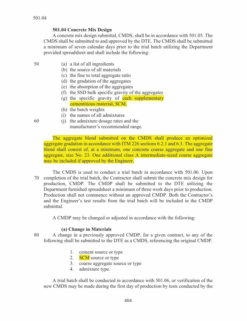
501.04 Concrete Mix Design A concrete mix design submittal, CMDS, shall be in accordance with 501.05. The CMDS shall be submitted to and approved by the DTE. The CMDS shall be submitted a minimum of seven calendar days prior to the trial batch utilizing the Department provided spreadsheet and shall include the following: (a) a list of all ingredients 50 (b) the source of all materials (c) the fine to total aggregate ratio (d) the gradation of the aggregates (e) the absorption of the aggregates (f) the SSD bulk specific gravity of the aggregates (g) the specific gravity of each supplementary
cementitious material, SCM, (h) the batch weights (i) the names of all admixtures (j) the admixture dosage rates and the 60
manufacturer’s recommended range. The aggregate blend submitted on the CMDS shall produce an optimized aggregate gradation in accordance with ITM 226 sections 6.2.1 and 6.3. The aggregate blend shall consist of, at a minimum, one concrete coarse aggregate and one fine aggregate, size No. 23. One additional class A intermediate-sized coarse aggregate may be included if approved by the Engineer. The CMDS is used to conduct a trial batch in accordance with 501.06. Upon completion of the trial batch, the Contractor shall submit the concrete mix design for 70 production, CMDP. The CMDP shall be submitted to the DTE utilizing the Department furnished spreadsheet a minimum of three work days prior to production. Production shall not commence without an approved CMDP. Both the Contractor’s and the Engineer’s test results from the trial batch will be included in the CMDP submittal. A CMDP may be changed or adjusted in accordance with the following: (a) Change in Materials A change in a previously approved CMDP, for a given contract, to any of the 80 following shall be submitted to the DTE as a CMDS, referencing the original CMDP. 1. cement source or type 2. SCM source or type 3. coarse aggregate source or type 4. admixture type. A trial batch shall be conducted in accordance with 501.06, or verification of the new CMDS may be made during the first day of production by tests conducted by the
501.04
405
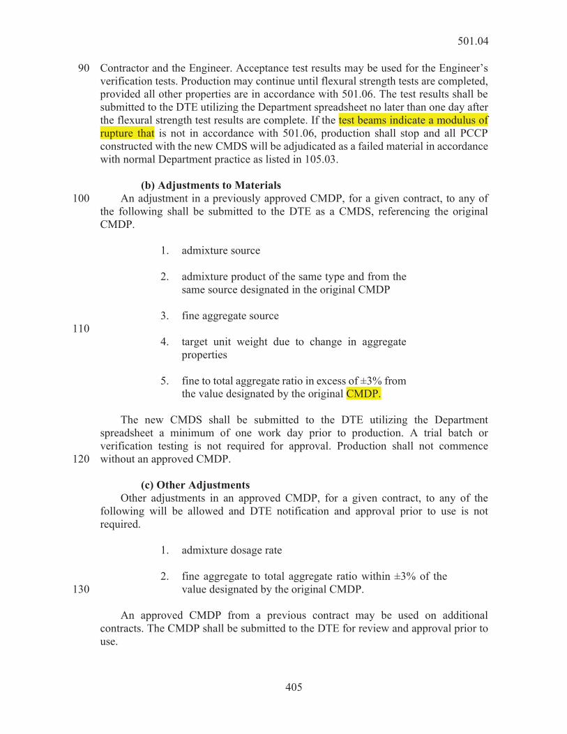
Contractor and the Engineer. Acceptance test results may be used for the Engineer’s 90 verification tests. Production may continue until flexural strength tests are completed, provided all other properties are in accordance with 501.06. The test results shall be submitted to the DTE utilizing the Department spreadsheet no later than one day after the flexural strength test results are complete. If the test beams indicate a modulus of rupture that is not in accordance with 501.06, production shall stop and all PCCP constructed with the new CMDS will be adjudicated as a failed material in accordance with normal Department practice as listed in 105.03. (b) Adjustments to Materials An adjustment in a previously approved CMDP, for a given contract, to any of 100 the following shall be submitted to the DTE as a CMDS, referencing the original CMDP. 1. admixture source 2. admixture product of the same type and from the
same source designated in the original CMDP 3. fine aggregate source 110 4. target unit weight due to change in aggregate
properties 5. fine to total aggregate ratio in excess of ±3% from
the value designated by the original CMDP. The new CMDS shall be submitted to the DTE utilizing the Department spreadsheet a minimum of one work day prior to production. A trial batch or verification testing is not required for approval. Production shall not commence without an approved CMDP. 120 (c) Other Adjustments Other adjustments in an approved CMDP, for a given contract, to any of the following will be allowed and DTE notification and approval prior to use is not required. 1. admixture dosage rate 2. fine aggregate to total aggregate ratio within ±3% of the
value designated by the original CMDP. 130 An approved CMDP from a previous contract may be used on additional contracts. The CMDP shall be submitted to the DTE for review and approval prior to use.
501.04

406
501.05 Concrete Mix Criteria The CMD shall contain at least one, but not more than two SCM’s, and produce workable concrete mixtures having the following properties: Minimum total cementitious content .................................. 450 lb/cu yd 140 Allowable amount of single SCM, % of total cementitious, by weight .............................. 25.0 - 40.0%* Allowable amount of two SCM’s, % of total cementitious, by weight... ........................... 25.0 – 40.0%** Minimum portland cement content ..................................... 275 lb/cu yd Allowable amount of silica fume as SCM, % of total cementitious content ................................... 3.0 – 7.0%** Maximum allowable water/cementitious ratio of concrete mixture with fly ash as SCM ................... 0.440 Maximum allowable water/cementitious ratio 150 of concrete mixture with slag cement as SCM ............ 0.450 Target Air Content .............................................................. 7.0% Minimum modulus of rupture............................................. 570 psi at 7 days * Binary binder systems shall contain either fly ash or slag cement
combined with a cement. If blended cement is used, it shall be
plant added slag cement or fly ash to create a binary binder system. or 160
will not be considered in calculating the amount of SCM. ** Ternary binder systems shall contain two SCM’s such as fly ash
and slag cement, or fly ash and silica fume, or slag cement and silica fume, combined with a cement. If a blended cement is used, it shall not be combined with a plant added SCM of the same type of pozzolan to create a ternary system. For example: a Type IP shall not be combined with plant-added fly ash and slag cement. When
170
cement will not be considered in calculating the amount of SCM. Silica fume shall only be a SCM component of a ternary binder system. If a blended cement is used, silica fume shall only be an SCM component of the ternary system.
Absorption tests shall be performed on the fine aggregate in accordance with AASHTO T 84 and on the coarse aggregate in accordance with AASHTO T 85. Absorption test results for a particular size of aggregate that differ by more than 1.0 percentage point from the Department’s source value shall be investigated. The 180 Contractor shall report any differences that exceed 1.0% to the Department. The Contractor’s results shall be used when calculating the water/cementitious ratio.
501.05

407
Hand placed paving operations meeting the requirements of 508.04(c) shall utilize concrete having a ternary binder system that contains silica fume as one of the SCM’s when the ambient temperature is below 50°F during placement or when the ambient temperature will fall below 50°F before the opening to traffic strength is attained. Concrete with a ternary binder system containing silica fume as one of the SCM’s, may be used in any approved method of pavement placement without restriction. Placement operations that involve form riding equipment in accordance with 190 508.04(b), may utilize an approved binary CMDP, without restriction. Water reducing admixture type A, or water reducing and retarding admixture type D, may be used in PCCP. However, admixture type A shall not be used in conjunction with admixture type D. 501.06 Trial Batch A trial batch shall be produced and tested by the Contractor’s certified technician to verify that the CMDS meets the concrete mix criteria. Concrete produced at a plant shall be batched within the proportioning tolerances of 508.02(b). Concrete batched in 200 a laboratory shall be in accordance with ASTM C192. The Engineer will test the trial batch and provide the Contractor with the results. The trial batch shall be of sufficient quantity to allow the Contractor and the Engineer to perform all required tests from the same batch. Trial batch concrete shall not be used for more than one test, except the concrete used for the unit weight may be used to conduct the air content test. The air content shall be 5.5% to 10.0%. The plastic unit weight shall be within ±3.0% from the target plastic unit weight of the CMDS. The water/cementitious ratio shall be within ±0.015 of the target value of the CMDS and shall not exceed the maximum amount allowed for the appropriate mix in accordance with 501.05. The flexural strength shall be determined by averaging a minimum of two beam breaks and shall 210 be a minimum of 570 psi. Test results shall be added to the Department spreadsheet and submitted to the DTE in accordance with 501.04. Adjustments to the target unit weight and the target water/cementitious ratio may be made. 501.07 Lots and Sublots q yds sublots of 2,400 sq yds of PCCP within a lot. Partial sublots of 480 sq yds or less will be added to the previous sublot. Partial sublots greater than 480 sq yds constitute a full 220 sublot. Partial lots of one or two sublots constitute a full lot. numbered and tested for a given pay item regardless of the number of CMD’s used and will be closed out at the end of the paving season or construction phase. 501.08 Acceptance Acceptance of PCCP will be based on the results of modulus of rupture, air content, unit weight, water/cementitious ratio, and thickness measurements obtained
501.08

408
by the Engineer in accordance with 505. The Engineer will randomly select the 230 location within each sublot for sampling in accordance with ITM 802. The random sample per sublot shall be of sufficient quantity to perform all required tests and obtained in accordance with AASHTO R 60. Concrete and necessary labor for sampling shall be furnished as required by the Engineer. The test results of the sublots for each lot will be averaged and shall be in accordance with 501.05 and 501.06, except the lot average for thickness shall be in accordance with 501.26. Test results are to be shared in a timely manner.
Test or Determination Frequency Test Method Precision
7-Day Flexural Strength two beams per sublot AASHTO T 97
modulus of rupture, rounded to
the nearest 5 psi
Air Content one test per sublot
AASHTO T 152 or ASTM C173 0.1%
Unit Weight one per sublot AASHTO T 121 0.1 lb/cu ft Water/Cementitious Ratio one per two lots ITM 403 0.001 Thickness two per sublot ITM 404 0.1 in.
240 Rounding will be in accordance with 109.01(a). In the event that an acceptance sample is not available to represent a sublot, all test results of the previous sublot will be used for acceptance. If the previous sublot is not available, the subsequent sublot will be used for acceptance.
CONSTRUCTION REQUIREMENTS 501.09 General Equipment for PCCP shall be in accordance with 508. 250 501.10 Preparation of Grade The subgrade shall be shaped to the required grade and section, free from all ruts, corrugations, or other irregularities, and uniformly compacted and approved in accordance with 207. 501.11 Preparation of Subbase Subbase, if required, shall be placed and shaped to the required grade and section in accordance with 302. Construction traffic shall not be allowed on the aggregate drainage layer of the subbase, except where PCCP placement is restricted. Exceptions 260 shall be submitted for approval. 501.12 Placement Placement of PCCP shall be by the slipformed or formed methods with equipment specified in 508.04. The subgrade or subbase shall be uniformly moist at the time of
501.09

409
PCCP placement. Excessively dry subgrade or subbase shall be sprinkled with water. 501.13 Process Control The Engineer and the Contractor will jointly review the operations to ensure compliance with the QCP. Continuous violations of compliance with the QCP will 270 result in suspension of paving operations. 501.14 Concrete Mixing and Transportation Concrete shall be mixed and delivered by one of the following: (a) Central mixed concrete shall be completely mixed in a
stationary mixer and transported in a truck agitator, truck mixer at agitating speed, or non-agitating equipment.
(b) Shrink mixed concrete shall be partially mixed in a 280
stationary mixer and the mixing completed during transportation in a truck mixer.
(c) Transit mixed concrete shall be completely mixed in a truck
mixer. The batch ticket for contract dedicated plants and delivery tickets for ready mix plants shall include the approved CMDP number. The tickets shall be delivered to the Engineer. 290 When the concrete temperature is 90°F or above, discharge from non-agitating equipment shall be completed within 30 minutes of mixing the water, cement, and aggregates. For concrete temperature below 90°F, discharge from non-agitating equipment shall be completed within 45 minutes of mixing the water, cement, and aggregates. The concrete temperature shall be measured in accordance with ASTM C1064 at the point of delivery. A watertight cover shall be used for a truck agitator and non-agitating equipment. The concrete shall be incorporated into the paving equipment within 15 minutes of discharge by the truck mixer, truck agitator, or non-agitating equipment. 300 Discharge from a truck agitator or a truck mixer shall be completed within 90 minutes of mixing the water, cement, and aggregates. Concrete shall be uniformly mixed when delivered to the job site. The Engineer may conduct additional testing to verify uniformity of the mixture. Additional testing will consist of slump tests taken in accordance with AASHTO T 119 at approximately the 1/4 and 3/4 points of a load. If the slumps differ by more than 1 in. when the average slump is 3 in. or less, or by more than 2 in. when the average slump is greater than 3 in., paving operations may be suspended while the mixing process is jointly 310 reviewed and problems resolved by the Engineer and the Contractor.
501.14

410
Wash water shall not be used as a portion of the mixing water. When concrete is delivered in transit mixers, additional water to increase the workability of a load may be added within 45 minutes of initial mixing per the QCP. Any addition of water shall be noted on the batch ticket and shall not occur as a continuing operation. 501.15 Weather Limitations 320 PCCP shall be placed when the ambient temperature is 32°F or rising. It shall not be placed on frozen subgrade or subbase. When the ambient temperature is at or below 40°F during PCCP placement, the cold weather plan shall be followed as outlined in the QCP in accordance with 501.02. Continuous temperature monitoring and recording shall be initiated for the day’s production when the ambient temperature is at or below 38°F at any time during placement for that day. Once monitoring has started, it shall continue uninterrupted until the opening to traffic strength, in accordance with 501.23, has been achieved. A 330 record of the temperature monitoring shall be furnished to the Engineer when the opening to traffic strength has been achieved. Prior to attaining opening to traffic strengths in accordance with 501.23, sufficient means shall be taken to prevent the PCCP from freezing. 501.16 Placing Concrete The batches shall be deposited so as to have a uniform mix and require as little rehandling as possible. The plastic concrete shall not be segregated during placement. Dowel bars and assemblies shall not be displaced during placement of concrete. 340 Concrete shall be thoroughly consolidated against the faces of all forms or adjacent concrete surfaces. Hand placed concrete shall be thoroughly consolidated with the use of a vibrator. Vibrators shall not operate in any one location so as to bring excessive mortar to the surface and shall not come in contact with a dowel bar assembly, subgrade, subbase, or forms. Concrete shall be placed around manholes or similar structures in accordance with 720. 350 The Contractor shall be responsible for the protection of the existing joints from the intrusion of fresh concrete mortar, and for any damage to existing pavement caused by the operation of mechanical equipment. Concrete materials that fall on or are worked into the joints or surface tines of an existing slab, shall be removed immediately. Concrete shall not be mixed, placed, or finished when the natural light is insufficient, unless an adequate and approved artificial lighting system is operated in
501.15

411
accordance with the QCP. 360 The Contractor shall have available at all times sufficient materials for the protection of unhardened PCCP from the effects of rain. Covering material such as burlap or polyethylene sheeting shall be provided. When rain appears imminent, paving operations shall stop. All available personnel shall be used to cover the PCCP. 501.17 Blank 501.18 Joints Joints shall be in accordance with 503. 370 501.19 Finishing PCCP shall be finished in accordance with 504. 501.20 Curing PCCP shall be cured with an approved white pigmented liquid membrane forming compound. Alternative methods of curing may be approved by the Engineer. Curing shall be in accordance with 504. For formed PCCP, immediately after the forms are removed, the sides of the PCCP shall be cured. 501.21 Form Removal 380 Forms may be removed as soon as the PCCP has hardened sufficiently to prevent edge spalling or other damage. Form pullers shall not be supported on the PCCP during form removal operations. 501.22 Pavement Inspection The Contractor and the Engineer will conduct an inspection of the new PCCP for any damage, including freezing or random cracks. The inspection and all necessary repairs shall be completed prior to opening the pavement to non-construction traffic. All random, full-depth cracks in the PCCP shall be corrected in accordance with 503.06. All other damage shall be repaired by approved methods. 390 501.23 Opening to Traffic The Contractor shall be responsible for controlling the opening of the PCCP to construction and non-construction traffic and include the procedures in the QCP. Pavement inspection will be completed in accordance with 501.22. PCCP may be opened to construction vehicles, equipment, and traffic when the flexural strength of the test beams indicates a modulus of rupture of 550 psi or greater. ITM 402 may be used as an alternate method to determine the flexural strength. If adequate strengths are not achieved, an investigation by the Engineer and the 400 Contractor will be conducted to determine if the PCCP is deficient. Resolutions for all deficiencies will be developed at the completion of the investigation. Cracks and joints shall be sealed in accordance with 503.05 and the PCCP cleaned prior to opening to traffic.
501.23

412
501.24 Pavement Corrugations Pavement corrugations shall be in accordance with 606. 501.25 Pavement Smoothness Pavement smoothness will be accepted by means of a profilograph, a 16 ft long 410 straightedge, or a 10 ft long straightedge as described below. (a) Profilograph When a pay item for Profilograph, PCCP is included in the contract, the Contractor shall furnish, calibrate, and operate an approved profilograph in accordance with ITM 912 for the acceptance of longitudinal smoothness on the mainline traveled way and ramps, including adjacent acceleration or deceleration lanes, where both of the following conditions are met: 1. The design speed is greater than 45 mph. 420 2. The traveled way or ramp lane width is
constant and is 0.1 mi in length or longer. The profilogram produced shall become the property of the Department. The profilograph shall remain the property of the Contractor. The project area, less paving exceptions and areas exempt from profilograph operation in accordance with ITM 912, will be divided into individual smoothness sections measuring 0.1 mi in length for each lane. Partial length smoothness sections adjacent to project limits, paving exceptions, or areas exempt from profilograph 430 operation will be considered in accordance with ITM 912. If the posted speed limit for an entire smoothness section is less than or equal to 45 mph, the section will be exempt from profilograph operation and the smoothness within the section will be accepted by a 16 ft straightedge. If the posted speed limit is greater than 45 mph for a portion of a smoothness section and is less than or equal to 45 mph for the remainder, the section smoothness acceptance will be as follows: 440 1. By profilograph for the portion of the section with a
posted speed limit greater than 45 mph. 2. By 16 ft straightedge for the portion of the section with
a posted speed limit less than or equal to 45 mph. At locations where the profilograph is required, all high or low point deviations which are greater than 0.30 in. shall be corrected. Corrections shall be made in accordance with 501.25(c). (b) 16 ft Straightedge and 10 ft Straightedge 450 The Department will furnish and operate 16 ft and 10 ft straightedges as described
501.24

413
below. The 16 ft straightedge is used to accept smoothness along the direction of mainline traffic and the 10 ft straightedge is used to accept smoothness transverse to the direction of mainline traffic. This includes longitudinal smoothness on public road approaches and median crossovers. For contracts which include the profilograph, PCCP pay item, the 16 ft long straightedge will be used to accept longitudinal smoothness at the following locations: 1. All mainline traveled way lanes shorter than 0.1 mi. 460 2. All mainline traveled way lanes within smoothness
sections with posted speed limits less than or equal to 45 mph throughout the entire section length.
3. All mainline traveled way lanes at locations exempted from
profilograph operation in accordance with ITM 912. 4. All tapers. 470 5. All turn lanes, including bi-directional left turn lanes. 6. All ramps with design speeds of 45 mph or less. 7. All acceleration and deceleration lanes associated with
ramps with design speeds of 45 mph or less. 8. All shoulders. For contracts where the profilograph is not used for smoothness acceptance, the 480 16 ft straightedge will be used to accept longitudinal smoothness at the above locations and on all mainline traveled way lanes and ramps with design speeds greater than 45 mph. Smoothness acceptance on ramp acceleration or deceleration lanes will also be accepted by the 16 ft straightedge. The 10 ft long straightedge shall be used for transverse slopes, approaches, and crossovers. As soon as the PCCP has cured sufficiently, the smoothness may be checked. The Department may direct that the pavement profile be evaluated within 24 h following 490 placement. When profile testing is consistently outside pavement surface tolerances the paving operation shall be discontinued until an amended QCP is submitted. (c) Smoothness Correction Pavement smoothness variations outside specified tolerances shall be corrected by grinding with a groove type cutter or by replacement. Grinding will not be allowed until the PCCP is 10 days old and flexural strength testing yields a modulus of rupture
501.25
414
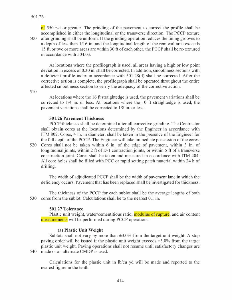
of 550 psi or greater. The grinding of the pavement to correct the profile shall be accomplished in either the longitudinal or the transverse direction. The PCCP texture after grinding shall be uniform. If the grinding operation reduces the tining grooves to 500 a depth of less than 1/16 in. and the longitudinal length of the removal area exceeds 15 ft, or two or more areas are within 30 ft of each other, the PCCP shall be re-textured in accordance with 504.03. At locations where the profilograph is used, all areas having a high or low point deviation in excess of 0.30 in. shall be corrected. In addition, smoothness sections with a deficient profile index in accordance with 501.28(d) shall be corrected. After the corrective action is complete, the profilograph shall be operated throughout the entire affected smoothness section to verify the adequacy of the corrective action. 510 At locations where the 16 ft straightedge is used, the pavement variations shall be corrected to 1/4 in. or less. At locations where the 10 ft straightedge is used, the pavement variations shall be corrected to 1/8 in. or less. 501.26 Pavement Thickness PCCP thickness shall be determined after all corrective grinding. The Contractor shall obtain cores at the locations determined by the Engineer in accordance with ITM 802. Cores, 4 in. in diameter, shall be taken in the presence of the Engineer for the full depth of the PCCP. The Engineer will take immediate possession of the cores. Cores shall not be taken within 6 in. of the edge of pavement, within 3 in. of 520 longitudinal joints, within 2 ft of D-1 contraction joints, or within 5 ft of a transverse construction joint. Cores shall be taken and measured in accordance with ITM 404. All core holes shall be filled with PCC or rapid setting patch material within 24 h of drilling. The width of adjudicated PCCP shall be the width of pavement lane in which the deficiency occurs. Pavement that has been replaced shall be investigated for thickness. The thickness of the PCCP for each sublot shall be the average lengths of both cores from the sublot. Calculations shall be to the nearest 0.1 in. 530 501.27 Tolerance Plastic unit weight, water/cementitious ratio, modulus of rupture, and air content measurements will be performed during PCCP operations. (a) Plastic Unit Weight Sublots shall not vary by more than ±3.0% from the target unit weight. A stop paving order will be issued if the plastic unit weight exceeds ±3.0% from the target plastic unit weight. Paving operations shall not resume until satisfactory changes are made or an alternate CMDP is used. 540 Calculations for the plastic unit in lb/cu yd will be made and reported to the nearest figure in the tenth.
501.26

415
(b) Water to Cementitious Ratio The weekly water to total cementitious materials ratio shall not vary more than ±0.030 of the target value or exceed the maximum allowed for the appropriate mixture in accordance with 501.05. A stop paving order will be issued if the test results exceed these values. Paving operations shall not resume until satisfactory changes are made or an alternate CMDP is used. 550 Calculations for water to cementitious ratio will be made and reported to the nearest figure in the third decimal place. (c) Flexural Strength Average lot values for modulus of rupture of 570 psi and above shall be achieved. Price adjustments for values outside the tolerance limits will be in accordance with 501.28. Calculations for modulus of rupture in psi will be made and reported to the nearest 560 5.0 psi. (d) Air Content The average lot air content values shall not vary more than - 1.2% to + 2.2% from the 7.0% target air content. The range of sublot air content values shall not exceed 2.5%. Price adjustments for values outside the tolerance limits or range will be in accordance with 501.28. Calculations for air content percentage will be made and reported to the nearest figure in the first decimal place. 570 501.28 Pay Factors When the PCCP measurements for air content, air content range, modulus of rupture, smoothness, and thickness exceed the allowable tolerances, pay factors will be determined. The pay factors will be used to calculate a quality assurance adjustment quantity for the lot. The adjustment for modulus of rupture, air content, air content range, thickness, and smoothness will be calculated as follows: 580
– 1.00) where:
q = quality assurance adjustment quantity lot quantity
U = unit price for QC/QA-PCCP, $/sq yd P = pay factor.
For sublot thickness determination:
qT = lT x U x (P – 1.00) where:
501.28

416
qT = quality assurance adjustment quantity lT = sublot quantity for thickness U = unit price for QC/QA-PCCP, $/sq yd P = pay factor.
The quality assurance adjustment points for smoothness, Qs, will be calculated in accordance with 501.28(d). 590 The total quality assurance adjustments will be calculated as follows:
QT T1 + qT2 + qT3), and Q F + qA + qR + QT) + QS
where: Q = total quality assurance adjustment quantity
QS = quality assurance adjustment for smoothness qF = lot quality assurance adjustments for modulus
of rupture from flexural strength testing QT = lot quality assurance adjustments for thickness qA = lot quality assurance adjustments for air content qR = lot quality assurance adjustments for range.
If the Contractor is not required to remove the pavement or take other corrective actions, quality assurance adjustments of the lot will be assessed as determined by the Department’s Division of Materials and Tests. 600 (a) Modulus of Rupture When test results for modulus of rupture from flexural strength testing exceed the allowable tolerance, a pay factor will be assessed as follows: 1. Lots
Modulus of Rupture Psi Pay Factors
570 and above 1.00 565 – 569 0.98 560 – 564 0.96 555 – 559 0.94 550 – 554 0.92 545 – 549 0.89 540 – 544 0.86 535 – 539 0.83 525 – 534 0.78 515 – 524 0.72 514 or less *
* The PCCP will be adjudicated as a failed material in accordance with normal Department practice as listed in 105.03. The PCCP may be subject to removal and replacement or left in place with reduced or no payment.
501.28

417
2. Sublots If an individual sublot value is less than 500 psi, the PCCP will be adjudicated as a failed material in accordance with normal Department practice as listed in 105.03. 610 For a sublot completely removed, the sublot test value from the replacement sublot will replace the original test value. (b) Air Content When test results for air content exceed the allowable tolerance or range, a pay factor will be assessed as follows: 1. Lots
Percent, % Pay Factors
> 9.8 * 9.7 9.8 0.85 9.5 – 9.6 0.95 9.3 – 9.4 0.99 5.8 – 9.2 1.00
5.7 0.93 5.6 0.90 5.5 0.85 5.4 0.79
< 5.4 * * The PCCP will be adjudicated as a failed material in accordance with
normal Department practice as listed in 105.03. The PCCP may be subject to removal and replacement or left in place with reduced or no payment.
Percent, % Pay Factors 0.0 – 2.5 1.00 2.6 – 3.0 0.99 3.1 – 3.5 0.97
> 3.5 * * The PCCP will be adjudicated as a failed material in accordance with
normal Department practice as listed in 105.03. The PCCP may be subject to removal and replacement or left in place with reduced or no payment.
620 2. Sublots If a sublot value is less than 5.5% or greater than 10.0%, the PCCP will be adjudicated as a failed material in accordance with normal Department practice in accordance with 105.03. For a sublot completely removed, the sublot test value from the replacement sublot will replace the original test value. (c) Thickness When test results for pavement thickness do not meet the specified thickness, a pay factor will be assessed as follows:
501.28

418
630 Sublot Pay Factors for Thickness
Average core depth, ACD Design depth, DD
ACD minus DD Pay Factor > +0.5 in. 1.05
+0.3 in. to +0.5 in. 1.02 ±0.2 in. 1.00
0.3 in. to 0.5 in. 0.96 0.6 in. to 0.7 in. 0.90 0.8 in. to 1.0 in. 0.80
< 1.00 in. * * The PCCP will be adjudicated as a failed material in accordance with normal
Department practice as listed in 105.03. The PCCP may be subject to removal and replacement or left in place with reduced or no payment.
(d) Smoothness When the pavement smoothness is tested with a profilograph, pavement will be based on a zero blanking band on the final profile index. A Quality Assurance Pay Factor, PFs, for smoothness will apply to the planned thickness of the PCCP. The quality assurance adjustment for each section will include the total area of each pavement lane measured by the profilograph for 0.1 mi long section represented by the profile index calculated by the following formula:
qs = (PFs – 1.00) x A x U 640 where:
qs = quality assurance adjustment for smoothness for one section PFs = pay factor for smoothness
A = area of the section, sq yd U = unit price for the material $/sq yd.
For smoothness sections that are less than 0.1 mi in length or require profilograph operation along both lane edges, the profile index used to obtain the smoothness pay factor used in the above formula will be determined in accordance with ITM 912. The quality assurance adjustment for smoothness, Qs, for the contract will be the total of the quality assurance adjustments for smoothness, qs, on each section by the following formula: 650
Qs s Regardless of the tabulated value, the maximum pay factor for a smoothness section where corrective action has been performed will be 1.00.
501.28

419
Pay Factors for Smoothness (PI0.0) Zero Blanking Band
Design Speed greater than 45 mph Profile Index, in./0.1 mi. Pay Factor, PFs
over 0.00 to 1.40 1.06 over 1.40 to 1.60 1.05 over 1.60 to 1.80 1.04 over 1.80 to 2.00 1.03 over 2.00 to 2.40 1.02 over 2.40 to 2.80 1.01 over 2.80 to 3.60 1.00 over 3.60 to 3.80 0.96
All pavements with a Profile Index, PI0.0, greater than 3.80 in. shall be corrected to a profile index less than or equal to 3.80 in.
501.29 Appeals If the Contractor does not agree with the acceptance test results, a request may be made in writing for additional tests for a sublot or lot. The basis of the appeal shall 660 include applicable QC test results showing acceptable quality results and shall be submitted within five calendar days of receipt of the Department’s written results for that lot. Upon review of the appeal, the Engineer may accept the PCCP in accordance with 105.03 or accept the appeal. (a) Modulus of Rupture Appeals will not be considered unless QC test results for modulus of rupture obtained from flexural strength testing indicate greater than a 50 psi difference between the Department’s and the Contractor’s test results. Upon approval for the additional testing, the Contractor shall obtain cores, as directed, in the presence of the 670 Engineer. The Engineer will determine the location of the cores within the appealed and adjacent sublots using the same CMD. The location of the cores will be at the center of a lane at the acceptance sample location. Cores shall not be taken over dowels or within 5 ft of a header. Two cores shall be taken in each sublot for the full depth of pavement and shall be 4 in. in diameter. All core holes shall be filled with portland cement concrete within 24 h of drilling. If adjacent sublots were produced using different CMDs, the matter will be adjudicated as a failed material in accordance with normal Department practice. 680 Each core will be tested for split tensile strength in accordance with ASTM C496. The cores will be submerged in lime saturated water prior to testing for a minimum of 40 h. The average core split tensile strength will be determined for the appealed and adjacent sublots. Modulus of rupture will be calculated as follows:
501.29

420
2A
2A
1A
1ADD S2
FS2F x SF
690 where:
FD = modulus of rupture of the appealed sublot FA1 = modulus of rupture of the previous adjacent sublot FA2 = modulus of rupture of the subsequent adjacent sublot SD = split tensile strength of the appealed sublot
SA1 = split tensile strength of the previous adjacent sublot SA2 = split tensile strength of the subsequent adjacent sublot.
(b) Air Content Appeals will not be considered unless QC test results indicate greater than a 0.5% difference between the Department’s and the Contractor’s tests. Upon approval for the additional testing, the Contractor shall obtain core as directed in the presence of the Engineer. The Engineer will determine the location of the core within the appealed sublot. The location of the core will be at the center of a lane at the acceptance sample location. 700 A core shall not be taken over dowels or within 5 ft of a header. One 4 in. diameter full depth core shall be taken from the pavement for each sublot appealed. All core holes shall be filled with PCC or rapid setting patch material within 24 h of drilling. The air content for a sublot will be the hardened concrete air content determined from the core in accordance with ITM 401. When ACBF aggregates are used, the hardened concrete air content will be determined in accordance with ASTM C457. 501.30 Method of Measurement QC/QA-PCCP will be measured by the square yard of the thickness specified. The 710 area of QC/QA-PCCP will be the planned width of the pavement multiplied by the length of the pavement, or as directed in writing. The width of the pavement will be as shown on the typical cross section of the plans. The length of the pavement will be measured parallel to the surface of the pavement along the centerline of the roadway or ramp, excluding paving exceptions as shown on the plans. Milled pavement corrugations will be measured in accordance with 606.02. 501.31 Basis of Payment The accepted quantities of QC/QA-PCCP will be paid for at the contract unit price 720 per square yard for the thickness specified, complete in place. Payment for furnishing, calibrating, and operating the profilograph, and furnishing profile information will be made at the contract lump sum price for profilograph, PCCP.
501.30

421
Adjustments to the contract payment due to measurements for modulus of rupture, thickness, air content, range and smoothness will be included in a quality assurance adjustment pay item in accordance with 109.05.1. 730 Milled pavement corrugations will be paid for in accordance with 606.03. Payment for pavement thickness determinations will be made at the contract lump sum price for coring, PCCP. A change order in accordance with 109.05 will be developed to adjust the cost of coring when the final QC/QA-PCCP quantity differs from the bid quantity by more than 2,400 sq yds. This adjustment covers the cost of cores for the adjusted quantity of QC/QA-PCCP. The adjustment, plus or minus, will be based on the difference in the number of sublots, rounded to the nearest full sublots, times $100. 740 Payment will be made under: Pay Item Pay Unit Symbol Coring, PCCP ............................................................................ Profilograph, PCCP ................................................................... QC/QA-PCCP, __________ in.................................................. SYS thickness The cost of trial batch demonstrations shall be included in the cost of PCCP. 750 The price of profilograph, PCCP will be full compensation regardless of how often the profilograph is used or how many profilograms are produced. The cost of corrections for pavement smoothness and re-texturing shall be included in the cost of QC/QA-PCCP. The cost of coring and refilling of the pavement holes for appeals shall be included in the cost of QC/QA-PCCP. 760 The cost of temperature monitoring and recording during cold weather placement shall be included in the cost of QC/QA-PCCP. Traffic control for appeals shall be supplied with no additional payment. Removal and replacement of QC/QA-PCCP damaged by freezing shall be with no additional payment.
501.31

422
SECTION 502 – PORTLAND CEMENT CONCRETE PAVEMENT, PCCP 502.01 Description This work shall consist of portland cement concrete pavement, PCCP, placed on a prepared subgrade or subbase in accordance with 105.03.
MATERIALS 502.02 Materials Materials shall be in accordance with the following: 10 Admixtures ......................................................................... 912.03 Concrete Coarse Aggregate, Class AP ............................... 904.03, ITM 226 Fine Aggregate, Size No. 23 ............................................... 904.02 Fly Ash ............................................................................... 901.02 Portland Cement ................................................................. 901.01(b) Rapid Setting Patch Materials ............................................ 901.07 Silica Fume ......................................................................... 901.04 Slag Cement ....................................................................... 901.03 Water .................................................................................. 913.01 20 502.03 Concrete Mix Design A concrete mix design submittal, CMDS, shall be in accordance with 502.04. The CMDS shall be submitted to the DTE. The CMDS shall be submitted a minimum of seven calendar days prior to production. The CMDS shall use the Department provided spreadsheet and shall include the following: (a) a list of all ingredients (b) the source of all materials (c) the fine to total aggregate ratio 30 (d) the absorption of the aggregates (e) the SSD bulk specific gravity of the aggregates (f) the specific gravity of pozzolan (g) the batch weights (h) the names of all admixtures (i) the admixture dosage rates and the manufacturer’s
recommended range. The aggregate blend submitted on the CMDS shall produce an optimized aggregate gradation in accordance with ITM 226 sections 6.2.1 and 6.3. The aggregate 40 blend shall consist of, at a minimum, one Concrete Coarse Aggregate and one fine aggregate, No. 23. One additional class A or higher intermediate-sized coarse aggregate may be included if approved by the Engineer. The absolute volume of the mix design shall be 27.0 cu ft at the design air content of 6.5%.
502.01

423
Production shall not commence until the DTE has assigned a mix number to the CMDS. The mix design will henceforth be identified as a concrete mix design for production, CMDP. 50 Any of the following changes or adjustments to an existing CMDP shall require a new CMDS to be submitted to the DTE. (a) cement source or type (b) pozzolan source or type (c) aggregate source or type (d) admixture source or type (e) addition or deletion of an admixture (f) proportioning of the concrete in accordance with 502.04 as 60
follows: 1. cement content or cement reduction 2. pozzolan to cement substitution ratio 3. target water/cementitious ratio 4. proportion of aggregate by weight exceeding ±2%. A CMDP in accordance with 501.05 or a CMDP in accordance with 502.04 from a previous contract may be submitted for review for use on the current contract to the DTE. The DTE will notify the Contractor when the review is complete and whether or 70 not the previously used CMDP can be used on the current contract. 502.04 Concrete Mix Criteria Chemical admixtures type A, type B, type C, type D, type E, and type F may be allowed if shown on the CMDP. The supplied concrete mix shall include one of the following water reducing admixtures: type A, type D, type E, or type F. (a) Portland Cement Concrete The CMD shall produce workable concrete mixtures, with the minimum amount of water, and having the following properties. 80 Targets for the CMD: Portland cement content ..................................................... 564 lb/cu ydA Maximum portland cement content .................................... 752 lb/cu ydA Minimum water/cementitious ratio .................................... 0.340B Maximum water/cementitious ratio .................................... 0.435B Maximum portland cement reduction for slag cement replacement ........................................ 30% Slag cement/portland cement substitution ratio .................. 1.00 by weight 90 Maximum cement reduction for fly ash replacement ......... 20% Fly ash/portland cement substitution ratio .......................... 1.25 by weight Air Content ......................................................................... 6.5%
502.04
424
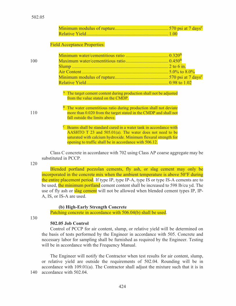
Minimum modulus of rupture............................................. 570 psi at 7 daysC Relative Yield ..................................................................... 1.00 Field Acceptance Properties: Minimum water/cementitious ratio .................................... 0.320B Maximum water/cementitious ratio .................................... 0.450B 100 Slump ................................................................................. 2 to 6 in. Air Content ......................................................................... 5.0% to 8.0% Minimum modulus of rupture............................................. 570 psi at 7 daysC Relative Yield ..................................................................... 0.98 to 1.02 A The target cement content during production shall not be adjusted
from the value stated on the CMDP. B The water cementitious ratio during production shall not deviate
more than 0.020 from the target stated in the CMDP and shall not 110 fall outside the limits above.
C Beams shall be standard cured in a water tank in accordance with
AASHTO T 23 and 505.01(a). The water does not need to be saturated with calcium hydroxide. Minimum flexural strength for opening to traffic shall be in accordance with 506.12.
Class C concrete in accordance with 702 using Class AP coarse aggregate may be substituted in PCCP. 120 Blended portland pozzolan cements, fly ash, or slag cement may only be incorporated in the concrete mix when the ambient temperature is above 50°F during the entire placement period. If type IP, type IP-A, type IS or type IS-A cements are to be used, the minimum portland cement content shall be increased to 598 lb/cu yd. The use of fly ash or slag cement will not be allowed when blended cement types IP, IP-A, IS, or IS-A are used. (b) High-Early Strength Concrete Patching concrete in accordance with 506.04(b) shall be used. 130 502.05 Job Control Control of PCCP for air content, slump, or relative yield will be determined on the basis of tests performed by the Engineer in accordance with 505. Concrete and necessary labor for sampling shall be furnished as required by the Engineer. Testing will be in accordance with the Frequency Manual. The Engineer will notify the Contractor when test results for air content, slump, or relative yield are outside the requirements of 502.04. Rounding will be in accordance with 109.01(a). The Contractor shall adjust the mixture such that it is in accordance with 502.04. 140
502.05

425
CONSTRUCTION REQUIREMENTS 502.06 General Equipment for PCCP shall be in accordance with 508. Aggregate stockpiles shall be located in well drained areas to prevent the soil from pumping into and contaminating the aggregate that is to be used in PCCP. Stockpiles shall be built in layers not to exceed 6 ft. Upper layers shall be prevented from spilling onto the lower layers. 150 Aggregate stockpiles shall be worked to minimize segregation and maintain uniform moisture content. Aggregates which have become contaminated shall not be used. The water measuring device will be checked under actual working conditions or at any other time deemed necessary. All labor and equipment required for calibrating and checking shall be furnished. The volume of the batched concrete shall not exceed the manufacturer’s standard 160 rating for the concrete mixer. 502.07 Preparation of Grade The subgrade shall be shaped to the required grade and section, free from all ruts, corrugations, or other irregularities, and uniformly compacted and approved in accordance with 207. Surfaces on which a mixture is placed shall be free from objectionable or foreign materials at the time of placement. 502.08 Preparation of Subbase Subbase, if required, shall be placed and shaped to the required grade and section 170 in accordance with 302. Construction traffic shall not be allowed on the aggregate drainage layer of the subbase, except where PCCP placement is restricted. Exceptions shall be submitted for approval. 502.09 Placement Placement of PCCP shall be by the slipformed or formed methods with equipment specified in 508.04. The subgrade or subbase shall be uniformly moist at the time of PCCP placement. Excessively dry subgrade or subbase shall be sprinkled with water. If the slip-form method is used the subgrade or subbase shall firmly support the 180 paving equipment to construct the specified alignment and grade. The slip-form paver shall be operated with as nearly a continuous forward movement as possible. If it is necessary to stop the forward movement of the paver, the vibratory and tamping elements shall also be stopped. Edge slump of PCCP shall not exceed 1/4 in. When the slip-form method is used, the Contractor shall have metal or wood forms available for protection of the PCCP edges should excessive edge slump occur.
502.09

426
If forms are used they shall be firmly supported by the subbase or subgrade for the entire length of the form at the specified alignment and grade. The alignment of 190 the forms shall not deviate more than 1/4 in. in the horizontal direction from the planned PCCP width for tangent sections. Forms shall be staked into place with a minimum of three pins for each 10 ft section. A pin shall be placed at each side of every joint. Form sections shall be locked tightly and be free from play or movement in any direction. No excessive settlement or springing of forms under the finishing machine will be allowed. Forms shall be cleaned and oiled prior to the placing of concrete. Forms shall be kept a minimum of 500 ft ahead of concrete placement when 200 distance allows. Any material displaced during form setting operations shall be thoroughly compacted. If material under the forms becomes unstable before concrete is placed, the forms shall be removed, the grade corrected, and the forms reset. 502.10 Concrete Mixing and Transportation Concrete mixing and transportation shall be completed by central mixed, shrink mixed, or transit mixed methods. The minimum batch of concrete shall be 2 cu yds. When the concrete temperature is 90°F or above, discharge from non-agitating equipment shall be completed within 30 minutes of mixing the water, cement, and aggregates. For concrete temperature below 90°F, discharge from non-agitating 210 equipment shall be completed within 45 minutes of mixing the water, cement, and aggregates. The concrete temperature will be measured in accordance with ASTM C1064 at the point of delivery. Discharge from a truck agitator or a truck mixer shall be completed within 90 minutes of mixing the water, cement, and aggregates. Concrete shall be uniformly mixed when delivered to the job site. Batch tickets for each load of PCC shall indicate the weight of cement, pozzolan, and aggregates, volume or weight of water, and the type and volume of admixtures. The weight of the cement shall be within 1% of the CMDP, the saturated surface dry weight of the aggregates shall be within 2% of the CMDP, and the volume or weight of water shall 220 be within 1% of the required amount. The Engineer may conduct additional testing to verify uniformity of the mixture. Additional testing will consist of slump tests taken in accordance with AASHTO T 119 at approximately the 1/4 and 3/4 points of a load. If the slumps differ by more than 1 in. when the average slump is 3 in. or less, or by more than 2 in. when the average slump is greater than 3 in., paving operations may be suspended while the mixing process is jointly reviewed and problems resolved by the Engineer and the Contractor. 230 Wash water shall not be used as a portion of the mixing water. When concrete is delivered in transit mixers, additional water to increase the
502.10

427
workability of a load may be added within 45 minutes of initial mixing. Any addition of water shall be noted on the batch ticket and shall not occur as a continuing operation. Stationary mixers shall be operated at the manufacturer’s recommended drum speed. Batches shall not exceed the nominal capacity of the mixer. (a) Central Mixed Concrete 240 Central mixed concrete shall be completely mixed in a stationary mixer and transported in a truck agitator, truck mixer at agitating speed, or non-agitating equipment. Mixing for central mixed concrete shall be no less than 60 s per batch. The mixing time shall be measured from the time all cement and aggregates are in the drum. The batch shall be so discharged into the mixer that some of the water enters in advance of the cement and aggregates. All required water shall be in the drum by the end of the first quarter of the specified mixing time. 250 If a truck mixer or truck agitator is used for transportation, the concrete shall be agitated at the agitation speed designated by the manufacturer. (b) Shrink Mixed Concrete Shrink mixed concrete shall be partially mixed in a stationary mixer and the mixing completed at the plant in a truck mixer. The time in a stationary mixer for shrink mixed concrete may be reduced to approximately 30 s. Mixing shall then be completed in a truck mixer at the plant by 50 to 100 revolutions of the drum at the mixing speed designated by the manufacturer. 260 Agitation during transportation shall be at the agitation speed designated by the manufacturer. (c) Transit Mixed Concrete Transit mixed concrete shall be completely mixed and transported in a truck mixer. Mixing for a truck mixer loaded to rated capacity shall be 70 to 100 revolutions of the drum at the mixing speed, but not less than the number of revolutions recommended by the manufacturer. Discharge shall be completed prior to 300 270 revolutions of the drum. 502.11 Weather Limitations PCCP shall not be placed on a frozen subgrade or subbase. PCCP operations shall not begin until the ambient temperature is 35°F and rising. PCCP operations shall be discontinued when the ambient temperature is descending and is 40°F or below. PCCP operations may occur outside these temperatures when authorized in writing. Regardless of placement temperature, sufficient means shall be taken to prevent the PCCP from freezing prior to attaining opening to traffic strengths in accordance with
502.11

428
502.18. Any PCCP damaged by freezing shall be removed and replaced. 280 When concreting is authorized during cold weather, the aggregates may be heated by either steam or dry heat prior to being placed in the mixer. The apparatus used shall heat the mass uniformly and prevent the occurrence of overheated areas which might damage the materials. Unless authorized, the temperature of the mixed concrete shall not be less than 50°F and not more than 80°F at the time of placement. When the water or the aggregates are heated, they shall be a minimum of 70°F or a maximum of 150°F. When either aggregates or water are heated to above 100°F, they shall be combined in the mixer before the cement is added. 290 502.12 Placing Concrete The batches shall be deposited so as to have a uniform mix and require as little rehandling as possible. The plastic concrete shall not be segregated during placement. Rakes shall not be used to handle plastic concrete. Dowel bars and assemblies shall not be displaced during placement of concrete. Plastic concrete shall not be contaminated with earth or other foreign matter. Concrete shall be thoroughly consolidated against the faces of all forms or adjacent concrete surfaces. Hand placed concrete shall be thoroughly consolidated 300 with the use of a vibrator. Vibrators shall not operate in any one location so as to bring excessive mortar to the surface and shall not come in contact with a dowel bar assembly, subgrade, subbase, or forms. Concrete shall be placed around manholes or similar structures in accordance with 720. The Contractor shall be responsible for the protection of the existing joints from the intrusion of fresh concrete mortar and for all damage to existing pavement caused by the operation of mechanical equipment. Concrete materials that fall on or are 310 worked into the joints or surface tines of an existing slab shall be removed immediately. Concrete shall not be mixed, placed, or finished when the natural light is insufficient, unless an adequate and approved artificial lighting system is operated. The Contractor shall have available at all times sufficient materials for the protection of unhardened PCCP from the effects of rain. Covering material such as burlap or polyethylene sheeting shall be provided. When rain appears imminent, paving operations shall stop. All available personnel shall be used to cover the PCCP. 320 502.13 Joints Joints shall be in accordance with 503. 502.14 Finishing PCCP shall be finished in accordance with 504.
502.12

429
502.15 Curing PCCP shall be cured with an approved white pigmented liquid membrane forming compound. Alternative methods of curing may be approved by the Engineer. Curing 330 shall be in accordance with 504. For formed PCCP, immediately after the forms are removed, the sides of the PCCP shall be cured. 502.16 Form Removal Forms may be removed as soon as the PCCP has hardened sufficiently to prevent edge spalling or other damage. Form pullers shall not be supported on the PCCP during form removal operations. 502.17 Pavement Inspection The Contractor and the Engineer will conduct an inspection of the new PCCP for 340 any damage, including freezing or random cracks. The inspection and all necessary repairs shall be completed prior to opening the pavement to non-construction traffic. All random, full-depth cracks in the PCCP shall be corrected in accordance with 503.06. All other damages shall be repaired by approved methods. 502.18 Opening to Traffic PCCP may be opened to equipment and traffic when the flexural strength of the test beams indicates a modulus of rupture of 550 psi or greater. ITM 402 may be used as an alternate method to determine the flexural strength. If adequate strengths are not achieved, an investigation by the Engineer and the Contractor will be conducted to 350 determine if the PCCP is deficient. Resolutions for all deficiencies will be developed at the completion of the investigation. Prior to opening to traffic, cracks and joints shall be sealed in accordance with 503.05 and the PCCP shall be cleaned. 502.19 Pavement Corrugations Pavement corrugations shall be in accordance with 606. 502.20 Pavement Smoothness Pavement smoothness will be in accordance with 501.25 except profilograph requirements will not apply. 360 502.21 Pavement Thickness PCCP thickness shall be determined after all corrective grinding. The Contractor shall obtain cores at the locations determined by the Engineer in accordance with ITM 802. Cores, 4 in. in diameter, shall be taken in the presence of the Engineer for the full depth of the PCCP. The Engineer will take immediate possession of the cores. Cores shall not be taken within 2 ft of the edge of PCCP, over dowels, or within 5 ft of a transverse construction joint. Cores shall be taken and measured in accordance with ITM 404. All core holes shall be filled with PCC or rapid setting patch material within 24 h of drilling. 370 If a core measurement reveals that the pavement is more than 1/2 in. deficient in
502.21

430
thickness, additional cores shall be drilled at 20 ft intervals on each side of the original core. These additional cores shall be on a line which passes through the original core and parallel to the centerline of the pavement. The drilling shall continue in both directions at 20 ft intervals until two successive cores indicate a thickness deficiency of 1/2 in. or less, or where cores can no longer be drilled in the new PCCP. If a core indicates a thickness deficiency of more than 1 in. and two cores drilled adjacent at 20 ft intervals indicate a thickness deficiency of not more than 1 in., 380 additional cores shall be drilled at 5 ft intervals on each side of the initial core. The drilling shall continue in both directions at 20 ft intervals until two successive cores indicate a thickness deficiency of 1/2 in. or less, or where cores can no longer be drilled in the new PCCP. When a single core indicates a thickness deficiency of more than 1 in., or if two or more adjacent cores indicate a thickness deficiency of more than 1/2 in., the investigation will be expanded to include adjoining PCCP. The additional cores shall be taken from the adjoining traffic lanes or shoulders at the same station at which the first core or cores indicated the deficiency, whether the lane was paved at the same 390 time or not. The width of adjudicated PCCP shall be the width of pavement lane in which the deficiency occurs. Pavement that has been replaced shall be investigated for thickness. (a) Sections The quantity of PCCP for each pay item will be defined as a section. The section will be divided into subsections of 1,200 sq yds. Sections less than 1,200 sq yds shall not be cored. A minimum of one core shall be drilled at a random location within each subsection. A section greater than or equal to 1,200 sq yds shall have a minimum of 400 four cores drilled. Partial subsections shall not be cored unless otherwise directed. Widening of 3 ft or less shall not be cored unless otherwise directed. Formed drives shall not be cored unless otherwise directed. Verification of the required pavement depth on formed drives shall be checked in the presence of the Engineer prior to pouring, by making stringline measurements every 10 ft across the width of the drive. Any location deficient in thickness by 1/4 in. or more shall be corrected prior to placing PCCP. (b) Average PCCP Thickness 410 The thickness of the PCCP for each section shall be the average lengths of all cores from the section. However, no cores shall be included from areas for which no payment will be made. Where PCCP has been removed and replaced the initial core lengths will be discarded and the core lengths of the replaced PCCP will be substituted. Any core measurements exceeding the specified PCCP thickness by more than 1/2 in. will be recorded as the specified PCCP thickness plus 1/2 in. Calculations shall be to the nearest 0.1 in.
502.21

431
(c) PCCP Adjusted Payment If the average PCCP thickness is equal to or greater than the specified thickness, 420 no adjustments will be made. If an average PCCP thickness is less than the specified thickness by up to 1/2 in., payment for that section will be adjusted in accordance with the following:
QT = Q x U x (1 – M2/S2) where:
QT = quality assurance assessment for thickness Q = placed quantity of the PCCP section M = average PCCP thickness of the section S = specified PCCP thickness of the section U = unit bid price.
(d) PCCP Non-Payment 430 Where two adjacent cores indicate a thickness deficiency of more than 1/2 in., no payment will be made unless the PCCP is removed and replaced. Payment for PCCP with non-adjacent cores indicating a thickness deficiency of more than 1/2 in. will be in accordance with 502.21(c). The limits of non-payment shall extend from deficient core to the transverse joint location nearest the first additional core indicating a thickness deficiency of less than 1/2 in. (e) PCCP Removal 440 Where two adjacent cores indicate a thickness deficiency of more than 1 in. the PCCP shall be removed and replaced. Non-adjacent cores indicating a thickness deficiency of more than 1 in. do not require removal and replacement. The limits of removal and replacement shall extend from the deficient core to the transverse joint location nearest the first additional core indicating a thickness deficiency of less than 1/2 in. 502.22 Method of Measurement PCCP will be measured by the square yard of the thickness specified. The area of 450 PCCP will be the planned width of the pavement multiplied by the length of the pavement, or as directed in writing. The width of the pavement will be as shown on the typical cross section of the plans. The length of the pavement will be measured parallel to the surface of the pavement along the centerline of the roadway or ramp, excluding paving exceptions as shown on the plans. Milled pavement corrugations will be measured in accordance with 606.04.
502.22

432
502.23 Basis of Payment The accepted quantities of PCCP will be paid for at the contract unit price per 460 square yard for the thickness specified, complete in place. Adjustments to the contract payment with respect to thickness will be included in a quality assurance adjustment pay item in accordance with 109.05.1. Milled pavement corrugations will be paid for in accordance with 606.05. Payment will be made for portland cement content of more than 564 lb/cu yd when ordered in writing. Additional payment for the quantity used will be at the net unit price of portland cement as shown by certified vouchers for the quantity used in 470 accordance with 109.05. Payment for pavement thickness determinations will be made at the contract lump sum price for coring, PCCP in accordance with 501.31. A change order in accordance with 109.05 will be developed to adjust the cost of PCCP when the final PCCP quantity differs from the bid quantity by more than 2,400 sq yds. This adjustment covers the cost of cores for the adjusted quantity of PCCP. The adjustment, plus or minus, will be based on the difference in the number of subsections, rounded to the nearest full subsection, times $100. 480 Payment will be made under: Pay Item Pay Unit Symbol PCCP, __________, in. ............................................................. SYS thickness No additional payment will be made for PCCP which has an average thickness above that shown on the plans. 490 The cost of trial batch demonstrations shall be included in the cost of PCCP. The cost of corrections for pavement smoothness and re-texturing shall be included in the cost of PCCP. Removal and replacement of PCCP found to be deficient or damaged by freezing shall be completed with no additional payment. The cost of coring and refilling of the pavement holes for appeals shall be included in the cost of PCCP. 500
502.23

433
SECTION 503 – PCCP JOINTS 503.01 Description This work shall consist of the construction of joints in PCC pavements, placing dowel bar assemblies and joint sealing operations in accordance with 105.03.
MATERIALS 503.02 Materials Materials shall be in accordance with the following: 10 Chemical Anchor System ................................................... 901.05 Concrete, Class A ............................................................... 702 Dowel Bars ......................................................................... 910.01(b)10 Epoxy Coated Reinforcing Bars ......................................... 910.01(b)9 Hot Poured Joint Sealant .................................................... 906.02(a)2 Joint Filler........................................................................... 906.01 Joint Materials .................................................................... 906 PCC Sealer/Healers ............................................................ 901.06 Reinforcing Bars ................................................................. 910.01 20 Support Devices ................................................................. 910.01(b)9 Threaded Tie Bar Assembly ............................................... 910.01(b)2 Tie bars shall be epoxy coated reinforcing bars. Bent tie bars shall be deformed billet steel in accordance with 910.01 and ASTM A615, grade 40. The epoxy coating on the bent and straight tie bars shall be protected in accordance with 703.04. 30
CONSTRUCTION REQUIREMENTS 503.03 Joints Joints shall be constructed in accordance with the type and dimensions and at the locations shown on the plans or as directed. All joints shall be perpendicular to the subgrade. llel to the centerline. The longitudinal joint shall not deviate from the true line shown on the plans by more than 1/4 in. Transverse joints 40 shall be at right angles to the centerline and be continuous for the full width of the pavement. All joints shall be cut to the required dimensions and sealed. All sawed joints shall be made by sawing equipment in accordance with 508.07 and shall be in accordance with the following.
503.03

434
(a) Type D-1 Contraction Joint Type D-1 contraction joints shall be created by sawing slots in the pavement unless alternative methods are approved. The sawed contraction joint spacing shall be 50 as shown on the plans or as directed, but shall not exceed 18 ft. The saw cut shall commence as soon as the concrete has hardened sufficiently to enable sawing without raveling, usually 2 to 12 h after placement. All joints shall be saw cut through the edges of the pavement to the required depth before uncontrolled shrinkage cracking takes place. The sawing operations shall be carried on during day and night, regardless of weather conditions. The sawing of a joint shall be omitted if a crack occurs at or near the joint location prior to the time of sawing. Sawing shall be discontinued if a crack develops ahead of the saw. Formed contraction joints may be used where conditions make sawing impractical. 60 The width of the saw cut will be measured for specification compliance at the time of the sawing operations. Slurry or saw residue remaining in the slot shall be immediately flushed with water. Construction traffic shall not be allowed on the PCCP after the saw cut until the joint is sealed. The sawed slot shall be cleaned to remove all foreign matter from the entire depth of cut. Joint sealing shall be in accordance with 503.05. (b) Longitudinal Joint 70 alternative methods are approved. The longitudinal joint spacing shall be as shown on the plans or as directed, but shall not exceed 14 ft. Tie bars shall be placed by mechanical equipment in accordance with 508.04(a), or rigidly secured in place. The longitudinal joint slots shall be sawed concurrently with the D-1 contraction joint slots. If random cracking occurs ahead of sawing, the sawing operations shall be discontinued in that area. The sawed joint shall be cleaned as specified in 503.03(a). Joint sealing shall be in accordance with 503.05. 80 al construction joints when approved by the Engineer. (c) Transverse Construction Joints Transverse construction joints shall be constructed when there is an interruption of more than 30 minutes in the PCCP placement operations. A transverse construction joint located at a D-1 contraction joint shall be in accordance with 503.03(a), except the initial saw cut shall be omitted. All other transverse construction joints shall be located at least 6 ft from an adjacent D-1 contraction joint. 90 Tie bars for transverse construction joints may be placed in the plastic or hardened concrete. A header board with openings for tie bars shall be used when placing tie bars
503.03

435
in plastic concrete. The header board shall be rigid and accurately set to grade. Tie bars placed in hardened concrete shall be retrofitted in accordance with 503.03(g). (d) Longitudinal Construction Joint The longitudinal construction joint spacing shall be as shown on the plans or as approved. Tie bars shall be placed by mechanical equipment in accordance with
100 be made as soon as the PCCP has sufficiently hardened. on the plans. Construction traffic shall not be allowed on the PCCP after the saw cuts are made until the joints are sealed. Joint sealing shall be in accordance with 503.05. Bent tie bar spacing shall be adjusted to prevent interference with the D-1 contraction joints. Bent tie bars shall not be omitted. Bent tie bars shall be replaced with retrofitted tie bars when more than one tie bar breaks within 30 ft during straightening. 110 The longitudinal construction joint for shoulder widths 4 ft or less may be replaced by a longitudinal joint with tie bars. If the construction joint is eliminated, the mainline and shoulder shall be constructed at the same time. (e) Terminal Joints A terminal joint of the type specified shall be constructed at the locations as shown on the plans. The embankment shall be shaped to the required grade and section, free from all ruts, corrugations, or other irregularities, and uniformly compacted and approved in accordance with 203. The embankment shall be furnished within a 120 tolerance of 1/2 in. from the grade as shown on the plans. The subgrade shall be prepared as shown on the plans and in accordance with 207. The sleeper slab shall be placed on top of the prepared subgrade. 1. Terminal Joint, Type PCCP Terminal joint, type PCCP, shall consist of a sleeper slab, polyethylene bond breaker, pre-compressed foam joint, and jointed reinforced concrete pavement, JRCP, transition slabs. The polyethylene bond breaker shall be an approved polyethylene sheeting having a thickness of 6 mils or greater. The portion of the sleeper slab on which the polyethylene bond breaker is to be placed shall be finished to a smooth 130 trowel finish. The pre-compressed foam joint shall be in accordance with 724 and as shown on the plans. The concrete and placement for JRCP transition slabs shall be in accordance with 502 and as shown on the plans. Steel reinforcement shall be epoxy coated and placed in accordance with 703. The metal chairs, spacers, clips, wire, or other mechanical means used for fastening or holding reinforcement in place shall be epoxy coated. 2. Terminal Joint, Type HMA Terminal joint, type HMA, shall consist of a sleeper slab, concrete lug,
503.03

436
polyethylene bond breaker, and pre-compressed foam joint. The polyethylene bond 140 breaker shall be an approved polyethylene sheeting having a thickness of 6 mils or greater. The portion of the sleeper slab on which the polyethylene bond breaker is to be placed shall be finished to a smooth trowel finish. A type A construction joint shall be constructed as shown on the plans. The pre-compressed foam joint shall be in accordance with 724 and as shown on the plans. The saw cut shall be sealed with hot poured joint sealant in accordance with 906.02(a)2. (f) Expansion Joints 150 Expansion joints shall be constructed at the locations shown on the plans and shall consist of joint filler. The joint filler shall be shaped to the subgrade, parallel to the surface, and be full width of the pavement. Damaged or repaired joint filler shall not be used. The joint filler shall be held in a position which is normal to the surface. Finished joints shall deviate no more than 1/4 in. in the horizontal alignment from a straight line. There shall be no offsets between adjacent sections when the joint filler consists of more than one section. No plugs of concrete shall be within the expansion joint. 160 (g) Retrofitted Tie Bars Retrofitted tie bars shall be secured at right angles to the pavement with a chemical anchor system in accordance with the manufacturer’s recommendation. The chemical anchor system shall be injected to the back of the hole to eliminate air pockets prior to inserting the bar. The quantity of material injected shall be sufficient to disperse the material along the entire length of the bar and completely fill the annular space. After the anchor system has been injected, the bar shall be fully inserted using a back-and-forth twisting motion, leaving the proper length exposed. If it is necessary to use a hammer to seat the bar, the exposed end shall be protected with a wood block. 170 When a capsule type chemical anchor system is used, the capsules shall be conditioned as per the manufacturer’s installation instructions, if required, and placed at the back of the hole. The number of capsules shall be sufficient to disperse the material along the entire length of the bar and completely fill the annular space. After the capsules have been placed the bar shall be fully inserted in accordance with the manufacturer’s installation instructions. (h) Expansion Joint with Load Transfer Expansion joints with load transfer shall be constructed at the locations shown on 180 the plans. The joint shall be an assembly of dowel bars, expansion caps, and joint filler components as shown on the plans. The components shall be supported by an approved welded wire assembly which holds the components rigid and in proper alignment during placement of the concrete.
503.03

437
Damaged or repaired joint filler shall not be used. The joint filler shall be held in a position which is normal to the surface and secured in place. The bottom of the joint filler shall be set firmly in place. The top of the joint filler shall be parallel to the pavement surface and be the full width of the pavement. The expansion joint assembly shall be held in place in accordance with 503.04(g). Finished joints shall deviate no 190 more than 1/4 in. in the horizontal alignment from a straight line. There shall be no offsets between adjacent sections when the joint filler consists of more than one section. No plugs or leakage of concrete shall be allowed to occur through the joint filler or into the air gap of expansion caps. The expansion joint opening shall be sealed with hot poured joint sealant in accordance with 906.02(a)2. 503.04 Dowel Bar Assemblies The dowel bar assemblies shall be in accordance with the following: 200 (a) The dowel bars shall be supported by an approved welded wire
assembly which shall hold the bars rigid during placement of the PCCP. The wire for the welded assembly shall be in accordance with ASTM A1064. The maximum angle of deviation shall not exceed 1 in 48 units during placement.
(b) The assembly shall have two continuous parallel spacer bars
and two continuous parallel bearing members of size W 7.5 or greater. One spacer bar shall be located at or near each end of 210 the dowel. Alternate ends of dowels shall be welded to a spacer bar so that the dowels remain parallel to each other and enable sliding movement in the joint. The free ends of each dowel shall be retained securely in place by means of wire loops.
(c) Suitable struts or tie wires shall be provided to hold the
assembly in correct position during installation. The tie wires shall be size W 7.5 or smaller and there shall be a maximum of five tie wires for each dowel bar assembly.
220 (d) The assembly shall have an upright support welded to the spacer
bar and a continuous bearing member at the end of each dowel. (e) If the upright support consists of a single vertical wire, the
support shall be size W 7.5 or greater wire. Otherwise, the support shall be 1/4 in. or greater in diameter.
(f) At the time of placement, dowel bars shall be free of dirt, loose
rust, or scale. If the Engineer suspects the epoxy coating has been damaged by exposure to ultraviolet light, a sample will be 230 obtained and will be tested in accordance with 910.01(b)9.
503.04
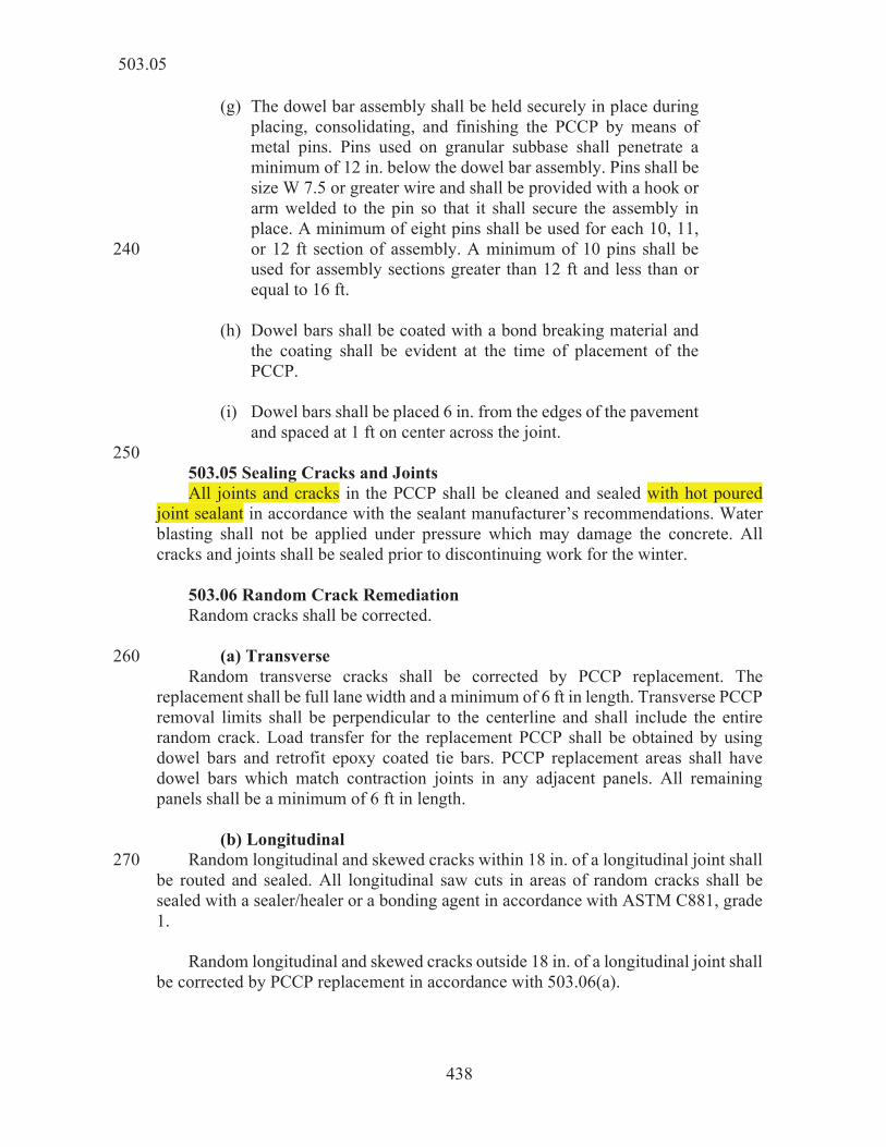
438
(g) The dowel bar assembly shall be held securely in place during placing, consolidating, and finishing the PCCP by means of metal pins. Pins used on granular subbase shall penetrate a minimum of 12 in. below the dowel bar assembly. Pins shall be size W 7.5 or greater wire and shall be provided with a hook or arm welded to the pin so that it shall secure the assembly in place. A minimum of eight pins shall be used for each 10, 11, or 12 ft section of assembly. A minimum of 10 pins shall be 240 used for assembly sections greater than 12 ft and less than or equal to 16 ft.
(h) Dowel bars shall be coated with a bond breaking material and
the coating shall be evident at the time of placement of the PCCP.
(i) Dowel bars shall be placed 6 in. from the edges of the pavement
and spaced at 1 ft on center across the joint. 250 503.05 Sealing Cracks and Joints All joints and cracks in the PCCP shall be cleaned and sealed with hot poured joint sealant in accordance with the sealant manufacturer’s recommendations. Water blasting shall not be applied under pressure which may damage the concrete. All cracks and joints shall be sealed prior to discontinuing work for the winter. 503.06 Random Crack Remediation Random cracks shall be corrected. (a) Transverse 260 Random transverse cracks shall be corrected by PCCP replacement. The replacement shall be full lane width and a minimum of 6 ft in length. Transverse PCCP removal limits shall be perpendicular to the centerline and shall include the entire
e replacement PCCP shall be obtained by using dowel bars and retrofit epoxy coated tie bars. PCCP replacement areas shall have dowel bars which match contraction joints in any adjacent panels. All remaining panels shall be a minimum of 6 ft in length. (b) Longitudinal Random longitudinal and skewed cracks within 18 in. of a longitudinal joint shall 270 be routed and sealed. All longitudinal saw cuts in areas of random cracks shall be sealed with a sealer/healer or a bonding agent in accordance with ASTM C881, grade 1. Random longitudinal and skewed cracks outside 18 in. of a longitudinal joint shall be corrected by PCCP replacement in accordance with 503.06(a).
503.05

439
503.07 Method of Measurement D-1 contraction joints, expansion joint with load transfer, and terminal joints will be measured by the linear foot as measured along the centerline of the joint. The 280 sleeper slab, reinforcing bars, bond breaker, sealants for the terminal joint will not be measured. When required, removal of an existing terminal joint or sleeper slab will not be measured. JRCP will be measured by the square yard of the thickness specified. Reinforcing bars, the metal chairs, spacers, clips, wire, or other mechanical means used for fastening or holding reinforcement in place in the JRCP will not be measured. Pre-compressed foam joints will not be measured. 290 Retrofitted tie bars will be measured by the number of units installed. 503.08 Basis of Payment D-1 contraction joints, expansion joint with load transfer, and terminal joints will be paid for at the contract unit price per linear foot, complete in place. JRCP will be paid for at the contract unit price per square yard of the thickness specified, complete in place. Retrofitted tie bars will be paid for at the contract unit price per each, complete in 300 place. Payment will be made under: Pay Item Pay Unit Symbol D-1 Contraction Joint ................................................................ .......................................... Jointed Reinforced Concrete Pavement, ____ in. ..................... SYS thickness 310 Retrofitted Tie Bars ................................................................... EACH Terminal Joint, Type _______................................................... The cost of furnishing and placing all materials, not specified as a pay item, shall be included in the cost of PCCP. The cost of reinforcing bars, metal chairs, spacers, clips, wire, or other mechanical means used for fastening or holding reinforcement in place shall be included in the cost of the JRCP. 320 For D-1 contraction joints, the cost of dowels, dowel bar assemblies, backer rod, joint sealants and all necessary incidentals shall be included in the cost of D-1 contraction joints.
503.08

440
For the construction of expansion joints, the cost of dowels, dowel bar assemblies, expansion caps, joint filler, joint sealants and all necessary incidentals shall be included in the cost of the expansion joint with load transfer. The cost of the sleeper slab, reinforcing bars, bond breaker, pre-compressed foam joint, joint sealant and all necessary incidentals shall be included in the cost of the 330 terminal joint. When required, removal of an existing terminal joint and sleeper slab shall be included in the cost of the terminal joint. The cost of retrofitted tie bars or PCCP replacement used to repair damaged PCCP due to fault or negligence, remediation of random cracking, or the replacement of broken deformed bars shall be included in the cost of the PCCP.
SECTION 504 – PCCP FINISHING AND CURING 504.01 Description All PCCP surfaces shall be finished and cured in accordance with the following.
MATERIALS 504.02 Materials The materials shall be in accordance with the following: 10 Curing Materials ................................................................. 912.01
CONSTRUCTION REQUIREMENTS 504.03 Finishing PCCP shall be finished with equipment in accordance with 508.04. The operations
handled floats may be used to smooth and fill in open textured areas in the PCCP. Hand methods of finishing may be used when finishing equipment breaks down 20 or in tight working areas where field conditions limit the use of mechanical devices. Hand placed concrete shall be further finished by means of a longitudinal float or an approved transverse smoothing float in accordance with 508.08(a). The edges of formed PCCP adjacent to HMA or compacted aggregate shall be tooled. A continuous radius with a uniform smooth dense mortar finish shall be produced. The PCCP surface shall be textured with a double thickness burlap drag or a minimum 4 ft wide turf drag. 30
504.01

441
The textured surface of PCCP shall be tined, unless otherwise specified. Tining shall consist of transverse grooves that are between 3/32 and 1/8 in. in width, between 1/8 and 3/16 in. in depth, and be spaced as follows: 5/8 in., 1 in., 7/8 in., 5/8 in., 1 1/4 in., 3/4 in., 1 in., 1 in., 1 in., 1 in., 3/4 in., 7/8 in., 1 3/4 in., 7/8 in., 3/8 in., 1 in., 1 in., 1 1/4 in., 1 1/2 in., 7/8 in., 3/4 in., 7/8 in., 1 in., 7/8 in., 1 in. The grooving pattern shall be repeated across the pavement. The grooves shall be formed in the plastic concrete without tearing the surface and without bringing pieces of the coarse aggregate to the top of the surface. 40 Texturing and curing operations may be performed by a single machine subject to satisfactory performance. Areas of PCCP which are not finished in accordance with these requirements shall be corrected by retexturing. Retexturing shall consist of cutting longitudinal or transverse grooves in the PCCP surface by means of saw blades or other approved devices. The grooves shall be spaced 3/4 in. center to center and be 1/8 in. in width and depth. Alternative patterns may be used, subject to approval. The PCCP surface, after cutting, shall not be polished. 50 504.04 Curing Curing materials shall be applied to exposed surfaces and sides of newly placed PCCP within 30 minutes after the finishing operations have been completed, or as soon as marring of the concrete does not occur. Paving operations shall be immediately suspended if sufficient curing materials are not available on site. When forms are used, the edges of the pavement shall be cured immediately upon removal of the forms. The edge shall be covered with curing materials equal to the material used on the surface or banked with soil 12 in. wide or greater. 60 When conditions arise which prevent immediate application of curing materials, the paving operation shall be suspended and the PCCP shall be kept wet with a fine spray of water. The fine spray of water shall continue until application of curing materials resumes. When blended portland pozzolan cements, fly ash, or slag cement are used in the concrete mix, the average ambient temperature must be above 50°F for the curing period. The average temperature shall be calculated based on hourly temperature measurements taken at the jobsite or from published weather station data within 10 70 miles of the jobsite. If the temperature restrictions are not met during placement or during the required curing period, curing shall continue and the PCCP shall not be opened to traffic until the strength requirements are met. If liquid membrane forming compounds are used as the curing method and open to traffic strength has been achieved, the road may be opened to traffic and the 96 h stipulation stated below will not apply. Except when liquid membrane forming
504.04

442
compounds are used, curing shall be continuous for 96 h unless a longer period is ordered. Curing shall be in accordance with the following. 80 (a) Liquid Membrane Forming Compounds The curing compound shall be mixed thoroughly within 1 h before use. The rate of application shall be as approved, with a minimum spreading rate per application of 1 gal. of liquid coating for 150 sq ft of concrete surface. Curing compound shall be applied to provide a uniform, solid, white opaque coverage on all surfaces, similar to a white sheet of paper. All concrete cured by this method shall receive two applications of the curing compound. The first application shall be applied immediately after surface water has disappeared and surface texturing has been applied. If formwork has been used, both applications of curing compound 90 shall be applied immediately after the formwork is removed. The second application shall be applied after the first application has set. The curing compound may be warmed in a water bath during cold weather at a temperature not exceeding 100°F. Thinning with solvents will not be allowed. Non-uniform film rates will result in the discontinuance of that application method. A new coat of curing compound shall be applied to areas damaged by rain or other means during the curing period. The recoating shall be applied as soon as possible and at a rate equal to that specified for the original coat. 100 (b) Double Burlap The PCCP shall be covered with wet burlap, laid directly on the surface, and kept wet with a fine spray of water. This initial burlap shall receive an additional covering of wet burlap no later than 9:00 a.m. the day following its placement. The two layers of burlap shall be kept wet for the required curing period. (c) Waterproof Covers The PCCP shall be kept wet with a fogged spray of water, or be covered with wet burlap laid directly on the surface and kept wet with a fine spray of water. The PCCP 110 shall receive a cover no later than 9:00 a.m. the day following its placement. If white burlap polyethylene sheets are used, the burlap side shall be wet or the surface of the concrete thoroughly wetted just prior to the blanket being placed. The covers shall be weighted down on each edge and shall be as wide as the full width of the pavement being cured. Adjoining covers shall overlap 12 in. or more and the laps held securely in place. Covers may be reused provided they are airtight. All torn covers shall be repaired with patches. All units not in accordance with these requirements shall not be used. 120 The covers shall remain in place for the required curing period.
504.04

443
504.05 Method of Measurement Finishing and curing operations will not be measured for payment. 504.06 Basis of Payment The cost of finishing and furnishing and placing curing materials shall be included in the cost of the PCCP. 130
SECTION 505 – TESTS AND PROCEDURES 505.01 Test Methods and Procedures The following test methods and procedures shall be used with exceptions as listed below. Air Test .......................................................................... AASHTO T 152* or ASTM C173** Flexural Strength ........................................................... AASHTO T 97* Making and Curing Specimens ...................................... AASHTO T 23* 10 Sampling Fresh Concrete .............................................. AASHTO R 60 Sieve Analysis of Aggregates ........................................ AASHTO T 27 Slump ............................................................................ AASHTO T 119 Specific Gravity and Absorption, Coarse Aggregate ..... AASHTO T 85 Specific Gravity and Absorption, Fine Aggregate ......... AASHTO T 84 Thickness of PCCP ........................................................ ITM 404 Unit Weight and Relative Yield .................................... AASHTO T 121* Water/Cementitious Ratio ............................................. ITM 403 * The concrete shall be consolidated by the method of internal 20
vibration in beam forms or in an aluminum measure or air meter bowl, as appropriate for the test.
** If slag aggregate is used, the method and procedure for the test shall
be in accordance with ASTM C173. The chosen method of concrete consolidation shall be the same for all concrete test specimens. (a) Exceptions to AASHTO T 23 30 The exceptions to AASHTO T 23 for making and curing specimens in the field shall be as follows: 1. Non-watertight beam forms, molds, will be allowed. 2. After 24 h the molded specimens are taken to the storage
location and removed from the molds. 3. Field stored beams will not require 24 ±4 h lime water soak
prior to time of testing. 40
505.01

444
(b) Exceptions to AASHTO T 97 The exceptions to AASHTO T 97 for conducting a flexural test on concrete beams shall be as follows: 1. The beam size shall be measured to the nearest 1/16 in. 2. The test result shall be discarded when the break occurs
outside the middle 1/3 of the beam. 50 (c) Exceptions to AASHTO T 121 The exceptions to AASHTO T 121 for determining the unit weight of concrete shall be as follows: 1. Weight shall be determined to the nearest 0.01 lb. (d) Exceptions to AASHTO R 60 The exceptions to AASHTO R 60 for sampling fresh concrete shall be as follows: 1. Where job conditions dictate, the entire sample may be 60
obtained from one portion of the load. (e) Exceptions to AASHTO T 152 The exceptions to AASHTO T 152 for determining the air content in portland cement concrete shall be as follows: 1. The sample for aggregate correction factor shall be
prepared in accordance with 6.0. The aggregate correction factor shall be determined in accordance with 8.3 and read directly from the meter. 70
2. The aggregate correction factor test shall be re-run for
confirmation if the test results for gravel is greater than 0.4% or if the test results for crushed stone is greater than 0.6%.
3. For aggregates indicating a high correction factor, the
aggregate may be washed from the concrete sample and used to determine the correction factor.
80
SECTION 506 – PCCP PATCHING 506.01 Description This work shall consist of the removal and replacement of jointed plain PCCP or jointed reinforced PCCP in accordance with 105.03.
506.01

445
MATERIALS 506.02 Materials Materials shall be in accordance with the following: 10 Admixtures ......................................................................... 912.03 .................................................. 913.02 Chemical Anchor System ................................................... 901.05 Coarse Aggregate, Class A or Higher, Size No. 11 ............ 904.03 Concrete Coarse Aggregate, Class AP ............................... 904.03, ITM 226 Dowel Bar Assemblies ....................................................... 503.04 Dowel Bars ......................................................................... 910.01(b)10 Fine Aggregate, Size No. 23 ............................................... 904.02 Fly Ash ............................................................................... 901.02 20 Joint Fillers ......................................................................... 906.01A Joint Sealing Materials ....................................................... 906.02(a)2 Portland Cement ................................................................. 901.01(b) Rapid Hardening Hydraulic Cement .................................. 901.01(d) Silica Fume ......................................................................... 901.04 Slag Cement ....................................................................... 901.03 Water .................................................................................. 913.01 A A flexible foam expansion joint material meeting the
requirements of ASTM D5249, type 2 may also be used for the 30 retrofit pressure relief joint. If the flexible foam expansion joint is used, the basis for use will be a type C certification in accordance with 916.
Coarse aggregate for partial depth patching shall be size No. 11. Coarse aggregate for full depth patching shall be size No. 8. Coarse aggregate for patches shall be dolomite, limestone, or gravel. Retrofitted tie bars shall be No. 5 or No. 6 epoxy coated reinforcing bars in accordance with 910.01(b)9. 40 The rapid hardening hydraulic cement or calciumsulfoaluminate, CSA, cement type selected shall be a type shown in ASTM C1600 that will enable opening to traffic in accordance with the contract requirements. Food grade citric acid may be used as an organic retarding admixture in concrete utilizing CSA cement. The use and strength of food grade citric acid, or any other admixture, shall be approved in writing by the manufacturer of the CSA cement. The basis for use for the food grade citric acid will be visual inspection. A bonding agent shall be selected from the of Non-Vapor Barrier Type 50 Bonding Agents.
506.02

446
506.03 Concrete Mix Design A concrete mix design submittal, CMDS, shall be in accordance with 506.04. The CMDS shall be submitted to the DTE. The CMDS shall be submitted a minimum of seven calendar days prior to the trial batch. The CMDS shall use the Department provided spreadsheet and shall include the following: (a) a list of all ingredients, including the type of CSA
cement, if applicable 60 (b) the source of all materials (c) the fine to total aggregate ratio (d) the absorption of the aggregates (e) the SSD bulk specific gravity of the aggregates (f) the specific gravity of pozzolan (g) the batch weights (h) the names of all admixtures (i) the admixture dosage rates and the manufacturer’s
recommended range. 70 The aggregate blend submitted on the CMDS shall produce an optimized aggregate gradation in accordance with ITM 226, sections 6.2.1 and 6.3. The aggregate blend shall consist of, at a minimum, one Concrete Coarse Aggregate and one fine aggregate, No. 23. One additional class A or higher intermediate-sized coarse aggregate may be included if approved by the Engineer. The absolute volume of the mix design shall be 27.0 cu ft at the design air content of 6.5%. The CMDS shall be used to conduct a trial batch in accordance with 506.05. Upon 80 completion of the trail batch, the Contractor shall submit the CMDS and the Contractor’s and the Engineer’s trial batch results for the CMDS to the DTE. The results shall be submitted to the DTE utilizing the Department furnished spreadsheet a minimum of three work days prior to production. Production shall not commence until the DTE has assigned a mix number to the CMDS. The concrete mix design will henceforth be identified as a concrete mix design for production, CMDP. A CMDP from another contract in the current or previous calendar year may be submitted for review for use on the current contract to the DTE. The DTE will notify the Contractor when the review is complete and whether or not the previously used 90 CMDP can be used on the current contract. A CMDP may be changed or adjusted in accordance with the following: (a) Change in Materials A change in a previously approved CMDP, for a given contract, to any of the following shall be submitted to the DTE as a CMDS, referencing the original CMDP.
506.03

447
1. cement source or type 2. pozzolan source or type 100 3. coarse aggregate source or type 4. admixture type. A trial batch shall be conducted in accordance with 506.05. (b) Adjustments to Materials An adjustment in a previously approved CMDP, for a given contract, to any of the following shall be submitted to the DTE as a CMDS, referencing the original CMDP. 110 1. admixture source 2. admixture product of same type and from same source
designated in the original CMDP 3. fine aggregate source 4. fine to total aggregate ratio in excess of ±3% from the value
designated by the original CMDP 5. Increase in cement content from amount designated in the
original CMDP. The new CMDS shall be submitted to the DTE utilizing the Department 120 spreadsheet a minimum of one work day prior to production. A trial batch or verification testing is not required for approval. Production shall not commence without an approved CMDP. (c) Other Adjustments Other adjustments in previously approved CMDP, for a given contract, to the admixture dosage rate will be allowed and DTE notification and review prior to use is not required. 506.04 Concrete Mix Criteria 130 The design flexural strength of each CMDP shall be set such that the minimum opening to traffic strength is achieved at an age consistent with the work schedule, including any lane closure restrictions. Chemical admixtures type A, type B, type C, type D, type E, and type F may be allowed if shown on the CMDP. The supplied concrete mix shall include one of the following water reducing admixtures: type A, type D, type E, type F, or type G.
d in mixes 140 for non-reinforced PCCP and for mixes in accordance with 506.04(a). Blended portland pozzolan cements, fly ash, or slag cement may only be incorporated in the concrete mix when the ambient temperature is above 50°F during
506.04

448
the entire placement period. If type IP, type IP-A, type IS or type IS-A cements are to be used, the minimum portland cement content shall be increased to 598 lb/cu yd. The use of fly ash or slag cement will not be allowed when blended cement types IP, IP-A, IS, or IS-A are used. The Contractor may use either portland cement or CSA cement in the concrete. 150 Fly ash or slag cement may also be used. If concrete has a permeability of 900 coulombs or less at 56 days, the acceptable range of air content will be 0 - 6.0%. Verification of this property for a mix design will be determined by testing specimens cast at the trial batch. Testing will be done per AASHTO T 23 Section 10.1 Standard Cure conditions. The CMD shall produce workable concrete mixtures having the following targets and field acceptance properties. 160 (a) Patches Less than or Equal to 15 ft in Length The Contractor shall use either concrete as described below or concrete in accordance with 506.04(b). If concrete in accordance with 506.04(b) is used, 506.12(b) shall be used for the minimum open to traffic strength. Targets for the CMD: Minimum portland cement content ..................................... 564 lb/cu ydA Maximum portland cement content .................................... 752 lb/cu ydA Minimum CSA cement content .......................................... 564 lb/cu ydA, B 170 Maximum CSA cement content ......................................... 658 lb/cu ydA, B ............. 0.340C ............ 0.400C Minimum water/cementitious ratio (type III or CSA) ........ 0.340C Maximum water/cementitious ratio (type III or CSA) ....... 0.435C Maximum fly ash or slag cement addition ......................... 30% of the cement contentB Maximum silica fume addition ........................................... 7% of the cementitious content Air Content ......................................................................... 6.5% 180 Minimum modulus of rupture............................................. 400 psi at 24 h Minimum modulus of rupture............................................. 550 psi at 3 daysD Relative Yield ..................................................................... 1.00 Field Acceptance Properties: ............. 0.320C ............ 0.420C Minimum water/cementitious ratio (type III or CSA) ........ 0.340C Maximum water/cementitious ratio (type III or CSA) ....... 0.450C 190
506.04

449
Slump ................................................................................. 2 to 6 in. Air Content ......................................................................... 5.0% to 8.0% Minimum modulus of rupture............................................. 550 psi at 3 daysD Relative Yield ..................................................................... 0.98 to 1.02
A The cement content shall not be adjusted from the target stated on the CMDP during production.
B Fly ash or slag cement shall not be used in combination with CSA
cement unless approved in writing by the manufacturer of the CSA 200 cement.
C The water/cementitious ratio shall not deviate more than 0.020 from
the target stated in the CMDP and shall not fall outside the limits shown.
D Beams shall be standard cured in a water tank in accordance with
AASHTO T 23 and 505.01(a). The water does not need to be saturated with calcium hydroxide.
210 When a calcium chloride solution is added, the maximum amount of solid calcium chloride contained in solution shall not exceed 2%, of the total batch weight of cement. If the ambient temperature is above 80°F, the maximum amount of solid calcium chloride contained in solution shall not exceed 1% of the total batch weight of cement. (b) Patches Greater than 15 ft in Length The Contractor shall use either concrete as described below, or portland cement concrete in accordance with 502.04(a). If concrete in accordance with 502.04(a) is used, a trial batch will not be required. 220 Targets for the CMD: ....... 564 lb/cu ydA ...... 752 lb/cu ydA Minimum CSA cement content .......................................... 564 lb/cu ydA, B Maximum CSA cement content ......................................... 658 lb/cu ydA, B ............. 0.340C ............ 0.400C Minimum water/cementitious ratio (type III or CSA) ........ 0.340C Maximum water/cementitious ratio (type III or CSA) ....... 0.435C 230 Maximum fly ash or slag cement addition ......................... 30% of the cement contentB Maximum silica fume addition ........................................... 7% of the cementitious content Air Content ......................................................................... 6.5% Minimum modulus of rupture............................................. 425 psi at 24 h Minimum modulus of rupture............................................. 550 psi at 3 daysD Relative Yield ..................................................................... 1.00
506.04

450
Field Acceptance Properties: 240 ............. 0.320C ............ 0.420C Minimum water/cementitious ratio (type III or CSA) ........ 0.340C Maximum water/cementitious ratio (type III or CSA) ....... 0.450C Slump ................................................................................. 2 to 6 in. Air Content ......................................................................... 5.0% to 8.0% Minimum modulus of rupture............................................. 550 psi at 3 daysD Relative Yield ..................................................................... 0.98 to 1.02 250
A The target cement content during production shall not be adjusted from the value stated on the CMDP.
B Fly ash or slag cement shall not be used in combination with CSA
cement unless approved in writing by the manufacturer of the CSA cement.
C The water cementitious ratio during production shall not deviate more
than 0.020 from the target stated in the CMDP and shall not fall outside the limits above. 260
D Beams shall be standard cured in a water tank in accordance with
AASHTO T 23 and 505.01(a). The water does not need to be saturated with calcium hydroxide.
506.05 Trial Batch A trial batch shall be produced and tested by the Contractor’s certified technician to verify that the CMDS is in accordance with the concrete mix criteria. Concrete produced at a plant shall be batched within the proportioning tolerances of 502.10. An American Concrete Institute certified concrete field testing technician, grade 1 shall 270 be on site to direct all sampling and testing. The trial batch shall be produced at the plant prior to production. A sufficient number of flexural strength test beams shall be made and will be tested to demonstrate that opening to traffic strength is achieved at an age consistent with the proposed range of usage of the mixture. At a minimum, flexural strength gain will be determined at the target opening to traffic times and at the specified 24 h and 3 day targets as specified by the respective mix criteria. The Engineer will test the concrete’s air content and determine the water/cementitious ratio, and prepare and test flexural beams. The flexural strength will be determined by averaging a minimum of 280 two beam breaks. The Department will provide the apparatus to test the beams for flexural strength. Personnel shall be provided to assist the Department in casting, curing, and testing the beams. The Engineer will provide the Contractor the results of the tests. The Contractor shall submit, along with the CMDS, all supporting test results for approval
506.05

451
to the DTE prior to placing concrete. The supporting test results shall be signed by the technician and include air content, slump, relative yield, water/cementitious ratio, and the flexural strengths at the targets listed in 506.04(a) or 506.04(b). 290 Maturity in accordance with ITM 402 may be used as an alternate method to determine the flexural strength for opening to traffic. A trial batch will not be required when the total quantity of full depth patching requires less than 10 cu yds of material per contract. The trial batch shall be of sufficient quantity to allow the Engineer to perform all required tests from the same batch. Trial batch concrete shall not be used for more than one test, except concrete used to measure relative yield may also be used to measure air content. 300 506.06 Job Control Control of PCCP for air content, relative yield, and flexural strength beams will be determined on the basis of tests performed by the Engineer in accordance with 505. Concrete and necessary labor for sampling shall be furnished as required by the Engineer. Testing for air content and relative yield will be on the first load of the day and once per every 50 cu yds. (a) Beams for Validation of CMDP At least one set, consisting of three beams per set, will be made once per every 310 150 cu yds of concrete placed and tested for compliance with either the 3 day or 7 day flexural strength requirements in accordance with 506.04, for the purpose of CMDP validation. Air content and relative yield will be measured on each sample of concrete from which beams are made. Beams for validation shall be placed on the concrete pavement or shoulder adjacent to the patch and cured in a similar manner as the patch in accordance with 505.01(a) until patch area is open to traffic. At which point the beams shall be relocated off-site and standard cured in accordance with AASHTO T 23, Section 10.1.2 with the exception that the water does not need to be saturated with calcium hydroxide until the 320 3 or 7 day time period has elapsed. Failure of the validation beams to meet or exceed the 3-day or 7-day flexural strength requirements specified herein will result in the use of the CMDP being suspended until the Department concludes an investigation into why the failure occurred. If the CMDP is subsequently shown to be acceptable, another set of validation beams will be tested on the next use of the CMDP. (b) Beams for Opening to Traffic Additional beams shall be cast for the purpose of opening to traffic for concrete 330 meeting the requirements of 506.04(a) or 506.04(b). Such beams shall be cast from sampling the last load to finish the patching operations for the day’s production for
506.06
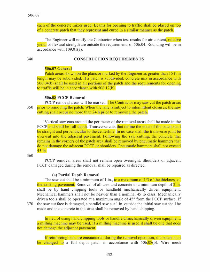
452
each of the concrete mixes used. Beams for opening to traffic shall be placed on top of a concrete patch that they represent and cured in a similar manner as the patch. The Engineer will notify the Contractor when test results for air content, relative yield, or flexural strength are outside the requirements of 506.04. Rounding will be in accordance with 109.01(a).
CONSTRUCTION REQUIREMENTS 340 506.07 General Patch areas shown on the plans or marked by the Engineer as greater than 15 ft in length may be subdivided. If a patch is subdivided, concrete mix in accordance with 506.04(b) shall be used in all portions of the patch and the requirements for opening to traffic will be in accordance with 506.12(b). 506.08 PCCP Removal PCCP removal areas will be marked. The Contractor may saw cut the patch areas prior to removing the patch. When the lane is subject to intermittent closures, the saw 350 cutting shall occur no more than 24 h prior to removing the patch. Vertical saw cuts around the perimeter of the removal areas shall be made in the PCCP and shall be full depth. Transverse cuts that define the ends of the patch shall be straight and perpendicular to the centerline. In no case shall the transverse joint be over-cut into the adjacent pavement. Following the saw cutting, the concrete that remains in the corners of the patch area shall be removed by pneumatic hammers that do not damage the adjacent PCCP or shoulders. Pneumatic hammers shall not exceed 45 lb. 360 PCCP removal areas shall not remain open overnight. Shoulders or adjacent PCCP damaged during the removal shall be repaired as directed. (a) Partial Depth Removal The saw cut shall be a minimum of 1 in., to a maximum of 1/3 of the thickness of the existing pavement. Removal of all unsound concrete to a minimum depth of 2 in. shall be by hand chipping tools or handheld mechanically driven equipment. Mechanical hammers shall not be heavier than a nominal 45 lb class. Mechanically driven tools shall be operated at a maximum angle of 45° from the PCCP surface. If the saw cut face is damaged, a parallel saw cut 1 in. outside the initial saw cut shall be 370 made and the concrete in this area shall be removed by hand chipping. In lieu of using hand chipping tools or handheld mechanically driven equipment, a milling machine may be used. If a milling machine is used it shall be one that does not damage the adjacent pavement. If reinforcing bars are encountered during the removal operation, the patch shall be changed to a full depth patch in accordance with 506.08(b). Wire mesh
506.07

453
reinforcement exposed during the removal operations shall be removed. 380 If concrete is exposed below 1/3 of the thickness of the existing pavement, the patch shall be changed to a full depth patch in accordance with 506.08(b). Partial depth cavities shall be thoroughly sandblasted and, just prior to placing new concrete, cleaned of all dust, chips, and water. The air lines for sandblasting and air cleaning shall be equipped with oil traps to prevent contamination of the surfaces. (b) Full Depth Removal After the full depth saw cut is completed, vehicle mounted removal equipment may be used to remove the concrete provided this equipment does not damage the 390 adjacent sound concrete. Removal areas in the same lane which are closer than 10 ft shall require the PCCP between these areas to be removed and replaced. If a transverse joint is located within the removal area, the limits of removal shall be as shown on the plans. Full depth saw cutting and removal shall be extended at the direction of the Engineer until sound PCCP is encountered to allow the drilling and installation of dowel bars for load transfer, without inflicting further damage to the existing PCCP. Removal operations shall not damage the existing PCCP that is sound and is to remain 400 in place. Existing subbase shall be completely removed. Before removing any type of asphalt treated, cement treated or concrete subbase, the Contractor shall saw cut the outline of the removal area using a power-driven saw with a diamond blade. The Contractor shall cut the asphalt treated subbase at least 2 in. deep on a neat line perpendicular to the subbase surface. The Contractor shall cut the cement treated subbase or concrete subbase full depth. 506.09 Concrete Mixing and Transportation 410 (a) For Patches Less than or Equal to 15 ft in Length Concrete batching tolerances, mixing, and transportation shall be in accordance with 502.10 and the following. Discharge from non-agitating equipment shall be completed within 30 minutes of mixing the water, cement, aggregates, and calcium chloride solution. Discharge from a truck agitator or a truck mixer shall be completed within 90 minutes of mixing the water, cement, and aggregates or within 30 minutes of the addition of calcium chloride solution. If the location of the plant is such that this time limit cannot be met, the calcium chloride solution shall be added to the concrete in a transit mixer at the site and the concrete shall then be mixed for an additional 40 420 revolutions prior to discharge. 1. Central Mixed Concrete Central mixed concrete shall be in accordance with 502.10(a).
506.09

454
2. Shrink Mixed Concrete Shrink mixed concrete shall be in accordance with 502.10(b). 3. Transit Mixed Concrete Transit mixed concrete shall be in accordance with 502.10(c). 430 (b) For Patches Greater than 15 ft in Length For patches containing portland cement, the mixing and transportation shall be in accordance with 502.10. If concrete containing CSA cement is used, it may be batched and mixed in a mobile volumetric mixer meeting the requirements of 722.09, regardless of the patch length. Calibration of the mobile mixer shall be in accordance with 722.13. Alternatively, a mixer from a CSA cement supplier may be used, contingent upon approval by the Engineer. 506.10 Weather Limitations 440 PCCP patches shall not be placed on frozen subgrade, subbase, or PCCP. 506.11 Placing Concrete The concrete shall be placed level to the adjacent PCCP and consolidated by internal vibration. The concrete shall be hand finished in accordance with 504. Texturing and tining are not required if the PCCP is to be resurfaced with HMA or diamond ground in accordance with 507.06. The PCCP patch shall be cured with liquid membrane forming curing compound in accordance with 504.04(a). In addition to applying liquid membrane forming curing 450 compound, if the ambient temperature is below 55°F at the time of placement, polyethylene film shall be placed over the patch and covered with a 4 in. layer of rigid or flexible insulation and firmly anchored. Otherwise, polyethylene film, insulation, or any other covering shall not be used. Small dimension lumber weighted with sandbags may be used, but large objects such as rocks or concrete blocks shall not be used. Covering with polyethylene film or any other covering does not replace the requirement to use liquid membrane forming curing compound. 460 The PCCP patch shall be inspected in accordance with 502.17. For patches which are not to be overlaid and have a length greater than 20 ft, pavement smoothness will be in accordance with 501.25 except profilograph requirements will not apply. (a) Partial Depth A non-vapor barrier type bonding agent shall be applied to the vertical and horizontal surfaces prior to placing concrete. Coated surfaces shall be protected from contaminants such as dust and dirt. Contaminated surfaces shall be recleaned and 470 recoated. The bonding agent and concrete shall be placed in accordance with the
506.10

455
bonding agent manufacturer’s recommendations. The recommended time limits will be strictly enforced. Existing joint openings within the patch shall be maintained for the full depth of the patch by preformed joint fillers or forms. After the patch has cured, these joints shall be sawe–d and sealed in accordance with 503. (b) Full Depth Subgrade treatment and subbase shall be constructed as shown on the plans. 480 Dowel bars shall be installed to provide load transfer from the adjoining PCCP to the patch. The diameter of the drilled holes shall be no more than 1/8 in. greater than the diameter of the dowel bar. Dowel bars shall be placed parallel to the pavement surface and to the longitudinal joint. Dowel alignment tolerances shall be as shown on the plans. Dowel holes shall be drilled using hydraulic, electric, or pneumatic percussion drills without spalling or damaging the existing concrete. Drills shall be capable of independent adjustment of each drill shaft in the horizontal and vertical direction. The 490 device used to drill dowel holes shall be slab-riding and be capable of drilling a minimum of three holes at a time. The drilled holes shall be free of dust, moisture, and grease prior to installation of the dowel bars. The chemical anchor system shall be injected to the back of the hole to eliminate air pockets prior to inserting the dowel bar. The quantity of material injected shall be sufficient to disperse the chemical anchor material along the entire length of the dowel bar and completely fill all voids around the bar. Application of the chemical anchor system by buttering it onto the dowel bar will not be allowed. 500 After the anchor system has been injected, the dowel bar shall be fully inserted in the hole using a back-and-forth twisting motion, leaving the proper length exposed. If it is necessary to use a hammer to seat the dowel bar, the exposed end shall be protected with a wood block. A lightweight plastic, clear or semi-transparent grout retention ring shall be installed after each dowel bar is inserted into the hole. The grout retention ring shall be pushed flush to the vertically sawn concrete surface and shall be used to help retain the chemical anchor system in the dowel hole. 510 Retrofit tie bars shall be installed in accordance with 503 and as shown on the plans. The tolerance for horizontal and vertical translation shall be the same as for dowel bars. Joint filler and grout retention rings shall be placed and installed at the pressure relief joint as shown on the plans. Oversized holes shall be drilled in the joint filler no
506.11
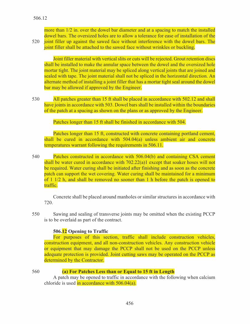
456
more than 1/2 in. over the dowel bar diameter and at a spacing to match the installed dowel bars. The oversized holes are to allow a tolerance for ease of installation of the joint filler up against the sawed face without interference with the dowel bars. The 520 joint filler shall be attached to the sawed face without wrinkles or buckling. Joint filler material with vertical slits or cuts will be rejected. Grout retention discs shall be installed to make the annular space between the dowel and the oversized hole mortar tight. The joint material may be spliced along vertical joints that are joined and sealed with tape. The joint material shall not be spliced in the horizontal direction. An alternate method of installing a joint filler that has a mortar tight seal around the dowel bar may be allowed if approved by the Engineer. All patches greater than 15 ft shall be placed in accordance with 502.12 and shall 530 have joints in accordance with 503. Dowel bars shall be installed within the boundaries of the patch at a spacing as shown on the plans or as approved by the Engineer. Patches longer than 15 ft shall be finished in accordance with 504. Patches longer than 15 ft, constructed with concrete containing portland cement, shall be cured in accordance with 504.04(a) unless ambient air and concrete temperatures warrant following the requirements in 506.11. Patches constructed in accordance with 506.04(b) and containing CSA cement 540 shall be water cured in accordance with 702.22(a)1 except that soaker hoses will not be required. Water curing shall be initiated after finishing and as soon as the concrete patch can support the wet covering. Water curing shall be maintained for a minimum of 1 1/2 h, and shall be removed no sooner than 1 h before the patch is opened to traffic. Concrete shall be placed around manholes or similar structures in accordance with 720. Sawing and sealing of transverse joints may be omitted when the existing PCCP 550 is to be overlaid as part of the contract. 506.12 Opening to Traffic For purposes of this section, traffic shall include construction vehicles, construction equipment, and all non-construction vehicles. Any construction vehicle or equipment that may damage the PCCP shall not be used on the PCCP unless adequate protection is provided. Joint cutting saws may be operated on the PCCP as determined by the Contractor. (a) For Patches Less than or Equal to 15 ft in Length 560 A patch may be opened to traffic in accordance with the following when calcium chloride is used in accordance with 506.04(a).
506.12

457
T H HT T H HT 40 - 42°F 30 26 61 - 63°F 14 9 43 - 45°F 27 23 64 - 66°F 14 9 46 - 48°F 24 21 67 - 69°F 14 8 49 - 51°F 21 19 70 - 72°F 14 7 52 - 54°F 19 16 73 - 75°F 14 6 55 - 57°F 16 14 above 75°F 14 5 58 - 60°F 16 11
T = placement, or the temperature of concrete at time of delivery, whichever is lower
H = Time in hours to open to traffic HT = Time in hours to open to traffic when the average daily traffic is
less than 10,000
PCCP patches with calcium chloride may be opened to traffic sooner than specified in the above table if test beams indicate a modulus of rupture of 300 psi or greater. ITM 402 may be used as an alternative method to determine the flexural strength. When other admixtures or admixture systems are used, the PCCP patches may be 570 opened to traffic when flexural strength tests indicate a modulus of rupture of 300 psi or greater. ITM 402 may be used as an alternate method to determine the flexural strength. (b) For Patches Greater than 15 ft in Length Traffic shall not be allowed on the PCCP until a modulus of rupture of 425 psi from flexural strength testing is achieved. The modulus of rupture will be determined by averaging two beams. 506.13 Method of Measurement 580 Partial depth patching and full depth patching will be measured by the square yard. D-1 contraction joints and retrofitted tie bars used in PCCP patching will be measured in accordance with 503.07. When subgrade treatment is specified, it will be measured in accordance with 207.05. New subbase will be measured in accordance with 302.08. PCCP removal, subbase removal, concrete, finishing, curing, and sawing and 590 sealing of joints will not be measured for payment. Retrofit pressure relief joints, retrofit contraction joints, non-vapor barrier bonding agent, anchored dowel bars installed at the beginning and end of the patch, individual dowel bars, joint fillers, joint materials, drilling holes for dowel bars, grout retention rings, and chemical anchor systems will not be measured for payment.
506.13

458
506.14 Basis of Payment PCCP patching will be paid for at the contract unit price per square yard for the type of patching required. 600 D-1 contraction joints and retrofitted tie bars used in PCCP patching will be paid for in accordance with 503.08. Subgrade treatment will be paid for in accordance with 207.06. New subbase will be paid for in accordance with 302.09. Partial depth patches which have been directed to be full depth will be paid for at the contract unit price per square yard for PCCP patching, partial depth, plus 80% of the contract unit price per square yard for PCCP patching, full depth. 610 Payment will be made under: Pay Item Pay Unit Symbol PCCP Patching, Full Depth ....................................................... SYS PCCP Patching, Partial Depth ................................................... SYS The cost of PCCP removal, subbase removal, concrete, finishing and curing, and sawing and sealing of joints shall be included in the cost of PCCP patching. 620 The cost of retrofit pressure relief joints, retrofit contraction joints, non-vapor barrier bonding agent, anchored dowel bars installed at the beginning and end of the patch, individual dowel bars, joint fillers, joint materials, drilling holes for dowel bars, grout retention rings, and chemical anchoring system shall be included in the cost of PCCP patching. The cost of corrections for pavement smoothness and re-texturing shall be included in the cost of PCCP patching. 630 Repair or replacement of adjacent PCCP or shoulder damaged by the Contractor shall be made at no additional cost to the Department.
SECTION 507 – PCCP RESTORATION 507.01 Description This work shall consist of cleaning and sealing of joints and cracks, patching, profiling, underseal, and retrofit load transfer in accordance with 105.03.
MATERIALS 507.02 Materials Materials shall be in accordance with the following: 10
506.14
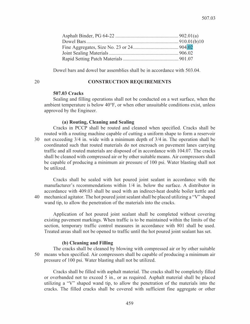
459
Asphalt Binder, PG 64-22 .................................................. 902.01(a) Dowel Bars ......................................................................... 910.01(b)10 Fine Aggregates, Size No. 23 or 24 .................................... 904.02 Joint Sealing Materials ....................................................... 906.02 Rapid Setting Patch Materials ............................................ 901.07 Dowel bars and dowel bar assemblies shall be in accordance with 503.04.
CONSTRUCTION REQUIREMENTS 20 507.03 Cracks Sealing and filling operations shall not be conducted on a wet surface, when the ambient temperature is below 40°F, or when other unsuitable conditions exist, unless approved by the Engineer. (a) Routing, Cleaning and Sealing Cracks in PCCP shall be routed and cleaned when specified. Cracks shall be routed with a routing machine capable of cutting a uniform shape to form a reservoir not exceeding 3/4 in. wide with a minimum depth of 3/4 in. The operation shall be 30 coordinated such that routed materials do not encroach on pavement lanes carrying traffic and all routed materials are disposed of in accordance with 104.07. The cracks shall be cleaned with compressed air or by other suitable means. Air compressors shall be capable of producing a minimum air pressure of 100 psi. Water blasting shall not be utilized. Cracks shall be sealed with hot poured joint sealant in accordance with the manufacturer’s recommendations within 1/4 in. below the surface. A distributor in accordance with 409.03 shall be used with an indirect-heat double boiler kettle and mechanical agitator. The hot poured joint sealant shall be placed utilizing a “V” shaped 40 wand tip, to allow the penetration of the materials into the cracks. Application of hot poured joint sealant shall be completed without covering existing pavement markings. When traffic is to be maintained within the limits of the section, temporary traffic control measures in accordance with 801 shall be used. Treated areas shall not be opened to traffic until the hot poured joint sealant has set. (b) Cleaning and Filling The cracks shall be cleaned by blowing with compressed air or by other suitable means when specified. Air compressors shall be capable of producing a minimum air 50 pressure of 100 psi. Water blasting shall not be utilized. Cracks shall be filled with asphalt material. The cracks shall be completely filled or overbanded not to exceed 5 in., or as required. Asphalt material shall be placed utilizing a “V” shaped wand tip, to allow the penetration of the materials into the cracks. The filled cracks shall be covered with sufficient fine aggregate or other
507.03

460
suitable material to prevent tracking of the asphalt material. All excess cover material shall be removed from the pavement within 24 h, when directed. Application of asphalt material shall be completed without covering existing 60 pavement markings. When traffic is to be maintained within the limits of the section, temporary traffic control measures in accordance with 801 shall be used. Treated areas shall not be opened to traffic until the asphalt material has set. 507.04 Joints Sealing and filling operations shall not be conducted on a wet surface, when the ambient temperature is below 40°F, or when other unsuitable conditions exist, unless approved by the Engineer. (a) Sawing, Cleaning and Sealing 70 Joints in PCCP shall be sawed, cleaned and sealed when specified. Air compressors shall be capable of producing a minimum air pressure of 100 psi. Water blasting shall not be applied under pressure which may damage the concrete. The existing joints shall be sawed to the width and depth as shown on the plans. Slurry or saw residue remaining in the slot shall be immediately flushed with water. Traffic may be allowed on the PCCP for up to seven calendar days after the saw cutting prior to sealing. Joints shall be sealed with joint sealing materials in accordance with the sealant manufacturer’s recommendations. Transverse joints shall be sealed with hot poured 80 joint sealant, silicone sealant or preformed elast nal joints shall be sealed with hot poured joint sealant or silicone sealants. Application of asphalt materials shall be completed without covering existing pavement markings. When traffic is to be maintained within the limits of the section, temporary traffic control measures in accordance with 801 shall be used. Treated areas shall not be opened to traffic until the asphalt material has set. (b) Cleaning and Filling Joints in PCCP shall be cleaned and filled when specified. Cleaning shall include 90 removal of old sealant and backer rod. Air compressors shall be capable of producing a minimum air pressure of 100 psi. Water blasting shall not be utilized. Joints shall be filled with hot poured joint sealant in accordance with the manufacturer’s recommendations within 1/4 in. below the surface. A distributor in accordance with 409.03 shall be used with an indirect-heat double boiler kettle and mechanical agitator. The hot poured joint sealant shall be placed utilizing a “V” shaped wand tip, to allow the penetration of the materials into the joints. 507.05 PCCP Patching 100 (a) Full Depth and Partial Depth Patching PCCP patching shall be in accordance with 506.
507.04

461
(b) Joint Repair PCCP joint repair shall be in accordance with 509. 507.06 Profiling Profiling consists of the diamond grinding of the pavement. The grinding shall be completed by mechanical grinding equipment in accordance with 508.08(c). Grinding 110 shall be completed in a longitudinal direction and shall begin and end at lines normal to the pavement centerline in any ground section. The operation shall be coordinated such that the slurry or residue materials are continuously removed from the pavement. The slurry shall not encroach into adjacent pavement lanes carrying traffic, or flow into gutters or other drainage facilities and shall be immediately and directly deposited into a tanker truck and removed from the jobsite. Final disposal of the material shall be in an approved manner and in accordance with 104.07. Pavement smoothness will be measured and adjusted in accordance with 501.25 and 501.28(d) after the cracks are routed, cleaned, and sealed in accordance with 507.03 and joints are sawed, cleaned, and resealed in accordance with 507.04. 120 507.07 Undersealing Undersealing shall be in accordance with 612. 507.08 Retrofit Load Transfer for PCCP Retrofit load transfer consists of diamond saw slot cutting and placing dowel bar assemblies in the PCCP, parallel to the centerline of the roadway without damaging adjacent PCCP. The diamond-sawed slot shall be cut using two diamond saw blades per slot to cut the edges of the slot. The PCC within the slot and the burrs and bumps remaining in the base of the slots after cutting shall be removed with hand or 130 mechanical chipping hammers which shall not exceed a nominal 15 lb in weight and shall be operated at a maximum angle of 45° from the pavement surface. All surfaces of the slots shall be thoroughly cleaned by sand blasting and all cracks in the slots shall be sealed with a silicone sealer. The slots shall be cleaned and blown dry with compressed air. Dowel bar assemblies shall be as shown on the plans. Prior to placement, the assemblies shall be coated with a bond breaking material and placed on non-metallic supports in the slots. Dowel bars shall be parallel to the pavement surface. 140 Rapid setting patch material shall be mixed and cured in accordance with the manufacturer’s recommendations. The material shall be placed in the slots and troweled to match existing adjoining PCCP. Excess material removed during placing and troweling shall not be reused. Transverse contraction joints with retrofitted load transfers shall be sawed for the full lane width and sealed in accordance with 503.03(a) except the joint shall be cut in one operation. Transverse random cracks with retrofitted load transfer slots shall be routed and sealed for the full lane width in accordance with 503.05. 150
507.08

462
PCCP damaged outside the area of the slots due to the Contractor’s operations shall be repaired in an acceptable manner or replaced. 507.09 Method of Measurement Routing and sealing of cracks, filling of cracks, sawing and sealing of joints, and filling of joints will be measured by the linear foot, complete in place. Retrofit load transfer will be measured by each dowel bar assembly installed, complete in place. PCCP patching will be measured in accordance with 506.13. PCCP joint repair will be measured in accordance with 509.18. Profiling, regardless of depth, will be 160 measured by the square yard. Asphalt material and drilled holes for undersealing will be measured in accordance with 612.07. Construction activities for the cutting, cleaning of the PCCP, dowel bars, dowel bar supports, dowel bar end caps, foam core board, patching material and all other incidentals will not be measured. Routing of cracks or sawing of joints will not be measured. Routing and sealing of transverse random cracks at retrofitted load transfer assemblies will not be measured. 170 Temporary traffic control measures for routing, sealing or filling of cracks or sawing, sealing, or filling of joints, and profiling will be measured in accordance with 801.17. 507.10 Basis of Payment Routing and sealing of cracks, filling of cracks, sawing and sealing of joints and filling of joints will be paid for by the linear foot, complete in place. The accepted quantities of retrofit load transfer will be paid for at the contract unit price per each assembly installed, complete in place. PCCP patching will be paid for in accordance 180 with 506.14. PCCP joint repair will be paid for in accordance with 509.19. Profiling will be paid for by the square yard. Undersealing and drilled holes will be paid for in accordance with 612.08. The cost of temporary traffic control measures for routing, sealing or filling of cracks or joints, and profiling will be paid for in accordance with 801.18. Payment will be made under: Pay Item Pay Unit Symbol 190 Cracks in PCCP, Filled .............................................................. Cracks in PCCP, Rout and Seal ................................................. Joints in PCCP, Filled................................................................ Joints in PCCP, Saw and Seal ................................................... Profiling PCCP .......................................................................... SYS ............................................................... EACH
507.09
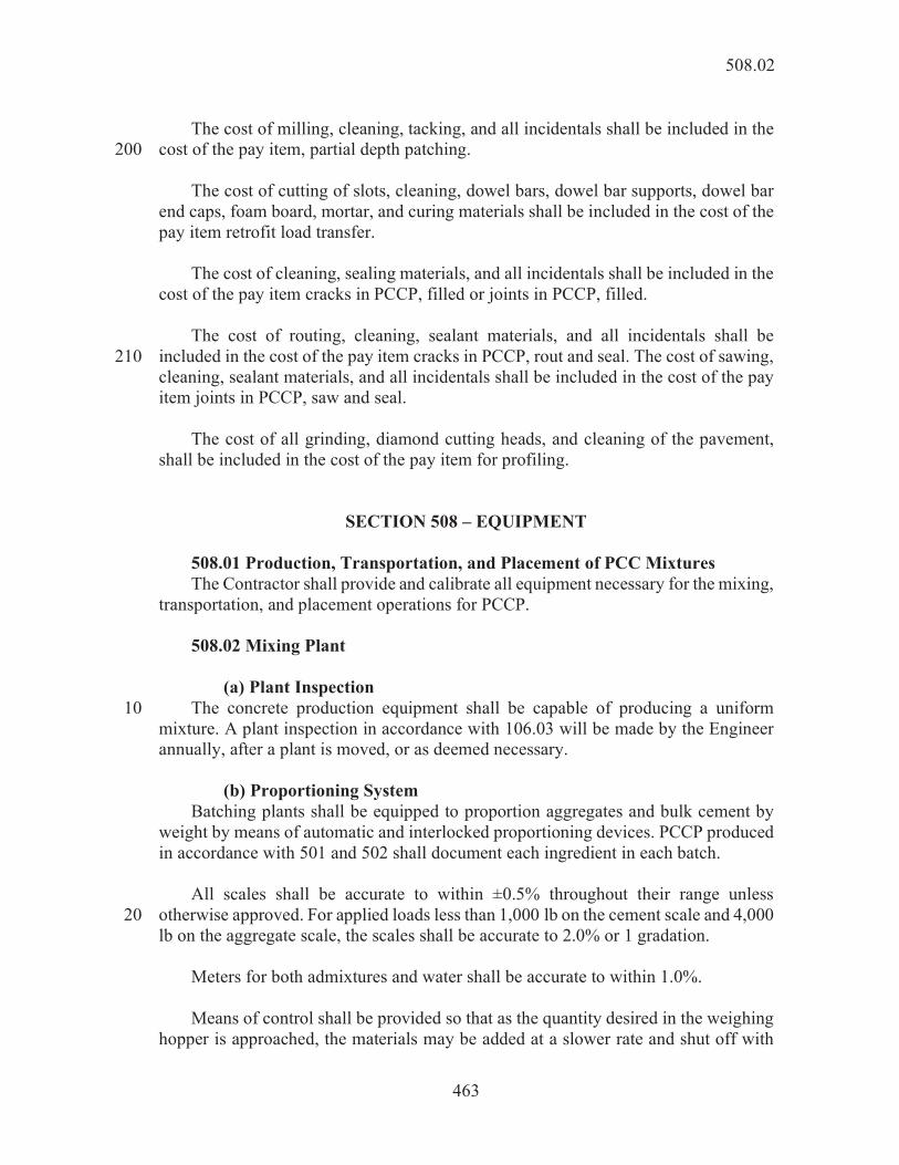
463
The cost of milling, cleaning, tacking, and all incidentals shall be included in the cost of the pay item, partial depth patching. 200 The cost of cutting of slots, cleaning, dowel bars, dowel bar supports, dowel bar end caps, foam board, mortar, and curing materials shall be included in the cost of the pay item retrofit load transfer. The cost of cleaning, sealing materials, and all incidentals shall be included in the cost of the pay item cracks in PCCP, filled or joints in PCCP, filled. The cost of routing, cleaning, sealant materials, and all incidentals shall be included in the cost of the pay item cracks in PCCP, rout and seal. The cost of sawing, 210 cleaning, sealant materials, and all incidentals shall be included in the cost of the pay item joints in PCCP, saw and seal. The cost of all grinding, diamond cutting heads, and cleaning of the pavement, shall be included in the cost of the pay item for profiling.
SECTION 508 – EQUIPMENT 508.01 Production, Transportation, and Placement of PCC Mixtures The Contractor shall provide and calibrate all equipment necessary for the mixing, transportation, and placement operations for PCCP. 508.02 Mixing Plant (a) Plant Inspection The concrete production equipment shall be capable of producing a uniform 10 mixture. A plant inspection in accordance with 106.03 will be made by the Engineer annually, after a plant is moved, or as deemed necessary. (b) Proportioning System Batching plants shall be equipped to proportion aggregates and bulk cement by weight by means of automatic and interlocked proportioning devices. PCCP produced in accordance with 501 and 502 shall document each ingredient in each batch. All scales shall be accurate to within ±0.5% throughout their range unless otherwise approved. For applied loads less than 1,000 lb on the cement scale and 4,000 20 lb on the aggregate scale, the scales shall be accurate to 2.0% or 1 gradation. Meters for both admixtures and water shall be accurate to within 1.0%. Means of control shall be provided so that as the quantity desired in the weighing hopper is approached, the materials may be added at a slower rate and shut off with
508.02

464
precision. The following proportioning tolerances shall be used for batching: 1. admixtures ....................................... ±3% 2. aggregates ........................................ ±2% 30 3. cementitious materials ..................... ±1% 4. water, volume or weight .................. ±1%. The plant shall be equipped with a recording device capable of producing a ticket to permanently record the batch number, time of day, weight of all materials in the mix, volume or weight of mixing water added, and admixture quantities or equipped with a suitable non-resettable batch counter which will indicate correctly the number of batches produced. The CMD number shall be included on the ticket. (c) Material Storage 40 The plant shall have separate storage bins or tanks for each material in the mixture. Each compartment shall discharge efficiently and freely into the weighing hopper or feed through a meter. 1. Aggregates The aggregate storage area shall be well drained. All stockpiles shall be sufficiently separated and identified by signs or other approved methods. 2. Cementitious Materials The storage bins shall be sealed and vented to preclude dusting during operation 50 and have a sampling port. 3. Admixtures Separate tanks for each admixture shall be provided. (d) Hoppers Weighing hoppers shall be constructed to eliminate accumulation of materials and to discharge fully. The fine aggregate and coarse aggregate shall be weighed separately into a weigh hopper in the respective amounts defined in the CMD. Separate scales and hoppers shall be used for weighing the cement. Pozzolans may be weighed into 60 the cement hopper in one cumulative operation provided that the portland cement is weighed in first. (e) Mixing System The concrete mixing system shall be either a central stationary mixer or a transit truck mixer. Each mixer shall have attached in a prominent place a manufacturer’s plate showing the capacity of the drum in terms of volume of mixed concrete, the speed of rotation of the mixing drum or blades, and the manufacturer’s name and address. 70 The mixer shall be capable of combining the ingredients of the concrete within the specified time into a thoroughly mixed and uniform mass.
508.02

465
1. Central or Stationary Mixers Stationary mixers shall be equipped with a timing device which does not enable the batch to be discharged until the specified mixing time has elapsed. 2. Truck Mixers Truck mixers shall be equipped with means by which the number of revolutions of the drum at mixing speed may be verified. 80 508.03 Transportation (a) Truck Mixers and Truck Agitators Truck mixers and agitators shall be capable of maintaining and discharging the concrete at a satisfactory rate and degree of uniformity. The haul units shall be examined daily for accumulations of hardened concrete or mortar and compared to the manufacturer’s standard for wear of blades. (b) Non-Agitator Trucks 90 Bodies of non-agitating hauling equipment shall be smooth, mortar tight, metal containers. They shall be capable of discharging the concrete at a controlled rate. The bodies shall be examined daily for accumulations of hardened concrete, mortar, or foreign matter. 508.04 Placement Equipment (a) Slipform The paver shall spread, consolidate, and shape the freshly placed concrete in one complete pass to provide a dense and homogeneous pavement. The paver shall be of 100 sufficient weight and power to construct the specified PCCP, at an adequate variable forward speed, and without transverse, longitudinal, or vertical instability. The paver shall be equipped with an automated steering and elevation control system. The paver shall consolidate by vibrating the concrete for the full width and depth of the PCCP. Vibration shall be accomplished by internal vibrators, which have a variable frequency range of 7,000 to 12,000 vibrations per minute. The amplitude of vibration shall be between 0.025 in. and 0.06 in. The vibrators shall be spaced and operated to achieve acceptable consolidation. The paver shall include a handheld tachometer or other suitable device for measuring the frequency of the vibrators. The 110 automated vibrator control shall be capable of stopping vibration when forward movement ceases. Mechanical tie bar inserters shall be rigidly attached to the paver and may be operated manually or automatically controlled. A mechanical belt placer, if used, shall have a re-combining deflector plate mounted on the end of the discharge belt.
508.04
466
(b) Form Riding Equipment 120 The finishing machine shall be supported by forms and be equipped with two or more oscillating type transverse screeds and a transverse smoothing float. Forms for riding equipment shall be of sufficient thickness to maintain the true cross section and shall be furnished in sections no less than 10 ft in length. Forms shall have a minimum depth equal to the prescribed edge thickness of the concrete pavement without a horizontal joint, and a minimum base width equal to the depth of the forms. Flexible or curved forms shall be of an acceptable design. Forms shall be provided with adequate devices for secure setting so that when in 130 place they can withstand, without visible spring or settlement, the impact and vibration of the consolidating and finishing equipment. Flange braces shall extend outward on the base a minimum of 2/3 of the height of the form. The top face of the form shall not vary from a true plane by more than 1/8 in. in 10 ft and the upstanding leg shall not vary by more than 1/4 in. The forms shall contain provisions for locking the ends of abutting form sections together tightly for secure setting. The transverse screed and transverse smoothing float shall be suspended from and guided by a rigid frame. The frame shall have a maximum effective wheel base of 14 ft. The length of the float shall be approximately 2 in. less than the normal width of 140 the pavement and have an adjustable crown section. The forward speed of the float shall be adjustable. The vibration equipment shall consolidate the full width and depth of the strip of PCCP being placed. Vibrators may be either the surface pan type or the internal type with either immerse tube or multiple spuds. Vibrators may be attached to the spreader or the finishing machine or mounted on a separate carriage. The frequency of the surface pan type shall be 3,500 impulses per minute or greater. The frequency of the internal type shall have no less than 5,000 150 impulses per minute for tube vibrators and spud vibrators shall have a frequency of from 10,000 to 12,000 impulses per minute in air. The paver shall include a device, such as a handheld tachometer for measuring the frequency of the vibrators. Vibrators shall have automatic controls, which stop vibration when forward motion ceases. The maximum spacing of spud vibrators shall be 2 ft. A warning device shall be connected to each vibrator circuit to indicate a failure of any individual vibrator and shall be visible from the ground. (c) Hand Placement 160 1. Steel Forms Steel forms shall be 10 ft or greater in length. Forms shall be capable of being staked in three locations or more for each 10 ft section and shall be equipped to interlock. Forms shall support finishing equipment without deflection in either the
508.04

467
vertical or horizontal direction. The top face of the form shall not vary from a true plane by more than 1/8 in. in 10 ft. 2. Wood Forms Wood forms shall support finish equipment without deflection in either vertical 170 or horizontal direction. 3. Finishing Equipment The finish device or machine shall be capable of producing a uniform surface free of voids and in accordance with the planned profiles and cross section. A mechanical tube finisher shall consist of a single or multiple rotating strike-off/finish tubes setting approximately transverse to the longitudinal movement of the machine. The length of finish tubes shall be a minimum of 2 ft longer than the planned PCCP width. The forward speed of the machine as well as the rate of the finish 180 tube rotation shall be variable and it shall be reversible to allow for multiple finish passes. A vibratory screed finisher shall consist of a truss frame with a minimum base width of 1 ft, which extends across the transverse width of the PCCP. The frame shall extend 2 ft beyond the width of the PCCP and shall hold its shape when moved forward. The screed shall move forward with either hydraulic or manual winches, which are capable of maintaining the screed at a right angle to the direction of travel. The screed shall be vibrated as it moves forward and the vibration shall stop when forward motion ceases. Vibration shall be accomplished with mechanical driven 190 eccentric weights or with auxiliary driven pneumatic vibrators. A mechanical bridge deck finishing machine shall consist of a single or multiple rotating cylinders setting approximately parallel to the longitudinal movement of the machine and operating transversely. The forward motion of the machine as well as the transverse movement of the finish cylinders shall be variable. A hand operated strike off shall be rigid and shall hold its shape when moved forward with a combined longitudinal and transverse motion. 200 A mechanical belt placer, if used, shall have a re-combining deflector plate mounted on the end of the discharge belt. 4. Vibrators Hand spud vibrators shall be capable of transmitting 7,000 to 10,800 impulses per minute in air. The diameter of the head shall be 1 1/4 to 2 1/2 in. 508.05 Curing Mechanical equipment shall be self-supported and ride on wheels or tracks located outside the paving lane. The mechanical sprayer shall be capable of applying a 210 continuous uniform film at a minimum rate of 1 gal./150 sq ft and shall be of the fully
508.05

468
atomizing type. The equipment shall provide adequate agitation of the compound during application. Hand spraying equipment shall be of the fully atomizing type. 508.06 Texturing Equipment Mechanical texturing equipment shall be capable of forming transverse grooves of uniform depth and alignment in the plastic PCCP, without tearing the surface. The texturing comb shall have steel tines spaced as specified. 220 Hand tools consisting of fluted floats, rakes with spring steel tines, or finned floats with a single row of fins shall produce grooves which conform to the same requirements as those specified for the grooves formed by the mechanical equipment. 508.07 Sawing Equipment Sawing equipment shall be self-propelled single or gang-mounted units. The saw shall be capable of maintaining the specified alignment and depth of cut without damaging the PCCP. 230 508.08 Miscellaneous Equipment (a) Hand Tools pavement shall have blades no less than 5 ft in length and 6 in. in width. Equipment made of or coated with aluminum or aluminum alloys shall not be used. Straightedges shall be 10 ft in length and mounted on a long handle. The handle shall be 3 ft longer than 1/2 of the width of the pavement being placed. 240 (b) Joint Sealing Joint sealant material shall be installed using manufacturer’s recommended equipment. Air compressors shall be capable of producing a minimum air pressure of 80 psi. Water blasting equipment shall be capable of operating at 1,500 psi without damaging the PCCP. (c) Grinding 250 Grinding shall be completed by mechanical grinding equipment using diamond tipped saw blades mounted on a power driven, self-propelled machine containing transverse and longitudinal grade controls. The cutting head shall be no less than 36 in. wide to produce a uniform texture per the full width of the cutting head shaft. The pavement surface after cutting shall have a uniform texture but shall not be smooth or polished. Tearing or dislodging of aggregates will not be allowed.
508.06

469
508.09 Testing Facility and Equipment 260 (a) Testing Facility Testing facility shall be capable of maintaining a controlled curing environment in accordance with AASHTO T 23 and contain sufficient storage tanks with curing solution to cure both production control and acceptance test beams. Water shall be conveniently available for cleaning testing equipment and for serving other tasks at the facility. Office space, having suitable heat and air conditioning, shall be provided to the Department within the testing facility. A telephone shall be provided in the testing facility. Floor space shall be provided for a Department furnished beam breaker. 270 A current set of AASHTO’s Standard Specifications for Transportation Materials and Methods of Sampling and Testing, Part 2 Tests, and ASTM C173 shall be provided. (b) Testing Equipment Testing equipment shall be provided to perform production control testing and shall be maintained in suitable working order. The equipment shall be in accordance with AASHTO requirements where applicable. The Contractor shall provide a spud vibrator with power source in suitable working order. 280 (c) Profilograph The profilograph shall be in accordance with ITM 912. (d) Straightedge – 16 ft A 16 ft straightedge shall be a rigid beam mounted on two solid wheels on axles 16 ft apart. The straightedge has a mounted push bar to facilitate propelling the device along or across the pavement. Tolerance points are located at the 1/4, 1/2, and 3/4 points and may be composed of threaded bolts capable of being adjusted to the tolerance required. 290 (e) Straightedge – 10 ft A 10 ft straightedge is the same as a 16 ft straightedge except that the wheels are mounted 10 ft apart. A handheld rigid beam may be substituted.
SECTION 509 - PORTLAND CEMENT CONCRETE PAVEMENT, PCCP, JOINT REPAIR
509.01 Description This work shall consist of partial depth repairs and bottom-half of slab repairs at PCCP joints in accordance with 105.03.
509.01
470
MATERIALS 509.02 Materials 10 Materials shall be in accordance with the following: Admixtures for Use in Concrete ......................................... 912.03 Chemical Anchor System ................................................... 901.05 Coarse Aggregate, Class A, Size No. 12* .......................... 904.03 Curing Materials ................................................................. 912.01(e)2 Epoxy Coated Reinforcing Bars ......................................... 910.01(b)9 Fine Aggregate, Size No. 23 .............................................. 904.02 Joint Filler........................................................................... 906.01 Joint Sealant, Hot Poured ................................................... 906.02(a)2 20 .................................................................. 912.04 Portland Cement ................................................................. 901.01(b) Rapid Hardening Hydraulic Cement .................................. 901.01(d) Rapid Setting Patch Materials** ........................................ 901.07 Water .................................................................................. 913.01 * Crushed stone only ** The material may be extended with a coarse aggregate
that is approved by the manufacturer and the Engineer. Organic retarders, including food grade citric acid, may be used in concrete 30 containing rapid hardening hydraulic cement. Prepackaged concrete patching material shall be identified as grade 3U18 or 3U58 and selected from the of Concrete for PCCP Joint Repair. 509.03 Concrete Mix Design A concrete mix design, CMD, for the partial depth joint repair and bottom-half joint repair shall be identified as being one of the following types and shall be in accordance with 509.04. 40 (a) Prepackaged concrete patching material, CPM (b) Ordinary portland cement-based concrete, OPCC (c) Rapid hardening cement-based concrete, RHCC (d) (e) -VE (f) Rapid setting patch materials, RSP. , -VE shall be submitted in accordance with 506.03, except that the trial batch shall be in accordance with 509.05. Prepackaged concrete patching materials, CPM and RSP, are 50 not required to follow the submittal format of a CMDS, however, the Department shall be notified of their intended use. The CMDS, or notification of using CPM or RSP, shall be submitted a minimum of seven calendar days prior to the trial batch.
509.02

471
509.04 Concrete Mix Criteria -VE shall be at least 48% but not more than 52% of the total volume of the aggregate in each unit volume of concrete. Proportions shall be based on aggregates in the bulk SSD condition. , -VE 60 shall meet the requirements stated in the table below. Aggregate volumes within the repair concrete will be determined based on the bulk SSD properties for each aggregate:
Combined Gradation of Coarse and Fine Aggregates Sieve Size Percent Passing
3/8 in. (9.5 mm) 98 - 100 No. 4 (4.75 mm) 77 - 93 No. 8 (2.36 mm) 40 - 80
No. 16 (1.18 mm) 25 - 50 No. 30 (600 μm) 15 - 35 No. 50 (300 μm) 0 - 18
No. 100 (150 μm) 0 - 8 No. 200 (75 μm) 0 - 2.3
(a) CPM or OPCC CPM or OPCC shall produce workable mixtures, with the minimum amount of water, having the following properties: Portland cement content ..................................................... 846 lb/cu yd 70 Maximum slump for OPCC and CPM 3U18 ...................... 1.5 in.A Maximum slump for CPM 3U58 ........................................ 6 in.A Maximum water/cementitious ratio .................................... 0.400B Air Content ......................................................................... 7.0% ±1.5% Minimum modulus of rupture............................................. 500 psi at 7 daysC Minimum compressive strength .................................. 3,200 psi at 7 daysD Maximum shrinkage in air ........................................... 0.060% at 28 daysD Relative Yield for OPCC .................................................... 1.00 ±0.02 A Measured five minutes after discharge from the mixer. 80 B The target water cement ratio shall be established at the time of
the trial batch and shall be based on the slump requirement. C Concrete beams and cylinders cast for the purpose of evaluating
the mix criteria shall be cured in accordance with AASHTO T 23 Section 10.1, Standard Cure conditions.
D The maximum allowable shrinkage will only apply if the
Contractor requests to omit tooling as part of re-establishing the 90
509.04

472
longitudinal joint prior to sawing. Testing shall be in accordance with ASTM C157 and conducted on specimens cast using the same materials stated in the CMDS. Approval will be based on a type A certification in accordance with 916 which shall be submitted to the Department’s Concrete Engineer.
Air entraining admixtures may be used. No other chemical admixtures shall be used. (b) RHCC, LMC, or LMC-VE 100 -VE shall be proportioned to meet the following requirements and properties: Portla .......................... 658 lb/cu yd, minimum Rapid hardening cement content -VE .................................... 658 lb/cu yd, minimum -VE ..................... 3.5 gal/94 lb cement Maximum allowable water/cementitious ratio ...................................................................... 0.400A Maximum allowable water/cementitious ratio 110 -VE ............................................................... 0.440A Maximum allowable water/cementitious ratio for RHCC.................................................................... 0.450B Slump ................................................................................. 3 to 7 in.C Air Content for RHCC........................................................ 6.5% ±1.5%D Air C -VE ................................... 0.0% - 6.0% Minimum modulus of rupture............................................. 500 psiE Minimum compressive strength ......................................... 3,200 psiE Maximum shrinkage in air ........................................... 0.060% at 28 daysF
120 A Including the water in the latex. B During production of RHCC, the water cement ratio shall be
maintained within ±0.020 of the target stated on the CMDP, not to exceed 0.450.
C Measured four to five minutes after discharge from the mixer. D If the RHCC has a permeability of 900 coulombs or less at 56
days, the acceptable range of air content is allowed to be the same 130 -VE. Verification of this property will be
determined from testing of specimens cast at the trial batch. Testing will be done per AASHTO T 277, with the value determined by averaging the result of two specimens.
E Concrete beams and cylinders cast for the purpose of evaluating
the mix criteria shall be cured in accordance with AASHTO T 23 -VE
shall achieve the minimum modulus of rupture in 12 hours or less.
509.04

473
rupture in 24 hours 140 , -VE shall provide opening to
traffic within the requirements for maintenance of traffic and lane closure restrictions.
F The maximum allowable shrinkage will only apply if the
Contractor requests to omit tooling the longitudinal joint prior to sawing. Testing shall be in accordance with ASTM C157 and conducted on specimens cast from concrete at the trial batch. Approval will be based on a type A certification in accordance with 916, which shall be submitted to the Department’s Concrete 150 Engineer.
(c) RSP Prepackaged RSP material may be extended with a coarse aggregate as recommended by the manufacturer. Water shall be added in an amount not to exceed the amount recommended by the manufacturer. The material shall meet the same requirements for slump, compressive strength, and shrinkage as stated in 509.04(b). 509.05 Quality Control Plan A quality control plan, QCP, shall be in accordance with sections 1.1 through 4.7 160 of ITM 803, except that the Quality Control Technician shall be an ACI Certified
information concerning aspects of producing, placing, finishing, and curing the joint repair concrete for joint restoration: (a) Copies of all applicable AASHTO, ASTM, and ITM standards
relevant to work being performed. (b) Testing facility, if applicable, and a list of testing equipment
meeting the requirements of Section 6.3.1 of ITM 803. 170 (c) Materials shall be identified as to their source, transportation,
handling, and storage. (d) Process control of aggregate when bulk aggregate is used. To
include, but not limited to: 1. Gradation testing for each aggregate and calculation of
blended gradation for control within allowable tolerance. 180
2. Absorption values for each aggregate, how they were
determined, and subsequently checked. 3. Daily measurement and control of moisture content of
each aggregate used in the concrete.
509.05

474
(e) Trial batch demonstration shall be described as to procedures, location, mixing equipment, batching sequence, accuracy, and verification. The identification and intended use of each 190 concrete mix.
(f) Batching of concrete during repair operations shall be described
to include weighing on scales, intended size of the batch, batching method, sequence, and mixing time. The methods to monitor materials used and the record of each batch shall also be included.
(g) Process control of concrete to address sampling and testing for
slump, relative yield, air content, water cementitious ratio, and 200 temperature. The frequency of tests shall be the first batch of the day and not less than three times per day including the first. If volumetric batching of concrete is utilized, the yield will be checked as described in 722.05(a) at the beginning of the day and not less than two times per day including the first load from each mobile mixer. The QCP shall include details as to actions in response to test results.
(h) Joint repair operations shall be described, to include the
materials and equipment used for re-establishing longitudinal 210 and transverse joints; delivery, placement, consolidation, finishing, smoothness, texturing, curing of concrete, and procedures for monitoring each operation.
(i) Process control for weather restrictions shall be addressed,
including what materials will be on-hand to protect the edges and surface of the repair area, and what corrective actions are proposed in case the joint repair concrete is damaged by rain.
(j) Documentation and submittals. 220 509.06 Trial Batch A trial batch shall be produced and tested to verify that the repair concrete is in
-VE, or RSP material. The trial batch shall be conducted prior to production. The equipment used for mixing concrete at the trial batch shall be the same as what is identified in the QCP for use during field production. The modulus of rupture from flexural strength testing and compressive strength will be determined by averaging a minimum of two tested specimens for each age. The 230 beams and cylinders shall be cured in accordance with AASHTO T 23 Section 10.1, Standard Cure conditions. Only the specimen types intended for job control in accordance with 509.14 and determining opening to traffic strength in accordance with
509.06

475
509.17 are required to be included in the trial batch. The Engineer will test the concrete for the plastic and hardened concrete properties as follows using the property values listed in 509.04. CPM OPCC RHCC,
-VE RSP
Compressive strength 12, 36, 72 h 12, 36, 72 h 12, 24, 48 h 3, 6, 12, 24 h 3, 6, 12 h
Modulus of rupture 12, 36, 72 h 12, 36, 72 h 12, 24, 48 h 3, 6, 12, 24 h 3, 6, 12 h
Plastic testing air, slump, W/C ratio*
relative yield, air, slump, W/C ratio*
relative yield,
air, slump
relative yield, air, slump slump
*The W/C ratio will be calculated after mix has been tested for slump. The Engineer will provide the Contractor the results of the tests. Relative yield will be measured in accordance with 722.05(a) for repair concrete produced in a 240 volumetric mixer. Mobile mixers will be calibrated in accordance with 722.13. The trial batch shall be of a sufficient quantity to allow the Engineer to perform all required tests from the same batch. Trial batch concrete shall not be used for more than one test.
CONSTRUCTION REQUIREMENTS 509.07 Pre-Work Meeting Requirements A pre-work meeting between the Engineer and the Contractor will be held on-site 250 prior to beginning the work. The Contractor shall be prepared to discuss the following: (a) Work schedule (b) Traffic control plan (c) Equipment calibration and adjustments (d) Inspection and evaluation of the condition and adequacy of
equipment, including units for transport of materials 260 (e) CMDP (f) The Contractor’s daily rate of production per work crew (g) QCP. 509.08 PCCP Removal PCCP removal areas for partial depth repairs will be determined by sounding and
509.08

476
will be marked. The Contractor shall remove all concrete to the limits shown on the 270 plans or as directed by the Engineer. A machine configured to safely and consistently mill the necessary profile as detailed on the plans shall be provided. The teeth on the milling head shall be spaced at either 1/2 in. or 5/8 in. The milling machine shall be subject to approval by the Engineer prior to the start of milling operations. Whenever possible, the rotating axis of the milling head shall operate perpendicular to the joint being repaired. Should PCCP removal be confined to one side of a joint, the milling machine shall be controlled so as to not cause damage to the adjacent pavement. Unless otherwise approved by the Engineer, areas that are less than 1 sq ft shall be removed by saw cutting and chipping. The saw cutting shall be to a depth of 2 in. 280 within the marked area. Overlapping saw cuts at the outer perimeter of the repair shall not extend more than 2 in. beyond the intersection. Removal of the concrete within the limits of the saw cuts shall be by hand chipping tools or handheld mechanically driven equipment. Mechanical hammers may be used to remove the concrete inside the area delineated by the saw cuts, but shall not be heavier than a nominal 35 lb class. Mechanically driven tools shall be operated at a maximum angle of 45° from the PCCP surface. A jack hammer with a wide chisel bit shall be used at a distance of 2 in. from the saw cut to remove the vertical edge and create a taper similar to the milling operations. 290 Removal areas within jointed reinforced concrete pavement, JRCP, are not required to utilize milling to initiate partial depth repairs. Saw cutting and hand chipping may be used as described above. Any wire mesh reinforcement exposed during the removal operations shall be removed. PCCP removal areas shall not remain open overnight unless otherwise approved by the Engineer. Shoulders or adjacent PCCP damaged during the removal operations shall be repaired as directed. Milling, or sawing and hand chipping, is allowed for transverse joint repairs that 300 intersect a longitudinal joint that has already undergone partial depth joint repair. Removal areas along a longitudinal joint shall not disturb a transverse joint that has already undergone partial joint repair in accordance with this specification. Prior to any transverse joint repair that intersects a previous longitudinal repair, the existing partial depth repair along the longitudinal joint shall have achieved at least 12 h of curing, a passing soundness inspection, and adequate strength, as defined in 509.17. If there is no need for the transverse joint repair to completely cross the longitudinal joint, milling operations along the transverse joint shall stop short of the longitudinal joint so as not to cause damage beyond the longitudinal joint. Sawing and hand chipping shall be used to complete the removal process up to the longitudinal joint. 310 ongitudinal joint repairs shall be terminated 12 in. or more from a transverse joint. The Engineer will check milled surfaces after PCCP removal to identify any
509.08

477
sounding with a rock hammer. Areas of unsound concrete will be marked and shall be removed with a chipping hammer. Removal of unsound concrete below the elevation of the tops of dowel bars or tie bars is not intended and unsound concrete shall remain in place in these areas. For transverse joints, any voids or significant surface 320 irregularities resulting from the hand chipping operations that extend below the elevation of the top of the dowel bars shall be filled using hand placed clean sand to make a uniform, level, bedding material to support the joint filler. For longitudinal joints, void space below the elevation of the top of tie bars shall be filled with repair concrete. Dowel bars shall not be damaged during the removal of unsound concrete. At locations where a transverse joint meets the edge of pavement, or where joints intersect, the Engineer will determine if the concrete is deteriorated for the entire depth, within the limits detailed on the plans for bottom-half joint repair. If either end 330 of a dowel bar is exposed or misaligned in a bottom-half joint repair, the exposed portion shall be removed or cut flush with the concrete surface, as directed by the Engineer. If the combination of removal for partial depth joint repair and bottom-half joint repair exposes more than two adjacent dowels at a contraction joint, the Engineer shall be notified to determine if full depth patching is to be conducted in accordance with 506.08(b). If a snowplowable raised pavement marker is to be installed in an area of partial 340 depth joint repair, the width of the removal area, in proximity to where the RPM is to be installed, may be increased in order to provide the necessary clearances as specified in 509.16. 509.09 Surface Preparation and Joint Filler Installation The milled or hand chipped cavities shall be prepared to provide a clean, irregular surface for the development of a good bond between the joint repair concrete and the existing pavement. Broken concrete pieces shall be removed and the cavities shall be swept clean. 350 The surface of the cavity shall be thoroughly sandblasted and cleaned with compressed air to remove all dust and chips. Cleaning with compressed air shall be performed as close to placing the concrete as possible, but not after installing any joint filler. If joint filler material has been installed, the surface may be cleaned again by using compressed air at low pressure so as to not damage the in-place filler or sand below the top of any exposed dowel bar just prior to placing the grout or concrete. The air lines for sandblasting and compressed air cleaning shall be equipped with oil traps to prevent contamination of the surfaces. (a) Joint Filler - General Requirements 360 The installation of joint filler is required before concrete placement and shall be
509.09

478
of a width that matches the existing transverse or longitudinal joint being repaired or a minimum width of 3/8 in, whichever is greater. The joint filler shall extend at least 3 in. beyond the length of the patch area. Joint filler shall be installed as one piece for the depth of the repair. Splicing long lengths of joint filler may be allowed. The method of splicing shall be subject to approval by the Engineer. (b) Joint Filler at Transverse Joints and Bottom Half Repairs Use of joint filler is required for establishing compression relief at all existing transverse D-1 contraction joints and along both the longitudinal and transverse joint 370 sides of a bottom-half repair. The joint filler shall not only re-establish the joint within the repair but shall also prevent the infiltration of the concrete into and across the crack or joint. Prior to placement of the joint filler at a transverse contraction joint, the joint shall be tooled or widened sufficiently at the bottom of the repair to create a slot so that the joint filler can be inserted a minimum of 1/4 in. below the bottom of the repair concrete. The base of the slot shall not extend below the elevation of the top of any exposed dowel bar. Joint filler shall be cut or trimmed to match the irregularities of the concrete at the bottom of the slot. Duct tape shall be placed as a bond breaker on exposed dowel bars. 380 Any void space that exists below the top of exposed dowels shall be filled with clean No. 23 natural sand that is sufficiently dry to flow into the gap. (c) Longitudinal Joints Joint repairs at longitudinal joints shall utilize either a joint filler to re-establish the joint or perform both of the following: 1. Tool the plastic repair concrete after placement to create a
weak plane at the original joint location. The joint tooling 390 equipment shall be identified in the QCP and approved by the Engineer prior to use. Tooling of the joint may be eliminated if the concrete used in the patch has been verified by the Engineer as meeting the shrinkage requirements stated in 509.04.
2. Saw the joint after the repair concrete has adequately
hardened. Sawing of the tooled joint shall be performed with a 1/4 in. blade. Sawing shall be done with care as soon as possible without causing excessive raveling of the repair 400 material. The depth of the saw cut shall extend below the full depth of the repair by at least 1/4 in., but no closer than 1 in. above the tie bar. If it is determined that a crack forms at the bottom of the tooled joint before sawing can be performed without raveling, sawing to re-establish the joint shall not be performed.
509.09

479
Areas designated by the Engineer as requiring bottom-half joint repair shall be prepared as shown on the plans. The reinforcing bars shall be installed in accordance with 503.03(g). 410 509.10 Concrete Mixing and Transportation For onsite weighing and batching of OPCC or RHCC, the appropriate number of pre-packaged bags of cement, shall be at the mixing site to accommodate the day’s production. The fine and coarse aggregate shall be pre-weighed to within 2% of their target for the batch size and placed in appropriate containers. Each aggregate component for a batch shall be identified as to material and weight, to facilitate accurate batching into the mixer in the proper sequence. Water, air entraining agent, and chemical admixtures, if appropriate, shall be at 420 the mixing site. The water necessary to provide the required slump shall be measured by weight or volume and recorded for each batch. All components of cement, aggregates, water, air entraining agent, and any organic retarder shall be charged into a paddle type mixer according to the sequence defined in the QCP and mixed for a minimum of five minutes. The location of mixing shall be on the job site in close proximity to the joint repair operations. Prepackaged concrete, CPM 3U18, and an air entraining admixture, may be used instead of batching individual components. Pre-packaged concrete, CPM 3U58, shall not be modified with admixtures. 430 A prepackaged RSP material containing coarse aggregate may be used. Addition of water and mixing shall be in accordance with the manufacturer’s instructions. Wash water shall not be used as a portion of the mixing water for any joint repair concrete. -VE shall be mixed in a mobile type volumetric mixer meeting the requirements of 722.09(a). The Engineer may also allow batching and mixing of OPCC or RHCC in a mobile-type volumetric mixer except the mixer shall carry 440 sufficient quantities of unmixed ingredients to produce at least 2 cu yds and is not required to be self-propelled. Calibration of the mixer shall be in accordance with 722.13. 509.11 Weather Limitations Joint repair concrete that has been placed shall be protected from rain. Materials described in the QCP for protection of the edges and surface of the repair area shall be readily available for use. Should any damage result, the Engineer will suspend operations until corrective action as described in the QCP is taken. 450 Joint repair concrete shall not be placed when either the ambient temperature or existing concrete pavement temperature is less than 50°F.
509.11

480
Temperature restrictions for chemical anchor systems used in anchoring deformed steel reinforcement for bottom half repairs shall be in accordance with the manufacturer’s recommendations. 509.12 Placing and Finishing Concrete CPM, OPCC, and RSP repair concrete shall be placed within 15 minutes of
-VE shall be placed within five minutes of mixing. 460 All repair concrete shall be placed such that a cold joint does not occur within the limits of an individual, or intersecting, longitudinal or transverse joint repair. Placement may be isolated to one side of a joint if the joint face or joint filler is properly supported. Repair along a transverse joint that intersects a previously repaired longitudinal joint is allowed as described in 509.08. For CPM and OPCC material, the cleaned surface shall be lightly sprayed with water to wet the surface without ponding and a bonding grout shall be applied to the prepared surface. The grout shall consist of two parts Type I or Type II portland cement and one part sand mixed with sufficient water to form a slurry that can be 470 spread evenly onto the prepared concrete surface. The grout shall be mixed mechanically and applied by brushing or scrubbing, with a stiff bristle broom, onto the prepared and wetted concrete surface. The pot life of the grout shall not extend beyond 1 h. CPM or OPCC repair material shall be placed immediately after applying the bonding grout. -VE, thoroughly soak the cleaned surface and maintain it in a wet condition for at least 2 h immediately prior to placing the repair concrete. Maintaining a wet surface shall be accomplished by covering the soaked surface with wet burlap. The burlap shall be re-wetted as necessary. A layer of white 480 opaque polyethylene film, that is at least 4 mils thick, may be used to offset the need to rewet the burlap. Prior to placing the joint repair material, the burlap shall be removed. Any standing water in depressions, holes, or areas of concrete removal shall be blown out with compressed air or other type of blower sufficient for removal, or by the use of an approved vacuum system. The surface shall be damp at time of placing the repair concrete. Bonding grout shall not be used. For RSP material, the cleaned surface shall be lightly sprayed with water to thoroughly wet the surface without ponding. RSP repair material shall be placed immediately after wetting the surface. Bonding grout shall not be used. 490 When using a bonding grout, if the material dries or whitens prior to placing the concrete joint repair material, the repair material shall not be placed. The dried grout shall be thoroughly removed by sandblasting and cleaning as specified in 509.09. Concrete for partial depth joint repair shall be placed monolithically with concrete for bottom-half joint repair, using the same concrete mixture. Concrete shall be consolidated by internal vibration and struck off level to the adjacent PCCP. Joint filler shall remain straight for the length of the repair, within a tolerance of ±1/4 in. Concrete
509.12

481
shall be hand finished and shall be controlled so that excess mortar and water is not 500 worked into the surface. Final hand finishing shall have the trowels or floats work the surface from the joint toward the edge of the patch to avoid tearing the new concrete away from the existing pavement. Edging is required for fresh concrete adjacent to all joint filler or forms. Concrete repairs at transverse joints shall not protrude into an HMA shoulder by more than 3/8 in. by forming or sawing the edges. The concrete surface of the partial depth joint repair shall be textured by brooming in the longitudinal direction of the repair. All repairs shall be broom textured regardless of subsequent surface treatments. 510 The final finished surface of the repair shall not vary more than 1/8 in. from the existing pavement surface as measured with a straight edge over the joint. Partial depth patches that are not smooth shall be corrected by diamond grinding. Such grinding shall be completed after the concrete has gained sufficient strength for opening to traffic. Immediately upon completion of finishing and texturing of the partial depth joint
-VE, and RSP, grout shall be applied with a brush to the entire perimeter of the repair. Proportioning and mixing of the grout shall be the same as previously described in this section for 520 bonding of CPM and OPCC material. 509.13 Curing A resin-based liquid membrane forming compound in accordance with 912.01(e)2 shall be applied as soon as possible after the bleed water has dissipated. The compound shall be agitated in the shipping container to obtain a homogenous mixture for transfer to the job site application equipment. Application of curing compound shall be in accordance with the following: (a) Rate of application shall be at least one gallon per 200 sq ft of 530
surface curing area. (b) Curing compound shall be applied to provide a uniform, solid,
white opaque coverage on all exposed concrete surfaces similar to a white sheet of paper.
(c) If the applied curing compound is damaged by rain or other
means during the curing period, the damaged area shall be repaired as soon as possible by re-application at a rate equal to the original coat. 540
(d) If the Engineer determines that the initial, or corrective re-
application, results in unsatisfactory curing, the Engineer may prohibit the use of curing compound and instead require the use of wet double burlap or waterproof covers in accordance with 504.04.
509.13

482
Whenever weather conditions exist that cause unusual or adverse placing and finishing conditions or equipment failures occur, the application of curing materials shall be expedited, or the mixing and placing operations shall be temporarily 550 suspended as the conditions require. When a deficiency is identified in the curing process, the joint repair shall be removed and replaced. If the repair is removed exposing an underlying bottom-half repair, the bottom-half repair shall also be removed and replaced. 509.14 Job Control Control of concrete for slump, air content, or relative yield, as appropriate for the mix, and strength based on modulus of rupture obtained from flexural strength beams or compressive cylinders will be determined on the basis of tests performed by the 560 Engineer in accordance with 505. The labor necessary for concrete sampling shall be furnished as required by the Engineer. Testing for slump, air content, and relative yield as appropriate for the mix, will be on the first batch of the day and a minimum of once per every 400 cu ft thereafter. Beams or cylinders will be made for evaluating the quality of the delivered mix at least once for every three days of production or whenever slump, relative yield, or air content are failing the upper limit. The beams or cylinders will be tested for compliance with strength requirements, at an age consistent with the mixtures intended use as defined in 509.04. Beams or cylinders for this purpose shall be cured in 570 accordance with Section 10.1 of AASHTO T 23 and 505.01(a). The Engineer will notify the Contractor when measurements for slump, unit weight, air content, or modulus of rupture are outside of the specified requirements. Rounding will be in accordance with 109.01(a). 509.15 Joint Sealing Joint openings within a repair area shall be maintained for the full depth of the
transverse joints shall be sawed to create a reservoir for the sealant, to be followed by 580 cleaning and sealing. If the longitudinal joint was re-established by sawing in accordance with 509.09(c)2, additional sawing to create a reservoir for the sealant is not required. If the longitudinal joint was not sawed due to cracking in accordance with 509.09(c)2, the reservoir for the sealant shall be sawcut to a maximum depth of 7/8 in. The cleaning and sealing of the joint shall be in accordance with 507.04(a) and as follows. Transverse and longitudinal joints shall be sealed with hot poured joint sealant in accordance with the sealant manufacturer’s recommendations. Joints shall be sealed with joint sealing materials within 1/4 in. below the surface and shall extend beyond 590 the limits of the patch to any existing sealant that is to remain in place. A distributor in accordance with 409.03 shall be used with an indirect-heat, double boiler kettle and
509.14

483
mechanical agitator. The hot poured joint sealant shall be placed utilizing a “V” shaped wand tip to allow the penetration of the material into the joints. Any grinding to correct smoothness of partial depth patches shall be completed prior to joint sealing. 509.16 Snowplowable Raised Pavement Markers Snowplowable raised pavement markers, RPM, shall be located and installed in 600 accordance with 808.11, except that the marker shall be installed a minimum of 2 in. from the longitudinal joint. If the marker is installed within the limits of the partial depth patch, the slot shall be at least 2 in. from the edge of the repair. The repair material shall have attained a modulus of rupture of 500 psi or greater from flexural strength testing or 4,000 psi from compressive testing, prior to creating the slot for the adhesive and RPM. The slot may be created by grinding or by saw cutting and hand chipping. Each RPM installation will be inspected for proper installation. There shall be no visual cracks at the surface of the partial depth patch and the installation will be sounded to detect any loss of bond between the partial depth patch material and the substrate PCCP. Any such defect shall require repair of the partial depth patch and 610 reinstallation of the RPM to the satisfaction of the Engineer, which may involve removal and replacement of the partial depth patch along the longitudinal joint between the limits of the transverse contraction joints. Any such repairs shall be made at no additional cost to the Department. 509.17 Opening to Traffic Opening to traffic strength will be based on the modulus of rupture from one flexural strength test or the average of two cylinders. Cylinders will be either 6 in. by 12 in. or 4 in. by 8 in. Completed partial depth repairs and bottom-half repairs may be opened to traffic when flexural strength tests indicate a minimum modulus of rupture 620 of 500 psi or when compressive strength tests indicate a minimum of 3,200 psi based on the average of the two individual cylinder breaks. Beams or cylinders for this purpose will be cast from repair concrete placed near the very end of each day’s production for each different CMDP used and cured in accordance with Section 10.2 of AASHTO T 23 and 505.01(a). Prior to opening to traffic, the Contractor and the Engineer will conduct an inspection of the partial depth patches to determine if there are any failures. Failures will include, but are not limited to, debonding of the repair concrete or random surface cracks. Repair of the failed partial depth joint repair or bottom-half joint repair shall 630 be completed by an approved method prior to opening the pavement to non-construction traffic. 509.18 Method of Measurement Partial depth joint repair will be measured at the surface, by the square foot, using linear dimensions measured to the nearest 0.1 ft. Bottom-half joint repair will be measured by the square foot using linear
509.18

484
dimensions measured to the nearest 0.1 ft at the mid-depth of the pavement, when the following conditions are met: 640 (a) The PCCP is removed full depth to visibly expose the
subbase below. (b) The minimum number of reinforcing bars are furnished and
installed as shown on the plans. If the above requirements for bottom-half repairs are not met, the Engineer will only take measurements for payment under partial depth joint repair regardless of depth of the repair. 650 Additional removal width to accommodate the Contractor’s equipment will not be measured. For repairs at intersecting joints, the same area of joint repair will not be measured twice. Sawing and sealing of joints in areas of partial depth joint repair will not be measured. 660 509.19 Basis of Payment Partial depth joint repair and bottom-half joint repair will be paid for at the contract unit price per square foot. Measured areas of partial depth joint repair that are not located at a joint or crack will be paid as partial depth joint repair. Payment will be made under: Pay Item Pay Unit Symbol Joint Repair, Partial Depth ........................................................ SFT 670 Joint Repair, Bottom-half ......................................................... SFT The cost of the trial batch for each concrete mixture, removing and disposing of the in-place concrete pavement as marked by the Engineer, tapering the edges of the repair back at 30 to 60 degrees, cleaning, sandblasting and air blasting, treatment of dowel bars, furnishing and installing bonding grout, furnishing and installing joint filler or tooling and sawing to re-establish the joint within or along the repair, furnishing and placing the concrete within the repair, vibrating, screeding, finishing, texturing, placing cement slurry around the edges, curing and protecting the concrete, sawing and sealing to re-establishing joints, cleanup, and any other materials, labor, 680 equipment, or incidentals necessary to complete the work as specified shall be included in the cost of the joint repair, partial depth pay item. The cost of removal and disposal of the in-place concrete pavement as determined by the Engineer, cleaning sandblasting and air blasting, treatment of dowel bars,
509.19

485
furnishing and installing steel reinforcement, furnishing and installing bonding grout, furnishing and installing joint filler and sawing to re-establish the joint within or along the repair, furnishing, placing, and vibrating the concrete within the repair, sawing and sealing to re-establishing joints, cleanup, and any other materials, labor, equipment, or incidentals necessary to complete the work as specified shall be included in the cost 690 of the joint repair, bottom-half pay item. Areas of removal for PCCP Joint Repair, which after inspection by the Engineer, are determined to need PCCP Patching, Full Depth in accordance with 506.08(b), will be paid at 40% of the contract unit price per sq ft for the work represented for both Joint Repair, Partial Depth and Joint Repair, Bottom-half. PCCP Patching, Full Depth will be paid at 100% of the contract unit price. During periods of overnight lane closure, if the Engineer inspects an area of joint repair and determines that PCCP Patching, Full Depth in accordance with 506.08(b) 700 is necessary, the joint repair may be completed if needed to meet the opening to traffic requirement. If completed in order to meet the opening to traffic requirement, the joint repair will be paid at 100% of the contract unit price. Joint repair areas that do not meet the curing requirements of 509.13 shall be removed and replaced at no additional cost to the Department. Additional removal width to accommodate the Contractor’s equipment shall be at no additional cost to the Department. 710 Removal and replacement of partial depth patches and snowplowable raised pavement markers as described in 509.16 for debonding and other defects shall be at no additional cost to the Department.
509.19

486