Division 3, Subdivision W - State of Oregon: Oregon OSHAosha.oregon.gov/OSHARules/div3/div3W.pdf ·...
42
OREGON OCCUPATIONAL SAFETY AND HEALTH STANDARDS Oregon Administrative Rules, Chapter 437 DIVISION 3 (29 CFR 1926) CONSTRUCTION CONSTRUCTION Subdivision W Rollover Protective Structures: Overhead Protection Oregon Occupational Safety and Health Division (Oregon OSHA) Department of Consumer and Business Services Salem, Oregon 97301-3882 AO 5-2006
Transcript of Division 3, Subdivision W - State of Oregon: Oregon OSHAosha.oregon.gov/OSHARules/div3/div3W.pdf ·...

OREGON OCCUPATIONAL SAFETY AND HEALTH STANDARDS
Oregon Administrative Rules, Chapter 437
DIVISION 3 (29 CFR 1926) CONSTRUCTION
CONSTRUCTION
Subdivision W Rollover Protective Structures:
Overhead Protection
Oregon Occupational Safety and Health Division (Oregon OSHA) Department of Consumer and Business Services
Salem, Oregon 97301-3882
AO 5-2006

The Oregon Department of Consumer and Business Services adopted these rules pursuant to ORS 654.025(2). The Secretary of State Designated OAR Chapter 437 as the “Oregon Occupational Safety and Health Code.” Six general subject areas within this code are designated as “Divisions.” Division 1 General Administrative Rules
Division 2 General Occupational Safety and Health Rules
Division 3 Construction
Division 4 Agriculture
Division 5 Maritime Activities
Division 7 Forest Activities
Oregon Revised Statutes (ORS) 654 The Oregon Safe Employment Act (OSEAct)
Oregon-initiated rules in this division of the Oregon Occupational Safety and Health Code are numbered in a uniform system developed by the Secretary of State. This system does not number the rules in sequence (001, 002, 003, etc.). Omitted numbers may be assigned to new rules at the time of their adoption. Oregon-initiated rules are arranged in the following Basic Codification Structure adopted by the Secretary of State for Oregon Administrative Rules (OAR):
Chapter Division Rule Section Subsection Paragraphs 437 003 1760 (1) (a) (A)(i)(I)
The majority of Oregon OSHA codes are adopted by reference from the Code of Federal Regulations (CFR), and are arranged in the following basic federal numbering system:
Chapter Division Part Subpart Section Paragraphs (Subdivision)
437 003 1926 M .502 (a) The terms “subdivision” and “subpart” are synonymous within OAR 437, Oregon Occupational Safety and Health Code. To obtain an order form or copies of these codes, address:
Department of Consumer & Business Services Oregon Occupational Safety & Health Division (Oregon OSHA)
350 Winter St. NE, Room 430 Salem, OR 97301-3882
Or call the Oregon OSHA Resource Library at 503-378-3272 The rules referenced in this division are available for viewing in the Office of the Secretary of State, Administrative Rules and Office Document Section, Oregon State Archives Building, Salem, Oregon 97310, or the Central Office, Oregon Occupational Safety and Health Division of the Department of Consumer and Business Services, Room 430, 350 Winter St. NE Salem, OR 97301-3882. Please visit our web site at: www.orosha.org

Oregon Administrative Rules Oregon Occupational Safety and Health Division
ROLLOVER PROTECTIVE STRUCTURES (ROPS) FOR
MATERIAL HANDLING EQUIPMENT W
Subdivision W W-i Table of Contents
TABLE OF CONTENTS 1926.1000 Rollover protective structures (ROPS) for material handling equipment......... W-1
1926.1001 Minimum performance criteria for rollover protective structures for designated scrapers, loaders, dozers, graders, and crawler tractors .......................... W-3
1926.1002 Protective frame (roll-over protective structures, known as ROPS) for wheel-type agricultural and industrial tractors used in construction .................. W-13
1926.1003 Overhead protection for operators of agricultural and industrial tractors ...... W-21
Appendix A to Subpart W ............................................................................................ W-25

W Oregon Administrative Rules Oregon Occupational Safety
and Health Division
W-ii

Oregon Administrative Rules Oregon Occupational Safety and Health Division
ROLLOVER PROTECTIVE STRUCTURES (ROPS) FOR
MATERIAL HANDLING EQUIPMENT W
437-003-0001 W-iii (23)(a) – (23)(d)
OAR 437, DIVISION 3
CONSTRUCTION
SUBDIVISION W – ROLLOVER PROTECTIVE STRUCTURES: OVERHEAD PROTECTION
437-003-0001 Adoption by Reference. In addition to, and not in lieu of, any other safety and health codes contained in OAR Chapter 437, the Department adopts by reference the following federal regulations printed as part of the Code of Federal Regulations, in the Federal Register: (23) Subdivision W – Rollover Protective Structures: Overhead Protection. (a) 29 CFR 1926.1000 Rollover protective structures (ROPS) for material handling equipment, published 4/6/79, FR vol. 44, p. 20940. (b) 29 CFR 1926.1001 Minimum performance criteria for rollover protective structure for designated scrapers, loaders, dozers, graders, and crawler tractors, published 4/6/79, FR vol. 44, p. 20940. (c) 29 CFR 1926.1002 Protective frame (ROPS) test procedures and performance requirements for wheel-type agricultural and industrial tractors used in construction, published 7/20/06, FR vol. 71, no. 139, p. 41127. (d) 29 CFR 1926.1003 Overhead protection for operators of agricultural and industrial tractors, published 2/28/06, FR vol. 71, no. 39, p. 9909. These standards are available at the Oregon Occupational Safety and Health Division, Oregon Department of Consumer and Business Services, and the United States Government Printing Office. Stat. Auth.: ORS 654.025(2) and 656.726(4). Stats. Implemented: ORS 654.001 through 654.295. Hist: APD Admin. Order 5-1989, f. 3/31/89, ef. 5/1/89 (temp).
APD Admin. Order 8-1989, f. 7/7/89, ef. 7/7/89 (perm). APD Admin. Order 14-1989, f. 7/20/89, ef. 8/1/89 (temp). APD Admin. Order 15-1989, f. 9/13/89, ef. 9/13/89 (perm). APD Admin. Order 16-1989 (temp), f. 9/13/89, ef. 9/13/89. OR-OSHA Admin. Order 2-1989, f. 10/17/89, ef. 10/17/89. OR-OSHA Admin. Order 3-1990, f. 1/19/90, ef. 1/19/90 (temp). OR-OSHA Admin. Order 7-1990, f. 3/2/90, ef. 3/2/90 (perm). OR-OSHA Admin. Order 8-1990, f. 3/30/90, ef. 3/30/90. OR-OSHA Admin. Order 13-1990, f. 6/28/90, ef. 8/1/90 (temp). OR-OSHA Admin. Order 19-1990, f. 8/31/90, ef. 8/31/90 (perm). OR-OSHA Admin. Order 27-1990, f. 12/12/90, ef. 2/1/91. OR-OSHA Admin. Order 6-1991, f. 3/18/91, ef. 4/15/91. OR-OSHA Admin. Order 7-1991, f. 4/25/91, ef. 4/25/91. OR-OSHA Admin. Order 15-1991, f. 12/13/91, ef. 12/13/91. OR-OSHA Admin. Order 16-1991, f. 12/16/91, ef. 1/1/92. OR-OSHA Admin. Order 6-1992, f. 5/18/92, ef. 5/18/92. OR-OSHA Admin. Order 11-1992, f. 10/9/92, ef. 10/9/92. OR-OSHA Admin. Order 1-1993, f. 1/22/93, ef. 1/22/93. OR-OSHA Admin. Order 16-1993, f. 11/1/93, ef. 11/1/93 (Lead). OR-OSHA Admin. Order 1-1994, f. 4/27/94, ef. 4/27/94. OR-OSHA Admin. Order 4-1994, f. 8/4/94, ef. 8/4/94 (HazCom). OR-OSHA Admin. Order 6-1994, f. 9/30/94, ef. 9/30/94. OR-OSHA Admin. Order 1-1995, f. 1/19/95, ef. 1/19/95 (DOT markings, placards & labels). OR-OSHA Admin. Order 3-1995, f. 2/22/95, ef. 2/22/95 (Haz Waste). OR-OSHA Admin. Order 4-1995, f. 3/29/95, ef. 3/29/95 (Asbestos). OR-OSHA Admin. Order 5-1995, f. 4/6/95, ef. 4/6/95 (HazCom). OR-OSHA Admin. Order 6-1995, f. 4/18/95, ef. 6/1/95 (Fall Protection). OR-OSHA Admin. Order 8-1995, f. 8/25/95, ef. 8/25/95 (Asbestos). OR-OSHA Admin. Order 5-1996, f. 11/29/96, ef. 11/29/96. OR-OSHA Admin. Order 6-1996, f. 11/29/96, ef. 11/29/96.

W ROLLOVER PROTECTIVE
STRUCTURES (ROPS) FOR MATERIAL HANDLING EQUIPMENT
Oregon Administrative Rules Oregon Occupational Safety
and Health Division
W-iv 437-003-0001
OR-OSHA Admin. Order 2-1997, f. 3/12/97, ef. 3/12/97. OR-OSHA Admin. Order 4-1997, f. 4/2/97, ef. 4/2/97. OR-OSHA Admin. Order 6-1997, f. 5/2/97, ef. 5/2/97. OR-OSHA Admin. Order 7-1997, f. 9/15/97, ef. 9/15/97 (Fall Protection). OR-OSHA Admin. Order 8-1997, f. 11/14/97, e. 11/14/97 (Methylene Chloride). OR-OSHA Admin. Order 1-1998, f. 2/13/98, e. 2/13/98 (Methylene Chloride). OR-OSHA Admin. Order 3-1998, f. 7/7/98, ef. 7/7/98 (Respiratory Protection). OR-OSHA Admin. Order 6-1998, f. 10/15/98, ef. 10/15/98 (Slings 3/H). OR-OSHA Admin. Order 7-1998, f. 12/28/98, ef. 12/28/98 (Asbestos). OR-OSHA Admin. Order 1-1999, f. 3/22/99, e. 3/22/99 (Methylene Chloride). OR-OSHA Admin. Order 4-1999, f. 4/30/99, ef. 4/30/99. OR-OSHA Admin. Order 6-1999, f. 5/26/99, ef. 5/26/99. OR-OSHA Admin. Order 3-2000, f. 2/8/00, ef. 2/8/00. OR-OSHA Admin. Order 3-2001, f. 2/5/01, ef. 2/5/01 (Fall Protection/Oregon Exceptions). OR-OSHA Admin. Order 3-2002, f. 4/15/02, ef. 4/18/02 (Steel Erection). OR-OSHA Admin. Order 5-2002, f. 6/28/02, ef. 10/1/03 (GFCI 3/K). OR-OSHA Admin. Order 6-2002, f. 7/19/02, ef. 7/19/02 (Fall Protection/Steel Erection). OR-OSHA Admin. Order 1-2003, f. 1/30/03, ef. 4/30/03 (3/Q Masonry Wall Bracing). OR-OSHA Admin. Order 2-2003, f. 1/30/03, ef. 1/30/03 (3/G). OR-OSHA Admin. Order 7-2003, f. 12/5/03, ef. 12/5/03 (3/O). OR-OSHA Admin. Order 8-2003, f. 12/30/03, ef. 1/1/04 (3/R). OR-OSHA Admin. Order 1-2005, f. 4/12/05, ef. 4/12/05 (3/D and 3/Z). OR-OSHA Admin. Order 2-2006, f. 4/28/06, ef. 4/28/06 (3/R). OR-OSHA Admin. Order 4-2006, f. 7/24/06, ef. 7/24/06. OR-OSHA Admin. Order 5-2006, f. 8/7/06, ef. 1/1/07. OR-OSHA Admin. Order 6-2006, f. 8/30/06, ef. 8/30/06. OR-OSHA Admin. Order 10-2006, f. 11/30/06, ef. 11/30/06. OR-OSHA Admin. Order 6-2007, f. 9/26/07, ef. 9/26/07 (3/O). OR-OSHA Admin. Order 5-2008, f. 5/1/08, ef. 5/15/08 (PPE). OR-OSHA Admin. Order 5-2009, f. 5/29/09, ef. 5/29/09. OR-OSHA Admin. Order 3-2010, f. 6/10/10, ef. 6/15/10. OR-OSHA Admin. Order 1-2011, f. 2/9/11, ef. 2/9/11. OR-OSHA Admin. Order 4-2011, f. 12/8/11, ef. 12/8/11. OR-OSHA Admin. Order 5-2011, f. 12/8/11, ef. 7/1/12. OR-OSHA Admin. Order 1-2012, f. 4/10/12, ef. 4/10/12. OR-OSHA Admin. Order 5-2012, f. 9/25/12, ef. 9/25/12. OR-OSHA Admin. Order 1-2013, f. 2/14/13, ef. 2/14/13. OR-OSHA Admin. Order 2-2013, f. 2/15/13, ef. 4/1/13. OR-OSHA Admin. Order 4-2013, f. 7/19/13, ef. 7/19/13. OR-OSHA Admin. Order 5-2013, f. 9/13/13, ef. 9/13/13. OR-OSHA Admin. Order 6-2013, f. 10/9/13, ef. 10/9/13. OR-OSHA Admin. Order 7-2013, f. 12/12/13, ef. 12/12/13. OR-OSHA Admin. Order 6-2014, f. 10/28/14, ef. 5/1/15. OR-OSHA Admin. Order 7-2014, f. 11/7/14, ef. 11/9/14.

Oregon Administrative Rules Oregon Occupational Safety and Health Division
ROLLOVER PROTECTIVE STRUCTURES (ROPS) FOR
MATERIAL HANDLING EQUIPMENT W
1926.1000 W-1 (a)(1) – (c)(1)(iii)
SUBDIVISION W
ROLLOVER PROTECTIVE STRUCTURES; OVERHEAD PROTECTION
Authority: Section 3704 of the Contract Work Hours and Safety Standards Act (40 U.S.C. 3701); Sections 4, 6, and 8 of the Occupational Safety and Health Act of 1970 (29 U.S.C. 653, 655, 657); and Secretary of Labor’s Order No. 12-71 (36 FR 8754), 8-76 (41 FR 25059), 9-83 (48 FR 35736), 1-90 (55 FR 9033), 6-96 (62 FR 111), 3-2000 (65 FR 50017), or 5-2002 (67 FR 65008), as applicable.
§1926.1000 Rollover Protective Structures (ROPS) For Material Handling Equipment. (a) Coverage.
(1) This section applies to the following types of material handling equipment: To all rubber-tired, self-propelled scrapers, rubber-tired front-end loaders, rubber-tired dozers, wheel-type agricultural and industrial tractors, crawler tractors, crawler-type loaders, and motor graders, with or without attachments, that are used in construction work. This requirement does not apply to side-boom pipelaying tractors.
(2) The promulgation of specific standards for rollover protective structures for compactors and rubber-tired skid-steer equipment is reserved pending consideration of standards currently being developed.
(b) Equipment manufactured on or after September 1, 1972. Material handling machinery described in paragraph (a) of this section and manufactured on or after September 1, 1972, shall be equipped with rollover protective structures which meet the minimum performance standards prescribed in §§1926.1001 and 1926.1002, as applicable.
(c) Equipment manufactured before September 1, 1972.
(1) All material handling equipment described in paragraph (a) of this section and manufactured or placed in service (owned or operated by the employer) prior to September 1, 1972, shall be fitted with rollover protective structures no later than the dates listed below:
(i) Machines manufactured on or after January 1, 1972, shall be fitted no later than April 1, 1973.
(ii) Machines manufactured between July 1, 1971, and December 31, 1971, shall be fitted no later than July 1, 1973.
(iii) Machines manufactured between July 1, 1970, and June 30, 1971, shall be fitted no later than January 1, 1974.

W ROLLOVER PROTECTIVE
STRUCTURES (ROPS) FOR MATERIAL HANDLING EQUIPMENT
Oregon Administrative Rules Oregon Occupational Safety
and Health Division
(c)(1)(iv) - (f)(3) W-2 1926.1000
(iv) Machines manufactured between July 1, 1969, and June 30, 1970, shall be fitted no later than July 1, 1974.
(v) Machines manufactured before July 1, 1969: Reserved pending further study, development, and review.
(2) Rollover protective structures and supporting attachment shall meet the minimum performance criteria detailed in §§1926.1001 and 1926.1002, as applicable or shall be designed, fabricated, and installed in a manner which will support, based on the ultimate strength of the metal, at least two times the weight of the prime mover applied at the point of impact.
(i) The design objective shall be to minimize the likelihood of a complete overturn and thereby minimize the possibility of the operator being crushed as a result of a rollover or upset.
(ii) The design shall provide a vertical clearance of at least 52 inches from the work deck to the ROPS at the point of ingress or egress.
(d) Remounting. ROPS removed for any reason, shall be remounted with equal quality, or better, bolts or welding are required for the original mounting.
(e) Labeling. Each ROPS shall have the following information permanently affixed to the structure:
(1) Manufacturer or fabricator’s name and address;
(2) ROPS model number, if any;
(3) Machine make, model, or series number that the structure is designed to fit.
(f) Machines meeting certain existing governmental requirements. Any machine in use, equipped with rollover protective structures, shall be deemed in compliance with this section if it meets the rollover protective structure requirements of the State of California, the U.S. Army Corps of Engineers, or the Bureau of Reclamation of the U.S. Department of the Interior in effect on April 5, 1972. The requirements in effect are:
(1) State of California: Construction Safety Orders, issued by the Department of Industrial Relations pursuant to Division 5, Labor Code, §6312, State of California.
(2) U.S. Army Corps of Engineers: General Safety Requirements, EM-385-1-1 (March 1967).
(3) Bureau of Reclamation, U.S. Department of the Interior: Safety and Health Regulations for Construction. Part II (September 1971).
Stat. Auth.: ORS 654.025(2) and 656.726(3). Hist: APD Admin. Order 4-1989, f. 3/31/89, ef. 5/1/89 (temp). APD Admin. Order 8-1989, f. 7/7/89, ef. 7/7/89 (perm).

Oregon Administrative Rules Oregon Occupational Safety and Health Division
MINIMUM PERFORMANCE CRITERIA FOR ROPS FOR DESIGNATED SCRAPERS,
LOADERS, DOZERS, GRADERS, & CRAWLER TRACTORS
W
1926.1001 W-3 (a) – (c)(2) Table W-1
§1926.1001 Minimum Performance Criteria for Rollover Protective Structures for Designated Scrapers, Loaders, Dozers, Graders, and Crawler Tractors. (a) General. This section prescribes minimum performance criteria for rollover protective structures (ROPS) for rubber-tired self-propelled scrapers; rubber-tired front-end loaders and rubber-tired dozers; crawler tractors, and crawler-type loaders, and motor graders. The vehicle and ROPS as a system shall have the structural characteristics prescribed in paragraph (f) of this section for each type of machine described in this paragraph.
(b) The static laboratory test prescribed herein will determine the adequacy of the structures used to protect the operator under the following conditions:
(1) For rubber-tired self-propelled scrapers, rubber-tired front-end loaders, and rubber-tired dozers: Operating between 0 and 10 miles per hour over hard clay where rollover would be limited to a maximum roll angle of 360° down a slope of 30° maximum.
(2) For motor graders: Operating between 0 and 10 miles per hour over hard clay where rollover would be limited to 360° down a slope of 30° maximum.
(3) For crawler tractors and crawler-type loaders: Operating between 0 and 10 miles per hour over hard clay where rollover would be limited to a maximum roll angle of 360° down a slope of 45°.
(c) Facilities and apparatus.
(1) The following material is necessary:
(i) Material, equipment, and tiedown means adequate to insure that the ROPS and its vehicle frame absorb the applied energy.
(ii) Equipment necessary to measure and apply loads to the ROPS. Adequate means to measure deflections and lengths should also be provided.
(iii) Recommended, but not mandatory, types of test setups are illustrated in Figure W-1 for all types of equipment to which this section applies; and in Figure W-2 for rubber-tired self-propelled scrapers; Figure W-3 for rubber-tired front-end loaders, rubber-tired dozers, and motor graders; and Figure W-4 for crawler tractors and crawler-type loaders.
(2) Table W-1 contains a listing of the required apparatus for all types of equipment described in paragraph (a) of this section.
Table W-1 Means to Measure Accuracy
Deflection of ROPS, inches Vehicle weight, pounds Force applied to frame, pounds Dimensions of critical zone, inches
± 5% of deflection measured ± 5% of the weight measured ± 5% of force measured ± 0.5 in.

W MINIMUM PERFORMANCE CRITERIA FOR
ROPS FOR DESIGNATED SCRAPERS, LOADERS, DOZERS, GRADERS, &
CRAWLER TRACTORS
Oregon Administrative Rules Oregon Occupational Safety
and Health Division
(d) - (e)(3) W-4 1926.1001
(d) Vehicle condition. The ROPS to be tested must be attached to the vehicle structure in the same manner as it will be attached during vehicle use. A totally assembled vehicle is not required. However, the vehicle structure and frame which support the ROPS must represent the actual vehicle installation. All normally detachable windows, panels, or nonstructural fittings shall be removed so that they do not contribute to the strength of the ROPS.
(e) Test procedure. The test procedure shall include the following, in the sequence indicated:
(1) Energy absorbing capabilities of ROPS shall be verified when loaded laterally by incrementally applying a distributed load to the longitudinal outside top member of the ROPS, as shown in Figure W-1, W-2, or W-3, as applicable. The distributed load must be applied so as to result in approximately uniform deflection of the ROPS. The load increments should correspond with approximately 0.5 in. ROPS deflection increment in the direction of the load application, measured at the ROPS top edge. Should the operator's seat be off-center, the load shall be applied on the off-center side. For each applied load increment, the total load (lb.) versus corresponding deflection (in.) shall be plotted, and the area under the load-deflection curve shall be calculated. This area is equal to the energy (in.-lb.) absorbed by the ROPS.
For a typical load-deflection curve and calculation method, see Figure W-5.
Incremental loading shall be continued until the ROPS has absorbed the amount of energy and the minimum applied load specified under paragraph (f) of this section has been reached or surpassed.
(2) To cover the possibility of the vehicle coming to rest on its top, the support capability shall be verified by applying a distributed vertical load to the top of the ROPS so as to result in approximately uniform deflection (see Figure W-1). The load magnitude is specified in paragraph (f)(2)(iii) of this section.
(3) The low temperature impact strength of the material used in the ROPS shall be verified by suitable material tests or material certification (see paragraph (f)(2)(iv) of this section).

Oregon Administrative Rules Oregon Occupational Safety and Health Division
MINIMUM PERFORMANCE CRITERIA FOR ROPS FOR DESIGNATED SCRAPERS,
LOADERS, DOZERS, GRADERS, & CRAWLER TRACTORS
W
(e)(3) Figure W-1 – 1926.1001 W-5 (e)(3) Figure W-2
Figure W-1 – Vertical loading setup for all types of equipment described in §1518.1001(a).
Figure W-2 – Test setup for rubber-tired self-propelled scrapers.

W MINIMUM PERFORMANCE CRITERIA FOR
ROPS FOR DESIGNATED SCRAPERS, LOADERS, DOZERS, GRADERS, &
CRAWLER TRACTORS
Oregon Administrative Rules Oregon Occupational Safety
and Health Division
(e)(3) Figure W-3 – (e)(3) Figure W-4 W-6 1926.1001
Figure W-3 – Test setup for rubber-tired front-end loaders, rubber-tired dozers, and motor graders.
Figure W-4 – Side loading setup for crawler tractors and crawler loaders.

Oregon Administrative Rules Oregon Occupational Safety and Health Division
MINIMUM PERFORMANCE CRITERIA FOR ROPS FOR DESIGNATED SCRAPERS,
LOADERS, DOZERS, GRADERS, & CRAWLER TRACTORS
W
1926.1001 W-7 (e)(3) Figure W-5
Figure W-5 – Determination of energy area under force deflection curve
for all types of ROPS equipment defined in §1926.1001.

W MINIMUM PERFORMANCE CRITERIA FOR
ROPS FOR DESIGNATED SCRAPERS, LOADERS, DOZERS, GRADERS, &
CRAWLER TRACTORS
Oregon Administrative Rules Oregon Occupational Safety
and Health Division
(e)(3) Figure W-6 – (e)(3) Figure W-9 W-8 1926.1001
Figure W-6 – Energy absorbed Figure W-7 – Energy absorbed versus vehicle weight. versus vehicle weight.
Figure W-8 – Energy absorbed Figure W-9 – Energy absorbed versus vehicle weight. versus vehicle weight.

Oregon Administrative Rules Oregon Occupational Safety and Health Division
MINIMUM PERFORMANCE CRITERIA FOR ROPS FOR DESIGNATED SCRAPERS,
LOADERS, DOZERS, GRADERS, & CRAWLER TRACTORS
W
(e)(3) Figure W-10 – 1926.1001 W-9 (e)(3) Figure W-13
Figure W-10 – Minimum Figure W-11 – Minimum Horizontal load factor for Horizontal load factor for self-propelled scrapers. rubber-tired loaders and dozers.
Figure W-12 – Minimum horizontal Figure W-13 – Minimum horizontal load factor for crawler tractors load factor for motor graders. and crawler-type loaders.

W MINIMUM PERFORMANCE CRITERIA FOR
ROPS FOR DESIGNATED SCRAPERS, LOADERS, DOZERS, GRADERS, &
CRAWLER TRACTORS
Oregon Administrative Rules Oregon Occupational Safety
and Health Division
(f)(1)(i) - (g) W-10 1926.1001
(f) Performance requirements.
(1) General performance requirements.
(i) No repairs or straightening of any member shall be carried out between each prescribed test.
(ii) During each test, no part of the ROPS shall enter the critical zone as detailed in SAE J397 (1969). Deformation of the ROPS shall not allow the plane of the ground to enter this zone.
(2) Specific performance requirements.
(i) The energy requirement for purposes of meeting the requirements of paragraph (e)(1) of this section is to be determined by referring to the plot of the energy versus weight of vehicle (see Figure W-6 for rubber-tired self-propelled scrapers; Figure W-7 for rubber-tired front-end loaders and rubber-tired dozers; Figure W-8 for crawler tractors and crawler-type loaders; and Figure W-9 for motor graders). For purposes of this section, force and weight are measured as pounds (lb.); energy (U) is measured as inch-pounds.
(ii) The applied load must attain at least a value which is determined by multiplying the vehicle weight by the corresponding factor shown in Figure W-10 for rubber-tired self-propelled scrapers; in Figure W-11 for rubber-tired front-end loaders and rubber-tired dozers; in Figure W-12 for crawler tractors and crawler-type loaders; and in Figure W-13 for motor graders.
(iii) The load magnitude for purposes of compliance with paragraph (e)(2) of this section is equal to the vehicle weight. The test of load magnitude shall only be made after the requirements of paragraph (f)(2)(i) of this section are met.
(iv) Material used in the ROPS must have the capability of performing at zero degrees Fahrenheit, or exhibit Charpy V notch impact strength of 8 foot-pounds at minus 20° Fahrenheit.
This is a standard Charpy specimen as described in American Society of Testing and Materials A 370, Methods and Definitions for Mechanical Testing of Steel Products (available at each Regional Office of the Occupational Safety and Health Administration). The purpose of this requirement is to reduce the tendency of brittle fracture associated with dynamic loading, low temperature operation, and stress raisers which cannot be entirely avoided on welded structures.
(g) Definitions. For purposes of this section, “vehicle weight” means the manufacturer’s maximum weight of the prime mover for rubber-tired self-propelled scrapers. For other types of equipment to which this section applies, “vehicle weight” means the manufacturer’s maximum recommended weight of the vehicle plus the heaviest attachment.

Oregon Administrative Rules Oregon Occupational Safety and Health Division
MINIMUM PERFORMANCE CRITERIA FOR ROPS FOR DESIGNATED SCRAPERS,
LOADERS, DOZERS, GRADERS, & CRAWLER TRACTORS
W
1926.1001 W-11 (h)
(h) Source of standard. This standard is derived from, and restates, the following Society of Automotive Engineers Recommended Practices: SAE J320a, Minimum Performance Criteria for Roll-Over Protective Structure for Rubber-Tired, Self-Propelled Scrapers; SAE J394, Minimum Performance Criteria for Roll-Over Protective Structure for Rubber-Tired Front End Loaders and Rubber-Tired Dozers; SAE J395, Minimum Performance Criteria for Roll-Over Protective Structure for Crawler Tractors and Crawler-Type Loaders; and SAE J396, Minimum Performance Criteria for Roll-Over Protective Structure for Motor Graders. These recommended practices shall be resorted to in the event that questions of interpretation arise. The recommended practices appear in the 1971 SAE Handbook, which may be examined in each of the Regional Offices of the Occupational Safety and Health Administration.
Stat. Auth.: ORS 654.025(2) and 656.726(3). Hist: APD Admin. Order 4-1989, f. 3/31/89, ef. 5/1/89 (temp). APD Admin. Order 8-1989, f. 7/7/89, ef. 7/7/89 (perm).

W Oregon Administrative Rules Oregon Occupational Safety
and Health Division
W-12

Oregon Administrative Rules Oregon Occupational Safety and Health Division
PROTECTIVE FRAME (ROPS) FOR WHEEL-TYPE AGRICULTURAL & INDUSTRIAL TRACTORS USED IN
CONSTRUCTION W
1926.1002 W-13 (a)(1) – (b)
§1926.1002 Protective Frame (Roll-Over Protective Structures, Known as ROPS) for Wheel-type Agricultural and Industrial Tractors Used in Construction. (a) General.
(1) The purpose of this section is to set forth requirements for frames used to protect operators of wheel-type agricultural and industrial tractors that will minimize the possibility of operator injury resulting from accidental upsets during normal operation. With respect to agricultural and industrial tractors, the provisions of 29 CFR 1926.1001 and 1926.1003 for rubber-tired dozers and rubber-tired loaders may be used instead of the requirements of this section.
(2) The protective frame that is the subject of this standard is a structure mounted to the tractor that extends above the operator’s seat and conforms generally to Figure W-14.
(3) When an overhead weather shield is attached to the protective frame, it may be in place during testing, provided that it does not contribute to the strength of the protective frame. When such an overhead weather shield is attached, it must meet the requirements of paragraph (i) of this section.
(4) For overhead protection requirements, see 29 CFR 1926.1003.
(5) The following provisions address requirements for protective enclosures:
(i) When protective enclosures are used on wheel-type agricultural and industrial tractors, they shall meet the requirements of Society of Automotive Engineers (SAE) standard J168 1970, Protective Enclosures, Test Procedures, and Performance Requirements), which is incorporated by reference. The incorporation by reference was approved by the Director of the Federal Register in accordance with 5 U.S.C. 552(a) and 1 CFR part 51.
(ii) SAE standard J168-1970 appears in the 1971 SAE Handbook, or it may be examined at: any OSHA Regional Office; the OSHA Docket Office, U.S. Department of Labor, 200 Constitution Avenue, NW., Room N-2625, Washington, DC 20210 (telephone: (202) 693-2350 (TTY number: (877) 889-5627)); or the National Archives and Records Administration ("NARA"). (For information on the availability of this material at NARA, telephone (202) 741-6030 or access the NARA Web site at http://www.archives.gov/federal_register/code_of_federal_regulations/ibr_locations.html.) Copies may be purchased from the Society of Automotive Engineers, 400 Commonwealth Drive, Warrendale, Pennsylvania 15096-0001.
(b) Applicability. The requirements of this section apply to wheel-type agricultural and industrial tractors used in construction work. See paragraph (j) of this section for definitions of agricultural tractors set forth in paragraph (i) of this section.

W PROTECTIVE FRAME (ROPS) FOR WHEEL-TYPE AGRICULTURAL & INDUSTRIAL TRACTORS USED IN
CONSTRUCTION
Oregon Administrative Rules Oregon Occupational Safety
and Health Division
(c)(1) - (e)(2) W-14 1926.1002
(c) Performance requirements.
(1) Either a laboratory test or a field test is required to determine the performance requirements set forth in paragraph (i) of this section.
(2) A laboratory test may be either static or dynamic. The laboratory test must be under conditions of repeatable and controlled loading to permit analysis of the protective frame.
(3) A field-upset test, when used, shall be conducted under reasonably controlled conditions, both rearward and sideways to verify the effectiveness of the protective frame under actual dynamic conditions.
(d) Test procedures - general.
(1) The tractor used shall be the tractor with the greatest weight on which the protective frame is to be used.
(2) A new protective frame and mounting connections of the same design shall be used for each test procedure.
(3) Instantaneous and permanent frame deformation shall be measured and recorded for each segment of the test.
(4) Dimensions relative to the seat shall be determined with the seat unloaded and adjusted to its highest and most rearward latched position provided for a seated operator.
(5) When the seat is offset, the frame loading shall be on the side with the least space between the centerline of the seat and the upright.
(6) The low-temperature impact strength of the material used in the protective structure shall be verified by suitable material tests or material certifications according to 29 CFR 1926.1001(f)(2)(iv).
(e) Test procedure for vehicle overturn.
(1) Vehicle weight. The weight of the tractor, for purposes of this section, includes the protective frame, all fuels, and other components required for normal use of the tractor. Ballast must be added when necessary to achieve a minimum total weight of 130 lb (59 kg) per maximum power-takeoff horsepower at the rated engine speed. The weight of the front end must be at least 33 lb (15 kg) per maximum power-takeoff horsepower. In case power-takeoff horsepower is unavailable, 95 percent of net engine flywheel horsepower shall be used.
(2) Agricultural tractors shall be tested at the weight set forth in paragraph (e)(1) of this section.

Oregon Administrative Rules Oregon Occupational Safety and Health Division
PROTECTIVE FRAME (ROPS) FOR WHEEL-TYPE AGRICULTURAL & INDUSTRIAL TRACTORS USED IN
CONSTRUCTION W
1926.1002 W-15 (e)(3) – (e)(7)(ii)
(3) Industrial tractors shall be tested with items of integral or mounted equipment and ballast that are sold as standard equipment or approved by the vehicle manufacturer for use with the vehicle when the protective frame is expected to provide protection for the operator with such equipment installed. The total vehicle weight and front-end weight as tested shall not be less than the weights established in paragraph (e)(1) of this section.
(4) The following provisions address soil bank test conditions.
(i) The test shall be conducted on a dry, firm soil bank as illustrated in Figure W-15. The soil in the impact area shall have an average cone index in the 0-in. to 6-in. (0-mm to 153-mm) layer not less than 150 according to American Society of Agricultural Engineers ("ASAE") recommendation ASAE R313.1-1971 ("Soil cone penetrometer"), as reconfirmed in 1975, which is incorporated by reference. The incorporation by reference was approved by the Director of the Federal Register in accordance with 5 U.S.C. 552(a) and 1 CFR part 51. The path of vehicle travel shall be 12º ± 2º to the top edge of the bank.
(ii) ASAE recommendation ASAE R313.1-1971, as reconfirmed in 1975, appears in the 1977 Agricultural Engineers Yearbook, or it may be examined at: any OSHA Regional Office; the OSHA Docket Office, U.S. Department of Labor, 200 Constitution Avenue, NW., Room N-2625, Washington, DC 20210 (telephone: (202) 693-2350 (TTY number: (877) 889-5627)); or the National Archives and Records Administration ("NARA"). (For information on the availability of this material at NARA, telephone (202) 741-6030 or access the NARA Web site at http://www.archives.gov/ federal register/code of federal regulations/ibr locations.html). Copies may be purchased from the American Society of Agricultural Engineers 2950 Niles Road, St. Joseph, MI 49085.
(5) The upper edge of the bank shall be equipped with an 18-in. (457-mm) high ramp as described in Figure W-15 to assist in tipping the vehicle.
(6) The front and rear wheel-tread settings, when adjustable, shall be at the position nearest to halfway between the minimum and maximum settings obtainable on the vehicle. When only two settings are obtainable, the minimum setting shall be used.
(7) Vehicle overturn test -- sideways and rearward.
(i) The tractor shall be driven under its own power along the specified path of travel at a minimum speed of 10 mph (16 kph), or maximum vehicle speed when under 10 mph (16 kph), up the ramp as described in paragraph (d)(5) of this section to induce sideways overturn.
(ii) Rear upset shall be induced by engine power with the tractor operating in gear to obtain 3 to 5 mph (4.8 to 8 kph) at maximum governed engine rpm, preferably by driving forward directly up a minimum slope of two vertical to one horizontal. The engine clutch may be used to aid in inducing the upset.

W PROTECTIVE FRAME (ROPS) FOR WHEEL-TYPE AGRICULTURAL & INDUSTRIAL TRACTORS USED IN
CONSTRUCTION
Oregon Administrative Rules Oregon Occupational Safety
and Health Division
(f) - (g)(2)(iv) W-16 1926.1002
(f) Other test procedures. When the field-upset test is not used to determine ROPS performance, either the static test or the dynamic test, contained in paragraph (g) or (h) of this section, shall be made.
(g) Static test.
(1) Test conditions.
(i) The laboratory mounting base shall include that part of the tractor chassis to which the protective frame is attached, including the mounting parts.
(ii) The protective frame shall be instrumented with the necessary equipment to obtain the required load-deflection data at the locations and directions specified in Figures W-16, W-17, and W-18.
(iii) The protective frame and mounting connections shall be instrumented with the necessary recording equipment to obtain the required load-deflection data to be used in calculating FSB (see paragraph (j)(3) of this section). The gauges shall be placed on mounting connections before the installation load is applied.
(2) Test procedure.
(i) The side-load application shall be at the upper extremity of the frame upright at a 90º angle to the centerline of the vehicle. The side load L shall be applied according to Figure W-16. L and D shall be recorded simultaneously. The test shall be stopped when:
(A) The strain energy absorbed by the frame is equal to the required input energy (Eis);
(B) Deflection of the frame exceeds the allowable deflection; or
(C) The frame load limit occurs before the allowable deflection is reached in the side load.
(ii) The L-D diagram (see Figure W-19 for an example) shall be constructed using the data obtained according to paragraph (g)(2)(i) of this section.
(iii) The modified Lm-Dm diagram shall be constructed according to paragraph (g)(2)(ii) and Figure W-20 of this section. The strain energy absorbed by the frame (Eu) shall then be determined.
(iv) Eis, FER, and FSB shall be calculated.

Oregon Administrative Rules Oregon Occupational Safety and Health Division
PROTECTIVE FRAME (ROPS) FOR WHEEL-TYPE AGRICULTURAL & INDUSTRIAL TRACTORS USED IN
CONSTRUCTION W
1926.1002 W-17 (g)(2)(v) – (h)(1)(vi)
(v) The test procedure shall be repeated on the same frame using L (rear input; see Figure W-18) and Eir. Rear-load application shall be distributed uniformly along a maximum projected dimension of 27 in. (686 mm) and a maximum area of 160 sq. in. (1,032 sq. cm) normal to the direction of load application. The load shall be applied to the upper extremity of the frame at the point that is midway between the centerline of the seat and the inside of the frame upright.
(h) Dynamic test.
(1) Test conditions.
(i) The protective frame and tractor shall meet the requirements of paragraphs (e)(2) or (3) of this section, as appropriate.
(ii) The dynamic loading shall be produced by using a 4,410-lb (2,000-kg) weight acting as a pendulum. The impact face of the weight shall be 27 1 in. by 27 1 in. (686 25 mm by 686 25 mm), and shall be constructed so that its center of gravity is within 1.0 in. (25.4 mm) of its geometric center. The weight shall be suspended from a pivot point 18 to 22 ft (5.5 to 6.7 m) above the point of impact on the frame, and shall be conveniently and safely adjustable for height (see Figure W-21).
(iii) For each phase of testing, the tractor shall be restrained from moving when the dynamic load is applied. The restraining members shall be 0.50- to 0.63-in. (12.5- to 16.0-mm) steel cable, and points for attaching restraining members shall be located an appropriate distance behind the rear axle and in front of the front axle to provide a 15º to 30º angle between the restraining cable and the horizontal. The restraining cables shall either be in the plane in which the center of gravity of the pendulum will swing, or more than one restraining cable shall give a resultant force in this plane (see Figure W-22).
(iv) The wheel-tread setting shall comply with the requirements of paragraph (e)(6) of this section. The tires shall have no liquid ballast, and shall be inflated to the maximum operating pressure recommended by the tire manufacturer. With the specified tire inflation, the restraining cables shall be tightened to provide tire deflection of 6 to 8 percent of the nominal tire-section width. After the vehicle is restrained properly, a wooden beam that is 6-in. x 6-in. (150 mm x 150 mm) shall be driven tightly against the appropriate wheels and clamped. For the test to the side, an additional wooden beam shall be placed as a prop against the wheel nearest to the operator's station, and shall be secured to the floor so that when it is positioned against the wheel rim, it is at an angle of 25º to 40º to the horizontal. It shall have a length 20 to 25 times its depth, and a width two to three times its depth (see Figures W-22 and W-23).
(v) Means shall be provided for indicating the maximum instantaneous deflection along the line of impact. A simple friction device is illustrated in Figure W-18.
(vi) No repair or adjustments may be carried out during the test.

W PROTECTIVE FRAME (ROPS) FOR WHEEL-TYPE AGRICULTURAL & INDUSTRIAL TRACTORS USED IN
CONSTRUCTION
Oregon Administrative Rules Oregon Occupational Safety
and Health Division
(h)(1)(vii) - (i)(2) W-18 1926.1002
(vii) When any cables, props, or blocking shift or break during the test, the test shall be repeated.
(2) Test procedure.
(i) General. The frame shall be evaluated by imposing dynamic loading to the rear, followed by a load to the side on the same frame. The pendulum dropped from the height (see the definition of "H" in paragraph (j)(3) of this section) imposes the dynamic load. The position of the pendulum shall be so selected that the initial point of impact on the frame shall be in line with the arc of travel of the center of gravity of the pendulum. A quick-release mechanism should be used but, when used, it shall not influence the attitude of the block.
(ii) Impact at rear. The tractor shall be restrained properly according to paragraphs (h)(1)(iii) and (h)(1)(iv) of this section. The tractor shall be positioned with respect to the pivot point of the pendulum so that the pendulum is 20º from the vertical prior to impact as shown in Figure W-22. The impact shall be applied to the upper extremity of the frame at the point that is midway between the centerline of the frame and the inside of the frame upright of a new frame.
(iii) Impact at side. The blocking and restraining shall conform to paragraphs (h)(1)(iii) and (h)(1)(iv) of this section. The center point of impact shall be that structural member of the protective frame likely to hit the ground first in a sideways accidental upset. The side impact shall be applied to the side opposite that used for rear impact.
(i) Performance requirements.
(1) General.
(i) The frame, overhead weather shield, fenders, or other parts in the operator area may be deformed in these tests, but shall not shatter or leave sharp edges exposed to the operator, or violate the dimensions shown in Figures W-16 and W-17, and specified as follows:
D = 2 in. (51 mm) inside of the frame upright to the vertical centerline of the seat; E = 30 in. (762 mm); F = Not less than 0 in. (0 mm) and not more than 12 in. (305 mm), measured at the centerline of the seat backrest to the crossbar along the line of load application as shown in Figure W-17; and G = 24 in. (610 mm).
(ii) The material and design combination used in the protective structure must be such that the structure can meet all prescribed performance tests at 0 ºF (-18 ºC) according to 29 CFR 1926.1001(f)(2)(iv).
(2) Vehicle overturn performance requirements. The requirements of this paragraph (i) must be met in both side and rear overturns.

Oregon Administrative Rules Oregon Occupational Safety and Health Division
PROTECTIVE FRAME (ROPS) FOR WHEEL-TYPE AGRICULTURAL & INDUSTRIAL TRACTORS USED IN
CONSTRUCTION W
1926.1002 W-19 (i)(3) – (j)(3)
(3) Static test performance requirements. Design factors shall be incorporated in each design to withstand an overturn test as specified by this paragraph (i). The structural requirements will be met generally when FER is greater than 1.0 and FSB is greater than K-1 in both side and rear loadings.
(4) Dynamic test performance requirements. Design factors shall be incorporated in each design to withstand the overturn test specified by this paragraph (i). The structural requirements will be met generally when the dimensions in this paragraph (i) are used during both side and rear loads.
(j) Definitions applicable to this section.
(1) “Agricultural tractor” means a wheel-type vehicle of more than 20 engine horsepower, used in construction work, that is designed to furnish the power to pull, propel, or drive implements. (SAE standard J333a-1970 (“Operator protection for wheel-type agricultural and industrial tractors”) defines “agricultural tractor” as a “wheel-type vehicle of more than 20 engine horsepower designed to furnish the power to pull, carry, propel, or drive implements that are designed for agricultural usage.” Since this part 1926 applies only to construction work, the SAE definition of “agricultural tractor” is adopted for purposes of this subpart.)
(2) “Industrial tractor” means that class of wheel type tractors of more than 20 engine horsepower (other than rubber-tired loaders and dozers described in 29 CFR 1926.1001), used in operations such as landscaping, construction services, loading, digging, grounds keeping, and highway maintenance.
(3) The following symbols, terms, and explanations apply to this section:
E is = Energy input to be absorbed during side loading in ft-lb (E'is in J [joules]);
E is = 723 + 0.4 W ft-lb (E' is = 100 + 0.12 W' , J);
E ir = Energy input to be absorbed during rear loading in ft-lb (E' ir in J);
E ir = 0.47 W ft-lb (E' ir = 0.14 W', J);
W = Tractor weight as specified by 29 CFR 1926.1002(e)(1) and (e)(3), in lb (W' , g);
L = Static load, lb (kg);
D = Deflection under L, in. (mm);
L-D = Static load-deflection diagram;
Lm-Dm = Modified static load-deflection diagram (Figure W-20). To account for an increase in strength due to an increase in strain rate, raise L in the plastic range L x K;

W PROTECTIVE FRAME (ROPS) FOR WHEEL-TYPE AGRICULTURAL & INDUSTRIAL TRACTORS USED IN
CONSTRUCTION
Oregon Administrative Rules Oregon Occupational Safety
and Health Division
(j)(3) - (k) W-20 1926.1002
K = Increase in yield strength induced by higher rate of loading (1.3 for hot, rolled, low-carbon steel 1010-1030). Low carbon is preferable; however, when higher carbon or other material is used, K must be determined in the laboratory. Refer to Norris, C.H., Hansen, R.J., Holley, M.J., Biggs, J.M., Namyet, S., and Minami, J.V., Structural Design for Dynamic Loads, McGraw-Hill, New York, 1959, p. 3;
Lmax = Maximum observed static load;
Load Limit = Point on a continuous L-D curve at which the observed static load is 0.8 Lmax (refer to Figure W-19);
Eu = Strain energy absorbed by the frame, ft-lb (J); area under the Lm-Dm curve;
FER = Factor of energy ratio, FER = EuEis; also, FER = EuEir; Pb = Maximum observed force in mounting connection under a static load, L, lb (kg);
Pu = Ultimate force capacity of mounting connection, lb (kg);
FSB = Design margin for a mounting connection (PuPb)-1; and
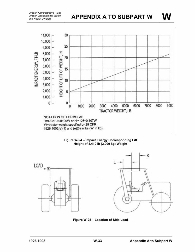
H = Vertical height of lift of 4,410-lb (2,000-kg) weight, in. (H', mm). The weight shall be pulled back so that the height of its center of gravity above the point of impact is defined as follows: H = 4.92 + 0.00190 W (H' = 125 + 0.107 W') (see Figure W-24).
(k) Source of standard. The standard in this section is derived from, and restates, in part, Society of Automotive Engineers ("SAE") standard J334a-1970 ("Protective frame test procedures and performance requirements"). The SAE standard appears in the 1971 SAE Handbook, which may be examined at any OSHA regional office.
[61 FR 9227, March 7, 1996; 70 FR 76985, Dec. 29, 2005] Stat. Auth.: ORS 654.025(2) and 656.726(4). Stats, Implemented: ORS 654.001 through 654.295. Hist: APD Admin. Order 4-1989, f. 3/31/89, ef. 5/1/89 (temp). APD Admin. Order 8-1989, f. 7/7/89, ef. 7/7/89 (perm). OR-OSHA Admin. Order 4-1997, f. 4/2/97, ef. 4/2/97. OR-OSHA Admin. Order 5-2006, f. 8/7/06, ef. 1/1/07.
Oregon Administrative Rules Oregon Occupational Safety and Health Division
OVERHEAD PROTECTION FOR OPERATORS OF AGRICULTURAL & INDUSTRIAL TRACTORS USED IN
CONSTRUCTION W
1926.1003 W-21 (a)(1) – (c)(3)
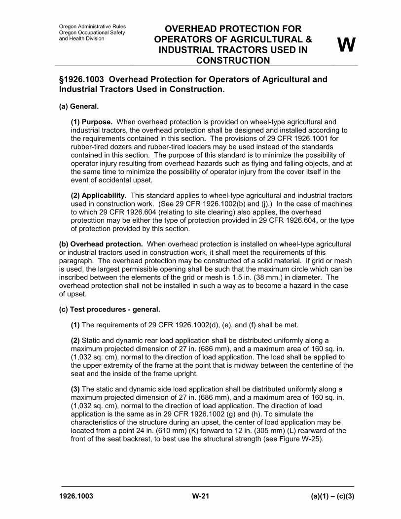
§1926.1003 Overhead Protection for Operators of Agricultural and Industrial Tractors Used in Construction. (a) General.
(1) Purpose. When overhead protection is provided on wheel-type agricultural and industrial tractors, the overhead protection shall be designed and installed according to the requirements contained in this section. The provisions of 29 CFR 1926.1001 for rubber-tired dozers and rubber-tired loaders may be used instead of the standards contained in this section. The purpose of this standard is to minimize the possibility of operator injury resulting from overhead hazards such as flying and falling objects, and at the same time to minimize the possibility of operator injury from the cover itself in the event of accidental upset.
(2) Applicability. This standard applies to wheel-type agricultural and industrial tractors used in construction work. (See 29 CFR 1926.1002(b) and (j).) In the case of machines to which 29 CFR 1926.604 (relating to site clearing) also applies, the overhead protecttion may be either the type of protection provided in 29 CFR 1926.604, or the type of protection provided by this section.
(b) Overhead protection. When overhead protection is installed on wheel-type agricultural or industrial tractors used in construction work, it shall meet the requirements of this paragraph. The overhead protection may be constructed of a solid material. If grid or mesh is used, the largest permissible opening shall be such that the maximum circle which can be inscribed between the elements of the grid or mesh is 1.5 in. (38 mm.) in diameter. The overhead protection shall not be installed in such a way as to become a hazard in the case of upset.
(c) Test procedures - general.
(1) The requirements of 29 CFR 1926.1002(d), (e), and (f) shall be met.
(2) Static and dynamic rear load application shall be distributed uniformly along a maximum projected dimension of 27 in. (686 mm), and a maximum area of 160 sq. in. (1,032 sq. cm), normal to the direction of load application. The load shall be applied to the upper extremity of the frame at the point that is midway between the centerline of the seat and the inside of the frame upright.
(3) The static and dynamic side load application shall be distributed uniformly along a maximum projected dimension of 27 in. (686 mm), and a maximum area of 160 sq. in. (1,032 sq. cm), normal to the direction of load application. The direction of load application is the same as in 29 CFR 1926.1002 (g) and (h). To simulate the characteristics of the structure during an upset, the center of load application may be located from a point 24 in. (610 mm) (K) forward to 12 in. (305 mm) (L) rearward of the front of the seat backrest, to best use the structural strength (see Figure W-25).

W OVERHEAD PROTECTION FOR
OPERATORS OF AGRICULTURAL & INDUSTRIAL TRACTORS USED IN
CONSTRUCTION
Oregon Administrative Rules Oregon Occupational Safety
and Health Division
(d)(1) – (f)(3) W-22 1926.1003
(d) Drop test procedures.
(1) The same frame shall be subjected to the drop test following either the static or dynamic test.
(2) A solid steel sphere or material of equivalent spherical dimension weighing 100 lb (45.4 kg) shall be dropped once from a height 10 ft (3.08 m) above the overhead cover.
(3) The point of impact shall be on the overhead cover at a point within the zone of protection as shown in Figure W-26, which is furthest removed from major structural members.
(e) Crush test procedure.
(1) The same frame shall be subjected to the crush test following the drop test and static or dynamic test.
(2) The test load shall be applied as shown in Figure W-27, with the seat positioned as specified in 29 CFR 1926.1002(d)(4). Loading cylinders shall be mounted pivotally at both ends. Loads applied by each cylinder shall be equal within two percent, and the sum of the loads of the two cylinders shall be two times the tractor weight as set forth in 29 CFR 1926.1002(e)(1). The maximum width of the beam illustrated in Figure W-27 shall be 6 in. (152 mm).
(f) Performance requirements.
(1) General. The performance requirements set forth in 29 CFR 1926.1002(i)(2), (3), and (4) shall be met.
(2) Drop test performance requirements.
(i) Instantaneous deformation due to impact of the sphere shall not enter the protected zone as illustrated in Figures W-25, W-26, and W-28.
(ii) In addition to the dimensions set forth in 29 CFR 1926.1002(i)(1)(i), the following dimensions apply to Figure W-28:
H = 17.5 in. (444 mm); and
J = 2 in. (50.8 mm), measured from the outer periphery of the steering wheel.
(3) Crush test performance requirements. The protected zone as described in Figure W-28 must not be violated.

Oregon Administrative Rules Oregon Occupational Safety and Health Division
OVERHEAD PROTECTION FOR OPERATORS OF AGRICULTURAL & INDUSTRIAL TRACTORS USED IN
CONSTRUCTION W
1926.1003 W-23 (g)
(g) Source of standard. This standard is derived from, and restates, in part, the portions of Society of Automotive Engineers ("SAE") standard J167-1970 ("Protective frame with overhead protection -- test procedures and performance requirements"), which pertain to overhead protection requirements. The SAE standard appears in the 1971 SAE Handbook, which may be examined at any OSHA regional office.
[61 FR 9227, March 7, 1996; 70 FR 76987, Dec. 29, 2005]
Stat. Auth.: ORS 654.025(2) and 656.726(4). Stats, Implemented: ORS 654.001 through 654.295. Hist: APD Admin. Order 8-1989, f. 7/7/89, ef. 7/7/89. APD Admin. Order 4-1997, f. 4/2/97, ef. 4/2/97. OR-OSHA Admin. Order 5-2006, f. 8/7/06, ef. 1/1/07.

W Oregon Administrative Rules Oregon Occupational Safety
and Health Division
W-24

Oregon Administrative Rules Oregon Occupational Safety and Health Division APPENDIX A TO SUBPART W W
1926.1003 W-25 Appendix A to Subpart W
Appendix A to Subpart W
Figure W-14 – Typical Frame Configuration

W APPENDIX A TO SUBPART W Oregon Administrative Rules Oregon Occupational Safety
and Health Division
Appendix A to Subpart W W-26 1926.1003
Figure W-15 – Side Overturn Bank and Ramp

Oregon Administrative Rules Oregon Occupational Safety and Health Division APPENDIX A TO SUBPART W W
1926.1003 W-27 Appendix A to Subpart W
Figure W-16 – Side Load Application
Figure W-17 – Rear Load Application

W APPENDIX A TO SUBPART W Oregon Administrative Rules Oregon Occupational Safety
and Health Division
Appendix A to Subpart W W-28 1926.1003
Figure W-18 – Method of Measuring Instantaneous Deflection
Figure W-19 – Typical L-D Diagram

Oregon Administrative Rules Oregon Occupational Safety and Health Division APPENDIX A TO SUBPART W W
1926.1003 W-29 Appendix A to Subpart W
Figure W-20 – Typical Modified LM-DM Diagram

W APPENDIX A TO SUBPART W Oregon Administrative Rules Oregon Occupational Safety
and Health Division
Appendix A to Subpart W W-30 1926.1003
Figure W-21 – Pendulum

Oregon Administrative Rules Oregon Occupational Safety and Health Division APPENDIX A TO SUBPART W W
1926.1003 W-31 Appendix A to Subpart W
Figure W-22 – Method of Impact From Rear

W APPENDIX A TO SUBPART W Oregon Administrative Rules Oregon Occupational Safety
and Health Division
Appendix A to Subpart W W-32 1926.1003
Figure W-23 – Method of Impact From Side
Oregon Administrative Rules Oregon Occupational Safety and Health Division APPENDIX A TO SUBPART W W
1926.1003 W-33 Appendix A to Subpart W
Figure W-24 – Impact Energy Corresponding Lift
Height of 4,410 lb (2,000 kg) Weight
Figure W-25 – Location of Side Load

W APPENDIX A TO SUBPART W Oregon Administrative Rules Oregon Occupational Safety
and Health Division
Appendix A to Subpart W W-34 1926.1003
Figure W-26 – Zone of Protection for Drop Test

Oregon Administrative Rules Oregon Occupational Safety and Health Division APPENDIX A TO SUBPART W W
- END OF DOCUMENT - 1926.1003 W-35 Appendix A to Subpart W
Figure W-27 – Method of Load Application for Crush Test
Figure W-28 – Protected Zone During Crush and Drop Test
Stat. Auth.: ORS 654.025(2) and 656.726(4). Stats. Implemented: ORS 654.001 through 654.295 OR-OSHA Admin. Order 5-2006, f. 8/7/06, ef. 1/1/07.

W Oregon Administrative Rules Oregon Occupational Safety
and Health Division
W-36