DIVISION 10.1 - MATERIALS - NCDOT · Web viewFurnishing data to verify that the approved...
176
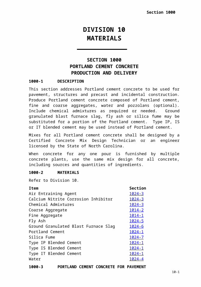
Section 1000 DIVISION 10 MATERIALS SECTION 1000 PORTLAND CEMENT CONCRETE PRODUCTION AND DELIVERY 1000-1 DESCRIPTION This section addresses Portland cement concrete to be used for pavement, structures and precast and incidental construction. Produce Portland cement concrete composed of Portland cement, fine and coarse aggregates, water and pozzolans (optional). Include chemical admixtures as required or needed. Ground granulated blast furnace slag, fly ash or silica fume may be substituted for a portion of the Portland cement. Type IP, IS or IT blended cement may be used instead of Portland cement. Mixes for all Portland cement concrete shall be designed by a Certified Concrete Mix Design Technician or an engineer licensed by the State of North Carolina. When concrete for any one pour is furnished by multiple concrete plants, use the same mix design for all concrete, including sources and quantities of ingredients. 1000-2 MATERIALS Refer to Division 10. Item Section Air Entraining Agent 1024-3 Calcium Nitrite Corrosion Inhibitor 1024-3 Chemical Admixtures 1024-3 Coarse Aggregate 1014-2 Fine Aggregate 1014-1 Fly Ash 1024-5 Ground Granulated Blast Furnace Slag 1024-6 Portland Cement 1024-1 Silica Fume 1024-7 Type IP Blended Cement 1024-1 Type IS Blended Cement 1024-1 Type IT Blended Cement 1024-1 Water 1024-4 1000-3 PORTLAND CEMENT CONCRETE FOR PAVEMENT 10-1
Transcript of DIVISION 10.1 - MATERIALS - NCDOT · Web viewFurnishing data to verify that the approved...
Section 1000
DIVISION 10MATERIALS
SECTION 1000PORTLAND CEMENT CONCRETE
PRODUCTION AND DELIVERY1000-1 DESCRIPTION
This section addresses Portland cement concrete to be used for pavement, structures and precast and incidental construction. Produce Portland cement concrete composed of Portland cement, fine and coarse aggregates, water and pozzolans (optional). Include chemical admixtures as required or needed. Ground granulated blast furnace slag, fly ash or silica fume may be substituted for a portion of the Portland cement. Type IP, IS or IT blended cement may be used instead of Portland cement.
Mixes for all Portland cement concrete shall be designed by a Certified Concrete Mix Design Technician or an engineer licensed by the State of North Carolina.
When concrete for any one pour is furnished by multiple concrete plants, use the same mix design for all concrete, including sources and quantities of ingredients.
1000-2 MATERIALS
Refer to Division 10.
Item SectionAir Entraining Agent 1024-3Calcium Nitrite Corrosion Inhibitor 1024-3Chemical Admixtures 1024-3Coarse Aggregate 1014-2Fine Aggregate 1014-1Fly Ash 1024-5Ground Granulated Blast Furnace Slag 1024-6Portland Cement 1024-1Silica Fume 1024-7Type IP Blended Cement 1024-1Type IS Blended Cement 1024-1Type IT Blended Cement 1024-1Water 1024-4
1000-3 PORTLAND CEMENT CONCRETE FOR PAVEMENT
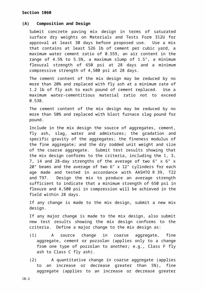
(A)Composition and Design
Submit concrete paving mix design in terms of saturated surface dry weights on Materials and Tests Form 312U for approval at least 30 days before proposed use. Use a mix that contains at least 526 lb of cement per cubic yard, a maximum water cement ratio of 0.559, an air content in the range of 4.5% to 5.5%, a maximum slump of 1.5", a minimum flexural strength of 650 psi at 28 days and a minimum compressive strength of 4,500 psi at 28 days.
The cement content of the mix design may be reduced by no more than 20% and replaced with fly ash at a minimum rate of 1.2 lb of fly ash to each pound of cement replaced. Use a maximum water-cementitious material ratio not to exceed 0.538.
10-1
Section 1060
The cement content of the mix design may be reduced by no more than 50% and replaced with blast furnace slag pound for pound.
Include in the mix design the source of aggregates, cement, fly ash, slag, water and admixtures; the gradation and specific gravity of the aggregates; the fineness modulus of the fine aggregate; and the dry rodded unit weight and size of the coarse aggregate. Submit test results showing that the mix design conforms to the criteria, including the 1, 3, 7, 14 and 28-day strengths of the average of two 6" x 6" x 20" beams and the average of two 6" x 12" cylinders for each age made and tested in accordance with AASHTO R 39, T22 and T97. Design the mix to produce an average strength sufficient to indicate that a minimum strength of 650 psi in flexure and 4,500 psi in compression will be achieved in the field within 28 days.
If any change is made to the mix design, submit a new mix design.
If any major change is made to the mix design, also submit new test results showing the mix design conforms to the criteria. Define a major change to the mix design as:
(1) A source change in coarse aggregate, fine aggregate, cement or pozzolan (applies only to a change from one type of pozzolan to another; e.g., Class F fly ash to Class C fly ash).
(2) A quantitative change in coarse aggregate (applies to an increase or decrease greater than 5%), fine aggregate (applies to an increase or decrease greater than 5%), water (applies to an increase only), cement (applies to a decrease only), or pozzolan (applies to a decrease only).
Where concrete with a higher slump for hand methods of placing and finishing is necessary, submit an adjusted mix design for approval to provide a maximum slump of 3" and to maintain the water-cementitious material ratio established by the original mix design.
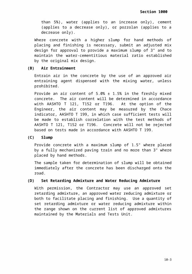
(B)Air Entrainment
Entrain air in the concrete by the use of an approved air entraining agent dispensed with the mixing water, unless prohibited.
Provide an air content of 5.0% ± 1.5% in the freshly mixed concrete. The air content will be determined in accordance with AASHTO T 121, T152 or T196. At the option of the Engineer, the air content may be measured by the Chace indicator, AASHTO T 199, in which case sufficient tests will be made to establish correlation with the test methods of AASHTO T 121, T152 or T196. Concrete will not be rejected based on tests made in accordance with AASHTO T 199.
(C)Slump
Provide concrete with a maximum slump of 1.5" where placed by a fully mechanized paving train and no more than 3" where placed by hand methods.
The sample taken for determination of slump will be obtained immediately after the concrete has been discharged onto the road.
(D)Set Retarding Admixture and Water Reducing Admixture
With permission, the Contractor may use an approved set retarding admixture, an approved water reducing admixture or both to facilitate placing and finishing. Use a quantity of set retarding admixture or water reducing admixture within the range shown on the current list of approved admixtures maintained by the Materials and Tests Unit.
10-2
Section 1000
(E)Contractor’s Responsibility for Process Control
Before or at the preconstruction conference, submit a plan detailing the process control and the type and frequency of testing and inspection necessary to produce concrete that meets the Specifications. During all batching and delivery operations assign a Certified Concrete Batch Technician on site whose sole duty is to supervise the production and control of the concrete. This duty includes the following:
(1) Tests and inspections necessary to maintain the stockpiles of aggregates in an unsegregated and uncontaminated condition.
(2) Calibration of admixture dispensing systems, weighing systems and water gauges.
(3) Tests and adjustments of mix proportions for moisture content of aggregates.
(4) Mixer performance tests before reducing mixing time of central mix plant to less than 90 seconds and at other times when deemed necessary by the Engineer.
(5) Verifying the actual mixing time of the concrete after all materials are introduced into the mixer at the beginning of paving operations and at least once each month.
(6) Testing all vibrators.
(7) Tests necessary to document the slump and air content of the mix produced. Determine air content at least twice each day.
(8) Tests for depth of the pavement in the plastic state.
(9) Furnishing data to verify that the approved theoretical cement content has been met at intervals not to exceed 50,000 sy of pavement.
(10) Signing all plant reports, batch tickets and delivery tickets.
The Department certifies technicians who satisfactorily complete examinations prepared and administered by the Division of Highways.
Perform all test procedures in compliance with the appropriate articles of Section 1000.
Tests may be witnessed by the Engineer. Document the results of all tests and inspections and make a copy available to the Engineer upon request. Take prompt action to correct conditions that have resulted in or could result in the submission of materials, products, or completed construction that do not conform to the Standard Specifications.
(F)Contractor Not Relieved of Responsibility for End Result
The Contractor will not be relieved of his obligation to produce a uniform pavement meeting Specifications by reason of:
(1) The acceptance or approval by the Engineer of the concrete mix design or any adjustments;
(2) Compliance with the concrete mix design and compliance with the testing requirements and other process control requirements by the Contractor; or
(3) The failure of the Engineer to perform any tests in the process control, nor the performance of any tests in the process control that indicate compliance with the Specifications.
1000-4 PORTLAND CEMENT CONCRETE FOR STRUCTURES AND INCIDENTAL CONSTRUCTION
(A)Composition and Design
Provide the class of concrete required by the contract.
10-3

Section 1060
Submit proposed concrete mix designs for each class of concrete to be used in the work. Mix proportions shall be determined by a testing laboratory approved by the Department. Base mix designs on laboratory trial batches that meet Table 1000-1 and this section.
Submit mix designs in terms of saturated surface dry weights on Materials and Tests Form 312U at least 35 days before proposed use. Adjust batch proportions to compensate for surface moisture contained in the aggregates at the time of batching. Changes in the saturated surface dry mix proportions will not be permitted unless revised mix designs have been submitted to the Engineer and approved.
Accompany Materials and Tests Form 312U with a listing of laboratory test results of aggregate gradation, air content, slump and compressive strength. List the compressive strength of at least three 6" x 12" or 4" x 8" cylinders at the age of 7 and 28 days.
Perform laboratory tests in accordance with the following test procedures:
Property Test MethodAggregate Gradation AASHTO T 27Air Content AASHTO T 152Slump AASHTO T 119Compressive Strength AASHTO T 22 and T23
The Engineer will review the mix design for compliance with the Specifications and notify the Contractor as to its acceptability. Do not use a mix until written notice has been received. Acceptance of the mix design does not relieve the Contractor of his responsibility to furnish a product that meets the contract. Upon written request from the Contractor, a mix design accepted and used satisfactorily on any Department project may be accepted for use on other projects.
(B)Air Entrainment
Entrain air in the concrete unless otherwise indicated in the plans or in the Specifications. Add an air entraining agent at the time of mixing to produce an air content in the freshly mixed concrete of 6.0% ± 1.5% when tested at the job site. Determine the air content in accordance with AASHTO T 121, T152 or T196. Measurement of air content may also be performed by the Chace indicator in accordance with AASHTO T 199, in which case sufficient tests will be made in accordance with AASHTO T 121, T152 or T196 to establish correlation with the Chace indicator. Concrete for structures will not be rejected based on tests made in accordance with AASHTO T 199. Concrete for incidental construction may be rejected based on an average of 3 or more tests made in accordance with AASHTO T 199.
Air entraining agent may be added at the job site when permitted by the Engineer.
(C)Strength of Concrete
The compressive strength of the concrete will be considered the average compressive strength test results of two 6" x 12" cylinders, or two 4" x 8" cylinders if the aggregate size is not larger than size 57 or 57M. Make cylinders in accordance with AASHTO T 23 from the concrete delivered to the work. Make cylinders at such frequencies as the Engineer may determine and cure them in accordance with AASHTO T 23 as modified by the Department. Copies of these modified test procedures are available upon request from the Materials and Tests Unit.
When the average compressive strength of the concrete test cylinders is less than the minimum strength specified in Table 1000-1 and the Engineer determines if the concrete strength will be acceptable. When the Engineer determines average cylinder strength is below the specification, the in-place concrete will be tested. Based on these test results,
10-4

Section 1000
the concrete will either be accepted with no reduction in payment or accepted at a reduced unit price or rejected as set forth in Article 105-3.
(D)Temperature Requirements
The concrete temperature at the time of placement shall be not less than 50°F nor more than 95°F except where other temperatures are required by Articles 420-4, 420-7, 420-14 and 420-15.
Do not place concrete without permission when the air temperature measured at the location of the concrete operation in the shade away from artificial heat is below 35°F.
When such permission is granted, uniformly heat the aggregates and/or water to a temperature not higher than 150°F. Heated concrete shall be between 55°F and 80°F at the time of placement.
TABLE 1000-1REQUIREMENTS FOR CONCRETE
Cla
ss o
f Con
cret
e
Min
. Com
p.
Stre
ngth
Maximum Water-Cement Ratio
Consistency Max. Slump Cement Content
Air-Entrained Concrete
Non Air-Entrained Concrete
Vib
rate
d
Non
- Vib
rate
d
Vibrated Non- Vibrated
Rounded
Aggre-gate
Angular
Aggre-gate
Rounded
Aggre-gate
Angular
Aggre-gate
Min. Max. Min. Max.
Units psi inch inch lb/cy lb/cy lb/cy lb/cy
AA 4,500 0.381 0.426 - - 3.5 - 639 715 - -AA Slip
Form 4,500 0.381 0.426 - - 1.5 - 639 715 - -
Drilled Pier 4,500 - - 0.450 0.450 -
5-7 dry
7-9 wet
- - 640 800
A 3,000 0.488 0.532 0.550 0.594 3.5 4 564 677 602 602B 2,500 0.488 0.567 0.559 0.630 2.5 4 508 610 545 654
B Slip Formed 2,500 0.488 0.567 - - 1.5 - 508 610 - -
Sand Light-weight
4,500 - 0.420 - - 4 - 715 715 - -
Latex Modifie
d
3,000 7 day
0.400 0.400 - - 6 - 658 658 - -
Flowable Fill
excavatable
150 max.
at 56 day
s
as needed
as needed
as needed
as needed - Flow-
able - - 40 100
Flowable Fillnon-
excavatable
125 as needed
as needed
as needed
as needed - Flow-
able - - 100as
needed
Pavement
4,500 design,
field
650 flexural, design only
0.559 0.559 - -
1.5 slip form
3.0 hand place
- 526 - - -
Precast See Table
as needed
as needed
- - 6 as neede
as neede
as neede
as neede
as neede
10-5

Section 1060
1077-1 d d d d d
Prestressper
contract
See Table
1078-1
See Table 1078-
1
- - 8 - 564as
needed
- -
(E) Elapsed Time for Placing Concrete
Regulate the delivery so the maximum interval between the placing of batches at the work site does not exceed 20 minutes. Place concrete before exceeding the times in Table 1000-2. Measure the elapsed time as the time between adding the mixing water to the mix and placing the concrete.
TABLE 1000-2ELAPSED TIME FOR PLACING CONCRETE
Air or Concrete TemperatureWhichever is Higher
Maximum Elapsed TimeNo Retarding
AdmixtureUsed
RetardingAdmixture
Used90°F or above 30 minutes 1 hr. 15 minutes
80°F through 89°F 45 minutes 1 hr. 30 minutes79°F or belowA 60 minutes 1 hr. 45 minutes
70°F through 79°FB 60 minutes 1 hr. 45 minutes69°F or belowB 1 hr. 30 minutes 2 hr. 15 minutes
A. Applicable to Class AA, A and Drilled Pier concrete.B. Applicable to Class B concrete.
(F)Use of Set Retarding Admixtures
Use an approved set retarding admixture in all concrete placed in the superstructure of bridges such that the concrete will remain workable until the entire operation of placing and finishing, including corrective measures, if necessary, has been completed. The Engineer may waive the use of set retarding admixture when conditions clearly indicate that it is not needed.
Other structural concrete may contain an approved set retarding admixture when permitted by the Engineer.
Use a quantity of set retarding admixture within the range shown on the current list of approved admixtures issued by the Materials and Tests Unit.
(G)Use of Water Reducing Admixtures
By permission of the Engineer, the Contractor may use an approved water reducing admixture to facilitate placing and finishing.
Use a quantity of water reducing admixture within the range shown on the current list of approved admixtures issued by the Materials and Tests Unit.
(H)Use of Calcium Chloride
Calcium chloride may be used as a set accelerating agent where permitted by the Engineer. Use one pound of calcium chloride per 100 lb of cement except where lesser amounts are directed. Do not use calcium chloride where steel reinforcement, metal conduit or other metals will be in contact with the concrete. Do not use calcium chloride in concrete that has a temperature higher than 70°F, or when the air temperature is greater than 70°F. Provide cold weather protection for concrete containing calcium chloride in the same manner as is provided for concrete without calcium chloride.
10-6

Section 1000
Use calcium chloride in liquid form. Use a solution of one pound or less of calcium chloride per one quart of water and mix well. To avoid incompatibility with other additives, add the calcium chloride to the batch after all other ingredients have been put into the mixer.
(I) Use of Fly Ash
Use Table 1000-3 to determine the maximum allowable water-cementitious material (cement + fly ash) ratio for the classes of concrete listed. For all other classes, the maximum water-cementitious material ratio will be the same as the water-cement ratio listed in Table 1000-1.
TABLE 1000-3MAXIMUM WATER-CEMENTITIOUS MATERIAL RATIO
Class of Concrete Rounded Aggregate Angular AggregateAA and AA Slip Form .366 .410
A .469 .512B and B Slip Form .469 .545
Pavement .538 .538
(J) Use of Ground Granulated Blast Furnace Slag
For mixes that contain cement and ground granulated blast furnace slag, the water-cementitious ratio (cement and slag) shall not exceed the water-cement ratio shown in Table 1000-1.
(K)Use of Calcium Nitrite Corrosion Inhibitor
Units with calcium nitrite in a quantity less than specified are subject to rejection. Furnish concrete cylinders to the Engineer, in a quantity to be specified, to verify the concentrations of calcium nitrite in hardened concrete. Concrete that fails to contain calcium nitrite at the required concentrations as tested is subject to rejection. Use air-entraining, water-reducing and/or set-controlling admixtures compatible with calcium nitrite solutions. Strictly adhere to the manufacturer’s written recommendations regarding the use of admixtures, including storage, transportation and method of mixing. If preferred, use calcium nitrite, which acts as an accelerator, in conjunction with a retarder to control the set of concrete, as per the manufacturer’s recommendation. Add an approved calcium nitrite corrosion inhibitor (30% solids) to the concrete mix at the batch plant for the bridge elements identified by the plan notes. Use the inhibitor at a minimum rate of 3.0 gal/cy. Ensure that the hardened concrete contains at least 5.1 lb/cy nitrite (NO2) when tested in accordance with Materials and Tests Method Chem. C-20.0. The preceding paragraph does not apply to concrete used in prestressed concrete members. Concrete used in prestressed concrete members shall be tested in accordance with Subarticle 1078-4(G).
1000-5 HIGH EARLY STRENGTH PORTLAND CEMENT CONCRETE
Use high early strength Portland cement concrete when required by contract. When not required, it may be used at the Contractor’s option with approval of the Engineer.
For all classes of concrete, high early strength concrete may be produced by using Type III Portland cement. To produce high early strength concrete with regular cement, use a higher class of concrete as follows:
For Class A and Class B, use Class AA with a cement content of at least 677 lb/cy. For Class B slip form, use Class AA slip form with a cement content of at least 677 lb/cy. Other classes that lend themselves to high early strength with regular cement will be reviewed by the Engineer on a case-by-case basis.
10-7

Section 1060
1000-6 FLOWABLE FILL
Flowable fill consists of Portland cement, water, pozzolan and/or fine aggregate and, optionally, concrete admixtures.
Submit the proposed mix design on Materials and Tests Form 312U at least 35 days before use. Use a testing laboratory approved by the Department to determine mix proportions based on laboratory trial batches meeting Table 1000-1.
State on Form 312U the intended use of the material. Accompany Form 312U with a listing of compressive strength of at least three 4" x 8" cylinders at the age of 28 or 56 days, depending on whether the mix is to be excavated or not. Air cure the cylinders during the entire period before testing. The Engineer will advise the Contractor in writing of the acceptability of the mix design.
1000-7 LATEX MODIFIED CONCRETE
(A)Materials
Refer to Division 10.
Item SectionCoarse Aggregate, standard size No. 78M 1014-2Fine Aggregate 1014-1Portland Cement 1024-1Type IP Blended Cement 1024-1Type IS Blended Cement 1024-1Type IT Blended Cement 1024-1Water 1024-4
Do not use Type III high early strength cement.
Use a formulated latex admixture that is a non-hazardous, film forming and polymeric emulsion in water and is homogeneous and uniform in composition. Add all stabilizers at the point of manufacture.
Use a latex modifier conforming to Table 1000-4.
TABLE 1000-4PROPERTIES OF LATEX MODIFIER FOR CONCRETEProperty Requirement
Polymer TypeStyrene Butadiene:68 ± 4% Styrene
32 ± 4% ButadieneAverage Polymer Particle Size 1500 to 2500 Angstroms
Emulsion Stabilizers Anionic and non-ionic surfactantsPercent Solids 46.5% to 49.0%
Weight per gallon at 75°F 8.40 to 8.60 lbpH 9.5 to 11.0
Shelf Life 2 YearsColor White
Provide a Type 5 material certification for each load of latex emulsion admixture in accordance with Article 106-3. Test admixture samples to verify compliance with the requirements before use. Allow 7 days for sampling and testing after delivery to the project.
Do not allow the temperature of latex emulsion admixture to fall below 35°F at any time or exceed 85°F after delivery to the project.
10-8

Section 1000
For latex emulsion that has been in storage, use a transfer pump and lines to recirculate it before using.
For latex modified concrete, use a workable mixture that meets Table 1000-5.
Measure the slump 4 to 5 minutes after discharge from the mixer.
Submit the latex modified concrete mix design, completed by the latex emulsion manufacturer, to the Engineer for review.
TABLE 1000-5PROPERTIES OF LATEX MODIFIED CONCRETEProperty Requirement
Cement Content, lb/cy 658 min.Latex Emulsion Admixture, gal/cy 24.5 min.
Air Content of Plastic Mix, % 3.5 - 6.5Slump, inches 3 - 6
% Fine Aggregate as percent of total aggregate by weight 50 - 55
7 day Compressive Strength, psi 3,000 min.Water-Cement Ratio by weight 0.40 max.
(B)Equipment
Before beginning any work, obtain approval for all equipment to be used for deck preparation, mixing, placing, finishing and curing the latex modified concrete.
Use sandblasting equipment capable of removing all clay, salt deposits, oil and grease deposits and all other foreign matter. Provide traps or separators to remove oil and water from the compressed air. Use traps or separators of adequate size and drain them periodically during operations. For proportioning and mixing, use self-contained, mobile and continuously mixing equipment that meets the following requirements:
Use a self-propelled mixer that is capable of carrying sufficient unmixed dry, bulk cement, sand, coarse aggregate, latex modifier and water to produce at least 6 cy of concrete on site.
Use a mixer that is capable of positive measurement of cement introduced into the mix. Use a recording meter that is visible at all times and equipped with a ticket printout to indicate the quantity of cement.
Calibrate the mixers to accurately proportion the specified mix. Before placing latex modified concrete, perform calibration and yield tests under the Engineer’s supervision in accordance with the Department’s written instructions. Copies of these written instructions are available from the Materials and Tests Unit. Perform the calibration and yield tests using the material to be used on the project. Recalibrate the mixer after any major maintenance operation on the mixer, anytime the source of materials changes or as directed. Furnish all materials and equipment necessary to perform the calibrations and yield tests.
Use a mixer that controls the flow of water and latex emulsion into the mix. Measure the flow rate of water and the latex emulsion with a calibrated flowmeter coordinated with both the cement and aggregate feeding mechanisms and the mixer. Adjust the flow rate, as necessary, to control the slump and ensure that the water-cement ratios are met. In addition to flowmeters, use mixers with accumulative water and latex meters capable of indicating the number of gallons, to the nearest 0.1 gallon, introduced into the mixer. Filter water and latex with a suitable mesh filter before it flows through the accumulative water and latex meters.
10-9

Section 1060
Calibrate the mixer to automatically proportion and blend all components of the indicated composition on a continuous or intermittent basis as the finishing operation requires. Provide a mixer that discharges mixed material through a conventional chute and is capable of spraying water over the placement width as it moves ahead to ensure that the surface to be overlaid is wet before receiving the modified material.
Mount a tachometer on the unit to indicate the drive shaft speed.
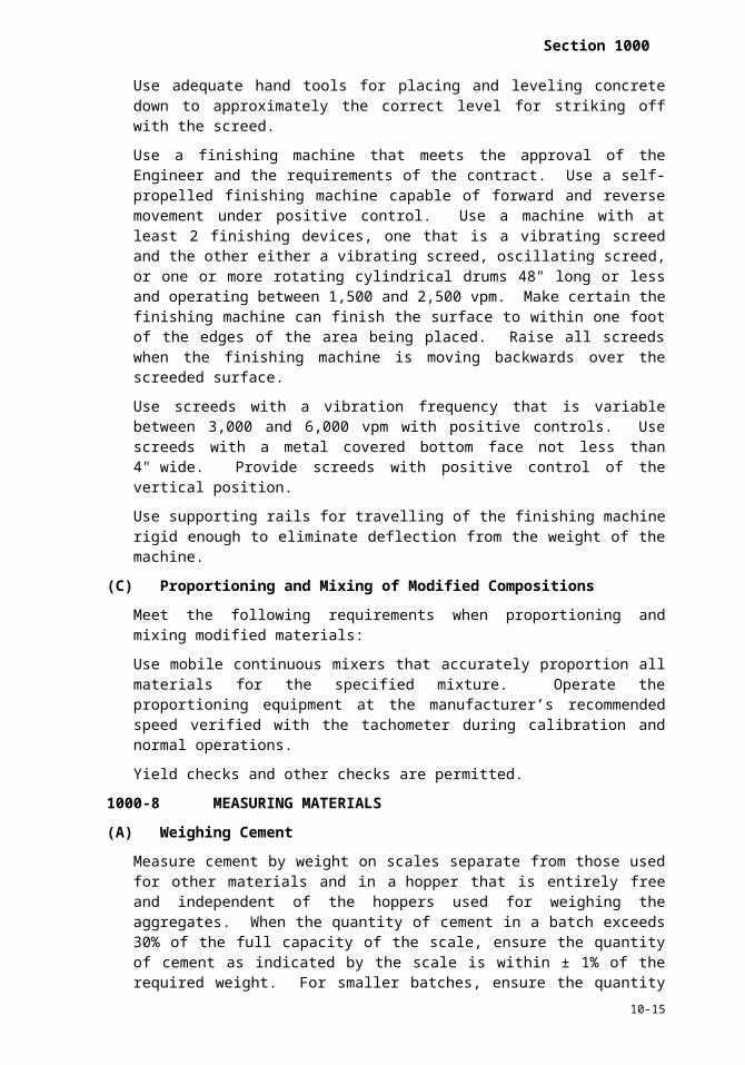
Use adequate hand tools for placing and leveling concrete down to approximately the correct level for striking off with the screed.
Use a finishing machine that meets the approval of the Engineer and the requirements of the contract. Use a self-propelled finishing machine capable of forward and reverse movement under positive control. Use a machine with at least 2 finishing devices, one that is a vibrating screed and the other either a vibrating screed, oscillating screed, or one or more rotating cylindrical drums 48" long or less and operating between 1,500 and 2,500 vpm. Make certain the finishing machine can finish the surface to within one foot of the edges of the area being placed. Raise all screeds when the finishing machine is moving backwards over the screeded surface.
Use screeds with a vibration frequency that is variable between 3,000 and 6,000 vpm with positive controls. Use screeds with a metal covered bottom face not less than 4" wide. Provide screeds with positive control of the vertical position.
Use supporting rails for travelling of the finishing machine rigid enough to eliminate deflection from the weight of the machine.
(C)Proportioning and Mixing of Modified Compositions
Meet the following requirements when proportioning and mixing modified materials:
Use mobile continuous mixers that accurately proportion all materials for the specified mixture. Operate the proportioning equipment at the manufacturer’s recommended speed verified with the tachometer during calibration and normal operations.
Yield checks and other checks are permitted.
1000-8 MEASURING MATERIALS
(A)Weighing Cement
Measure cement by weight on scales separate from those used for other materials and in a hopper that is entirely free and independent of the hoppers used for weighing the aggregates. When the quantity of cement in a batch exceeds 30% of the full capacity of the scale, ensure the quantity of cement as indicated by the scale is within ± 1% of the required weight. For smaller batches, ensure the quantity of cement as indicated by the scale be not less than the required amount or more than 4% in excess. Equip all beam type scales with a tare beam.
(B)Weighing Aggregates
Measure aggregates by weight. Base batch weights on saturated surface dry materials and which are the required weights plus the total weight of surface moisture contained in the aggregates. Ensure the individual aggregates, as weighed, are within ± 2% of the required weights.
(C)Water
Measure water by volume or by weight. Ensure the quantity of water measured is within ± 1% of the required amount.
(D)Admixture Dispensing Systems
10-10

Section 1000
Provide a separate dispensing system with separate fill and discharge lines for each type of admixture to be used, except that admixtures may be measured and introduced into the mix manually if approval has been obtained. Ensure each system is capable of measuring, displaying and discharging the required amount of admixture into the mix. Keep dispensing systems clean and in good operating condition. Use a dispensing system that is either:
(1) Manually operated, self contained; or
(2) Semi-automatic or automatic, self-contained; or
(3) Interfaced to operate automatically with the concrete batching control panel.
Have the admixture dispenser dispense the required quantity of admixture for each concrete batch within an accuracy of ± 3%. Check the accuracy of the dispenser as provided below. Check the accuracy at the point of discharge, or through a bypass valve suitable for obtaining a calibrated sample of admixture and at the volumes normally used for one half mixer capacity and for full mixer capacity. Determine the accuracy at the time of installation and check daily during the early part of each day’s operation.
Include in each system a graduated measuring unit into which the admixture is batched to permit a quick visual check of accuracy before its discharge. Ensure the measuring unit is clearly graduated and be of sufficient size to hold the maximum anticipated dose for one batch. Clearly mark the measuring unit for the type of admixture to be used.
Control the discharge sequence so an admixture will not be brought into contact with raw cement or another admixture before being diluted through contact with the mixing water in the mixer. Where 2 types of admixtures are being used, do not discharge them into the mix simultaneously. Add the air entraining agent with the first addition of water and add any other chemical admixture with the final addition of water, unless otherwise permitted.
Construct the discharge lines to completely empty after each cycle. Locate the admixture dispensing systems so the batching plant operator will have a visual verification of the actual quantity of admixture batched.
Use air entraining admixtures in accordance with the manufacturer’s recommendations and in such quantity to provide the specified air content in freshly mixed concrete. Use a quantity of set retarding admixture and of water reducing admixture per 100 lb of cement that is within the range recommended on the current list of approved admixtures issued by the Materials and Tests Unit.
1000-9 BATCHING PLANT
(A)General
Plants located on the Department rights of way shall conform to Article 107-3.
Have ready mixed concrete plants inspected and approved by the Department before they are used to produce concrete, either paving, structural or incidental, for the project. Plants shall meet all the applicable requirements of these Standard Specifications, and in addition, ensure each ready mix plant provides at least 3 acceptable truck mixers or truck agitators available for use. Use trucks that have an identifying number. Plants approved by the Department will be placed on a list of approved plants available to the Contractor. All plants will be subject to reinspection at intervals selected by the Engineer. Reapproval after each inspection will be contingent on continuing compliance with the Standard Specifications.
(B)Bins and Hoppers
10-11

Section 1060
Provide bins with separate compartments for fine aggregates and for each required size of coarse aggregate in the batching plant. Design each compartment to discharge efficiently and freely into the weighing hopper. Provide control so, as the quantity desired is being approached, the material may be added slowly and shut off with precision. Construct weighing hoppers to eliminate accumulation of tare materials and to discharge fully unless otherwise permitted. Provide a port or other opening for removing an overload of any one of the several materials from the hopper.
(C)Scales
Use either the beam type, load cell type or the springless dial type scales for weighing aggregates and cement. Ensure the minimum graduation on beam or dial is not more than 0.1% of the total capacity of the scale. Methods of weighing, other than beam or springless dial scales, may be approved by the Engineer provided they meet the required weighing tolerances. Ensure the scales are accurate within 0.5% under operating conditions. Make available ten 50 lb test weights at the plant for checking accuracy. Use test weights which meet the U.S. Bureau of Standards requirements for calibrating and testing equipment. Keep all exposed fulcrums, clevises and similar working parts of scales clean. When beam type scales are used, make provisions for indicating to the operator that the required load in the weighing hopper is being approached. Ensure the device indicates at least the last 50 lb of load and design it to give a positive indication of overload of the scales. During charging of the hopper, have all indicating devices in full view of the operator and provide convenient access to all controls. Ensure the indicating devices are in the immediate vicinity of the operator and easily readable by the operator.
(D)Water Measuring Devices
Use devices for measurement of the water which are readily adjustable and are capable of being set to deliver the required amount and cut off the flow automatically when this amount has been discharged. Under all operating conditions the device shall have accuracy within 1% of the quantity of water required for the batch. Arrange the device so variable pressures in the water supply line will not affect the measurements. Use measuring tanks of adequate capacity to furnish the maximum mixing water required and equip them with outside taps and valves to provide for checking their calibration unless other means are provided for readily and accurately determining the amounts in the tank.
1000-10 MIXERS AND AGITATORS
(A)General
Mixers are defined as equipment to mix concrete and may be stationary or truck mounted. Agitators are defined as equipment used to haul central mixed concrete and may be truck mixers or truck agitators. Provide a metal plate or plates attached to each mixer and agitator in a prominent place on which the manufacturer has plainly marked the mixing speed of the drum or paddles and the maximum capacity of the drum or container in terms of volume of mixed concrete. On truck mixers and agitators, show the manufacturer’s recommended agitating and mixing speed of rotation of the mixing drum or blades. Equip stationary mixers with an acceptable timing device that will not permit the batch to be discharged until the specified mixing time has elapsed. Equip truck mixers with counters to verify the number of revolutions of the drum or blades. Actuate the counters at the initial time the drums have reached mixing speed.
Examine mixers and agitators periodically for changes in condition due to accumulation of hard concrete or mortar, wear of blades or any other condition which decreases mixing efficiency. Mixers are unacceptable when the radial height or other dimension of the blade has worn below 90% of the original dimension. This radial height excludes any lips on the blade and is the height of the blade running perpendicular to the shell of the drum. Where such conditions are found, do not use the units until they are corrected.
10-12

Section 1000
Also examine mixers and agitators periodically for general mechanical condition, including water measuring and discharge apparatus, identifying number on trucks, condition of the blades, speed of rotation of the drum and condition of the drum.
(B)Mixer Capacity
Do not load truck mixers with concrete with more than 63% of the gross volume of the drum. Use mixers capable of combining the ingredients of the concrete into a thoroughly mixed and uniform mass and of discharging the concrete with a satisfactory degree of uniformity. Use stationary mixers, when loaded at the manufacturer’s guaranteed mixing capacity and the concrete mixed for the prescribed mixing time, capable of combining the ingredients of the concrete into a thoroughly mixed and uniform mass and discharging the concrete with satisfactory uniformity.
Use at least 20% of the rated mixing capacity as the minimum quantity of concrete permitted to be mixed or agitated in any mixer.
(C)Agitator Capacity
Load the agitator to not exceed 80% of the gross drum volume and have it be capable of maintaining the concrete in a thoroughly mixed and uniform mass and of discharging the concrete with a satisfactory degree of uniformity.
(D)Consistency Tests
The Engineer may, from time to time, make slump tests to measure consistency of the concrete. Take individual samples at approximately the 1/5th point, the midpoint and the 4/5th point of the load, using AASHTO T 119. Such tests will be made within 20 minutes of discharge of that portion of the load. If the results vary by more than 1" in slump, do not use the mixer or agitator unless the condition is corrected.
1000-11 MIXING AND DELIVERY
(A)General
Mix and deliver concrete to the site of the work by one of the following methods, except where other methods are approved. Maintain responsibility for controlling the materials and operations as to produce uniform concrete meeting Specifications requirements.
When concrete is being produced for structures and incidental construction in accordance with Article 1000-4, have present during all batching operations a Certified Concrete Batch Technician employed by the Contractor or concrete supplier. During batching and delivery, the sole duty of this employee is to supervise the production and control of the concrete. Perform moisture tests, adjust mix proportions of aggregates for free moisture, complete and sign Batch Tickets (Materials and Tests Form 903) or approved delivery tickets and assure quality control of the batching. Delivery tickets will be permitted instead of batch tickets (Materials and Tests Form 903) provided they have been reviewed and approved by the Materials and Tests Unit. The Department certifies technicians who satisfactorily complete examinations prepared and administered by the Department.
(1) Central Mixed Concrete
Concrete that is mixed completely in a stationary mixer and the mixed concrete transported to the point of delivery in a truck agitator or in a truck mixer operating at agitating speed or in non agitating equipment approved by the Engineer. Perform mixing within the capacity and at the mixing speeds recommended by the manufacturer.
(2) Transit Mixed Concrete
10-13

Section 1060
Concrete that is mixed completely in a truck mixer while at the batching plant, in transit, or at the work site.
(3) Shrink Mixed Concrete
Concrete that is mixed partially in a stationary mixer at a central mixing plant and completed as transit mixed concrete. Place all ingredients for a batch in the stationary mixer, partially mix before any concrete is discharged to the truck mixer and do not exceed the rated capacity of the equipment for the batch size. The mixing time at the stationary mixer may be reduced to the minimum necessary to intermingle the ingredients, and the mixing may be completed in the truck mixer. Use the number of mixing revolutions in the truck mixer as specified for transit mixed concrete or reduce as indicated by mixer performance tests.
(B)Mixing Time for Central Mixed Concrete
Mixing time begins when all solid materials are in the mixing compartment and ends when any part of the concrete begins to discharge. In charging the mixer, water will enter in advance of cement and aggregate. Ensure all the water is substantially in the drum before 1/3 of the specified mixing time has elapsed. Count transfer time in multiple drum mixers as part of the mixing time.
Where mixer performance tests are not made, use a minimum mixing time of 90 seconds, providing that blending of materials during charging is achieved to the satisfaction of the Engineer. The minimum mixing time for an individual mixer is that which, as shown by mixer performance tests, will produce concrete in accordance with Table 1000-6, except that the mixing time shall not be less than 50 seconds under any circumstances. Maximum mixing time excluding discharge time is 150 seconds.
Sampling and testing for mixer performance tests will be done as provided below. Charge the mixer to its rated capacity with the materials and proportions to be used in the work and mixed at the recommended mixing speed to the target time. Stop mixing and begin discharging. Two samples of sufficient size to make the required tests will be taken after discharge of approximately 15% and 85% of the load.
TABLE 1000-6REQUIREMENTS FOR UNIFORMITY OF CONCRETE
Property Requirement Test MethodDifference in Test Samples
Air Content, percent by volume of concrete
1.0% AASHTO T 152
Slump 1.0" AASHTO T 119Coarse aggregate content,
portion by weight of each sample retained on the No. 4 sieve
6.0% AASHTO M 157
Weight 1.0 lb AASHTO T 121Average Compressive Strength at 7 days, percent of average 10.0%A AASHTO T 22
AASHTO T 23A. Tentative approval may be granted pending 7 day compressive strength tests.
Each of the 2 samples of concrete will be separately tested for the properties listed in Table 1000-6. Tests will be conducted in accordance with the test procedures specified in Table 1000-6 or procedures established by the Materials and Tests Unit.
The mixer performance test described above will be performed on at least 2 batches of concrete. For the performance test to be acceptable, have all tests in each batch tested meet the requirements listed above.
10-14
Section 1000
The Engineer may recheck mixer performance at any time when, in his opinion, satisfactory mixing is not being accomplished.
Where satisfactory mixing cannot be accomplished in 90 seconds, the Engineer may increase the mixing time or require that the mixer be repaired or replaced before any further mixing can be done.
(C)Truck Mixers and Truck Agitators
When a truck mixer is used for complete mixing, mix each batch of concrete for at least 70 revolutions of the drum or blades at the rate of rotation designated by the manufacturer of the equipment as mixing speed, unless otherwise directed by the Engineer. Unless the mixer is equipped with a counter which will distinguish between mixing and agitating speeds, perform the minimum required number of revolutions of the drum at mixing speed as directed, either at the batching plant before the mixer leaves for the work site and/or at the work site before the concrete is discharged. Perform any additional mixing at the speed designated by the manufacturer of the equipment as agitating speed. Put all materials including mixing water in the drum before actuating the revolution counter for determining the number of revolutions of the drum.
When a truck mixer or truck agitator is used to transport concrete that has been completely mixed in a stationary mixer, perform mixing during transport at agitating speed.
Provide concrete, when discharged from truck mixers or truck agitators, of the consistency and workability required for the work. Control the rate of discharge of the plastic concrete from the mixer drum by the speed or rotation of the drum in the discharge direction with the discharge gate fully open. If additional mixing water is necessary to produce the slump necessary for proper placement, add it only with permission and rotate the truck mixer drum at least 25 revolutions at mixing speed before discharge of any concrete. Additional mixing water will be allowed only if the maximum specified water content per cubic yard is not exceeded.
(D)Delivery
Use a ticket system for recording the transportation of batches from the proportioning plant to the site of the work. Use tickets furnished by the Engineer and fill it out in accordance with instructions issued by the Engineer. Issue the tickets to the truck operator at the proportioning plant for each load and have them signed by the plant inspector, which will signify that the concrete in the truck has been inspected before departure. Ensure each ticket shows the time batching was completed and if transit mixed, the number of revolutions at mixing speed, if any, at the plant. Deliver the tickets to the inspector at the site of the work. Do not use loads which do not carry such tickets and loads which do not arrive in satisfactory condition within the time limits specified in the work.
1000-12 VOLUMETRIC MIXED CONCRETE
Upon written request by the contractor, the Department may approve the use of concrete proportioned by volume. The volumetric producer must submit and have approved a process control plan and product quality control plan by the Materials and Tests Unit. If concrete is proportioned by volume, the other requirements of these specifications with the following modifications will apply. Unless otherwise approved by the Department, use of concrete proportioned by volume shall be limited to Class B concrete and no more than 30 cy per unit per day.
(A)Materials
10-15

Section 1060
Use materials that meet the requirements for the respective items except that they will be measured by a calibrated volume-weight relationship.
Storage facilities for all material shall be designed to permit the Department to make necessary inspections before the batching operations. The facilities shall permit identification of approved material at all times and shall be designed to avoid mixing with, or contaminating by, unapproved material. Coarse and fine aggregate shall be furnished and handled so variations in the moisture content affecting the uniform consistency of the concrete is avoided.
Moisture content of the coarse and fine aggregate will be made available onsite for the Engineer’s review for each load. The frequency of moisture testing will be dependent on certain variables such as weather, season and source; however, moisture tests should be performed at least once at the beginning of the work day for each source material. Additional daily moisture tests for the coarse and fine aggregate shall be performed if requested by the Engineer.
Unused materials should be emptied from hopper daily. Concrete should not be mixed with materials left in the hopper overnight.
(B)Equipment
Provide volumetric mixers with rating plates indicating that the performance of the mixer is in accordance with the Volumetric Mixer Manufacturer Bureau or equivalent. Mixers must comply with ASTM C685. Unless otherwise specified, all mixing operations must be in strict accordance with the manufacturer’s recommended procedures. Such procedures shall be provided to the Department for review upon request.
The volumetric mixer shall be capable of carrying sufficient unmixed dry bulk cement, pozzolan (if required), fine aggregate, coarse aggregate, admixtures and water, in separate compartments and accurately proportioning the specified mix. Each batching or mixing unit (or both) shall carry in a prominent place a metal plate or plates on which are plainly marked the gross volume of the unit in terms of mixed concrete, discharge speed and the weight-calibrated constant of the machine in terms of a revolution counter or other output indicator.
The concrete mixing device shall be an auger-type continuous mixer used in conjunction with volumetric proportioning. The mixer shall produce concrete, uniform in color and appearance, with homogeneous distribution of the material throughout the mixture. Mixing time necessary to produce uniform concrete shall be established by the contractor and shall comply with other requirements of these specifications. Only equipment found acceptable in every respect and capable of producing uniform results will be permitted.
Each volumetric mixer shall be equipped with an onboard ticketing system that will electronically produce a record of all material used and their respective weights and the total volume of concrete placed. Alternate methods of recordation may be used if approved by the Engineer. Tickets shall identify at least the following information:
(1) Contractor Name(2) Contractor Phone Number(3) NCDOT Project No. and TIP No.(4) Date(5) Truck No.(6) Ticket No.(7) Time Start/End of Pour(8) Mix ID and Description (Strength)(9) Aggregate Moisture Before Mixing
(C)Proportioning Devices10-16

Section 1000
Volume proportioning devices, such as counters, calibrated gate openings or flow meters, shall be easily accessible for controlling and determining the quantities of the ingredients discharged. All indicating devices that affect the accuracy of proportioning and mixing of concrete shall be in full view of and near enough to be read by the operator and Engineer while concrete is being produced. In operation, the entire measuring and dispensing mechanism shall produce the specified proportions of each ingredient.
Provide positive control of the flow of water and admixtures into the mixing chamber with a volumetric mixer. Indicate water flow by a flow meter and be readily adjustable to provide for slump control and/or minor variations in aggregate moisture. Provide a mixer capable of continuously circulating or mechanically agitating the admixtures.
Dispense liquid admixtures through a controlled, calibrated flow meter. A positive means to observe the continuous flow of material shall be provided. If an admixture requires diluting, the admixture shall be diluted and thoroughly mixed before introducing the admixture into the dispenser. When admixtures are diluted, the ratio of dilution and the mixing shall be approved by and performed in the presence of the Department.
The volumetric mixer shall be capable of measurement of cement, pozzolan (if required), liquids and aggregate being introduced into the mix.
(D)Calibration
Volume-weight relationships will be based on calibration. The proportioning devices shall be calibrated by the contractor before the start of each NCDOT job and subsequently at intervals recommended by the equipment manufacturer. Calibrations will be performed in the presence of the Department and subject to approval from the Department. Calibration of the cement and aggregate proportioning devices shall be accomplished by weighing (determining the mass of) each component. Calibration of the admixture and water proportioning devices shall be accomplished by weight (mass) or volume. Tolerances in proportioning the individual components will be as follows:
TABLE 1000-7VOLUMETRIC MIXED CONCRETE CALIBRATION
TOLERANCESItem Tolerance
Cement, Weight (Mass) percent 0 to +4Fine Aggregate, Weight (Mass) percent ± 2
Coarse Aggregate, Weight (Mass) percent ± 2Admixtures, Weight (Mass) or Volume percent ± 3
Water, Weight (Mass) or Volume percent ± 1
Each volumetric mixer must be accompanied at all times by completed calibration worksheets and they shall be made available to the Department upon request.
(E)Verification of Yield
Verification of the proportioning devices may be required at any time by the Department. Verification shall be accomplished by proportioning the rock and sand based on the cement meter count for each concrete mobile mixer. Once the count (revolutions) for 94 lb of cement has been determined then delivery of the correct amount of rock and sand can be verified.
(F)Uniformity
When concrete is produced, have present during all batching operations a Certified Concrete Batch Technician. During batching and placement, the sole duty of this employee is to supervise the production and control of the concrete, perform moisture
10-17

Section 1060
tests, adjust mix proportions of aggregates for free moisture, complete and sign approved delivery tickets and assure quality control of the batching.
Two samples of sufficient size to make the required tests will be taken after discharge of approximately 15% and 85% of the load. Each of the 2 samples of concrete will be separately tested for the properties listed in Table 1000-7. Tests will be conducted in accordance with the test procedures specified in Table 1000-7 or procedures established by the Materials and Tests Unit. The Engineer may recheck mixer performance at any time when, in his opinion, satisfactory mixing is not being accomplished.
SECTION 1002SHOTCRETE PRODUCTION AND DELIVERY
1002-1 DESCRIPTION
This section addresses shotcrete to be used for temporary support of excavations and other applications in accordance with the contract. Produce shotcrete by either the dry-mix or wet-mix process composed of Portland cement, fine and/or coarse aggregates, water and at the Contractor’s option, pozzolans. Include chemical admixtures as required or needed for shotcrete produced by the wet-mix process. Ground granulated blast furnace slag, fly ash or silica fume may be substituted for a portion of the Portland cement. Type IS, IP or IT blended cement may be used instead of Portland cement.
Mixes for all shotcrete shall be designed by a Certified Concrete Mix Design Technician or an engineer licensed by the State of North Carolina. Shotcrete shall be applied by a nozzelman certified as an ACI Shotcrete Nozzelman in accordance with ACI Certification Publication CP-60. Nozzlemen shall be certified in either dry-mix or wet-mix shotcrete based on the process to be used for the work.
1002-2 MATERIALS
Refer to Division 10.
Item SectionChemical Admixtures 1024-3Coarse Aggregate 1014-2Fine Aggregate 1014-1Fly Ash 1024-5Ground Granulated Blast Furnace Slag 1024-6Portland Cement 1024-1Silica Fume 1024-7Type IP Blended Cement 1024-1Type IS Blended Cement 1024-1Type IT Blended Cement 1024-1Water 1024-4
1002-3 SHOTCRETE FOR TEMPORARY SUPPORT OF EXCAVATIONS
(A)Composition and Design
Submit proposed shotcrete mix designs for each shotcrete mix to be used in the work. Mix proportions shall be determined by a testing laboratory approved by the Department. Submit shotcrete mix designs in terms of saturated surface dry weights on Materials and Tests Form 312U at least 35 days before proposed use. Adjust batch proportions to compensate for surface moisture contained in the aggregates at the time of batching. Changes in the saturated surface dry mix proportions will not be permitted unless revised shotcrete mix designs have been submitted to the Engineer and approved.
The Engineer will review the shotcrete mix design for compliance with the contract and notify the Contractor as to its acceptability contingent upon compressive strength test
10-18

Section 1000
results for cores from preconstruction test panels. Do not use a shotcrete mix until written notice has been received. Acceptance of the shotcrete mix design does not relieve the Contractor of his responsibility to furnish a product that meets this contract. Upon written request from the Contractor, a shotcrete mix design accepted and used satisfactorily on any Department project may be accepted for use on other projects.
(B)Chemical Admixtures
Use a quantity of chemical admixture within the range shown on the current list of approved admixtures issued by the Materials and Tests Unit.
(C)Strength of Shotcrete
Provide shotcrete with a compressive strength at 3 and 28 days of at least 2,000 psi and 4,000 psi, respectively. The compressive strength of the shotcrete will be considered the average compressive strength test results of 3 cores from the same test panel at each age.
(D)Preconstruction Test Panels
Before beginning construction, provide one preconstruction test panel for each shotcrete mix design and nozzlemen using the same equipment that will be used for the work. Use 3 ft x 3 ft forms at least 3.5" thick for preconstruction test panels.
Batch, deliver, mix and apply shotcrete in accordance with Subarticles 1002-3(E) and 1002-3(F) and the contract. Make preconstruction test panels in the presence of the Engineer with forms in a vertical position and from the same shooting position anticipated for construction. Do not disturb test panels for the first 24 hours after shotcreting.
(E)Mixing and Delivery
Produce shotcrete of required strength, consistency, quality and uniformity with minimum rebound. Do not use rebound or previously expanded material in the shotcrete mix. Thoroughly mix materials in sufficient quantity to place shotcrete continuously. Regulate the delivery so the maximum interval between the shooting of batches at the work site does not exceed 20 minutes. Comply with Articles 1000-9 through 1000-12 to the extent applicable for shotcrete instead of concrete.
(F) Shooting Requirements
Use equipment capable of handling and shooting shotcrete at a steady uninterrupted flow. Use air supply systems that supply clean, dry air free of contamination and capable of maintaining sufficient nozzle velocity at all times. Apply shotcrete with the same equipment and methods as used for the preconstruction test panels.
The shotcrete temperature at the time of shooting shall be not less than 50 F nor more than 90F. Do not apply shotcrete during heavy rains or runoff or high winds so the nozzle stream separates during shooting. Do not apply shotcrete if surface to receive shotcrete is frozen or the air temperature measured at the location of the shotcreting operation in the shade away from artificial heat is below 40°F. Apply shotcrete before the time between adding the mixing water to the shotcrete mix and shooting the shotcrete exceeds 60 minutes.
(G)Production Test Panels
Provide one production test panel for every 33 cy of shotcrete with at least one test panel for each day shotcreting occurs. Use 18" x 18" forms at least 3.5" thick for production test panels. Make production test panels with forms in a vertical position from the same shooting position and at the same time as shotcreting is done. Do not disturb test panels for the first 24 hours after shotcreting.
10-19

Section 1060
SECTION 1003GROUT PRODUCTION AND DELIVERY
1003-1 DESCRIPTION
This section addresses grout to be used for traffic barriers, foundations, retaining walls, slopes and other applications in accordance with the contract. Produce non-metallic grout composed of Portland cement and water and at the Contractor’s option, fine aggregate and pozzolans. Include chemical admixtures as required or needed. Ground granulated blast furnace slag, fly ash or silica fume may be substituted for a portion of the Portland cement. Provide nonshrink, freeze-thaw durable, sand cement or neat cement grout as required. Define “sand cement grout” as grout with fine aggregate and “neat cement grout” as grout without fine aggregate.
Mixes for all grout shall be designed by a Certified Concrete Mix Design Technician or an engineer licensed by the State of North Carolina.
1003-2 MATERIALS
Refer to Division 10.
Item SectionChemical Admixtures 1024-3
Fine Aggregate 1014-1
Fly Ash 1024-5
Ground Granulated Blast Furnace Slag 1024-6
Portland Cement 1024-1
Silica Fume 1024-7
Water 1024-4
Do not use grout that contains soluble chlorides or more than 1% soluble sulfate.
At the Contractor’s option, use an approved packaged grout instead of the materials above except for water. A list of approved packaged grouts is available from the Materials and Tests Unit. Consult the manufacturer to determine if the packaged grout to be used is suitable for the application and meets the height change, durability and compressive strength requirements.
1003-3 GROUT FOR TRAFFIC BARRIERS, FOUNDATIONS, RETAINING WALLS, SLOPES AND OTHER APPLICATIONS
(A)Composition and Design
When using approved packaged grout, a grout mix design submittal is not required. Otherwise, submit proposed grout mix designs for each grout mix to be used in the work. Mix proportions shall be determined by a testing laboratory approved by the Department. Base grout mix designs on laboratory trial batches that meet this section.
Submit grout mix designs in terms of saturated surface dry weights on Materials and Tests Form 312U at least 35 days before proposed use. Adjust batch proportions to compensate for surface moisture contained in the aggregates at the time of batching. Changes in the saturated surface dry mix proportions will not be permitted unless revised grout mix designs have been submitted to the Engineer and approved.
10-20

Section 1000
Accompany Materials and Tests Form 312U with a listing of laboratory test results of density, flow or viscosity and compressive strength and if applicable, aggregate gradation, height change and durability. List the compressive strength of at least three 2" cubes at the age of 3 and 28 days.
The Engineer will review the grout mix design for compliance with the contract and notify the Contractor as to its acceptability. Do not use a grout mix until written notice has been received. Acceptance of the grout mix design or use of approved packaged grouts does not relieve the Contractor of his responsibility to furnish a product that meets the contract. Upon written request from the Contractor, a grout mix design accepted and used satisfactorily on any Department project may be accepted for use on other projects.
Perform laboratory tests in accordance with the following test procedures:
Property Test MethodAggregate Gradation for Sand Cement Grout AASHTO T 27Density AASHTO T 133Flow for Sand Cement Grout ASTM C939A
Viscosity for Neat Cement GroutANSI/API RPB 13B-1Section 6.2, Marsh Funnel
Height Change for Nonshrink Grout ASTM C1090C
Durability for Freeze-Thaw Durable Grout ASTM C666D
Compressive Strength AASHTO T 106A. Modify flow cone outlet diameter from 1/2" to 3/4"B. American National Standards Institute/American Petroleum Institute Recommended
PracticeC. Moist room storage requiredD. Procedure A (Rapid Freezing and Thawing in Water) required
(B)Chemical Admixtures
Use a quantity of chemical admixture within the range shown on the current list of approved admixtures issued by the Materials and Tests Unit.
(C)Strength of Grout
Provide grout with a compressive strength at 3 and 28 days of at least 2,500 psi and 4,500 psi, respectively, unless required otherwise in the Standard Specifications. The compressive strength of the grout will be considered the average compressive strength test results of three 2" cubes at each age. Make cubes that meet AASHTO T 106 from the grout delivered for the work or mixed on-site. Make cubes at such frequencies as the Engineer may determine and cure them in accordance with AASHTO T 106.
(D)Height Change
Provide nonshrink grout with a height change at 28 days between 0% and 0.3%.
(E)Durability
Provide freeze-thaw durable grout with a durability factor of at least 80.
(F) Temperature Requirements
The grout temperature at the time of placement shall be not less than 50F nor more than 90F. Do not place grout when the air temperature measured at the location of the grouting operation in the shade away from artificial heat is below 40°F.
(G)Elapsed Time for Placing Grout
10-21

Section 1060
Agitate grout continuously before placement. Regulate the delivery so the maximum interval between the placing of batches at the work site does not exceed 20 minutes. Place grout before exceeding the times in Table 1003-1. Measure the elapsed time as the time between adding the mixing water to the grout mix and placing the grout.
TABLE 1003-1ELAPSED TIME FOR PLACING GROUT
(with continuous agitation)
Air or Grout Temperature,Whichever is Higher
Maximum Elapsed TimeNo Retarding
AdmixtureUsed
RetardingAdmixture
Used90F or above 30 minutes 1 hr. 15 minutes
80F through 89F 45 minutes 1 hr. 30 minutes79F or below 60 minutes 1 hr. 45 minutes
(H)Mixing and Delivery
Use grout free of any lumps and undispersed cement. Comply with Articles 1000-9 through 1000-12 to the extent applicable for grout instead of concrete.
SECTION 1005GENERAL REQUIREMENTS FOR AGGREGATE
1005-1 GENERAL
Obtain aggregates from sources participating in the Department’s Aggregate QC/QA Program as described in Section 1006. Obtain aggregates from pre-approved sources, or have the source approved before use. Approval of such sources is based not only on the quality of the aggregate, but also on satisfactory production facilities and procedures. A list of approved aggregate sources participating in the Department’s Aggregate QC/QA Program in
North Carolina and adjoining states is available from the Materials and Tests Unit. This list includes aggregates meeting Specification requirements but whose use is restricted due to history of unsatisfactory service performance. Use of aggregates is allowed in the work provided they have been properly stockpiled in units of not less than 300 tons, tests of representative samples of these aggregates indicate satisfactory compliance with the Specifications and the source meets all the requirements of the Aggregate QC/QA Program.
Separate aggregate containing rock of more than one identifiable rock type or particles of visibly different degrees of weathering in amounts of 10% or more into each individual type. Aggregate is acceptable only if each type does not exceed the percentage of wear specified for a particular use.
Blended aggregates from different sources are allowed if all aggregates meet the Specifications for soundness or resistance to abrasion.
1005-2 HANDLING AND STORING AGGREGATES
Handle and stockpile aggregates in such a manner to minimize segregation.
Provide sites for aggregate stockpiles that are cleared, grubbed and cleaned with a firm, smooth and well drained ground surface. Maintain a cover of at least 3" of aggregate over the ground surface to avoid the inclusion of soil or foreign material. Operate trucks or other equipment on a stockpile in an acceptable manner.
Space or separate with suitable walls or partitions stockpiles of different types or sizes of aggregates to prevent the mixing of the aggregates. Identify stockpiles with signs that can be read from a distance of at least 50 ft from the pile.10-22

Section 1000
Do not allow the stockpile to become contaminated with foreign matter or degrade excessively. Failure of aggregate samples to meet all gradation requirements due to excessive degradation will be determined by sieve tests of samples taken from any portion of the stockpile and is cause for discontinuance of such stockpiling procedure.
Use material that consists mainly of rock dust produced through normal handling of the aggregate and that is essentially free from clay or shale.
1005-3 GRADATION
Grade all standard sizes of aggregate to meet Tables 1005-1 or 1005-2.
1005-4 TESTING
Aggregates will be tested in accordance with the test methods below except where other test procedures are required by other articles covering a particular application.
Property Test Method
GradationAASHTO T 27 and T11,AASHTO T 88 as Modified for Base Course and Stabilizer
Liquid Limit AASHTO T 89 as ModifiedPlasticity Index AASHTO T 90Resistance to Abrasion (Percentage of Wear) AASHTO T 96
Soundness AASHTO T 104 Using Sodium Sulfate
Copies of modified test procedures are available from the Materials and Tests Unit.
10-23

Section 1060
Light-
AB
C(M
)
AB
C 9
14M
78M 67
6M
57M 57 5
467M 4 Std.Size #
A. See Subarticle 1005-4(A
).
- - - - - - - - - - - 100
100
2"
100 - 100 - - - - - 100
100
100
95-100
90-100
1 1/2"
75- 100
-
75-97
- - - 100
100
95-100
95-100
90-100
-
20-55
1"
- - - - - 100
90-100
90-100
- -
20-55
35-70
0-15
3/4"
45-79
100
55-80
- -
98-100
-
20-55
25-45
25-60
0-10 - -
1/2"
20- 40
5-40
35-55
85-100
35-70
20-45
0-10
0-8
0-10
0-10 - 0-5 - #4
-
0-20 -
10-40
5-20
0-15
0-5 - 0-5
0-5 - - - #8
45-79
100
55-80
- -
98-100
-
20-55
25-45
25-60
0-10 - -
1/2"
0- 25
-
25-45
- - - - - - - - - - #10
-
0-10 -
0-10
0-8 - - - - - - - - #16
- -
14-30
- - - - - - - - - - #40
0-12
0-2.5 B
4-12 B
0-0.6 A
0-0.6 A
0-0.6 A
0-0.6 A
-
0-0.6 A
0-0.6 A
0-0.6 A
0-0.6 A
0-0.6A
#200
10-24

Section 1000
AST
Aggregate Stabilization,
Aggregate/B
ase Course,
-
AST
Asphalt Plant M
ix, A
ST, Weep H
ole Drains,
AST, Str. C
onc., Drilled
AST
AST, C
oncrete Pavement
AST, Portland C
ement
AST, Str. C
onc., Shoulder D
rain, Sedim
ent Control Stone
AST M
at Coat, Sedim
ent
Asphalt Plant M
ix
Asphalt Plant M
ix
Rem
arks
(A)When aggregates are used for Portland cement concrete, asphalt treatment and asphalt plant mix, the requirements pertaining to material passing the No. 200 sieve are as follows:(1) When tested during production, the amount of material passing the No. 200 sieve
shall be no greater than 0.6%. When tested in a stockpile at the quarry site, the amount of material passing the No. 200 sieve shall be no greater than 1.0%.
(2) When tested at the job site before use, the amount of material passing the No. 200 sieve shall:
(a) Be no greater than 1.5% for aggregate used in Portland cement concrete or asphalt surface treatment.
(b) Be no greater than 2.0% for aggregate used in asphalt plant mix.
(3) If a stockpile at the job site is found to contain in excess of the specified amount of material passing the No. 200 sieve before use, the Engineer may approve its use provided:
(a) For aggregate used in Portland cement concrete, the total percentage by weight passing the No. 200 sieve in the combined coarse and fine aggregate in the mix does not exceed 2.0%, and provided no increase in water-cement ratio is required by the use of this aggregate.
(b) For aggregate used in asphalt plant mix, the total percentage by weight of minus No. 200 material in the plant mix being produced, as determined by the extraction test, can be maintained within the limits allowed by the job mix formula.
(B)For ABC and ABC(M), in addition to the gradation requirements, the material passing the No. 40 sieve shall not have a LL in excess of 30 nor a PI in excess of 6. For ABC used in asphalt plant mix, when tested during production, in a stockpile at the quarry site or at the job site before use, the amount of material passing the No. 200 sieve shall be from 0.0% to 12.0% by weight and the gradation requirements for material passing the No. 10 sieve (soil mortar) required in Section 1010 for ABC will not apply. For ABC not used in asphalt plant mix, the gradation requirements for material passing the No. 10 sieve (soil mortar) will be as required in Section 1010.
10-25

Section 1060
TABLE 1005-2AGGREGATE GRADATION FINE AGGREGATE
Std.Size
#
Percentage of Total by Weight PassingRemarks3/8" #4 #8 #16 #30 #50 #100 #200
1S 100 90-100
40-85 0-20 0-3
Blotting Sand, Asphalt
Retreatment
2S 100 95-100
80-100
45-95
25-75 5-30 0-10 0-3
Concrete, Shotcrete, Grout,
Subsurface Drainage,
Blotting Sand
2MS 95-100
80-100
45-95
25-75 5-35 0-20 0-8A
Concrete, Shotcrete, Grout,
Subsurface Drainage
4S 100 95-100
15-45 0-10 0-5 Mortar
A. When tested at the job site before use, the amount of material passing the No. 200 sieve shall not be greater than 10%.
SECTION 1006AGGREGATE QUALITY CONTROL/QUALITY ASSURANCE
The Aggregate QC/QA Program is designed to give aggregate producers more responsibility for controlling the quality of material they produce and to use the quality control information they provide in the acceptance process by the Department. It requires aggregate producers to perform quality control sampling, testing and record keeping on aggregates they ship for use by the Department. It requires the Department to perform quality assurance sampling, testing and record keeping confirming the performance of the producers’ control plan. The program is described in the Aggregate QC/QA Program Manual.
Participation in this program does not relieve the producer of the responsibility of complying with all requirements of the Department’s Standard Specifications.
SECTION 1008AGGREGATE FOR STABILIZATION
1008-1 AGGREGATE STABILIZATION
(A)General
Aggregates consist of crushed stone, crushed gravel, uncrushed gravel or other similar material having hard, strong, durable particles free of adherent coatings.
Supply aggregates from approved sources participating in the Department’s Aggregate QC/QA Program in accordance with Sections 1005 and 1006. Sources will not be approved unless the material has satisfactory soundness and satisfactory resistance to abrasion. Satisfactory soundness will be a loss in weight of not greater than 15% when subject to 5 alternations of the soundness test. Satisfactory resistance to abrasion will be a percentage of wear of not greater than 55%.
(B)Sampling and Acceptance
Sampling and acceptance for the determination of gradation, LL and PI will be performed as described in the Aggregate QC/QA Program Manual and the Aggregate Sampling Manual using the versions in effect at the time material is shipped.
10-26

Section 1000
SECTION 1010AGGREGATE FOR NON-ASPHALT TYPE BASES
1010-1 AGGREGATE BASE COURSE
(A)General Requirements
Aggregate base course material consists of crushed stone, crushed gravel, uncrushed gravel or other similar material having hard, strong, durable particles free of adherent coatings.
Provide aggregates from approved sources participating in the Department’s Aggregate QC/QA Program in accordance with Sections 1005 and 1006. Sources will not be approved unless the material has satisfactory soundness and resistance to abrasion. Satisfactory soundness will be a weighted average loss of not greater than 15% when subjected to 5 alternations of the soundness test. Satisfactory resistance to abrasion will be a percentage of wear of not greater than 55%.
(B)Sampling and Acceptance
Sampling and acceptance for the determination of gradation, LL and PI will be performed as described in the Aggregate QC/QA Program Manual and the Aggregate Sampling Manual using the versions in effect at the time material is shipped.
1010-2 AGGREGATE FOR PLANT MIXED CEMENT TREATED BASE COURSE
Provide aggregate meeting Article 1010-1, except as modified herein. Sources of aggregate will not be approved unless the material has a percentage of wear of not greater than 65%.
SECTION 1012AGGREGATE FOR ASPHALT PAVEMENTS
AND SURFACE TREATMENTS1012-1 AGGREGATE FOR ASPHALT PLANT MIXES
(A)General
Design the asphalt plant mix with coarse and fine aggregate that meet Section 1005, except as noted herein. Size, uniformly grade and combine the aggregate fractions in such proportions that the resulting mixture meets the grading and physical requirements of these Specifications for the specified mix type. Materials that will not produce a mixture within the design criteria required by these Specifications will be rejected, unless otherwise approved.
The consensus property criteria in Table 1012-1 apply to the design aggregate blend. Source property criteria apply to individual aggregate sources.
For all dense-graded surface course mixes, that are the top or final layer, limit the amount of coarse aggregate or fine aggregate produced from crystalline limestone, crystalline-dolomitic limestone or marble to no more than 50% of the total amount of coarse aggregate or fine aggregate in the asphalt mixture. For open-graded asphalt friction course and ultra-thin bonded wearing course, do not use aggregates produced from crystalline limestone, crystalline-dolomitic limestone or marble.
(B)Coarse Aggregate
(1) General
Use coarse aggregate consisting of crushed stone, crushed gravel, a mixture of uncrushed gravel with either crushed stone or crushed gravel or other inert material having similar characteristics. Provide coarse aggregate composed of clean, tough,
10-27

Section 1060
durable fragments free from an excess of flat or elongated pieces and free of organic matter and deleterious substances.
Use coarse aggregate from sources participating in the Department’s Aggregate QC/QA Program as described in Section 1006. A list of sources participating in the Department’s Aggregate QC/QA Program in North Carolina and adjoining states is available from the Materials and Tests Unit in Raleigh.
(2) Gradation
Use standard size coarse aggregate meeting Table 1005-1 and these Standard Specifications unless otherwise approved.
(3) Coarse Aggregate Angularity (Fractured Faces)
Use coarse aggregate meeting Table 1012-1 for coarse aggregate angularity (fractured faces) when tested in accordance with ASTM D5821.
(4) Flat and Elongated Pieces
Use coarse aggregate meeting Table 1012-1 for flat and elongated pieces when tested in accordance with ASTM D4791 on the No. 4 sieve and larger with a 5:1 aspect ratio (maximum to minimum) for all pavement types, except there is no requirement for Types SF9.5A and S9.5B.
(5) Soundness
The maximum weighted average soundness loss of individual coarse aggregate sources when subjected to 5 cycles using sodium sulfate when tested in accordance with AASHTO T 104 is 15%.
TABLE 1012-1AGGREGATE CONSENSUS PROPERTIESA
Mix TypeCoarse
AggregateAngularityB
Fine Aggregate Angularity
% Minimum
Sand Equivalent
% Minimum
Flat and Elongated5 : 1 Ratio
% MaximumTest Method ASTM D5821 AASHTO T 304 AASHTO T 176 ASTM D4791
SF9.5A; S9.5B 75 / - 40 40 -
I19.0B; B25.0B 75 / - 40 40 10
S9.5C; S12.5C;I19.0C; B25.0C 95 / 90 45 45 10
S9.5D; S12.5D;I19.0D 100 / 100 45 50 10
OGAFC 100 / 100 45 45 10
UBWC 100 / 85 45 45 10A. Requirements apply to the design aggregate blend.B. 95/90 denotes that 95% of the coarse aggregate has one fractured face and 90% has
2 or more fractured faces.
(6) Toughness (Resistance to Abrasion)
The maximum allowable percentage of loss of each individual coarse aggregate source for all plant mix types except open-graded asphalt friction course, shall be 55% when tested in accordance with AASHTO T 96. The maximum percentage
10-28

Section 1000
loss for aggregate used in OGAFC shall be 45%. The percentage loss for aggregate used in UBWC shall be no more than 35%.
(7) Deleterious Materials
The maximum allowable percentage by weight of clay lumps and friable particles in individual aggregate sources shall be 0.3% when tested in accordance with AASHTO T 112.
(8) Durability (Micro-Deval test)
The maximum allowable abrasion loss for aggregate used in UBWC shall be 18% when tested in accordance with AASHTO T 327.
(C)Fine Aggregate
(1) General
Use fine aggregate that is consistently graded from coarse to fine and consists of natural sand, stone screenings, or a blend of natural sand and stone screenings. Use aggregate composed of rough surfaced and angular grains of quartz or other hard durable rock.
Use fine aggregate from sources participating in the Department’s Aggregate QC/QA Program as described in Section 1006. A list of sources participating in the Department’s QC/QA Program in North Carolina and adjoining states is available from the Department’s Materials and Tests Unit in Raleigh. If a natural sand source is owned by the same owner as the asphalt plant where the material is used, participation in the Aggregate QC/QA Program is not required.
Furnish sand from approved sources. Do not use sources contaminated by industrial waste. A sufficient number of samples of fine aggregate, but in no case less than 3, will be taken to indicate any variation within any stockpile or source of supply.
Do not use fine aggregate containing sticks, roots, trash, visible lumps of clay, or other unsatisfactory material unless all undesirable material is removed to the satisfaction of the Engineer before the aggregate is used in the asphalt mixture.
Use natural sand that is non-plastic when tested in accordance with AASHTO T 90.
Produce stone screenings from stone that has a maximum percentage of wear of 55% when tested in accordance with AASHTO T 96 using test grading A.
(2) Gradation
Use stone screenings that are consistently graded with not more than 20% by weight passing the No. 200 sieve when tested by dry sieving in accordance with AASHTO T 27. Use natural sand that is consistently graded.
(3) Clay Content (Sand Equivalent)
Use a fine aggregate blend that has a minimum sand equivalent percentage as indicated in Table 1012-1 when tested in accordance with AASHTO T 176.
(4) Soundness
The maximum weighted average soundness loss of individual fine aggregate sources when subjected to 5 cycles using sodium sulfate shall be 15% when tested in accordance with AASHTO T 104.
Natural sand that contains grains of questionable hardness will be subjected to 5 cycles of the soundness test. The weighted average loss shall be not more than 15%. The soundness test will be performed before establishing the mix design.
10-29

Section 1060
(5) Deleterious Materials
The maximum percentage by weight of clay lumps and friable particles in individual fine aggregate sources shall be 0.3% when tested in accordance with AASHTO T 112.
(6) Fine Aggregate Angularity
Use a fine aggregate blend that has a minimum fine aggregate angularity as indicated in Table 1012-1 when tested in accordance with AASHTO T 304, Method A.
(D)Mineral Filler
Use mineral filler consisting of limestone dust, dolomite dust, Portland cement, or other inert mineral matter that conforms to AASHTO M 17.
(E)Reclaimed Asphalt Shingles (RAS)
For use in asphalt mix, Reclaimed Asphalt Shingles (RAS) can be either manufacturer- waste shingles or post-consumer shingles that have been processed into a product that meets the requirements of this section.
Manufacturer-waste RAS (MRAS) are processed shingle materials discarded from the manufacturing of new asphalt shingles. It may include asphalt shingles or shingle tabs that have been rejected by the shingle manufacturer.
Post-consumer RAS (PRAS) are processed shingle materials recovered from mixed roofing material scrap removed from existing structures. Tear-off shingle scrap must be sorted and other roofing debris, including nails, plastic, metal, wood, coal tar epoxy, rubber materials, or other undesirable components, shall be removed. This sorting of the scrap must be done prior to grinding of the PRAS for use in asphalt production.
Sample and test PRAS for asbestos and provide results demonstrating that the bulk samples contain less than one percent of asbestos containing material in accordance with Federal, State of North Carolina, and Local regulations. Use NC-accredited Asbestos Inspectors or Roofing Supervisors to sample the PRAS to meet the above criteria. Maintain records on-site indicating shingle source(s), asbestos operation plan approved by Division of Public Health’s Health Hazards Control Unit, and all asbestos analytical reports. All documentation will be subject to review by the Department.
Process RAS by ambient grinding or granulating methods such that 100% of the particles will pass the 9.50 mm (3/8") sieve when tested in accordance with AASHTO T27. Perform sieve analysis on processed asphalt shingles prior to ignition or solvent extraction testing.
RAS shall contain no more than 0.5% by total cumulative weight of deleterious materials. These materials include, but are not limited to, excessive dirt, debris, concrete, metals, glass, paper, rubber, wood, plastic, soil, brick, tars, or other contaminating substances.
Blend RAS with fine aggregate or RAP, meeting the requirements of this Section, if needed to keep the processed material workable.
MRAS and PRAS shall not be blended together for the production of hot mix asphalt.
(1) Mix Design RAS
Incorporate RAS from stockpiles that have been tested for uniformity of gradation and binder content prior to use in an asphalt mix design.
(2) Mix Production RAS
New Source RAS is defined as acceptable material which was not included in the stockpile when samples were taken for mix design purposes. Process new source
10-30

Section 1000
RAS so that all materials will meet the gradation requirements prior to introduction into the plant mixer unit.
After a stockpile of processed RAS has been sampled and mix designs made from these samples, do not add new source RAS to the original stockpile without prior field testing to insure gradation and binder uniformity. Sample and test new source RAS before blending with the existing stockpile.
Store new source RAS in a separate stockpile until the material can be sampled and tested for comparison with the original recycled mix design data. New source RAS may also be placed against the existing stockpile in a linear manner provided it is sampled for mix design conformity prior to its use in the recycled mix. Store RAS materials in such a manner as to prevent contamination.
Field approval of new source RAS will be based on the table below and volumetric mix properties on the mix with the new source RAS included. Provided these tolerances are met, volumetric properties of the new mix will then be performed. If all volumetric mix properties meet the mix design criteria for that mix type, the new source RAS may continue to be used.
If the gradation, binder content, or any of the volumetric mix properties are not within the allowable tolerances of the table below, do not use the new source RAS unless approved by the Engineer. The Contractor may elect to either not use the stockpile, to request an adjustment to the JMF, or to redesign the mix.
TABLE 1012-2NEW SOURCE RAS BINDER AND GRADATION TOLERANCES
(Apply Tolerances to Mix Design Data)Pb % 2.5
Sieve Size, mm Tolerance4.75 52.36 41.18 40.300 40.150 40.075 2.0
(F)Reclaimed Asphalt Pavement (RAP)
(1) Mix Design RAP
Incorporate RAP from stockpiles or other sources tested for uniformity of gradation and binder content before use in an asphalt mix design. Use RAP that meets all requirements specified for the following classifications.
(a) Millings
Existing RAP that is removed from its original location by a milling process as specified in Section 607. Millings should be such that it has a uniform gradation and binder content and all materials will pass a 2" sieve before introduction into the plant mixer unit.
(b) Processed RAP
RAP that is processed in some manner (possibly by crushing and/or use of a blending method) to produce a uniform gradation and binder content in the RAP before use in a recycled mix. Process RAP so all materials have a uniform gradation and binder content and will pass a 1" sieve before introduction into the plant mixer unit.
10-31

Section 1060
(c) Fractionated RAP
Fractionated RAP is defined as having 2 or more RAP stockpiles, where the RAP is divided into coarse and fine fractions. Grade RAP so all materials will pass a 1" sieve. The coarse RAP stockpile shall only contain material retained on a 3/8" screen, unless otherwise approved. The fine RAP stockpile shall only contain material passing the 3/8" screen, unless otherwise approved. The Engineer may allow the Contractor to use an alternate to the 3/8" screen to fractionate the RAP. The maximum percentages of fractionated RAP may be comprised of coarse, fine, or the combination of both. Use a separate cold feed bin for each stockpile of fractionated RAP introduced into the mix.
(d) Approved Stockpiled RAP
Approved Stockpiled RAP is defined as fractionated RAP which has been isolated and tested for asphalt content, gradation and asphalt binder characteristics with the intent to be used in mix designs with greater than 30% RAP materials. Fractionate the RAP in accordance with Subsection 1012-1(F)(1)(c). Use a separate cold feed bin for each approved stockpile of RAP used.
Perform extraction tests at a rate of one per 1,000 tons of RAP, with at least 5 tests per stockpile to determine the asphalt content and gradation. Separate stockpiles of RAP material by fine and coarse fractions. Erect and maintain a sign satisfactory to the Engineer on each stockpile to identify the material. Assure that no deleterious material is allowed to contaminate any stockpile. The Engineer may reject by visual inspection any stockpiles that are not kept clean, separated and free of foreign materials.
Submit requests for RAP stockpile approval to the Engineer with the following information at the time of the request:
(i) Approximate tons of materials in stockpile,
(ii) Name or Identification number for the stockpile,
(iii) Asphalt binder content and gradation test results, and
(iv) Asphalt characteristics of the stockpile.
For the Stockpiled RAP to be considered for approval, the gradation and asphalt content shall be uniform. Individual test results, when compared to the target, will be accepted if within the tolerances listed in Table 1012-3.
TABLE 1012-3APPROVED STOCKPILED RAP GRADATION AND BINDER TOLERANCESA
(Apply Tolerances to Mix Design Data)Pb % ± 0.3%
Sieve Size, mm Tolerance
10-32

Section 1000
25.0 ± 5%19.0 ± 5%12.5 ± 5%9.50 ± 5%4.75 ± 5%2.36 ± 4%1.18 ± 4%0.300 ± 4%0.150 ± 4%0.075 ± 1.5%
A. If more than 20% of the individual sieves are out of the gradation tolerances, or if more than 20% of the asphalt binder content test results fall outside the appropriate tolerances, the RAP shall not be used in HMA unless the RAP representing the failing tests is removed from the stockpile.
Do not add additional material to any approved RAP stockpile, unless otherwise approved by the Engineer.
Maintain a record system for all approved RAP stockpiles at the plant site. Include at a minimum the following: Stockpile identification and a sketch of all stockpile areas at the plant site; all RAP test results (including asphalt content, gradation and asphalt binder characteristics).
(2) Mix Production RAP
During mix production, use RAP that meets the criteria for one of the following categories:
(a) Mix Design RAP
RAP contained in the mix design stockpiles as described above may be used in all applicable JMFs. These stockpiles have been pretested: however, they are subject to required QC/QA testing in accordance with the HMA/QMS Manual.
(b) New Source RAP
Define “new source RAP” as any acceptable material that was not included in the stockpile or other source when samples were taken for mix design purposes. Process new source RAP so all materials have a uniform gradation and binder content and will pass a 2" sieve before introduction into the plant mixer unit.
10-33
Section 1060
TABLE 1012-4NEW SOURCE RAP GRADATION AND BINDER TOLERANCES
(Apply Tolerances To Mix Design Data)0 - 20% RAP 20 - 30 % RAP > 30 % RAP
Pb, % ± 0.7% ± 0.4% ± 0.3%Sieve Size,
mmMix Type Mix Type Mix Type
Base Inter. Surf. Base Inter. Surf. Base Inter. Surf.25.0 ±10 - - ±7 - - ±5 - -19.0 ±10 ±10 - ±7 ±7 - ±5 ±5 -12.5 - ±10 ±6 - ±7 ±3 - ±5 ±29.50 - - ±8 - - ±5 - - ±44.75 ±10 - ±10 ±7 - ±7 ±5 - ±52.36 ±8 ±8 ±8 ±5 ±5 ±5 ±4 ±4 ±41.18 ±8 ±8 ±8 ±5 ±5 ±5 ±4 ±4 ±40.300 ±8 ±8 ±8 ±5 ±5 ±5 ±4 ±4 ±40.150 - - ±8 - - ±5 - - ±40.075 ±4 ±4 ±4 ±2 ±2 ±2 ±1.5 ±1.5 ±1.5
After a stockpile of millings, processed RAP or fractionated RAP has been sampled and mix designs made from these samples, do not add new source RAP to the original stockpile without prior field testing to insure gradation and binder uniformity. Sample and test new source RAP before blending with the existing stockpile.
Store new source RAP in a separate stockpile until the material can be sampled and tested for comparison with the original recycled mix design data. New source RAP may also be placed against the existing stockpile in a linear manner provided it is sampled for mix design conformity before its use in the recycled mix.
Unprocessed RAP is asphalt material that was not milled and/or has not been processed to obtain a uniform gradation and binder content and is not representative of the RAP used during the applicable mix design. Unprocessed RAP shall not be incorporated into any JMFs before processing. Different sources of unprocessed RAP may be stockpiled together provided it is generally free of contamination and will be processed before use in a recycled mix. RAP contamination in the form of excessive dirt, debris, clean stone, concrete, etc. will not be allowed. Incidental amounts of dirt, concrete and clean stone may be acceptable. Unprocessed RAP may be processed and then classified as a new source RAP as described above.
Field approval of new source RAP will be based on Table 1012-4 and volumetric mix properties on the mix with the new source RAP included. Provided the Table 1012-4 tolerances are met, volumetric properties of the new mix will then be performed. If all volumetric mix properties meet the mix design criteria for that mix type, the new source RAP may continue to be used.
If the gradation, binder content, or any of the volumetric mix properties are not within the allowable tolerances of Table 1012-4, do not use the new source RAP unless approved by the Engineer. The Contractor may elect to either not use the stockpile, to request an adjustment to the JMF, or to redesign the mix.
(G)Anti-Strip Additives
Anti-strip additives may either be hydrated lime or a chemical additive or a combination of both. Use an anti-strip additive capable of preventing the separation of the asphalt binder from the aggregate and achieving the required tensile strength ratio (TSR) on the
10-34

Section 1000
asphalt mix when tested in accordance with AASHTO T 283 as modified by the Department.
Use hydrated lime conforming to AASHTO M 303. Add hydrated lime used of anti-strip purposes at a rate of not less than 1.0% by weight of the total dry aggregate.
Add chemical anti-strip additives to the asphalt binder before introduction into the mix. Do not use any chemical additive or particular concentration of chemical additive found to be harmful to the asphalt material or which causes the performance grading of the original asphalt binder to be out of specifications for the grade required.
(H)Silicone
Silicone additives shall be pre-approved by the Materials and Tests Unit.
(I) Fiber Stabilizing Additives
Use fiber stabilizing additives that are capable of stabilizing the asphalt film surrounding the aggregate particles to reduce drain-down of the asphalt binder. A fiber stabilizer such as mineral fiber or cellulose may be used. The selected fiber shall meet the properties described below. Dosage rates given are typical ranges but the actual dosage rate used will be approved by the Engineer.
(1) Mineral Fibers
Mineral fibers shall be made from virgin basalt, diabase or slag treated with a cationic sizing agent to enhance disbursement of the fiber as well as increase adhesion of the fiber surface to the asphalt binder. Mineral fibers shall be in accordance with Table 1012-5. Add the fiber at a dosage rate between 0.2% and 0.4% by weight of total mix, as approved.
TABLE 1012-5MINERAL FIBER PROPERTIES
Property Requirement Test MethodAverage Fiber length 0.25" maximum -
Average Fiber thickness 0.0002" maximum -
Shot Content Passing No. 60 sieve 90 - 100% ASTM C612Shot Content Passing No. 230
sieve 65 - 100% ASTM C612
Degradation 30% maximum GDT-124/McNett Fractionation
10-35

Section 1060
(2) Cellulose Fibers
Add cellulose fibers at a dosage rate between 0.2% and 0.4% by weight of total mix as approved. Fiber properties shall be in accordance with Table 1012-6.
TABLE 1012-6CELLULOSE FIBER PROPERTIES
Property RequirementAverage Fiber Length 0.25" maximum
Alpine Sieve Method Passing No. 100 Sieve 60 - 80%Ro-Tap Sieve Method Passing No. 20 Sieve 80 - 95%Ro-Tap Sieve Method Passing No. 40 Sieve 45 - 85%Ro-Tap Sieve Method Passing No. 100 Sieve 5 - 40%
Ash Content 18% ± 5% non-volatilespH 7.5 ± 1
Oil Absorption 5.0 ± 1 (times fiber weight)Moisture Content 5.0 maximum
(3) Cellulose Pellets
Cellulose pellets consist of a 50/50 blend of cellulose fiber and asphalt binder. Use cellulose that complies with Subarticle 1012-1(I)(2) and Table 1012-7. Add the cellulose pellets at a dosage rate between 0.4% and 0.8% by weight of total mix, as approved.
TABLE 1012-7CELLULOSE PELLET PROPERTIES
Property RequirementPellet Size 1/4 cu.in. maximum
Asphalt 25 - 80 pen.
1012-2 AGGREGATES FOR ASPHALT SURFACE TREATMENT
(A)General
Use coarse aggregate consisting of crushed stone, crushed gravel, crushed slag, or other inert material having similar characteristics. Adequately wash coarse aggregate so it is free from clay, loam, dust and other adherent materials.
Adequately clean all fine aggregate so it is free from sticks, roots, visible lumps of clay or other unsatisfactory material before use.
(B)Gradation
Use coarse aggregate for mat and seal coat and AST as required by Table 660-1, unless otherwise required by the contract. Use aggregate meeting the applicable gradation requirements of Table 1005-1.
Remix aggregate that has become segregated until it meets the applicable gradation requirements.
(C)Fractured Faces
Use coarse aggregate that contains at least 75% by weight of crushed pieces having 2 or more fractured faces and at least 90% by weight of crushed pieces having one or more fractured faces on that portion retained on the No. 4 sieve.
(D)Soundness
The maximum weighted average loss of either coarse or fine aggregate when subjected to 5 cycles using sodium sulfate when tested in accordance with AASHTO T 104 is 15%.
10-36

Section 1000
(E) Toughness (Resistance to Abrasion)
The maximum percentage loss of course aggregate for asphalt surface treatment when tested in accordance with AASHTO T 96 is 55%.
(F) Blending of Aggregates
Blending of 2 or more aggregates will not be permitted regardless of the origin of the aggregates if any one of the aggregates fails to meet the requirements for soundness or resistance to abrasion.
(G)Weight of Slag
The minimum weight of crushed slag is 70 lb/cf as determined in accordance with AASHTO T 19.
1012-3 BLOTTING SAND
Blotting sand is fine aggregate consisting of natural sand, commercial sand, manufactured sand, coarse screenings, or other inert material having similar characteristics. Subarticles 1012-2(D) and 1012-2(F) will be applicable to blotting sand. Adequately clean the fine aggregate so it is free from sticks, roots, visible lumps of clay or other unsatisfactory material before use.
1012-4 LIGHTWEIGHT AGGREGATE
Lightweight aggregates used in asphalt surface treatments shall be produced by the rotary kiln process and shall come from an approved Department source meeting applicable requirements of Section 1005 and 1006. The aggregate shall meet Table 1012-8 and AASHTO M 195 with the exception of Sections 3, 6, 8 and any other references to concrete samples or concrete strength.
TABLE 1012-8LIGHTWEIGHT AGGREGATE PHYSICAL PROPERTIES
Property Specification(maximum limit) Test Method
Sodium Sulfate Soundness 5% AASHTO T 104Los Angeles Abrasion 45% AASHTO T 96 (B grading)
Percent Absorption 10% AASHTO T 19Micro-Deval 18% AASHTO T 327
SECTION 1014AGGREGATE FOR PORTLAND CEMENT CONCRETE
1014-1 FINE AGGREGATE
(A)General
Use fine aggregate from sources participating in the Department’s Aggregate QC/QA Program as described in Section 1006. A list of sources participating in the Department’s QC/QA Program in North Carolina and adjoining states is available from the Materials and Tests Unit.
Use fine aggregate consisting of natural sand or manufactured sand having clean, durable, hard, uncoated particles, or other inert materials having similar characteristics. Produce manufactured sand from fractured stone material. Use fine aggregate free from dirt, wood, paper, burlap and all other foreign material.
To permit excess water to drain and the moisture content to become uniform, stockpile the aggregates either at the producer’s plant or at the batch plant site for at least 24 hours
10-37
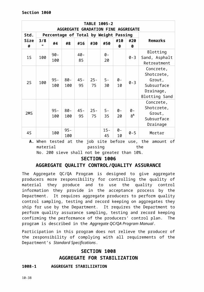
Section 1060
before use in the concrete. Build open stockpiles of fine aggregate at the batch plant on concrete surfaces. Do not add new material to the stockpile during the 24 hour period. When the aggregates have a low and uniform moisture content and the consistency of the concrete can be satisfactorily controlled without stockpiling the aggregates for 24 hours, the minimum stockpiling period may be reduced or waived entirely by the Engineer.
The Department’s list of approved sources of fine aggregate shows the target fineness modulus of each aggregate as established by the producer. Do not use fine aggregate with a fineness modulus that varies more than 0.2 from the target value until the concrete mix proportions are adjusted.
(B)Soundness
When subjected to 5 cycles of the soundness test, the weighted average loss shall not be more than 15%.
(C)Deleterious Substances
Determine the percentage of deleterious substances (clay lumps and friable particles) in accordance with AASHTO T 112. The amount of deleterious substances shall not exceed 2.0% by weight for natural sand or 1.0% by weight for manufactured sand.
(D)Organic Impurities
The color of each source of fine aggregate will be determined annually in accordance with AASHTO T 21. Should the fine aggregate show a darker color than samples previously approved from the same source, withhold its use until tests have been made to determine the quality of the sand.
(E)Mortar Strength
Mortar made with the fine aggregate shall have a compressive strength at the age of 3 and 7 days using Type III Portland cement, or 7 and 28 days using Type I or II Portland cement, of not less than 95% of that developed by a comparison mortar. Make the comparison mortar with the same cement, graded Ottawa sand with a fineness modulus of 2.40 ± 0.05, and the same water-cement ratio and consistency as the test mortar. Test the mortar strength in accordance with AASHTO T 106.
Fine aggregate that fails the mortar strength may be used with the approval of the Engineer, provided that when it is tested in concrete cylinders the compressive strength of the concrete at 14 days is equal to or greater than the strength of cylinders made with an identical mix using an acceptable sand.
(F)Gradation
Natural sand shall meet the gradation for standard size No. 2S fine aggregate. Manufactured sand shall meet the gradation for standard size No. 2MS fine aggregate.
(G)Blending Fine Aggregate
Blending fine aggregates to obtain the required gradation will be permitted if test results of each aggregate meet the durability requirements and test results of the combination indicate acceptable quality. Blend aggregates by weighing them separately at the time of batching or by other means acceptable to the Engineer.
When natural sand is blended with natural sand, the blend shall meet the gradation for No. 2S fine aggregate. When manufactured sand is blended with natural sand or with manufactured sand, the blend shall meet the gradation for No. 2MS fine aggregate and neither component shall exceed the gradation limits on the No. 200 sieve shown in Table 1005-2.
10-38

Section 1000
1014-2 COARSE AGGREGATE
(A)General
Use coarse aggregate from sources participating in the Department’s Aggregate QC/QA Program as described in Section 1006. A list of these sources in North Carolina and adjoining states is available from the Materials and Tests Unit in Raleigh.
Use coarse aggregate that consists of crushed stone, crushed or uncrushed gravel, crushed air-cooled blast furnace slag or other inert materials that have similar characteristics. Wash all coarse aggregate for Portland cement concrete to remove clay, loam, dust and similar adherent materials unless otherwise permitted by the Engineer in writing. Keep coarse aggregate free from dirt, wood, paper, burlap and all other foreign material.
To permit excess water to drain and the moisture content to become uniform, stockpile the aggregates either at the producer’s plant or at the batch plant site for at least 24 hours before use in the concrete. Build open stockpiles of coarse aggregate at the batch plant on concrete surfaces. Do not add new material to the stockpile during the 24 hour period. Where the aggregates have low and uniform moisture content and the consistency of the concrete can be satisfactorily controlled without stockpiling the aggregates for 24 hours, the minimum stockpiling period may be reduced or waived entirely by the Engineer.
Do not mix coarse aggregate from different sources or use it in alternate batches except where permitted by the Engineer in writing. Blending of coarse aggregates to obtain the required gradation will be permitted if the different sizes are from the same source. Blend coarse aggregates by weighing them separately at the time of batching or by other means acceptable to the Engineer.
(B)Soundness
When subjected to 5 cycles of the soundness test, the weighted average loss shall not exceed 15%. For concrete with a 28 day design compressive strength greater than 6,000 psi, the loss shall not exceed 8%.
(C)Deleterious Substances
Determine the percentage of deleterious substances (clay lumps and friable particles) in accordance with AASHTO T 112. The amount of deleterious substances shall not exceed 3.2% by weight.
(D)Resistance to Abrasion
The percentage of wear of crushed stone or gravel shall not exceed 55%. For concrete with a 28 day design strength greater than 6,000 psi, the wear shall not exceed 40%.
(E)Aggregate Sizes
(1) General
Use standard size No. 57, No. 67, or No. 78M coarse aggregate in Portland cement concrete unless otherwise indicated.
(2) Latex Modified Concrete
Use standard size No. 78M coarse aggregate in latex modified concrete.
(3) Prestressed and Precast Concrete
Use standard size No. 67 or No. 78M coarse aggregate in prestressed and precast concrete.
(4) Use of More Than One Size
10-39

Section 1060
All concrete used in a single component of any structure shall be made with the same size aggregate.
(5) Portland Cement Concrete Pavement
Use standard size No. 57, No. 57M, No. 67 or No. 78M coarse aggregate in concrete for Portland cement concrete pavement unless otherwise specified by the Engineer.
(6) Sand Lightweight Concrete
Use the following gradation for the lightweight coarse aggregate
TABLE 1014-1GRADATION FOR LIGHTWEIGHT COARSE AGGREGATE
Sieve Size Passing Square Opening Sieves(Percent by Weight)
1" 1003/4" 90 - 1003/8" 10 - 50
No. 4 0 - 15
(7) Drilled Pier Concrete
Use standard size No. 78M coarse aggregate in Drilled Pier concrete.
SECTION 1016SELECT MATERIALS
1016-1 DESCRIPTION
Select material is suitable material classified by gradation and performance characteristics as shown in this section. Use select material called for on the contract.
1016-2 USES
Select material may be specified for use in:
Subgrade Slope and shoulder embankmentBackfill in undercut Rock embankment in open waterCore material Material placement over fabricFoundation conditioning Pipe backfill
With written approval and without additional compensation, a higher class of material may be substituted than stated in the contract.
1016-3 CLASSIFICATIONS
CLASS I
Class I select material is silty or clayey soil material meeting AASHTO M 145 for soil classification A-4. Soil materials which meet AASHTO M 145 for soil classifications A-2, A-5, A-6 and A-7 are acceptable provided such materials do not have a LL greater than 50, nor a PI of less than 7 or greater than 20.
CLASS II
Type 1 Select Material
Type 1 select material is a fine aggregate material consisting of crushed stone screenings (washed or unwashed) meeting the gradation in Table 1016-1.
10-40

Section 1000
TABLE 1016-1 GRADATION FOR CLASS II, TYPE 1 SELECT MATERIAL
Sieve % Passing3/8 in 100
#4 80 - 100#10 65 - 95#40 25 - 55#200 0 - 20LL ≤ 30PI ≤ 6
Type 2 Select Material
Type 2 select material is a granular soil material meeting AASHTO M 145 for soil classifications A-2-4 with a maximum PI of 6 and A-4 soil containing 45% maximum passing a No. 200 sieve and a maximum PI of 6.
When a type is not specified, either type may be used, but no additional compensation will be made.
CLASS III
Type 1 Select Material
Type 1 select material is a natural or manufactured fine aggregate material meeting the gradation requirements of standard size 2S or 2MS in Table 1005-2 as described in Sections 1005 and 1006.
Type 2 Select Material
Type 2 select material is a granular soil material meeting AASHTO M 145 for soil classification A-1 or A-3.
When a type is not specified, either type may be used, but no additional compensation will be made.
CLASS IV
Select material is a coarse aggregate material meeting the gradation requirements of standard size ABC as described in Section 1010.
CLASS V
Select material is a coarse aggregate material meeting the gradation requirements of standard size 78M in Table 1005-1 as described in Section 1005 and 1006.
CLASS VI
Select material is a coarse aggregate material meeting the gradation requirements of standard size 57 in Table 1005-1 as described in Section 1005 and 1006.
Class VII
Select material is clean, unweathered durable, blasted rock material with the following gradation:
(A)At least 50% of the rock has a diameter of from 1.5 ft to 3 ft,
(B)40% of the rock ranges in size from 2" to 1.5 ft in diameter, and
(C)Not more than 10% of the rock is less than 2" in diameter. No rippable rock will be permitted.
10-41

Section 1060
SECTION 1018BORROW MATERIAL
1018-1 GENERAL
Borrow material is used for embankments, backfill or other intended uses. Material that contains roots, root mats, stumps or other unsatisfactory material will not be acceptable.
1018-2 APPROVAL OF BORROW SOURCE
The approval of borrow sources is subject to Section 230.
(A)Statewide Criteria for Acceptance of Borrow Material
See exceptions in Subarticle 1018-2(B).
Use only natural earth materials as borrow material. Any other materials are subject to rejection.
TABLE 1018-1PIEDMONT AND WESTERN AREA CRITERIA FOR ACCEPTANCE OF BORROW MATERIAL
Soil with PI of 25 or less Acceptable
Soil with PI of 26 through 35 Acceptable, but not to be used in top 2 ft of embankment or backfill
Soil with PI of more than 35 Not Acceptable
(B)Exceptions to Statewide Criteria for Acceptance of Borrow Material
(1) Soils in the Coastal Plain (area described below) will be accepted in accordance with the Table 1018-2.
TABLE 1018-2COASTAL AREA CRITERIA
FOR ACCEPTANCE OF BORROW MATERIALSoil with PI of 15 or less Acceptable
Soil with PI of 16 through 20 Acceptable, but not to be used in top 2 ft of embankment or backfill
Soil with PI of more than 20 Not Acceptable
Areas where Table 1018-2 is applicable are as follows:
Division 1 Entire Division except Northampton (West of I-95)Division 2 Entire DivisionDivision 3 Entire DivisionDivision 4 Edgecombe, Wayne, Johnston (East of US 301), Wilson (East of I-95),
Nash (East of I-95), Halifax (East of I-95)Division 6 Bladen, Columbus, Robeson, Cumberland, Harnett (South of NC 27)Division 8 Scotland, Hoke, Moore (Southeast of US 15-501, NC 73, NC 211),
Richmond (East of US 220 North and US 1 South)
Table 1018-2 shall be applicable to the flood plains of the Roanoke, Tar, Neuse, Cape Fear and Lumber Rivers and their tributaries that are outside the above described areas.
(2) Waste or by-products from industrial processes or mining operations are not acceptable except by specific written approval.
(3) When tested, soils having a pH of less than 5.5 or an organic content more than 4.0% may be rejected.
10-42

Section 1000
(4) When material is to be used for placing embankments or backfilling of undercut areas that are excessively wet, the material shall consist of Class II, III or IV select material.
SECTION 1019SHOULDER AND SLOPE MATERIAL
1019-1 GENERAL
Use shoulder and slope material to construct shoulders and plate slopes with materials capable of supporting vegetation. Material that contains roots, root mats, stumps or other unsatisfactory material will not be acceptable.
1019-2 SHOULDER AND SLOPE BORROW
Use borrow sources in accordance with Article 1018-2.
Use soil consisting of loose, friable, sandy material with a PI greater than 6 and less than 25 and a pH ranging from 5.5 to 6.8. Remove stones and other foreign material 2" or larger in diameter.
Use approved material obtained from unclassified excavation, fine grading operations or borrow sources as provided in Section 230.
1019-3 AGGREGATE SHOULDER BORROW
Use aggregate shoulder borrow (ASB) that meets the following gradation in Table 1019-1.
TABLE 1019-1GRADATION OF AGGREGATE SHOULDER BORROW
Sieve Percentage Passing1 1/2" 1001/2" 55-95#4 35-74
SECTION 1020ASPHALT MATERIALS
1020-1 DELIVERY AND ACCEPTANCE OF ASPHALT MATERIALS
Asphalt materials are accepted at the source of shipment subject to the conditions herein.
All asphalt transport tankers, including rail and truck tankers, shall have a sampling valve in accordance with Asphalt Institute Publication MS-18, ASTM D140 or a comparable device acceptable to the Engineer.
Each transport tanker delivering asphalt materials to the project or rail siding shall keep a running log showing the date, destination and type and grade of material hauled on each trip. Print, stamp, or write in ink information appearing in the log and have available for examination upon request.
Furnish with each shipment 2 copies of a delivery ticket. Ensure both copies accompany the shipment and are delivered to the Engineer or his representative at the destination. The delivery ticket shall contain the following information:
(A) Name of Producer/Supplier and location(B) A statement that the material has been tested and meets AASHTO specifications or is
being provided by an approved supplier under Approved Supplier Certification (ASC)(C)The grade of the material(D)If applicable, the rotational viscosity in Pascal-Seconds (Pa-S) at 135°C and 165°C
10-43

Section 1060
(E) If applicable, the recommended laboratory mixing and compaction temperature (°C for the PGAB)
(F)Delivery ticket number(G)Date and time loaded (mm/dd/yyyy AM:PM)(H)Date and time shipped (mm/dd/yyyy AM:PM)(I) State project or purchase order number(J) NCDOT assigned batch number(K)Destination(L) Name of consignee(M) Trailer or car number(N)Producer’s or Supplier’s storage tank and batch number(O)Quantity loaded in tons or gallons (kg/L) at 60°F(P)Loading temperature(Q)Net gallon at 60°F
When anti-strip additive is introduced into the asphalt binder, ensure the delivery ticket notes the brand, grade and percentage or quantity at which the additive was introduced.
The Contractor’s asphalt materials supplier shall furnish to the Materials and Tests Unit a typical viscosity-temperature chart at the beginning of each calendar year and a new chart whenever a change in production results in a shift of 5°F or more.
Furnish a statement of certification from the supplier and a separate statement of certification from the transporter. Sign each certification by an authorized representative of the supplier or transporter. Stamp, write or print these certifications on the delivery ticket, or attach to the delivery ticket.
Unless otherwise approved by the Engineer, the following form shall be used in the supplier’s certification:
This is to certify that this shipment of _____________ gallons/liters or tons/metric tons of ______________ grade asphalt including __________ gallons/liters of __________________ anti-strip meet all requirements of NC Department of Transportation Specifications.
Signed ________________________Authorized Representative of Supplier
When no anti-strip additive is included with the load, the supplier shall indicate zero (0) in the gallons field and “NA” in the anti-strip field on the above certification.
Unless otherwise approved by the Engineer, the following form shall be used in the transporter’s certification:
This is to certify that this transport tank was clean and free from contaminating materials when loaded. The material transported on the previous load in this tanker was __________________________________.
Signed ________________________Authorized Representative of Transporter
Failure to sign the certifications by either the supplier or transporter will be cause to withhold use of the material until a sample can be taken and tested, except where an alternative testing and invoicing procedure has been pre-approved by the Engineer.
The Engineer reserves the right to sample and test any shipment regardless of whether or not the above conditions have been met and to reject any material not meeting the Specifications.
1020-2 ASPHALT BINDER
10-44

Section 1000
Use performance graded asphalt binder meeting AASHTO M 320 Table 1. See Article 610-3 for the specified grades.
Submit a Quality Control Plan for asphalt binder production in conformance with AASHTO R 26 to the Materials and Tests Unit. The Department’s Performance Graded Asphalt Binder QC/QA Program shall be implemented in accordance with Article 1020-6.
Where modification of the asphalt binder is required to meet the specified grade, accomplish the modification using a styrene butadiene styrene (SBS), styrene butadiene rubber (SBR), styrene butadiene (SB) polymer or other modifiers approved by the Engineer to modify asphalt to meet the grade specified before delivery to the asphalt plant. Other polymers shall be pre-approved and listed by the Materials and Tests Unit. Air blown asphalt will not be permitted.
1020-3 ASPHALT EMULSION
Submit a QC Plan for asphalt emulsion. The Department’s Asphalt Emulsion QC/QA Program shall be implemented in accordance with Article 1020-6.
(A)Anionic
Use asphalt emulsion, except for Grade RS-1H, that meets AASHTO M 140. Use asphalt emulsion Grade RS-1H that meets AASHTO M 140 for Grade RS-1, except the penetration of residue shall be at least 50 and no more than 100.
Perform the testing of the asphalt in accordance with AASHTO T 59 except as follows:
(1) Use a hot plate instead of an oven to perform the residue by evaporation.
(2) The determination of coating test, oil distillate, pH, solubility of residue, ash and particle charge will be made when deemed necessary.
(3) Use Materials and Tests Method A-24 to determine the coating ability and water resistance using either crushed or uncrushed aggregate from a source selected by the Department.
(B)Cationic
Asphalt emulsion shall meet AASHTO M 208 except as follows:
(1) Asphalt emulsion Grade CRS-1H shall meet AASHTO M 208 for Grade CRS-1 except as follows:
(a) The residue after distillation shall be at least 55%.
(b) The penetration of residue shall be at least 50 and no more than 100.
(c) Viscosity, Saybolt Furol at 77°F shall be at least 20 and no more than 100.
(2) All polymer or latex modified cationic asphalt emulsion materials, CRS-2P and CRS-2L, are subject to the following requirements:
(a) The viscosity at 122°F shall be at least 100 seconds and no more than 400 seconds.
(b) The sieve shall be no more than 0.15%.
(c) The 24 hour storage stability shall not exceed 1%.
(d) The residue by evaporation (oven evaporation) shall be at least 65%.
(e) The elastic recovery (AASHTO T 301) at 50°F shall be at least 50%.
(f) The ring and ball softening point (AASHTO T 53) shall be at least 110°F.
10-45

Section 1060
(g) Polymer content may be analyzed, if deemed necessary.
(3) Perform the testing of the asphalt in accordance with AASHTO T 59 except as follows:
(a) Residue by evaporation will be performed using a hot plate instead of an oven with a maximum temperature of 400°F. Referee testing will be performed in accordance with AASHTO T 59.
(b) The determination of coating test, oil distillate, pH, solubility of residue, ash and particle charge will be made when deemed necessary by the Engineer.
(c) Materials and Tests Method A-24 is used to determine the coating ability and water resistance using either crushed or uncrushed aggregate from a source selected by the Department.
1020-4 POLYMER MODIFIED EMULSION MEMBRANE
Use polymer modified emulsion membrane consisting of styrene butadiene block copolymer modified asphalt emulsion to form a water impermeable seal and bond the new hot mix to the existing surface. Complete polymer modification of base asphalt before emulsification. Conform to Table 1020-1.
TABLE 1020-1EMULSION AND RESIDUE TESTING
Property Requirement Test MethodEMULSION: Min. Max.Viscosity @ 77°F, SFS 20 100 AASHTO T 59
Sieve Test, % 0.1 AASHTO T 5924-Hour Storage Stability, %A 1 AASHTO T 59
Residue from Distillation @ 400°F, %B 63 AASHTO T 59Oil portion from distillation ml of oil per 100 g emulsion 2.0
Demulsibility 60 AASHTO T 59RESIDUE:
Solubility in TCE, %C 97.5 AASHTO T 44Elastic Recovery, 50°F20 cm elongation %D 60 AASHTO T 301
Penetration @ 77°F, 100 g, 5 sec, dmm 60 150 AASHTO T 49A. After standing undisturbed for 24 hours, the surface shall show no white, milky colored
substance, but shall be a smooth homogeneous color throughout.B. AASHTO T 59 with modifications to include a 400°F ± 10°F maximum temperature to
be held for 15 minutes.C. ASTM D5546 may be substituted where polymers block the filter in Method D 2042.D. ASTM D6084 except that the elongation is 20 cm and the test temperature is 50°F.
1020-5 PRIME COAT MATERIALS
Supply prime coat materials from pre-approved sources in accordance with Materials and Tests Unit Method A and listed by the Materials and Tests Unit. Verification samples taken at the point of application (destination) are subject to the following conditions:
(A)All prime coat materials shall be delivered to the project ready for use.
(B)Sampling will be made at the point of application. The Department reserves the right to sample all materials used for prime coat applications, either at the destination or at the point of origin, and to withhold acceptance of material until analysis of such samples have been made. When a material meets specification requirements, but has a history of unsatisfactory service performance, its use for construction or maintenance purposes may
10-46
Section 1000
be restricted by the Department and such restriction will be noted on the list of approved products.
(C)Proposed materials for prime coat applications that are not listed as approved will be investigated upon the request of the supplier or Contractor. The maximum volatile organic compounds for the products (materials) on the approved list for prime coat applications shall not exceed 6.8 oz/gal of material or the current applicable regulatory limit. Submit a MSDS and a 2 quart sample from 3 different batches of the same material to the Materials and Tests Unit for evaluation.
(D)The sand penetration results for a material used as a prime coat are penetration depth of at least 12 mm and penetration time of not more than 90 seconds. Copies of the Sand Penetration Test Procedure are available upon request from the Materials and Tests Unit.
(E)Materials used as a prime coat shall have a minimum rating of fair on the No-Tracking Time Test. Copies of the No-Tracking Time Test Procedures are available upon request from the Materials and Tests Unit.
(F)Materials used as a prime coat shall have a minimum rating of fair on the coating ability and water resistance test in accordance with AASHTO T 59.
(G)For materials stored longer than one day at the destination point (Contractors’/Divisions’ tanks), submit to the Engineer a certified laboratory report on the performance of the material for storage stability test in accordance with AASHTO T 59.
(H)The diluted materials shall be tested for asphalt residue percent in accordance with AASHTO T 59, Section 55, and shall have a minimum asphalt residue percent of 15%.
1020-6 PERFORMANCE GRADED ASPHALT BINDER AND ASPHALT EMULSION QUALITY CONTROL/QUALITY ASSURANCE
The Performance Graded Asphalt Binder and Asphalt emulsion QC/QA Programs are designed to give asphalt binder and asphalt emulsion producers/suppliers (henceforth Producer designates Producer/Supplier) more responsibility for controlling the quality of material they produce and to use the quality control information they provide in the acceptance process by the Department. It requires asphalt binder and asphalt emulsion producers to perform quality control sampling, testing and record keeping on materials they ship for use by the Department. It documents that the Department will perform quality assurance sampling, testing and record keeping confirming the performance of the producers’ control plan. In addition, the Producer is required to participate in independent assurance comparative sample activities. The program is described in the Performance Graded Asphalt Binder and Asphalt Emulsion QC/QA Program Manuals. An electronic copy of the program manuals may be obtained by accessing the Materials and Tests website.
The types of samples and the lot sizes required by the Producers and the Department are described in detail in the Performance Graded Asphalt Binder and Asphalt Emulsion QC/QA Program Manuals.
Acceptance or rejection of material will be based on the total program. Therefore, a comparison of the quality control, quality assurance and other sample data may be used by the Department for acceptance or rejection of a lot of material.
Participation in this program does not relieve the producer of the responsibility of complying with all requirements of the Standard Specifications.
1020-7 WATERPROOFING AND DAMPPROOFING MATERIALS
(A)Asphalt Primer
Asphalt primer shall meet ASTM D41.
10-47

Section 1060
(B)Asphalt Binder
Asphalt Binder shall meet Article 1020-2, Grade PG 64-22.
(C)Tar
Tar shall meet ASTM D490.
(D)Fabric
Woven cotton fabric for waterproofing shall meet ASTM D173.
SECTION 1024MATERIALS FOR PORTLAND CEMENT CONCRETE
1024-1 PORTLAND CEMENT
Supply Portland cement that meets AASHTO M 85 for Type I, II or III except that the maximum fineness requirements of AASHTO M 85 do not apply to cement used in precast concrete products. Throughout these Specifications Types I and II cement are referred to as regular Portland cement and Type III as high early strength Portland cement.
Certain combinations of cement and aggregate exhibit an adverse alkali-silica reaction. The alkalinity of any cement, expressed as sodium-oxide equivalent, shall not exceed 1.0%. For mix designs that contain non-reactive aggregates and cement with an alkali content less than 0.6%, straight cement or a combination of cement and fly ash, cement and ground granulated blast furnace slag or cement and microsilica may be used. The pozzolan quantity shall not exceed the amount shown in Table 1024-1. For mixes that contain cement with an alkali content between 0.6% and 1.0% and for mixes that contain a reactive aggregate documented by the Department, use a pozzolan in the amount shown in Table 1024-1.
Obtain the list of reactive aggregates documented by the Department at the Materials and Tests Unit website.
TABLE 1024-1POZZOLANS FOR USE IN PORTLAND CEMENT CONCRETE
Pozzolan Rate
Class F Fly Ash 20% by weight of required cement content with 1.2 lb Class F fly ash per lb of cement replaced
Ground Granulated Blast Furnace Slag
35%-50% by weight of required cement content with 1.0 lb slag per lb of cement replaced
Microsilica 4%-8% by weight of required cement content with 1.0 lb microsilica per lb of cement replaced
Type IP or IS blended cement is allowed for the cement-and-fly-ash or cement-and-slag portion of the mix. Type IT may be allowed for the cement-and-pozzolan portion of the mix with the permission of the Engineer. Do not substitute fly ash or slag for a portion of Type IP, IS or IT cement or for Portland cement in high early strength concrete.
Use white cement that meets ASTM C150, except that the ferric oxide content is limited to 0.5%.
Use Type IP blended cement that meets AASHTO M 240, except that the pozzolanic content is limited to between 17 and 23% by weight and the constituents shall be interground.
Use Type IS blended cement that meets AASHTO M 240 except that the slag content is limited to between 35% and 50% by weight and the constituents are interground.
Use Type IT blended cement that meets AASHTO M 240. The Engineer will evaluate the blend of constituents for acceptance in Department work.
10-48

Section 1000
Do not use air-entraining Portland cement. Do not mix different types of cement, different brands of cement, or the same brand from different mills nor use them alternately except when authorized in writing by the Engineer.
10-49

Section 1060
Protect cement from contamination or damage during handling and storage. Do not use cement that is damaged, partially set, lumpy or caked.
All cement is sampled and tested by the Department as it arrives on the project or at the precasting plant at such frequency as established by the Department.
1024-2 AGGREGATE
Provide aggregate that meets Section 1014.
1024-3 ADMIXTURES
(A)Basis of Acceptance
Admixtures from an approved source are accepted without prior testing. Do not use admixtures that are not from an approved source until the admixture is approved by the Department.
(B)Approved Sources
An approved source is considered to be any manufacturer of admixtures who complies with this subarticle.
The manufacturer shall submit to the Materials and Tests Unit certified reports of tests that show that the admixture meets the applicable Specifications. Perform tests in a laboratory certified by the Cement and Concrete Reference Laboratory of the National Bureau of Standards.
Admixtures that contain chloride other than calcium chloride as provided herein are not permitted. The manufacturer is required to state in writing that no chloride was added during the manufacture of the admixture.
After an admixture is accepted, the manufacturer is required to submit to the Materials and Tests Unit on or before February 1 of each year a notarized certification that shows that the material is of the same composition as originally accepted and has not been changed or altered. If an admixture is changed or altered, approval of the source in accordance with the above requirements is necessary before using the admixture.
The Engineer has the option to make any or all tests deemed desirable to verify the manufacturer’s certification. Failure of the admixture in such tests is cause for discontinuation of its use. Failure of an admixture to perform satisfactorily under job conditions is cause for rejection of the source.
The Engineer maintains a list of approved sources on file.
(C)Air Entraining Agent
Provide air entraining agents that meet AASHTO M 154.
(D)Chemical Admixtures
(1) Set Retarding Admixtures
Use set retarding admixtures that meet AASHTO M 194 for Type D, water reducing and retarding admixtures.
(2) Water Reducing Admixtures
Use water reducing admixtures that meet AASHTO M 194 for Type A admixtures.
(3) Calcium Chloride
10-50

Section 1000
Provide calcium chloride that meets AASHTO M 144 for Type 2, concentrated flake, pellet or other granular calcium chloride. The Engineer may waive the gradation requirement.
(4) High-Range Water Reducing Admixtures
Use high-range water reducing admixtures that meet AASHTO M 194 for Type F or Type G.
(5) Calcium Nitrite Corrosion Inhibitor
Use an approved calcium nitrite corrosion inhibitor that contains 30% solids.
(E)Other Admixtures
Admixtures not otherwise classified will be reviewed on a case-by-case basis by the Materials and Tests Unit.
1024-4 WATER
Ensure that water used to condition, wash, or as an integral part of materials is clear and free from injurious amounts of oil, acid, alkali, organic matter, or other deleterious substance. It shall not be salty or brackish. Water used in the production of concrete or grout shall be from wells or public water systems which are suitable for drinking and must meet the criteria listed in Table 1024-2.
Test all water from wells and public water supplies from all out of state locations and in the following counties: Beaufort, Bertie, Brunswick, Camden, Carteret, Chowan, Craven, Currituck, Dare, Gates, Hyde, New Hanover, Onslow, Pamlico, Pasquotank, Pender, Perquimans, Tyrell and Washington unless the Engineer waives the testing requirements. Water from a municipal water supply in all other NC counties may be accepted by the Engineer without testing.
TABLE 1024-2PHYSICAL PROPERTIES OF WATER
Property Requirement Test MethodCompressive Strength, minimum percent of control at 3 and 7 days 90% NCDOT Modified /
AASHTO T 106
Time of set, deviation from control
From 1:00 hr. earlier
to 1:30 hr. later
NCDOT Modified / AASHTO T 131
pH 4.5 to 8.5 NCDOT Modified / AASHTO T 26
Chloride Ion Content, Max. 250 ppm ASTM D512
Total Solids Content (Residue), Max. 1,000 ppm
NCDOT Modified / Standard Methods for Examination of
Water and Wastewater
Resistivity, Min. 0.500 kohm-cm NCDOT Modified / ASTM D1125
Sulfate as SO4,, Max. 1,500 ppm NCDOT Modified / ASTM D516
Presence of Sugar None NCDOT Procedure
Dissolved Organic Matter None NCDOT Modified / AASHTO T 26
1024-5 FLY ASH
Provide fly ash that meets ASTM C618 for Class F or Class C, except ensure that the loss on ignition does not exceed 4%. Table 1A of ASTM C618 applies to Class F fly ash. Use fly
10-51

Section 1060
ash that meets the optional physical requirements for uniformity shown in Table 2A of ASTM C618.
Do not use Class C fly ash in Portland cement concrete if the alkali content of the cement exceeds 0.4%.
All fly ash is sampled and tested by the Department as it arrives on the project at such frequency as established by the Department.
1024-6 GROUND GRANULATED BLAST FURNACE SLAG
Use blast furnace slag that meets AASHTO M 302, Grade 100. All slag is sampled and tested by the Department as it arrives on the project at such frequency as established by the Department.
1024-7 SILICA FUME
Provide silica fume (microsilica) that meets Tables 1, 2 and 3 of ASTM C1240 All silica fume is sampled and tested by the Department as it arrives on the project at such frequency as established by the Department.
SECTION 1026CURING AGENTS FOR CONCRETE
1026-1 GENERAL
All curing agents shall be free from impurities that may be detrimental to the concrete. Do not use curing agent until the applicable tests have been performed and the Engineer has approved the curing agent.
1026-2 LIQUID MEMBRANE CURING COMPOUNDS
(A)General
Liquid membrane curing compounds shall meet AASHTO M 148, except that when tested in the water retention test described in AASHTO T 155 the curing compound shall restrict the loss of water in the test specimen at the time of application of the compound to not more than 0.007 oz/sq.in.
The curing compound shall be Type 2, white pigmented, except where clear type is required for a particular application, the curing compound shall be Type 1D, clear or translucent with fugitive dye.
Deliver curing compound in the manufacturer’s original clean, sealed containers. Legibly mark each container with the name of the manufacturer, the name of the compound, the type of compound, the manufacturer’s batch number, the date of manufacture and the manufacturer’s recommended shelf life.
Do not use curing compound that has been in storage for more than one year from the date of manufacture or more than the manufacturer’s recommended shelf life, whichever is less.
(B)Test Procedures
Curing compound will be tested in accordance with AASHTO M 148, except the size of molds for making test specimens will be approximately 5.5" in diameter by approximately 1" deep, or any other size selected by the Engineer.
1026-3 POLYETHYLENE FILM
Polyethylene film shall meet AASHTO M 171 for white opaque polyethylene film, except that when tested for moisture retention efficiency the loss shall not be more than 0.007 oz./sq.in of surface area.10-52

Section 1000
1026-4 WATER
All water used for curing concrete shall meet Article 1024-4 and Table 1024-2. Water from wells, streams, ponds or public water systems may be used.
1026-5 BURLAP
Burlap shall meet AASHTO M 182. Any class of burlap will be acceptable.
Use new burlap or burlap that has been used for no purpose other than curing concrete. New burlap shall be free from starch, filler or other substances added during manufacture, or shall be washed to remove such substances before use.
SECTION 1028JOINT MATERIALS
1028-1 JOINT FILLER
Provide a nonbituminous type joint filler that meets AASHTO M 153 for Types I, II or III, or a bituminous type that meets AASHTO M 213. Furnish a Type 3 material certification in accordance with Article 106-3 with each lot of the joint material supplied to each project.
1028-2 HOT APPLIED JOINT SEALER
Provide a hot applied joint sealer that conforms to ASTM D6690 and has been evaluated by NTPEP. Furnish a Type 3 material certification in accordance with Article 106-3 for each lot of the joint sealer supplied to each project.
1028-3 LOW MODULUS SILICONE SEALANT
Provide a cold applied, single component, chemically curing low modulus silicone sealant from the Department’s approved list on the website and evaluated by NTPEP. Acid cure sealants are not acceptable for use on Portland cement concrete. Bond breakers shall meet Article 1028-4.
(A)Silicone Sealant Types
(1) Type NS
A non-sag silicone for use in sealing horizontal and vertical joints in Portland cement concrete pavements and bridges. Tooling is required.
(2) Type SL
A self-leveling silicone used to seal horizontal joints in Portland cement concrete pavements and bridges. Tooling is not normally required.
(B)Requirements
TABLE 1028-1PHYSICAL PROPERTIES OF SEALANT
Property Requirement Test Method
PeelMinimum of 20 lb/in of
width with at least 75% cohesive failure
ASTM D903 bonded on concrete block
Movement Capability and Adhesion
No adhesive or cohesive failure after 10 cyclesof test movements of
+100% (extension) and–50% (compression)
ASTM C719
10-53
Section 1060
Silicone sealant shall meet the Table 1028-1, ASTM D5893 and shall have been evaluated by NTPEP.
Furnish a Type 3 material certification in accordance with Article 106-3 for each lot of joint sealer material supplied to each project. Deliver each lot of sealant in containers plainly marked with the manufacturer’s name or trademark, lot number and date of manufacture.
1028-4 BOND BREAKER
Install silicone sealant over a bond breaker to prevent the sealant from bonding to the bottom of the joint. Use bond breakers that do not stain or adhere to the sealant and are chemically inert and resistant to oils. Furnish a Type 3 material certification in accordance with Article 106-3 for each lot of bond breaker material supplied to each project.
(A)Type L
Type L backer rod is a closed-cell expanded polyethylene foam backer rod. Use this backer rod in roadway and bridge joints and with Type NS silicone only. Use Type L backer rod that complies with Table 1028-2.
(B)Type M
Type M backer rod is a closed-cell polyolefin foam backer rod which has a closed-cell skin over an open cell core. Use this backer rod in roadway and bridge joints with both silicone sealant types. Use Type M backer rod that complies with Table 1028-2.
TABLE 1028-2PHYSICAL PROPERTIES OF TYPE L AND TYPE M BACKER ROD
Property Requirement Test MethodMin. Density 2.0 lb/cf ASTM D1622
Min. Tensile Strength 25 psi ASTM D1623Max. Water Absorbtion 0.5% by volume ASTM C509
(C)Type N
Provide bond breaking tape made from extruded polyethylene that has a pressure sensitive adhesive on one side. Bond breaking tape may be used with both types of silicone but is suitable for bridge joints only. Bond breaking tapes shall be at least 0.005" in thickness.
SECTION 1032CULVERT PIPE
1032-1 CORRUGATED METAL CULVERT PIPE
Use corrugated metal culvert pipe from sources on the Department’s approved list and that participate in the Department’s Brand Registration program for metal culvert pipe available from the website or the Materials and Tests Unit’s Central Laboratory. The Department will remove a manufacturer of metal culvert pipe from this program if the monitoring efforts indicated that non-specification material is being provided or test procedures are not being followed.
The following types of steel and aluminum alloy pipe and all associated accessories may be accepted under this program.
(A)Coated corrugated metal culvert pipe and pipe arches,
(B)Coated corrugated metal end sections, coupling band and other accessories,
(C)Corrugated aluminum alloy structural plate pipe and pipe arches,
10-54

Section 1000
(D)Corrugated aluminum alloy end sections, coupling band and other accessories, and
(E)Welded steel pipe.
1032-2 CORRUGATED ALUMINUM ALLOY CULVERT PIPE
(A)Corrugated Aluminum Alloy Culvert Pipe
Corrugated aluminum alloy culvert pipe shall meet AASHTO M 196, except that Type IA pipe will not be permitted.
When elongated pipe is called for by the contract, use pipe that is shop formed to provide for a 5% vertical elongation.
Coupling bands with projections may be used for circumferential pipe, helical pipe, or a combination of both.
(B)Corrugated Aluminum Alloy Pipe Tees and Elbows
Corrugated aluminum alloy pipe tees and elbows shall meet all applicable requirements of AASHTO M 196.
(C)Acceptance
Acceptance of corrugated aluminum alloy culvert pipe and its accessories will be based on, but not limited to, visual inspections, classification requirements and check samples taken from material delivered to the project and conformance to the annual Brand Registration.
Culvert pipe materials not meeting the above requirements will be rejected, unless written approval is obtained from the State Materials Engineer.
1032-3 CORRUGATED STEEL CULVERT PIPE
(A)Corrugated Steel Culvert Pipe and Pipe Arch
Corrugated steel culvert pipe and pipe arch shall meet AASHTO M 36 with the following exceptions:
(1) Coupling Bands
(a) Use corrugated coupling bands except as otherwise provided below.
(b) A hugger type corrugated band having one annular corrugation at each outside edge of the band will be acceptable.
(c) Coupling bands with projections may be used where it is necessary to join new pipe to existing pipe having helical corrugations at the joint locations. Use an approved sealer with this type of coupling band.
(d) Fasten coupling bands on the ends with at least two 1/2" bolts.
(e) Annular corrugated bands shall have a minimum width of 10 1/2" where 2 2/3" x 1/2" corrugations are used.
(2) Corrugations
Where 1/4" deep corrugations are permitted by AASHTO M 36, the maximum pitch of the corrugations shall be 1 7/8".
Where 3" x 1" corrugations are required, the Contractor will be permitted to use 5" x 1" corrugations.
Pipe with helical corrugations shall have rerolled ends with at least 2 annual corrugations at each end.
10-55

Section 1060
(3) Elongated Pipe
When elongated pipe is called for by the contract, use pipe that is shop formed to provide for a 5% vertical elongation.
(4) Lifting Straps
The pipe may be furnished either with or without lifting straps for handling. Attach the lifting straps by bolting or by welding. Bolt holes for attaching the straps shall be a smooth hole that is either punched or drilled. No burning of holes will be permitted. Design the lifting straps so the holes can be plugged to prevent infiltration of backfill material.
Design the placement of lifting straps to ensure the pipe is equally supported along its axis.
(5) Coating Repair
Repair shall be in accordance with Section 1076-7.
(6) Type IA Pipe
Type IA pipe will not be permitted.
(7) Aluminized Pipe
Aluminized pipe shall meet all requirements herein except that the pipe and coupling bands shall be fabricated from aluminum coated steel sheet meeting AASHTO M 274.
(8) Marking Requirements
Pipe sections and special attachments for pipe 60" or larger diameter pipe shall be alphanumerically match-marked at the plant site before shipping. There may be additional markings as required by the Department’s Brand Certification Program.
(B)Prefabricated Corrugated Steel Pipe End Sections
Corrugated steel end sections shall be in accordance with the details shown in the plans and Subarticle 1032-3(A). Repair end sections on which the spelter coating has been bruised or broken either in the shop or in shipping in accordance with AASHTO M 36.
(C)Corrugated Steel Pipe Tees and Elbows
Corrugated steel tees and elbows shall be in accordance with Subarticle 1032-3(A).
(D)Corrugated Steel Eccentric Reducers
Corrugated steel eccentric reducers shall be in accordance with Subarticle 1032-3(A) and the additional requirements shown below.
Construct the eccentric reducer so the invert or flow line from the large pipe through the reducer and into the small pipe is a continuous straight line.
Make the reducer from the same thickness corrugated metals as the large diameter pipe. The reducing section may be riveted or welded.
(E)Acceptance
Acceptance of corrugated steel culvert pipe and its accessories will be based on, but not limited to, visual inspections, classification requirements and check samples taken from material delivered to the project and conformance to the annual Brand Registration.
Culvert pipe materials not meeting the above requirements will be rejected, unless written approval is obtained from the State Materials Engineer.
10-56

Section 1000
The reducing section shall reduce in diameter no more than 3" in 24" of length. Rivet or weld a 24" long constant diameter stub to each end of the reducing section to form the complete reducer.
Have the completed reducer show careful, finished workmanship in all particulars. Repair reducers on which the spelter coating has been bruised or broken either in the shop or in shipping in accordance with AASHTO M 36. Reducers that show defective workmanship will be rejected. The following defects are evidence of poor workmanship, and the presence of any of them in any individual reducer will constitute sufficient cause for rejection:
(1) Not meeting required dimensions,(2) Not of the specified shape,(3) Uneven laps,(4) Ragged or diagonal sheared edges,(5) Loose, unevenly lined or spaced rivets,(6) Poorly formed rivet heads,(7) Lack of rigidity,(8) Dents or bends in the metal itself,(9) Uneven welds, or(10) Gaps in welds.
1032-4 COATED, PAVED AND LINED CORRUGATED STEEL CULVERT PIPE
(A)Coatings for Steel Culvert Pipe or Pipe Arch
The below coating requirements apply for steel culvert pipe, pipe arch, end sections, tees, elbows and eccentric reducers.
(1) Steel Culvert pipe shall have an aluminized coating, meeting the requirement of AASHTO M 274.
(2) When shown in the plans or as approved by the Engineer, a polymeric coating meeting AASHTO M 246 for Type B coating may be substituted for aluminized coating.
(B)Acceptance
Acceptance of coated steel culvert pipe and its accessories will be based on, but not limited to, visual inspections, classification requirements and check samples taken from material delivered to the project and conformance to the annual Brand Registration.
1032-5 WELDED STEEL PIPE FOR DRAINAGE
Welded steel pipe shall meet ASTM A139 for the grade of pipe called for in the plans.
Acceptance of welded steel culvert pipe and its accessories will be based on, but not limited to, visual inspections, classification requirements and check samples taken from material delivered to the project and conformance to the Department’s welded steel pipe program.
Culvert pipe materials not meeting the above requirements will be rejected, unless written approval is obtained from the State Materials Engineer.
1032-6 CONCRETE CULVERT PIPE
(A)General
Use concrete pipe from sources participating in the Department’s Concrete Pipe QC/QA Program. A list of participating sources is available from the Materials and Tests Unit’s Central Laboratory. The Department will remove a manufacturer of concrete pipe from this program if the monitoring efforts indicated that non-specification material is being provided or testing procedures are not being followed.
10-57

Section 1060
(B)Reinforced Concrete Culvert Pipe
Reinforced concrete culvert pipe shall meet AASHTO M 170 for the class of pipe called for in the plans except as follows:
(1) The permissible wall thickness outside of the joint configuration shall not be more than that shown in the design by more than 5% or 3/16", whichever is greater.
(2) The maximum weighted average loss for both fine and coarse aggregates shall be 15% when subjected to 5 cycles of the soundness test.
(3) The maximum percentage of wear for coarse aggregates is 55%.
The design wall thickness shall be either the wall thickness shown in AASHTO M 170 for the applicable class and wall or the wall thickness shown in a modified design that has been approved by the Engineer. A wall thickness greater than permitted by the above tolerance will be cause for rejection of the pipe. The circumferential steel in single cage pipe shall not be more than 3" from either end of the pipe section excluding the tongue and groove. On double cage pipe, extend one cage into the tongue or groove. Place the other cage so a circumferential wire shall be not less than 2" from the other end of the barrel of the pipe.
(C)Precast Concrete Pipe End Sections
Precast concrete pipe end sections shall meet AASHTO M 170 and Section 1077 except those requirements pertaining to design.
Design concrete pipe end sections in accordance with the plans or with plans prepared by the manufacturer which have been approved by the Engineer. Reinforce all concrete pipe end sections. Use air entrained concrete in pipe end sections with a strength of 3,500 psi when tested in accordance with AASHTO T 22.
(D)Concrete Pipe Tees and Elbows
Concrete pipe tees and elbows shall meet AASHTO M 170 for the class of pipe tee or elbow called for in the plans.
(E)Marking
(1) Clearly etchmark the following information on the outside of each section of pipe, pipe end section, tee and elbow:
(a) Pipe class and type of wall if reinforced,
(b) The date of manufacture, and
(c) Name or trademark of the manufacturer.
(2) Clearly stamp, stencil, sticker or paint the following information on each section of pipe, pipe end section, tee and elbow:
(a) The State assigned plant number,
(b) The inside diameter of the pipe product, and
(c) The year of manufacture. This marking shall be in the following format: State plant number - diameter - year (CP99-24-06).
When concrete pipe, pipe end sections, tees and elbows have been inspected and accepted they will be stamped with the Department seal of approval. Do not use pipe sections, pipe end sections, tees, or elbows which do not have this seal of approval. Failure of as much as 20% of any lot of pipe due to cracks, fractures, variation in alignment or other manufacturing defects will be cause for the rejection of the entire lot. The lots shall be as designated by the manufacturer before inspection.
10-58

Section 1000
Individual lengths of pipe within the lot which were not specifically rejected but which are considered acceptable by the manufacturer may be removed from the rejected lot and resubmitted for inspection as a separate lot.
(F) Joint Materials
Cement shall meet Article 1024-1. Sand shall meet Article 1014-1 for fine aggregate or Article 1040-7 for mortar sand. Hydrated lime shall meet Article 1040-6.
Flexible plastic joint material shall meet AASHTO M 198 for Type B flexible plastic gaskets, except as follows:
(1) The flash point, Cleveland Open Cup (C.O.C.) shall be at least 325°F.
(2) The fire point, C.O.C. shall be at least 350°F.
1032-7 CORRUGATED POLYETHYLENE (HDPE) CULVERT PIPE
(A)General
Use corrugated polyethylene pipe from sources participating in the Department’s HDPE Pipe QC/QA Program. A list of participating sources is available from the Materials and Tests Unit. The Department will remove a manufacturer of polyethylene pipe from this program if the monitoring efforts indicated that non-specification material is being provided or test procedures are not being followed.
Use corrugated polyethylene culvert pipe that meets AASHTO M 294 for Type S or Type D and has been evaluated by NTPEP.
(B)End Treatments, Pipe Tees and Elbows
End treatments, pipe tees and elbows shall meet AASHTO M 294, Section 7.8.
(C)Marking
Clearly mark each section of pipe, end section, tee and elbow and other accessories according to the Department’s HDPE Pipe QC/QA Program:
(1) AASHTO Designation
(2) The date of manufacture
(3) Name or trademark of the manufacturer
When polyethylene pipe, end sections, tees and elbows have been inspected and accepted they will be stamped with the Department seal of approval. Do not use pipe sections, flared end sections, tees or elbows which do not have this seal of approval.
1032-8 PVC PROFILE WALL DRAIN PIPE
PVC pipe shall conform to AASHTO M 304. When rubber gaskets are to be installed in the pipe joint, the gasket shall be the sole element relied on to maintain a tight joint. Watertight joints shall be watertight in accordance with AASHTO M 304, unless a higher pressure rating is specified in the plans.
SECTION 1034SANITARY SEWER PIPE AND FITTINGS
1034-1 CLAY PIPE
Use extra strength vitrified clay sewer pipe conforming to ASTM C700. Manufacture all joints and seals in accordance with ASTM C425.
10-59

Section 1060
1034-2 PLASTIC PIPE
(A)PVC Gravity Flow Sewer Pipe
Use PVC pipe that conforms to ASTM D3034 with a minimum SDR of 35. Use pipe with push-on type joints having bells made as an integral part of the pipe conforming to ASTM D3212.
(B)PVC Force Main Sewer Pipe
(1) Pressure Rated Pipe
Use PVC pipe conforming to ASTM D2241 or to ANSI/AWWA C905 with a minimum SDR of 21 and minimum pressure rating of 200 psi. Use pipe with push-on type joints having bells made as an integral part of the pipe conforming to ASTM D3139 or pipe with butt fused joints made from ASTM D1784 Class 12454B plastic formulated for fusing.
Use PVCO pipe conforming to ASTM F1483 or to ANSI/AWWA C909 for molecularly oriented pipe with a minimum pressure rating of 200 psi. Use pipe with push-on type joints having bells made as an integral part of the pipe conforming to ASTM D3139.
(2) Pressure Class Pipe
Use PVC pipe conforming to ANSI/AWWA C900 with a minimum DR of 18 and a minimum pressure class of 235 psi. Use pipe with push-on type joints having bells made as an integral part of the pipe conforming to ASTM D3139 or pipe with butt fused joints made from ASTM D1784 Class 12454B plastic formulated for fusing.
(C)Polyethylene (PE) Pipe Force Main Sewer Pipe
Use PE pipe and tubing that conforms to AWWA C901 or AWWA C906 with a minimum pressure class of 200 psi.
1034-3 CONCRETE SEWER PIPE
Use reinforced concrete sewer pipe conforming to ASTM C76 or AASHTO M 170 with a Class III minimum rating. Use pipe with gasket joints conforming to ASTM C443 or AASHTO M 198 Type A or B.
1034-4 DUCTILE IRON PIPE
(A)Gravity Flow Sewer Pipe
Use ductile iron pipe that conforms to ASTM A746 or ANSI/AWWA C151/A21.51.
Use ductile iron pipe fittings and specials conforming to ANSI/AWWA C110/A21.10 for standard size fittings or ANSI/AWWA C153/A21.53 for compact fittings.
Use pipe and fittings with push-on joints conforming to ANSI/AWWA C111/A21.11.
(B)Force Main Sewer Pipe
Use ductile iron pipe that conforms to ANSI/AWWA C151/A21.51.
Use ductile iron pipe fittings and specials conforming to ANSI/AWWA C110/A21.10 for standard size fittings or ANSI/AWWA C153/A21.53 for compact fittings. Manufacture fittings with a cement mortar lining and a seal coat in accordance with ANSI/AWWA C104/A21.4.
Use pipe and fittings with either mechanical joints or push-on joints conforming to ANSI/AWWA C111/A21.11. When required or necessary, use approved type joint
10-60

Section 1000
restraint devices with a minimum working pressure rating of 200 psi and a factor of safety of 2.
SECTION 1036WATER PIPE AND FITTINGS
1036-1 GENERAL
All materials when used to convey potable drinking water shall meet the National Sanitation Foundation Standard No. 61.
1036-2 COPPER PIPE
For indoor plumbing use copper pipe and sweated fittings conforming to ASTM B88 for the type and temper called for in the plans and Specifications. Cast fittings for copper pipe shall meet ASTM B61 or ASTM B62.
For buried service, use copper water pipe and tube conforming to ASTM B88 soft annealed Type K. Use flared or compression type fittings conforming to ANSI/AWWA C800 and local plumbing codes to connect pipe and tube.
1036-3 PLASTIC PIPE
(A)PVC Pipe
(1) Pressure Rated Pipe
Use PVC pipe conforming to ASTM D2241 or to ANSI/AWWA C905 with a minimum SDR of 21 and minimum pressure rating of 200 psi. Use pipe with push-on type joints having bells made as an integral part of the pipe conforming to ASTM D3139 or pipe with butt fused joints made from ASTM D1784 Class 12454B plastic formulated for fusing.
Use PVCO pipe conforming to ASTM F1483 or to ANSI/AWWA C909 for molecularly oriented pipe with a minimum pressure rating of 200 psi. Use pipe with push-on type joints having bells made as an integral part of the pipe conforming to ASTM D3139.
(2) Pressure Class Pipe
Use PVC pipe conforming to ANSI/AWWA C900 with a minimum DR of 18 and a minimum pressure class of 235 psi. Use pipe with push-on type joints having bells made as an integral part of the pipe conforming to ASTM D3139 or pipe with butt-fused joints made from ASTM D1784 Class 12454B plastic formulated for fusing.
(B)Polyethylene (PE) Pipe
Use PE water pipe and tubing that conforms to AWWA C901 or AWWA C906 with a minimum pressure class of 200 psi.
1036-4 STEEL PIPE
(A)Water Pipe
Use galvanized steel pipe meeting ASTM A53 for standard weight. Fittings for steel water pipe shall meet ASTM A126 for Class B iron or of ASTM A197. Galvanize all fittings in accordance with ASTM A153.
(B)Encasement Pipe
Use steel pipe meeting an ASTM specification with the minimum yield strength of 35,000 psi. Use pipe that is circular in shape and straight in length.
10-61

Section 1060
1036-5 DUCTILE IRON PIPE AND FITTINGS
Use ductile iron pipe that conforms to ANSI/AWWA C151/A21.51.
Use ductile iron pipe fittings and specials conforming to ANSI/AWWA C110/A21.10 for standard size fittings or ANSI/AWWA C153/A21.53 for compact fittings. Manufacture fittings with a cement mortar lining and a seal coat in accordance with ANSI/AWWA C104/A21.4.
Use either mechanical joints or push-on joints conforming to ANSI/AWWA C111/A21.11. When required or necessary, use approved type joint restraint devices with a minimum working pressure rating of 200 psi and a factor of safety of 2.
1036-6 FIRE HYDRANTS
Use dry barrel type fire hydrants conforming to ANSI/AWWA C502 with a minimum 4 1/2" diameter valve opening with a 6" mechanical joint inlet connection, with two 2 1/2" hose connections and with one 4 1/2" pumper connection. Outlets shall have national standard fire hose coupling threads. Use fire hydrants with a minimum bury length of 36". Securely chain nipple caps to the barrel. Paint hydrants with one coat of primer paint and 2 coats of an approved paint of the owner’s standard color. Apply the final coat after hydrant installation.
1036-7 WATER VALVES
(A)Gate Valves
Use iron body gate valves which conform to ANSI/AWWA C500 for bronze mounted, double disc, parallel seat type valves or to ANSI/AWWA C509 for resilient seat-type valves or to ANSI/AWWA C515 for reduced-wall, resilient seat gate valves. For buried service use gate valves with non-rising stems, 2" square operating nuts, O-ring seals and which open by turning counter clockwise. Gate valves shall have mechanical joint ends conforming to ANSI/AWWA C111/A21.11. Gate valves shall have a design working water pressure of 200 psi.
(B)Bronze Gate Valves
Use bronze gate valves conforming to ASTM B62 with tee head operating nuts and solid wedges. Use valves with a design working pressure of 200 psi.
(C)Tapping Valves
Use tapping valves conforming to Subarticle 1036-7(A) with appropriately sized openings, with flanged by mechanical joint ends and pressure rated at 200 psi.
1036-8 SLEEVES, COUPLINGS AND MISCELLANEOUS
(A)Tapping Sleeves
Use cast iron, ductile iron or Type 304 stainless steel tapping sleeves pressure rated at 200 psi. Use either the split sleeve type with mechanical joint ends or the full circle type with double seals. Manufacture the outlet flange to mate with the tapping valve flange.
(B)Transition Sleeves and Couplings
Use sleeve type couplings for transitioning between plain ends of different pipe types. Manufacture couplings in conformance with ANSI/AWWA C219 for a rated working pressure of 200 psi. Coat the coupling at the factory with an epoxy in conformance with ANSI/AWWA C210 or ANSI/AWWA C213.
1036-9 SERVICE LINE VALVES AND FITTINGS
10-62

Section 1000
Use corporation stops and curb stops of all bronze material and high-pressure construction conforming to ANSI/AWWA C800.
Use tapping saddles of high-pressure construction, shaped to conform to the pipe and in conformance with ANSI/AWWA C800.
Use high-pressure fittings manufactured in conformance with ANSI/AWWA C800.
SECTION 1040MASONRY
1040-1 BRICK
Use clay or shale brick that meets ASTM C62 for Grade SW, except as otherwise provided herein.
Use brick of uniform standard commercial size, with straight and parallel edges and square corners that are burned hard and entirely true, free from injurious cracks and flaws, tough, strong and have a clear ring when struck together. The sides, ends and faces of all brick shall be plane surfaces at right angles and parallel to each other.
Brick of the same manufacturer shall not vary more than ± 1/16" in thickness, ± 1/8" in width and ± 1/4" in length.
Concrete brick may be used instead of clay or shale brick when designated in the plans or in the specifications. Concrete brick shall meet ASTM C55 for Grade S-II except that the absorption of brick used in minor drainage structures shall not exceed 10 lb/cf.
1040-2 CONCRETE BUILDING BLOCK
Use concrete building block from sources that participate in the Department’s Solid Concrete Masonry Brick/Unit QC/QA Program. A list of these sources in North Carolina and adjoining states is available from the Materials and Tests Unit in Raleigh.
Use concrete building block that meets ASTM C90. Block shall be pink in color and substantially free from chips and cracks.
Use solid concrete block instead of clay brick for minor drainage structures that meet ASTM C139 except that the nominal dimensions shall be 4" x 8" x 16".
Concrete block for block manholes shall meet ASTM C139.
1040-3 CONCRETE PAVING BLOCK
Use concrete paving block from sources that participate in the Department’s Solid Concrete Masonry Brick/Unit QC/QA Program. A list of these sources in North Carolina and adjoining states is available from the Materials and Tests Unit in Raleigh.
Use concrete paving block that meet ASTM C139, except that the nominal dimensions shall be 4" x 8" x 16". The block shall have a uniform surface color and texture.
1040-4 SEGMENTAL RETAINING WALL UNITS
Use segmental retaining wall (SRW) units from sources that participate in the Department’s Solid Concrete Masonry Segmental Retaining Wall Units QC/QA Program. A list of these sources in North Carolina and adjoining states is available from the Materials and Tests Unit in Raleigh.
Use freeze-thaw durable SRW units when noted in the plans. Unless required otherwise in the contract, provide SRW units with a vertical straight face and a concrete gray color with no tints, dyes or pigments. Do not begin unit production until sample SRW units of the type, face and color proposed for the project are approved.
10-63

Section 1060
Use SRW units that meet ASTM C1372 except for Table 1040-1 requirements.
TABLE 1040-1SRW UNIT REQUIREMENTS
Property Requirement Test Method
Compressive Strength for SRW Units 4,000 psi min ASTM C140Compressive Strength for Freeze-Thaw Durable SRW Units 5,500 psi min ASTM C140
Absorption 5% max ASTM C140Durability for Freeze-Thaw Durable SRW Units 1% maxA ASTM C1262
A. Weight loss for 4 of 5 specimens after 150 cycles in water.
1040-5 CEMENT
Portland cement shall meet Article 1024-1.
Masonry cement shall meet ASTM C91.
1040-6 HYDRATED LIME
Hydrated lime shall meet ASTM C207 for Type N.
1040-7 MORTAR SAND
Mortar sand shall meet Article 1014-1, except it shall meet the gradation requirements for No. 4S sand shown in Table 1005-2.
1040-8 WATER
Water shall meet Article 1024-4.
1040-9 MORTAR
Proportion mortar used in all brick and block masonry by volume as shown below. Do not add any more water than is necessary to make a workable mixture.
Mix No. 1: 1 part Portland cement1/4 part hydrated lime3 3/4 parts mortar sand (maximum)
Mix No. 2: 1 part Portland cement1 part masonry cement6 parts mortar sand (maximum)
Apply Articles 1040-4, 1040-5, 1040-6 and 1040-7 to all cement, hydrated lime, mortar sand and water.
For the hydrated lime and cement portion of Mix No. 1, the Contractor may substitute Type M or Type S masonry cement that meets ASTM C270 for Type S masonry cement the minimum compressive strength of the test specimens shall be 2,500 psi at 28 days and the test specimens shall be composed of one part Type S masonry cement and 3 parts sand. Furnish a Type 3 certification for the Type M or Type S masonry cement in accordance with Article 106-3.
SECTION 1042RIP RAP MATERIALS
Use field stone or rough unhewn quarry stone for plain rip rap. Use stone that is sound, tough, dense, resistant to the action of air and water and suitable in all other respects for the purpose intended. Where broken concrete from demolished structures or pavement is available, it may be used in place of stone provided that such use meets with the approval of
10-64

Section 1000
the Engineer. However, the use of broken concrete that contains reinforcing steel will not be permitted.
All stone shall meet the approval of the Engineer. While no specific gradation is required, there shall be equal distribution of the various sizes of the stone within the required size range. The size of an individual stone particle will be determined by measuring its long dimension.
Stone or broken concrete for rip rap shall meet Table 1042-1 for the class and size distribution.
TABLE 1042-1ACCEPTANCE CRITERIA FOR RIP RAP AND STONE FOR EROSION
CONTROL
Class Required Stone Sizes, inchesMinimum Midrange Maximum
A 2 4 6B 5 8 121 5 10 172 9 14 23
No more than 5.0% of the material furnished can be less than the minimum size specified nor no more than 10.0% of the material can exceed the maximum size specified.
SECTION 1043AGGREGATE FROM CRUSHED CONCRETE
1043-1 GENERAL
Aggregate from crushed concrete is a recycled product made by crushing concrete obtained from concrete truck clean out, demolition of existing concrete structures or pavement, or similar sources and transported from a crushing facility. It does not include concrete pavements that are rubblelized, broken or otherwise crushed in place on the roadway.
The crushed material must meet all sources approval requirements described in Sections 1005 and 1006 with the exception of the sodium sulfate test requirement. Deleterious materials shall not be more than 3%.
Sampling and acceptance for the determination of gradaction, LL and PI will be performed as described in the Aggregate QC/QA Program Manual and the Aggregate Sampling Manual.
1043-2 AGGREGATE BASE COURSE
The material shall meet the ABC gradation. The LL of the material shall be raised 5 points to no more than 35.
1043-3 AGGREGATE SHOULDER BORROW
The material shall meet Section 1019.
1043-4 CLEAN COARSE AGGREGATE FOR ASPHALT
The material shall meet the gradation of a standard size in Table 1005-1. Use of the material shall be approved by the Engineer, and the mix shall meet all requirements.
1043-5 CLEAN COARSE AGGREGATE FOR CONCRETE
The material shall meet the gradation of a standard size in Table 1005-1. Use of the material is restricted to Class B concrete mixes only. Use of the material shall be approved by the Engineer, and the concrete shall meet all requirements.
SECTION 104410-65

Section 1060
SUBSURFACE DRAINAGE MATERIALS1044-1 SUBDRAIN FINE AGGREGATE
Subdrain fine aggregate shall meet No. 2S or 2MS in Table 1005-2.
1044-2 SUBDRAIN COARSE AGGREGATE
Subdrain coarse aggregate shall meet No. 78M in Table 1005-1.
1044-3 PIPE AND FITTINGS
Pipe and fittings may be, at the option of the Contractor, either concrete, corrugated steel, bituminized fiber or corrugated plastic.
1044-4 CONCRETE PIPE AND FITTINGS
Non-perforated concrete pipe and pipe fittings shall meet AASHTO M 86 for standard strength nonreinforced concrete pipe.
Perforated concrete pipe shall meet AASHTO M 175 for standard strength perforated nonreinforced concrete underdrainage pipe.
Joint materials shall meet Section 1028.
1044-5 CORRUGATED STEEL PIPE AND FITTINGS
Non-perforated corrugated steel pipe and pipe fittings shall meet Subarticle 1032-3(A).
Perforated corrugated steel pipe shall meet AASHTO M 36.
Fabricate the corrugated steel pipe from steel sheets having a minimum thickness of 0.052".
1044-6 PVC PIPE
PVC pipe shall meet ASTM D1785.
1044-7 CORRUGATED PLASTIC PIPE AND FITTINGS
Corrugated plastic pipe and fittings shall meet AASHTO M 252 for heavy duty tubing, except that the maximum stretch resistance shall be 10%.
1044-8 OUTLET PIPE
Outlets constructed of PVC Schedule 40 pipe shall meet ASTM D2665. HDPE pipe shall meet AASHTO M 294, Type S.
SECTION 1046GUARDRAIL MATERIALS
1046-1 GENERAL
Use guardrail materials from sources meeting requirements of the Department’s Brand Registration Program for guardrail. A list of these sources is available from the Materials and Test Unit’s Central Laboratory. The Department will remove a manufacturer of guardrail materials from this program if the monitoring efforts indicated that non-specification material is being provided or test procedures are not being followed.
The following types of guardrail materials and all associated accessories may be accepted under this program: rail elements, posts and offset blocks, terminal sections, anchor units, transition sections and hardware.
1046-2 RAIL ELEMENTS
The rail element and terminal sections shall meet AASHTO M 180 for Class A, Type 2.
1046-3 POSTS AND OFFSET BLOCKS10-66

Section 1000
(A)General
(1) The Contractor may furnish any one of the following types of steel guardrail posts. Only one type of post will be permitted at any one continuous installation.
Use structural steel posts throughout the project, unless otherwise directed or detailed in the plans.
(a) Steel W6 x 8.5 or W6 x 9.0 posts
(b) Steel 4.5" x 6.0" C-shape posts
(2) The Contractor may at his option furnish either of the following types of treated timber posts if specifically directed or detailed in the plans. Only one type of post will be permitted at any one continuous installation.
(a) Timber 6" x 8" posts
(b) Timber 8" x 8" posts
(B)Structural Steel Posts
Fabricate steel posts for guardrail of the size and weight shown in the plans from structural steel complying with Section 1072. Metal from which C-shape posts are fabricated shall meet ASTM A1011 for any grade of steel except that mechanical requirements that shall meet ASTM A36. Punch or drill the holes for connecting bolts. Burning will not be permitted. After fabrication the posts shall be galvanized in accordance with Section 1076.
(C)Treated Timber Posts
Timber guardrail posts shall be of treated southern pine meeting Articles 1082-2 and 1082-3.
Bore bolt holes to a driving fit for the bolts. A minus tolerance of 1% will be allowed in the length of the post. Perform all framing and boring before the posts receive preservative treatment.
(D)Offset Blocks
Provide 8" deep recycled plastic or composite offset blocks approved for use with the guardrail shown in the Roadway Standard Drawings or plans. Only one type of offset block will be permitted at any one continuous installation. Before beginning the installation of recycled offset block, submit the FHWA acceptance letter for each type of block to the Engineer for approval.
Treated timber offset blocks with steel beam guardrail will not be allowed unless required by Specifications, directed by the Engineer or detailed in the plans. Steel offset blocks with steel beam guardrail will not be allowed.
Recycled plastic or composite offset blocks shall be made from no less than 50% recycled plastic or composite and shall meet the requirements in Table 1046-1.
TABLE 1046-1WIRE DIAMETER
Property RequirementMinimum Specific Gravity 0.950Min. Compressive Strength
in Lateral Direction 1,600 psi
Maximum Water Absorption 10% by weightMaximum Termite and Ant Infestation 10%
Testing Pass NCHRP Report 350,10-67

Section 1060
Test Level 3 by Crash TestingApproval Approved for use by the FHWA
1046-4 HARDWARE
Provide all hardware as indicated in the plans that is galvanized in accordance with ASTM A153.
1046-5 ANCHORS AND ANCHOR ASSEMBLIES
Each shipment of guardrail terminal end sections, anchors and anchor assemblies shall be shipped from the manufacture with a current parts list and installation guide. Units not having the above documents will be rejected.
Articles 1046-1, 1046-2 and 1046-3 are applicable to rail elements, terminal sections, posts, offset blocks and hardware.
Reinforcing steel shall meet Article 1070-2. Steel plates shall meet ASTM A36. Anchor rods shall meet ASTM A663 for Grade 65.
Anchor cable shall be 3/4" wire rope having a minimum breaking strength of 21.4 tons and galvanized. Use commercial quality galvanized steel cable thimbles. Use commercial quality drop forged galvanized steel cable clips. The fitting and stud for the anchor cable shall be suitable for cold swaging and be galvanized. After being swaged on the cable, the fitting and stud assembly, including swaged joint and cable, shall have a minimum breaking strength of 21.4 tons.
Perform welding in accordance with Article 1072-18.
Welded components shall be galvanized after welding in accordance with ASTM A123. All other metal parts shall be galvanized in accordance with ASTM A153, except where otherwise specified in Articles 1046-1, 1046-2 and 1046-3.
1046-6 REPAIR OF GALVANIZING
Perform repair of galvanizing in accordance with Article 1076-7.
1046-7 CABLE GUIDERAIL
Posts, hardware and miscellaneous components shall meet the applicable requirements of this Section, the plans and the manufacture’s requirements.
Furnish cable guiderail manufactured in accordance with AASHTO M 30, Type 1, Class A.
For concrete anchors, furnish Class A concrete if cast in place or use concrete meeting Section 1077, if using precast concrete anchors.
Cable guiderail is not covered under the Brand Certification Program for guardrail materials. Sample cable guiderail according to the Minimum Sampling Guide.
1046-8 ACCEPTANCE
Acceptance of guiderail materials and its accessories will be based on, but not limited to, visual inspections, classification requirements and check samples taken from material delivered to the project and conformance to the annual Brand Registration. Guiderail materials not meeting the above requirements will be rejected, unless written approval is obtained from the State.
SECTION 1050FENCE MATERIALS
1050-1 GENERAL
All fence material and accessories shall be melted and manufactured in the USA.10-68

Section 1000
(A)Chain Link Fence
Furnish either galvanized steel fence framework or aluminum alloy fence framework unless otherwise specified. Use the same type of fabric and framework materials throughout the project.
Where galvanized steel framework is used, the fence fabric may be either galvanized steel or aluminum coated steel, except where galvanized steel fabric is specified in the
contract. The Contractor may furnish any of the following galvanized steel framework systems:
System G1
Line Posts: Steel PipeTerminal Posts (End, Corner, or Brace Posts): Steel PipeGate Posts, Double Gate: Steel PipeGate Posts, Single Gate: Steel PipeBrace Rail and Top RailA: Steel Pipe
System G2
Line Posts: Steel H PostTerminal Posts (End, Corner, or Brace Posts): Steel PipeGate Posts, Double Gate: Steel PipeGate Posts, Single Gate: Steel PipeBrace Rail and Top RailA: Steel Pipe
System G3
Line Posts: Roll Formed SteelTerminal Posts (End, Corner, or Brace Posts): Steel PipeGate Posts, Double Gate: Steel PipeGate Posts, Single Gate: Steel PipeBrace Rail and Top RailA: Steel Pipe or Roll Formed Pipe
A. Top rail to be used instead of tension wire only where called for in the itemized proposal.
Where an aluminum alloy framework is used, the fence fabric may be either aluminum alloy or aluminum coated steel. The Contractor may furnish any of the following aluminum alloy framework systems:
System A1
Line Posts: Aluminum PostTerminal Posts (End, Corner, or Brace Posts): Aluminum PipeGate Posts, Double Gate: Aluminum PipeGate Posts, Single Gate: Aluminum PipeBrace Rail and Top RailA: Aluminum Pipe
System A2
Line Posts: Aluminum H PostTerminal Posts (End, Corner, or Brace Posts): Aluminum PipeGate Posts, Double Gate: Aluminum PipeGate Posts, Single Gate: Aluminum PipeBrace Rail and Top RailA: Aluminum Pipe
A. Top rail to be used instead of tension wire only where called for in the itemized proposal.
10-69

Section 1060
(B)Wire Gauge
TABLE 1050-1WIRE DIAMETER
Size Coated Wire,gauge
Nominal Diameter of Wire, inch
6 0.1927 0.1779 0.148
10 1/2 0.12811 0.120
11 1/2 0.11312 0.106
12 1/2 0.09913 0.092
13 1/2 0.08614 0.080
15 1/2 0.06716 1/2 0.058
Whenever the term gauge is used in this section to refer to a size of wire, it will be construed to mean the United States Steel Wire Gauge, SWG (U.S.), regardless of whether or not the base metal of the wire is steel or a nonferrous metal.
1050-2 TIMBER POSTS AND BRACES
(A)General
Use treated southern pine meeting Articles 1082-2 and 1082-3 for all timber posts and braces, except as otherwise specified herein. Posts and braces may be either round or square provided that the same shape is used throughout the project for both the posts and the braces. Post and brace sizes are shown in the plans in inches. The size refers to the diameter for round pieces, or to the edge dimension for square pieces. Square posts and braces shall be fully dressed S4S. An allowable tolerance of 1/2" scant for square pieces will be permitted from the dimensions called for in the plans.
Cut round wood posts and braces from sound solid trees, free from short or reverse bends in more than one plane. Do not use log veneer cores for posts and braces unless they contain at least 1" of sapwood for their entire circumference on both ends. The post or brace shall not deviate more than 1" at any point from a straightedge held longitudinally against the piece.
All posts shall be free from ring shake, season cracks more than 1/4" wide, splits in the ends and contain no unsound knots. Sound knots will be permitted provided the width of the knot does not exceed 1/3 the diameter of the post where it occurs. Groups of knots or any combination of defects that will impair the strength of the piece will not be permitted. The pieces shall show not less than 3 annual rings per inch and not less than 30% of summer wood.
A tolerance of 1" plus and 1/2" minus will be allowed for the diameter of round posts and braces, measured at the small end after peeling. Where they are out of round, this tolerance will apply to the smaller diameter, and the larger diameter shall not exceed the smaller by more than 20%. The maximum rate of increase in diameter at the butt shall be 1 1/2" in 10 ft.
A minus tolerance of 1% will be allowed in the length of both round and square posts. Cut the ends square.
10-70

Section 1000
(B)Optional Steel Posts and Braces
Steel posts and braces for woven wire fence instead of timber posts and braces are permitted in areas located in or west of Vance, Franklin, Wake, Lee, Moore and Richmond Counties. Use the same type of fence post and brace throughout the project. The optional steel posts and braces shall meet Subarticle 1050-3(B).
1050-3 METAL POSTS AND RAILS
(A)Chain Link Fence
Posts shall meet AASHTO M 181 except as otherwise provided herein.
Steel H posts shall have a minimum yield strength of 45,000 psi and weigh 3.26 lb/ft. Galvanize steel H posts in accordance with ASTM F1043 with a Type A coating. Aluminum H posts shall weigh 1.25 lb/ft.
Roll formed steel line posts shall be a 1.625" x 1.875" section weighing 2.40 lb/lf after galvanizing and be formed from 0.121" thick sheet having a minimum yield strength of 45,000 psi. Roll formed steel brace rails and top rails shall be a 1.250" x 1.625" section weighing 1.35 lb/lf after galvanizing and be formed from 0.080" thick sheet steel having a minimum yield strength of 45,000 psi. Galvanize all roll formed members after fabrication in accordance with ASTM F1043 with a Type A coating.
Vinyl coated posts shall be pipe posts meeting AASHTO M 181 with a fusion bonded vinyl coating at least 6 mils thick. The vinyl shall meet Section 6 of AASHTO M 181, or if a standard color not listed in AASHTO M 181 is used, the vinyl shall meet the color requirements in ASTM F934, Table 1.
Furnish brace rails with suitable metal connections to fasten them securely to the posts. Provide the top rail not less than 6" long with a thickness of at least 0.051" if steel, or 0.062" if 6063-T6 aluminum alloy and in lengths of at least 15 ft. The complete top rail assembly shall form a continuous rail passing through the top fittings of the line posts and be furnished with suitable metal connections to fasten it to the posts at each end.
For pipe 1.90" O.D. and under, the outside diameter at any point shall not vary more than 1/64" over no more than 1/32" under the standard specified. For pipe 2.375" O.D. and over, the outside diameter shall not vary more than ± 1% from the standard specified nor shall the minimum wall thickness at any point be more than 12.5% under the nominal wall thickness specified.
A 10% minimum weight tolerance will be allowed for all steel posts and rails.
(B)Woven Wire Fence
Steel posts used instead of 4" timber posts shall be a standard studded T-section 7.5 ft long designed exclusively for use as a fence post and be equipped with a metal anchor plate securely attached to the post. The T-posts shall weigh 1.33 lb/lf exclusive of the weight of the anchor plate, and have a total weight, including anchor plate, of 10.65 lb. Nominal dimensions of the T-post shall be 1 3/8" wide and 1 3/8" deep. A tolerance of ± 3/16" will be permitted from these nominal dimensions. The anchor plate shall be sufficiently sturdy to withstand the strain of driving with no loss of effectiveness, and have a minimum area of 14.0 sq.in.
Steel posts used instead of 5" timber posts may be either tubular posts or angle posts. They shall be 8 ft long and be embedded in a concrete anchor at least 3.3 ft deep and 10" in diameter. Fit tubular posts with ornamental tops that fit over the top of the post to cap against moisture. Fabricate the tubular posts from 2" diameter pipe meeting AASHTO M 181 for Grades 1 or 2 metallic coated posts and rails. Fabricate angle posts
10-71

Section 1060
from angle sections measuring 2 1/2" x 2 1/2" x 1/4", ± 1/16" on the 2 1/2" dimensions and ± 0.015" on the 1/4" dimension and weighing 4.10 lb/ft.
Use steel braces with steel posts and either tubular braces or angle braces to match the posts. Furnish the braces with suitable metal connections to fasten them securely to the posts. Fabricate tubular braces from 1 1/4" diameter pipe meeting AASHTO M 181 for Grades 1 or 2 metallic coated posts and rails. Fabricate angle braces from angle sections measuring 2" x 2" x 1/4" ± 3/64" on the 2" dimensions and ± 0.010" on the 1/4" dimension and weighing 3.19 lb/ft.
A 10% minimum weight tolerance will be allowed for all steel posts and braces.
For pipe 1.90" O.D. and under, the outside diameter at any point shall not vary more than 1/64" over nor more than 1/32" under the standard specified. For pipe 2.375" O.D. and over, the outside diameter shall not vary more than ± 1% from the standard specified nor shall the minimum wall thickness at any point be more than 12.5% under the nominal wall thickness specified.
Galvanize all steel posts and braces other than tubular members in accordance with ASTM A123.
1050-4 BARBED WIRE
Barbed wire shall meet ASTM A121 except as otherwise provided in this subarticle.
The barbed wire may be either galvanized steel or aluminum coated steel except that where aluminum chain-link fabric is used, galvanized steel barbed wire shall not be used. Use the same type of material throughout the project. All barbed wire shall have 4 point barbs spaced not more than 5" apart. Single strand barbed wire will not be acceptable.
Two strand galvanized steel barbed wire shall be fabricated from either 12 1/2 gauge or 15 1/2 gauge strand wire with 4 point galvanized steel 14 gauge barbs. The 12 1/2 gauge shall be Standard Grade with a Class 3 coating on the wire and a Class 1 coating on the barbs. The 15 1/2 gauge shall be Chain Link Fence Grade with a Class 3 coating on both the wire and barbs.
Two strand aluminum coated steel barbed wire shall be fabricated from 2 strands of 12 1/2 gauge aluminum coated steel wire with the 4-point barbs being either 14 gauge aluminum coated steel or aluminum alloy wire.
1050-5 WOVEN WIRE
Woven wire fencing shall conform to ASTM A116 or AASHTO M 279. The fence fabric shall be 47" high, with 10 horizontal strands. Space the strands 3" apart at the bottom and 8" apart at the top with progressive spacing between. Space vertical strands at 6" intervals. Any of the following styles and coating classes may be used.
(A)Style 1047-6-9, Grade 60 (all horizontal and vertical strands of wire shall be 9 gauge) with a Class 3 zinc coating.
(B)Style 1047-6-11, Grade 60 (top and bottom horizontal strands to be 9 gauge wire, all other strands to be 11 gauge) with a Class 3 zinc coating.
(C)Style 1047-6-12 1/2, Grade 125 (top and bottom horizontal strands of wire to be no smaller than 10 1/2 gauge with a minimum breaking strength of 1610 lb, all other strands to be no smaller than 12 1/2 gauge with a minimum breaking strength requirement for horizontal strands of 960 lb with a Class 3 coating.
Brace wire shall be a 9 gauge steel in accordance with ASTM A641, except that the minimum zinc coating shall be 0.80 oz/sf.
1050-6 CHAIN LINK FABRIC10-72

Section 1000
Chain link fence fabrics shall meet AASHTO M 181. Galvanized steel fabric shall have a Class D coating. Polyvinyl coated fabric shall be Type IV, Class A or B and the vinyl coating shall be a standard color meeting AASHTO M 181 or ASTM F934 Table 1. Glare screen fabric with a 0.5" mesh shall have a Class 1 zinc coating in accordance with ASTM A392. The height of the chain link fence fabrics shall be as shown in the pay item description. Weave the fabric from 11 gauge wire, unless otherwise required by the contract. Glare screen fabric shall be 11 1/2 gauge unless otherwise required by the contract.
1050-7 FENCE FITTINGS, HARDWARE AND ACCESSORIES
All fittings, hardware and accessories shall meet AASHTO M 181, AASHTO M 232, ASTM F626 OR ASTM A641 or ASTM A809 except for the size, type and coating requirement as shown below in Table 1050-2 and elsewhere in this article.
Galvanize bolts, nuts, washers and other threaded items in accordance with AASHTO M 232.
Where shown in the plans, fit the posts with ornamental tops. The base of tops to be used with pipe posts shall fit over the top of the post to guard against moisture.
Tension wire for use with galvanized steel chain link fabric shall meet AASHTO M 181 for zinc coated tension wire. Tension wire for use with aluminum or aluminum coated chain link fabric may be either aluminum coated tension wire meeting AASHTO M 181, or solid aluminum wire with a minimum diameter of 0.192". The aluminum for solid aluminum wire shall meet ASTM B211 for Alloy 5056 or 6061, and have a minimum breaking strength of 1,216 lbf and a minimum elongation of 10%. Tension wire for use with guardrail mounted glare screen fabric shall be 6 gauge and for barrier mounted glare screen the wire shall be 9 gauge unless otherwise required by the contract.
Vinyl coated fittings and accessories shall be galvanized steel or aluminum coated steel meeting this article and have a bonded vinyl coating. The vinyl shall meet Section 6 of AASHTO M 181 and be a standard color meeting AASHTO M 181 or ASTM F934 Table 1. The vinyl coating shall be at least 6 mils thick, except that the coating on tension wire, hog rings and tie wires shall be 6 to 10 mils thick.
1050-8 REPAIR OF GALVANIZINGRepair of galvanizing shall be in accordance with Article 1076-7. Do not use aerosol can products for repairs
10-73

Section 1060
TABLE 1050-2PROPERTIES OF FENCING MATERIALS
ItemGauge or Diameter
, inch
Coating,oz/sf
Coating,oz/sf,
Aluminum
Remarks
Tie wires, steel 9 0.90 0.40For fastening chain link fabric and
tension wire to tubular sections or to roll formed steel line posts.
Tie wires, Aluminum 6 - - Alloy 1350-H19 or approved equal.
Clips, steel wire 7 0.90 - For fastening chain link fabric and tension wire to H- posts.
Clips, steel wire 11 0.85 - For fastening woven wire fabric to steel posts.
Hog rings, steel 12 0.80 0.40 For fastening chain link fabric to tension wire.
Hog rings, aluminum 9 - - Alloy 1350-H19 or approved equal.
Truss rod, steel 5/16 2.00 - -
Tension (stretcher) bars, steel 3/16 x 3/4 1.50 -
For connection of 1 3/4" or 2" fabric to end, gate and corner posts for fabric
heights over 5 ft.
Tension (stretcher) bars, steel 3/16 x 5/8 1.50 -
For connection of 1 3/4" or 2" fabric to end, gate and corner posts for fabric
heights up to 5 ft.Tension (stretcher)
bars, steel 1/4 x 3/8 1.50 - For connection of 1" fabric to end, gate, and corner posts.
Staples, Nails or 9 0.35 -For fastening woven wire to timber posts. Shall be the size and shape
shown in the plans.Tension wire
braces 9 0.90 0.40 For woven wire fence.
Post and line caps - 1.30 - For installation on top of posts to guard against moisture.
Rail and brace ends (pressed steel or
cast iron)- 1.30 - -
Top rail steel sleeves 0.051 1.30 -
For rail connections. shall be fabricated to prevent movement along
the rail.Tension band 14 1.30 - For fastening tension bar to posts.Brace band 12 1.30 - For fastening rail to posts.Barbed wire
extension arms (pressed steel or
cast iron)
14 1.30 - Shall be fitted with clips or slots for attaching the barbed wire to the arms.
Hinges, latches - 2.00 - -
SECTION 1052SALT AND LIME STABILIZERS
1052-1 SODIUM CHLORIDE
Sodium chloride shall meet AASHTO M 143.
1052-2 CALCIUM CHLORIDE
Calcium chloride shall be Class S or L meeting AASHTO M 144.
10-74

Section 1000
1052-3 LIME
(A)Chemical Requirements
Quicklime and hydrated lime for soil stabilization shall meet ASTM C977 except that it shall contain at least 86% available calcium oxide (CaO) on an LOI-free basis.
(B)Physical Requirements
(1) Hydrated Lime
Hydrated lime shall have at least 85% passing a No. 200 sieve.
(2) Quicklime
Grade quicklime so 100% passes a 1/4" sieve.
(C)Sampling and Inspection
Furnish Type 1 or Type 2 material certifications with each shipment of lime attesting that the lime meets the Specifications in accordance with Article 106-3; however, the material will be subject to inspection, test or rejection by the Engineer at any time.
Lime from more than one source or more than one type may be used on the same project, but the different limes shall not be mixed. Protect the lime from exposure until used and sufficiently dry it to flow freely when handled.
SECTION 1054DRAINS
1054-1 DECK DRAINS
Provide deck drains made of PVC pipe or of steel pipe. Use the type of pipe as shown in the plans.
PVC pipe shall meet ASTM D1785 or D2665, and have four 1/2" square lugs shop glued at approximately equal spacing around the pipe at 3" from the top end of each deck drain.
Steel pipe shall meet ASTM A53 for standard weight galvanized pipe.
1054-2 FUNNELS AND FUNNEL DRAINS
(A)Funnels
Fabricate funnels for corrugated aluminum alloy pipe from clad aluminum alloy sheets meeting AASHTO M 196. Perform fabrication by riveting. The completed funnel shall meet AASHTO M 196.
Fabricate funnels for corrugated steel pipe of steel meeting AASHTO M 218. Fabrication may be by riveting or by welding. The completed funnel shall meet AASHTO M 36.
(B)Funnel Drain Pipe, Elbows and Fittings
Funnel drain pipe, elbows and other fittings may be, at the option of the Contractor, either corrugated aluminum alloy or corrugated steel. Corrugated aluminum alloy pipe, elbows and other fittings shall meet Article 1032-2. Corrugated steel pipe, elbows and other fittings shall meet Article 1032-3.
10-75

Section 1060
SECTION 1056GEOSYNTHETICS
1056-1 DESCRIPTION
The section addresses geosynthetics consisting of geotextiles and geocomposites to be used for subsurface drainage, separation, stabilization, reinforcement, erosion control, filtration, temporary silt fence and other applications in accordance with the contract.
Use geotextile fabrics that meet Article 4.1 of AASHTO M 288 and have been evaluated by NTPEP. Use prefabricated geocomposite drain strips consisting of a non-woven polypropylene geotextile bonded to one side of a high density polyethylene or polystyrene drainage core, e.g., sheet drain.
1056-2 HANDLING AND STORING
Load, transport, unload and store geosynthetics so geosynthetics are kept clean and free of damage. Label, ship and store geosynthetics in accordance with Section 7 of AASHTO M 288. Geosynthetics with defects, flaws, deterioration or damage will be rejected. Do not unwrap geosynthetics until just before installation. Do not leave geosynthetics exposed for more than 7 days before covering except for geotextiles for erosion control devices and mechanically stabilized earth (MSE) wall faces.
If necessary or required, hold geosynthetics in place with wire staples that meet Subarticle 1060-8(D) or anchor pins. Use steel anchor pins with a diameter of at least 3/16" and a length of at least 18" with a point at one end and a head at the other end that will retain a steel washer with an outside diameter of at least 1.5".
1056-3 CERTIFICATIONS
Provide Type 1, Type 2 or Type 4 material certifications in accordance with Article 106-3 for geosynthetics. Define “minimum average roll value” (MARV) in accordance with ASTM D4439. Provide certifications with MARV for geosynthetic properties except as noted in Tables 1056-1 and 1056-2. Test geosynthetics using laboratories accredited by the Geosynthetic Accreditation Institute (GAI) to perform the required test methods. For testing geosynthetics, define a “lot” as a single day’s production.
1056-4 GEOTEXTILES
When required, sew geotextiles together in accordance with Article X1.1.4 of AASHTO M 288. Provide sewn seams with seam strengths meeting the required strengths for the geotextile type and class specified.
Provide geotextile types and classes in accordance with the contract. Use woven or nonwoven geotextiles with properties that meet Table 1056-1. Define “machine direction” (MD) and “cross-machine direction” (CD) in accordance with ASTM D4439.
10-76

Section 1000
TABLE 1056-1GEOTEXTILE REQUIREMENTS
Property Requirement (MARVA)Test
MethodType 1 Type 2 Type 3B Type 4 Type 5C
Typical Application
Shoulder Drains
Under Rip Rap
Temporary Silt Fence
SoilStabilization
Temporary MSE Walls
Elongation(MD & CD) ≥ 50% ≥ 50% ≤ 25% < 50% < 50% ASTM
D4632Grab Strength
(MD & CD) 90 lb 205 lb 100 lb 180 lb - ASTM D4632
Tear Strength(MD & CD) 40 lb 80 lb - 70 lb - ASTM
D4533Puncture Strength 220 lb 440 lb - 370 lb - ASTM
D6241
Wide Width Tensile
Strength @ Ultimate(MD & CD)
- - - -
2,400 lb/ft
(unless required otherwise in the
contract)
ASTM D4595
Permittivity 0.20 sec-1 0.20 sec-1 0.05 sec-1 0.05 sec-1 0.20 sec-1 ASTM D4491
ApparentOpening SizeD #60 #60 #30 #40 #30 ASTM
D4751UV Stability(Retained Strength)E
50% 50% 70% 50% 50% ASTM D4355
A. MARV does not apply to elongationB. Minimum roll width of 36" requiredC. Minimum roll width of 13 ft requiredD. US Sieve No. per AASHTO M 92E. After 500 hours of exposure
1056-5 GEOCOMPOSITES
Provide geocomposite drain strips with widths of at least 12" and cores that meet Table 1056-2.
TABLE 1056-2CORE REQUIREMENTS
Property Requirement (MARVA) Test MethodThickness 1/4" - 1/2" ASTM D5199
Compressive Strength 40 psi ASTM D1621Flow Rate (with gradient of 1.0) 5 gpmB ASTM D4716
A. MARV does not apply to thicknessB. Per foot of width tested
SECTION 1060LANDSCAPE DEVELOPMENT MATERIALS
1060-1 GENERAL
Supply certifications for all landscape development materials as required below. If no certification is required, supply the Department with a statement certifying that all materials conform to these Specifications and those of the NC Department of Agriculture or both. All
10-77

Section 1060
landscape development materials shall comply with all applicable Federal and State domestic plant quarantines.1060-2 FERTILIZER
The quality of all fertilizer and all operations in connection with the furnishing of this material shall comply with the North Carolina Fertilizer Law and with the rules and regulations, adopted by the North Carolina Board of Agriculture in accordance with said law, in effect at the time of sampling. All fertilizer will be subject to sampling and testing by the Engineer, or by an authorized representative of the North Carolina Department of Agriculture, or both.
Dry fertilizer shall be manufactured from cured stock. Care for the fertilizer during handling and storing in such a manner that it will be protected against hardening, caking or loss of plant food values. Pulverize any hardened or caked fertilizer to its original condition before using.
1060-3 LIMESTONE
The quality of all limestone and all operations in connection with the furnishing of this material shall comply with the North Carolina Lime Law and with the rules and regulations, adopted by the North Carolina Board of Agriculture in accordance with said law, in effect at the time of sampling. All limestone will be subject to sampling and testing by the Engineer, or by an authorized representative of the North Carolina Department of Agriculture, or both.
Limestone shall be agricultural grade ground limestone. Either dolomitic or calcitic limestone may be used.
All limestone shall contain not less than 90% calcium carbonate equivalents. Dolomitic limestone shall contain not less than 10% of magnesium. Grade dolomitic limestone so at least 90% will pass through a U.S. Standard 20 mesh screen and at least 35% will pass through a U.S. Standard 100 mesh screen. Grade calcitic limestone so at least 90% will pass through a U.S. Standard 20 mesh screen and at least 25% will pass through a U.S. Standard 100 mesh screen. Where the current grading requirements of the North Carolina Board of Agriculture are different from the above, the requirements of the Board of Agriculture will apply.
During handling and storing, care for the limestone in such manner that it will be protected against hardening or caking. Pulverize any hardened or caked limestone to its original condition before using.
1060-4 SEED
The quality of all seed and all operations in connection with the furnishing of this material shall comply with the North Carolina Seed Law and with the rules and regulations, adopted by the North Carolina Board of Agriculture in accordance with said law, in effect at the time of sampling, and with the quality requirements of the Standard Specifications. All seed will be subject to sampling by the Engineer, or by an authorized representative of the North Carolina Department of Agriculture, or both; and will be tested by the North Carolina Department of Agriculture. Supplementary testing for seed germination may be performed by the Engineer.
The quality of all seed will be based on the percentage of pure live seed, which will be computed by multiplying the percentage of purity by the percentage of germination and dividing the result by 100.
Seed shall have been approved by the North Carolina Department of Agriculture before being sown. No seed will be accepted with a date of test more than 8 months before the date of sowing, excluding the month in which the test was completed. Such testing, however, will not relieve the Contractor from responsibility for furnishing and sowing seed that meets these Standard Specifications at the time of sowing. The Engineer may retest seed for germination after 5 months of storage; at the beginning of each normal seeding season for the particular 10-78
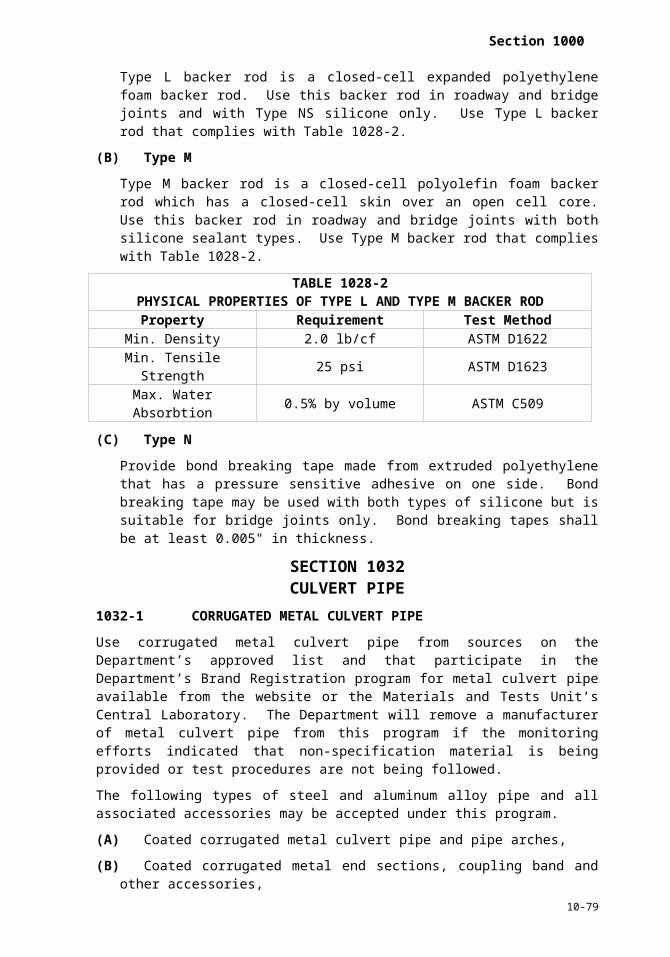
Section 1000
kind of seed involved or at any time that the condition of the seed appears to have deteriorated.
When a low percentage of germination causes the quality of the seed to fall below the minimum pure live seed specified, the Contractor may elect, subject to the approval of the Engineer, to increase the rate of application sufficiently to obtain the minimum pure live seed content specified, provided that such an increase in the rate of application does not cause the quantity of noxious weed seed per acre or square yard, as the case may be, to exceed the quantity that would be allowable at the regular rate of application.
Furnish and deliver each of the species or varieties of seed in separate bags. If seed is to be mixed before sowing, perform such mixing in a commercial seed mixing machine, or by an equally thorough means, after sampling and testing have been completed.
During handling and storing, care for the seed in such a manner that it will be protected from damage by heat, moisture, rodents or other causes.
1060-5 MULCH FOR EROSION CONTROL
Mulch for erosion control shall consist of grain straw, or other acceptable material, and be approved by the Engineer before being used. All mulch shall be reasonably free from mature seedbearing stalks, roots or bulblets of Johnson Grass, Nutgrass, Sandbur, Wild Garlic, Wild Onion, Crotalaria, Witchweed and an excessive amount of restricted noxious weeds as defined by the North Carolina Board of Agriculture at the time of use of the mulch. Loose and separate straw mulch that is matted or lumpy before being used.
Material for holding mulch in place shall be asphalt or other approved binding material.
1060-6 SPRIGS
Sprigs shall consist of freshly dug live stolons or rhizomes of permanent grasses, at least 2" in length, and be first class representatives of the required species or varieties specified in the specifications. The areas from which sprigs are to be obtained shall be free from Johnson Grass, Nutgrass, Sandbur, Wild Garlic, Wild Onion, Crotalaria, Witchweed and an excessive amount of restricted noxious weeds as defined by the North Carolina Board of Agriculture at the time of digging the sprigs. The areas shall have been mowed and raked, burned off, or otherwise prepared in a manner acceptable to the engineer before digging of sprigs begins.
1060-7 SOD
Sod shall consist of a live, dense, well-rooted growth of permanent grasses, free from Johnson Grass, Nutgrass, Sandbur, Wild Garlic, Wild Onion, Crotalaria, Witchweed and an excessive amount of restricted noxious weeds as defined by the North Carolina Board of Agriculture at the time of cutting the sod. Mow the area from which sod is to be obtained to a height of not more than 2". Rake free of grass clippings and debris and otherwise prepared in a manner satisfactory to the Engineer before cutting of sod begins.
Cut the sod into rectangular sections of sizes convenient for handling without breaking or loss of soil. Cut it with a sod cutter or other acceptable means to a depth that will retain in the sod practically all of the dense root system of the grass.
During wet weather, allow the sod to dry sufficiently before lifting to prevent tearing during handling and placing. During extremely dry weather, water it before lifting if such watering is necessary to insure its vitality and to prevent loss of soil during handling.
1060-8 MATTING FOR EROSION CONTROL
(A)General
Matting for erosion control shall be excelsior matting or straw matting. Furnish a Type 3 material certification in accordance with Article 106-3 certifying that the
10-79

Section 1060
matting meets this article. Other acceptable material manufactured especially for erosion control may be used when approved by the Engineer in writing before being used. Matting for erosion control shall not be dyed, bleached or otherwise treated in a manner that will result in toxicity to vegetation.
(B)Excelsior Matting
Excelsior matting shall consist of a machine produced mat of curled wood excelsior at least 47" in width and weigh 0.975 lb/sy with a tolerance of ± 10%. At least 80% of the individual excelsior fibers shall be 6" or more in length. Evenly distribute the excelsior fibers over the entire area of the blanket. Cover one side of the excelsior matting with an extruded plastic mesh. The mesh size for the plastic mesh shall be no more than 1" x 1".
(C)Straw Matting
Straw matting shall consist of a machine produced mat of 100% grain straw. The straw matting shall have a width of at least 48" and no more than 90" and weighing at least 0.50 lb/sy and no more than 0.75 lb/sy. Evenly distribute the straw over the entire area of the blanket. Cover one side of the blanket with photodegradable netting with a maximum mesh (netting) size of 0.75" x 0.75" sewn together with a degradable thread. The grain straw shall contain no weed seeds. Package each roll separately.
(D)Wire Staples
Staples shall be machine made of No. 11 gauge new steel wire formed into a U-shape. The size when formed shall be not less than 6" in length with a throat of not less than 1" in width.
1060-9 WATER
Water used in the planting or care of vegetation shall meet Class C fresh waters as defined in 15 NCAC 2B.0200.
1060-10 NURSERY GROWN PLANT MATERIALS
(A)General
Use all plants as called for by the contract.
Container grown plants may be used instead of balled and burlapped plants or bare rooted plants provided written approval for such use has been obtained from Engineer.
Grading of plants, size of root balls and type and minimum dimensions of containers shall conform to the American Standard for Nursery Stock. Do not cut back plants from larger sizes to meet the sizes called for in the contract.
Botanical names referred to in the contract are taken from Hortus Third, the Bailey Hortorium (MacMillan Publishing Co., Inc.). All plants delivered shall be true to name. Each plant, or group of the same species, variety and size of plant, shall be legibly tagged with the name and size of the plant.
All plants shall be first-class representatives of their species or varieties. The root system shall be vigorous and well developed. The branch systems shall be of normal development and free from disfiguring knots, sun scald injuries, abrasions of the bark, dead or dry wood, broken terminal growth or other objectionable disfigurements. Trees shall have reasonably straight stems and be well branched and symmetrical in accordance with their natural habits of growth.
All plants shall be free from plant diseases and insect pests. All shipments of plants shall comply with all nursery inspection and plant quarantine regulations of the states of origin and destination, as well as with Federal regulations governing interstate movement of
10-80

Section 1000
nursery stock. Any nursery stock used on highway landscape projects shall be accompanied by a valid copy of a certificate of inspection, which has been granted by the North Carolina Department of Agriculture, Entomology Division. Fire ant treatment certification, where applicable, is required.
When nursery stock from other states is used on projects in North Carolina, this stock shall be accompanied by a tag or certificate stating that the nursery stock has been inspected and certified by an authorized official of the state of origin as apparently free from injurious plant pests.
All plant materials are subject to inspection at any time by the Engineer. Any such inspection before or during planting operations, however, will not be construed as final acceptance of the plants involved.
All geophytes; bulbs, corms and tuberous plants; shall be synonymous to the term “plant” within the contract. Examples include, but are not limited to, Narcissi (Daffodil), Tulipa (Tulip), Iris and Canna; the terms “bulb”, “corm”, “tuber”; and specific plant names such as “Daffodil”, “Tulip”, “Canna lily”, etc.
(B)Balled and Burlapped Plants
Dig plants to be balled and burlapped so as to retain a firm ball of soil and the plant’s fibrous root system. The soil in the ball shall be the original and undisturbed soil in which the plant has been grown. Dig, wrap, transport and handle the plant so the soil in the ball shall not become frozen, loosened, cause stripping of the small feeding roots nor movements of the soil away from contact with such roots.
(C)Container Grown Plants
Container grown plants shall be healthy, vigorous, well-rooted and established in the container in which they are delivered. These plants shall be in the container long enough for the fibrous roots to have developed so the root mass will retain its shape and hold together when removed from the container. The container shall be sufficiently rigid to firmly hold the soil protecting the root mass during transporting, handling and planting. The soil shall not be allowed to become frozen.
(D)Bare Root Plants
Bare root plants shall have a heavy fibrous root system that has been developed by proper cultural treatment. Dig, package, transport and handle bare root plants in a manner that will prevent injury to or drying out of the trunks, branches or roots, or freezing of the roots. Bare root plants damaged through improper handling, freezing, drying out, etc. will result in rejection of material.
(E) Plant Substitution
No change in the Standard Specifications (species, variety, size, caliper, furnish) will be made without written approval of the Engineer. Present all requests for substitutions in writing and include a listing of the sources contacted in an attempt to secure specified plant material. Requests for substitutions shall include the botanical name, common name, cultivar, where applicable, size, caliper and furnish description of the proposed substitute. No increase in compensation will be made to the Contractor as a result of the use of approved substitute plants. The Department reserves the right to locate specified plant material for the project when it has knowledge that specified material is available.
(F)Geophytes
Geophytes; bulbs, corms and tuberous plants; shall be healthy and free of disease caused by fungi, nematodes, bacteria and wilt. Plants that are lightweight and lacking adequate mass will result in rejection. Plants shall be firm and absent of discolored patches with
10-81

Section 1060
soft or spongy areas or signs of rot, slime or mold. Plants with new root growth will result in rejection.
Dig, package, transport and handle these plants as to prevent injury, drying out, excessive wetness or freezing. Damaged plants through improper handling, freezing, drying out or excessive moisture will result in rejection.
All geophytes, bulbs, corms and tuberous plants shall be inspected for size and condition and rejected plants shall be removed from the supply before planting.
1060-11 MULCH FOR PLANTING
Use mulch for planting as specified in the specifications, shown in the plans, or approved by the Engineer. Mulch for planting shall not contain substances injurious to plants or which will inhibit normal development and growth of plants. Mulch for a project shall come from a single source, as approved by the Engineer, unless an additional source is submitted and approved before use.
1060-12 MATERIALS FOR STAKING OR GUYING
(A)Stakes
Use stakes made of cypress, cedar, oak, locust or other acceptable wood free from defects that would compromise the strength of the stake. Stakes shall be at least 2" x 2" (nominal). Use stakes of the size and length as shown in the plans.
(B)Wire
Wire shall be new soft No. 14 gauge steel wire or as shown in the plans.
(C)Hose
Hose to be used with wire shall have a minimum inside diameter of 1/2". All hose shall be garden type hose composed of rubber and fabric, or as shown in the plans.
(D)Other
Other staking and guying materials may be used if a sample is submitted and approved by the Engineer before use.
1060-13 HERBICIDES
The herbicide to be used for a particular application shall be as specified or approved by the Engineer.
Herbicides shall be properly labeled and registered with the United States Department of Agriculture and the North Carolina Department of Agriculture. A container shall contain only the herbicide that meets the analysis guaranteed on the label. Keep all herbicides in such original labeled containers until used.
Herbicide application shall only be conducted by individuals who possess a pesticide license from the NC Department of Agriculture or individuals under their direction and who has read, understands, and follows the herbicide labeling before applying the product.
1060-14 COIR FIBER MAT
Coir fiber mat shall consist of 100% coconut fiber (coir) twine woven into high strength matrix. The coir fiber mat shall have a thickness of at least 0.30" and weigh at least 20 oz/sy. The coir fiber mat shall have a tensile strength of at least 1,348 x 626 lb/ft and elongation of no more than 34% x 38%. The coir fiber mat shall have a flexibility of 65,030 x 29,590 mg-cm. The coir fiber mat shall have an observed flow velocity of 11 ft/sec. The coir fiber mat shall have a C-Factor of 0.002. The size of the coir fiber mat shall be 6.6 ft x 164 ft and the measured open area shall be 50%.
10-82

Section 1000
1060-15 SPECIAL STILLING BASIN
The special stilling basin shall be a bag constructed to a minimum size of 10 ft x 15 ft made from a nonwoven fabric. It shall have a sewn-in 8" (maximum) spout for receiving pump discharge. The bag seams shall be sewn with a double needle machine using a high strength thread. The seams shall have a minimum wide width strength of 60 lb/in tested in accordance with ASTM D4884.
SECTION 1070REINFORCING STEEL
1070-1 GENERAL
Store steel reinforcement on blocking at least 12" above the ground; protect the steel at all times from damage; and when placing in the work, ensure it is free from dirt, dust, loose mill scale, loose rust, paint, oil or other foreign materials.
1070-2 DEFORMED STEEL BAR REINFORCEMENT FOR STRUCTURES
Supply deformed steel bar reinforcement conforming to ASTM A615 for Grade 60. Bend and cut during fabrication with tolerances in accordance with the Manual of Standard Practice published by the Concrete Reinforcing Steel Institute. Bend the bars cold to the details shown in the plans.
Weld steel bar reinforcement only where shown in the plans or approved by the Engineer. When welding steel bar reinforcement use bars conforming to ASTM A706.
1070-3 COLD DRAWN STEEL WIRE AND WIRE REINFORCEMENT
Provide cold drawn steel wire for use as spirals or in fabricated form for the reinforcement of concrete meeting AASHTO M 32. Epoxy coat all spacers on spirals when the spirals are epoxy coated.
Use smooth welded wire reinforcement conforming to AASHTO M 55.
Use deformed welded wire reinforcement conforming to AASHTO M 221.
1070-4 REINFORCING STEEL BAR SUPPORTS
Make all wire bar supports of smooth cold drawn industrial quality basic wire having a minimum tensile strength of 65,000 psi. When the legs of the bar supports are in contact with the forms, ensure that the entire leg of the bar support is stainless steel wire or a minimum thickness of 1/4" stainless steel at points of contact with the forms. Use stainless steel wire meeting ASTM A493 except having a minimum chromium content of 16% and a minimum tensile strength of 95,000 psi. Ensure that wire sizes, height tolerance, and leg spacing for wire bar supports are in accordance with the Manual of Standard Practice published by the Concrete Reinforcing Steel Institute.
As an option to the stainless steel wire for the legs of bar supports at points of contact with the forms, provide legs of cold drawn steel wire plastic protected in accordance with the Manual of Standard Practice published by the Concrete Reinforcing Steel Institute, except provide plastic protection by dipping or by premolded plastic tips. Do not use plastic legs molded to the top wire.
Use plastic bar supports meeting the requirements listed in the Manual of Standard Practice published by the Concrete Reinforcing Steel Institute only when approved by the Engineer.
1070-5 PRESTRESSING STRAND
Use prestressing strands for use in prestressed concrete consisting of 7 wire strands, stress relieved after manufacture to remove internal stresses. Use the size and the grade of the strand as shown in the plans. Use strands conforming to AASHTO M 203 except provide
10-83

Section 1060
a specimen for test purposes, if required, from each reel of cable instead of each 20 ton production lot.
For precast prestressed deck panels, use 3/8” round seven-wire stress-relieved Grades 250 or 270 prestressing strands meeting AASHTO M 203.
Mark the outer layer of each reel pack of strand with a wide color band as follows: white for Grade 270 stress relieved strand, green for low relaxation strand, and a double marking of green and red for special low relaxation strand. In addition, attach a metal tag to each reel pack labeled in accordance with AASHTO M 203.
1070-6 DOWELS AND TIE BARS FOR PORTLAND CEMENT CONCRETE PAVEMENT
Use smooth plain round steel dowel bars conforming to AASHTO M 31 Grade 60. Do not use dowel bars with burred ends. A tolerance of ± 1/4" is permitted from the dowel length required by the plans. A straightness tolerance of 0.075" from a straight line is permitted.
Epoxy coat all dowel bars in accordance with AASHTO M 284 and these provisions, with a coating thickness of 7 to 13 mils after curing. Coated bars will be taken by the Engineer from the production run on a random basis at the point of coating application for testing and evaluation. The Engineer determines the sampling and testing schedule for the number and frequency of tests for thickness of coating, adhesion of coating and holidays. At least one bar for each 20 coated is tested for holidays and coating thickness. Perform at least 2 bend tests for each 8 hours of production coating or any fraction thereof for determining that adhesion and flexibility of the coating meets specification requirements. Payment is not made by the Department for coated bars selected for testing and evaluation purposes at the point of coating application. All coated bars are inspected at both the coating and fabrication shops. Furnish a Type 1 material certification in accordance with Article 106-3 and attach it to a completed Reinforcing Steel Certification, M&T Form 913, for all coated reinforcing bars before cleaning and coating operations, of the time and location where the work is performed. A blank Reinforcing Steel Certification, M&T Form 913, may be obtained from the Materials and Tests Unit.
Use dowel assemblies for supporting dowel bars of rigid construction capable of holding the dowel bars in proper position during placing of concrete, and of such design to permit unrestricted movement of the pavement slab. Use wire for dowel assemblies meeting AASHTO M 32. Use a dowel assembly that holds the dowels in the required position within a tolerance of ± 1/4" in vertical and horizontal planes. Obtain written approval for the dowel assembly before use.
Coat dowel bars and the entire dowel assembly with an approved wax base coating. Apply the coating by dipping or spraying such that the wax coating on the dowel bars is of uniform thickness sufficient to allow pulling of the dowel from the concrete as provided in AASHTO T 253 and M254. Furnish to the Department for testing one dowel basket assembly for each 200 assemblies incorporated into the project.
Use deformed tie bars conforming to AASHTO M 31 for Grade 40 or Grade 60.
1070-7 EPOXY COATED REINFORCING STEEL
(A)General
Coaters of epoxy coated reinforcing steel shall establish proof of their competency and responsibility in accordance with the Concrete Reinforcing Steel Institute’s Fusion Bonded Epoxy Coating Applicator Plant Certification Program. Registration and certification of the plant or shop under the CRSI Program and submission of the valid annual certificate to the State Materials Engineer is required before beginning any coating. The same requirement applies to coaters subcontracting work from the coater directly employed by the contractor.
10-84

Section 1000
Obtain approval of each coater and/or fabricator of epoxy coated reinforcing steel before coating or fabricating bars. Approval is based upon the following:
(1) The coating applicator and/or fabricator establishing and maintaining an effective quality control program and
(2) The coating applicator having equipment for cleaning, coating and/or fabricating that produces coated material conforming to these Standard Specifications.
Include in requests for approval a well defined quality control program and direct the requests to the State Materials Engineer. Before Department approval is issued, the condition of equipment for blast cleaning, coating and/or fabricating material is evaluated by the Engineer for determining the equipment capability of producing a coated product conforming to the Standard Specifications. Lists of Department approved epoxy coating and fabricating companies are available from the State Materials Engineer.
(B)Coating Materials
Obtain approval for the epoxy resin powder before use. A list of prequalified powder sources is available from the State Materials Engineer.
Submit prequalified products other than those now approved for use to the State Materials Engineer for approval. Requalify each product every 5 years and any time a change is made in the manufacturing process or chemical composition of the epoxy resin.
Use powdered resin of any color that provides contrast to the corroded or uncorroded surface of the steel. Provide material of the same quality as that used for prequalification tests and as represented by test reports forwarded to the State Materials Engineer.
Ensure the manufacturer of the epoxy resin supplies to the coating applier information on the resin that is essential to the proper use and performance of the resin as a coating. Ensure the manufacturer of the resin furnish the coating applier a written certification signed by a responsible officer of the company that the material furnished for coating the reinforced steel is the same formulation as that for which test reports were previously submitted to the State Materials Engineer.
With each batch of coating material, furnish a written certification by the coating applier to the Engineer which properly identifies the batch number, material, quantity represented, date of manufacture, name and address of manufacturer and includes a statement that the supplied coating material is the same composition as that prequalified.
(C)Patching Material
Ensure the epoxy resin manufacturer supplies a prequalified and approved patching or repair material that is compatible with the coating and inert in concrete. Ensure that the material is suitable for making repairs with a minimum dry film thickness of 6 mils from 2 coats on damaged areas of the coating. Ensure that each coater, fabricator and contractor has a copy of the manufacturer’s written instructions for application of the patching material and the instructions are closely followed during coating damage repairs.
Apply 2 coats of patch material where needed with the second coat applied only after the first coat dries to the touch. Do not apply any patch material when the surface temperature of the steel or the air temperature is below 40°F. Do not ship or place steel until the patch material is dry to the touch.
10-85

Section 1060
(D)Reinforcing Steel
Use coated steel reinforcing bars meeting AASHTO M 31, Grade 60 and free of contaminants such as oil, grease and paint. Use bars free of surface irregularities that produce holidays in the coating. Ensure the coater visually inspects the bars to avoid coating bars containing such surface irregularities. If the coater fails to detect surface irregularities that produce holidays in the coating, patch the holidays with 6 mils of patching material as specified in Subarticle 1070-7(C) to avoid rejection of the bars.
(E) Surface Preparation of Bars
Subject coated reinforcing steel surfaces to a very thorough blast (near white) cleaning, before coating. Ensure that the appearance of the surface after cleaning corresponds to ASTM D2200 and the pictorial standards of SSPC-VIS 1, degree of cleaning SSPC-SP 10. Produce a suitable anchor pattern profile by the cleaning media. A target profile depth of 1/3 of the coating thickness is considered a suitable anchor pattern.
Apply the coating to the cleaned surface as soon as possible after cleaning. Remove any formation of rust blooms on the cleaned bars by blast cleaning before application of the coating. However, never delay the coating more than 8 hours after cleaning unless otherwise permitted. Provide surface characteristics of the steel as described above at the time of coating.
After blast cleaning, and before application of the coating, remove all visible traces of grit and dust from the bars.
(F)Application of Coating
Apply the coating as an electrostatically charged dry powder sprayed into the grounded steel bar using an electrostatic spray gun. Apply the powder to either a hot or cold bar. Give the coated bar a thermal treatment as specified by the manufacturer of the epoxy resin that provides a fully cured and bonded finish coating. Control temperature as recommended by the manufacturer of the coating material to ensure a workmanlike finish without blistering or other defects. Completely coat all bars, including bar ends, with epoxy resin powder to the minimum thickness specified in Subarticle 1070-7(G).
Run the production line at such a speed as to provide proper cure time before quench by air or water.
(G)Quality Control Requirements
For acceptance purposes, ensure that each recorded film thickness measurement is in the range of 7 to 12 mils after cure, with the entire area of a bar having a minimum coating thickness of 7 mils.
A single recorded coated reinforcing bar thickness measurement is the average of 3 individual readings obtained from 3 adjacent areas on the body of the bar (3 adjacent areas between deformations). Obtain at least 5 recorded measurements approximately evenly spaced along each side of the test bar (at least 10 recorded measurements per bar).
Ensure the coating applier visually inspects each coated bar after cure for continuity of coating and to ensure that the coating is free of holes, voids, contamination, cracks and damaged areas discernible to the unaided eye. In addition, no more than an average of 2 holidays per linear foot of bar are permitted providing the total quantity of holidays does not exceed 5 in any linear foot. Bars that contain no more than 5 holidays in any linear foot of bar are acceptable provided any holidays in excess of 2 per linear foot are coated with 6 mils of patching material specified in Subarticle 1070-7(C). Retest the bars after patching to confirm that no more than 2 holidays exist in any linear foot of bar.
10-86

Section 1000
Ensure the coating applier evaluates the adhesion of the coating on a representative number of bars selected by the Engineer from each proposed shipment as specified in Subarticle 1070-7(L). No visible cracks or disbonding of the coating are allowed when tested in accordance with Subarticle 1070-7(H).
(H)Test Methods Required of the Coater
The thickness of the coating is measured on the body of the bar between the deformations or ribs. Conduct non-destructive coating thickness measurements using magnetic gauges in accordance with ASTM G12, with the following additions applicable to commercially available pull-off gauges, and to fixed probe gauges with a magnetic field of vision not exceeding 0.015" of steel depth; 0.015" is the minimum thickness of smooth steel to which adding more material does not change the zero reading.
Perform gauge calibration with shims on a smooth, clean low-carbon steel plate with minimum dimensions of 3" x 3 1/2", rather than on a cleaned reinforcing bar.
Determine a correction factor defining the effect of the bar preparation process as the difference between (a) the average of 10 gauge readings on a cleaned, but uncoated reinforcing bar of the size and lot coated, and (b) the average of 5 gauge readings on a smooth mild steel plate. This correction factor is then subtracted from all subsequent gauge readings on coated bars.
TABLE 1070-1BEND TEST REQUIREMENTS
Bar No. Mandrel Diameter, inch3 34 45 56 67 78 89 910 1011 1114 1718 23
Fixed probe gauges are checked to ensure that the force generated by the springloaded probe housing is sufficient to ensure intimate contact between the probe tip and the coatings of the curved bar surface. If intimate contact does not result, remove the probe housing and use hand pressure to obtain valid indicated thickness readings.
As an option, use thumbwheel pulloff gauges to provide valid thickness measurements on coated reinforcing bars with a deformation spacing which is less than the maximum outer dimensions of the probe housing. Position the base of the probe housing against the top of 2 adjacent deformations and extend the probe through the air gap to the body of the bar. Hold the gauge very steady and apply continuous light downward pressure to the housing during the measurement.
Use a 67.5V holiday detector equipped with a holiday marker in accordance with the detector manufacturer’s instructions. Maintain the detector in perfect working condition at all times during the bar coating process. Immediately after coating, route each bar through the detector for holiday detection. Bars containing more than five holidays in a linear foot of bar or averaging more than 2 holidays per foot of bar are either rejected or cleaned, recoated, and retested for holidays. A coating holiday for the purpose of this
10-87

Section 1060
specification is defined as a discontinuity in the applied coating that occurs during the coating process that is detected either visually or electromechanically.
The adhesion of the coating is evaluated by bending production coated bars 120° (after rebound) around a mandrel of specified size as prescribed in Table 1070-1. Conduct the bend test at a uniform rate and take up to 90 seconds to complete. Place the 2 longitudinal deformations in a plane perpendicular to the mandrel radius, and maintain the test specimen at thermal equilibrium between 68°F and 85°F. If the specimen for the adhesion of coating shows evidence of cracking or debonding of the coating, conduct 2 retests on random samples. If the results of both retests meet the specified requirements, the coated bars represented by the samples are acceptable.
The fracture or partial failure of the steel-reinforcing bar in the bend test for adhesion of coating is not considered as an adhesion failure of the coating. If failure of the bar occurs, test 2 check samples without bar failure.
Condition test bars at a temperature range of 68°F to 85°F. In cases of dispute, conduct tests at 73°F and 50% relative humidity in accordance with recommended practices in ASTM D3451.
(I) Handling and Identification
Provide padded contact areas for all systems for handling coated bars at the coating plant, fabricator and project. Pad or suitably band all bundling bands to prevent damage to the coating. Lift all bundles of coated bars with a strong back, spreader bar, multiple supports or a platform bridge to prevent bar-to-bar abrasion from sag in the bundles of coated bars.
(J) Fabrication of Steel-Reinforcing Bars After Coating
Protect drive rolls and automatic kick-off levers on shear beds, and drive pins, center pins and back-up barrels on benders with a suitable covering to minimize damage during the fabrication process. Note that these Standard Specifications permit no more than 5% of the surface area of a bar to contain patching material. This includes patching due to damage to the coating by the coater, fabricator, transporter and contractor.
Store coated bars as required by Subarticle 1070-7(M).
Ensure the fabricator maintains the identification of the coated bars and that the coated, fabricated bars are identified with proper tags for final shipment to the job site.
Perform coating repairs as described in Subarticle 1070-7(K) with material specified in Subarticle 1070-7(C).
Flame cutting of coated bars to the required dimensions is not permitted. Maintain any mechanical device used for cutting the coated bars to required length in good working order to minimize damaging the coating in the vicinity of the cut ends. Repair coating damage in these areas as described in Subarticle 1070-7(K) with material specified in Subarticle 1070-7(C).
(K)Procedures for Repair of Coating
Repair all coating damage of the reinforcing bars with material described in Subarticle 1070-7(C) when coating bond loss and damage exist, including crushed coating and hairline cracking if bare metal is evident. When repair is required, clean and repair all damage. Remove crushed coating and loose or deleterious material. In areas where rust is present, remove it by wire brushing with a power tool to the surface finish specified in Subarticle 1070-7(E) before repair.
10-88

Section 1000
(L) Inspection by the Department
Coated bars are inspected at both the coating and fabrication shops unless otherwise approved. The coater and/or fabricator shall furnish Type 3 material certification in accordance with Article 106-3, attached to a completed Reinforcing Steel Certification, M&T Form 913, for all coated reinforcing bars. Include a completed Epoxy Coated Reinforcing Bar Inspection Report, Form 310, with each shipment. These certification forms are available from the State Materials Engineer. Do not epoxy coat, fabricate or ship reinforcing steel to the project site without the approval of the Engineer.
Provide free entry to the plant and facilities of the coater and/or fabricator for the inspection of all manufacturing processes including, but not limited to, the cleaning, coating and fabrication of the ordered bars.
On a random basis, lengths of coated bars or fabricated bars are taken from the production run at the point of coating application for testing and evaluation.
All bar tests are made at the coating applicator and/or fabricator’s plant, before shipment, unless otherwise approved. Ensure the coating applier and/or fabricator notify the State Materials Engineer 5 working days before the time the material is coated or fabricated. Do not ship bars until they are inspected and tagged by the Department.
The Engineer randomly selects 3 coated bars of each size from each proposed shipment to test for holidays, damage and coating thickness. If any bar fails to conform to these Specification requirements, 6 samples are selected and tested. If these tests reveal that the coating conforms to Specification requirements the shipment is acceptable. If any of the second set of samples fail to conform to these Specifications the coater is required to test all bars of that size that are included in the shipment and re-submit the shipment to the Department for inspection. The Engineer selects from each proposed shipment 2 samples of each size bar for bend tests by the coater for determining that the adhesion and flexibility of the coating conforms to Subarticle 1070-7(H).
(M) Repairs to Coating Due to Loading, Transporting and Handling
Transport the bundled bars from the coater or fabricator to the project site with padding, such as carpet padding or used carpet, placed over each bundle of steel upon which another bundle of steel is placed unless wooden spacers are placed between each bundle to prevent contact.
Load all bundles of bars horizontally for transporting. Transport the bars on a flatbed trailer. Do not allow the length of bars extending beyond the trailer bed to exceed 8 ft.
Repair coating damage due to handling and transporting or other causes with material specified in Subarticle 1070-7(C) and in accordance with Subarticle 1070-7(K).
(N)Rejection
Coated bars that do not meet the Standard Specifications are rejected. At the Contractor’s option, replace coated bars containing defects beyond the limits of the Standard Specifications. Alternatively, strip the bars of coating, reclean and recoat in accordance with the Standard Specifications.
1070-8 SPIRAL COLUMN REINFORCING STEEL
Furnish spiral column reinforcing steel with the following areas and weights as required in Table 1070-2 and in the plans.
10-89

Section 1060
TABLE 1070-2SPIRAL COLUMN REINFORCEMENT STEEL PROPERTIES
Material Size Area, sq.in. Weight, lb/ftPlain Cold Drawn Wire W 20 0.20 0.668
W 31 0.31 1.043Deformed Cold Drawn Wire D-20 0.20 0.680
D-31 0.31 1.054Plain or Deformed Bar #4 0.20 0.668
#5 0.31 1.043
Use cold drawn wire conforming to AASHTO M 32. Use plain or deformed bars conforming to AASHTO M 31 for Grade 60. Use deformed cold drawn wire conforming to AASHTO M 225.
The diameter of the spiral reinforcing steel is the outside to outside measurement of the bars or wire, with an allowance of 1/2" more or 1/2" less than the specified diameter as shown in the plans.
Furnish spirals with 1.5 extra turns at top and at bottom of the completed spiral cage. Where splicing of the spirals is necessary other than those shown in the plans, provide a minimum lap splice of 3 ft.
Do not weld on the spiral reinforcing steel.
When required by the plans, use epoxy coated spiral column reinforcing steel including spacers in accordance with Article 1070-7.
Use the minimum number of spiral spacers as shown in the plans. Ensure a minimum section modulus per spiral spacer of 0.030 cu.in.
1070-9 MECHANICAL BUTT SPLICES
When called for by the contract or when directed by the Engineer, use a mechanical butt reinforcing steel splice from an approved source. Use a standard metal filled sleeve, cement mortar filled sleeve, threaded steel couplings, forged steel sleeve or cold-forged sleeve. An exothermic process whereby molten filler metal, contained by a high strength steel sleeve of larger inside diameter than the bars, is introduced into the annular space between the bars and the sleeve and between the ends of the bars may be used. Provide a splice that is capable of transferring at least 125% of the yield strength of the bars from one bar to the other by the mechanical strength of the splice components.
For splices not on the approved list, before use and as a condition of approval, assemble 3 test splices in the presence of the Engineer for each size of bar which is proposed for use on the project. Forward the test splices to the Materials and Tests Unit in Raleigh, NC for testing and approval.
SECTION 1072STRUCTURAL STEEL
1072-1 GENERAL
Furnish and fabricate all structural steel and related incidental materials including sign supports and high mount lighting standards and use materials in accordance with this section.
(A)Fabricator Qualification
Use steel fabricators on the Department’s Approved Structural Steel Fabricators List for the type work being performed. The list is available from the Materials and Tests Unit or on the Department’s website.
10-90

Section 1000
Employ fabricators of high mount lighting standards in excess of 80 ft in length, structural steel components of fender systems, retaining walls and noise walls, sign supports, sign structures, pot and expansion bearings, simple span rolled beams, including those requiring cover plates, solar array platforms and modular expansion joints that are AISC certified in Simple Steel Bridges. Employ fabricators of heat curved rolled beams, rolled beams for continuous spans and plate girders that are AISC certified in Major Steel Bridges. Employ fabricators of fracture critical bridge beams and girders that have a Fracture Critical Members Endorsement from AISC. Ensure that fabricators, applying over 1,500 sf of coating for each project, have a Sophisticated Paint System Endorsement from AISC or a Quality Procedure 3 Certification from the Society of Protective Coatings.
When AISC certification is required, submit proof of registration and certification of the plant or shop under the AISC program to the State Materials Engineer before beginning fabrication and on an annual basis. The same requirements apply to fabricators subcontracting work from the fabricator directly employed by the Contractor.
(B)Office
Ensure that fabricators of main structural steel components of bridges provide an office area with an approximate floor space of 100 sf, a desk or drafting table, 2 chairs, telephone, facilities for proper heating and cooling, telephone, separate dial-up or faster internet access and adequate lighting and located at the plant site for the exclusive use of the Engineer. Ensure fabricators of other structural steel items furnish reasonable work areas for the Engineer.
1072-2 SHAPES, PLATES, BARS AND SHEETS
Use shapes, plates, bars and sheets meeting AASHTO M 270 Grade 36 unless otherwise required by the contract. For painted beams or girders, use sheet material of 1/32" in thickness meeting ASTM A1008 or A1011, and sheet material of 1/16" through 5/32" thickness meeting ASTM A1011 for Grades 36, 40 or 45. For unpainted beams or girders, use sheet material less than 3/16" thickness meeting ASTM A606 for Type 4.
1072-3 BEARING PLATE ASSEMBLIES
Unless otherwise shown in the plans, galvanize steel bearing assemblies for both structural steel beams and girders and prestressed concrete girders. Galvanize anchor bolts, nuts and washers in accordance with AASHTO M 232. Cut pipe sleeves and collars from Schedule 40 PVC pipe meeting ASTM D1785.
Except for attachments of bearing plates to beams, fabricate and weld bearing plate assemblies before galvanizing the steel. Seal all joints of welded parts with weld material. After the fabrication of the bearing plate assembly is complete, galvanize the assembly in accordance with AASHTO M 111. For prestressed concrete girders, clean welds made for attaching bearing plates to beams or girders and give them 2 coats of organic zinc repair paint having a minimum total coating thickness of 3 dry mils. For steel beams and girders, clean and paint in accordance with Article 442-10.
Repair galvanized surfaces that are abraded or damaged at any time after the application of the zinc coating by thoroughly wire brushing the damaged areas and removing all loose and cracked coating, after which give the cleaned area 2 coats of organic zinc repair paint having a minimum total coating thickness of 3 dry mils.
Use zinc rich paint meeting Article 1080-9.
1072-4 ANCHOR BOLTS
Unless otherwise stated herein, use anchor bolts meeting ASTM A307 for Grade A.
10-91

Section 1060
Provide anchor bolts for bearing plate assemblies meeting ASTM A449.
Swedge anchor bolts for a distance equal to the embedment length minus 3" measured from the embedded end.
Hot-dip galvanize anchor bolts, nuts and washers in accordance with AASHTO M 232.
1072-5 HIGH STRENGTH BOLTS, NUTS AND WASHERS
(A)General
Furnish all high-strength bolts, nuts and washers, including direct tension indicators, in accordance with the appropriate AASHTO or ASTM materials specifications as amended and revised herein.
Furnish the Engineer a copy of the manufacturer’s test report for each component. Ensure the report indicates the testing date, the city and state where the components were manufactured, the lot number of the material represented, the rotational capacity tests lot number and the source identification marking used by the manufacturer of each component. On test reports for direct tension indicators, include the tension load at which indicators are tested, gap clearance, nominal size and coating thickness.
Produce each permanent fastener component installed in a structure from domestically processed material containing the grade identification markings required by the applicable reference specification and the manufacturer’s source identification marking. A copy of the source identification marking used by each manufacturer is on file with the Department’s Materials and Tests Unit.
Obtaining permanent bolts, nuts and washers in any one structure from different manufacturers is allowed provided:
(1) All bolts are produced by only one manufacturer.
(2) All nuts are produced by only one manufacturer.
(3) All washers are produced by only one manufacturer.
Have all fasteners used in a structure furnished by the fabricator of the steel. Require the fabricator to submit the fasteners for sampling and testing at least 5 weeks before delivery to the project site. Sample and test each diameter and length of bolt, nut and washer assembly in accordance with Table 1072-1.
TABLE 1072-1SAMPLING REQUIREMENTS FOR
HIGH STRENGTH BOLTS, NUTS AND WASHERSLot Quantity Number of Samples
0-800 3 Assemblies801-8000 6 Assemblies
> 8000 9 Assemblies
Ship only those fasteners to the project that are sampled, tested and approved. Protect the material from moisture during storage such that it does not contain any indication of rust at the time of installation. Ensure that each component contains a thin coat of lubricant at the time of installation.
When galvanized high strength bolts are required, use bolts, nuts and washers meeting Subarticle 1072-5(F).
When corrosion resistant structural steel is required by the plans, provide fasteners with atmospheric corrosion resistance and weathering characteristics comparable to that of the structural steel.
10-92

Section 1000
(B)Specifications
Ensure that all bolts meet ASTM A325.
Ensure that all nuts meet ASTM A194 as applicable or ASTM A563. Completely coat each nut with a wax lubricant.
Ensure that all washers meet ASTM F436.
Ensure that all direct tension indicators meet ASTM F959.
(C)Manufacturing
(1) Bolts
Hardness for bolt diameters 1/2" to 1" inclusive shall be 248 to 311 Brinell hardness and 24 to 33 Rockwell C hardness.
(2) Nuts
(a) Heat treat galvanized nuts to Grades 2H, DH or DH3.
(b) Use plain (ungalvanized) nuts of Grades 2, C, D or C3 with a minimum Rockwell hardness of 89 HRB or Brinell hardness of 180 HB, or heat treat to Grades 2H, DH or DH3. The hardness requirements for Grades 2, C, D and C3 exceed the current AASHTO/ASTM requirements.
(c) Tap oversize galvanized nuts the minimum amount required by ASTM A563. Overtap the nut such that the nut assembles freely on the bolt in the coated condition and meets mechanical requirements of ASTM A563 and the rotational-capacity test herein.
(3) Mark all bolts, nuts and washers in accordance with the appropriate AASHTO/ASTM Specifications.
(4) Direct Tension Indicators
(a) For Type 3 high strength bolts, mechanically galvanize direct tension indicators to ASTM B695, Class 55, and then apply baked epoxy to a thickness of 1 mil minimum. Direct tension indicators need not be mechanically galvanized or epoxy coated if they are made from material conforming to ASTM A325, Type 3 bolts.
(b) For plain Type 1 high strength bolts, provide direct tension indicators that are plain or mechanically galvanized to ASTM B695, Class 55.
(c) For galvanized Type 1 high strength bolts, mechanically galvanize direct tension indicators to ASTM B695, Class 55.
(D)Testing
(1) Bolts
(a) Proof load tests in accordance with ASTM F606, Method 1, are required at the minimum frequency as specified in AASHTO M 164, Paragraph 9.2.4.
(b) Wedge tests on full size bolts in accordance with ASTM F606, Paragraph 3.5, are required. If bolts are galvanized, perform the tests after galvanizing. Test at a minimum frequency as specified in AASHTO M 164, Paragraph 9.2.4.
(c) If galvanized bolts are supplied, measure the thickness of the zinc coating. Take measurements on the wrench flats or top of bolt head.
(2) Nuts
10-93

Section 1060
(a) Proof load tests in accordance with ASTM F606, Paragraph 4.2, are required at the minimum frequency of as specified in ASTM A563 and ASTM A194. If nuts are galvanized, perform the tests after galvanizing, overtapping and lubricating.
(b) If galvanized nuts are supplied, measure the thickness of the zinc coating. Take measurements on the wrench flats.
(3) Washers
(a) If galvanized washers are supplied, perform hardness testing after galvanizing.
(b) Remove the coating before taking hardness measurements.
(c) If galvanized washers are supplied, measure the thickness of the zinc coating.
(d) Test direct tension indicators in accordance with ASTM F959.
(4) Assemblies
Rotational-capacity tests are required. Ensure the manufacturer or distributor perform such tests on all black or galvanized (after galvanizing) bolt, nut and washer assemblies before shipping. Washers are required as part of the test.
The following applies:
(a) Except as modified herein, perform the rotational-capacity test in accordance with ASTM A325.
(b) Test each combination of bolt production lot, nut lot and washer lot as an assembly. Where washers are not required by the installation procedures, do not include in the lot identification.
(c) Assign a rotational-capacity lot number to each combination of lots tested.
(d) The minimum frequency of testing is 2 assemblies per rotational-capacity lot.
(e) Assemble the bolt, nut and washer assembly in a Skidmore-Wilhelm Calibrator or an acceptable equivalent device (This requirement supersedes the current ASTM A325 requirement to perform the test in a steel joint). For short bolts that are too short for assembly in the Skidmore-Wilhelm Calibrator, see Subarticle 1072-5(D)(4)(i).
(f) The minimum rotation, from a snug tight condition (10% of the specified proof load), is: 240° (2/3 turn) for bolt lengths less than 4 diameters; 360° (1 turn) for bolt lengths greater than 4 diameters and less than 8 diameters; 480° (1 1/3 turn) for bolt lengths greater than 8 diameters.
(g) These values differ from the AASHTO M 164 Table 8 specifications.
(h) Achieve tension at the above rotation equal to or greater than 1.15 times the required installation tension. The installation tension and the tension for the turn test are shown in Table 1072-2.
TABLE 1072-2BOLT TENSION REQUIREMENTS
Diameter, inch 1/2" 5/8" 3/4" 7/8" 1" 1 1/8"
1 1/4"
1 3/8"
1 1/2"
Req. Installation Tension, kips 12 19 27 39 51 56 71 85 103
Turn Test Tension, kips 14 22 32 45 59 64 82 98 118
10-94

Section 1000
(i) After the required installation tension listed in Table 1072-2 is exceeded, one reading of tension and torque is taken and recorded. The torque value shall conform to the following equation:
Torque ≤Where:
Torque = measured torque in foot-poundsP = measured bolt tension in poundsD = bolt diameter in feet
For bolts that are too short to test in a Skidmore-Wilhelm Calibrator, test in a steel joint. The tension requirement of Subarticle 1072-5(D)(4)(h) is computed using a value of P equal to the turn test tension shown in the Table 1072-2.
(5) Reporting
(a) Record the results of all tests, including zinc coating thickness, required herein and in the appropriate AASHTO specifications on the appropriate document.
(b) Report the location where tests are performed and date of tests on the appropriate document.
(6) Witnessing
Witness of the test by an inspection agency is not required; however, ensure the manufacturer or distributor performing the tests certifies that the recorded results are accurate.
(7) Documentation
(a) Mill Test Report(s)
(i) Furnish Mill Test Report(s) for all mill steel used in the manufacture of the bolts, nuts or washers.
(ii) Indicate in the Mill Test Report the place where the material was melted and manufactured, the lot number of the material represented and the source identification used by the manufacturer.
(b) Manufacturer Certified Test Report(s)
(i) Have the manufacturer of the bolts, nuts and washers furnish Manufacturer Certified Test Report(s) for the item furnished.
(ii) Include in each Manufacturer Certified Test Report the relevant information required in accordance with Subarticle 1072-5(D)(5).
(iii) Have the manufacturer performing the rotational-capacity test include on the Manufacturer Certified Test Report:
A) The lot number of each of the items tested.
B) The rotational-capacity lot number as required in Subarticle 1072-5(D)(4)(c).
C) The results of the tests required in Subarticle 1072-5(D)(4).
D) The pertinent information required in Subarticle 1072-5(D)(5)(b).
E) A statement that the Manufacturer Certified Test Report for the items are in conformance to the Standard Specifications and the appropriate AASHTO specifications.
10-95

Section 1060
F) The location where the bolt assembly components were manufactured.
(c) Distributor Certified Test Report(s)
(i) Ensure that the Distributor Certified Test Report(s) includes Manufacturer Certified Test Reports above for the various bolt assembly components.
(ii) Ensure the rotational-capacity test is performed by a distributor or a manufacturer and reported on the Distributor Certified Test Report.
(iii) Include in the Distributor Certified Test Report the results of the tests required in Subarticle 1072-5(D)(4).
(iv) Include in the Distributor Certified Test Report the pertinent information required in Subarticle 1072-5(D)(5)
(v) Include in the Distributor Certified Test Report the rotational-capacity lot number as required in Subarticle 1072-5(D)(4)(c).
(vi) Ensure that the Distributor Certified Test Report certifies that the Manufacturer Certified Test Reports are in conformance to this Standard Specifications and the appropriate AASHTO specifications.
(E) Shipping
(1) Ship bolts, nuts and washers, where required, from each rotational-capacity lot in the same container. If there is only one production lot number for each size of nut and washer, shipping of the nuts and washers in separate containers is allowed. Permanently mark each container on the side with the rotational-capacity lot number such that identification is possible at any stage before installation.
(2) Provide the appropriate MTR and MCTR or DCTR to the contractor or owner as required by the contract.
10-96

Section 1000
Figure 1072-1. Bolt and nut description. Bolt and nut marking varies. Refer to Subarticle 1072-5(B). F is the width across the flats of the bolt. H is the height of the bolt or nut. Nuts may be washer facing as in (a) or double chamfered as in (b). D is the bolt diameter and nominal bolt size. W is the width across the flats of the nut.
TABLE 1072-3HIGH STRENGTH BOLTS
BOLT AND NUT DIMENSIONS
Nominal Bolt Size, inch
Heavy Hexagon Structural Bolt Dimensions, inch
Semi-Finished HeavyHexagon Nut
Dimensions, inchWidth Across
Flats Height Thread Length
Width Across Flats Height
(D) (F) (H) (Thread) (W) (H)1/2 7/8 5/16 1 7/8 31/645/8 1 1/16 25/64 1 1/4 1 1/16 39/643/4 1 1/4 15/32 1 3/8 1 1/4 47/647/8 1 7/16 35/64 1 1/2 1 7/16 55/641 1 5/8 39/64 1 3/4 1 5/8 63/64
1 1/8 1 13/16 11/16 2 1 13/16 1 7/641 1/4 2 25/32 2 2 1 7/321 3/8 2 3/16 27/32 2 1/4 2 3/16 1 11/321 1/2 2 3/8 15/16 2 1/4 2 3/8 1 15/32
10-97
Thread
Bolt LengthHF W H
(a)H(b)
D
Nut MarkingsBolt Markings

Section 1060
TABLE 1072-4HIGH STRENGTH BOLTS WASHER DIMENSIONS
Bolt Size D,
inch
Circular Washers Dimensions, inch
Square or Rectangular Beveled Washers Dimensions for American
Standard Beams and Channels, inch
Nominal Outside
Diameter
Nominal Diameter of Hole
Thickness Min.
Thickness Max.
Minimum Side
Dimension
Mean Thickness
Slope of Taper in
Thickness1/2 1 1/16 17/32 .097 .177 1 3/4 5/16 1:65/8 1 5/16 11/16 .122 .177 1 3/4 5/16 1:63/4 1 15/32 13/16 .122 .177 1 3/4 5/16 1:67/8 1 3/4 15/16 .136 .177 1 3/4 5/16 1:61 2 1 1/8 .136 .177 1 3/4 5/16 1:6
1 1/8 2 1/4 1 1/4 .136 .177 2 1/4 5/16 1:61 1/4 2 1/2 1 3/8 .136 .177 2 1/4 5/16 1:61 3/8 2 3/4 1 1/2 .136 .177 2 1/4 5/16 1:61 1/2 3 1 5/8 .136 .177 2 1/4 5/16 1:61 3/4 3 3/8 1 7/8 .178A .28A - - -
2 3-3/4 2-1/8 .178A .28A - - -Over 2
to 4 Incl.
2D-1/2 D+1/8 .24B .34B - - -
A. 3/16" nominalB. 1/4" nominal
(F)Galvanized High Strength Bolts, Nuts and Washers
Use galvanized high strength bolts, nuts and washers meeting all other requirements of this subarticle except as follows:
(1) Use Type 1 bolts.
(2) Quench and temper washers.
(3) Mechanically galvanize in accordance with ASTM B695, Class 55.
(4) Ship galvanized bolts and nuts in the same container.
(5) Use organic zinc repair paint for touch-up of galvanized surfaces meeting Article 1080-9.
(6) Include in manufacturer’s test reports results of the zinc coating thickness measurements.
(7) Have each galvanized nut coated with a wax lubricant with a color contrast to that of the zinc coating.
1072-6 WELDED STUD SHEAR CONNECTORS
Use Type B shear studs in accordance with the Bridge Welding Code as defined in Article 1072-18.
Use and install welded stud shear connectors meeting Article 1072-18. Ensure that shear studs and the areas of beams, girders or other structural steel to which the studs are welded are free of rust, rust pits, oil, grease, moisture, paint, galvanizing, loose mill scale or other deleterious matter which adversely affects the welding operation. Apply shear studs on steel with tightly adhering mill scale as determined by the Engineer provided acceptable results are achieved and the installed studs meet the Bridge Welding Code.
10-98

Section 1000
1072-7 INSPECTION
(A)General
Give the Materials and Tests Unit 72 hours notice for in-state producers and 192 hours notice for producers out-of-state before beginning work in the shop. Do not manufacture or fabricate any material, other than stock items, before the Materials and Tests Unit is notified and the final shop drawings are reviewed, accepted and returned to the fabricator.
The contractor/fabricator shall be responsible for and shall be required to perform all quality control procedures and nondestructive testing in accordance with the Bridge Welding Code as defined in Article 1072-18 and as required by the contract. Perform all quality control procedures and nondestructive testing in the presence of the Department’s inspector unless otherwise approved by the Department’s inspector. Obtain approval for all quality control inspectors from the Department’s inspector and ensure their qualification in accordance with the Bridge Welding Code. Maintain all QC reports as required by the Bridge Welding Code, including, but not limited to, visual and nondestructive testing reports and all phases of coating application inspection. Provide copies of all QC reports, including all radiographic films, to the Department inspector upon request. These copies become the property of the Department. No separate payment is made for this inspection and testing. The entire cost of this work is included in the unit contract price for the structural steel items involved.
Furnish facilities for the inspection of material and work in the mill and shop, and allow the inspectors free access to the necessary parts of the mill or shop. Do not ship any member or component of the structural steel from the shop to the job site before approval by the Department’s inspector. Such approval is stamped on the member or appropriate container by the Department’s inspector.
Furnish the Engineer with as many copies of mill orders and shipping statements as directed. The acceptance of any material or finished member by the Department’s inspector is not a bar to their subsequent rejection, if found defective. Replace rejected material and correct rejected work promptly and satisfactorily.
(B)Shop and Mill Inspection
Shop inspection is performed on all structural steel used on any project. Mill inspection of structural steel is performed when so noted in the plans or in the Specifications. Furnish complete certified mill test reports for all structural steel used except a Type 6 material certification in accordance with Article 106-3 as to the grade of steel used is acceptable for small amounts of structural steel items which are furnished from the supplier’s stock and which are difficult to identify on any mill test report.
Show in the supplier’s certification the items fabricated from stock material and the pounds of steel required for each item. A supplier’s certification represents only anchor bolts, pipe sleeves, masonry plates, sole plates, diaphragm tees, connector plates and web stiffener plates. Represent all other items required for a structure by certified mill test reports as specified above.
Indicate in the complete certified mill test reports the pounds of steel and the item or items they represent and show heat number of steel, mechanical tests, chemical analyses, Department’s project number, station number, the ASTM or AASHTO specification to which the material conforms and a signed statement certifying where the steel was melted and manufactured.
Forward to the Materials and Tests Unit a letter which states by station the items and pounds of steel that are represented by a supplier’s certification and those represented by the certified mill test reports identifying the beam and/or plate material for each main member.
10-99

Section 1060
The Department reserves the right to select any item for test. Bear any expense of obtaining the sample. The tests are performed at the Department’s expense.
(C)Sampling Structural Steel
Furnish samples of structural steel at the beginning of fabrication when random sampling is required.
Furnish one 2 1/2" x 24" sample for each grade of steel used on a project per 1,000,000 lb. No more than 2 are required per project.
Take all samples at the location and in the manner directed by an authorized representative of the Engineer. Furnish the necessary personnel and equipment for obtaining samples and be responsible for providing a smooth finish to the areas from which the samples are taken.
(D)Charpy V-Notch Tests
Furnish all structural steel for girders, beams and diaphragm components connecting horizontally curved members meeting the longitudinal Charpy V-Notch Tests specified in the supplementary requirements in AASHTO M 270 for Zone 1. Unless otherwise noted in the plans, mark and test the materials as non-fracture critical. Sample and test in accordance with AASHTO T 243 and use the (H) frequency of heat testing. Use the grade or grades of structural steel required in the plans. Obtain and submit certified mill test reports to the Materials and Tests Unit to show the results of each test required by the Standard Specifications.
1072-8 WORKING DRAWINGS
Submit prints of checked structural steel shop drawings and changes thereto, including shipping diagrams for review, comments, acceptance and distribution as follows:
(A)Submit 2 sets for review, comments and acceptance on all steel structures. After review, comments and acceptance, submit 7 sets for distribution.
(B)Submit 5 sets for review, comments and acceptance for all bridges carrying railroad traffic, and after acceptance, submit 9 sets for distribution.
(C)Furnish any additional sets requested by the Engineer or for his use, review, comments, acceptance and/or distribution.
Shop drawings are not checked by the Engineer except to ascertain general compliance with the design and the Standard Specifications. Thoroughly check all shop drawings in all respects. Review, comments and acceptance of shop drawings by the Engineer is not considered as relieving the Contractor of his responsibility for the accuracy of his drawings, or for the fit of all shop and field connections and anchors.
The maximum size of prints for shop drawings is 22" x 36", including borders which are at least 1" at the left edge of the sheet. Provide shop drawings on any medium provided they are legible and are reproducible. Upon completion of the project, furnish to the Engineer one complete set of reproducible shop drawings that represent the as-built condition of the structural steel including all approved changes if any. Supply drawings that are 22" x 36". These drawings will become the property of the Department.
Changes on shop drawings after acceptance or distribution are subject to the approval of the Engineer. Furnish a record of such changes.
Make substitution of sections different from those on the structure plans only when approved in writing.
10-100

Section 1000
1072-9 HANDLING AND STORING MATERIALS
Load, transport, unload and store structural material so the metal is kept clean and free from damage. Repair any coating damage. Do not use chains, cables or hooks that damage or scar the material. Repair all materials which are scarred or damaged and inspect at the fabricators expense as deemed necessary by the Engineer.
Use lifting equipment and rigging equipment with adequate capacity to handle the material at all times. Do not bend, twist, damage or excessively stress any materials. Do not perform hammering which injures or distorts the members. Operate and maintain all lifting equipment in a safe manner and in accordance with the manufacturer’s directions.
When lifting main structural steel members, use spreader bars. Do not use one point pick-ups on members over 50 ft in length. Use 2 point pick-ups so the amount of overhang and the distance between hooks does not exceed the distances as noted in Table 1072-5.
TABLE 1072-5SPREADER BAR PICKUP REQUIREMENTS
Property Beam Size30" or Less 33" WF 36" WF Plate Girders
Maximum Distance Between Hooks 74 lf 80 lf 85 lf 100 lf Maximum Overhang 25 lf 28 lf 30 lf 35 lf
Store structural material, either plain or fabricated, above the ground upon platforms, skids or other supports. Keep free from dirt, grease, vegetation and other foreign matter, and protect as far as practicable from corrosion.
Keep material clean and properly drained. Transport and store girders and beams with the web in the vertical plane and the top flange up. Request permission in writing and await approval to invert haunched girders and beams for transport for safety reasons. Use extreme care in turn-over operations to prevent excessive bending stresses in the edge of flanges. Support long members on blocking placed near enough together to prevent damage from deflection.
Do not use any beam, girder, diaphragm, cross frame or other material, in any stage of fabrication that will be permanently incorporated into the finished structure as a workbench, lifting device, dunnage or for any purpose for which it was not specifically intended.
1072-10 STRAIGHTNESS, CAMBER AND DIMENSIONAL TOLERANCES
(A)General
Ensure that rolled material, before being laid out or fabricated, is straight. If straightening is necessary, use methods that do not damage the metal. Kinks or sharp bends are cause for rejection of the material.
Ensure that heat straightened or heat cambered parts are substantially free from external forces, except those resulting from mechanical means used in conjunction with the application of heat.
After heating, allow the metal to cool, without artificial cooling, down to 600°F. Below 600°F, only dry compressed air is permitted to artificially cool steels having minimum yield strength greater than 36,000 psi as indicated by a Type 1 material certification in accordance with Article 106-3.
(B)Straightening
Straighten distorted members and bent material by mechanical means or, if approved, by the carefully planned and supervised application of a limited amount of localized heat.
10-101

Section 1060
Do not allow the temperature of the heated area to exceed 1,200°F as controlled by temperature indicating crayons or other approved methods.
Following the straightening of a bend or buckle, free the surface of the metal from evidence of fracture as indicated by visual inspection or, if directed, by appropriate nondestructive testing.
Shop straighten the bottom flanges of steel beams or girders at bearings as necessary to provide uniform contact between the flanges and the bearings.
(C)Camber
Show the required camber on the drawings.
Make adequate provision in the fabrication of structural members to compensate for change of camber due to welding of the shear connectors and other fabrication work.
Fabricate camber into the members on built-up plate girders and trusses. Where camber is required on rolled sections, induce it by heat cambering, except that for rolled sections within the depth, length and camber ordinate range shown in Table 1072-6, induce camber by cold cambering or "gagging" at the mill or in the shop provided approval procedures for cold cambering are employed.
Attach cover plates on rolled sections after cambering.
Where reverse curvature is required in a single rolled shape, induce it by heat cambering.
Show camber diagrams showing the required offset at each tenth point of the span and at any web splice or field splice location and blocking diagrams on the shop drawings. Show additional points if desired by the fabricator. Ensure that the beams, girders or other members with field splices meet all of the blocking ordinates without inducing stress into the members.
Following cambering or camber correction, correct evidence of fracture indicated by visual inspection or, if directed, by appropriate nondestructive testing.
Show camber and blocking diagrams on the shop drawings. Shop assemble continuous beams meeting all the blocking ordinates without inducing stress into the members.
TABLE 1072-6ACCEPTABLE COLD CAMBER FOR ROLLED SECTIONS
Beam Length, feet
Section Designation and Nominal DepthW-Shapes 14" to 21"
Inclusive S-Shapes 12" and Over
W-Shapes 24" and Over
Over 30 through 42 3/4" to 2 1/2" inclusive 1" to 2" inclusiveOver 42 through 52 1" to 3" inclusive 1" to 3" inclusiveOver 52 through 65 2" to 4" inclusive 2" to 4" inclusiveOver 65 through 85 2 1/2" to 5" inclusive 3" to 5" inclusiveOver 85 through 100 As directed by the Engineer 3" to 6" inclusive
(D)Heat Cambering of Rolled Beams and Welded Plate Girders
(1) General
Where heat cambering is used, only V-type heating is permitted. Perform V-type heating by the carefully planned and supervised application of a limited amount of localized heat.
10-102

Section 1000
When minor corrections in camber are required, use small localized heats limited to the flange material. Perform major corrections in camber by V-type heating to prevent web distortion.
B
egin heating at the apex of the heating pattern and progress slowly towards the base of the pattern as each area is brought up to temperature as stated in Subarticle 1072-10(D)(5). Do not progress the heating torches toward the base of the heating pattern until the apex of the pattern is brought up to the specified temperature. Do not return the heating torch toward the apex of the heating triangle after heating has progressed towards the base. Continue heating to successive areas until the base of the triangular heating pattern is brought up to the required temperature across the full width of the flange.
(2) Heat Cambering of Rolled Beams
Heat cambering of rolled beams is allowed to provide the required vertical curvature. Space triangular heating patterns throughout the length of the member to provide the required curvature. Locate the apex of the heating triangle at a point not less than 75% of the depth of the member measured from the flange that is concave after cambering. Limit the total included angle of the heating pattern to 20°.
Weld all detail material such as connection plates, bearing stiffeners and gusset plates attached to the member to the rolled beam after the beam is cambered as required.
(3) Heat Cambering of Welded Plate Girders
Heat cambering of welded plate girders is only permitted when approved in writing as a necessary repair procedure for plate girders rejected for camber deviation.
When it is necessary to correct camber deviation in welded plate girders, heating is permitted in V-type heating patterns centered on intermediate stiffeners and connection plates. Where necessary, add stiffeners for this purpose if approved. Locate the apex of the heating pattern not less than 3/4 of the depth of the member from the flange that is shortened after cooling. The maximum included angle of the heating pattern is 10°. The maximum width of the base of the heating pattern is 10". Where shallow members or thin webs prescribe heating patterns with a width substantially less than 10" at the junction of the web to flange, extend the heating pattern in the flange at that location beyond the limits of the heating pattern in the web by no more than 1" provided the total width of pattern in the flange does not exceed the 10" limit stated above.
(4) Support of Members for Heat Cambering
Heat camber members with the web vertical and supports spaced to take the maximum advantage of dead load in the member before applying heat. Ensure all supports are approved by the Department’s inspector before beginning work.
Do not place any combination of support system or external load on the member that causes a compressive stress in the flange to exceed 20,000 psi before heating for AASHTO M 270 Grades 36, 50 and 50W steels.
(5) Heating Process and Equipment
Heat using large, approximately 1" diameter, multi-orifice (rosebud) heating torches operating on approximately 25 psi thermal gas and 125 psi oxygen.
The torches and tips used are subject to approval. Choose torches and tips that promote heating efficiency and prevent unnecessary distortion.
10-103

Section 1060
Confine heating to the patterns described herein and conduct to bring the steel within the planned pattern to a temperature between 1,100°F and 1,200°F as rapidly as possible without overheating the steel.
Any heating procedure which causes a portion of the steel to exceed a temperature greater than 1,200°F is destructive heating and is automatically cause for rejection of the steel. Steel rejected for destructive heating is investigated for re-acceptance, repair or replacement if allowed by the Engineer. Bear the cost of such tests and any necessary repair or replacement.
(6) Heat Measurement
Specified temperatures are checked using portable digital pyrometers.
(E)Heat Curving Girders
(1) Type of Heating
With approval, use continuous or V-type heating methods to curve girders. For the continuous method, simultaneously heat a strip along the edge of the top and bottom flanges that is of sufficient width and temperature to obtain the required curvature. For V-type heating, heat the top and bottom flanges simultaneously in truncated triangular or wedge-shaped areas. Position the areas with their base along the flange edge and spaced at regular intervals along each flange. Set the spacing and temperatures to approximate the required curvature by a series of short chords. Heat along the top and bottom flanges at approximately the same rate.
For V-type heating, terminate the apex of the truncated triangular area applied to the inside flange surface just before the juncture of the web and flange. To avoid web distortion, make certain that heat is not applied directly to the web when heating the inside flange surfaces (the surfaces that intersect the web). Extend the apex of the truncated triangular heating pattern applied to the outside flange surface to the juncture of the flange and web. Use an included angle of approximately 15° to 30° in the truncated triangular pattern, but do not allow the base of the triangle to exceed 10". Vary the patterns prescribed above only with the Engineer’s approval.
For both types of heating, heat the flange edges that will be on the inside of the horizontal curve after cooling. Concurrently heat both inside and outside flange surfaces for flange thicknesses of 1.25" and greater. Adhere to the temperature requirements presented below.
(2) Temperature
Conduct the heat curving operation so the temperature of the steel never exceeds 1,150°F as measured by temperature indicating crayons or other suitable means. Do not artificially cool the girder until it naturally cools to 600°F. Below 600°F, use dry compressed air to artificially cool the girder.
(3) Position for Heating
Heat-curving the girder with the web in either a vertical or horizontal position is permitted. When curved in the vertical position, brace or support the girder so the tendency of the girder to deflect laterally during the heat-curving process does not cause the girder to overturn.
When curved in the horizontal position, support the girder near its ends and at intermediate points, if required, to obtain a uniform curvature. Do not allow the bending stress in the flanges to exceed 27,000 psi. To prevent a sudden sag due to plastic flange buckling when the girder is positioned horizontally for heating, place
10-104

Section 1000
intermediate safety catch blocks at the midlength of the girder within 2" of the flanges at all times during the heating process.
(4) Sequence of Operations
Conduct the heat-curving operation either before or after completing all the required welding of transverse intermediate stiffeners to the web. However, unless provisions are made for shrinkage, position and attach connection plates and bearing stiffeners after heat-curving. In any event, weld the stiffeners, connection plates, and bearing stiffeners to the girder flanges after the member is curved. If longitudinal stiffeners are required, heat-curve or oxygen-cut these stiffeners separately before welding to the curved girder.
(5) Camber and Curvature
Camber the girders before heat-curving. Cut the web to the prescribed camber allowing for shrinkage due to cutting welding and heat-curving. If approved, a carefully supervised application of heat is permitted to correct moderate deviations from the specified camber.
Horizontal curvature and vertical camber is measured for final acceptance after all welding and heating operations are complete and the flanges have cooled to a uniform temperature. Horizontal curvature is checked with the web in the vertical position by measuring offsets from a string line or wire attached to both flanges or by using other suitable means. Camber is checked with the web in the horizontal position. Camber the girder so it meets the horizontal and vertical curvature ordinates without inducing stress into the girders by mechanical force.
Compensate for loss of camber in the heat-curved girders as residual stresses dissipate during service life of the structure. Compute this anticipated loss of camber in accordance with the AASHTO LRFD Bridge Design Specifications.
(6) Procedure Specification and Shop Drawings
Submit structural steel shop drawings, including a detailed written procedure specification for heat curving the girders, supplemented by calculations and sketches, for review, comments and acceptance. On the shop drawings, indicate the type, location and spacing of heat sectors, if used, supports and catch blocking for each field section of girders. Include suitable blocking diagrams for measuring horizontal curvature similar to those usually prepared for camber and vertical curvature.
(F)Camber Measurement
At the time of acceptance at the shop and after erection, ensure that all stringers and girders for bridges meet the required camber values within the tolerances specified in Subarticle 1072-10(G). Follow the procedure for measuring camber as outlined below:
(1) Assemble the member at the shop as specified in Article 1072-19 and measure with the member lying on its side.
(2) Camber repairs are only allowed when approved by the Engineer. Camber deviation is judged irreparable if corrective measures in the shop produce web buckling in excess of the specified tolerance, in which case the member is rejected.
(3) The final camber measurement is made by the Engineer in the field after erection. At the time of this measurement, ensure that the members have all of the specified camber less the dead load deflection of the steel as specified in Subarticle 1072-10(G).
(G)Dimensional Tolerances
10-105

Section 1060
Ensure that dimensions of all material covered by Section 1072 conform to ASTM A6 when received at the fabrication shop. Fabricate member dimensions conforming to this subarticle whether designated to be straight, cambered or curved and regardless of whether curvature is heat-induced (when so permitted). Dimensional tolerances not listed in this subarticle shall be as specified by the Bridge Welding Code as defined in Article 1072-18 and applied to rolled shapes where applicable as well as to welded members.
Place welded butt joints no further than 1/2" from the point detailed. Intermediate stiffeners varying ± 1/2" from the point detailed are allowed. Connector plates for field connections varying ± 1/8" from the point detailed are allowed. Ensure that the actual centerline of bearing lies within the thickness of the bearing stiffener.
Members with end milled for bearing and members with faced end connection angles deviating from the detailed length by -0, +1/32" are acceptable. All other members varying from detailed length by ± 1/8" are acceptable.
Align to within ± 1/8" from the location shown on the approved shop drawings all steel requiring shop assembly for reaming, drilling from the solid or weld joint preparation.
Deviation from specified camber of fabricated members before shipment from the fabrication shop is limited to:
-0;
+3/32" x No. of ft from nearest bearing, up to 3/4" maximum.10
Deviation from specified camber of erected steel bridge superstructures measured when the steel work is complete and the superstructure is subject to steel dead load stresses only is limited to:
-0;
+1/8" x No. of ft from nearest bearing, up to 1" maximum.10
If the plans do not require shop induced camber, provide an actual member that is straight or one of the following:
(1) If natural camber "turned up" is required, the maximum plus camber is the algebraic sum of the allowable deviation, dead load deflection, vertical curve ordinate and superelevation ordinate;
(2) If natural camber ‘turned down" is required, the maximum negative camber is equal to the algebraic sum of the dead load deflection, vertical curve ordinate and superelevation ordinate.
Do not exceed 1/8" per 10 ft length for the actual deviation from curvature shown in the plans.
1072-11 OXYGEN CUTTING
Oxygen cutting of structural steel is allowed, provided a smooth surface free from cracks and notches is secured and an accurate profile is secured by the use of a mechanical guide. Hand cut only where approved and grind smooth leaving no burnt edges.
In all oxygen cutting, adjust and manipulate the cutting agent to avoid cutting beyond (inside) the prescribed lines. Provide oxygen cut surfaces meeting the ANSI surface roughness rating value of 1,000 except ensure that oxygen cut surfaces of members not subject to calculated stress meet the surface roughness value of 2,000. Round corners of oxygen cut surfaces of
10-106

Section 1000
members carrying calculated stress to a 1/16" radius, or an equivalent flat surface at a suitable angle, by grinding after oxygen cutting.
Fillet re-entrant cuts to a radius of not less than 1".
Remove surface roughness exceeding the above values and occasional notches, gouges and cracks not more than 1/16" deep on otherwise satisfactory oxygen cut surfaces by chipping or grinding. Flair corrections of the defects with the surface of the cut on a bevel of one to 6 or flatter.
Repair occasional gouges of oxygen cut edges more than 3/16" deep, but not more than 7/16" deep, by welding with low hydrogen electrodes not exceeding 5/32" in diameter and with a minimum preheat of 250°F. Grind the completed weld smooth and flush with the adjacent surface. Radiographically test any gouge over 1/8" deep after the repair.
1072-12 EDGE PLANING
Plane sheared edges of plates more than 5/8" in thickness that carry calculated stress to a depth of 1/4". Fillet re-entrant cuts before cutting. Round all edges of plates and shapes parallel to calculated stress and all free edges of plates and shapes intended for coating or galvanizing to 1/16" radius or provide an equivalent flat surface at a suitable angle. Grind edges of all other plates and shapes to remove burrs, slag or shear lip. The ends of all steel piles, intended for coating or galvanizing, are not required to be radiused, but remove all burrs, slag and shear lip.
1072-13 FACING OR BEARING SURFACES
Provide a surface finish of bearing and base plates and other bearing surfaces that come in contact with each other or with concrete that meet Table 1072-7 following ANSI surface roughness requirements as defined in ANSI B46.1.
TABLE 1072-7SURFACE ROUGHNESS REQUIREMENTS
Item ANSI Surface RoughnessSteel slabs ANSI 2,000
Heavy plates in contact in shoes to be welded ANSI 1,000Milled ends of compression members, milled
or ground ends of stiffeners and fillers ANSI 500
Bridge rollers and rockers ANSI 250Pins and pin holes ANSI 125Sliding bearings ANSI 125
1072-14 ABUTTING JOINTS
Face and bring to an even bearing abutting joints in compression members, girder flanges and tension members where so indicated on the drawings. Where joints are not faced, do not exceed an opening of 1/4".
1072-15 BENT PLATES
Provide cold-bent, load carrying rolled-steel plates conforming to the following:
(A)Take from the stock plates so the bendline is at right angles to the direction of rolling.
(B)Use a radius of bends such that no cracking of the plate occurs. Use minimum bend radii, measured to the concave face of the metal, as shown in Table 1072-8.
If a shorter radius is essential, bend the plates hot at a temperature not greater than 1,200°F and air cool slowly down to a temperature of 600°F. Below 600°F, use only dry compressed air to artificially cool steels having a minimum yield strength greater than 36,000 psi. Use hot bent plates conforming to Subarticle 1072-15(A) above.
10-107

Section 1060
(C)Before bending, round the corners of the plates to a radius of 1/16" throughout the portion of the plate at which bending occurs.
TABLE 1072-8MINIMUM BEND RADII
Plate Thickness (t) Minimum Bend Radii,Ratio of Thickness
Up to 1/2" 2tOver 1/2" to 1" 2 1/2t
Over 1" to 1 1/2" 3tOver 1 1/2" to 2 1/2" 3 1/2t
Over 2 1/2" to 4" 4t
Hot bend low alloy steel in thicknesses over 1/2" for small radii, if required.
1072-16 HOLES FOR BOLTS AND OTHER FASTENERS
(A)General
Punch or drill all holes and remove any burrs. Punching material forming parts of a member composed of not more than 5 thickness of metal 1/16" larger than the nominal diameter of the fastener is allowed whenever the thickness of the material is not greater than 3/4" for structural steel, 5/8" for high-strength steel or 1/2" for quenched and tempered alloy steel, unless subpunching and reaming is required by Subarticle 1072-16(D).
When there are more than 5 thicknesses or when any of the main material is thicker than 3/4" for structural steel, 5/8" for high-strength steel or 1/2" for quenched and tempered alloy steel, either subdrill and ream or drill all holes full size.
When required by Subarticle 1072-16(D), subpunch or subdrill all holes (subdrill if thickness limitation governs) 1/4" smaller and, after assembling, ream 1/16" larger or drill full size to 1/16" larger than the nominal diameter of the fastener.
(B)Punched Holes
Do not use a diameter of the die exceeding the diameter of the punch by more than 1/16". If any holes require enlargement to admit the fasteners, ream such holes. Clean cut holes without torn or ragged edges. Poor matching of holes is cause for rejection. Grind all burrs smooth.
(C)Reamed or Drilled Holes
Make reamed or drilled holes cylindrical and perpendicular to the member complying with the size requirements of Subarticle 1072-16(A). Where practicable, direct reamers by mechanical means. Grind all burrs smooth. Poor matching of holes is cause for rejection. Ream and drill with twist drills. If required, take assembled parts apart for removal of burrs caused by drilling. Assemble connecting parts requiring reamed or drilled holes, securely hold while reaming or drilling and match mark before disassembling.
(D)Subpunching and Reaming of Field Connections
Subpunch or subdrill, if required according to Subarticle 1072-16(A), holes in all field connections and field splices of main members of trusses, arches, continuous beam spans, bents, towers (each face), plate girders, and rigid frames. Subsequently ream while assembled as required by Article 1072-19. Subpunch and ream to a steel template or ream while assembled all holes for floor beam and stringer field end connections. Ream or drill full size field connection holes through a steel template after the template is located with utmost care as to position and angle and firmly bolted in place. Use
10-108

Section 1000
templates for reaming matching members, or the opposite faces of a single member that are exact duplicates. Accurately locate templates used for connections on like parts of members such that the parts or members are duplicates and require no match-marking.
(E)Accuracy of Punched and Subdrilled Holes
Accurately punch or subdrill all holes punched full size, subpunched or subdrilled such that after assembling, and before any reaming is done, a cylindrical pin 1/8" smaller in diameter than the nominal size of the hole enters perpendicular to the face of the member, without drifting, in at least 75% of the contiguous holes in the same plane. If the requirement is not fulfilled, the badly punched pieces are rejected. If any hole does not pass a pin 3/16" smaller in diameter than the nominal size of the hole, this is cause for rejection.
(F)Accuracy of Reamed and Drilled Holes
When holes are reamed or drilled, ensure that 85% of the holes in any contiguous group, after reaming or drilling, show no offset greater than 1/32" between adjacent thicknesses of metal.
Use all steel templates with hardened steel bushings in holes accurately dimensioned from the centerlines of the connection as inscribed on the template. Use the centerlines in locating accurately by the template from the milled or scribed ends of the members.
(G)Alternate Methods
As an option, make the fastener holes by procedures other than those described in Subarticles 1072-16(A) through 1072-16(F) provided that the requirements for quality and for dimensional accuracy are met. Wherever an alternate method is employed, demonstrate the ability of each alternate method to produce holes and connections consistently meeting all requirements for quality and dimensional accuracy for the type of joint fabricated. When such ability of an alternate method is previously demonstrated on similar work for the Department, continue its use by certifying, on each subsequent project, that the procedure and equipment are the same as the method previously qualified, and that the equipment involved is in good repair and adjustment. Failure of joints to meet the quality and accuracy requirements is cause for rejection. In the case of repeated failures revise and/or requalify the method or discontinue its use.
At the time of qualification of an alternate method, submit for approval a written procedure specification describing the procedures and equipment and giving upper and lower value limits and tolerances for all pertinent variables. Accurately reflect the actual procedures, equipment and values used in the qualification tests. In addition to the certification on each subsequent project, the Engineer may request copies of the approved procedure specification.
(H)Oversize, Short-Slotted, and Long-Slotted Holes
Where shown in the plans or permitted in writing, use oversize, short-slotted and long-slotted holes with high strength bolts 5/8" and larger in diameter. Do not allow the distance between edges of adjacent holes or edges of holes and edges of members to be less than permitted under the AASHTO specification. Oversize, short-slotted and long-slotted holes are defined as follows:
(1) Oversize holes are 3/16" larger than bolts 7/8" and less in diameter, 1/4" larger than bolts 1" in diameter, and 5/16" larger than bolts 1 1/8" and greater in diameter. When oversized holes are permitted, they are allowed in any or all plies of friction type connections. Install hardened washers over exposed oversize holes.
(2) Short-slotted holes are 1/16" wider than the bolt diameter and have a length that does not exceed the oversize diameter requirements of Subarticle 1072-16(H)(1) by more
10-109

Section 1060
than 1/16". When short-slotted holes are permitted, they are allowed in any or all plies of friction-type or bearing-type connection. Locate holes without regard to direction of loading in friction-type connections, but orient normal to the direction of the load in bearing-type connections. Install hardened washers over exposed short-slotted holes.
(3) Long-slotted holes are 1/16" wider than the bolt diameter and have a length more than allowed in Sub-paragraph 2 but not more than 2 1/2 times the bolt diameter. Structural plate washers or a continuous bar not less than 5/16" in thickness are required to cover long slots that are the outer plies of joints. Ensure that these washers have a size sufficient to completely cover the slot after installation. When long-slotted holes are permitted, they are allowed in only one of the connected parts of either a friction-type or bearing-type connection at an individual faying surface.
When used in friction-type connections, locate holes without regard to direction of loading if one-third more bolts are provided than needed to satisfy the allowable unit stresses except as herein restricted.
When used in bearing-type connections, orient the long diameter of the slot normal to the direction of loading. No increase in the number of bolts over those necessary for the allowable unit stress is required.
(I) Misfits
When misfits occur for any reason, enlargement of the holes by reaming is limited to 1/16" over the nominal size hole called for unless otherwise permitted in writing.
(J) Erection Bolt Holes
At field welded connections where erection bolts are used, provide holes 3/16" larger than the nominal erection bolt diameter.
1072-17 INSTALLING BOLTS
Install high strength bolts in accordance with Article 440-8.
1072-18 WELDING
(A)Definition
The Bridge Welding Code referred to herein is the edition of the ANSI/AWS/AASHTO Bridge Welding Code D 1.5 and any applicable interim that is current on the date of advertisement for the project, and as modified by the Standard Specifications.
(B)General
Commercially blast clean all steel used in girders, beams and connecting members to SSPC-SP 6 before welding.
Weld all steel in the shop or in the field for bridges, whether permanent or temporary, and perform all other work related to welding including, but not limited to, testing and inspection of welds, preparation of material, oxygen cutting, electrodes, shielding and shear studs, meeting the Bridge Welding Code. Weld other steel items in accordance with AWS Welding Code.
Weld only where shown in the plans or where called for in the Standard Specifications unless requesting and receiving written approval for additional welding.
Show all permanent and all temporary welds on the shop drawings. For groove welds, indicate on the shop drawings the particular detail and process to be employed in production of the work. For prequalified joints, use of the Bridge Welding Code letter
10-110

Section 1000
classification designation of the joint (B-L2b-S etc.) along with the appropriate symbol satisfies this requirement. Tack welds that become part of a permanent weld are not required on the shop drawings.
Provide fillet welds, including seal welds, at least the minimum size allowed by the Bridge Welding Code for the thickness of material welded or the size called for in the plans, whichever is larger. For exposed, bare, unpainted applications of steel, the basic requirements for weld filler metal with atmospheric corrosion resistance and coloring characteristics similar to that of the base metal are mandatory. The variations from these basic requirements listed in the Bridge Welding Code for single pass welds are not permitted.
Use only Department approved electrodes for welding. The Department maintains a list of approved brands of electrodes for which satisfactory reports of tests made within one year are previously submitted. This list is available from the State Materials Engineer. Designate an appropriate storage area for all welding consumables in accordance with the Bridge Welding Code.
(C)Qualification of Personnel
Ensure that each welder, welding operator and tacker is qualified in accordance with the Bridge Welding Code or other applicable AWS Welding Code as determined by the Engineer. Employ welders that are qualified by the Department. Welders shall be requalified by the Department every 5 years. Contact the Materials and Tests Unit to schedule qualification tests. Permanent in-shop welders employed by a fabricator who passed the appropriate welding tests and whose weldments are radiographically tested with regularly acceptable results are exempt from additional testing when approved by the Engineer. Ensure a representative of the testing agency witness all phases of the qualification tests including preparation of the test plates and placing of welds. As evidence of such qualification, furnish a satisfactory certificate, or a copy thereof, issued by a testing agency which is approved by the Engineer, for each welder, welder operator and tacker employed on the work. Submit certification for each welder, welding operator or tacker, and for each project, stating the name and Social Security number of the welder, welding operator or tacker; the name and title of the person who conducted the examination; the kind of specimens; the position of welds; the AWS electrode classification used; the results of the tests; and the date of the examination. Such certifications are required for all persons performing shop or field welds of any kind on the work, whether permanent or temporary. Ensure each welder provides a picture ID upon request or other form of positive identification as required by the Engineer.
(D)Qualification of Welds and Procedures
Use welds, except as otherwise provided below, that are prequalified in accordance with the details, limitations and procedures prescribed by the Bridge Welding Code or other AWS Welding Code as determined by the Engineer. Substitute other such prequalified welds for those shown in the plans, subject to the approval of the Engineer.
For all prequalified field welds, submit Welding Procedure Specifications (WPS) for each joint configuration for approval at least 30 days before performing any welding. Instead of this, use the WPS provided and preapproved by the Department. These preapproved WPS are available from the Materials and Tests Unit. Use non-prequalified welds only if approved by the Engineer. Submit WPS for all non-prequalified welds to the Engineer for approval. At no cost to the Department, demonstrate their adequacy in accordance with the Bridge Welding Code.
Include in procedure specifications, upper and lower value limits of all variables listed for procedure qualification in the Bridge Welding Code for the process or processes used. Written welding procedure specifications are required for prequalified welds also.
10-111

Section 1060
On all welding, include in the welding procedure continuous visual inspection by welders, welding operator, tackers, welding supervisors and all personnel involved in preparation of the material for welding.
Approval by the Engineer of the procedure specifications does not relieve the Contractor of his responsibility to develop a welding procedure that produces weldments meeting the required quality and dimensions.
If non-prequalified joints procedures are previously found acceptable to the Engineer on another project, furnish the inspector with a copy of the joint details and procedure specification approved at the time of qualification. Such documentation is required from each fabricator employing a non-prequalified joint or procedure on the work. Failure to produce such documentation results in the fabricator being required to requalify the joint or procedure or to use prequalified joints, procedures, and procedure specifications.
On weldments where geometric shape prevents compliance with requirements to weld a particular position, alternate procedures are considered for approval. Previously qualified alternate procedures are considered for approval without further procedure qualification tests. No separate payment is made for developing, demonstrating and documenting for future use such alternate procedures, as such work is incidental to the work of welding.
(E)Requirements for Testing and Inspection
Require the fabricator to make provisions for convenient access to the work for inspection and cooperate with the inspector during the required inspection and testing.
Inspect welds in the presence of the Department’s inspector unless otherwise approved by the Department’s inspector, using visual inspection and the nondestructive tests herein prescribed in addition to the test requirements of the Bridge Welding Code and the contract. Employ quality control inspectors and NDT technicians qualified in accordance with the Bridge Welding Code and preapproved by the Engineer before the start of any fabrication. Supply the appropriate certifications as required by the Bridge Welding Code to the Department’s inspector for all inspectors. Individuals assigned to production welding activities or processes and their supervisors are not acceptable for performing quality control testing. Ensure a qualified welding inspector presents any time welding is in progress. No separate payment is made for inspection and testing. The entire cost of this work is included in the unit contract price for the structural steel items involved.
Retest welds requiring repairs or replacement in the presence of the Department’s inspector after the repairs or replacements are made.
If the Engineer finds that acceptable repair to defective work is not feasible; the entire piece is rejected.
Payment at the contract prices for the various items in the contract which include the work of welding is full compensation for all costs resulting from the required nondestructive testing of welds and from the required inspection of welds.
(F)Nondestructive Test Required
The extent of nondestructive testing required is as prescribed in the Bridge Welding Code and by the contract except radiograph all flange splices for their full length. The term "main members" in this regard means girders, beams, floor beams, stringers, truss members, high strength bolts, columns, bearing stiffeners, bearing shoes, high mount lighting standards and components of main member carrying stress, including the end connections for such members. Nondestructive testing of other complete welds or weld passes is required when so noted in the plans or deemed necessary by the Engineer. Tests other than those prescribed are also required when deemed necessary by the Engineer.
10-112

Section 1000
Perform all radiographic testing in accordance with procedures established by the Engineer. Copies of these procedures are available from the State Materials Engineer.
Use edge blocks when radiographing butt welds greater than 1/2" in thickness. Use edge blocks with a length sufficient to extend beyond each side of the weld centerline for a minimum distance equal to the weld thickness, but not less than 2" and with a thickness equal to or greater than the thickness of the weld. Use edge blocks with a minimum width equal to half the weld thickness, but not less than 1". Center the edge blocks on the weld with a snug fit against the plate being radiographed allowing no more than 1/16" gap. Produce edge blocks from radiographically clean steel and provide a surface finish of ANSI 125 or smoother.
High mount lighting standards longitudinal groove welds and fillet welds are radiographically tested as specified by the contract. Other nondestructive test methods are sometimes deemed necessary by the Engineer to determine the quality of the welds. No separate payment is made for inspection and testing. The entire cost of this work is included in the unit contract price involved.
(G)Welded Structural Shapes
Produce butt welds of flanges and webs, and fillet welds of web to flanges of plate girders and haunched beams using the submerged arc process. Produce other structural shapes built up from plates and bars using the submerged arc process unless another process is qualified for these joints in accordance with the Bridge Welding Code and is subject to the approval of the Engineer.
After all shop welded splices in the flanges and webs for the full length of the field section are made, tested and approved, fit the flange plates tight and square against the web to leave no gap and to not bow the web. Brace one side of each flange against the web with gussets or struts and tack weld securely to the web at the stiffener locations. Upon removal of the welds, grind any nicks or gouges, preheat, weld and test or incorporate into the stiffener fillet weld.
Connect the flanges to the web by starting the fillet weld at one end of the girder and proceeding to the other ends.
As an option, make adjacent welds simultaneously.
The sequence for making the flange to web fillet welds is subject only to the provisions for control of shrinkage and distortion and to the position requirements of the Bridge Welding Code.
After flange to web welds are complete, shift bracing gussets or struts if necessary, then remove all temporary gussets or struts. Remove tack welds by grinding flush with parent metal.
Straighten any transverse warpage of the flanges if necessary by heating along the centerline of the outside face.
Fit tight, square and tack weld stiffeners securely to the web. With the girder in the flat position (web horizontal), weld the stiffeners to the web. Do not weld or tack weld stiffeners to the flanges except where noted in the plans.
After all parts are welded into place, trim the girder to detail length with adjustments for slope and end rotation exceeding 1/4" net.
1072-19 SHOP ASSEMBLING
(A)General
10-113

Section 1060
Assemble the field connections of main members of continuous beam spans, plate girders and rigid frames in the shop with milled ends of compressing members in full bearing, and then ream their sub-size holes to specified size while the connections are assembled. Assembly shall be either Full Girder Assembly or Progressive Girder Assembly unless Full Girder Assembly or Special Complete Structure Assembly is required by the contract.
Furnish a camber diagram to the Engineer showing the camber at each panel point of each continuous beam line, plate girder or rigid frame. When the shop assembly is Full Girder Assembly or Special Complete Structure Assembly, ensure the camber diagram shows the camber measured in assembly. When any of the other methods of shop assembly is used, show the calculated camber in the camber design.
Clean surfaces of metal in contact before assembling. Assemble the parts of a member, pin well and firmly draw together with bolts before reaming. Take assembled pieces apart, if necessary, for removal of burrs and shavings produced by the reaming operation. Ensure that the member is free from twists, bends and other deformation.
Drift during assembling only to bring the parts into position, and not sufficient to enlarge the holes or distort the metal. If any holes are enlarged to admit the fasteners, ream them.
Match-mark those connecting parts assembled in the shop for the purpose of reaming holes in field connections and provide a diagram showing marks furnished by the Engineer.
(B)Full Girder Assembly
Full Girder Assembly consists of assembling all members of each continuous beam line, plate girder or rigid frame at one time.
(C)Progressive Girder Assembly
Progressive Girder Assembly consists of assembling initially for each continuous beam line or plate girder at least 2 contiguous shop sections or all members in at least 2 contiguous shop panels but not less than the number of panels associated with 3 contiguous section lengths (i.e., length between field splices) and not less than 150 ft in the case of structures longer than 150 ft. Add at least one shop section at the advancing end of the assembly before removing any member from the rearward end, so the assembled portion of the structure is never less than the specified above.
(D)Special Complete Structure Assembly
Special Complete Structure Assembly consists of assembling the entire structure, including the floor system.
Ensure each assembly, including camber, alignment, accuracy of holes and fit of milled joints, is approved by the Engineer before reaming.
1072-20 PAINTING AND OTHER PROTECTIVE COATINGS
Shop paint in accordance with Section 442.
Repair galvanized surfaces that are abraded or damaged in accordance with Article 1076-7.
1072-21 MARKING AND SHIPPING
Paint or mark each member with an erection mark for identification and furnish an erection diagram with erection marks shown thereon.
Furnish to the Engineer as many copies of material orders, shipping statements and erection diagrams as the Engineer directs. Show the weights of the individual members on the statement. Mark the weights on members weighing more than 3 tons. Load structural
10-114

Section 1000
members on trucks or cars in such a manner that they are transported, unloaded and stored at their destination without being excessively stressed, deformed or otherwise damaged.
Load and ship steel beams and girders in accordance with the Figures 1072-2 and 1072-3 and Table 1072-9 for all types of transportation. When the contractor wishes to place members on trucks not in accordance with these limits, to ship by rail, to attach shipping restraints to the members, to ship horizontally curved steel members, or to invert members, he shall submit a shipping plan before shipping. Refer to Article 1072-9.
Figure 1072-2. Truck loading diagram for when the length past the last support, C, is between 15 ft and 30 ft.
For truck loading with the length of the last support between 15 ft and 30 ft in Figure 1072-3, use the following formulas to calculate truck loading limits or use the values given in Table 1072-9:
B =
C = to , up to 30 ft
Where B is the length of the member past a required additional restraint, C is the length of the member extending past the last support and L is the length of the member.
TABLE 1072-9LIMITS FOR PLACEMENT OF STEEL BEAMS AND GIRDERS
DURING SHIPMENT
Length of Member, feet
Minimum Length Past Last Support,
feet
Maximum Length Past Last Support,
feet
Maximum Length Past Additional Restraint, feet
(L) (C) (C) (B)75 15 22.5 980 16 24 9.685 17 25.5 10.290 18 27 10.895 19 28.5 11.4100 20 30 12
10-115
Figure 1072-2. Truck loading diagram for when the length past the last support, C, is 15 ft or less.
L
L
C
CB
Additional Support
Last Support

Section 1060
105 21 30 12110 22 30 12115 23 30 12120 24 30 12125 25 30 12130 26 30 12135 27 30 12
Restrain overhanging ends of beams or girders both vertically and horizontally to prevent excess movement. Chains are permitted to secure beams and girders during shipping only when adequate measures are taken to prevent damage to the material by the use of approved protective material. If necessary, use adequate bracing to prevent bending of the top flange.
Pack bolts of one length and diameter and loose nuts or washers of each size separately. Ship pins, small parts and packages of bolts, washers and nuts in boxes, crates, kegs or barrels, but do not allow the gross weight of any package to exceed 300 lb. Plainly mark a list and description of the contained material on the outside of each shipping container.
Steel die stamped fabricator’s identity, station number, girder number and span number of main members into an unpainted area (if available) near the end of the member. Die stamp members with painted ends outside the painted area but as close to the end as possible.
Ship anchor bolts, washers and other anchorage or grillage materials, in time to be incorporated into the masonry portion of the structure.
SECTION 1074MISCELLANEOUS METALS AND HARDWARE
1074-1 WELDING
Certify all welders performing any welding on any metals in accordance with the applicable AWS welding code in the position and process required as approved by the Engineer.
1074-2 EXPANSION ANCHORS
Unless otherwise shown in the plans, provide expansion anchors consisting of 2 or more units with a minimum of 2 hard metal conical ring wedges and 2 expandable lead sleeves of an equally effective design that is approved by the Engineer. Use anchors providing a minimum safe holding power of 3,000 lb for 3/4" bolts and 2,000 lb for 5/8" bolts, based upon 1/4 of the actual holding power of the anchor in 3,000 psi concrete. Furnish satisfactory evidence, based upon actual tests performed by a commercial testing laboratory, which indicate that the anchors develop the minimum required safe holding power.
When it is proposed to use anchors that are previously accepted as meeting the above requirements, the anchors are accepted on the basis of a certified statement indicating the prior acceptance of the furnished anchors.
1074-3 PLAIN STEEL BARS WITH THREADED ENDS
Provide plain steel bars with threaded ends meeting ASTM A307, Grade A.
1074-4 HARDWARE FOR TIMBER STRUCTURES
Use machine bolts, drift-bolts and dowels that are either wrought iron or medium steel. Use washers that are cast iron ogee, malleable iron castings or cut from medium steel or wrought iron plate.
Use machine bolts with square heads and nuts. Use nails that are cut or round wire of standard form. Use spikes that are cut, wire spikes or boat spikes.
10-116

Section 1000
Use black or galvanized nails, spikes, bolts, dowels, washers and lag screws for untreated timber.
Galvanize or cadmium plate all hardware for treated timber bridges, except malleable iron connectors.
1074-5 METAL BRIDGE RAILING
(A)General
As an option, use either aluminum or galvanized steel metal rail, provided that the same material is used on all structures on the project.
Certified mill test reports are required for rails and posts.
Place a permanent identifying mark that identifies the fabricator on each post. Use a method and location of the identifying mark such that it does not detract from the appearance of the post.
Where it is necessary for rails to be curved, form the curvature in the shop or in the field. Uniformly curve the rail without buckling or kinking. Perform all welding in accordance with AWS D1.1 for steel railing and AWS D1.2 for aluminum railing.
Provide an anchor unit of sufficient strength to insure load anchoring capacity as specified for rail loading in the AASHTO LRFD Bridge Design Specifications.
(B)Aluminum Rail
Supply material for posts, post bases, rails, expansion bars and clamp bars meeting ASTM B221 for Alloy 6061 T6.
Use material for rivets meeting ASTM B316 for Alloy 6061 T6. Use rivets that are standard button head and cone point cold driven.
Use material for nuts meeting ASTM B211 for Alloy 6061 T6.
Provide material for washers meeting ASTM B209 for Alloy Alclad 2024 T3.
Supply material for shims meeting ASTM B209 for Alloy 6061 T6.
Ensure that the handrails meet the dimensional tolerance requirements of ANSI H35.2.
(C)Galvanized Steel Rail
Use posts, post bases, rails, expansion bars and clamp bars meeting ASTM A36 and galvanize in accordance with ASTM A123. Grind the cut ends of rail smooth and give them 2 coats of organic zinc repair paint. Galvanize the posts and post bases after they are riveted together.
Use rivets meeting ASTM A502 for Grade 1 rivets.
Use bolts meeting ASTM F593 Alloy 304.
Use nuts meeting ASTM F594 Alloy 304.
Use washers meeting ASTM F844 except made from Alloy 304 stainless steel.
Use materials for shims meeting ASTM A1011 for Grades 36, 40 or 45, or ASTM A1008 for Grade C, and galvanized in accordance with ASTM A123.
1074-6 STEEL PIPE
Steel pipe bent or welded in fabricating shall meet ASTM A53 for standard weight pipe. Use galvanized pipe unless otherwise shown in the plans.
1074-7 IRON CASTINGS10-117

Section 1060
(A)General
Comply with the Department’s Iron Casting QA/QC program.
Boldly fillet castings at angles, and provide arrises that are sharp and perfect. No sharp, unfilleted angles or corners are permitted. Provide castings that are true to pattern in form and dimensions, free from pouring faults, sponginess, cracks, blow holes, and other defects affecting their strength and value for the service intended. Sand blast or otherwise effectively clean of scale and sand all castings to present a smooth, clean, and uniform surface. Welding is not allowed for the purpose of making a casting structurally sound. Welding for cosmetic or other purposes is not allowed without approval of the Engineer.
(B)Gray Iron Castings
Supply gray iron castings meeting AASHTO M 306. Proof load testing will only be required for new casting designs during the design process. Acceptance of production castings will be based on test bars. Cast test bars, of size “B”, attached to and integral with the castings. Instead of this, cast test bars separate from the castings when approved in writing by the Engineer. The Engineer reserves the right to require that a test bar be machined from an actual casting if deemed necessary. Unless otherwise specified, do not coat gray iron castings. Do not perform any welding on castings for any reason without prior approval from the Engineer. Mark castings with the NCDOT Standard Number of the casting design, the fabricator’s ID and the day, month and year of production.
1074-8 STEPS
Fabricate steps for minor drainage structures from deformed reinforcing bars, use gray iron castings meeting Subarticle 1074-7(B) or use composite plastic-steel construction as shown in the plans.
The use of steps differing in dimension, configuration or materials from those shown in the plans is allowed by furnishing the Engineer with details of the proposed steps and obtaining written approval for the use of such steps.
1074-9 FABRICATED STEEL GRATES
Use fabricated steel grates made from bars that meet ASTM A36. Galvanize the grates after fabrication in accordance with AASHTO M 111.
1074-10 PINS
Supply pins for bearing assemblies meeting either ASTM A36 or ASTM A108 for Grades 1016 through 1030, unless otherwise required by the plans or specifications.
1074-11 WASHERS
Provide washers for use with fasteners meeting ASTM A436. Provide washers for high strength bolts meeting Article 1072-5.
Ensure that the size and finish (plain, weathering or galvanized) of washers is compatible with the fastener.
1074-12 METAL STAY-IN-PLACE FORMS
Provide metal stay-in-place forms for concrete floor slabs of zinc-coated (galvanized) steel sheet conforming to ASTM A653, Structural Steel (SS) Grades 33 through 80 and Coating Class G165 meeting all requirements relevant to steel stay-in-place forms as noted on the contract plans. Do not use material thinner than 20 gauge.
SECTION 1074
10-118