DIVISION 08 OPENINGS -...
31
11/11 DIVISION 08 OPENINGS
Transcript of DIVISION 08 OPENINGS -...

11/11
DIVISION 08 OPENINGS

SECTION 08 12 00
STANDARD STEEL FRAMES PART 1 - GENERAL 1.01 SECTION INCLUDES
Non-rated steel frames. 1.02 RELATED SECTIONS
A. Section 07 92 10, “Joint Sealers”
B. Section 08 12 00, “Standard Steel Doors”
C. Section 08 71 00, “Door Hardware”
D. Section 09 91 00, “Painting” 1.03 REFERENCES
A. ANSI A117.1- American National Standard Accessible and Usable Buildings and Facilities.
B. ANSI/SDI-1 00 - Standard Steel Doors and Frames.
C. ASTM A525 - Steel Sheet, Zinc-Coated (Galvanized) by the Hot-Dip Process.
D. NFPA 101 Life Safety Code
E. DHI- Door Hardware Institute: The Installation of Commercial Steel Doors and
Steel Frames, Insulated Steel Doors in Wood Frames and Builder's Hardware. 1.04 SUBMITTALS
A. Shop Drawings: Indicate frame elevations, reinforcement, and finish.
B. Product Data: Indicate frame configuration, anchor types and spacings, location of cut-outs for hardware, reinforcement.
C. Manufacturer's Installation Instructions: Indicate special installation
instructions.
08 12 00 - 1/4

D. Manufacturer's Certificate: Certify that Products meet or exceed specified requirements and applicable codes.
E. Windstorm Compliance: Products shall meet the Texas Department of
Insurance (TDI) requirements for project wind zone criteria. 1.05 QUALITY ASSURANCE
A. Conform to requirements of ANSI/A250.8.2003 (R2008) and ANSI A117.1.
B. Maintain one copy of each document on site. 1.06 QUALIFICATIONS
Manufacturer: Company specializing in manufacturing the Products specified in this section with minimum three years documented experience.
1.07 DELIVERY, STORAGE, AND HANDLING
A. Deliver, store, protect, and handle products to site.
B. Accept frames on site in manufacturer's packaging. Inspect for damage. 1.08 FIELD MEASUREMENTS
Verify that field measurements are as indicated on shop drawings. 1.09 COORDINATION
Coordinate the work with frame opening construction, door and hardware installation. PART 2 – PRODUCTS 2.01 FRAME MANUFACTURERS
A. Ceco Door- Assa Abloy
B. Republic Doors and Frames
C. Curries; Mason City, Iowa 2.02 FRAMES
Frames: To suit ANSI A250.8, 16 gage and Model of door specified in Section 08 13 00 “Standard Steel Doors”.
08 12 00 - 2/4

2.03 ACCESSORIES
A. Silencers: Resilient rubber, fitted into drilled hole, delete if door has seals.
B. Removable Stops: Rolled steel channel shape, butted corners; prepared for countersink style screws.
C. Bituminous Coating: Fibered asphalt emulsion.
D. Primer: Zinc chromate type.
2.04 FABRICATION
A. Fabricate frames as fully welded unit.
B. Fabricate frames with hardware reinforcement plates welded in place. Provide mortar guard boxes.
C. Prepare frame for silencers. Provide three single silencers for single doors and
mullions of double doors on strike side. Provide two single silencers on frame head at double doors without mullions. Delete if door has seals.
2.05 FINISH
A. Exterior Frames - Steel Sheet: Galvanized to ASTM A525 G90 coating.
B. Primer: Factory Baked on rust inhibiting primer paint.
C. Coat inside (only) of exterior frames profile with coal tar to a thickness of 8-12 mils (dry).
PART 3 - EXECUTION 3.01 EXAMINATION
Verify that opening sizes and tolerances are acceptable. 3.02 INSTALLATION
A. Install frames in accordance with ANSIISDI A250.11 & A115.1G.
B. Coordinate with wallboard wall construction for anchor placement.
C. Coordinate installation of glass and glazing.
08 12 00 - 3/4

D. Coordinate installation of frames with installation of hardware specified in Section 08 71 00, “Door Hardware” and doors in Section 08 13 00, “Standard Steel Doors”.
E. Install roll formed steel reinforcement channels between two abutting frames.
Anchor to structure and floor. 3.03 ERECTION TOLERANCES
Maximum Diagonal Distortion: 1/16 inch measured with straight edges, crossed corner to corner.
PART 4 – MEASUREMENT & PAYMENT (Not Used)
END OF SECTION
08 12 00 - 4/4

SECTION 08 13 00
STANDARD STEEL DOORS
PART 1 - GENERAL 1.01 SECTION INCLUDES
Non-rated steel doors. 1.02 RELATED SECTIONS
A. Section 08 12 00, “Standard Steel Frames”
B. Section 08 14 16, “Flush Wood Veneer Doors”
C. Section 08 71 00, “Door Hardware”
D. Section 09 91 00, “Painting”: Field painting of doors. 1.03 REFERENCES
A. ANSI A117.1 -Specifications for Making Buildings and Facilities Accessible to and Usable by Physically Handicapped People.
B. ANSI/SDI-100- Standard Steel Doors and Frames.
C. ASTM A525 - Steel Sheet, Zinc-Coated (Galvanized) by the Hot-Dip Process.
D. ASTM C236- Test Method for Steady-State Thermal Performance of Building
Assemblies by Means of a Guarded Hot-Box.
E. ASTM E413 - Classification for Determination of Sound Transmission Class.
F. Door Hardware Institute (DHI) - The Installation of Commercial Steel Doors and Steel Frames, Insulated Steel Doors in Wood Frames and Builder's Hardware.
1.04 SUBMITTALS
A. Shop Drawings: Indicate door elevations, internal reinforcement, closure method, and cut-outs for glazing and finish.
08 13 00 - 1/4

B. Product Data: Indicate door configurations, location of cut-outs for hardware reinforcement.
C. Manufacturer's Installation Instructions: Indicate special installation instructions.
D. Manufacturer's Certificate: Certify that Products meet or exceed specified
requirements.
E. Windstorm Compliance: Products shall meet the Texas Department of Insurance (TDI) requirements for project wind zone criteria.
1.05 QUALITY ASSURANCE
A. Conform to requirements of ANSI/SDI-100 and ANSI A117.1.
B. Maintain one copy of each document on site. 1.06 QUALIFICATIONS
Manufacturer: Company specializing in manufacturing the Products specified in this section with minimum three years documented experience.
1.07 DELIVERY, STORAGE, AND HANDLING
A. Deliver, store, protect, and handle products to site.
B. Accept doors on site in manufacturer's packaging. Inspect for damage.
C. Break seal on-site to permit ventilation. 1.08 FIELD MEASUREMENTS
Verify that field measurements are as indicated on shop drawings. 1.09 COORDINATION
Coordinate the work with door opening construction, door frame and door hardware installation.
PART 2 - PRODUCTS 2.01 DOORMANUFACTURERS
A. Ceco Door- Assa Abloy
08 13 00 - 2/4

B. Republic Doors and Frames
C. Curries; Mason City, Iowa 2.02 DOORS
Exterior Doors (Non-thermally Broken): HMMA Type 861, Door Design as shown or scheduled.
2.03 DOOR CONSTRUCTION
A. Face: At Exterior Doors or where scheduled: 16 ga. Steel sheet in accordance with ANSI/- SDI-100.
B. Construction: Flush, fully welded, seamless.
C. Core: Polyurethane core.
D. Door Edge Design: V Bevel.
2.04 ACCESSORIES
A. Removable Stops: Rolled steel channel shape, butted corners; prepared for countersink style tamper proof screws.
B. Primer: Zinc chromate type.
2.05 FABRICATION
A. Fabricate doors with hardware reinforcement welded in place.
B. Close top and bottom edge of exterior doors with inverted steel channel closure. Sealjoints watertight.
2.06 FINISH
A. Steel Sheet: Galvanized to ASTM A525 G90.
B. Primer: Baked. PART 3 – EXECUTION 3.01 EXAMINATION
Verify that opening sizes and tolerances are acceptable.
08 13 00 - 3/4

3.02 INSTALLATION
A. Install doors in accordance with ANSI/SDI-100 and DHI.
B. Coordinate installation of doors with installation of frames specified in Section 08 12 00, “Standard Steel Frames” and hardware specified in Section 08 71 00, “ Door Hardware”.
C. Touch-up factory primed doors.
3.03 ERECTION TOLERANCES
Maximum Diagonal Distortion: 1/16 inch measured with straight edge, corner to corner. 3.04 ADJUSTING
Adjust door for smooth and balanced door movement. PART 4 – MEASUREMENT & PAYMENT (Not Used)
END OF SECTION
08 13 00 - 4/4

SECTION 08 14 16
FLUSH WOOD VENEER DOORS PART 1 - GENERAL 1.01 SECTION INCLUDES
A. Interior Flush Wood Veneer Doors:
1. Five-ply flush bonded doors. 1.02 RELATED SECTIONS
A. Section 06 20 00, “Finish Carpentry (Wood Door Frames)”
B. Section 08 71 00, “Door Hardware”
C. Section 08 80 00, “Glazing”
D. Section 09 91 00, “Painting” 1.03 REFERENCES
A. ANSI A208.1 Particleboard.
B. ASTM E 90- Standard Test Method for Laboratory Measurement of Airborne Sound Transmission Loss of Building Partitions and Elements.
C. ASTM E 413 - Classification for Rating Sound Insulation.
D. AWI/AWMAC/WI Architectural Woodwork Standards, Edition 1, Section 9-
Doors.
E. UL 10C- Positive Pressure Fire Tests of Door Assemblies.
F. WDMA Finish System TR-6, Catalyzed Polyurethane.
G. WDMA I.S. 1A-ll-Architectural Wood Flush Doors. 1.04 SUBMITTALS
A. Comply with Section 01 33 00, “Submittals”.
08 14 16 - 1/7

B. Product Data: Submit manufacturer's product data, including door construction description and WDMA I.S.l-A and AWS classifications.
C. Schedules: Submit manufacturer's schedules, including door dimensions,
cutouts, species, finish, and hardware. Reference individual door numbers as indicated on the Drawings.
D. Samples: Submit manufacturer's door finish samples, showing range of color variation.
E. Manufacturer's Certification: Submit manufacturer's certification that doors
comply with specified requirements and are suitable for intended application.
F. Cleaning Instructions: Submit manufacturer's cleaning instructions for doors.
G. Warranty: Submit manufacturer's standard warranty. 1.05 QUALITY ASSURANCE
A. Tolerances for Warp, Telegraphing, Squareness, and Prefitting Dimensions: WDMA I.S.1-A.
B. Identifying Label: Each door shall bear identifying label indicating:
1. Door manufacturer.
2. Order number.
3. Door number.
4. Fire rating, if applicable. 1.06 DELIVERY, STORAGE, AND HANDLING
A. Delivery:
1. Deliver doors to site in manufacturer's original, unopened containers and packaging, with labels clearly identifying product name and manufacturer.
2. Package doors individually in polybags.
B. Storage:
1. Store doors in accordance with manufacturer's instructions.
2. Store doors in clean, dry area indoors, protected from damage and direct sunlight.
08 14 16 - 2/7

3. Store doors flat on level surface.
4. Do not store doors directly on concrete.
5. Keep doors completely covered. Use covering which allows air circulation and does not permit light to penetrate.
6. Store doors between 50 and 90 degrees F (10 and 32 degrees C) and 30 to 50 percent relative humidity.
C. Handling:
1. Handle doors in accordance with manufacturer's instructions.
2. Protect doors and finish during handling and installation to prevent
damage.
3. Handle doors with clean hands or clean gloves.
4. Lift and carry doors. Do not drag doors across other doors or surfaces. 1.07 ENVIRONMENTAL REQUIREMENTS
Do not subject doors to extreme conditions or changes in temperature or relative humidity in accordance with WDMA I.S.l-A.
1.08 WARRANTY
A. Warrant solid core, interior doors for life of installation against warpage, delamination, and defects in materials and workmanship.
B. Defects noted during warranty period shall be corrected at no cost to Owner. Corrective work shall include labor and material for repair, replacement, refinishing, and rehanging as required.
PART 2 – PRODUCTS 2.01 MANUFACTURER
A. VT Industries, Inc., 1000 Industrial Park, PO Box 490, Holstein, Iowa 51025. Toll Free (800) 827-1615. Phone (712) 368-4381. Fax (712) 368-4111. www.vtindustries.com. [email protected].
B. Oshkosh Architectural Door Company- GP5-V
C. Graham Wood Doors - GCD - PC
08 14 16 - 3/7

2.02 GENERAL
A. Glass Mouldings:
1. Non-rated Flush Doors: VT Industries Style VTl.
B. Glazing: As specified in Section 08 80 00, “Glazing”. 2.03 FIVE-PLY FLUSH BONDED DOORS
A. Five-Ply Flush Bonded Doors: Heritage Collection.
1. Model: a. 5502H, particleboard core, non-rated.
2. Compliance: WDMA I.S.l-A.
a. Aesthetic Grade: Custom.
b. Duty Level: Extra heavy duty.
c. Type: PC-5.
3. Seven-Ply and Non-Bonded Core Construction: Not acceptable.
4. Door Thickness: 1-3/4 inches.
5. STC Rating:
a. Model5502H/5P02H: STC 30.
6. Stiles:
a. Inner Stiles: 1-3/8 inches wide, before prefitting.
b. Structural Composite Lumber (SCL) With Outer Stile: Same species as face veneer.
c. Outer Stile: Apply after beveling and before face application.
7. Rails:
a. Structural composite lumber (SCL).
08 14 16 - 4/7

b. Minimum Width Before Prefitting: 1-3/8 inches.
8. Core:
a. Material: Particleboard.
b. Particleboard Compliance: ANSIA208.1, Grade 1-LD-2.
9. Door Assembly:
a. Stiles and Rails: Bonded to core.
b. Sand entire assembly flat as a unit to ensure minimal telegraphing of core components through face veneers.
10. Composite Crossbands:
a. Apply to core in hot press using Type I, exterior, water-resistant
adhesive, before application of hardwood edges.
b. Exposed Crossbanding: Not allowed along stile edges.
11. Veneers:
a. Apply to crossbanded core in hot press using Type I, exterior, water-resistant adhesive.
b. Species: Birch .
c. Cut: Plain sliced.
d. Match: Book.
e. Assembly: Running.
f. Minimum Thickness Before Sanding: 1142 inch. 2.04 FABRICATION
A. Prefit Doors:
1. Prefit and bevel doors at factory to fit openings.
2. Prefit Tolerances: WDMA I.S.1-A and AWS Section 9.
08 14 16 - 5/7

B. Factory-machine doors for mortised hardware, including pilot holes for hinge screws and lock fronts required.
2.05 FINISHES
Doors shall Stained & finished per Section 09 91 00, “Painting”. PART 3 - EXECUTION 3.01 EXAMINATION
A. Examine locations to receive doors. Notify Architect of conditions that would adversely affect installation or subsequent use. Do not begin installation until unacceptable conditions are corrected.
B. Ensure frames are solidly anchored, allowing no deflection when doors are
installed.
C. Ensure frames are plumb, level, square, and within tolerance. 3.02 PREPARATION
Allow doors to become acclimated to building temperature and relative humidity for a minimum of 24 hours before installation.
3.03 INSTALLATION
A. Install doors in accordance with manufacturer's instructions.
B. Install doors at locations indicated on the Drawings.
C. Install doors plumb, level, and square.
D. Install door hardware as specified in Section 08 71 00, “Door Hardware”. 3.04 ADJUSTING
A. Adjust doors to swing freely, without binding in frame.
B. Adjust hardware to operate properly.
C. Repair minor damages to finish in accordance with manufacturer's instructions and as approved by Architect.
D. Remove and replace damaged doors that cannot be successfully repaired, as
determined by Architect.
08 14 16 - 6/7

3.05 CLEANING
A. Clean doors promptly after installation in accordance with manufacturer's instructions.
B. Do not use harsh cleaning materials or methods that could damage finish.
3.06 PROTECTION
Protect installed doors from damage during construction. PART 4 – MEASUREMENT & PAYMENT (Not Used)
END OF SECTION
08 14 16 - 7/7

SECTION 08 51 13
ALUMINUM WINDOWS PART 1 - GENERAL 1.01 SECTION INCLUDES
A. Impact Resistant Aluminum windows.
B. Anchors, brackets and attachments.
C. Perimeter sealant. 1.02 RELATED SECTIONS
Section 08 80 00, “Glazing (Insulated Impact Resistant Glazing)” 1.03 REFERENCES
A. AAMA- Metal Curtain Wall, Window, Store Front and Entrance- Guide Specifica- tions Manual.
B. AAMA 605.2- Specification for High Performance Organic Coatings on
Architec- tural Extrusions and Panels.
C. AAMA SFM-1- Aluminum Storefront and Entrance Manual.
D. ANSI A 117.1 - Safety Standards for the Handicapped.
E. ANSI/ASTM A36- Structural Steel.
F. ANSI/ASTM A386- Zinc Coating (Hot Dip) on Assembled Steel Products.
G. ANSI/ASTM A446- Steel Sheet, Zinc-Coated (Galvanized) by the Hot-Dip Process, Structural (Physical) Quality.
H. ANSI/ASTM B221 - Aluminum-Alloy Extruded Bar, Rod, Wire, Shape, and
Tube.
I. ANSI/ASTM E283 - Rate of Air Leakage Through Exterior Windows, Curtain Walls, and Doors.
J. ANSI/ASTM E330- Structural Performance of Exterior Windows, Curtain
Walls, and Doors by Uniform Static Air Pressure Difference.
08 51 13 - 1/6

K. ANSI/ASTM E331 - Test Method for Water Penetration of Exterior Windows, Curtain Walls, and Doors by Uniform Static Air Pressure Difference.
1.04 SYSTEM DESCRIPTION
Aluminum windows includes tubular aluminum sections with supplementary internal support framing where required by manufacturer for application, shop fabricated, factory pre-finished, vision glass, related flashings, anchorage, and attachment devices.
1.05 PERFORMANCE REQUIREMENTS
A. Design and size components to withstand dead and live loads caused by positive and negative wind pressure acting normal to plane of wall as calculated in accordance with IBC 2009, to a design wind velocity of 120 miles per hour as measured in accordance with ANSI/ASTM E330.
B. Components must be Windstorm Impact Resistant meeting TAS 201 and TAS
203.
C. Limit mullion deflection to flexure limit of glass with full recovery of glazing materials.
D. System to accommodate, without damage to components or deterioration of
seals, movement within system, movement between system and peripheral construction, dynamic loading and release of loads, deflection of structural support framing.
E. Limit air leakage through assembly to 0.06 cfm/min/sq ft of wall area, measured
at a reference differential pressure across assembly of 1.57 psf as measured in accordance with ANSIIASTM E283.
F. Water Leakage: None, when measured in accordance with ASTM E331 with a
test pressure difference of 8 lbf/sq ft.
G. Maintain continuous air and vapor barrier throughout assembly, primarily in line with pane of glass and heel bead of glazing compound.
H. System to provide for expansion and contraction within system components
caused by a cycling temperature range of 170 degrees F over a 12 hour period without causing detrimental affect to system components.
I. Drain water entering joints, condensation occurring in glazing channels, or
migrating moisture occurring within system, to the exterior by a weep drainage network.
08 51 13 - 2/6

1.06 SUBMITTALS
A. Shop Drawings: Indicate system and component dimensions, framed opening requirements and tolerances, anchorage and fasteners, glass and affected related Work.
B. Manufacturer's Certificate: Certify that Products meet or exceed specified
requirements.
C. Windstorm Compliance: Products shall meet the Texas Department of Insurance (TDI) requirements for project wind zone criteria Product Windstorm testing data shall be submitted to architect with shop drawings for approval. All anchorage details (anchor type, spacing, etc.) to structural substrate shall also be included in the submittal that follows TDI requirements.
1.07 DELIVERY, STORAGE, AND HANDLING
A. Deliver, store, protect and handle products to site.
B. Protect pre-finished aluminum surfaces with strippable coating. Do not use adhesive papers or sprayed coatings which bond when exposed to sunlight or weather.
1.08 ENVIRONMENTAL REQUIREMENTS
Do not install sealants when ambient temperature is less than 40 degrees F during and 48 hours after installation.
1.09 FIELD REQUIREMENTS
Verify that field measurements are as indicated on shop drawings. PART 2 – PRODUCTS 2.01 MANUFACTURERS - STOREFRONT SYSTEMS
A. Double-Glazed Storefront System: Kawneer NA, IR 501 Framing System.
B. Other acceptable manufacturers offering equivalent Products.
1. Old Castle Building Envelope
2. Architectural Aluminum & Glass Co.
08 51 13 - 3/6

2.02 MATERIALS
A. Extruded Aluminum: ANSIIASTM B221 Alloy G.S. 10A-TS; 6063 alloy, T5 temper.
B. Sheet Aluminum: ANSIIASTM B209.
C. Steel Sections: ANSIIASTM A36; shaped to suit mullion sections.
D. Fasteners: Stainless steel.
E. Shop and Touch-Up Primer for Steel Components: SSPC 15, Type 1, red
oxide.
F. Touch-Up Primer for Galvanized Steel Surfaces: SSPS 20, zinc rich type.
2.03 COMPONENTS
A. Frame: 2.5 x 5 inch profile (nominal dimension), Kawneer IR 501 Framing; glazing stops as indicated on drawings; drainage holes; internal weep drainage system. All frames shall have back closures. Open back frames are not permitted. Provide sections to accept 1 5/16" insulating impact resistant glazing.
B. Flashings: .050 inch thick aluminum, mill finish; to match mullion sections
where exposed. 2.04 GLASS AND GLAZING MATERIALS
Glass and Glazing Materials: As specified in Section 08 80 00, “Glazing”. 2.05 SEALANT MATERIALS
A. Sealant and Backing Materials: As specified in Section 07900 of Types described below. 1. Perimeter Sealant: Type B.
2. Sealant Used Within System (Not Used for Glazing): Type B, verify with
window system manufacturer. 2.06 FABRICATION
A. Fabricate components with minimum clearances and shim spacing around perimeter of assembly, yet enabling installation and dynamic movement of perimeter seal.
08 51 13 - 4/6

B. Rigidly fit and secure joints and corners with internal reinforcement. Make joints flush, hairline, and weatherproof.
C. Develop drainage holes with moisture pattern to exterior.
D. Prepare components to receive anchor devices. Fabricate anchors.
E. Arrange fasteners and attachments to conceal from view.
F. Reinforce framing members for imposed wind loads.
2.07 FINISHES
A. Clear Anodized Aluminum finish, from manufacturer.
B. Concealed Steel Items: Galvanized in accordance with ANSIIASTM A386 to 2.0 oz/sq ft.
C. Apply one coat of bituminous paint to concealed aluminum and steel surfaces
in contact with cementitious or dissimilar materials. PART 3 – EXECUTION
3.01 EXAMINATION
A. Verify wall openings and adjoining air and vapor seal materials are ready to receive work of this Section.
B. Verify dimensions, tolerances, and method of attachment with other work.
Beginning of installation means acceptance of existing conditions. 3.02 INSTALLATION
A. Install wall system in accordance with manufacturer's instructions.
B. Attach to structure to permit sufficient adjustment to accommodate construction tolerances and other irregularities.
C. Provide anchorage devices and shims to permanently fasten system to
building structure. Pack fibrous insulation in shim spaces at perimeter of assembly to maintain continuity of thermal barrier.
D. Align assembly plumb and level, free of warp or twist. Maintain assembly
dimensional tolerances, aligning with adjacent work.
08 51 13 - 5/6

E. Provide thermal isolation where components penetrate or disrupt building insulation.
F. Coordinate attachment and seal of air and vapor barrier materials. Install sill
flashings.
G. Install glass in accordance with Section 08800.
H. Install perimeter sealant Type B, backing materials, and installation criteria in accordance with Section 07900.
3.03 TOLERANCES
A. Maximum Variation from Plumb: 1/32 inches every foot maximum.
B. Maximum Misalignment of Two Adjoining Members Abutting in Plane: 1/32 inch.
3.04 CLEANING
A. Remove protective material from pre-finished aluminum surfaces.
B. Wash down surfaces with a solution of mild detergent in warm water, applied with soft, clean wiping cloths. Take care to remove dirt from corners. Wipe surfaces clean.
C. Remove excess sealant by method acceptable to sealant manufacturer.
3.05 PROTECTION OF FINISHED WORK
Protect finished Work from damage. PART 4 – MEASUREMENT & PAYMENT (Not Used)
END OF SECTION
08 51 13 - 6/6
SECTION 08 71 00
DOOR HARDWARE
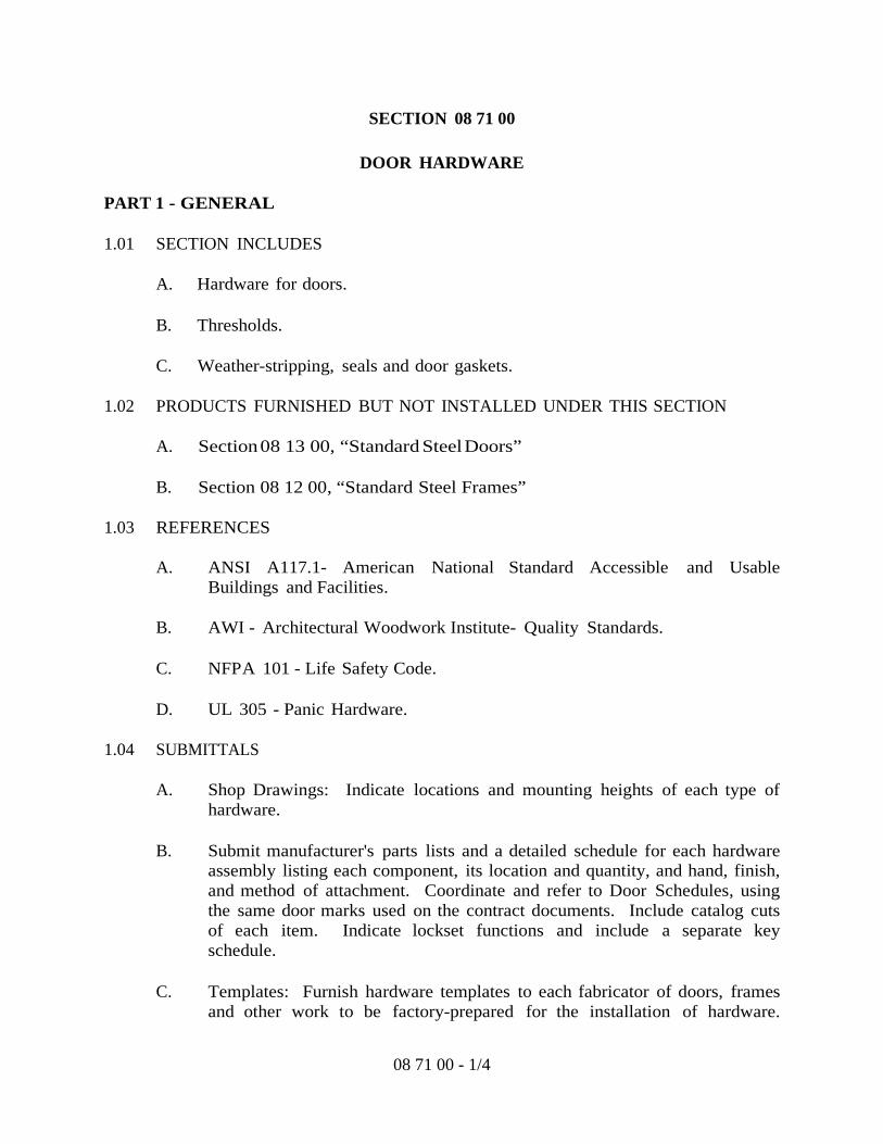
PART 1 - GENERAL 1.01 SECTION INCLUDES
A. Hardware for doors.
B. Thresholds.
C. Weather-stripping, seals and door gaskets. 1.02 PRODUCTS FURNISHED BUT NOT INSTALLED UNDER THIS SECTION
A. Section 08 13 00, “Standard Steel Doors”
B. Section 08 12 00, “Standard Steel Frames” 1.03 REFERENCES
A. ANSI A117.1- American National Standard Accessible and Usable Buildings and Facilities.
B. AWI - Architectural Woodwork Institute- Quality Standards.
C. NFPA 101 - Life Safety Code.
D. UL 305 - Panic Hardware.
1.04 SUBMITTALS
A. Shop Drawings: Indicate locations and mounting heights of each type of hardware.
B. Submit manufacturer's parts lists and a detailed schedule for each hardware
assembly listing each component, its location and quantity, and hand, finish, and method of attachment. Coordinate and refer to Door Schedules, using the same door marks used on the contract documents. Include catalog cuts of each item. Indicate lockset functions and include a separate key schedule.
C. Templates: Furnish hardware templates to each fabricator of doors, frames
and other work to be factory-prepared for the installation of hardware.
08 71 00 - 1/4

Upon request, check the shop drawing of such work to confirm that adequate provisions are made for the proper installation of hardware.
D. Manufacturer's Installation Instructions: Indicate special procedures,
perimeter conditions requiring special attention, and adjustment requirements for handicapped accessibility.
1.05 OPERATION AND MAINTENANCE DATA
Maintenance Data: Include data on operating hardware, lubrication requirements, and inspection procedures related to preventative maintenance.
1.06 QUALITY ASSURANCE
A. Perform work in accordance with the following requirements:
1. ANSI A 117.1 -2003 American National Standard Accessible and Usable Buildings and Facilities.
2. ANSI/BMHA
1.07 QUALIFICATIONS
A. Manufacturer: Company specializing in manufacturing the Products specified in this section with minimum three years documented experience.
B. Hardware Supplier: Company specializing in supplying institutional door
hardware with 3 years documented experience.
C. Hardware Supplier Personnel: Employ an Architectural Hardware Consultant (AHC) to assist in the work of this section.
1.08 DELIVERY, STORAGE, AND HANDLING
A. Deliver, store, protect and handle products to site.
B. Package hardware items individually; label and identify each package with door opening code to match hardware schedule.
C. Deliver keys to Owner by security shipment direct from hardware supplier.
1.09 COORDINATION
A. Coordinate the work with other directly affected sections involving manufacture or fabrication of internal reinforcement for door hardware.
08 71 00 - 2/4
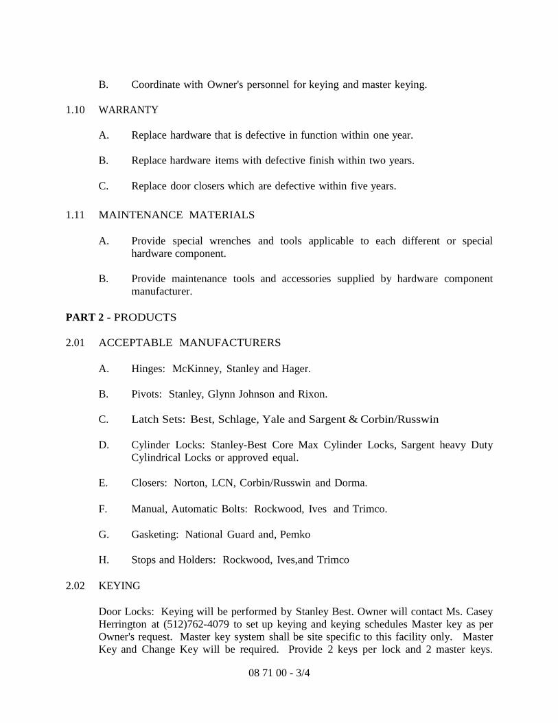
B. Coordinate with Owner's personnel for keying and master keying.
1.10 WARRANTY
A. Replace hardware that is defective in function within one year.
B. Replace hardware items with defective finish within two years.
C. Replace door closers which are defective within five years. 1.11 MAINTENANCE MATERIALS
A. Provide special wrenches and tools applicable to each different or special hardware component.
B. Provide maintenance tools and accessories supplied by hardware component
manufacturer. PART 2 - PRODUCTS 2.01 ACCEPTABLE MANUFACTURERS
A. Hinges: McKinney, Stanley and Hager.
B. Pivots: Stanley, Glynn Johnson and Rixon.
C. Latch Sets: Best, Schlage, Yale and Sargent & Corbin/Russwin
D. Cylinder Locks: Stanley-Best Core Max Cylinder Locks, Sargent heavy Duty Cylindrical Locks or approved equal.
E. Closers: Norton, LCN, Corbin/Russwin and Dorma.
F. Manual, Automatic Bolts: Rockwood, Ives and Trimco.
G. Gasketing: National Guard and, Pemko
H. Stops and Holders: Rockwood, Ives,and Trimco
2.02 KEYING
Door Locks: Keying will be performed by Stanley Best. Owner will contact Ms. Casey Herrington at (512)762-4079 to set up keying and keying schedules Master key as per Owner's request. Master key system shall be site specific to this facility only. Master Key and Change Key will be required. Provide 2 keys per lock and 2 master keys.
08 71 00 - 3/4

Construction and final cores to be provided by Contractor in accordance with Owner-provided final keying instructions.
2.03 FINISHES / SCHEDULES
Refer to Door Hardware Schedule on drawings for functions and finishes. All door hardware shall meet ADA requirements for physically disabled persons.
PART 3 - EXECUTION 3.01 EXAMINATION
Verify that doors and frames are ready to receive work and dimensions are as indicated on shop drawings.
3.02 INSTALLATION
A. Install hardware in accordance with manufacturer's instructions.
B. Use templates provided by hardware item manufacturer.
C. Mounting heights for hardware shall be as recommended in “Recommended Locations for Builders Hardware” by BHMA except as otherwise specifically indicated or required to comply with governing regulations.
3.03 FIELD QUALITY CONTROL
Architectural Hardware Consultant to inspect installation and certify that hardware and installation has been furnished and installed in accordance with manufacturer's instructions and as specified.
3.04 ADJUSTING
Adjust hardware for smooth operation. 3.05 PROTECTION OF FINISHED WORK
Do not permit adjacent work to damage hardware or finish.
Hardware Sets: Refer to drawings for hardware sets.
END OF SECTION
08 71 00 - 4/4

SECTION 08 80 00
GLAZING
PART 1 - GENERAL 1.01 SECTION INCLUDES
Glass and glazing for exterior & interior windows and doors. 1.02 RELATED SECTIONS
A. Section 07 92 10, “Joint Sealers”: Sealant and back-up material.
B. Section 05 51 13, “Aluminum Windows”.
C. Section 08 13 00, “Standard Steel Doors”. 1.03 REFERENCES
A. ANSI/ASTM E330 - Structural Performance of Exterior Windows, Curtain Walls, and Doors by Uniform Static Air Pressure Difference.
B. ANSI Z97.1 - Safety Performance Specifications and Methods of Test for Safety
Glazing Used in Buildings.
C. ASTM C1036 - Flat Glass.
D. ASTM C1048 - Heat-Treated Flat Glass- Kind HS, Kind FT Coated and Uncoated Glass.
E. ASTM E546 - Test Method for Frost Point of Sealed Insulating Glass Units.
F. ASTM E576 - Test Method for Dew/Frost Point of Sealed Insulating Glass
Units in Vertical Position.
G. ASTM E773 - Test Method for Seal Durability of Sealed Insulating Glass Units.
H. ASTM E774 - Sealed Insulating Glass Units.
I. FGMA - Glazing Manual.
J. FGMA - Sealant Manual.
K. FS TT-C-00598 - Caulking Compound, Oil and Resin Base Type.
08 80 00 - 1/5

L. FS TT-S-001657- Sealing Compound, Single Component, Butyl Rubber Based,
Solvent Release Type.
M. FS TT-S-00227- Sealing Compound, Rubber Base, Two Component.
N. FS TT-S-00230 - Sealing Compounds, Synthetic-Rubber Base, Single Component, Chemically Curing.
O. FS TT-S-01543 - Sealing Compound, Silicone Rubber Base.
P. FS TT-G-410 - Glazing Compound, Sash (Metal) for Back Bedding and Face
Glazing (Not for Channel or Stop Glazing).
Q. Laminators Safety Glass Association- Standards Manual.
R. SIGMA - Sealed Insulated Glass Manufacturers Association. 1.04 PERFORMANCE REQUIREMENTS
A. Size glass to withstand dead loads and positive and negative live loads acting normal to plane of glass as calculated in accordance with IBC 2009 to a design wind pressure of 120 mph.
B. Limit glass deflection to flexure limit of glass with full recovery of glazing
materials, whichever is less. 1.05 SUBMITTALS
A. Product Data on Glass Types Specified: Provide structural, physical and environmental characteristics, size limitations, special handling or installation requirements.
B. Product Data on Glazing Compounds: Provide chemical, functional, and
environmental characteristics, limitations, special application requirements. Color to be selected by Owner.
C. Manufacturer's Installation Instructions: Indicate special precautions required.
1.06 QUALITY ASSURANCE
Perform Work in accordance with FGMA Glazing Manual, FGMA Sealant Manual, SIGMA and Laminators Safety Glass Association - Standards Manual for glazing installation methods.
08 80 00 - 2/5

1.07 COORDINATION
Coordinate the Work with glazing frames, wall openings, and perimeter air and vapor seal to adjacent Work.
PART 2 - PRODUCTS 2.01 FLAT GLASS MATERIALS
Safety Glass@ Door Mark 111- Clear: Tempered glass or Laminated glazing with plastic interlayer; conforming to ANSI Z97.1; 1/4 inch thick minimum.
2.02 SEALED IMPACT RESISTANT INSULATING GLASS MATERIALS.
Laminated Insulated Impact Glass Units - Tinted @ all Exterior Windows: ASTM C1036 and C1172, as manufactured by Arch Aluminum & Glass Co., Inc./ Tru-Lite: consisting of outboard lite - outboard pane of ¼ " thick tinted (green) glass Low-E#2 color be verifies with Architect, inter layer of .100" Saflex HP (PVB) Low E by Solutia or Dupont, outboard lite-inboard pane of ¼'' thick clear heat strengthened glass, a sealed airspace of ½" , an inboard lite of ¼" thick, fully tempered clear glass for a total unit thickness of 1 5/16" to match the Kawneer framing system.
2.03 GLAZING COMPOUNDS
A. Modified Oil (Type GC-A): Non-hardening, knife grade consistency; gray color.
B. Butyl Sealant (Type GC-B): Single Component; Shore A hardness of 10-20 black color; non-skinning.
C. Acrylic Sealant (Type GC-C): Single Component, solvent curing, cured
Shore A hardness of 15-25; non-bleeding; color to match.
D. Polysulphide Sealant (Type GC-D): Two component, chemical curing, non-sagging type; cured Shore A hardness of 15- 25; color to match.
E. Polyurethane Sealant (Type GC-E): Single component, chemical curing,
non-staining, non-bleeding, non-sagging type, Shore A Hardness Range 20 to 35.
F. Silicone Sealant (Type GC-F): Single component; capable of water
immersion without loss of properties; non-bleeding non-staining; cured Shore A hardness of 15-25; color to match.
08 80 00 - 3/5

2.04 GLAZING ACCESSORIES
A. Setting Blocks: Neoprene or Silicone, per manufacturer's recommendations, 80 - 90 Shore A durometer hardness, length of 0.1 inch for each square foot of glazing or minimum 4 inch x width of glazing rabbet space minus 1/16 inch x height to suit glazing method and pane weight and area.
B. Spacer Shims: Neoprene or Silicone, per manufacturer's recommendations,
50- 60 Shore A durometer hardness, minimum 3 inch long x one half the height of the glazing stop x thickness to suit application.
C. Glazing Tape: Preformed butyl compound; 10- 15 Shore A durometer
hardness; coiled on release paper; black color.
D. Glazing Splines: Resilient extruded shape to suit glazing channel retaining slot.
E. Glazing Clips: Manufacturer's standard type.
PART 3 - EXECUTION 3.01 EXAMINATION
A. Verify that openings for glazing are correctly sized and within tolerance.
B. Verify that surfaces of glazing channels or recesses are clean, free of obstructions, and ready to receive glazing.
3.02 PREPARATION
A. Clean contact surfaces with solvent and wipe dry.
B. Seal porous glazing channels or recesses with substrate compatible primer or sealer.
3.03 EXTERIOR- DRY METHOD (PREFORMED GLAZING)
A. Cut glazing spline to length; install on glazing pane. Seal comers by butting spline and sealing junctions with butyl sealant.
B. Place setting blocks at 1/4 points with edge block no more than 6 inches from
comers.
C. Rest glazing on setting blocks and push against fixed stop with sufficient pressure to attain full contact.
08 80 00 - 4/5

D. Install removable stops without displacing glazing spline. Exert pressure for full continuous contact.
3.04 INTERIOR- DRY METHOD (TAPE AND TAPE)
A. Cut glazing tape to length and set against pem1anent stops, projecting 1/16 inch above sight line.
B. Place setting blocks at 1/4 points with edge block no more than 6 inches from
comers.
C. Rest glazing on setting blocks and push against tape for full contact at perimeter of pane or unit.
D. Place glazing tape on free perimeter of glazing in same manner described above.
E. Install removable stop without displacement of tape.
F. Exert pressure on tape for full continuous contact.
G. Knife trim protruding tape.
3.05 CLEANING
A. Remove glazing materials from finish surfaces.
B. Remove labels after work is complete. 3.06 SCHEDULE
As scheduled on Drawings.
END OF SECTION
08 80 00 - 5/5