Diversity Reception Helps Radio System Performance
9
Diversity reception controller helps radio system performance Part I-Short-term (multipath) fading can fluctuate received signals as much as SOdB. Without an adequate fade margin or other solutions, high- speed data communications can be adversely affected or entirely ruined. Figure 1. Long·term fading is caused primarily by distance and terrain. In general, as the distance between transmitter and receiver increases, the signal amplitude tends to decrease. Received signal levels tend to be stronger when the mobile receiver Is on hilltops with a line-of-sight radio path to the transmitter. Signals are weaker when the line-of-sight path is blocked by terrain. Figure 2. Short-term (multipath) fading is caused by a physical charac- teri stic of electromagnetic waves. A direct wave travels from the trans· mit antenna to the mobile receiver antenna. In addition, an incident wave strikes the ground close to the vehicle and reflects upward and into the receiver antenna. By Shane Fitzgerald The best criterion for evaluating radio system performance is the mobile user's ability to communicate successfully, de- fined as meeting or exceeding a standard of performance. A radio receiver's ability to meet a per- formance standard is a function of the re- ceived signal strength. If the received sig- ,.. nal is at or greater than the level required, successful communication is possible. If the received signal is less than the re- Fitzgerald is RF design engineer at ElectroCom Communications Systems. Santa Fe Springs, CA. ElectroCom manufactures lhe ideal selec- tion diversity controller described in this two- pa11 article. 52 Mobile Radio Tech11ology February 1995 quired level, successful communication is not possible. Short of equipment failure, there is only one reason for the received signal ampli- tude to fall below the required level: fad- ing. Fading is unquestionably the greatest cause of failed mob.ile radio communica- tions. Reducing the effects of fading leads to significant improvements in radio sys- tem performance. Two types of fading are present in the mobile radio environment, long-term fad- ing and short-term fading. Long-term fading is caused primarily by distance and terrain. In general, as the distance between transmitter and receiver increases, the signal amplitude tends to decrease. Received signal levels tend to be stronger when the mobile receiver is on hi ll tops with a line-of-sight radio path to the transmitter. Signals are weaker when the line-of-sight path is blocked by terrain. (See Figure I above .left.) Long-term fading has a gradual effect. As a receiver moves through a radio system's coverage area, the signal ampli- tude gradually moves up and down in re- sponse to distance and LOpography . The effects of Jong-term fading cannot be cor- rected at the mobile unit. Coverage defi- ciencies induced by long-term fading can be corrected only by changing the number or location of the radio sites, or by using on-frequency-repeater technology. Short-term (multipath) fading is caused by a physical characteristic of electro- magnetic waves. (See Figure 2 above right.) A direct wave travels from the transmit antenna to the mobile receiver antenna. In addition, an incident wave
-
Upload
anon849271 -
Category
Documents
-
view
216 -
download
1
description
.
Transcript of Diversity Reception Helps Radio System Performance

Diversity reception controller helps radio system performance
Part I-Short-term (multipath) fading can fluctuate received signals as much as SOdB. Without an adequate fade margin or other solutions, highspeed data communications can be adversely affected or entirely ruined.
Figure 1. Long·term fading is caused primarily by distance and terrain. In general, as the distance between transmitter and receiver increases, the signal amplitude tends to decrease. Received signal levels tend to be stronger when the mobile receiver Is on hilltops with a line-of-sight radio path to the transmitter. Signals are weaker when the line-of-sight path is blocked by terrain.
Figure 2. Short-term (multipath) fading is caused by a physical characteristic of electromagnetic waves. A direct wave travels from the trans· mit antenna to the mobile receiver antenna. In addition, an incident wave strikes the ground close to the vehicle and reflects upward and into the receiver antenna.
By Shane Fitzgerald
The best criterion for evaluating radio system performance is the mobile user's ability to communicate successfully, defined as meeting or exceeding a standard of performance.
A radio receiver's ability to meet a performance standard is a function of the received signal strength. If the received sig
,.. nal is at or greater than the level required, successful communication is possible. If the received signal is less than the re-
Fitzgerald is RF design engineer at ElectroCom Communications Systems. Santa Fe Springs , CA. ElectroCom manufactures lhe ideal selection diversity controller described in this twopa11 article.
52 Mobile Radio Tech11ology February 1995
quired level, successful communication is not possible.
Short of equipment failure, there is only one reason for the received signal amplitude to fall below the required level: fading. Fading is unquestionably the greatest cause of failed mob.ile radio communications. Reducing the effects of fading leads to significant improvements in radio system performance.
Two types of fading are present in the mobile radio environment, long-term fading and short-term fading.
Long-term fading is caused primarily by distance and terrain. In general, as the distance between transmitter and receiver increases, the signal amplitude tends to decrease. Received signal levels tend to be stronger when the mobile receiver is on hi ll tops with a line-of-sight radio path
to the transmitter. Signals are weaker when the line-of-sight path is blocked by terrain. (See Figure I above .left.)
Long-term fading has a gradual effect. As a receiver moves through a radio system's coverage area, the signal amplitude gradually moves up and down in response to distance and LOpography. The effects of Jong-term fading cannot be corrected at the mobile unit. Coverage deficiencies induced by long-term fading can be corrected only by changing the number or location of the radio sites, or by using on-frequency-repeater technology.
Short-term (multipath) fading is caused by a physical characteristic of electromagnetic waves. (See Figure 2 above right.) A direct wave travels from the transmit antenna to the mobile receiver antenna. In addition, an incident wave

t; w
~m w 'g a::z:W I-::> _ _, ~< -10-...1> Wen >2 ~a: - 20--....10 <I-~ -30--
iii
0.5 1.0 1.5
Figure 3. When a mobile receiver moves through an area, large fluctuations in received RF amplitude result. These fluctuations are periodic and occur at half-wavelength intervals (6.9 Inches at BSOMHz). The dynamic range of these flµctuatlons is about SOdB.
stri.kes the ground close to Lhe vehicle and reflects upward and into the receiver antenna. The power in the reflected wave
depends on the angle of inci dence (8) and the ground's reflection coefficient. For average soil, the reflec ted wave's magni-
tude exceeds 0.9 when e is less than 10° (which almost always is the case in land mobile communications). This small difference in magnitude means that the reflected wave's amplitude will be similar to the direct wave's amplitude. The mobile recei ver responds to two sources of radio energy, the direct wave from a distance and the reflected wave from the ground in close proximity to the receiver.
When an electromagnetic wave strikes a reflector, its phase shifts 180°, a phenomenon known as specular or mirrorimage reflection. These two waves, direct and reflected, interact to form a standing wave pattern of constructive and destructive interference.
Because it is impossible to see an electromagnetic standing wave pattern of constructive and destructive interference, it might be difficult to visualize. The water waves in a ripple tank demonstrate the phenomenon. (Sec Photo I on page 56).
In the ripple tank, two small floating balls (located at the center of the two circular patterns) are attached with strings to vertical osci llators on the bottom of the tank. As each ball osci llates up and down, it c reates waves. Waves from the two
csamee~-c::Jct-tnscn MCS-100 SERIES
MCS-100 SERIES
The Gamber-Johnson MCS· 100 Series is an economical alternative to consoles for mounting voice and data communications equipment in your Caprice or Crown Victoria.
Our base is one piece, made of 3/16" electrostallcally powdercoated steel. For safely, all edges are milled and corners rounded. Our design allows installation in minutes without drilling or modifying the vehicle. Our radio brackets are universal and simple to install and adjust. The 22 1/2" mounting surface gives you room for up to six sets of radio brackets, or a combination of brackets and a Gamber,Johnson MCS Series MDT or Laptop/Notebook mount. We even offer an adjustable armrest to assure an ergonomically correct work station.
The simplicity and strength of our design provides a margin of safety unsurpassed in the Industry, and ease of installation which saves you lime and money. Of course, the MCS-100 system is air bag friendly when properly Installed, and, ii desired, may be upgraded to an enclosed console protecting your initial investment years into the future.
Partial accessory sampling
For Information now ~ CALL 1-800-GJ·MOUNT 1-800-456·6868 ~ FAX 1-800-WE·HELPP 1-800·934-3577
csamae~-cJoHnson Service & Solutions ...
801 Francis Street. Stevens Poin t. Wisconsin 54481
Ctrcle (47) on Fast Fact Card
54 Mobile Radio 1'ecli110/ogy February 1995
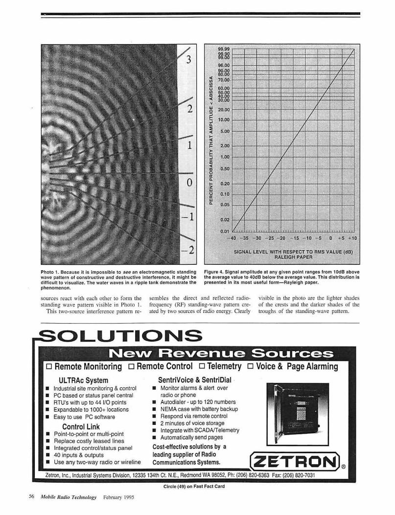
Photo 1. Because It is Impossible to see an electromagnetic standing wave pattern of constructive and destructive Interference, It might be difficult to visualize. The water waves In a ripple tank demonstrate the phenomenon.
ct Ill Ill (j ,Ill m < y w c E .... a. :I!: ct ... ct :c ... > !: .... iii < m 0 a: a. ... ~
0 a: w a.
~6.00
99.99
§3:88 II ' /
" I/
38:88 '10i00
60.00 50.00 '40.00 30.00
, 1, ' I 11 ..
"' I ~' . IA / .
, •" I•: •' '·
20.l>O
10.00
' " " I 1.~
I 5.QO
lo / 1 ••
I/ 2.00
1.00
' " I '
0.50 I
l/ 0.20
0.10
I
-17 .
0.05 I k
17 I•
0.02
0.01
I
v f
- 40 - 35 - 30 - 25 - 20 - 15 - 10 - s o +s + 10
SIGNAL LEVEL WITH RESPECT Te RMS VALUE (dB) RALEIGH PAPER
Figure 4. Signal amplitude at any given point ranges from 10dB above the average value to 40dB below the average value. This distribution Is presented in Its most useful form-Rayleigh paper.
sources react wi th each other tO form the standing wave pattern visible in Photo I.
This two-source interference panem re-
sembles the direct and reOe"c ted radiofrcquency (RF) standing-wave panem created by t\vo sources of radio energy. Clearly
visible in the photo are the lighter shades of the crests and the darker shades of the troughs of the standing-wave pattern.
o Voice & Page Alarming
t on, Inc., dust 'al Sys e s i ision, 1 335 th C . .E., e mo : (
Circle (49) on Fast Fact Card
56 Mobile RlU/io Technology February 1995

SS
The distance from maximum to minimum amplitude of the standing-wave pattern is one-half wavelength of the frequency of oscillation of the floating balls. Similarly, the distance from crest to crest or from trough to trough of short-term mobile radio fading is one-half wavelength of the radio waves' oscillation.
When a mobile receiver moves through an area, large fluctuations in received RF amplitude result. These fluctuations are periodic and occur at half-wavelength intervals (6.9 inches at 850MHz). The dynamic range of these fluctuations is about 50dB. Figure 3 on page 54 illustrates amplitude variations that a moving vehicle typically might encounter.
The distribution of shon-term fading is a function of two random variables and is the sum of coherent sinusoidal waves of random phase and random amplirude. This sum describes exactly the mobile radio short-term fading phenomenon, which sometimes is referred to as Rayleigh fading after Lord John William Strutt Rayleigh ( 1842-1919), a British physicist who first described the distribution.
Signal amplitude at any given point ranges from IOdB above the average value to 40d8 below the average value. This
distribution is presented in its most useful form-Rayleigh paper- in Figure 4 on page 56.
Rayleigh paper is an extremely useful tool for determining the percentage of probability that a signal will be above or below the average value. Numbers across the bottom of the graph represent signal amplitude (with respect to the average value) in decibels; therefore, 0 is the average value.
To find the percentage of probability of encountering a fade 20dB less than the average, foll ow the vertical -20dB line upward until it intersects with the diagonal line. Then read the graph directly to the left. In this example. there is a 1.0% probability of encountering a fade of 20dB.
Fade margin is an RF system design characteristic that indicates the system's ability to tolerate fades. It is expressed in decibels above the threshold where reliable communication takes place. As long as the average RF signal amplitude is 40dB above the level necessary for reliable communications- a figure that represents a 40dB fade margin-short-term fading will have no noticeable effect on the ability to communicate. Unfortunately, maintaining a 40dB fade margin in the field is practically impossible.
When a given geographic area's fade margin is 20dB. I % of the locations within the area will have RF amplitude below what is required for communication. If the fade margin is IOdB, then 10% of the locations will have RF amplitudes below that required for communications.
For voice communication via radio, fade margin can be translated directly into system reliability because shon-term fading effects on voice communication are more of a nuisance than a serious problem. The mind's processing power enables a listener to understand a voice message despite occasional noisy pops and hisses.
Short-term fading is extremely destructive to high-speed data communications. What the ear would endure as one little pop or a hissing sound may destroy several hundred bits of information. A mobile unit traveling at l 5mph through a stationary environment will encounter 38 fades per second, and more if the environment includes moving objects such as t:rains, aircraft aad automobiles. If these fades sink below the receiver's data recovery threshold, successful data reception becomes nearly impossible.
Next: How the i111egrity cf data conU1u111icatiom can be protected in a fading envir01U1iefll. ~
TwinPack®2 MAXIMIZES TELECOM POWER PCPs TwinPack2 is a compact power system ideal for telecom systems w ith limited space and high power requireme nts. Each TwinPack2 system consists of two modular, lightweight , switchmode rectifiers that plug into a total frontaccess mounting shelf. The modular rectifiers have input/output connectors for quick and easy installation and operation, and offer such
.. - .. . ----- - - --.;-;7:. ; ... ~ .,,, llC
advantages as N+ I redundancy, hot p lug-in, 0.98 power factor, 88% efficiency, and wide AC input voltage and frequency ranges for both domestic and foreign applications. Critical floor space is maximized by stacking mounting shelves directly on top of each other without the need of space or heat deflectors between shelves.
• Rectifier Module Ratings (22 lbs ea.) -48 Volt 50 Amp ±24 Volt I 00 Amp
• UL Listed • 8-3/4" H x 23" W x 15" D Shelf • Meets FCC EMI Standards • Meers Bellcore 11\.-NWl:OO 1089 and
TR-TSY-000947 • Meets IEC-555-2 • Passed Seismic Testing of Bellcore
TR-NWf-000063 and Pacific BelV Nevada Bell Seismic Publications.
For complete product literature, call or
fax us today!
(13 power conversion products inc. forty two east street p.o. box 380
crystal lake, illinois 60014 phone 1-800-447-3484 fax 1-800-526-2524
international phone 1-815-459-9100 international fax 1-815-459-9118
Circle (51) on Fast Fact Card
Mobile Rodio Tecl111otogy Fcbrnary 1995

Diversity reception controller helps radio system performance
Part 2-Using amplitude sensing, analog logic and output filtering along with low-cost integrated circuitry, an ideal selection diversity controller brings the
advantages of diversity reception to commercial mobile communications.
Figure 1. There are literally hundreds of variations on the concept of diversity reception. Most can be grouped Into two main classifications of diversity reception systems, mu/ti-antenna systems and multi-receiver systems, as shown above. Both of these schemes have proven largely unsuccessful, both technically and ~ommerclally, for a number of reasons.
By Shane Fitzgerald
Short-term (multipath) fadi ng, as described in the first installment of this twopart article, is extremely destructive to high-speed data communications. What the ear would endure as one little pop or a hissing sound may destroy several hundred bits of information. An 800MHz mobile unit traveling at 15mph through a stationary environment will encounter 38 fades per second, and more if the environment includes moving objects such as trains, aircraft and automobiles. If these fades sink below the receiver's data recovery threshold, successful data reception becomes nearly impossible.
How can the integrity of data communications be protected in a fading environment? Two of the most popular and widely used methods are fonvard error-correction
Fitzgerald is RF design engineer at ElectroCom Communications Systems, Santa Fe Springs, CA. ElectroCom manufactures the ideal selection diversity controller described in this twopart article.
36 Mobile Radio Technology March 1995
(FEC) and redundant transmissions. With FEC, message reconstruction in
fonnation is attached to each message prior to transmission. Should the message be received with errors, the reconstruction information is used to reconstruct the message. This method is complex. Me~sage rcconstruc1ion taxes the receiver's processing power because i1 is computationally intensive, and it reduces system throughput significantly because an FEC code is added to each transmission.
With redundant transmissions, each message is transmitted multiple times and a majority voting process is used to decode the message. This simple scheme is less computationally intensive than FEC; but multiple transmissions of identical information are extremely inefficient and dramatically reduce system throughput.
FEC and redundant transmissions share two fundamental flaws in dealing with the destructive interference caused by multipa1h fading. The first flaw these systems exhibit is their fa1alistic approach to the problem. Instead of trying to eliminate the source of the problem (short-tenn fading), these techniques try to recover from
the damage the fading causes. The other flaw is 1hat if the receiver remains stationary while in a deep fade, no amount of FEC or redundant transmissions will help; communication wi ll not be possible.
Diversity reception, on the other hand, reduces destructive effects of multipath fading directly. Two closely spaced antennas receive signals that are considered to be uncorrelated; therefore, when one antenna experiences a fade, then the probability of the 01her antenna simultaneously experiencing a fade is extremely unlikely. By selecting between antennas or receivers quickly enough and in response to the fades, the damaging effects of short-term fading are dramatically reduced.
There are literally hundreds of variations on the concept of diversity reception. Most can be grouped into two main classifications of diversiry reception systems, multi· antenna systems and multi-receiver systems, as shown in Figure 1 a1 the left. Both of these schemes have proven largely unsuccessful, both technically and commercially, for a number of reasons.
Multi-antenna diversity uses a single receiver with multiple antennas that are connected to it one al a time. When the receiver picks up an adequate signal from its current antenna, it maintains the connection. If the signal falls below a predetermined threshold, then the receiver swi1ches to another antenna that may deliver a better signal.
Unfortunately, there is no guaran1ee that a better signal will be found when the receiver switches antennas. The signal may, in fact, be worse. Moreover, waiting until the threshold of reliable communication is reached before switching means that a problem already has been encountered, rather than avoided.
Multi-receiver diversity uses multiple receivers to supply recovered modulation. Special circuitry de1ermines which

IFINPUT FBOMO
RECEIV.ER 2
DIVERSITY RECEPTION CONTROLLER
Figure 2. Tho diversity reception controller Includes three main soctlons: an amplitudo·sonsing section, an annlog logic section, and an output f ilter section.
receiver is receiving the better signal, and that receiver is then selected. Composite recovered modulation is assembled using a combination. or selection, algori thm. This process is technically complex. It has been largely unsuccessful because RF signal-level quantification circuitry cannol react fast enough to RF amplitude changes, and in the selection algorithm. high-speed switching between discontinuous signals causes damaging uansientS.
·Fortunately. advances in performance along with reductions in the cost of integrated circuitry have enabled the development of a low-cost, highly efficient diversity reception controller that overcomes previous multi-antenna and multi-receiver problems. The controller's ideal selection diversity uses multiple receiver outputs that arc selected by comparing RF carrier amplitudes.
Figure 2 above is a block diagram of the
The value of any paging sy~tem "depencts· : upon the quality of Its support. 'Fhat's why our Model 640 and 2000 Serles paging terminals have the best technical support possible: 24 hours a day, 365 aays a year.
diversity reception controller, which includes three main sections: an am1>lil11dcsensing section, an analog logic section. and an output filter section.
The amplitude-sensing section contains high-speed, integrated, intermediatefrequency (IF) processors that provide rF amplitude infonnation proportional to the received signal at each antenna. ·nie processors generate an ultra-fast de voltage received signal strength indicator (RSSI) proportional to the Jog of received power in decibels over a wide dynamic range.
The analog logic section processes the lF amplitude voltage, receives recovered modulation from the receivers and continuously selects recovered modulation from the receiver with the higher relative received signal.
The output filter section removes transients caused by high-speed switching between two discontinuous signals while ensuring constant input-to-output delays and fast settling characteristics. The fi lter can be programmed to accommodate a ll common Ir bandwidths and response characteristics.
Also included is a power supply designed specifically fo r automotive applications.
. .. Since everiy erminal has a built-ii) modem for remgtE!j
access, our application engineers·cao fine-tune your system any time you want. All by modem, on demand.
Our ongoing development program, diverse procfl.ict line, and industry success guarantee that you can count on our support tor the lifetime of your operation.
And our support starts now. We'll help you configure the terminal to meet your needs today and tomorrow.
Model 640 and Serles 2000 Paging Terminals • up to 50,000 subscribers, 36 telco trunks, 8 radio channels, 72 tirs voice storage
We'll Always Be Here For You 12335 1341het. N.e. (ZETRON) ... Redmond WA 98052 · • ""
Circle (34) on Fast Fact Card
38 Mobile Radio Tec/1110/Qgy March 1995

~~s •_o_p_p~eu_: _ ... __ /,~~;.~~ '.' '.s.~~~~': __ -·-~· ._i ~--.,.-.. J .... ,-r-···-······.,·-····-. ,.------=... t\: I 0 ttz Cf12
Photo 1 at the left and Photo 2 on page 42 are plots taken from a digital storage osci lloscope connected to a diversity reception controller. 111ese plots demonstrate short-term fade reduction that an ideal selection diversity system provides. ··;···
?
I !.
. I I
. . I
\!.ti: 6 m Bandwidth
I I
"T
Position Offset ···3.0if div a v
il .L .. J . Full
.l~. 100 MHZ
C1l l'rolle t11ieializetl
Ch I (the upper trace) is the receivers' RSSI signal selected by the diversity reception controller to supply recovered modulation. Ch2 (the lower trace) displays the RSSI signals of the individual receivers. The diversity reception controller always selects the receiver with the higher relative signal level. This plot was taken in a vehicle traveling about IOmph. The plot is a 500ms snapshot of the short-term fading typically encountered in the mobile environment.
Voltages displayed on the oscilloscope plots correspond to the received signal amplitude as follows:
8.0V -90d8m 6.0V - lOOdBm 4.0V -1 IOdBm 2.0V - 120dBm 0.0V - 130dl3m
Photo 1. This digital storage oscllloscope display demonstrates the short-term fade reduction that an ideal selection diversity system provides during 500ms of reception In a vehicle traveling ot 10mph. The lowest received signal strength encountered by tho selected receivers was about -105dBm. Unselected receivers encountered numerous fades, six of which dipped to -130dBm.
As shown in Photo I , the lowest received signal strength encountered by the selected receivers was about -105dBm.
Ou'lL FilND o ~Eff Hutton's 1995 Product Selection Guide is ?esi_gned for the. busy mobile
Bo G1l£~T B'.RAM1Jsco~~~00~a~~;~if;~t:~s;onal .
• so+ select manufacturers Never hunt through a huge stack
UN1J'Ell 1JHf C'O~Ell ~!~~~~~o:~u~gfr;~ ~~~;~ft~l~:~~~·~o 1995 Product Select~on Guide today. You'll be glad you dtd!
40 Mobile Radio Tec/11111/Qgy March 1995
Dallas.Texas 800-442-3811
Atlanta.Georgia 800-741-38 11
Denver, Colorado 80(). 726-6245
Seattle,Washington 800-426-2964
Toronto, Canada 800.265-8685
Mexico (9 5) 8()().86&-3811 I
'95 HUTTON CATALOG IS HERE! I Circle (36) on Fast Fact Card

'
Tel< stopped: 4 Acquisitions
Unselected receivers encountt:red numerous fades, six of which dipped to - 130dBm.
T -·· -·- -'--.----- ·_} ------.. ·---ChZ
nandwldth
Photo 2 i s another SOOms snapshot of typical short-term fading. iaken at a slightly slower speed. Clearly evident is the classic shape of a Rayleigh distribution. ·f a: 10 Hz
@: GHZ
Cl Full
Cal Probe lnilioflzed
This diversi ty reception method's gain is proponional to the fade depth. For example, the percentage or probability of encountering a - I OdB fade with ideal selection diversity reception is 1.0%, onetenth or the percentage or probability without d iversity . The percentage of probability of encountering a fade of -20c!B with ideal selection diversity reception is 0.01 %, one-hundredth of the percentage of probability without di versity.
Figure 3 on page 44 depicts this increa~e in fade protection. The left side of the graph indicates the percentage of probabi lity of cncoumcring a fade without diversity reception. The right side indicates the percentage of probability with a diversity reception controller.
Photo 2. Another SOOms snapshot of typical short-term fading, taken at a slightly slower speed. Clearly evident Is tho classic shape of a Raylolgh distribution .
The increase in performance provided by the diversity controller translates into system reliability. As seen in Figure 3, 99% reliability can be achieved with only a 1 Odl3 fade margin. representing a IOdB
. caameer-1-c:Jct-tnscn MCS-100 SERIES
The Gamber-Johnson MCS-100 Series is an economical al ternative to consoles for mounting voice and data communications equipment in your Caprice or Crown Victoria.
Our base is one piece, made of 3/16" electrostatically powdercoated steel. For safety, all edges are milled and corners rounded. Our design allows installation In minutes without drilling or modifying the vehicle. Our radio brackets are universal and simple to install and adjust. The 22 1/2" mounting surface gives you room tor up to six sets of radio brackets, or a combination of brackets and a Gamber-Johnson MCS Series MDT or Laptop/Notebook mount. We even otter an adjustable armrest to assure an ergonomically correct work station.
The simplicity and strength of our design provides a margin of safety unsurpassed in the industry, and ease of installation which saves you time and money. 0 1 course, the MCS-100 system is air bag friendly when properly installed, and, if desired, may be upgraded to an enclosed console protecting your initial investment years into the future.
Partial accessory sampling
MCS-100 SERIES
For Information now ~ CALL 1·800-GJ·MOUNT 1·800-456·6868 ID FAX 1-000-we-HELPP 1-eoo-934.3sn
same e~ -cJc:n-Hison Service & Solutions ...
801 F ranc1s Street. Stevens Point. Wisconsin 54481
Circle (38) on Fast Fact Card
42 Mobile Rodio Tecltnology March 1995

WAR Call Ray Dashner today
at 800-545-1349 for blowout Tone Panel
'() pricing!
.-----... - - ·=- - --1 .....,L....,.~=-· •. _ ___J
0 H ere are some of the reasons our TP-154 is your best choice ...
• Lowest Price. ~ • 50 CTCSS Tones.
• 104 DCS Codes.
• Front Panel Display.
• CTCSSTRACK"' gives best sensitivity.
• Unbeatable performance.
• More programability than any other panel.
Andmore! ¢ IMMEDIATE DELIVERY ONE YEAR WARRANTY
Made in U.S.A. Sale subject to withdraw/ and only available in U.S.~
I ?'"--""i ?co:NECT svsnus INC.
Zl.s9 Po11<>la Rd Vrnrun, Ca q.loos ~ l'lloDo {30~) 64Z·11"4 Fu t80.)) 64~ 12'1 V
Toll r~c 800-545-1349 CSI Is a rogls101ed irademark ol Connocl Sys1oms Inc.
Clrclo (40) on Fast Fact Card
44 Mobilt Radio Ttchna/Qgy March 1995
99.99
3§:88 '96.00 90.00 80.00 70.00
J , IJ I ~ . ! (
•: i.- II 1: ill I~ 1;. '; -~ '" ' " 1·-· /
I 60.00
< 50.00 Ul 40.00 Ul 0 30.00 Ul m 20.00 < v
w 10.00 0 :>
5 5.00 0.. :IE < !;( 2.00
i: ~
1.00
::J iD 0.50 < m 0 a:
0.20 0..
~ w 0.10 0 a: w 0.05 II..
/ , , I
,. · .. ,,
J , I• I• tr./ . '
'-
I I - I • 1 I•
' • ,. J
' 1,/ ~ ,,
I I I J
";; ..
I HI - ~
v I ;
"O m ~ ::D - o ~m z 6~ m -o
1.0 ~q~ ~~ 0 !a-m !:'. :D ,.f J> '<: z.:.f o-:£: z J> tn -I
0.1 m"> ,.. :: m "O
gs oc zc cm - h · <> mm :D Q)..
!!? 0 ::;! in
(/)
0.0001 >
0.02
0.01
J
I/ { . .. . • - 40 - 35 - 30 - 25 - 20 - 15 -10 -5 0 +5 +10
SIGNAL LEVEL WITH RESPECT TO RMS VALUE (dB) RALEIGH PAPER
Figure 3. The Increase In fade protection for Ideal selection diversity reception Is proportional to the depth of fades encountered. The left side of the graph Indicates the percentage of probability of encountering a fade without diversity reception. The ri ght side indicates tho percentage of probablllty with a diversity reception controller.
improvement over a system wi thout diversity reception. A 99.9% reliabili ty can be achieved with a 20dB fade margin; this represents a 20dB improvement over a system without diversity reception.
Adding diversi ty reception lo an exist· ing radio communi cations system increases its coverage area and incre<L~es its reliability \\ithin any given area. For data communications systems. the success rate of first-attempt delivery of dma messages rises dramatically, regardless of vehicle speed.
For voice communication. the diversity reception controller provides an 8dB- IOdB improvement in signal-to-noise ratio (SIN).
The diversity reception comroller can retrofit existing radio systems with the performance advantage of ideal selection diversity reception. An entire fleet can undergo retrofit , or only specific vehicles (such as vehicles that frequent poor coverage areas).
Although the focus of this article has been mainly on the mobile receiver. the
base receiver or repeater receiver is subject to the same short-tenn fading effects as the mobile unit. In tenns of performance vs. cost, equipping the system base or re· peater station with diversity reception yields the most performance per dollar because the advantages of diversity reception are shared by all users.
A dramatic increa~e in performance of mobile-to-mobile communications is possible when both repeater and mobile recei vcrs are equipped with the diversity reception controller. The uplink's recovered audio experiences an 8dB- 10dB increase in SIN performance. This betterquality audio is repealed on the downlink to a diversity-equipped mobile receiver with an 8dB- 10dB increase in SIN performance. The aggregate SIN performance increase can be as high as J 6dB to 20dB.
The controller is easy 10 install with few connections required and is compatible with all existing communjcations rec..:ivers. ~