
Disturbance Attenuation in a Magnetic Levitation System ...
12
Marquee University e-Publications@Marquee Mechanical Engineering Faculty Research and Publications Mechanical Engineering, Department of 3-14-2011 Disturbance Aenuation in a Magnetic Levitation System with Acceleration Feedback Feng Tian Marquee University Craig Kevin Marquee University Mark L. Nagurka Marquee University, [email protected] Accepted version. Published as a part of 2011 IEEE International Conference on Industrial Technology, (March 14-18, 2011). DOI. © 2011 IEEE. Used with permission.
Transcript of Disturbance Attenuation in a Magnetic Levitation System ...

Marquette Universitye-Publications@MarquetteMechanical Engineering Faculty Research andPublications Mechanical Engineering, Department of
3-14-2011
Disturbance Attenuation in a Magnetic LevitationSystem with Acceleration FeedbackFeng TianMarquette University
Craig KevinMarquette University
Mark L. NagurkaMarquette University, [email protected]
Accepted version. Published as a part of 2011 IEEE International Conference on IndustrialTechnology, (March 14-18, 2011). DOI. © 2011 IEEE. Used with permission.

Marquette University
e-Publications@Marquette
Mechanical Engineering Faculty Research and Publications/College of Engineering
This paper is NOT THE PUBLISHED VERSION; but the author’s final, peer-reviewed manuscript. The published version may be accessed by following the link in the citation below.
2011 IEEE International Conference on Industrial Technology, (2011): 59-64. DOI. This article is © IEEE and permission has been granted for this version to appear in e-Publications@Marquette. IEEE does not grant permission for this article to be further copied/distributed or hosted elsewhere without the express permission from IEEE.
Disturbance attenuation in a magnetic levitation system with acceleration feedback Feng Tian Department of Mechanical Engineering, Marquette University, Milwaukee, WI 53233 USA Kevin Craig Department of Mechanical Engineering, Marquette University, Milwaukee, WI 53233 USA Mark Nagurka Department of Mechanical Engineering, Marquette University, Milwaukee, WI 53233 USA
ABSTRACT The objective of this work is to demonstrate the use of acceleration feedback to improve the performance of a maglev system, especially in disturbance attenuation. In the single degree-of-freedom (DOF) system studied here, acceleration feedback has the effect of virtually increasing inertia, damping and stiffness. It is shown that it can be used to increase disturbance rejection without sacrificing tracking performance. Both analytical and experimental results demonstrate that disturbance rejection can be improved with acceleration feedback.
SECTION I. INTRODUCTION Magnetic levitation (or maglev) systems utilize electromagnetic forces to achieve levitation. They are open-loop unstable and inherently nonlinear. Feedback control loops are used to manipulate the electromagnetic forces to

counterbalance gravity. Examples of maglev technology can be found in frictionless bearings, vibration isolation equipment, and maglev vehicles. A classic control design approach for a maglev system is to linearize the nonlinear system dynamics about an operating point (equilibrium point) and design a linear controller that operates about that point. Although the system is designed to work at the operating point or its vicinity, disturbances may drive the system away from the operating point. If the disturbances are too large, the system will lose balance and fail to operate. Research work has been carried out to find how to attenuate disturbances and improve the performance of maglev systems. Investigators have proposed different control strategies. Shan and Menq [1] reported two disturbance rejection algorithms-internal model-based control and sliding mode control-that improved the dynamic stiffness of a magnetic suspension stage. Both simulation and experiments indicated that the dynamic stiffness of their system was increased. Fang, Feemster and Dawson [2] reported a position regulation control strategy developed for a magnetic levitation system operating in the presence of a bounded, nonlinear, periodic disturbance. They included simulation results, but no experimental data was reported. Another position regulation control strategy, reported by the same authors in 2006 [3], required that the disturbance be bounded and the period of the disturbance be known. She, Xin and Yamaura [4] described a technique called equivalent-input-disturbance estimation. The controller, designed using H∞ control theory, generated an input signal based on the information from a state observer. The input signal cancelled the effect of the real disturbance. They provided simulation results without experimental verification. Previous research efforts show that different control strategies can be used to increase the overall performance of a maglev system. This research investigates an approach that improves disturbance attenuation while not changing the system response to a reference signal. Acceleration feedback has been studied by previous researchers and proved to be effective in improving system performance in disturbance rejection. However, prior work has not discussed the implementation of acceleration feedback on maglev systems. The primary goal of this paper is to show that acceleration feedback can be used on a maglev system to attenuate disturbance. Both analytical and experimental evaluations of the acceleration feedback technique are presented. The acceleration control type servo system was proposed as a novel design paradigm of servo systems by Hori [5], and was further developed as a hybrid control method for the position and mechanical impedance of robot actuators [6]. Experiments demonstrated the effectiveness of both systems in disturbance suppression. Acceleration feedback control has also been reported and used to improve the performance of DC drives [7]. It allows systems to achieve substantially higher overall stiffness without requiring higher bandwidths of the velocity and position loops. For a maglev system, it is important to note that acceleration feedback control alone does not guarantee stability. For that, the system needs a position regulator. The acceleration feedback changes the effective inertia, damping, and stiffness of the system. It increases the effective inertia of the system for disturbance rejection purposes. The maglev system used in this research is stabilized with a PD controller. The system serves as a baseline from which to make performance comparisons. Comparisons are made between the system responses with and without an acceleration feedback loop to a sinusoidal position command, first as a position reference signal 𝑅𝑅 and then as a disturbance signal D, as is shown in Fig. 1. Performance is evaluated based on the magnitude ratio (in dB) of the output versus input signals.

Fig. 1. Block diagram of a system subject to disturbance D
In the following sections, the plant model of the maglev system is presented and the basic theory of acceleration feedback is introduced. The design, analysis, and simulation of the acceleration feedback controller are shown. Experimental results demonstrate the advantage of improved performance with acceleration feedback on the maglev system.
SECTION II. MAGLEV PLANT AND POSITION REGULATOR Fig. 2 shows a free body diagram of a single degree-of-freedom (DOF) maglev device. Woodson and Melcher [8] proved that the attractive force acting on the ferrous object is approximated by
𝐹𝐹(𝑖𝑖, 𝑥𝑥) ≅ 𝐾𝐾1 �𝑖𝑖
𝐾𝐾2+𝑥𝑥�2
(1)
where 𝐾𝐾1 and 𝐾𝐾2 are parameters characterized by the geometry and construction of the electromagnet. These parameters are determined experimentally in this research. Equation (1) can also be derived from Maxwell's equations. One important assumption is that the ferrous object stays at the vicinity of the electromagnet so the magnetic fringe flux can be neglected.
Fig. 2. Free body diagram of the maglev system
The governing equation for the ferrous object is determined using Newton's second law. Assuming vertical motion only, a force balance on the levitated object shown in Fig. 2 yields

𝑚𝑚𝑥𝑥¨
= 𝑚𝑚𝑚𝑚 − 𝐾𝐾1 �𝑖𝑖
𝐾𝐾2+𝑥𝑥�2
(2)
Equation (2) shows the nonlinear form of the plant. In order to design a linear controller for the system, a linearized model is derived at the operating point where i=i0,x=x0, and x˙=0. The Taylor series of equation (2) is
𝑚𝑚𝑥𝑥¨
= 𝑚𝑚𝑚𝑚 − 𝐾𝐾1 �𝑖𝑖0
𝐾𝐾2+𝑥𝑥0�2
+ 𝐾𝐾1 �2𝑖𝑖02
(𝐾𝐾2+𝑥𝑥0)3� 𝛿𝛿𝑥𝑥
−𝐾𝐾1 �2𝑖𝑖0
(𝐾𝐾2+𝑥𝑥0)2� 𝛿𝛿𝑖𝑖
(3)
At the operating point the system reaches equilibrium,
𝑚𝑚𝑚𝑚 = 𝐾𝐾1 �𝑖𝑖0
𝐾𝐾2+𝑥𝑥0�2
(4)
Substituting equation (4) into equation (3),
𝑚𝑚𝑥𝑥¨
= 𝐾𝐾1 �2𝑖𝑖02
(𝐾𝐾2+𝑥𝑥0)3� 𝛿𝛿𝑥𝑥 − 𝐾𝐾1 �
2𝑖𝑖0(𝐾𝐾2+𝑥𝑥0)2
� 𝛿𝛿𝑖𝑖 (5)
where 𝑥𝑥 = 𝑥𝑥0 + 𝛿𝛿𝑥𝑥 and 𝑖𝑖 = 𝑖𝑖0 + 𝛿𝛿𝑖𝑖. Letting
𝑘𝑘𝑥𝑥 = 𝐾𝐾1𝑚𝑚� 2𝑖𝑖02
(𝐾𝐾2+𝑥𝑥0)3� (6)
and
𝑘𝑘𝑖𝑖 = 𝐾𝐾1𝑚𝑚� 2𝑖𝑖0
(𝐾𝐾2+𝑥𝑥0)2� (7)
the equation of motion for the magnetic system is
𝑥𝑥¨
= 𝑘𝑘𝑥𝑥𝛿𝛿𝑥𝑥 − 𝑘𝑘𝑖𝑖𝛿𝛿𝑖𝑖 (8)
Equation (8) is the linearized governing equation for the maglev system where the current 𝛿𝛿𝑖𝑖 is controlled. Fig. 3 shows the block diagram of the open-loop system where 𝑋𝑋(𝑠𝑠) is the Laplace transform of 𝛿𝛿𝑥𝑥 and 𝐼𝐼(𝑠𝑠) is the Laplace transform of 𝛿𝛿𝑖𝑖.

Fig. 3. Block diagram of the open-loop system without acceleration feedback Taking the Laplace transform of both sides of equation (8) and assuming zero initial conditions,
𝑠𝑠2𝑋𝑋(𝑠𝑠) = 𝑘𝑘𝑥𝑥𝑋𝑋(𝑠𝑠) − 𝑘𝑘𝑖𝑖𝐼𝐼(𝑠𝑠) (9) Rearranging, the open-loop transfer function of the system is
𝑋𝑋(𝑠𝑠)𝐼𝐼(𝑠𝑠)
= −𝑘𝑘𝑖𝑖𝑠𝑠2−𝑘𝑘𝑥𝑥
(10)
where the input is the control current and the output is the levitated object position. From equation (10) the system has a pair of real poles at ±�𝑘𝑘𝑥𝑥. The plant is open-loop unstable due to the positive real pole. A position regulator is needed to achieve stable levitation. In this research, a PD controller is used. If the levitated object moves away from the desired operating point, the controller will adjust the current passing through the electromagnet to provide a restoring force to attenuate the position error. From the control perspective, this is similar to adding “stiffness” by using the gains of the controller. Fig. 4 shows the block diagram of such a position feedback controller in a cascaded configuration.
Fig. 4. Maglev system with a PD controller For such a system, the stiffness is provided solely by the controller. It is sometimes referred to as the “active stiffness.” (Active stiffness is added by the stiffness terms resulting from the controller gains.) Fig. 5 shows the block diagram of such a system with a disturbance D.
Fig. 5. System without acceleration feedback loop with disturbance 𝐷𝐷
The transfer function between the disturbance 𝐷𝐷 and the output position 𝑋𝑋 for this system is
𝑋𝑋(𝑠𝑠)𝐷𝐷(𝑠𝑠)
= −𝑘𝑘𝑖𝑖𝑠𝑠2+𝑘𝑘𝑖𝑖𝐾𝐾𝑑𝑑𝑠𝑠+𝑘𝑘𝑖𝑖𝐾𝐾𝑝𝑝−𝑘𝑘𝑥𝑥
(11)
From equation (11), it is obvious that the frequency response is shaped by the active controller gain 𝐾𝐾𝑑𝑑 and 𝐾𝐾𝑝𝑝. The position regulator is actively used to achieve a stable levitation as well as reduce the response of the system to disturbances. In order to increase the stiffness of the system, a larger controller gain is needed. Fig. 6 shows the Bode plot of two system with different P gains and 𝐷𝐷 gains. From the plot we can see higher controller gains

help to attenuate the system response to the disturbance. However, for a maglev system, increasing the controller gain may cause the system to be unstable. The conclusion is that in order to increase the stiffness, the controller gains need to be increased, but only certain gain values will maintain the stability of the system. To raise the dynamic stiffness without changing the controller gains requires the use of acceleration feedback.
Fig. 6. Bode diagram of a maglev system with different controller gains
SECTION III. ACCELERATION FEEDBACK PRINCIPLE Schmidt and Lorenz [7] demonstrated the principle, design, and implementation of acceleration feedback control to improve the performance of DC servo drives. In their research, the acceleration signal was estimated using an acceleration observer, scaled by a factor 𝑘𝑘𝐴𝐴𝐴𝐴𝐴𝐴 and fed back to the controller. The feedback loop adds “electronic” inertia to the system. In this research, the acceleration signal is calculated using equation (8) instead of measuring it with an accelerometer. Fig. 7 shows a block diagram of a maglev system with acceleration feedback assuming the acceleration signal is available. The acceleration calculation and acceleration feedback implementation will be given in the Experimental Results section. The acceleration feedback loop is closed by a positive feedback instead of a negative one because there is a negative sign in the open-loop transfer function of the plant, as is shown in equation (10).
Fig. 7. Block diagram of the open-loop system with acceleration feedback With the acceleration feedback loop, the current error signal 𝑒𝑒 become

𝑒𝑒 = 𝛿𝛿𝑖𝑖 + 𝑘𝑘𝐴𝐴𝐴𝐴𝐴𝐴𝑥𝑥¨ (12)
The acceleration signal 𝑥𝑥¨ becomes
𝑥𝑥¨
= −𝑘𝑘𝑖𝑖𝑒𝑒 + 𝑘𝑘𝑥𝑥𝛿𝛿𝑥𝑥 (14)
Substituting equation (13) into equation (12), the acceleration signal can be written as
𝑥𝑥¨
= −𝑘𝑘𝑖𝑖(𝛿𝛿𝑖𝑖 + 𝑘𝑘𝐴𝐴𝐴𝐴𝐴𝐴𝑥𝑥¨) + 𝑘𝑘𝑥𝑥𝛿𝛿𝑥𝑥 (13)
Take the Laplace transform of both sides of equation (14) and rearranging, the open-loop transfer function of the maglev system with an acceleration feedback loop is
𝑋𝑋(𝑠𝑠)𝐼𝐼(𝑠𝑠)
= −𝑘𝑘𝑖𝑖(1+𝑘𝑘𝑖𝑖𝑘𝑘𝐴𝐴𝐴𝐴𝐴𝐴)𝑠𝑠2−𝑘𝑘𝑥𝑥
(15)
where the input is the control current and the output is the gap distance. To ensure the transfer function between the reference single 𝑅𝑅 and output 𝑋𝑋 remains the same, the PD position control gains must be scaled by a factor of (1 + 𝑘𝑘𝑖𝑖𝑘𝑘𝐴𝐴𝐴𝐴𝐴𝐴). The closed loop system with both a PD controller and an acceleration feedback loop is shown in Fig. 8.
Fig. 8. System with a PD controller and an acceleration feedback loop The transfer function between the disturbance 𝐷𝐷 and the displacement 𝑋𝑋 is
𝑋𝑋(𝑠𝑠)𝐷𝐷(𝑠𝑠)
= −𝑘𝑘𝑖𝑖/[(1 + 𝑘𝑘𝑖𝑖𝑘𝑘𝐴𝐴𝐴𝐴𝐴𝐴)𝑠𝑠2 + 𝑘𝑘𝑖𝑖(1 + 𝑘𝑘𝑖𝑖𝑘𝑘𝐴𝐴𝐴𝐴𝐴𝐴)𝐾𝐾𝑑𝑑𝑠𝑠
+𝑘𝑘𝑖𝑖(1 + 𝑘𝑘𝑖𝑖𝑘𝑘𝐴𝐴𝐴𝐴𝐴𝐴)𝐾𝐾𝑝𝑝 − 𝑘𝑘𝑥𝑥] (16)
The effect of adding acceleration feedback is the same as adding some inertia-the so-called “electronic” inertia. The “electronic” inertia makes the disturbance seem like it is acting on a larger mass. The resulting effect on the dynamic stiffness is shown in Fig. 9. (The phase shift does not change and is thus omitted here.)

Fig. 9. System responses of systems with and without acceleration feedback With acceleration feedback the dynamic magnitude response curve shifts down, which means the stiffness of the system has increased. The concept can be understood better by taking a look at the dynamic stiffness change of the system, which is the inverse of the transfer function between the disturbance and the system output. For a system without acceleration feedback, the dynamic stiffness is
𝐷𝐷(𝑠𝑠)𝑋𝑋(𝑠𝑠)
= 𝑠𝑠2+𝑘𝑘𝑖𝑖𝐾𝐾𝑑𝑑𝑠𝑠+𝑘𝑘𝑖𝑖𝐾𝐾𝑝𝑝−𝑘𝑘𝑥𝑥−𝑘𝑘𝑖𝑖
(17)
For a system with acceleration feedback, the dynamic stiffness is
𝐷𝐷(𝑠𝑠)𝑋𝑋(𝑠𝑠)
= [(1 + 𝑘𝑘𝑖𝑖𝑘𝑘𝐴𝐴𝐴𝐴𝐴𝐴)𝑠𝑠2 + 𝑘𝑘𝑖𝑖(1 + 𝑘𝑘𝑖𝑖𝑘𝑘𝐴𝐴𝐴𝐴𝐴𝐴)𝐾𝐾𝑑𝑑𝑠𝑠
+𝑘𝑘𝑖𝑖(1 + 𝑘𝑘𝑖𝑖𝑘𝑘𝐴𝐴𝐴𝐴𝐴𝐴)𝐾𝐾𝑝𝑝 − 𝑘𝑘𝑥𝑥]/(−𝑘𝑘𝑖𝑖) (18)
The denominators of equations (17) and (18) are the same and the numerators are the characteristic equations of the systems. By choosing an appropriate acceleration feedback gain 𝑘𝑘𝐴𝐴𝐴𝐴𝐴𝐴, the gains for the double derivative term, derivative term, and constant term can be made larger in equation (18) than those in equation (17). The factor ‘‘1 + 𝑘𝑘𝐴𝐴𝐴𝐴𝐴𝐴
′′ makes the mass seem to be ‘‘𝑘𝑘𝐴𝐴𝐴𝐴𝐴𝐴′′ times more than its real value. This additional part is the
so-called “electronic” inertia added to the system. In addition, the “electronic” damping coefficient 𝑘𝑘𝑖𝑖𝐾𝐾𝑑𝑑 is increased by ‘‘𝑘𝑘𝑖𝑖𝑘𝑘𝐴𝐴𝐴𝐴𝐴𝐴
′′ times. The equivalent stiffness is also increased. It means more “effort” in disturbance 𝐷𝐷 is needed to achieve the same 𝑋𝑋. In other words, a system with acceleration feedback will have less change when experiencing the same disturbance as a system without acceleration feedback. Introducing an acceleration feedback loop has the effect of increasing the effective mass, damping, and stiffness of the system. Experiments will show that the system response to the reference signal remains unchanged.
SECTION IV. EXPERIMENTAL RESULTS For the maglev system discussed here, the position signal is available for measurement and the control current, which is the output of the controller, is assumed known. Equation (8) gives the expression of the acceleration
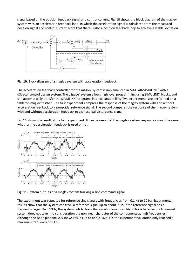
signal based on the position feedback signal and control current. Fig. 10 shows the block diagram of the maglev system with an acceleration feedback loop, in which the acceleration signal is calculated from the measured position signal and control current. Note that there is also a position feedback loop to achieve a stable levitation.
Fig. 10. Block diagram of a maglev system with acceleration feedback The acceleration feedback controller for the maglev system is implemented in MATLAB/SIMULINK® with a dSpace® control design system. The dSpace® system allows high level programming using SIMULINK® blocks, and can automatically transfer the SIMULINK® programs into executable files. Two experiments are performed on a tabletop maglev testbed. The first experiment compares the response of the maglev system with and without acceleration feedback to a sinusoidal reference signal. The second compares the response of the maglev system with and without acceleration feedback to a sinusoidal disturbance signal. Fig. 11 shows the result of the first experiment. It can be seen that the maglev system responds almost the same whether the acceleration feedback is used or not.
Fig. 11. System outputs of a maglev system tracking a sine command signal The experiment was repeated for reference sine signals with frequencies from 0.1 Hz to 10 Hz. Experimental results show that the system can track a reference signal up to about 9 Hz. If the reference signal has a frequency larger than 10Hz, the system fails to track the signal or loses stability. (This is because the linearized system does not take into consideration the nonlinear character of the components at high frequencies.) Although the Bode plot analysis shows results up to about 1600 Hz, the experiment validation only reached a maximum frequency of 9 Hz.

Fig. 12 shows the comparison between the system outputs with and without the acceleration feedback loop. The disturbance is greatly attenuated in the system with an acceleration feedback loop. Fig. 9 shows the magnitude ratio of the disturbance signal is about 60 dB smaller in the system with an acceleration feedback loop. The amplitude of the system with acceleration feedback is five times smaller than that of the system without it. (The signal becomes noisy when the amplitude of the system output becomes small.) The experiment demonstrates that an acceleration feedback loop in the system successfully attenuates the disturbance.
Fig. 12. System outputs of a maglev system subject to a sine disturbance
SECTION V. CONCLUSION AND FUTURE WORK An analytical and experimental comparison of the system responses of a maglev system with and without acceleration feedback loop is presented. Analytical and experimental results show that the disturbance is attenuated significantly for the system with an acceleration feedback loop. For the disturbance signal, adding an acceleration feedback loop to the system has the same effect as adding inertia, damping, and stiffness in the system. The performance of the system subject to a disturbance is improved. It is also shown that the system response to a reference signal remains unchanged whether the system has an acceleration feedback loop or not. The acceleration feedback control method has been experimentally validated to be effective on a single DOF maglev system where the nonlinear model of the maglev system was linearized and a linear PD controller was used. Future work may investigate the possibility of implementing the acceleration feedback method with a nonlinear controller. In addition, the use of acceleration feedback to reject disturbances may be tested on multiple DOF maglev systems.
REFERENCES 1. X. Shan, C. Menq, "Robust disturbance rejection for improved dynamic stiffness of a magnetic suspension
stage", IEEE/ASME TRANSACTION ON MECHATRONICS, pp. 289-295, 2002. 2. Y. Fang, M. Feemster, D. Dawson, "Nonlinear disturbance rejection for magnetic levitation systems",
Proceedings of the 2003 IEEE International Symposium on Intelligent Control, pp. 58-62, 2003. 3. M. Feemster, Y. Fang, Dawson M. Darren, "Disturbance rejection for a magnetic levitation system",
IEEE/ASME TRANSACTION ON MECHATRONICS., pp. 709-717, 2006. 4. X She, X. Xin, T. Yamaura, "Analysis and design of control system with equivalent-input-disturbance
estimation", Proceeedings of the 2006 IEEE International Conference on Control Applications, pp. 1463-1469, 2006.
5. Y. Hori, "Disturbance suppression on an acceleration control type dc servo system", Conf. Rec. PESC., pp. 222-229, 1988.

6. Y. Hori, "Position and mechanical impedance control method of robot actuator based on the acceleration control", Canf Rec. PESC., pp. 423-430, 1989.
7. P. Schmidt, D. Robert, "Design Principles and Implementation of Acceleration Feedback to Improve Performance of DC drives", IEEE TRANSACTIONS ON INDUSTRY APPLICATIONS, pp. 594-599, 1992.
8. H. Woodson, J. Melcher, Electromechanical Dynamics: Part I: Discrete Systems, John Wiley & Sons, Inc., 1968.
KEYWORDS IEEE Keywords Acceleration , Mathematical model , Equations , Feedback loop , Magnetic levitation , PD control , Transfer functions
INSPEC: Controlled Indexing acceleration control , magnetic levitation , nonlinear control systems , PD control
INSPEC: Non-Controlled Indexing disturbance attenuation , magnetic levitation system , acceleration feedback , maglev system , degree-of-freedom system , DOF system , disturbance rejection