Distt. : Uttarkashi, Uttarakhand Category Remote Hilly Area (145 HH)
65
Prepared by: June 2007 Distt. : Uttarkashi, Uttarakhand Biomass Gasifier Based Electric Power Project (2x25 kW) Village : Bhitri Category Remote Hilly Area (145 HH) Alternate Hydro Energy Centre Indian Institute of Technology Roorkee-247 667 Govt. of India, New Delhi
Transcript of Distt. : Uttarkashi, Uttarakhand Category Remote Hilly Area (145 HH)

Prepared by:
June 2007
Distt. : Uttarkashi, Uttarakhand
Biomass Gasifier Based Electric Power Project (2x25 kW)Village : Bhitri
Category Remote Hilly Area (145 HH)
Alternate Hydro Energy CentreIndian Institute of TechnologyRoorkee-247 667
Govt. of India, New Delhi
June 2007
Alternate Hydro Energy CentreIndian Institute of TechnologyRoorkee-247 667
Govt. of India, New Delhi
Prepared by:
Distt. : Uttarkashi, Uttarakhand
Biomass Gasifier Based Electric Power Project (2x25 kW)
Village : Bhitri
Category Remote Hilly Area (145 HH)

TABLE OF CONTENTS
Page No. i. Foreward ii. Executive Summary iii Salient Features S1-S3 iv. Photographs P1-P5 CHAPTER – 1 BACKGROUND AND BASIC DATA 1.1 Introduction 1 1.2 Project Sponsor 1 1.3 Nodal Agency & Associated Organizations 1 1.4 Selection of Village for Model DPR 2 1.5 General Information – Village Bhitri 2 1.6 Forest Around Bhitri 4 1.7 Wood as Fuel 4 1.8 Forest Land Under Van Samiti 4 CHAPTER – 2 LOAD ASSESSMENT/ENERGY REQUIREMENT AND
INSTALLED CAPACITY
2.1 General 5 2.2 Power / Energy Requirement 6 CHAPTER – 3 RESOURCE AVAILABILITY AND MANAGEMENT 3.1 Biomass 9 3.2 Biomass Management 11 3.3 Resources of Operation and Maintenance 11 3.4 Monetary Resource 11 3.5 Nodal Agency for Installation of the Plant 11 3.6 O & M Activities 11
CHAPTER – 4 CIVIL WORKS
4.1 Introduction 12 4.2 Civil Works 12 4.3 Construction 13 4.4 Water Supply System and Room 13 4.5 Miscellaneous 14 CHAPTER – 5 POWER GENERATION EQUIPMENT 5.1 Types of Gasifier 15 5.2 Electro-Mechanical Equipment 18 5.3 Process of Gasifier 21 5.4 Maintenance Manual and Log Book 22 5.5 Proposed Spares 22

CHAPTER – 6 POWER EVACUATION AND DISTRIBUTION SYSTEM 6.1 Consumer Voltage Variation and Power Factor 23 6.2 Provision of ELCBs and Load Limitors 23 6.3 Lightning Protection 23 6.4 Distribution Plan 23 6.5 Isolators / Fuses / ELCBs 23 6.6 Load Limiters 24 6.7 Cables 24 6.8 Type of Poles 25 6.9 House Wiring 25 6.10 Temper Proofing 26 6.11 Maintenance Manual 26 6.12 Labels and Notices 26 6.13 Line Distribution System 26 6.14 Selection of Cable 26 CHAPTER – 7 TESTING & COMMISSIONING 7.1 Testing 27 7.2 Commissioning 27 7.3 Acceptance Tests at Site 27 CHAPTER – 8 PROJECT IMPLEMENTATION STRATEGY 8.1 General 28 8.2 Arrangement 28 CHAPTER – 9 CONSTRUCTION PROGRAMME 9.1 Pre-Construction Activities 30 9.2 Construction Activities/Period 30 9.3 Bio Mass Supply for the Plant 31 9.4 Contractual Period of O & M 31 CHAPTER – 10 ESTIMATES AND FINANCIAL ANALYSIS 10.1 Cost of the Plant and System 33 10.2 Funding for Construction of Plant 36 10.3 Financial Analysis 36
CHAPTER – 11 OPERATION AND MAINTENANCE OF PLANT & SYSTEM 11.1 General 39 11.2 Formation of Committee for Supervision of O & M 39
CHAPTER – 12 ENVIRONMENTAL IMPACT AND BENEFITS 12.1 Environmental Impacts 40 12.2 Benefits 40

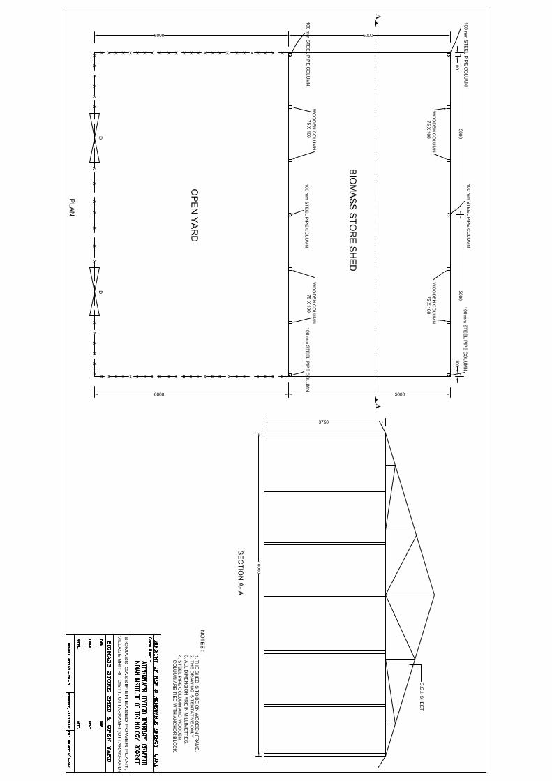
DRAWINGS 1. C – 361 -1 - Index map of Bhitri 2. C – 361 -2 - Tentative Layout of Distribution Line in Village Bhitri 3. C – 361 -3 - Schematic Diagram and Indicative Plan Layout 4. C – 361 -4 - Plan and Sectional Elevation of Power Generation Plant 5. C – 361 -5 - Biomass Store Shed and Open Yard 6. E – 361 -1 - Single Line Diagram

AHEC/MNRE/C-347/AAS/Model DPR/BEP
FOREWORD (This Foreword is not part of the Model DPR) The Ministry of New & Renewable Energy, Government of India (MNRE) have identified over 24,000 remote villages which are proposed to be electrified through small renewable energy sources e.g. Small Hydro Power, Biomass Gasification and Solar Photovoltaic Technology, so as to improve the well being of population living in the far flung isolated areas.
To make the Remote Village Electrification (RVE) programme successful, it is necessary that the planning, design, execution and operation and maintenance of RVE projects is efficient and reliable and also economical in the long run. MNRE, vide letters number 13/5/2005 – 06 RVE dated 23.12.2005 and even number dated 09.03.2006 has asked the alternate Hydro Energy Centre, IIT, Roorkee (AHEC) to prepare model detailed project reports (DPRs) for the following four categories :
1. Category “A – 1” Village with 40 households in the hilly area. 2. Category “A – 2” Village with 40 households in the plain area. 3. Category “B – 1” Village with 200 households in the hilly area. 4. Category “B – 2” Village with 200 households in the plain area.
The villages are to be selected from the States of Madhya Pradesh, West Bengal, Jharkhand and Uttarakhand to make the DPRs more versatile and practical so that these model DPRs can be used with slight site specific changes by even those users who may not have much technical expertise.
This Document has been prepared for RVE through Biomass gasification based electric Power Plant for the Category “B-1” village: Bhitri (District– Uttarkashi, Uttarakhand) and also to serve as a Model Document recommended for use as a guide for RVE of similar category villages (including those ones having some variation in number of house holds) with plant and site specific modification. Any suggestions from institutions, organizations, users and interested individuals are welcome. Suggestions should be addressed to: Head, Alternate Hydro Energy Centre, Indian Institute of Technology, Roorkee – 247667, Uttarakhand, India. E-mail: [email protected] Fax: +91 – 1332 – 273517.

AHEC/MNRE/C-347/AAS/Model DPR/BEP
EXECUTIVE SUMMARY
With the rapid changing scenario of fast depleting conventional energy sources, rapid grooving demand of power the future of conventional electric power systems are getting uncertain. This has led to world wide thrust on development and use of non-conventional energy sources for electric power generation & use. This coupled with almost no chances of extending the electric power grids to the village located in the isolated placed deep inside the forest zone. Village Bhitri, in the Block Mori of Uttarkashi district of Uttarakhand is such a backward and schedule cast dominated village, where habitants are poor and deprived of normal liying status. Most of the families are marginal farmers or labourers and are below poverty line and even some of them are jobless. The Biomass gasifier based electric power plant proposed for this village will be helpful for:
i. Improving the condition of village. ii. Generate new opportunities for upliftment. iii. Provide light to school going children for study promising better future. iv. Provide drinking water facility in the village. v. Create awareness about the renewable sources of energy and using them for
entrepreneurship like cottage industries etc. The project is envisaged to be constructed in a period of 12 months from the date of signing the contract agreement. The estimated cost of the proposed 50 kW electric power project works out to Rs. 87.257 lacs. The cost of generation work out to Rs.13.654 per kWh and 18.193 per kWh with subsidy at 80% & 60% LF respectively and Rs 15.792 per kWh and Rs. 21.043 per kWh without subsidy at 80% & 60% LF respectively. Villagers are not in a position to bear a part of the cost of the project or to pay the generation cost as per usage, it is envisaged that each family will contribute a sum of Rs. 1000.00 towards the capital cost and 4 points load consumer will pay every month Rs. 150.00 and 3 point load consumer will pay Rs. 100.00 each, on monthly basis. The running and maintenance of the project will be done by a committee formed by the villagers and Van Samiti of the Panchayat. The source funding for the as follows:
i. Incentive subsidy by MNRE : Rs. 17.18 lacs ii. One time contribution by villagers : Rs. 1.45 lacs iii. Balance to be paid by Nodal Agency : Rs. 68.627 lacs

AHEC/MNRE/C-347/AAS/Model DPR/BEP S-1
SALIENT FEATURES
1.1 GENERAL
i. Name of the Project : Biomass based Project, Electric Power Project for Bhitri Village
ii. Location a. Village : Bhitri b. Block : Mori c. District : Uttarkashi d. State : Uttarakhand
iii. Access
Road : Dehradun –Mori (240 km) Mori to Naitwar (12 km), Naitwar to Dhaula (11 km) Dhaula to Bhitri (6 km) Bridle path.
iii. Geographical Co-ordinates a. Latitude : Approx.-31007’12” N b. Longitude : Approx.-78006’ 11”E
iv. Climatic Conditions a. Temperature (ºC) : 300C Max 050C Min.
b. Humidity (%) : 70% Max. 55% Min. c. Period of Rainfall : July to September d. Rainfall : Approx. 1500 mm v. Land for Project Construction
a. At Biomass source Site : To be earmarked by Van Samiti of Village b. At proposed plant site near : To be provided by villagers.
the village Bithri vi. Approximate distance of
a. Biomass Source from Village : Surrounding the village:- 1 to 2 km b. Proposed Plant site : By the side of the Village.
1.2 DETAILS OF BIOMASS AVAILABLE IN THE FOREST IN THE SURROUNDING AREA
The area is having thick plantation. The dominant species are Kilmora, Burass and Banjh
(oak) Sagon etc. Thick forest is found at a distance nearly 2 km from the Bhitri in the Rupin Nadi domain.
It is proposed to have the plantation of Kilmora etc. in an area of 20 Ha to maintain regular supply for the plant.

AHEC/MNRE/C-347/AAS/Model DPR/BEP S-2
1.3 CIVIL STRUCTURES (Date given here are Tentative only)
Proposed Land for
i. Biomass store shed with open yard : 5.0 m x 10.0 m, 6.0 m x 10.0 m ii. Cooling Pond : 2.50 m x 5.0 m x 1.50 m iii. Gasifier shed : 5.0 m x 5.0 m x 8.0 m iv. Filter Shed : 8.75 m x 5.0 m x 5.0 m v. Power Plant Building : 5.0 m x 3.0 m x 3.50 m vi. Control Room : 3.50 m x 3.0 m x 3.50 m vii. Toilet : 3.50 m x 1.50 m X 3.50 m
1.4 POWER HOUSE (Date given here are Tentative only)
i. Gassifier Type : Down Draft ii. Gas Engine
a. Nos. : 2 b. Rating : 2 x 25 kW c. Rated Speed : 1500 rpm
iii. Alternator
a. Nos. : 2 b. Power Output Rating : 25 kW Each, 3 Ø c. Nominal Voltage of Generation : 400 V – 430/230 + 10 V d. Frequency : 50 Hz + 3% e. Power Factor : 0.8 lag f. Cooling : Natural / Open
1.5 POWER EVACUATION AND DISTRIBUTION SYSTEM
Distribution System shall be made as per the site conditions and location of various house holds and other user points. a. No. of House Holds : 145 (Approx.) b. L.T. Distribution Line
• No. of Lines : 2 • Voltage : 230 V • Length of Line : 2.5 km (Approx.)
c. No. of Street Light Points : 15 (Approx.)
1.6 ESTIMATED COST OF THE PROJECT
i. Cost of Civil Works : Rs. 33.62 Lac ii. Cost of the Plant : Rs. 42.34 Lac iii Distribution System : Rs. 4.10 Lac iv. Other expenses : Rs. 7.197 Lac v. Total Project Cost : Rs. 87.257 Lac
1.7 COST OF GENERATION
i. Without Subsidy Rs./kWh a. At 80% LF : 15.792 b. At 60% LF : 21.043
ii. With Subsidy Rs./kWh a. At 80% LF : 13.654
b. At 60% LF : 18.193

Photo -1 : A View of Village Bhitri
Photo -2 : Another View of Village Bhitri
AHEC/MNRE/C-347/AAS/Model DPR/BEP P-1

Photo -3 : A View of Panchayat Bhawan at Village Bhitri
Photo -4: Ground for Social Activities at Village Bhitri
P-2AHEC/MNRE/C-347/AAS/Model DPR/BEP
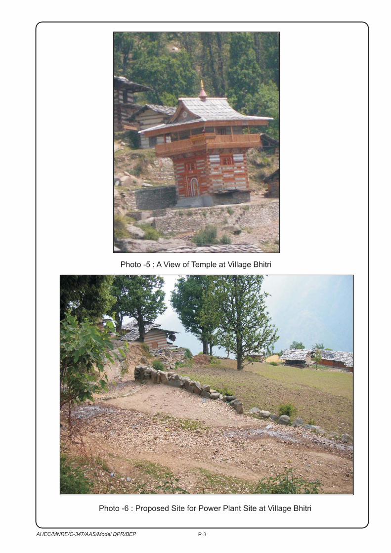
Photo -6 : Proposed Site for Power Plant Site at Village Bhitri
Photo -5 : A View of Temple at Village Bhitri
P-3AHEC/MNRE/C-347/AAS/Model DPR/BEP
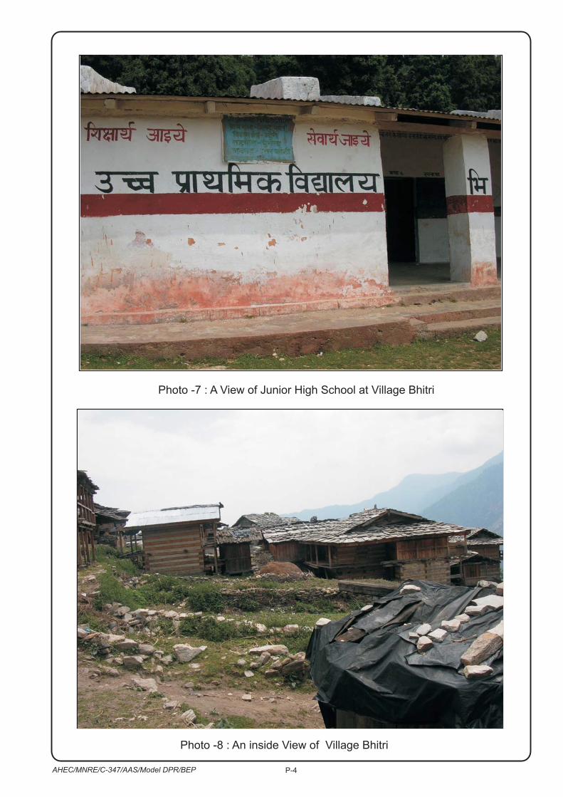
Photo -7 : A View of Junior High School at Village Bhitri
Photo -8 : An inside View of Village Bhitri
P-4AHEC/MNRE/C-347/AAS/Model DPR/BEP

Photo -9 : A View of Waste Wood Around the Village Bhitri
Photo -10 : A View of a Hand Loom in Village Bhitri
P-5AHEC/MNRE/C-347/AAS/Model DPR/BEP

AHEC/MNRE/C-347/AAS/Model DPR/BEP
1
CHAPTER – 1
BASIC DATA 1.1 INTRODUCTION
There is acute shortage of electric power generation in the country so much so that the areas already connected to the power grids are subjected to frequent power cuts or same time due to topographical problem power generation and distribution may not possible. The available fuel resources being used for electricity generation are getting fast depleted. These problems and sensitivity coupled with the isolated villages, make it impossible to connect them with the grid. The economic and social conditions of the inhabitants of the, isolated, unelectrified remote villages in the interiors of Uttarakhand State are very poor. Electricity being one of the basic infrastructural requirements for development and progress, the only hope in the above scenario is the use of renewable energy sources to generate and supply electricity to the remote villages. In an effort towards this end, this project has been conceived for immediate electrification of village Bhitri in the Mori block of district Uttarkashi in Uttarakhand
1.2. PROJECT SPONSOR
MNRE, vide letters number 13/5/2005 – 06 RVE dated 23.12.2005 and even number dated 09.03.2006 has asked the alternate Hydro Energy Centre, IIT, Roorkee (AHEC) to prepare model detailed project reports (DPRs) for the following four categories:
1. Category “A – 1” Village with 40 households in the hilly area. 2. Category “A – 2” Village with 40 households in the plain area. 3. Category “B – 1” Village with 200 households in the hilly area. 4. Category “B – 2” Village with 200 households in the plain area.
The villages are to be selected from the States of Madhya Pradesh, West Bengal, Jharkhand and Uttaranchal to make the DPRs more versatile and practical so that these model DPRs can be used with slight site specific changes by even those users who may not have much technical expertise.
MNRE, Government of India is subsidizing the cost of Remote village electrification projects to a large extent. The balance project cost is generally met by the Nodal Agency and the people of the villages.
1.3. NODAL AGENCY & ASSOCIATED ORGANIZATIONS
Uttarakhand Renewable Energy Development Agency, has been assigned to carry out energy development work through non-conventional energy sources by the Government of Uttarakhand. For the present DPR works UREDA has been nominated as Nodal Agency by the MNRE.
AHEC/MNRE/C-347/AAS/Model DPR/BEP
2
In identification and selection of the village to be electrified the cooperation was sought from various Van Samits along with The Department of UREDA.
1.4. SELECTION OF VILLAGE FOR MODEL DPR Reconnaissance survey was undertaken to various remote villages located in the Mori block for selection of village(s) as per suggestion by UREDA. After gathering information and data, interacting with the local people and the village level organizations e.g. Gram Panchayat, Van Surksha Samiti etc and visual survey and assessment of various aspects related to the generation of power through bio- mass and electrification of remote village, Bhitri village was selected for preparation of Model Detailed Project Report.
Here it is intended to electrify the Bhitri, remote village of District Uttarkashi. The villagers are subjected to isolated life, having limited resources and access. Their income is also restricted to marginal cultivation, occasional labour and through goats, poney and poultry trade. People are trying hard to uplift the lifestyle for which they have established a place for social get togethers club in the village.
To uplift the life of this village dominated by, tribal community (60%), it is essential to provide electricity so as their living standard can be raised and they can augment their income through cottage industry etc.
It is next to impossible to get the power through grid, therefore, it has become imperative to provide the power to this remote village through a non conventional source of energy. Due to availability of biomass in the surroundings of the village, the electrification through biomass gassifier has been selected for the village.
1.5. GENERAL INFORMATION – VILLAGE BHITRI 1.5.1. Location And Access
Bhitri village in the District of Uttarkashi of Uttarakhand State is a human settlement located in interior corner, by the side of Rupin Nadi. It is linked with National highway up to Naogaon and from there to block Mori through Jeepable road. Further from Mori to Dhaula by Jeepable road from where a Kachchaha track (6 km) links with village Bhitri. The nearest railway station Dehradun is situated at about 220 km from the village.
1.5.2. Socio-Economic Status
Bhitri village is dominated by tribal community having 60% population. It is having 145 households with a population of 859 persons. Each family consists of 5 to 7 members. Most of the villagers are marginal farmers having limited infrastructural facilities. Main crops of the area are Potato, Razma, Kulath etc. At places rice and vegetables are also grown. The main cash crop of the area is Potato Rajma and vegetables, which are grown by nearly every villager in a typical manner.
AHEC/MNRE/C-347/AAS/Model DPR/BEP
3
Nearly all the inhabitants are engaged in the cultivation and labour related with the development of Sheep, goats etc. Wood is used for cooking proposes. In general the income of a family varies between Rs.2000.00 to Rs.4000.00 pm. There is considerable disparity amongst the people of the village. Most of the villagers have Kachcha tiled roof houses whereas, few poor families have thatched roof houses.
1.5.3 Additional sources of income To augment their income most of the families keep domestic animals. Nearly a family keeps 1 to 2 cows, 1 to 2 buffalos and upto 100 goats. Poultry on small scale also contribute to their income. Poney is main source of income for them, which is used for transporting the goods from Dhola to the interior places. In the summer season they also transport tourists to higher reaches.
1.5.4 Education
Bhitri village is having a one primary and one middle school only. The nearest higher education college/ school is nearly at Naitwar or Purola. Overall education level of the village as revealed by Panchayat members is as follows: Post Graduate - 05 Graduate. - 10 12th standard - 10 10th standard - 25 8th standard - 45 5th standard - 150
1.5.5 Health
People are in general having good health. In case of illness people have to travel to Mori for preliminary treatment at PHC. For hospital facilities they have to go to Purola.
1.5.6 Roads and transport Village Bhitri is connected with Base camp Dhola through 6 km Kachcha road. Dhuala is connected with Mori though 23 km Jeepable road. Mori is linked with national highway 123.
1.5.7 Electricity availability Village is located deep in the forest, where transmission lines cannot be drawing though thick forests. The village is un-electrified and the possibility of getting power from the grid is also remote. Two or three Villagers do have solar home modules. Kerosene is being used for illuminating the houses.
1.5.8 Water availability
Drinking and irrigation water is drawn from the rivulet and Nalas encircling the village.

AHEC/MNRE/C-347/AAS/Model DPR/BEP
4
1.5.9 Communication The village is totally isolated and not having any mode of communication with the rest of the world.
1.5.10 Haat/ Market Market facilities are available at Naitwar and Mori.
1.5.11 Grazing ground and Fodder Village is not having any defined grazing grounds whereas forest land or barren waste land is serving as grazing grounds for domestic cattle’s. Fodder in the form of leaves and grass is also collected from these areas.
A certain nominal amount of fodder is also obtained by the villagers from the crops.
1.6 FOREST AROUND BHITARI Bhitri village is located close to the bank of Rupin Nadi which is vegetated area but the true forest is not found. The dominant species are Kilmora, Burass, Banjh, Conifers etc.
1.7 WOOD AS FUEL Villagers are collecting wood from the forest and use it for cooking. Wood logs are also collected from the forest for construction and repair of the houses. Villagers collect the wood in their compounds for monsoon and winter seasons. Cow dung from domestic cattle’s is used for preparation of organic manure.
1.8 FOREST LAND UNDER VAN SAMITI Bhitri Gram Panchayat Van Samiti is having sufficient barren land under their management. The land available along the outer fringe of the village is found suitable for cultivation of woody plants for biomass gassifier.

AHEC/MNRE/C-347/AAS/Model DPR/BEP
5
CHAPTER – 2
LOAD ASSESSMENT/ENERGY REQUIREMENT AND INSTALLED CAPACITY
2.1 GENERAL 2.1.1 Village Layout And Type of Houses
Village Bhitri is located in the higher Himalayas. The villagers are having their houses spread over a large area on the right side slope of the Rupin Nadi. In the village most of the houses are Kachcha having tiled roots. Few houses, of poor people have thatchat roofs. Nearly 45 houses are having 4 to 5 rooms and 100 houses have 2 to 3 rooms. Gaushalas are generally by the side of these houses. Few families are having separate Gaushalas.
On detailed questioning and assessment it was found that 45 big houses will opt for 4 points load only. The two points having 15 W CFLs, will be used for illumination through out the evening and morning hours. One point will be used for radio/television etc. These house owners will go for one more bright light point (60W). The remaining points will be used off and on, based on the actual requirement. The smaller houses will require only 3 points load (15 W CFL, 60 W Blub, 60W TV/Radio). On the whole two/three illuminating points will have 100% diversity factor and the remaining points will have 200% diversity factor.
2.1.2 Use of Electricity
The use of electric power is proposed for: i. Domestic Uses ii. Public Lighting iii. Multi-purpose Uses
2.1.3 Load Assessment
Electricity will be used in the following manner:
i. Out of 145 houses, 45 households will go for 4 points connections and 100 households will take 3 points load. On an average, 3 points will be used by each household.
The power for domestic purposes will be used for 6 hrs in a day, 2 hrs in the morning (5.00 to 7.00) and 4 hrs in the evening (1730 to 2130 hrs). In that area sunsets early and the village life settles around 8 pm, therefore, longer use of power in the evening is not expected.

AHEC/MNRE/C-347/AAS/Model DPR/BEP
6
It is expected that out of 4 point load people will use 2 points for 15 W, CFLS, 1 point for 60 W bulb, and 1 point for radio/TV, having about 100W load. Thus a total of 200W load will be taken by 45 households. The 3 points load users will use 1 point for 15 W CFL, and 2 other points for bulb/other use. Thus a load of about 150 W will be taken by remaining 100 house holds. On an average a household will have a load of 165W.
ii . Public lighting up to 15 points @ 18 watts (CFL) per point for 4 hours in the evening. iv. Multipurpose uses e.g. pumping for irrigation, needs of agro-based cottage industries,
lighting of places of worship, battery charging, needs of shops, clinics etc. which may come up in due course of time. Power is also required for processing rice in the area. It is envisaged that the use of power in such activities will be used after the domestic use hours. Therefore, the requirement of the power for this use is not being accounted for. Power for such use can be drawn in the day hours by running the power plant.
v. Future expansion: assumed as 15% in ten years. Due to poor living conditions people are found migrating to better places in search of jobs. This is the main reason for negligible growth of the village. With the provision of power it is expected that this migration will be checked to some extent
2.2 POWER / ENERGY REQUIREMENT
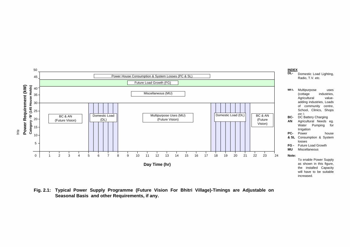
The requirement has been worked out as per the consideration above and the criteria discussed below and summarized in Table 2.1. Typical power supply demand and future programme (Future Vision) are shown in Fig. 2.1.
i. Domestic Uses
-Connected load, as per discussions earlier is 165 W -Diversity factor
-CFL and 60 W bulb100% -Other load -200% -Actual load -123 W -Supply hours -6hrs/day -Energy consumption per H.H per day = 123 X 7 = 861 Watts hrs. Say = 0.861 kWh/day -Total power requirement for 145 H.H = 165 X 145 watts = 23925 kW Say = 25 kW
- Total energy consumptions per day for 145 H.H = 0.861 X 145 kWh = 124.845 kWh
ii. Public Lighting
It is proposed that public lighting will be used for 4 hours in the evening and 2 hours in the morning only. The final operation and maintenance is conceived to be

AHEC/MNRE/C-347/AAS/Model DPR/BEP
7
in the hands of the local body of the village and accordingly public lighting and other loads will be managed by them as per their choice, and hence the number of hours of usage will be finalized.
a. No. of light points – Up to 15 b. Type of lighting – 18 watts CFL c. Lighting hours – 4 hours in the evening & 2 hours in the
morning d. Power required – Up to 18 x 15= 270W or 0.270kW e. Energy consumption – Up to 0.270x 6 kW hrs or 1.620 kWh
iii. Multipurpose Uses
Depending on requirement and willingness of the people, the plant can be operated for the required number of hours between 9 a.m. to 5 p.m. The power availability for multipurpose use will be limited to about 40 kW only. This requirement can not be assessed at present.
vi. Installation Capacity of Power Plant
Assuming power house consumption @ 10 %, line losses @ 5 % and the future growth @ 15 % in next 10 years, the Power Plant installation capacity is worked out as below: a. Domestic load = 25 kW b. Public Lighting = 0.27 kW c. Future Growth = 0.15 x 25 = 3.75 kW
Sub-Total (a to c) = 29.02 kW d. P.H. consumption/system losses = 0.15 x (29.02) = 4.353 kW
Total = 33.373 kW Say, = 50 kW
The biomass gasifier based power plant do not yield the desired output and it is also possible that people may use some equipment continuous duration, therefore, the capacity of power plant has been taken as 50 kW.
vi. Energy Consumption per Day
a. Domestic use = 108.75 kWh b. Public lighting = 1.620 kWh c. PH consumption (4.353 x 7) = 30.471 kWh Total = 140.841 kWh Say = 141.00 kWh
The consumption in respect of multipurpose uses has not been considered here as the same may take some time to come up. However, depending upon the number of hours of running of this load additional energy consumption will be there.

AHEC/MNRE/C-347/AAS/Model DPR/BEP
8
The proposed daily use requirement of power and energy consumption is summarized in Table 2.1 below:
Table : 2.1 – Proposed Daily Use Requirement
Daily Use requirement of Sl. No.
Use Power (kW) Energy (kWh)
1 2 3 4 1. Domestic Use 25.00 124.845 2. Public Lighting 0.270 1.62 Sub Total (Item 1 to 2) 25.27 126.465
4. Future Expansion @15% 3.79 18.97 5. PH Consumption, Losses etc. @ 15% 4.353 30.471
Total 33.373 175.906 Capacity Taken as 50.00 176.00
50 INDEXDL-
45
MU-
BC- DC Battery ChargingAN
PC- & SL
FG - Future Load GrowthMU Miscellaneous
0 Note:
Fig. 2.1:
40
8(a)
Typical Power Supply Programme (Future Vision For Bhitri Village)-Timings are Adjustable onSeasonal Basis and other Requirements, if any.
2421 2219
Power houseConsumption & Systemlosses
2 3 1885 1276
Domestic Load Lighting,Radio, T.V. etc.
Multipurpose uses(cottage industries,Agricultural value-adding industries, Loadsof community centre,School, Clinics, Shopsetc.)
Agricultural Needs eg.Water Pumping forIrrigation
Pow
er R
equi
rem
ent (
kW)
Day Time (hr)
13 14 15 16
35
2317 20
30
25
5
20
15
To enable Power Supplyas shown in this figure,the installed Capacitywill have to be suitableincreased.
Cat
egor
y -'B
' (14
5 H
ouse
Hol
ds)
41 9 10
10
11
BC & AN(Future Vision)
BC & AN(Future Vision)
Multipurpose Uses (MU) (Future Vision)
Domestic Load (DL)Domestic Load (DL)
Power House Consumption & System Losses (PC & SL)
Future Load Growth (FG)
Miscellaneous (MU)
AHEC/MNRE/C-347/AAS/Model DPR/BEP
9
CHAPTER – 3
RESOURCE AVAILABILITY AND MANAGEMENT 3.1 BIOMASS 3.1.1 Availability
The above remote electrification scheme requires a suitable, continuous and reliable source of Biomass, which should be available within 2 to 3 km from the power house site. Bhitri village is surrounded by slightly vegetated area which is dominated by Chir, Kilmora, Burass, Banjh trees. Forest area is around Bhitri village in the Rupin Nadi domains. Most of the shrubs have wild and thick growth, and are undesirable elements in the development and growth of new plants. These shrubs are available in the area which can be used in the gasifier unit. It is likely that these shrubs may provide fuel for few years only and based on the long term strategy, these shrubs or fast growing plants like have to be grown on the panchayat or the Van Samiti land. The location of power house has been tentatively selected in the central part of the village close to the houses. Near to this site degraded/waste land having growth of wild shrubs is existing, which can be utilized for development of biomass for regular supply to the power house. This regular supply can be assured through plantation of fast growing trees requiring minimum water. Considering the topography, drainage and nature of soil, the plantation of has been found most suitable for the area. Forest Officials were also in agreement with this. According to them Van Samiti Panchayat can provide land and expertise for the same.
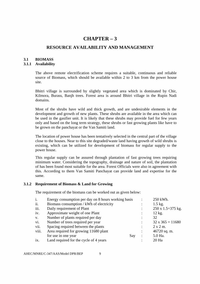
3.1.2 Requirement of Biomass & Land for Growing
The requirement of the biomass can be worked out as given below:
i. Energy consumption per day on 8 hours working basis : 250 kWh. ii. Biomass consumption / kWh of electricity : 1.5 kg. iii. Daily requirement of Plant : 250 x 1.5=375 kg. iv. Approximate weight of one Plant : 12 kg. v. Number of plants required per day : 32 vi. Number of trees required per year : 32 x 365 = 11680 vii. Spacing required between the plants : 2 x 2 m. viii. Area required for growing 11680 plant : 46720 sq. m.
for use in one year Say : 5.0 Ha. ix. Land required for the cycle of 4 years : 20 Ha

AHEC/MNRE/C-347/AAS/Model DPR/BEP
10
3.1.3 Plantation of In general it may require, 4 years period for the plants to grow to the size needed for the present use. It is suggested that 4 separate areas of the size 5 Ha. each should be ear marked close to the village and power house plant. A small area has to be earmarked for the nursery also. For the first two to three years the waste produced from the resources already available in the form of shrubs, Pine, Buras, Banjh etc. will be utilized. In the meanwhile the plantation will be done over the land (20Ha) demarcated in the 4 segments of 5 Ha each. The nursery will be maintained for regular plantation and replacement of dead plants. Though the plants will take around years to grow, but the first lot can be drawn from the 3rd year itself as the rainy season in the area is always prolonged, and the growth of plants is faster. i. The plantation shall be done by the villagers under the supervision of the Van
Samiti of the village panchayat in a manner that continuous supply of biomass shall be available for the Gasifier plant, as per the requirement from the 5th year onward.
ii. The households will manage the supply of the biomass to the Gassifier plant by
rotation. The arrangement of the transport will be through carts/or head load as the distance will not be much.
iii. Biomass will be collected, dried in advance and stocked in the sheds meant for it so
as to ensure reliability. iv. The nursery will also be managed by the people of the village where the seeds will
be sown as per the requirement, plants shall be grown and maintained for about a year and then transplanted in the earmarked areas.
v. Arrangement of seeds, manure etc will be managed by the Forest Department /
Nodal agency. vi. A tube-well will be bored in the nursery area for watering the plants. vii. Plantation will not require regular watering as it is a plant of arid to semiarid region. viii. The growth rate of the plant being very good, sufficient amount of biomass shall be
available from the said plantation for continuous, successful and reliable working of the Gasifier plant.
AHEC/MNRE/C-347/AAS/Model DPR/BEP
11
3.2 BIOMASS MANAGEMENT
The management of the Biomass plantation is proposed to be done by the committee formed by the villagers and Van Samiti under the supervision of UREDA and Uttarakhand Forest Department.
3.3 RESOURCES OF OPERATION AND MAINTENANCE i. Local person/persons from nearby area having reasonable reading and writing
skills, suitable intellectual capacity and willingness to work as operator/ maintenance staff, is to be identified.
ii. Facility to provide an on situ training to the above persons, is to be provided. iii. Tools and plants, gadgets, safety equipment, etc. as required for maintaining the
plant and distribution system, are to be provided. iv. Spare parts for successful operation of the system for 10 years period, are to be
made available. 3.4 MONETARY RESOURCE
The scheme is to be funded: i. Partially by the MNRE, ii. By initial lump sum contribution by the village people iii. Balance by the Nodal Agency.
3.5 NODAL AGENCY FOR INSTALLTION OF THE PLANT
UREDA, the Nodal Agency for this project will be responsible for planning, designing, processing the purchase case, placement of order, supervising construction, liaison etc.
3.6 O & M ACTIVITIES The management, operation and maintenance of the plant (including distribution system) will be carried out by the contractor for initial 5 years period and thereafter by the committee formed by the Bhitri village in association with Van Samiti and UREDA.

AHEC/MNRE/C-347/AAS/Model DPR/BEP
12
CHAPTER - 4 CIVIL WORKS
4.1 INTRODUCTION
The civil structures for the proposed Biomass based Electric Power Plant (BEP) will comprise: i. Biomass Store shed with Open yard for drying, ii. Gasifier shed, iii. Filter Shed iv. Cooling Pond, v. Power House Building, vi. Control Room, vii. Water supply System (including room), viii. Construction of boundary wall, fencing etc., ix. Any other facility as may be required,
4.2 CIVIL WORKS
The civil works will consist of the different components as described below. The dimensions stated in the test are tentative only and can change depending of on the final selection of equipments.
4.2.1 Biomass Store Shed with Open Yard A 5.0 m x 10.0 m store shed is required. It is proposed to have CGI sheet wall on wooden frame & CGI sheet cover on tubular truss. An open yard for drying of biomass is proposed to be located near the shed. The open yard having barbed fencing will be 6.0 m x 10.0 m size.
4.2.2 Cooling Pond A 5.0 m x 2.50 m x 1.50 m cooling pond is proposed to be constructed by the side of gassifier unit within the gasifier shed.
4.2.3 Gasifier Shed An open gasifier shed of size 5.0 m x 5.0 m having CGI sheet roofing on tubular truss is proposed to be constructed for housing the biomass gasifier of the plant.
4.2.4 Filter Shed An open filter shed of size 8.75 m x 5.0 m having CGI Sheet roofing on Tubular truss is proposed to be constructed for housing the filters.
4.2.5 Power House Building A power house building of size 10.0 m x 6.0 m is to be constructed to house the gas engines, the generators and their auxiliaries. This building may be constructed with 250 mm thick stone or brick walls having CGI sheet roofing.
4.2.6 Control Room The control room will be of 3.50 m x 3.0 m size, placed by the side of the P.H. building, It may be constructed with 250 mm thick brick walls and RCC roofing.

AHEC/MNRE/C-347/AAS/Model DPR/BEP
13
4.2.7 Toilet 1.5 m x 3.0 m size toilet will be provided at the site.
4.2.8 Any Other Building / Structure : As may be required. 4.3 CONSTRUCTION
i. Minimum clear height of the sheds and buildings is to be as given below:
a. Biomass Store : 3.60 m b. Gasifier shed : 8.00 m c. Filter Shed : 5.00 m d. P. H. Building : 5.00 m e. Control Room : 3.50 m f. Toilet : 3.50 m
ii. The foundation bed of the generator shall be at least 200mm above the floor level and have provision for grouting of bolts, studs and anti-vibration dampers. Arrangement shall be made for water proofing and foam layer to damp vibrations.
iii. The foundation shall be located at least 300 mm away from the column footings and plinth beam to avoid transmission of vibrations caused by the generating sets.
iv. Adequate arrangement for proper ventilation shall be provided. It shall include exhaust fans and smoke exhaust pipe located in a manner to ensure dissipation of smoke in direction away from the building.
v. The floor of control room and toilet shall be made of good quality mosaic with best quality white cement and marble chips.
vi. Inside brick wall shall be plastered and white wash distempered. vii. Windows/ventilators shall be fixed to ensure natural lighting inside the
buildings. viii. Proper equipment fitting facility shall be provided. x. Proper lighting arrangement shall be made both inside and outside the
buildings / sheds and approach road. xi. The construction is to be done as per the Approved drawings. xii. The structural design shall be done based on soil test, stability and safety
factors etc. xiii. The construction is to be carried out as per the National Building Code of
India, unless otherwise approved. xiv. Foundation for holding and grouting the gasifier unit etc. shall be made in
1:2:4 RCC or as Approved. xv. Any other arrangement required as per site condition shall be made to ensure
proper functioning of the plant and the system.
4.4 WATER SUPPLY SYSTEM AND ROOM
4.4.1 Setting up of water supply system
i. Water supply system will be placed inside a room of appropriate size. ii. Installation of a 1 HP submersible type motor-pump unit, the motor being of
Siemens /NGEF / Cromton / Jyoti / Kirloskar make operable on 230 V, 50 Hz, 0.8 PF AC supply.
iii. Boring and installation of tube well.

AHEC/MNRE/C-347/AAS/Model DPR/BEP
14
iv. Water piping system including bends, sockets, valves, clamps, civil works etc, will be of galvanized components.
4.4.2 Boring etc.
Boring of tube well up to required depth and of required diameter, through all type of soil strata present. Works will include scaffolding, lowering of pipes, strainers, blind pipes including bucket washing etc.
4.4.3 Storage Tank A 10000 litres PVC water storage tank of Sintex /Palton or equivalent will be installed on a fabricated platform at a height of 6.0 m.
4.5 MISCELLANEOUS
4.5.1 Gate The main gate is proposed to be 4 m (wide) x 1.80 m (high) comprising 2 panels made of MS angle frame and rods with guide Track etc. supported on 2 numbers 400 mm x 400 mm RCC pillars on both sides.
4.5.2 Fencing Pre-cast RCC posts, 2 m high with 0.3 m bend at the top, is to be erected and chain link fencing (50 mm x 50 mm x 8 SWG size) fixed with the RCC posts by means of galvanized clips to a grid of horizontal strands of galvanized high tensile spring 12 SWG steel wire.
4.5.3 General Facilities Drinking water supply system, Toilets etc. are to be provided in the P.H. building.
4.5.4 Approach Road Suitable approach road shall be provided from the nearest road for the required services.
4.5.6 Environmental Provisions Necessary provisions are to be made as per the requirement of environmental rules and regulations in force.
4.5.7 Safety Provision All the required provision with regard to fire hazards will be provided. 4.5.8 Fabrication of Structures
The materials to be used and fabrication and construction method, and fixing mild steel or iron work in small sizes and sections such as holding down bolts, holdfasts, tie rods, gratings etc. be as per relevant Indian Standards.
4.5.9 Painting Steel work is to shall be thoroughly cleaned of rust, loose scales, dust etc. as per latest edition of IS: 1477-part-I and given one coat of red oxide paint conforming to IS: 2074 applied as per IS: 1477-part-II. Over surface inaccessible after placing in position, two coats of red oxide paint should be applied.

AHEC/MNRE/C-347/AAS/Model DPR/BEP
15
CHAPTER -5
POWER GENERATION EQUIPMENT
5.1 TYPES OF GASIFIER 5.1.1 The following types of gasifier are available
i. Down draft or Co-current ii. Updraft or Counter-Current iii. Cross Draft iv. Fluidized Bed System The use of small down draft gasifier has long history in the world. During the world war-II, number of cars, buses and boats were operated by down draft gasifier using wood as fuel. The down draft gasifier have a number of advantages over the others, which make it most convenient and efficient to use. The main advantage of down draft gasifier is the fact that the pyrolysis products have to flow co-currently through the hot combustion and gasification zones, where most of tars are decomposed and oxidized. Thus the producer gas from a down draft gasifier, after simple filtration and cooling, can be used in an internal combustion engine. Hence down draft type gasifier is recommended for power plant.
5.1.2 Capacity of Gasifier The capacity of the gasifier should be suitable to operate 50 kW (electrical net output) gas engine genset with likely gross output of 60 kWe.
5.1.3 Material of Construction of Gasifier Reactor inner shell, combustion cone, scrubber, throat and nozels to be of stainless steel. The other non MOC part should be of standard carbon steel.
5.1.4 Specifications of Gasifier Average Calorific Value - Not less than 1000 k cal/Nm3 Turn Down Ratio - 1:0.3 (Minimum) Biomass Consumption - 1.5 + 0.1 kg/kWh Hopper holding capacity - More than 350 kgs. Biomass Feeding internal for batch operation- Every 2 hours
Period of continuous running - 24 hours Starting time - Within 15 minutes Starting method - Through auxiliary power - Auto start through battery by starting scrubber pump/engine suction Reduction Bed Control - Through an automated control system
to result in reasonably constant gas flow rate and gasifier pressure drop without any manual intervention for reasonable period.
Biomass Feeding System - Manual through small ladder or a bucket elevator. Biomass
AHEC/MNRE/C-347/AAS/Model DPR/BEP
16
feeding should be online without stoppage of system.
Ash Char Removal - Continuous online. Filtering Arrangement - Minimum One no. Check (fabric) filter
and two nos. of fine filters along with wet scrubber to be provided. Biological filter media shall be used in fine filter.
Biomass Sizing Equipment - Through suitable motor operated cutter. . Biomass (wood) drying Device - Through Engine Exhaust Based Dryer Painting of all gasifier system - All exposed steel/iron parts (major /
minor) if any of all gasifier systems must be suitably painted and protected against corrosion due to high humid saline atmosphere during the guarantee period.
5.1.5 Specification of Gas Cooling & Cleaning System Gas Quality - For gas engine operation, an extremely
clean & cooled gas is essential. Tar & Particulate matter should be less than 25 mg/cu.m.
Type of Filter Material - Biological or fine filter cloths shall be used.
Material Life of Checking filter cloth - Minimum 1000 hours Interval of cleaning - Minimum 50 hours Cooling System - The gas temperature at engine inlet
should not exceed + 50C of ambient or 400C, which ever is less.
5.1.6 Woody Biomass Fuel Size The following size of the biomass fuel is to be used: i. Maximum diameter and length: 75 mm and 100 mm respectively ii. Minimum diameter and length : 10 mm and 10 mm respectively
5.1.7 Blower
i. The blower should be of suitable rating and capacity as per the Standard Specifications followed.
ii. The body and the impeller shall be made of SS-316 having thickness not less than 2.5 mm and 2 mm respectively and suitable for the required flow rate and pressure.
iii. The blower is required to be suitable for regulating the gas flow and its flaring as and when necessary.
5.1.8 Pumps
Pumps of suitable rating and quality as per the Standard Specifications to be followed and having preferably rotational speed of 1500 rpm should be provided for:
AHEC/MNRE/C-347/AAS/Model DPR/BEP
17
i. Cleaning and cooling of the producer gas. ii. Cleaning of ash pond(s).
5.1.9 Gasifier Control Panels Control panels of suitable dimensions, quality material and thickness mounted with protection equipment for required degree of protection and necessary indicators related to the operation of vibrators, motors, blowers, pumps etc and sensing devices e.g. temperature etc. as per relevant Standards are to be provided at appropriate locations as per Approved drawings.
5.1.10 Specifications of Gas Engine Gas Engine Make - Any indigenous reputed make suitable
to run on producer gas alone with rated speed not above 1500 rpm.
Specific fuel consumption under producer - 1.5 kg of woody biomass/kW-hr gas operation Power Rating of engine - 70 kW Type of governing - Mechanical Engine Starting System - Through auxiliary power
Engine lgnition System - Through pointless Distributor based ignition system
5.1.11 Bearings i. Position
The Gas Engine is proposed to be centrally mounted, having properly aligned bearings. All the bearings should be guaranteed for 5 years.
5.1.12 Pressure Gauges / Other Instruments i. Pressure Gauges
A pressure gauge is recommended to be provided in the P.H. to read the pressure of Gas just before it enters the Gas Engine. It should have scale to read approximately half- scale at gross head.
ii. Other Instruments
Other instruments of Standard make and quality should to be provided as per requirement at appropriate locations.
5.1.13 Safety Guards All moving parts should be shielded by a strong and durable wire mesh. The size of the wire mesh should be small enough to prevent the entry of hands and arms of the children. The guards should be electrically earthed and kept permanently secured by locks.
5.1.14 Spare Parts A set of recommended spare parts in respect of gasifier and gas engine for five years’ successful operation should be provided.

AHEC/MNRE/C-347/AAS/Model DPR/BEP
18
5.1.15 Tools i. Set of Tools
A set of tools is recommended to be provided. The set should include tools to test alignment and case tolerances e.g. string, steel rule, measuring tape, square, feeler gauge, dial gauge, sprit level etc.
ii. Tool Display Board Tool locations should be silhouetted on a tool display board so as to immediately make it apparent if a tool is in use or missing.
iii. Lifting hoists Suitable lifting hoists be provided in the power house.
iv. Re-chargeable Lantern A re-chargeable battery-powered lantern is proposed to be provided in the power house.
5.1.16 Type Tests The type tests should be performed as per the relevant Standards followed. The equipment offered should with stand these tests successfully or as per the recommendations / methodology of Gasifier Action Research Projects (GARP) carried out under the Ministry of New Renewable Energy Sources (MNRE), Govt. of India.
5.2 ELECTRO-MECHANICAL EQUIPMENT 5.2.1 Type of Alternator
Three phase, A.C. Synchronous Generator are recommended to be provided. 5.2.2 Specifications of Alternator
Make - Any reputed make kVA rating - > 125 kVA Voltage - 400 – 430 Volts Phase - 3φ Power Factor - 0.8 Frequency - 50 Hz
5.2.2.1 Specifications of Control Panel System - Should have all necessary switches,
timers, protection etc. as per IE standard
Meters - Voltmeter, Ammeter, Frequency meter, Energy meter of reputed make
5.2.2.2 Protection System i. Over Current and Earth Fault Protection
a. Over Current Protection Miniature Circuit Breaker (MCB) or Molded Case Circuit Breaker (MCCB) of suitable rating should be used for the purpose. These should be placed as close to the generator terminals as possible.

AHEC/MNRE/C-347/AAS/Model DPR/BEP
19
b. Earth Fault Protection An earth leakage circuit breaker (ELCB), also known as Residual current device (RCD), of suitable rating is recommended to be provided as close to the generator terminals as possible.
c. Ratings of above Protection The maximum rating of the above protections should not be more than 10 % of the current rating of the generator.
d. Location The over current and the earth fault protection may be placed in the same box with each one clearly labeled but the mounting should not be on the generator body (so as to avoid vibration damage). These should be placed at least 1m above the floor level and as close to the generator as possible with properly fixed and sealed conduit protecting the cable to the generator. The ELCB should be connected to the generator and then the over current trip should be connected to the ELCB.
ii. Voltage and Frequency Trips These are proposed to be provided to protect consumer loads from un-acceptable voltages and frequency conditions. Over Voltage, Under Voltage, Over Frequency and Under Frequency Trips are recommended to be provided:
5.2.2.3 Lightning Protection To protect the power house and the consumers, lightning arrestors are proposed to be provided on each phase as below: i. 1 arrestor on the first pole out side the P.H. and 1 arrestor per km of distribution line, ii. An additional arrestor, if a consumer is more than 500 m away from the arrestor.
5.2.2.4 Instrumentation
i. Placement These, except the kWh meter, may be included on the controller box. The height should be at the eye level or 1.5 m above the floor level.
ii. Meters Voltmeter, Ammeter, Frequency meter, Wattmeter, Ballast meter (in ELC system, 3 ballast meters- 1 per phase) shall be provided.
5.2.2.5 Controllers, Governors and Flow Regulators An Electronic Load Controller (ELC) or a combined electronic and flow governor should be provided. The controller must be located in the P.H. together with the ballast to ensure that the ballast is never disconnected.
5.2.2.6 Consumer Isolation Switch A switch, rated at current equal to or higher than that of O/C trip, should be provided in the P.H. to isolate the distribution system from the generator.

AHEC/MNRE/C-347/AAS/Model DPR/BEP
20
5.2.2.7 Earthing i. The following should be effectively earthed:
a. The neutral of the generator. b. All the metal casings of the electrical equipment etc. c. Earthing in the powerhouse should be as per the specifications of the Earth
Leakage Circuit Breaker (ELCB). ii. Precaution should be taken to prevent corrosion due to electrochemical effects,
which can be done by using copper conductor/ electrode for earthing, avoiding bi-metal joints, or by maintaining air and water exclusion from bi-metal joints.
iii. ELCB (RCD) should be used for electrical safety. iv. The earth conductor (connection from the earth terminal to the earth electrode)
should have a minimum cross-sectional area of not less than 25 sq. mm. A permanent level “Safety Electrical Connection – DO NOT REMOVE” should be provided.
V. Earthing is proposed to be done as per the REC (Rural Electrification Corporation) standard and in line with Indian Electricity Rules.
5.2.2.8 Lighting
i. The P.H. is proposed be provided with adequate safe illumination: minimum 10
watts / sq. m. of floor area, if incandescent, or 3 watts / sq. m., if fluorescent. ii. A battery-charged type lantern (emergency light) should be provided on display
board. iii. A weather proof HPSV flood light should be provided out side, above the door, on
suitable fixtures providing 20 Lux illumination. iv. Street lighting/Road should be provided with 20 Lux illumination using Approved
type lighting equipment & fixure (s).
5.2.2.9 Conduits and Cables
i. Strong conduits, physically secured to all enclosures by means of threaded connectors, should be used to protect all cables.
ii. The conduits should be sealed to the enclosure entrances. iii. Since the cable inside the conduit from generator to over current- trip / ELCB box is
not protected from over currents and earth faults, adequate physical strength of conduit should be ensured,
iv. The current carrying capacities of the cables, after taking in to account the de-rating required for use of conduit and multiple cables, should not be less than 140% of the rating of the over current protection device(s),
v. If the cables are felt over- warm on touching, it is an indication of these being under-sized. The cables should be doubled or replaced in such cases.
5.2.2.10 Sockets
Two or more sockets (outlets) should be provided for use of electrical appliances. The sockets should be placed at least 1 m above the floor.

AHEC/MNRE/C-347/AAS/Model DPR/BEP
21
5.2.2.11 Shielding
i. Cables and their connections to Units is proposed to be shielded both by conduit and by their insulation. The connections should be with in the closed casings.
ii. All live surfaces and points should be fully and reliably shielded from human contact.
iii. Door interlock isolators should hall be provided on control gear with voltages above 50 V so as to ensure safe working.
5.2.2.12 Hazards and Safety Provisions
The producer gas being a mixture of Carbon Monoxide, Hydrogen, Methane etc., toxic, explosion and fire hazards are associated with it. Proper design, construction, operational methodology etc. should be used to safe guard against the hazards e.g. : i. To avoid gas leakage during start and closing operation. ii. To avoid air leakage into cooled gasifier still containing gas. iii. To avoid penetration during refueling. iv. To avoid air leakage into the gas system. v. Taking up precautions against:
a. Flames through gasifier. b. High surface temperature. c. Spark during refueling. d. Providing suitable, adequate and approved fire protection equipment/system
for indoor and outdoor installations comprising; * Foam Type Fire Extinguishers * Carbon-Di-Oxide Type Fire Extinguishers * Sand and water bucket Type Fire Extinguishers (including a pit of adequate size located centrally and filled with dry sand).
5.2.2.13 Safety Guards Appropriate and approved safety guards are recommended to be provided. 5.2.2.14 Tools
i. Required number and type of tools should be provided as per Operator’s Manual. ii. The tools should be suitably located on tool display board.
5.3 PROCESS OF GASIFIER
i. The biomass is fed through the feed door and stored in the hopper. Limited and controlled amount of air for partial combustion enters through air nozzles. The throat (or hearth) ensures relatively clean and good quality gas production. The reactor holds charcoal for reduction of partial combustion products while allowing the ash the escape through perforated sheet provided in reactor. It is then turn taken out through manual ash collection cone after one shift of 8 hours of operation.
ii. The gas passes through the annulus area of reactor from upper portion of the perforated sheet. The gas outlet is connected with the various downstream system viz venture scrubber, water junction box, fine filter, safety filter, flare with valve and gas control valve. Gas produced in gasifier is scrubbed and cooled in scrubber with re-circulating cooling water in cooling pond with the help of DC scrubber pump.

AHEC/MNRE/C-347/AAS/Model DPR/BEP
22
iii. Gas is separated from water in water junction box and introduced in fine filter and a safety fabric filter.
iv. Cool and clean gas and air is then sucked into the engine through a gas train consisting of piping and valves arrangement.
v. The gasifier is started with a battery or auxiliary genset, which initially provide auxiliaries power to DC scrubber pump, to start the gasifier system
vi. The producer gas then starts engine on gas mode. vii. Governor linked control butterfly is provided to vary the gas quantity as per
electrical load on the generator, keeping frequency within limits. viii. Engine gasifier control panel provides for all switching, indications and safety of
operation. ix. An electric driven biomass cutter and engine hot exhaust based wood pieces drying
arrangement is also provided to make the system self-sufficient.
The Flow Diagram of the process is given in the Fig. 5.1.
5.4 MAINTENANCE MANUAL AND LOG BOOK Three (3) copies of maintenance manual should be provided. A logbook, in the format as per the Maintenance-Training Manual, should be provided.
5.5 PROPOSED SPARES Following spares are recommended to be provided in the power house:
i. Instruments (Voltmeter, Ammeter, Pressure gauge, etc.), AVR, Digital Multi-meter, Emergency rechargeable lights. etc.
ii. Lubricants like multipurpose grease and oils in dust free containers. iii. Bearings, Bolts and nuts. iv. Fuses, MCBs and ELCBs. v. Cable connectors. vi. Lightning arrestors. vii. Ballast heaters. viii. Rubber washers for the flange joints. ix. Two lengths of penstock. x. V-belts and couplings. xi. A set of open-ended spanners, Flat and cross-head screwdrivers, Grease gun,
Bearing puller. xii. Tool rack to neatly place the tools xiii. Special tools like chain-pulleys, etc. xiv. Spares required for the gasifier system. xv. Spares required for the gas engine.


AHEC/MNRE/C-347/AAS/Model DPR/BEP
23
CHAPTER - 6
POWER EVACUATION AND DISTRIBUTION SYSTEM 6.1 CONSUMER VOLTAGE VARIATION AND POWER FACTOR
The consumer voltage shall be within ± 10% of 230 V and the P.F. shall not be below 0.8.
6.2 PROVISION OF ELCBs AND LOAD LIMITORS
ELCBs (also known as RCDs) are to be provided as required. MCBs of proper size (0.5A for 100 W and 1.0 A for 200 W) are recommended to be installed at the load points.
6.3 LIGHTNING PROTECTION
Suitable LAs are to be provided. The earth electrode resistance is recommended to be less than 1Ω.
6.4 DISTRIBUTION PLAN
i. LT distribution lines are to be drawn as per the requirement keeping in mind the location of house holds, their density, requirement of public (street) lighting, cost of line, O & M requirement etc.
ii. A distribution diagram should be provided showing key line distribution
information:
a. Position of lightning arresters. b. Voltage at powerhouse. c. Positions of isolation switches and ELCBs. d. Cross-sectional areas and the materials of the conductors. e. Number of phases for each section. f. Cable lengths. g. Maximum load demands at the load centers (in Amp.). h. Minimum expected voltages at all nodes and load centers.
iii. Load distribution design so as to enable proper balancing of load on all the links.
6.5 ISOLATORS / FUSES / ELCBs
i. All the consumer circuits should be provided with isolation switches and fuses or MCBs and labeled in local language. A well-illustrated electrical booklet is to be provided for each house hold.
ii. If the number of consumers is large, isolation switches shall be provided to cluster
of consumers.
AHEC/MNRE/C-347/AAS/Model DPR/BEP
24
iv. Where the number of consumers is large and spurious triggering of a single ELCB in the power house poses a problem, it is recommended that clusters are protected by ELCBs. These can be located in side the power house or out side in water proof housing. In the later case, it is recommended that the power house is also fitted with an ELCB having reduced sensitivity and response time.
iv. The earth faults are required to be located with out undue delay. This can be
provided by an ELCB. If the P.H. ELCB trips, the first step is to isolate the P.H. and then restart the generator. If the P.H. ELCB stays un-tripped, the fault is in the distribution system. Then isolate clusters of consumers or all individual consumers. Progressive switching in of consumers will reveal the location of fault.
v. It is recommended to install a single ELCB of 150 m A rating or less at the P.H.
to protect each circuit. A single 30 m A ELCB is recommended for the load points using loads more than 1 kW.
6.6 LOAD LIMITERS
MCBs of appropriate size (0.5 A for 100W and 1 A for 200 W) are recommended to be at load points and PVC insulated cables of 1mm sq. for house wiring for maximum load of less than 200 W.
6.7 CABLES i. Aluminium, copper, ACSR and high strength aluminium alloy overhead cables
are recommended for use (under ground cables, being costly, may not be used). ii. Minimum ground clearances for overhead lines are 5.8m across motorable roads,
5.5m by the side of motorable roads and 3 m over open ground. The minimum horizontal top clearance is 1.5 m.
iii. In heavily vegetated areas, insulated cables are recommended for use.
iv. Sags and tensions of cables, size of poles, types of insulators etc. are to be used as
per the REC construction Standards.
v. Selection of conductors shall be as per the REC construction standards.
vi. The spacing shall be 300mm between conductors for a vertical arrangement of overhead lines and the neutral conductor shall be at the lowest.
vii. The joints must be durable, strong, adequate for their purpose and visible. Bi-
metallic clamps should be used for joints, which connect dissimilar metals.
AHEC/MNRE/C-347/AAS/Model DPR/BEP
25
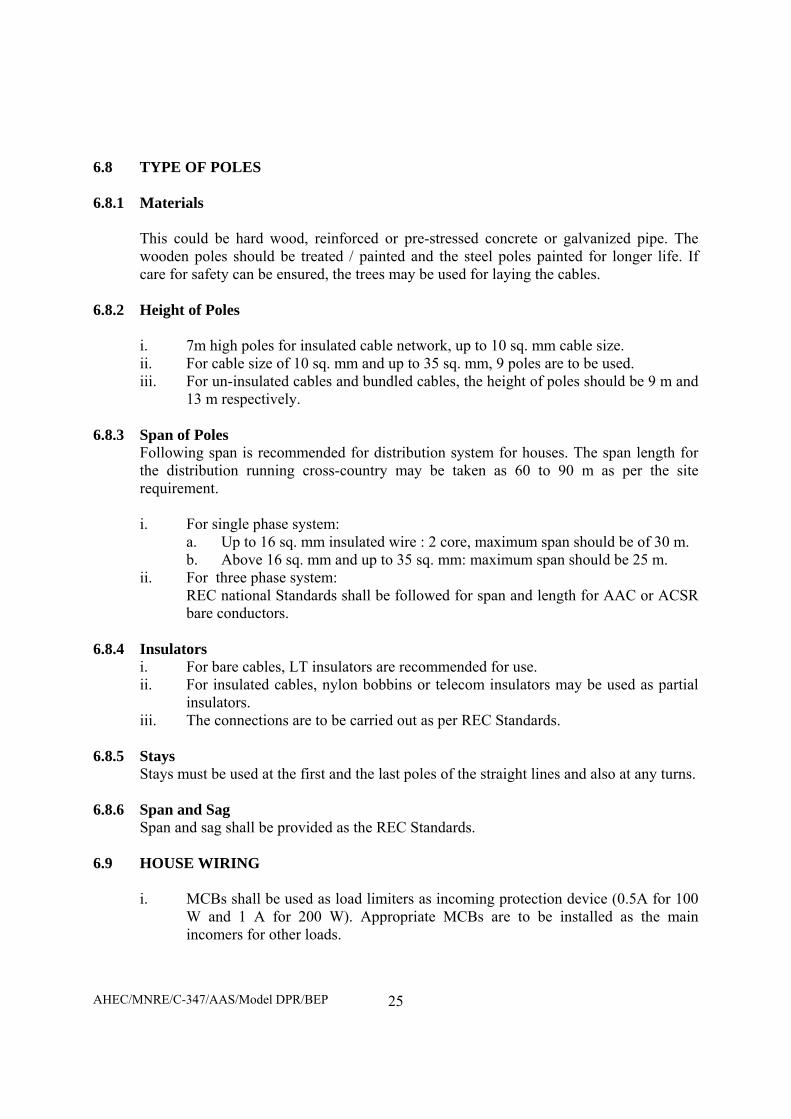
6.8 TYPE OF POLES 6.8.1 Materials
This could be hard wood, reinforced or pre-stressed concrete or galvanized pipe. The wooden poles should be treated / painted and the steel poles painted for longer life. If care for safety can be ensured, the trees may be used for laying the cables.
6.8.2 Height of Poles
i. 7m high poles for insulated cable network, up to 10 sq. mm cable size. ii. For cable size of 10 sq. mm and up to 35 sq. mm, 9 poles are to be used. iii. For un-insulated cables and bundled cables, the height of poles should be 9 m and
13 m respectively. 6.8.3 Span of Poles
Following span is recommended for distribution system for houses. The span length for the distribution running cross-country may be taken as 60 to 90 m as per the site requirement. i. For single phase system:
a. Up to 16 sq. mm insulated wire : 2 core, maximum span should be of 30 m. b. Above 16 sq. mm and up to 35 sq. mm: maximum span should be 25 m.
ii. For three phase system: REC national Standards shall be followed for span and length for AAC or ACSR bare conductors.
6.8.4 Insulators i. For bare cables, LT insulators are recommended for use. ii. For insulated cables, nylon bobbins or telecom insulators may be used as partial
insulators. iii. The connections are to be carried out as per REC Standards.
6.8.5 Stays
Stays must be used at the first and the last poles of the straight lines and also at any turns.
6.8.6 Span and Sag Span and sag shall be provided as the REC Standards.
6.9 HOUSE WIRING
i. MCBs shall be used as load limiters as incoming protection device (0.5A for 100 W and 1 A for 200 W). Appropriate MCBs are to be installed as the main incomers for other loads.
AHEC/MNRE/C-347/AAS/Model DPR/BEP
26
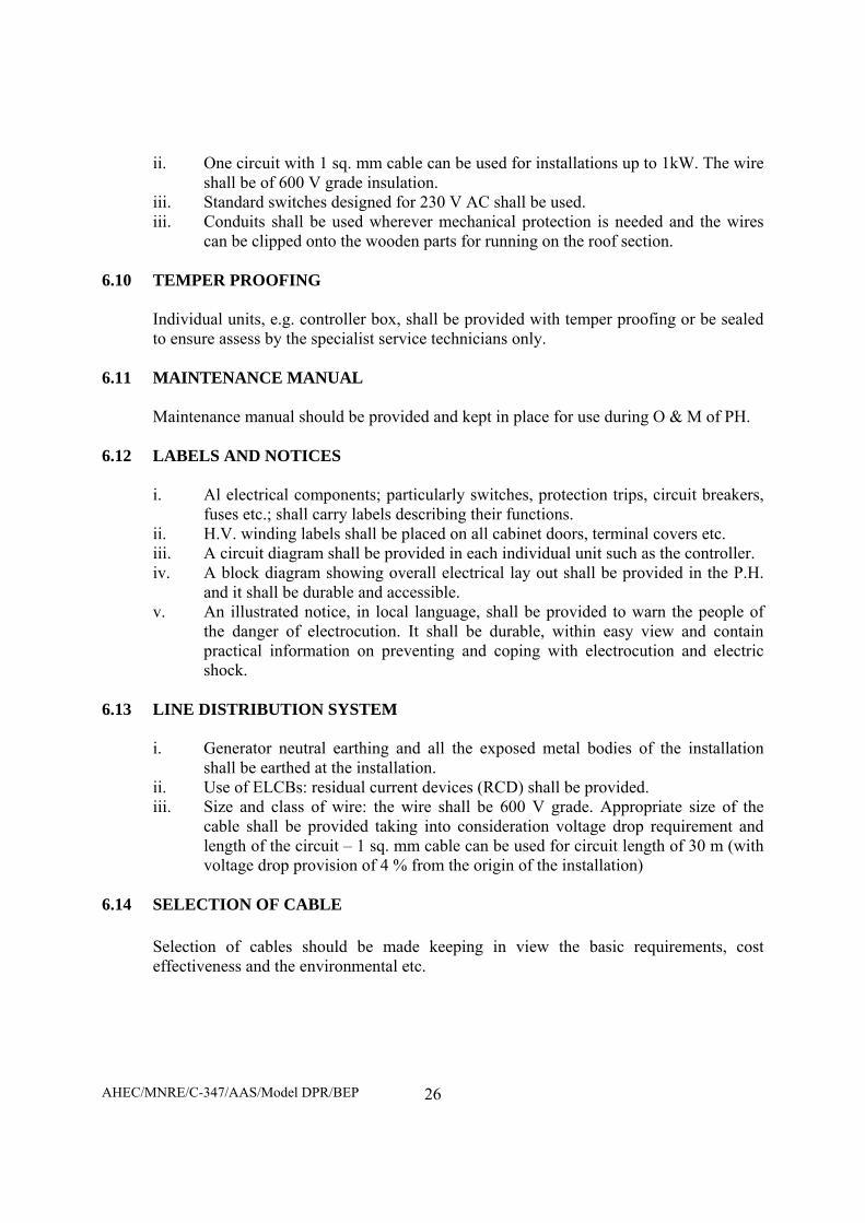
ii. One circuit with 1 sq. mm cable can be used for installations up to 1kW. The wire shall be of 600 V grade insulation.
iii. Standard switches designed for 230 V AC shall be used. iii. Conduits shall be used wherever mechanical protection is needed and the wires
can be clipped onto the wooden parts for running on the roof section.
6.10 TEMPER PROOFING
Individual units, e.g. controller box, shall be provided with temper proofing or be sealed to ensure assess by the specialist service technicians only.
6.11 MAINTENANCE MANUAL
Maintenance manual should be provided and kept in place for use during O & M of PH. 6.12 LABELS AND NOTICES
i. Al electrical components; particularly switches, protection trips, circuit breakers, fuses etc.; shall carry labels describing their functions.
ii. H.V. winding labels shall be placed on all cabinet doors, terminal covers etc. iii. A circuit diagram shall be provided in each individual unit such as the controller. iv. A block diagram showing overall electrical lay out shall be provided in the P.H.
and it shall be durable and accessible. v. An illustrated notice, in local language, shall be provided to warn the people of
the danger of electrocution. It shall be durable, within easy view and contain practical information on preventing and coping with electrocution and electric shock.
6.13 LINE DISTRIBUTION SYSTEM
i. Generator neutral earthing and all the exposed metal bodies of the installation shall be earthed at the installation.
ii. Use of ELCBs: residual current devices (RCD) shall be provided. iii. Size and class of wire: the wire shall be 600 V grade. Appropriate size of the
cable shall be provided taking into consideration voltage drop requirement and length of the circuit – 1 sq. mm cable can be used for circuit length of 30 m (with voltage drop provision of 4 % from the origin of the installation)
6.14 SELECTION OF CABLE
Selection of cables should be made keeping in view the basic requirements, cost effectiveness and the environmental etc.

AHEC/MNRE/C-347/AAS/Model DPR/BEP
27
CHAPTER – 7
TESTING AND COMMISSIONING
7.1 TESTING
Testing of equipment and works are recommended to be carried out as per the relevant I.S./ I.E.C. / any other equivalent Standards/recommendations of the Gasifier Action Research Projects (GARP) under MNRE, Govt. of India.
7.2 COMMISSIONING
After the erection and testing of the equipment/works as per above, commissioning of the plant and works, should be carried out to ensure activities of functional working of the complete system after erection and testing, including tuning or adjustment of the equipment for optimum performance and demonstrating to the Purchaser that the equipment performance meets the requirements of the specifications.
7.3 ACCEPTANCE TESTS AT SITE
It is proposed to carry out tests to obtain the guaranteed out put and efficiency at the site as per the recommendations of the standards.

AHEC/MNRE/C-347/AAS/Model DPR/BEP
28
CHAPTER – 8 PROJECT IMPLIMENTATION STRATAGY
8.1 GENERAL
The project is located in a remote area, where coordination with various organization is essential and hence. A three-tier arrangement is proposed for project implementation.
8.2 ARRANGEMENT
8.2.1 Nodal Agency
UREDA, will be the Nodal Agency, which will have the following functions: i. Obtaining project approval form MNRE, Government of India. ii. Receiving funds from MNRE and disbursement thereof as required. iii. Coordination with the Uttarakhand Forest Department at various levels. iv. Arrangement of land for installation of the Power Plant and for the plantation
of Chir, over a 38 Ha land. v. Preparation of Bid document as per the model specifications to be issued by
the MNRE, floating tender & processing it, placing order and overall supervision of the project implementation.
vi. Overall coordination for project implementation and its Operation and Maintenance.
8.2.2 Uttarakhand Forest Department
Following cooperation and coordination will be sought from Uttarakhand Forest Department: i. Creating awareness and interest amongst the villagers. ii. Motivation and formation of Village Energy Committee (VEC) or motivating
the existing Van Samiti to serve as or make VEC. iii. Granting permission to Van Samiti to use Van Samiti land for plantation of
Chir and/or placement of power plant. iv. Monitoring and coordination as required for project success.
8.2.3 Village Energy Committee
The VEC is proposed to carry out the following functions: i. Motivation and creating interest amongst the villagers for success of the
project. ii. Collection of initial contribution from the villagers towards installation of the
Plant and the System. iii. Collection of monthly payment from the users @ of Rs. 150.00/pm from 5
point load connections and Rs. 100.00 from 3 point load connections or as may be settled by.
iv. Arrangement for plantation for continuous availability of Biomass (in cooperation and coordination with the Uttarakhand Forest Department, VEC and accepted by UREDA.

AHEC/MNRE/C-347/AAS/Model DPR/BEP
29
a. Collection of wood (Shrubs) from the surroundings for bio-gassifers, for the first three years.
b. Preparation of ground, sowing the seeds, watering, fertilizer input, use of pesticide if required etc.
c. Transplantation in the plots, d. Watering, routine after-care. e. Watch and ward. f. Annual cleaning of the area. g. Harvesting by rotation. h. Supplying of the plants logs to the Biomass store shed.
v. Arrangement and supervision of the record. vi. Arrangement / appointment of manager, operators etc. for running of the plant
and system as required. vii. Operation of Bank Account.

AHEC/MNRE/C-347/AAS/Model DPR/BEP
28
CHAPTER – 8 PROJECT IMPLIMENTATION STRATAGY
8.1 GENERAL
The project is located in a remote area, where coordination with various organization is essential and hence. A three-tier arrangement is proposed for project implementation.
8.2 ARRANGEMENT
8.2.1 Nodal Agency
UREDA, will be the Nodal Agency, which will have the following functions: i. Obtaining project approval form MNRE, Government of India. ii. Receiving funds from MNRE and disbursement thereof as required. iii. Coordination with the Uttarakhand Forest Department at various levels. iv. Arrangement of land for installation of the Power Plant and for the plantation
of Chir, over a 38 Ha land. v. Preparation of Bid document as per the model specifications to be issued by
the MNRE, floating tender & processing it, placing order and overall supervision of the project implementation.
vi. Overall coordination for project implementation and its Operation and Maintenance.
8.2.2 Uttarakhand Forest Department
Following cooperation and coordination will be sought from Uttarakhand Forest Department: i. Creating awareness and interest amongst the villagers. ii. Motivation and formation of Village Energy Committee (VEC) or motivating
the existing Van Samiti to serve as or make VEC. iii. Granting permission to Van Samiti to use Van Samiti land for plantation of
Chir and/or placement of power plant. iv. Monitoring and coordination as required for project success.
8.2.3 Village Energy Committee
The VEC is proposed to carry out the following functions: i. Motivation and creating interest amongst the villagers for success of the
project. ii. Collection of initial contribution from the villagers towards installation of the
Plant and the System. iii. Collection of monthly payment from the users @ of Rs. 150.00/pm from 5
point load connections and Rs. 100.00 from 3 point load connections or as may be settled by.
iv. Arrangement for plantation for continuous availability of Biomass (in cooperation and coordination with the Uttarakhand Forest Department, VEC and accepted by UREDA.

AHEC/MNRE/C-347/AAS/Model DPR/BEP
29
a. Collection of wood (Shrubs) from the surroundings for bio-gassifers, for the first three years.
b. Preparation of ground, sowing the seeds, watering, fertilizer input, use of pesticide if required etc.
c. Transplantation in the plots, d. Watering, routine after-care. e. Watch and ward. f. Annual cleaning of the area. g. Harvesting by rotation. h. Supplying of the plants logs to the Biomass store shed.
v. Arrangement and supervision of the record. vi. Arrangement / appointment of manager, operators etc. for running of the plant
and system as required. vii. Operation of Bank Account.
AHEC/MNRE/C-347/AAS/Model DPR/BEP
30
CHAPTER – 9 CONSTRUCTION PROGRAMME
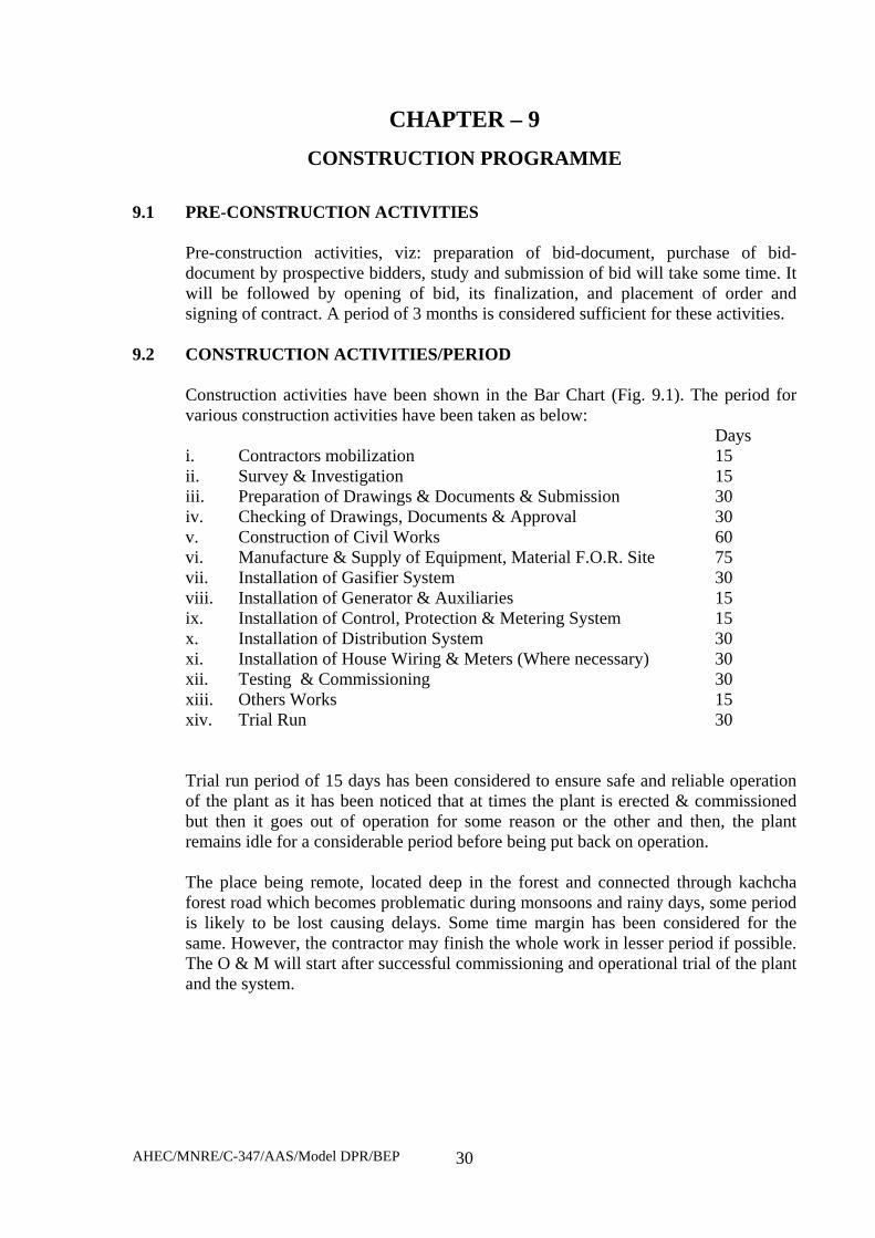
9.1 PRE-CONSTRUCTION ACTIVITIES
Pre-construction activities, viz: preparation of bid-document, purchase of bid-document by prospective bidders, study and submission of bid will take some time. It will be followed by opening of bid, its finalization, and placement of order and signing of contract. A period of 3 months is considered sufficient for these activities.
9.2 CONSTRUCTION ACTIVITIES/PERIOD
Construction activities have been shown in the Bar Chart (Fig. 9.1). The period for various construction activities have been taken as below: Days i. Contractors mobilization 15 ii. Survey & Investigation 15 iii. Preparation of Drawings & Documents & Submission 30 iv. Checking of Drawings, Documents & Approval 30 v. Construction of Civil Works 60 vi. Manufacture & Supply of Equipment, Material F.O.R. Site 75 vii. Installation of Gasifier System 30 viii. Installation of Generator & Auxiliaries 15 ix. Installation of Control, Protection & Metering System 15 x. Installation of Distribution System 30 xi. Installation of House Wiring & Meters (Where necessary) 30 xii. Testing & Commissioning 30 xiii. Others Works 15 xiv. Trial Run 30
Trial run period of 15 days has been considered to ensure safe and reliable operation of the plant as it has been noticed that at times the plant is erected & commissioned but then it goes out of operation for some reason or the other and then, the plant remains idle for a considerable period before being put back on operation. The place being remote, located deep in the forest and connected through kachcha forest road which becomes problematic during monsoons and rainy days, some period is likely to be lost causing delays. Some time margin has been considered for the same. However, the contractor may finish the whole work in lesser period if possible. The O & M will start after successful commissioning and operational trial of the plant and the system.

AHEC/MNRE/C-347/AAS/Model DPR/BEP
31
9.3 BIOMASS SUPPLY FOR THE PLANT The Chir plantation is going to take some time and additional period is required for the growth to the size enough for use. It is proposed that plantation be made immediately after the survey and investigation work is over. During the period of initial run of the plant, and the initial three years period, the supply may be taken from the surroundings and the forest. After three years period the Chir plots will have sufficient quantity of Biomass and it will not be required to be taken from the forest.
9.4 CONTRACTUAL PERIOD OF O & M
The O & M is proposed to be carried out by the contractor for initial 5 years and thereafter the plant will be run by the villagers.

1 2 3 1 2 3 4 5 6 7 8 9 10 11 12 1 2 3 4 5
I PRE-CONTRACT ACTIVITIES1 Preparation of bid document2 NIT & bid Receipt3 Bid Finalization, placing order and signing of contractII CONTRACTUAL ACTIVITIES1 Contractor mobilization2 Survey & investigation3 Preparation of Drawings , Documents & Submission4 Checking of Drawings & approval by Purchaser5 Construction of Civil Works6 Manufacture & supply of Equipment, Material F.O.R. Site7 Construction of E&M works
7.1 Installation of Gasifier System7.2 Installation of Generator & Auxiliaries7.3 Installation of Control, Protection & Metering System7.4 Installation of Distribution System7.5 Installation of House Wiring & meters8 Testing & Commissioning
8.1 Gen. Unit8.2 Other Works8.3 Trial Run9 Plantation of Chire
10 O & M of plants for 5 years
AHEC
/MN
RE/C
-347/AAS/ Model D
PR/BEP 32
O&M PeriodSl. No. YearsMonths
ACTIVITIES
Pre-Construction
Period
Months
Construction Period
FIG. 9.1- BAR CHART : GASIFIER BASED ELECTRIC POWER PROJECT : BHITRI (DISTT. UTTARKASHI, UTTARAKHAND)

AHEC/MNRE/C-347/AAS/Model DPR/BEP
33
CHAPTER -10 ESTIMATE AND FINANCIAL ANALYSIS
10.1 COST OF THE PLANT AND SYSTEM
The cost of the civil works, plant and the system, is shown in Tables – 10.2, 10.3, 10.4, 10.5 & 10.6 the over all cost estimate in Table – 10.1.
TABLE 10.1 : COST ESTIMATE
Sl. No.
Items Cost (Rs. in Lacs)
1 2 3 I Works A Preliminary 0.500 B Land (as per Table 10.2) 0.000
C Civil Works (as per Table 10.3) 33.62
J Power Plant System (as per Table 10.4) 42.34
H Distribution System (as per Table 10.5) 4.10
K Buildings Nil
M Plantation (Subabul Plantation for Biomass) 4.160
O Miscellaneous 0.000
Total I – Woks 84.72
I Establishment (2% of I works excluding Buildings) 1.694
II Suspense Nil
III Receipts and recoveries Nil
IV Indirect Charges (1% of I – works for Audits Accounts) 0.843
Total Project Cost 87.257
AHEC/MNRE/C-347/AAS/Model DPR/BEP
34
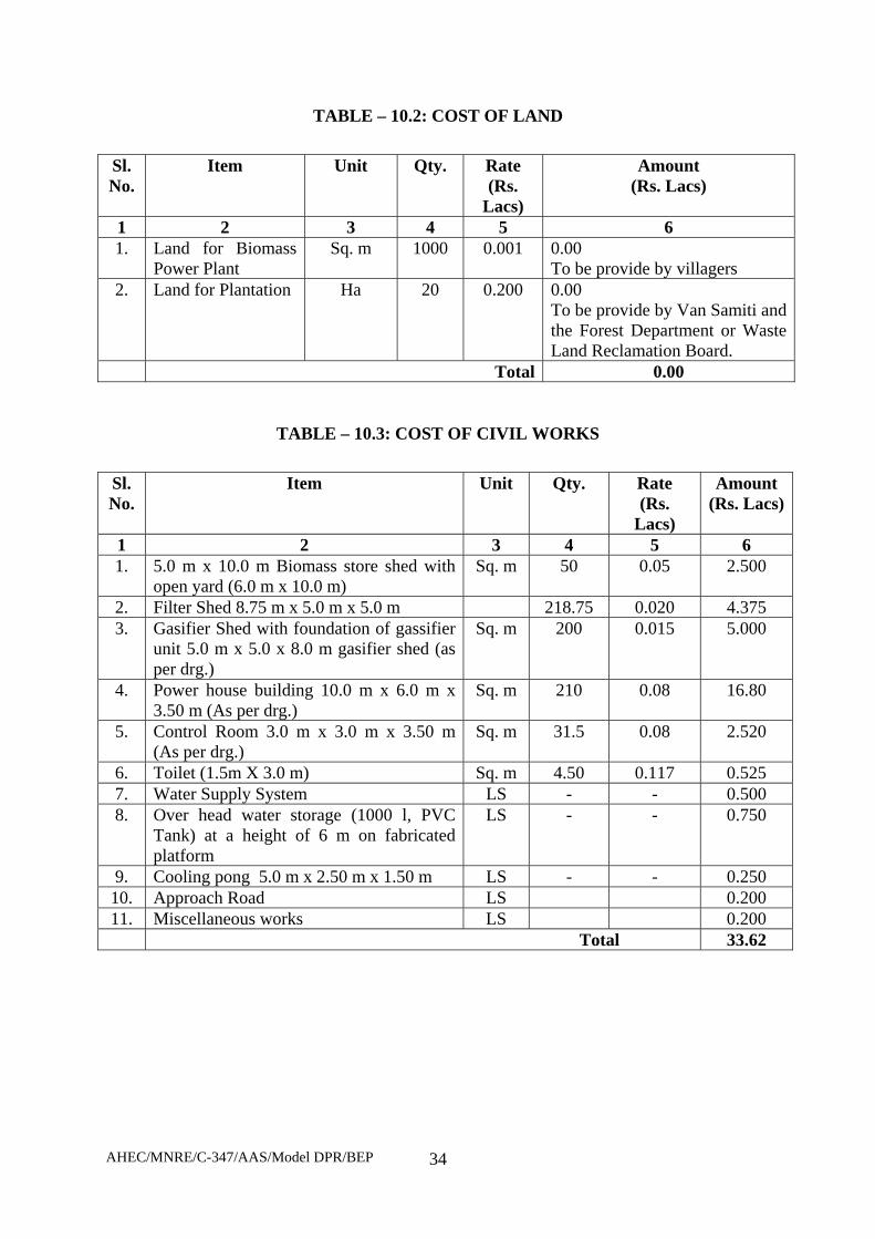
TABLE – 10.2: COST OF LAND Sl. No.
Item Unit Qty. Rate (Rs.
Lacs)
Amount (Rs. Lacs)
1 2 3 4 5 6 1. Land for Biomass
Power Plant Sq. m 1000 0.001 0.00
To be provide by villagers 2. Land for Plantation Ha 20 0.200 0.00
To be provide by Van Samiti and the Forest Department or Waste Land Reclamation Board.
Total 0.00
TABLE – 10.3: COST OF CIVIL WORKS
Sl. No.
Item Unit Qty. Rate (Rs.
Lacs)
Amount (Rs. Lacs)
1 2 3 4 5 6 1. 5.0 m x 10.0 m Biomass store shed with
open yard (6.0 m x 10.0 m) Sq. m 50 0.05 2.500
2. Filter Shed 8.75 m x 5.0 m x 5.0 m 218.75 0.020 4.375 3. Gasifier Shed with foundation of gassifier
unit 5.0 m x 5.0 x 8.0 m gasifier shed (as per drg.)
Sq. m 200 0.015 5.000
4. Power house building 10.0 m x 6.0 m x 3.50 m (As per drg.)
Sq. m 210 0.08 16.80
5. Control Room 3.0 m x 3.0 m x 3.50 m (As per drg.)
Sq. m 31.5 0.08 2.520
6. Toilet (1.5m X 3.0 m) Sq. m 4.50 0.117 0.525 7. Water Supply System LS - - 0.500 8. Over head water storage (1000 l, PVC
Tank) at a height of 6 m on fabricated platform
LS - - 0.750
9. Cooling pong 5.0 m x 2.50 m x 1.50 m LS - - 0.250 10. Approach Road LS 0.200 11. Miscellaneous works LS 0.200
Total 33.62

AHEC/MNRE/C-347/AAS/Model DPR/BEP
35
TABLE – 10.4: COST OF THE PLANT
Sl. No.
Item Unit Qty. Rate (Rs. Lacs)
Amount (Rs. Lacs)
1 2 3 4 5 6 1. Woody biomass gassifier along with 100%
producer gas based engine with generator to give net output of 25 kW along with basic Gassifier accessories & auxiliaries with a double valve assembly for online ash charcoal removal system, Gassifier & engine control panel along with Ampere, volt, frequency and kWh meter as well as load panel for load distribution, and complete gas piping along with valves from gassifier to gas engine.
Set 2 17.20 34.40
2. Wood drying arrangement (Based on Engine Exhaust)
Set 1 0.50 0.500
3. Cooling System Complete pump, piping etc. LS - - 0.500 4. Biomass Cutter No. 1 0.260 0.260 5. Moisture Meter No. 1 0.050 0.050 6. Earthing Kit Set 1 0.150 0.150 7. Auxiliary Genset No. 1 1.650 1.650 8. Skip Charger for Biomass Feeding Set 2 0.750 1.500 9. Chain Pulley Block Set 1 0.330 0.330 10. Miscellaneous LS - 2.000 11. Installation, Commissioning Training of
staff including Service Tax LS - - 1.000
Total 42.34
TABLE – 10.5: COST OF DISTRIBUTION SYSTEM
Sl. No.
Item Unit Qty. Rate (Rs. Lacs)
Amount (Rs. Lacs)
1 2 3 4 5 6 1. L T Distribution Line, km 2.5 1.00 2.50 2. Service Connections Nos. 145 0.01 1.45 3. Street Lights Nos. 15 0.01 0.15 Total 4.10

AHEC/MNRE/C-347/AAS/Model DPR/BEP
36
TABLE – 10.6: COST OF THE BIOMASS DEVELOPMENT PLAN
Sl. No.
Item Unit Qty. Rate (Rs. Lacs)
Amount (Rs. Lacs)
1 2 3 4 5 6 1. Plantation of saplings No. 20 Ha 0.15 3.000 2. Training etc. LS - - 0.660 3. Miscellaneous including Chir Nursery etc. LS - - 0.500 Total 4.160
10.2 FUNDING FOR CONSTRUCTION OF PLANT Rs. Lacs
i. By Grant From MNES : 17.18 ii. Contribution by Villagers @ Rs. 1000/per HH : 1.45 iii. Contribution by Nodal Agency : 68.627
Total 87.257 10.3 FINANCIAL ANALYSIS
The financial analysis has been carried out as per Tables –10.7, 10.8, 10.9 & 10.10. The cost of generation and the results are given below:
10.3.1 Cost of Generation
i. Without Subsidy Rs./kWh a. At 80% LF : 15.792 b. At 60% LF : 21.043
ii. With Subsidy Rs./kWh a. At 80% LF : 13.654
b. At 60% LF : 18.193

AHEC/MNRE/C-347/AAS/Model DPR/BEP
37
TABLE 10.7: COST OF GENERATION WITHOUT SUBSIDY
Sl. No. Items Rs. In Lacs
1 2 3 1 Project Cost 87.257 2 Annual Interest during Construction 5.235
3 Total Project Cost 92.492
4 Annual working expenses (as per table 10.9) 5.041 5 Interest @ 12 % on total project cost 11.099 6 Total annual expenses 16.140 7 Annual generation at power house (Million Units) i. At 80% Load Factor 0.1022 ii. At 60% Load Factor 0.0767 8 Cost of generation per kWh (in Rs) i. At 80 % Load Factor Rs. 15.792 ii. At 60% Load Factor Rs. 21.043
TABLE 10.8 : COST OF GENERATION WITH SUBSIDY
Sl. No. Items Rs. in Lacs
1 2 3 1 Project Cost 87.257 2 Capital Subsidy As per MNES 17.180 3 Balance Project Cost 70.077 4 Annual Interest during Construction 4.204
5 Total Project Cost 74.281
6 Interest @ 12 % on total project cost 8.914 7 Annual working expenses ( as per table 10.9) 5.041 8 Total annual expenses 13.954 9 Annual generation at power house (Million Units) i. At 80% Load Factor 0.1022 ii. At 60% Load Factor 0.0767 10 Cost of generation per kWh (in Rs) i. At 80 % Load Factor Rs. 13.654
ii. At 60% Load Factor Rs. 18.193

AHEC/MNRE/C-347/AAS/Model DPR/BEP
38
TABLE 10.9 : STATEMENT OF YEARLY WORKING EXPENSES Sl. No.
Items Cost (Rs. In Lacs)
1 2 3 1 Operation cost @ 1% of works cost 0.873
2 Maintenance cost of C-works @ 1% 0.336
3 Maintenance of E&M works @ 2% 0.928
4 Annual depreciation charges (as per Table – 10.10) 2.904
Total 5.041
TABLE 10.10: ANNUAL DEPRECIATION OF ASSETS
Sl. No.
Items Life in years
Cost (Rs. Lacs) Rate of Depreciation in %
Depreciation Rs. Lacs
1 2 3 4 5 6 1 Land Infinity 0.00 NIL NIL 2 Civil Works 35 33.62 3.40 1.143 3 Plant & System 35 42.34 3.40 1.440 4 LT Distribution
System 25 4.71 7.84 0.321
Total 2.904
TABLE 10.11 CALCULATION OF SUBSIDY FROM MNES
Sl. No.
Items Cost (Rs. In Lacs)
1 2 3 1 For Biomass Gasifier System 13.50 2 For internal wiring house hold @ Rs. 1500/HH for 145 HH 2.18 3. From regular supply of biomass 1.50 Total 17.18

AHEC/MNRE/C-347/AAS/Model DPR/BEP
39
CHAPTER -11 OPERATION AND MAINTENANCE OF PLANT & SYSTEM
11.1 GENERAL
After the plant and system is tested commissioned and the trial period is over, the operation and maintenance for 5 years period will be the responsibility of the contractor who has supplied, erected tested and commissioned the plant and the system. The contractor may net use100% of his own staff and may require certain number of additional persons for managing O&M under the guidance of his limited staff. The Village Energy Committee (VEC) may arrange for the same from amongst the people of the village, depending on the age, physical so mental health, willingness and the educational qualifications.
11.2 FORMATION OF COMMITTEE FOR SUPERVISION OF O & M
i. Executive Committee The VEC will make an Executive Committee of 5 persons which will supervise and monitor: a. Day to day functioning of the plant & system b. Monitor day to collection of revenue & Expenditure
ii. Staff Following Staff is proposed to be appointed by VEC from amongst the villagers: a. Manager : 1 No. b. Operational Staff : 6 Nos.
iii. Record Keeping Following record is suggested to be kept and maintained by the VEC.
a. Daily wood stock receipt indicating: Sl. No., Date Name of Villager and Quantity (kg)/Rate/Value
b. Stock Register recording : Sl. No., Date, Quantity Received c. Issue Register: Recording Sl. No., Date, Quantity issued and signatures of the
receiver d. Ledger showing daily receipt and issue of wood e. Cash receipt register f. Cash book g. Ledger h. Bank Pass Book & Cheque Book i. General Stock & Issue Register j. Register for Consumables
iv. Supervision & Maintenance of Record a. The manager will keep maintain the record, write cash book & maintain the
account b. VEC executive will check the accounts monthly c. General Meeting of VEC will be held every quarter in which manager will place
before it the records, accounts and status of the plant. d. An annual audit of accounts assets and liabilities will be got carried out by a
competent chartered Account appointed for the purpose by the Nodal Agency Appropriate action will be taken by the Nodal Agency after careful examination.

AHEC/MNRE/C-347/AAS/Model DPR/BEP
40
CHAPTER – 12 ENVIRONMENTAL IMPACT AND BENEFITS
12.1 ENVIRONMENTAL IMPACTS
The non-polluting effluents are discharged from the gassifier, which after settling are reused.
i. Water is re-circulated in closed loop from cooling pond to gassifier scrubber. One has to replenish water pond to compensate evaporation losses and that depends upon the duration of operation in a day, usually, ½ liter of water per unit of electricity generated is to be added as make up water.
ii. Sediment free water can be used for gassifier/cooling pond and hence, it does not require any special water treatment. Whereas, occasionally pH of water is to be rectified.
iii. The other discharges from gasifier are charcoal and ash. Both are of biological nature and biodegradable. 10% dry charcoal can be used again in gasifier while rest can be used as cooking fuel or as an activated carbon in air dryer or as earthing material in electrical towers/connections. Ash can be used as filling materials in large pits or briquettes of ash can be made and sold as fuel cake.
iv. Gas from gasifier is fed directly into engine without any atmospheric discharge while flare is given to occasionally check the quality of gas generated in gasifier and during the stoppage of the system.
v. The major gaseous emission from the power pack is from engine exhaust only. Exhaust from gas engine using producer gas is cleaner than conventional fuel due to absence of sulphur in biomass. The suspended particulate matter in these exhaust gases is always insignificant.
vi. Gasifier being a renewable source of energy equipment, is considered greener technology free from any major environmentally adverse effects.
vii. Gasifier does not have any noise making components except motors, of small capacity. viii. Alternator/engine will also cause some noise but it will be well within the limits. ix. The use of wood in the gassifier for the first three years will damage the vegetation of
the area. Only Putus and Kaknauda shrubs will used as biomass in the gassifier. These shrubs are not considered healthy for the growth of the forest and are removed periodically. Thus the removed of these shrubs will enhance the growth of Sal trees in the forest.
12.2 BENEFITS
i. With the provision of electricity in the village, the life of backward and Harijan Community constituting the population of the village will be uplifted.
ii. Provision of electricity will provide opportunities to the villagers to have cottage industries. This will enhance their economic status.
iii. School going children will have better studying conditions in the homes. iv. With the provision of power in the area, the pressure on wood will reduce considerably. v. With the betterment of lining conditions due to cooperation from the forest department,
the people will have a different attitude towards the forest resources which will ultimately result in saving the forest.

LIST OF PERSONNEL INVOLVEMENT
I. AHEC, IIT, ROORKEE
1. Sri Arun Kumar, Head, AHEC
2. Sri M. K. Singhal, SSO, AHEC
3. Sri Ashuthos Agarwal, JRF, AHEC II. CONSULTANTS
1. Dr. G.C.S. Gaur, Former Faculty Member UOR Roorkee
2. Sri Y. S. Jadaun, Former Chief Engineer (UPSEB) III. ASSISTANTS
1. Sri R. K. Singhal, Technical Assistant
2. Sri Chandarpal Singh, Senior Attendant

Index Map of Village Bhitri
Drg.No C- 361-1
88° 10' 88° 20'
Srinagar
Shimla
Chandigarh
DELHI
JaipurLucknow
BhopalGandhinagar
Patna
Calcutta
Bhubneshwar
Bombay
Panji
Hyderabad
Bangalore
Madras
Trivendram
Gangtok
Itanagar
Guwahati
Shilong
Imphal
JAMMU & KASHMIR
HIMACHALPRADESH
PUNJAB
HARYANA
UTTAR PRADESH
RAJASTHAN
MADHYA PRADESHGUJARAT
BIHAR
ORISSAMAHARASHTRA
WESTBENGAL
ANDHRAPRADESH
KARNATAKA
TAMIL NADU
ARUNACHALPRADESH
ASSAM
MANIPUR
MEGHALAYA
NAGALAND
N E P A LB HUTAN
MYANMAR(BURMA)
GOA
SRI LANKA
Kohima
Aizawl
MIZORAM
KERLA
BANGLA DESH
TRIPURAAgartala
ANDAMAN & NICOBAR ISLANDS
SIKKIM
INDIA
UTTARAKHAND
CHAMOLI
PITHORAGARHALMORA
GARHWAL
CHAMPAWAT
UTTARKASHI
DEHRADUN
HARDWAR
TEHRI GARHWALTEHRI GARHWAL
RUDRAPRAYAG
BAGESHWAR
NAINITAL
UDHAM SINGH NAGARUDHAM SINGH NAGAR
UTTARAKHAND
Project Site