Distribution Transformers General US
16
Answers for energy. Three-Phase Distribution Transformers 50 to 3150 kVA
description
Distribution Transformers General US
Transcript of Distribution Transformers General US
Answers for energy.
Three-Phase Distribution Transformers50 to 3150 kVA
Range covered, standards and specifications
ContentsRange covered, standards and specifi cations 2
Range covered 2
Standards and specifi cations 2
Terms and parameters 3
Core 3
Windings 3
Tappings and tapping range 3
Voltages 3
Currents 3
Operational rating 3
Rated power 3
Rated frequency 4
Rated voltage ratio 4
Losses*) 4
Impedance voltage at rated current 5
Impedance voltage 5
Resistance voltage 5
Reactance voltage 5
Sustained short-circuit current 5
Voltage drop 5
Effi ciency 6
Connections and vector groups 6
Noise level 7
Tolerances 7
60 Hz rated frequency 8
60 Hz supply 8
Design for 60 Hz with 10% higher rated power 8
Single-phase transformers 8
Testing 8
Routine tests 8
Type and special tests 9
Acceptance tests 9
Transformer operation 9
Temperature rise 9
Overload capacity 9
Installation 10
Parallel operation 10
Range coveredThis publication contains general informa-tion on distribution transformers derived from DIN EN 60076 and from IEC Publica-tion 60076. It is applicable to liquid-im-mersed distribution transformers, GEAFOL cast-resin transformers, and transformers with higher ratings. Any differences are expressly indicated.
Standards and specifi cationsThe transformers comply with the relevant VDE regulations for “Transformers and reactors“ and the “Technical conditions of supply for three-phase transformers“ issued by VDEW and ZVEI.
They also satisfy the requirements of the international standards in IEC Publication 60076.
For other specifi cations, enquiries are necessary. Only the US (ANSI/NEMA) and Canadian (CSA) standards differ from IEC to any substantial degree.
*) Information on the evaluation of transformer losses is available on request.
2

CoreThe core carries the magnetic fl ux.
WindingsThe windings carry the magnetomotive force. The winding that takes in power is called the input winding and the one that delivers power is the output winding. The winding designed for the highest rated voltage is called the high-voltage winding and the one for the lowest rated voltage is the low-voltage winding.
Tappings and tapping rangeTappings are additional connections to the windings for altering the voltage ratio.
The tapping range is the difference be-tween the rated voltage and the maximum or minimum adjustable voltage of a wind-ing. The tapping range is specifi ed as a positive and negative percentage of the rated voltage.
VoltagesThe maximum voltage for equipment Um is the maximum rms value of the phase-to-phase voltage for which the insulation of a transformer winding is designed. Standard values for Um in kV are specifi ed in DIN EN 60076-3 and IEC-Publication 60076-3. The Um values are related to values of rated power frequency with-stand voltage (AC, rms) and rated light-ning impulse withstand voltage (LI, peak value; for Um > 1.1 kV only) that identify the insulation level of the particular winding.
The rated voltage (Ur) of a winding is that voltage which must be applied between the line terminals of one winding of a multi-phase transformer, or between the terminals of a single-phase transformer winding, or which occurs there at no-load.
No-load voltageis the voltage between the connecting terminals of an energized transformer on the non-loaded output side.
Full-load voltageis the voltage between the connecting terminals on the output side when the transformer is carrying rated current. It is a function of the power factor cos ϕ.
CurrentsRated current (Ir)is the current fl owing through the line terminal of a winding; it is calculated by dividing the rated power of the winding by its rated voltage and by the correspond-ing phase factor.
No-load current (I0)is the current fl owing through the line terminal of one winding when rated volt-age at rated frequency is applied to it and while the other winding(s) are carrying no load. It is expressed as the mean value of the three phases and as a percentage of the rated current.
Operational ratingThe operational rating is defi ned as opera-tion at rated voltage on the input side, rated current on the output side, and rated frequency.
Rated power (Sr)Rated power is the apparent power that provides a basis for design and testing and that determines a specifi c value of rated current which may fl ow when rated voltage is applied.
Terms and parameters
3
Eddy-current loss, which occurs in addition to hysteresis loss, is due to the time-vari-able magnetic fi eld which induces voltages in the iron. These voltages give rise to currents which circulate in closed circular paths. The relationship I2R between the eddy currents and the resistance of the iron produces the eddy-current loss. How-ever, this loss can be kept to a minimum by using very thin laminations insulated from each other.
Load loss (Pk)is the active power consumed at rated frequency when rated current is fl owing through the line terminal of one winding while the terminals of the other winding are short-circuited. The load loss comprises the heat loss due to the current in the resistance (I2R) and the additional losses caused by eddy currents in the windings and in the structural components.
The load loss is converted to a reference temperature. For oil-immersed transform-ers, this reference temperature is 75°C. For cast-resin transformers, the following values apply:
A = 80°CE = 95°CB = 100°CF = 120°CH = 145°C
If a transformer features different classes, the highest reference temperature for the particular class applies. In a conversion to 75°C, for example, the proportion of the loss corresponding to the DC resistance must be increased in the ratio
225 + 75
225 + ϑc
in the case of aluminum windings, where-as the proportion corresponding to the additional losses must be reduced in the ratio
where ϑc is the temperature at which the losses are measured. For copper windings, the conversion constant “225” in the for-mula must be changed to “235.”
For a load other than the operational rating, the load loss Pk varies in the ratio
225 + ϑc
225 + 75
Load current
Rated current
2
Rated frequency (fr)Rated frequency is the operating frequency for which the transformer is designed.
Rated voltage ratio (nr)The rated voltage ratio is the proportion of the rated voltage of one winding to the lower or equal rated voltage of another winding.
LossesNo-load loss (P0)is the active power consumed when rated voltage at rated frequency is applied to the terminals on one winding while the other winding remains unloaded. It comprises the losses in the core and in the dielectric and the losses arising from the no-load current in the windings. The losses in the dielectric and the windings are generally insignifi cant.
Iron loss, i.e. the majority of the no-load loss, comprises hysteresis loss and eddy-current loss.
Hysteresis loss is due to the movement of the microcrystals which behave as elemen-tary magnets. They provide a resistance to all rotations and alignments and the work expended is generally irreversible; it occurs as a heat loss.
4
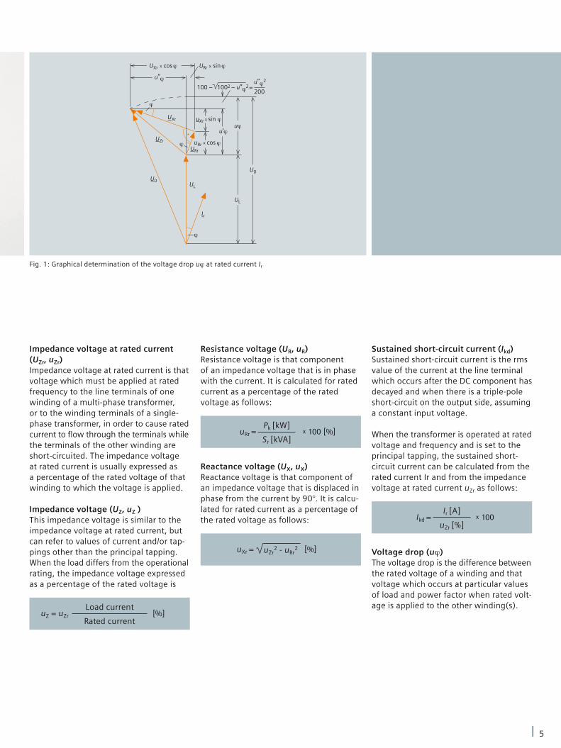
Impedance voltage at rated current(UZr, uZr)Impedance voltage at rated current is that voltage which must be applied at rated frequency to the line terminals of one winding of a multi-phase transformer, or to the winding terminals of a single-phase transformer, in order to cause rated current to fl ow through the terminals while the terminals of the other winding are short-circuited. The impedance voltage at rated current is usually expressed as a percentage of the rated voltage of that winding to which the voltage is applied.
Impedance voltage (UZ, uZ )This impedance voltage is similar to the impedance voltage at rated current, but can refer to values of current and/or tap-pings other than the principal tapping. When the load differs from the operational rating, the impedance voltage expressed as a percentage of the rated voltage is
Load current
Rated currentuZ = uZr [%]
Resistance voltage (UR, uR)Resistance voltage is that component of an impedance voltage that is in phase with the current. It is calculated for rated current as a percentage of the rated voltage as follows:
Reactance voltage (UX, uX)Reactance voltage is that component of an impedance voltage that is displaced in phase from the current by 90°. It is calcu-lated for rated current as a percentage of the rated voltage as follows:
Pk [kW]
Sr [kVA]uRr = x 100 [%]
uZr2 - uRr
2uXr = [%]
Sustained short-circuit current (Ikd)Sustained short-circuit current is the rms value of the current at the line terminal which occurs after the DC component has decayed and when there is a triple-pole short-circuit on the output side, assuming a constant input voltage.
When the transformer is operated at rated voltage and frequency and is set to the principal tapping, the sustained short- circuit current can be calculated from the rated current Ir and from the impedance voltage at rated current uZr as follows:
Voltage drop (uϕ)The voltage drop is the difference between the rated voltage of a winding and that voltage which occurs at particular values of load and power factor when rated volt-age is applied to the other winding(s).
Ir [A]
uZr [%]Ikd = x 100
Fig. 1: Graphical determination of the voltage drop uϕ at rated current Ir
5
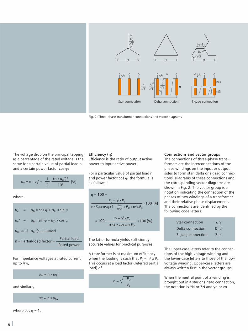
Star connection Delta connection Zigzag connection
n n
n/3
n/3
Effi ciency (η)Effi ciency is the ratio of output active power to input active power.
For a particular value of partial load n and power factor cos ϕ, the formula is as follows:
PO + n2 x Pk
n x Sr x cos ϕ (1 - ) + PO + n2 x Pk
x 100 [%]
η = 100 –
U ϕ100
PO + n2 x Pk
n x Sr x cos ϕ + PO
x 100 [%]≈ 100 -
The latter formula yields suffi ciently accurate values for practical purposes.
A transformer is at maximum effi ciency when the loading is such that P0 = n2 x Pk. This occurs at a load factor (referred partial load) of
PO
Pk
n =
Connections and vector groupsThe connections of three-phase trans-formers are the interconnections of the phase windings on the input or output sides to form star, delta or zigzag connec-tions. Diagrams of these connections and the corresponding vector diagrams are shown in Fig. 2. The vector group is a notation indicating the connection of the phases of two windings of a transformer and their relative phase displacement. The connections are identifi ed by the following code letters:
Star connection Y, y
Delta connection D, d
Zigzag connection Z, z
The upper-case letters refer to the connec-tions of the high-voltage winding and the lower-case letters to those of the low-voltage winding. Upper-case letters are always written fi rst in the vector groups.
When the neutral point of a winding is brought out in a star or zigzag connection, the notation is YN or ZN and yn or zn.
The voltage drop on the principal tapping as a percentage of the rated voltage is the same for a certain value of partial load n and a certain power factor cos ϕ:
1
2uϕ = n x uϕ’ +
(n x uϕ’’)2
102[%]
where
uϕ’ = uRr x cos ϕ + uXr x sin ϕ
uϕ’’ = uRr x sin ϕ + uXr x cos ϕ
uRr and uXr (see above)
n = Partial-load factor = Partial load
Rated power
For impedance voltages at rated current up to 4%,
uϕ ≈ n x uϕ’
and similarly
0 uϕ ≈ n x uRr,
where cos ϕ = 1.
Fig. 2: Three-phase transformer connections and vector diagrams
6
The numeral (0, 5, etc.) in the vector diagram indicates the multiple of 30° by which the low-voltage vector lags counter-clockwise behind the high- voltage vector with the corresponding terminal designation.
Common vector groupsThe most common vector groups are:
Yy0 (Yy6), Yz5 (Yz11), Dy5 (Dy11)
Transformers with these vector groups can have a neutral point brought out on the output side for connection of a neutral conductor in a three-phase distribution system. The vector-group notation is then:
Yyn0 (Yyn6), Yzn5 (Yzn11), Dyn5 (Dyn11)
On transformers of vector groups Yyn0 (Yyn6), the neutral point may only be used for grounding purposes or for a load not exceeding 10% of the rated current. Therefore, the Yyn connection is generally unsuitable for feeding distribution systems having a fourth, neutral conductor. One of the other vector groups must be used. The Yzn and Dyn connections allow the neutral point to carry 100% of the rated current.
In the zigzag connection the current from the line terminal to the neutral terminal always fl ows through two limb windings.
The included angle between the partial voltages of each limb in the three-phase system is 120°.
Therefore, the voltage between the line terminals of the turns (n) comprising a phase is not twice the partial voltage per limb, but only 3 of the partial voltage. This means that the zigzag connection requires
2
3 more winding material than
the star connection.
The delta connection requires 3 times more turns on each limb than the star connection in order to obtain the same voltage.
On the other hand, the conductor cross-section for the delta connection is 1
3 times smaller than for the star
connection.
Noise levelThe noise produced by distribution trans-formers is primarily due to magnetostric-tion in the core laminations. The noise standards for oil-immersed transformers are defi ned in DIN EN 50464 and for cast-resin transformers in DIN EN 50541.
The noise level is taken as the sound power measured according to DIN EN 60076-10.
TolerancesDue to limitations in accuracy of manu-facture, it is necessary to allow tolerances with respect to the technical data. Such tolerances are the permitted deviation of the actual value from the setpoint. They are defi ned in the individual standards and specifi cations and are quoted as a percentage of the setpoint.
7
Single-phase transformers
Testing60 Hz rated frequency60 Hz supplyA transformer designed for a rated fre-quency of 50 Hz can also be operated in a system of identical voltage but with a rated frequency of 60 Hz. The rated power and load loss remain the same, but the no-load loss falls by 20 to 25% and the reactance voltage increases by about 20%.
Design for 60 Hz with 10% higher rated powerIn this case, the load loss, no-load loss and temperature rise are unchanged.Resistance voltage:
uRr
1.1uRr 60 Hz = [%]
Impedance voltage at rated current
uZr 60 Hz =
uRr
1.1[%]
2
+ 1.2 x (uZr2 - uRr
2)
Approximate rated data for a single-phase transformer having a power 2
3 of that of a three-phase transformer listed in the catalog can be ascertained from the catalog data as follows:
P0 1-ph. ≈ 23
P03ph
Pk 1-ph. ≈ 23 Pk3ph
uZ 1-ph. ≈ uZ 3ph
Weight 1-ph. ≈ 0.7 x weight3ph
Length 1-ph. ≈ 0.7 x length3ph
Width 1-ph. ≈ Width3ph
Height 1-ph. ≈ Height3ph
The purpose of testing is to prove confor-mity with the technical data and to ensure that the transformer operates properly. Our transformers are subjected to all the routine tests and type tests specifi ed in the VDE regulations DIN VDE 0532 and IEC Publication 60076 and the respective national regulations listed on page 2.
Routine testsRoutine tests are carried out on all trans-formers and involve the following measure-ments and checks:
Measurement of winding resistance ■
Measurement of voltage ratio and ■
verification of polarity or vector groupMeasurement of impedance voltage ■
Measurement of load loss ■
Measurement of no-load loss and ■
no-load currentInduced overvoltage withstand test ■
Separate-source voltage withstand test ■
Test of freedom from partial discharges ■
(cast-resin transformers)
Test reports are issued.
8
1) 1 K = Sl unit 1°C temperature difference
Transformer operation
Type and special testsType tests are carried out whenever a new range of equipment is introduced or at the customer’s request. They include:
Measurement of temperature rise ■
Lightning impulse test ■
Measurement of noise level ■
Short-circuit test ■
Test of climatic, fi re and environmental ■
class
Acceptance testsThese tests are a repetition of the routine and type tests and therefore involve addi-tional work and expense.
Temperature riseTransformers are designed so that the temperature rise specifi ed by the regula-tions is not exceeded during operation under rated conditions. The temperature rise of the winding and that of the cool-ing and insulating liquid (in the case of liquid-immersed transformers) is the differ-ence in temperature between the winding and the ambient air. The regulations specify maximum temperatures as well as average daily and annual temperatures for the ambient air.
For the winding, the mean temperature rise determined through resistance in relation to temperature applies.
The maximum temperature rise of the cooling and insulating liquid is obtained by measurement at the thermometer pocket. On our transformers, it is usually less than the permitted temperature rise of the insulating liquid.
Overload capacityOverloading of a transformer is permitted by IEC regulations, provided that the specifi ed coolant temperatures are not exceeded. The temperature rise fi gures may be increased by the same amount. The corresponding increase in power can be determined for our transformers by a rule-of-thumb method as follows: 1% per 1 K1) below the cooling-air temperature for oil-immersed transformers, 0.6% per 1 K for GEAFOL transformers.
Overloading without exceeding the per-mitted winding temperature rise is also permissible for short periods, provided that the preceding continuous load has been below the rated power level, and thus the permitted temperature rise fi gure has not been attained. Additional overload capacity (as a function of power up to about 50%) can be obtained by forced cooling of the transformers with fans (it can also be performed subsequently if necessary).
9
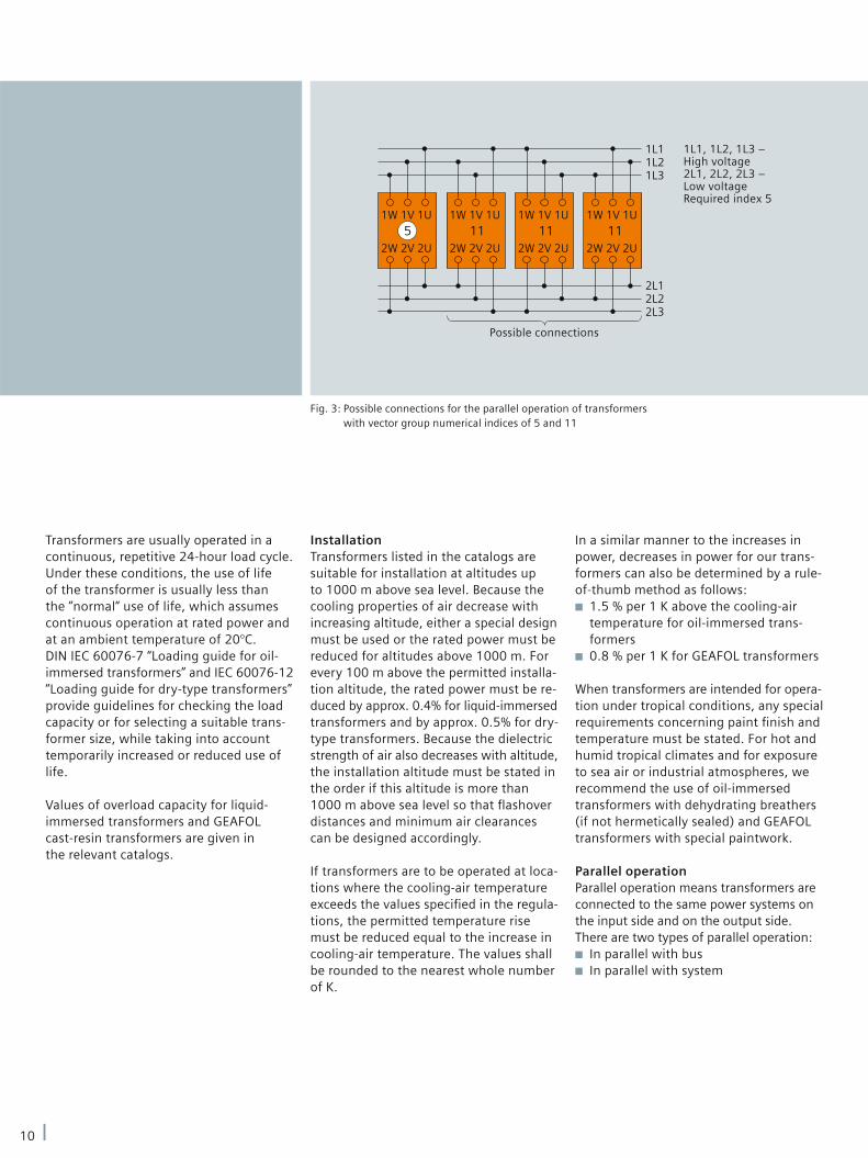
1L1, 1L2, 1L3 –High voltage2L1, 2L2, 2L3 –Low voltageRequired index 5
Possible connections
InstallationTransformers listed in the catalogs are suitable for installation at altitudes up to 1000 m above sea level. Because the cooling properties of air decrease with increasing altitude, either a special design must be used or the rated power must be reduced for altitudes above 1000 m. For every 100 m above the permitted installa-tion altitude, the rated power must be re-duced by approx. 0.4% for liquid-immersed transformers and by approx. 0.5% for dry-type transformers. Because the dielectric strength of air also decreases with altitude, the installation altitude must be stated in the order if this altitude is more than 1000 m above sea level so that fl ashover distances and minimum air clearances can be designed accordingly.
If transformers are to be operated at loca-tions where the cooling-air temperature exceeds the values specifi ed in the regula-tions, the permitted temperature rise must be reduced equal to the increase in cooling-air temperature. The values shall be rounded to the nearest whole number of K.
In a similar manner to the increases in power, decreases in power for our trans-formers can also be determined by a rule-of-thumb method as follows:
1.5 % per 1 K above the cooling-air ■
temperature for oil-immersed trans-formers0.8 % per 1 K for GEAFOL transformers ■
When transformers are intended for opera-tion under tropical conditions, any special requirements concerning paint fi nish and temperature must be stated. For hot and humid tropical climates and for exposure to sea air or industrial atmospheres, we recommend the use of oil-immersed transformers with dehydrating breathers (if not hermetically sealed) and GEAFOL transformers with special paintwork.
Parallel operationParallel operation means transformers are connected to the same power systems on the input side and on the output side. There are two types of parallel operation:
In parallel with bus ■
In parallel with system ■
Transformers are usually operated in a continuous, repetitive 24-hour load cycle. Under these conditions, the use of life of the transformer is usually less than the ”normal“ use of life, which assumes continuous operation at rated power and at an ambient temperature of 20°C. DIN IEC 60076-7 “Loading guide for oil-immersed transformers” and IEC 60076-12 “Loading guide for dry-type transformers” provide guidelines for checking the load capacity or for selecting a suitable trans-former size, while taking into account temporarily increased or reduced use of life.
Values of overload capacity for liquid- immersed transformers and GEAFOL cast-resin transformers are given in the relevant catalogs.
Fig. 3: Possible connections for the parallel operation of transformers with vector group numerical indices of 5 and 11
10
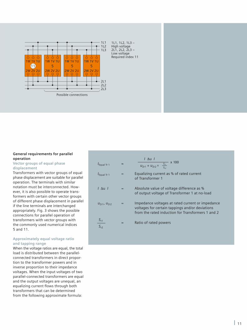
1L1, 1L2, 1L3 –High voltage2L1, 2L2, 2L3 –Low voltageRequired index 11
Possible connections
General requirements for parallel operationVector groups of equal phase displacementTransformers with vector groups of equal phase displacement are suitable for parallel operation. The terminals with similar notation must be interconnected. How-ever, it is also possible to operate trans-formers with certain other vector groups of different phase displacement in parallel if the line terminals are interchanged appropriately. Fig. 3 shows the possible connections for parallel operation of transformers with vector groups with the commonly used numerical indices 5 and 11.
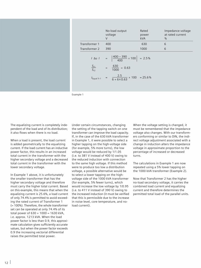
Approximately equal voltage ratio and tapping rangeWhen the voltage ratios are equal, the total load is distributed between the parallel-connected transformers in direct propor-tion to the transformer powers and in inverse proportion to their impedance voltages. When the input voltages of two parallel-connected transformers are equal and the output voltages are unequal, an equalizing current fl ows through both transformers that can be determined from the following approximate formula:
IEqual Tr 1 ≈
IEqual Tr 1 = Equalizing current as % of rated current of Transformer 1
I Δu I = Absolute value of voltage difference as % of output voltage of Transformer 1 at no-load
uZr1, uZr2 = Impedance voltages at rated current or impedance voltages for certain tappings and/or deviations from the rated induction for Transformers 1 and 2
= Ratio of rated powers
I Δu I
uZr1 + uZr2 x x 100Sr1
Sr2
Sr1
Sr2
11
No-load output voltage V
IEqual Tr 1
Transformer 1
Transformer 2
Rated powerkVA
Impedance voltage at rated current%
The equalizing current is completely inde-pendent of the load and of its distribution; it also fl ows when there is no load.
When a load is present, the load current is added geometrically to the equalizing current. If the load current has an inductive power factor, this results in an increased total current in the transformer with the higher secondary voltage and a decreased total current in the transformer with the lower secondary voltage.
In Example 1 above, it is unfortunately the smaller transformer that has the higher secondary voltage and therefore must carry the higher total current. Based on this example, this means that when the equalizing current is 25.6%, a load current of only 74.4% is permitted to avoid exceed-ing the rated current of Transformer 1 (= 100%). Therefore, the whole transformer set can be operated at only 74.4% of its total power of 630 + 1000 = 1630 kVA, i.e. approx. 1213 kVA. When the load power factor is less than 0.9, this approxi-mate calculation gives suffi ciently accurate values, but when the power factor exceeds 0.9 the increasing vectorial differential raises the permitted total power.
Under certain circumstances, changing the setting of the tapping switch on one transformer can improve the load capacity. If, in the case of the 630 kVA transformer in Example 1, it were possible to select a higher tapping on the high-voltage side (for example, 5% more turns), the low voltage would be reduced by 1/1.05 (i.e. to 381 V instead of 400 V) owing to the reduced induction with connection to the same high voltage. If this method were to produce too low a distribution voltage, a possible alternative would be to select a lower tapping on the high-voltage side of the 1000 kVA transformer (for example, 5% fewer turns), which would increase the low voltage by 1/0.95 (i.e. to 411 V instead of 390 V) owing to the increased induction (it must be verifi ed that this is permissible due to the increase in noise level, core temperature, and no-load current).
When the voltage setting is changed, it must be remembered that the impedance voltage also changes. With our transform-ers conforming or similar to DIN, the indi-rect voltage adjustment associated with a change in induction alters the impedance voltage in approximate proportion to the percentage of increased or decreased turns.
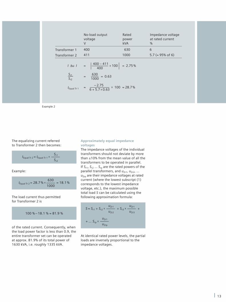
The calculations in Example 1 are now repeated using a 5% lower tapping on the 1000 kVA transformer (Example 2).
Now that Transformer 2 has the higher no-load secondary voltage, it carries the combined load current and equalizing current and therefore determines the permitted total load of the parallel units.
Example 1
12
No-load output voltage V
Transformer 1
Transformer 2
Rated powerkVA
Impedance voltage at rated current%
IEqual Tr 1
The equalizing current referred to Transformer 2 then becomes:
Sr1
Sr2
IEqual Tr 2 = IEqual Tr 1 x
Example:
630
1000IEqual Tr 2 = 28.7 % x = 18.1 %
The load current thus permitted for Transformer 2 is
100 % – 18.1 % ≈ 81.9 %
of the rated current. Consequently, when the load power factor is less than 0.9, the entire transformer set can be operated at approx. 81.9% of its total power of 1630 kVA, i.e. roughly 1335 kVA.
Approximately equal impedance voltagesThe impedance voltages of the individual transformers should not deviate by more than ±10% from the mean value of all the transformers to be operated in parallel. If Sr1, Sr2 … Srp are the rated powers of the parallel transformers, and uZr1, uZr2, … uZrp are their impedance voltages at rated current (where the lowest subscript (1) corresponds to the lowest impedance voltage, etc.), the maximum possible total load S can be calculated using the following approximation formula:
uZr1
uZr2
S ≈ Sr1 + Sr2 x + Sr3 x uZr1
uZr3
+
+ … Srp x uZr1
uZrp
At identical rated power levels, the partial loads are inversely proportional to the impedance voltages.
Example 2
13
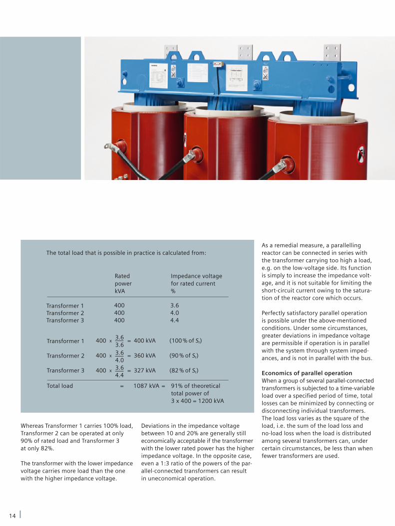
Deviations in the impedance voltage between 10 and 20% are generally still economically acceptable if the transformer with the lower rated power has the higher impedance voltage. In the opposite case, even a 1:3 ratio of the powers of the par-allel-connected transformers can result in uneconomical operation.
As a remedial measure, a parallelling reactor can be connected in series with the transformer carrying too high a load, e.g. on the low-voltage side. Its function is simply to increase the impedance volt-age, and it is not suitable for limiting the short-circuit current owing to the satura-tion of the reactor core which occurs.
Perfectly satisfactory parallel operation is possible under the above-mentioned conditions. Under some circumstances, greater deviations in impedance voltage are permissible if operation is in parallel with the system through system imped-ances, and is not in parallel with the bus.
Economics of parallel operationWhen a group of several parallel-connected transformers is subjected to a time-variable load over a specifi ed period of time, total losses can be minimized by connecting or disconnecting individual transformers. The load loss varies as the square of the load, i.e. the sum of the load loss and no-load loss when the load is distributed among several transformers can, under certain circumstances, be less than when fewer transformers are used.
Whereas Transformer 1 carries 100% load, Transformer 2 can be operated at only 90% of rated load and Transformer 3 at only 82%.
The transformer with the lower impedance voltage carries more load than the one with the higher impedance voltage.
The total load that is possible in practice is calculated from:
Transformer 1Transformer 2Transformer 3
Transformer 1
Transformer 2
Transformer 3
Rated powerkVA
Impedance voltage for rated current%
Total load = 1087 kVA = 91% of theoretical total power of 3 x 400 = 1200 kVA
14

1 Transformer2 Transformers3 Transformers
18,000
14,000
10,000
6,000
2,000
Load (kVA)
3 Transformers
2 Transformers
1 Transformer
Fig. 4: Curves of total losses of parallel-connected 400-kVA transformers
In order to avoid a complicated comparison of the losses of the parallel-connected transformers, it is possible to calculate the partial load at which the switching-in of another identical transformer (the pth trans-former) becomes economical as follows:
Partial load
Rated powerPartial-load factor n =
Power of the group
SGroup = n x Sr
Sr = Rated power of the individual transformer
The partial-load factor for the economical switching-in of another identical trans-former (the pth transformer) can be calculated using the following formula:
p x (p-1) x PO
Pk
n =
p = Number of transformers to be connected in parallel
Sample calculation for three identical transformers to be connected in parallel:
Rated data
Rated power Sr 400 kVA
No-load ratio ür 10/0.4 kV
Vector group Dyn5
Rated frequency fr 50 Hz
No-load losses P0 930 W
Load losses Pk 4600 W
Impedance voltage
at rated current uZr 4%
with p = 2 p = 3
SGroup = 0.64 x 400 = 256 kVA SGroup = 1.10 x 400 = 440 kVA
2 x 1 x 930
4600n = = 0.64
3 x 2 x 930
4600n = = 1.10
Therefore, it is most economical to switch in the second transformer at 256 kVA and the third at 440 kVA, a fi gure precisely 10% above the rated power of one trans-former. This can also be seen in Fig. 4.
15

www.siemens.com/energy
Published by and copyright © 2010:Siemens AGEnergy SectorFreyeslebenstrasse 191058 Erlangen, Germany
Transformatorenwerk KirchheimPower Transmission DivisionTransformersHegelstraße 2073230 Kirchheim/Teck, GermanyPhone: +49 (0) 7021 508-0Fax: +49 (0) 7021 508-495
For more information, please contact our Customer Support Center.Phone: +49 180/524 70 00Fax: +49 180/524 24 71(Charges depending on provider)E-mail: [email protected]
Power Transmission Division Order No. E50001-G640-A149-X-4A00Printed in GermanyDispo 19201, c4bs No. 7481TH 101-100167 470940 WS 05101.0
Printed on elementary chlorine-free bleached paper.
All rights reserved.Trademarks mentioned in this document are the property of Siemens AG, its affiliates, or their respective owners.
Subject to change without prior notice.The information in this document contains generaldescriptions of the technical options available, whichmay not apply in all cases. The required technicaloptions should therefore be specified in the contract.