Distributed On-demand Routing for LEO Satellite...
27
Distributed On-demand Routing for LEO Satellite Systems E. Papapetrou, S. Karapantazis, F.-N. Pavlidou Abstract Notwithstanding the limited commercial success of the first narrowband Low Earth Orbit (LEO) satellite systems, the interest of the scientific community in this type of systems has been revived on the basis of the current trend toward the migration to all IP-based services. LEO systems can play a pivotal role in providing services to areas where there is no substantial terrestrial infrastructure. Above all, LEO satellite systems can be used as backbone networks to interconnect autonomous systems worldwide. Such an approach provides flexibility in managing the resulting integrated network infrastructure and supporting innovative applications. In this context, routing data from the source all the way to the destination constitutes a daunting challenge. In this paper, a location-assisted on-demand routing (LAOR) protocol is proposed and evaluated. The proposed protocol introduces for the first time in satellite systems the concept of on-demand routing. However, its implementation is tailored to the requirements imposed by the characteristics of the topology of LEO satellite systems. The performance of the LAOR protocol is assessed for different link-cost metrics and compared to the one of centralized routing protocols proposed in the literature so far. Simulation studies further document and confirm the positive characteristics of the proposed protocol. Key words: routing, on-demand, satellite, Low Earth Orbit 1. Introduction Ubiquitous and pervasive communication is one of the major challenges that state-of-the-art networking faces nowadays. Satellite systems have always been the prevailing candidate for realizing the vision of anywhere, anytime connectivity on account of their inherent ability to provide global coverage. In fact, satellite networks have been used for years for a wide spectrum of services such as remote sensing, telephony services and television broadcasts [1]. In the past few years of the previous decade, the attention of the telecommunications community was drawn toward systems deployed at altitudes between 500 km and 1500 km, which are termed low earth orbit (LEO) satel- Preprint submitted to Elsevier
Transcript of Distributed On-demand Routing for LEO Satellite...
Distributed On-demand Routing for LEO Satellite
Systems
E. Papapetrou, S. Karapantazis, F.-N. Pavlidou
Abstract
Notwithstanding the limited commercial success of the flrst narrowband Low Earth Orbit (LEO)
satellite systems, the interest of the scientiflc community in this type of systems has been
revived on the basis of the current trend toward the migration to all IP-based services. LEO
systems can play a pivotal role in providing services to areas where there is no substantial
terrestrial infrastructure. Above all, LEO satellite systems can be used as backbone networks to
interconnect autonomous systems worldwide. Such an approach provides °exibility in managing
the resulting integrated network infrastructure and supporting innovative applications. In this
context, routing data from the source all the way to the destination constitutes a daunting
challenge. In this paper, a location-assisted on-demand routing (LAOR) protocol is proposed and
evaluated. The proposed protocol introduces for the flrst time in satellite systems the concept
of on-demand routing. However, its implementation is tailored to the requirements imposed
by the characteristics of the topology of LEO satellite systems. The performance of the LAOR
protocol is assessed for difierent link-cost metrics and compared to the one of centralized routing
protocols proposed in the literature so far. Simulation studies further document and conflrm the
positive characteristics of the proposed protocol.
Key words: routing, on-demand, satellite, Low Earth Orbit
1. Introduction
Ubiquitous and pervasive communication is one of the major challenges that state-of-the-art networking faces
nowadays. Satellite systems have always been the prevailing candidate for realizing the vision of anywhere, anytime
connectivity on account of their inherent ability to provide global coverage. In fact, satellite networks have been
used for years for a wide spectrum of services such as remote sensing, telephony services and television broadcasts
[1]. In the past few years of the previous decade, the attention of the telecommunications community was drawn
toward systems deployed at altitudes between 500 km and 1500 km, which are termed low earth orbit (LEO) satel-
Preprint submitted to Elsevier

lite systems [2]. LEO satellite systems provide low propagation delay which enables real-time communications as
well as higher throughput compared to geostationary links. Furthermore, the low satellite altitude relaxes power
requirements, allowing mobility and providing high data rates. Despite the advantages of LEO systems, the com-
mercial success of the two operating narrowband LEO networks was limited, since at that time the networking
market witnessed a worldwide proliferation of terrestrial infrastructure ofiering similar services. Satellite systems
failed to compete with terrestrial networks in providing cost-efiective broadband connectivity and as a result the
interest in non-GEO systems temporarily dwindled away. Over the last years this interest has been renewed on the
basis that satellite systems should augment the operation of terrestrial networks rather than compete with them
[3]. According to this concept, LEO constellations can be employed to unify far-°ung groups of people and provide
high-quality telecommunication services to areas where there is no substantial terrestrial infrastructure. Moreover,
other application scenarios include situations where terrestrial infrastructure is out of order, for instance during
emergency situations, or not adequate owing to temporarily increased communications demands.
Furthermore, the current trend toward the migration to all IP-based services opens new opportunities to LEO
satellite systems [4]. The unprecedented growth of the Internet, along with the proliferation of multimedia worksta-
tions, has spurred and prompted the development of innovative applications with high bandwidth and low end-to-end
delay requirements. In addition, providing broadband communication services in world-wide scale through terres-
trial infrastructures is not a trivial task. It involves the integration of a plethora of networking technologies and the
coordinated operation of numerous autonomous systems. Besides interoperability issues, the greatest disadvantage
is the lack of °exibility in designing and implementing network-wide management decisions to support new services
and applications. The Internet represents such an example. The deployment of IPv6, which relies on the consent of
network operators worldwide, has never been completed. For the same reasons providing QoS through a suitable
routing algorithm is not feasible. Another typical example is the advent of overlay networks. The basic concept is
to provide connectivity at the transport layer to support network-wide, °exible applications. It is apparent that
network-wide coordination and management is essential for providing diverse and quality services. To this end,
LEO satellite networks may play a pivotal role by providing backbone connectivity to terrestrial systems. The
limited number of satellites needed allows the provision of high-quality worldwide connections. Furthermore, the
management of such networks provides °exibility in adapting the network to new user demands and applications.
In the aforementioned context, routing data from the source to the destination, through the LEO network,
constitutes a daunting challenge. Many of the proposed LEO constellations make use of inter-satellite links (ISLs)
to provide direct connectivity between adjacent satellites. The resulting celestial network resembles a mesh and
represents the most interesting architecture from a routing viewpoint, thus all the studies in this fleld focused
on constellations with ISLs. In addition to the resulting highly connected graph, other characteristics such as the
network size, the discontinuous operation of ISLs, the propagation delay and the unbalanced loading of the celestial
network, pose strict requirements to the design of e–cient routing algorithms. Most of the proposed approaches so
far involve a centralized scheme for calculating paths for all origin/destination pairs. In addition, they take advantage
of the deterministic dynamics of this network topology in order to divide the system period into a number of time
intervals during which the topology of the network is flxed.
In this paper we propose a location-assisted on-demand routing (LAOR) protocol for LEO satellite IP networks
2
that employ ISLs. The protocol introduces the well-known concept of on-demand routing into satellite networks.
LAOR can be viewed as a variant of the ad-hoc on-demand distance vector (AODV) routing algorithm [5], tailored
to the requirements imposed by the characteristics of LEO networks’ topology. The prime aim of the LAOR protocol
is to minimize end-to-end delay and delay jitter, while keeping signaling overhead to a minimum at the same time.
Toward this end, the path discovery process is invoked independently for each individual origin/destination pair.
However, our algorithm capitalizes upon the deterministic characteristics of the LEO mesh architecture in order
to restrict the number of satellites that are °ooded with route request messages. The performance of the proposed
protocol is evaluated for difierent link-cost metrics and compared to the performance of proposed centralized routing
protocols. Simulation studies further document and conflrm the positive characteristics of the proposed protocol.
The remainder of the paper is structured as follows. In section 2 the related work is presented and the motivation
for the new protocol is discussed. Then, the LAOR protocol is delineated in section 3, highlighting its main difierences
with centralized, proactive routing schemes. Section 4 is devoted to the description of the simulation model used for
the assessment of the new protocol. In section 5 simulation results are presented and discussed, while concluding
remarks are drawn in section 6.
2. Related Work and Motivation
The performance of routing protocols depends on their perception of the network status. The state of nodes and
related links should be frequently collected in order to depict the current network status. Routing relies heavily
on the frequency and accuracy of this procedure which in turn depends on the rate that the collected information
varies. The common approach in the literature as yet has been to capitalize upon network dynamics and periodically
evaluate the propagation delay in each ISL, considering this as the metric to be minimized in the route calculation
process. In [6] a centralized routing scheme geared toward ATM-based LEO/MEO networks was proposed, which
relies on the Dijkstra shortest path algorithm to compute the optimal path for any pair of satellites. Werner
extended that scheme by introducing a heuristic metric for calculating the cost of each ISL in [7]. The proposed
metric evaluates the permanence of ISLs as well as the expected incoming tra–c based on the link’s location
with regard to the Earth’s surface. A similar approach is represented by the Probabilistic Routing Protocol [8].
This protocol takes into account the propagation delay and connectivity of ISLs in order to minimize the number
of re-routing attempts that occur due to the fact that one of the ISLs that make up the path is switched ofi.
The methodology described so far, provides acceptable implementation complexity considering that the satellites’
movement is deterministic. However, such schemes are not designed or not supposed to take into account tra–c
related metrics such as queueing delay.
Later research laid emphasis on this shortcoming, nevertheless, the periodic nature of updates has been main-
tained. Mohorcic et al proposed a centralized routing protocol that is also based on the Dijkstra algorithm in
[9],[10]. That protocol makes use of a cost metric that takes into account both propagation and queuing delay
measurements and combines them with appropriate weighting factors. A similar approach was adopted by Akyildiz
et al when dealing with the issue of routing in multilayered satellite IP networks in [11]. Another useful approach
presented in [12] treated the issues of both topological design and routing in LEO satellite systems using a flnite
3

state automaton (FSA). A modifled Flow Deviation algorithm for inclined Walker delta LEO satellite systems was
developed in [13]. The main function of the Flow Deviation algorithm is to split tra–c into many difierent paths.
However, in order to reduce the algorithm’s complexity and make it applicable to LEO networks, the modifled
algorithm uses a limited number of paths. That algorithm was further amended in [14] in order to be functional in
Walker star LEO constellations, which are characterized by the discontinuous operation of ISLs.
All the aforementioned algorithms use proactive route calculation which involves high overhead and is also
deeply afiected by the network’s size and connectivity. All the proposed systems so far involve a celestial network
consisting of some tens up to some hundreds of satellites, which gives rise to justifled skepticism about the feasibility
and overhead requirements of routing protocols. Moreover, bearing in mind the connectivity of adjacent satellites
(normally 4-8 ISLs), the task of keeping the related overhead low can be questioned. The overall overhead is also
subject to the frequency of updates. The latter depends on the rate of information exchanged by the protocol.
For example, for a tra–c-adaptive protocol the route table update interval should be chosen to capture tra–c
variations, which results in increased overhead. In the case of LEO satellite systems even the propagation delay
of each link changes rapidly. Although update intervals of about 30 sec (adopted so far in the literature) provide
satisfactory adaptation to propagation delay variations, when adaptivity to tra–c related metrics (i.e., queueing
delay) is required, periodic updates may result in high overhead. In fact, thus far no study has evaluated the related
overhead of proposed routing algorithms in satellite systems.
Another major disadvantage of the proposed algorithms stems from their centralized implementation. Shouldering
the burden of route calculation to a single point brings about some signiflcant disadvantages such as reliability. In
addition, the delay involved in collecting routing information and distributing routing decisions degrades network
performance. Ekici et al [15] proposed a distributed routing scheme that routes each IP packet independently and
induces no signaling overhead. That algorithm evaluates only propagation delay. Nonetheless, to avoid congested
links, the algorithm introduces a queue size threshold over which packets are deviated to less congested routes.
The key concept of the strategy proposed in this work is to obviate the need for periodic route computation in
highly connected and of great size networks such as LEO constellations, in order to minimize routing overhead.
Furthermore, proactive methods have an impact on algorithm accuracy, since they can only provide an estimation of
the optimal path for each source-destination pair during a speciflc interval. This estimation relies on the information
about the network state collected in the last computation. The more frequent network state changes are, the poorer
the performance of the routing algorithm is.
Therefore in this paper we propose the use of on-demand routing in satellite networks. By performing on-demand
path computation the proposed algorithm manages to capture the path state at the time needed. Another obser-
vation supporting the on-demand approach refers to the non-uniform loading of the celestial network as a result of
population dispersion, economic °ourish and technology penetration diversity. Consequently routing requirements
vary across the entire network, rendering the pre-computation of routes for all source/destination pairs ine–cient.
The key concept lies in allowing the routing algorithm to adapt to routing requests. On-demand routing is well-
known in other types of networks, such as ad-hoc networks [16], however its suitability and applicability to satellite
networks has never been addressed. The major drawback of such an approach is the °ood-based mechanism used
for discovering paths. The high connectivity degree of satellites may well lead to severe overhead requirements.
4
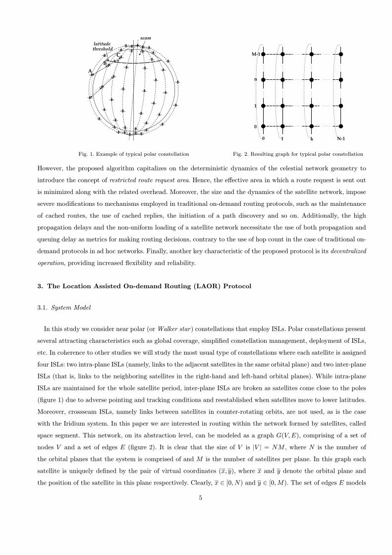
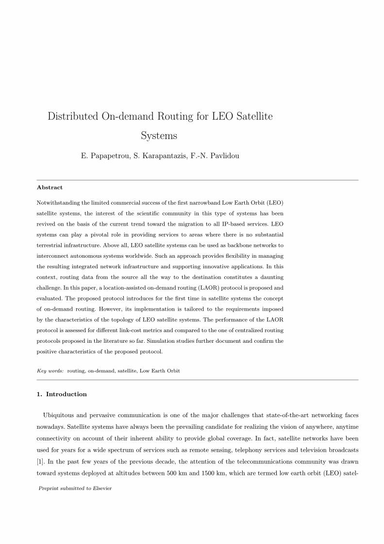
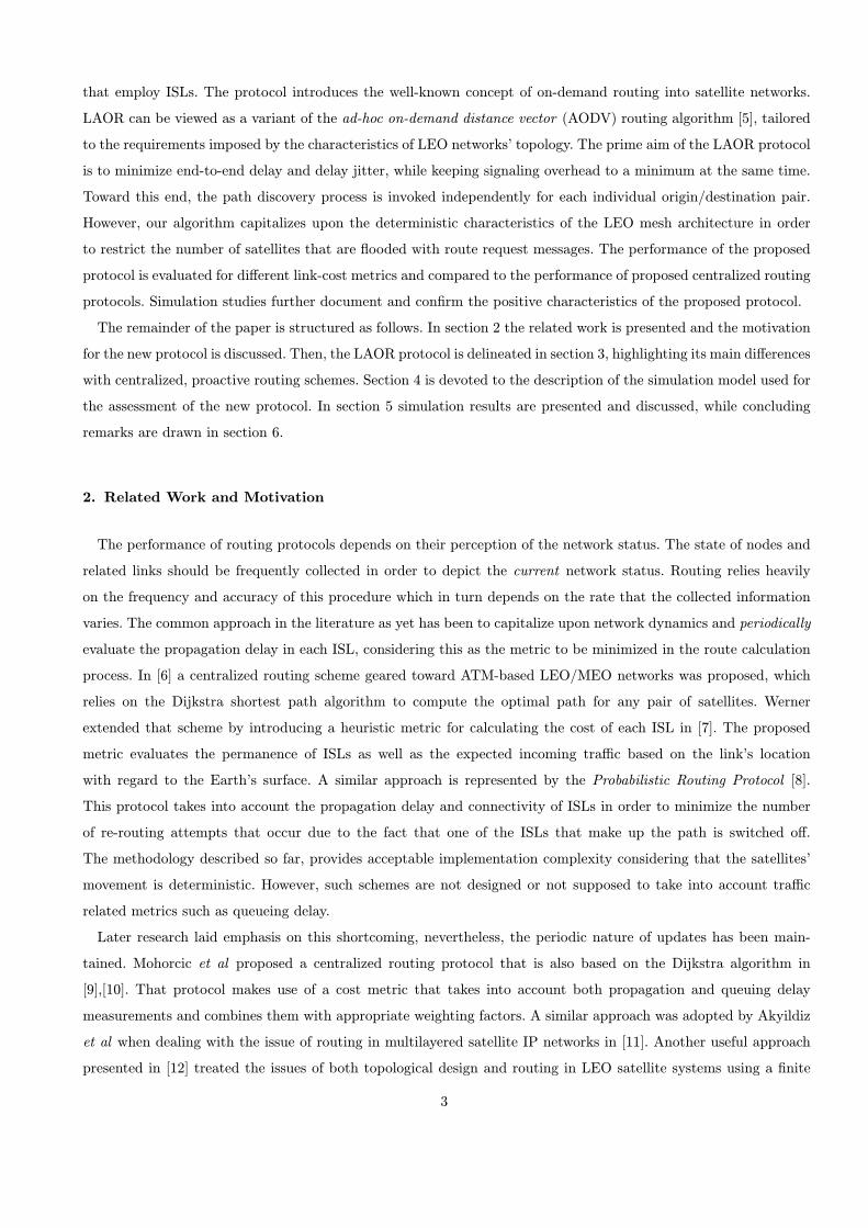
Fig. 1. Example of typical polar constellation Fig. 2. Resulting graph for typical polar constellation
However, the proposed algorithm capitalizes on the deterministic dynamics of the celestial network geometry to
introduce the concept of restricted route request area. Hence, the efiective area in which a route request is sent out
is minimized along with the related overhead. Moreover, the size and the dynamics of the satellite network, impose
severe modiflcations to mechanisms employed in traditional on-demand routing protocols, such as the maintenance
of cached routes, the use of cached replies, the initiation of a path discovery and so on. Additionally, the high
propagation delays and the non-uniform loading of a satellite network necessitate the use of both propagation and
queuing delay as metrics for making routing decisions, contrary to the use of hop count in the case of traditional on-
demand protocols in ad hoc networks. Finally, another key characteristic of the proposed protocol is its decentralized
operation, providing increased °exibility and reliability.
3. The Location Assisted On-demand Routing (LAOR) Protocol
3.1. System Model
In this study we consider near polar (or Walker star) constellations that employ ISLs. Polar constellations present
several attracting characteristics such as global coverage, simplifled constellation management, deployment of ISLs,
etc. In coherence to other studies we will study the most usual type of constellations where each satellite is assigned
four ISLs: two intra-plane ISLs (namely, links to the adjacent satellites in the same orbital plane) and two inter-plane
ISLs (that is, links to the neighboring satellites in the right-hand and left-hand orbital planes). While intra-plane
ISLs are maintained for the whole satellite period, inter-plane ISLs are broken as satellites come close to the poles
(flgure 1) due to adverse pointing and tracking conditions and reestablished when satellites move to lower latitudes.
Moreover, crossseam ISLs, namely links between satellites in counter-rotating orbits, are not used, as is the case
with the Iridium system. In this paper we are interested in routing within the network formed by satellites, called
space segment. This network, on its abstraction level, can be modeled as a graph G(V; E), comprising of a set of
nodes V and a set of edges E (flgure 2). It is clear that the size of V is jV j = NM , where N is the number of
the orbital planes that the system is comprised of and M is the number of satellites per plane. In this graph each
satellite is uniquely deflned by the pair of virtual coordinates (x; y), where x and y denote the orbital plane and
the position of the satellite in this plane respectively. Clearly, x 2 [0; N) and y 2 [0; M). The set of edges E models
5

ISLs connecting adjacent satellites. Consider an edge h(xk; yk); (xm; ym)i 2 E connecting satellites (xk; yk) and
(xm; ym). Then, for intraplane ISLs xk = xm and
ym =
(yk § 1; if yk § 1 2 [0; M)
yk § 1 ¤ M; otherwise(1)
while for interplane ISLs yk = ym and
xm =
(xk § 1; if xk § 1 2 [0; N)
not defined; otherwise(2)
It is clear from the previous equation that cross-seam ISLs are not considered in our study. The resulting graph
G(V; E) resembles a mesh network; however, ISLs are not permanent as mentioned before. To model this be-
havior, the availability of each edge h(xk; yk); (xm; ym)i 2 E is determined by the value a(xk;yk)!(xm;ym), which
equals 1 when the latitude of both satellites (xk; yk) and (xm; ym) is less than the latitude threshold. This means
that when either of the satellites resides within the polar regions, then a(xk;yk)!(xm;ym) = a(xm;ym)!(xk;yk) = 0.
Furthermore, each edge in the graph G(V; E) is characterized by the propagation delay dpr(xk;yk)!(xm;ym)of the
corresponding ISL, as well as the queueing delay dQ(xk;yk)!(xm;ym)encountered in the outgoing queue of the link.
Although dpr(xk;yk)!(xm;ym)= dpr(xm;ym)!(xk;yk)
, as far as queueing delay is concerned, in general it holds that
dQ(xk;yk)!(xm;ym)6= dQ(xm;ym)!(xk;yk)
since the loading of ISLs is not the same in both directions.
3.2. The Proposed Algorithm
In this section the details of the LAOR protocol are spelt out, accentuating its main performance disparities
in regard to periodic routing protocols proposed so far. The latter schemes are unable to capture variations in
network state during successive updates. The new protocol aims to provide °exible adaptation to network state.
To this end, it adopts an on-demand routing mechanism tailored to the requirements imposed by the topology of
LEO satellite systems. The protocol consists of three processes: i) request area formation, ii) path discovery, and
iii) route entry management. The path discovery process is independently invoked for each communication demand
and aims at discovering the shortest path for an origin/destination pair. It is based on exchanging route request
(RREQ) and route reply (RREP) messages, a technique extensively used in ad-hoc networks [16]. On-demand
routing has been reckoned to provide the means of accurate estimation of the network state at the expense of
routing overhead, produced by the usually °ood-based nature of the path discovery process. However, to minimize
the routing overhead, the proposed protocol capitalizes upon the predictable network topology, hence the name
location-assisted on-demand routing (LAOR) protocol. The protocol instead of performing a network-wide search,
prior to the initiation of the path discovery process, utilizes the request area formation process in order to minimize
the space segment area into which a route request will be broadcasted. Finally, the route entry management process
aims at managing stale routing information. Each process is discussed at greater length in the following subsections.
Since LAOR is an on-demand distance vector algorithm, each satellite vi 2 V must maintain a monotonically
increasing counter, called sequence number (seqi). The concept of sequence number is well-known in dynamic routing
algorithms ([16], [5]) and serves on the one hand to avoid loop formation and on the other to supersede stale cached
routes. The meaningfulness of this counter will be revealed in more detail later on. Furthermore, each satellite
6
should maintain a routing table (RTi) containing one entry for each destination in the network. The structure of
each route entry includes the following information:
{ rt dst: the address of the destination satellite.
{ rt dst seqnum: the last heard sequence number from the destination satellite.
{ rt next hop: the satellite to which a packet for the destination should be forwarded.
{ rt owner: this boolean fleld is true only if the route to rt dst was discovered as a result of a route request initiated
by this node. The fleld is used to indicate whether this node can use the route to reply to route requests from
other nodes.
{ rt path cost: the cost of the entire path, that is the sum of the ISLs’ costs. In this study we consider that the
cost of each ISL can be either its propagation delay or the sum of propagation delay and the queuing delay
encountered by a packet in the ISL’s outgoing queue.
{ rt path expiration time: the time instant at which the route entry and thus, the path, will become invalid due to
the switching ofi of an interplane ISL. This time can be calculated on account of the constellation deterministic
dynamics.
{ rt timestamp: the time instant at which the route entry was recorded.
In order to support the use of the last two flelds of a route entry, each satellite maintains a clock. Network-wide
synchronization of clocks is required and can be easily achieved on network set-up and maintained by the network
manager.
In addition to the routing table, each satellite vi 2 V , maintains a table ReqTi where it stores information
regarding route requests originated by other network nodes and seen by node vi. The table contains one entry for
each satellite in the network and each entry has the following flelds:
{ reqt orig: the address of the satellite that originated a route request. The existence of the entry implies that a
request originated by node reqt orig was received by the current satellite in the past.
{ reqt seqnum: the last heard sequence number carried in a route request from satellite reqt orig. As it will be
explained later on, each route request is uniquely identifled by the sequence number.
{ reqt cost: the cost from the originator of the request to the current satellite, recorded on the route request message
which is identifled by reqt seqnum.
{ reqt next hop: the address of the satellite that forwarded the route request message. This fleld indicates a path to
the originator of the request and is used for forwarding route reply messages back to the originator of a request.
The last fleld is necessary since for a given origin/destination pair, the forward and the reverse paths are not the
identical in general. Take for example the case that queueing delay is used as the cost of a link. As mentioned
in Section 3.1, in general dQ(xk;yk)!(xm;ym)6= dQ(xm;ym)!(xk;yk)
because the loading of ISLs is not the same in
both directions. Last but not least, each satellite has to maintain a queue, called LAOR queue. Since LAOR is an
on-demand protocol, it uses this queue to temporarily store packets that are waiting for a path to be set up.
3.2.1. Request Area Formation Process
When a ground terminal initiates a connection with another one or when an already communicating terminal is
handed over to a new satellite, the request area formation process is initiated by the serving satellite as soon as the up
7
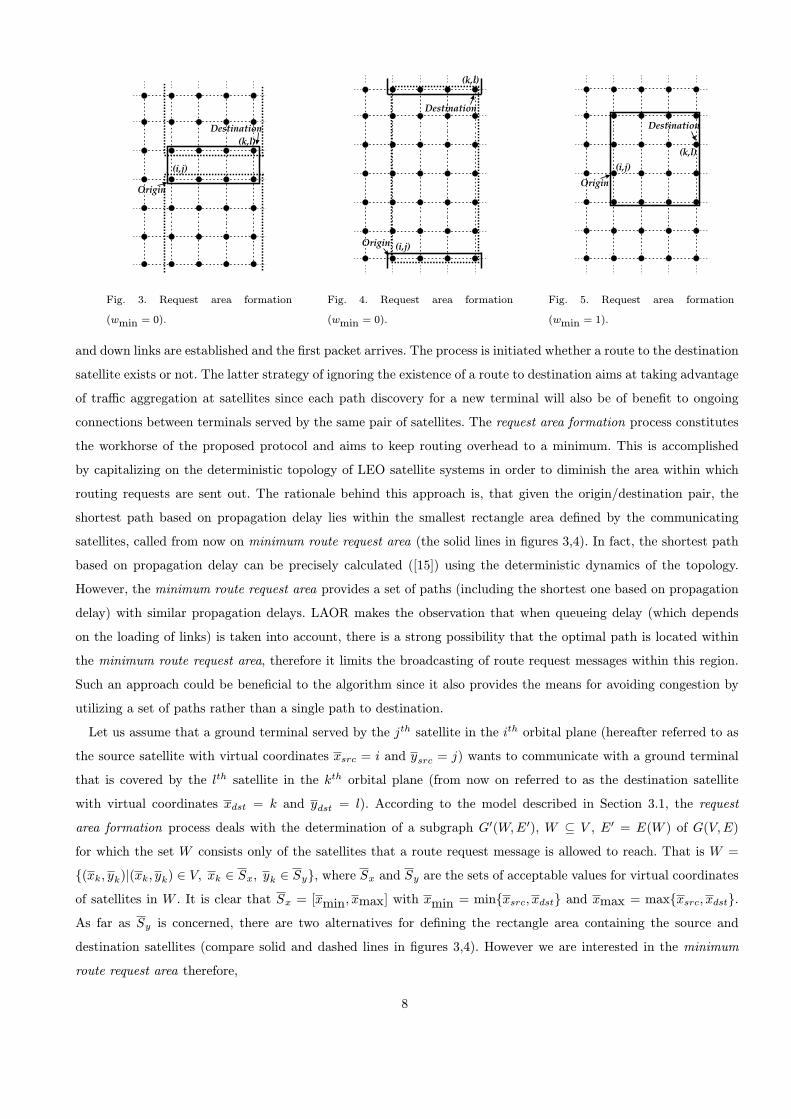
Fig. 3. Request area formation
(wmin = 0).
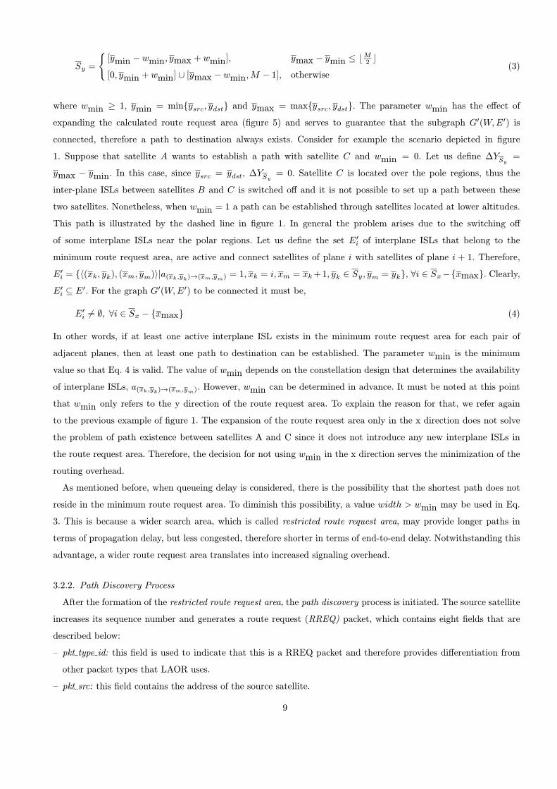
Fig. 4. Request area formation
(wmin = 0).
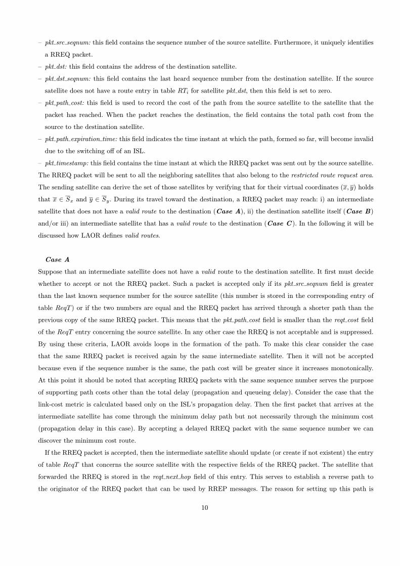
Fig. 5. Request area formation
(wmin = 1).
and down links are established and the flrst packet arrives. The process is initiated whether a route to the destination
satellite exists or not. The latter strategy of ignoring the existence of a route to destination aims at taking advantage
of tra–c aggregation at satellites since each path discovery for a new terminal will also be of beneflt to ongoing
connections between terminals served by the same pair of satellites. The request area formation process constitutes
the workhorse of the proposed protocol and aims to keep routing overhead to a minimum. This is accomplished
by capitalizing on the deterministic topology of LEO satellite systems in order to diminish the area within which
routing requests are sent out. The rationale behind this approach is, that given the origin/destination pair, the
shortest path based on propagation delay lies within the smallest rectangle area deflned by the communicating
satellites, called from now on minimum route request area (the solid lines in flgures 3,4). In fact, the shortest path
based on propagation delay can be precisely calculated ([15]) using the deterministic dynamics of the topology.
However, the minimum route request area provides a set of paths (including the shortest one based on propagation
delay) with similar propagation delays. LAOR makes the observation that when queueing delay (which depends
on the loading of links) is taken into account, there is a strong possibility that the optimal path is located within
the minimum route request area, therefore it limits the broadcasting of route request messages within this region.
Such an approach could be beneflcial to the algorithm since it also provides the means for avoiding congestion by
utilizing a set of paths rather than a single path to destination.
Let us assume that a ground terminal served by the jth satellite in the ith orbital plane (hereafter referred to as
the source satellite with virtual coordinates xsrc = i and ysrc = j) wants to communicate with a ground terminal
that is covered by the lth satellite in the kth orbital plane (from now on referred to as the destination satellite
with virtual coordinates xdst = k and ydst = l). According to the model described in Section 3.1, the request
area formation process deals with the determination of a subgraph G0(W; E0), W µ V , E0 = E(W ) of G(V; E)
for which the set W consists only of the satellites that a route request message is allowed to reach. That is W =
f(xk; yk)j(xk; yk) 2 V; xk 2 Sx; yk 2 Syg, where Sx and Sy are the sets of acceptable values for virtual coordinates
of satellites in W . It is clear that Sx = [xmin; xmax] with xmin = minfxsrc; xdstg and xmax = maxfxsrc; xdstg.
As far as Sy is concerned, there are two alternatives for deflning the rectangle area containing the source and
destination satellites (compare solid and dashed lines in flgures 3,4). However we are interested in the minimum
route request area therefore,
8
Sy =
([ymin ¡ wmin; ymax + wmin]; ymax ¡ ymin • b M
2 c[0; ymin + wmin] [ [ymax ¡ wmin; M ¡ 1]; otherwise
(3)
where wmin ‚ 1, ymin = minfysrc; ydstg and ymax = maxfysrc; ydstg. The parameter wmin has the efiect of
expanding the calculated route request area (flgure 5) and serves to guarantee that the subgraph G0(W; E0) is
connected, therefore a path to destination always exists. Consider for example the scenario depicted in flgure
1. Suppose that satellite A wants to establish a path with satellite C and wmin = 0. Let us deflne ¢YSy=
ymax ¡ ymin. In this case, since ysrc = ydst, ¢YSy= 0. Satellite C is located over the pole regions, thus the
inter-plane ISLs between satellites B and C is switched ofi and it is not possible to set up a path between these
two satellites. Nonetheless, when wmin = 1 a path can be established through satellites located at lower altitudes.
This path is illustrated by the dashed line in flgure 1. In general the problem arises due to the switching ofi
of some interplane ISLs near the polar regions. Let us deflne the set E0i of interplane ISLs that belong to the
minimum route request area, are active and connect satellites of plane i with satellites of plane i + 1. Therefore,
E0i = fh(xk; yk); (xm; ym)ija(xk;yk)!(xm;ym) = 1; xk = i; xm = xk +1; yk 2 Sy; ym = ykg, 8i 2 Sx ¡fxmaxg. Clearly,
E0i µ E0. For the graph G0(W; E0) to be connected it must be,
E0i 6= ;; 8i 2 Sx ¡ fxmaxg (4)
In other words, if at least one active interplane ISL exists in the minimum route request area for each pair of
adjacent planes, then at least one path to destination can be established. The parameter wmin is the minimum
value so that Eq. 4 is valid. The value of wmin depends on the constellation design that determines the availability
of interplane ISLs, a(xk;yk)!(xm;ym). However, wmin can be determined in advance. It must be noted at this point
that wmin only refers to the y direction of the route request area. To explain the reason for that, we refer again
to the previous example of flgure 1. The expansion of the route request area only in the x direction does not solve
the problem of path existence between satellites A and C since it does not introduce any new interplane ISLs in
the route request area. Therefore, the decision for not using wmin in the x direction serves the minimization of the
routing overhead.
As mentioned before, when queueing delay is considered, there is the possibility that the shortest path does not
reside in the minimum route request area. To diminish this possibility, a value width > wmin may be used in Eq.
3. This is because a wider search area, which is called restricted route request area, may provide longer paths in
terms of propagation delay, but less congested, therefore shorter in terms of end-to-end delay. Notwithstanding this
advantage, a wider route request area translates into increased signaling overhead.
3.2.2. Path Discovery Process
After the formation of the restricted route request area, the path discovery process is initiated. The source satellite
increases its sequence number and generates a route request (RREQ) packet, which contains eight flelds that are
described below:
{ pkt type id: this fleld is used to indicate that this is a RREQ packet and therefore provides difierentiation from
other packet types that LAOR uses.
{ pkt src: this fleld contains the address of the source satellite.
9
{ pkt src seqnum: this fleld contains the sequence number of the source satellite. Furthermore, it uniquely identifles
a RREQ packet.
{ pkt dst: this fleld contains the address of the destination satellite.
{ pkt dst seqnum: this fleld contains the last heard sequence number from the destination satellite. If the source
satellite does not have a route entry in table RTi for satellite pkt dst, then this fleld is set to zero.
{ pkt path cost: this fleld is used to record the cost of the path from the source satellite to the satellite that the
packet has reached. When the packet reaches the destination, the fleld contains the total path cost from the
source to the destination satellite.
{ pkt path expiration time: this fleld indicates the time instant at which the path, formed so far, will become invalid
due to the switching ofi of an ISL.
{ pkt timestamp: this fleld contains the time instant at which the RREQ packet was sent out by the source satellite.
The RREQ packet will be sent to all the neighboring satellites that also belong to the restricted route request area.
The sending satellite can derive the set of those satellites by verifying that for their virtual coordinates (x; y) holds
that x 2 Sx and y 2 Sy. During its travel toward the destination, a RREQ packet may reach: i) an intermediate
satellite that does not have a valid route to the destination (Case A), ii) the destination satellite itself (Case B)
and/or iii) an intermediate satellite that has a valid route to the destination (Case C ). In the following it will be
discussed how LAOR deflnes valid routes.
Case A
Suppose that an intermediate satellite does not have a valid route to the destination satellite. It flrst must decide
whether to accept or not the RREQ packet. Such a packet is accepted only if its pkt src seqnum fleld is greater
than the last known sequence number for the source satellite (this number is stored in the corresponding entry of
table ReqT ) or if the two numbers are equal and the RREQ packet has arrived through a shorter path than the
previous copy of the same RREQ packet. This means that the pkt path cost fleld is smaller than the reqt cost fleld
of the ReqT entry concerning the source satellite. In any other case the RREQ is not acceptable and is suppressed.
By using these criteria, LAOR avoids loops in the formation of the path. To make this clear consider the case
that the same RREQ packet is received again by the same intermediate satellite. Then it will not be accepted
because even if the sequence number is the same, the path cost will be greater since it increases monotonically.
At this point it should be noted that accepting RREQ packets with the same sequence number serves the purpose
of supporting path costs other than the total delay (propagation and queueing delay). Consider the case that the
link-cost metric is calculated based only on the ISL’s propagation delay. Then the flrst packet that arrives at the
intermediate satellite has come through the minimum delay path but not necessarily through the minimum cost
(propagation delay in this case). By accepting a delayed RREQ packet with the same sequence number we can
discover the minimum cost route.
If the RREQ packet is accepted, then the intermediate satellite should update (or create if not existent) the entry
of table ReqT that concerns the source satellite with the respective flelds of the RREQ packet. The satellite that
forwarded the RREQ is stored in the reqt next hop fleld of this entry. This serves to establish a reverse path to
the originator of the RREQ packet that can be used by RREP messages. The reason for setting up this path is
10

that in general a path toward the source satellite may not exist in the routing table RT . Furthermore, the reverse
path is not the minimum cost path in the direction from the intermediate satellite to the source satellite. Thus it
is not wise to store it in the routing table. After setting up the reverse route, the intermediate satellite updates the
pkt path cost fleld and forwards a replica of the RREQ packet to the contiguous satellites (excluding the one that
sent the RREQ) with virtual coordinates x 2 Sx, y 2 Sy which also satisfy the following inequality
x ‚ xc; if xsrc • xdst
or (5)
x • xc; if xsrc > xdst
where xc denotes the x¡coordinate of the intermediate satellite. No additional constraints are imposed for the
y¡coordinate, in order to guarantee the existence of at least one path, according to the rationale expressed at
the end of Section 3.2.1.The aim of this inequality is to forward a RREQ packet only toward the direction of the
destination satellite in order to keep overhead to a minimum. At this point it should be stressed that the intermediate
satellite will not forward a RREQ obtained from a path that will become invalid very shortly. To decide whether a
RREQ packet will be forwarded, the intermediate satellite uses the pkt path expiration time fleld of the RREQ and
validates the equation
t • pkt path expiration time ¡ expiration threshold (6)
where t is the current time and expiration threshold is a parameter of the LAOR protocol that determines the
minimum acceptable lifetime of a discovered path. Only if this equation holds will the satellite forward the RREQ
packet. The rationale behind this parameter is to avoid establishing a path that will become invalid very shortly
due to the switching ofi of one of the ISLs that make it up. If the RREQ is flnally forwarded, the intermediate
satellite calculates the expiration time texp of the link through which a replica of the RREQ will be forwarded.
Then it updates the pkt path expiration time fleld of the replica with minftexp; pkt path expiration timeg.
Case B
One case is that the RREQ will eventually reach the destination which has to decide (according to the procedure
described in Case A) on whether the RREQ is acceptable or not. If so, the satellite increases its sequence number,
updates ReqT and produces a RREP message that contains the following information:
{ pkt typeid: this fleld indicates that this is a RREP packet.
{ pkt src: this fleld contains the address of the satellite that produces the RREP (the destination of the RREQ or
an intermediate).
{ pkt dst: this fleld contains the address of the source satellite that produced the RREQ.
{ pkt dst seqnum: this fleld is set equal to the sequence number of the satellite that produces the RREP. This
number uniquely identifles the RREP message.
{ pkt path cost: this fleld is set equal to the value written in the corresponding fleld of the RREQ packet, which is
the cost of the path from the source satellite to the destination.
{ pkt path expiration time: this fleld communicates the path’s expiration time instant to the source satellite and is
set equal to the respective fleld of the RREQ packet.
11

{ pkt timestamp: this fleld is set equal to the corresponding fleld of the RREQ packet.
The RREP message is forwarded to the source of the route request by using the entries concerning the source
satellite in the tables ReqT of the intermediate satellites. Upon receipt of a RREP, an intermediate satellite stores
in its routing table RT a path to the destination satellite according to the data carried on the RREP packet.
However, the flelds rt path cost and rt expiration time are not stored because the respective values carried in the
RREP packet correspond to the path from the source to the destination satellite and not to the path from the
intermediate satellite to the destination. Furthermore, the fleld pkt owner is set to false to indicate that the satellite
is an intermediate in the path. This means that the flelds rt path cost and rt expiration time do not carry valid
information and therefore can not be used for replying to other route requests. It must be noted at this point that
if a route entry for the destination satellite already exists, then it is superseded only if the pkt dst seqnum carried
on the RREP is greater than the rt dst seqnum of the existing entry or if the two numbers are the same and the
path cost of the new path is smaller than the cost of the existing entry. Finally, the source satellite can commence
data transmission as soon as the flrst RREP is received and can later update its routing information if it learns of
a better route. It must be noted that in the route entry stored by the source satellite the fleld pkt owner is set to true.
Case C
There is a possibility that a RREQ packet will produce a RREP before reaching the destination. This happens when
it reaches an intermediate node that holds a valid route to the destination. In order for a route to be considered valid,
its value rt owner should be true. Furthermore, its rt dst seqnum fleld must be greater than the pkt dst seqnum
contained in the RREQ packet and it must have been recorded after the time instant at which the RREQ was sent
out (this is indicated by the pkt timestamp fleld of the RREQ packet). The condition regarding sequence numbers
is also used in other dynamic routing protocols such as AODV [5] and guarantees loop-free paths. The second
condition is used to limit replies by intermediate nodes only to those having up-to-date routes. Furthermore, a
route is considered valid if its lifetime is acceptable based on equation (6). In this case, the minimum of the time
instant carried in the RREQ packet and the expiration time of the cashed route is used as path expiration time.
After conflrming that the RREQ packet can be accepted (by the same procedure as in case A), the intermediate
satellite increases its sequence number and produces a RREP. The path cost carried in the the RREP packet is the
sum of the cost carried in the RREQ packet and the cost of the stored route.
3.2.3. Route Entry Management
As mentioned earlier, the path’s expiration time is stored in each route entry. The purpose of this information
is to purge the route entry for the destination satellite before the time instant at which the route is considered
to become invalid. Nonetheless, a new path should be established prior to the expiration of the previous one. The
aim is to ensure that no packet will be in-°ight when the path becomes invalid. To this end, a satellite vi initiates
the path discovery process for a destination satellite at time rt path expiration time - expiration threshold, where
rt path expiration time is the value of the entry regarding destination satellite, which is stored in table RTi.
Each path discovery process may fail to determine a path to destination. Since the existence of at least one path
within the restricted route request area is guaranteed, failure to discover a path is the result of dropping RREQ or
12
RREP packets due to congestion. In this case the path discovery process is repeated periodically until a path is
found.
4. Simulation Model
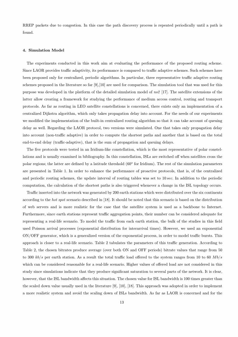
The experiments conducted in this work aim at evaluating the performance of the proposed routing scheme.
Since LAOR provides tra–c adaptivity, its performance is compared to tra–c adaptive schemes. Such schemes have
been proposed only for centralized, periodic algorithms. In particular, three representative tra–c adaptive routing
schemes proposed in the literature so far [9],[10] are used for comparison. The simulation tool that was used for this
purpose was developed in the platform of the detailed simulation model of ns2 [17]. The satellite extensions of the
latter allow creating a framework for studying the performance of medium access control, routing and transport
protocols. As far as routing in LEO satellite constellations is concerned, there exists only an implementation of a
centralized Dijkstra algorithm, which only takes propagation delay into account. For the needs of our experiments
we modifled the implementation of the built-in centralized routing algorithm so that it can take account of queuing
delay as well. Regarding the LAOR protocol, two versions were simulated. One that takes only propagation delay
into account (non-tra–c adaptive) in order to compute the shortest paths and another that is based on the total
end-to-end delay (tra–c-adaptive), that is the sum of propagation and queuing delays.
The flve protocols were tested in an Iridium-like constellation, which is the most representative of polar constel-
lations and is usually examined in bibliography. In this constellation, ISLs are switched ofi when satellites cross the
polar regions; the latter are deflned by a latitude threshold (60o for Iridium). The rest of the simulation parameters
are presented in Table 1. In order to enhance the performance of proactive protocols, that is, of the centralized
and periodic routing schemes, the update interval of routing tables was set to 10 sec. In addition to the periodic
computation, the calculation of the shortest paths is also triggered whenever a change in the ISL topology occurs.
Tra–c inserted into the network was generated by 200 earth stations which were distributed over the six continents
according to the hot spot scenario described in [18]. It should be noted that this scenario is based on the distribution
of web servers and is more realistic for the case that the satellite system is used as a backbone to Internet.
Furthermore, since earth stations represent tra–c aggregation points, their number can be considered adequate for
representing a real-life scenario. To model the tra–c from each earth station, the bulk of the studies in this fleld
used Poisson arrival processes (exponential distribution for interarrival times). However, we used an exponential
ON/OFF generator, which is a generalized version of the exponential process, in order to model tra–c bursts. This
approach is closer to a real-life scenario. Table 2 tabulates the parameters of this tra–c generation. According to
Table 2, the chosen bitrates produce average (over both ON and OFF periods) bitrate values that range from 50
to 300 kb=s per earth station. As a result the total tra–c load ofiered to the system ranges from 10 to 60 Mb=s
which can be considered reasonable for a real-life scenario. Higher values of ofiered load are not considered in this
study since simulations indicate that they produce signiflcant saturation to several parts of the network. It is clear,
however, that the ISL bandwidth afiects this situation. The chosen value for ISL bandwidth is 100 times greater than
the scaled down value usually used in the literature [9], [10], [18]. This approach was adopted in order to implement
a more realistic system and avoid the scaling down of ISLs bandwidth. As far as LAOR is concerned and for the
13

Table 1
Simulation parameters
] of orbits 6
] satellites pre plane 11
Satellite altitude 780 km
Inclination 86:4o
Interplane separation 31:6o
Min. elevation angle 8:2o
Cross-seam ISLs No
] of ISLs 2 intra-plane + 2 inter-plane
ISL latitude threshold § 60o
Up/downlink bandwidth 15 Mb/s
ISL bandwidth 10 Mb/s
ISL LL queue size 500 packets
LAOR queue size 3000 packets
Simulation duration 6050 sec
Table 2
Tra–c generator’s parameters
Packet size 1500 bytes
\On"period 0.3 sec
\Ofi"period 0.9 sec
bitrate during \On"periods 200 kb/s - 1200 kb/s
needs of the presented simulation study, the size of RREQ packets was 52 bytes while the size of RREP packets was
48 bytes. This breaks down to 2 bytes for the pkt type id fleld, 8 bytes for the flelds containing sequence numbers,
4 bytes for every other fleld and a link-layer header of 14 bytes. Obviously, the choice of fleld sizes represents the
worst case and underestimates the performance of LAOR in terms of byte overhead.
4.1. Link Cost Metrics
In this subsection we comment on the difierent link-cost metrics that the examined routing protocols employ. As
far as LAOR is concerned, according to Section 3.2 there are two options. LAOR may use only propagation delay as
the link-cost metric or it can also take the queuing delay into account. In both cases, the delay that LAOR records
in each link (propagation and, if needed, queuing) is the one encountered by the RREQ packet during its travel
to the destination. On the other hand, the link-cost function used by the centralized-periodic routing protocols is
14

based on a combination of propagation and queueing delays and is given by [9],[10]
Link cost = W FPD £ P D + WFQD £ QD (7)
where P D and QD denote the propagation delay and queuing delay respectively, while WFPD and WFQD represent
the weighting factors given to them. The flrst of these three protocols is based only on propagation delay, thus
WFPD was set to 1 and WFQD to 0. The remaining two protocols take queuing delay into account as well. In
[9],[10] difierent combinations of WFPD and W FQD were studied. For the sake of fairness, we set WFPD = 1 and
WFQD = 1 because this combination yields the best performance. Furthermore, any other combination is superflcial
and does not accurately re°ect the network state. Nonetheless, there exists a difierence between these two protocols,
which lies in the method according to which the queuing delay is estimated. In the flrst algorithm, queuing delay is
taken into consideration by means of an average value over the update interval of routing tables. The second one
uses an exponential forgetting function (EFF). Both methods are frequently used by researchers [19],[20]. Let us now
focus our attention on the latter method. To derive a feasible methodology for estimating queueing delay we take
advantage of the ability of Layer-2 protocols to provide statistics related to the ISL utilization. Then, according to
the M=M=1 queuing model [21] the mean number of packets in a queue MPQ can be estimated by
MPQ =uISL
1 ¡ uISL(8)
where uISL is the mean link utilization provided by link layer (LL). When EFF is employed, link utilization is
calculated as follows 1 :
ukISL = link state + decay ¢ (uk¡1
ISL ¡ link state) (9)
where ukISL and uk¡1
ISL are the estimated link utilizations when the kth and (k ¡ 1)th packets arrive at the interface
queue in the current time interval. Concerning link state, it is set to 0 if there is no packet either in the interface
queue or under transmission, otherwise it is set to 1. The parameter decay denotes the forgetting rate and is deflned
as:
decay = e¢tk (10)
where ¢tk is the time interval between the arrivals of packets k and k ¡ 1 in the queue. Then, the queuing delay
can readily be estimated by the following expression:
Queuing delay = MPQPacket size
ISL throughput(11)
where the fraction denotes the packet transmission delay.
4.2. Performance Metrics
To evaluate the performance of the examined protocols, four performance metrics are used:
{ mean end-to-end delay: the average time needed by the algorithm to successfully deliver packets to their
destination. This metric directly evaluates the ability of the algorithm to provide shortest paths.
1 This is the built-in method in ns2.
15

{ mean delay jitter: the average delay variation experienced by two consecutive data packets. This metric provides
an assessment of the algorithm’s stability.
{ end-to-end packet delivery ratio: the ratio of data packets delivered to the data packets generated. Hereafter,
we will refer to this metric as delivery ratio.
{ normalized routing overhead: the number of routing packets transmitted per data packet delivered (packet
overhead). Another more meaningful metric is represented by the ratio of the total number of bytes related to
routing packets to the total number of bytes of data packets (byte overhead).
In general, the flrst and the third metrics are reckoned to be the most important performance indicators when
evaluating a routing protocol. However, when it comes to streaming applications, such as VoIP (telephony) and
audio/video streaming, mean delay jitter is of paramount importance and should be kept to a minimum. Last but
not least, despite the vast literature on routing in non-GEO satellite systems, the acute issue of routing overhead
brought about by the exchange of information among satellites has scarcely been addressed. The fourth metric
shows how e–ciently the system resources are utilized and provides an assessment of the protocol ability to scale.
5. Simulation Results and Discussion
In this section we present an extensive simulation study of the proposed protocol performance. The study com-
prises three sets of experiments. The flrst set is devoted to the comparison of LAOR with the routing schemes
mentioned in the previous section. For the sake of clarity, these protocols are presented below, along with the
notations used in the rest of the paper.
{ Central.-PD: the centralized-periodic routing scheme when the link-cost metric is propagation delay.
{ Central.-AV: the centralized-periodic routing scheme when the link-cost metric is the sum of propagation delay
and average queuing delay.
{ Central.-EXP: the centralized-periodic routing scheme when the link-cost metric is the sum of propagation
delay and the queuing delay perceived by the exponential forgetting function.
{ LAOR-PD: the LAOR protocol when the link-cost metric is propagation delay.
{ LAOR-TD: the LAOR protocol when the link-cost metric is the sum of propagation and queuing delay.
The flve protocols are compared in terms of the metrics described in Section 4.2 for various tra–c generation rates.
The second experiment explores the efiect of the parameter width in the performance of LAOR. Finally, the third
experiment investigates the impact of bursty tra–c on the performance of both LAOR and centralized schemes. At
this point it should be noted that the presented results represent average values over 10 independent simulation
runs. That number of runs provided 99% confldence intervals of §4% at worst.
5.1. Performance vs tra–c load
This set of experiments represents the fundamental comparison of LAOR with periodic routing schemes. For this
set of comparisons, the parameters expiration threshold and width of the LAOR protocol were set to 0:5 sec and
1 respectively. The rationale behind the selection of an expiration threshold equal to 0:5 sec is to ensure that no
packets will be in-°ight when the path will become invalid. Recall also that width determines the boundaries of
16

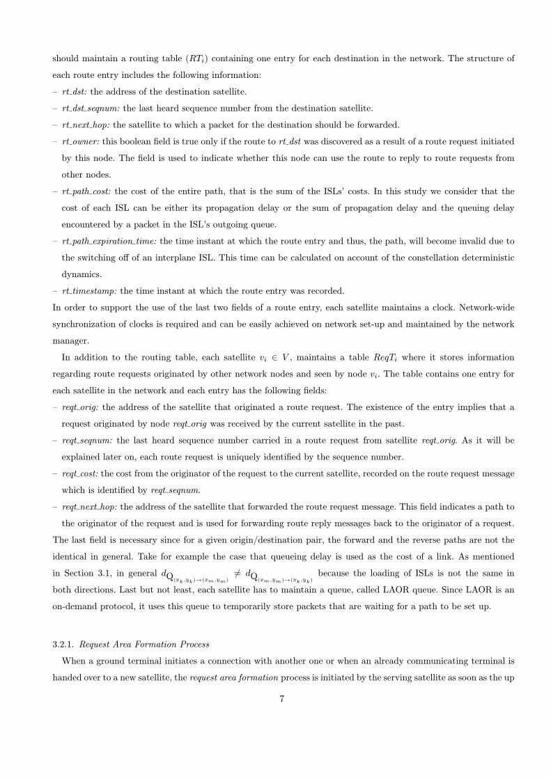
Fig. 6. Mean end-to-end delay vs terminal’s bitrate
the restricted route request area with respect to the y-axis. For the Iridium system, the minimum value that can be
used for width is wmin = 1.
Figure 6 depicts mean end-to-end delay versus terminal’s bitrate. It becomes evident from this flgure that the
LAOR protocol constitutes a signiflcant improvement on periodic schemes. A stunning amelioration is observed for
high bitrates. In particular, for bitrates higher than 1000 kb=s mean end-to-end delay is dropped down by half. It
must be noted that the performance of routing algorithms is more important in conditions of high system loading,
since each system is desired to maximize the use of its resources. Such high loading conditions are represented by
bitrates greater than 1000 kb=s. At the same time, in such conditions the overall ofiered tra–c to the system is 50
to 60 Mb=s. The striking results of the LAOR protocol are ascribed to its ability to capture tra–c variations as
well as changes in the propagation delay of ISLs, which stems from the fact that LAOR makes routing decisions
upon request. As a result, the adaptation to the network state is smoother. Indeed, the LAOR protocol yields an
enhanced performance compared to the three periodic routing schemes, even when the link-cost metric is propagation
delay. On the other hand, when queuing delay is taken into account, the ability of LAOR to derive a path upon
request, leads to the distribution of tra–c to multiple almost equivalent paths. Another approach in achieving
the same goal would be to calculate o†ine the k best paths based on only propagation delay and then split the
tra–c among these paths. However, this approach introduces further complexity regarding the determination of
the best k for each constellation and the maintenance of state for each path. The latter is of major importance
since parts of a path may be used by several origin/destination pairs. Therefore, the timely collection of path
information is required and involves the tradeofi between accuracy and overhead. However, LAOR, through its
on-demand operation, provides smooth adaptation to the network state with low overhead. Another interesting
result is that there exist no difierences in the performance of the three periodic routing schemes, albeit one would
expect the schemes that take account of queuing delay to outperform the one that relies only on propagation delay.
This behavior can be explained by the fact that as soon as a new path is computed for a pair of satellites, all
communications between terminals served by these two satellites will be forced to use this new path, hence making
it congested. This phenomenon is repeated in every update cycle and is known as oscillation. It is more intense in
connectionless communications, such as IP forwarding, since data °ows quickly adapt to path switching.
17
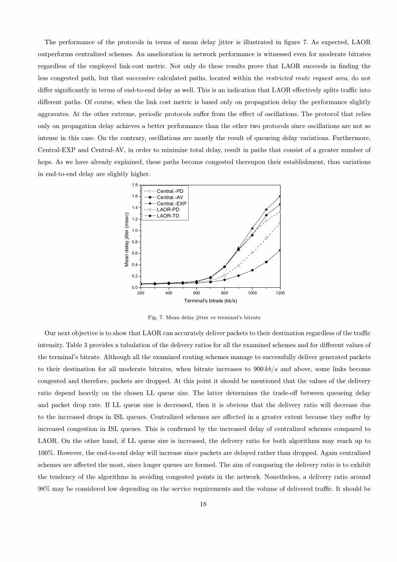
The performance of the protocols in terms of mean delay jitter is illustrated in flgure 7. As expected, LAOR
outperforms centralized schemes. An amelioration in network performance is witnessed even for moderate bitrates
regardless of the employed link-cost metric. Not only do these results prove that LAOR succeeds in flnding the
less congested path, but that successive calculated paths, located within the restricted route request area, do not
difier signiflcantly in terms of end-to-end delay as well. This is an indication that LAOR efiectively splits tra–c into
difierent paths. Of course, when the link cost metric is based only on propagation delay the performance slightly
aggravates. At the other extreme, periodic protocols sufier from the efiect of oscillations. The protocol that relies
only on propagation delay achieves a better performance than the other two protocols since oscillations are not so
intense in this case. On the contrary, oscillations are mostly the result of queueing delay variations. Furthermore,
Central-EXP and Central-AV, in order to minimize total delay, result in paths that consist of a greater number of
hops. As we have already explained, these paths become congested thereupon their establishment, thus variations
in end-to-end delay are slightly higher.
Fig. 7. Mean delay jitter vs terminal’s bitrate
Our next objective is to show that LAOR can accurately deliver packets to their destination regardless of the tra–c
intensity. Table 3 provides a tabulation of the delivery ratios for all the examined schemes and for difierent values of
the terminal’s bitrate. Although all the examined routing schemes manage to successfully deliver generated packets
to their destination for all moderate bitrates, when bitrate increases to 900 kb=s and above, some links become
congested and therefore, packets are dropped. At this point it should be mentioned that the values of the delivery
ratio depend heavily on the chosen LL queue size. The latter determines the trade-ofi between queueing delay
and packet drop rate. If LL queue size is decreased, then it is obvious that the delivery ratio will decrease due
to the increased drops in ISL queues. Centralized schemes are afiected in a greater extent because they sufier by
increased congestion in ISL queues. This is conflrmed by the increased delay of centralized schemes compared to
LAOR. On the other hand, if LL queue size is increased, the delivery ratio for both algorithms may reach up to
100%. However, the end-to-end delay will increase since packets are delayed rather than dropped. Again centralized
schemes are afiected the most, since longer queues are formed. The aim of comparing the delivery ratio is to exhibit
the tendency of the algorithms in avoiding congested points in the network. Nonetheless, a delivery ratio around
98% may be considered low depending on the service requirements and the volume of delivered tra–c. It should be
18
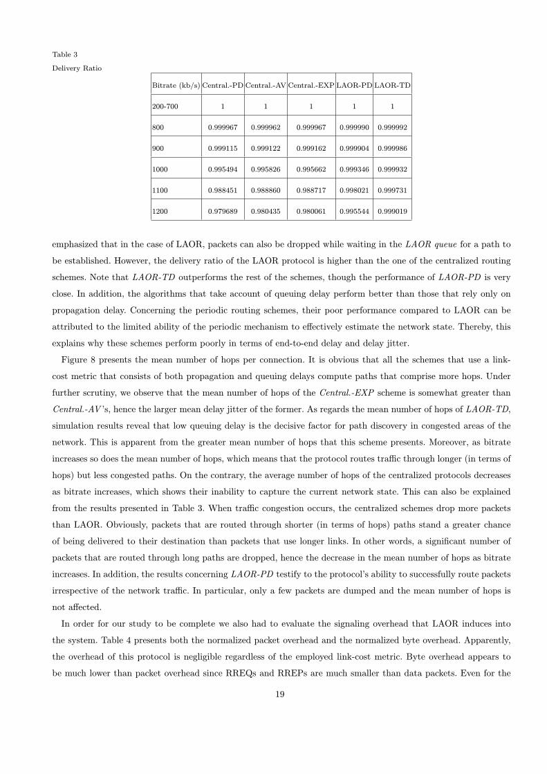
Table 3
Delivery Ratio
Bitrate (kb/s) Central.-PD Central.-AV Central.-EXP LAOR-PD LAOR-TD
200-700 1 1 1 1 1
800 0.999967 0.999962 0.999967 0.999990 0.999992
900 0.999115 0.999122 0.999162 0.999904 0.999986
1000 0.995494 0.995826 0.995662 0.999346 0.999932
1100 0.988451 0.988860 0.988717 0.998021 0.999731
1200 0.979689 0.980435 0.980061 0.995544 0.999019
emphasized that in the case of LAOR, packets can also be dropped while waiting in the LAOR queue for a path to
be established. However, the delivery ratio of the LAOR protocol is higher than the one of the centralized routing
schemes. Note that LAOR-TD outperforms the rest of the schemes, though the performance of LAOR-PD is very
close. In addition, the algorithms that take account of queuing delay perform better than those that rely only on
propagation delay. Concerning the periodic routing schemes, their poor performance compared to LAOR can be
attributed to the limited ability of the periodic mechanism to efiectively estimate the network state. Thereby, this
explains why these schemes perform poorly in terms of end-to-end delay and delay jitter.
Figure 8 presents the mean number of hops per connection. It is obvious that all the schemes that use a link-
cost metric that consists of both propagation and queuing delays compute paths that comprise more hops. Under
further scrutiny, we observe that the mean number of hops of the Central.-EXP scheme is somewhat greater than
Central.-AV ’s, hence the larger mean delay jitter of the former. As regards the mean number of hops of LAOR-TD,
simulation results reveal that low queuing delay is the decisive factor for path discovery in congested areas of the
network. This is apparent from the greater mean number of hops that this scheme presents. Moreover, as bitrate
increases so does the mean number of hops, which means that the protocol routes tra–c through longer (in terms of
hops) but less congested paths. On the contrary, the average number of hops of the centralized protocols decreases
as bitrate increases, which shows their inability to capture the current network state. This can also be explained
from the results presented in Table 3. When tra–c congestion occurs, the centralized schemes drop more packets
than LAOR. Obviously, packets that are routed through shorter (in terms of hops) paths stand a greater chance
of being delivered to their destination than packets that use longer links. In other words, a signiflcant number of
packets that are routed through long paths are dropped, hence the decrease in the mean number of hops as bitrate
increases. In addition, the results concerning LAOR-PD testify to the protocol’s ability to successfully route packets
irrespective of the network tra–c. In particular, only a few packets are dumped and the mean number of hops is
not afiected.
In order for our study to be complete we also had to evaluate the signaling overhead that LAOR induces into
the system. Table 4 presents both the normalized packet overhead and the normalized byte overhead. Apparently,
the overhead of this protocol is negligible regardless of the employed link-cost metric. Byte overhead appears to
be much lower than packet overhead since RREQs and RREPs are much smaller than data packets. Even for the
19
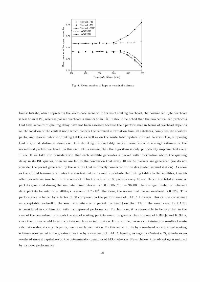
Fig. 8. Mean number of hops vs terminal’s bitrate
lowest bitrate, which represents the worst-case scenario in terms of routing overhead, the normalized byte overhead
is less than 0:1%, whereas packet overhead is smaller than 1%. It should be noted that the two centralized protocols
that take account of queuing delay have not been assessed because their performance in terms of overhead depends
on the location of the central node which collects the required information from all satellites, computes the shortest
paths, and disseminates the routing tables, as well as on the route table update interval. Nevertheless, supposing
that a ground station is shouldered this daunting responsibility, we can come up with a rough estimate of the
normalized packet overhead. To this end, let us assume that the algorithm is only periodically implemented every
10 sec. If we take into consideration that each satellite generates a packet with information about the queuing
delay in its ISL queues, then we are led to the conclusion that every 10 sec 65 packets are generated (we do not
consider the packet generated by the satellite that is directly connected to the designated ground station). As soon
as the ground terminal computes the shortest paths it should distribute the routing tables to the satellites, thus 65
other packets are inserted into the network. This translates in 130 packets every 10 sec. Hence, the total amount of
packets generated during the simulated time interval is 130 ¢ (6050=10) = 96800. The average number of delivered
data packets for bitrate = 200kb=s is around 4:7 ¢ 106, therefore, the normalized packet overhead is 0:02%. This
performance is better by a factor of 50 compared to the performance of LAOR. However, this can be considered
an acceptable trade-ofi if the small absolute size of packet overhead (less than 1% in the worst case) for LAOR
is considered in combination with its improved performance. Furthermore, it is reasonable to believe that in the
case of the centralized protocols the size of routing packets would be greater than the one of RREQs and RREPs,
since the former would have to contain much more information. For example, packets containing the results of route
calculation should carry 65 paths, one for each destination. On this account, the byte overhead of centralized routing
schemes is expected to be greater than the byte overhead of LAOR. Finally, as regards Central.-PD, it induces no
overhead since it capitalizes on the deterministic dynamics of LEO networks. Nevertheless, this advantage is nullifled
by its poor performance.
20
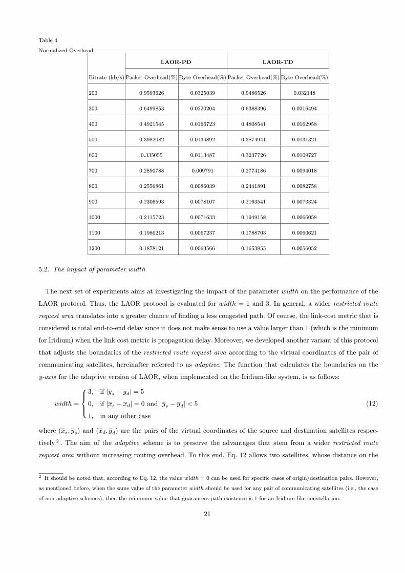
Table 4
Normalized Overhead
LAOR-PD LAOR-TD
Bitrate (kb/s) Packet Overhead(%) Byte Overhead(%) Packet Overhead(%) Byte Overhead(%)
200 0.9593626 0.0325039 0.9486526 0.032148
300 0.6499853 0.0220204 0.6388396 0.0216494
400 0.4921545 0.0166723 0.4808541 0.0162958
500 0.3982082 0.0134892 0.3874941 0.0131321
600 0.335055 0.0113487 0.3237726 0.0109727
700 0.2890788 0.009791 0.2774186 0.0094018
800 0.2556861 0.0086039 0.2441891 0.0082758
900 0.2306593 0.0078107 0.2163541 0.0073324
1000 0.2115723 0.0071633 0.1949158 0.0066058
1100 0.1986213 0.0067237 0.1788703 0.0060621
1200 0.1878121 0.0063566 0.1653855 0.0056052
5.2. The impact of parameter width
The next set of experiments aims at investigating the impact of the parameter width on the performance of the
LAOR protocol. Thus, the LAOR protocol is evaluated for width = 1 and 3. In general, a wider restricted route
request area translates into a greater chance of flnding a less congested path. Of course, the link-cost metric that is
considered is total end-to-end delay since it does not make sense to use a value larger than 1 (which is the minimum
for Iridium) when the link cost metric is propagation delay. Moreover, we developed another variant of this protocol
that adjusts the boundaries of the restricted route request area according to the virtual coordinates of the pair of
communicating satellites, hereinafter referred to as adaptive. The function that calculates the boundaries on the
y-axis for the adaptive version of LAOR, when implemented on the Iridium-like system, is as follows:
width =
8><>:
3; if jys ¡ ydj = 5
0; if jxs ¡ xdj = 0 and jys ¡ ydj < 5
1; in any other case
(12)
where (xs; ys) and (xd; yd) are the pairs of the virtual coordinates of the source and destination satellites respec-
tively 2 . The aim of the adaptive scheme is to preserve the advantages that stem from a wider restricted route
request area without increasing routing overhead. To this end, Eq. 12 allows two satellites, whose distance on the
2 It should be noted that, according to Eq. 12, the value width = 0 can be used for speciflc cases of origin/destination pairs. However,
as mentioned before, when the same value of the parameter width should be used for any pair of communicating satellites (i.e., the case
of non-adaptive schemes), then the minimum value that guarantees path existence is 1 for an Iridium-like constellation.
21
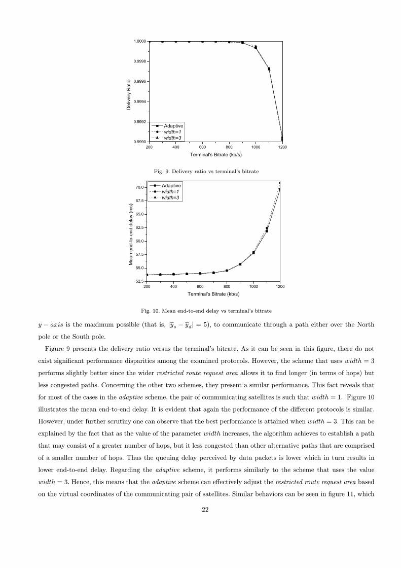
Fig. 9. Delivery ratio vs terminal’s bitrate
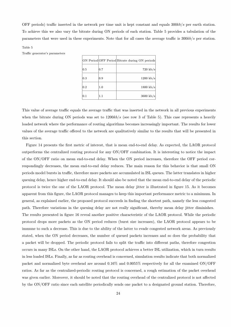
Fig. 10. Mean end-to-end delay vs terminal’s bitrate
y ¡ axis is the maximum possible (that is, jys ¡ ydj = 5), to communicate through a path either over the North
pole or the South pole.
Figure 9 presents the delivery ratio versus the terminal’s bitrate. As it can be seen in this flgure, there do not
exist signiflcant performance disparities among the examined protocols. However, the scheme that uses width = 3
performs slightly better since the wider restricted route request area allows it to flnd longer (in terms of hops) but
less congested paths. Concerning the other two schemes, they present a similar performance. This fact reveals that
for most of the cases in the adaptive scheme, the pair of communicating satellites is such that width = 1. Figure 10
illustrates the mean end-to-end delay. It is evident that again the performance of the difierent protocols is similar.
However, under further scrutiny one can observe that the best performance is attained when width = 3. This can be
explained by the fact that as the value of the parameter width increases, the algorithm achieves to establish a path
that may consist of a greater number of hops, but it less congested than other alternative paths that are comprised
of a smaller number of hops. Thus the queuing delay perceived by data packets is lower which in turn results in
lower end-to-end delay. Regarding the adaptive scheme, it performs similarly to the scheme that uses the value
width = 3. Hence, this means that the adaptive scheme can efiectively adjust the restricted route request area based
on the virtual coordinates of the communicating pair of satellites. Similar behaviors can be seen in flgure 11, which
22

Fig. 11. Mean delay jitter vs terminal’s bitrate
Fig. 12. Packet overhead vs terminal’s bitrate Fig. 13. Byte overhead vs terminal’s bitrate
depicts the mean delay jitter. The next set of flgures illustrates the routing overhead. We expect that as the value
of the parameter width increases, routing overhead will increase as well. Figure 12 depicts the normalized packet
overhead, while flgure 13 presents the normalized byte overhead. These flgures substantiate our expectations. The
best performance is attained by the scheme with width = 1, the performance of the adaptive scheme is very close
though. As expected, the scheme with width = 3 presents the worst performance on account of the greater number
of routing packets that are generated. Nevertheless, the packet and byte overheads are still low. From the last four
flgures we are led to the conclusion that the adaptive scheme attains the best overall performance, however the
performance disparities among these three schemes are not really signiflcant.
5.3. Performance under bursty tra–c
In the third set of experiments, the LAOR-TD protocol, that is, the LAOR protocol when the link-cost metric
is based on the total end-to-end delay, is compared to the Central.-AV protocol for difierent combinations of the
ON/OFF periods of the tra–c generator. The aim of this set of experiments is to demonstrate that the performance
disparity between these two routing protocols is not afiected by a change in the ON/OFF ratio of the tra–c
generator. The latter indicates how smoothly or abruptly tra–c is inserted into the network, i.e., how bursty the
tra–c is. Therefore in this set of experiments we vary the ON/OFF ratio while the average (over both ON and
23
OFF periods) tra–c inserted in the network per time unit is kept constant and equals 300kb=s per earth station.
To achieve this we also vary the bitrate during ON periods of each station. Table 5 provides a tabulation of the
parameters that were used in these experiments. Note that for all cases the average tra–c is 300kb=s per station.
Table 5
Tra–c generator’s parameters
ON Period OFF Period Bitrate during ON periods
0.5 0.7 720 kb/s
0.3 0.9 1200 kb/s
0.2 1.0 1800 kb/s
0.1 1.1 3600 kb/s
This value of average tra–c equals the average tra–c that was inserted in the network in all previous experiments
when the bitrate during ON periods was set to 1200kb=s (see row 3 of Table 5). This case represents a heavily
loaded network where the performance of routing algorithms becomes increasingly important. The results for lower
values of the average tra–c ofiered to the network are qualitatively similar to the results that will be presented in
this section.
Figure 14 presents the flrst metric of interest, that is mean end-to-end delay. As expected, the LAOR protocol
outperforms the centralized routing protocol for any ON/OFF combination. It is interesting to notice the impact
of the ON/OFF ratio on mean end-to-end delay. When the ON period increases, therefore the OFF period cor-
respondingly decreases, the mean end-to-end delay reduces. The main reason for this behavior is that small ON
periods model bursts in tra–c, therefore more packets are accumulated in ISL queues. The latter translates in higher
queuing delay, hence higher end-to-end delay. It should also be noted that the mean end-to-end delay of the periodic
protocol is twice the one of the LAOR protocol. The mean delay jitter is illustrated in flgure 15. As it becomes
apparent from this flgure, the LAOR protocol manages to keep this important performance metric to a minimum. In
general, as explained earlier, the proposed protocol succeeds in flnding the shortest path, namely the less congested
path. Therefore variations in the queuing delay are not really signiflcant, thereby mean delay jitter diminishes.
The results presented in flgure 16 reveal another positive characteristic of the LAOR protocol. While the periodic
protocol drops more packets as the ON period reduces (burst size increases), the LAOR protocol appears to be
immune to such a decrease. This is due to the ability of the latter to evade congested network areas. As previously
stated, when the ON period decreases, the number of queued packets increases and so does the probability that
a packet will be dropped. The periodic protocol fails to split the tra–c into difierent paths, therefore congestion
occurs in many ISLs. On the other hand, the LAOR protocol achieves a better ISL utilization, which in turn results
in less loaded ISLs. Finally, as far as routing overhead is concerned, simulation results indicate that both normalized
packet and normalized byte overhead are around 0:16% and 0:0055% respectively for all the examined ON/OFF
ratios. As far as the centralized-periodic routing protocol is concerned, a rough estimation of the packet overhead
was given earlier. Moreover, it should be noted that the routing overhead of the centralized protocol is not afiected
by the ON/OFF ratio since each satellite periodically sends one packet to a designated ground station. Therefore,
24
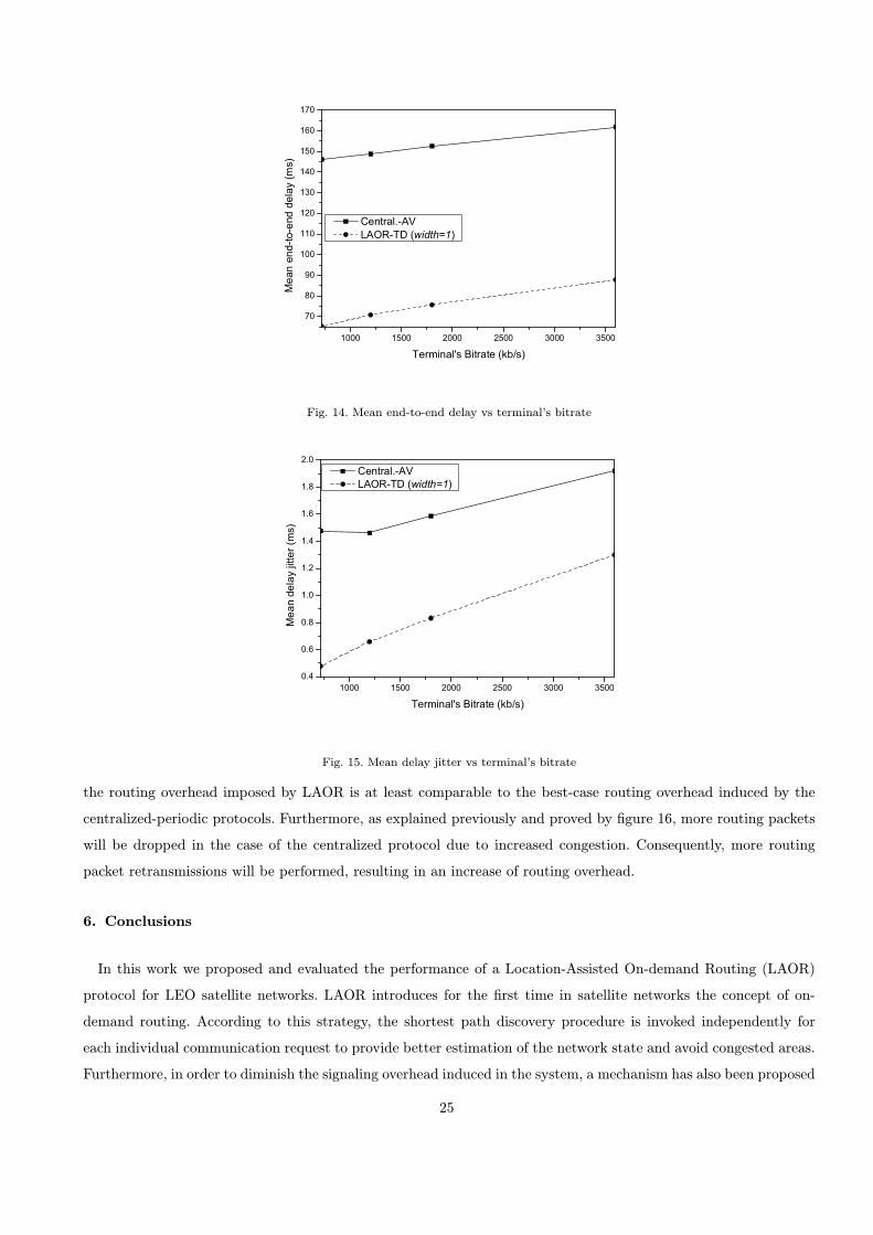
Fig. 14. Mean end-to-end delay vs terminal’s bitrate
Fig. 15. Mean delay jitter vs terminal’s bitrate
the routing overhead imposed by LAOR is at least comparable to the best-case routing overhead induced by the
centralized-periodic protocols. Furthermore, as explained previously and proved by flgure 16, more routing packets
will be dropped in the case of the centralized protocol due to increased congestion. Consequently, more routing
packet retransmissions will be performed, resulting in an increase of routing overhead.
6. Conclusions
In this work we proposed and evaluated the performance of a Location-Assisted On-demand Routing (LAOR)
protocol for LEO satellite networks. LAOR introduces for the flrst time in satellite networks the concept of on-
demand routing. According to this strategy, the shortest path discovery procedure is invoked independently for
each individual communication request to provide better estimation of the network state and avoid congested areas.
Furthermore, in order to diminish the signaling overhead induced in the system, a mechanism has also been proposed
25
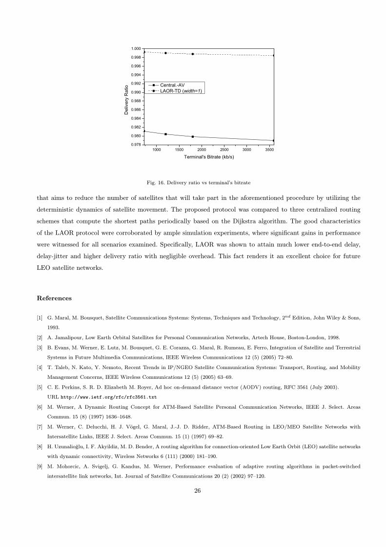
Fig. 16. Delivery ratio vs terminal’s bitrate
that aims to reduce the number of satellites that will take part in the aforementioned procedure by utilizing the
deterministic dynamics of satellite movement. The proposed protocol was compared to three centralized routing
schemes that compute the shortest paths periodically based on the Dijkstra algorithm. The good characteristics
of the LAOR protocol were corroborated by ample simulation experiments, where signiflcant gains in performance
were witnessed for all scenarios examined. Speciflcally, LAOR was shown to attain much lower end-to-end delay,
delay-jitter and higher delivery ratio with negligible overhead. This fact renders it an excellent choice for future
LEO satellite networks.
References
[1] G. Maral, M. Bousquet, Satellite Communications Systems: Systems, Techniques and Technology, 2nd Edition, John Wiley & Sons,
1993.
[2] A. Jamalipour, Low Earth Orbital Satellites for Personal Communication Networks, Artech House, Boston-London, 1998.
[3] B. Evans, M. Werner, E. Lutz, M. Bousquet, G. E. Corazza, G. Maral, R. Rumeau, E. Ferro, Integration of Satellite and Terrestrial
Systems in Future Multimedia Communications, IEEE Wireless Communications 12 (5) (2005) 72{80.
[4] T. Taleb, N. Kato, Y. Nemoto, Recent Trends in IP/NGEO Satellite Communication Systems: Transport, Routing, and Mobility
Management Concerns, IEEE Wireless Communications 12 (5) (2005) 63{69.
[5] C. E. Perkins, S. R. D. Elizabeth M. Royer, Ad hoc on-demand distance vector (AODV) routing, RFC 3561 (July 2003).
URL http://www.ietf.org/rfc/rfc3561.txt
[6] M. Werner, A Dynamic Routing Concept for ATM-Based Satellite Personal Communication Networks, IEEE J. Select. Areas
Commun. 15 (8) (1997) 1636{1648.
[7] M. Werner, C. Delucchi, H. J. Vogel, G. Maral, J.-J. D. Ridder, ATM-Based Routing in LEO/MEO Satellite Networks with
Intersatellite Links, IEEE J. Select. Areas Commun. 15 (1) (1997) 69{82.
[8] H. Uzunalio‚glu, I. F. Akyildiz, M. D. Bender, A routing algorithm for connection-oriented Low Earth Orbit (LEO) satellite networks
with dynamic connectivity, Wireless Networks 6 (111) (2000) 181{190.
[9] M. Mohorcic, A. Svigelj, G. Kandus, M. Werner, Performance evaluation of adaptive routing algorithms in packet-switched
intersatellite link networks, Int. Journal of Satellite Communications 20 (2) (2002) 97{120.
26
[10] M. Mohorcic, M. Werner, A. Svigelj, G. Kandus, Adaptive routing for packet-oriented intersatellite link networks: performance in
various tra–c scenarios, IEEE Trans. Wireless Commun. 1 (4) (2002) 808{818.
[11] I. F. Akyildiz, E. Ekici, M. D. Bender, MLSR: A Novel Routing Algorithm for Multilayered Satellite IP Networks, IEEE/ACM
Trans. Networking 10 (3) (2002) 411{424.
[12] H. S. Chang, B. W. Kim, C. G. Lee, S. L. Min, Y. Choi, H. S. Yang, D. N. Kim, C. S. Kim, FSA-Based Link Assignment and
Routing in Low-Earth Orbit Satellite Networks, IEEE Trans. Veh. Technol. 47 (3) (1998) 1037{1048.
[13] I. Gragopoulos, E. Papapetrou, F.-N. Pavlidou, Performance Study of Adaptive Routing Algorithms for LEO Satellite Constellations
under Self-Similar and Poisson Tra–c, Space Communications 16 (1) (2000) 15{22.
[14] E. Papapetrou, F.-N. Pavlidou, A Proposal of Optimal Routing Techniques for non-GEO Satellite Systems, International J. of
Wireless Inform. Networks 8 (2) (2001) 75{83.
[15] E. Ekici, I. F. Akyildiz, M. D. Bender, A Distributed Routing Algorithm for Datagram Tra–c in LEO Satellite Networks, IEEE/ACM
Trans. Networking 9 (2) (2001) 137{147.
[16] E. M. Royer, C.-K. Toh, A review of current routing protocols for ad hoc mobile wireless networks, IEEE Personal Communications
6 (2) (1999) 46{55.
[17] K. Fall, K. Varadhan, The ns manual, VINT Project, Univ. California, Berkeley, CA (2001).
URL http://www.isi.edu/nsnam/ns/ns-documentation.html
[18] M. Mohorcic, A. Svigelj, G. Kandus, Y. F. Hu, R. E. Sherifi, Demographically weighted tra–c °ow models for adaptive routing in
packet-switched non-geostationary satellite meshed networks, Comput. Networks 43 (2) (2003) 113{131.
[19] P. Gupta, P. R. Kumar, A system and tra–c dependent adaptive routing algorithm for ad hoc networks, in: Proceedings of the
36th IEEE Conference on Decision and Control, San Diego, California, 1997, pp. 2375{2380.
[20] S. Lohier, S.-M. Senouci, Y. Ghamri-Doudane, G. Pujolle, A reactive qos routing protocol for ad hoc networks., in: EUSAI, 2003,
pp. 27{41.
[21] D. Bertsekas, R. Gallager, Data networks (2nd ed.), Prentice-Hall, Inc., Upper Saddle River, NJ, USA, 1992.
27