
DISTRIBUTED BY: U. S. DEPARTMENT OF … BY: U. S. DEPARTMENT OF COMMERCE 5285 Port Royal Road,...
133
AD-759 685 HUMAN FACTORS ENGINEERING DESIGN OF AMMUNITION PRODUCTION LINE ROCKEYE MK20 John P. Jankovich Naval Ammunition Depot Crane, Indiana 31 March 1973 DISTRIBUTED BY: U. S. DEPARTMENT OF COMMERCE 5285 Port Royal Road, Spdnfield Va. 22151
Transcript of DISTRIBUTED BY: U. S. DEPARTMENT OF … BY: U. S. DEPARTMENT OF COMMERCE 5285 Port Royal Road,...

AD-759 685
HUMAN FACTORS ENGINEERING DESIGN OFAMMUNITION PRODUCTION LINE ROCKEYEMK20
John P. Jankovich
Naval Ammunition DepotCrane, Indiana
31 March 1973
DISTRIBUTED BY:
U. S. DEPARTMENT OF COMMERCE5285 Port Royal Road, Spdnfield Va. 22151

UNCLASSIFIED RDTR No. 239
31 March 1973
HUMAN FACTORS ENGINEERING DESIGNOF
AMMUNITION PRODUCTION LINE
* <ROCKEYE MK 20
Statement A: Approval for public release;distribution unlimited.
IDDC
MAY 10 19
~LP 11.U JnPREPARED BY
RESEARCH AND DEVELOPMENT DEPARTMENT
NAVAL AMMUNITION DEPOT, CRANE, INDIANAfttproducod by
~ NATIONAL TECHNICALINFORMATION SERVICE
U $ Deiporl nt of CommerceSp ingf~ld VAfl}iI
UNCLASSIFIED
•,•,V30

..
UNCLASSIFIED
DOCUMENT CONTROL DATA- R & D" la lcail It '.If . r . I.a I .t.ofa.ý rarat q.80 itt.I.xIII.' annoirUtthn fnllY h' ontre'd when thc ,,verelI rqport is..fIYII.t
I c '-Gý.,NA TING ACTIVITY (C"og.lpoate iaithor) 4a. REPORI SLCURI1Y CLASII ICAIION
Naval Ammunition Depot UNCrane, Indiana
3 R-POCRT TITLE
HUMAN FACTORS ENGINEERING DESIGN OF AMMUNITION PRODUCTION LINE ROCKEYE MK 2C
4 DESCRIP yVE NOTES (7"pe of report antd inclusive dates)
S. AU THOMIS) (First name, middle Initial, last name)
JANKOVICH, JAHN P.
6. REPORT DATE 7A. TOTAL NO. OF PAGES R17b NO. OF REPS
31 MARCH 1973 118 10Ee. CONTRACT OR GRANT NO. Oa, ORIGINATOR'S REPORT NUMOERI(SI
RDTR No. 239b. PROJECT NO.
9h. OTHER REPORT NO(S) (Any other nuhb/er that may be assignedthia report)
d.
10( DISTRIBUTION STYA EMENT
Dibtribution of this document Is unlimited.
11 %U•t-PLMENTARY NOTES o,?.. SPONSORING MILITARY ACTIVITYDetoils of illustrotiorts in
this document may be betterstudied on mlcroflcbe
i3 ABTSTRACT
"The man-machine interfaces are redesigned on an ammunition production assembly lineo provide the best possible human factors configuration of each work station. Machineryas to be redesigned to achieve Integration of the human and machines with emphasis on
he abilities, capacities, and limitations of the human body. Areas of human factorsngineering considered: personnel work space (equipment arrangement, seating, layoutf panels, etc.), materials handling (lifting, carrying, reaching, tools, etc.), physical
environment of personnel (illumination, ventilation, noise, vibration), design of controlsinformation input and output devices, location, size, spacing of switches, push buttons,ranks, levers, handwheels, etc.), and Industrial safety. Recommendations are based onvaluation of the human factors aspects of each work station, studied by the method of a.omprehensive checklist, production observation, and nperator interviews.
DD,'°".o...61473 . ' ' ....../ if-ph.• VNCLASFIFI6
Ct', C 1 ,87. 680i ¢urltTV .a855tsMii OR|•

LINK A LINK 8 LINK CKEY WORDS - -ROLE WT RO L. E5 WT ROLE WT
II
--. , • - --I- -
DD NovN 1473 (8A•)(PAGE 0) Security C18#1icaton
UNCLASSIFIED
NAVAL. AMMUNITION DEPOTCrane, Indiana
RDTR No. 239
HUMAN FACTORS ENGINEERING DESIGNOF AMMUNITION PRODUCTION LINE
ROCKEYE MK 2O
Statement A: Approval for public release;distribution unlimited.
31 MARCH 1973
PREPARED BY k4 T _ _ _ _ _
JOHeI P. JANKOVI tI, Ph.D., Research Engineer
RELEASED BY^ME M. PEAY, ,Manager, Hum acor Division
RESEARCH AND DEVELOPMENT DEPARTMENT
UNCLASSIFIED
I

RDTR No. 239
INTRODUCTION
Human factors engineering is the field of science aimed at creating
the optimal relationship between man and his working environment. The
term environment in this sense Involves not only the ambient atmosphere,
but tools and materials, methods and organization of work, which are all
related to the man himself, to his abilities, capacities and limitations.
The objective of this study was to redesign, according to the principles
of human factors engineering, the man-machine interfaces at the work
stations of an ammunition production lIne, assembling Rockeye Mk 20
bombs. The report intends to provide recommendations to supervisors
in charge of the operation. The data are 9iven in a condensed form of
listed suggestions, applicable for Immediate Implementation.
Consequently, the theoretical aspects of the involved problem areas are
covered less extensively.
Good human factors design In an Industrial process affects two important
aspects of production. First, stresses to which the human body Is
unwittingly subjected over a long period may cause loss of efficiency
or create unnecessary safety hazards in the short term and disability
later In life. Secondly, failure to match requirements of a task with the
capabilities of the operator may cause reduced output and, in the extreme
case, disaster.
A large body of information is available on human factors engineering
design of work places. To put these data to work, translation is needed into
the facts of industrial life. Therefore, this report presents primarily
ii

RDTR No. 239
recommendations only In a readily implementable form. The study intends
to provide suggestions for immediate use on the existing assembly line
without introducing drastic changes in technology of the established
manufacturing process. However, reasons for the recommendations are
given in condensed form to explain the underlying theoretical background.
Thus the first part of each recommendation describes the changes necessary
for fitting the task requirements to human capabilities. The second part of
most of the suggestions presents some Insight into the scientific bases which
underlie them. Additional data are available in a number of handbooks
which contain human factors information In a form suitable for applied
implementation (References 1, 3, 9, 10). Relevant military standards are
also available on human factors design of equipment (References 2, 4, 5).
In the development of the human factors checklist of work stations, pertinent
military test procedures were utilized (References 6, 7, 8).
The recommendations were derived from the combined findings of (I)
production observation by human factors engineers, (2) evaluation of a human
factors checklist and (3) interviews with production line personnel and
supervisors. In this multiple method of data collection, each technique
concentrated on the following aspects of man-machine Interface design:
personnel work space (work space arrangement, seating, layout of
controls, control panels, etc.), materials handling (lifting, carrying,
reaching tools, etc.), physical environment of personnel (illumination,
ventilation, noise, vibration), design of controls (information input and
output devices, location, size, spacing of swtiches, push buttons, cranks,
levers, handwheels, etc.) and Industrial safety. The Appendix of this report
iii

RDTR No. 239
contains the checklist which was used to evaluate every work station of
the assembly line.
This study was supported by the Resources and Planning Department,
Naval Ammunition Depot, Crane, Indiana. In compilation of the data, the
assistance given by Mr. S. Armstrong, Program Manager of Rockeye
Production, and Mr. R. Moody, General Foreman, Ordnance Department,
is gratefully acknowledged and appreciated.
alv

RDTR No. 239
TABLE OF CONTENTS
PAGE
Abstract ......... ...........................
Introduction . .......................... ii
Human Factors Analysis of Work Stations ............. I
Work Station A-5 ........ ...................... 1
Work Station A-6 ..................... ... ... ... 4
Work Station A-7. . ...................... 4
Work Station A-9 . . . . . . ....................... . .. .. ......... 5
Work Station A-10 ........ ...................... 5
Work Station A-.1 13....
Work Station A-11 ............ . ....................... . . 15
Work Station A-13 ...................... .. ... 18
Work Station A-16..................... . . ..... 822
Work Station A-17. .. ................. ... . 24
Work Station A-1 . . . . . . . . . . . . . . . . . .. . . . 24
Work Station A-21 . . . . . . . . . . . . . . . . . . . . . 25
Work Station A-24 . . . . . . . . . . . . . . . . . . . . . 29
Work Station A-20 . . . . . . . . . . . . . ,...... . 31
Work Station A-30 . . . . . . . . . . . . . . . . . . . . 35
Work Station A-33 . . . . . . . . . . . . . . . . . . . . 37
Work Station A-34 . . . . . . . . . . . . . . . . . . . . . 40
Work Station A-35 . . . . . . . . . . . . . . . . . . . . . 43
Work Station A-37 ............. . . . .................... 143
v

RDTR No. 239
Work Station A-38 ......................... 44
Work Station A-42 .............................. 48
Work Station A-43. . ....................... 55
Work Station A-44 ............................... 60
Work Station: Tray Repair ......................... 67
Work Station: B-I .............................. 73
Work Station: B-5 ........ ...................... 75
Work Station: B-6 .............................. 77
Work Station C-2 ................................ 81
Work Station C-5 . ............................. 85
Work Station C-6. ............................... 87
APPENDIX .......... ... ... ........................... .... 89
REFERENCES ........ .......................... 118
V1

RDTR No. 239
LIST OF ILLUSTRATIONS
PAGE
Figure I. Work Station A-5: Turning Bomblets ........ 2
Figure 2. Design of Handwheels ..................... 3
Figure 3. Protective Shield ....................... 6
Figure 4. Work Station A-9: Bomblet and tray assembly . 7
Figure 5. Work Station A-5: Pouring of Explosive ... 9
Figure 6. Recommended New Work Place Arrangement . 10
Figure 7. Work Station A-10: Pouring of Explosive..... 12
Figure 8. Work Station A-11: Cooling of explosivtý ...... .. 14
Figure 9. Work Station for Removing Bolts ............. 16
Figure 10. Location Where Guides are qeeded on Tray .... 16Conveyor
Figure 11. Work Station A-12: Removing Bolts from . . . . . 17Tray Assembly
Figure 12. Work Station A-13: Pouring Tray Removal . . . . 19
Figure 13. Recommended shape-coding of press levers . . . 21
Figure 14. Work Station A-16. Removing bomblets from . . . 23Tray
Figure 15. Work Station A-21. Bomblet cleaning ...... 26
Figure 16. Work Station A-21: Bomblet cleaning and .... 27Recuptacles
Figure 17. Work Station A-24. Drilling Booster Assembly . . 30
Figure I8. Assignment of operators and location of . . . . . . 32emergency switches
Figure 19. Work Station A-28, Placing Bornblets on .... 33conveyor
Ai

RDTR No. 239
Figure 20. Work Station A-30. Sealing Booster Assembly . , 36
Figure 21. Work Station A-33. Crimping Tail Fin on . . . 38Bomblet
Figure 22. Recommended new location of actuator ...... .39
Figure 23. Work Station A-34: Crimping Sensing Element. , 41
Figure 24. Activating trigger arm should be mounted 300. , 42off vertical for ease of operation on crimpingmachine
Figure 25. Work Station A-38: Preparation of cargo section. 45
Figure 26. Concept of a packing strip installation ...... .46
Figure 27. Design of Toggle Switch ................. 49
Figure 28. Activation Surface of Push Buttons .......... 49
Figure 29. Design of Control Levers ................. 51
Figure 30. Work Station A-42: Pressure testing of bomb . , 52assemblies
Figure 31. Work Station A-42: Bracket is needed to hold , 54pressure hose.
Figure 32. Work Station A-43: Closing bomb shipping . . . 56
container
Figure 33. Undesirable effect of lumbar disc when lifting 57
Figure 34. Work Station A-44. Banding of containers . . 61
Figure 35. Clearance for body positions ............... 62
Figure 36. Proposed Work Space Arrangement . . . . . .. 63
Figure 37. Work Station A-44: Palletizing operation .... 64showing excessive bending.
Figure 38. Suggested configuration of brace . ....... 65
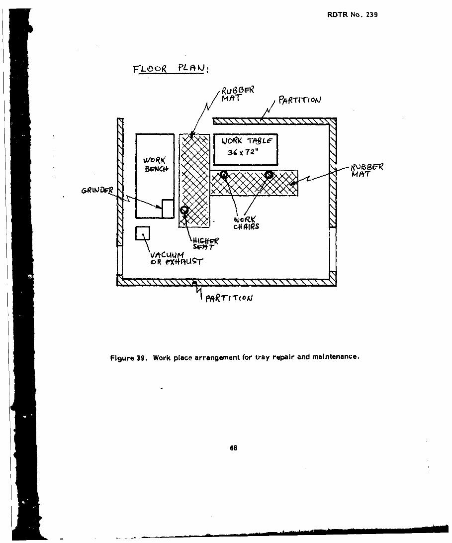
Figure 39. Work place arrangement for tray repair ...... 68
viii
RDTR No. 239
Figure 40. Recommended dimensions for work tables . . . . 69
Figure 41. Dimensions of a good chair for seated ...... .. 69operations
Figure 42. Dimensions of a gbod chair for alternating . . . . 69seated and standing operations
Figure 43. Arrangement of Lighting Fixtures ........... 72
Figure 4A4. Supplementary light near the work area. 72
Figure 45. Work Station B-5. Unloading explosive ..... .76from conveyor.
Figure 46. Suggested modifications for Work Station B-6 . . 78
Figure 47. Recommended dimensions for ladder design . . . 80
Figure 48. Handralls on both side of ladder with non-slip. 80surfacing
Figure 49. Work Station G-2: Present method of inspection . 82
Figure 50. Layout of how an inspection station should be . 82built
Figure 51. Work Station C-5: Assembling booster units . . 86
Figure 52. Work Station C-6: Operation of crimping press . 88
ix

RDTR No. 239
HUMAN FACTORS ANALYSIS OF WORK STATIONS
Recommendations to improve human factors design of individual work
stations are listed in this chapter. The suggestions are obtained by critically
reviewing the checklist (enclosed in the Appendix) for each operation and
scrutinizing findings of work station observations and interviews with
workers and management. Recommendations are listed -in increasing order
of importance. Overlapping areas are discussed under one heading.
Work Station:- A-5
Turn Bomblets and Tray Assembly
a. Provide more positive stop on turning motion of turn table.
Many operators have difficulty in stopping turn table lined up with conveyor.
As a result, with trial and error they move table back and forth until
right position is found.
b. Provide recessed hand grips on turn table. Presently, only a few
holes are cut along wheel circumference for the fingers to grip the
turntables firmly, Figure 1. Grip holes should be placed all around the
circumference of the end plates on each side or a contoured rim should be
used.
Ideal design of handwheels Is shown in Figure 2. Contour molding
is strongly recommended on the handwheel rim to aid in holding it.
A wheel diameter between 12 and 21 Inches Is suggested, rim diameter
can vary between 0.75 and 2 inches, resistance between 5 and 30 lbs.

RDTR No. 239
Figure 1. Work Station A-5: Turning Bomblets and tray assembly. Handwheeldoes not have good gripping surfaces. The other operator mustbend excessively because bolt bin is 6"1 too low.
2
a --

RDTR No. 239
d,
Figure 2. Design of Handwheels
d: 0.75-2 Inches
D: 12-21 Inches
Force: 5-30 Pounds
3

RDTR No. 239
c. Provide a quick release stop in front of turn table In order to prevent
tray assemblies from sliding onto the turn table when they pile up on conveyor.
The operator frequently mUst push several tray assemblies back on conveyor
to be able to rotate turn table.
d. To ease operation, sliding surface on turn table should be replaced
with rollers, resembling a roller conveyor. The upper photograph in Figure
1 shows the operator spraying the sliding surface with lubricant to reduce
friction. Force requirement will be greatly reduced with the application
of rollers and time will be reduced to complete the task.
Work StaUon: A-6
Secure Bomblets and Tray Assembly
a. The lower photograph-in Figure 1 shows that operator has to both
bend and twist to the left in order to reach clamp bolts. Bolt container
should be raised 6 inches higher above its present level to eliminate
, unnecessary bending motion.
Work Station: A-7
Grease Pouring Heads
a. To protect eyes from light of preheater, place a protective shield
over conveyor IZr front of preheater entrance. Size of the opening on
shield should be just large enough for tray assemblies to pass.
b. Mark hot surfaces on preheater with warning labels to prevent
accidents.
14
L

RDTR No. 239
NOTE: Figure 3 shows how the above recommendations had been implemented
by the time this report was finished. Rubber flaps around entrance shield
shade heater light completely and warning signs show hot surfaces.
Work Station: A-9
Bomblet and Tray Assembly Removed from Preheater
a. Raise legs of receiving bin for pouring covers 8" higher in order
to avoid unnecessary bending when operator brushes them clean.
NOTE: Figure 4 shows how the above recommendation had been implemented
by the time this report was finished. The operator's bending motion is
greatly reduced.
Work Station: A-10
Pouring
a. The operator constantly adjusts six push-pull valves to regulate
proper flow of explosive. Five valves increase flow when pushed, the
sixth valve operates conversely, which Is unacceptable. Furthermore,
the steel valve shafts tend to bind to the aluminum bushings as usedJ
presently, which makes continuous regulation of flow extremely diffic.,,t,
and results in stepwise jerks of adjustment. The operator has to remove
the protective gloves 4-5 times. a minute in order to adjust the flow.
Recommendation for Immediate action:
(1) All valves must operate In the same direction.
(2) Decrease friction by using bronze bushings.
Recommendations for long-range planning: convert the linear regulating
action to circular motion using a pear assembly. In such a configuration
5

RDTR No. 239
Figure 3. Protective shield has been mounted around preheater entranceto eliminate glare. Hot surfaces have been marked. Thelowest 3rrow Indicates Improper method of Identifying controlvalves with a loose paper label.
6

RDTR No. 239
Figure L4. Work Station A-9: Bomblet and tray assembly reimoved frompreheater. Height of receiving bin has been raised and bendingof the operator's back reduced.
7

RDTR No. 239
the flow should increase by turning regulating wheels in clockwise
direction, with the wheels facing the operator. A less preferable but still
good solution could be achieved by placing the regulating wheels in the
center plane of the operator and increasing the flow when the top of the wheel
is moved away from the worker.
b. Auxiliary light sources are needed to provide proper illumination
under the kettle and In cabinet where proper height of explosive level is
adjusted (and pouring cover is removed). The lights should be mounted
on the side wall to provide adequate illumination under the equipment.
Presently, operators complain that they cannot see well.
c. Height of work platform should be lowered 8-10", because presently
the operator has to bend to be able to see the pouring level, located only
18" above the walking surface, see Figure 5. Work place arrangement
with the recommended lower level walking surface is shown in Figure
6. Height of receiving bin at Work Station A-9 should be equal to height
of this work surface, as illustrated.
d. Provide a good seat for the operator. A swivel seat is
needed which should have cushioning, backrest, and height adjustment
between 12-24". Presently, a 10" backless steel stool Is used on which
the workers themselves taped some foam rubber for comfort. Requirements
for good work chair design are described later, for work station: Tray
Repair. Figure 41 shows recommended chair dimensions and necessary
adjustments to accommodate anthropometric differences. Roller casters
should not be used on elevated work surfaces.
8

RDTR No. 239
W~
7
---- F
Figure S. Work Station A-5. Pouring of Explosive. Work platform is elevatedtoo high, the opoi•ator has to bend excessively In order to be ableto observe the work process. Platform surface should be lowered8-10".
9

RDTR No. 23.9
FLUORESCENT
FLOW ALVESLIGHT FIXTURE
FLOW ALVESTOP OF COVER
ASSEMBI IES
CONVEYOR KETTL
FLOOR
RAISE RECEIVING LOWER WALK ELIMINATEBIN SURFACEs PROVIDE WALKWAY
SWrVEL CHAIR
SIDE VIEW
Figure 6. Recommended new work place arrangement for pouring ofexplosives with raised receiving bin, lowered walk surface,eliminated walkway, built-in fluorescent light for WorkStations 9, 10, and II.
10

RDTR No. 239
NOTE: Good seats had been acquired by completion time of this report, as
shown in Figure 5.
e. Control Panel. Separate the controls belonging to kettles A and B
by color coding on the control panel, and on the regulating handwheels.
Presently, a single letter mark, as indicated In Figure 7, differentiates
one control function from the other. It is suggested that color be used
to code functions: one side of the panel and all corresponding valves,
handwheels, etc., could be painted one color, while the other half and its
valves and handwheels be identified with another color.
Use higher Intensity bulbs in control panel indicators, because they
are hardly visible. Use engraved plates to identify controls on panel
Instead of tapes. Label both emergency stop and conveyor speed regulator
(their location and design is satisfactory). Speed regulator arm and housing should
be painted with the warning yellow color. Label vibrator pressure gauges,
cover plastic air pipes to protect them from damage (operators step on them
sometimes when climbing on top of vibrator). Mark norsnal operating range
on pressure gauges. Some electric cords are loose on back of control
panel, they should be concealed. Eliminate the two unconnected signal
lights mounted on the panel.
f. Label hot surfaces on vibrator. Label emergency stop switch.
g. One pipe on ceiling is sweating In cold weather, dripping condensed
water on workers and walkway. Proper Insulation Is needed,

RDTR No. 239
Figure 7. Work Station A-10: Pouring of Explosive. Inadequate identificationof control functions A and B should be Improved by color codingthem on the control panel and by similarly color marking theircorresponding controls.
12

RDTR No. 239
Work Station: A-11
Cooling
a. Eliminate elevated walkway used for correcting explosive levels.
Presently a two-step high platform is used providing a work surface 36"'
above the walking surface. This is low; the operator has to bend in
order to be able to reach under the protective cover of the machine, Figure
8. Elimination of the walkway and lowering the platform of A-10 will provide
a similar workplace arrangement to the present configuration but with the
assurance of proper height of the work areas. Outline of this new lowered
work space arrangement is shown in Figure 6, where both Work Station
A-10 and A-11 are illustrated as related to each other.
b. To provide adequate illumination over tray conveyor under heat
protective cover, fluorescent lightc should be mounted on top of machine.
An opening of the size of the light fixture could be cut in the cover plate
and the fixture mounted directly on the cover plate. Figures 6 and 8
illustrate where light fixture Is suggested to be Installed. Tight seals
between the edges of the cover plate opening and the light fixture will
prevent heat escape and installation of the luminaire will not influence
the present heat balance,
13

RDTR No. 239
Lorcation"OI!•:• , light fixture
Figure 8. Work Station A-Il: Cooling of explosive. Undesirably highwalkway forces operator to bend excessively when attendingmachine. Walkway should be ;owered. A fluorescent fixtureshould be mounted directly on cover plate to provide adequateillumination under machine top.
14

RDTR No. 239
Work Station: A-12
Remove Bolts From Tray Assembly
a. Assembly trays should be stopped at end of conveyor II, not 4" behind
as done presently, The operator has to push each tray back to position them
on conveyor II. See Figure 9.
b. This work station could be easily converted Into seated operation.
The necessary knee space could be provided by changing only the tray
under conveyor II. See Figure 9.
c. Operator complains about vibration pain In right hand and wrist due
to use of impact wrench. Figure 11 illustrates work position of the operator.
The right hand Is unevenly overloaded with respect to the left hand.
Recommendation: modify wrench suspension to make left hand operation
possible so that the worker could alternately use either right or left hand.
Use a wrench with largor mass, to take advantage of the larger inertia
of a heavier tool to reduce vibration intensity.
d. Work level is high. Even though an elevated platform is provided for the
operator, Its height Is still not sufficient. Figure 11 shows how operator
Is forced to work with raised arms and shoulders well above optimal (and
* normal) position. Height of work surface should be 36 to 40"t above standing
surface. Use of higher work platform Is recommended.
e. Provide solid side rail and guide plate on conveyfor II, as indicated In
Figure 10 (the present rail is broken, and trays often get stuck during rolling).
f. Use a power-driven conveyor instead of the present roller conveyor II.
Major effort is needed by A-12 to push trays over to next work station.
15 lei

RDTR No. 239
ASSEMLIESCONVEYOR 11
MODIFIED BUMPER
BUMPERee --. i
COVEO I TRAY
r1 NMODIFIED TRAYFOR SEATING
SIDE VIEW
Figure 9. Work Station for Removing Bolts from Tray Assembly, A-12
CONVEYOR II
LOOSE RAIL
PROVIDE GUIDE (ASSEMBLIESHIT RAIL.)
- A-12 STATION
TOP VIEW
Figure 10. Location Where Guides are Needed on Tray Assembly Conveyor,
Work Station A-12
16

RDTR No. 239
Figure II. Work Station A-12: Removing Bolts from Tray Assembly.Right hand of operator is overloaded. Air wrench shouldbe modified for possible left hand operation. Work levelis excessively high: elbows and arms are kept raised.Operator should be standing at a higher level.
17
ho

1- -,-
RDTR No. 239
Work Station: A-13
Pouring-Tray Removal
a. Conveyor between work stations A-13 and A-16 (the next stop) should
be power-driven. The operator presently spends 25-30% of his time pushing
and forwarding tray assemblies on the conveyor and lubricates rollers
frequently to reduce the necessary physical effort. Both photographs in
Figure 12 show the operators transporting tray assemblies to next work
station on roller conveyor.
b. Passageway between work stations A-13 and conveyor leading to A-14
is 11 Inches wide, providiog inadequate clearance. Figure 12 shows the difficulty
which operators experience when they try to squeeze, into the passageway in
order to be able to forward tray assemblies to next work station. Five more
inches could be added to this space by removing protruding ends and the
first unused roller from conveyor.
c. Operator lifts and removes pouring trays from press at a height
of 54 1/2". This is too high for most operators, Figure 12. An elevated
platform is recommended in front of the machine height 10-14". An 8" high
platform is available and used, but is still not sufficient anthropometr!cally.
The working surface must optimally be 36" above standing level. Note,
however, that location of activating switches will be too low when such
an elevated platform is used. Therefore, switches must also be raised
proportionally to a higher level.
d. Label air valves and use shape coding on valve handles for ease of
identification. Shape coding Improves visual and tactile identification
18 .

RDTR No. 239
--ihworking l~evel
Figure 12: Work Station A-13: Pouring-Tray Removal. Operators haveto squeeze through II" wide passageway in order to be ableto forward trays to next station. High working level can beImproved with higher standing platform.
19

RDTR No. 239
of controls. When feasible, it is desirable to select functional shapes that
suggest the purpose of the control. Design of the shapes must be highly
discriminable.
Shape coding is recommended for this work station, because operator
activates machine without really looking at control levers. Presently, the
only feedback information which he uses to identify the right control is the
spatial location. If knobs of different shapes are used, the operator is
provided with an additional channel of information for correct identification
of functions. Figure 13 shows recommended knob shapes. The vertical
block is intended to indicate vertkcal lifting action, while the spherical
shape should differentiate all-directional grasping from lifting.
e. Renew worn-off paint on moving surfaces: both on grabbing heads
and on lifting heads.
IAIM

_ _ : I
RDTR No. 239
DIAS1 3/4 " 2 --"
SPHERE FOR BLOCK FORGRASPING ACTION LIFTING ACTION
Figure 13. Re-ommended shape-coding of press activating levers.
Shape-coding Ipmyroves vi~sual and tactile identification
of functions -for Work Station A-13.
21
RDTR No. 239
Work Station: A-16
Remove Bomblet from Tray
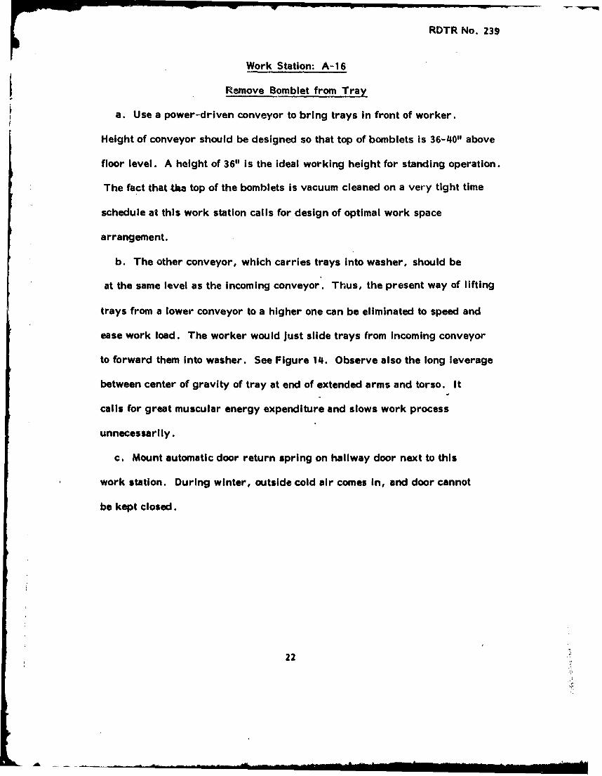
a. Use a power-driven conveyor to bring trays in front of worker.
Height of conveyor should be designed so that top of bomblets is 36-40" above
floor level. A height of 36" is the ideal working height for standing operation.
The fact that tka top of the bomblets is vacuum cleaned on a very tight time
schedule at this work station calls for design of optimal work space
arrangement.
b. The other conveyor, which carries trays into washer, should be
at the same level as the incoming conveyor. Thus, the present way of lifting
trays from a lower conveyor to a higher one can be eliminated to speed and
ease work load. The worker would just slide trays from incoming conveyor
to forward them into washer. See Figure 14. Observe also the long leverage
between center of gravity of tray at end of extended arms and torso. It
calls for great muscular energy expenditure and slows work process
unnecessarily.
c. Mount automatic door return spring on hallway door next to this
work station. During winter, outside cold air comes in, and door cannot
be kept closed.
22

RDTR No. 239
Figure 14, Work Station A-16: Removing bomblets from tray, Bothconveyors should be at equal level so that operator couldtransfer trays from one conveyor to another by pushingthem sideways. Observe undesirable large leverage batweentray in the extended arms and torso. This arrangement callsfor excessive muscular force exertion.
23

RDTR No. 239
Work Station: A-17
Place Tray Assembly in Wash
a. The two emergency switches should be labelled and specified
by function, such as:
(1) "Stop Steam" or "Steam Off" and
(2) "Stop Conveyor". Plane of switches and labels should face
operator.
Work Station: A-18
Remove Tray Assembly from Wash
a. Cover return conveyor with protective plate under level of top
surface. Label emergency switch on return conveyor.
b. Label emergency switches of washer conveyor on each side so that
it Is visible from all working positions.
24
RDTR No. 239
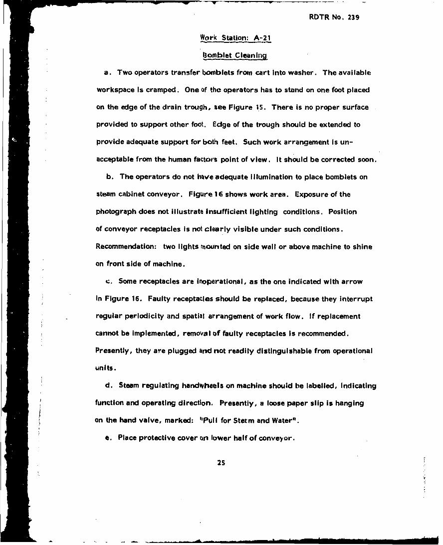
Work Station: A-21
1omblet Cleaning
a. Two operators transfer bonblets from cart into washer. The available
workspace is cramped. One of the operators has to stand on one foot placed
on the edge of the drain trough, see Figure 15. There is no proper surface
provided to support other foot. Edge of the trough should be extended to
provide adequate support for both feet. Such work arrangement is un-
acceptable from the human factors point of view. It should be corrected soon.
b. The operators do not have adequate Illumination to place bomblets on
steam cabinet conveyor. Figure 16 shows work area. Exposure of the
photograph does not illustrate insufficient lighting conditions. Position
of conveyor receptacles is not clearly visible under such conditions.
Recommendation: two lights mounted on side wall or above machine to shine
on front side of machine.
c. Some receptacles are inoperational, as the one indicated with arrow
in Figure 16. Faulty receptacles should be replaced, because they interrupt
regular periodicity and spatial arrangement of work flow. If replacement
cannot be implemented, removal of faulty receptacles is recommended.
Presently, they are plugged and not readily distinguishable from operational
units.
d. Steam regulating handwheels on machine should be labelled, Indicating
function and operating direction, Presently, a loose paper slip is hanging
on the hand valve, marked: "Pull for Sterm and Water".
e. Place protective cover on lower half of conveyor.
25

RDTR No. 239
' an,
Figure 15. Work Station A-21: Bomblet cleaning. Operator stands onone foot. Other foot is unsupported, an unacceptably tiresomework position.
26

RDTR No. 239
Figure 16. Work Station A-21: Bomblet cleaning. Bomblet receptacles.are not illuminated properly (exposure of photographscompensated this). Some receptacles are inoperationaland plugged as the one shown with arrow, but not readilydistinguishable from the others. Such arrangement interruptsperiodicity and regular spatial arrangement of work flow.
27

RDTR No, 239
f. Label emergency switch on output end of washer conveyor.
g. For Iong.,range planning, it is recommended to transform A-21
work stations at the receiving end into seated operations. The trays carrying
the bomblets could come on a conveyor, which would carry trays or Individual
bomblets right to the top of the feeding conveyor of the washer.
28

JW -
RDTR No. 239
Work Station, A-24
Drill Booster Assembý.
a. Mount a leaning plate in front of operator to support body above
conveyor. Presently, the operators support their body by leaning with
their thighs against the side of the conveyor frame and stiffening their
mjscles, as shown in Figure 17. The supporting surface could be extended
by mounting a plate on the frame of conveyor stand. The plate should be
padded. Maximum height of upper edge of the leaning plate Is suggested to
be 33.5" above floor level. Such a height accommodates anthropometric
elbow height of 95% of the female population.
b. Label hydraulic switch. A position switch with labelled on-off
positions Is preferable to the present push button of the air switch. The
worker cannot Identify on-off conditions of the machine by looking at a push
button, Label emergency switch also such as "Emergency Stop".
29

RDTR No. 239
fopQ
Figure 17. Work Station A-24: Drilling Booster Assembly. Supportsher body by leaning against conveyor and stiffeningabdominal muscles. Provide a padded leaning plate infront of operator to support weight of torso above conveyor.
30
AL. .. .. .. ,• . • ,. . • • , 1 •, • p =• ' • - " • I 1 I I I- I • = i •

RDTR No. 239
Work Station: A-28
Place Loaded "Bomblet on Assembly Conveyor
a. One of the three workers performing this function puts separating
wooden blocks between bomblets on conveyor. This work station is located
In Bay A, Line 1, where already two other workers are positioned. The work
space is crowded, free and easy emergency exit for the three workers is
blocked with delivery carts. Recommendation: wooden blocks should be put
on conveyor in Bay B, Line 1 that is right at the other side of the wall separating
the two bays. The cart supplying the wooden blocks should be in Bay B also.
No changes on conveyor or in other work stations are required. See Figure 18.
b. The three workers have one emergency switch only. It is a flip-flop
type switch with the "on" position downwards. Label switch, use several
switches if possible, with the "on" position up. By completion time of this
report, correct labeling has been executed, as shown in Figure 19.
c. LOCATION OF EMERGENCY STOP SWITCHES ON ASSEMBLY CONVEYORS I 2.
This comment concerns the whole operation of the two assembly lines.
Presently, there are emergency turn-off switches at stations A-28 and A-35 only
on the whole assembly line, as shown in Figure 18. Frequently, however,
the line has to be stopped for reasons originated at the other work stations
in-between. Voice communication is being used, transmitted from one worker
to the other in the extremely noisy environment of three bays where a large
number of crimping machines are working. Similarly, the line is restarted with
voice communication from work station A-35. There are even separating walls
between the bays with openings for the conveyor only. Recommendation:.
31

RDTR No. 239
BAY A BAY B BAY C
OPERATOR A-35.- RELOCATE BLOCK LAYER • MERGENCYA-28 AND CART
EMERGENCY STOPSTOP
CT CART CATCONVEYOR
OPERATOR
TOP VIEW OF LINE 1
Figure 18. Assignment of operators and location of emergency switcheson bomblet assembly conveyor.
32
NkL>-
RDTR No. 239
Figure 19. Work Station A-28: Placing bomblets on conveyor.Inadequate seating accommodations: no back rest,
no height adjustment, no foot rest are provided.Adjustable, padded swivel chairs should be used,as shown in Figure 42.
33
RDTR No. 239
each work station must be supplied with an emergency stop from A-28 through
A-35, because voice communication is slow and unreliable in the high ambient
noise environment. Restart should take place from one work station, A-35
only, as presently done, in order to ensure that all workers are safe for
start and conveyor is not started carelessly or accidentally.
d. Seating accommodation is inadequate. Operators sit on edge of chair,
or raise foot up to seating surface In trying to find a somewhat more
comfortable position as illustrated in Figure 19. Good chairs are very important
for good posture control. Proper support of the back prevents fatigue over
extended periods of time spent in the chair during a normal shift. Chair
height and back rest should be adjustable, provide swivel motion in the
seat pan, and have sufficient padding in the seat shown in Figure 42. When
purchasing a seat, order a more pleasing color than black.
34

RDTR No. 239
Work Station: A-30
Seal Booster Assembly
a. Use professional sealant dispensers instead of ketchup bottles.
Such dispensers do not require constant, high pressure static muscular
contraction force to operate and provide even, unclogged flow. See Figure
20.
b. Seating Is inadequate, Figure 20. See comments on seating for
Work Station A-28, Recommendation (d).
35

RDTR No. 239
Figure 20. Work Station A-30: Sealing Booster Assembly. Sealantdispenser requires continuous static muscular contraction,which is undesirable. Seating is inadequate: no padding,no height adjustment, no swivel action,
36

RDTR No. 239
Work Station: A-33
Crimp Tail Fin and Base Fuze Assembly to Bomblet
a. Crimp activating switch is located in the 12 o'clock position on the face of
the machine. This location complicates the operator's arm movements on
Line I unnecessarily, Figure 21. Positioning the switch in the 9 o'clock
position would simplify arm movements, eliminate twisting of the wrist,
and reduce the distance needed by operator to reach for bomblet by 18
inches. Technically, changing location of switch is simple, requiring
bending of one pressure line only.
b. The crimp release switch should be grouped together with the
activator switch. Presently, the release switch is completely Ineffective
because it takes lunger to move the hand from the activator to the release
switch, than for the duration of the whole crimping process. Therefore,
the release switch should be 3-4" above the activator (which should be
in the 9 o'clock position, as explained above). See Figure 22. Label
release switch.
c. Label air pressure shut off valve.
37

RDTR No. 239
Figure 21. Work Station A-33: Crimping tail fin on bomblet. Startbutton is positioned improperly: operator has to lift theleft hand high, out of smooth sequence of other handmotions. The start button should be in the 9 o'clockposition.
38

RDTR No. 239
NEW LOCATIONOF CRIMP RELEASE
ACTUATOR SWITCH
START-STOP FACE PLATE
CRIMPRELEASE
-NEW LOCATION OF ACTUATOR
Figure 22. Recommended new location of actuator and crimp release"switches on face plate of tail crimping machine,Work Station A-33
39
S. . . .. . . . . . ., •. - . i : , • - I • 1 - I I I I I •' 1

RDTR No. 239
Work Station: A-34
Install and Crimp Sensing Element
a. Sensing element crimper is mounted at a 450 angle to the direction
of motion of the conveyor. It is extremely inconvenient to operate the machine
in this position, Figure 23. The operator has to twist the lower arm to
reach the bomblet, when feeding it into crimper. Most operators pull
the activating lever with lower arm turned outside and with the thumb
pointing down. The angle between machine front plate and direction of
assembly line should be reduc-d to 300, exactly like the fin crimping machines.
Definite simplification of hand movements can be expected. It is recommended
to implement this suggestion first, and after observing operation, proceed
to recommendation "b", below. It is possible that recommendation "b" might
not be needed after the machines have been mounted at 300.
b. A 5-inch lever Is used to operate the machine. It Is in a vertically
downward position. Some operators use left hand, others use right hand
to activate the machine. The vertical position of the lever on Line 1, however,
is awkward in either case. Therefore, it is recommended to position the
lever 300 off vertical to the left, as shown in Figure 24. Such a position
would simplify hand movements for either left or right hand operation.
Vertical position of the lever is satisfactory on Line 2.
40

RDTR No.. 239
0.
4,0>
4)
0) 0W z
0)c
41.
RDTR No, 239
FACE PLATE
TRIGGER ARM
CONVEYOR
300
Figure 24. Activating trigger arm should be mounted 300 off verticalfor ease of operation on crimping machine, Work StationA-34
42.
ROThR No, 239
Work Sttion• A-35
Receive io Stock ._.blet,
a, Limit switch Is labelled with a paper slip only, Prepare perminont
label,
b, Emergency switch of stencil machine can be operated by another
worker, A-35 only, because the switch Is located at the other side of the
machine, If A-36 wants to stop the stencil machine, the limit switch,
designed for ovorload use only, must be kept pushad dnw•. Release of the
switch starts machine anew, Such a feature Is undesirable for stops, therefore,
application of another shut-off switch is recommended,
Work Station, A-37
Move2 sack to Pressing_ Machine
a. Wheels of the assembly carts ocusslailly have been lubricated, and
thus pushing the carts takes considerably mors effort than necessary and
hinders maneuverability significantly. Safety and smoothness of the
operation are affected, It should be somebody's responsibility to
lubricate cart wheels periodically.
43
llAll

K'ul M NO, 13V
Work Statlont A-34
PrLeopre Cargo Section
a, Use of flashlights to illuminate Inside of cargo section assembly
Is most Inadequate and time consuming, The worker has to hold and
direct flashlight with one hand and work with the other, See Figure 25,
Recommendatlon. use adjustable garage lights hanging from the coiling.
The lights should stop at any height above the floor, as required, With a
clip m•chanlism, the lights could eailly be mounted on the cargo section
and disconnected from it. Four or more lights are recopimendedJ to be
Installed,
b. General Illumination Is inadequate in this area, Two or more
overhead fluorescent lighting fixtures phould be suspended above the work
station.
c, Packing strip installation tool is complicated to use, It releases
frequently. A new design Is recommended which achieves prissure with
screw-and-cramnking action, The worker would Insert a cranking arm
into a rectangular receptacle and screw the pressing heads tight. An outline
of the concept Is presented In Figure 26,
d. Provide a tool shelf along wall for storage of handtools, 36"1 above
floor level. Presently, the operator does not have space to store tools
while moving cargo sections and assembly cart from one station to another.
A discarded cardboard box Is being used as a storage shelf.
44
ýZDTR No. 239
Figure 25. Work Station A-38: Preparation of cargo section. IlluminatingInside of bombshell with flashlight Is Inadequate, use adjustableceiling lights, like In garages. Installation tool, held by otherhand, releases~ cantly; use a different design.
~ep~rcvducaed from45 test availab~le ý(coDy.

"RDTR No. 239
PRESS HEAD
THREAD LEFT THREAD
RECEPTACLEFOR CRANK
SLED
SIDE VIEW
Figure 26. Concept of a packing strip installation tool to be used on cargo
sections, Work Station A-38.
46 ..w

RDTR No. 239
e. Provide tool shelf on assembly cart frame. Shelf size: loll x 15".
Predently, the operator puts one tool on the floor, while another is being
used.
f. Provide a solid container for collecting valve cap screws. Mark
container.
47

RDTR No. 239
Work Station: A-42
Install nitrogen, fuze cover, nose, fairing 'overs,
ring assemblies, and stencil
a. The operator turns nitrogen on and off with a handwheel. The operation
is time consuming and the worker does not have immediate feedback on the
on-off status of the system. A toggle switch should be used which turns on
nitrogen in the upward position and shuts it off in the downward position.
A toggle switch can be activated quickly and control setting (position) is
identifiably visible.
Use a resistance force of 10 to 40 ounces. This elastic resistance
should build-up, then decrease as the desired position approaches, so
that the control "snaps" into place and cannot stop between positions.
Recommended dimensions are shown in Figure 27.
Two indicator lights could also be used advantageously: when nitrogen
is on, a red light is on beside the toggle switch; when nitrogen is off, a
green light comes on, located under the red one (corresponding to the
up-down position of the switch). The lights should be labelled red -
"Nitrogen On"; green - "Nitrogen Off". The switch and indicator light
assembly should be located on the control panel, beside the pressure
gauge, in the location where the present handwheel is.
b. As another solution, a push button switch could also be used, if
a toggle switch assembly cannot be obtained. Preferably a push-on-push-off
type switch should be used which turns on nitrogen with one push, and shuts
it off with the next push. Use of the indicator lights Is important, in order
48
RDTR No. 239
CONTROL TOP
DISPLACEMENT; 30"
Figure 77. Design of Toggle Switch
USE THiS OR THIS
CON~CAVE ftMjH LRAC
Figure 28. Activation Surface of Push Buttons
49

to provide feedback information to the operator on the status of the system.
A push-button switch can be operated quickly. Its action should be
positive: elastic resistance, aided by a slight amount of silding friction,
starting slow, building rapidly with a final sudden drop to indicate
activation. The "snap action" should not be too heavy, the recommended
force is about 10-20 ounces. Displacement of the push-button is 0.125"
(maximum 0.250"). A concave top is suggested to aid in centering the
fiitger on the button, Figure 28. When this is impractical, It should have
a rough surface to prevent slipping.
c. A lever-action valve is acceptable only if its movement does not exceed
900and is moving symmetrically around the 12 o'clock or 3 o'clock position.
Optimal displacement is 600, with a resistance of 2 lbs. Dimensions of
correct lever design are shown in Figure 29. Each lever position should
be clearly labelled: "Nitrogen On" and "Nitrogen Off".
d. Two pressure hoses are provided to test bombs with nitrogen. These
recoil-type hoses cross each other frequently during the operation and
consequently a confusing array results, see Figure 30. It is recommended
that color coding be used: one hose should be red, the other must have
another color for ease of identification. The two control panels, regulating
each of the hoses, should be similarly Identified by color: paint the panel
around the pressure gauges with the colors of the corresponding hoses.
e. Provide a bracket for the pressure valve located at the end of the nitrogen
hose, Presently, the operators do not have any means to store the hose, while
50

NOT MORE e, .e
THAN Od•0 ",
two*
' I- 411
Figure 29. Design of Control Levers
5'

Figure 30. Work Station A-42: Pressure testing of bomb assemblies.The recoil type pressure hoses get tangled and are difficult
to differentiate. The hoses should be of different color with
Identical colors to mark corresponding control panels.
52

RDTR No. 239
switching from one bomb unit to another or during waiting periods. Therefore,
they tie it around the exhaust hood, as shown in Figure 31. A quick release
holder, resembling the microphone bracket used on radio transmitters,
should be used to simplify storage and reduce operation time
f. Mount tape holder permanently on work bench. Presently, the operator
has to use both hands to cut adhesive tape to length: he keeps the holder
on the bench with one hand, while he pulls the activating lever with the
other. The tape holder should be bolted to table.
g. Use two clocks to provide time for pressure testing. From certain work
positions along the assembly line, the exhaust hoods cover the clock and the
operator has to move to another location in order to be able to mark the
time for beginning and ending pressure test. A larger than present clock
face is recommended. If two clocks are used, they should be set to each
other and each should have Identical face.
53

RDTR No. 239
Figure 31. Work Station A-412: Bracket Is needed to hold pressure hose.
54
Work Station: A-43
Install Bomb into Shipping Container
a. Operator activity requires considerable energy expenditure, necessary
movements to accomplish work elements call for great force exertion by large
muscle groups of the back. Unfortunately, in the present work space
arrangement, the operators have to perfbrm most of the tasks in a stooped
unnatural body posit~on. Figure 32 illustrates the most stressful task:
lifting and closing container cover with the back bent. When lifting loads
both working efficierncy and prevention of damage to the spine should be
considered. In work postures like this, disease of.the intervertebral
discs in the spine frequently occurs due to abnormally high local pressures
which develop between the vertebrai., Figure 33. Disc related diseases are
fairly common in the 20-30 age group. Those in certain occupations (heavy
manual work, agriculture, dock workers, nurses, etc.) suffer from disc
lesions most frequently. Two solutions are suggested to ease the work
situation:
1 . Raise height of wooden braces 8" above present level (13 + 8" to a
total of 21" above floor level). It will raise the centerline of the container
to 34" level and eliminate much of the bending necessary. (NOTE: The
recommended work height for standing operations Is 36" above the floor
level for the national average which nearly coincides with 34" level).
55

Figure 32. Work Station A-43: Closing bomb shipping container. Workinglevel is Improperly low because of Inadequate height of supportbraces. Braces should be raised 8"1 to pr-ovide working levelnear to the anthropometricly optimnal height of 36".
Vepsrlaia(:UIlibi. erolmpy.
56

Figure 33. The undesirable effect of a rounded back on the lumbarIntorvrt~ebril discs when Iliftingi Round back, Ieftihigh pressure develop* on the periphery of the disc anidIncreases the risk of rupture, Straight back, rightiPretisure Is equally distributed and the danger of accidentsIs rducod,
57
KtDTK No, HV
4, The operators have to be oNpilined thle lochnIqc&e of correct l1fting,
atWd llportlaen of kepitig back streight when lilting load*, When a •on
sloops to lift with the torso horismital, I larus pressure iv earIedI on thi
lower spinis as result of lover action, To prevent builW-up of this dilv aing
stream, sotme gtod prinoiples of work physiology should be adoptodi
-the tIO to be lifted should be kept as close to the body as possiblej
-Ihe back should be hold straighti with a rounded back, danger of "slipped"dies Is Much gormater
-Inilially thw knees should ho bent ami •• trunik kept ds u I aspossible, with tOe back straight, Figure 31
NOT!i The above prin••ples are taught to school children in Sweden• to develop
correct work posture fora a lifetime,
b. Illumination level I% inodoquate, Use of the fluorescont lighting
fixttures (with two 40 watt bulbs each) is recommen•ed,
c. Task aooiniplishitent requires much walking around containers and
braces. Therefore use of good quality rubber walking Imiats Is recommended,
Met* should be laid everywhere roiend the braces, on both sides of roller
conveyor, between wall and bracous except at areas where fork lift
operates., within the braces, When selecking mats, the color should not
necessarily be black, a more, pleasing color could be purchased.
d, For summer ventilation, provide two portable frnme fans with three
speeds and with adjustable blow direction, If fans will be mounted high on
the wall in front of the windows, the speed selector switches should be
located at a height which can be reached from the floor.
58

RDTR No, 2139
t, Paint the brae. structure yellow with yeliow/black warning stripes on
the Cornu•rs
59
L

RDTR No. 239
Work Station. A- 44
Banding
a, Adequate work upatie is not primarily a convenience, It Is a requirement
to insure acceptable level of operating efficiency, In laying out a work space,
consideration must be given to methods by which the units will be assembled.
Presently, the bomb containers are too low, the operator has to kneel in order
to be able to perform his function, Figure 34. The worker wears rubber knee
caps under his slacks. Furthermore, the clearance between the containers
and the wall is 30 inches wide only, Note In Figure 35 that 30" clearance is
recommended for standing operations and that 4S".minimum width is needed
for kneeling. The dimensions given in Figure 35 are the minimum clearances.
They should be unobstructed spaces, measured from the working surface to
the nearest opposing surface. Two recommendations are suggested:
1. Raise height of wooden braces 8" above present level (13 + 8" to a
total of 21" above floor level). It will raise the centerline of the container to
3 4"1 and eliminate much of the bending necessary.
2. Increase the distance between braces and the wall 18" wider than
presently available, as shown in Figure 36. Such a wider clearance, combined
with the increased work height will result in sufficient accommodation.
b. Palletizing is done on the floor. Tools and bands are laid on the
floor, and the worker either kneels or stoops heavily, Figure 37. Construction
of a palletizing brace is suggested which is 12" high, 110" wide for the banding
operation. Depth of 48" Is needed for holding the containers and an additional 16"
60

RDTR No. 239
44 " .
Figure 34. Work Station A-44: Banding of shipping containers. Clearancebetween wall and container should be a minimum of 45". The lowworking level should be raised by Increasing height of supportbraces 8". NOTE: Improvised tool box.
61

RDTR No. 239
3OinH
40 in.
74 In.
48 in.
STANOING-WORKING STANDING-BENDING KNEELINGON VERTICAL WURFACE
Figure 35. Minimum clearance to be provided for various body positionsassumed by the worker while performing his tasks.
62
S.. .. ,• • I -sonI"

RDTR No. 239
13RAiCeS~18 1"CoJs
F igure • 36 •P-cpoa or spcNraneeto Wok taion A-44
.4 - - Doo i?
rat rc Peiht o~o 21"P •
631
/ £WiNDOW• • U0 1WN DoVJ d(
Figure 36. Proposed work space arrangement of Work Station, A-44:
-rals~e brace height to 21"1
-increase clearan•x by wall
-provide pelletiz•ing brace
-provide fans
-provide rubber walking mats
63

RDTR No. 239
F IF
01
< -
64

KUTK NO. ZJV
SPACE SHIPPINGFOR TOOLS I CONTAINERS
DIRECTION OFS~FORK LIFT
APPROACH
BLACK/YELLOWSTRIPES
12'
S•'• 6411
Figure 38. Suggested configuration of palletizing brace for Work StationA-44.
65

K.TR No. 239
should be provided for holding tools: a total of 64" minimum. Note that top
of the brace should be covered, like a table top, because palletizing bands
must be placed under containers for fastening, Figure 38. Paint the brace
structure yellow, with yellow/black warning stripes on the corners.
c. Acquire air-powered bander for 14" steel band used in palletizing.
Muscular force requirement is unnecessarily large for this task. An air
operated bander is used for the 3/4" band, a similar unit is recommend for
the wider band.
d. For summer ventilation, mount two fans in front of windows, Figure 36.
Use three speed fans so that air volume could be. gulated according to needs.
A fan is located above the operator on the ceiling, but it blows over to Work
Station A-42 and does not relieve stalled summer heat at this location.
e. Two sets of fluorescent iight fixtures (with a pair of 40 watt tubes
each) are needed to provide adequate illumination. Light is not sufficient
for lacing seal wire into pressure valve hole.
f. Provide comfortable rubber walking mats around work station, as shown
in Figure 36. Mats could be used anywhere around brace structures, where
fork lift does not operate. When selecting mats, the color should not necessarily
be black, a more pleasing color could be purchased.
g. Build a light wooden tool box for operator. Presently the worker uses
an old cardboard box with a taped on handle to carry his tools around
bomb containers, as indicated In Figure 34.
h. A work bench (or table) is recommended for use in palletizing area,
for storage of tools and supplies. Its location is shown in Figure 36, table height Is
36".
66

RDTR No. 239
Work Station:
Tray Repair and Maintenance
a. Work station should be arranged so that It corresponds to the type of
operation: seated work station, with one work table and one work bench.
A possible floor plan arrangement is suggested in Figure 39. The work
t'4! • presently smatl ( 3 6" x 48"). A minimum of 36 x 72" table size is
recommended. Partitions should separate the work station from the rest of
the room. Large enough space should be created with the partitions to
store an adequate supply of trays and equipment for several hours. Openings should
be wide enough for delivery carts. Even GSA office partitions could be used,
but higher than 66" walls are preferable.
b. Workers should be seated whenever possible as a principle of human
factors engineering. Seating position decreases stress on the leg, unnatural
postures can be avoided, energy consumption Is reduced, and there is less
demand on blood circulation. The most Important dimensions for the work
table to be used are sdown In Figure 40. For the tray repair operation, height
of the work table can even be 44" lower than the recommended 36" for general
operation. One reason for this change is that the work pieces are 8-10" high,
and when these units are placed on the table, the operators will be working
at a level higher than usual.
Use of high work benches Is not recommended, even t•ugh It is
frequently assumed that the worker could stand or sit at will. It has been
shown that reason for standing is poor seating arrangement in most cases.
67
RDTR No. 239
RUWPART~r(o$
WoRKW
ftjo&I-AS~
Figure ~ ~ ~ ~ ~ 3 39Xokp-c1ra9metfrta" rpi n mitnne
68t

RDTR No, 239
-4 L~
Figure 40. Recommended dimensions for work tables.
FREE P~IVOT SEAT PAN AND BACK. ISAME AS SECRETARIALIA
* CONTOUR PAD CHAIR 70" ADJUSTABLE
C#STESCONSTANT
*D ADJUTIA "
DO NOT USI CASTERS
•-, CURVATURE DEPTH
Figure 41. Dimensions of a good Figure 42. Dimensions of a good
chair for seated chair for alternating
operations, seated and standingoperations.
69
RD'rR No, 119
However, when suating Is the best that can be provldo'l, the operators
never stand, A floor level production 1l1e Is •onsidered to be the most
recommended. Standard chairs should be used and low benches (36") which
suit the chair height, For women, due to shorter stature, foot stools can
be provided as necessary.
c, Provide good work seats for the operators, Outline of a rucommandmi
seat Is shown In Figure 41, The basic consideration for this type of chair
is the providing of good posture control, Proper stppo-t to the small of the
back is very important tn prevent fatigue over extended lengths of time spent
In the chair during a normal workday. The chair should be adjustable and
mobile, provide swivel motion In the seat pan, and have sufficient padding
in the seat and back rest. The upholstery should provide ventilation to
prevent sweating during hot, humid weather. When selecting a chair, a
more pleasing color than black could be purchased, Adjustment knobs or
handles should be designed so that they are easy to manipulate. Remember
that the chair Is used most often by women who do not have as much strength
in their hands as men.
For the grinding operation, a different type of seat is recommended, because
the work surface is higher. The chair must resemble a good drafting chair.
It is shown in Figure 42. The upper part of the chair should have approximately
the same dimensions and features shown ibove for the above chair. Note that
caster wheels are not recommended. Pý.rchase a more pleasing color than black.
d. Two fluorescent fixtures (with , :air of 40 watt tubes each) should be
located abov, both the work table and bench. The suitable positioning of
70

RO•¥T No, 131
Howovar, whein toating is th best that t•an be provided, the Oeators
never stand, A floor level prouuutlii line is conaiderod to be tle mott
rPonimnded, Standard ehai•r should be used and low benthes (•6") which
suit the chair height~t Prii womon, due to shorter stature, foot stoolsi Pn
be provided at necessary,
%, Provide good work sults for thl operators, Outline of a recommeinded
seat is shown in Pigurs 41 , T'he basic consideration for this type of chair
is the providing of good posture control, Proper support to the small of the
back is very important to prevent fatigue over extended lengths of time spent
in the chair during a normal workday, The chair should be adjustable and
mobile, provide swivel motion in the soat pan, and have sufficient padding
in the seat and back rest, The upholstery should provide ventilation to
prevent aiweating during hot, humid weather, When selecting a chair, a
more pleasing color than black rould be purchased, Adjustment knobs or
handles should be designed so that they are easy to manipulate, Remember
that the chair is used most often by women who do not have as much strength
in their hands as men,
f-or the grinding operation, a different type of seat Is recommended, because
the work surface Is higher. The chair must resemble a good drafting chair.
It Is shown in Figure 42, The upper part of the chair should have approximately
the same dimensions and features shown above for the above chair, Note that
caster wheels are not recommended, Purchase a morc pleaslng color than black.
d. Two fluorescent fixtures (with a pair of 40 watt tubes each) should be
located above both the work table and bench. The suitable positioning of
70

RUTH No, Di*
the llfght I shown In PoIuea lle4, GoodJ lVition of turnatlresr will nut peoduue
absoluto of relative Ularf, No ltght %outc should oappir in the, visual
fivid of the opertorsi unsureuned lighting units should not be used Ili work
apeasi use of polished *kirfeuos or reflowting materials an michinlis, table tops,
atc. lhouid be avoided,
e, In addition to the geneiral Illumination, It is wise to ieonsidee a special
sUppleii•lttbary iguht near th* Immediate work area, •igure 1441, Care must be
taken to make sulle It I* positionod so that It is not directed Into the operator's
eyes--or Is not positioned so that the light ireflouts fromii the bernh into his
eyes, Watch for shadows which may be created by position of piecework
of operaets'i hands, This type of additional lighting should be provided
for each operator at the work table and at the grinder,
f, Use gored quality rubber walking mats on the floor, as Illustrated in
work space arrangement, Figure 39, Use other than black c.olor,
g. At grinder, provide an exhaust system to remove rubber grindings and
to clean work surfaces. A shop vacuum cleaner might be adequate, Also study
the applicability of an Industrial exhaust.
h. In the summer, provide two portable fans for air circulation. The fans
should have adjustable speed, should be equipped with roller casters so that
the operators could set the most suitable air exchange condition, and direction
of blow should be adjustable.

RDTR No. a23
//
Figure 43, Arrangement of LightingFixtures
Unsuitable positioning of the Suitable positioning of lights,light source in relation to Reflected light does not hit the eyethe work place. Reflected and glare through reflection Islight coincides with the, avoided.line of sight, so that directglare through reflectioncan occur,
Figure 44. Supplementary light near the Immediatework area.
72 _

RDTR No. 239
Work Station: B-1
Octol from Conveyanca to Building.
a, Operator loads boxes of exploulves on conveyor carts in 40-50 sec.
Intervals, Between each load, he moves explosives from railroad cars into
building, There is no Information provided fo the operator when he should
be ready to place next ,iad of explosives on conveyor. He might be outside
in the railroad car, or in another part of the storeroom, when conveyor
cart arrives. Therefore, he has to keep a constant watch on and guess time
intervals of arrival of conveyor carts.
An auditory signal should be provided to Indicate operator's next arrival.
Approaching carts could activate a buzzer switch. Buzzer should sound about
10 sec. before loading time. The low background noise level of the work
station makes possib )i the use of a low intensity sound signal.
The me)or advantage of auditory signals is in the fact that the operator
can act upon the Informlation he receives without physically facing the
source of the signal. The human auditory-perception system is a very capable
discriminator of wanted versus unwanted sound and is ideal for sorting usable
signals from noise.
b. A conveyor stop switch should be located Inside the storage room, on
the left side of the exit door. In emergency such location seems to be t.
most efficient place to stop the operation. Presently, the conveyor stop is
located outside in the walkway, and not In the room, where the operator is
loading the conveyor. The switch must have a label.
73

RDTR No. 239
c. In summer, use of a portable fan Is recommended. The fan should be
equipped with adjustable speed, adjustable direction of blow and should have
rolling casters so that the operator could be able to position It according to
needs.
74

RDTR No. 239
Work Station: B-5
Receive Explosive and Screen
a. Location of shut-off switch for power conveyor is unsuitable for
emergency operation. Presently, if emergency occurred, the operator
would have to go under the conveyor toward the danger and would get farther
from exit than his normal working location, Figure 45. It is recommended
that a stop switch be located on the wall next to the emergency exit. The switch
should be labelled.
b. To activate power conveyor located behind the magnetic separator, use
a push button, or a lever action starting switch instead of the present
hIndwheel. Advantages and design characteristics of these instant-action
starUng devices over handwheels are discussed for Work Station A-42,
Recommendations a, b, and c.
The starting switch should be labelled, direction of starting and stopping
action be indicated.
c. Provide a portable, variable speed adjustable fan for summer ventilation.
Details of recommendations are discussed for Work Station B-I, c.
75

RDTR No. 239
FtL00!j PLA04!
P~opowDi Lo.ATICN O1- "
T0 S')~rI
TO~e
Figure 45. Work Station B-5: Unloading explosive from conveyor.In emergency, route to stop switch takes operatorfarther from exit than hie originally was.
76

RDTR No. 239
Work Station: B-6
Melting of Explosive
a. Conveyor starter switch is located between the two kettle stands. Its
location is excessively far from each work station, the operator has to step on
edge of stand and stretch out to reach it, Figure 46. Separate switches should
be located adjacent to each of the two kettles within easy reach of the operator.
b. To activate power conveyor, use push button or lever action starting
switches instead of the present handwheels. Advantages and design
characteristics of these activating devices over handwheels are discussed
for Work Station B-5, Recommendation b, and Work Station A-42, Recommendations
a, b, and c.
c. Mount a stop plate at end of kettle feed conveyors. Presently a
putty knife is stuck between the two last rollers of the conveyor to prevent
boxes, filled with 60 lbs. of explosive, from rolling over conveyor. The stop
plate should not extend to full width of the rollers in order to ease removal
of boxes, Figure 46.
d. Label the following hand controls:
-pressure regulating hand wheel (function and direction of "on-off')
-agitator speed regulator
-conveyor start-stop valve (indicating "on-off" directions).
e. To faciltate mobility of the operator between the two work locations,
connect the kettle stands with an elevated walkway, drd locate stairs between
77

RDTR No. 239
I N V / T KsC-TC K
S Tý4 f
Figure 46. Suggested modifications fnr Work Station 13-6, Melting of"Explosive
78

RDTR No. 239
the kettles, Figure 46. The conveyo)r leading to the first kettle must be
converted for folding. Design concepts of stair construction are shown in
Figures 47 and 48. Ladders are suggested for inclines which are between
50 and 90 degrees. Those ladders which range from 50 to 75 degrees should
have flat treads; rungs may be used from 75 to 90 degrees. The distance
between treads or rungs may vary from 7 to 16 inches, 12 inches being
the most desirable. Hand grips should be provlded on all ladders. Hand-
rails on both sides must have non-slip surfacing and should have the dimensions
shown In Figure 48. Use the maximum width available between the kettles
when constructing the stairs.
f. Provide two portable variable speed fans for summer ventilation, If
safety permits. Principles of fan selection are discussed for Work Station
B-1, Recommendation c.
79

RDTR No. 239
FROM Sin FOR 50-deg RISETO 3m. FOR 75-d•g RISE K• Sin.
SO -75 dog
Figure 47. Recommended dimensions for ladder design
21-24
Figure 48. Handrails on both sides of ladder must have non-slipsurfacing and should have the dimensions shown.
80

RDTR No. 239
Work Station: C-2
Press CH-6 Powder Into Booster Pellets
a. Operator has to fill press In every 11 minutes. A larger powder
container cannot be used for safety reasons. Presently, the operator has
to monitor filling level visually through a mirror system. The procedure
requires constant attention, no V...ng device Is provided, a clock or warning
signal Is not available. Provide a timer, which restarts automatically every
time the closing safety chain is fastened. The timer should activate a signal
light which comes on 20 seconds before next filling is due. The light
should stay on until chain is secured again. Signal light should be located
over the inspection station outside the press chamber. Manual override of
the timer must be available.
b. The present method of quality inspection is illustrated in Figure 49.
The operator uses a micrometer to measure dimensional tolerances on
explosive pellets. Level of illumination is most unsatisfactory, no work
table is provided. A seated operation must be created with good chair
and good illumination arrangements.
Design of the work table for inspection tasks is shown in Figure 50. Note
that In addition to general ceiling illumination, frontal local lighting should
be added; the light sources screened against direct view; luminaires be
phased and have light diffusing elements (grooved or matt glass); the light
source should present a large light-yielding surface.
/ 81

RDTR No. 239
c
j1IU LI >~ 5 *i.5M .~.
(40
C) ~ i.ao 4) fm
E
'.C 3:-
822 E

--i Iw-'-- --'-''o- -" '-
RDTR No, 239
It has been shown that wnen working with small objects like In the
swiss watch Industry, frontal lighting is better than side lighting.,
With frontal lighting, the side of the object towards the operator throws
strong tthadows and the object stands out aglrnst the bright background,
Performance as well as subjective judgment are better with frontal
lighting than with other arrangements,
Suitable positioning of general illumin~tion sources is discussed In
detail for Work Statlon, Tray Repair, Recommendation d, and In
Illustration Figure 50, The recommended seat design Is shown in
Figure 41,t and explained for Work Station. Tray Repair, Recommendation
c, Dimensions for good work table design are presented in Figure 40,
The work table should be 36" high with a 4" high footrest, The seat must
be adjustable between 15-18", Knee space of 5" or more should be provided
under the table above the sitting surface,
Good chairs are very Important for good posture control, Proper
support of the back prevents fatigue over extended periods of time spent
In the chair during a normal shift, Chair height and back rest should
be adjustable anwd be mobile with roller casters, provide swivel motion
in the seat pan, and have sufficient padding in the seat and back rest,
d, Noise level at this work station Is excessively high, The noise
Is generated by two stamping machines pressing pallet cups and caps.
The presses must be housed In sound absorbing chambers to reduce
transmission to noise from the source to the human. For visual observation
83A;
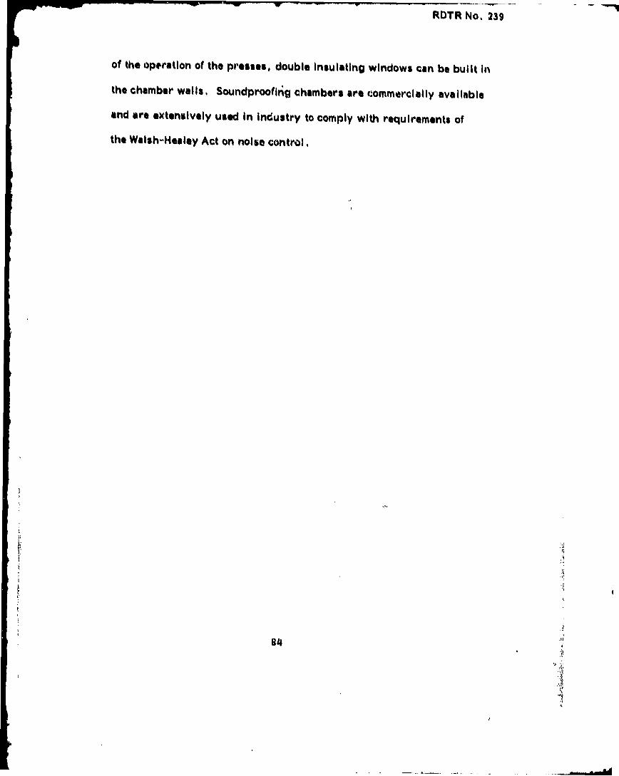
RDTR No, 239
of the operation of the presses, double Insulating windows can be built In
the chamber walls, Soundproofing chambers are commercially available
and are extensively used In Industry to comply with requirements of
the Walsh-Heailey Act on noise control.
84

RDTR No, 239
Work Station: C-5
Assemble Booster Assembly
a. Area of work surface Is not satisfactory as shown in Figure 51. For
four C-5 operators two work tables, each 36 x 72", are needed. Table
height should be 36". This is a seated operation with the most undesirable
seating accommodation: table height is 30" with chair heights of 20", which
is far too much. Seats have no cushioning, no back rests, Dimensions
and seating arrangement for good work table design are discussed earlier
for Work Station: Tray Repair, Recommendations b and c. The work table,
as shown In Figure 40, should be 36" high with a 4"1 high foot rest. The
seat, Figure 41, must be adjustable between 15-18". Knee space of 5"
or more should be provided under the table above the sitting surface.
Good chairs are very Important for good posture control. Proper
support of the back prevents fatigue over extended periods of time spent
in the chair during a normal shift. Chair height and back rest should
be adjustable and be mobile with roller casters, provide swivel motion
in the seat pan, and have sufficient padding in the seat and back rest.
b. Noise level excessively high. If safety permits, considering
the explosive materials being handled in this enclosed area, sound
absorbing panels should be attached to ceiling to reduce noise and
sound reverberations from the smooth wall and ceiling surfaces.
c. A portable restroom is recommended outside the exit. Presently
the workers have to climb and descend a height equivalent to six normal
floors each way to the nearest restroom.
85

RDTR No. 239
p
-1~1
Figure 51. Work Station C-5: Assembling booster units. Work tablesare small, no knee space provided. Chairs should havepadded back rest and sitting surface. Use of foot restsunder table Is recommended.
86

RDTR No. 239
Work Station: C-6
Crimp Booster Assembly
a. The work station should be converted to seated operation. The
reason why the operator stands beside the press, as shown in Figure 52,
is the fact that the supply trays are too far to reach from a seated position.
To accommodate knee space, the table holding the supply trays should be
moved back and a frame constructed for holding the trays above the knees.
Design concept of this work space arrangement is also illustrated in
Figure 52. The seat to be used is shown in Figure 42, it must have padding,
swivel motion, and foot rest. Roller casters are not recommended.
87

RDTR No. 239
~0
00
tC4
F-W
L~
U L2
~c
o0 0
C-M
88.
RDTR No. 239
-APPENDIX
HUMAN FACTORS CHECKLISTOF WORK STATIONS
WORK STATION:
DATE:
HOUR:_
OBSERVER:__
ENVIRONMENT:INSIDE OUTSIDE
A. TEMPERATURE
B. HUMIDITY
C. NOISE
D. ILLUMINATION LEVELS
89

RDTR No. 239
APPENDIX
HUMAN FACTORS CHECKLISTOF WORK STATIONS
WORK STATION: ........ ......
DATE:
HOUR:
OBSERVER:_ _ ___
ENV IRONMENT:I. NSIDE OUTSIDE
A. TEMPERATURE
B. HUMIDITY
S~C. NOISE
-" D. ILLUMINATION LEVELS
89

RDTR No.•39
CHECKLIST FORPERSONNEL WORK SPACE AND ARRANGEMENT
Overall Workplace Layout YES NO N.A.
1. Is the location, size, configuration andaccessibility of equipment such that it isoperable and maintainable by at least the 5ththrough the 95th percentile group of the userpopulation including the full range of clothingwhich they must wear.
2. Adequate space is provided for each operatorin front of the equipment on which he must work.
3. Each operator can leave his workingposition and the compartment without disturbingany other operator.
4. Operators who must communicate directly witheach other verbally are located close to eachother and can see each other's faces at theiroperatitig positions.
,, 5. Aisle space and access aisles to operatingpositions are clear to allow for continuoustraffic where required. __
6. From their operating positions, supervisorscan observe all the personnel under theircharge.
7. Where common displays must be viewed, allof the operators requiring information fromthem have a clear line of sight from theiroperating positions.
8. Emergency equipment is provided in easily
accessible locations and clearly marked.
Equipment Factors -- General
9. The major display for each operatoris mounted perpendicular to his normalline of sight.
10. Other important displays are mountedas close to perpendicular to the operator'snormal line of sight as feasible.
90
-. .. . .~ --- *-... . .. ... . - - . . ,V• I I I I I i " i I i l '

WORK SPACE (Con't) YES NO N.A.
11. Writing space is provided where tasksinvolve the use of books, manuals, orforms.
12. Knee and foot room is provided beneathpanel surfaces. Minimum dimensions are25 inches high, 20 inches wide, and 18inches deep.
13. The height of the writing surfaceabove the floor is 29 inches.
14. Overall equipment height does notexceed 62 inches. If it is desirablefor operator's line of sight to extendbeyond his equipment, overall height doesnot exceed 48 inches.
15. Are controls requiring precise orfrequent operation located between 8 and30 inches above the midpoint of thesitting surface.
16. Visual displays on vertical panelsare mounted in an area no higher than70 inches and no lower than 40 inches
Sabove the standing surface.
17. Precise-reading indicatcv" oimportant controls are pl•-i narea no higher than 64 , • ,lower than 48 inches abs, i.hc n;tdinsurface.
18. Controls mounted on vertical panelsare located in an area no higher than 70inches and no lower than 30 inches abovethe standing surface.
19. Precise controls or controls which areoperated frequently are mounted between 40and 55 inches above the standing surface.
20. Are work benches and work surfaces usedto support jobs, instructions manuals andworksheets provided for standing operatorswith work surfaces approximately 36 inchesabove the floor? _ _
21. Are writing surfaces, if required onequipment consoles, at least 16 inches deep.
91
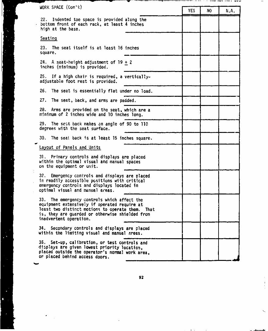
WORK SPACE (Con"O) . -O -YES NO N.A.
22. Indented toe space is provided along thebottom front of each rack, at least 4 incheshigh at the base.
Seating
23. The seat itself is at least 16 inchessquare. . ..-
24. A seat-height adjustment of 19 + 2inches (minimum) is provided.
25. If a high chair is required, a vertically-
adjustable foot rest is provided.
26. The seat is essentially flat under no load.
27. The seat, back, and arms are padded.
28. Arms are provided on the seat, which are aminimum of 2 inches wide and 10 inches long.
29. The seat back makes an angle of 90 to 110degrees with the seat surface.
30. The seat back is at least 15 inches square.
Layout of Panels and Units
31. Primary controls and displays are placedwithin the optimal visual and manual spaceson the equipment or unit.
32. Emergency controls and displays are placedin readily accessible positions with criticalemergency controls and displays located inoptimal visual and manual areas.
33. The emergency controls which affect theequipment extensively if operated require atleast two distinct motions to operate them. Thatis, they are guarded or otherwise shielded frominadvertent operation.
34. Secondary controls and displays are placedwithin the limiting visual and manual areas.
35. Set-up, calibration, or test controls anddisplays are given lowest priority location,placed outside the operator's normal work area,or placed behind access doors. __
92

KK SPACE (Cant) YES NO N.A.
36. When displays are used sequentially, they- are aligned horizontally from left to right as
close to each other as possible.
37. Every control and display on the panel hasa descriptive legend associated with it.
38. The operator's hand does not block the viewof the display when he operates an associatedcontrol.
39. Controls associated with use by the righthand are located below or to the right of theirdisplays, and vice versa for controls operatedby the left hand.
40. There is an adequate separation betweencontrols so that they can be operated easilywithout inadvertent operation of adjacentcontrols.
93

RDTR No, 239
CHECKLIST FOR MATURIAL HANDLING
Handles YES NO N.A.
1. When possible, handles are provided oncovers, drawers and components to facilitatehandling.
2. Recessed rather than extended handle fixturesare provided to conserve storage space or topreclude injury by accidental striking of thehandles.
3. When handles cannot be provided, hoistand lIft points are clearly marked.
4. When possible, handles are located overthe center of gravity to prevent the objectfrom tipping while being lifted or cdrried.
5. Handles are positioned so that they cannotcatch on other units, wiring, protrusions, orstructural members.
6. Handles are placed on any component which,might be difficult to grasp, remove, or carry
or wherever there is a tendency to use fragilecomponents as hand holds.
7. The following dimensions are minimum forhandles to be used by the ungloved hand:
a. Weight to be lifted or moved is under25 Ibs:
Handle diameter; 1/4 - 1/2 inchFinger clear: 2 inchesHandle width: 4 - 1/2 inches
b. Weight to be lifted or moved isover 25 lbs:
Handle diameter: 1/2 - 3/4 inchFinger clear: 2 inchesHandle width: 4 - 1/2 inches
Covers, Cases, and Tool Aids
8. Hinges are used where possible to reducethe number of fasteners required.
94

MATERIAL HANDLINQ (Con't) V. Ls ..
9, When a hinged cover is used, a space equal"to the Dwept volume of the cover is providod(0,0., opening of the cover is not obttrUctedby bulkheads, brackets), ....................
10, Structural me1bers, other components, do notinterfere with removal of a cover,
11, It is evident when the cover is in place butnot secured,
12, Where feasible, guides, tracks, and stopsare provided to facili tate handling and toprevent damage to components,
13, When possible, the same size and type offasteners are used,
14, Where compatible with stress and loadconsiderations, fasteners for mountingcomponents and equipment require at most onecomplete turn,
15. If bolts are required, a minimum numberof turns are required to tighten or loosenthem.
16, Captive nuts and bolts are used wherefeasible,
17. Bolts requiring high torque are providedwith hexagonal heads,
18. Labels are accessible and, where possible,face the operator,
Lifting and Carrying
19, Equipment is modularized such thatweight of removable components is below 20
.pounds whenever possible.
20, Materials or components to be carriedshort distances by one man do not exceed thevalues given in the following table,
Maximum allowable Height liftedweight (lbs) from ground (ft)
142 1139 2
77 355 436 620 6
98
61- AL

MATERIAL HANDLINa (Cont) Y•S NO NCA,
50alle0t allowable openings for one-hand tasks areas follows:
N1, Inserting Qey hand hold flats 21/2 by 4 1/2inches,
22, Salleist square hole through which empty handcan be Insertedt 3 1/4 by 3 1/4 Inches,
0,3 Using 0-inch screwdriver with a 1-inch diameterhandlet 4 by 4 inches,
24, Inserting %mall boxi diameter of the box plus1 3/4 inches.
Smallest allowable opening for two-hand task& are asfollows.
2•B. Reaching through opening with both hands to depthof 6 to 26 inches: width, t th -quatters the depth ofrach; height, 4 Inches.
26. Reaching in to full arm length (to shoulders),straight ahead, with both arms, width, 20 inchesoheight, 4 1/4 Inches.
jimm m
27. Structural members of the chassis do not preventaccess to parts.
28, Units are located so that blind adjustments arenot necessary.
29. Parts frequently aem mounted )n roll-out racks,slides, or hinges.
30. Limit stops are provided on roll-out racks anddrawersV override of these limit stops is easilya(:contpl Ished.
31. Guide pins or their equivalent are provided foralignment.
32. Physically similar but non-interchangeable unitsare so keyed that it is impossible to insert a wrongunit.
33, Components are laid out so that a minimum of,.ýlace-to-place movement by the operator is required.
96 A"41

ROTR No, 139
MATEIUAL HANDLING (Con't) YIE NO N,A.
34, (ompontints Are located and mounted sothat #•co%% to thm may be achieved withoutdanger to Porsollnol (@Igo I ff'osm electricalcharge, heat, sharp edges and points, movingparts, chenmical contamination),
36, Variety of tool) is hold to a minimum,
36, Metal handles are avoided on tools likelyto be used in extreme cold or heat.S- In n il
37. Tools aro of dull finish to avoid glarein strong light, ______ ___________
38, Speed and ratchat-typ. tools areprovided whoen necessary.
39. Non-sparking toolh are provided for useinl an explosive atmosphere.
97

RDTR No. 13s
CHrECKLIST FOR SAFETY YES NO NA,
1, Its the equipment provided with safe handles,lifting rings and/or slings?
2. Is the waight distribution such that theequipment is safe to handlel Mvre, or position? _
3. Is the equipment designed so thAt the centerof gravity and the configuration of logs andsupports makes the equipment unlikely to tipover from unbalance or strong wind?
4, Are handles recessed rather than extendedvwhere they might be hazardous?
6, Are handles positioned so they cannot catchon other units?
6. Have sharp or overhanging edges and cornersthat may cause injury to personnel beenel iminated?
7. Is it evident when a cover is in place butnot secured?
'08, Are struts and latches provided to securehinged and sliding components against accidentalmovement which could cause injury to personnel?
9. Are conspicuous warning placards mountedadjacent to very hot/cold equipment?
10. Do switches or controls which initiatehazardous operations, such as ignition, ovenson, etc., require the prior operation of a relatedor locking control?
11, Are warning plates provided where mechanicalassemblies, linkages, springs, etc. are underconstant strain or load?
12. Are steps and ladders, and methods offastening and supporting them, safe?
13. Do floor surfaces provide adequate non-slipcharacteristics?
14. Can air that is used for equipment cooling becompletely Isolated so as to prevent contaminationif air around personnel?
got1LR:

RDTR No, 239
SAFETY (Con't) YES NO N.A.-- _ _ . . . . .~ m i n' -i
15, Do gears, cams, levers, fans and belts haveadequate safety covers?
16. Where test item design includes the use ofpressurized systems and components are safetyand/or relief valves, controls, and other safetyfeatures provided?
17. Does equipment design include positive stops,torque limiting devices, safety links, fuze plugs,and/or quick release or disconnect features?
18. Are provisions made for protection against eyehazards from flying particles?
19. When gloss is used, is it shatterproof?
20. Are any components mounted such that visionis obstructed?
21. Are potential mechanical hazards adequatelytreated in the draft instruction manual?
22. Are proper tools and test equipment furnishedwith the test item?
23. Are face plates and eye pieces shatterproof?Allow full vision, and cause minimal interferenceto hearing?
24. Do shoes and boots have rigid safety toe?
25. Are sole of boots and shoes slip resistant?
26. Do heavy load items that are man carried haveuick release capability for doffing in emergencyattack, falling, etc.)
27. Is item interface designed so that heavy load
can be lifted with operators back held straight?
28. Are fire and explosion hazards properly safeguarded?
29. Are dangerous fuels, cleaning fluids, acids, caustics,solvents, and other harmful chemicals properly marked,stored and handled?
30. Are portable, hand-operated fire extinguishers providedwhere fire hazards exist or may be created, and are theyif the correct type?
99
L. .... ' d * I I i iI - -

SAFETY (Con't) YES NO N.A.
31, Are fire extinguishers placed wnere thfy"are readily accessible, but not immediatelyadjacent to points where fire would probablyoriginate? .
32, Are suitable safeguards provided fordetection and elimination of toxic dusts,gases, fumes, and mists? -m---.. .. _ '_
33, Are appropriate measures taken to protectpersonnel from visible and invisible highintensity light sources? -
34, Are properly marked, positioned, andunobstructeu fire exits provided?
35, Are all requirements for protective ,clothing explicitly noted? ...
36. Are all safety limitations in equipmentusage clearly defined?
37, Are warning signs coded and colored?
100

RDTR No. 239
CHECKLIST FORPHYSICAL ENVIRONMENT OF PERSONNEL
Lighting. YES NO
1, Adequate general illumination is suppliedfor movement of personnel without visualhindrance,
2, Adequate illumination levels are providedon all work surfaces and panels wherespecific requirements for low level illuminationare not present.
3. Local light units are provided for exactingvisual tasks where required, or where generalillumination is inadequate.
4. Luminaires and reflecting surfaces (likescope faces and meter cover glasses) are soarranged in relation to each other that noglare is present at the eye of the operatorn his normal operating position.
5. Work surfaces and panel faces have a non-glare finish.
6. Panels have illumination of adequateuniformity. There should be no significantlight and dark areas.
Air Conditioning
7. Temperature is controllable within therange of 65 to 80OF to + 20 under ambienttemperature conditions.- (This range shouldbe lower for operation requiring a greatamount of activity by operators).
8. No large surface has a surface temperaturegreater than lO°F different from the controlledair temp rature.
9. Air movement Is no noticeable or disturbingin the vicinity of working positions.
10. Humidity is controlled between 30 and 70%.
11. Provision is made to control noxiousfumes and gases, dusts and odors belowperceptible levels, or below levels which are
-likely to produce some undesirable physiologicaleffects.
101

RDTR No. 239
PHYSICAL ENVIRONMENT (Cont) YES NO N.A.
12. An adequate volume per unit time ofclean air is provided.
Noise and Vibration
13. Vibration is controlled so thatpersonnel task accomplishment isnot interfered with. ___.. __.__
14. Maximum integrated noise level.
15. Where frequent conversation isrequired between operators, maximumintegrated noise level is no more than70 db.
16, Where exposure to high noise levelsis required, operators are supplied withand required to wear ear protection.
102
AM

CHECKLIST FOR DISPLAYS
Information and Signals YES NO N.A.
1. Information presented is necessary forthe decisions or actions required of theoperator.
2. Information is presented in the mostimmediately meaningful form (i.e., nointerpretation or decoding is required).
3. Information is displayed to the accuracyrequired by the decisions or actions of theoperator, and preferably no more accuratelythan required.
4. If scale interpolation is required, itdoes not introduce a probability foroperator errors which are greater than theoperator's task permits.
5. Information for different types ofactivities.
6. Failure in the unit is clearly shownor the operator is otherwise warned.
7. Visual signals are of sufficient size,brightness, and duration to be easilyand obviously seen.
8. Duration of visual signal is neverless than 0.5 second and, where applicable,the signal lasts until the appropriateresponse has been made.
9. When a task is extended in time, a flashingsignal is used (rather than a steady one)because of its greater attention-getting value.
10. Important signals are placed directly infront of the operator or as close to thisposition as possible.
11. For flashing signals, the flash rateshould be high (at least one cycle persecond with the "on" period at 0.5 second).
103
7"

RDTR No. 239
DISPLAYS (Can't) YES NO N.A.
12. Auditory signals are sufficiently -
different from the prevailing noisebackground to be easily and obviouslyheard.
13. Auditory signal duration is atleast 0.5 second and, where applicable,the signal lasts until the appropriateresponse has been made.
General Design
14. The display can be read easilyfrom the expected or normal locationsof all operators who require theinformation.
15. Company trade names or othermarkings irrelevant to the display(e.g., patent numbers) do not appearon the display in a manner that isdistracting..-.-
16. When the operator must monitor and/or perform a sequence of operations, thedisplays are arranged in the actualorder of events.
17. When no definite sequence ofoperations determines the order ofevents, the displays are grouped byfunction. ..... .
18. The relationship between the displayand its associated controls is un-mistakable in terms of:
a. The proper control to use.
b. The direction of movement ofthe control.
c. The rate and limits of movementof the control.
19. The display is designed to minimizethe problem of parallax within the normalq visual axis of the operator.
104

RDTR No. 239
"DISPLAYS (Con't) NOYES NO N.A.
20. Are emervency controis and displays placed inreadily accessible positions within 30 degrees ofthe operator's normal line of sight?
21. Are emergency controls and displays locatedin the optimum areas in preference to primarycontrols and displays, when the nature of anemergency is so critical that emergency controlsand displays should be given top priority inlocation?
22. Are secondary controls and displays (lessimportant than primary ones but usedperiodically during normal operations) placedwithin the optimum areas? Is their exactlocation determined primarily by associationand proper grouping?
Illumination
23. Contrast between pointers, markings, andcharacters and the background under allexpected conditions of illumination isadequate for ready reading.
S24. If the instrument has a movablepointer, the pointer is well illuminated atall positions.
25. Brightness is uniform over the displayface.
26. Glare does not interfere with theinterpretation of the display regardless ofthe display location in the work area.
Coding
27. Zone markings are employed as necessaryto indicate the various zones of operatingconditions (e.g., desirable operating range,danger-lower limit, danger-upper limit,caution, undesirable-inefficient).
28. Color coding is generally as follows:red requires immediate action, yellow, cautionand monitor green, proceed normally; white,combine information to determine requiredaction; blue, command to take action.
105

DISPLAYS (Con't) YES NO N.A.
29. Indicator lights used for the most criticalconditions are significantly different fromthe other indicator lights (i.e., in color,brightness, or size).
Legends
30. All letters are capitalized except forextended copy which is in capitals andlower case letters.
31. All numbers are Arabic except for specialidentification.
32. The use and symbols is avoided, but, ifsymbols are used, they are common meaningfulones.
33. Letters, numbers or other symbols are aminimum of 1/8 inch high.
34. Indicators are labeled according tofunction.
35. Legends are uniform and standardizedv for ease of recognition (i.e., when
indicators serving the same function appearin different places, all are labeled inthe same manner).
36. Legends are brief, but no so briefas to be ambiguous. _
37. If abbreviations are used, they con-form to common usage.
38. Legends are permanently affixed byeither etching or embossing, or, ifsurface legends must be used, decalswith a protective coating or embossedmetal identification "metalcals" areused. - -
39. Legends are not obscured by parts,components, moisture proofing covers.
40. The legend is placed on, or sufficientlyclose to, the display (preferably abovethe display) which it identifies so thatthere is no ambiguity concerning the
• relationship.
106

RDTR No. 239DISPLAYS (Con't)
YIES BO NA41. Legends consist of black characters YE .on a light background, except forblack-lighted panels where illuminatedcharacters on a dark background areused.
Dials, Gauges, and Meters
42. Changes in indication are easy todetect both in magnitude and direction.
43. The relationship between a dial andother dials in its associated panelgrouping is similar in terms of:
a. Scale breakdown and numericalprogression.
b. Values on all dials increase inthe same direction.
c. Under normal operating conditions,all pointers are in the samerelative position.
44. The scale numbers increase in aregular and obvious sequence.
45. The scale graduation interval(distance between graduation marks)is approximately equal to the degreeof accuracy required in reading theindicator.
46. All major scale divisions arenumbered.
47. The pointer extends to, but does notcover, scale graduation marks.
48. If possible, numerals appear on theopposite side of the graduation marks fromthe pointer so that the pointer does notcover them in reading.
49. The dial face is designed as simplyas possible and only infornation which isusable by the operator appars on thedisplay (i.e., manufacturerW name, doesnot appear).
107
f4A. . . .4 ,I ~ l..

tKU IK NU 44V
DISPLAYS (con't) --.-- .-
YES NO NA,50. The circular scale numbers increase ina clockwise direction (i.e., clockwiepointer movement indicates an increase inmagnitude).
51. The pointer moves cloo.kwise as aresult of moving an associated lever onswitch clockwise, upward, forward, or tothe right.
52. The circular scale zero is locatednear the bottom of the dial except whenzero calibration or check reading isrequired.
53. Except on multirevolution instruments,there is a scale break of at least 1-1/2major divisions at the end of the scale.
54. Numerals arranged so that they areupright in all positions.
1 08
-- • ... ..... .. , , , , , i 1 I" • 1 t i• I l I I I '1 I I .. .i

n o w 9U ' a S
CIHCKLIST FOR CONTROLS- -
S 1)NO N,^,
I. The control require# at few mov•montsas possible,
2, Succe~sive control movements are inter-related (ie, one move•nt p44se40 eIllyinto the neot.-
3. Controls uaed in rapid sequence haveuniform direction of motion,
4, Conter1 movements are consistent forall equipments which one operator uses,
5, Are discrete-adjustment type (detent)controls used when perforince requirementsare suLh that the controlled object can beadjusted in a limited number of discretesteps? __. ...__,,__
6. Are continuous adjustment type controlsused when precise adjustinents are neededalong a continuum, or when a large numberof settings (usually more than 24) isrequi red? __ __,
7. Are controls oriented to fit normalhabit-pattern reflexesi e, g., does aclockwise movement of the control producea clockwise motion to its visual display?
8. Are controls shape curded, where possible,to improve visual And tactile identification,by the use of standardized shapes and, whenfeasible, functional shapes which suggest thepurpose of the controls?
9. Control movement to produce any increasein magnitude, including switching "on" is asfollows: I
a. For linear controls: movement forward(i.e., away from the operator), upwardor to the right; and for overheadlinear controls: movement to the right.
109

CONI'tO05 (CO010 0) ..-......to et._ L_ _ N.A.
1),~~~m Fora rm m 01roi oon
10, The control It pityti•caIly doeiunedto stand Autos, ovion %unexpecteddtfl1etion of ovement 00, , energy oDlnic resoponti),
11, POQitiv@ indication il providedthat the activation of a contpul hasrosqlted in equipment rtiponsi,
kmm - -
IP, If th" operator's talks are Qotpl)O,the controlo Are distributed so thatIto one limb is overbumiened,
13, Controla requirinO raid, precisesettings Are assigned L t e hands,
14, Controls requiring la0g4 Amounts of mmicontinuous forward application of forceare assigned to the feet,
' 16. Similar controls Are grouped.
16, Rele'.aonship between the cTOl-tro-and other contro s in its associatedpanel group arrangement is unmistakablei A terms oft
a. All controls progress in thesame direction,
b. All control pointers are in thesame relative position under normaloperating conditions.
c. Associated controls are groupedand additionally related by markedoutlines if necessary.
17, All pr- -ry and emergency controlsare easily ilentiftable both visuallyand non-visually,
110

"RrTR No, I•1
CONTROLS (Con't) - -A-
10, Qualitative ode ar@ used to codequalitative information (ie,, geometricshape s or Color%),
IQ, QuantitatIve codes are used tocode quantitative information (iseC,04i41 brightnous, leng th),
20, The most important and mostfrequently used controls art locatedin front of the operator in the
optimum lmnual areas as follows=
a, Located within comfortablereach, or
b, Between elbow and shoulderheight for hand controls,
-- - -,, | I
C, Emergency controls arequickly identifted andlocated for maximum speedof operation, ....
21, Are warning lights an integralrt oft or located adjacent to, the
rover switch, or other control deviceby which the operator is to take action?
Shape, Cding-
22. Shapes can be discerned bothvisually and 'tactually.
23, If the coded control presents sharpedges, a clean grasp area is provided.
Size Coding
24. If.the operator cannot comparethe sizes of all controls beforeselecting the proper one, only twoor three different sized controlsare used in any one group.
___-, -i
25. Controls of the same size areused for performing similar functions.
111
...
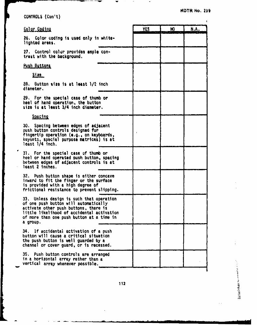
MtYTR No, 239CONTROLS (Con' t)
2;,. Color coding is used only in white-lighted are#*,
27, Control color provides ample con-trast with the background,Push tIuttoni - -
28. iButton size is at least 1/t inchdiameter,
29, For the special case of thumb orheel of hand operation, the buttonsize is at least 3/4 inch diameter.
SRACJI n-
30. Spacing between edges of adjacentpush button controls designed forfingertip operation (e.g., on keyboards,keysets, special purpose matrices) is atleast 1/4 inch.
• • II "'- . l ---
31. For the special case of thumb orheel or hand operated push button, spacingbetween edges of adjacent controls is atleast 2 inches,
32, Push button shape is either concaveinward to fit the finger or the surfaceis provided with a high degree offrictional resistance to prevent slipping.
33. Unless design is such that operationof one push button will automaticallyactivate other push buttons, there islittle likelihood of accidental activationof more than one push button at a time ina group.
34. If accidental activation of a pushbutton will cause a critical situationthe push button is well guarded by achannel or cover guard, or is recessed.
35. Push button controls are arrangedin a horizontal array rather than avertical array whenever possible.___
112
W

KUTR No, 239
CONTROLS (Con't) YES NO- N.A,
36•, Spacing between adjacent edges of toggle -levers mounted in a row is at least 3/4 inch.
37, Th• displacement of toggle lever issufficient for visuAl and tactual discriminationin its particular application,
38, For two-position switch, centerlinedisplacement betwoen on-off mode is at least60 degrees,
39, For three-position switch, centerlinedisplacement between adjacent positions isat, least 40 degrees from center,
40. If mounted horizontally, it is so onlyto be consistent with orientation of thecontrolled function and movement forwardor to the right corresponds to "on", or"increase", while motion rearward or to theleft corresponds to "off", "stop", or"decrease".
41. Rows of toggle switches are mountedin a horizontal (rather than vertical)array to prevent inadvertent activationof the wrong switch.
42. Critical toggle switches are pro-vided with a locking device or controlguard cover so that at least two discrete'operator movements are required to activatethe control.
Rotary_ Selector Switches
Size
43. For circular control, the knob diameteris from I to 4 inches.
44. Pointer or knob grasp depth is at least1/2 inch (but not more than 3 inches).
45. Displacement between adjacent detents isat least 15 degrees or 1/4 inch, whichever isgreater (i.e., for 15-degree displacement.index marks are arranged on at least a 1 3/4inch diameter).
113

RQTR No. 239CONTROLS (Con't) -
YES NO NA,46. Maximum displacement between detents is -
45 degrees except where contrast size orpower requirements necessitate widerspacing, in which case up to 90 degrees isacceptable.
General
47. The selector switch has a fixed scalewith a moving pointer.
48. The knob pointer is close to the scaleindex mark to minimize parallax.
49, All knobs are black except in red-lighted areas where all knobs are gray.
50. Pointer and index marks and charactershave sufficient contrast with their back-grounds to be readily visible under allexpected conditions of illumination.
51. Where several knobs of similarappearance are grouped, controldiscriminability is optimized byincreased physical separation, controlcoding, or the insertion of dissimilarcontrols between them.
52. The grasp area on the control knobis provided with a rough surface finishto prevent slipping.
53. Detents are provided at each controlsetting.
54. Where a selector switch has more than4 positions and multiturn operation is notrequired, start and end stops are provided(i.e., two positions in addition to thenumber of active mode settings).
Knobs
55. For fingertip grasp, knob dimensionsare as follows:
a. Knob diameter is minimum 3/8inch, Wiimum 4 inches.
114
Ilia -. . . ... . • . iI m • - I ° i I I• • r'- I I ':' • - I I , I j

CONTROLS (Con't) RDTR No- 239
YES NO N.A,b. Knob depth or grasp area is minimum
1/2 inch maximum 1 inch.
56, For palm grasp (or door knob type knob)dimensions are as follows: knob diameter isminimum 1 1/2 inches, maximum 3 inches.
57. If a pointer or index mark is used onthe continuous control, it is close to thescale index mark to minimize parallax.
58. Index numbers are not obscured when handis on the control knob.
59. All knobs are black, except in red-lighted areas where all knobs are gray.
60. Pointer and index marks and charactershave sufficient contrast with their back-grounds to be readily visible under allexpected conditions of illumination.
61. The grasp area on the control knobis provided with a rough surface finish toprevent slipping (knobs over 1 inch diameterare serrated).
Cranks
62. Crank radius for light load and highrate (up to 275 rpm) is not optimum consistentwith performance requirements and within thefollowiny recommended radius values: minimum1/2 inch, maximum 4 1/2 inches.
63. Crank radius for heavy loads is optimumconsistent with performance requirements asfollows:
a. For under 175 rpn rate and heavy loadradius is within the followingrecommended values: minimum 5 inches,maximum 8 inches.
b. For extra heavy loads, maximum radiusis 20 inches.
64. Spacing between the outside edge of thecrank handle and any other obstruction is atleast 3 inches. _ _
115/•

RDTR No. 239
CONTROLS (Con't) YESNONE:
65. The crank is used for tasks requiring atleast two rotations of control movement.
66. For tasks involving large slewing movementsplus small fine adjustments (less than 1/2rotation) the crank is mounted on a knob.
Handwheels
67. Cross-sectional diameter of handwheel rimis at least J/4 inch but not greater than 2inches.
68. Indentations are built into the rim toaid in holding it.
69. Handwheel is located so that there isat least 3 inches between the outer edge andthe nearest obstruction.
Levers (Under 6 Inches)
70. Fcr fingertip grasp, knob diameter isbetween 1/2 inch and I inch.
71. The lever does not protrude from thepanel surface more than 6 inches.
72. For one hand, random operation of a lever,at least 2 inches separation between the outeredge of the lever at maximum displacement andany obstruction is maintained.
73. For two hands, simultaneously operatingadjacent levers, at least 3 inchesseparation is maintained.
74. For discrete position lever controls,either a locking slot or a detent is providedat each control position.
75. Operator performance is not hampered byexcessive control resistance.
76. Support is provided for the body partbeing used in making fine adjustments withsmall lever type controls as follows:
116

. YES NO N.A.a. For finger movements, the wrist is
supported.
b. For small hand movements, the fore-arm is supported.
c. For large hand movements, the elbowis supported.
Foot Controls
77. For foot activated push button, theeffective button diameter is at least1/2 inch.
78. For control using a pedal, pedalsize is at least 1 by 4 inches.
79. For operator expected to wear normalor light footwear, displacement is atleast 1/4 inch.
80. For operator expected to wear heavyfootwear, displacement is at least Iinch.
81. For control operated by ankle flexingonly, maximum displacement is 2 1/2inches.
82. For control operated by leg movement,maximum displacement is 4 inches forpush button and 7 inches for pedal.
83. When foot does not rest on the con-trol, resistance is at least 4 pounds.
84. When foot may rest on the control,resistance is at least 10 pounds.
85. For normal operation with footresting or not resting on control,maximum resistance is under 20pounds.
86. Foot push button or pedal will re-turn to the null position when forceis removed. _
117

WOOF.. .
RDTR No. 239i
REFERENCES
1. Grandjean, E: Fitting the Task to the Man, Taylor and Francis, London,1969.
2. Military Standard Human Factors Engineering Design Criteria forMilitary Systems, Equipment and Facilities, MIL-STD-1472A, 15 May 1970.
3. Murreli, K.F.H: Ergonomics, Man in His Working Environment, Chapmanand Hall, London, 1969.
4. U. S. Army HEL Standard S-3-65, Human Factors Engineering DesignStandard for Missile Systems and Related Equipment, September, 1965.
5. U. S. Army HEL Standard S-6-66, Human Factors Engineering DesignStandard for Wheeled Vehicles, September 1966.
6. U. S. Army Test and Evaluation Command, Common Engineering TestProcedure, Human Factors Engineering, Material Test ProcedureG-2-502, 27 August 1969, AD 720976.
7. U. S. Army Test and Evaluation Command, Common Service TestP. cedure, Safety Material Test Procedure 10-3-507, 7 December 1970,AD 879051
8. U. S. Army Test and Evaluation Command, Common Service TestProcedure, Human Factors, U. S. Army Airborne, Electronics andSpecial Warfare Board, Material Test Procedure 6-3-525, I July 1971,AD728824.
9. VanCott, H. P. and R. G. Kinkade: Human Engineering Guide toEquipment Design. US Government Printing Office, Washington,D. C., 1972.
10. Woods, W. E. and Conover, D. W.: Human Engineering Guide for EquipmentDesigners, University of California Press, 1970.
1118