Distillation Column Design
24
DESIGN OF A PACKED DISTILLATION COLUMN NAME : Sandaruwan R.A.N. INDEX NO : 090466M DATE OF SUB: 01 / 08 / 2013
-
Upload
sihanu-subasingha -
Category
Documents
-
view
221 -
download
10
description
packbed distillation column design
Transcript of Distillation Column Design

DESIGN OF A PACKED DISTILLATION
COLUMN
NAME : Sandaruwan R.A.N.
INDEX NO : 090466M
DATE OF SUB: 01 / 08 / 2013

Task identification
According to the determination of packed column height through the number of ideal stages and the
HETP value, first the conditions and the objective of the column have to be clarrified using the data
provided by the customer. So the required data has been provided as follows.
System: carbon disulphide – carbon tetrachloride
Feed rate: 45kmol/hr Feed condition: saturated liquid
Feed composition: 40mol% carbon disulphide
Distillate composition: 90mol% carbon disulphide
Bottom product composition: 4mol% carbon disulphide

Selection of packing material
Principal requirements of a packing are,
Provide a large surface area for high interfacial area between the gas and liquid
Have an open structure, so low resistance to gas flow
Promote uniform liquid distribution on the packing surface
Promote uniform vapour gas flow across the column cross section
To satisfy these requirements many diverse types and shapes have been developed.
In this distillation column design, berl saddles types rings are used as packing material. Berl
saddles were developed to give improved liquid distribution compared to rasching rings. These are the
original type of saddle packing. They have a smaller free gas space but their aerodynamic shape is
better giving a lower pressure drop and higher capacity. They are usually made up by ceramic or metal
or carbon or plastic. The choice of material will depend on the nature of the fluids and the operating
temperature. Ceramic packing will be the first choice for corrosive liquids and low cost. Metal packing
are usually selected for non corrosive service. They have higher capacity and efficiency. Plastic are
normally polypropylene. It is inexpensive and most popular when temperature does not exceed 250˚F.
In the process industries, random packings re more commonly used.
So for this design plastic berl saddles are selected and random packing is used.
Packing size
In general the largest size of packing should be used upto 50mm. small sizes are more
expensive than the larger sizes. The size of packing used influences the height and diameter of a
column, the pressure drop and cost of packing. When packing size is increased, the cost per unit
volume of packing and the pressure drop per unit height of packing are reduced, but in other side
which will reduce the mass transfer efficiency. Reduced mass transfer efficiency results in a taller
column. Also use of too large a size in a smaller column can cause poor liquid distribution.
In this design packing size is selected as 25mm to maintain the column diameter below 0.3m.
Pressure drop across packing
Recommended design values, mm water per m packing
According to this, 60mm water per m of packing is selected as pressure drop.

Calculating equilibrium data
Equilibrium data calculation for Carbon disulphide – Carbon tetrachloride vapour – Liquid system
According to antion equation
𝑙𝑛 𝑃˚ = 𝐴 − 𝐵/(𝑇 + 𝐶)
Where, A, B, C - Constants in the antion equation
Vp - Vapour pressure (mmHg)
T - Temperature (K)
Antion constants for Chloroform and Benzene
Carbon disulphide (A) Carbon tetrachloride (B)
A 15.9844 15.8742
B 2690.85 2808.19
C -31.62 -45.99
Boling point of Carbon disulphide = 46˚C
Boling point of Carbon tetrachloride =77˚C
From Raoul’s law,
P = Pox Where, P - Partial pressure
Po – Vapour pressure
X – Molar fraction in the liquid phase
Applying Raoult’s law for A and B;
PA = P0
AxA
PB = PoBxB
From Daltons Law;
pA + pB = PT
Where, PT – Total pressure
pA + pB = PT = pO
AxA + poBxB
PT = 750 mm Hg (1bar)
xA + xB = 1
pA + pB = PT = p0
AxA + poB (1 - xA)
PT - p0
B
xA = ----------
p0
A - poB
From Dalton’s law;
PA = yAPT

yA = (pO
A/PT) xA
Sample calculation
At 46 ˚C
𝑙𝑛 𝑃˚𝐴 = 𝐴 − 𝐵/(𝑇 + 𝐶)
= 15.9844-2690.85/(319-31.62)
𝑙𝑛 𝑃˚𝐴 = 6.621
𝑃˚𝐴 = 750.695Hgmm
𝑙𝑛 𝑃˚𝐵 = 𝐴 − 𝐵/(𝑇 + 𝐶)
=15.8742-28.08.19/(319-45.99)
𝑙𝑛 𝑃˚𝐵 = 5.588
𝑃˚𝐵 =267.2Hgmm
PT - p0
B
xA = ---------- yA = (pOA/PT) xA
p0
A - poB
=0.999 = 0.998
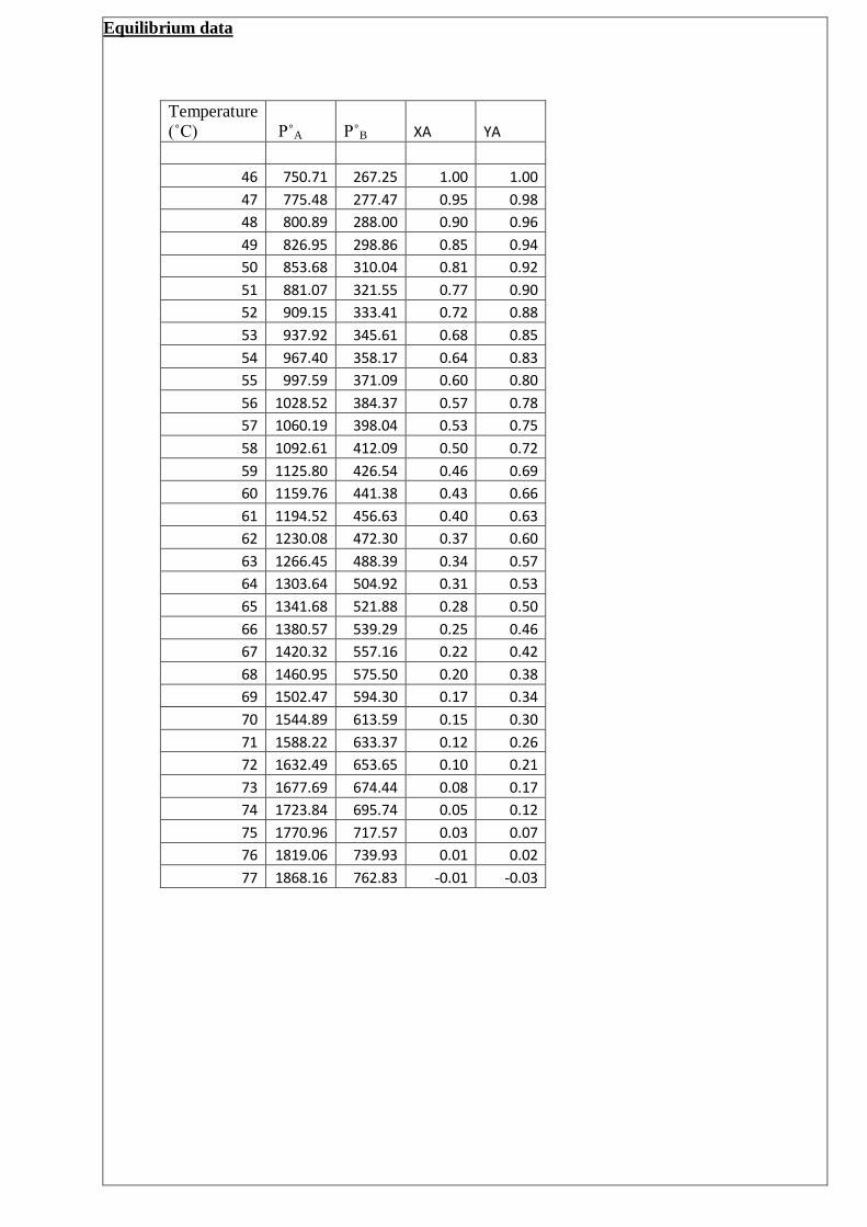
Equilibrium data
Temperature
(˚C) P˚A P˚B XA YA
46 750.71 267.25 1.00 1.00
47 775.48 277.47 0.95 0.98
48 800.89 288.00 0.90 0.96
49 826.95 298.86 0.85 0.94
50 853.68 310.04 0.81 0.92
51 881.07 321.55 0.77 0.90
52 909.15 333.41 0.72 0.88
53 937.92 345.61 0.68 0.85
54 967.40 358.17 0.64 0.83
55 997.59 371.09 0.60 0.80
56 1028.52 384.37 0.57 0.78
57 1060.19 398.04 0.53 0.75
58 1092.61 412.09 0.50 0.72
59 1125.80 426.54 0.46 0.69
60 1159.76 441.38 0.43 0.66
61 1194.52 456.63 0.40 0.63
62 1230.08 472.30 0.37 0.60
63 1266.45 488.39 0.34 0.57
64 1303.64 504.92 0.31 0.53
65 1341.68 521.88 0.28 0.50
66 1380.57 539.29 0.25 0.46
67 1420.32 557.16 0.22 0.42
68 1460.95 575.50 0.20 0.38
69 1502.47 594.30 0.17 0.34
70 1544.89 613.59 0.15 0.30
71 1588.22 633.37 0.12 0.26
72 1632.49 653.65 0.10 0.21
73 1677.69 674.44 0.08 0.17
74 1723.84 695.74 0.05 0.12
75 1770.96 717.57 0.03 0.07
76 1819.06 739.93 0.01 0.02
77 1868.16 762.83 -0.01 -0.03
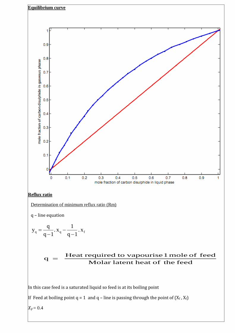
Equilibrium curve
Reflux ratio
Determination of minimum reflux ratio (Rm)
q – line equation
In this case feed is a saturated liquid so feed is at its boiling point
If Feed at boiling point q = 1 and q – line is passing through the point of (Xf , Xf)
𝑋𝐹= 0.4
fqq x. 1q
1 x.
1q
qy
feed theofheat latent Molar
feed of mole 1 vapourise torequiredHeat q

Top operating line equation
Dn1n .x
R1
1.x
R1
Ry
But, at minimum reflux ratio we can rewrite top operating line equation as follows,
Dn1n .xRm1
1.x
Rm1
Rmy
Top operating line is passing through the point of (XD , XD)
XD = 0.9
In minimum reflux ratio intersection of the top operating line and Q line should be at the curve.
According to the graph,
Intercept of the top operating line = 0.414
Gradient of the top operating line = 0.54

Therefore Rm1
Rm
= 0.54
Minimum reflux ratio, Rm = 1.174
Operating reflux ratio
When we operate high reflux ratio our plates are less than high reflux ratio. Then construction
cost is less. But we have to spend lot of money on operating cost and steams. So in industry reflux
ratio is between 1.2-1.5 of minimum reflux ratio. Here distill concentration is high so I think operating
reflux ratio should be 1.3Rm
R = 1.3Rm
Then operating reflux ratio = 1.3 * 1.174
R = 1.5262
HETP Value
For the design of packed distillation columns it is simpler to treat the separation as a stage
process and use the concept of the height of an equivalent equilibrium stage to convert the number of
ideal stage required to a height of packing.
The height of an equivalent equilibrium stage, called height of a theoretical plate (HETP), is the height
of packing that will give the same separation as an equilibrium stage. The HETP for a given type and
size of packing is essentially constant and independent of the system physical properties.
HETP value for a packing size of 25 mm can be assumed as a 0.46 m.
Number of ideal stages required
Then top operating line equation,
𝑦𝑛+1= 0.6041 𝑥𝑛 + 0.3563
q = 0.4

No of ideal stage required = 12-1
= 11
Feed tray location is above the 5th
tray from the top of the tower
Column height
Column height = number of stages * HETP
= 11* 0.46 m
= 5.06 m
Column height = 5.1m

Column diameter
Material balance
F = D + W
Material balance for carbon disulphide
F.𝑥𝑓 = D𝑥𝑑 + W𝑥𝑤
F.𝑥𝑓 = D𝑥𝑑 + (F-D)𝑥𝑤
D = 𝐹(𝑥𝑓−𝑥𝑤 )
𝑥𝑑−𝑥𝑤
D = 45(0.4−0.04)
0.9−0.04 kmol/hr
D = 18.837 kmol/hr
Then,
W = (45 – 18.837)kmol/hr
= 26.163 kmol/hr
Material balance for rectifying section
L + D = G
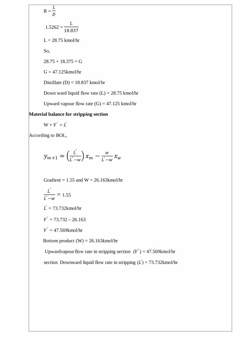
R = 𝐿
𝐷
1.5262 = 𝐿
18.837
L = 28.75 kmol/hr
So,
28.75 + 18.375 = G
G = 47.125kmol/hr
Distillate (D) = 18.837 kmol/hr
Down ward liquid flow rate (L) = 28.75 kmol/hr
Upward vapour flow rate (G) = 47.125 kmol/hr
Material balance for stripping section
W + 𝑉 ′ = 𝐿′
According to BOL,
𝑦𝑚+1 = 𝐿′
𝐿′−𝑤 𝑥𝑚 −
𝑤
𝐿′−𝑤𝑥𝑤
Gradient = 1.55 and W = 26.163kmol/hr
𝐿′
𝐿′−𝑤 = 1.55
𝐿′ = 73.732kmol/hr
𝑉 ′ = 73.732 – 26.163
𝑉 ′ = 47.569kmol/hr
Bottom product (W) = 26.163kmol/hr
Upward vapour flow rate in stripping section (𝑉 ′ ) = 47.569kmol/hr
Downward liquid flow rate in stripping section (𝐿′) = 73.732kmol/hr

Vapour liquid equilibrium mixture for carbon disulphide and carbon tetrachloride
For rectifying section
Composition of the 4th
tray (above plate to the feed)
𝑦5= 0.62
𝑥4 = 0.43
So, temperature of the 4th tray = 333K
Composition of the 1st tray (top plate to the feed)
𝑦1 = 0.9
𝑥0 = 0.9
Temperature of the 1st tray = 324K
Average temperature of the striping section = 333+324
2 K
= 328.5K
Average carbon disulphide composition of vapour (y) = 0.760
Average carbon disulphide composition of liquid (x) = 0.665

Density
Molecular weight of C𝑆2= 0.0761kg/mol
Molecular weight of C𝐶𝑙4= 0.1538kg/mol
For rectifying section,
Density of C𝑆2 at 328.5K = 1207.566kg/𝑚3
Density of C𝐶𝑙4 at 328.5K = 1526.596 kg/𝑚3
For liquid
Weight fraction of C𝑆2= 0.665×0.0761
0.665×0.0761+0.335×0.1538
= 0.4955
Basis 1000kg,
Volume of C𝑆2=0.4955×1000
1207.566
= 0.41𝑚3
Volume of C𝐶𝑙4= 0.5045×1000
1526.596
= 0.33𝑚3
Density of liquid mixture = 1000
0.41+0.33
= 1351.35kg/𝑚3
For vapour mixer
According to, PV = nRT
ρ = 𝑃𝑀
𝑅𝑇
Average molecular weight of the vapour stream = 0.76×0.0761+0.24×0.1538
= 0.09475kg/mol

ρ = 1×105×94.75
8.314×328.5
Density of vapour mixture = 3.47kg/𝑚3
For stripping section
Composition of 6th
plate (below plate to the feed tray)
𝑦6= 0.58
𝑥5 = 0.38
Temperature of the 5th tray = 334 K
Composition of 11th
plate (lowest plate of tower)
𝑦12 = 0.07
𝑥11 = 0.06
Temperature of the 11th plate = 347 K
Average temperature for stripping section = 334+347
2
= 340.5 K
Average carbon disulphide composition of vapour (y) = 0.325
Average carbon disulphide composition of liquid (x) = 0.22
Density of C𝑆2 at 340.5K = 1187.885 kg/𝑚3
Density of C𝐶𝑙4 at 340.5K = 1503.208kg/𝑚3
Similar to above calculation,
For liquid mixer
Weight fraction of the C𝑆2 = 0.1225
Density of liquid mixture = 1455.8kg/𝑚3
For vapour mixer
Average molecular weight of the mixer = 0.12855kg/mol
Density of vapour mixer = 4.541kg/𝑚3

Column diameter for rectifying section
Gas flow rate = 47.125 kmol/hr = 47.125×0.09475×103
3600 kg/s
= 1.24 kg/s
Average molecular weight of liquid mixer = 0.665×0.0761+ 0.335×0.1538
= 0.1021kg/mol
Liquid flow rate = 28.75kmol/hr = 28.75×0.1021×103
3600kg/s
= 0.8154kg/s
Gas density at 328.5K = 3.47kg/𝑚3
Liquid density at 328.5K = 1351.35kg/𝑚3
𝐹𝐿𝑉= 𝐿𝑤
𝑉𝑤
ρ𝑣
ρ𝐿
= 0.8154
1.24
3.47
1351.35
= 0.033
Pressure drop correlation graph
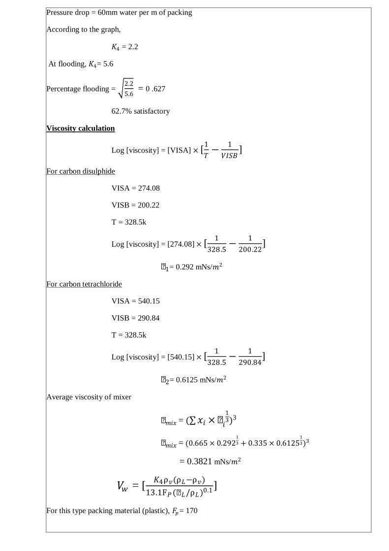
Pressure drop = 60mm water per m of packing
According to the graph,
𝐾4 = 2.2
At flooding, 𝐾4= 5.6
Percentage flooding = 2.2
5.6 = 0 .627
62.7% satisfactory
Viscosity calculation
Log [viscosity] = [VISA] × [1
𝑇−
1
𝑉𝐼𝑆𝐵]
For carbon disulphide
VISA = 274.08
VISB = 200.22
T = 328.5k
Log [viscosity] = [274.08] × [1
328.5−
1
200.22]
µ1= 0.292 mNs/𝑚2
For carbon tetrachloride
VISA = 540.15
VISB = 290.84
T = 328.5k
Log [viscosity] = [540.15] × [1
328.5−
1
290.84]
µ2= 0.6125 mNs/𝑚2
Average viscosity of mixer
µ𝑚𝑖𝑥 = ( 𝑥𝑖 × µ𝑖
13)3
µ𝑚𝑖𝑥 = (0.665 × 0.2921
3 + 0.335 × 0.61251
3)3
= 0.3821 mNs/𝑚2
𝑉𝑤 = [𝐾4ρ𝑣(ρ𝐿−ρ𝑣)
13.1F𝑃(µ𝐿/ρ𝐿)0.1]
For this type packing material (plastic), 𝐹𝑝= 170

𝑉𝑤 = [2.2×3.47(1351.35−3.47)
13.1×170(0.3821/1351.35)0.1]
= 10.46kg/𝑚2𝑠
Column area required = 1.24
10.46 = 0.1185𝑚2
Diameter = 4
𝜋× 0.1185
Diameter of the rectifying section= 0.388m
Column diameter for stripping section
Gas flow rate = 47.569kmol/hr = 47.569×0.12855×103
3600 kg/s
= 1.7 kg/s
Average molecular weight of liquid mixer = 0.22×0.0761+ 0.78×0.1538
= 0.1367kg/mol
Liquid flow rate = 73.732kmol/hr = 73.732×0.1367×103
3600kg/s
= 2.8kg/s
Gas density at 340.5K = 4.541kg/𝑚3
Liquid density at 340.5K = 1455.8kg/𝑚3
𝐹𝐿𝑉= 𝐿𝑤
𝑉𝑤
ρ𝑣
ρ𝐿
= 2.8
1.7
4.541
1455.8
= 0.092
From the graph, 𝐾4 = 1.6
At flooding, 𝐾4= 3.8
Percentage flooding = 1.6
3.8 = 0 .6488
64.88% satisfactory

Viscosity calculation
Similar to above calculation, T = 340.5K
For carbon disulphide
µ1= 0.273mNs/𝑚2
For carbon tetrachloride
µ2= 0.536mNs/𝑚2
Average viscosity of mixer,
µ𝑚𝑖𝑥 = (0.22 × 0.2731
3 + 0.78 × 0.5361
3)3
= 0.468 mNs/𝑚2
𝑉𝑤 = [3.8×4.541(1455.8−4.541)
13.1×170(0.468/1455.8)0.1]
= 24.635kg/𝑚2𝑠
Column area required = 1.7
24.635 = 0.069𝑚2
Diameter = 4
𝜋× 0.069
Diameter of the stripping section= 0.296m
Feed tray location
Feed is given to the 7th tray from the bottom,
So, it can be assumed as feed is fed into column at 7.5th
stage.
Height of the feed location from the bottom of column = 7.5*HETP
= 3.45 m
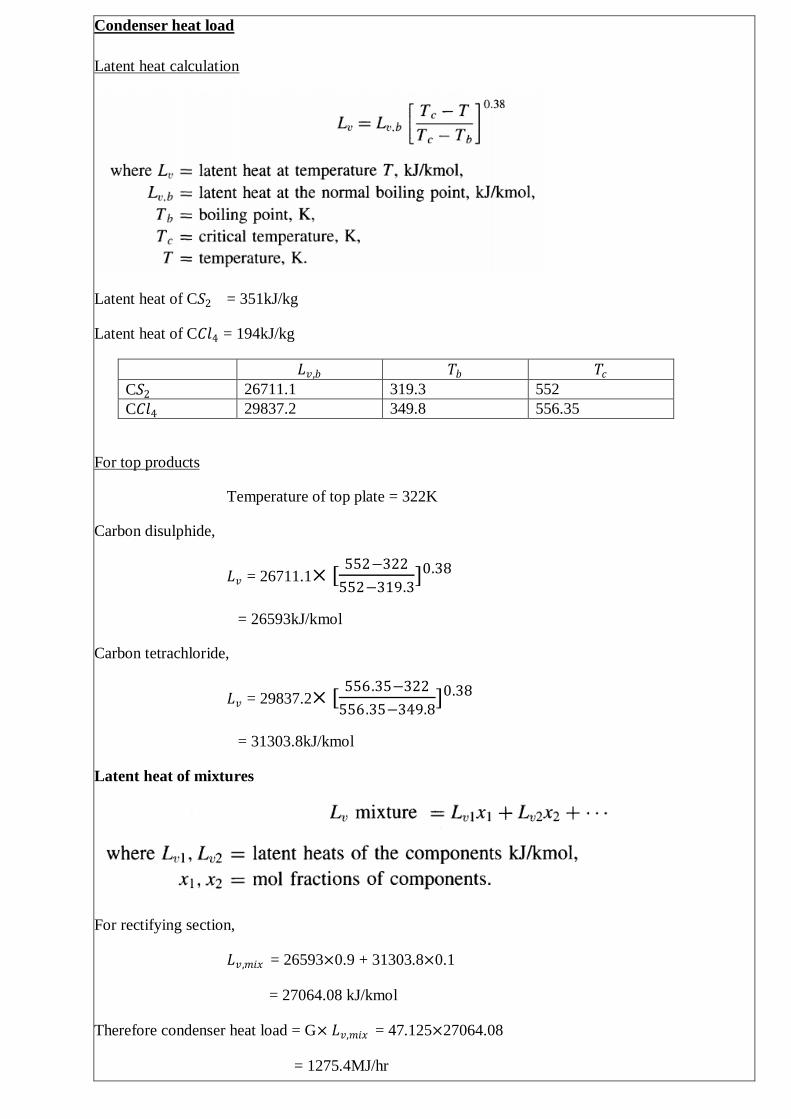
Condenser heat load
Latent heat calculation
Latent heat of C𝑆2 = 351kJ/kg
Latent heat of C𝐶𝑙4 = 194kJ/kg
𝐿𝑣,𝑏 𝑇𝑏 𝑇𝑐
C𝑆2 26711.1 319.3 552
C𝐶𝑙4 29837.2 349.8 556.35
For top products
Temperature of top plate = 322K
Carbon disulphide,
𝐿𝑣 = 26711.1× [552−322
552−319.3]0.38
= 26593kJ/kmol
Carbon tetrachloride,
𝐿𝑣 = 29837.2× [556.35−322
556.35−349.8]0.38
= 31303.8kJ/kmol
Latent heat of mixtures
For rectifying section,
𝐿𝑣,𝑚𝑖𝑥 = 26593×0.9 + 31303.8×0.1
= 27064.08 kJ/kmol
Therefore condenser heat load = G× 𝐿𝑣,𝑚𝑖𝑥 = 47.125×27064.08
= 1275.4MJ/hr

= 354.3kW
Boiler heat load calculation
Using equation,
𝑉𝑚𝐻𝑣 ,𝑚 + W𝐻𝑤 = 𝐿𝑚−1𝐻𝐿 ,𝑚−1 + 𝑄𝑅
𝐻𝑣 = 𝐻𝐿 + 𝜆𝑚𝑖𝑥
𝐻𝐿 = (𝐶1 + 𝐶2𝑇 + 𝐶3𝑇2 + 𝐶4𝑇
3)𝑑𝑇𝑇2
𝑇1
𝐶1 𝐶2 𝐶3 𝐶4
C𝑆2 85600 -122 0.5605 -0.001452
C𝐶𝑙4 -752700 8966.1 -30.394 0.034455
Average temperature of stripping section, T = 340.5K
Calculating the latent heat of mixture
For stripping section
Temperature of bottom plate = 348K
For Carbon disulphide,
𝐻𝐿 = (𝐶1 + 𝐶2𝑇 + 𝐶3𝑇2 + 𝐶4𝑇
3)𝑑𝑇𝑇2
𝑇1
= (85600 − 122T + 0.5605𝑇2 − 0.001452𝑇3)𝑑𝑇340.5
298
= 2397.325kJ/kmol
𝐿𝑣 = 26711.1× [552−340.5
552−319.3]0.38
= 25758.8kJ/kmol
Carbon tetrachloride,
𝐻𝐿 = (−752700 + 8966.1T − 30.394𝑇2 + 0.034455𝑇3)𝑑𝑇340 .5
298
= 5671.523kJ/kmol
𝐿𝑣 = 29837.2× [556.35−340.5
556.35−349.8]0.38
= 30340.7kJ/kmol
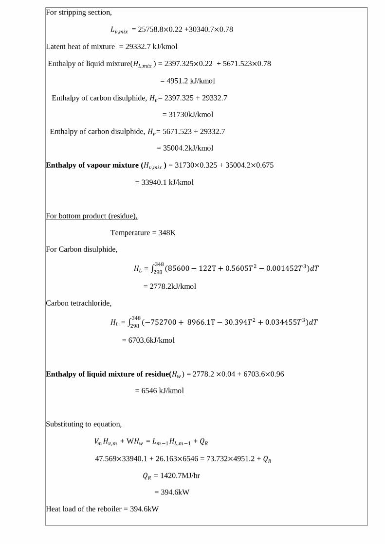
For stripping section,
𝐿𝑣,𝑚𝑖𝑥 = 25758.8×0.22 +30340.7×0.78
Latent heat of mixture = 29332.7 kJ/kmol
Enthalpy of liquid mixture(𝐻𝐿 ,𝑚𝑖𝑥 ) = 2397.325×0.22 + 5671.523×0.78
= 4951.2 kJ/kmol
Enthalpy of carbon disulphide, 𝐻𝑣= 2397.325 + 29332.7
= 31730kJ/kmol
Enthalpy of carbon disulphide, 𝐻𝑣= 5671.523 + 29332.7
= 35004.2kJ/kmol
Enthalpy of vapour mixture (𝐻𝑣,𝑚𝑖𝑥 ) = 31730×0.325 + 35004.2×0.675
= 33940.1 kJ/kmol
For bottom product (residue),
Temperature = 348K
For Carbon disulphide,
𝐻𝐿 = (85600 − 122T + 0.5605𝑇2 − 0.001452𝑇3)𝑑𝑇348
298
= 2778.2kJ/kmol
Carbon tetrachloride,
𝐻𝐿 = (−752700 + 8966.1T − 30.394𝑇2 + 0.034455𝑇3)𝑑𝑇348
298
= 6703.6kJ/kmol
Enthalpy of liquid mixture of residue(𝐻𝑤 ) = 2778.2 ×0.04 + 6703.6×0.96
= 6546 kJ/kmol
Substituting to equation,
𝑉𝑚𝐻𝑣,𝑚 + W𝐻𝑤 = 𝐿𝑚−1𝐻𝐿 ,𝑚−1 + 𝑄𝑅
47.569×33940.1 + 26.163×6546 = 73.732×4951.2 + 𝑄𝑅
𝑄𝑅 = 1420.7MJ/hr
= 394.6kW
Heat load of the reboiler = 394.6kW

Final data
Packing material plastic
Packing size 25mm
Pressure drop 62water mm/ m of packing
Reflux ratio 1.5262
Number of ideal stages 11
Column height 5.1m
Diameter of rectifying 0.388m
Diameter of stripping 0.296m
Feed tray location 3.45m from bottom
Condenser heat load 354.3kW
Reboiler heat load 394.6kW
Referencess
http://www.engineeringtoolbox.com/fluids-evaporation-latent-heat-d_147.html
http://www.britannica.com/EBchecked/topic/94993/carbon-disulfide-CS2
http://encyclopedia2.thefreedictionary.com/Carbon+Tetrachloride
CULSON & RICHARDSON’S, CHEMICAL ENGINEERING, Volume 6, 3rd
edition, R K
Sinnott
CULSON & RICHARDSON’S, CHEMICAL ENGINEERING, Volume 2, 5th edition
PERRY’S CHEMICAL ENGINEERS HAND BOOK, 8th edition, DON W. GREEN, ROBERT
H. PERRY
DISTILLATION DESIGN, HENRY Z. KISTER