Distal Humerus Locking Plate - Smith & Nephe Nota Bene The technique description herein is made...
32
Surgical Technique Distal Humerus Locking Plate
Transcript of Distal Humerus Locking Plate - Smith & Nephe Nota Bene The technique description herein is made...
Surgical Technique
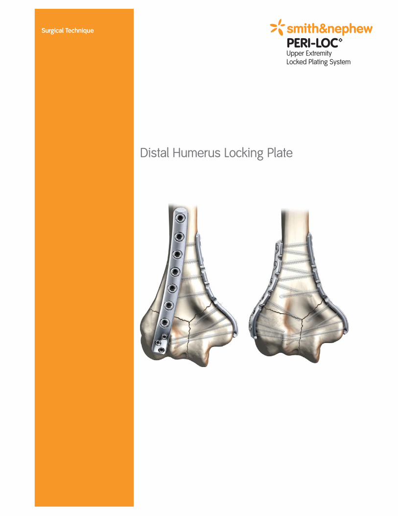
Distal Humerus Locking Plate


1
Nota BeneThe technique description herein is made available to the healthcare professionalto illustrate the author's suggested treatment for the uncomplicated procedure. In the final analysis, the preferred treatment is that which addresses the needs ofthe specific patient.
PERI-LOC™ Upper Extremity Locked Plating System
Distal Humerus Surgical Technique
Table of Contents
Introduction . . . . . . . . . . . . . . . . . . . . . . . . . . . . . . . . . . . . . . . . . . . . . . . . . . . . . . . .2
PERI-LOC Locked Plating System Overview . . . . . . . . . . . . . . . . . . . . . . . . . . . . . . . .2
Implant Features . . . . . . . . . . . . . . . . . . . . . . . . . . . . . . . . . . . . . . . . . . . . . . . . . . . . . .4
Indications . . . . . . . . . . . . . . . . . . . . . . . . . . . . . . . . . . . . . . . . . . . . . . . . . . . . . . . . . .5
Distal Humerus Case Examples . . . . . . . . . . . . . . . . . . . . . . . . . . . . . . . . . . . . . . . . .6
Surgical Technique . . . . . . . . . . . . . . . . . . . . . . . . . . . . . . . . . . . . . . . . . . . . . . . . . . .7
Patient Positioning . . . . . . . . . . . . . . . . . . . . . . . . . . . . . . . . . . . . . . . . . . . . . . . . . . . .7
Incision . . . . . . . . . . . . . . . . . . . . . . . . . . . . . . . . . . . . . . . . . . . . . . . . . . . . . . . . . . . . .8
Fracture Reduction and Provisional Fixation . . . . . . . . . . . . . . . . . . . . . . . . . . . . . . . .9
Plate Selection . . . . . . . . . . . . . . . . . . . . . . . . . . . . . . . . . . . . . . . . . . . . . . . . . . . . . . .10
Plate Positioning . . . . . . . . . . . . . . . . . . . . . . . . . . . . . . . . . . . . . . . . . . . . . . . . . . . . .12
Screw Insertion . . . . . . . . . . . . . . . . . . . . . . . . . . . . . . . . . . . . . . . . . . . . . . . . . . . . . . .13
• 2.7mm Cortex/Locking Screw Technique . . . . . . . . . . . . . . . . . . . . . . . . . . . . . . . . . .14
• 3.5mm Cortex/Locking Screw Technique . . . . . . . . . . . . . . . . . . . . . . . . . . . . . . . . . .16
Incision Closure . . . . . . . . . . . . . . . . . . . . . . . . . . . . . . . . . . . . . . . . . . . . . . . . . . . . . .18
Catalog Information . . . . . . . . . . . . . . . . . . . . . . . . . . . . . . . . . . . . . . . . . . . . . . . . . .19
2
Introduction
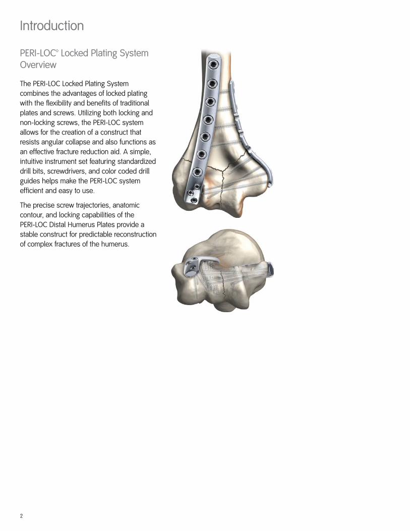
PERI-LOC™ Locked Plating SystemOverview
The PERI-LOC Locked Plating System
combines the advantages of locked plating
with the flexibility and benefits of traditional
plates and screws. Utilizing both locking and
non-locking screws, the PERI-LOC system
allows for the creation of a construct that
resists angular collapse and also functions as
an effective fracture reduction aid. A simple,
intuitive instrument set featuring standardized
drill bits, screwdrivers, and color coded drill
guides helps make the PERI-LOC system
efficient and easy to use.
The precise screw trajectories, anatomic
contour, and locking capabilities of the
PERI-LOC Distal Humerus Plates provide a
stable construct for predictable reconstruction
of complex fractures of the humerus.
3
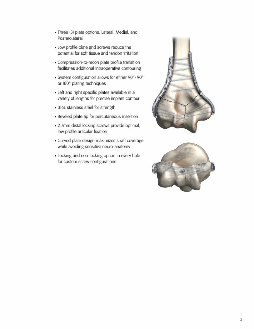
• Three (3) plate options: Lateral, Medial, and
Posterolateral
• Low profile plate and screws reduce the
potential for soft tissue and tendon irritation
• Compression-to-recon plate profile transition
facilitates additional intraoperative contouring
• System configuration allows for either 90°- 90°
or 180° plating techniques
• Left and right specific plates available in a
variety of lengths for precise implant contour
• 316L stainless steel for strength
• Beveled plate tip for percutaneous insertion
• 2.7mm distal locking screws provide optimal,
low profile articular fixation
• Curved plate design maximizes shaft coverage
while avoiding sensitive neuro-anatomy
• Locking and non-locking option in every hole
for custom screw configurations

Medial Plate
Beveled tip forpercutaneousinsertion
Recon platedesign for easycontouring
2.7mmarticularscrews
Implant Features
Lateral Plate
3.5mm ScrewHoles
Posterolateral
Plate
4
3.5mm Self-tapping Cortex Screw (Non-locking) Cat. No. 7182-40XXA
3.5mm Locking Self-tapping Cortex ScrewCat. No. 7182-50XX
2.7mm Self-tapping Cortex Screw (Non-locking)Cat. No. 7182-30XX
2.7mm Locking Self-tapping Cortex ScrewCat. No. 7182-23XX
Every threaded hole can accept a locking or non-locking screw:
5
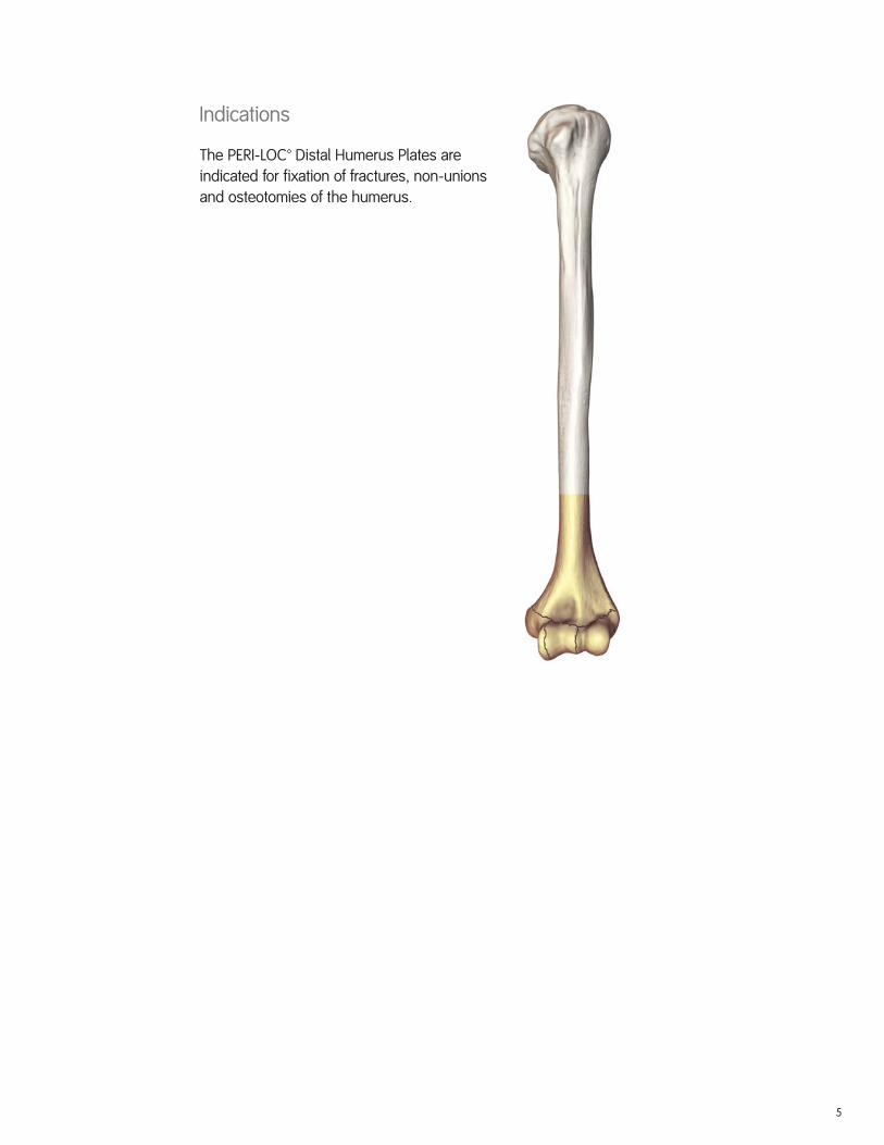
Indications
The PERI-LOC™ Distal Humerus Plates are
indicated for fixation of fractures, non-unions
and osteotomies of the humerus.

6
Distal Humerus Case Examples
Case 1

7
Surgical Technique
Patient Positioning
The patient may be placed in either the
lateral, prone, or supine position with the
involved limb supported over bolsters or an
elevated arm board placed parallel to the
table. A radiolucent table and arm board are
preferable so as not to impede fluoroscopy.
8
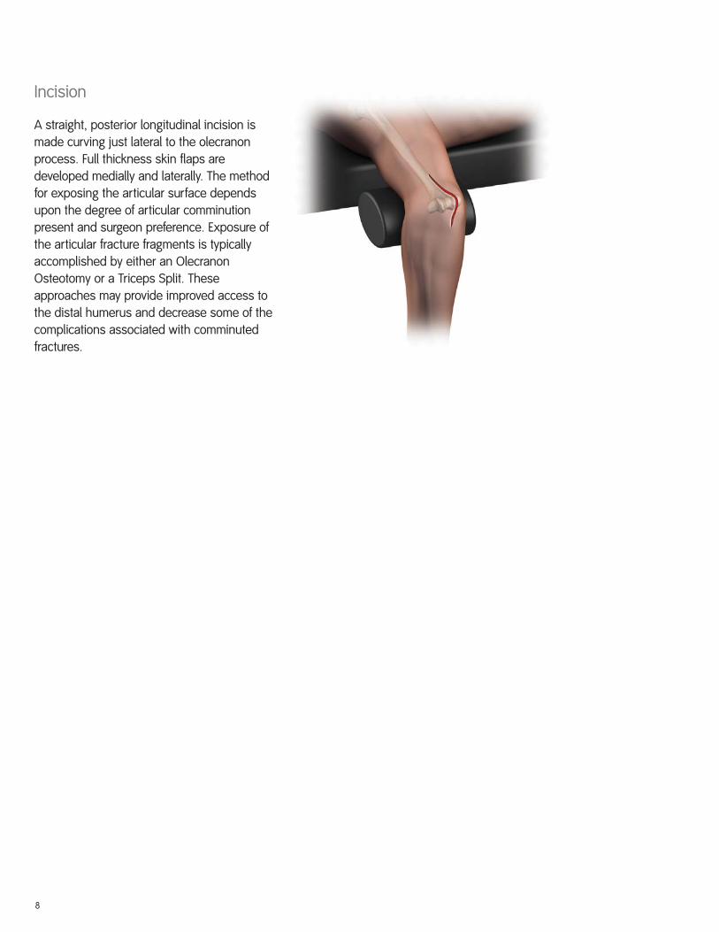
Incision
A straight, posterior longitudinal incision is
made curving just lateral to the olecranon
process. Full thickness skin flaps are
developed medially and laterally. The method
for exposing the articular surface depends
upon the degree of articular comminution
present and surgeon preference. Exposure of
the articular fracture fragments is typically
accomplished by either an Olecranon
Osteotomy or a Triceps Split. These
approaches may provide improved access to
the distal humerus and decrease some of the
complications associated with comminuted
fractures.

9
Fracture Reduction and ProvisionalFixation
After exposure and debridement of the fracture
site, the fracture is reduced and provisionally
fixed under fluoroscopy with K-wires, reduction
forceps or suture fixation. Reduction aids
should be placed so as not to interfere with
placement of the plate. The PERI-LOC™ Distal
Humerus Plates may also be used as reduction
tools due to their anatomical contour and
locking/non-locking screw options.

10
Plate Selection
The appropriate plate is selected following
fracture reduction. In general, the least
comminuted column of the humerus should
be reduced and fixed prior to the more
comminuted one. Fixation of distal humerus
fractures is typically achieved via a dual plate
construct. The PERI-LOC™ Distal Humerus
Plating System offers three anatomically
designed plates: Medial, Lateral and
Posterolateral, that may be configured into
90º-90º or 180º constructs depending on the
fracture pattern or surgeon preference.
Medial
Posterolateral
Lateral

11
Technique #2: The 180º approach
involves application of the Medial Distal
humeral plate to the medial column and
the Lateral Distal humeral plate to the
lateral column.
Technique #1: The 90º-90º approach involves
application of the Medial Distal humeral plate
to the medial column and the Posterolateral
Distal humeral plate to the lateral column.

12
Plate Positioning
Plate position on the distal humerus will be
dictated by fracture pattern and/or patient
anatomy and will differ according to the plating
configuration that was selected. Reduce the
fracture manually beginning with the least
comminuted column and confirm coronal and
sagittal alignment along with plate position on
the shaft. Proceed with application of the
second plate to the humerus followed by
confirmation of reduction and plate position.
Provisionally fix each plate to the proximal and
distal fracture fragments with Reduction
Forceps, K-wires and 2.7mm Provisional
Fixation Pins.
Note: It is imperative that the articular surface
of the distal humerus be reduced prior to
definitive fixation with any plates and screws.

13
Tips:
• If non-locking screws are to be inserted into a
plate to gain compression, it is preferred that
they be inserted prior to any locking screws.
• If either the 3.5mm Locking Screw Guide with
2.7mm Locking Drill Guide Insert or 2.7mm
Locking Screw Guide with 2.0mm Locking Drill
Guide Insert are used, remove the Drill Guide
Insert before inserting the appropriate length
screw through the slotted Outer Sleeve. Note
that the entire Drill Guide assembly must be
removed before inserting a screw less than
24mm in length. Advance the screw with the
appropriate Hexdriver until the black laser
etched marks are at the top of the Outer
Sleeve then remove the Outer Sleeve and
tighten by hand.
• For a pre-determined screw trajectory when
inserting Cortex Screws, either the 3.5mm
Locking Drill Guide with 2.7mm Insert or 2.7mm
Locking Drill Guide with 2.0mm Insert should
be used.
• The 3.5mm Locking Drill Guide–One Piece, and
2.0mm Locking Drill Guide–One Piece, may be
substituted for the Locking Drill Guides with
Inserts.
• Locking screws may be inserted on power, but
should always be tightened by hand. Tightening
screws on power may cause loss of reduction,
exposure of the screw head to excessive torque
or damage to the drill.
Screw Insertion
To visualize screw trajectories in the 2.7mm
distal locking holes, thread the 2.0mm Locking
Drill Guide into a screw hole and insert a 2.0mm
K-wire under fluoroscopy. The resultant image is
representative of the screw’s final trajectory.
Proceed with definitive fixation using appropriate
screw selections as detailed by the screw
insertion techniques listed to follow.
14
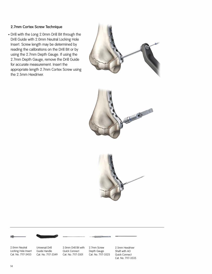
2.7mm Cortex Screw Technique
• Drill with the Long 2.0mm Drill Bit through the
Drill Guide with 2.0mm Neutral Locking Hole
Insert. Screw length may be determined by
reading the calibrations on the Drill Bit or by
using the 2.7mm Depth Gauge. If using the
2.7mm Depth Gauge, remove the Drill Guide
for accurate measurement. Insert the
appropriate length 2.7mm Cortex Screw using
the 2.5mm Hexdriver.
2.7mm ScrewDepth GaugeCat. No. 7117-3525
2.5mm HexdriverShaft with AOQuick ConnectCat. No. 7117-3535
2.0mm Drill Bit withQuick ConnectCat. No. 7117-3501
2.0mm NeutralLocking Hole Insert Cat. No. 7117-3453
Universal DrillGuide HandleCat. No. 7117-3349

15
2.7mm Locking Screw Technique
• Thread the 2.7mm Locking Screw Guide with
2.0mm Insert into one of the three (3) distal
locking holes. Drill with the Long 2.0mm Drill
Bit and measure for screw length by reading
the calibrations on the Drill Bit or by using the
2.7mm Depth Gauge. If using the Depth
Gauge, remove 2.0mm Drill Guide Insert.
Insert the appropriate length 2.7mm Locking
Screw using the 2.5mm Hexdriver.
2.5mm HexdriverShaft with AOQuick ConnectCat. No. 7117-3535
2.0mm Locking DrillGuide InsertCat. No. 7117-3449
2.7mm ScrewDepth GaugeCat. No. 7117-3525
2.0mm Drill Bit withQuick ConnectCat. No. 7117-3501
2.7mm LockingScrew GuideCat. No. 7117-3452

16
3.5mm Cortex Screw Technique
• Drill with the Long 2.7mm Drill Bit through the
Drill Guide with 2.7mm Neutral Locking Hole
Insert. Screw length may be determined by
reading the calibrations on the Drill Bit or by
using the 3.5mm Depth Gauge. If using the
Depth Gauge, remove the Locking Hole Insert for
accurate measurement. Insert the appropriate
length screw with the 3.5mm Hexdriver.
Short 3.5mm ScrewDepth GaugeCat. No. 7117-3523
3.5mm HexdriverShaft with AOQuick ConnectCat. No. 7117-3537
2.7mm Drill Bit withAO Quick ConnectCat. No. 7117-3503
2.7mm NeutralLocking Hole Insert Cat. No. 7117-3514
Universal DrillGuide HandleCat. No. 7117-3349

17
3.5mm Locking Screw Technique
• Thread the 3.5mm Locking Screw Guide with
Insert into the locking hole. Drill with the Long
2.7mm Drill Bit and measure for screw length by
reading the calibrations on the Drill Bit or by
using the 3.5mm Depth Gauge. If using Depth
Gauge, the Locking Drill Guide Insert must be
removed for accurate measurement. Insert the
appropriate length screw using the 3.5mm
Hexdriver.
2.7mm Locking DrillGuide InsertCat. No. 7117-3529
3.5mm LockingScrew GuideCat. No. 7117-3538
2.7mm Drill Bit withAO Quick ConnectCat. No. 7117-3503
Short 3.5mm ScrewDepth GaugeCat. No. 7117-3523
3.5mm HexdriverShaft with AOQuick ConnectCat. No. 7117-3537

18
Incision Closure
Verify fracture reduction under fluoroscopy and
use the appropriate method for surgical closure
of the incision.

19
Catalog Information – Elbow/2.7mm Plates
Plate TrayCat. No. 7117-0368
Medial Distal Humerus PlatesMinimum Maximum
Cat. No. Length Suggested Qty Tray Qty
7182-1805 5H Right 79mm 1 17182-1807 7H Right 103mm 1 17182-1809 9H Right 127mm 0 17182-1811 11H Right 151mm 0 17182-1813 13H Right 174mm 0 17182-1905 5H Left 79mm 1 17182-1907 7H Left 103mm 1 17182-1909 9H Left 127mm 0 17182-1911 11H Left 151mm 0 17182-1913 13H Left 174mm 0 1
Lateral Distal Humerus PlatesMinimum Maximum
Cat. No. Length Suggested Qty Tray Qty
7182-2405 5H Left 77mm 1 17182-2407 7H Left 102mm 1 17182-2409 9H Left 128mm 0 17182-2411 11H Left 153mm 1 17182-2505 5H Right 77mm 0 17182-2507 7H Right 102mm 1 17182-2509 9H Right 128mm 0 17182-2511 11H Right 153mm 1 1
Posterolateral Distal Humerus PlatesMinimum Maximum
Cat. No. Length Suggested Qty Tray Qty
7182-2605 5H Left 80mm 0 17182-2607 7H Left 107mm 1 17182-2609 9H Left 132mm 0 17182-2611 11H Left 157mm 1 17182-2615 15H Left 207mm 0 17182-2705 5H Right 80mm 0 17182-2707 7H Right 107mm 1 17182-2709 9H Right 132mm 0 17182-2711 11H Right 157mm 1 17182-2715 15H Right 207mm 0 1
PERI-LOC™ Ellbow/2.7mm Instrument setCat. No. 7181-1005
20
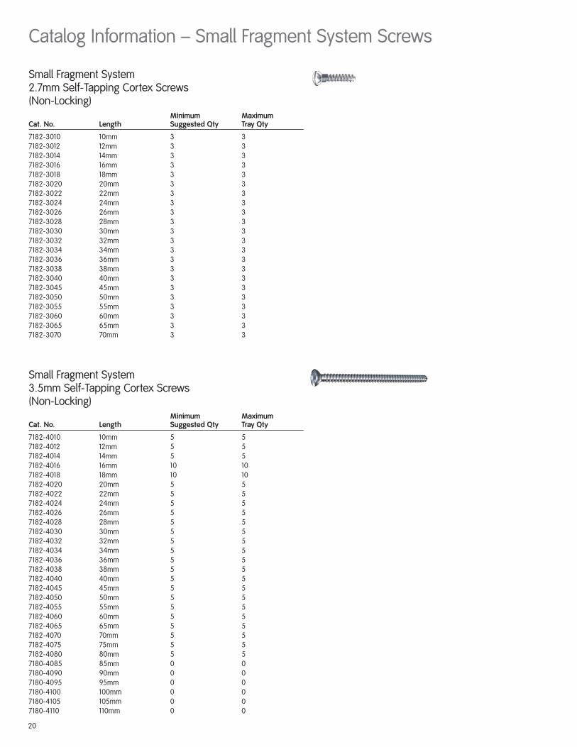
Small Fragment System3.5mm Self-Tapping Cortex Screws (Non-Locking)
Minimum Maximum Cat. No. Length Suggested Qty Tray Qty
7182-4010 10mm 5 57182-4012 12mm 5 57182-4014 14mm 5 57182-4016 16mm 10 107182-4018 18mm 10 107182-4020 20mm 5 57182-4022 22mm 5 57182-4024 24mm 5 57182-4026 26mm 5 57182-4028 28mm 5 57182-4030 30mm 5 57182-4032 32mm 5 57182-4034 34mm 5 57182-4036 36mm 5 57182-4038 38mm 5 57182-4040 40mm 5 57182-4045 45mm 5 57182-4050 50mm 5 57182-4055 55mm 5 57182-4060 60mm 5 57182-4065 65mm 5 57182-4070 70mm 5 57182-4075 75mm 5 57182-4080 80mm 5 57180-4085 85mm 0 07180-4090 90mm 0 07180-4095 95mm 0 07180-4100 100mm 0 07180-4105 105mm 0 07180-4110 110mm 0 0
Small Fragment System2.7mm Self-Tapping Cortex Screws (Non-Locking)
Minimum Maximum Cat. No. Length Suggested Qty Tray Qty
7182-3010 10mm 3 37182-3012 12mm 3 37182-3014 14mm 3 37182-3016 16mm 3 37182-3018 18mm 3 37182-3020 20mm 3 37182-3022 22mm 3 37182-3024 24mm 3 37182-3026 26mm 3 37182-3028 28mm 3 37182-3030 30mm 3 37182-3032 32mm 3 37182-3034 34mm 3 37182-3036 36mm 3 37182-3038 38mm 3 37182-3040 40mm 3 37182-3045 45mm 3 37182-3050 50mm 3 37182-3055 55mm 3 37182-3060 60mm 3 37182-3065 65mm 3 37182-3070 70mm 3 3
Catalog Information – Small Fragment System Screws

21
Small Fragment System3.5mm Locking Self-Tapping Cortex Screws
Minimum Maximum Cat. No. Length Suggested Qty Tray Qty
7182-5010 10mm 5 57182-5012 12mm 5 57182-5014 14mm 5 57182-5016 16mm 10 107182-5018 18mm 10 107182-5020 20mm 5 57182-5022 22mm 5 57182-5024 24mm 5 57182-5026 26mm 5 57182-5028 28mm 5 57182-5030 30mm 5 57182-5032 32mm 5 57182-5034 34mm 5 57182-5036 36mm 5 57182-5038 38mm 5 57182-5040 40mm 5 57182-5045 45mm 5 57182-5050 50mm 5 57182-5055 55mm 5 57182-5060 60mm 5 57182-5065 65mm 5 57182-5070 70mm 5 57182-5075 75mm 5 57182-5080 80mm 5 57180-5085 85mm 0 07180-5090 90mm 0 07180-5095 95mm 0 07180-5100 100mm 0 07180-5105 105mm 0 07180-5110 110mm 0 0
Small Fragment System2.7mm Locking Self-Tapping Cortex Screws
Minimum Maximum Cat. No. Length Suggested Qty Tray Qty
7182-2310 10mm 4 47182-2312 12mm 4 47182-2314 14mm 4 47182-2316 16mm 4 47182-2318 18mm 4 47182-2320 20mm 4 47182-2322 22mm 4 47182-2324 24mm 4 47182-2326 26mm 4 47182-2328 28mm 4 47182-2330 30mm 4 47182-2332 32mm 2 47182-2334 34mm 2 47182-2336 36mm 2 47182-2338 38mm 2 47182-2340 40mm 4 47182-2345 45mm 4 47182-2350 50mm 8 87182-2355 55mm 2 47182-2360 60mm 2 4

22
Catalog Information – Small Fragment System Instruments
Sharp HookCat. No. 7117-0043
Hohmann Retractor, 8mm WidthCat. No. 7117-0057
Hohmann Retractor Bent, 8mmCat. No. 7117-3369
Hohmann Retractor, 15mm WidthCat. No. 7117-0095
Wire Bending Pliers, 140mm LengthCat. No. 7117-0063
Bending Pliers for 2.7mm & 3.5mm PlatesCat. No. 7117-0076
Bending Pliers for 3.5mm Reconstruction PlatesCat. No. 7117-0175
Periosteal Elevator 6mm, RoundedCat. No. 7117-0097
Small Fragment CountersinkCat. No. 7117-3344
Universal Plate Bending IronsCat. No. 7117-3367
Reduction Forceps w/ Ratchet-Bowed, 205mmCat. No. 7117-3370
Reduction Forceps w/Points, BroadCat. No. 7117-3377

23
Reduction Forceps w/Serrated JawCat. No. 7117-3378
2.7mm Locking Drill Guide – One Piece(Optional)Cat. No. 7117-3450
3.5mm Locking Screw GuideCat. No. 7117-3538
2.7mm Compression Slot InsertCat. No. 7117-3511
Universal Drill Guide HandleCat. No. 7117-3349
2.7mm Neutral Slot InsertCat. No. 7117-3512
2.7mm Drill Guide InsertCat. No. 7117-3510
2.7mm Locking Drill Guide InsertCat. No. 7117-3529
3.5mm Drill Guide InsertCat. No. 7117-3513
2.7mm Neutral Locking Hole InsertCat. No. 7117-3514
2.7mm Compression Locking Hole InsertCat. No. 7117-3515
2.0mm Parallel Wire/Drill GuideCat. No. 7117-3516
2.0mm Wire/Drill InsertCat. No. 7117-3517
Short 3.5mm Screw Depth GaugeCat. No. 7117-3523
2.7mm Screw Depth GaugeCat. No. 7117-3525
3.5mm Screw Depth GaugeCat. No. 7117-3534

24
Cannulated Bending Irons for K-wiresCat. No. 7117-3527
Cannulated AO to Trinkle AdaptorCat. No. 7117-3528
2.5mm Hexdriver Shaft w/AO Quick ConnectCat. No. 7117-3535
Small T-Handle, Quick CouplingCat. No. 7117-3542
Tear Drop Handle Screwdriver w/Quick ConnectCat. No. 7117-3543
Self Centering Reverse Verbrugge, 190mmCat. No. 7117-3544
Large Screwdriver HandleCat. No. 7117-3547
Small Fragment Guide Removal AssemblyCat. No. 7117-3549
3.5mm Hexdriver Shaft w/AO Quick ConnectCat. No. 7117-3537
25
2.7mm Locking Screw GuideCat. No. 7117-3452
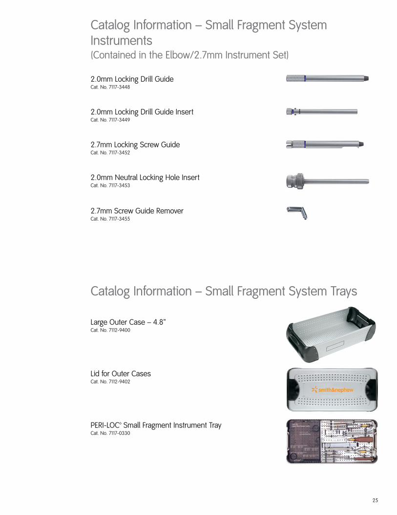
Large Outer Case – 4.8”Cat. No. 7112-9400
Lid for Outer CasesCat. No. 7112-9402
PERI-LOC™ Small Fragment Instrument TrayCat. No. 7117-0330
Catalog Information – Small Fragment System Trays
Catalog Information – Small Fragment SystemInstruments(Contained in the Elbow/2.7mm Instrument Set)
2.0mm Locking Drill GuideCat. No. 7117-3448
2.0mm Locking Drill Guide InsertCat. No. 7117-3449
2.0mm Neutral Locking Hole InsertCat. No. 7117-3453
2.7mm Screw Guide RemoverCat. No. 7117-3455

26
K-Wires with Trocar Point andThreaded Pins
MaximumCat. No. Description Tray Qty
7116-1012 1.25mm x 150mm 67116-1016 1.6mm x 150mm 67116-1020 2.0mm x 150mm 6
Taps with Quick ConnectMaximum
Cat. No. Description Tray Qty
7117-3318 3.5mm 27117-3366 2.7mm 27117-3386 4.0mm Cancellous 2
Provisional Fixation PinsMaximum
Cat. No. Description Tray Qty
7117-3322 2.7mm x 18mm 47117-3323 2.7mm x 40mm 4
Drill Bits with Quick ConnectMaximum
Cat. No. Description Tray Qty
7117-3501 2.0mm 27117-3502 2.7mm Short 27117-3503 2.7mm 27117-3504 3.5mm Short 2
Catalog Information – Small Fragment SystemDisposables


30023403027 7118-1093 09/06™Trademark of Smith & Nephew. Reg. US Pat. & TM Off.
Orthopaedic Trauma & Clinical TherapiesSmith & Nephew, Inc.1450 Brooks RoadMemphis, TN 38116USA
Telephone: 1-901-396-2121Information: 1-800-821-5700Orders/inquiries: 1-800-238-7538
www.smith-nephew.com