Disposable Sigfox solution USER GUIDE : SenLog · 2021. 3. 31. · Sigfox periodically with a...
22
Disposable Sigfox solution USER GUIDE : SenLog ESMT
Transcript of Disposable Sigfox solution USER GUIDE : SenLog · 2021. 3. 31. · Sigfox periodically with a...

Disposable Sigfox solution
USER GUIDE : SenLog
ESMT

ESMT Sigfox Solution Line Up
SenLog Operation Flow
Press Button to Start TX
YES
NO *3
Install Battery
Green LED
Sigfox TX
Sleep *2
Red LED
Data Logger *4
Press Button to Stop Sigfox
TX
Auto PWR ON to Sleep Mode
*1
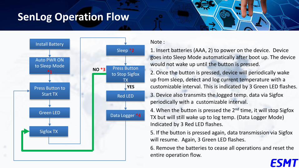
Note :
1. Insert batteries (AAA, 2) to power on the device. Device goes into Sleep Mode automatically after boot up. The device would not wake up until the button is pressed.
2. Once the button is pressed, device will periodically wake up from sleep, detect and log current temperature with a customizable interval. This is indicated by 3 Green LED flashes.
3. Device also transmits the logged temp. data via Sigfox periodically with a customizable interval.
4. When the button is pressed the 2nd time, it will stop Sigfox TX but will still wake up to log temp. (Data Logger Mode) Indicated by 3 Red LED flashes.
5. If the button is pressed again, data transmission via Sigfox will resume. Again, 3 Green LED flashes.
6. Remove the batteries to cease all operations and reset the entire operation flow.

SenLog PCBA
Battery Slots (AAA x 2) Activation Button
Note : The Micro USB connector is for dumping log data only. DO NOT connect it to a power source or otherwise the board will get burned out.

ESMT Sigfox Solution Payload
* 6 Bytes (8 Bytes : Optional) payload of Sigfox frame
Note :
1. The device takes temperature reading 2 times during a transmission interval, which is fixed at 10 min with current design. Each Sigfox TX frame carries up to 2 data points and therefore provides more information with less cost.
2. (Optional) Flag_C1 : permanent failure indicator to show that temp. has risen over temperature threshold for longer than the allow time threshold. For example, if temperature threshold is set at A℃, and time threshold is set at Y minutes, flag C1 will be raised if the detected temperature has been above A℃ and for longer than Y minutes.
3. (Optional) Flag_C2 : temporary failure indicator that shows a higher-than-threshold temperature has been detected. This flag could go back down if the next sample d temperature falls back below the threshold.
4. (Optional) Flag_D1 : temporary failure indicator that shows a Z degree higher-than-threshold temperature has been detected, where Z is configurable. For example, is the temperature threshold is set at 10 ℃ and Z is set to 5, then flash D1 will be raised if a temperature higher than 15 ℃ is detected.
5. (Optional) Flag_D2 : same as Flag_C2.
B0 B1 B2 B3 B4 B5 B6 B7
Temperature #1 - T1 ( @ t = 10 )
Temperature #2 - T2 ( @ t = 10 + 5 min. )
Temperature Threshold
(Optional) Temperature Alarm for
Customer
(Optional) Temperature Alarm for
Driver Battery
Capacity (%)
T1_Integer T1_Float T2_Integer T2_Float Flag_C1 Flag_C2 Flag_D1 Flag_D2
19 38 19 25 8A 0 *2 0 *3 0 *4 0 *5 00
25.56℃ 25.37℃ -10℃ 0 0 0 0 0

Battery
Press Button → Start Sigfox
Sigfox TX#1
Press Button → Stop Sigfox
Stop Sigfxo TX
Auto PWR ON → Sleep
….
ESMT Sigfox Solution Operation Flow (cont.)
t=0
Temp.(@0) Temp.(@10)
Sigfox TX#2
Sigfox TX#1 Payload = Temp.(@0)
Time(t) t=0 t=10min.
t=10min.
Sigfox TX#2 Payload = Temp.(@10)
Sigfox TX#3
Temp.(@20)
t=20min.
Sigfox TX#3 Payload = Temp.(@20)
t=20min.
Time(t)
This is an example of logging 1 data points within a 10 min transmission interval. The payload contains just 1 temp. data point.
Temperature Measurement
Sigfox Transmission

Battery
Press Button → Start Sigfox
Sigfox TX#1
Press Button → Stop Sigfox
Stop Sigfxo TX
Auto PWR ON → Sleep
….
ESMT Sigfox Solution Operation Flow (cont.)
Temp.(@5) Temp.(@10)
Sigfox TX#2
Sigfox TX#1 Payload = Temp.(@0) + Temp.(@0)
Time(t) t=0 t=10min.
Sigfox TX#2 Payload = Temp.(@5) + Temp.(@10)
Sigfox TX#3
Temp.(@15) Temp.(@20)
Sigfox TX#3 Payload = Temp.(@15) + Temp.(@20)
t=20min.
Time(t)
2 data points within a 10 min transmission interval. The payload contains 2 temp. data points: the one from right now and the one from 5 min ago.
Temp.(@0)
t=0 t=10min. t=20min. t=5min. t=15min.
Temperature Measurement
Sigfox Transmission

www.esmt.com.tw
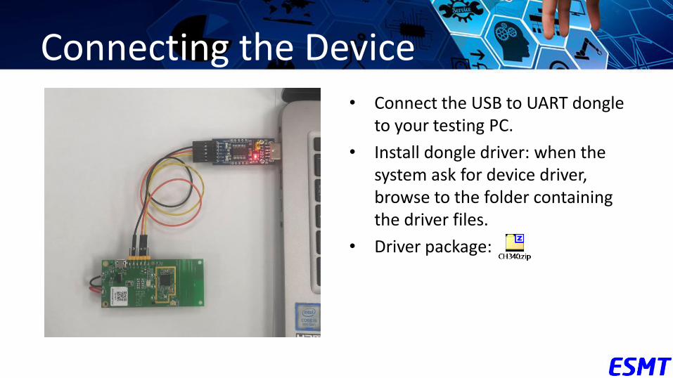
Connecting the Device • Connect the USB to UART dongle
to your testing PC.
• Install dongle driver: when the system ask for device driver, browse to the folder containing the driver files.
• Driver package:

Connecting the Device (cont.)
• Make sure you see this device on Device Manager.
• And remember the COM number (COM4 in this case) that the system assigns it. You will need it in the next step.
• If you don’t see this device, please check and make sure that the device driver has been installed correctly. You might have to install the driver again if the device didn’t show up on the system as shown after the first install. Don’t unplug it, just update the driver by browsing to the driver folder again.
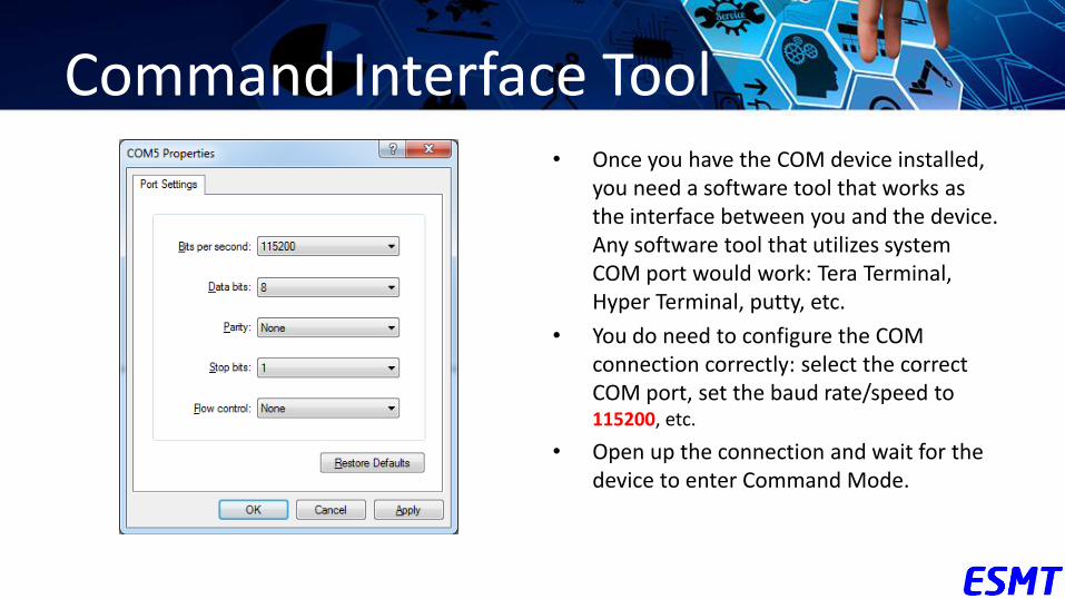
Command Interface Tool • Once you have the COM device installed,
you need a software tool that works as the interface between you and the device. Any software tool that utilizes system COM port would work: Tera Terminal, Hyper Terminal, putty, etc.
• You do need to configure the COM connection correctly: select the correct COM port, set the baud rate/speed to 115200, etc.
• Open up the connection and wait for the device to enter Command Mode.

Entering Boot/Command Mode
• In order to configure the device, you must boot it into boot/command mode.
• Steps: 1. Insert batteries.
2. Connect the UART interface cable to the PCBA as shown in the picture.
3. Insert Pin Jumper as shown in the picture to keep the chip’s Status Pin in low state. (Remember to remove the pin jumper after finished configuring the device.)
4. Send a reset signal to the chip with a brief contact (shouldn’t take more than 1 second)between the reset cable and the micro USB connector.

Command Mode • If done correctly, you want to see a
“BOOT> “ prompt on the terminal software interface almost immediately after you send the reset signal to the chip. Try pressing Enter a couple of times if you don’t see it.
• If you don’t see the prompt, reinstall the batteries and try sending the reset signal again (touch micro USB connector with the reset cable).
• At the BOOT> prompt, enter “jump” command to enter command mode.
• When you see the “UPLYNX>” prompt, it means you are in command mode and are ready to configure the device.

Current Settings: gcd • Once you have entered Command Mode,
the first thing you should do is checking the current settings of the device. This is done by entering the command gcd.
• The result is a list of the current settings as shown in the picture.
• In the following slides, relative parameters will be explained in details.
• Please keep in that the default values of the configurable parameters

Setting Current Time • The command to set the current time is
rtc:
– Format: rtc [YY] [MM] [DD] [HH] [mm] [ss]
• The example on the left sets the current time at 15:41:30, March 10, 2021
• Check the RTC Start Time parameter in the gcd command print-out to make sure the time was set as desired.

Setting Temperature Threshold: wtmp
• This command sets the temperature threshold.
• The command is wtmp :
– Syntax : wtmp [temp], temp = -10 ~ 60
• The example on the left sets the threshold, or the Warning Temp parameter, to 5 ℃.

Setting time threshold: otpx
• The device must be allowed some time to reach a balance with its surrounding after it’s activated in order to report/log the correct temperature data. Therefore, a start delay is added right after when the device is activated and before it actually starts to operate. This is the “OVT Period X” parameter and it’s configurable.
• Syntax:
– otpx [value], value = 1 ~255
• The example on the left sets the parameter to 3. This delay is calculated by multiplying the transmission interval by the value:
– 10 min * 3 = 30 minutes
• This means that once the button is pressed and device is activated, the device will start to log/report data 30 minutes later.

Setting time threshold: otpy
• This sets the “time” component, or the time threshold, for the C1 flag.
• Syntax:
– otpy [value], value = 1 ~255
• Represented by “OVT Period Y” param.
• The time threshold is calculated by multiplying the transmission interval (fixed at 10 minutes) by this value. In the example the time threshold is set at 10 min * 3 = 30 minutes.
• The combination of time and temp. threshold gets you the condition for raising C1 flag. In this example, if the temperature detected is above 5 ℃ for over 30 min, C1 flag is raised.

Setting Abnormal Range: otth
• Flag D1 is raised if the sampled temperature is greater than temperature threshold + abnormal range.
• Syntax : otth [temp], temp = 1 ~255
• The example on the left sets the Abnormal Range at Z = 10 ℃, which means that flag D1 will be raised if a temperature 10 ℃ higher than the temperature threshold has been detected.
• Corresponds to the “Abnormal Range “ field.
Extract log data
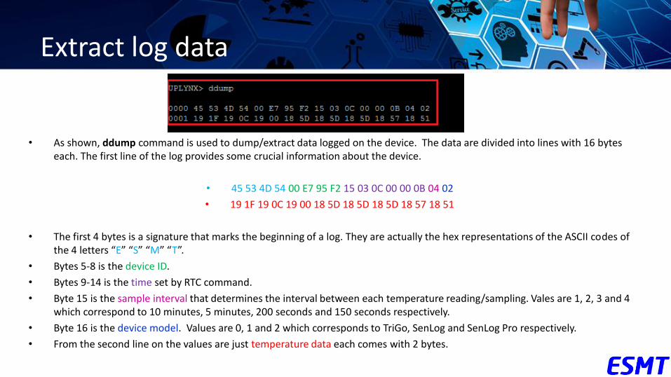
• As shown, ddump command is used to dump/extract data logged on the device. The data are divided into lines with 16 bytes each. The first line of the log provides some crucial information about the device.
• 45 53 4D 54 00 E7 95 F2 15 03 0C 00 00 0B 04 02
• 19 1F 19 0C 19 00 18 5D 18 5D 18 5D 18 57 18 51
• The first 4 bytes is a signature that marks the beginning of a log. They are actually the hex representations of the ASCII codes of the 4 letters “E” “S” “M” “T”.
• Bytes 5-8 is the device ID.
• Bytes 9-14 is the time set by RTC command.
• Byte 15 is the sample interval that determines the interval between each temperature reading/sampling. Vales are 1, 2, 3 and 4 which correspond to 10 minutes, 5 minutes, 200 seconds and 150 seconds respectively.
• Byte 16 is the device model. Values are 0, 1 and 2 which corresponds to TriGo, SenLog and SenLog Pro respectively.
• From the second line on the values are just temperature data each comes with 2 bytes.

Erasing logged temperature data
• To logged temperature data could be erased from the internal storage with the command dre.

Save and double check settings
• Once you have finished modifying the configurations and double checked with gcd command, type save command to make sure the settings are actually stored.
• Remember to remove the pin jumper before restarting the device (by removing and reinserting the batteries) to apply the new settings.