Displacement estimation of bridge structures using data ... · that may have complex shapes,...
19
Smart Structures and Systems, Vol. 15, No. 3 (2015) 645-663 DOI: http://dx.doi.org/10.12989/sss.2015.15.3.645 645 Copyright © 2015 Techno-Press, Ltd. http://www.techno-press.org/?journal=sss&subpage=8 ISSN: 1738-1584 (Print), 1738-1991 (Online) Displacement estimation of bridge structures using data fusion of acceleration and strain measurement incorporating finite element model Soojin Cho, Chung-Bang Yun and Sung-Han Sim School of Urban and Environmental Engineering, Ulsan National Institute of Science and Technology (UNIST), Ulsan 689-798, Republic of Korea (Received November 5, 2014, Revised February 10, 2014, Accepted February 12, 2015) Abstract. Recently, an indirect displacement estimation method using data fusion of acceleration and strain (i.e., acceleration-strain-based method) has been developed. Though the method showed good performance on beam-like structures, it has inherent limitation in applying to more general types of bridges that may have complex shapes, because it uses assumed analytical (sinusoidal) mode shapes to map the measured strain into displacement. This paper proposes an improved displacement estimation method that can be applied to more general types of bridges by building the mapping using the finite element model of the structure rather than using the assumed sinusoidal mode shapes. The performance of the proposed method is evaluated by numerical simulations on a deck arch bridge model and a three-span truss bridge model whose mode shapes are difficult to express as analytical functions. The displacements are estimated by acceleration-based method, strain-based method, acceleration-strain-based method, and the improved method. Then the results are compared with the exact displacement. An experimental validation is also carried out on a prestressed concrete girder bridge. The proposed method is found to provide the best estimate for dynamic displacements in the comparison, showing good agreement with the measurements as well. Keywords: Displacement; bridge; data fusion; finite element model; modal mapping 1. Introduction Displacement is an intuitive response that directly results from external loads to a structure. Despite of its close relationship with health of a structure, displacement has not been popularly used in structural health monitoring (SHM) of full-scale civil engineering structures unlike other responses such as acceleration (Doebling et al. 1998, Bani-Hani et al. 2008, Altunisik et al. 2012) and strain (Omenzetter et al. 2004, Majumder et al. 2008, Sigurdardottir and Glisic 2014); a limited number of literatures have reported the use of displacement for monitoring of civil structures (Faulkner et al. 1996, Celibi 2000, Xu et al. 2002, Nassif et al. 2005, Lee et al. 2007). The literatures, however, exhibit that the usage is limited to the measurements at a few locations, which is incapable of providing rich information necessary to assess comprehensive structural Corresponding author, Assistant Professor, E-mail: [email protected]
Transcript of Displacement estimation of bridge structures using data ... · that may have complex shapes,...
Smart Structures and Systems, Vol. 15, No. 3 (2015) 645-663 DOI: http://dx.doi.org/10.12989/sss.2015.15.3.645 645
Copyright © 2015 Techno-Press, Ltd. http://www.techno-press.org/?journal=sss&subpage=8 ISSN: 1738-1584 (Print), 1738-1991 (Online)
Displacement estimation of bridge structures using data fusion of acceleration and strain measurement incorporating finite
element model
Soojin Cho, Chung-Bang Yun and Sung-Han Sim
School of Urban and Environmental Engineering, Ulsan National Institute of Science and Technology (UNIST), Ulsan 689-798, Republic of Korea
(Received November 5, 2014, Revised February 10, 2014, Accepted February 12, 2015)
Abstract. Recently, an indirect displacement estimation method using data fusion of acceleration and strain (i.e., acceleration-strain-based method) has been developed. Though the method showed good performance on beam-like structures, it has inherent limitation in applying to more general types of bridges that may have complex shapes, because it uses assumed analytical (sinusoidal) mode shapes to map the measured strain into displacement. This paper proposes an improved displacement estimation method that can be applied to more general types of bridges by building the mapping using the finite element model of the structure rather than using the assumed sinusoidal mode shapes. The performance of the proposed method is evaluated by numerical simulations on a deck arch bridge model and a three-span truss bridge model whose mode shapes are difficult to express as analytical functions. The displacements are estimated by acceleration-based method, strain-based method, acceleration-strain-based method, and the improved method. Then the results are compared with the exact displacement. An experimental validation is also carried out on a prestressed concrete girder bridge. The proposed method is found to provide the best estimate for dynamic displacements in the comparison, showing good agreement with the measurements as well.
Keywords: Displacement; bridge; data fusion; finite element model; modal mapping
1. Introduction
Displacement is an intuitive response that directly results from external loads to a structure. Despite of its close relationship with health of a structure, displacement has not been popularly used in structural health monitoring (SHM) of full-scale civil engineering structures unlike other responses such as acceleration (Doebling et al. 1998, Bani-Hani et al. 2008, Altunisik et al. 2012) and strain (Omenzetter et al. 2004, Majumder et al. 2008, Sigurdardottir and Glisic 2014); a limited number of literatures have reported the use of displacement for monitoring of civil structures (Faulkner et al. 1996, Celibi 2000, Xu et al. 2002, Nassif et al. 2005, Lee et al. 2007). The literatures, however, exhibit that the usage is limited to the measurements at a few locations, which is incapable of providing rich information necessary to assess comprehensive structural
Corresponding author, Assistant Professor, E-mail: [email protected]

Soojin Cho, Chung-Bang Yun and Sung-Han Sim
health.
The usage of displacement has been restricted in full-scale civil structures due to measurement
inconvenience and high cost of measurement devices. The traditional contact-type transducers,
such as a linear variable differential transformer (LVDT) and a ring type transducer, measure
displacements from the deformation of an elastic part of the transducer that is contacted to the
structure. The contact-type transducers are inexpensive, but require reference points to fix the
transducer firmly when the host structure is deforming. In many cases, some fixtures such as
scaffolds are installed around the structure to bind the transducers, which is labor intensive and
often unavailable due to operational condition of the structure. Even the fixtures may be deformed
by an external force such as wind. Noncontact-type devices, such as the global positioning system
(GPS) and the laser Doppler vibrometer (LDV), have been emerged as alternatives (Nassif et al.
2005, Jo et al. 2013). However, high cost of the devices up to a few ten thousand dollars per
sensing channel still limits their real-world applications with a dense topology.
To overcome the inherent limitations of displacement transducers, indirect displacement
estimation approaches have alternatively been studied to use other responses that can be converted
to the displacement. Acceleration and strain are the most popular responses in the studies.
Acceleration is an absolute response that can be easily captured on a structure without having a
fixed reference. Theoretically, acceleration can be converted into displacement by double
integration in the time domain, while the numerical integration generally brings a significant signal
drift (Park et al. 2005, Gindy et al. 2008, Kandula et al. 2012). Lee et al. (2010) successfully
proposed an FIR filter-based displacement estimation technique which regularizes the signal drift.
However, the acceleration-displacement conversion is based on the low-pass filter that eliminates
the signal drift with true low frequency component contained in the displacement signal. Thus, the
acceleration-based technique fails to estimate displacement with the static or pseudo-static
components. Unlike the acceleration, strain can estimate the static or pseudo-static displacement in
nature as the time integration is uninvolved in the conversion. Displacement may be estimated
from strain using double spatial integration in space when the strain is measured on a structure in
the distributed manner (Chung et al. 2008) or using the modal mapping between a strain and
displacement (Foss and Hauge 1995). Since the modal mapping may construct dynamic
displacement from a few measured dynamic strain data based on the modal information, it is very
useful to estimate displacements at arbitrary locations on the structure when its modal information
is available. Instead of using modal information measured by densely deployed sensors, Kang et al.
(2007) used mode shapes from the finite element (FE) model of a structure and Shin et al. (2012)
used assumed sinusoidal mode shapes for a simple beam-type structure. The strain does not cause
the signal drift in time domain during the conversion to displacement, while its measurement is
vulnerable to measurement noise in high frequency range. Furthermore, the strain-based method
requires determination of neutral axis of the structure (Shin et al. 2012).
Park et al. (2013) proposed a displacement estimation method using data fusion of acceleration
and strain by extending the acceleration-based method proposed by Lee et al. (2010). In the
regularization term, the displacement converted from strain data by the modal mapping is used to
prevent the signal drift. For the modal mapping, the assumed analytical (sinusoidal) mode shapes
proposed by Shin et al. (2012) are employed. The method by Park et al. (2013), however, inherits
a limitation in application to more general types of bridges with complex shapes, such as arch and
truss bridges, since the method uses assumed sinusoidal mode shapes which may be reasonably
obtained only for the girder bridges.
This study proposes an improved method to estimate the accurate displacement using
646
Displacement estimation of bridge structures using data fusion of acceleration…
acceleration and strain for general bridge structures. The proposed method is to extend the method
by Park et al. (2013) to general types of bridges by using the mode shapes for the modal mapping
from the FE model of a structure instead of assumed sinusoidal mode shapes. The performance of
the proposed method is evaluated by numerical simulations on a deck arch bridge model and a
three-span truss bridge model whose mode shapes are hard to be assumed as sinusoidal functions.
The displacements are estimated by acceleration-based method, strain-based method, fusion-based
method, and the improved method, and the results are compared with exact displacements to
demonstrate the performance of the proposed method. Then, the method is experimentally
validated from a field testing on a prestressed concrete bridge. From the comparison of
displacements estimated by the four methods to the reference values measured by laser
displacement meters, the accuracy of the proposed method has been investigated. The proposed
method makes the displacement measurement facilitated (without the reference points),
inexpensive, and accurate.
2. Improved displacement estimation method using acceleration and strain
This section describes the principles of the displacement estimation method proposed by Park
et al. (2013) and the modification made in the proposed method.
2.1 Acceleration-strain-based displacement estimation method Park et al. (2013) have proposed the displacement estimation method by fusing the acceleration
and strain. The method uses the basic form of the acceleration-based method proposed by Lee et al.
(2010), while the regularization term is replaced by the difference between estimated
displacements and displacement estimated from the strain by modal mapping method. The method
can be formulated for displacement u i at the location of ix as
22 2
2 T
2 2
1Min ( ( ) )
2 2uL L u a u εD
i
a c i i i it
(1)
where ( 2) 1
uN
i
¡ and 1
aN
i
¡ are the estimated displacement and measured acceleration at
the location ix ; ( 2)ε
N n ¡ is the strain measured at n locations; N is the number of
acceleration data to be converted into displacement; t is the time step; LN N
a
¡ is a
diagonal weighting matrix having the first and last entries as 1/ 2 and the other entries as 1;( 2)
LN N
c
¡ is the second-order differential operator matrix of the discretized trapezoidal rule
(Atkinson 2008); 2 is2-norm of a vector; is a regularization factor; and 1
Dn
i
¡ is the i th
row of modal mapping matrix Dm n¡ that converts strain into displacement as
T Tu Dε (2)
where ( 2)u
N m ¡ is the displacement obtained at m locations. The modal mapping matrix can
be calculated as
†
D ΦΨ (3)
647

Soojin Cho, Chung-Bang Yun and Sung-Han Sim
where Φ m r¡ and Ψ n r¡ denote mode shape vector and strain mode shapes, respectively;
the superscript † denotes the pseudo-inverse; and r is the number of used modes that is equal
to or smaller than n to avoid an under-determined modal mapping matrix. Note that the number
of modes n used in the estimation can be determined based on dominant modes in the
displacement being estimated. is defined by Lee et al. (2010) as
1.9546.81N (4)
The mode shapes and strain mode shapes may be directly estimated from measurements, which
would be very expensive. Instead, Park et al. (2013) employed assumed sinusoidal mode shapes
and corresponding strain mode shapes, proposed by Shin et al. (2012), as
1 1sin sin
sin sin
Φassumed
m m
x r x
l l
x r x
l l
L
M O M
L
(5)
21 1
2
2
2
sin sin
sin sin
Ψassumed
n n
z r zr
l ly
lz r z
rl l
L
M O M
L
(6)
where ( 1, , )ix i m L and ( 1, , )iz i n L are the locations where acceleration and strain are
measured, respectively; y is the distance from the neutral axis to the surface where strain gauges
are installed; and l is length of the structure. The neutral axis y can be determined by the
calibration technique that uses both acceleration and strain, which was proposed by Park et al.
(2013). The solution of Eq. (1) can be expressed as
2 1 2 2 T( λ ) ( λ )u L L I L L a εDT T
i a i it (7)
where L L La c . Note that Lee et al. (2010) suggested a moving-window strategy to address the
inaccurate estimation near the boundaries of the finite data, which was also adapted by Park et al.
(2013). The optimal size of moving window is proposed as three times the number of data points
in the first natural period after numerical simulation tests on various systems in Lee et al. (2010).
2.2 Improved method using modal mapping from finite element model
The acceleration-strain-based method (described in the previous section) builds the modal
mapping matrix D using the assumed sinusoidal mode shapes as in Eqs. (5) and (6). In the case
of prismatic or nearly-prismatic simply-supported beams, the sinusoidal mode shapes approximate
the real ones reasonably. For example, Shin et al. (2012) successfully estimated displacement from
the measured strain on a single-span bridge using the assumed sinusoidal mode shapes. Park et al.
(2013) also validated their method on a suspension bridge in the experiment. Both bridges have
648
Displacement estimation of bridge structures using data fusion of acceleration…
prismatic or nearly-prismatic sections and large span-to-depth ratios, and thus have the mode
shapes quite close to the assumed sinusoidal shapes.
However, possible disagreements of the assumed mode shapes to the real mode shapes can
happen in general types of structures, causing significant errors in the displacement estimation.
The errors can be minimized by obtaining the real mode shapes and strain mode shapes from a
dense array of accelerometers and strain gages, but it is not practical due to high cost. If the mode
shapes and strain mode shapes can be assumed reasonably based on the physical insight of the
structure, then they can minimize the error up to the acceptable level.
In this paper, an improved method is proposed by employing a modal mapping matrix derived
from an FE model of the structure as
†( )D Φ Ψ
FE FE (8)
where ΦFE m r¡ and ΨFE n r¡ are the mode shapes and the strain mode shapes obtained
from the FE model. Since ΦFE and ΨFE replace Φ and Ψ of Eqs. (5) and (6) in the
improved method, the mode shapes and the strain mode shapes need to be estimated from the FE
model for locations where the displacement is to be estimated (i.e., the accelerations are measured)
and where the strains are measured, respectively.
The accuracy of the estimated displacement can be quantified by employing a percentage root
mean square deviation (RMSD) as
2
1
2
1
( )
(%) 100
( )
Nest ref
ij ij
j
Nref
ij
j
u u
RMSD
u
(9)
where est
iju and ref
iju are the estimated and reference displacements at location ix , respectively.
3. Numerical validation
The improved method is validated from numerical simulations carried out on two example
structures: an open-spandrel deck arch bridge model and a 3-span truss bridge model. The
displacements excited by a moving load are estimated by four methods: i.e., acceleration-based
method (Lee et al. 2010), strain-based method (Kang et al. 2007), acceleration-strain-based
method (Park et al. 2013), and the improved acceleration-strain-based method, and the results are
compared for the validation.
3.1 Deck arch bridge model
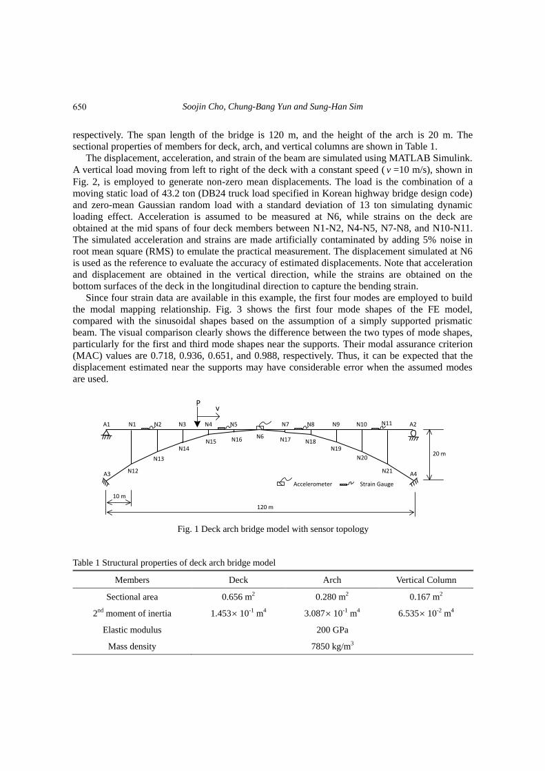
The first example used in this study is a 2D open-spandrel deck arch bridge model shown in
Fig. 1. The model has a deck which locates above the arch and the deck is supported by a number
of vertical columns rising from the arch. The Rainbow Bridge at Niagara Falls and the Cold Spring
Canyon Arch Bridge are the famous examples of the deck arch bridges.
The model is composed of 34 members: 12 deck members, 12 arch members, and 10 vertical
columns. All members are modelled as frame elements. N# and A# denote the nodes and supports,
649
Soojin Cho, Chung-Bang Yun and Sung-Han Sim
respectively. The span length of the bridge is 120 m, and the height of the arch is 20 m. The
sectional properties of members for deck, arch, and vertical columns are shown in Table 1.
The displacement, acceleration, and strain of the beam are simulated using MATLAB Simulink.
A vertical load moving from left to right of the deck with a constant speed ( v =10 m/s), shown in
Fig. 2, is employed to generate non-zero mean displacements. The load is the combination of a
moving static load of 43.2 ton (DB24 truck load specified in Korean highway bridge design code)
and zero-mean Gaussian random load with a standard deviation of 13 ton simulating dynamic
loading effect. Acceleration is assumed to be measured at N6, while strains on the deck are
obtained at the mid spans of four deck members between N1-N2, N4-N5, N7-N8, and N10-N11.
The simulated acceleration and strains are made artificially contaminated by adding 5% noise in
root mean square (RMS) to emulate the practical measurement. The displacement simulated at N6
is used as the reference to evaluate the accuracy of estimated displacements. Note that acceleration
and displacement are obtained in the vertical direction, while the strains are obtained on the
bottom surfaces of the deck in the longitudinal direction to capture the bending strain.
Since four strain data are available in this example, the first four modes are employed to build
the modal mapping relationship. Fig. 3 shows the first four mode shapes of the FE model,
compared with the sinusoidal shapes based on the assumption of a simply supported prismatic
beam. The visual comparison clearly shows the difference between the two types of mode shapes,
particularly for the first and third mode shapes near the supports. Their modal assurance criterion
(MAC) values are 0.718, 0.936, 0.651, and 0.988, respectively. Thus, it can be expected that the
displacement estimated near the supports may have considerable error when the assumed modes
are used.
Fig. 1 Deck arch bridge model with sensor topology
Table 1 Structural properties of deck arch bridge model
Members Deck Arch Vertical Column
Sectional area 0.656 m2 0.280 m2 0.167 m2
2nd moment of inertia 1.453 10-1 m4 3.087 10-1 m4 6.535 10-2 m4
Elastic modulus 200 GPa
Mass density 7850 kg/m3
Accelerometer Strain Gauge
N1 N2 N3 N4 N5
N6
N7 N8 N9 N10 N11A1 A2
Pv
120 m
10 m
20 m
N12
N13
N14N15 N16 N17 N18
N19
N20
N21A3 A4
650

Displacement estimation of bridge structures using data fusion of acceleration…
Fig. 2 Simulated vertical moving load
Fig. 3 First four mode shapes of FE model (solid lines) compared with assumed ones (dashed lines)
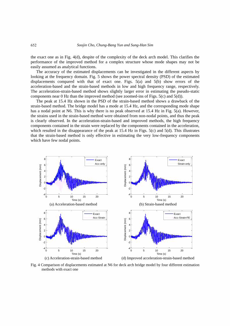
3.1.1 Comparison of displacements at N6 Fig. 4 shows the comparison of the displacements estimated by four methods with exact one
simulated from the MATLAB Simulink. The acceleration-based method can not estimate the
nonzero-mean pseudo-static displacement component as shown in Fig. 4(a). The strain-based
method can somewhat estimate the static component as shown in Fig. 4(b), while the dynamic
component cannot be estimated accurately. The acceleration-strain-based method gives an
incorrect displacement due to the incorrect modal mapping as in Fig. 4(c). Meanwhile, the
improved acceleration-strain-based method estimates very accurate displacement overlapped with
0 5 10 15 20
0246
x 104
Loadin
g a
t N
1
0 5 10 15 20
0246
x 104
Loadin
g a
t N
2
0 5 10 15 20
0246
x 104
Loadin
g a
t N
3
0 5 10 15 20
0246
x 104
Loadin
g a
t N
11
0 5 10 15 20
0246
x 104
Loadin
g a
t N
23
time (sec)
0 5 10 15 20
0246
x 104
Loadin
g a
t N
10 5 10 15 20
0246
x 104
Loadin
g a
t N
2
0 5 10 15 20
0246
x 104
Loadin
g a
t N
3
0 5 10 15 20
0246
x 104
Loadin
g a
t N
11
0 5 10 15 20
0246
x 104
Loadin
g a
t N
23
time (sec)
0 5 10 15 20
0246
x 104
Loadin
g a
t N
10 5 10 15 20
0246
x 104
Loadin
g a
t N
2
0 5 10 15 20
0246
x 104
Loadin
g a
t N
3
0 5 10 15 20
0246
x 104
Loadin
g a
t N
11
0 5 10 15 20
0246
x 104
Loadin
g a
t N
23
time (sec)
651
Soojin Cho, Chung-Bang Yun and Sung-Han Sim
the exact one as in Fig. 4(d), despite of the complexity of the deck arch model. This clarifies the
performance of the improved method for a complex structure whose mode shapes may not be
easily assumed as analytical functions.
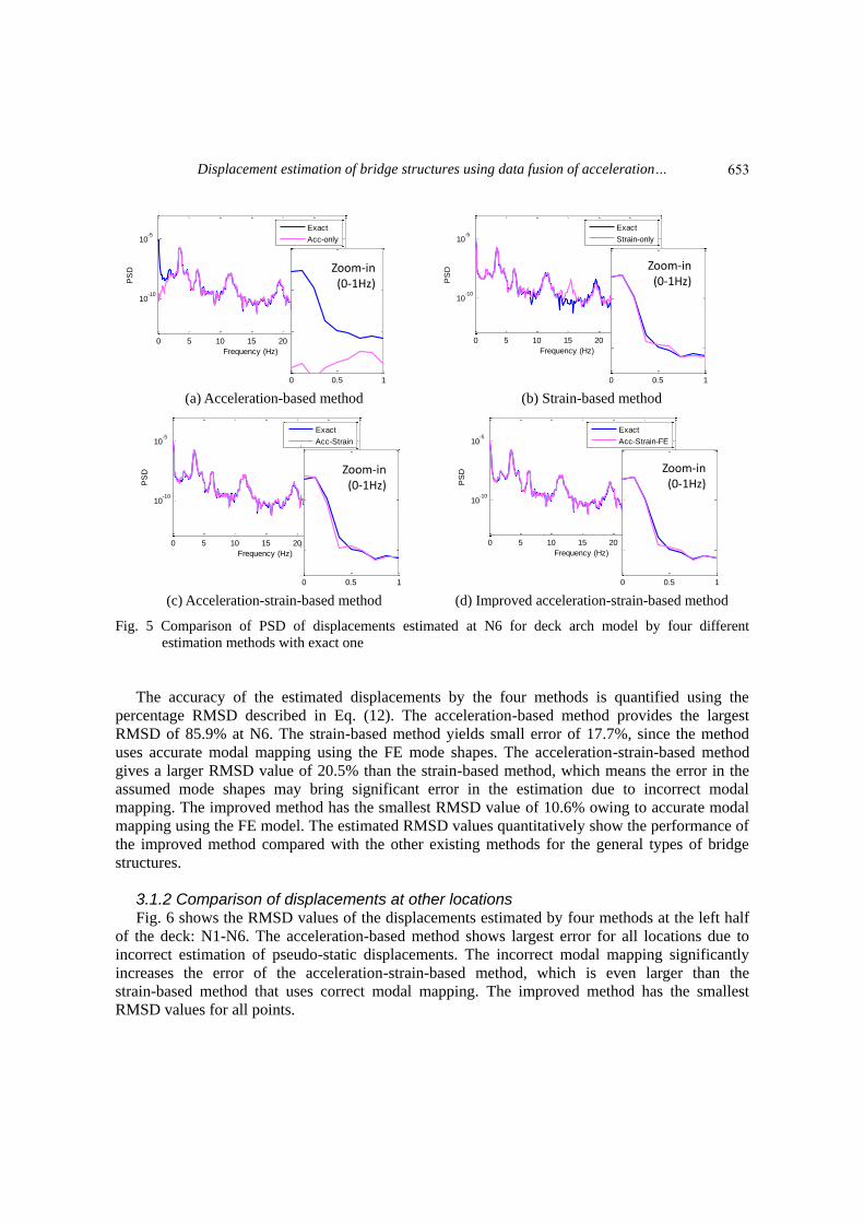
The accuracy of the estimated displacements can be investigated in the different aspects by
looking at the frequency domain. Fig. 5 shows the power spectral density (PSD) of the estimated
displacements compared with that of exact one. Figs. 5(a) and 5(b) show errors of the
acceleration-based and the strain-based methods in low and high frequency range, respectively.
The acceleration-strain-based method shows slightly larger error in estimating the pseudo-static
components near 0 Hz than the improved method (see zoomed-ins of Figs. 5(c) and 5(d)).
The peak at 15.4 Hz shown in the PSD of the strain-based method shows a drawback of the
strain-based method. The bridge model has a mode at 15.4 Hz, and the corresponding mode shape
has a nodal point at N6. This is why there is no peak observed at 15.4 Hz in Fig. 5(a). However,
the strains used in the strain-based method were obtained from non-nodal points, and thus the peak
is clearly observed. In the acceleration-strain-based and improved methods, the high frequency
components contained in the strain were replaced by the components contained in the acceleration,
which resulted in the disappearance of the peak at 15.4 Hz in Figs. 5(c) and 5(d). This illustrates
that the strain-based method is only effective in estimating the very low-frequency components
which have few nodal points.
(a) Acceleration-based method (b) Strain-based method
(c) Acceleration-strain-based method (d) Improved acceleration-strain-based method
Fig. 4 Comparison of displacements estimated at N6 for deck arch bridge model by four different estimation
methods with exact one
0 5 10 15 20-4
-2
0
2
4
6
8
Time (s)
Dis
pla
cem
ent
(mm
)
Exact
Acc-only
0 5 10 15 20-4
-2
0
2
4
6
8
Time (s)
Dis
pla
cem
ent
(mm
)
Exact
Strain-only
0 5 10 15 20-4
-2
0
2
4
6
8
Time (s)
Dis
pla
cem
ent
(mm
)
Exact
Acc-Strain
0 5 10 15 20-4
-2
0
2
4
6
8
Time (s)
Dis
pla
cem
ent
(mm
)
Exact
Acc-Strain-FE
652
Displacement estimation of bridge structures using data fusion of acceleration…
(a) Acceleration-based method (b) Strain-based method
(c) Acceleration-strain-based method (d) Improved acceleration-strain-based method
Fig. 5 Comparison of PSD of displacements estimated at N6 for deck arch model by four different
estimation methods with exact one
The accuracy of the estimated displacements by the four methods is quantified using the
percentage RMSD described in Eq. (12). The acceleration-based method provides the largest
RMSD of 85.9% at N6. The strain-based method yields small error of 17.7%, since the method
uses accurate modal mapping using the FE mode shapes. The acceleration-strain-based method
gives a larger RMSD value of 20.5% than the strain-based method, which means the error in the
assumed mode shapes may bring significant error in the estimation due to incorrect modal
mapping. The improved method has the smallest RMSD value of 10.6% owing to accurate modal
mapping using the FE model. The estimated RMSD values quantitatively show the performance of
the improved method compared with the other existing methods for the general types of bridge
structures.
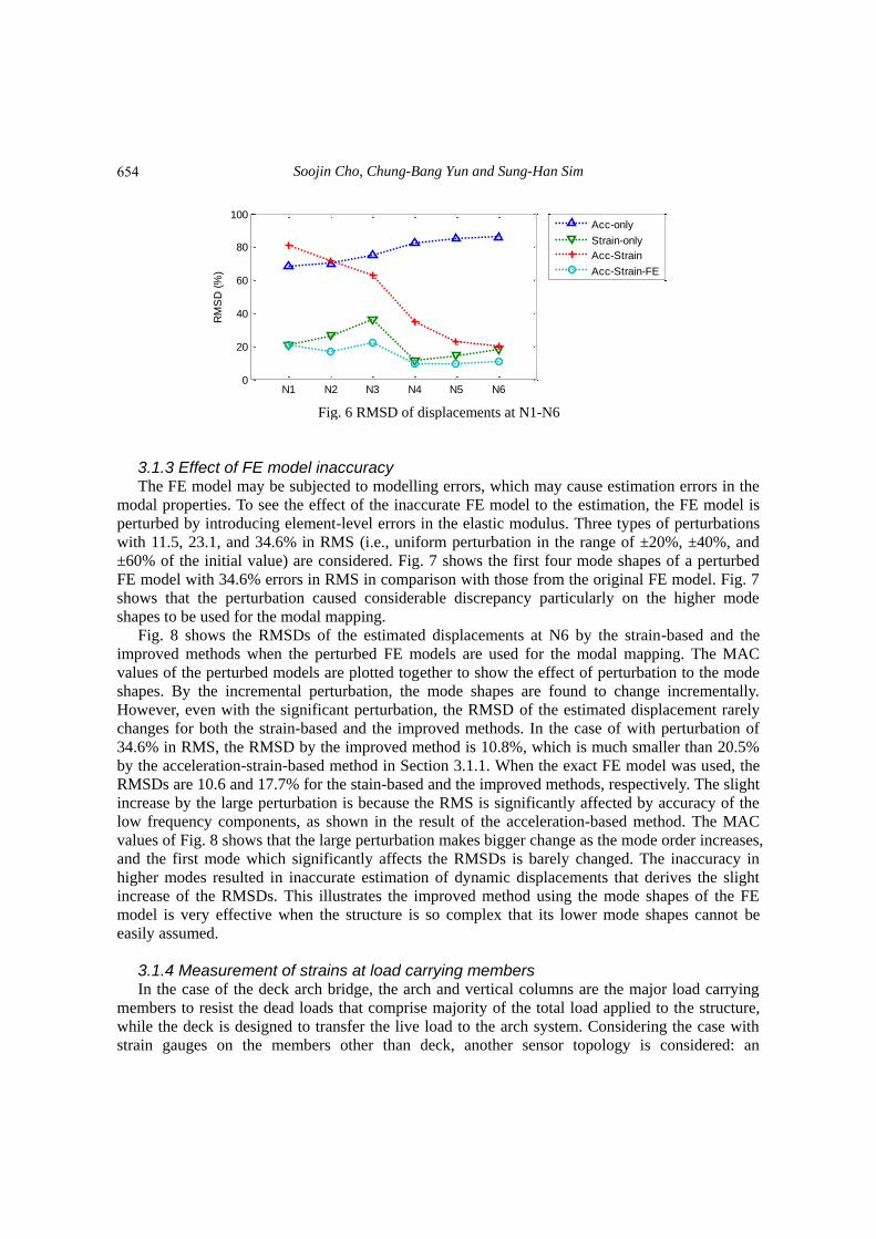
3.1.2 Comparison of displacements at other locations Fig. 6 shows the RMSD values of the displacements estimated by four methods at the left half
of the deck: N1-N6. The acceleration-based method shows largest error for all locations due to
incorrect estimation of pseudo-static displacements. The incorrect modal mapping significantly
increases the error of the acceleration-strain-based method, which is even larger than the
strain-based method that uses correct modal mapping. The improved method has the smallest
RMSD values for all points.
0 5 10 15 20 25 30
10-10
10-5
Frequency (Hz)
PS
D
Exact
Acc-only
0 0.5 110
-10
10-8
10-6
10-4
Zoom-in(0-1Hz)
0 5 10 15 20 25 30
10-10
10-5
Frequency (Hz)
PS
D
Exact
Strain-only
0 0.5 1
10-8
10-6
10-4
Zoom-in(0-1Hz)
0 5 10 15 20 25 30
10-10
10-5
Frequency (Hz)
PS
D
Exact
Acc-Strain
0 0.5 1
10-8
10-6
10-4
Zoom-in(0-1Hz)
0 5 10 15 20 25 30
10-10
10-5
Frequency (Hz)
PS
D
Exact
Acc-Strain-FE
0 0.5 1
10-8
10-6
10-4
Zoom-in(0-1Hz)
653
Soojin Cho, Chung-Bang Yun and Sung-Han Sim
Fig. 6 RMSD of displacements at N1-N6
3.1.3 Effect of FE model inaccuracy The FE model may be subjected to modelling errors, which may cause estimation errors in the
modal properties. To see the effect of the inaccurate FE model to the estimation, the FE model is
perturbed by introducing element-level errors in the elastic modulus. Three types of perturbations
with 11.5, 23.1, and 34.6% in RMS (i.e., uniform perturbation in the range of ±20%, ±40%, and
±60% of the initial value) are considered. Fig. 7 shows the first four mode shapes of a perturbed
FE model with 34.6% errors in RMS in comparison with those from the original FE model. Fig. 7
shows that the perturbation caused considerable discrepancy particularly on the higher mode
shapes to be used for the modal mapping.
Fig. 8 shows the RMSDs of the estimated displacements at N6 by the strain-based and the
improved methods when the perturbed FE models are used for the modal mapping. The MAC
values of the perturbed models are plotted together to show the effect of perturbation to the mode
shapes. By the incremental perturbation, the mode shapes are found to change incrementally.
However, even with the significant perturbation, the RMSD of the estimated displacement rarely
changes for both the strain-based and the improved methods. In the case of with perturbation of
34.6% in RMS, the RMSD by the improved method is 10.8%, which is much smaller than 20.5%
by the acceleration-strain-based method in Section 3.1.1. When the exact FE model was used, the
RMSDs are 10.6 and 17.7% for the stain-based and the improved methods, respectively. The slight
increase by the large perturbation is because the RMS is significantly affected by accuracy of the
low frequency components, as shown in the result of the acceleration-based method. The MAC
values of Fig. 8 shows that the large perturbation makes bigger change as the mode order increases,
and the first mode which significantly affects the RMSDs is barely changed. The inaccuracy in
higher modes resulted in inaccurate estimation of dynamic displacements that derives the slight
increase of the RMSDs. This illustrates the improved method using the mode shapes of the FE
model is very effective when the structure is so complex that its lower mode shapes cannot be
easily assumed.
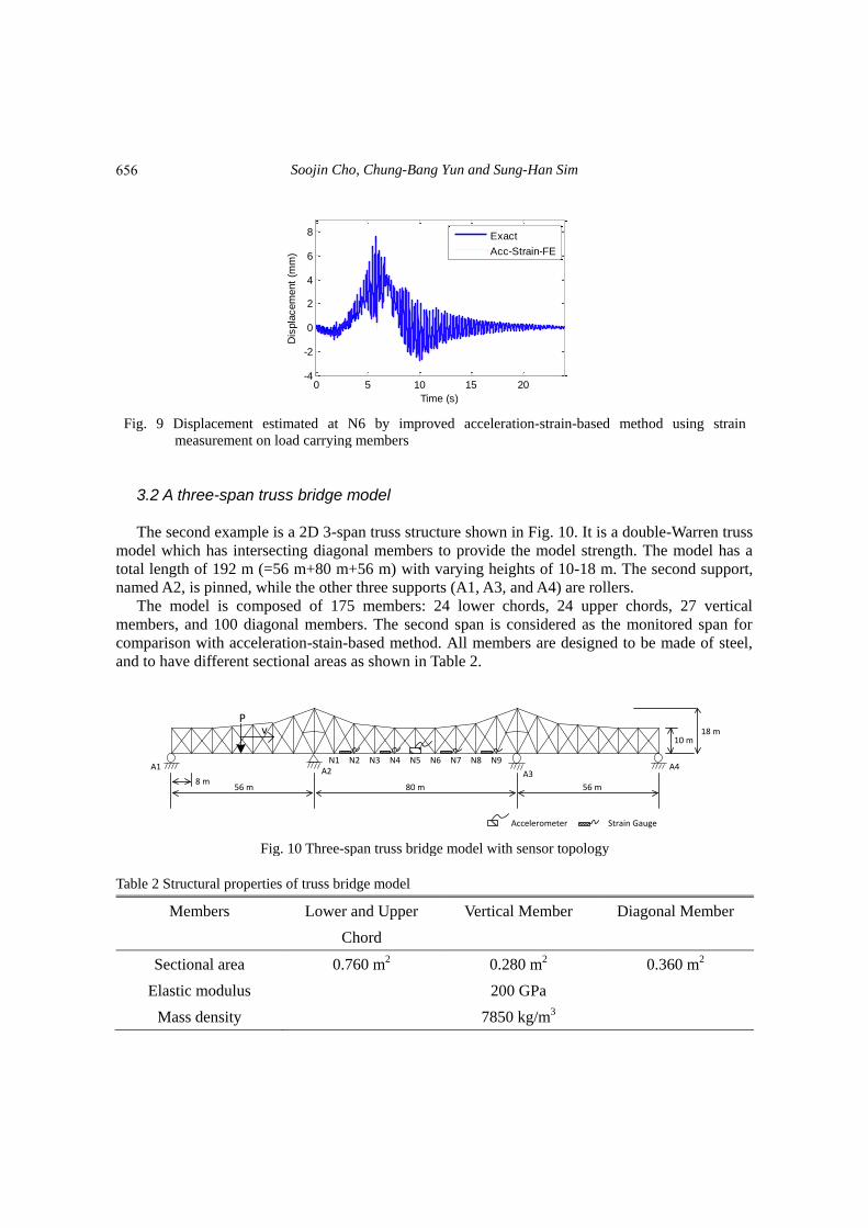
3.1.4 Measurement of strains at load carrying members In the case of the deck arch bridge, the arch and vertical columns are the major load carrying
members to resist the dead loads that comprise majority of the total load applied to the structure,
while the deck is designed to transfer the live load to the arch system. Considering the case with
strain gauges on the members other than deck, another sensor topology is considered: an
N1 N2 N3 N4 N5 N60
20
40
60
80
100R
MS
D (
%)
Acc-only
Strain-only
Acc-Strain
Acc-Strain-FE
654

Displacement estimation of bridge structures using data fusion of acceleration…
accelerometer is at N6, and four strain gauges are at arch members between N12-N13 and
N20-N21, and columns between N3-N14 and N9-N19. Fig. 9 shows the displacement estimated at
N6 using the improved method. The result is very close to the exact one with 9.69% in RMSD,
which is smaller than the value of 10.6% by the strain measurements on the deck described in
Section 3.1.1.
The mode shapes cannot be assumed in an analytical form for the whole structure when the
structure has a complex shape. Therefore, the acceleration-strain-based method using the assumed
sinusoidal mode shapes is applicable only when the strain gauges are on the deck. This example
shows that the proposed improved method based on the FE model has big advantage when the
strain sensors are placed on non-deck members.
Fig. 7 First four mode shapes of perturbed FE model with 34.6% errors in RMS (dotted lines) compared
with those from original model (solid lines)
Fig. 8 RMSD of displacements estimated at N5 for perturbed deck arch FE models
0
5
10
15
20
25
30
RM
SD
(%
)
Exa
ct
11.5%
in R
MS
23.1%
in R
MS
34.6%
in R
MS
Strain-only
Acc-Strain-FE
1
0.95
0.9
0.85
0.8
0.75
0.7
MA
C v
alu
es
1st mode
2nd mode
3rd mode
4th mode
655
Soojin Cho, Chung-Bang Yun and Sung-Han Sim
Fig. 9 Displacement estimated at N6 by improved acceleration-strain-based method using strain
measurement on load carrying members
3.2 A three-span truss bridge model
The second example is a 2D 3-span truss structure shown in Fig. 10. It is a double-Warren truss
model which has intersecting diagonal members to provide the model strength. The model has a
total length of 192 m (=56 m+80 m+56 m) with varying heights of 10-18 m. The second support,
named A2, is pinned, while the other three supports (A1, A3, and A4) are rollers.
The model is composed of 175 members: 24 lower chords, 24 upper chords, 27 vertical
members, and 100 diagonal members. The second span is considered as the monitored span for
comparison with acceleration-stain-based method. All members are designed to be made of steel,
and to have different sectional areas as shown in Table 2.
Fig. 10 Three-span truss bridge model with sensor topology
Table 2 Structural properties of truss bridge model
Members Lower and Upper
Chord
Vertical Member Diagonal Member
Sectional area 0.760 m2 0.280 m2 0.360 m2
Elastic modulus 200 GPa
Mass density 7850 kg/m3
0 5 10 15 20-4
-2
0
2
4
6
8
Time (s)
Dis
pla
cem
ent
(mm
)
Exact
Acc-Strain-FE
8 m56 m 80 m 56 m
10 m18 m
Pv
Accelerometer Strain Gauge
A1 A2 A3A4
N1 N2 N3 N4 N5 N6 N7 N8 N9
656

Displacement estimation of bridge structures using data fusion of acceleration…
(a) Whole FE model (b) Second span only: compared with assumed
mode shapes
Fig. 11 First four mode shapes of FE model
MATLAB Simulink is used to simulate the displacement, acceleration, and strain of the truss
model using a vertical load similar to Fig. 2 moving from left to right on the structure. The
acceleration is assumed to be measured at N5, while the strains of the deck are obtained at the mid
points of four members between N1-N2, N3-N4, N6-N7, and N8-N9. The simulated acceleration
and strains are made contaminated by 5% noise in RMS. Note that acceleration and displacement
are obtained in the vertical direction, while the axial strains are obtained on the lower chord
members.
Given with 4 strain measurements, the first four mode shapes shown in Fig. 11 are used to build
the modal mapping relationship for the strain-based and the improved methods. However, for the
acceleration-strain-based method, sinusoidal mode shapes are approximately obtained only for the
second span of the continuous truss bridge (Cho et al. 2014). Unlike the deck-arch model, the
assumed mode shapes are apparently similar to the shapes from the FE model with small
discrepancy.
Fig. 12 shows the displacements estimated at N5 by four methods in comparison with the exact
ones. The general trends of the results are very similar to those of the deck arch model: the
acceleration-based and the strain-based methods show their weakness in pseudo-static and
dynamic components of displacement, respectively. Though the acceleration-strain-based method
estimates overall shape of the displacement, the amplitude could not be accurately estimated. The
improved acceleration-strain-based method estimates the displacement with the best accuracy
among the four methods in both low- and high- frequency ranges. The RMSD values of the
displacements at N5 are 82.8, 35.1, 34.3, and 22.6% for the four methods, respectively. The error
is slightly larger than the deck arch bridge model, but still the proposed improved method gives the
smallest error.
657

Soojin Cho, Chung-Bang Yun and Sung-Han Sim
(a) Acceleration-based method (b) Strain-based method
(c) Acceleration-strain-based method (d) Improved acceleration-strain-based method
Fig. 12 Comparison of displacements estimated at N5 for three-span truss model by four different estimation
methods with exact one
Fig. 13 RMSD of displacements at N1-N5
The RMSD values estimated at 5 locations (N1-N5) by four methods are compared in Fig. 13.
Due to the mode shapes assumed similar to the shapes from the FE model (see Fig. 11(b)), the
three methods except the acceleration-based method show increasing values as the sensor location
gets close to the left support due to smaller amplitude of displacement, while the
acceleration-based method shows nearly-constant level of large error due to incorrect estimation of
pseudo-static displacements. Similar to the deck arch bridge model, the improved method shows
the smallest RMSD values for all locations.
0 5 10 15 20-5
0
5
10
Time (s)
Dis
pla
cem
ent
(mm
)
Exact
Acc-only
0 5 10 15 20-5
0
5
10
Time (s)
Dis
pla
cem
ent
(mm
)
Exact
Strain-only
0 5 10 15 20-5
0
5
10
Time (s)
Dis
pla
cem
ent
(mm
)
Exact
Acc-Strain
0 5 10 15 20-5
0
5
10
Time (s)
Dis
pla
cem
ent
(mm
)
Exact
Acc-Strain-FE
N1 N2 N3 N4 N50
20
40
60
80
100
RM
SD
(%
)
Acc-only
Strain-only
Acc-Strain
Acc-Strain-FE
658

Displacement estimation of bridge structures using data fusion of acceleration…
4. Experimental validation 4.1 Test bridge and test setup
To validate the performance of the improved method for a real bridge structure, a field testing
was conducted on a prestressed concrete bridge shown in Fig. 14, which was developed as a
test-bed of bridge measurement technology by KICT (Korea Institute of Construction Technology).
The bridge is a single span prestressed concrete girder bridge with four girders and its span length
is 11m.
To estimate the displacement by the improved method, acceleration and strain were measured
on the bridge: three strain gages were installed beneath the bridge girder at L1, L3, and L4, and
two accelerometers were placed at L2 and L3, as shown in Fig. 14. In addition, two laser
displacement sensors were also collocated at L2 and L3 to provide reference displacements. To
excite the bridge, a 28.63 ton truck ran on the bridge with the speed of 15 km/h.
4.2 Finite element model of test bridge
To build the modal mapping matrix for the strain-based and the improved methods, an FE
model of the bridge was built using ANSYS as shown in Fig. 15. The first three mode shapes for
the displacement and strain were extracted from the FE model to build the modal mapping of
strain to displacement. Torsional modes have effectively similar shapes to the bending modes for
individual girders (Cho et al. 2014). Thus, the information of the torsional modes is excluded in
the modal mapping procedure.
Fig. 14 Test bridge and sensor locations
Fig. 15 FE model of test bridge
Accelerometer
Strain gage
Laser Displacement Sensors
11 m
L1 L2 L3 L4
8.55 m5.63 m
4.12 m1.53m
659

Soojin Cho, Chung-Bang Yun and Sung-Han Sim
4.3 Displacement estimation The displacements at L2 and L3 were estimated by the improved method, and the results were
compared with the reference values measured with laser displacement meters. The neutral axis of
the bridge was initially assumed to be 0.25 m from the sensor level (bottom of girders) for the
strain-based, the acceleration-strain-based, and the improved methods. The neutral axis is
compensated in the acceleration-strain-based and the improved methods, but not in the
strain-based method. Fig. 16 compares the estimated displacements by four methods with the
reference values at L3 when the truck ran. As in the numerical simulations, the acceleration-based
method shows weakness in estimating pseudo-static components. The strain-based method cannot
estimate accurate pseudo-static component due to the inaccurate neutral axis in the FE model. The
acceleration-strain-based and the improved methods estimated displacements very similar to the
reference ones as shown in Figs. 16(c) and 16(d).
The RMSD values of the displacements estimated by four methods at L2 and L3 are tabulated
in Table 3. While the acceleration-based and the strain-based methods have large errors over 25%
in RMSD, the acceleration-strain-based and the improved methods have smaller error. However,
the acceleration-strain-based and the improved methods have the smallest measures (less than 6%),
since the assumed sinusoidal mode shapes are very good for this beam-type of bridge.
The peak displacement is another important measure for health monitoring of civil
infrastructure. Similar to the RMSD, the percentage peak error can be defined as
max maxPeak Error (%) 100
max
est ref
ref
u u
u
(10)
The peak errors are calculated and shown in Table 3, which shows that the improved method
estimates the peak displacements more accurately than the acceleration-strain-based method: 2.80
and 3.75% versus 3.61 and 6.59% at L2 and L3, respectively. These results indicate that the
proposed improved method has better accuracy than the acceleration-strain-based method even for
this simply supported bridge. Especially, considering the peak displacement by the moving truck is
about 4 mm, the improved method is found to be appropriate for the displacement measurement of
civil engineering structures that generally have low displacement levels.
Table 3 RMSD (%) and peak error (%) between estimated and reference displacements
Methods L2 L3
RMSD (%) Peak Error
(%)
RMSD (%) Peak Error
(%)
Acceleration-based method 99.0 -81.4 99.0 -80.3
Strain-based method 28.7 -27.4 33.8 -32.0
Acceleration-strain-based method 5.62 3.61 5.75 6.59
Improved acceleration-strain-based
method
5.88 2.80 5.70 3.75
660

Displacement estimation of bridge structures using data fusion of acceleration…
(a) Acceleration-based method (b) Strain-based method
(c) Acceleration-strain-based method (d) Improved acceleration-strain-based method
Fig. 16 Comparison of displacements estimated by improved method with reference: at L3
5. Conclusions
In this paper, an improved displacement estimation method based on data fusion of acceleration
and strain has been proposed for the application to general types of bridge structures whose mode
shapes may not be assumed in analytical (e.g., sinusoidal) function. The improvement has been
made by employing the mode shapes from an FE model in the modal mapping of strain to
displacement. The performance of the improved method has been verified by numerical
simulations on a deck arch structure and a three-span truss structure with complex shapes. Field
experiment on a prestressed concrete bridge has also been carried out. The estimated
displacements by four methods, acceleration-based method, strain-based method,
acceleration-strain-based method, and improved method, have been compared.
The result of this study can be summarized as:
(1) In the numerical simulations on the deck arch model and the truss model, the proposed
method estimated displacements with better accuracy than the other methods at all
locations of the structure owing to the accurate modal mapping using the FE model.
(2) The perturbation of the FE model has increased the inaccuracy of the improved method.
However, at the center locations, large perturbation (34.6% in RMS) resulted in the RMSD
errors of 10.8%, which is less than 20.5% by the acceleration-strain-based method, which
shows the effectiveness of the proposed method with somewhat inaccurate FE model.
(3) The proposed method estimated the displacement equivalently well using the strain data on
non-beam type members such as truss and arch, which shows its good compatibility of the
improved method to more general types of structures.
0 2 4 6 8-1
0
1
2
3
4
5
Time (s)
Dis
pla
cem
ent
(mm
)
Exact
Acc-only
0 2 4 6 8-1
0
1
2
3
4
5
Time (s)
Dis
pla
cem
ent
(mm
)
Exact
Strain-only
0 2 4 6 8-1
0
1
2
3
4
5
Time (s)
Dis
pla
cem
ent
(mm
)
Exact
Acc-Strain
0 2 4 6 8-1
0
1
2
3
4
5
Time (s)
Dis
pla
cem
ent
(mm
)
Exact
Acc-Strain-FE
661

Soojin Cho, Chung-Bang Yun and Sung-Han Sim
(4) In the field test on a prestressed concrete bridge, the proposed method accurately estimated
the dynamic displacements, whose maximum amplitudes are less than 4mm. The RMSD by
the improved method was similar to those by the acceleration-strain-based method, while
the peak displacement was estimated more accurately with less than 4% errors.
Acknowledgements
This research was supported by Basic Science Research Program through the National
Research Foundation of Korea (NRF) funded by the Ministry of Science, ICT & Future Planning
(NRF-2012-R1A1A1-042867). The support is gratefully appreciated.
Reference
Altunisik, A.C., Bayraktar, A. and Ozdemir, H. (2012) “Seismic safety assessment of eynel highway steel
bridge using ambient vibration measurements”, Smart Struct. Syst., 10(2), 131-154.
Atkinson, K.E. (2008), An introduction to numerical analysis, John Wiley & Sons.
Bani-Hani, K.A., Zibdeh, H.S. and Hamdaoui, K. (2008) “Health monitoring of a historical monument in
Jordan based on ambient vibration test”, Smart Struct. Syst., 4(2), 195-208.
Ç elibi, M. (2000), “GPS in dynamic monitoring of long-period structures”, Soil Dyn. Earthq. Eng., 20,
477-483.
Cho, S., Sim, S.H., Park, J.W. and Lee, J. (2014), “Extension of indirect displacement estimation method
using acceleration and strain to various types of beam structures”, Smart Struct. Syst.,14(4), 699-718.
Chung, W., Kim, S., Kim, N. and Lee, H. (2008), “Deflection estimation of a full scale PSC girder using
long-gauge fiber optic sensors”, Constr. Build. Mater., 22(3), 394-401.
Doebling, S.W., Farrar, C.R. and Prime, M.B. (1998), “A summary review of vibration-based damage
identification methods”, Shock Vib. Digest, 30, 91-105.
Faulkner, B.C., Barton, F., Baber, T.T. and McKeel, W.T. (1996), Determination of bridge using acceleration
data, Virgina Transportation Research Council. VA, USA.
Foss, G. and Haugse, E. (1995), “Using modal test results to develop strain to displacement transformations”,
Proceedings of the 13th Int. Modal Analysis Conf.
Gindy, M., Nassif, H.H. and Velde, J. (2008), “Bridge displacement estimates from measured acceleration
records”, Transport. Res. Rec., 2028, 136-145.
Jo, H., Sim, S.H., Tatkowski, A., Spencer, Jr., B.F. and Nelson, M.E. (2013), “Feasibility of displacement
monitoring using low-cost GPS re-ceivers”, Struct. Control Health., 20(9), 1240-1254.
Kandula, V., DeBrunner, L., DeBrunner, V. and Rambo-Roddenberry, M. (2012), “Field testing of indirect
displacement estimation using accelerometers”, Proceedings of the Conf. Record of the 46th Asilomar
Conf. Signals, Systems, and Computers.
Kang, L.H., Kim, D.K. and Han, J.H. (2007), “Estimation of dynamic structural displacements using fiber
Bragg grating strain sensors”, J. Sound Vib., 305(3), 534-542.
Lee, H.S., Hong, Y.H. and Park, H.W. (2010), “Design of an FIR filter for the displacement reconstruction
using measured acceleration in low-frequency dominant structures”, Int. J. Numer. Meth. Eng., 82(4),
403-434.
Lee, J.J., Fukuda, Y., Shinozuka, M., Cho, S. and Yun, C. (2007), “Development and application of a
vision-based displacement measurement system for structural health monitoring of civil structures”, Smart
Struct. Syst., 3(3), 373-384.
Majumder, M., Gangopadhyay, T.K., Chakraborty, A.K., Dasgupta, K. and Bhattacharya, D.K. (2008),
“Fibre Bragg gratings in structural health monitoring—Present status and applications”, Sensor. Actuat.
662
Displacement estimation of bridge structures using data fusion of acceleration…
A-Phys., 147(1), 150-164.
Nassif, H.H., Gindy, M. and Davis, J. (2005), “Comparison of laser Doppler vibrometer with contact sensors
for monitoring bridge deflection and vibration”, NDT & E Inter., 38, 213-218.
Omenzetter, P., Brownjohn, J.M.W. and Moyo, P. (2004), “Identification of unusual events in multi-channel
bridge monitoring data”, Mech. Syst. Signal Pr., 18(2), 409-430.
Park, J.W., Sim, S.H. and Jung, H.J. (2013), “Displacement estimation using multimetric data fusion”,
IEEE/ASME Trans. Mechatronics, 18(6), DOI: 10.1109/TMECH.2013.2275187.
Park, K.T., Kim, S.H., Park, H.S. and Lee, K.W. (2005), “The determination of bridge displacement using
measured acceleration”, Eng. Struct., 27(3), 371-378.
Shin, S., Lee, S.U. and Kim, N.S. (2012), “Estimation of bridge displacement responses using FBG sensors
and theoretical mode shapes”, Struct. Eng. Mech., 42(2), 229-245.
Sigurdardottir, D.H. and Glisic, B. (2014), “Detecting minute damage in beam-like structures using the
neutral axis location”, Smart Mater. Struct., 23(12), 125042.
Xu, L., Guo, J.J. and Jiang, J.J. (2002), “Time-frequency analysis of a suspension bridge based on GPS”, J.
Sound Vib., 254(1), 105-116.
663